

Page 1

AIR CONDITIONERS CITY MULTI
Models PQRY-P200YMF-B, P250YMF-B
CMB-P104, P105, P106, P108, P1010, P1013, P1016V-E
Service Handbook
Page 2

Contents
1 PRECAUTIONS FOR DEVICES THAT USE R407C REFRIGERANT ..... 1
[1] Storage of Piping Material ................................................................. 2
[2] Piping Machining ............................................................................... 3
[3] Necessary Apparatus and Materials and Notes on Their Handling .. 4
[4] Brazing .............................................................................................. 5
[5] Airtightness Test ................................................................................ 6
[6] Vacuuming ........................................................................................ 6
[7] Charging of Refrigerant ..................................................................... 7
[8] Dryer ................................................................................................. 7
2 COMPONENT OF EQUIPMENT ............................................................. 8
[1] Appearance of Components ............................................................. 8
[2] Refrigerant Circuit Diagram and Thermal Sensor ........................... 15
[3] Equipment Composition .................................................................. 17
[4] Electrical Wiring Diagram ................................................................ 18
[5] Standard Operation Data ................................................................ 27
[6] Function of Dip SW and Rotary SW................................................ 29
[7] External Input/Output Specifications ............................................... 32
3 TEST RUN ............................................................................................. 33
[1] Before Test Run ............................................................................... 33
[2] Address setting ............................................................................... 38
[3] Test Run Method ............................................................................. 43
4 GROUPING REGISTRATION OF INDOOR UNITS WITH REMOTE
CONTROLLER ....................................................................................... 44
5 CONTROL .............................................................................................. 50
[1] Control of Heat Source Unit ............................................................ 50
[2] Control box cooling system ............................................................. 54
[3] Control of BC Controller .................................................................. 55
[4] Operation Flow Chart ...................................................................... 56
[5] List of Major Component Functions ................................................ 62
[6] Resistance of Temperature Sensor ................................................. 65
6 REFRIGERANT AMOUNT ADJUSTMENT ............................................ 66
[1] Refrigerant Amount and Operating Characteristics ........................ 66
[2] Adjustment and Judgement of Refrigerant Amount ........................ 66
7 TROUBLESHOOTING ........................................................................... 75
[1] Principal Parts ................................................................................. 75
[2] BC Controller Disassembly Procedure.......................................... 103
[3] Self-diagnosis and Countermeasures Depending on the
Check Code Displayed .................................................................. 109
[4] LED Monitor Display ..................................................................... 131
8 PREPARATION, REPAIRS AND REFRIGERANT REFILLING
WHEN REPAIRING LEAKS ................................................................. 141
[1] Location of leaks: Extension piping or indoor units (when cooling) ... 141
[2] Location of leaks: Heat Source Unit (Cooling mode) .................... 141
[3] Location of Leaks: Extension Piping or Indoor Units
(Heating mode) ............................................................................. 142
[4] Location of Leaks: Heat Source Unit (when Heating) ................... 142
9 CHECK THE COMPOSITION OF THE REFRIGERANT ..................... 143
0 DIFFERENCES BETWEEN THE PREVIOUS REFRIGERANT
AND THE NEW REFRIGERANT ......................................................... 145
[1] Chemical Characteristics .............................................................. 145
[2] Chances in Composition ............................................................... 145
[3] Pressure Characteristics ............................................................... 146
A REFRIGERATOR OIL .......................................................................... 147
[1] Refrigerator Oil with HFC Based Refrigerants .............................. 147
[2] Influence of Contaminants ............................................................ 147
Page 3
Safety precautions
Before installation and electric work
▲
Before installing the unit, make sure you read all
the “Safety precautions”.
▲
The “Safety precautions” provide very important
points regarding safety. Make sure you follow
them.
▲
This equipment may not be applicable to
EN61000-3-2: 1995 and EN61000-3-3: 1995.
▲
This equipment may have an adverse effect on
equipment on the same electrical supply system.
Please report to or take consent by the supply
▲
authority before connection to the system.
Symbols used in the text
Warning:
Describes precautions that should be observed to
prevent danger of injury or death to the user.
Caution:
Describes precautions that should be observed to
prevent damage to the unit.
Symbols used in the illustrations
: Indicates an action that must be avoided.
: Indicates that important instructions must be followed.
: Indicates a part which must be grounded.
: Indicates that caution should be taken with rotating parts.
(This symbol is displayed on the main unit label.)
<Color: Yellow>
: Indicates that the main switch must be turned off before
servicing. (This symbol is displayed on the main unit label.)
<Color: Blue>
: Beware of electric shock (This symbol is displayed on the
main unit label.) <Color: Yellow>
: Beware of hot surface (This symbol is displayed on the main
unit label.) <Color: Yellow>
: Please pay attention to electric shock fully because
ELV
this is not Safety Extra Low-Voltage (SELV) circuit.
And at servicing, please shut down the power supply
for both of Indoor Unit and Heat Source Unit.
Warning:
Carefully read the labels affixed to the main unit.
Warning:
• Ask the dealer or an authorized technician to install the air
conditioner.
- Improper installation by the user may result in water leakage,
electric shock, or fire.
• Install the air unit at a place that can withstand its weight.
- Inadequate strength may cause the unit to fall down, resulting
in injuries.
• Use the specified cables for wiring. Make the connections
securely so that the outside force of the cable is not
applied to the terminals.
- Inadequate connection and fastening may generate heat and
cause a fire.
• Prepare for typhoons and other strong winds and earthquakes and install the unit at the specified place.
- Improper installation may cause the unit to topple and result
in injury.
• Always use an air cleaner, humidifier, electric heater, and
other accessories specified by Mitsubishi Electric.
- Ask an authorized technician to install the accessories.
Improper installation by the user may result in water leakage,
electric shock, or fire.
• Never repair the unit. If the air conditioner must be
repaired, consult the dealer.
- If the unit is repaired improperly, water leakage, electric
shock, or fire may result.
• Do not touch the heat exchanger fins.
- Improper handling may result in injury.
• If refrigerant gas leaks during installation work, ventilate
the room.
- If the refrigerant gas comes into contact with a flame,
poisonous gases will be released.
• Install the air conditioner according to this Installation
Manual.
- If the unit is installed improperly, water leakage, electric
shock, or fire may result.
• Have all electric work done by a licensed electrician
according to “Electric Facility Engineering Standard” and
“Interior Wire Regulations”and the instructions given in
this manual and always use a special circuit.
- If the power source capacity is inadequate or electric work is
performed improperly, electric shock and fire may result.
• Securely install the cover of control box and the panel.
- If the cover and panel are not installed properly, dust or water
may enter the heat source unit and fire or electric shock may
result.
• When installing and moving the air conditioner to another
site, do not charge the it with a refrigerant different from
the refrigerant (R407C) specified on the unit.
- If a different refrigerant or air is mixed with the original
refrigerant, the refrigerant cycle may malfunction and the unit
may be damaged.
• If the air conditioner is installed in a small room, measures
must be taken to prevent the refrigerant concentration
from exceeding the safety limit even if the refrigerant
should leak.
- Consult the dealer regarding the appropriate measures to
prevent the safety limit from being exceeded. Should the
refrigerant leak and cause the safety limit to be exceeded,
hazards due to lack of oxygen in the room could result.
• When moving and reinstalling the air conditioner, consult
the dealer or an authorized technician.
- If the air conditioner is installed improperly, water leakage,
electric shock, or fire may result.
• After completing installation work, make sure that refrigerant gas is not leaking.
- If the refrigerant gas leaks and is exposed to a fan heater,
stove, oven, or other heat source, it may generate noxious
gases.
• Do not reconstruct or change the settings of the protection devices.
- If the pressure switch, thermal switch, or other protection
device is shorted and operated forcibly, or parts other than
those specified by Mitsubishi Electric are used, fire or
explosion may result.
• To dispose of this product, consult your dealer.
• The installer and system specialist shall secure safety
against leakage according to local regulation or standards.
- Following standards may be applicable if local regulation are
not available.
• Pay a special attention to the place, such as a basement,
etc. where refrigeration gas can stay, since refrigerant is
heavier than the air.
Page 4
11
1 PRECAUTIONS FOR DEVICES THAT USE R407C REFRIGERANT
11
Caution
Do not use the existing refrigerant piping.
• The old refrigerant and refrigerator oil in the existing
piping contains a large amount of chlorine which may
cause the refrigerator oil of the new unit to deteriorate.
Use refrigerant piping made of **C1220T phosphorus deoxidized copper as specified in the *JIS H3300
“Copper and copper alloy seamless pipes and tubes”.
In addition, be sure that the inner and outer surfaces
of the pipes are clean and free of hazardous sulphur,
oxides, dust/dirt, shaving particles, oils, moisture, or
any other contaminant.
• Contaminants on the inside of the refrigerant piping
may cause the refrigerant residual oil to deteriorate.
*JIS: Japanese Industrial Standard
**: Comparable to CU-DHP (CUPROCLIMA), Cu-bl
(AFNOR), C12200 (ASTN), SF-Cu (DIN)
Store the piping to be used during installation indoors
and keep both ends of the piping sealed until just
before brazing. (Store elbows and other joints in a
plastic bag.)
• If dust, dirt, or water enters the refrigerant cycle,
deterioration of the oil and compressor trouble may
result.
Use a vacuum pump with a reverse flow check valve.
• The vacuum pump oil may flow back into the refrigerant cycle and cause the refrigerator oil to deteriorate.
Do not use the following tools that have been used
with conventional refrigerants.
(Gauge manifold, charge hose, gas leak detector, reverse flow check valve, refrigerant charge base,
vacuum gauge, refrigerant recovery equipment.)
• If the conventional refrigerant and refrigerator oil are
mixed in the R407C, the refrigerant may deteriorated.
• If water is mixed in the R407C, the refrigerator oil
may deteriorate.
• Since R407C does not contain any chlorine, gas
leak detectors for conventional refrigerants will not
react to it.
Do not use a charging cylinder.
• Using a charging cylinder may cause the refrigerant
to deteriorate.
Be especially careful when managing the tools.
• If dust, dirt, or water gets in the refrigerant cycle, the
refrigerant may deteriorate.
Use ester oil, ether oil or alkylbenzene (small
amount) as the refrigerator oil to coat flares and
flange connections.
• The refrigerator oil will degrade if it is mixed with a
large amount of mineral oil.
Use liquid refrigerant to seal the system.
• If gas refrigerant is used to seal the system, the composition of the refrigerant in the cylinder will change
and performance may drop.
Do not use a refrigerant other than R407C.
• If another refrigerant (R22, etc.) is used, the chlorine
in the refrigerant may cause the refrigerator oil to deteriorate.
If the refrigerant leaks, recover the refrigerant in the
refrigerant cycle, then recharge the cycle with the
specified amount of the liquid refrigerant indicated
on the air conditioner.
• Since R407C is a nonazeotropic refrigerant, if additionally charged when the refrigerant leaked, the composition of the refrigerant in the refrigerant cycle will
change and result in a drop in performance or abnormal stopping.
–1–
Page 5
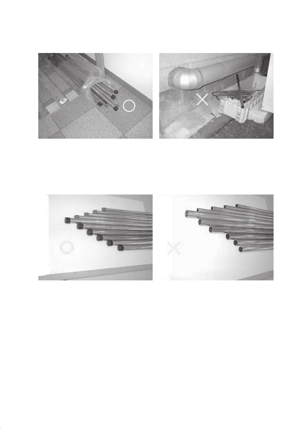
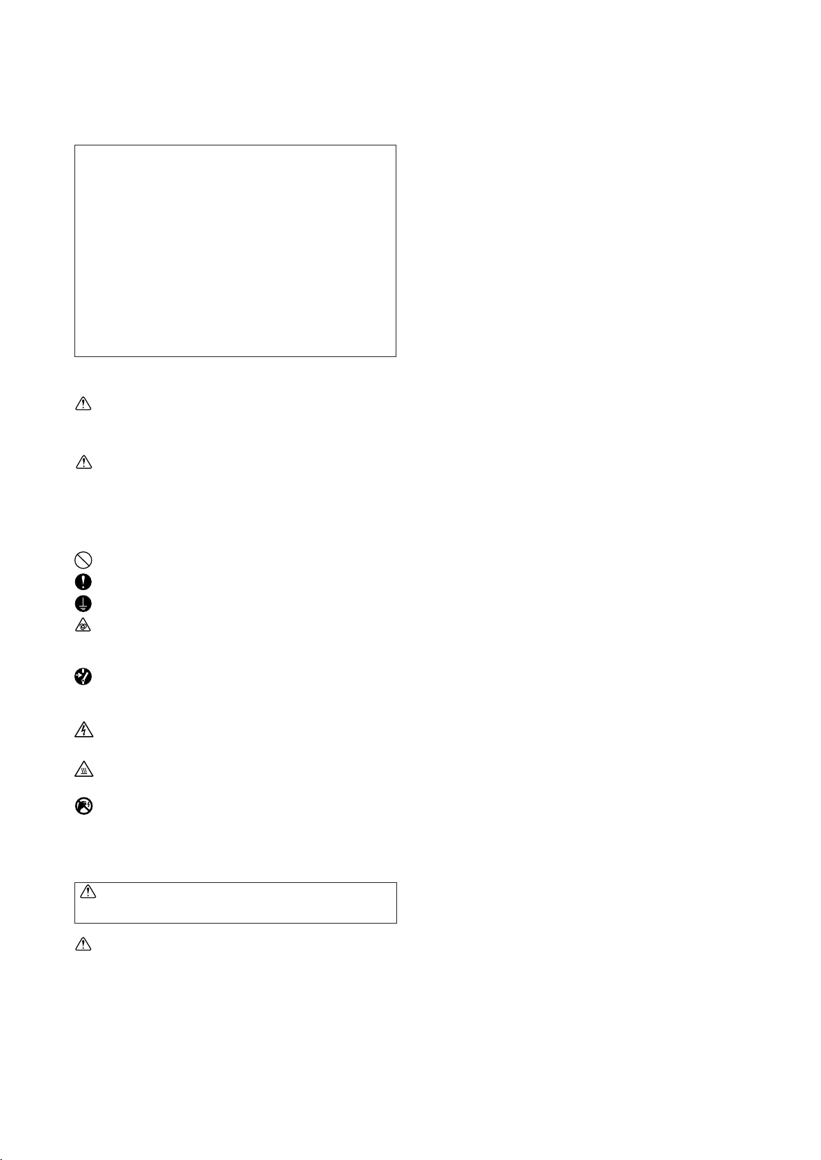
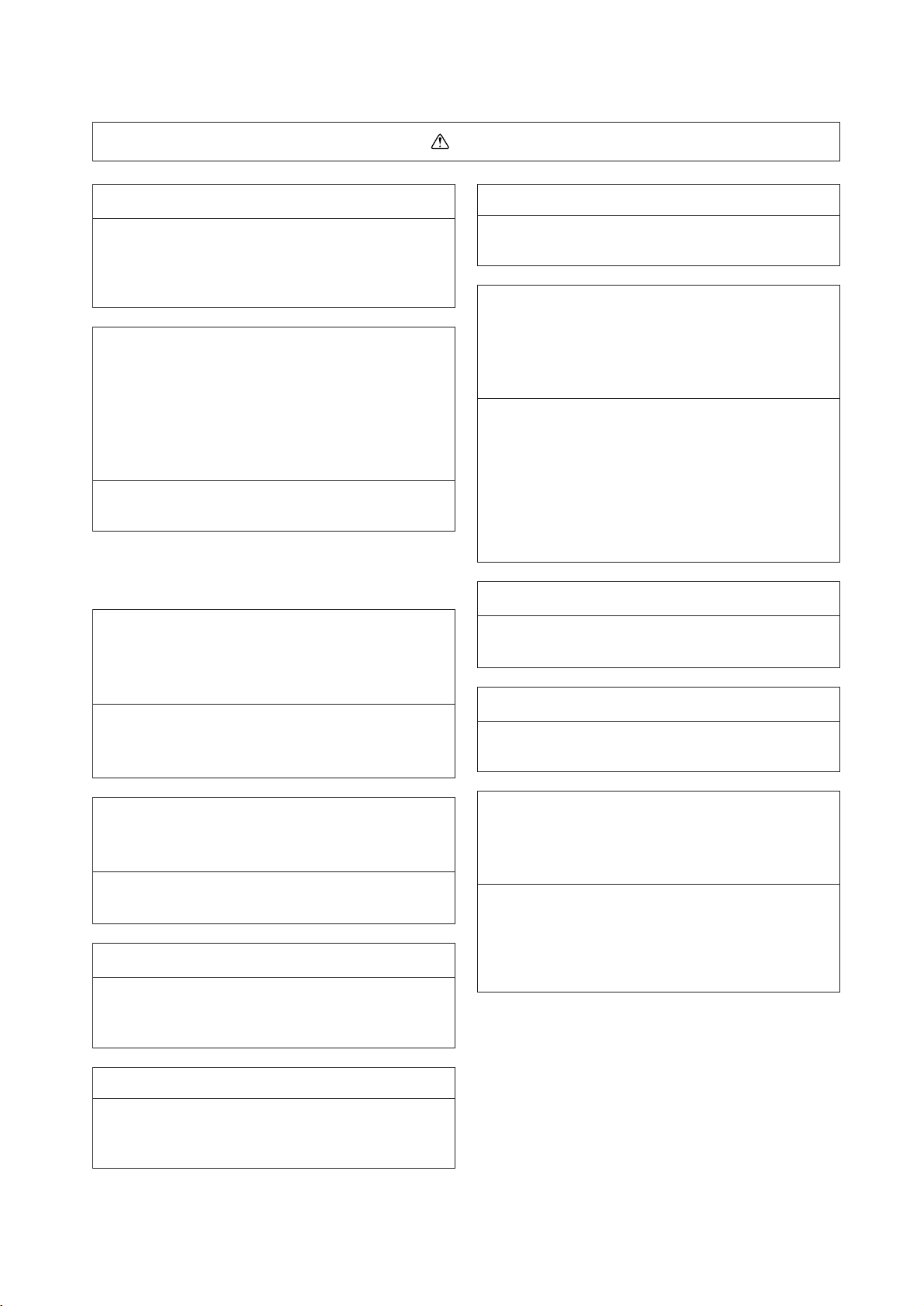
[1] Storage of Piping Material
(1) Storage location
Store the pipes to be used indoors. (Warehouse at site or owner’s warehouse)
Storing them outdoors may cause dirt, waste, or water to infiltrate.
(2) Pipe sealing before storage
Both ends of the pipes should be sealed until immediately before brazing.
Wrap elbows and T’s in plastic bags for storage.
* The new refrigerator oil is 10 times more hygroscopic than the conventional refrigerator oil (such as Suniso). Water
infiltration in the refrigerant circuit may deteriorate the oil or cause a compressor failure. Piping materials must be
stored with more care than with the conventional refrigerant pipes.
–2–
Page 6
[2] Piping Machining
Use ester oil, ether oil or alkylbenzene (small amount) as the refrigerator oil to coat flares and flange connections.
Use only the necessary minimum quantity of oil !
Reason :
1. The refrigerator oil used for the equipment is highly hygroscopic and may introduce water inside.
Notes :
• Introducing a great quantity of mineral oil into the refrigerant circuit may also cause a compressor failure.
• Do not use oils other than ester oil, ether oil or alkylbenzene.
–3–
Page 7
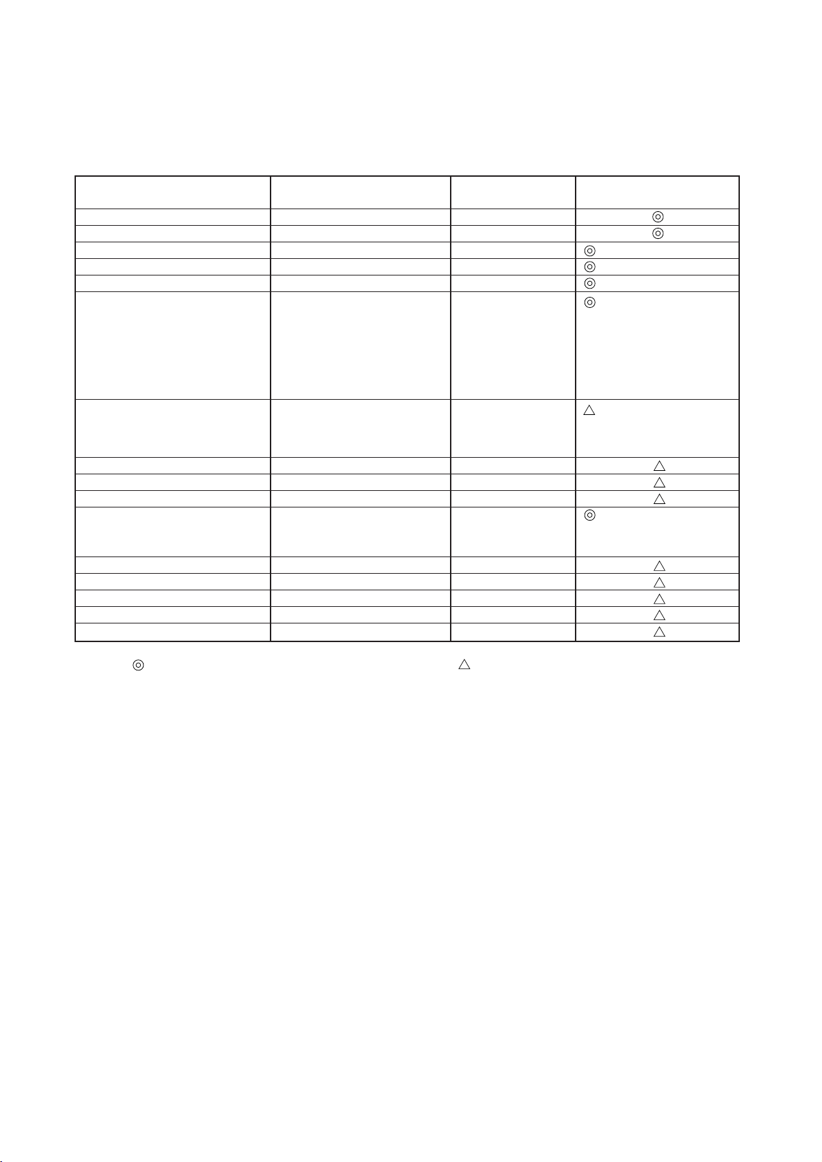
[3] Necessary Apparatus and Materials and Notes on Their Handling
The following tools should be marked as dedicated tools for R407C.
<<Comparison of apparatus and materials used for R407C and for R22>>
Apparatus Used Use R22 R407C
Gauge manifold Evacuating, refrigerant filling Current product
Charging hose Operation check Current product
Charging cylinder Refrigerant charging Current product Do not use.
Gas leakage detector Gas leakage check Current product Shared with R134a
Refrigerant collector Refrigerant collection R22 For R407C use only
Refrigerant cylinder Refrigerant filling R22
Vacuum pump Vacuum drying Current product
Vacuum pump with a check valve Current product
Flare tool Flaring of pipes Current product
Bender Bending of pipes Current product
Application oil Applied to flared parts Current product
Torque wrench Tightening of flare nuts Current product
Pipe cutter Cutting of pipes Current product
Welder and nitrogen cylinder Welding of pipes Current product
Refrigerant charging meter Refrigerant charging Current product
Vacuum gauge Checking the vacuum degree Current product
Identification of dedicated use for R407C
: Record refrigerant
name and put brown
belt on upper part of
cylinder.
Can be used by
attaching an adapter
with a check valve.
Ester oil or Ether oil or
Alkybenzene (Small
amount)
Symbols :
Tools for R407C must be handled with more care than those for conventional refrigerants. They must not come into contact
with any water or dirt.
To be used for R407C only. Can also be used for conventional refrigerants.
–4–
Page 8
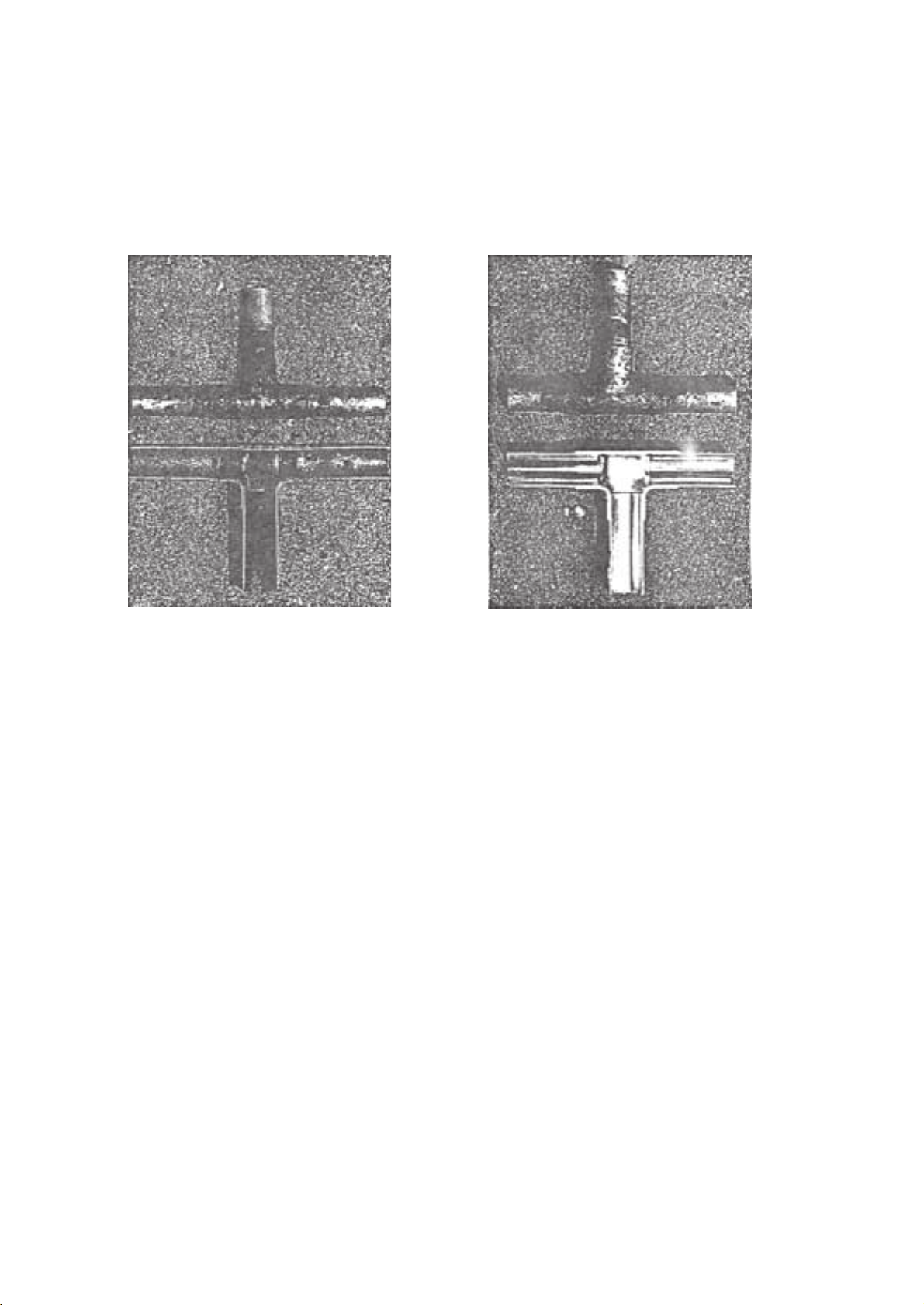
[4] Brazing
No changes from the conventional method, but special care is required so that foreign matter (ie. oxide scale, water, dirt,
etc.) does not enter the refrigerant circuit.
Example : Inner state of brazed section
When non-oxide brazing was not used When non-oxide brazing was used
Items to be strictly observed :
1. Do not conduct refrigerant piping work outdoors on a rainy day.
2. Apply non-oxide brazing.
3. Use a brazing material (Bcup-3) which requires no flux when brazing between copper pipes or between a copper pipe
and copper coupling.
4. If installed refrigerant pipes are not immediately connected to the equipment, then braze and seal both ends of them.
Reasons :
1. The new refrigerant oil is 10 times more hygroscopic than the conventional oil. The probability of a machine failure if
water infiltrates is higher than with conventional refrigerant oil.
2. A flux generally contains chlorine. A residual flux in the refrigerant circuit may generate sludge.
Note :
• Commercially available antioxidants may have adverse effects on the equipment due to its residue, etc. When
applying non-oxide brazing, use nitrogen.
–5–
Page 9
[5] Airtightness Test
No changes from the conventional method. Note that a refrigerant leakage detector for R22 cannot detect R407C
leakage.
Halide torch R22 leakage detector
Items to be strictly observed :
1. Pressurize the equipment with nitrogen up to the design pressure and then judge the equipment’s airtightness, taking
temperature variations into account.
2. When investigating leakage locations using a refrigerant, be sure to use R407C.
3. Ensure that R407C is in a liquid state when charging.
Reasons :
1. Use of oxygen as the pressurized gas may cause an explosion.
2. Charging with R407C gas will lead the composition of the remaining refrigerant in the cylinder to change and this
refrigerant can then not be used.
Note :
• A leakage detector for R407C is sold commercially and it should be purchased.
[6] Vacuuming
1. Vacuum pump with check valve
A vacuum pump with a check valve is required to prevent the vacuum pump oil from flowing back into the refrigerant
circuit when the vacuum pump power is turned off (power failure).
It is also possible to attach a check valve to the actual vacuum pump afterwards.
2. Standard degree of vacuum for the vacuum pump
Use a pump which reaches 0.5 Torr (500 MICRON) or below after 5 minutes of operation.
In addition, be sure to use a vacuum pump that has been properly maintained and oiled using the specified oil. If the
vacuum pump is not properly maintained, the degree of vacuum may be too low.
3. Required accuracy of the vacuum gauge
Use a vacuum gauge that can measure up to 5 Torr. Do not use a general gauge manifold since it cannot measure a
vacuum of 5 Torr.
4. Evacuating time
• Evacuate the equipment for 1 hour after –755 mmHg (5 Torr) has been reached.
• After envacuating, leave the equipment for 1 hour and make sure the that vacuum is not lost.
5. Operating procedure when the vacuum pump is stopped
In order to prevent a backflow of the vacuum pump oil, open the relief valve on the vacuum pump side or loosen the
charge hose to drawn in air before stopping operation.
The same operating procedure should be used when using a vacuum pump with a check valve.
–6–
Page 10
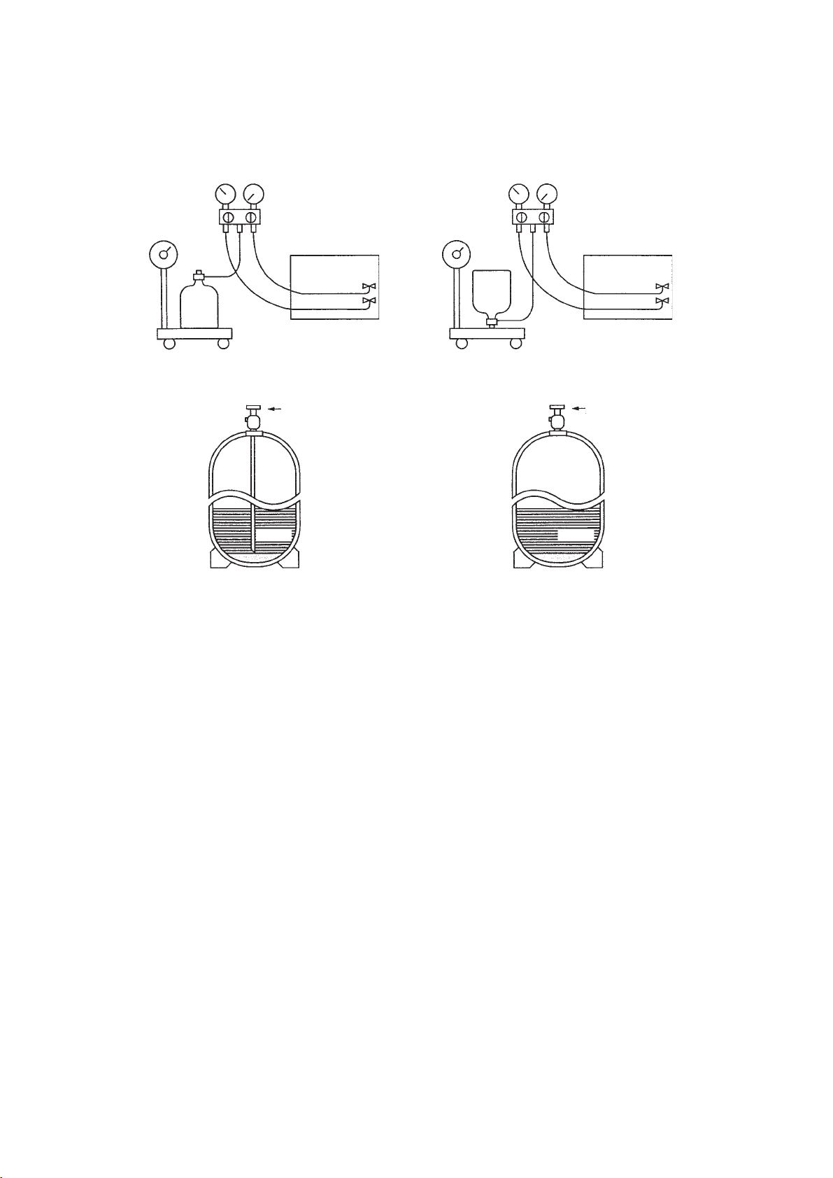
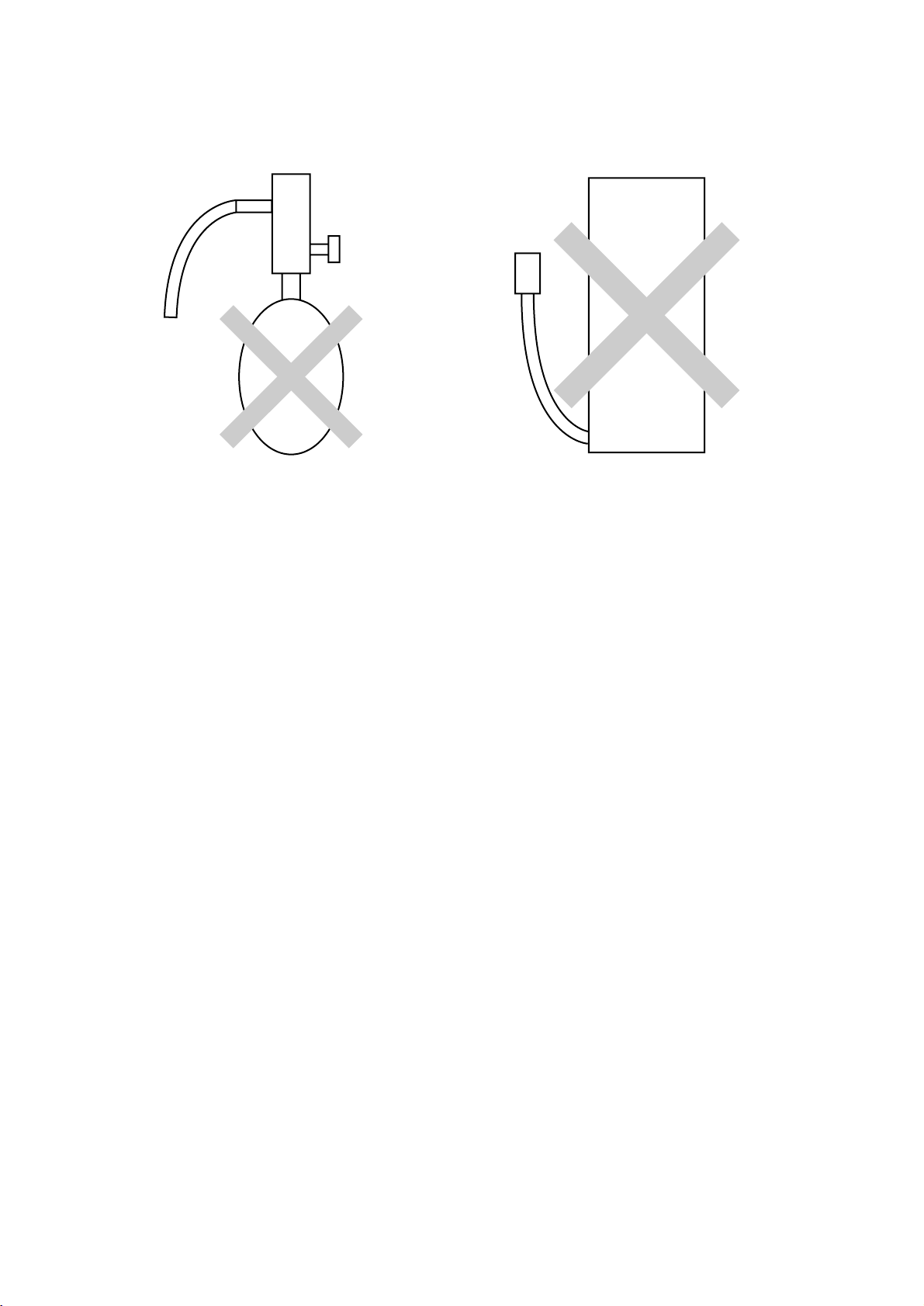
[7] Charging of Refrigerant
R407C must be in a liquid state when charging, because it is a non-azeotropic refrigerant.
For a cylinder with a syphon attached For a cylinder without a syphon attached
Cylin-
Cylin-
der
Cylinder color identification R407C-brown Charged with liquid refrigerant
der
Valve
Liquid
Valve
Liquid
Reasons :
1. R407C is a mixture of 3 refrigerants, each with a different evaporation temperature. Therefore, if the equipment is
charged with R407C gas, then the refrigerant whose evaporation temperature is closest to the outside temperature is
charged first while the rest of refrigerants remain in the cylinder.
Note :
• In the case of a cylinder with a syphon, liquid R407C is charged without turning the cylinder up side down. Check the
type of cylinder before charging.
[8] Dryer
1. Replace the dryer when the refrigerant circuit is opened (Ex. Change the compressor, full gas leakage). Be sure to
replace the dryer with a CITY MULTI Series WR2 (PQRY) (For use with R407C).
If any other product is used, the unit will be damaged.
2. Opening the refrigerant circuit after changing to a new dryer is less than 1 hour. The replacement of the dryer should
be the last operation performed.
–7–
Page 11
22
2 COMPONENT OF EQUIPMENT
22
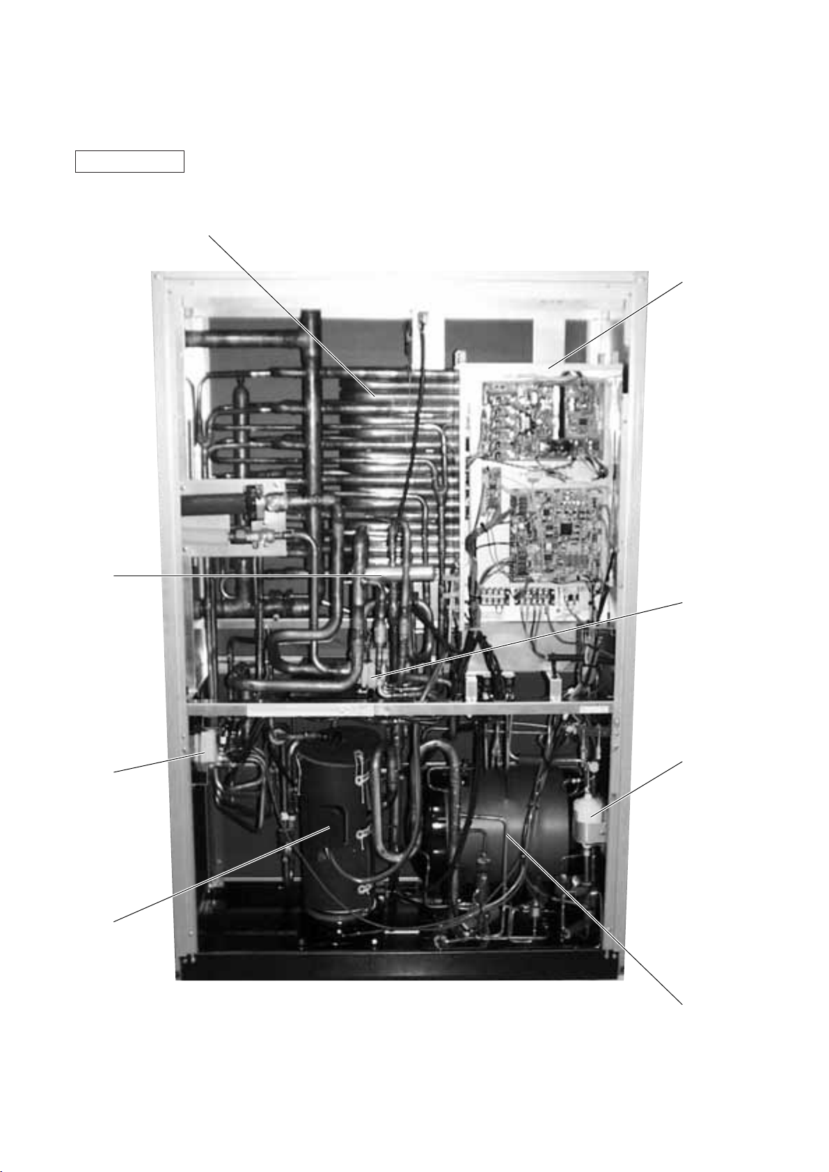
[1] Appearance of Components
Heat source unit
Heatexchanger
Control Box
4-way
Valve
SV
Block
Compressor
CV
Block
Drier
–8–
Accumulator
Page 12
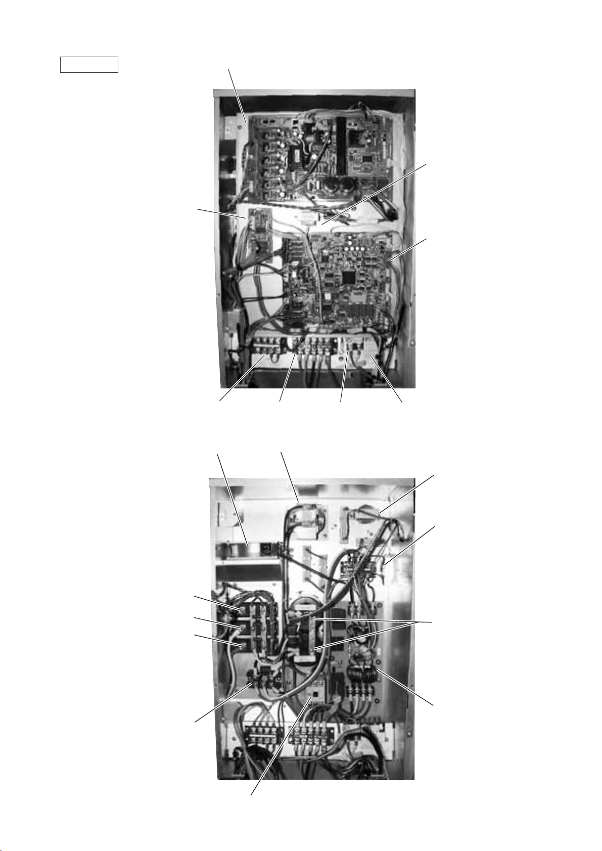
Control Box
Front View
INV board
Transformer
(T01)
RELAY
board
MAIN
board
Inner View
Terminal block TB8
UNIT ON/OFF,
Pump inter lock
Cooling fan
(MF1)
Transistor
Module
TRM3
TRM2
TRM1
Terminal block TB1A
Power Source
DC reactor
(DCL)
Terminal block TB3
Transmission
Terminal block TB7
Transmission (Centralized Control)
Choke coil
(L2)
Fuse
(F3)
Capacitor
(C2, C3)
Diode
stack
(DS)
Magnetic Contactor (52C)
Noise
Filter
–9–
Page 13
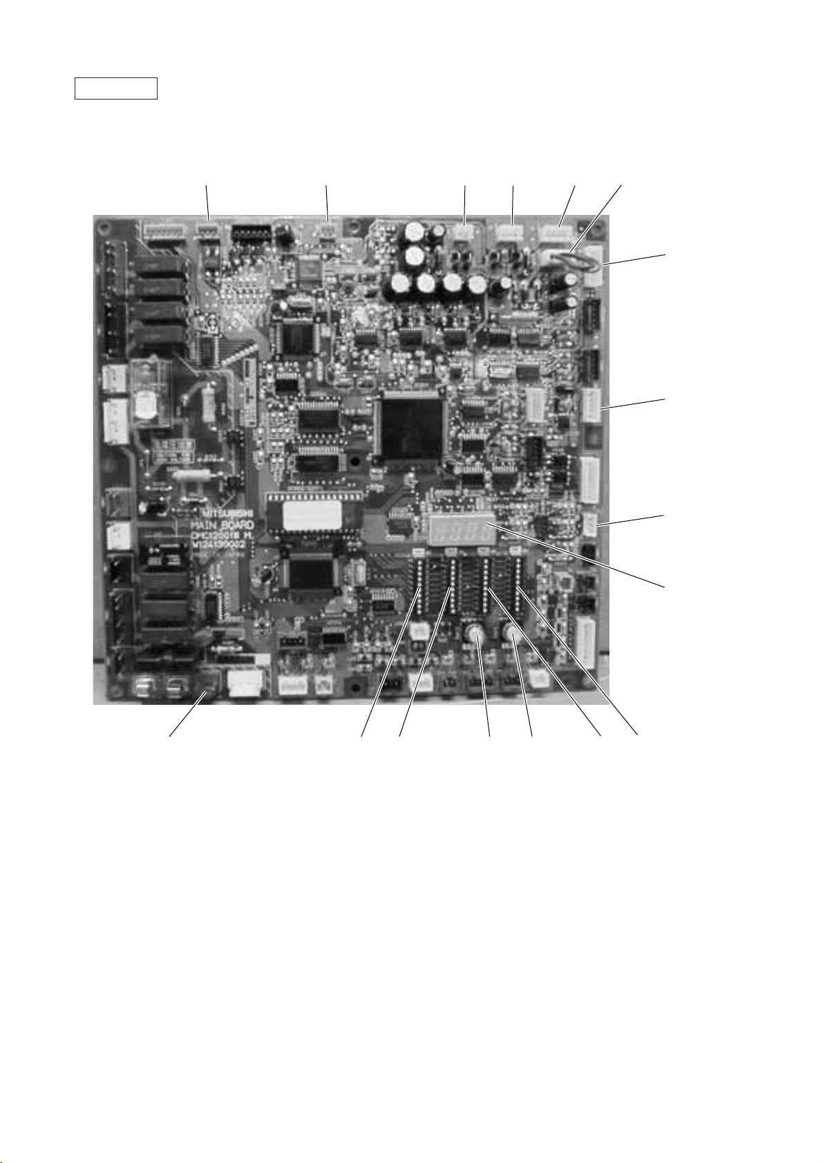
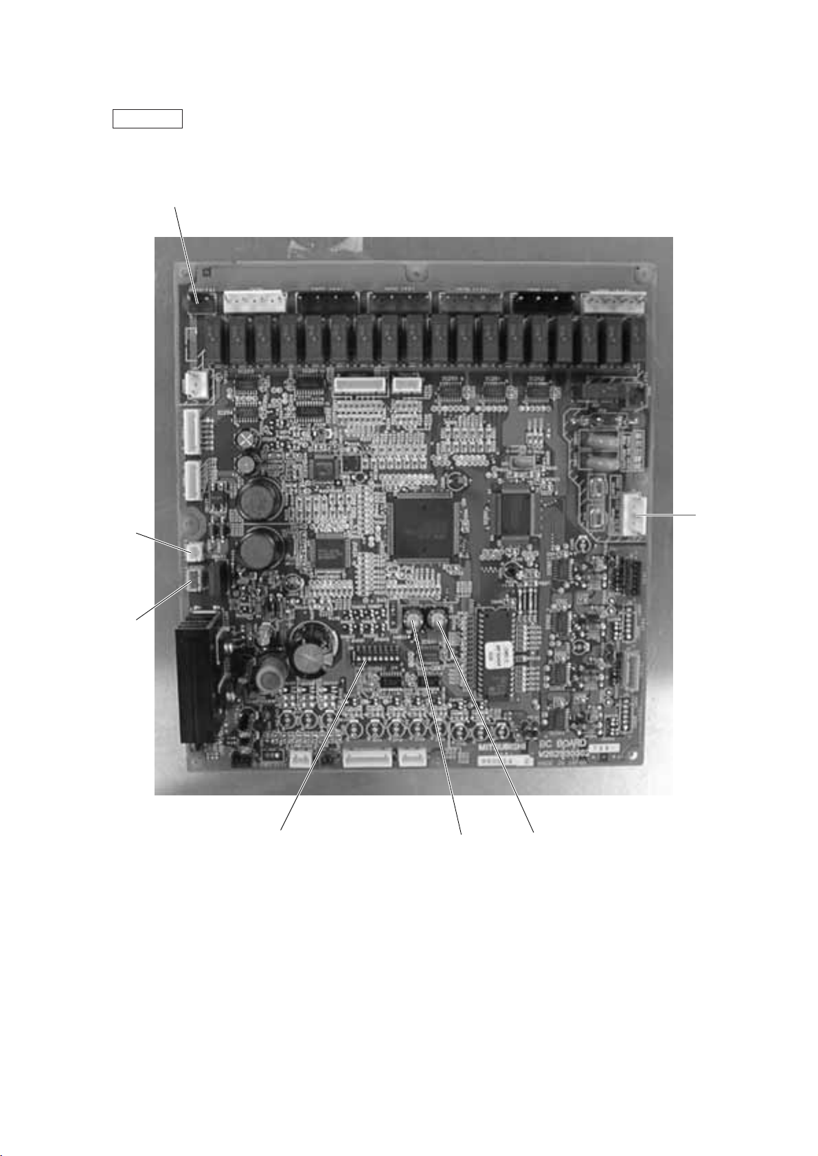
MAIN board
CNTR CNVCC4 CNS1 CNS2 CN40 CN41
Power source
for control (5V)
CNVCC3
Power source
for control
1-2 30 V,
1-3 30 V,
4-6 12 V,
5-6 5 V
CN51
CN3D
LD1
Service LED
SW3SW4CN20
SWU1SWU2
SW1SW2
–10–
Page 14
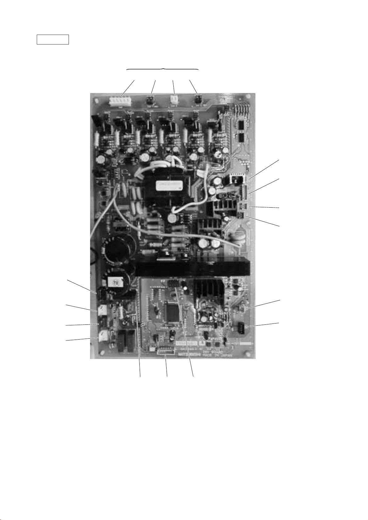
INV board
Output to transistor module
CN3 CN2-1 CN2-2 CN2-3
CNVCC2
Power supply (5V)
CNVCC1
Power supply
1-2 30 V, 1-3 30 V,
4-6 12 V, 5-6 5 V
CNL2
CNVDC
CN52C
CNFAN
CNAC2
Power source
1 L2
3 N
CN30V
CNTH
CNCT
CNR CNRS2 SW1
–11–
Page 15
RELAY board
–12–
Page 16
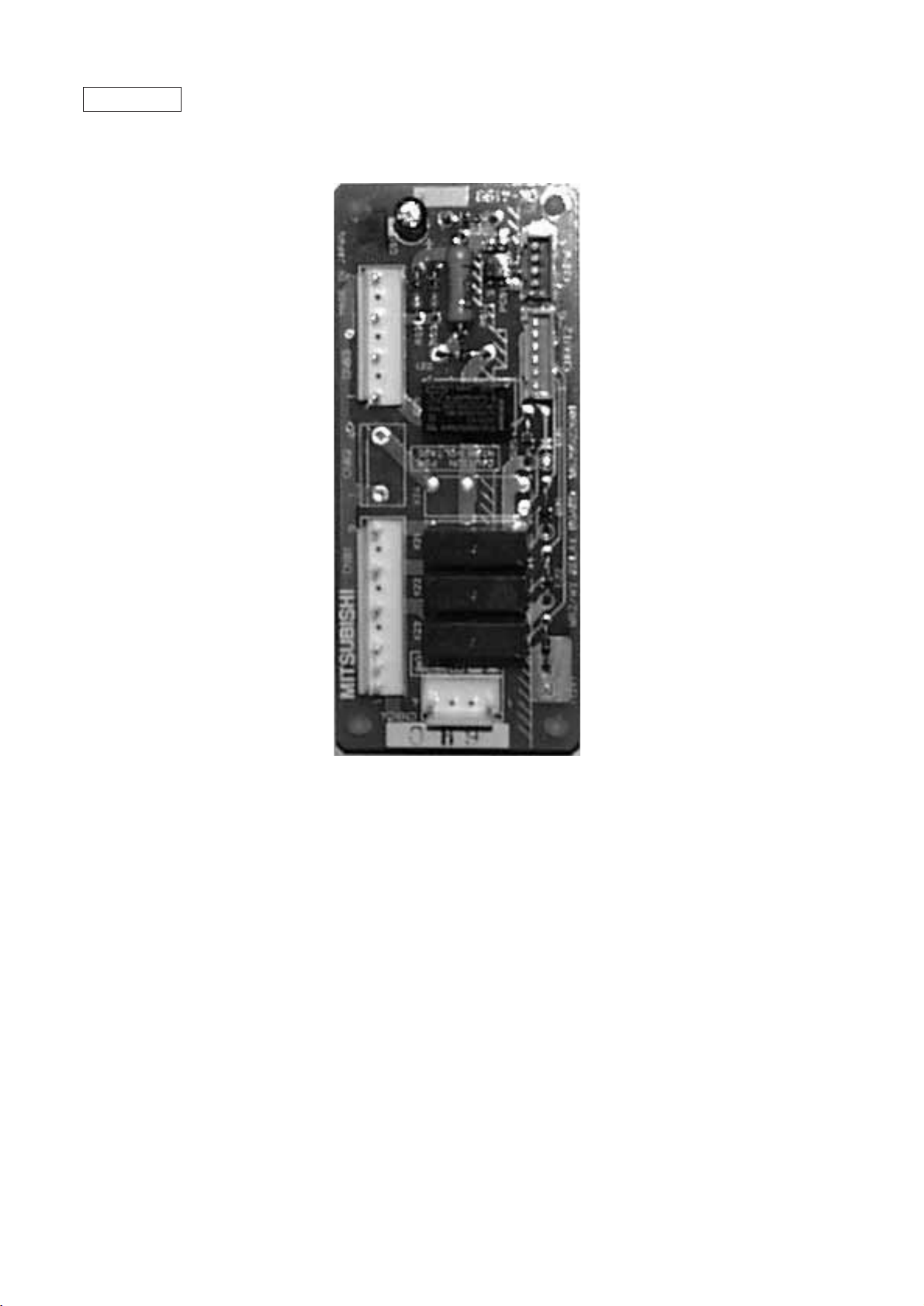
BC controller
BC board
CNTR
CN02
M-NET
transmission
CN03
CN12
Power
supply
1 EARTH
3 N
5 L
SW4 SW2 SW1
–13–
Page 17
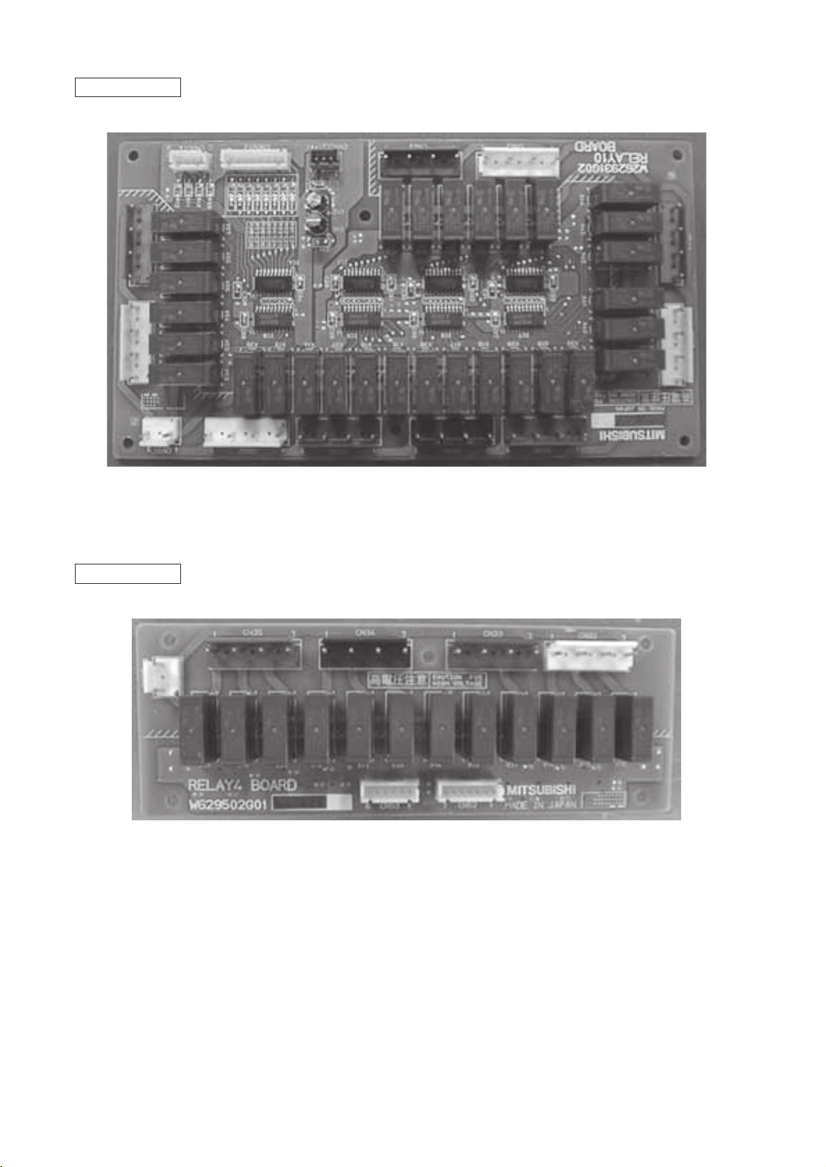
RELAY 10 board
RELAY 4 board
–14–
Page 18
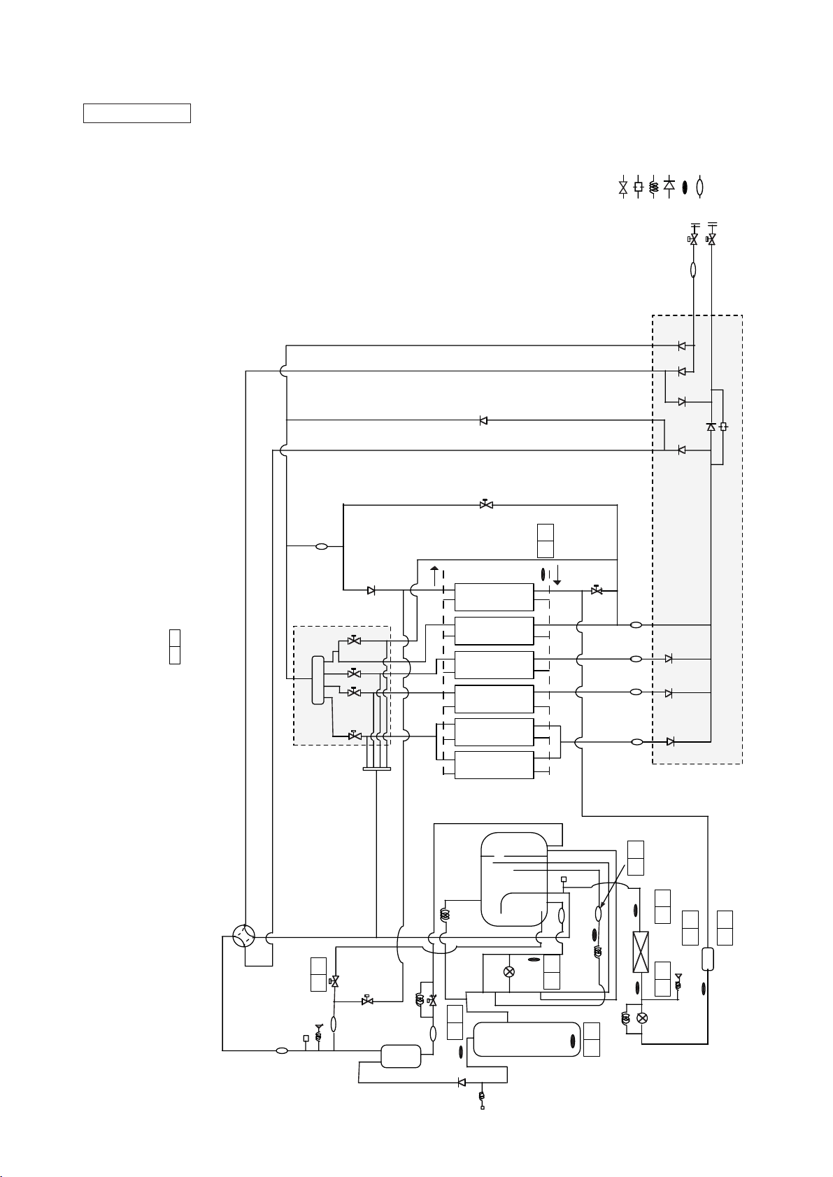
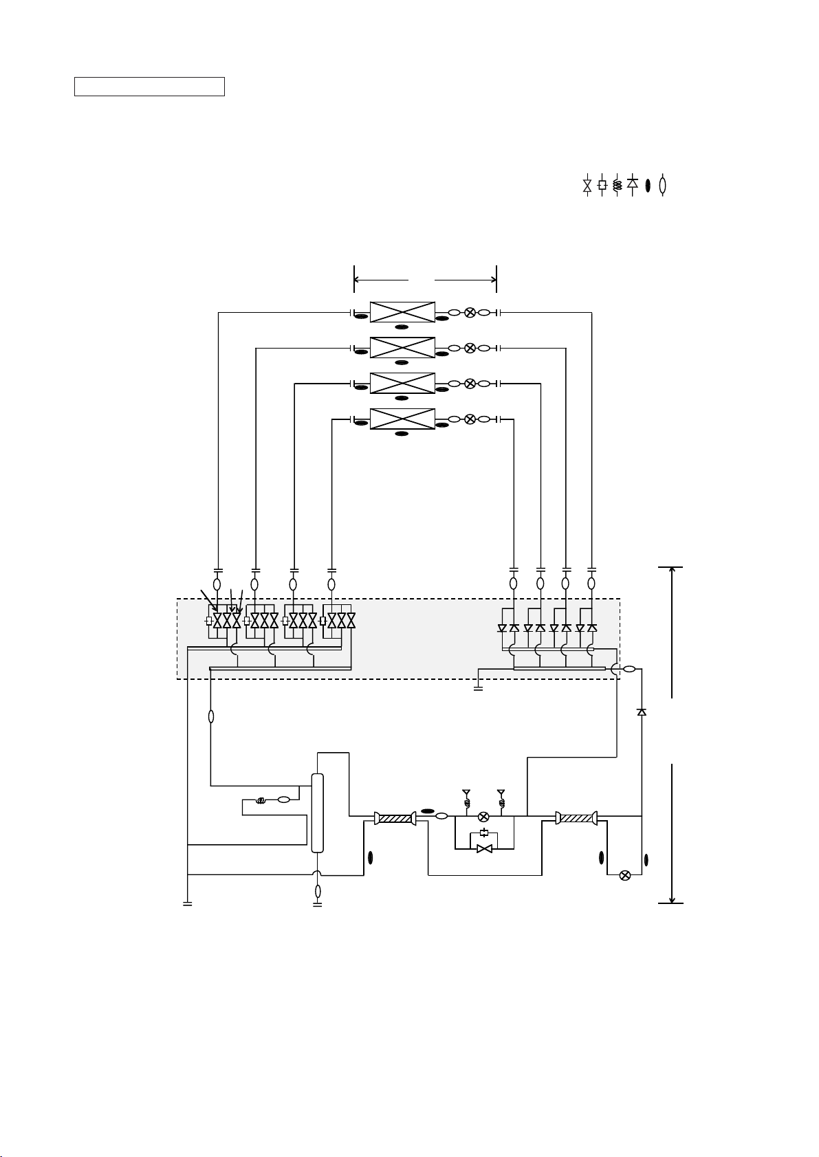
[2] Refrigerant Circuit Diagram and Thermal Sensor
: Solenoid valve
: Orifice
: Capillary
: Check valve
: Thermal sensor
: Strainer
SP : Service port
ACC : Accumulator
Heat source unit
/h
3
Pipe length 10m
Indoor capacity 100%
TH10, THINV
˜
: MPa for 63HS, 63LS
Heating : Indoor 21/– Inlet water 20˚C
CH
*Operation data of PQRY-P250YMF-B
*Operation Condition Cooling : Indoor 27/19.5 Inlet water 30˚C Water volume 4.93m
*
Standard operation data are shown for cooling
in the C column and heating in the H column.
Units for each balue are : ˚C for TH1
ST8
SV6
Distributor
SV4
SV3
CV11
SV5
CV7
SV72
30 20
TH6
Water
Water heat exchanger
(Double coil type)
SV71
ST7d
ST7b ST7cST7a
BV1
CV3
CV10
CV9
CV8
ST1
CV2
CV5
CV4
CV6
BV2
Orifice
Water
circulating
Solenoid Valves
Block
4way valve
ST2
SP1
2.2
2.15
63HS
SV2
ST5
SV73
CP1
Oil
separator
ST6
CP3
SV1
99.0 79.0
TH1
Accumulator
SLEV
TH3
SP2
ST3
9.0
23.5
TH10
ST4
TH4
CP2
CP4
78 60
30.0 29.0
TH INV
6.2 6.54.3 5.0
0.50 0.54
63LS
Cooling INV HEX
TH2
TH9
LEV2
Check Valves Block
32.0 22.0
Drier
Compressor
CV1
63H
–15–
Page 19
: Solenoid valve
: Orifice
: Capillary
: Check valve
: Thermal sensor
: Strainer
SP : Service port
ACC : Accumulator
BC controller, Indoor unit
Indoor
units
SVC
Valves Block
SVA
SVB
TH23
TH21
TH11
TH22
PS1
LEV
LEV1
PS3
BC controller
CMB-P104V-E
Gas/liquid separator
TH12
SVM
TH15
LEV3
TH16
–16–
Page 20
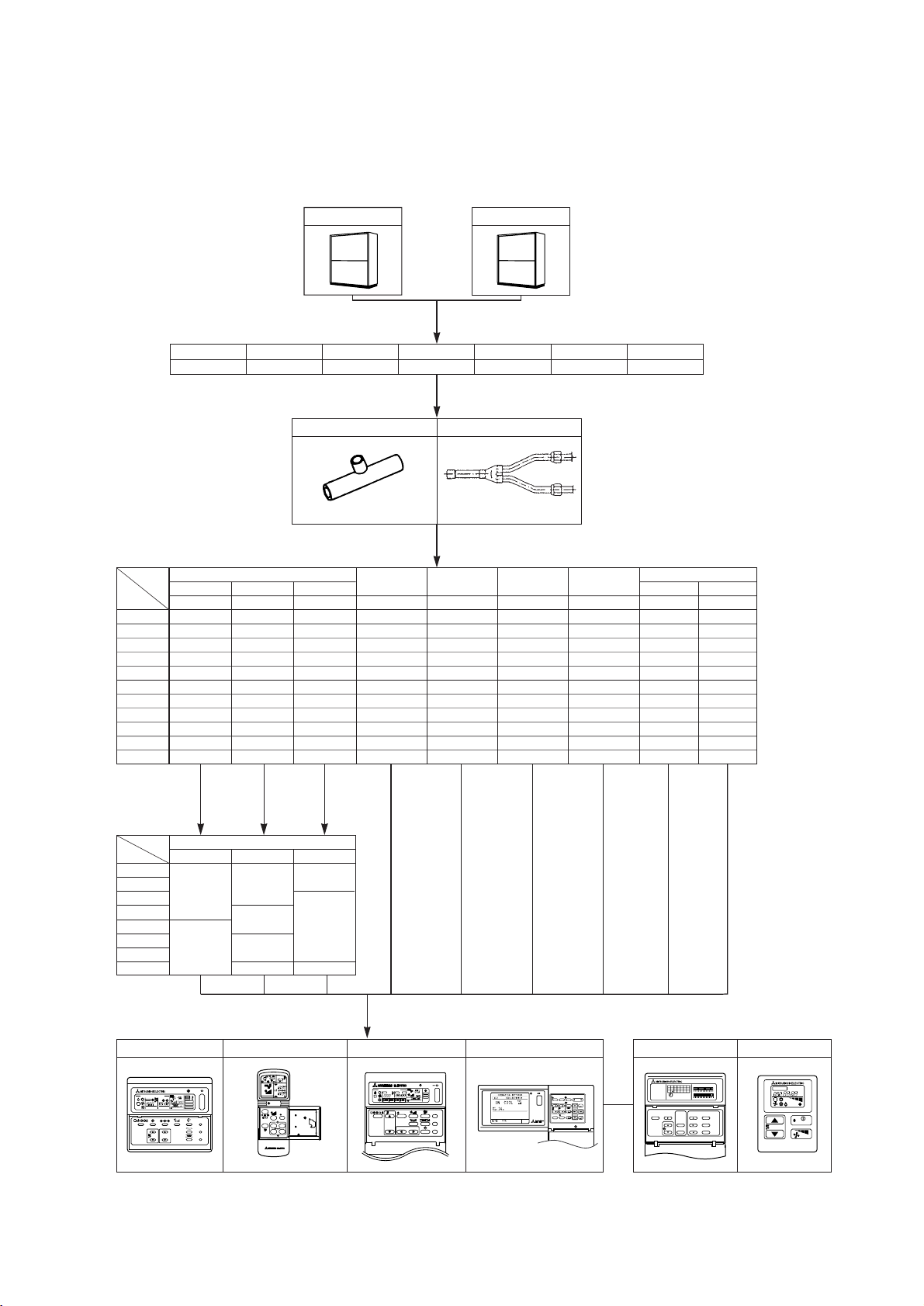
[3] Equipment Composition
A. Heat source unit
PQRY-P200YMF-B
PQRY-P250YMF-B
B. BC controller
4-branch type 5-branch type 6-branch type 8-branch type 10-branch type 13-branch type 16-branch type
CMB-P104V-E CMB-P105V-E CMB-P106V-E CMB-P108V-E CMB-P1010V-E CMB-P1013V-E CMB-P1016V-E
C. Branch pipe kit/joint pipe kit
Branch pipe kit
CMY-Y102S-F CMY-Y102L-F
Joint pipe kit
CMY-R160-G: for V-E type
D. Indoor unit
20VMB
25VBM
32VBM
40VBM
-
-
-
-
-
-
-
Cassette ceiling
-
80VLMD
100VLMD
125VLMD
Ceiling
4-way flow2-way flow
concealed
PLFY-PPLFY-P PEFY-P PKFY-P PCFY-P PFFY-P PFFY-P
Ceiling mounted
built-in
PDFY-P
Wall mounted
Ceiling
suspended
20VM
25VM
32VM
40VM
50VM
63VM
-
80VKM
100VKM
125VKM
71VMH
80VMH
100VMH
125VMH
71VM
80VM
100VM
125VM
-
-
-
-
-
100VGM
125VGM
-
Model
1-way flow
Capacity
PMFY-P
20 -20VLMD 20VML 20VAM - 20VLEM 20VLRM
25 -25VLMD 25VML 25VAM - 25VLEM 25VLRM
32 32VKM32VLMD 32VML 32VGM - 32VLEM 32VLRM
40 40VKM40VLMD 40VMH 40VGM 40VGM 40VLEM 40VLRM
50 50VKM50VLMD 50VMH 50VGM - 50VLEM 50VLRM
63 63VKM63VLMD 63VMH - 63VGM 63VLEM 63VLRM
71
80
100
125
140 -- 140VMH - - - -
Floor standing
Exposed Concealed
--
-
-
-
-
-
-
E. Option (panel)
Model
Capacity
20
25
32
40
50
63
80
100, 125
Decoration panel
PMP- CMP-
40MB
32LW-F
40LW-F
-
63LW-F
125LW-F
PLP-
-
3GB
6GB
F. Remote controller
PAR-F25MA MJ-103MTRAPAC-FL31MA PAC-SC30GRA PAC-SC32PTA PAC-SE51CRA
CHECK
TEST RUN
STAND BY
DEFROST
NETWORK
REMOTE CONTROLLER
PAR-F25MA
CENTRALLY CONTROLLED
CHECK
INDOOR UNIT
ADDRESS NO.
TEMP. TIMER SET
˚C
ON OFF
CLOCK
ERROR CODE
OA UNIT ADDRESS NO.
˚C
AM
–
ON/OFF
1Hr.
˚C
FILTER
CHECK MODE
TEST RUN
NOT AVAILABLE
ON OFFCLOCK
FILTER
CHECK
TEST RUN
PM
AM
PM
NOT AVAILABLE
ON/OFF
MODE
CLOCK
FAN
VANE
STOP
START
MIN.
HR.
COLLECTIVE
GROUP
GROUP
REMOTE CONTROLLER
PAC-SC30GRA
CENTRALLY CONTROLLED
ADDRESS
CHECK
˚C
ON/OFF
˚C
OFF
ON
FILTER
CHECK MODE
TEST RUN
NOT AVAILABLE
ON/OFFTEMP.
FILTER
CHECK
GROUP
TEST RUN
ON/OFF
CENTRAL CONTROLLER
TEST RUN
ON/OFF
FAN SPEED
MODE
GROUP
123
SELECT
AIR
DIRECTION
BACK
SCREEN
6
54
CLOCK/
TEMP.
VENTILATION
PATTERN
INS.
9
87
TIMER
REMOTE
RESET
MODE
PROHIBITION
ENTER
MJ-103MTRA
0
DEL.
PROGRAM TIMER
PAC-SC32PTA
SET
SET/MONITOR TODAY
SMTWTFS
CLOCK
SET BACK
036912
12 15 18 21 24
WEEKLY
DAILY
SET BACK ON
SETTING
SETTING
ON
SET BACK
DAILY TIMER
OFF
OFF
–17–
TEMP.
CENTRAL
TEMP.CHECK
ON/OFF
PAC-SE51CRA
˚C
Page 21
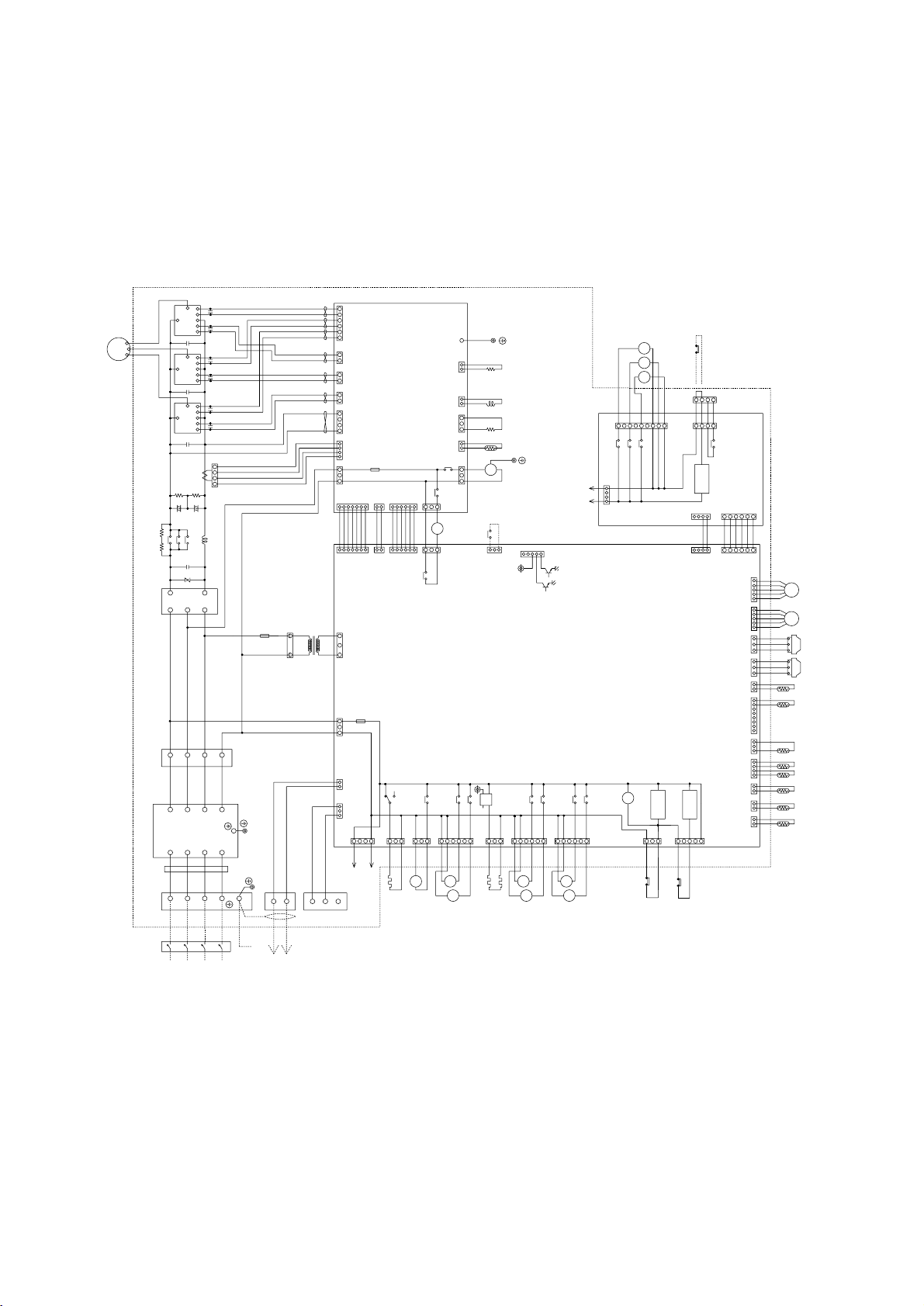
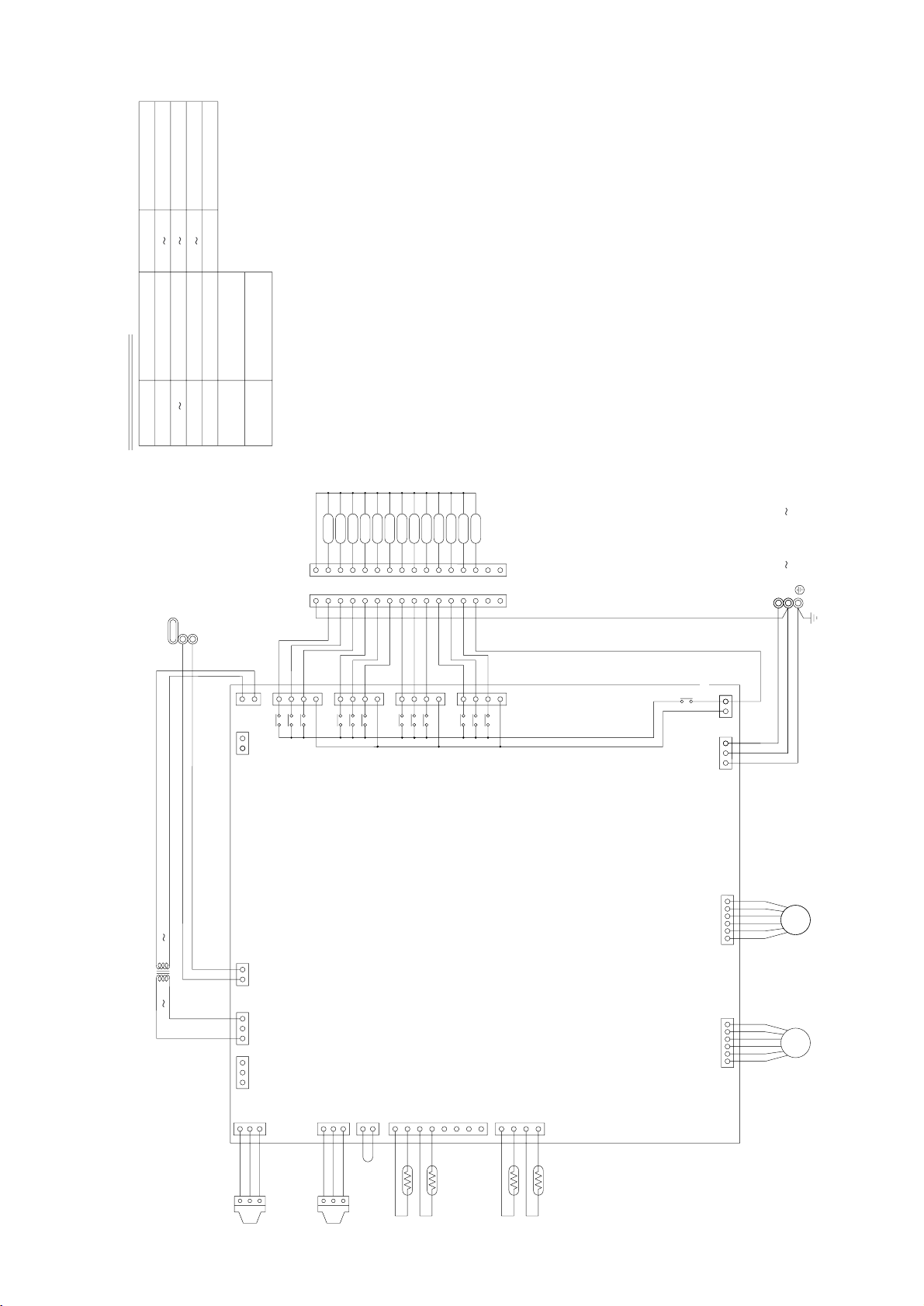
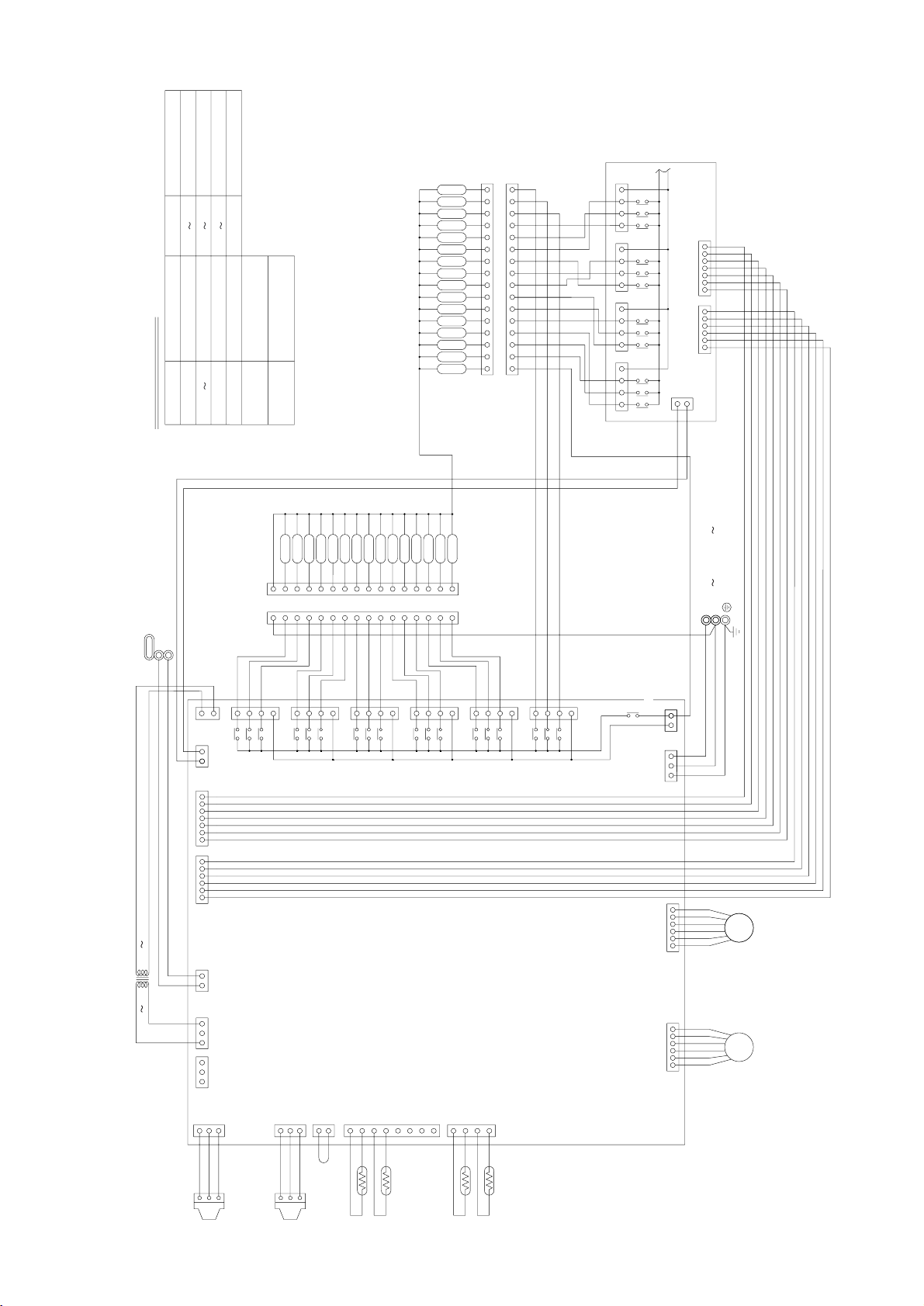
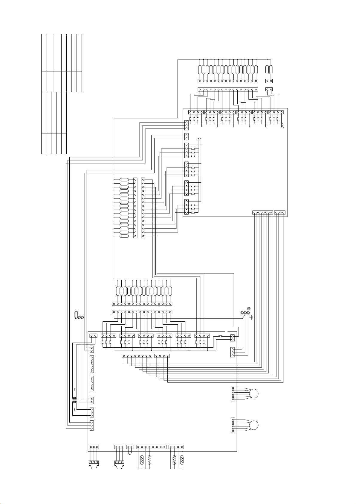
[4] Electrical Wiring Diagram
<ELECTRICAL WIRING DIAGRAM>
Refer to the [6]
the switch operations.
L2
S
M2
M1
L1
1
L3
PE
R6
5
243
32
4
1123 67
181221123712631523445312
234
1
5
56123
F01
250VAC
2A F
3
CN33
(3P)
1
1
3
CN20
(3P)
223
221
131
CNS1
(2P)
CNAC2
(3P)
CNCT
(4P)
CNVDC
(4P)
2
CNS2
(3P)
1
CNX10
(3P)
CNR
(3P)
2
CN52C
(3P)
3
CNTH
(2P)
X02
X01
N
N
L3
SV1
LEV2
CH1
TB1A
L2
F1
250VAC
2A F
123
TH1
TH2
Black
White
Red
63HS
123
Black
White
Red
63LS
L1
SLEV
PE
White
Red
Black
Blue
Green/
Yellow
TB3
M1
M2
TB7
~
DS
C1
~-
~
+
ZNR4
C1
R5
R1
52C
+
TRM1
+
DCL
C2
C3
R2
R3
T01
F3
250VAC
1A F
CNTR1
TRM2
C1
C2E1
B2
E2
E2
E1
B1
B1
E1
E2
E2
B2
C2E1
C1
TRM3
C2E1
B2
E2
E2
E1
B1
C14
C15
C16
43
DCCT
21
White
C25
U
C22C21
C24C23
C20
W
MC1
V
Motor
(Compressor)
Red Black
3
21
FG
12
2
34
1
12
2
34 2
13
12
2
12
1
11
2
23
1
45
3
6
2
2341217654321
56123
52C
X02
X01
X10
CNVCC1
(6P)
CNVCC2
(6P)
CNVCC3
(6P)
CNVCC4
(2P)
CNRS3
(7P)
CNRS2
(7P)
CNFAN
(3P)
THHS
CNH
(3P)
CNL
(3P)
CN2-1
(2P)
CN2-2
(2P)
CN2-3
(2P)
CN3
(6P)
CN32
(3P)
CNLV1
(5P)
CNTR
(3P)
CNLV2
(5P)
CNL2
(2P)
CN30V
(2P)
MF1
Purple
R7
Black
Yellow
Orange
L2
Power circuit board
(INV board)
BOX BODY
Red
Brown
Black
Purple
Black
Yellow
White
Red
Brown
Orange
Red
Blue
34251
CN51
(5P)
12V
5 : DIP SW3-3 OFF : water freeze signal
ON : trouble signal
4 : Compressor ON/OFF
Control circuit board
(MAIN board)
TH10THINV
CN12
(2P)
CN09
(2P)
CN06
(2P)
CN05
(4P)
CN03
(3P)
CN02
(8P)
CN01
(2P)
CNOUT1
(6P)
12
TH9
CNRT1
(5P)
54321
12
65432
1
X08
X09
CN36
(6P)
CN37
(6P)
CN38
(3P)
65432
1
X06
X07
TH4 TH3 TH6
63H
CH3
CH2
SV2
21S4
X05
X04
SSR
12
34
X10
321
123123456
CN34
(6P)
CN35
(3P)
432121
BOX BODY
BOX BODY
TB1B
NF
Red
White
Black
Blue
Red
White
Black
Blue
L1
L2
L3
N
L1
L2
L3
N
L1
L2
L3
N
65432
1
detection
circuit
SV4
SV3
SV6
SV5
CN63PW
(4P)
432
1
321
4
CNAC3
(4P)
AC1
AC4
(to CNAC4)
26W
detection
circuit
RELAY board
(to CNAC3)
AC4 AC1
65432
1
CNOUT2
(6P)
63PW
TB8
123
4
circuit
detection
X25
CN83
(7P)
753
1
SV73
SV71
SV72
X23
X22
X21
98765
CN81
(9P)
432
1
CNAC4
(4P)
4
32 1
123
4
CNPW
(4P)
Noise
Filter
Diode
stack
Code heater
(Accumulator liquid
level detect)
High pressure
switch
Freeze protect
switch
Pump
interlock
BOX BODY
132
CN3D
(3P)
DEMAND
Unit ON/OFF
FB1
Inverter
Controller Box
Terminal
Block
Terminal
Block
Power source
3N~
380/400/415V
50/60Hz
Connect to
Indoor and
remote controller
Crank case heater
(Compressor)
• PQRY-P200·250YMF-B
–18–
Page 22
SV1, SV2
4-way valve
Solenoid valve (Discharge-suction bypass)
21S4
Aux. relay
Discharge pipe temp. detect
Saturation evapo. temp. detect
X1,2,4~10
X21~23,25
Electronic expansion valve
(Heat exchanger for inverter)
Electronic expansion valve (Oil return)
High pressure sensor
Low pressure sensor63LS
63HS
SLEV
LEV2
Solenoid valve
(Heat exchanger capacity control)
Solenoid valve
(Heat exchanger capacity control)
SV71~73
SV3~6
Solid state relaySSR
Varistor
Name
Symbol
DCL
(Power factor improvement)
<Symbol explanation>
DC reactor
DCCT Current Sensor
ZNR4
FB1 Ferrite core
Radiator panel
52C
MF1
Magnetic contactor
(Inverter main circuit)
Chock coil (Transmission)
Diode stack
Power transistor module
Niose FilterNF
TRM1~3
DS
L2
OA temp. detect
High pressure liquid temp.
Compressor shell temp.
Radiator panel temp. detect
Outlet temp. detect of
heat exchanger for inverter
Lower
Upper
Accumulator liquid
temp. detect
Thermistor
THHS
TH10
TH9
TH6
TH4
TH3
TH2
TH1
THINV
Earth terminal
21S4
SV1
SV2
SV3
SV4
SV72SV71SV5
SV6
SV73
SSR
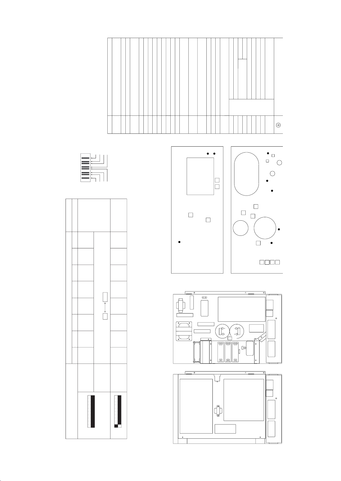
<Unit internal layout>
(Upside) (Underside)
<Controller box internal layout>
<Operation of self-diagnosis switch (SW1) and LED display>
<LED display>
SV3
SV4
SV5
SV6
TH6
THINV
TH2
21S4
26W
INVERTER
SV72 SV71
OIL
MC
ACCUMULATOR
TH9
LEV2
SLEV
TH4
TH3
SV1
SV73
SV2
63H
TH1
TH10
63HS
63LS
CONTROLLER
BOX
SEPARATOR
(Underside)
(Upside)
C2
DCCT
R3
R2
ZNR4
C1
DS
THHS
DCL
R5
R1
R6
L2
R7
F3
C3
NF
TB7
TB3
TB1A
TB8
52C
TB1B
MF1
TRM1
TRM2
TRM3
RELAY
board
T01
MAIN board
INV board
TB7
TB3
TB8
TB1A
Display
Relay output
display
(Lighting)
Check display1
(Blinking)
(at factory shipment)
Display at LED lighting (blinking) Remarks SW1 operation
FLAG1 FLAG2 FLAG3 FLAG4 FLAG5 FLAG6 FLAG7 FLAG8
Display the address and error code by turns
Always
lighting
FLAG8 always lights
at microcomputer
power ON
During
compressor
run
Crankcase
heater
51
1102
FLAG1
FLAG2
FLAG3
FLAG4
FLAG8
FLAG7
FLAG6
FLAG5
ON:1
OFF:0
1 2 3 4 5 6 7 8 9 10
ON:1
OFF:0
1 2 3 4 5 6 7 8 9 10
* please refer to the service handbook about other switch settings of LED display.
LD1
• PQRY-P200·250YMF-B
–19–
Page 23
Symbol explanation
PE
3
2
1
3
2
1
EARTH
Terminal block
(for Transmission)
TB02
Terminal block
(for power source)
TB01
Note:TB02 is terminal block for transmission.
Never connect power line to it.
NameSymbol
Solenoid valve
Solenoid valve
Solenoid valve
Solenoid valve
Expansion valve
Thermister sensor
Transformer
NameSymbol
SV1 4A
SV1 4B
SV1 4C
SVM
TR
TH11 16
LEV1,3
PS1,3 Pressure sensor
Transmission line
Shield wire
/N 220V 240V 50Hz
Power source
BC Board
31
LEV1
TB01
16
15
14
13
12
11
10
9
8
7
6
5
4
3
2
1
16
15
14
13
12
11
10
9
8
7
6
5
4
3
2
1
SVM
SV4B
SV4A
SV4C
SV3B
SV3A
SV3C
SV2B
SV2A
SV2C
SV1C
SV1A
SV1B
}
CN38
3
1
CNTR
CN02
CN12
153
31
7
5
3
1
7
5
3
1
7
5
3
1
7
5
3
1
TR
3
CNVCC1
12
X2
X1
X30
X4
X3
X31
X6
X5
X32
X8
X7
X33
X21
}
DC 30V
654321654321
LEV3
1
2
3
CNP1
1
2
3
CNP3
2
1
1
2
3
4
5
6
7
8
4
3
2
1
12321
CN03
CN13
CN10
CN11
CN07 CN05
L
N
TH11
TH12
TH15
TH16
PS1
PS3
20 22V
TB02
M2
M1
CN26
CN27
CN28
CN29
TB01
220 240V
CN36
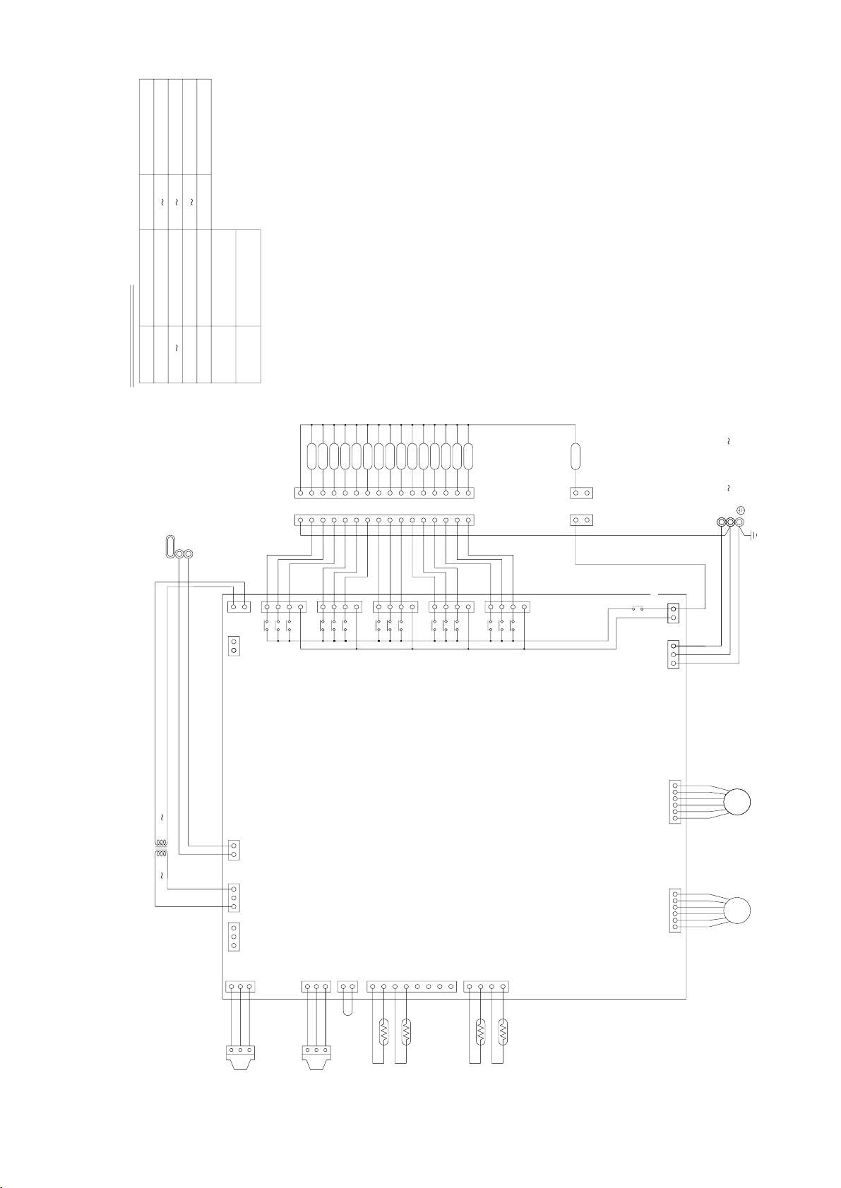
• CMB-P104V-E
–20–
Page 24
Symbol explanation
PE
3
2
1
3
2
1
EARTH
Terminal block
(for Transmission)
TB02
Terminal block
(for power source)
TB01
Note:TB02 is terminal block for transmission.
Never connect power line to it.
NameSymbol
Solenoid valve
Solenoid valve
Solenoid valve
Solenoid valve
Expansion valve
Thermister sensor
Transformer
NameSymbol
SV1 5A
SV1 5B
SV1 5C
SVM
TR
TH11 16
LEV1,3
PS1,3 Pressure sensor
Transmission line
Shield wire
/N 220V 240V 50Hz
Power source
BC Board
31
LEV1
TB01
16
15
2
1
2
1
14
13
12
11
10
9
8
7
6
5
4
3
2
1
16
15
14
13
12
11
10
9
8
7
6
5
4
3
2
1
SV4B
SV4A
SV4C
SV3B
SV3A
SV3C
SV2B
SV2A
SV2C
SV1C
SV1A
SV1B
}
CN38
3
1
CNTR
CN02
CN12
153
31
7
5
3
1
7
5
3
1
7
5
3
1
7
5
3
1
TR
3
CNVCC1
12
X2
X1
X30
X4
X3
X31
X6
X5
X32
X8
X7
X33
X21
}
DC 30V
654321654321
LEV3
1
2
3
CNP1
1
2
3
CNP3
2
1
1
2
3
4
5
6
7
8
4
3
2
1
12321
CN03
CN13
CN10
CN11
CN07 CN05
L
N
TH11
TH12
TH15
TH16
PS1
PS3
20 22V
TB02
M2
M1
CN26
CN27
CN28
CN29
TB01
220 240V
SV5C
SV5A
SV5B
7
5
3
1
X10
X9
X34
CN30
SVM
CN36
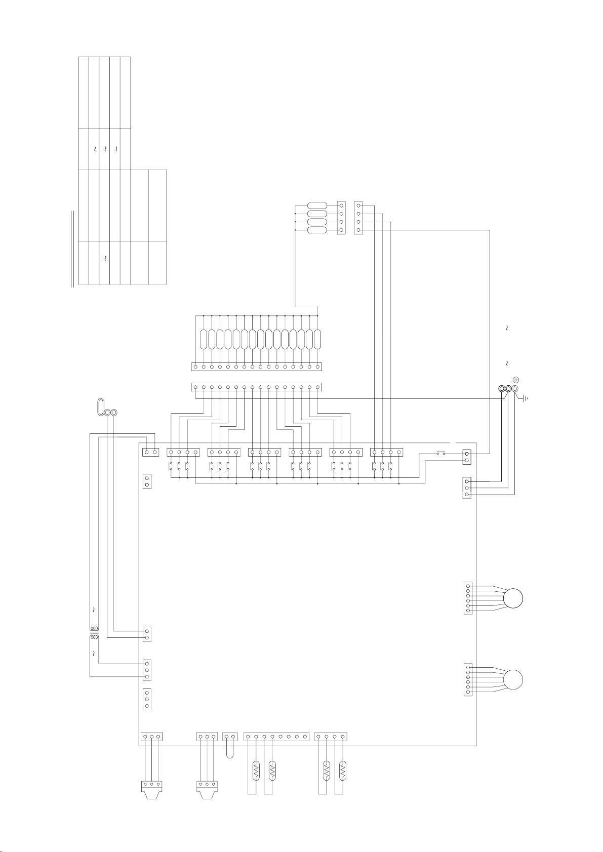
• CMB-P105V-E
–21–
Page 25
PE
3
2
1
3
2
1
EARTH
Note:TB02 is terminal block for transmission.
Never connect power line to it.
Transmission line
Shield wire
/N 220V 240V 50Hz
Power source
BC Board
31
LEV1
TB01
SV6B
SV6A
SV6C
16
15
14
13
12
11
10
9
8
7
6
5
4
3
2
1
16
15
14
13
12
11
10
9
8
7
6
5
4
3
2
1
SV5C
SV5A
SV5B
SV4B
SV4A
SV4C
SV3B
SV3A
SV3C
SV2B
SV2A
SV2C
SVM
SV1C
SV1A
SV1B
}
4321
1234
CN38
3
1
CNTR
CN02
CN12
153
31
7
5
3
1
7
5
3
1
7
5
3
1
7
5
3
1
7
5
3
1
7
5
3
1
TR
3
CNVCC1
12
X2
X1
X30
X4
X3
X31
X6
X5
X32
X8
X7
X33
X10
X9
X34
X12
X11
X35
X21
}
DC 30V
654321654321
LEV3
1
2
3
CNP1
1
2
3
CNP3
2
1
1
2
3
4
5
6
7
8
4
3
2
1
12321
CN03
CN13
CN10
CN11
CN07 CN05
L
N
TH11
TH12
TH15
TH16
PS1
PS3
20 22V
TB02
M2
M1
CN26
CN27
CN28
CN29
CN30
CN31
TB01
220 240V
CN36
Symbol explanation
Terminal block
(for Transmission)
TB02
Terminal block
(for power source)
TB01
NameSymbol
Solenoid valve
Solenoid valve
Solenoid valve
Solenoid valve
Expansion valve
Thermister sensor
Transformer
NameSymbol
SV1 6A
SV1 6B
SV1 6C
SVM
TR
TH11 16
LEV1,3
PS1,3 Pressure sensor
• CMB-P106V-E
–22–
Page 26
PE
3
2
1
3
2
1
EARTH
}
Power source
}}
L
N
Power source
/N 220V 240V 50Hz
Note:TB02 is terminal block for transmission.
Never connect power line to it.
Transmission line
Shield wire
SVM
BC Board
CN38
1
3
1
CNTR
CN50
CN51
7654321123456
CN02
CN12
153
31
7
5
3
1
7
5
3
1
7
5
3
1
7
5
3
1
7
5
3
1
7
5
3
1
3
TR
3
CNVCC1
12
X2
X1
X30
X4
X3
X31
X6
X5
X32
X8
X7
X33
X10
X9
X34
X12
X11
X35
X21
}
DC 30V
654321654321
LEV3 LEV1
1
2
3
CNP1
1
2
3
CNP3
2
1
1
2
3
4
5
6
7
8
4
3
2
1
123
21
CN03
CN13
CN10
CN11
CN07 CN05
CN36
TH11
TH12
TH15
TH16
PS1
PS3
20 22V
TB02
M2
M1
CN26
CN27
CN28
CN29
CN30
CN31
TB01
220 240V
LEV1
7654321
TB01
SV6B
SV6A
SV6C
16
15
14
13
12
11
10
9
8
7
6
5
4
3
2
1
16
15
14
13
12
11
10
9
8
7
6
5
4
3
2
1
RELAY4 Board
SV5C
SV5A
SV5B
SV4B
SV4A
SV4C
SV3B
SV3A
SV3C
SV2B
SV2A
SV2C
CN32
CN33
CN39
3
1
SV7C
SV7A
SV7B
SV8C
SV8A
SV8B
SV1C
SV1A
SV1B
X14
X13
X36
X37
X15
X16
98765432116 15 1011121314
12345678910111213141516
CN52
75317531
Symbol explanation
Terminal block
(for Transmission)
TB02
Terminal block
(for power source)
TB01
NameSymbol
Solenoid valve
Solenoid valve
Solenoid valve
Solenoid valve
Expansion valve
Thermister sensor
Transformer
NameSymbol
SV1 8A
SV1 8B
SV1 8C
SVM
TR
TH11 16
LEV1,3
PS1,3 Pressure sensor
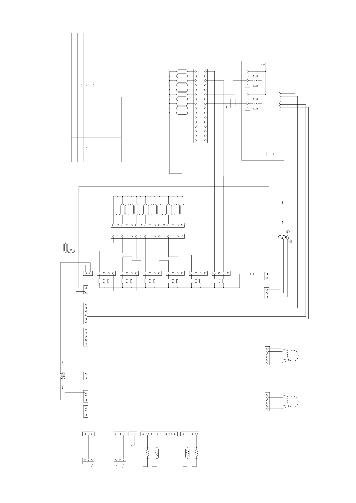
• CMB-P108V-E
–23–
Page 27
PE
3
2
1
3
2
1
EARTH
}
Power source
}}
L
N
Power source
/N 220V 240V 50Hz
Note:TB02 is terminal block for transmission.
Never connect power line to it.
Transmission line
Shield wire
SV10B
SV10A
SV10C
SV9B
SV9A
SV9C
BC Board
CN38
1
3
1
CNTR
CN50
CN51
7654321123456
CN02
CN12
153
31
7
5
3
1
7
5
3
1
7
5
3
1
7
5
3
1
7
5
3
1
7
5
3
1
3
TR
3
CNVCC1
12
X2
X1
X30
X4
X3
X31
X6
X5
X32
X8
X7
X33
X10
X9
X34
X12
X11
X35
X21
}
DC 30V
654321654321
LEV3 LEV1
1
2
3
CNP1
1
2
3
CNP3
2
1
1
2
3
4
5
6
7
8
4
3
2
1
123
21
CN03
CN13
CN10
CN11
CN07 CN05
CN36
TH11
TH12
TH15
TH16
PS1
PS3
20 22V
TB02
M2
M1
CN26
CN27
CN28
CN29
CN30
CN31
TB01
220 240V
LEV1
7654321123456
CN35
TB01
SV6B
SV6A
SV6C
SVM
16
15
14
13
12
11
10
9
8
7
6
5
4
3
2
1
16
15
14
13
12
11
10
9
8
7
6
5
4
3
2
1
RELAY4 Board
SV5C
SV5A
SV5B
SV4B
SV4A
SV4C
SV3B
SV3A
SV3C
SV2B
SV2A
SV2C
CN32
CN33
CN34
CN39
3
1
SV7C
SV7A
SV7B
SV8C
SV8A
SV8B
SV1C
SV1A
SV1B
X14
X13
X36
X37
X15
X16
98765432116 15 1011121314
12345678910111213141516
X18
X17
X38
X39
X19
X20
CN52CN53
5731753175317533 31
Symbol explanation
Terminal block
(for Transmission)
TB02
Terminal block
(for power source)
TB01
NameSymbol
Solenoid valve
Solenoid valve
Solenoid valve
Solenoid valve
Expansion valve
Thermister sensor
Transformer
NameSymbol
SV1 10A
SV1 10B
SV1 10C
SVM
TR
TH11 16
LEV1,3
PS1,3 Pressure sensor
• CMB-P1010V-E
–24–
Page 28

PE
EARTH
1
2
3
1
2
3
TB02
TB01
Name
Symbol
Terminal block
(for Transmission)
Solenoid valve
Solenoid valve
Solenoid valve
Solenoid valve
Terminal block
(for power source)
Pressure sensor
Expansion valve
Thermister sensor
Transformer
Name
SV1~13A
SV1~13B
SV1~13C
SVM
Symbol
TR
TH11~16
LEV1,3
PS1,3
M1
M2
DC 30V
}
Shield wire
Transmission line
Power source
}
L
N
Power source
~/N 220V~240V 50Hz
RELAY10
Board
BC Board
CN39
13
654321 1234567
CN51
CN50
135
CN12
13
CNOUT3
CNOUT1
1
3
5
7
1
3
5
7
1
3
5
7
1
3
5
7
1
3
5
7
1
3
5
7
1
3
5
7
1
3
5
7
7
5
3
1
1571571357
13
21
CNVCC2
3
CN42
X46
X47
X48
1
2
3
8
7
6
5
4
3
2
1
4
CNOUT2
CNOUT4
CN41
CN40
X41
X44
X40
X43
X42
X45
X20
X18
X19
X17
X39
X38
3
CNVCC1
12
X16
X15
X37
X36
X13
X14
X2
X1
X30
X4
X3
X31
X6
X5
X32
X8
X7
X33
X10
X9
X34
X12
X11
X35
X21
6
5432
1
6
5432
1
LEV3 LEV1
1
2
3
CNP1
1
2
3
CNP3
2
1
1
2
3
4
5
6
7
8
4
3
2
1
12321
CN03
CN02
CN13
CN10
CN11
CN07 CN05
33
CN34
CN33
1357
CN32
TH11
TH12
TH15
TH16
TR
TB02
CN38
CN26
CN27
CN28
CN29
CN30
CN31
TB01
CN35
3
1
CNTR
4
1
2
3
4
5
6
7
8
3
2
1
SV1B
SV1A
SV1C
SV2C
SV2A
SV2B
SV3C
SV3A
SV3B
SV4C
SV4A
SV4B
SV5B
SV5A
SV5C
1
2
3
4
5
6
7
8
9
10
11
12
13
14
15
16
1
2
3
4
5
6
7
8
9
10
11
12
13
14
15
16
SV9C
SV9A
SV9B
SV10C
SV10A
SV10B
16 15 14 13 12 11 10 9 8 7 6 5 4 3 2 1
14 13 12 11 101516 123456789
SV8B
SV8A
SV8C
SV7B
SV7A
SV7C
SVM
SV6C
SV6A
SV6B
SV11C
SV11A
SV11B
16
15
14
13
12
11
10
9
8
7
6
5
4
3
2
1
9
8
7
6
5
4
3
2
1
16
15
14
13
12
11
10
SV12C
SV12A
SV12B
SV13C
SV13A
SV13B
PS1
PS3
Note : 1. TB02 is transmission terminal block.
Never connect power line to it.
2. The initial set values of switch on CONT.B are
as follows : SW1 : 0, SW2:0.
20 22V 220 240V
CN36
• CMB-P1013V-E
–25–
Page 29
PE
EARTH
1
2
3
1
2
3
TB02
TB01
Name
Symbol
Terminal block
(for Transmission)
Solenoid valve
Solenoid valve
Solenoid valve
Solenoid valve
Terminal block
(for power source)
Pressure sensor
Expansion valve
Thermister sensor
Transformer
Name
SV1~16A
SV1~16B
SV1~16C
SVM
Symbol
TR
TH11~16
LEV1,3
PS1,3
M1
M2
DC 30V
}
Shield wire
Transmission line
Power source
}
L
N
Power source
~/N 220V~240V 50Hz
CN39
13
654321 1234567
CN51
CN50
135
CN12
13
CNOUT3
CNOUT1
1
3
5
7
1
3
5
7
1
3
5
7
1
3
5
7
1
3
5
7
1
3
5
7
1
3
5
7
1
3
5
7
7
5
3
1
1571571357
13
21
CNVCC2
3
CN42
X46
X47
X48
1
2
3
8
7
6
5
4
3
2
1
4
CNOUT2
CNOUT4
CN41
CN40
X41
X44
X40
X43
X42
X45
X20
X18
X19
X17
X39
X38
3
CNVCC1
12
X16
X15
X37
X36
X13
X14
X2
X1
X30
X4
X3
X31
X6
X5
X32
X8
X7
X33
X10
X9
X34
X12
X11
X35
X21
6
5432
1
6
5432
1
LEV3 LEV1
1
2
3
CNP1
1
2
3
CNP3
2
1
1
2
3
4
5
6
7
8
4
3
2
1
12321
CN03
CN02
CN13
CN10
CN11
CN07 CN05
33
CN34
CN33
1357
CN32
TH11
TH12
TH15
TH16
TR
TB02
CN38
CN26
CN27
CN28
CN29
CN30
CN31
TB01
CN35
3
1
CNTR
4
1
2
3
4
5
6
7
8
3
2
1
SV1B
SV1A
SV1C
SV2C
SV2A
SV2B
SV3C
SV3A
SV3B
SV4C
SV4A
SV4B
SV5B
SV5A
SV5C
1
2
3
4
5
6
7
8
9
10
11
12
13
14
15
16
1
2
3
4
5
6
7
8
9
10
11
12
13
14
15
16
SV9C
SV9A
SV9B
SV10C
SV10A
SV10B
16 15 14 13 12 11 10 9 8 7 6 5 4 3 2 1
14 13 12 11 101516 123456789
SV8B
SV8A
SV8C
SV7B
SV7A
SV7C
SVM
SV6C
SV6A
SV6B
SV11C
SV11A
SV11B
16
15
14
13
12
11
10
9
8
7
6
5
4
3
2
1
9
8
7
6
5
4
3
2
1
16
15
14
13
12
11
10
SV12C
SV12A
SV12B
SV13C
SV13A
SV13B
PS1
PS3
Note : 1. TB02 is transmission terminal block.
Never connect power line to it.
2. The initial set values of switch on CONT.B are
as follows : SW1 : 0, SW2:0.
1
2
2
1
1
3
5
7
1
3
5
7
1
3
5
7
X57
X53
X52
X56
X55
CN45
CN44
CN43
X50
SV14C
SV14A
SV14B
SV15A
SV15B
SV16C
SV16A
SV16B
SV15C
X54
X51
X49
RELAY10
Board
BC Board
20 22V 220 240V
CN36
• CMB-P1016V-E
–26–
Page 30
[5] Standard Operation Data
1 Cooling operation
Items
Power source
Ambient temp.
Indoor
Circulated water temp. (Intet)
Quantity
Indoor unit
Quantity in operation
Model
Main pipe
Condition
Piping
Branch pipe
Total piping length
Indoor unit fan notch
Refrigerant volume
Compressor volts / Frequency
Heat source unit
Heat source unit
V/Hz
DB/WB
°C
Q’ty
–
m
–
kg
V
V/Hz
A
PQRY-P200YMF-B PQRY-P250YMF-B
380-415V/50Hz 380-415V/50Hz
27.0/19.5 27.0/19.5
30 30
44
44
63 63 50 25 125 40 63 25
55
55555555
25 25
Hi Hi Hi Hi Hi Hi Hi Hi
11.4 12.2
380 415 380 415
270/77 270/77 340/98 340/98
14.0 12.8 18.8 17.2
Indoor unit
BC controller (1, 3)
Oil return
LEV opening
High pressure/Low pressure
BC controller liquid/Intermediate
Pressure
Discharge (TH1)
Accumulator
Heat
Suction (Comp)
source
unit
CS circuit (TH2)
Liquid level
Sectional temperature
Shell bottom (Comp)
Indoor
unit
LEV inlet
Heat exchanger outlet
Inlet
Outlet
Upper (TH4)
Lower (TH3)
Pulse
kg/cm
(MPa)
˚C
330 460 430 300 410 330 460 300
2000 240 2000 260
180 330
22.0/5.3 21.5/5.0
2
G
(2.20/0.52) (2.15/0.50)
20.9/20.9 20.4/20.4
(2.09/2.09) (2.04/2.04)
101 99.0
77
10 10
12 12
4.9 4.3
30 30
23.5 23.5
70 78
26 30
15 15
αOC
0.23 0.23
–27–
Page 31

2 Heating operation
Items
Power source
Ambient temp.
C
Circulated water temp.
Indoor
Quantity
Indoor unit
Quantity in operation
Model
Main pipe
Condition
Piping
Branch pipe
Total piping length
Indoor unit fan notch
Refrigerant volume
Compressor volts/Frequency
Heat source unit total current
Heat source unit
V/Hz
DB/WB
°C
Q’ty
–
m
–
kg
V
V/Hz
A
PQRY-P200YMF-B PQRY-P250YMF-B
380-415V/50Hz 380-415V/50Hz
21.0/– 21.0/–
20 20
44
44
63 63 50 25 125 40 63 25
55
55555555
25 25
Hi Hi Hi Hi Hi Hi Hi Hi
11.4 12.2
380 415 380 415
250/69 250/69 330/88 330/88
13.1 12.0 16.1 14.8
Indoor unit
BC controller (1, 3)
Oil return
LEV opening
High pressure/Low pressure
BC controller liquid/Intermediate
Pressure
Discharge (TH1)
Accumulator
Heat
Suction (Comp)
source
unit
CS circuit
Liquid level
Sectional temperature
Shell bottom (Comp)
Indoor
unit
LEV inlet
Heat exchanger outlet
Inlet
Outlet
(TH2)
Upper (TH4)
Lower (TH3)
Pulse
kg/cm
(MPa)
˚C
600 950 750 400 750 600 950 400
60 600 60 850
115 115
22.0/5.6 22.0/5.4
2
G
(2.20/0.56) (2.20/0.54)
21.0/18.0 21.0/18.0
(2.10/1.80) (2.10/1.80)
75 79
–1 –1
–4 –2
–1 –1
75
28 29
59
55 60
38 40
80 85
αOC
0.28 0.28
–28–
Page 32

[6] Function of Dip SW and Rotary SW
(1) Heat source unit
Switch Function
1~2
SWU
SW1
SW2
SW3
SW4
Unit address setting
1~8
For self diagnosis/
operation monitoring
9~10
1
Centralized control switch
2
Deletion of connection
information.
3
Deletion of error history.
4
Adjustment of refrigerant
Vol ume
5
6
7
Operation ON signal
output switching
Relay contact output
TB8-1,2
8
Disregard pump interlock
trouble.
9
10
SW3-2 Function valid/
1
invalid
Indoor unit test operation
2
CN51-3,5 Output switching
3
Freeze prevention operation
4
Target Te (α) at cooling-
5
only
Pump down operation
6
Target Tc (High pressure)
7
at heating
8
9
10
1
SW4-2 function valid/
Invalid
2
Configuration compensa-
tion value
3
Models
Function according to switch operation Switch set timing
When off When on When off When on
Set on 51~100 with the dial switch.
LED monitering display
–
Centralized control not
connected.
Storing of refrigeration
system connection
information.
Ordinary control
–
–
The relay closes during
compressor operation.
Normal
–
–
SW3-2 Function invalid
Stop all indoor units.
Water heat exchanger
freeze prevention signal
Normal
–
–
Changes as shown below by on → off change
0% → 3% → 6% → 9% → 12% → –6% → –3% → 0%
–
–
–
–
–
–
–
–2˚C
Invalid
50˚C
–
–
Model P200
Invalid
–
Centralized control
connected.
Deletion of refrigeration
system connection
information.
Deletion
Refrigerant volume
adjustment operation.
The relay closes during
reception of the cooling or
the heating operation
signal from the controller.
(Note: It is output even if
the thermostat is OFF
(when the compressor is
stopped).)
Disregard trouble
SW3-2 Function valid
All indoor units test
operation ON.
Heat source unit abnormal
output
Freeze prevention operation*
–
–
–
–
–
–5˚C
Valid
53˚C
–
–
Model P250
Valid
–
Before power is turned on.
During normal operation when power
is on.
Should be set on OFF.
Before power is turned on.
Before power is turned on.
During normal operation when power
is on.
During normal
operation when
power is on.
At all times
At all times
During normal operation when power
is on.
When SW3-1 is ON after power is
turned on.
At all times
At all times
At all times
During Comp stop (only when power
changes from OFF → ON)
During normal operation when power
is on.
When switching on the power.
During normal operation when power
is on.
When SW4-1 in ON.
Invalid 2 hours
after compressor
starts.
–
–
–
–
–
–
–
Note:
• SWU1~2=00 when shipped from the factory. Other factory settings are indicated by shaded portions.
• If the address is set from 01 to 50, it automatically becomes 100.
* Freeze prevention operation
When the water temp. (TH6) below less 5˚C during compressor is stopping, the compressor starts to run with cooling mode to
prevent the water freeze.
–29–
Page 33

(2) Indoor unit
DIP SW1, 3
Switch SW name
1
Room temp. sensor position
2
Clogged filter detect.
3
Filter duration
4
OA intake
5
Remote display select.
SW1
Humidifier control
6
Heating thermo. OFF airflow
7
Heating thermo. OFF airflow
8
Power failure automatic
9
return
10
Power source start/stop
1
Model selection
Cooling capacity saving
for PKFY-P. VAM,
Louver
effective/ineffective
Vane
Vane swing function
Vane horizontal angle
Vane angle set for cooling
SW3
2
3
4
5
6
7
Heating 4deg up
8
Operation by SW
OFF ON OFF ON
Indoor unit inlet
None
100h
Ineffective
Fan output display
At stationary heating
Very low speed
SW1-7 setting
Ineffective
Ineffective
Heat pump
None
None
None
1st setting
Down blow B, C
–
–
Effective
Built in remote controller
Provided
2500h
Effective
Thermo. ON signal display
Always at heat
Low speed
Set airflow
Effective
Effective
Cool.only
Provided
Provided
Provided
2nd setting
Horizontal
–
Ineffective
Switch set timing
At unit stopping
(at remote
controller OFF)
Remarks
Always ineffective for PKFY-P.VAM
Not provided for PKFY-P.VAM
Provided for PLFY-P.VGM (ON) setting
Always down blow B,C for PKFY-P.VAM
Horizontal (ON) setting for PLFY-P.VLMD
Ineffective (ON) setting for floor
standing
Note 1: The shaded part indicates the setting at factory shipment. (For the SW not being shaded, refer to the
table below.)
Switch
SW1
SW3
Model
3
6
7
3
4
6
8
VBM VLMD VKM VML VMH VM VLRM, VLEM VGM VAM VGM
OFF ON OFF ON ON OFF ON OFF
OFF ON OFF
OFF ON OFF
PLFY-P PEFY-P PDFY-P PFFY-P PCFY-P PKFY-P
OFF ON OFF
ON OFF ON
ON OFF ON OFF ON OFF ON
OFF ON OFF
Note 2: The Dip SW setting is only effective during unit stopping (remote controller OFF) for SW1, 2, 3 and 4 commonly
and the power source is not required to reset.)
3: When both SW1-7 and SW1-8 are being set to ON, the fan stops at the heating thermostat of OFF.
Setting of DIP SW2
Model P20 P25 P32 P40 P50 P63
Capacity (model name) code
SW2 setting
45 681013
OFF
ON
OFF
ON
OFF
ON
OFF
ON
OFF
ON
OFF
ON
Model P71 P80 P100 P125 P140
Capacity (model name) code
SW2 setting
14 16 20 25 28
ON
OFF
OFF
ON
OFF
ON
ON
OFF
OFF
ON
–30–
Page 34

Setting of DIP SW4 Setting of DIP SW5
Model Circuit board used
PMFY-P-DBM
PLFY-P-VLMD
PDFY-P20 ~ 80VM
PLFY-P40 ~ 63VKM
PLFY-P80 ~ 125VKM
PCFY-P-VGM
PKFY-P-VGM
PKFY-P-VAM
PFFY-P-VLEM, P-VLRM
PEFY-P20 ~ 32VML
PEFY-P40 ~ 140VMH
PDFY-P100·125VM
Phase control
Relay selection
1234
ON OFF ON OFF
––––
ON OFF ON OFF
OFF OFF OFF ON
ON OFF OFF ON
OFF ON OFF ON
OFF OFF ON ON
––––
OFF OFF OFF –
ON ON ON –
OFF OFF OFF –
OFF OFF ON –
SW4
220V
240V
Switch Function Operation by switch Switch set timing
(PLFY-P-VKM) (PCFY-P-VGM) (PDFY-P-VM)
SWA
SWA
1~3
Ceiling height setting
1~3
For options
* The ceiling
3
2
1
height is
changed by
SWB setting.
(PLFY-P-VLMD)
3
* As this switch is used by interlocking with SWC,
2
1
refer to the item of SWC for detail.
3
2
1
Ceiling height
33.5m
22.8m
12.3m
3
2
1
Always after powering
Always after powering
SWB
SWC
1~3
Setting of air outlet opening
1~2
Airflow control
(PLFY-P-VKM)
2-way
3-way
4-way
SWB
SWA
2-way 3.5m 3.8m 3.8m
3-way 3.0m 3.3m 3.5m
4-way 2.7m 3.0m 3.5m
(PLFY-P-VKM, PCFY-P-VGM, PKFY-P-VGM)
Option
Standard
* Set to the option to install the high efficiency
filter
(PLFY-P-VLMD)
3
2
1
SWA
Option
Standard
SWC
(PDFY-P-VM)
3
2
1
SWA
Option
Standard
SWC
123
Always after powering
Always after powering
(3) BC controller unit
DIP SW4
Switch Function
1 Models V-E type V-D type
SW4
2~8 –– –
Function according to switch operation
When off When on
*If the EPROM for the BC controller is WF30334, the controller is exclusively V-D type.
–31–
Page 35

[7] External Input/Output Specifications
(1) Output
1 Operation ON signal
Terminal No. TB8-1, 2
Output Relay contacts output Rated voltage: L1 - N: 220 ~ 240 V
Rated load: 1 A
Operation
2 COMP ON/OFF signal
Connector No. CN51-3, 4 Connector : B5B-XH-A (JST)
Output DC 12 V
Operation DC 12 V is output during compressor operation.
3 Water freeze / trouble signal
Connector No. CN51-3, 5 Connector : B5B-XH-A (JST)
Output DC 12 V
Operation
•
When DIP switch 2-7 is OFF
The relay closes during compressor operation.
•
When DIP switch 2-7 is ON
The relay closes during reception of the cooling or the heating operation signal from the controller.
(Note: It is output even if the thermostat is OFF (when the compressor is stopped).)
•
When DIP switch 3-3 is OFF
If the water temperature (TH 6) drops below 5°C while the unit is stopped, DC 12 V is output.
•
When DIP switch 3-3 is ON
DC 12 V is output when the heat source unit is stopped abnormally.
(2) Input
1 Pump Interlock
Terminal No. TB8-3, 4
Input Level signal
Operation If the circuit between TB8-3 and TB8-4 is open, compressor operation is prohibited.
2 Demand
Connector No. CN3D-1, 3 Connector : B3B-EH (JST)
Input Level signal
Operation If the circuit between CN3D-1 and CN3D-3 is opened, compressor operation is prohibited.
–32–
Page 36

33
3 TEST RUN
33
[1] Before Test Run
(1) Check points before test run
Neither refrigerant leak nor loose power source/ transmission lines should be found.
1
Confirm that the resistance between the power source terminal block and the ground exceeds 2MΩ by measuring it with a DC500V megger. Do not run if it is lower than 2MΩ.
2
Note) Never apply the megger to the MAIN board. If applied, the MAIN board will be broken.
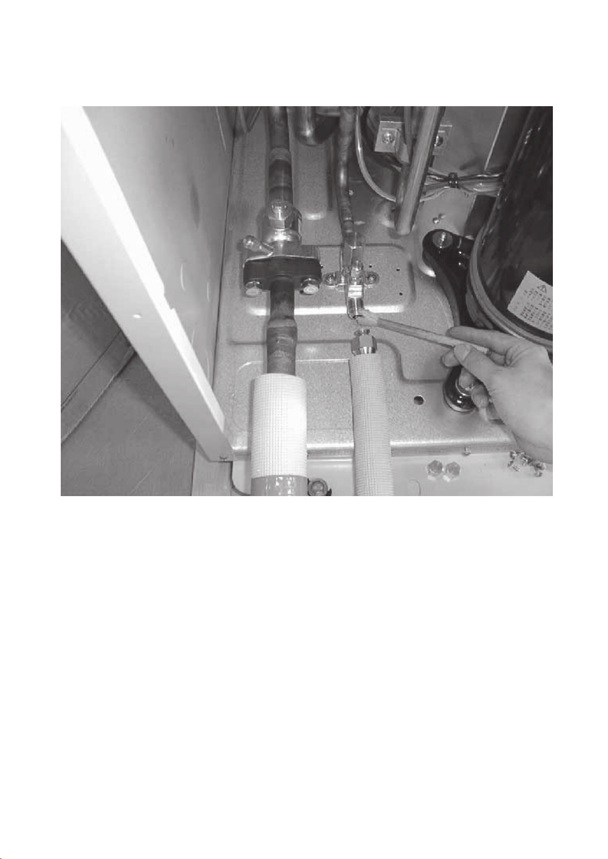
Confirm that the Ball valve at both gas and liquid sides is being fully opened.
3
Note) Certainly close the cap.
Be sure that the crankcase heater has been powered by turning the main power source on at least 12 hours
4
before starting the test run. The shorter powering time causes compressor trouble.
(2) Caution at inverter check
Because the inverter power portion in heat source unit electrical part box have a lot of high voltage portion, be sure to
follow the instructions shown below.
During energizing power source, never touch inverter power portion because high voltage (approx. 580V) is
1
applied to inverter power portion.
When checking,
1
Shut off main power source, and check it with tester, etc.
2
Allow 10 minutes after shutting off main power source.
2
Open the MAIN board mounting panel, and check whether voltage of both ends of electrolytic capacitor is
3
20V or less.
–33–
Page 37

(3) Check points for test run when mounting options
Built-in optional parts
Mounting of drain
water lifting-up
mechanism
1
2
3
Mounting of permeable film humidifier
(4) Attention for mounting drain water lifting-up mechanism
Work
Disassembling and
assembling of drain
water lifting-up
mechanism
Check humidifier operations and water
supply status in heating (test run) mode.
1
2
Content of test run
Release connector of pump circuit,
check error detection by pouring
water into drain pan water inlet.
After that, connect connector of
circuit.
Check pump operations and drainage status in cooling (test run) mode.
Content of test run
Lead wire from control box not
damaged.
Rubber cap properly inserted to
drain water outlet of drain pan?
Check point
Local remote controller displays code
No. “2503”, and the mechanism stops.
No overflow from drain pan.
Drain water comes out by operations of
drain pump.
Sound of pump operations is heard, and
drain water comes out.
No water leak from connecting portions
of each water piping.
Water is supplied to water supply tank,
and float switch is operating.
Check point Result
Insulation pipe
Result
Mounting of float
switch
Electric wiring
Insulation pipe of gas and liquid
3
pipes dealt with as shown in the right
figure?
Drain pan and piping cover mounted
4
without gap?
Drain pan hooked on cut projection
5
of the mechanism?
Float switch installed without contacting
with drain pan?
1
No mistakes in wiring?
Connectors connected surely and
2
tightly?
No tension on lead wire when sliding
3
control box?
No gap
1
Float switch moves smoothly.
Float switch is mounted on
2
mounting board straightly without
deformation.
Float switch does not contact with
3
copper pipe.
Wiring procedure is exactly followed.
Connector portion is tightly hooked.
–34–
Page 38

–35–
Page 39

(5) Check points for system structure
ex. PQRY-P200YMF-B
Check points from installation work to test run.
Classification
Installation and
piping
Power source
wiring
Portion
1
2
3
4
5
6
7
8
1
2
3
Check item
Instruction for selecting combination of heat source
unit, and indoor unit followed? (Maximum number of
indoor units which can be connected, connecting model
name, and total capacity.)
Follow limitation of refrigerant piping length? For example, 70m or less (total length : 220m) at the farthest.
Connecting piping size of branch piping correct?
Refrigerant piping diameter correct?
Refrigerant leak generated at connection?
Insulation work for piping properly done?
Specified amount of refrigerant replenished?
Pitch and insulation work for drain piping properly done?
Specified switch capacity and wiring diameter of main
power source used?
Proper grounding work done on heat source unit?
The phases of the L line (L1, L2, L3) correct?
Trouble
Not operate.
Not cool (at cooling).
Not heat (at heating).
Not cool, not heat, error stop.
Condensation drip in piping.
Not cool, not heat, error stop.
Water leak, condensation drip in drain piping.
Error stop, not operate.
Electric shock.
Error stop, not operate.
4
L line and N line connected correct?
The some electric pars should be
damaged.
–36–
Page 40
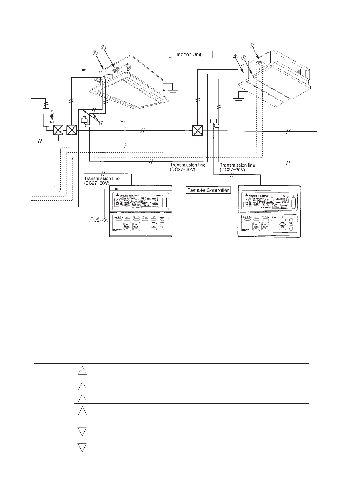
Classification
Portion Check item
Trouble
Transmission
line
System set
1
Limitation of transmission line length followed? For
example, 200m or less (total length : 500m) at the farthest.
2 1.25mm2 or more transmission line used?
(Remote controller 10m or less 0.75mm
2
)
3 2-core cable used for transmission line?
4 Transmission line apart from power source line by 5cm
or more?
5 One refrigerant system per transmission line?
The short circuit connector is changed form CN41 to CN40
6
on the MAIN board when the system is centralized control?
(Just one heat source unit. Not all heat source units.)
7 No connection trouble in transmission line?
Address setting properly done? (Remote controller,
1
indoor unit and heat source unit.)
Setting of address No. done when shutting off power
2
source?
Address numbers not duplicated?
3
Turned on SW3-8 on indoor unit circuit board when
4
mounting room thermistor sensor?
Erroneous operation, error stop.
Erroneous operation, error stop.
Error stop in case multiple-core
cable is used.
Erroneous operation, error stop.
Not operate.
Not operate.
Error stop or not operate.
Error stop or not operate.
Can not be properly set with power
source turned on.
Not operate.
Set temperature not obtained at
heating operations (Thermostat
stop is difficult)
Before starting
Refrigerant piping ball valve (Liquid pressure pipe, gas
1
pressure pipe) opened?
Turn on power source 12 hours before starting opera-
2
tions?
–37–
Error stop.
Error stop, compressor trouble.
Page 41

[2] Address setting
(1) Switch operation
In order to constitute CITY MULTI in a complete system, switch
operation for setting the unit address No. and connection No. is
required.
1 Unit address No. group No. and connection No.
The unit address No. is determined by the address setting
switch of the heat source unit, indoor unit and remote controller.
2 Caution for switch operations
1
Be sure to shut off power source before switch setting. If operated with power source on, switch can
not operate properly.
2
Address switch shall follow decimal system with 2 digits. Set 000 ~ 250
Heat source unit
Indoor unit
0
1
9
8
7
6
5
10 1
No units with identical unit address shall exist in one system. If set erroneously, system can not
3
0
1
9
2
3
4
2
8
3
7
4
6
5
operate.
Remotecontroller
0
1
9
2
8
3
7
4
6
5
10 1
Rotary switch
Connection
No. setting
0
1
2
F
E
D
C
B
7
8
A
9
Indoor unit
Heat source unit
0
1
9
2
8
3
7
4
6
5
BC controller
Remote controller (Main)
Pair remote controller (Sub)
MJ-103
Unit address No. setting
0
3
4
5
6
9
8
7
6
5
1
2
3
4
0
1
9
2
8
3
7
4
6
5
01~50
51~99,100
51~99,100
101~150
151~199, 200
000, 201~250
(2) Address setting and switch operations
1 In case of system with a single system
(In case higher rank controller such as remote controller for centralized control is not connected)
Unit
Indoor unit
Heat source unit
BC controller
Remote controller
(Main)
Remote controller
(Sub)
Remote controller
MJ-103
Fresh Master
Address setting
01~50
51~99, 100
51~99, 100
101~150
151~199, 200
000, 201~250
1~50
1
Fixed
1
Fixed
8
7
9
6
100
9
8
7
9
8
7
9
8
7
0
1
2
3
4
5
9
8
7
Example
0
1
2
8
3
7
4
6
5
10 1
0
1
2
8
3
7
4
6
5
10 1
0
1
2
8
3
7
4
6
5
10 1
0
1
9
2
8
3
7
4
6
5
10 1
0
1
9
2
8
3
7
4
6
5
10 1
0
1
9
2
8
3
7
4
6
5
10 1
0
1
2
8
3
7
4
6
5
10 1
0
1
9
2
3
4
6
5
0
1
9
4
6
5
0
1
9
4
6
5
8
8
The smallest address of indoor unit in same refrigerant
2
system + 50
3
*If the address is to be 100, use “50.”
The address of Heat source unit + 1
2
3
*If the address is to be 100, use “50.”
0
1
The smallest address of indoor unit in the group + 100
9
2
3
*The place of "100" is fixed to "1"
7
4
6
5
The address of main remote controller + 50
0
1
9
2
*The address automatically becomes "200" if it is set as
3
7
4
6
5
"00"
0
1
9
2
8
3
7
4
6
5
· The Fresh Master system allows you to select operations using the remote controller or using the indoor
0
1
9
2
3
4
6
5
unit. Use the dip switch (SW3-1) to make this selection.
See the section “Fresh Master operation/Remote
controller switching” for settings.
· For operations using the remote controller, use the
same setting method as for the indoor unit.
· For operations using the indoor unit, settings should be
within the range 01 – 50, without respect to the group.
Note
Lossnay unit
1~50
0
1
9
2
8
3
7
4
6
5
10 1
0
9
8
7
6
–38–
1
4
5
Set within the range 01 – 50 with no duplications.
2
3
Page 42

2 Branch number switch (Indoor Units and Fresh Master)
Match the indoor unit’s refrigerant pipe with the BC controller’s end connection number.
When combining branches, choose the smallest connection number in the series.
The indoor unit capacity limit for connecting to a branch is 80. Max. 3sets for 1 connection.
When selecting connection number 16, choose 0 as the setting for the branch number switch.
Connecting one unit to one branch
Combining branches
BC controller
1 2 3 4 5 6
1
3 4 5 6
Above 80
1 2 3 4 5 6
BC controller
1 2 3 4 5 6
Connecting more than one unit to one branch
BC controller
1 2 3 4 5 6
1 1 2 3 4 5 6
Below 80
3 In the case of group operations of indoor units of different refrigerant system
(Including the case of connecting with higher rank controller such as remote controller for centralized controller).
Group setting shall be done with remote controller. ( When the centralized remote controller is connected, the
setting should be done with the centralized remote controller.) Address setting can be done on each unit freely.
Regarding transmission wiring, provide 2-wire jumper system (Centralized system transmission line) to outdoor
units to be connected to indoor unit in the same group, and mount short circuit connector on CN41 to CN40 for
replacement for one of the outdoor units. (However, when the higher rank controller like that for centralized
controller is connected, do not replace the short circuit connector to CN40.)
–39–
Page 43

(3) Examples of switch settings
System diagram Description
1 Individual operation
Heat
source
unit
51
52
BC
controller
TB3
2 Group operation
Heat
source
unit
TB3
52
51
BC
controller
Indoor unit
01
101
Remote
controller
Indoor unit Indoor unit Indoor unit
01 02 03
Remote
controller
Indoor unit Indoor unit
02
102
Remote
controller
103101
Remote
controller
(Main)
03
103
Remote
controller
153
Remote
controller
(Sub)
[Switch settings]
(1) Address switch
Unit
Indoor unit
Remote controller
Heat source unit
BC controller
Range
01~50
101~150
Note 1
51~100
Note 2
51~100
Note 2
Indoor unit setting + 100
Smallest address among
indoor units + 50
Heat source unit + 1
Note 1. For remote controllers, it is not necessary to set
digits in the hundreds column.
Note 2. When setting heat source unit address or BC
controller address to 100, set the address
setting switch to 50.
Setting
–
(2) Branch number switch
Match the indoor unit’s refrigerant pipe with
the BC controller’s end connection number.
[Switch settings]
(1) Address switch
Unit
IC (Main)
IC (Sub)
Remote controller
(Main)
Remote controller
(Sub)
Heat source unit
BC controller
Range
01~50
01~50
101~150
Note 1
151~200
Note 1
51~100
Note 2
51~100
Note 2
Smallest address among
several indoor units that
form a single group.
Address other than the IC
(Main) among several
indoor units that form a
single group. Use
numerical order starting
after the IC (Main).
Address of IC (Main)
within the same group +
100
Address of IC (Main)
within the same group +
150
Smallest address among
indoor units + 50
Heat source unit + 1
Setting
–40–
Notes 1 and 2 : same as above.
(2) Branch number switch
Same as 1 Individual operation.
Page 44

System diagram Description
3 System for operating with Fresh Master (Lossnay)
Heat
source
unit
TB3
52
51
BC
controller
Indoor unit Indoor unit Indoor unit Fresh Master
01 02 03
[Switch settings]
This is the same as 1 Individual operation.
However, keep the Fresh Master address within the 1
~50 range to avoid duplication with other indoor units.
[Registering with a remote controller]
04
Registers operation of Fresh Master and indoor units
using the remote controller.
101 102 103
Remote
controller
System for operating multiple-refrigerant + Fresh Master (Lossnay)
4
Change
CN40CN41
Heat
source
unit
51
TB7
TB3
BC
controller
Indoor unit
01
52
Remote
controller
Remote
controller
Indoor unit Indoor unit Indoor unit
02 03 04
Remote
controller
In series with ventilation
103101
Remote
controller
Indoor unit
01, 02, 03
← →
Fresh Master
04
[Switch settings]
Same as 1 Individual operation.
*Remote controllers for groups
using different refrigerants connect
to transfer line of the latest indoor
unit in the group.
[Managing electrical supply connector CN40]
Changes the single electrical supply connector of an
outdoor unit group from CN41 to CN40.
[Registration using a remote controller]
1 Group setting
After power is turned on, this changes indoor units
and network remote controllers to group setting.
Heat
source
unit
TB3
55
TB7
56
BC
controller
08
Fresh
Master
Indoor unit Indoor unit Indoor unit
07 06 05
107
Remote
controller
In series with ventilation
Remote controller
101
103
← →
← →
Indoor unit
01, 02
03, 04
05, 06
107
2 Operation registration
After power is turned on, this activates operation
registration for Fresh Master and indoor units
using remote controllers.
Indoor unit
← →
07
Fresh Master
01, 02, 03
04, 05, 06
← →
08
07
–41–
Page 45

System diagram Description
5 PAC-SC30GR connection
Change
Where a group remote controller is
connected to a transfer line for indoor units.
CN40CN41
Indoor unit
Indoor unit Indoor unit Indoor unit
104 105
Remote
controller
Heat
source
unit
Heat source
unit
Electrical
supply
device
51
TB7
TB3
52
BC
controller
54
TB7
TB3
56
BC
controller
GR
201
GR
201
Connect to one or the other
Indoor unit Indoor unit
01 02 03
101 103
Remote
controller
0504 06
Remote
controller
In series with ventilation
Remote
controller
[Switch settings]
Address switch settings are the same as 1 Individual
operation.
This turns on the central manager switch (SW2-1) of
the outdoor unit.
*Remote controllers for groups
using different refrigerants connect
to transfer line of the latest indoor
unit in the group.
[Managing electrical supply connector CN40]
When a group remote controller (GR) is connected to
a transfer line for indoor units, this changes the single
electrical supply connector in an outdoor unit group
from CN41 to CN 40.
When connected to a transfer line for central managers, leave it as is (on CN41).
(receiving electrical power from an electrical supply
device)
[Registration using a group remote controller]
1 After power is turned on, this changes indoor units
to group setting with a group remote controller
2 This sets the relations between indoor units and
remote controllers using a group remote controller.
Indoor unit
101
103
104
107
← →
← →
← →
Group remote controllers can be
connected to both indoor/outdoor
unit transfer lines and central
manager transfer lines.
Remote controller
01, 02
03
04
05, 06
6 MJ-103 MTR connection
Heat
source
unit
51
TB7
TB3
Heat
source
unit
55
TB7
TB3
MJ-103MTR
BC
controller
BC
controller
Indoor unit Indoor unit
52
Fresh
Master
56
000
Electrical
supply
device
01 02 03 04
08 07 06 05
101 103
Remote
controller
Indoor unit
107
Remote
controller
In series with ventilation
Indoor unit Indoor unit
Remote
controller
Indoor unit Indoor unit
[Switch settings]
Address switch settings are the same as 1 Individual
operation
This turns on the central manager switch (SW2-1) of
the outdoor unit.
[Registration using a central controller]
1 Group setting
· After turning on the power, this activates group
setting for indoor units using a central controller.
· This activates settings for indoor units and
remote controllers using a central controller.
Remote controller
101
103
← →
← →
Indoor unit
01, 02
03, 04
05, 06
107
← →
2 Settings for Lossnay and indoor units are made
using a central controller.
Indoor unit
01~07
Fresh Master
← →
07
08
–42–
Page 46

[3] Test Run Method
Operation procedure
Turn on universal power supply at least 12 hours before getting started → Displaying “HO” on display panel for
1
about two minutes
2 Press
3 Press
4
5 Press
6 Press
7 Make sure that indoor unit fans operate normally
8 Make sure that interlocking devices such as ventilator operate normally if any
9 Press
Note 1: If check code is displayed on remote controller or remote controller does not operate normally.
TEST RUN
Press
warm or cold air is blowing out
or button to change wind → Make sure that horizontal or downward blow is adjustable.
ON/OFF
2: Test run automatically stops operating after two hours by activation of timer set to two hours.
3: During test run, test run remaining time is displayed on time display section.
4: During test run, temperature of liquid pipe in indoor unit is displayed on remote controller room temperature
display section.
5: When pressing
controller. However, it is not a malfunction.
6: When pressing
remote controller. However, it is not a malfunction.
button twice → Displaying “TEST RUN’’ on display panel
selection button → Make sure that air is blowing out
select button to change from cooling to heating operation, and vice versa → Make sure that
adjust button → Make sure that air blow is changed
button to cancel test run → Stop operation
adjust button, depending on the model, “NOT AVAILABLE” may be displayed on remote
or button, depending on the model, “NOT AVAILABLE” may be displayed on
–43–
Page 47

44
4 GROUPING REGISTRATION OF INDOOR UNITS WITH REMOTE CONTROLLER
44
(1) Switch function
• The switch operation to register with the remote controller is shown below:
–
ON/OFF
CENTRALLY CONTROLLED
CHECK
STAND BY
DEFROST
INDOOR UNIT
ADDRESS NO.
ON OFF
CLOCK
˚C
ERROR CODE
OA UNIT ADDRESS NO.
1Hr.
NOT AVAILABLE
˚C
FILTER
CHECK MODE
TEST RUN
F Delete switch
ON OFFCLOCK
G Registered mode
selector switch
E Confirmation switch
NETWORK
REMOTE CONTROLLER
PAR-F25MA
Name Name of actual switch Description
Registration/ordinary
mode selection switch
Symbol
of switch
A + B
FILTER
TEMP. TIMER SET
C Switch to assign
indoor unit address
+
H Switch to assign inter-
locked unit address
This switch selects the ordinary mode or registered mode (ordinary
mode represents that to operate indoor units).
* To select the registered mode, press the
switch continuously for over 2 seconds under stopping state.
[Note] The registered mode can not be obtained for a while after
powering.
Pressing the
FILTER
+ switch displays “CENTRALLY
CONTROLLED”.
Switch to assign indoor
unit address
C
of TEMP
This switch assigns the unit address for “INDOOR UNIT ADDRESS
NO.”
FILTER
CHECK
TEST RUN
A
B
D Registration switch
FILTER
+
Registration/
ordinary mode
selector switch
Registration switch
Confirmation switch
Delete switch
Registered mode
selector switch
Switch to assign
interlocked unit address
D
TEST RUN
E
This switch is used for group/interlocked registration.
This switch is used to retrieve/identify the content of group and interlocked (connection information) registered.
F
CLOCK
ON OFF
This switch is used to retrieve/identify the content of group and interlocked (connection information) registered.
G
This switch selects the case to register indoor units as group (group
setting mode) or that as interlocked (interlocked setting mode).
*The unit address is shown at one spot for the group setting mode
while at two spots for the interlocked setting mode.
H
of TIMER SET
This switch assigns the unit address of “OA UNIT ADDRESS NO.”
–44–
Page 48

(2) Attribute display of unit
• At the group registration and the confirmation/deletion of registration/connection information, the type (attribute) of the
unit is displayed with two English characters.
Display Type (Attribute) of unit/controller
Indoor unit connectable to remote controller
Heat source unit
Local remote controller
System controller (MJ)
[Description of registration/deletion/retrieval]
• The items of operation to be performed by the remote controller are given below. Please see the relating paragraph for
detail.
1 Group registration of indoor unit
• The group of the indoor units and operating remote controller is registered.
• It is usually used for the group operation of indoor units with different refrigerant system.
2 Retrieval/identification of group registration information of indoor units
• The address of the registered indoor units in group is retrieved (identified).
3 Retrieval/identification of registration information
• The connection information of any unit (indoor/heat source units, remote controller or the like) is retrieved (identified).
4 Deletion of group registration information of indoor units
• The registration of the indoor units under group registration is released (deleted).
5 Deletion of the address not existing
• This operation is to be conducted when “6607” error (No ACK error) is displayed on the remote controller caused by
the miss setting at test run, or due to the old memory remained at the alteration/modification of the group composition.
Caution:
When MELANS (MJ-103MTRA for example) is being connected, do not conduct the group/pair registration using
the remote controller. The group/pair registration should be conducted by MELANS. (For detail, refer to the instruction exclusively prepared for MELANS.)
–45–
Page 49

(3) Group registration of indoor unit
1) Registration method
• Group registration of indoor unit ........................................................................ 1
The indoor unit to be controlled by a remote controller is registered on the remote controller.
[Registration procedure]
1 With the remote controller under stopping or at the display of “HO”, continuously press the
FILTER
+ switch
(A + B) at the same time for 2 seconds to change to the registration mode. (See the figure below.)
2 Assign the indoor unit address to “INDOOR UNIT ADDRESS NO.” by operating the (Room temperature
adjustment) (C).
Then press the
TEST RUN
switch (D) to register. In the figure below, the “INDOOR UNIT ADDRESS NO.” is being set
to 001.
3 After completing the registration, press the
FILTER
+ switch (A + B) at the same time for 2 seconds to
change to the original ordinary mode (with the remote controller under stopping).
Ordinary mode
• Remote controller under stopping • “HO” under displaying
CENTRALLY CONTROLLED
STAND BY
DEFROST
NETWORK
REMOTE CONTROLLER
PAR-F25MA
˚C
INDOOR UNIT
ERROR CODE
ADDRESS NO
OA UNIT ADDRESS NO
1
Group setting mode
˚C
INDOOR UNIT
ERROR CODE
OA UNIT ADDRESS NO
ADDRESS NO
1Hr.
CHECK
INDOOR UNIT
ADDRESS NO.
ON OFF
CLOCK
˚C
ERROR CODE
OA UNIT ADDRESS NO.
ON OFFCLOCK
TEMP. TIMER SET
NOT AVAILABLE
˚C
FILTER
CHECK MODE
TEST RUN
ON/OFF
–
FILTER
CHECK
TEST RUN
1
2 + 3
˚C
INDOOR UNIT
ERROR CODE
ADDRESS NO
OA UNIT ADDRESS NO
• Registration complete
▲
Indicates the type of unit
(Indoor unit in this case)
INDOOR UNIT
ADDRESS NO
˚C
ERROR CODE
OA UNIT ADDRESS NO
• Registration error
▼
“88” flickers indicating registration error. (when the indoor unit
registered is not existing)
INDOOR UNIT
ADDRESS NO
˚C
ERROR CODE
OA UNIT ADDRESS NO
2 Assign the
address (C)
System example
Remote controller
1 Change to the
registration
mode (A + B)
3 Press the
registration
switch (D)
Indoor units
Group
• Confirm the indoor unit address No.
• Confirm the connection of the transmission line.
–46–
Page 50

2) Method of retrieval/confirmation
• Retrieval/confirmation of group registration information on indoor unit ............... 2
The address of the indoor unit being registered on the remote controller is displayed.
[Operation procedure]
1 With the remote controller under stopping or at the display of “HO”, continuously press the
FILTER
+ B) at the same time for 2 seconds to change to the registration mode.
2 In order to confirm the indoor unit address already registered, press
switch (E). (See figure below.) When the group
of plural sets is registered, the addresses will be displayed in order at each pressing of switch (E).
3 After completing the registration, continuously press the
FILTER
+ switch (A + B) at the same time for 2
seconds to change to the original ordinary mode (with the remote controller under stopping).
• Registered
+ switch (A
CENTRALLY CONTROLLED
STAND BY
DEFROST
NETWORK
REMOTE CONTROLLER
PAR-F25MA
CHECK
˚C
INDOOR UNIT
ADDRESS NO.
TEMP. TIMER SET
ON OFF
CLOCK
ERROR CODE
OA UNIT ADDRESS NO.
NOT AVAILABLE
ON OFFCLOCK
–
ON/OFF
1Hr.
˚C
FILTER
CHECK MODE
TEST RUN
FILTER
CHECK
TEST RUN
1
1
▲
Indicates the type of unit
(Indoor unit in this case)
• No registration.
▼
INDOOR UNIT
ADDRESS NO
INDOOR UNIT
ADDRESS NO
˚C
ERROR CODE
OA UNIT ADDRESS NO
˚C
ERROR CODE
OA UNIT ADDRESS NO
Note: Only one address will be displayed
1 Press the switch for confirmation (E)
when the registration is one even the
switch is how often pressed
• Retrieval/confirmation of registration information ................................................ 3
The registered information on a certain unit (indoor unit, heat source unit, remote controller or the like) is displayed.
[Operation procedure]
1 With the remote controller under stopping or at the display of “HO”, continuously press the
FILTER
+ B) at the same time for 2 seconds to change to the registration mode.
2 Operate switch (G) for the interlocked setting mode. (See figure below.)
3 Assign the unit address of which registration information is desired to confirm with the
(TIMER SET) switch
(H). Then press the switch (E) to display it on the remote controller. (See figure below.)
Each pressing of switch (E) changes the display of registered content. (See figure below.)
4 After completing the retrieval/confirmation, continuously press the
FILTER
+ switch (A + B) at the same time
for 2 seconds to change to the original ordinary mode (with the remote controller under stopping).
+ switch (A
–47–
Page 51

CENTRALLY CONTROLLED
STAND BY
DEFROST
NETWORK
REMOTE CONTROLLER
PAR-F25MA
CHECK
˚C
INDOOR UNIT
ADDRESS NO.
TEMP. TIMER SET
ON OFF
CLOCK
ERROR CODE
OA UNIT ADDRESS NO.
ON OFFCLOCK
1Hr.
NOT AVAILABLE
˚C
FILTER
CHECK MODE
TEST RUN
ON/OFF
TEST RUN
–
FILTER
CHECK
1 + 2
▲
• Registered
INDOOR UNIT
ADDRESS NO
INDOOR UNIT
ADDRESS NO
INDOOR UNIT
ADDRESS NO
˚C
ERROR CODE
OA UNIT ADDRESS NO
(Alternative
display)
˚C
ERROR CODE
OA UNIT ADDRESS NO
˚C
ERROR CODE
OA UNIT ADDRESS NO
(Alternative
display)
2
2 Press the switch for
confirmation (E)
1 Set the address
INDOOR UNIT
ADDRESS NO
INDOOR UNIT
ADDRESS NO
˚C
ERROR CODE
OA UNIT ADDRESS NO
˚C
ERROR CODE
OA UNIT ADDRESS NO
* Same display will appear when
• No registration
the unit of “007” is not existing.
▼
˚C
INDOOR UNIT
ERROR CODE
OA UNIT ADDRESS NO
3) Method of deletion
• Deletion of group registration information of indoor unit ...................................... 4
[Operation procedure]
1 With the remote controller under stopping or at the display of “HO”, continuously press the
switch (A + B) at the same time for 2 seconds to change to the registration mode.
2 Press the switch (E) to display the indoor unit address registered. (As same as 2)
3 In order to delete the registered indoor unit being displayed on the remote controller, press the
times continuously. At completion of the deletion, the attribute display section will be shown as “ – – “.
(See figure below.)
Note: Completing the deletion of all indoor units registered on the remote controller returns to “HO” display.
4 After completing the registration, continuously press the
FILTER
+ switch (A + B) at the same time for 2
seconds to change to the original ordinary mode (with the remote controller under stopping).
ADDRESS NO
FILTER
CLOCK ON OFF
+
(F) switch two
CENTRALLY CONTROLLED
STAND BY
DEFROST
NETWORK
REMOTE CONTROLLER
PAR-F25MA
CHECK
˚C
INDOOR UNIT
ADDRESS NO.
TEMP. TIMER SET
CLOCK
ERROR CODE
OA UNIT ADDRESS NO.
ON OFF
ON OFFCLOCK
1Hr.
NOT AVAILABLE
˚C
FILTER
CHECK MODE
TEST RUN
1 Press the switch for confirmation (F)
twice continuously.
ON/OFF
TEST RUN
–
FILTER
CHECK
1
In case group registration with other
indoor unit is existing
1
In case no group
registration with other
indoor unit is existing
–48–
• Deletion completed
▲
˚C
INDOOR UNIT
ERROR CODE
OA UNIT ADDRESS NO
ADDRESS NO
“– –” indicates the
deletion completed.
• Deletion completed
▼
˚C
INDOOR UNIT
ADDRESS NO
ERROR CODE
OA UNIT ADDRESS NO
ON/OFF
–
Page 52
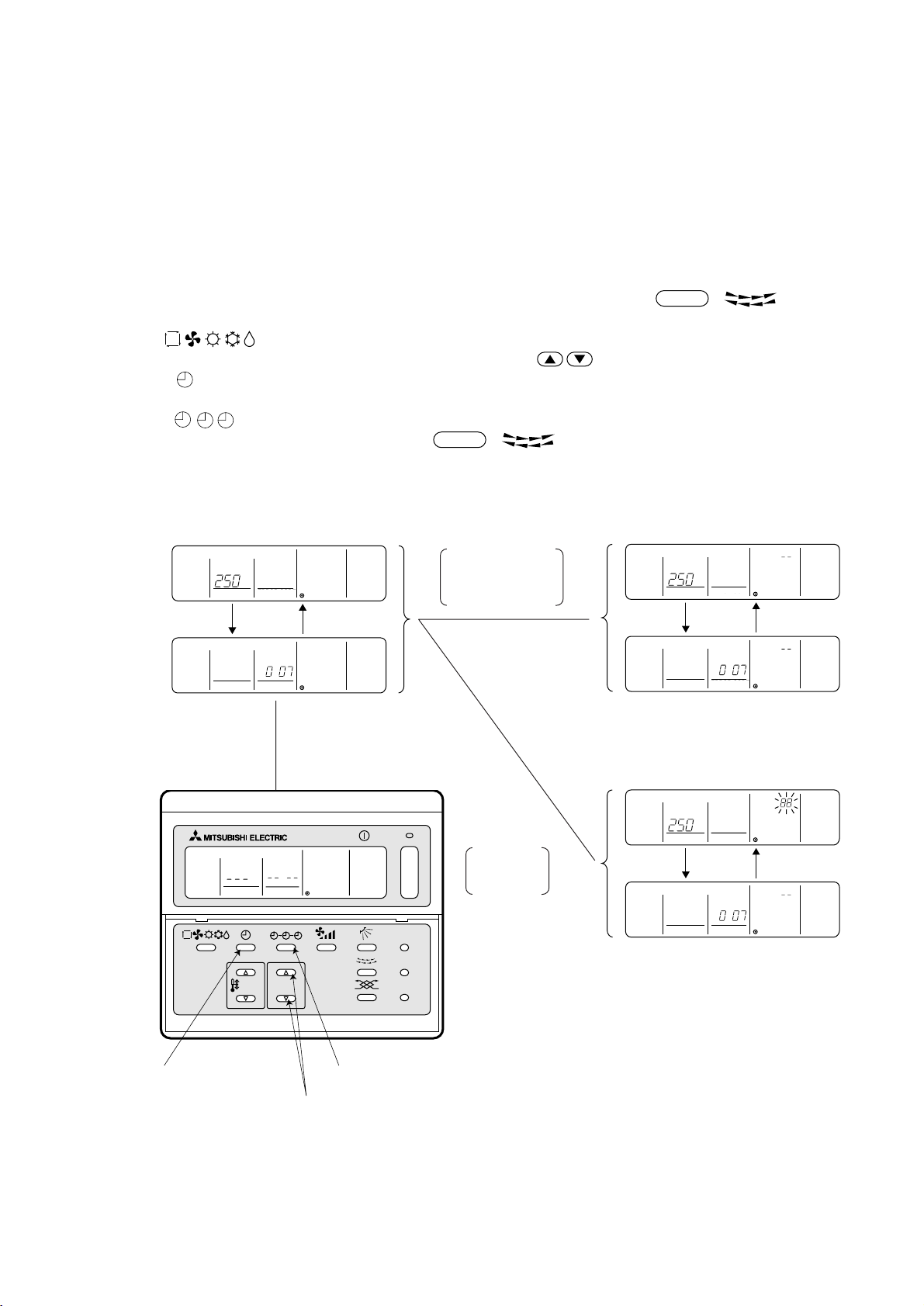
4) Deletion of information on address not existing
• Deletion of information on address not existing ................................................... 5
This operation is to be conducted when “6607” error (No ACK error) is displayed on the remote controller caused by
the miss setting at test run, or due to the old memory remained at the alteration/modification of group composition,
and the address not existing will be deleted.
Note: The connection information (connection between indoor unit and heat source unit) on the refrigerant system
can not be deleted.
An example to delete the system controller of “250” from the indoor unit of “007” is shown below.
[Operation procedure]
1 With the remote controller under stopping or at the display of “HO”, continuously press the
FILTER
+ switch (A
+ B) at the same time for 2 seconds to change to the registration mode.
2 Operate
switch (G) for the interlocked setting mode ( ii ). (See the figure below.)
3 Assign the unit address existing to “OA UNIT ADDRESS No.” with the (Room temperature control) switch (C),
and press switch (E) to call the address to be deleted. (See the figure below.) As the error display on the remote
controller is usually transmitted from the indoor unit, “OA UNIT ADDRESS No.” is used as the address of the indoor unit.
4 Press the
5 After completing the deletion, continuously press the
CLOCK
OFF
ON
switch (F) twice. (See the figure below.)
FILTER
+ switch (A + B) at the same time for 2 seconds
to return to the original ordinary mode (with the remote controller under stopping).
• Deletion completed
When both indoor
INDOOR UNIT
ADDRESS NO
˚C
ERROR CODE
OA UNIT ADDRESS NO
(Alternative
display)
unit and interlocked
unit addresses are
existing
3
▲
INDOOR UNIT
ADDRESS NO
(Alternative
˚C
ERROR CODE
OA UNIT ADDRESS NO
display)
INDOOR UNIT
ADDRESS NO
CENTRALLY CONTROLLED
CHECK
STAND BY
INDOOR UNIT
DEFROST
ADDRESS NO.
NETWORK
REMOTE CONTROLLER
PAR-F25MA
2 Press the switch for
confirmation (E)
˚C
ERROR CODE
OA UNIT ADDRESS NO
▲
1 + 2
1Hr.
ON OFF
CLOCK
˚C
ERROR CODE
OA UNIT ADDRESS NO.
TEMP. TIMER SET
1 Set the address (H)
NOT AVAILABLE
ON OFFCLOCK
3 Press the deletion switch (F) twice
˚C
FILTER
CHECK MODE
TEST RUN
ON/OFF
TEST RUN
–
FILTER
CHECK
3
Deletion of
address not
existing
˚C
INDOOR UNIT
ADDRESS NO
• Deletion completed
˚C
INDOOR UNIT
ADDRESS NO
▼
(Alternative
INDOOR UNIT
ADDRESS NO
˚C
ERROR CODE
OA UNIT ADDRESS NO
*
ERROR CODE
OA UNIT ADDRESS NO
display)
ERROR CODE
OA UNIT ADDRESS NO
*
–49–
Page 53

55
5 CONTROL
55
[1] Control of Heat Source Unit
(1) Initial processing
• When turning on power source, initial processing of microcomputer is given top priority.
• During initial processing, control processing corresponding to operation signal is suspended. The control processing is resumed after initial processing is completed. (Initial processing : Data processing in microcomputer and
initial setting of each LEV opening, requiring approx. 2 minutes at the maximum.)
(2) Control at staring
• In case unit is started within 2 hours after turning on power source at low ambient temperature (+5˚C or less), the
unit does not start operating for 30 minutes at the maximum.
(3) Bypass, capacity control
• Solenoid valve consists of bypass solenoid valve (SV1, SV2) bypassing between high pressure side and low
pressure sider. The following operation will be provided.
1) Bypass solenoid valves SV1 and SV2 (both “open” when turned on)
Item
When starting compressor
After thermost “ON is returned and
after 3 minutes restart
When compressor stops in cooling or
heating mode
After operation stops
During oil recovery operations
During 20Hz operations, at fall in low
pressure
When high pressure rises (Pd)
When high pressure (Pd) rises during
20Hz operations
(3 minutes after starting)
When discharge temperature rises
(3 minutes after starting)
Compressor
SV1
ON (Open) OFF (Close)
Turned on for 4 minutes
Turned on for 4 minutes
Always turned on
Turned on for 3 minutes
Always turned on.
–
When Pd reaches
27.5kg/cm2G
(2.70MPa)
When Pd is under
24kg/cm2G (2.35MPa)
and 30 seconds
–
SV2
ON (Open) OFF (Close)
–
–
–
–
Always turned on.
When Ps is 1.5kg/
cm2G (0.15MPa) or
less
When Pd reaches
26.5kg/cm2G
(2.60MPa)
Turned on when high
pressure (Pd) exceeds pressure limit
When temp. exceeds
130˚C
When Ps is 2.5kg/
cm2G (0.25MPa) or
more
When Pd is under
23.5kg/cm2G
(2.30MPa) and 30
seconds
When high pressure
(Pd) is 20kg/cm2G
(1.96MPa) or less
When discharge
temp. is 115˚C
Bypass
solenoid
valve (SV1)
Start
(4-minute)
Thermo.
OFF
Thermo.
ON
(2-minute) (3-minute)
Stop
(4) Frequency control
• Depending on capacity required, capacity control change and frequency change are performed to keep constant
evaporation temperature in cooling operations, and high pressure saturation temperature in heating operation.
• Frequency change is perfprmed at the rate of 2Hz/second across 20 ~ 105Hz range.
1) Frequency control starting
• 60Hz is the upper limit for 3 minutes after starting.
• 75Hz is the upper limit within 30 minutes at the first starting compressor after turning on power source.
–50–
Page 54

2) Pressure limit
The upper limit of high pressure (Pd) is set for each frequency.
When the limit is exceeded, frequency is reduced every 10 seconds.
(Frequency decrease rate (Hz) : 22% of the present value)
<P200YMF-B> <P250YMF-B>
3) Discharge temperature limit
Discharge temperature (Td) of compressor is detected during operation. If the upper limit is exceeded, the frequency
is reduced. (Change rate : 5% of the present value)
• 30 seconds after starting compressor, control is performed every minute.
• Operation temperature is 130˚C.
4) Periodical frequency control
Frequency controll is periodically performed except for the frequency controls at operation start, status change, and
protection.
1 Cycle of periodical frequency control
Periodical frequency control is performed every minute after the time specified below has passed.
• 20 sec after starting compressor
• 20 sec after frequency control by discharge temperature or pressure limit
2 Amount of frequency change
The amount of frequency change is controlled corresponding to evaporation temperature and high pressure
saturation temperature.
3 Back up of frequency control by bypass valve
During 20Hz operations, frequency is backed up by turning on (opening) bypass valve (SV2).
• Cooling
During 20Hz operations 3 minutes after starting compressor, bypass valve is turned on when,
Ps is 1.5kg/cm
2
G (0.15MPa) or less and turned off when Ps is 2.5kg/cm2G (0.25MPa) or more.
• Heating
During 20Hz operations 3 minutes after starting compressor, SV2 turned on when high pressure (Pd) exceeds
pressure limit and turned off when Pd falls to 20kg/cm
ON
OFF
▼
▼
1.5kg/cm2G 2.5kg/cm2G
(0.15MPa) (0.25MPa)
2
G (1.96MPa) or less.
ON
OFF
▼
20kg/cm2G 27kg/cm2G
(1.96MPa) (2.65MPa)
▼
(5) Oil return control (Electronic expansion valve <SLEV>)
• Oil return LEV (SLEV) opening is dependent on compressor frequency and ambient temperature.
• SLEV is closed (0) when compressor stops, and SLEV is set (50) for 10 minutes after starting compressor.
(6) Control of liquid level detecting heater
Detect refrigerant liquid level in accumulator, and heat refrigerant with liquid level heater for judging refrigerant
amount. 6 steps of duty control is applied to liquid level heater depending on frequency and outdoor air temperature,
1minute after starting compressor.
–51–
Page 55

(7) Judgement and control of refrigerant amount
Judge refrigerant amount by detecting refrigerant liquid surface accumulator.
1) Judgement of accumulator liquid level
Return refrigerant from accumulator liquid level detecting circuit to compressor inlet pipe, detect piping temperature,
and judge liquid level.
When heated with heater, liquid refrigerant temperature is almost equal to low pressure saturation temperature, and
gas refrigerant temperature is a little higher than low pressure saturation temperature. By comparing these temperatures with low pressure saturation temperature Te in accumulator inlet portion, refrigerant liquid level can be judged.
Accumulator liquid level is judged in 3 steps as shown in the figure, from low pressure saturation temperature Te
and liquid level detecting temperatures (TH3, TH4). After deciding refrigerant status (Liquid : TH3 and TH4 are
TH2+9˚C or less, Gas : TH3 and TH4 are TH2 +9˚C or more), judge liquid level by comparing TH3 and TH4.
Ps
Te (low pressure saturation
Temperature)
* Judgement by the AL is at best only a
rough guideline.
Please do not add refrigerant based on
the AL reading alone.
2) Control of refrigerant amount
Cooling
(a)Prohibition of liquid level detection
• Liquid level is detected in normal conditions except for the following:
For 6 minutes after starting unit, and during unit stopping.
(b)In case AL=2 and Td-Tc
20 is detected for 3 consecutive minutes during liquid level detection (control at
excessive refrigerant replenishment and trouble mode)
• Changed to intermittent fault check mode preceded by 3 minutes restart prevention. Error stop is observed
when trouble is detected again in the same intermittent fault check mode (for 30 minutes after unit stops for
intermittent fault check).
• When turning on liquid level trouble ignore switch (SW2-6), error stop is not observed, and 3 minutes restart
prevention by intermittent fault check mode is repeated. However, LED displays overflow.
(Turning SW2-6 on makes the error of TH6 < outdoor air sensor > ineffective.)
(c) When operation mode shows “Stop”, excessive or insufficient refrigerant display and excessive or insufficient
refrigerant ignore display are extinguished.
Heating
(a)Prohibition of liquid level detection
Liquid level is detected in normal conditions except for the following.
• For 6 minutes after starting unit, and during unit stopping (including restart after overflow ignored).
• During defrosting operations and for 6 minutes after defrosting.
–52–
Page 56

(b)In case AL=2 and Td-Tc 20 deg is detected for 3 consecutive minutes during liquid level detection (control at
excessive refrigerant replenishment and trouble mode)
• Changed to intermittent fault check mode preceded by 3 minutes restart prohibition. Error stop is observed when
trouble is detected again in the same intermittent fault check mode (for 30 minutes after unit stops for intermittent
fault check).
• When turning on liquid level trouble ignore switch (SW2-6), error stop is not observed, and 3 minutes restart
prevention by intermittent fault check mode is repeated. However, LED displays overflow.
(Turning SW2-6 on makes the error of TH6 < outdoor air sensor > ineffective.)
(8) Control of heat source unit fan and heat source unit heat exchanger capacity
1) Control system
Depending on capacity required, control SV3~6, SV71~73, for maintaining evaporation temperature (0˚C) in cooling
operations, and high pressure saturated temperature (52˚C) in heating operations.
2) Heat exchanger pattern
Mode
Cooling-only × ××
SV3 SV4 SV5 SV6 SV71 SV72 SV73
Heat Exchanger Switching
× ×××
×× ×××
××× ×××
××× × × 8 HP only
× ×× ×××10 HP only
× ×× × × 10 HP only
×××× ×××
Cooling-main × ××
× ×
×× ×
×× ×××8 HP only
×× × ×
××× ×××
××× × ×
×× ×××8 HP only
× ×× ×××10 HP only
× ×× × × 10 HP only
× × ×××10 HP only
×××× ×××
×××× ×
×××
×××
Heating-only ×××
×××
× ×
×
×× × × 10 HP only
××
×× ×
×
×× ×
××× ×
Heating-main ×××
×× × × 10 HP only
××
×× ×
×
×× ×
××× ×
Remarks
–53–
Page 57

[2] Control box cooling system
In PQRY, in order to cool the parts in the control box which emit heat, a refrigerant evaporator has been placed in
the bottom of the control box (unit frame side). (See the figure.)
The control box is also mounted in the frame and when the inverter operates, it operates the control box internal
cooling fan as well as supplying refrigerant to the evaporator, thus creating air passages in the direction shown by
the arrows.
(1) Cooling fan control
(a) If the temperature of fin is over 80°C when the inverter is just
turned on, run the fan until the temperature drops below 80°C.
During this operation, turning on the inverter is prohibited.
(b) When the inverter is operating Always ON
(c) Once the fan goes on, it forcibly remains ON for 5 minutes.
Note: By mounting the control box in the frame, a structure is
created where air passages are formed, so when mounting the control box, be sure to push it in to the back.
Also, at that time, be careful of tearing of the seal
material affixed to the frame.
(2) LEV 2 control
(a) LEV2 control range.
0
LEV 2 150 pulses
(b) LEV2 Control method
SHB=THINV-TH2 THHS
6 SHB
SHB<6
–
THHS 55˚C
THHS<55˚C
TH10
TH10>80
TH10 80
PQRY
Control box
Cooling fan
Heat sink
Refrigerant piping
Evaporator
LEV2
(INV Cooling LEV)
TRM
DS
THINV
TH2
PQRY Control Box Layout Diagram
(Internal air passages)
DCL
Frame
LEV2
–
–
UP
UP
UP
DOWN
–54–
Page 58

[3] Control of BC Controller
(1) Control of SVA, SVB and SVC
SVA, SVB and SVC are turned on and off depending on connection mode.
Mode
Connection
SVA ON OFF OFF OFF
SVB OFF ON OFF OFF
SVC ON OFF OFF OFF
(2) Control of SVM
SVM is turned on and off corresponding to operation mode.
Operation mode Cooling-only Cooling-main Heating-only Heating-main Stop
SVM ON OFF OFF OFF OFF
(3) Control of LEV
LEV opening (sj) is controlled corresponding to operation mode as follows: (Number of pulse)
Operation mode Cooling-only Heating-only Cooling-main Heating-main Stop
Cooling Heating Stop Defrost
LEV1
LEV3
Superheat
*1
control
Differential
*2
pressure control
*3
* Please confirm that the above parts of BC controllers are being color-corded and shown with the name plate inside
the BC controller unit.
–
2000
Superheat
control *1
Control every minute so that superheat amount detected by bypass inlet and oulet
temperatures (TH12, TH15) stay in the specified range.
Control every minute so that detected differential pressure (PS1, PS3) stay in the
specified range.
60 or more pulses are sometimes detected because of rise in liquid side pressure (PS1).
60
Differential
Pressure control
*2
• Liquid level
control *3
• Differential
pressure control
*2
60
Differential
pressure control
*2
1000
60
–55–
Page 59

[4] Operation Flow Chart
(1) Heat source unit
Start
“HO” blinks on the remote
controller
Oil return LEV (SLEV), INV
cooling LEV (LEV2) fully closed
1. 52C OFF
2. Inverter output 0Hz
3. All solenoid valve OFF
Fan
NO
NO
Breaker
turned on
YES
Set indoor ad-
dress No. to remote
controller
YES
Operation
command
YES
Operation
mode
Error mode
NO
NO
Normal operations
Trouble observed
Stop
Note : 1
Cooling-only, Heating-only,
Cooling/heating mixed
Note : 2
YES
Error stop
52C ON
Note : 3
Operation
mode
Cooling (Cooling-
only) operations
Note : 1 For about 3 minutes after turning on power source, address and group information of heat source unit, BC, controller indoor
Note : 2 Two trouble modes included indoor unit side trouble, (BC controller trouble) and heat source unit side trouble. In the case of
Note : 3 On PUHY system, operation mode conforms to mode command by indoor unit. However, when heat source unit is being under
Note : 4 In case BC controller issues cooling/heating mixed operation mode, heat source unit decides operation mode of cooling-main
unit, and remote controller are retrieved by remote controller, during which “HO” blinks on and off on remote controller. In case
indoor unit is not grouped to remote controller, “HO” display on remote controller continues blinking even after 3 minutes after
turning on power source.
indoor unit side trouble, error stop is observed in heat source unit only when all the indoor units are in trouble. However, if one
or more indoor units are operating normally, heat source unit shows only LED display without undergoing stop.
cooling operation, the operation of indoor unit will be prohibited even by setting a part of indoor units under operation, or indoor
unit under stopping or fan mode to heating mode. Reversely when heat source unit is being heating operation, the same
condition will be commenced.
On PURY system, operation mode conforms to mode command by BC controller.
operation or heating-main operation.
Heating (Heating-
only) operations
Operation mode command to (BC controller) heat source unit
Cooling/heating mixed
Note : 4
Operation
mode
Cooling-main
operations
Heating-main
operations
Error code blinks on the
outdoor controller board
Error command to
BC controller
Error code blinks on the
remote controller
–56–
Page 60

(2) BC controller
Start
NO
Breaker
turned on
YES
Operation
NO
1. Operation mode judgement
(cooling-only, heating-only,
cooling/heating mixed)
2. Transmission to heat source
unit
Receiving operation mode
command from heat source unit
command
YES
Error mode
Note : 1
YES
Normal operations
Trouble observed
Stop
NO
Fan
Solenoid valve OFF,
LEV fully closed.
Cooling-only
operations
Note : 1 Two error modes include indoor unit side trouble, BC controller trouble, and heat source unit side trouble. In the case of
indoor unit side trouble, error stop is observed in the concerned indoor unit only, and in the cases of BC controller and heat
source unit side troubles, error stop is observed in all the indoor units, BC controller, and heat source unit.
Operation mode
Operation mode
Heating-only
operations
Cooling/heating mixed
Operation mode
Cooling-main
operations
Heating-main
operations
Error stop
Error code blinks on the
outdoor controller board
Error command to
BC controller
Error code blinks on the
remote controller
–57–
Page 61

(3) Indoor unit
Start
Breaker
turned on
YES
NO
Normal operations
Trouble observed
Stop
YES
3-minute drain
pupm ON
Operation SW
turned on
NO
1. Protection function
self-holding cancelled.
2. Indoor unit LEV fully
closed.
Remove controller
display extinguished
FAN stop
Drain pump
ON
NO
YES
Note :1
Note :2
Error mode
YES
Error stop
Error code blinks on
the remote controller
Error command to
heat source unit
Indoor unit LEV
fully closed
Note :1
Error code
blinks on the
heat source
controller board
NO
Cooling mode
Cooling
display
Prohibition Prohibition
Heating
mode
Heating
display
YES
NO
Cooling
operations
Heating
operations
Operation mode
YES
NO
Dry
operation
Prohibition “Remote
controller blinking”
Dry mode
Dry display
Cooling/heating
automatic mode
Cooling/heating
automatic display
Note :3Note :3 Note :3
NO
YES
NO
Cooling/heating
automatic
operations
Prohibition Prohibition
Fan mode
Fan display
YES
Fan
operations
Note : 1 Indoor unit LEV fully closed : Opening 60
Note : 2 Two error modes include indoor unit trouble, (BC controller trouble) and heat source unit side trouble. In the case of indoor
unit trouble, error stop is observed in the concerned indoor unit only, and in the cases of (BC controller and) heat source unit
side troubles, error stop is observed in all the indoor units connected.
Note : 3 “Prohibition” status is observed (when several indoor units are connected to one connection, of BC controller and) when
connection mode is different from indoor unit operation mode. (Operation mode display on the remote controller blinks on
and off, fan stops, and indoor unit LEV is fully closed.)
–58–
Page 62

(4) Cooling operation
Cooling operation
NO
YES
4-way valve OFF
Indoor unit fan
operations
Test run start
NO
Thermostat ON
YES
3-minute
restart
prevention
NO
Normal operations
Test run
Stop
YES
1. Inverter output 0Hz
2. Indoor unit LEV, oil return LEV
(SLEV), INV cooling LEV (LEV2)
fully closed
3. Solenoid valve OFF
4. BC controller solenoid valve OFF
5. BC controller LEV fully closed
1. Inverter frequency control
2. Indoor unit LEV, oil return LEV
(SLEV), INV cooling LEV (LEV2)
control
3. Solenoid valve control
4. BC controller solenoid valve control
5. BC controller LEV control
–59–
Page 63

(5) Heating operation
Heating operation
4-way valve ON
NO
Thermostat ON
YES
NO
Test run start
NO
YES
3-minute
restart
prevention
NO
Normal operations
Stop
Test run
YES
1. Indoor unit fan very low speed
operations
2. Inverter output 0Hz
3. Indoor unit LEV, oil return LEV
(SLEV), INV cooling LEV (LEV2)
fully closed
4. Solenoid valve OFF
5. BC controller solenoid valve
OFF
6. BC controller LEV fully closed
1. Indoor and heat source unit fan
control
2. Inverter frequency control
3. Indoor unit LEV, oil return LEV
(SLEV), INV cooling LEV (LEV2)
control
4. Solenoid valve control
5. BC controller solenoid valve
control
6. BC controller LEV control
–60–
Page 64

(6) Dry operation
Dry operations
4-way valve OFF
Normal operations
Thermostat ON
Stop
1. Indoor unit fan stop
2. Inverter output 0Hz
3. Indoor unit LEV, oil return LEV
(SLEV), INV Cooling LEV (LEV2)
closed
4. Solenoid valve OFF
5. BC controller solenoid valve OFF
6. BC controller LEV fully closed
Test run start
NO
NO
Inlet temp. 18˚C
YES
1. Heat source unit (Compressor)
intermittent operations
2. Indoor unit fan intermittent operations
YES
(Synchronized with compressor :
low speed, OFF operations)
YES
Note : 1
Note : 2
Thermostat ON
Note : 1 When indoor unit inlet temperature exceeds 18˚C, heat source unit (compressor) and indoor unit fan start intermittent
Note : 2 Thermostat is always kept on in test run, and indoor and heat source unit intermittent operation (ON) time is a little longer
operations synchronously. Operations of heat source unit, BC controller, indoor unit LEV and solenoid valve accompanying
compressor are the same as those in cooling operations.
than normal operations.
–61–
Page 65

[5] List of Major Component Functions
Name Symbol (function) Application Specification Check method
Compressor
High pressure
sensor
Low pressure
sensor
Pressure
switch
Thermistor
MC
63HS
63LS
63H
TH1
(discharge)
Adjust refrigerant circulation by controlling operating frequency and capacity
control valve with operating pressure.
1) High press. detection.
2) Frequency control and high pressure
protection
1) Detects low pressure
2) Calculates the refrigerant circulation
configuration.
3) Protects the low pressure
1) High pressure detection
2) High pressure protection
1) Discharge temperature detection
2) High pressure protection
20˚C : 250kΩ 70˚C : 34kΩ
30˚C : 160kΩ 80˚C : 24kΩ
40˚C : 104kΩ 90˚C : 17.5kΩ
50˚C : 70kΩ 100˚C : 13.0kΩ
60˚C : 48kΩ 110˚C : 9.8kΩ
Low pressure shell scroll type with
capacity control mechanism
Winding resistance:
Each phase 0.388Ω (20˚C)
Pressure
Connector
Connector
63HS
63LS
0~30 kg/cm
(0~2.94MPa)
Vout 0.5~3.5 V
Gnd (black)
Vout (white)
Vc (DC5V) (red)
Pressure
0~10 kg/cm
(0~0.98MPa)
Vout 0.5~3.5 V
Gnd (black)
Vout (white)
Vc (DC5V) (red)
2
G
2
G
Setting 30kg/cm2G (2.94MPa)
OFF
R120=7.465kΩ
B25/120=4057
Rt = 7.465exp
{4057( - )}
1
273+t
1
273+120
Continuity check
Resistance value
check
Heat source unit
TH2
(low pressure
saturation
temperature)
TH3 TH4 (liquid
level detection)
TH6 (Inlet water
air temperature)
TH9
THINV
1) Detects the saturated vapor temperature.
2) Calculates the refrigerant circulation
configuration.
3) Controls the compressor frequency.
4) Controls the valves for heat exchanger capacity control.
Detection of refrigerant liquid level inside
accumulator by temperature difference of
TH2, TH3 and TH4
1) Inlet water temperature detection
2) Liquid level heater, and opening
setting for oil return
1) Detects the CS circuit fluid temperature.
2) Calculates the refrigerant circulation
configuration.
1) Detects the temperature at the
inverter cooler’s heat exchanger
outlet.
2) Controls the LEV2 opening angle.
R0=33kΩ
B0/100=3965
Rt =
33exp{3965( - )}
1
273+t
1
273+0
-20˚C : 92kΩ
-10˚C : 55kΩ
0˚C : 33kΩ
10˚C : 20kΩ
20˚C : 13kΩ
30˚C : 8.2kΩ
R0=15kΩ
B0/100=3460
Rt =
15exp{3460( - )}
1
273+t
1
273+0
0˚C : 15kΩ
10˚C : 9.7kΩ
20˚C : 6.4kΩ
25˚C : 5.3kΩ
30˚C : 4.3kΩ
40˚C : 3.1kΩ
Resistance value
check
–62–
Page 66

Name Symbol (function) Application Specification Check method
Thermistor
Solenoid
Heat source unit
valve
TH10
THHS
SV1
(discharge suction bypass)
SV2
(discharge suction bypass)
1) Detects the compressor shell
temperature.
2) Provides compressor shell overheating protection.
1) Detects the inverter cooling fin
temperature.
2) Provides inverter overheating
protection.
3) Controls the control box cooling fan.
1) High/low press. bypass at starting/
stopping and capacity control at low
load
2) Discharge press. rise suppression
Capacity control and high press. rise
suppression (backup for frequency
control)
R120=7.465kΩ
B25/120=4057
Rt =
7.465exp
{4057( - )}
1
273+t
1
273+120
20˚C : 250kΩ 70˚C : 34kΩ
30˚C : 160kΩ 80˚C : 24kΩ
40˚C : 104kΩ 90˚C : 17.5kΩ
50˚C : 70kΩ 100˚C : 13.0kΩ
60˚C : 48kΩ 110˚C : 9.8kΩ
R50=17kΩ
B25/50=4170
Rt =
17exp{4170( - )}
273+t
1
1
273+50
-20˚C : 605.0kΩ 50˚C : 17.0kΩ
-10˚C : 323.3kΩ 60˚C : 11.5kΩ
0˚C : 180.9kΩ 70˚C : 8.0kΩ
10˚C : 105.4kΩ 80˚C : 5.7kΩ
20˚C : 63.8kΩ 90˚C : 4.1kΩ
30˚C : 39.9kΩ 100˚C : 3.0kΩ
40˚C : 25.7kΩ
AC 220~240V
Open at energizing and
close at deenergizing
• Continuity check by
tester
• Temperature of inlet
and outlet.
Linear
expansion
valve
Liquid level
detection
heater
Linear
expansion
valve
Thermistor
Indoor unit
SV3 ~ 6
SV71~73
SLEV
LEV2
CH2, CH3
(accumulator
liquid level
detection)
LEV
TH21
(inlet air temperature)
TH22
(piping temperature)
TH23
(gas side piping
temperature)
Control of heat exchanger capacity.
Adjustment of liquid refrigerant (oil)
return foam accumulator
Controls the volume of refrigerant flowing
to the inverter cooler’s heat exchanger.
Heating of refrigerant in accumulator
liquid level detection circuit
1) Adjust superheat of heat source unit
heat exchanger outlet at cooling.
2) Adjust subcool of indoor unit heat
exchanger at heating.
Indoor unit control (thermostat)
1) Indoor unit control (freeze prevention,
hot adjust, etc.)
2) LEV control in heating operation
(Subcool detection)
LEV control in cooling operation
(Superheat detector)
DC12V stepping motor drive
Valve opening 0~450 pulse
(SLEV), 0~150 pulse (LEV2)
Cord heater : 2kΩ
(1kΩ + 1kΩ)
AC220~240V
20W (10W + 10W)
DC12V
Opening of stepping motor
driving valve
60~2,000 pulses
R0 = 15kΩ
B0/100 = 3460
Rt =
15exp {3460 ( - )}
1
273+t
1
273+0
0°C : 15kΩ
10°C : 9.7kΩ
20°C : 6.4kΩ
25°C : 5.3kΩ
30°C : 4.3kΩ
40°C : 3.1kΩ
Resistance value
check
Continuity check with
tester for white-redorange
yellow-brown-blue
Resistance value
check
–63–
Page 67

Name Symbol (function) Application Specification Check method
Pressure
sensor
Thermistor
BC controller
Solenoid
valve
PS1
PS3
TH11
(liquid inlet
temperature)
TH12
(bypass outlet
pressure)
TH15
(bypass outlet
temperature)
TH16
(bypass inlet
temperature)
SVM
SVA
SVB
1) Liquid pressure (high-pressure)
detection
2) LEV control
1) Intermediate pressure detection
2) LEV control
LEV control (liquid refrigerant control)
LEV control (superheat control)
LEV control (superheat control)
LEV control (subcool control)
Opens for cooling-only, defrosting.
Supplies refrigerant to cooling indoor
unit.
Supplies refrigerant to heating indoor
unit.
Connector
PS1/PS3
Pressure
0~30 kg/cm
(0~2.94MPa)
Vout 0.5~3.5 V
Gnd (black)
Vout (white)
Vc (DC5V) (red)
2
R0=15kΩ
B0/100=3460
Rt =
15exp{3460( - )}
1
273+t
1
273+0
0˚C : 15kΩ
10˚C : 9.7kΩ
20˚C : 6.4kΩ
25˚C : 5.3kΩ
30˚C : 4.3kΩ
40˚C : 3.1kΩ
AC 220~240V
Open when energized
Closed when de-energized
G
Continuity check by a
tester
Electronic
expansion
valve
SVC
LEV1
LEV3
Supplies refrigerant to cooling indoor
unit.
Liquid level control
Pressure control
Liquid level control
Pressure control
12V DC stepping motor drive
0 to 2000 valve opening pulse
Same as LEV of
indoor unit.
–64–
Page 68

[6] Resistance of Temperature Sensor
Thermistor for low temperature
Thermistor R
Rt = 15exp {3460 ( - )} Rt = 7.465exp {4057 ( - )}
o= 15kΩ ± 3% (TH3 ~ 9, THINV) Thermistor R120 = 7.465kΩ ± 2% (TH1, 10)
1
273+t
1
273+0
1
273+t
1
273+120
50
40
30
20
Resistance (kΩ)
10
0
–20 –10 10 20 30 40 500
25
20
15
10
Resistance (kΩ)
5
0
90 100 110 120
Temperature (˚C) Temperature (˚C)
Thermistor Ro = 33kΩ ± 1% (TH2) Thermistor R50 = 17kΩ ± 2% (THHS)
Rt = 33exp {3965 ( - )} Rt = 17exp {4170 ( - )}
1
273+t
1
273+0
1
273+t
1
273+50
Resistance (kΩ)
Resistance (kΩ)
Temperature (˚C) Temperature (˚C)
–65–
Page 69

66
6 REFRIGERANT AMOUNT ADJUSTMENT
66
Clarify relationship between the refrigerant amount and operating characteristics of CITY MULTI, and perform service
activities such as decision and adjustment of refrigerant amount on the market.
[1] Refrigerant Amount and Operating Characteristics
The followings are refrigerant amount and operating characteristics which draw special attention.
During cooling operations, required refrigerant amount tends to increase (refrigerant in accumulator decreases)
1
in proportion to increase in the number of operating indoor units. However, the change of increase rate is small.
During heating operations, liquid level of accumulator is the highest when all the indoor units are operating.
2
Discharge temperature hardly changes when increasing or decreasing refrigerant amount with accumulator
3
filled with refrigerant.
During cooling operations, discharge temperature tends to rise at
overload than low temperature.
Tendency of
4
discharge
temperature
During heating operations, discharge temperature tends to rise at low
temperature than overload.
The lower operating frequency is, the higher discharge temperature
tends to become of deteriorated compressor efficiency.
Comparison including
control system
Compressor shell temperature is 20~70 degrees higher than low pressure saturation temperature (Te) when
refrigerant amount is appropriate.
5
→ Judged as over replenishment when temperature difference from low pressure saturation temperature (Te)
is 10 degrees or less.
[2] Adjustment and Judgement of Refrigerant Amount
(1) Symptom
The symptoms shown in the table below are the signs of excess or lack of refrigerant amount. Be sure to adjust
refrigerant amount in refrigerant amount adjustment mode, by checking operation status, judging refrigerant amount,
and performing selfdiagnosis with LED, for overall judgement of excess or lack of refrigerant amount.
Emergency stop at 1500 remote controller display (excessive
1
refrigerant replenishment)
Operating frequency does not fully increase, thus resulting in
2
insufficient capacity
Emergency stop at 1102 remote controller display (discharge
3
temperature trouble)
Emergency stop occurs when the remote control display is at
4
1501. (insufficient refrigerant)
Excessive refrigerant replenishment
Insufficient refrigerant replenishment
Insufficient refrigerant
–66–
Page 70

(2) Refrigerant amount
1 Checking the operating condition
Operate all the indoor units on cooling or on heating, checking the discharge temperature, sub-cooling (BC controller), low pressure saturation temperature, inlet temperature, shell bottom temperature, liquid level, liquid step, etc.
and rendering an overall judgment.
Note :
Depending on the operating state, AL = 0 has the meaning does not mean that there is insufficient refrigerant.
Condition
Judgement
1 Outlet temperature is high. (110°C or higher)
2 Low pressure saturation temperature is extremely low.
3 Inlet superheating is high (if normal, SH = 20 deg or lower).
Refrigerant volume tends toward
insufficient.
4 Shell bottom temperature is high (the difference with the low pressure saturation
temperature is 70 deg. or greater)
5 Shell temperature is low (the difference with the low pressure saturation tem-
perature is 10 deg. or lower).
Rifrigerant volume tends toward
overcharge.
6 Liquid level AL = 2
2 Cautions when judging the liquid level
If you are judging the liquid level, be sure to use it only after making sure the liquid level sensor function (sensor and
heater) is operating normally.
Check Items
1 Liquid Heater Disconnection Check
2 Liquid Heater Output Check
Turn 1 ON on the self-diagnosis switch (SW1)
1234 567 8910
ON
, and output the
Normal if the resistance is 2 kΩ ± 5%.
Normal if AC 198~264 V is output
together with the LED lighting.
Judgment
signal for the heater relay to LED 7, then check the voltage of the heater
terminal (AC 198~264 V) (leave the heater connections as they are).
3 Inlet superheating is high (if normal, SH = 20 deg or lower).
–67–
Page 71

3 Check the refrigerant volume by self-diagnosis using the LED.
Set the self-diagnosis switch (SW1) as shown below and check the past information (history) concerning the
refrigerant volume.
1234 567 8910
Set SW1 as shown in he figure at right.
ON
If LD8 lights up, it indicates the refrigerant charge abnormal delay state just before emergency stop due to refrigerant overcharge (1500).
4 Additional refrigerant charge volume
At the time of shipping from the factory, the heat source unit is charged with the amount of coolant shown in the
following table, but since no extension piping is included, please carry out additional charging on-site.
Heat source unit model name PQRY-P200YMF-B PQRY-P250YMF-B
Refrigerant charge volume 7.5kg 8.5 kg
Calculation formula
Calculate the additional refrigerant volume by calculating the size of the extension liquid piping and its length (units: m).
Additional refrigerant volume (kg) = (0.12 × L
1) + (0.06 × L2) + (0.024 × L3) + α
L
1: Length of ø12.7 liquid pipe (m)
L2: Length of ø9.52 liquid pipe (m)
L
3: Length of ø6.35 liquid pipe (m)
α: refer to the calculation table.
In the calculation results, round up fractions smaller than 0.01 kg. (Example: 18.54 kg → 18.6 kg)
(α Calculation Table)
Total capacity of
Connected indoor units α
P200 P250
100~160 125~160 1.5
161~300 161~375 2.0
Caution :
When charging with refrigerant, be sure to charge from the liquid side. If charging from the gas side, it will
cause the refrigerant composition to change inside the unit and the composition of the refrigerant remaining in
the canister will also change.
–68–
Page 72

(3) Refrigerant amount adjustment mode operations
1) Procedure
Follow the procedure shown below when needs to additionally replenish or discharge refrigerant arises depending
on operation status.
When turning on function select switch (SW2-4) on heat source unit control circuit board, mode is changed
to refrigerant amount adjustment mode followed by the operations shown in the table below.
During cooling-only operations only, LEV3 of BC controller is set at fixed opening, with heat
1
source unit heat exchanger fully operated (SV3-5, SV71 open, SV6, SV72, SV73 close).
Operations
During heating-only operations (or cooling/heating mixed operations), normal operation is
2
observed.
In addition when setting selfdiagnosis switch (SW1) on control circuit board of heat source unit to
1ON2345678910
liquid level of accumulator is shown by position of LED light-up.
When LED1 lights up → AL = 0 (No liquid in accumulator)
When LED2 lights up → AL = 1 (Liquid in accumulator)
When LED3 lights up → AL = 2 (Overcharge)
Note 1: Though AL=1 is shown for a while after starting operations in refrigerant amount adjustment mode, it some-
times changes to AL=0 as time goes by (when refrigerant system becomes stable).
1 In the case of genuine AL=1
In case AL=1, subcool of BC controller is 5 degrees or more, and SH of all indoor units are within 5-9
degrees.
2 In case the present AL=1 status will possibly change to AL=0
In case subcool of BC controller is 5 degrees or less, or SH of at least one indoor units 5 degrees or less.
2: Refrigerant amount adjustment in cooling mode can not be performed when high pressure is 14kg/cm
(1.37MPa) or more. In this case, perform the adjustment in heating mode.
2
G
Countermeasure
In the case of cooling-only operations in refrigerant amount adjustment mode, if the above 2
is applicable, judge accumulator level (AL) after subcool of BC controller reaches 5 deg or
A
more, and SH of all indoor units becomes 5~7 degrees.
Monitor subcool of BC controller at LED light-up position, by turning on selfdiagnosis switch
B
of heat source unit (SW1-1, 2, 4, 8)
Monitor SH of indoor unit at LED light-up position, by turning on No. 1 unit SW1 -5, 6, 8
No. 2 unit SW1 -1, 5, 6, 7 and No. 3 unit SW1 -2, 5, 6, 8 No. 4 Unit SW1 -1, 2, 5, 6, 8
C
No. 5 unit SW1 -3, 5, 6, 8 No. 6 unit SW1 -1, 3, 5, 6, 8, No. 7 unit SW1 -1, 2, 3, 5, 6, 8,
No. 8 unit SW1 -4, 5, 6, 8 No. 9 unit SW1 -1, 4, 5, 6, 8, No. 10 unit SW1 -2, 4, 5, 6, and 8.
–69–
Page 73

2) Refrigerant adjustment in cooling season
1 Flow chart
Adjustment start
Cooling operations of all indoor units
in test run mode.
After compressor start, turn on
refrigerant amount adjustment switch
(SW2-4) of heat source unit.
Operations status
stabilized?
Liquid level of accumulator
indicates AL=0?
Charge refrigerant from low pressure
service port little by little.
10 minutes or more past after
refrigerant charge.
YES
NO
* Valid for only 2 hours in the test run mode. All work must therefore be carried out
within 2 hours. Select the test run mode again if more than 2 hours is required.
* The coolant volume adjustment mode extends for 2 hours after SW2-4 is set to ON.
All work must therefore be carried out within 2 hours. Switch SW2-4 OFF → ON if
more than 2 hours is required.
Recover refrigerant little by little from
low pressure service port.
Liquid level changed from
AL=1 to AL=0?
Liquid level changed from
AL=0 to AL=1?
Finish refrigerant.
Calculate adjustment (Wkg) as shown
in separate table.
Parameter:
frequency, low pressure, piping
length, heat source unit capacity
Adjustment (W) minus?
Recover adjustment to refrigerant from
High pressure Ball valve (BV2) service
port by setting refrigerant recovering
time as a standard.
Turn off refrigerant amount adjustment
switch (SW2-4)
Finish refrigerant recover.
Replenish ajustment of refrigerant from
low pressure service port.
Adjustment finished.
–70–
Page 74

2 Additional replenishment amount and discharge amount of refrigerant
Table-1 PQRY-P250YMF-B (In case total capacity code is 40 or more and displayed compressor frequency is 97Hz or less)
Compressor frequency (Hz) 63~69 70~76 77~83 84~98
Adjustment W(kg) +9 +8 +7 +6
Table-2 PQRY-P250YMF-B (In case total capacity code is 40 or more and displayed compressor frequency is 98Hz)
Low pressure (kg/cm2G) (MPa)
3.8~4.5 4.5~5.0 5.0~5.5 5.5 or more
(0.37~0.44) (0.44~0.49) (0.49~0.54) (0.54)
Adjustment W(kg) +6 +5 +4 +3
Table-3 PQRY-P250YMF-B (In case total capacity code is 40 or less and displayed frequency is 97Hz or less)
Compressor
frequency (Hz)
Extended piping
length (m) (Ø19.05)
10m or less
10~50m
50m or more
42~48 49~55 56~62 63~69 70~76 77~83 84~97
+4 +4
+13 +11 +9 +7 +5
+3 +2
+3 0
Table-4 PQRY-P250YMF-B (In case total capacity code is 40 or less and displayed compressor frequency is 95Hz)
Low pressure
(kg/cm2G) (MPa)
Extended piping
length (m) (Ø19.05)
10m or less
10~50m
3.8~4.5 4.5 or more
(0.37~0.44) (0.44)
+4 +4
+1 +1
50m or more
–5 –7
Table-5 PQRY-P200YMF-B (In case total capacity code is 40 or more and displayed compressor frequency is 74Hz or less)
Compressor frequency (Hz) 55~60 61~66 67~74
Adjustment W(kg) +13 +11 +9
Table-6 PQRY-P200YMF-B (In case total capacity code is 40 or more and displayed compressor frequency is 75Hz or more)
Low pressure (kg/cm2G) (MPa)
3.8~4.5 4.5~5.0 5.0~5.5 5.5~6.0 6.0 or more
(0.37~0.44) (0.44~0.49) (0.49~0.54) (0.54~0.59) (0.59)
Adjustment W(kg) +7 +5 +3 +2 +1
Table-7 PQRY-P200YMF-B (In case total capacity code is 40 or less and displayed compressor frequency is 74Hz or less)
Compressor frequency (Hz) 39~43 44~49 50~54 55~60 61~66 67~74
Adjustment W(kg) +13 +12 +11 +10 +9 +8
Table-8 PQRY-P200YMF-B (In case total capacity code is 40 or less and displayed compressor frequency is 75Hz)
Low pressure (kg/cm2G) (MPa)
3.8~4.5 4.5~5.0 5.0~5.5 5.5 or more
(0.37~0.44) (0.44~0.49) (0.49~0.54) (0.54)
Adjustment W(kg) +6 +5 +3 +2
Note: Check displayed frequency with LED by setting selfdiagnosis switch (SW1) to
–71–
1ON2345678910
Page 75

3 Time required for recovering refrigerant from low pressure service port (minute)
Low pressure
2
(kg/cm
Refrigerant amount
G) (MPa)
3.5~4.5 4.5~5.5 5.5 ~ 7.5
(0.34~0.44) (0.44~0.54) (0.54~0.74)
to be drawn out (kg)
1 4.0 3.5 3.5
2 8.0 7.0 6.5
3 12.0 10.5 10.0
4 16.0 14.0 13.0
5 20.0 18.0 16.5
6 24.0 21.5 19.5
7 28.0 25.0 23.0
8 32.0 28.5 26.0
9 36.0 32.0 29.5
10 40.0 35.5 32.5
11 44.0 39.0 36.0
4 Additional evacuation, refrigerant replacement, and refrigerant replacement
WR2 series has unique refrigerant circuit structure which makes possible 2-pipe cooling-heating simultaneous
operations. Therefore, in the case of total replacement or replenishment of refrigerant in this system, the following
evacuation and refrigerant replenishment procedures are required.
1 Perform evacuation by connecting to system analyzer joint of service port of high pressure ball valve and high
pressure charge plug, and joint of service port of low pressure ball valve and low pressure charge plug.
2 Perform refrigerant charge from low pressure circuit only, after finishing evacuation, closing vacuum pump valve,
shutting off high pressure circuit of system analyzer, and opening valve of refrigerant cylinder.
(In case service port of ball valve and charge plug can not be jointed as shown in the figure, use two vacuum
pumps and evacuate high pressure side and low pressure side circuits separately.)
Note 1: Though refrigerant gas itself is harmless, airtight room should be opened before gas release for preventing
oxygen shortage.
2: When releasing gas, use blotting paper, etc. so that oil spouted with the gas does not spread out.
B
A Ball valve of the high pressure side
B Service port
C Ball valve of the low pressure side
D Charge plug
E High pressure
F Low pressure
G Evacuation
H Evacuation
I Replenish of refrigerant
J System analyzer
K Lo knob
L Hi knob
C
J
HI
LO
K
A
D
F
E
H
I
G
L
M
P
Q
O
P-YMF-B
N
S
T
R
R
N Valve
O Valve
P Flon 22 cylinder
Q R407C cylinder
R Scale
S Vacuum pump
P-YMF-B : Use a vacuum pump with a reverse flow
check valve
T A high-precision gravimeter measurable up to 0.1kg
should be used. If you are unable to prepare such a
high-precision gravimeter, you may use a charge
cylinder.
M 3-way joint
–72–
Page 76

3) Refrigerant adjustment in heating season
1 Flow chart
Adjustment start
Heating operations of all indoor
units in test run mode.
Note 1
After compressor start, turn on
refrigerant amount adjustment
switch (SW2-4) of heat source
unit multi board.
Note 2
Operations stabilized?
Liquid level of
accumulator indicates
AL=0?
Note 3
Note 5
Charge refrigerant little by little
from low pressure service port.
10 minutes or more past after
refrigerant charge.
YES
NO
* Valid for only 2 hours in the test run mode. All work must therefore be carried out within 2
hours. Select the test run mode again if more than 2 hours is required.
* The coolant volume adjustment mode extends for 2 hours after SW2-4 is set to ON. All work
must therefore be carried out within 2 hours. Switch SW2-4 OFF → ON if more than 2 hours is
required.
Liquid level of
Note 3
accumulator indicates
AL=1?
Refrigerant
insufficient for one
unit operations?
Charge refrigerant little by little
from low pressure service port.
Note 4
Note 5
Adjustment not
required.
Note 5
Recover refrigerant little by little
from low pressure Ball valve
(BV1) service port.
Liquid level of
accumulator indicates
AL=0?
Finish refrigerant.
Note 6
Calculate difference (W)
between refrigerant amounts
required for heating and
cooling, and replenish the
calculated refrigerant amount.
Turn off refrigerant amount
adjustment switch (SW2-4), and
perform normal operations for
about 15-minute.
Turn on No. 7 selfdiagnosis
switch (SW1) so as to be in LED
liquid level display mode.
Liquid level of
accumulator indicates
AL=1?
Liquid level
changed from AL=1
to AL=0?
Finish refrigerant.
Liquid level
changed from AL=1
to AL=0?
Suspend refrigerant purge.
Note 8
Recover about 2kg refrigerant
by setting refrigerant recover
time as a standard.
Turn off refrigerant amount
adjustment switch (SW2-4).
Adjustment
finished
Turn off all SW1
Adjustment finished
Re-adjustment
–73–
Page 77
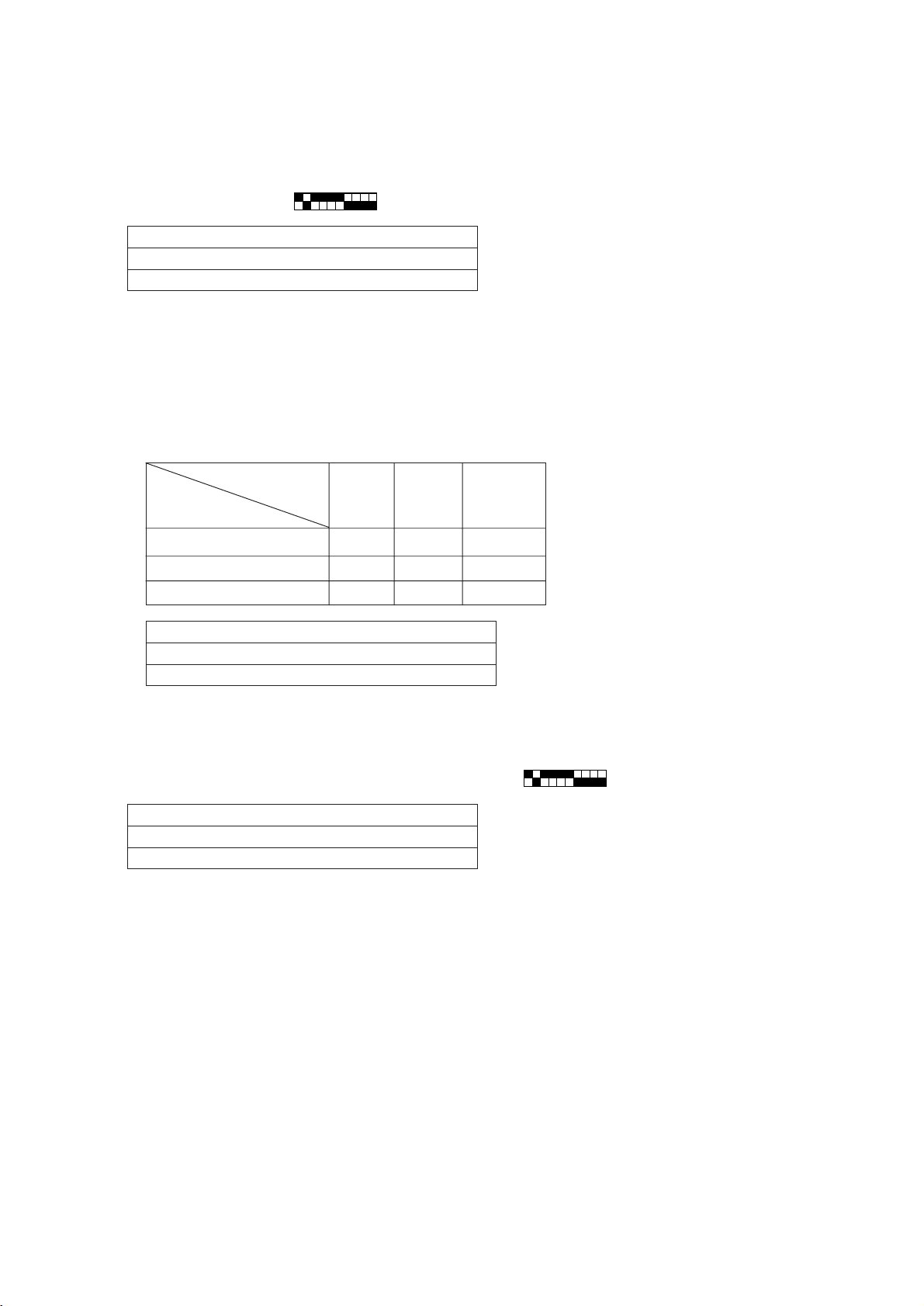
Note :
1. Be sure to operate all indoor units because refrigerant is accumulated in stopped unit. Change mode to test run
mode for preventing stabilized operations from being disturbed by turning thermostat.
2. • Judge operation status as “stable” when high pressure is stabilized.
• Judge “stable” or “unstable” 3 minutes after starting compressor.
3. When turning on SW1 to
1234 567 8910
ON
, LED displays liquid level as follows.
When LED 1 lights up → AL=0
When LED 2 lights up → AL=1
When LED 3 lights up → AL=2
4. In the case of AL=1, adjustment is not required in principle. However, if liquid level is on the lower side, adjustment
is required for fear of refrigerant shortage because refrigerant is accumulated in stopped unit at the time on oneunit operations.
5. Calculate difference of required refrigerant amounts between cooling and heating operations.
1 In case refrigerant piping length is roughly known
Replenish refrigerant observing the table below.
The total. length is that converted to ø19.05 liquid pipe size.
High pressure
2
G) (MPa)
(kg/cm
Piping length (m)
15 or less 15~17 17 or more
(1.47)
(1.47~1.67)
(1.67)
60m or less 10kg 5kg 2kg
60~90m 11kg 6kg 3kg
90m or more 12kg 7kg 4kg
Liquid pipe size ø12.7 → Actual length × 0.75
Liquid pipe size ø9.52 → Actual length × 0.375
Liquid pipe size ø6.35 → Actual length × 0.15
2 In case refrigerant piping length is not known
Additionally charge 10kg refrigerant.
1234 567 8910
6. When turning on SW, LED shows liquid level displayed mode.
ON
When LED 1 lights up → AL=0
When LED 2 lights up → AL=1
When LED 3 lights up → AL=2
7. When 7~B adjustments has been done without fail, AL=2 is not indicated even though maximum amount of
refrigerant is charged at C. Therefore, when AL=2 is displayed, excessive replenishment at 7 and 9, or calculation mistaken in C are judged as the cause.
–74–
Page 78

77
7 TROUBLESHOOTING
77
[1] Principal Parts
Pressure sensor
(1) Judging failure
1) Check for failure by comparing the sensing pressure according to the high pressure/low pressure pressure sensor
and the pressure gauge pressure.
Turn on switches 1, 3, 5, 6 (High) and 2, 4, 5, 6 (Low) of the digital display select switch (SW1) as shown below, and
the sensor pressure of the high pressure/low pressure sensors is displayed digitally by the light emitting diode LD1.
1234 56 78910
High pressure
Low pressure
1 In the stopped condition, compare the pressure readings from the gauge and from the LD1 display.
(a) If the gauge pressure is 0~1 kg/cm
(b) If the pressure according to the LD1 display is 0~1 kg/cm
tor, or it is disconnected. Proceed to 4.
(c) If the pressure according to the LD1 display is 32 kg/cm
(d) If other than (a), (b) or (c), compare the pressure readings during operation. Proceed to 2.
ON
1234 56 78910
ON
2
G (0.098MPa), the internal pressure is dropping due to gas leakage.
2
G (0.098MPa), there is faulty contact at the connec-
2
G (3.14MPa) or higher, proceed to 3.
2 Compare the pressure readings from the gauge and from the LD1 display while in the running condition.
(a) If the difference between the two pressures is within 1 kg/cm
2
G (0.098MPa), both the affected pressure sensor
and the main MAIN board are normal.
(b) If the difference between the two pressures exceeds 1 kg/cm
2
G (0.098MPa), the affected pressure sensor is
faulty (deteriorating performance).
(c) If the pressure reading in the LD1 display does not change, the affected pressure sensor is faulty.
3 Disconnect the pressure sensor from the MAIN board and check the pressure according to the LD1 display.
(a) If the pressure is 0~1 kg/cm
2
G (0.098MPa) on the LD1 display, the affected pressure sensor is faulty.
(b) If the pressure is 32 kg/cm2G (3.14MPa) (in the case of the low pressure sensor, 10 kg/cm2G (0.98MPa)) or
higher, the MAIN board is faulty.
4 Disconnect the pressure sensor from the MAIN board and short out the No. 2 and No. 3 pins of the connector
(63HS, 63LS), then check the pressure by the LD1 display.
(a) If the pressure according to the LD1 display is 32 kg/cm
2
G (3.14MPa) (in the case of the low pressure sensor,
10 kg/cm2G (0.98MPa)) or higher, the affected pressure sensor is faulty.
(b) If other than (a), the MAIN board is faulty.
2) Pressure sensor configuration.
The pressure sensors are configured in the circuit shown in the figure at right. If DC 5 V is applied between the red
and black wires, a voltage corresponding to the voltage between the white and black wires is output and this voltage
is picked up by the microcomputer. Output voltages are as shown below.
High pressure 0.1 V per 1 kg/cm
2
G (0.098MPa)
Low pressure 0.3 V per 1 kg/cm2G (0.098MPa)
–75–
Connector
63HS/
63LS
Vout 0.5~3.5 V
GND (Black)
Vout (White)
Vcc (DC5V) (Red)
Page 79

* Connector connection specifications on the pressure sensor body side.
The connector’s pin numbers on the pressure sensor body side differ from the pin numbers on the main circuit board
side.
Sensor body side MAIN board side
Vcc Pin 1 Pin 3
Vout Pin 2 Pin 2
GND Pin 3 Pin 1
Solenoid valve (SV1~6, SV71~73)
Check if the control board’s output signals and the operation of the solenoid valves match.
Setting the self-diagnosis switch (SW1) as shown in the figure below causes the ON signal of each relay to be output to
the LED’s.
Each LED shows whether the relays for the following parts are ON or OFF. When a LED lights up, it indicates that the
relay is ON.
SW1
1234 56 78910
ON
1234 56 78910
ON
12345678
SV6SV5
LED
SV4SV3SV2SV1
SV73SV72SV71
1) In the case of SV1 (Bypass Valve)
(a) When the compressor starts, SV1 is ON for 4 minutes, so check operation by whether the solenoid valve is
emitting an operating noise.
(b) Changes in the operating condition by solenoid valve operation can be confirmed by the temperature of the
bypass circuit and the sound of the refrigerant.
2) In the case of SV2 (Bypass)
(a) SV2 goes ON in accordance with the rise in the high pressure in the cooling mode and heating mode, so check
its operation by the LED display and the operating noise emitted by the solenoid valve.
(Conditions during operation: See Control of Heat Source Unit.)
(b) Changes in the operating condition by solenoid valve operation can be confirmed by the temperature of the
bypass circuit and the sound of the refrigerant.
3) SV3~6, SV71~73 (Control of heat exchanger capacity)
(a) Operations can be confirmed by LED display and operating sound of solenoid valve, because one or more of
SV3~5, SV71 are turned on depending on conditions during cooling-only operations.
(b) Operation can be confirmed by LED display and operating sound of solenoid valve, because all of SV3~5, SV73
are turned on during heating-only operations.
(c) Operations can be confirmed by LED display and operating sound of solenoid valve, because one or more of
SV3~6, SV71~73 are turned on depending on conditions during cooling-principal and heating-principal operations.
–76–
Page 80

(d) The refrigerant flow is as following figure. Hot gas (high pressured) flows in cooling mode and cool gas/liquid
(low pressured) flows in heating mode. Please refer to the Refrigerant Circuit Diagram.
And, ON/OFF of Solenoid valve is depends on the amount of running indoor units, ambient temperature and so
on. So please check by LED Monitor Display.
The SV coil is taken off, then it is possible to open caps and check plungers. But the special tool which is on the
Service Parts List is needed.
Solenoid Valves
Block
SV3
SV4
➁➂➃➄➅
HEXA
HEXB HEXC HEXD HEXE
➀
Distributor
SV5
CV9CV8
SV6
CV10
SV71
CV4
CV5
CV6
Orifice
CV7
CV2
CV3
* Closed torque : 13kg·m (1.3N·m)
–77–
Page 81

LEV for heat source unit
The valve opening angle changes in proportion to the number of pulses.
(Connections between the heat source unit’s MAIN board and SLEV, LEV2)
Pulse signal output and valve operation
Output (phase)
Output states
1234567 8
ø1 ON OFF OFF OFF OFF OFF ON ON
ø2 ON ON ON OFF OFF OFF OFF OFF
ø3 OFF OFF ON ON ON OFF OFF OFF
ø4 OFF OFF OFF OFF ON ON ON OFF
LEV valve closing and valve opening operations
Valve Closing
Valve Opening
Valve Opening Angle (Flow Rate)
Fully Open
480 pulses
Output pulses change in the following orders when the
Valve is Closed 1→2→3→4→5→6→7→8→1
Valve is Open 8→7→6→5→4→3→2→1→8
*1. When the LEV opening angle does not change, all the
output phases are off.
2. When the output is out of phase or remains ON
continuously, the motor cannot run smoothly, but move
jerkily and vibrates.
* When the power is switched ON, a 520 pulse valve
opening signal is output to make sure the valve’s
position, so that it is definitely at point A. (The pulse
signal is output for approximately 17 seconds.)
* When the valve operates smoothly, there is no sound
from the LEV and no vibration occurs, but when the
valve is locked, it emits a noise.
* Whether a sound is being emitted or not can be
determined by holding a screwdriver, etc. against it,
then placing your ear against the handle.
* If there is liquid refrigerant inside the LEV, the sound
may become lower.
Pulse Count
–78–
Page 82

LEV for BC controller and indoor unit
1 LEV receives pulse signal from microcomputer, and operates valve with stepping motor.
2 Valve opening changes in proportion to the number of pulses.
Connection of microcomputer circuit board and LEV
Intermediate connector
(mounted on outdoor unit only)
Brown
Red
Blue
Orange
Yellow
White
Connector
In the case of indoor board : CN60
In the case of multi board : CNLV
Microcomputer circuit boad
Operarion
circuit
Note:
Pay attention to colors of lead wires
because numbers of intermediate connectors are different from those of circuit board
side connectors.
Pulse signal output and valve operations
Output (phase)
No.
ø1
ø2
ø3
ø4
OFF ON ON OFF
OFF OFF ON ON
Output states
123 4
ON OFF OFF ON
ON ON OFF OFF
Closing and opening operations of valve
D
e
v
l
a
g
in
s
Valve opening (Flow rate)
A
lo
c
e
lv
a
V
E
V
g
in
n
e
p
o
C
Full opening
(2000 pulses)
1 Valve open : Output pulse changes in order of 1→2→3→4→1.
Valve close : Output pulse changes in order of 4→3→2→1→4.
2 All output phases are turned OFF when LEV opening does not
change.
3 In case output phase is lacking or kept “ON,” motor can not rotate
smoothly, generating ticking sound and vibration.
1 When turning on power source, issue valve closing signal of 2,200
pulses, so that valve opening is located at point A.
2 When valve runs smoothly, no sound or vibration is generated from
LEV. However, big sound is observed when valve opening changes
from point E to A or valve is locked.
(Sound generation can be identified from the bundle of screwdriver
attached to the valve.)
B
Additional tightening zone
(870 ~ 100 pulses)
Number of
pulse(SJ)
–79–
Page 83

Judgment methods and likely failure mode
Caution:
The specifications of the heat source unit (heat source LEV) and indoor unit (indoor LEV) differ. For this reason,
there are cases where the treatment contents differ, so follow the treatment specified for the appropriate LEV as
indicated in the right column.
Failure Mode Judgment Method Treatment Affected LEV
Microcomputer
driver circuit
failure
1 Disconnect the control board connector and connect
the check LED as shown in the figure below.
Indoor, BC controller
When the base power supply is turned on, the indoor LEV
outputs pulse signals for 10 seconds, the heat source LEV
outputs pulse signals for 17 seconds, and BC controller
outputs pulse signals for 10-20 seconds.
If the LED does not light up, or lights up and remains on,
the driver circuit is abnormal.
Heat source
In the case of driver circuit
failure, replace the control
board.
Indoor
BC controller
Heat source
LEV mechanism
is locked.
The LEV motor
coils have a
disconnected wire
or is shorted.
Fully closed
failure (valve
leaks)
1 If the LEV is locked up, the drive motor turns with no
load and a small clicking sound is generated.
Generation of this sound when the LEV is fully closed
or fully open is abnormal.
Measure the resistance between the coils (red - white, red
- orange, brown - yellow, brown - blue) using a tester. They
are normal if the resistance is within 150Ω ± 10%.
Measure the resistance between the coils (gray - orange,
gray - red, gray - yellow, gray - black) using a tester. They
are normal if the resistance is within 46Ω ± 3%.
1 If you are checking the indoor unit’s LEV, operate the
indoor unit’s blower and the other indoor units in the
cooling mode, then check the piping temperatures
(liquid pipe temperatures) of the indoor units by the
operation monitor through the heat source unit’s
control board. When the fan is running, the linear
expansion valve is fully closed, so if there is leakage,
Thermistor
liquid pipe
(temperature sensor)
Linear
Expansion
Valve
minimal leakage, it is not necessary to replace the
LEV if there are no other effects.
the temperature sensed by the
thermistor (liquid pipe temperature
sensor) will become low. If the
temperature is considerably low
compared to the remote control’s
intake temperature display, it can
be judged that there is a fully
closed failure. In the case of
Replace the LEV.
Replace the LEV coils.
Replace the LEV coils.
If there is a large amount of
leakage, replace the LEV.
Indoor
BC controller
Heat source
Indoor
BC controller
Heat source
Indoor
BC controller
Faulty wire
connections in
the connector or
faulty contact.
1 Check for pins not fully inserted on the connector and
check the colors of the lead wires visually.
2 Disconnect the control board’s connector and conduct
a continuity check using a tester.
–80–
Check the continuity at the
places where trouble is found.
Indoor
BC controller
Heat source
Page 84

Heat source LEV (SLEV) coil removal procedure (configuration)
As shown in the figure, the heat source LEV is made in such a way that the coils and the body can be separated.
Coils
Stopper
Lead wires
<Removing the coils>
Fasten the body tightly at the bottom (Part A in the figure) so
that the body will not move, then pull out the coils toward the
top. If they catch on the stopper and are difficult to take out,
turn the coils left and right until the stoppers are free from the
stopper indentations, then pull the coils out.
If you take out the coils only without gripping the body, undue
force will be applied to the piping and the pipe may be bent
over, so be sure to fasten the body in such a way that it will not
move.
Body
Indentation for
Stopper
(12 places around
the circumference)
Part A
<Installing the coils>
Fasten the body tightly at the bottom (Part A in the figure) so
that the body will not move, then insert the coils from the top,
inserting the coils’ stopper securely in one of the indentations
on the body. (There are four indentations for the stopper on
the body around its circumference, and it doesn’t matter which
indentation is used. However, be careful not to apply undue
force to the lead wires or twist them around inside the body.) If
the coils are inserted without gripping the body, it may exert
undue force on the piping, causing it to become bent, so be
sure to hold the body firmly so that it won’t move when installing the coils.
Part A
–81–
Page 85

Check valves block (PURY-P200·250YMF-B)
The refrigerant flow in the pipe 6, 7, 8 and 9 are depend on ON/OFF of the SV3, 4, 5 and 6.
Please confirm by LED monitor display.
You can open the cap of valve A, B and C, but 3 types of hexagon socket screw keys. The size is as follows.
Distributor
SV3
SV4
SV5
SV6
HEXA
HEXB HEXC HEXD HEXE
ST7b ST7cST7a
CV7
TH6
SV71
ST7d
CV9CV8
CV10
Check Valves Block
➄➅➆➇➈ ➉
CV4
CV6
Orifice
CV5
CV2
➀➁➂
CV3
BV1
➃
ST1
BV2
* Closed torque : A : 1.7kg·m (0.17N·m)
B : 20kg·m (2.0N·m)
C : 13kg·m (1.3N·m)
–82–
Page 86

Power transistor
C
B
E
Measure resistances between each terminal of transistor module with tester, and use the results for troubleshooting.
Specified resistance value is dependent on tester type to be used for resistance measurement, because diode
transistor has non-linearity, thus difference of impedance and voltage in tester being influential. As the internal
impedance of resistance range of analog tester equals to the center value of meter indication, the affect of internal
impedance can be minimized if the tester having close center value of resistance range. Because internal voltage is
normally 1.5V, the tester to be used for troubleshooting of transistor module should satisfy the following conditions.
Internal voltage 1.5V (Power source : one dry cell battery)
Central value of resistance range 10 ~ 40Ω
The measured values for troubleshooting are shown in the table below.
(Use the minimum range for tester resistance range.)
C1
B1
Transistor module has 6
circuits shown in the left.
(See figure below)
E1 C2,E1
E2
B2
E2
Tester -
Tester ⊕
C ∞∞
B 2~100Ω 100~1500Ω
E 2~100Ω 100~1500Ω
CB E
Diode stack
Perform continuity check with tester. Judged as normal if the following characteristics are observed.
(Use the minimum range for tester resistance range.)
123
+
Tester -
Tester
⊕
Tester ⊕
1 10~50Ω∞
2 10~50Ω∞
3 10~50Ω∞
Tester -
1 ∞ 10~50Ω
2 ∞ 10~50Ω
3 ∞ 10~50Ω
+–
+–
1
2
3
–
–83–
Page 87

(5) Trouble and remedy of remote controller
Symptom Cause Checking method & countermeasure
1
Despite pressing of
remote controller
switch, operation
does not start with
no electronic sound.
(No powering signal
appears.)
2
At about 10 seconds
after turning remote
controller operation
switch ON, the
display distinguishes
and the operation
stops.
1) M-NET transmission power source is not supplied
from heat source unit.
1 Main power source of heat source unit is not
connected.
2 Slipping off of connector on heat source unit circuit
board.
Main board : CNS1, CNVCC3
INV board : CNAC2, CNVCC1, CNL2
3 Faulty power source circuit of heat source unit.
• Faulty INV board,
• Blown fuse (F1 on INV board)
• Broken diode stack
• Broken resistor (R1) for rush current protection
2) Short circuit of transmission line.
3) Erroneous wiring of M-NET transmission line at heat source unit.
1 Transmission line disconnection or slipping off from terminal
block.
2 Erroneous connection of indoor/outdoor transmission line to
TB7.
4) Slipping off of transmission wiring at remote controller.
5) Faulty remote controller.
1) Power source is not fed to indoor unit from transformer.
1 Main power source of indoor unit is not turned on.
2 Slipping off of connector (CND, CNT, CN3T) on indoor controller board.
3 Blown fuse on indoor controller board.
4 Faulty or disconnected transformer of indoor unit.
5 Faulty indoor controller board.
2) Faulty outdoor control circuit board or being out of control.
As normal transmission is failed between indoor and heat source units, heat source unit model can
not be recognized.
a) Check transmission terminal block of
remote controller for voltage.
i) In case of 17 ~ 30V
→ Faulty network remote controller
ii) In case of less than 17V
→ See “Transmission Power Circuit
(30V) Check Procedure”.
The cause of 2) and 3) is
displayed with self-diagnosis
LED for 7102 error.
Checking method & countermeasure
Check indoor LED3
Lighting?
Lighting
Check for the change of LED
display by operating dip switch
SW1 for self-diagnosis.
Extinguishing or
unable to confirm
Check indoor unit
power source terminal
block voltage
AC 220~240V?
YES
Check fuse on circuit
board
Blown?
NO
Check connector slipping
off (CND, CNT, CN3T)
Slipped off?
NO
Check transformer
resistance value
Within rated?
YES
Check self-diagnosis function of heat source unit
Changed?
NO
YES
YES
*1
NO
NO
Check main power source
of power source wiring.
Check 220V~240V
circuit for short circuit
and ground fault.
Improper connector
connection
Check cause of transformer disconnection.
•Ground fault on circuit
board
•Ground fault on
sensor, LEV
Apply power
source again.
Check self-diagnosis function after
powering heat source unit again.
NO
Faulty heat source unit
control circuit board
Repair
faulty point.
YES
Faulty indoor
controller board
Changed?
YES
Casual
trouble
*1 Check the transformer in accordance with the “TROUBLE SHOOTING” in the indoor unit’s service handbook.
–84–
Page 88

Symptom Cause
3 “HO” display on re-
mote controller does
not disappear and
switch is ineffective.
(Without using MELANS)
1) Heat source unit address is set to “000.”
2) Erroneous address.
1 Address setting miss of indoor unit to be coupled with remote controller.
2 Address setting miss of remote controller.
3) Faulty wiring of transmission terminal block TB5 of indoor unit in the same group with remote
controller.
4) Centralized control SW2-1 of heat source unit is turned ON.
5) Setting to interlocking system from indoor unit (Switch 3-1 = OFF), while Fresh Master is intended to
use by remote controller operation (indoor unit attribute).
6) Disconnection or faulty wiring of indoor unit transmission line.
7) Disconnection between indoor unit M-NET transmission line terminal block (TB5) and connector
CN2M.
8) More than 2 sets of power supply connector (CN40) are inserted into centralized control transmission line of heat source unit.
9) Faulty heat source unit control circuit board.
10)Faulty indoor controller board.
11)Faulty remote controller.
(Interlocking control with MELANS)
12)No grouping registration from MELANS (Neglecting to set the relation between indoor unit and
network remote controller).
13)Slipping off of centralized control transmission line (TB7) at heat source unit.
14)At system connected with MELANS, power supply connector (CN40) is inserted to centralized
control transmission line of heat source unit.
Checking method & countermeasure
(Indoor unit = remote controller - 100.)
(Remote controller = indoor unit + 100.)
In case no MELANS used
Same symptom for all
units in a single refrigerant system?
YES
Check heat source
unit address
51 ~ 100?
YES
Check centralized
control switch SW2-1 at
heat source unit
ON?
NO
Faulty heat source unit
control circuit board
NO
NO
YES
Heat source
unit address
setting miss
Switch setting
miss
Make it ON
→ OFF
Address setting
miss of remote
controller
Indoor address
setting miss
Transmission line
wiring miss of indoor unit M-NET
Slipping off of
CN2M
connector
Confirm address of remote
controller with “HO” displayed
Indoor unit + 100?
Check address of
coupling indoor unit
Remote controller
-100?
YES
Check voltage of indoor unit MNET transmission terminal block
17 ~ 30V?
Check connection between indoor unit M-NET transmission terminal block (TB5) and connector CN2M
YES
Check Fresh Master SW3-1
YES
Slipping off?
NO
NO
Faulty indoor controller board
or remote controller
ON?
YES
Repair spot
in trouble
Setting miss of
Fresh Master
SW3-1
In case with MELANS used
When MELANS is used, “HO” display on the remote controller will disappear at the group registration of the indoor unit and local
remote controller.
If “HO” does not disappear after the registration, check the items 12) ~ 14) in the Cause column.
–85–
Page 89

Symptom Cause Checking method & countermeasure
4 “88” appears on re-
mote controller at the
registration and
access remote
controller
[Generates at registration and confirmation]
1) Erroneous address of unit to be coupled.
2) Slipping off of transmission line of unit to be coupled
(No connection).
3) Faulty circuit board of unit to be coupled.
4) Installation miss of transmission line.
a) Confirm the address of unit to be
coupled.
b) Check the connection of transmission
line.
c) Check the transmission terminal block
voltage of unit to be coupled.
i) Normal if voltage is DC17 ~ 30V
ii) Check the item d) in case other than i).
[Confirmation of different refrigerant system controller]
5) Breaking of power source of heat source unit to be
confirmed.
6) Slipping off of centralized control transmission line
(TB7) of heat source unit.
7) Power supply connector (CN40) is not inserted into
centralized control transmission line in grouping
with different refrigerant system without using
MELANS.
8) More than 2 sets of power supply connector are
inserted into the centralized control transmission line
of heat source unit.
9) In the system connected with MELANS, power
supply connector (CN40) is inserted into the
centralized control transmission line of heat source
unit.
10)Short circuit of centralized control transmission line.
d) Confirm the power source of heat source
unit to be coupled with the unit to be
confirmed.
e) Confirm that the centralized control
transmission line (TB7) of heat source
unit is not slipped off.
f) Confirm the voltage of centralized control
transmission line.
i) Normal in case of 10V ~ 30V
ii) Check the items 7) ~ 10) left in case
that other than i).
–86–
Page 90

Transmission power circuit (30 V) check procedure
If “” is not displayed by the remote control, investigate the points of the trouble by the following procedure and correct it.
No. Check item Judgment Response
1
Disconnect the transmission line from TB3
and check the TB3 voltage.
DC24~30 V
Check the transmission line for the following, and
correct any defects.
Broken wire, short circuit, grounding, faulty
contact.
2
Check if the following connectors are
disconnected in the heat source unit’s
control box.
MAIN Board: CNS1, CNVCC3
INV Board: CNVCC1, CNL2, CNR,
CNAC2
3
Disconnect the wires from CNVCC3 on the
Main board and check the voltage between
pins 1 and 3 on the wire side of the
CNVCC3.
Tester + ..... 1 pin
Tester - ..... 3 pin
4
Disconnect the wiring from CNVCC2 on the
INV board and check the voltage between
pins 1 and 3 of CNVCC2.
Tester + ..... 1 pin
Tester - ..... 3 pin
5
Disconnect the wiring from CNL2 on the
INV board, and check the resistance at
both ends of choke coil L2.
6
Disconnect the wiring from CNR on the INV
board, and check the resistance at both
ends of R7.
Except the above-mentioned
Connector disconnected
Except the above-mentioned
DC24~30 V
Except the above-mentioned
DC24~30 V
Except the above-mentioned
0.5~2.5Ω
Except the above-mentioned
19~25Ω
Except the above-mentioned
to No. 2
Connect the connectors as shown on the electric
wiring diagram plate.
to No. 3
Check the wiring between CNS1 and TB3 for the
following, and correct any defects.
Broken wire, short circuit, grounding, faulty
contact.
If there is no trouble, replace the Main board.
to No. 4
Check the wiring between CNVCC2 and
CNVCC3 for the following, and correct any
defects.
Broken wire, short circuit, grounding, faulty
contact.
to No. 5
to No. 6
Replace choke coil L2.
to No. 7
Replace R7.
7
Check the resistance at both ends of F01
on the INV board.
8
Check the voltage between pins 1 and 3 of
CNAC2 on the INV board.
9
Check the voltage between L2 and N on
power supply terminal block TB1.
0Ω
Except the above-mentioned
AC198~264 V
Except the above-mentioned
AC198~264 V
Except the above-mentioned
to No. 8
Replace F01
Replace the INV board.
to No. 9
Check the wiring to CNAC2 for the following and
correct any defects.
Broken wire, faulty contact.
Check the power supply wiring and base power
supply, and correct any defects.
–87–
Page 91

(6) Investigation of transmission wave shape/noise
Control is performed by exchanging signals between heat source unit, indoor unit and remote controller by M-NET
transmission. If noise should enter into the transmission line, the normal transmission will be hindered causing
erroneous operation.
1) Symptom caused by the noise entered into transmission line
Cause Erroneous operation Error code
Noise entered into
transmission line
Signal changes and is misjudged as the signal of other
address.
Transmission wave shape changes to other signal due to
6600
6602
noise.
Transmission wave shape changes due to noise, and can
6607
not be received normally thus providing no reply (ACK).
Transmission can not be made continuously due to the
6603
entry of fine noise.
Transmission can be made normally, but reply (ACK) or
answer can not be issued normally due to noise.
6607
6608
2) Method to confirm wave shape
No fine noise allowed *1
<with transmission>
<without transmission>
VHL
52 µs
Logical
VBN
52 µs
value “0”
Logical
52 µs
value “1”
52 µs52 µs
No fine noise allowed *1
Check the wave shape of transmission line with an oscilloscope to confirm that the following conditions are being
satisfied.
1 The figure should be 104µs/bit ± 1%.
2 No finer wave shape (noise) than the transmission signal (52µs ± 1%) should be allowed. *1
3 The sectional voltage level of transmission signal should be as follows.
Logic value Transmission line voltage level
0VHL = 2.0V or more
1VBN = 1.3V or less
*1 However, minute noise from the DC-DC converter or inverter operation may be picked up.
–88–
Page 92

3) Checking and measures to be taken
(a) Measures against noise
Check the items below when noise can be confirmed on wave shape or the error code in the item 1) is generated.
Items to be checked Measures to be taken
1 Wiring of transmission and power lines in
crossing.
2 Wiring of transmission line with that of other
system in bundle.
3 Use of shield wire for transmission line (for
both indoor unit control and centralized
control).
4 Repeating of shield at the repeating of
transmission line with indoor unit.
Checking for wiring method
5 Are the unit and transmission lines grounded
as instructed in the INSTALLATION MANUAL?
6 Earthing of the shield of transmission line (for
indoor unit control) to heat source unit.
7 Arrangement for the shield of transmission line
(for centralized control).
Check for earthing
Isolate transmission line from power line (5cm or more).
Never put them in a same conduit.
Wire transmission line isolating from other transmission line.
Wiring in bundle may cause erroneous operation like crosstalk.
Use specified transmission wire.
Type : Shield line CVVS/CPEVS
Wire diameter : 1.25mm
The transmission line is wired with 2-jumper system. Wire the shield
with jumper system as same for transmission line.
When the jumper wiring is not applied to the shield, the effect against
noise will be reduced.
Connect to ground as shown in the INSTALLATION MANUAL.
One point earthing should be made at heat source unit.
Without earthing, transmission signal may be changed as the noise on
the transmission line has no way to escape.
For the shield earth of the transmission line for centralized control, the
effect of noise can be minimized if it is from one of the heat source units
in case of the group operation with different refrigerant systems, and
from the upper rank controller in case the upper rank controller is used.
However, the environment against noise such as the distance of transmission line, the number of connecting sets, the type of connecting controller, and the place of installation, is different for the wiring for centralized control. Therefore, the state of the work should be checked as follows.
a) No earthing
• Group operation with different refrigerant systems
One point earthing at heat source unit
• Upper rank controller is used
Earthing at the upper rank controller
b) Error is generated even though one point earth is being con-
nected.
Earth shield at all heat source units.
2
or more
Connect to ground as shown in the user’s manual.
(b) When the wave height value of transmission wave shape is low, 6607 error is generated, or remote controller is
under the state of “HO.”
Items to be checked Measures to be taken
8 The farthest distance of transmission line is
exceeding 200m.
9 The types of transmission lines are different.
0 No transmission power (30V) is being supplied
to the idoor unit or the remote control.
A Faulty indoor unit/remote controller.
Confirm that the farthest distance from heat source unit to indoor unit/
remote controller is less than 200m.
Use the transmission wire specified.
Type of transmission line : Shield wire CVVS/CPEVS
Wire dia. of transmission line : 1.25mm2 or more
Refer to “Transmission Power Supply (30V) Circuit Check Procedure.”
Replace heat source unit circuit board or remote controller.
–89–
Page 93

4) Treatment of inverter and compressor troubles
If the compressor does not work when error codes 4210, 4240, 4310 or 4340 are detected, determine the point of
malfunction by following the steps in the LED monitor display and countermeasures depending on the check
code displayed, then perform the procedures below.
No. Check Item Symptoms Treatment
How many hours was the
power kept on before
1
operation?
1 If it was kept on for 12 hours or
longer as specified.
2 It was kept on for less than the
specified period.
Go to [2].
Go to [2] after keeping the power on for the
specified time.
When it is restarted, does
2
the trouble reappear?
3
Run the heat source unit
with the wiring to the
compressor disconnected.
At this time, change SW1-1
on the INV board to ON.
Note) The terminals of the 3
disconnected wires should
be isolated from each other.
*1 [Cautions when measuring the voltage and current of the inverter’s power circuit.]
1 The compressor stops and the
same error code is displayed.
1 The compressor stops and the
same error code is displayed.
2 If the inverter’s output voltage is
output with good balance, *1.
3 If the balance in the inverter’s
output voltage is not good or if the
inverter’s output voltages are all 0 V
(a digital tester cannot be used) *1.
Perform the check of wiring shown in the
explanation of each error code.
Check the transistor module is faulty. (Go to
“Individual Parts Failure Judgment Methods.”)
Check the coil resistance and insulation
resistance of the compressor, and if it is
normal, run it again, and if the trouble occurs
again, replace the compressor.
* Insulation resistance : 2MΩ or more
Coil resistance : 0.359 ~ 0.716Ω
Check the transistor module.
Judge that the transistor module is faulty.
(Go to “Individual Parts Failure Judgment
Methods.”)
If the transistor module is normal, replace
the INV board, then perform this item again
with SW1-1 ON. If the problem is solved and
you connect the compressor again, turn
SW1-1 OFF again. Check the compressor’s
coil resistance and insulation resistance.
Since the voltage and current on the inverter’s power supply side and its output side do not have a sine waveform, the
measurement values will differ depending on the measuring instrument and the circuit measured.
In particular, as the inverter’s output voltage has a pulse waveform, the output frequency also changes, so differences in
measurement values will be great depending on the measuring instrument.
1 When checking if the inverter’s output voltage is unbalanced or not (relative comparison of the voltages between
each of the lines), if you are testing with a portable tester, be sure to use an analog tester.
Use a tester of a type which can be used to judge if the transistor module or diode module is faulty.
In particular, in cases where the inverter’s output frequency is low, there are cases where the variations in measured
voltage values between the different wires will be great when a portable digital tester is used, when in actuality they
are virtually equal, and there is danger of judging that the inverter is faulty.
2 It is recommended when checking the inverter’s output voltage values (when measuring absolute values), that, if a
measuring device for business frequencies is used, a rectified voltage meter (with a
Correct measurement values cannot be obtained with an ordinary portable tester. (either analog or digital)
symbol) be used.
–90–
Page 94

5) Troubleshooting at breaker tripping
Check items Measures to be taken
1 Check the breaker capacity.
The breaker’s capacity should be proper.
2 Check the a short circuit or grounding in the electrical
system other than the inverter.
3 Check the resistance between terminals on the terminal
block TB1A for power source.
1 0 ~ several ohms or improper megohm value
4 Checking by powering again.
1 Main power source circuit breaker tripping
2 No display of remote controller
5 Operational check by operating air conditioner
Correct any defects.
Check each part inside the inverter power circuit
(resistance, megohm or the like).
a) Diode stack
Refer to “Troubleshooting of diode stack.”
b) Power transistor
Refer to “Troubleshooting of power transistor.”
c) Rush current protection resistor
d) Electromagnetic contactor
e) DC reactor
* For c) ~ e), refer to “Individual Parts Failure Judge-
ment Methods.”
1 Normal operation without breaker tripping.
2 Breaker tripping
a) As there is a possibility of instantaneous short
circuit generated, find the mark of the short circuit
for repair.
b) When a) is not applicable, the compressor may be
faulty.
The ground fault of inverter output/compressor can
be supposed.
Disconnect the wiring to the compressor and check
the insulation resistance of the following parts with
a megger.
a) Compressor terminals.
b) Inverter output.
–91–
Page 95

6) Individual parts failure judgment methods.
Part name Judgment method
Diode Stack (DS) Refer to “Judging Diode Stack Failure.”
Transistor Module (TRM) Refer to “Judging Transistor Module Failure.”
Electromagnetic Contactor (52C) Measure the resistance value at each terminal.
A1A2
1/L1 3/L2 5/L3
Check Location Judgment Value
A1-A2 0.1k~1.3kΩ
1/L1-2/T1 ∞
3/L2-4/T2
2/T1 4/T2 6/T3
Rush current protection resistor (R1, 5) Measure the resistance between terminals: 4.5k~5.5kΩ
DC reactor (DCL) Measure the resistance between terminals: 1 Ω or lower
Measure the resistance between the terminals and the chassis: ∞
Cooling fan (MF1) Measure the resistance between terminals: 0.1k~1.5kΩ
5/L3-6/T3
Transformer (T01) Measure the resistance between terminals on the primary side (CNTR1):
1.0k~2.5kΩ
Measure the resistance between terminals on the secondary side (CNTR):
20~60Ω
[Caution at replacement of inverter parts]
1 The transistor module and INV board should be replaced together at the same time.
When the transistor module is damaged, the INV board may possibly be broken, and the use of the broken INV
board damages the normal transistor module. Therefore, replace the transistor module and INV board together at
the same time. However, if the INV board is damaged, judge that the transistor module is faulty, then judge whether
replacement is necessary or not.
2 Fully check wiring for incorrect and loose connection.
The incorrect or loose connection of the power circuit part wiring like transistor module and diode module causes to
damage the transistor module. Therefore, check the wiring fully. As the insufficient tightening of screws is difficult to
find, tighten them together additionally after finishing other works. For the wiring of the base for transistor module,
observe the wiring diagram below carefully as it has many terminals.
3 Coat the grease for radiation provided uniformly onto the radiation surface of transistor/diode modules.
Coat the grease for radiation on the full surface in a thin layer, and fix the module securely with the screw for
fastening. As the radiation grease attached on the wiring terminal causes poor contact, wipe it off if attached.
–92–
Page 96

–93–
Page 97

(8) Troubleshooting the major components of the BC controller
1) Pressure sensor
Pressure sensor troubleshooting flow
START
Check pressure sensor, PS1,
PS3, connectors for disconnection, looseness, or incorrect attachment.
OK?
Ye s
Unit running?
No
Ye s
Check on the LED monitor display.
• TH2 or LPS of heat source unit.
• HPS of heat source unit
• PS1, PS3 of BC controller and
confirm the following relationship
HPS > PS1
(puressure calculated value)
PS3 > LPS
OK?
Ye s
Stop the unit (compressor OFF).
At least
10 minutes passed since
stopping?
Ye s
Check PS1, PS3 on LED
monitor display and confirm
that none of the detected
pressure values is below
1kg/cm2G (0.098MPa).
Note 1
No
Note 2
No
No
Note 2
Take corrective action.
Check that refrigerant piping and transmission line
connections are in agreement between heat source
unit and BC controller.
No
OK?
Ye s
Correct refrigerant
piping and transmission line.
OK?
No
Ye s
HPS PS1 PS3 LPS
(pressure calculated
value) (The difference is
less than
1kg/cm2G
(0.098MPa)
OK?
No
Ye s
No board or pressure
sensor abnormality.
Check that refrigerant piping and
transmission line connections are
in agreement between heat
source unit and BC controller.
OK?
No
Ye s
Confirm the
following relationship PS1
PS3?
Ye s
Correct refrigerant
piping and the transmission line.
Check for the faulty connector on applicable pressure
sensor.
OK?
Remove the pressure sensor
connector from the board, and
check the pressure.
No
Pressure
range within 0 to 1kg/cm
(0.098MPa)
Short connectors 2 and 3 on the
board and check the pressure.
Pressure
of at least 32kg/cm2G
(3.14MPa) indicated?
Replace the wrong
puressure sensor by the
correct pressure sensor,
and confirm detected pressure is indicated correctly.
OK?
Yes
Yes
Note 3
Note 4
2
G
No
Repair faulty connection.
No
No
No
–94–
Change pres-
Yes
sure sensor.
Change board.
Page 98
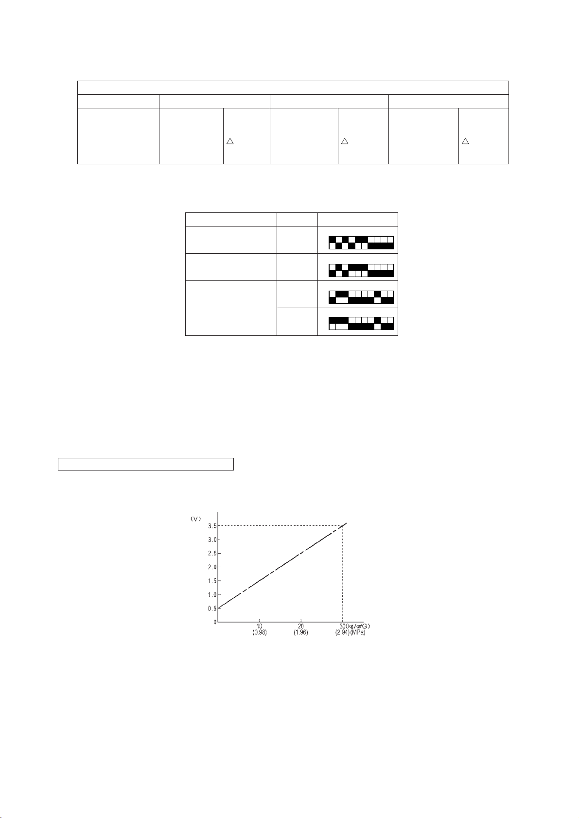
Note 1 :
• Symptoms of incorrect connection of BC controller pressure sensor to the board
Symptom
Cooling-only Cooling-principal Heating-only Heating-principal
Normal
Insufficient
cooling.
SC11 large
SC16 small
PHM < 0
Warm indoor SC
small. Warm indoor thermo ON
SC11 small
SC16 small
PHM < 0
especially noise.
Note 2 :
• Check using LED monitor display switch (heat source unit MAIN board SW1)
Insufficient heating
Warm indoor SC small
SC11 large
SC16 small
Warm indoor thermo
ON especially noise
PHM < 0
Measured Data
High pressure
Low pressure
BC controller pressure
Signal
HPS
LPS
PS1
SW1 Setting
1ON2345678910
1ON2345678910
1ON2345678910
(liquid measurement)
(intermediate)
PS3
1ON2345678910
Note 3 :
• Check CNP1 (liquid measurement) and CMP3 (intermediate) connectors on BC controller board for disconnection or
looseness.
Note 4 :
• With the sensor of the applicable connector removed from the board, use the LED monitor display switch (Note 1) to
check the pressure value.
Pressure Sensor Replacement Precaution
(Pressure sensor output voltage)
–95–
Page 99

2) Temperature sensor
Thermistor troubleshooting flow
Start
Note 1
Disconnect applicable thermistor
connector from the board.
Note 2
Measure temperature of applicable
thermistor (actual measured value).
Note 3
Check thermistor resistance value.
Compare temperature for thermistor
resistance value with actual measured valued.
No
difference?
Ye s
Insert applicable thermistor connector
into board, and check sensor input
temperature on LED monitor for difference.
No
difference?
Ye s
No abnormality
No
Note 4
No
.
Note 5
Change thermistor.
Check for connection
problem.
Change the controller
board.
–96–
Page 100

Note 1 :
• Board connector CN10 corresponds to TH11 through TH12, while connector
CN11 corresponds to TH15 through TH16. Remove the applicable connector
and check the sensor for each number.
Note 2, 3 :
1. Pull the sensor connector from the I/O board. Do not pull on the lead wire.
2. Measure resistance using a tester or other instrument.
3. Compare measured values with values on the graph below. A value within a range of ±10% is normal.
Resistance measurement point (connector)
Touch the probes of the tester or other instrument
to the shaded areas to measure.
Temperature sensor resistance (graph)
Resistance value
(kΩ)
Temperature (˚C)
Note 4 :
• Check using LED monitor display switch (outdoor MAIN board SW1)
Measured Data Signal SW1 Setting
Liquid inlet
temperature
Bypass outlet
temperature
Bypass outlet
temperature
Bypass inlet
temperature
TH11
TH12
TH15
TH16
1ON2345678910
1ON2345678910
1ON2345678910
1ON2345678910
Thermistor Ro=15 kΩ
Rt=15exp 3460 ( – )
1
273+t1273t
–97–
 Loading...