

Page 1
Electronic Multi-Measuring Instrument
MODEL
ME96SSHB-MB
User's Manual: Detailed Edition
●Before use, you should read this user’s manual carefully
to properly operate this instrument.
Be sure to forward the manual to the end user.
Page 2
Check your delivery
Contents
Quantity
Specification
I/O specifications
output
output
input
output
function
ME-4210-SS96B
4 ch
2 ch
1 ch - - -
ME-0040C-SS96
-
4 ch -
CC-Link
ME-0052-SS96
-
5 ch
2 ch - -
MODBUS
TCP
ME-0000BU-SS96
- - - -
6 items
I/O parts
Specifications
Model type
Input pulse width: 30 ms or more
ME-0052-SS96
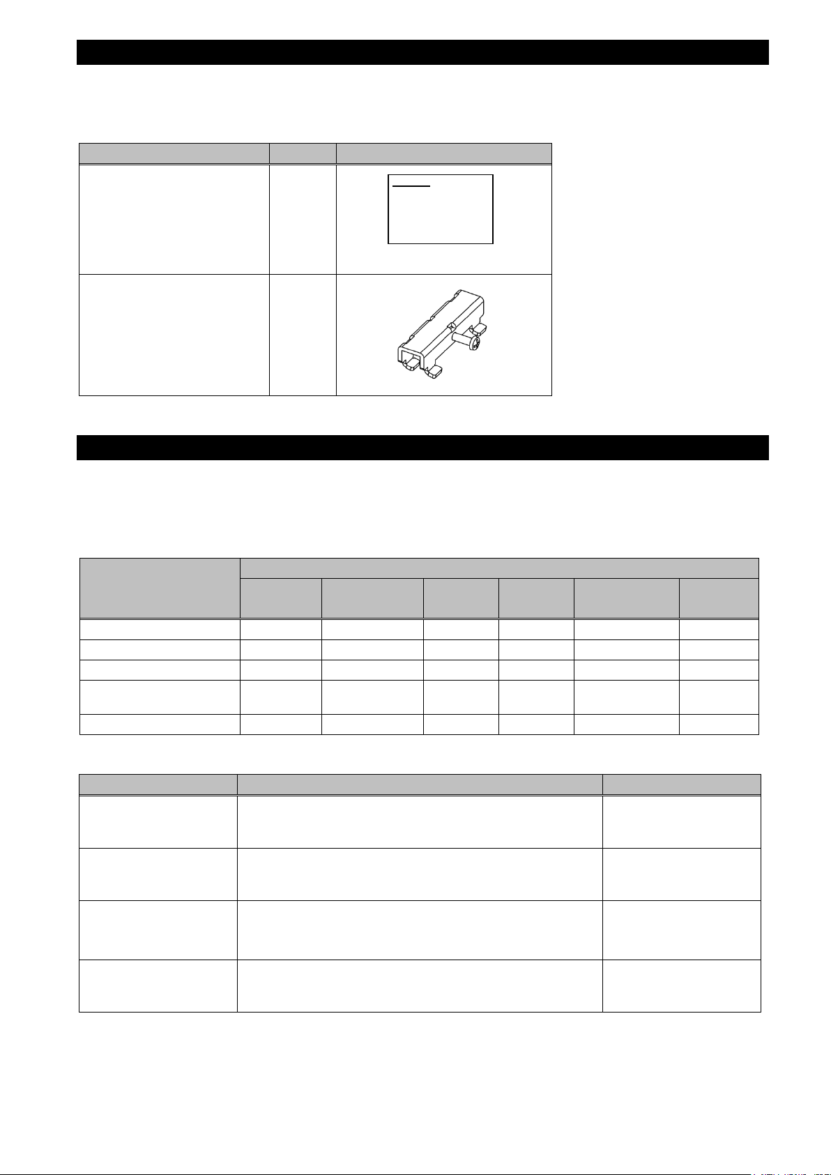
The following table shows a list of the instrument accessories.
When unpacking your package, check all the contents.
User’s Manual
(Digest version)
Attachment lug
(with a screw)
1
2
A3 size
Optional plug-in modul e
The following table shows a list of optional plug-in modules available for this product.
Installing the optional plug-in module enables various input or output. If you need it, consult with your supplier.
ME-4201-NS96, ME-0052-NS96, and ME-0040C-NS96, which are optional plug-in modules for ME96NSR and
ME96NSR-MB, are not available for ME96SSHB-MB.
Model type
ME-0000MT-SS96 - - - -
Analog output
Pulse/Alarm output
Digital input
Digital output
Analog
-
-
-
Output: 4 mA to 20 mA
Load resistance: 600 Ω or less
No-voltage a-contact
Contact capacity: 35 V DC, 0.1 A or less
Contact capacity: 24 V DC (19 V DC to 30 V DC), 7 mA
or less
No-voltage a-contact
Contact capacity: 35 V DC, 0.2 A or less
Pulse/Alarm
Digital
Digital
Communication
ME-4210-SS96B
ME-4210-SS96B
ME-4210-SS96B
ME-0040C-SS96
ME-0052-SS96
Logging
-
-
In this manual, the operation is also explained when the optional plug-in module is installed.
1
Page 3

Features
The instrument measures load status by wiring the secondary sides of VT (Voltage Transformer) and CT
(Current Transformer) in the power receiving and distribution system and displays various measured values.
The instrument supports highly accurate measurement (accuracy of current/voltage: 0.1%; active energy:
class 0.5S) and high-order harmonic measurement (1st to 31st).
Active energy can be measured by dividing into three time periods such as peak, off-peak, and shoulder.
(Periodic Acti ve Energy)
This instrument enables measurement of active energy/reactive energy/ apparent energy for any period
(interval). (Rolling demand active power/Rolling demand reactive power/Rolling demand apparent power)
The password protection prevents undesired setting change and measured data deletion.
The transmission function (MODBUS RTU communication, CC-Link communication, or MODBUS TCP
commination) transmits measured data to superior monitoring systems.
*CC-Link communication is available when ME-0040C-SS96 (optional plug-in module) is installed.
*MODBUS TCP commination is available when ME-0040C-SS96 (optional plug-in module) is installed.
The logging function enables to back up measured values in a SD memory card even when a MODB US RT U
communication error occurs.
*It is available when ME-0000BU-SS96 (optional plug-in module) is install e d.
This instrument itself can output key measuring elements such as current, voltage, active power, power
factor, and active energy at the power receiving point by installing an optional plug-in module with analog
output/pulse output function. It is ideal for remote monitoring.
*It is available when ME-4210-SS96B (optional plug-in module) is installed
The built-in logging function provides the logging of measured values, alarm logs, and system logs into this
instrument.
The standard complies with the requirements of CE marking, UL standards, KC mark, and FCC/IC.
The support function for checking input wiring enables to determine the wiring condition in the test mode.
When either a voltage input or current input are incorrectly wired, the incorrect wiring part is displayed on the
screen and it also shows a current phase angle, a voltage phase angle, and each value of active power,
voltage, and current.
Trademark
MODBUS is a trademark of Schneider Electric USA Inc.
Other company and product names herein are trademarks or registered trademarks of their respective owners.
In the text, trademark symbols such as ‘TM’ and ‘®’ may not be written.
2
Page 4
Table of Contents
Check your delivery ................................................................................................................................................ 1
Optional plug-in module .......................................................................................................................................... 1
Features .................................................................................................................................................................. 2
Trademark .............................................................................................................................................................. 2
Table of Contents ................................................................................................................................................... 3
Safety Precautions .................................................................................................................................................. 5
EMC Directive Instruction ....................................................................................................................................... 9
Table for measuring element code ....................................................................................................................... 10
1. Name and Function of Each Section ............................................................................................................... 11
Name of Each Part ................................................................................................................................ 11
LCD Function ......................................................................................................................................... 13
Function of Operation Buttons ............................................................................................................... 14
LED Display of Optional Plug-in Module ............................................................................................... 16
2. Each Mode Function ........................................................................................................................................ 17
3. How to Set up .................................................................................................................................................. 18
Setting Flow ........................................................................................................................................... 18
Setting Menu 1: Basic Setup (Settings for Phase Wire System, Display Pattern, VT/Direct Voltage,
and CT Primary Current) ....................................................................................................................... 20
Setting Menu 2: Communication Settings (MODBUS
RTU Communication Settings) ......................... 24
Setting Menu 2: Communication Settings (CC-Link Communication Settings) .................................... 25
Setting Menu 2: Communication Settings (MODBUS
TCP Communication Settings) .......................... 26
Setting Menu 3: Display Settings (Settings for Active/Reactive Energy and Harmonic Measurement) 28
Setting Menu 4: LCD Settings (Settings for Model Display, Version Display, Backlight, and Display
Update Time) ......................................................................................................................................... 30
Setting Menu 5: Pulse/Alarm Settings (Settings for Upper/Lower Limit Alarm, Motor Starting Current
Mask Function, and Pulse Output) ........................................................................................................ 31
Setting Menu 6: Built-in Logging Settings ............................................................................................. 36
Setting Menu 6: Analog Output Settings ............................................................................................... 39
Setting Menu 6: Optional Logging settings............................................................................................ 43
Setting Menu 7: Settings for Periodic Active Energy, Rolling Demand, and Digital Input/Output ......... 45
Setting Menu 8: Special Settings (Settings for Operating Time, IEC Mode, and CO
equivalent) ........ 47
2
Setting Menu CL: Present Time Settings .............................................................................................. 49
Setting Confirmation Menu 1 to 9: Confirming the Settings in the Setting Menu 1 to 8 and 9 Test
Mode ...................................................................................................................................................... 51
Initialization of Related Items by Changing a Setting ............................................................................ 52
Initialization of All Settings ..................................................................................................................... 53
Settings for Special Display Pattern P00 ............................................................................................... 54
Example for Easy Setup ........................................................................................................................ 56
4. How to Use Test Mode .................................................................................................................................... 58
Test Menu 1: Communication Test ....................................................................................................... 59
Test Menu 2: Alarm Output/Digital Output Test .................................................................................... 60
Test Menu 3: Zero/Span Adjustment for Analog Output ....................................................................... 61
Test Menu 4: Analog Output Test ......................................................................................................... 62
Test Menu 5: Pulse Output Test ............................................................................................................ 63
Test Menu 6: Function for Determining Incorrect Wiring ....................................................................... 64
4.6.1. Incorrect Wiring Patterns Detected by ①Pattern display of incorrect wiring ................................ 67
5. Operation ......................................................................................................................................................... 70
Basic Operation ..................................................................................................................................... 70
5.1.1. How to Switch the Measurement Screen ....................................................................................... 70
5.1.2. How to Swi tch Phase Display ........................................................................................................ 70
5.1.3. How to Display the Cyclic Mode .................................................................................................... 71
5.1.4. Harmonics Display ......................................................................................................................... 72
5.1.5. Maximum/Minimum Value Display ................................................................................................. 73
5.1.6. How to Display Maximum/Minimum Value .................................................................................... 73
5.1.7. How to Clear Maximum/Minimum Value ........................................................................................ 73
5.1.8. Active Energy/Reactive Energy/Apparent Energy Display ............................................................ 74
5.1.9. How to Change the Display Digit of Active/Reactive/Apparent Energy ......................................... 74
5.1.10. How to Reset Active/Reactive/Apparent Energy to Zero ............................................................... 75
5.1.11. How to Measure Reactive Energy (2 quadrant/4 quadrant measurement) .................................. 75
5.1.12. Each Measuring Item Displa y during Po wer Tr ansmission ........................................................... 76
5.1.13. Demand Time Period and Demand Value of Current demand ...................................................... 76
3
Page 5
Table of Contents
Usage Depending on the Applicati on (Alarm, Periodic Active Energ y, Rolling Dem and, O per at ing
Time, Password, etc.) ............................................................................................................................ 77
5.2.1. Upper/Lower Limit Alarm Display and Action ................................................................................ 77
5.2.2. How to Cancel the Upper/Lower Limit Alarm ................................................................................. 79
5.2.3. How to Stop Backlight Blinking Caused by the Upper/Lower Limit Alarm Generation .................. 79
5.2.4. Upper/Lower Limit Alarm Item on the Alarm Contact .................................................................... 79
5.2.5. Periodic Active Energy Display ...................................................................................................... 80
5.2.6. How to Reset Periodic Active Energy to Zero ............................................................................... 80
5.2.7. Rolling Demand Display and Calculation....................................................................................... 81
5.2.8. Rolling Demand Predict Value ....................................................................................................... 82
5.2.9. Rolling Demand Time Period Adjustment ...................................................................................... 82
5.2.10. How to Clear the Rolling Demand Peak Value .............................................................................. 82
5.2.11. Operating Time Display ................................................................................................................. 83
5.2.12. How to Reset Operating Time to Zero ........................................................................................... 83
5.2.13. CO2 Equivalent Display .................................................................................................................. 83
5.2.14. How to Clear the CO2 Equivalent................................................................................................... 83
5.2.15. Digital Input/Output Status Display and Action .............................................................................. 84
5.2.16. How to Cancel the Latch for Digital Input ...................................................................................... 84
5.2.17. How to Prevent Maximum Value Update by Motor Starting Current ............................................. 84
5.2.18. Password Protection Setti n g .......................................................................................................... 85
5.2.19. Built-in Logging Function ............................................................................................................... 86
6. Others .............................................................................................................................................................. 87
Display Pattern List ................................................................................................................................ 87
Standard Value ...................................................................................................................................... 90
Measuring Items and the Corresponding Display/Output ..................................................................... 94
Instrument Operation ............................................................................................................................. 96
Troubleshooting ..................................................................................................................................... 97
7. Installation ...................................................................................................................................................... 100
Dimensions .......................................................................................................................................... 100
How to Install ....................................................................................................................................... 102
7.2.1. Mounting Hole Dimensions .......................................................................................................... 102
7.2.2. Mounting Position ........................................................................................................................ 102
7.2.3. Mounting and Fixing..................................................................................................................... 102
7.2.4. Optional Plug-in Module Installation ............................................................................................ 102
How to Connect Wiring ........................................................................................................................ 103
7.3.1. Specifications on the Applicable Electrical Wire .......................................................................... 103
7.3.2. Wiring of this Instrument .............................................................................................................. 103
7.3.3. Wiring of the Optional Plug-in Module ......................................................................................... 103
7.3.4. Check the Connection.................................................................................................................. 103
Wiring Diagram .................................................................................................................................... 105
How to insert/remove SD memory card .............................................................................................. 113
8. Specifications................................................................................................................................................. 114
Product Specifications ......................................................................................................................... 114
Compatible Standards ......................................................................................................................... 117
MODBUS RTU Communication Specifications ................................................................................... 117
CC-Link Communication Specifications for optional plug-in module .................................................. 118
MODBUS TCP Communication Specifications for optional plug-in module ....................................... 118
Logging Specifications for optional plug-in module ............................................................................. 119
Setting Table (Factory Default Settings and Customer’s Notes Settings) .......................................... 120
9. Appendix ........................................................................................................................................................ 123
ME96SS Calculation Method (3-phase Unbalanced System with Neutral) ........................................ 123
Optional parts ...................................................................................................................................... 124
A List of Examples for Incorrect Wiring Display .................................................................................. 125
9.3.1. 3-phase 4-wire System ................................................................................................................ 125
9.3.2. 3-phase 3-wire System ................................................................................................................ 134
9.3.3. 1-phse 3-wire System .................................................................................................................. 141
4
Page 6
Safety Precautions
The caution icon ( ) on the main unit indicates that incorrect handling may cause
provided by the instrument may be impaired.
The terminals of auxi liary power (MA, MB) an d voltage input (P1, P2, P3, PN) hav e
CAUTION
Before use, read these instructions carefully to properly operate the instrument.
Be sure to follow the precautions described here for personnel and product safety.
Keep this manual ready to hand and accessible for future use at all times.
Be sure to forward the manual to the end user.
If you consider using the instrument for a special purpose such as nuclear power plants, aerospace, medical
care, or passenger vehicles, consult with our sales representative.
The instructional icon in the manual is described as follows.
hazardous conditions. Always follow the subsequent instructions ( ) because
they are important to personal safety. Failure to follow them may result in an
electric shock, a fire, erroneous operation, or damage to the instrum ent. If the
instrument is used in a manner not specified b y the m anuf ac turer , the pr o tec ti on
CAUTION
■Precautions on use environment and conditions
Do not use the instrument in the following places:
Failure to follow the instruction may cause a malfunction or reduced product life time.
The ambient temperature exceeds the range -5°C to +55°C.
The average daily temperature exceeds +35°C.
The relative humidity exceeds the range 0 to 85% RH, or condensing.
The altitude exceeds 2000 m.
Pollution Degree: more than 2 *Note 1
Exposed to much dust, corrosive gas, salty environment, or oil mist
Transient over voltage: 4000 V *Note 1
Exposed to excessive vibra t ion or impact
Exposed to rain or water drops
Exposed to direct sunlight
Pieces of metal or inductive substances are scattered.
Exposed to strong magnetic fields or large exogenous noise
Note1: For details about the Pollution Degree and the Transient over voltage category,
refer to EN61010-1:2010.
Grit, dust, and small insects cause poor contact or a failure such as insulation decline that caused by
deposition and moisture absorption. Furthermore, in the area where the air contains conductive dust, a
failure such as a product malfunction or insulation deterioration occurs in a relatively short time. In this
case, you must take measures against it such as putting the instrument in an enclosed board. In
addition, if the temperature inside the board rises, the measures must be undertaken as well.
hazards of electric shoc k, explosion, or arc flash. Turn off the power suppl y of auxiliary
power and input circuit and then handle the instrument.
5
Page 7
Safety Precautions
A qualified electrician m us t install and wire the instr ument for safety.
100 V AC to 240 V AC (±15%) 50 Hz to 60 Hz
100 V DC to 240 V DC (-30% +15%)
MA, MB
terminal
(STAR) max 440 V AC
PN
+C1, C1, +C2,
terminals
Frequency
50 Hz or 60 Hz
DI1, DI2, DI3, DI4, DI COM, DI+, DI-, DI1+, DI1-,
terminals
CH1+, CH1-, CH2+, CH2-, CH3+, CH3-, CH4+, CH4terminals
Check the wiring diagram carefully. Inappropriate wiring can cause a failure of the
ten the terminal screws with a specified torque and use a suitable pressure
■Precautions on Installation and wiring
Be sure to read the instructions carefully before installation and wiring.
Supply power to the instrument after completing its assembly work on a cabinet door.
The instrument is to be mounted on the cabinet door . Al l conn ec tio ns must be kept
inside the cabinet.
The following table shows the specific at ions on the input/output terminal.
■Auxiliary power supply and measuring elements
Auxiliary power supply
3-phase 4-wire: max 277/480 V AC
3-phase 3-wire: (DELTA) max 220 V AC
Voltage
Measuring
element
(STAR) max 440 V AC
1-phase 3-wire: max 220/440 V AC
1-phase 2-wire: (DELTA) max 220 V AC
CategoryⅢ P1, P2, P3,
terminals
Current
5 A (CT secondary side),
max 30 V AC
The current input terminals must be co nnected to a C T, external equipment, with basic
insulation.
Be sure to continuously connect the terminals for voltage-measuring purpose and currentmeasuring purpose during operation.
■Others
T/R+, T/R-, SG terminals
Ethernet terminal
DA, DB, DG terminals
DI2+, DI2-, DI3+, DI3-k, DI4+, DI4-, DI5+, DI5-
DO1+, DO1-, DO2+, DO2- terminals
C1A/A1, C1B/COM1, C2A/A2, C2B/COM2 terminals
CAUTION
MODBUS RTU communication
MODBUS TCP communication
CC-Link communication
Digital input
Digital output
Analog output
Pulse/Alarm output
Keep the protection sheet affixed to the f ront of the instrument during ins tallation and
wiring.
Do not drop the instrum ent from high place. If it is dro pped and the displa y cracks, do
not touch the liquid leak ing from the brok en LCD or do not get it in your mouth. If you
touched the liquid, rinse it off with soapy water at once.
Do not work under live-line condition. Otherwise, an instrument failure, an electric shock,
or a fire may be caused.
When tapping or wiring, take care not to enter any foreign objects such as chips or wire
pieces into the instrument.
If you pulled the wires with a strong for ce when connecting them to the term inals, the
terminals might come off. (Tensile load: 39.2 N or less)
instrument, an electric shock, or a fire.
Use appropriate s ize wires. The us e of an inappropri ate size wire can c ause a f ire due
to heat generation.
Use crimp-type terminals compatible with the wire size. For details, refer to 7.3.1
Specifications on Applicable Electrical Wire. T he use of an inappropr iate terminal
can cause a malfunction, failure, or burnout of the instrument or a fire due to damage to
the terminal or poor contact.
Tigh
connector. For details, refer to 7.3.1Specifications on Applicable Electrical Wire.
Excessive tightening can cause damage to the terminals and screws.
Be sure to conf irm the wiri ng c onnecti ons s trict ly after the c onnec tion . Poor conn ec tion
can cause a malfunction of the instrument, an electric shock, or a fire.
Continued to the next page.
6
Category
Ⅲ
C2, +C3, C3
max 35 V DC
Page 8
Safety Precautions
In order to prevent invasion of noise, MODBUS RTU communication cables, auxiliar y
Conditions
Distance
Power lines of 600 V or less
300 mm or more
Other power lines
600 mm or more
Do not disassem ble or modify the instrument to use. Otherwise, a failure, an electric
s open, the primary current flows. However, the secondary
and the temperature rises, resulting in insulation breakdown in the CT secondary
f the external
terminal of the instrument.
Be sure to conduct periodic inspection under the electric outage condition. Failure to follow
the terminals regularly to prevent a fire.
power supply cables, and other signal cables must not be placed close to or bound
together with power lines or hig h v olt age l ines. When lying paralle l t o the po wer l ines or
high voltage lines, r efer to the following table for the separation dist ance. (Except the
input part of the terminal block)
CAUTION
■Precautions on preparation before use
Observe the use conditions and environment requirements for installation place.
You must set up the instrument before use. Read the manual carefully to set it up correctly. If the setup is
incorrectly done, the instrument will not be properly operated.
Check the power rating of the instrument and then apply proper volta ge.
■Precautions on how to use
When operating the instrument, check that active bare wires do not exist around it. If any bare wire existed,
stop the operation immediately and then take appropriate action such as insulation protection.
If a power outage occurred during the setup, the instrument would not be set up correctly. Set it up again
after power recovery.
CAUTION
shock, or a fire can be caused.
Use the instrument within the rating spec ified in the manual. If you used it outside th e
rating, it might cause not only a malfunction or failure of the instrument but also ignition
or burnout.
Do not open the CT secondary side while the primary current is energized. When the CT
secondary side circuit i
current does not flow. T heref ore, a high v oltag e is gen erated at the C T s econdar y side
winding. It may lead to burnout.
When external equipm ent is connected to the external terminals, the instrument and
external equipm ent m ust not be powered and be used after the definitive assembl y on
a cabinet door.
The rating of the terminal of external equipment should satisfy that o
■Precautions on maintenance
Wipe dirt off the surface with a soft dry cloth.
Do not leave a chemical cloth in contact with the instrument for a long time or do not wipe it with benzene,
thinner, or alcohol.
In order to properly use the instrument for a long time, conduct the following inspections:
(1) Daily maintenance
①No damage in the instrument
②No abnormality with LCD indicator
③No abnormal noise, smell or heat generation
(2) Periodical maintenance
Inspect the following item every six months to once a year.
①No looseness of installation and terminal block connection
CAUTION
the instruction ma y cause a failure of the instrum ent, an electr ic shock, or a fire. Tighten
7
Page 9

Safety Precautions
ME-0000BU-SS96 (optional plug-in module) is equipped with a lithium battery. Therefore,
disposed of according to the local regulation.
■Precautions on storage
To store the instrument, turn off the power supplies of auxiliary power and input circuit, remove the wires
from the terminals, and then put them in a plastic bag.
For long-time storage, avoid the following places. Otherwise, there is danger of an instrument failure or
reduced product life time.
The ambient temperature exceeds the range -25°C to +75°C.
The average daily temperature exceeds +35°C.
The relative humidity exceeds the range 0 to 85% RH, or condensing.
Exposed to much dust, corrosive gas, salty environment, or oil mist.
Exposed to excessive vibration or impact.
Exposed to rain or water drops.
Exposed to direct sunlight.
Pieces of metal or inductive substances are scattered.
■Warranty
The warranty period is for one year from the date of your purchase or 18 months after the
manufacturing date, whichever is earlier.
During the warranty period, if any failure occurred in standard use that the product is used in the
condition, method, and environment followed by the conditions and precautions described in the
catalog and user’s manual, we would repair the product without charge.
Even within the warranty period, non-free repair is applied to the following cases.
① Failures caused by the customer’s improper storage, handling, carelessness, or fault.
② Failures caused by faulty workmanship
③ Failures due to faults in use or undue modification
④ Failures due to force majeure such as a fire or abnormal voltage or due to natural disasters such as
earthquakes, windstorms, or floods.
⑤ Failures caused by the problem in question that could not be predicted with the technology available
at the time the product was shipped.
Our company shall not be liable to compensate for any loss arising from events not attributable to our
company, customers’ opportunity loss or lost earnings due to failure of the product, any loss, secondary
loss, or accident caused by a special reason regardless of our company’s predictability, damage to
other products besides our products , or other oper a tio ns
■Replacement cycle of the product
It is recommend that you renew the product every ten years although it depends on your use condition.
The long-term use of the product may cause discoloration of the LCD or a product malfunction.
■Disposal
Treat the product properly as industrial waste.
ME-0000BU-SS96 (optional plug-in module) is equipped with a lithium battery. The lithium battery is
disposed of according to the local regulation.
In EU member states, there is a separate collection system for waste batteries. Dispose of batteries
properly at the local community waste collection/recycling center.
For ME-0000BU-SS96, the following symbol mark is printed on the packaging.
Note: This symbol is for EU member states only.
The symbol is specified in Article 20 ‘Information for end-users’ of the new EU Battery Directive
(2006/66/EC) and the Annex II.
The above symbol indicates that batteries need to be disposed of separately from other wastes.
CAUTION
■Packaging materials and user’s manual
For reduction of environment load, cardboard is used for packaging materials and the manual is printed
with recycled papers.
if it is thrown in fire, heat generation, burst, or ignition ma y occur. The lithium battery is
8
Page 10
EMC Directive Instruction
.
.
This section summarizes the precautions to have the cabinet constructed with the instrument conform to
the EMC Directive.
However, the method of conformance to the EMC Directive and the judgment on whether or not the
cabinet conforms to the EMC Directive must be determined finally by the manufacturer.
This instrument complies with part 15 of the FCC Rules. Operation is subject to the following two conditions:
(1) This instrument may not cause harmful interference, and (2) this instrument must accept any interference
received, including interference that may cause undesired operation.
EMC Standards
1
EN 61326-1
EN 61000-3-2
EN 61000-3-3
Installation (EMC directive)
2
The instrument is to be mounted on the panel of a cabinet.
Therefore, the installation to the cabinet is important not only for safety but also for conformance to EMC.
The instrument is examined in the following conditions.
A conductive cabinet must be used.
The conductivity of the six surfaces of the cabinet must be all ensured.
The cabinet must be grounded by thick wires for low impedance.
The hole drilling dimensions on the cabinet must be 10 cm or less in diameter.
The terminals for protective earth and functional earth must be grounded by thick wires for low impedance.
The use of the terminal for protective earth is important not only for safety but also for conformance to
EMC.
The connecting part of the terminal must be all placed inside the cabinet.
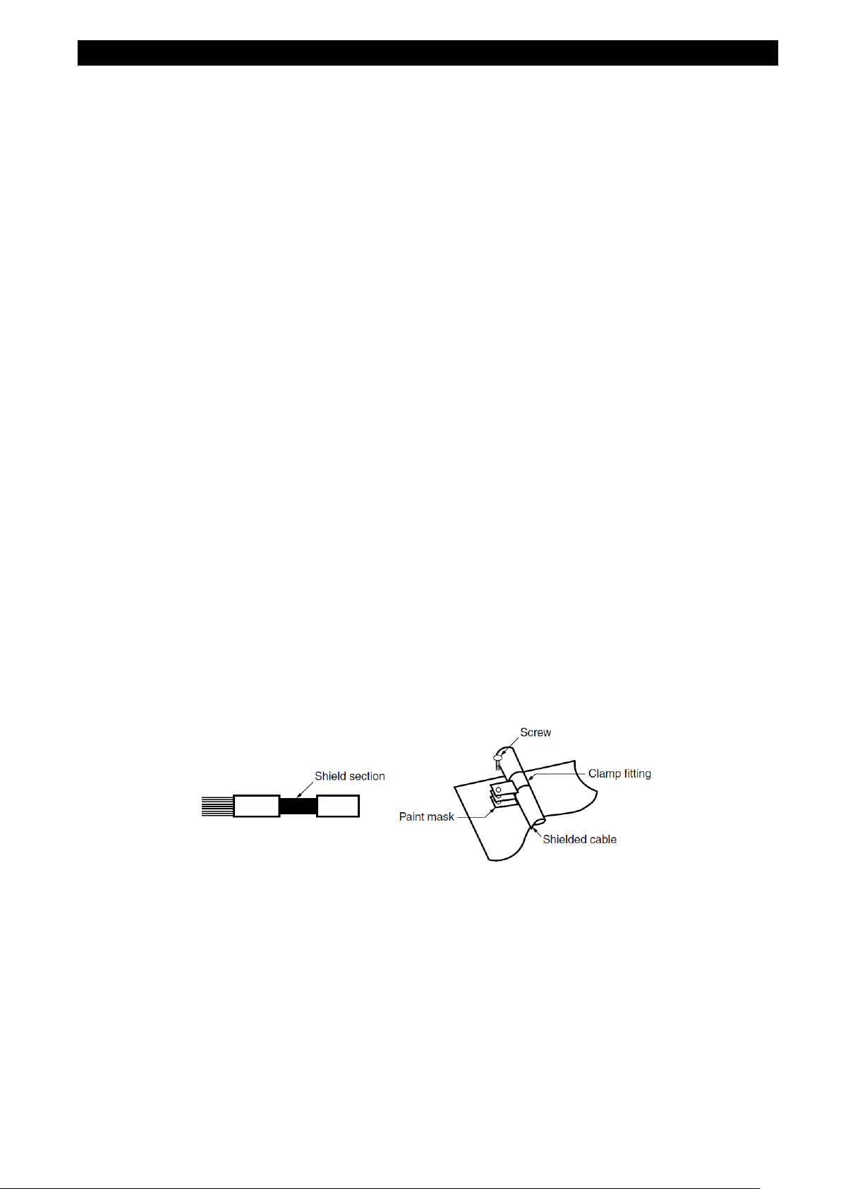
Wiring outside the cabinet must be conducted with shielded cables, and the cables must be fixed to the
panel with clamps. (Strip the covering of shielded cable by a portion of clamp installation and then mask
the grounding part of the panel and clamp so as not to be painted.)
9
Page 11

Table for measuring element code
Measuring element code
Measuring element name
A1
Current, 1-phase
A2
Current, 2-phase
A3
Current, 3-phase
AN
Current, N-phase
A
AVG
Current, average
DA1
Current demand, 1-phase
DA2
Current demand, 2-phase
DA3
Current demand, 3-phase
DAN
Current demand, N-phase
DA
AVG
Current demand, average
V12
Voltage, between 1-2 lines
V23
Voltage, between 2-3 lines
V31
Voltage, between 3-1 lines
V
AVG
(L-L)
Voltage, average, line to line
V1N
Voltage, 1N-phase
V2N
Voltage, 2N-phase
V3N
Voltage, 3N-phase
V
AVG
(L-N)
Voltage, average, line to neutral
W1
Active power, 1-phase
W2
Active power, 2-phase
W3
Active power, 3-phase
ΣW
Active power, total
var1
Reactive power, 1-phase
var2
Reactive power, 2-phase
var3
Reactive power, 3-phase
Σvar
Reactive power, total
VA1
Apparent power, 1-phase
VA2
Apparent power, 2-phase
VA3
Apparent power, 3-phase
ΣVA
Apparent power, total
PF1
Power factor, 1-phase
PF2
Power factor, 2-phase
PF3
Power factor, 3-phase
ΣPF
Power factor, total
Hz
Frequency
Wh
Active energy
varh
Reactive energy
VAh
Apparent energy
DW
Rolling demand active power
Dvar
Rolling demand reacti ve pow er
DVA
Rolling demand apparent power
HI
Harmonic current
HIN
Harmonic current, N-phase
HV
Harmonic voltage
THDi
Harmonic current total distortion ratio
THDv
Harmonic voltage total distortion ratio
Aunb
Current unbalance rate
Vunb
Voltage unbalance rate
DI
Digital input
DO
Digital output
The following table shows a list of measuring element codes used in the manual.
10
Page 12
1. Name and Function of Each Section
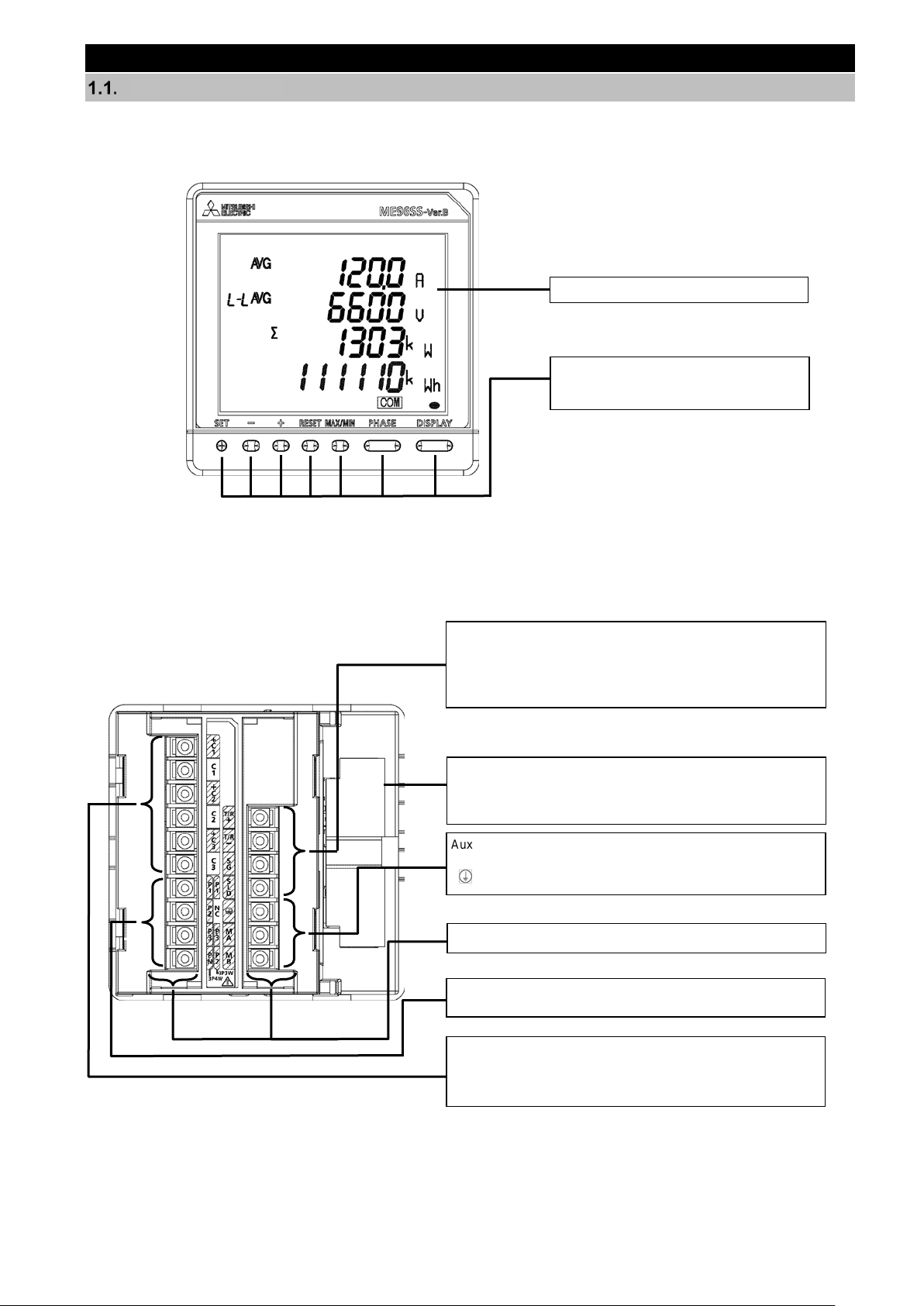
Name of Each Part
<The instrument>
■The front of the unit
LCD with backlight
Operation buttons
*For details, refer to 1.3 Function of
Operation Buttons.
■The back of the unit
MODBUS RTU communication terminals
T/R+: MODBUS RTU communication transmission terminal
T/R-: MODBUS RTU communication transmission terminal
SG: MODBUS RTU signal ground terminal
SLD: Shielded wire terminal (Ground resistance: 100 Ω or less)
Option cover
Remove the option cover to attach each optional plug-in
module. For the terminal names of optional plug-in modules,
refer to the next page.
Auxiliary power input terminals
MA, MB: Connect to an auxiliary power.
: Ground terminal (Ground resistance: 100 Ω or less)
Termi nal c overs
Voltage Input terminals
P1, P2, P3, PN (P1, NC, P3, P2): Circuit voltage is input.
Current Input terminals
+C1, C1: Input a circuit current.
+C2, C2: Input a circuit current.
+C3, C3: Input a circuit current.
11
Page 13
1. Name and Function of Each Section
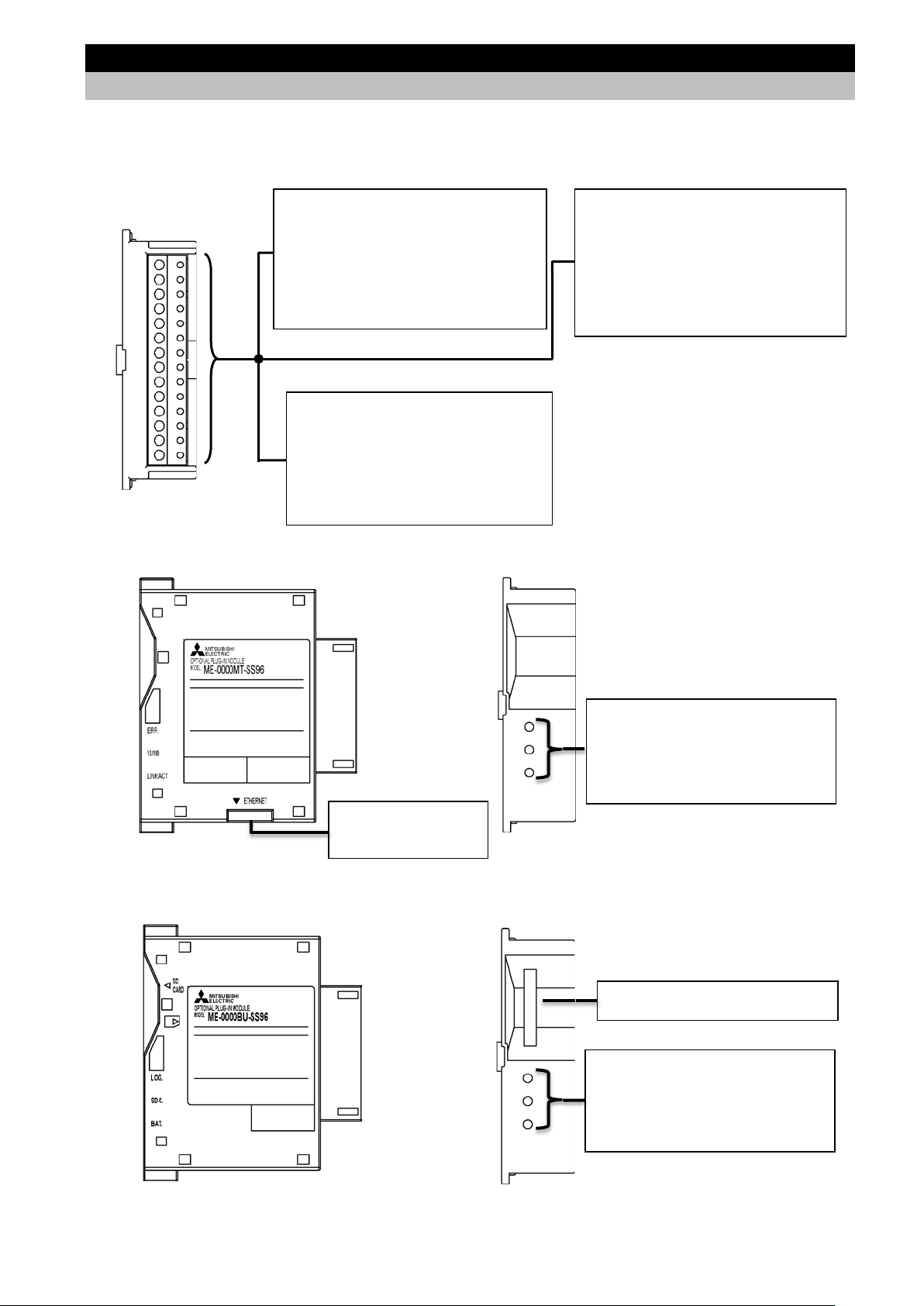
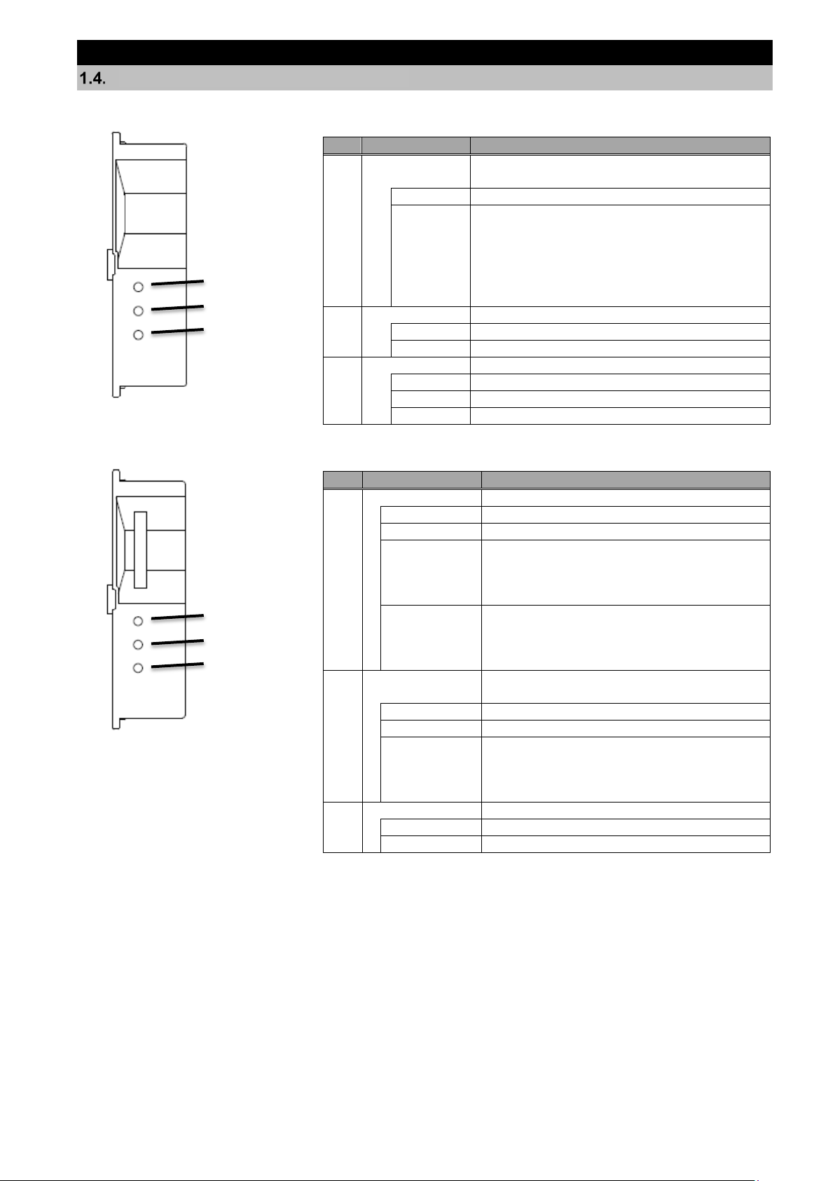
Input/Output terminals (ME-4210-SS96B)
1.1. Name of Each Part
<The optional plugs-in module>
■The back view (Model type: ME-4210-SS96B, ME-0040C-SS96, ME-0052-SS96)
CH1+, CH1-: Analog output terminal
CH2+, CH2-: Analog output terminal
CH3+, CH3-: Analog output terminal
CH4+, CH4-: Analog output terminal
C1A/A1, C1B/COM1: Pulse/Alarm output
C2A/A2, C2B/COM2: Pulse/Alarm output
DI+, DI-: Digital input terminal
Input/Output terminals (ME-0052-SS96)
DI1+, DI1-: Digital input terminal
DI2+, DI2-: Digital input terminal
DI3+, DI3-: Digital input terminal
DI4+, DI4-: Digital input terminal
DI5+, DI5-: Digital input terminal
DO1+, DO1-: Digital output terminal
DO2+, DO2-: Digital output terminal
■The side/back view ((Model type: ME-0000MT-SS96)
Input/Output terminals (ME-0040C-SS96)
DA: CC-Link communication terminal
DB: CC-Link communication terminal
DG: CC-Link communication terminal
SLD: Shielded wire terminal
FG: Ground terminal
(Ground resistance: 100 Ω or less)
DI1, DI2, DI3, DI4, DI COM: Digital input
terminal
10BASE-T/100BASE-TX
Connection connector
(RJ45)
■The side/back view (Model type:
LED indicators
(Refer to 1.4 LED display of optional
plug-in module.)
ERR. Red
10/100 Green
LINK/ACT Green
ME-0000BU-SS96)
Slot for SD memory card
LED indicators
(Refer to 1.4 LED display of optional
plug-in module.)
LOG. Red
SD C. Red
BAT. Red
12
Page 14
1. Name and Function of Each Section
Light up in the setting mode
Blink in the setting confirmation mode
Upper/lower limit alarm
status
CC-Link version
Hardware abnormality
Communication error
address*1
Error occurrence such
*1
*1. For details, refer to 6.5 Troubleshooting.
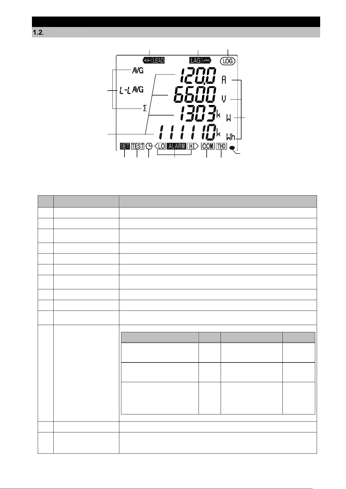
LCD Function
1 2
4
5
3
6
8
7
Note: The above display is an example for explanation.
9
10
11
12
13
No. Name of each part Function
1 LEAD status Light up on the reactive energy (imported lead)/ (exported lead) screen.
2 LAG status Light up on the reactive energy (imported lag)/ (exported lag) screen.
3 Built-in logging status Light up when the built-in logging function is operating
4 Digital element display Display measuring elements expressed in digital numbers
5 Digital display Display measured values in digital numbers
6 Unit Display the units of measured values
7 Setup status
8 Test mode status Light up in the test mode
9 Clock status Light up when the present time is set.
10
Blink when the upper/lower limit alarm is generating
Communication/
11
Option
logging status display
12 Harmonics Light up when harmonic is displayed
13 Metering status
Note 1: The blinking cycle is constant regardless of measuring input size.
Specification ON Blink OFF
CC-Link communication Normal
MODBUS RTU communication
MODBUS TCP communication
Option logging function Normal
Normal
mismatches
such as wrong
as setting abnormality,
SD memory card error,
or battery voltage drop
Blink when Imported active energy is measured *Note 1
*It appears on the imported active energy display screen only
13
Hardware
abnormality
Hardware
abnormality
Hardware
abnormality
Page 15
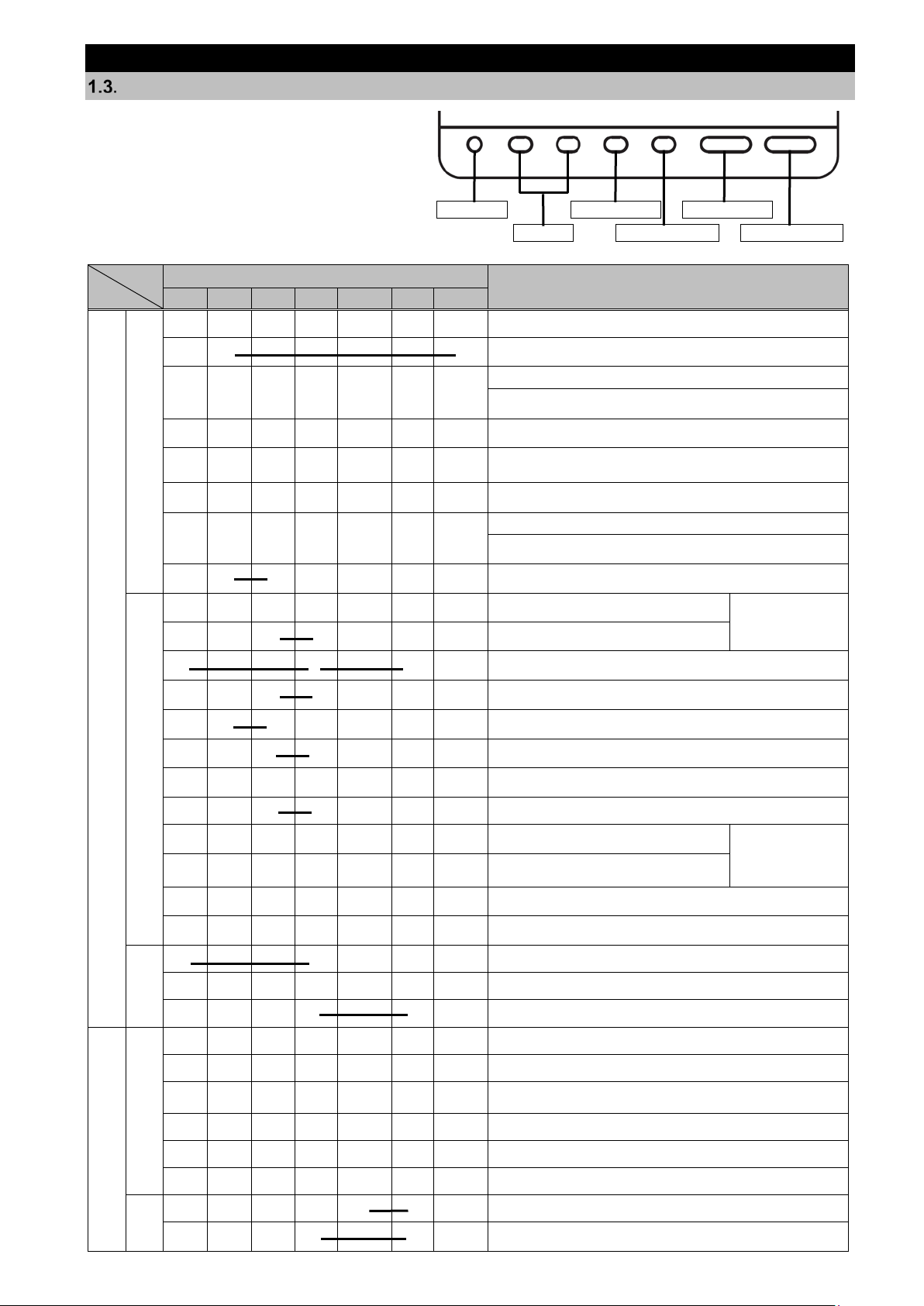
1. Name and Function of Each Section
Operation
Mode
HASE
Switch between the harmonic RMS value and distortion ratio.
(Available on the harmonics display screen)
Enter the cyclic display mode of measurement screen. Refer to
5.1.3.
Enter the cyclic display mode of phase. Refer to 5.1.3.
Switch between the harmonic RMS value and distortion ratio
screen in cyclic mode. (Available on the harmonics display)
Change the units of Wh, varh, and VAh or display the lowerdigit enlarged view. Refer to 5.1.9.
Alarm reset
Clear the Max/Min values displayed on
the screen.
Clear Max/Min values for every item in
every screen.
Reset Wh, varh, and VAh to zero.
All measured values are reset to zero simultaneously.
Reset periodic active energy to zero.
(The periodic active energy displayed on the screen only)
Set the rolling demand time period on the rolling demand
screen.
Clear the rolling demand peak value on the rolling demand
screen.
Reset operating time to zero.
(The operating time displayed on the screen only)
◎
Reset the alarm.
(For the item displayed on the screen)
They are available
cancellation.
Stop the backlight blinking caused by alarm.
(Available only when set to backlight blinking)
Release the latch for digital input at once on the digital input
screen.
○
○
Round up/down the setting value.
(Pressing for 1 second or more enables fast forward.)
Special
operation
Initialize to the factory default settings. (Available on the
CANCEL screen) Refer to 3.16.
DISPLAY
Function of Operation Buttons
The function of each operation button varies
depending on how to press the button.
<Meaning of marks>
○: Press, □: Press for 1 second or more, ◎: Press for 2 seconds or more, ―― : Press simultaneously
SET - + RESET MAX/MIN P
○
○ ○
○
Display switching
Button name
SET - + RESET MAX/MIN-PHASE
SET button RESET button Phase button
+/- button MAX/MIN button DISPLAY button
DISPLAY
Switch the measurement screen.
Switch the measurement screen in the reverse direction.
Switch phase display.
Function
○
○ ○
◎
◎
◎ ◎
Operating mode
◎
◎ ◎
◎ ◎ ◎
◎ ◎
Measured value clear/
◎ ◎
◎ ◎
◎
◎
○
◎
Enter/Exit the Max/Min value screen.
Switch the harmonic degree on the harmonics display screen.
They are available
on the Max/Min
value screen.
Reset CO
Reset all alarms at once.
(For every item in every screen)
equivalent to zero on the CO2 equivalent screen.
2
only when set to
manual alarm
○
◎
Mode switch
◎ ◎
◎
◎ ◎
○
Setting operation
Setting confirmation mode
Setting mode/
○
□
□
□
○
○
□ □
◎ ◎
Enter the setting mode.
Enter the setting confirmation mode.
Enter the password protection screen.
Determine the settings and then shift to the next settings.
Return to the previous setting item.
Skip the settings and return to the setting menu screen.
Reflect the setting change. (Available on the END screen)
Cancel the setting change. (Available on the CANCEL screen)
Restart the instrument. (Available on the CANCEL screen)
14
Page 16

1. Name and Function of Each Section
When you execute a function such as ‘Reset Max/Min value’ or ‘Reset Wh, varh, and
1.3. Function of Operation Buttons
Note: During backlight off mode, pressing any operation button first turns on the backlight. In addition, press ing any button
again enables the use of the functions in the above table.
VAh to zero’, past data is deleted. If you need to keep the data, record the data before
CAUTION
the reset operation.
When you execute ‘Restart the instrument’, the entire measurement function
(measurement display, communication) will stop for a few seconds.
15
Page 17
1. Name and Function of Each Section
No.
Name
Function
1
ERR. LED
Indicate the communication status of
ME-0000MT-SS96.
OFF
Normal
ON
The following MODBU S TCP communication
received such as function code for serial.
2
10/100 LED
Indicate transmission speed
ON
100 Mbps or unconnected
OFF
10 Mbps
3
LINK/ACT LED
Indicate the link status
ON
The link is established.
Blink
Blink when sending or receiving.
OFF
The link is not established.
No.
Name
Function
1
LOG. LED
Indicate the logging operation status
ON
Logging is operating.
OFF
Logging operation stops
Low-speed
0.5 sec: off)
The setting change of logging conditions has
High-speed
0.25 sec: off)
When the logging element pattern is LP00,
the setting file in the SD memory card is
Continue blinking until it turns to normal.
2
SD C. LED
Indicate the communication status of SD
memory card.
ON
Communicating
OFF
Communication stops
High-speed
0.25 sec: :off)
It is a SD memory card error
available capacity.
3)
BAT. LED
Indicate the battery voltage status.
OFF
Normal battery voltage
ON
Battery voltage drop
LED Display of Optional Plug-in Module
■LED (ME-0000MT-SS96)
1. ERR.
2. 10/100
3. LINK/ACT
errors occur:
・There is an abnormality in the MODBUS TCP
application protocol head part.
LED becomes off when normal messages are
・
■LED (ME-0000BU-SS96)
1. LOG.
2. SD C.
3. BAT.
blinking
(0.5 sec: on/
blinking
(0.25 sec: on/
blinking
(0.25 sec: on/
been completed.
Blink for 5 seconds.
abnormal.
Check that the SD memory card is not in
‘write protect’ status and that there is
16
Page 18
2. Each Mode Function
Operating
This is a normal operation mode to display each measured value in digital
automatically switches the display screen every 5 seconds, is available.
5 Operation
Setting
This is a mode where you can change the settings for measurement and output
Reset the settings to the factory default.
3 How to
Setting
This is a mode where you can confirm the setting of each item.
.
angle and voltage phase angle.
3.15 or 4
SET
+
-
Operating mode
Present value
display
Max/Min value
display
Setting mode
Setting
confirmation mode
Test mode
SET
SET
SET
SET
SET
RESET
End screen
CANCEL
screen
+
Save the
settings
Cancel the
settings
Press
for 2 seconds
simultaneously.
When you
select “End”
in the menu
When you select
“End”
in
the menu
Press for 2 seconds
ON
Blink
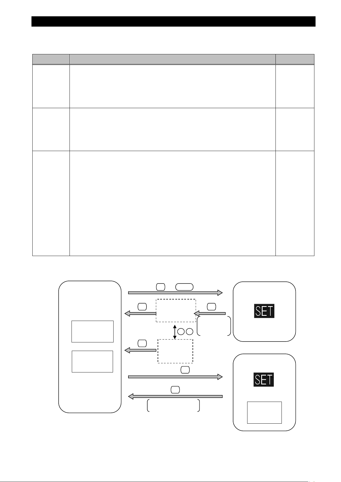
The instrument has the following operation modes.
When auxiliary power is supplied, the operating mode is first displayed.
Depending on the application, switch the operation mode to use.
Mode Description Reference
mode
mode
confirmation
mode
(Test mode)
numerical number. In the operating mode, there are ‘Present value di splay’ that
shows values at present and ‘Max/Min value display’ that shows the maximum
and minimum values in the past.
In addition, on each display screen, the cyclic display mode, which
functions.
In addition, on the CA NCEL screen, which is the scr een to cancel the setting
change, the following special operations are available.
・ Restart the instrument.
・
In this mode, you cannot change the setting. Therefore, it is possible to prevent
from accidentally changing the setting.
The mode also provides test function available at startup of systems
・ Communication Test: Without measurement (voltage/current) input, fixed
numerical data is returned.
・ Analog output adjus tment: Analog output adjustm ent is executed such as
zero adjustment or span adj us tm ent.
・ Output test: Without measurement (voltage/current) input, alarm/digital
output, analog output, or pulse output is executed.
・ Support function for checking input wiring:
When either a voltage input or current input is incorrectly wired,
the incorrect wiring p art is displ ayed on th e screen. In addition,
useful information is also displayed such as a current phase
Set up
How to Use
Test Mode
■Flow of each mode
17
Page 19
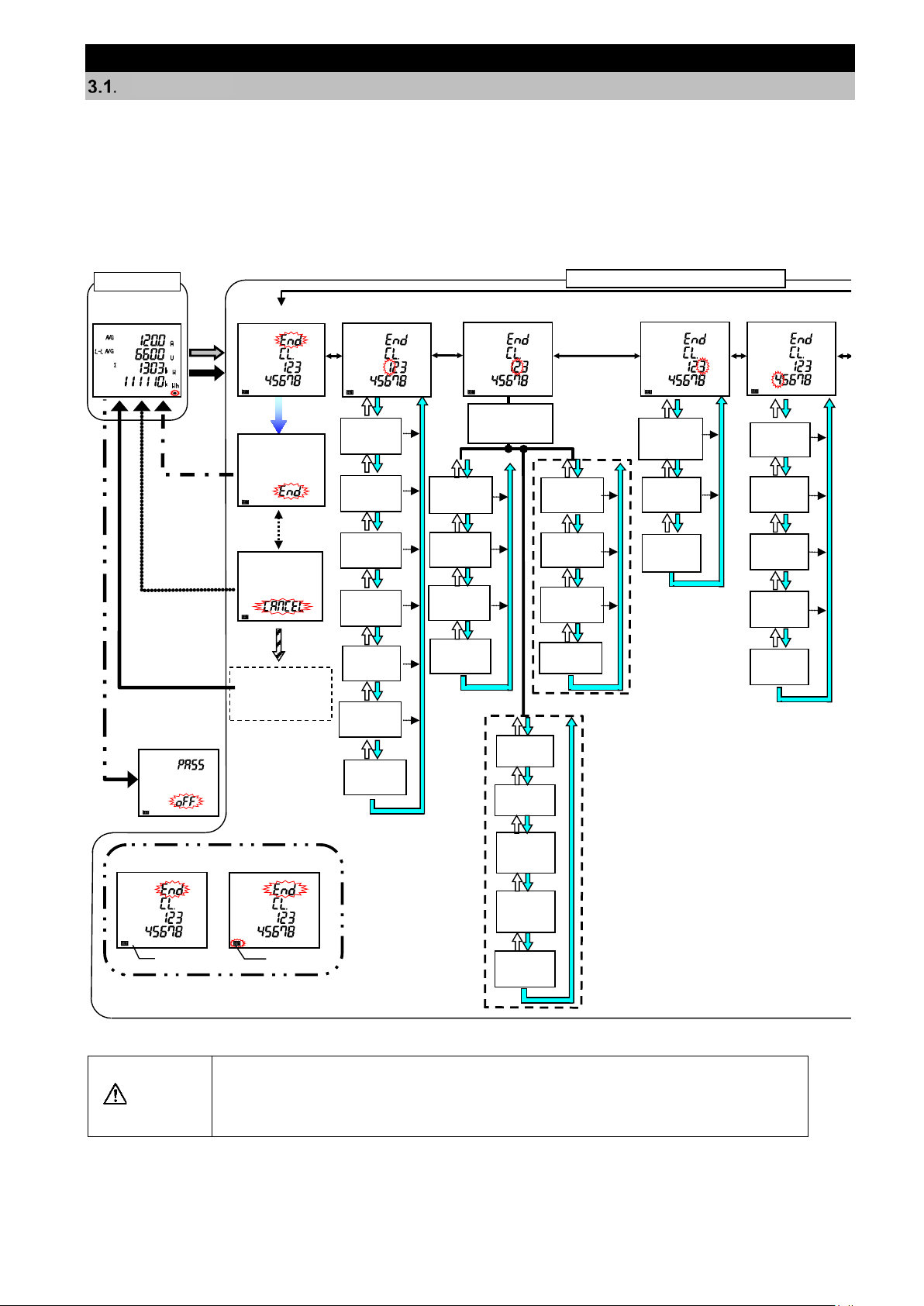
3. How to Set up
When you change a s etting, the related settin g items and measured data will be
Measurement
screen
Setting Menu
End
End
screen
CANCEL
screen
Automatic shift
Cancel the
settings
Save the
settings
Instrument restart
or
Factory default
settings
Operating Mode
*2
*1
Password
protection
screen
Harmonics
display
Active/
Reactive
energy
measurement
Frequency
Setting Menu 1
Setting Menu 2
Setting Menu 3
<When ME-0040C-SS96 is installed>
Communication
setting
selection
Model
display
Version
display
Backlight
brightness
Backlight
Auto off/
ON
Display
Update
time
Setting Menu
4
*1: If password protection is enabled, password
input is necessary to enter the setting mode
from the operating mode.
*2: In the s
etting confirmation mode, the screen
returns to the operating mode.
*3: This is not displayed in the setting mode.
Setting Menu or Setting Confirmation
Mode
MODBUS
TCP
IP address
MODBUS
TCP
Subnet mask
MODBUS
TCP
Default
gateway use
MODBUS
TCP
Default
gateway
MODBUS
TCP
Reset
<When ME-0000MT-SS96 is
installed>
Unbalance
d
ratio
display
Example of
Setting Mode
Example of Setting
Confirmation Mode
ON
Blink
CT current
VT/Direct
voltage
Display
pattern
Phase wire
system
MODBUS
RTU
Address
MODBUS
RTU
Parity
MODBUS
RTU
Stop bit
MODBUS
RTU
Baud rate
CC-Link
Station
number
CC-Link
Baud rate
CC-Link
Version
setting
CC-Link
Reset
Rolling
demand
time period
Demand
current
time period
Setting Flow
For measurement, you must set settings such as phase wire system, VT/Direct voltage, and CT primary current
in the setting mode.
From the operating mode, enter the setting mode and then set necessary items. Any items not set remain in the
factory default.
For normal use, set up the items in the setting menu 1 only. For details on the settings, refer to 3.2.
For details on the factory default settings, refer to 8.7.
CAUTION
For details on the initialization, refer to 3.16 Initialization of Related Items by
Changing a Setting.
initialized. Therefore, check that beforehand.
18
Page 20
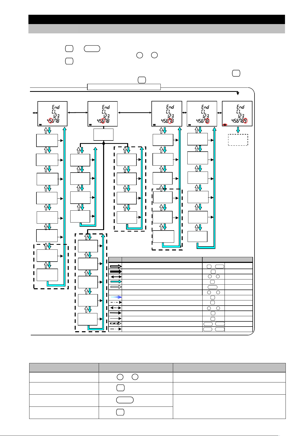
Analog
Output 4
Analog
Output 3
Analog
Output 2
Analog
Output 1
Contact
input
Reset method
Contact
input/output
Display
Rolling
demand
Time period
Rolling
demand
Display
Periodic
active energy
Display
CO2
Conversion
rate
CO2
Equivalent
display
Setting Confirmation
Menu 9
Setting Menu 5
Setting Menu 6
Setting Menu 7
Setting Menu 8
Pulse
output
*3
*3
<When ME-4210-SS96B
is installed>
<When ME-0052-SS96 is installed>
Setting menu or Setting Confirmation Mode
Detailed data
Logging
period
Logging
Item
pattern
Logging
Data clear
Logging ID
Option
selection
Mark
Action
Button operation
Enter the setting mode from the operating mode
+
Press
for 2 seconds
simultaneously
Enter the setting confirmation mode from the operating mode
Press for 2 seconds
Select the menu number to set up or select End
or
Press several times
Enter the setting screen. Shift to the next setting item
Pres
s
Return to the previous setting item
Press
Omitted
Select a se
t value.
or
Press several times.
Shift to the
End screen
Press
Save the settings and then return to the operating mode
Press
Select CANCEL
or
Press
Cancel the settings.
Press
Skip the current settings during setup
Press for 1 second
Reset the settings to the factory default.
+
Press for 2 seconds
Enter the password protection screen from the operating mode
+
Press for 2 seconds
Built-in
logging
Period
Built
-in
logging
Item pattern
Built-in
logging
Use
Built
-in
logging
Data clear
DISPLAY
RESET
+
-
SET
PHASE
RESET
SET
SET
SET
SET
+
-
SET
SET
PHASE
RESET
+
-
Upper/Lower
limit alarm
valu
e
Alarm
delay time
Alarm
reset
method
Backlight
blinking
for alarm
Motor starting
current
delay time
Upper/Lower
limit alarm
item
P
ulse/Alarm
output
function
Test Mode
Operating
time
Threshold
Operating
time
Count target
Operating
time
Display
IEC mode
settings
<When ME-0000BU-SS96
is installed>
Output
limit
Periodic
active energy
Switching
<When ME-4210-SS96B
is installed>
When the setting is determined, the screen
switches to the next setting item.
Return to the previous
setting item
Return to the setting menu
during setup
SET
+
-
SET
SET
RESET
+
-
SET
SET
DIS PLAY
SET
3. How to Set up
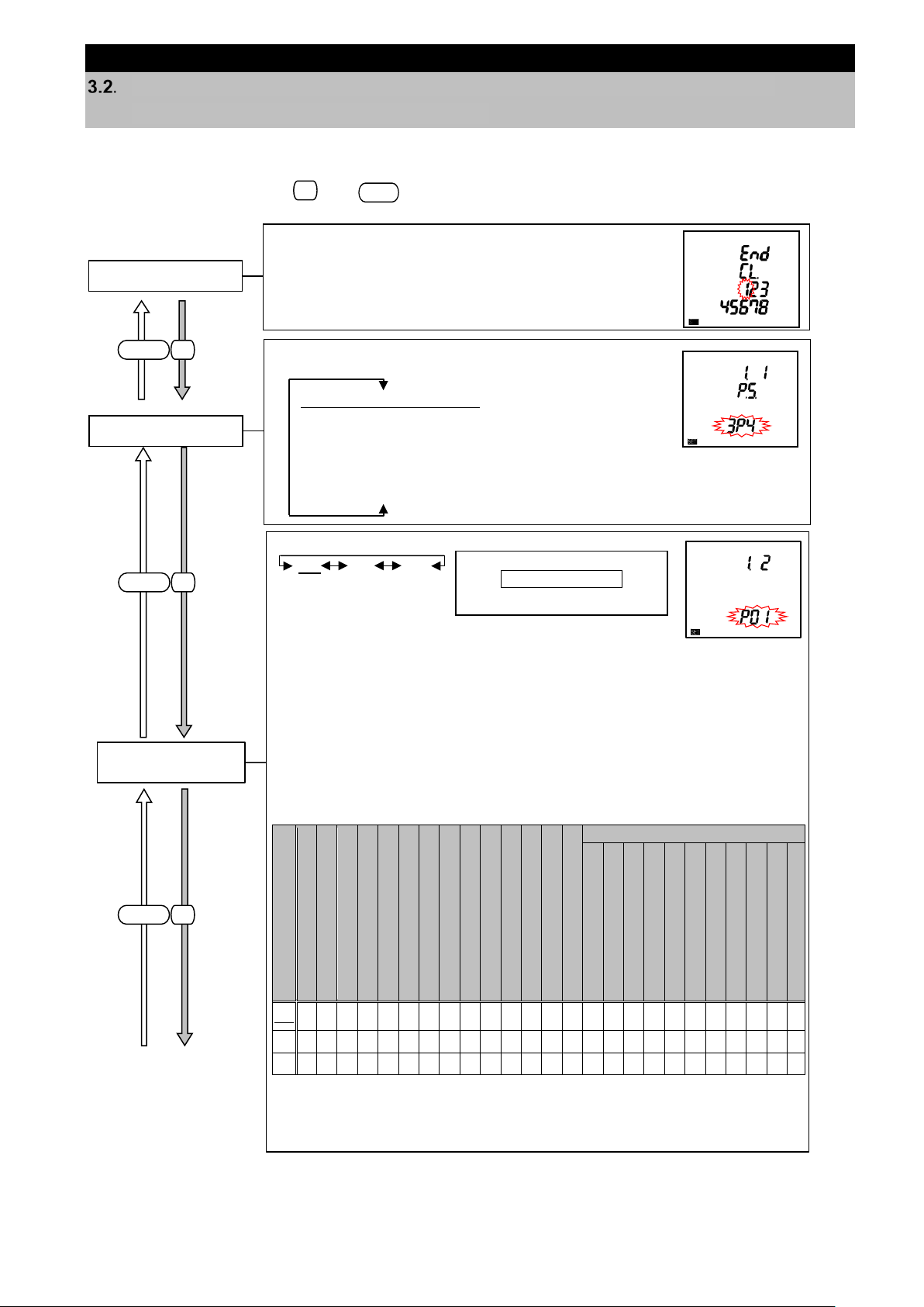
3.1. Setting Flow
<Setting Procedure>
① Press the and buttons simultaneously for 2 seconds to enter the setting mode.
② Select the setting menu number with the or button.
③ Press the button to determine the setting menu number.
④ Set each setting item. (Refer to 3.2 to 3.14.)
⑤ After completing all the settings, select End in the setting menu and then press the button.
⑥ When the End screen appears, press the button again.
■Basic operation for settings
The following table shows a list of basic operations for settings.
Function Operation Note
Select a setting
Determine a setting
Press or button
Press button
Press button
Press button for 1 second
19
Fast-forward by pressing for 1 second or more
The setting before return is enabled.
Page 21
SET
RESET
SET
DIS PLAY
SET
DIS PLAY
SET
DIS PLAY
Set the display pattern.
Current N
Current demand N
Voltage Active Power P
Reactive
Apparent
Frequency Active Energy (
Active Energy (Ex
Reactive
Apparent
Additional Screen *Note
Active Energy (
P00
Set the phase wire system
according to the measurement target circuit.
①Phase wire system
3P4: 3-phase 4-wire
3P3. 2CT: 3-phas e 3-wire(2CT)
3P3. 3CT: 3-phas e 3-wire(3CT)
1P3. 1N2: 1-phase 3-wire(1N2 display)
1P3. 1N3: 1-phase 3-wire(1N3 display)
1P2: 1-phase 2-wire
Note: The underlined
shows the
default setting.
(The same as below)
Select 1 in the setting menu number.
*Refer to the right figure.
Setting Menu
<When 1-phase 2-wire system is
P02 is not selectable.
3. How to Set up
Setting Menu 1: Basic Setup (Settings for Phase Wire System, Display Pattern,
VT/Direct Voltage, and CT Primary Current)
You will set the phase wire system, display pattern, VT/Direct voltage, CT primary current, and demand time
period.
In the operating mode, press and simultaneously for 2 seconds or more to enter the following
operation.
②Display Pattern
P01 P02 P00
set at ①Phase wire system.>
The following table shows measuring elements displayed on
each display pattern. The measuring elements displayed on P01
and P02 are the same. For P01, four elements are displayed in
one screen. For P02, each phase is displayed in one screen . For
details, refer to 6.1.
P00 is a special display pattern to freely set display items. For
details on the settings, refer to 3.18.
○:Displayable only by this setting
△:Other additional settings are necessary to display.
□:Select ‘P00’ and set up the display order and position.
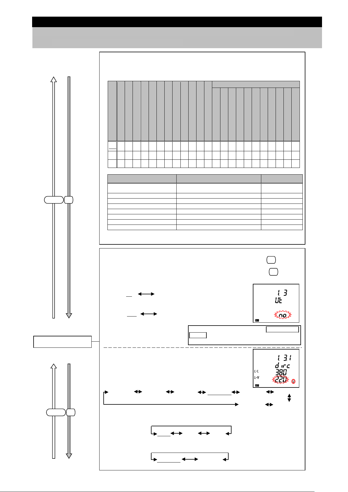
1) When set to 3-phase 4-wire system
-phase Current
-phase Current dema nd
Display Pattern
ower Factor
Power
Active Energy (Exported)
Reactive Energy (Special)
Apparent Energy
Energy
Power
Energy (Imported lag)
Imported)
ported)
Imported)
Periodic Active Energy
Rolling Demand
Harmonic Current/Voltage
Unbalance Rate
Digital Input/output status
Operating Time
CO
2
Equivalent
P01 ○ ○ ○ ○ ○ ○ ○ ○ ○ ○ ○ ○ ○ ○ ○ ○ ○ ○ △ △ △ △ △ △ △
P02 ○ ○ ○ ○ ○ ○ ○ ○ ○ ○ ○ ○ ○ ○ ○ ○ ○ ○ △ △ △ △ △ △ △
Continued to the next page.
□ □ □ □ □ □ □ □ □ □ □ □ □ □ △ △ △ △ △ △ △ △ △ △ △
20
Page 22
SET
DIS PLAY
Set the settings for VT.
・For direct measurement (without VT) ⇒ Select no, and then press .
Follow the settings of (1).
・For measurement with VT ⇒ Select yES and then press .
Follow the settings of (2).
1. When set to
3-phase 4
-wire system
2. When set to 3-phase 3 -wire/1-phase 2-wire system
Note. VT is Voltage Transformer.
(1) For direct measurement input (without VT)
(a) When set to 3-phase 4-wire system
(Phase voltage/Line voltage)
(b) When set to 3-phase 3-wire system (2CT, 3CT) /1-phase 2 -wire system
(Line voltage)
(c) When set to 1-phase 3-wire system (1N2, 1N3)
(Phase voltage/Line voltage)
③VT/Direct voltage
When you set 1-phase 3-wire at ①phase wire
system, direct measurement input only is
available. This setting will be skipped.
SET
SET
110 V 220 V 440 V
yES no
110/220 V 220/440 V
no yES
63.5/110 V 100/173 V 110/190 V 220/380 V 230/400 V 240/415 V
277/480 V 254/440 V
SET
DIS PLAY
Current Current demand Voltage Active Power Power Factor Reactive Power Apparent Power Frequency Active Energy (
Active Energy (Ex
Reactive Energy (Imported lag)
Apparent Energy
Additional Screen *Note
Active Energy (
Active Energy (
Reactive Energy (Special) Apparent Energy Period
Rolling Demand Harmonic Current/Voltage Unbalance Rate Digital
Operating Time C
P02
P00
Measuring element
of the additional screen
Active energy (Exporte d),
Reactive energy (Special)*
Setting menu 3 Active/Reactive energy
measurement
Harmonic current, Harmonic voltage
Setting menu 3 Harmonics display
3.6
Unbalance rate
Setting menu 3 Unbalance rate display
3.6
Periodic active energy
Setting menu 7 Periodic active energy display
3.12
Rolling demand
Setting menu 7 Rolling demand display
3.12
Digital input/output status
Setting menu 7 Digital input/output display
3.12
Operating time
Setting menu 8 Operating time display
3.13
CO2 equivalent
Setting menu 8 CO2 equivalent displ a y
3.13
3. How to Set up
3.2 Setting Menu 1: Basic Setup (Settings for Phase Wire System, Display Pattern,
VT/Direct Voltage, and CT Primary Current)
Continued from the previous page.
2)When set to other than 3-phase 4-wire system
*For 1-phase 2-wire system, P02 is not selectable.
Display Pattern
Imported)
○ ○ ○ ○ ○ ○ ○ ○ ○ ○ ○ ○ ○ ○ ○ ○ △ △ △ △ △ △ △
P01
○ ○ ○ ○ ○ ○ ○ ○ ○ ○ ○ ○ ○ ○ ○ ○ △ △ △ △ △ △ △
□ □ □ □ □ □ □ □ □ □ □ □ △ △ △ △ △ △ △ △ △ △ △
ported)
Imported)
Imported)
Note: The following settings are necessary to display the elements of the additional screens.
Setting item
ic Active Energy
Input/output Status
Reference
3.6
O
2
Equivalent
*To display the additional screens of active/reactive/apparent energy of P00, you must set
each item as display element.
21
Page 23
SET
DIS PLAY
Continued form the previous page.
(2) For measurement with VT
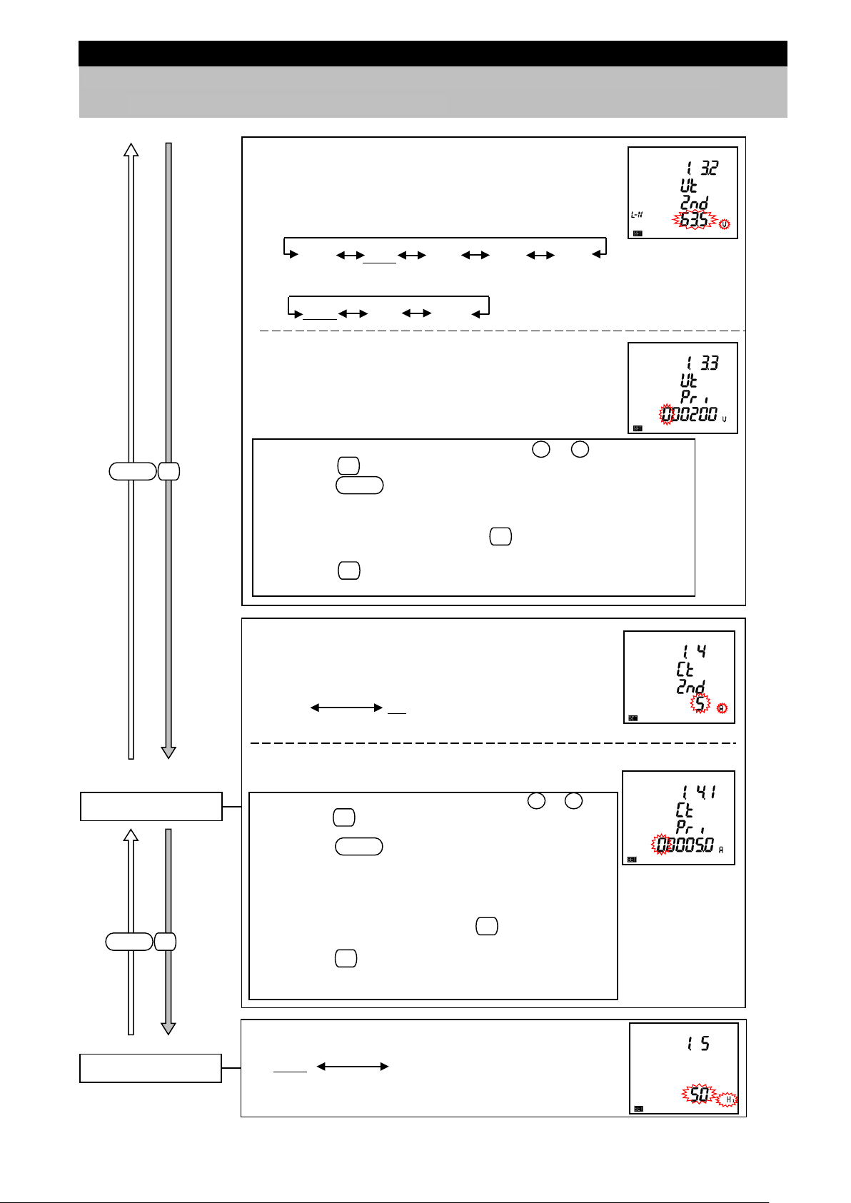
<Secondary voltage setting>
(a) When set to 3-phase 4-wire system (Phase voltage)
63.5 V 100 V 110 V 115 V 120 V
(b) When set to 3-phas e 3-wire (2CT, 3CT) /1-phase 2-wire system (Line voltage)
<Primary voltage setting>
The factory default settings:
・For 3-phase 4-wire system ⇒ 200 V (Phase voltage)
・For 3-phse 3-wire/1-phase 2-wire system ⇒ 10000 V
(Line voltage)
・From the upper digit, set the blinking digit with or .
・By pressing , move the setting item, blinking one, to a lower digit.
・By pressing
, move the setting item, blinking one, to an upper digit.
・The setting ranges from 60 V to 750000 V. The setting unit is V.
*If you set out of range, the error message (E05) will appear.
If the error message appears, press and then review the setting to
set it again.
・By pressing at the lowest digit, shift to the next setting item.
100 V 110 V 220 V
+
-
SET
DIS PLAY
SET
SET
SET
DIS PLAY
Set the settings for CT.
You will set the primary and secondary current of CT.
<Secondary current setting>
Note: CT is Current Transformer.
<Primary current setting>
The factory default setting: 5.0 A
④CT current
・From the upper digit, set the blinking digit with or .
・By pressing , move the setting item, blinking one, to a
lower digit.
・By pressing , move the setting item, blinking one, to
an upper digit.
・The setting ranges from 1.0 A to 30000.0 A.
The setting unit is A.
*If you set out of range, the error message (E05) will appear.
If the error message appea
rs, press and t
hen review the
setting to set it again.
・By pressing at the lowest digit, shift to the next setting
item.
1 A 5 A
+
-
DIS PLAY
SET
SET
SET
Set the frequency.
⑤Frequency
50 Hz 60 Hz
3. How to Set up
3.2 Setting Menu 1: Basic Setup (Settings for Phase Wire System, Display Pattern,
VT/Direct Voltage, and CT Primary Current)
22
Page 24
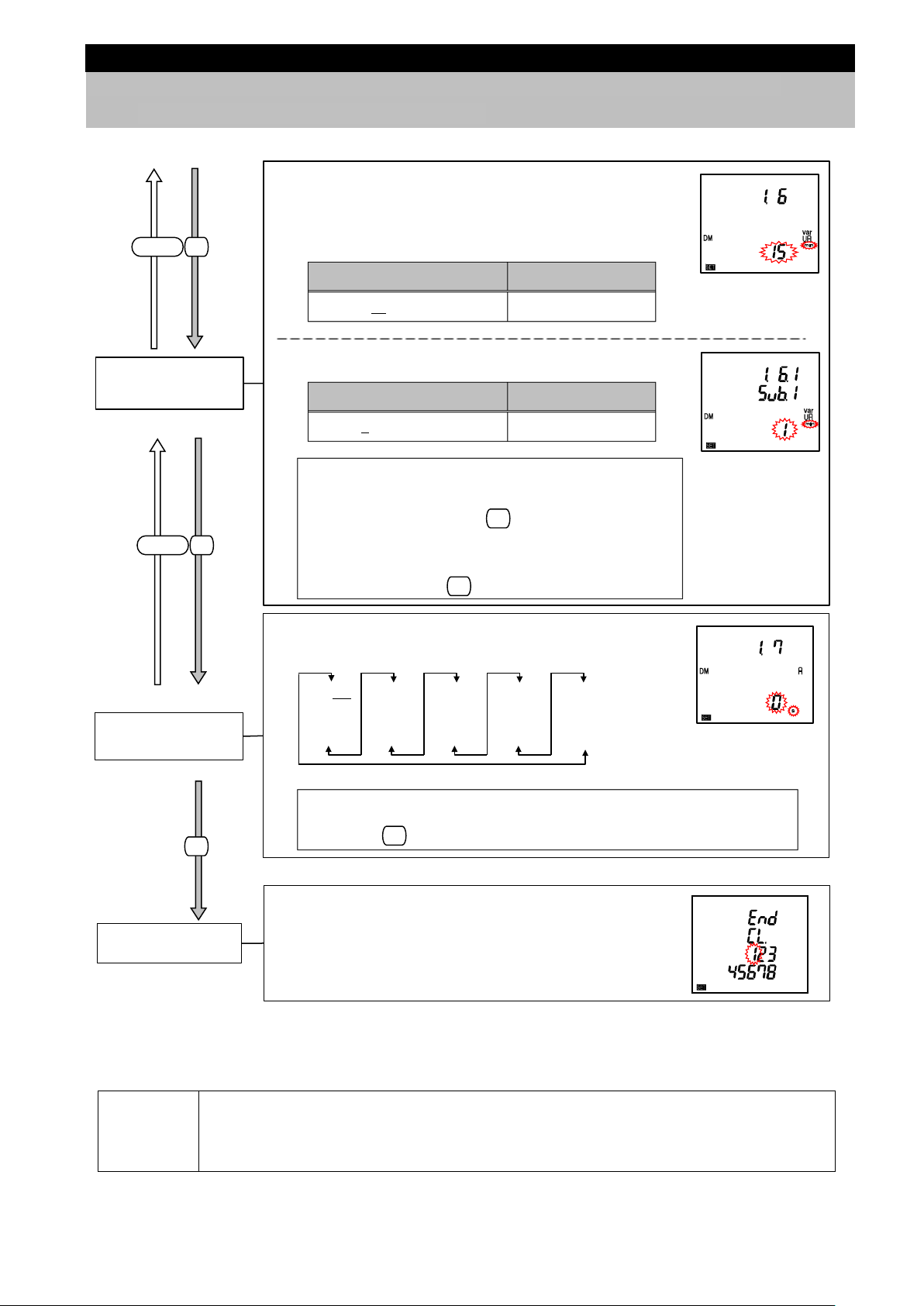
If you change a s etting in the setting menu 1 , the m aximum and minimum values of the
SET
SET
SET
DIS PLAY
SET
DIS PLAY
SET
SET
3. How to Set up
3.2 Setting Menu 1: Basic Setup (Settings for Phase Wire System, Display Pattern,
VT/Direct Voltage, and CT Primary Current)
⑥Rolling demand
time period
⑦Current demand
time period
Set the interval time period for rolling demand.
*For details on the rolling demand, refer to 5.2.7.
(1) Interval time period
Setting range Setting step
1 to 15 to 60(min) 1 min
(2) Subinterval time period
Setting range Setting step
1 to 60(min) 1 min
・If you set the interval time period to a value that is not
divisible by the subinterval time period, the error (E05) will
appear.
If the error appears, press and review the setting to
set it again.
・Even when you set the rolling demand to ‘oFF (Not
display)’, this screen appears. If rolling demand is not
necessary, just press .
Set the current demand time period.
For details on the current demand time period, refer to 5.1.13.
0 s
10 s
20 s
30 s
Note: Even when you set a display pattern that does not display current
40 s
50 s
1 min
2 min
demand, this screen appears. If current demand is not necessary, just
press .
3 min
4 min
5 min
6 min
7 min
8 min
9 min
10 min
15 min
20 min
25 min
30 min
According to 3.1 Setting Flow,
complete the settings or shift to other setting menu.
Setting Menu
If you set the settings only in the setting menu 1 to use, move to 5 Operation.
If you use an additional function, set it in the setting menu 2 to 8.
related measuring e lements will be reset. However, a ctive/reac tive/appar ent ene rgy value
Note
will not be reset.
For details, refer to 3.16 Initialization of Related Items by Changing a Setting.
23
Page 25
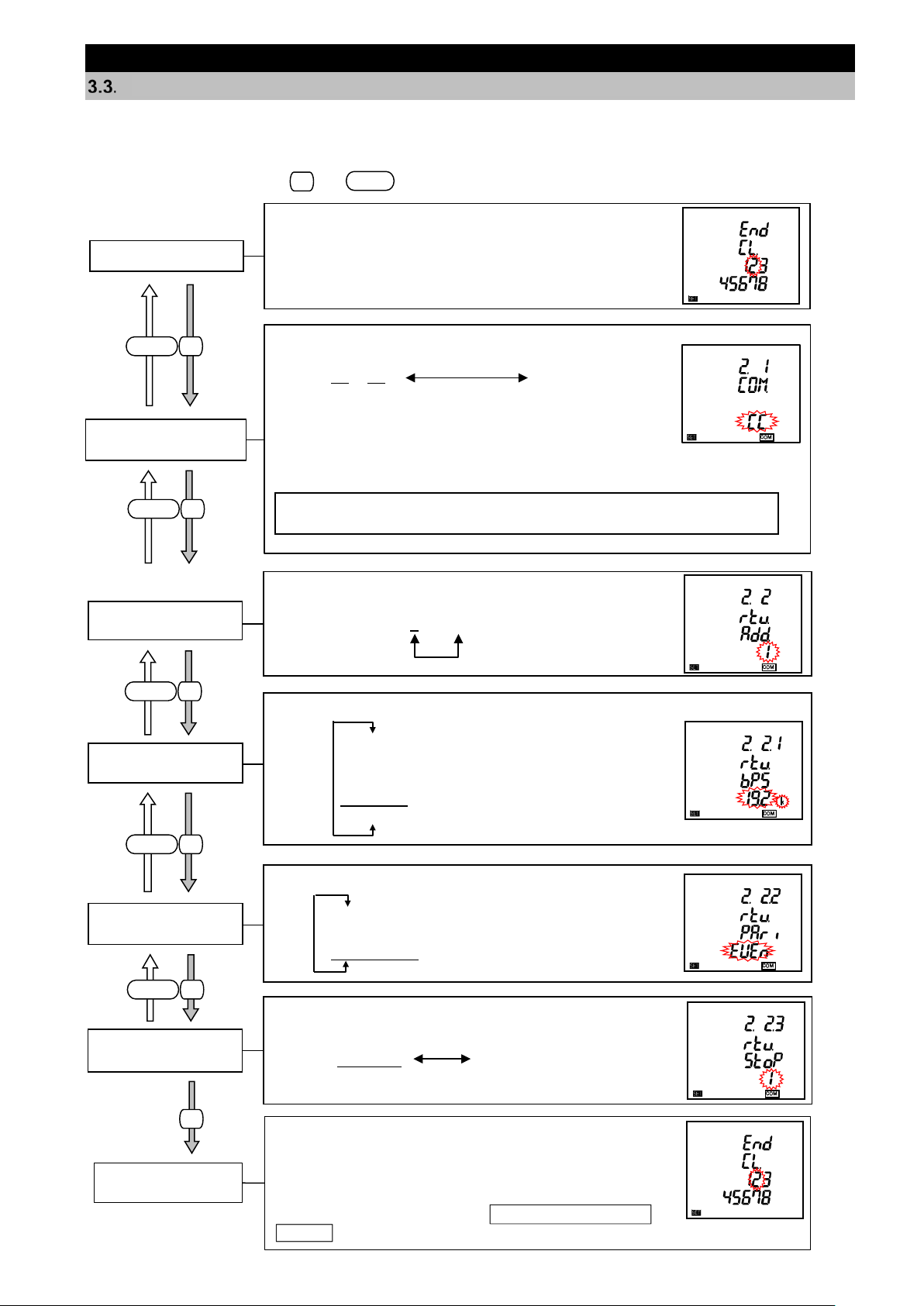
SET
RESET
Set the parity of MO DBUS RTU communication.
③MODBUS RTU
Parity
non
odd
even (EVEn)
Set the baud rate of MODBUS RTU communication.
②MODBUS RTU
Baud rate
2400 bps
4800 bps
9600 bps
19.2 kbps
38.4 kbp
s
Set the address of MODBUS RTU communication.
Settable address: 1 to 255
①MODBUS RTU
Address
Set the stop bit of MODBUS RTU communication.
④MODBUS RTU
Stop bit
Stop bit 1 Stop bit 2
Select 2 in the setting menu number.
*Refer to the right figure.
Setting Menu
Select option (CC-Link or MODBUS TCP communication)
SET
DIS PLAY
Note: When ME-0040C-SS96 or ME-0000MT-SS96 of optional plug-in module
is not installed, this setting is skipped.
SET
DIS PLAY
SET
DIS PLAY
SET
DIS PLAY
SET
DIS PLAY
SET
3. How to Set up
Setting Menu 2: Communication Settings (MODBUS RTU Communication Settings)
<The installation conditions for optional plug-in module>
No installation
In the operating mode, press and simultaneously for 2 seconds or more to enter the following
operation.
①Communication
setting selection (1)
or MODBUS RTU communication.
CC or tcP rtu
(Option) (MODBUS RTU communication)
The explanation here is about the MODBUS RTU communication
settings.
For the CC-Link communication settings, refer to 3.4.
For the MODBUS TCP communication settings, refer to 3.5.
According to 3.1 Setting Flow,
complete the settings or shift to other setting menu.
Setting Menu
In addition, if you need to set the settings for CC-Link or
MODBUS TCP communication, select the setting menu 2 again
and then select ‘CC’ or ‘Mb.rtu’ at ①Communication setting
selection.
24
Page 26
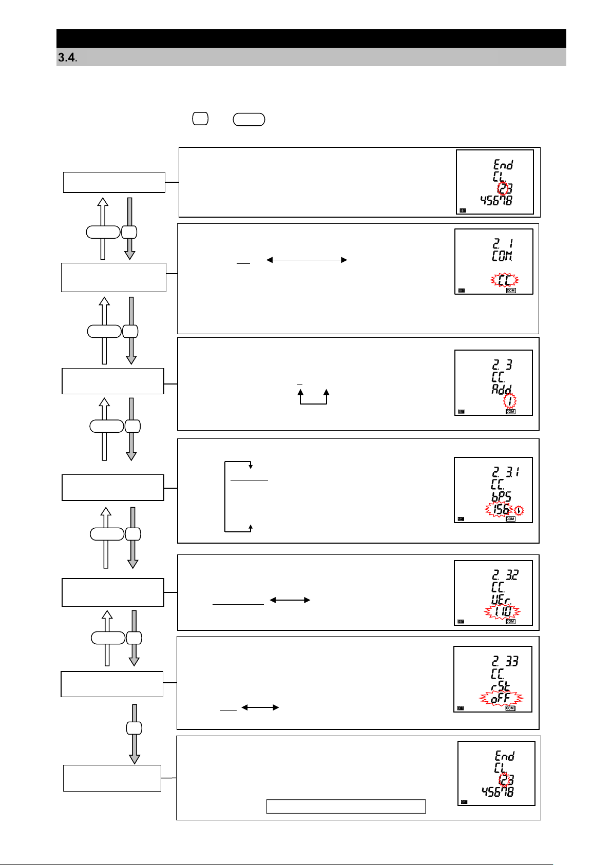
SET
RESET
Select 2 in the setting menu number.
*Refer to the right figure.
Setting Menu
SET
DIS PLAY
SET
DIS PLAY
SET
DIS PLAY
SET
DIS PLAY
SET
DIS PLAY
SET
Set the station number of CC-Link communication.
Settable station number: 1 to 64
②CC-Link
Station number
Set the baud rate of CC-Link communication.
③CC-Link
Baud rate
156 kbps
625 kbps
2.5 Mbps
5 Mbps
10 Mbps
Set the version of CC-Link communication.
④CC-Link
Version setting
Version 1.10 Version 2.00
According to
If you have changed a setting related to CC-Link
communication, set to ‘on.’
*If you do not set to ‘on’, the changed setting will not be
enabled.
⑤Communication
reset
oFF on
3. How to Set up
Setting Menu 2: Communication Settings (CC-Link Communication Settings)
<The installation conditions for optional plug-in module>
ME-0040C-SS96 installati o n
In the operating mode, press and simultaneously for 2 seconds or more to enter the following
operation.
①Communication
setting selection
Select CC-Link communication or MODBUS RTU
communication.
CC rtu
(CC-Link communication) (MODBUS RTU communication)
The explanation here is about CC-Link communication settings.
For the MODBUS RTU communication settings, refer to 3.3.
Setting Menu
complete the settings or shift to other setting menu.
In addition, if you need to set the settings for MODBUS
RTU communication, select the setting menu 2 again and
select ‘Mb. rtu’ at ①Communication setting selection.
3.1 Setting Flow,
25
Page 27
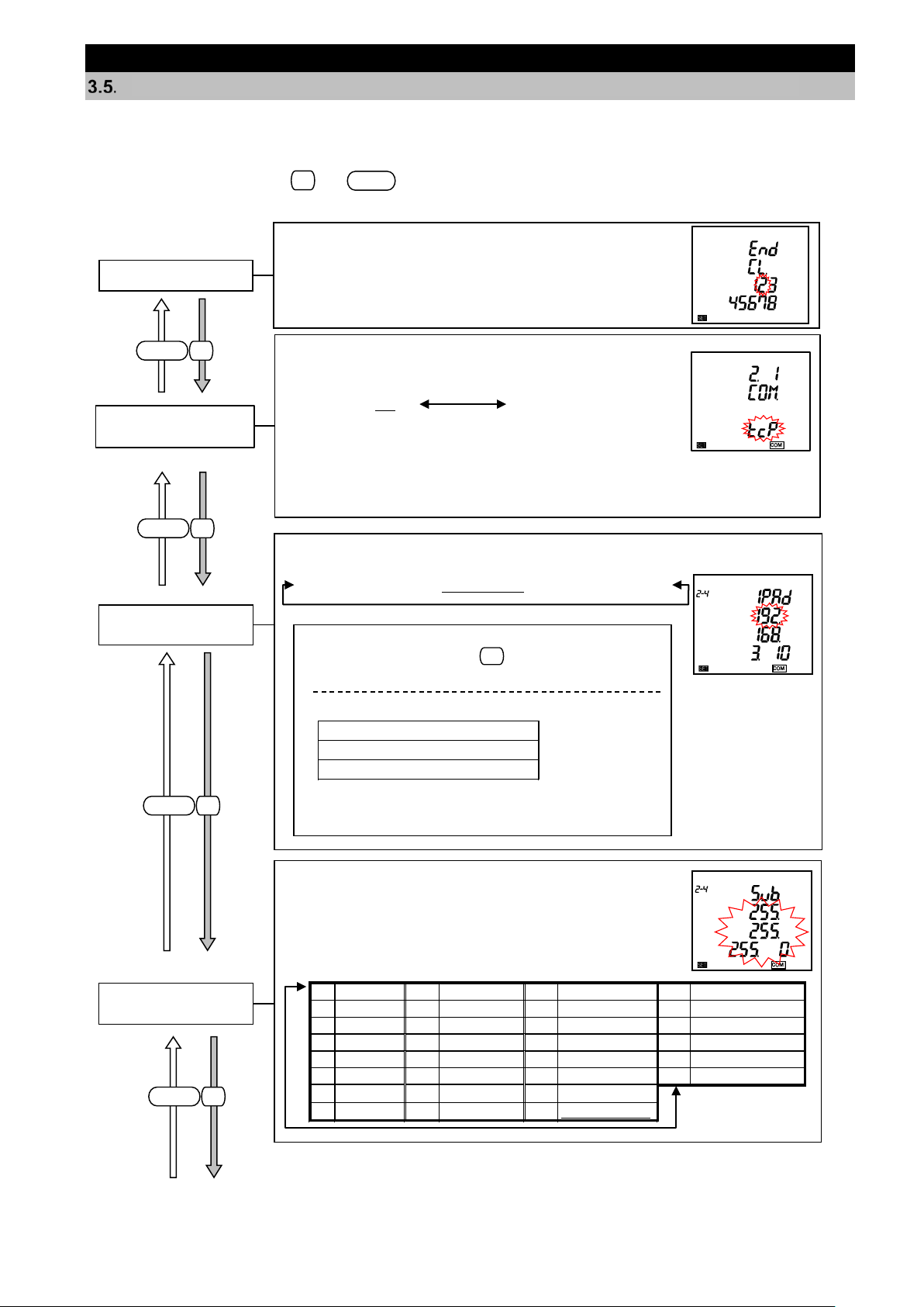
SET
RESET
Select 2 in the setting menu number.
*Refer to the right figure.
Setting Menu
SET
DIS PLAY
SET
DIS PLAY
SET
DIS PLAY
SET
DIS PLAY
Set the IP address of MODBUS TCP communication.
②MODBUS TCP
IP address
*If you set an invalid address, the error (E05) will appear.
If the error appears, press and review the setting to
set it again.
[The setting range of IP address]
1.0.0.0 to 126.255.255.255
128.0.0.0 to 191.255.255.255
192.0.0.0 to 223.255.255.255
However, the following IP addresses are impossible to s et
:
・0.0.0.0
・xxx.xxx.xxx.255 (xxx is any number.)
SET
000.000.000.000 to 192.168.3.10 to 255.255.255.255
Set the subnet mask of MOCBUS TCP communication.
Select a subnet mask setting from the following 30
types in the table.
(1)
128.0.0.0
(9)
255.128.0.0
(17)
255.255.128.0
(25)
255.255.255.128
(2)
192.0.0.0
(10)
255.192.0.0
(18)
255.255.192.0
(26)
255.255.255.192
(3)
224.0.0.0
(11)
255.224.0.0
(19)
255.255.224.0
(27)
255.255.255.224
(4)
240.0.0.0
(12)
255.240.0.0
(20)
255.255.240.0
(28)
255.255.255.240
(5)
248.0.0.0
(13)
255.248.0.0
(21)
255.255.248.0
(29)
255.255.255.248
(6)
252.0.0.0
(14)
255.252.0.0
(22)
255.255.252.0
(30)
255.255.255.252
(7)
254.0.0.0
(15)
255.254.0.0
(23)
255.255.254.0
(8)
255.0.0.0
(16)
255.255.0.0
(24)
255.255.255.0
③MODBUS TCP
Subnet mask
3. How to Set up
Setting Menu 2: Communication Settings (MODBUS TCP Communication Settings)
<The installation conditions for optional plug-in module>
ME-0000MT-SS96 install ati on
In the operating mode, press and simultaneously for 2 seconds or more to enter the following
operation.
①Communication
setting selection
Select MODBUS TCP communication or MODBUS RTU
communication.
(MODBUSTCP
communication)
The explanation here is about MODBUS TCP communication settings.
For the MODBUS RTU communication settings, refer to 3.3.
tcP rtu
(MODBUS RTU
communication)
26
Page 28
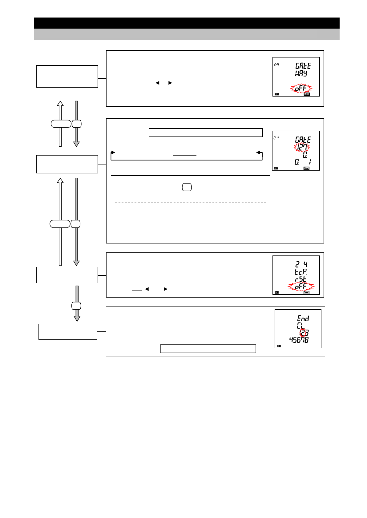
SET
SET
DIS PLAY
SET
DIS PLAY
Set whether default gate wa y exists.
If there is default gateway on the Ethernet , set to ‘on’
to communicate with other net work .
oFF on
④MODBUS TCP
Default gateway
use
Set the address of default gateway.
If you set ④MODBUS TCP Default gateway use to
“oFF”, this screen will not be displayed.
⑤MODBUS TCP
Default gateway
*If you set an invalid address, t he error (E05) will appear.
If the error appears, press and review the setting to set it
again.
The following default gateway addresses are impossible to set:
・0.0.0.0
・xxx.xxx.xxx.255 (xxx is any number.)
000.000.000.000 to 127.0.0.1 to 255.255.255.255
SET
If you have changed a setting related to MODBUS TCP
communication, set to ‘on.’
*If you do not set to
“on
”, the changed setting will not be enabled.
⑥Communication
reset
oFF on
According to
3. How to Set up
3.5. Setting Menu 2: Communication Settings (MODBUS TCP Communication Settings)
Setting Menu
3.1 Setting Flow,
complete the settings or shift to other setting menu.
In addition, if you need to set the settings for MODBUS
RTU communication, select the setting menu 2 again and
select ‘Mb. rtu’ at ①Communication setting selection.
27
Page 29
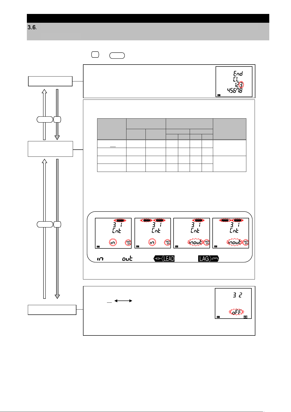
SET
RESET
SET
DIS PLAY
Active/Reactive
measurement
Set the display combination of active energy and reactive energy
Active energy
(Wh)
Reactive energy
(varh)
Reactive
method
Imported
Exported
lag
lead
lag
lead
Select 3 in the setting menu number.
*Refer to the right figure.
Setting Menu
Set the harmonic display.
When you set to ‘on (Display)’, harmonic measured valu es are displayed on
the additional screen of display pattern.
②Harmonics display
on oFF
(D
isplay)
(Not display)
Combination Ⅰ
Combination Ⅱ
Combination
Combination Ⅳ
SET
DIS PLAY
3. How to Set up
Setting Menu 3: Display Settings (Settings for Active/Reactive Energy and Harmonic
Measurement)
This section describes how to set the special measurement of active/reactive energy and harmonic display.
In the operating mode, press and simultaneously for 2 seconds or more to enter the following
operation.
(imported/exported, lag/lead) and the measurement method of reactive
energy.
Combination
(Setting)
Imported Exported
energy
measurement
①
energy
Ⅰ
Ⅱ
Ⅲ
Ⅳ
Note: For details on how to measure reactive energy, refer to 5.1.11.
Combination Ⅰ, Ⅱ ⇒ They are suitable for measuring systems without a
○
○ ○ ○
○ ○ ○ ○
○ ○ ○ ○ ○ ○
private power generator or measuring reactive
power of capacitor load where power factor is
Combination Ⅲ, Ⅳ ⇒ They are suitable for measuring systems with a
<Display exapmles>
Imported
When ‘Wh’ or ‘varh’ is selected in the display pattern of P00, it is displayed.
around zero generally.
private power generator.
Exported
○
varh (lead)
2 quadrant
measurement
4 quadrant
measurement
Ⅲ
varh (lag)
28
Page 30

Even when you select a display pattern that does not display active/reactive power or
2 quadrant/4 quadrant
SET
SET
DIS PLAY
3. How to Set up
3.6 Setting Menu 3: Display Settings (Settings for Active/Reactive Energy and Harmonic
Measurement)
③Unbalance rate
display
Set whether to display the unbalance rate.
on oFF
(Display) (Not dis play)
When you set to ‘on (Display)’, the voltage/current unbalance rate
can be displayed on the additional screen of display pattern.
Note: For 1-phase 2-wire system,
this setting is skipped.
Setting Menu
Note
According to 3.1 Setting Flow,
complete the settings or shift to other setting menu.
active/reactive energy, the setting items of ⑥ Active/Reactive energy measurement are
displayed because the symbol can be displayed as appropriate for
measurement of reactive power/power factor according to the settings of ⑥Active/Reactive
energy measurement.
29
Page 31

SET
RESET
SET
DIS PLAY
SET
DIS PLAY
SET
SET
DIS PLAY
SET
DIS PLAY
SET
DIS PLAY
Select
4 in the setting menu number.
*Refer to the right figure.
Setting Menu
It is possible to change the setting of display update time of
measured values. If the switch tim ing is too quick ly for you
to read the display value, set to 1 second.
*The default setting is 0.5 second.
0.5 second 1 second
⑤Display update
time
It is possible to select a backlight setting
from ‘Auto’ or ‘HoLd’.
④Backlight
Auto off/ON
Auto HoLd
<When the backlight is set to ‘Auto’>
No button operation for 5 m inutes → OFF
Button operation during off *Note → ON
for 5 minutes
Note: During OFF mode, when you operate
any button,
the backlight
lights up
and the display rem ains as it is.
When you press any button again,
the display
switches.
(
Auto off)
(ON)
It is possible to adjust the backlight brightness.
③Backlight
brightness
1 2 3 4 5
Dark Bright
You can check the product version.
*This is for display only and not possible
to change the settings.
②Version display
You can c heck the m odel. T his is for display only and not pos sible t o chan ge
the settings. Refer to the following table for the corresponding model.
(1) Second line
Model
ME96SSHB-MB
(2) Fourth line
Model name for optional plug-in module
Blank
ME-4210-SS96B
ME-0040C-SS96
ME-0052-SS96
ME-0000MT-SS96 *1
ME-0000BU-SS96
①Model displa y
*1 When “E90xx” appears, a
MODBUS TCP
communication error is
occurring.
According to
3. How to Set up
Setting Menu 4: LCD Settings (Settings for Model Display, Version Display, Backlight,
and Display Update Time)
This section describes how to check the model and set the back light and display update time. These settings
are not necessary for normal use.
In the operating mode, press and simultaneously for 2 seconds or more to enter the following
operation.
Setting Menu
3.1 Setting Flow,
complete the settings or shift to other setting menu.
30
Page 32

SET
RESET
SET
DIS PLAY
SET
DIS PLAY
Set a measuring element of upper/lower limit alarm item 1.
This setting enables upper/lower limit monitoring of a meas ured va lu e.
(1) When set to 3-phase 4-wire system
(2) When set to other than 3-phase 4-wire system
①Upper/Lower
limit alarm item 1
Note1.The m
easuring
elements no
t included in the
display pattern
you set can be
selected.
*1. It is not displayed for 1-phase 2-wire system.
Display for selection
of "A upper limit"
var upper limit
var lower limit
Dvar (Predict) upper limit
Dvar (Present) uppe r limit
Dvar (Last) upper limit
DVA (Predict) upper limit
DVA (Present) upper limit t
DVA (Last) upper limit
PF upper limit
PF lower limit
Hz upper limit
Hz lower limit
HI total upper limit
HIN total upper limit
THDV upper limit
Aunb upper limit
Vunb upper limit
non
A upper limit
A lower limit
AN upper limit
DA upper limit
DA lower limit
DAN upper limit
V (L-N) upper limit
V (L-N) lower limit
V (L-L) upper limit
V (L-L) lower limit
W upper limit
W lower limit
DW (Predict)
upper limit
DW (Present)
upper limit
DW (Last)
upper limit
non
A upper limit
A lower limit
DA upper limit
DA lower limit
V upper limit
V lower limit
W upper limit
W lower limit
DW (Predict)
upper limit
DW (Present)
upper limit
DW (Last)
upper limit
var upper limit
var lower limit
Dvar (Predict) upper limit
Dvar (Present) uppe r limit
Dvar (Last) upper limit
DVA (Predict) upper limit
DVA (Present) upper limit t
DVA (Last) upper limit
PF upper limit
PF lower limit
Hz upper limit
Hz lower limit
HI total upper limit
THDV upper limit
Aunb upper limit *1
Vunb upper limi t *1
Display for
selection of "non”
Select 5 in the setting menu number.
*Refer to the right figure.
Setting Menu
3. How to Set up
Setting Menu 5: Pulse/Alarm Settings (Settings for Upper/Lower Limit Alarm, Motor
Starting Current Mask Function, and Pulse Output)
This section describes how to set the upper/lower limit alarm, backlight blinking during alarm, motor starting
current, pulse output, and alarm output.
In the operating mode, press and simultaneously for 2 seconds or more to enter the following
operation.
For details about each function, refer to the following:
・Upper/lower limit alarm → See 5.2.1 to 5.2.3.
・Motor starting current → See 5.2.16.
31
Page 33

SET
DIS PLAY
SET
DIS PLAY
SET
DIS PLAY
Set the alarm value of each of upper/lower limit alarm item 2 to 4.
The setting method is the same as ②Upper/Lower limit alarm value 1.
④Upper/Lower limit
alarm value 2 to 4
Set a measuring element of each of upper/lower limit alarm item 2 to 4.
The item you have already selected is not available repeatedly.
The setting method is the same as ①Upper/Lower limit alarm item 1.
③Upper/Lower limit
alarm item 2 to 4
Set the alarm delay time if you want to prevent an alarm
caused by momentary overload or noise.
If you set this setting, an alarm will occur only when the
upper/lower limit alarm value is ex ceeded and the situatio n
continues for a period of alarm delay time.
⑤Alarm delay time
0 s
5 s
10 s
20 s
30 s
40 s
50 s
1 min
2 min
3 min
4 min
5 min
Note: When ①Upper/Lower limit alarm item 1
and ③Upper/Lower limit alarm item 2 to 4
are all set to “non”, this setting is skipped.
②
Setting
Step *
A, AN, DA, DAN upper limit
5 to 100 to 120 (%)
1%
A, DA lower limit
3 to 10 to 95 (%)
1%
V (L-N), V (L-L) upper limit
25 to 110 to 135 (%)
1%
V (L-N), V (L-L) lower limit
20 to 70 to 95 (%)
1%
W, var upper limit
-95 to 100 to 120 (%)
1%
W, var lower limit
-120 to 3 to 95 (%)
1%
DW, Dvar, DVA upper limit
5 to 100 to 120 (%)
1%
PF upper limit
-0.05 to 1 to 0.05
0.05
PF lower limit
-0.05 to -0.5 to 0.05
0.05
Hz upper limit
45 to 65 (Hz)
1Hz
Hz lower limit
45 to 65 (Hz)
1Hz
HI total upper limit
1 to 35 to 120 (%)
1%
HIN total upper limit
1 to 35 to 120 (%)
1%
THDV upper limit
0.5 to 3.5 to 20.0 (%)
0.5%
Aunb upper limit
1 to 30 to 99 (%)
1%
Vunb upper limit
1 to 3 to 99 (%)
1%
SET
DIS PLAY
3. How to Set up
3.8 Setting Menu 5: Pulse/Alarm Settings (Settings for Upper/Lower Limit Alarm, Motor
Starting Current Mask Function, and Pulse Output)
Upper/Lower limit
alarm value 1
Set the alarm value of upper/lower limit alarm item 1.
The following table shows the setting range.
Measuring element Setting range
*Note: W, var, DW, Dvar, and DVA show the percentage ratio of a standard value.
For details on how to calculate the standard value, refer to 6.2 .
A, AN, DA, DAN, HI total RMS value, and HI
percentage ratio of the CT primary current setting.
V shows the percentage ratio of the VT primary voltage (or direct voltage).
*For 1-phase 3-wire system, V shows the percentage ratio of the phase
voltage. For 12-phase or 31-phase, alarm monitoring is executed based on
twice the set upper/lower limit alarm value.
total RMS value show the
N
32
Page 34

SET
DIS PLAY
SET
DIS PLAY
SET
DIS PLAY
For motor current monitoring, this setting enables to
prevent unnecessary
maximum value update and alarm generating caused by motor starting
current.
・When this setting is not necessary ⇒ Select ‘oFF
’ and
then press
to move to the next setting item.
・When this setting is necessary ⇒ Select ‘on’ and then press
to move to (1) below.
(1) Motor starting current threshold
Set the threshold to detect motor starting current.
Setting range
Setting step
*
Note
3 to 5 to 120 (%)
1%
*Note: This is the percentage ratio of the CT primary
current setting.
(2) Motor starting current delay time
During the delay time after motor starting current is
detected, neither a maximum value update nor an
alarm is generated.
⑧Motor starting
current delay time
oFF on
1 s
3 s
5 s
10 s
15 s
20 s
30 s
45 s
4 min
5 min
SET
SET
SET
DIS PLAY
1 min
1.5 min
2 min
3 min
It is possible to blink the backlight for alarm.
⑦Backlight blinking
for alarm
o
FF on
(Not blink) (Blink)
Note: When ①
Upper/Lower
limit alarm item 1 and ③Up
per/Lower
limit
alarm item 2 to 4 are all set to “non”, this setting is skipped.
3. How to Set up
3.8 Setting Menu 5: Pulse/Alarm Settings (Settings for Upper/Lower Limit Alarm, Motor
Starting Current Mask Function, and Pulse Output)
⑥Alarm reset method
Set the reset method to cancel an alarm.
Reset method
(Settings)
Automatic
(Auto)
(For details, refer to 5.2.1 to 5.2.2.)
When alarm-generating conditions
disappear, the alarm is automatically
reset.
Even if alarm-generating conditions
Manual
(HoLd)
Note: When ①Upper/Lower limit alarm item 1 and ③Upper/Lower limit alarm
item 2 to 4 are all set to ‘non’, this setting is skipped.
disappear, the alarm is retained. To
cancel the alarm, you must execute
button operation.
Description
33
Page 35

SET
DIS PLAY
output function 1
Set the output item of pulse output 1.
When ME-4210-SS96B (optional plug-in module) is not
installed or when ⑨Pulse/Alarm output function 1 is not
set to pulse output, this screen is not displayed.
Setting item
Display
A B C
Active energy (Imported)
OFF
Active energy (Exported)
OFF
Reactive energy (Imported lag)
Reactive energy (Imported lead)
Reactive energy (Exported lag)
Reactive energy (Exported lead)
Apparent energy
OFF
Periodic active energy 1
OFF
Periodic active energy 2
OFF
Periodic active energy 3
OFF
non (No output)
OFF
OFF
⑩Pulse output 1
Output item
Note: According to the
selected item, the
segment in the left
table blinks.
A
B
C
Set the pulse unit of pulse output 1.
The pulse unit is selected from the following table
according to full-load power.
When ME-4210
-SS96
B (optional plug-in module) is not
installed or when ⑨Pulse/Alarm output function 1 is not
set to pulse output, this screen is not displayed.
*1: For 3-phase 4-wire system, the VT primary voltage and direct voltage are calculated
using phase voltage.
*2: For 1-phase 3-wire system, the VT primary voltage is calculated using phase voltage.
*3: For the direct voltage setting
, direct voltage is used for the calculation instead of VT
primary voltage.
Full-load power [kW]
Settable pulse unit
Below 10
1
0.1
0.01
0.001
kWh/pulse
10 or more and below 100
10
1
0.1
0.01
100 or more and below 1000
100
10 1 0.1
1000 or more and below 10000
1
0.1
0.01
0.001
MWh/pulse
10000 or more and b elow 100000
10 1 0.1
0.01
100000 or more
100
10 1 0.1
Note1: When ⑩Pulse output 1 Output item is set to ‘non’, this setting is skipped.
Note2: The factory default setting is the minimum value of settable pulse unit.
Note3: For reactive power, read ‘kW’ and ‘kWh’ of the above table as ‘kvar’ and ‘kvarh’
respectively.
Note4: For apparent power, read ‘kW’ and ‘kWh’ of the above table as ‘kVA’ and ‘kVAh’
respectively.
⑪Pulse output 1
Pulse unit
α: 1 1-phase 2-wire
2
1-phase 3
-wire
3
3-phase 2-wire
3
3-phase 4-wire
Full-load power [kW] =
α× (VT primary voltage) × (CT primary voltage)
1000
SET
DIS PLAY
SET
DIS PLAY
3. How to Set up
3.8 Setting Menu 5: Pulse/Alarm Settings (Settings for Upper/Lower Limit Alarm, Motor
Starting Current Mask Function, and Pulse Output)
⑨Pulse/Alarm
Set the function of pulse/alarm output 1.
When ME-4210-SS96B (optional plug-in module) is not
installed, this screen is not displayed.
For alarm items at selecting alarm output, refer to 5.2.4.
PULSE AL
(Pulse output) (Alarm output)
34
Page 36

According to
Pulse/Alarm
output function 2
Set the output item of pulse output 2.
It is possible to set the same item as pulse output 1.
When ME-4210-SS96B (optional plug-in module) is not
installed or when ⑫Pulse/Alarm output function 2 is not set
to pulse output, this screen is not displayed.
The setting method is the same as ⑩Pulse output 1
Output item.
The factory default setting: Reactive energy (Im ported lag)
⑬Pulse output 2
Output item
SET
DIS PLAY
SET
DIS PLAY
SET
DIS PLAY
SET
Set the pulse unit of pulse output 2.
When ME-4210-SS96B (optional plug-in module) is not
installed or when ⑫Pulse/Alarm output function 2 is not set
to pulse output, this screen is not displayed.
The setting method is the same as ⑪Pulse output
1
Output unit.
The factory default setting: The minimum value of settable pulse unit
Note: When ⑬
Pulse
output 2 Output item is set to “non”, this setting is sk ipped .
⑭Pulse output 2
Pulse unit
Set the pulse width of output pulse
according to the input pulse conditions of receiver side.
When ME-4210
-SS96B (optional plug
-in module) is not
installed or when ⑨Pulse/Alarm output function 1 or ⑫
Pulse/Alarm output function 2 is not set to pulse output, this
screen is not displayed.
Note
When the pulse width is set to 0.500 s or 1.000 s, if the pulse unit is
set to the minimum value, the pulse output cannot track under large
load conditions and it can result in a decrease in the pulse output
number.
⑮Pulse width
0.125 s 0.500 s 1.000 s
3. How to Set up
3.8 Setting Menu 5: Pulse/Alarm Settings (Settings for Upper/Lower Limit Alarm, Motor
Starting Current Mask Function, and Pulse Output)
⑫
Set the function of pulse/alarm output 2.
When ME-4210-SS96B (optional plug-in module) is not
installed, this screen is not displayed.
For alarm items at selecting alarm output, refer to 5.2.4.
AL PULSE
(Alarm output) (Pulse output)
Setting Menu
complete the settings or shift to other setting menu.
3.1 Setting Flow,
35
Page 37

SET
RESET
Select 6 in the setting menu number.
*Refer to the right figure.
Setting Menu
Clear the logging data that this instrument stores.
SET
DIS PLAY
SET
DIS PLAY
Note: When ME-4210-SS96B or ME-0000BU-SS96 of optional plug-in module
is not installed, this setting is skipped.
SET
DIS PLAY
SET
DIS PLAY
3. How to Set up
Setting Menu 6: Built-in Logging Settings
You will set the built-in logging.
In the operating mode, press and simultaneously for 2 seconds or more to enter the following
operation.
①Option selection
Select option (analog output or optional logging) or built-in logging.
Ao or Log.PLUG Log.buiLt
(Option) (Built-in logging)
The explanation here is about the built-in logg ing settings.
For the analog output settings, refer to 3.10.
For the optional logging settings, refer to 3.11.
②Built-in logging
Data clear
(Not clear) (Clear)
When you select ‘yES’ at the above setting, the screen
appears again to confirm the determination.
(Not clear) (Clear)
Set whether to use the built-in logging function.
③Built-in logging
use
(Not use) (Use)
Select a logging item pattern to set data for built-in logging.
Settable pattern:
④Built-in logging
Item pattern
When setting to LP00, you can select any logging item.
For details on LP00, refer to the following document.
∙Electronic Multi-Measuring Instrument ME Series MODBUS Interface
specifications LSPM-0075
The logging item patterns of LP01 and LP02 are defined as the following table.
Continued to the next page.
no yES
no yES
oFF on
LP00 LP01 LP02
36
Page 38

(1) Phase wire system: 3-phase 4-wire
SET
DIS PLAY
3. How to Set up
3.9 Setting Menu 6: Built-in Logging Settings
Logging item pattern
Logging measuring data
(Integrated value data) 1
Logging measuring data
(Integrated value data) 2
Logging measuring data
(Integrated value data) 3
Logging measuring data
(Integrated value data) 4
Logging measuring data
(Integrated value data) 5
Logging measuring data
(Data other than integrated value) 1
Logging measuring data
(Data other than integrated value) 2
Logging measuring data
(Data other than integrated value) 3
Logging measuring data
(Data other than integrated value) 4
Logging measuring data
(Data other than integrated value) 5
Logging measuring data
(Data other than integrated value) 6
Logging measuring data
(Data other than integrated value) 7
Logging measuring data
(Data other than integrated value) 8
Logging measuring data
(Data other than integrated value) 9
Logging measuring data
(Data other than integrated value) 10
Logging measuring data
(Data other than integrated value) 11
Logging measuring data
(Data other than integrated value) 12
Logging measuring data
(Data other than integrated value) 13
Logging measuring data
(Data other than integrated value) 14
Logging measuring data
(Data other than integrated value) 15
(2) Phase wire system: 3-phase 3-wire (2CT)/ 3-phase 3-wire (3CT)/ 1-phase 3-wire
Logging item pattern
Logging measuring data
(Integrated value data) 1
Logging measuring data
(Integrated value data) 2
Logging measuring data
(Integrated value data) 3
Logging measuring data
(Integrated value data) 4
Logging measuring data
(Integrated value data) 5
Logging measuring data
(Data other than integrated value) 1
Logging measuring data
(Data other than integrated value) 2
Logging measuring data
(Data other than integrated value) 3
Logging measuring data
(Data other than integrated value) 4
Logging measuring data
(Data other than integrated value) 5
Logging measuring data
(Data other than integrated value) 6
Logging measuring data
(Data other than integrated value) 7
Logging measuring data
(Data other than integrated value) 8
Logging measuring data
(Data other than integrated value) 9
Logging measuring data
(Data other than integrated value) 10
Logging measuring data
(Data other than integrated value) 11
Logging measuring data
(Data other than integrated value) 12
Logging measuring data
(Data other than integrated value) 13
Logging measuring data
(Data other than integrated value) 14
Logging measuring data
(Data other than integrated value) 15
LP01 LP02
Wh (Imported) Wh (Imported)
Wh (Exported) Wh (Exported)
varh (Imported lag) varh (Imported lag)
varh (Imported lead) varh (Imported lead)
VAh VAh
ΣW ΣW
ΣPF ΣPF
Hz Hz
Σvar A
ΣVA V
A
A1
AVG
V
(L-L) A2
AVG
DW (La st) A3
Dvar (Last) AN
DVA (Last) V12
DW (Peak) V23
Dvar (Peak) V31
DVA (Peak) V1N
HI1 (total) V2N
THD
V3N
v1N
LP01 LP02
Wh (Imported)
Wh (Exported) Wh (Exported)
varh (Imported lag) varh (Imported lag)
varh (Imported lead) varh (Imported lead)
VAh VAh
ΣW ΣW
ΣPF ΣPF
Hz Hz
Σvar A
ΣVA V
A1
A
AVG
V
(L-L) A2
AVG
DW (La st) A3
Dvar (Last) DVA (Last) V12
DW (Peak) V23
Dvar (Peak) V31
DVA (Peak) -
HI1 (total) -
-
THD
v12
Wh (Imported)
37
AVG
AVG
AVG
(L-L)
AVG
(L-L)
Page 39

Set the logging period of the built-in loggi ng.
SET
DIS PLAY
SET
DIS PLAY
3. How to Set up
3.9 Setting Menu 6: Built-in Logging Settings
Continued from the previous page.
(3) Phase wire system: 1-phase 2-wire
Logging item pattern
Logging measuring data
(Integrated value data) 1
Logging measuring data
(Integrated value data) 2
Logging measuring data
(Integrated value data) 3
Logging measuring data
(Integrated value data) 4
Logging measuring data
(Integrated value data) 5
Logging measuring data
(Data other than integrated value) 1
Logging measuring data
(Data other than integrated value) 2
Logging measuring data
(Data other than integrated value) 3
Logging measuring data
(Data other than integrated value) 4
Logging measuring data
(Data other than integrated value) 5
Logging measuring data
(Data other than integrated value) 6
Logging measuring data
(Data other than integrated value) 7
Logging measuring data
(Data other than integrated value) 8
Logging measuring data
(Data other than integrated value) 9
Logging measuring data
(Data other than integrated value) 10
Logging measuring data
(Data other than integrated value) 11
Logging measuring data
(Data other than integrated value) 12
Logging measuring data
(Data other than integrated value) 13
Logging measuring data
(Data other than integrated value) 14
Logging measuring data
(Data other than integrated value) 15
LP01 LP02
Wh (Imported) Wh (Imported)
Wh (Exported) Wh (Exported)
varh (Imported lag) varh (Imported lag)
varh (Imported lead) varh (Imported lead)
VAh VAh
ΣW ΣW
ΣPF ΣPF
Hz Hz
Σvar ΣVA -
A1
A
AVG
(L-L) -
V
AVG
DW (La st) Dvar (Last) DVA (Last) V12
DW (Peak) -
Dvar (Peak) DVA (Peak) -
HI1 (total) -
THD
-
v12
⑤Built-in data
logging period
Setting Menu
According to 3.1 Setting Flow,
complete the settings or shift to other setting menu.
15 min 30 min 60 min
38
Page 40

SET
RESET
SET
DIS PLAY
SET
DIS PLAY
Select 6 in the setting menu number.
*Refer to the right figure.
Setting Menu
3-phase 4-wire system
non
V12
VA∑
PF1
Continued to the next page.
Analog output CH1
output item
Note1: The same measuring item can be set for each CH.
N
Note3: Channels set to ‘non’ have the minimum output (4mA). In addition, it proceeds
N
Note5: VA is output with a scaling of 0 to 100% (the percentage of a standard value).
Note6: Hz is output with a scaling of 40 Hz to 50 Hz to 55 Hz for 50 Hz setting and 55
Note7: For HI, the harmonic current total RMS value is output with a scaling of 0 to
, the harmonic voltage total distortion ratio is output with a scaling of
0 to 20%.
3. How to Set up
Setting Menu 6: Analog Output Settings
<The installation conditions for optional plug-in module>
ME-4210-SS96B installation
You will set the analog output.
In the operating mode, press and simultaneously for 2 seconds or more to enter the following
operation.
①Option selection
Select option (analog output) or built-in logging.
Ao Log.buiLt
(Analog output) (Built-in logging)
The explanation here is about the analog output setting s.
For the built-in logging settings, refer to 3.9.
Set the output item of analog output CH1.
Select an output measuring item from the following table.
(1) When set to 3-phas e 4-wire system
②
A1
A
2
A
3
A
N
AVG
(CH1)
A
DA1
DA
2
DA
3
DA
N
DA
AVG
V
1N
V
2N
V
3N
AVG
(L-N)(CH2)
V
ote2: The measuring items not included in the display pattern you set can be
selected.
to the next CH setting.
ote4: The underlined meas uring items represent the factory default settings
assigned to each CH
For details on how to calc ul ate the standard value, refer to
Hz to 60 Hz to 65 Hz for 60 Hz setting.
60% (the percentage of the primary current setting).
For THD
v
V23
V
31
(L-L)
V
AVG
W
1
W
2
W
3
∑
W
(CH3)
var1
var
2
var
3
var
∑
VA
1
VA
2
VA
3
AVG: Average value, ∑: Total RMS value
39
PF2
PF
PF
Hz
HI
1
HI
2
HI
3
HI
N
THD
THD
THD
3
∑
(CH4)
v1N
v2N
v3N
6.2.
Page 41

SET
DIS PLAY
non
THD
v23
non
THD
v2N
non
THD
v3N
non
Analog output CH1
output item
Note1: The same measuring item can be set for each CH.
N
Note3: Channels set to ‘non’ have the minimum output (4mA). In addition, it proceeds
N
Note5: VA is output with a scaling of 0 to 100% (the percentage of a standard
Note6: Hz is output with a scaling of 40 Hz to 50 Hz to 55 Hz for 50 Hz setting and 55
Note7: For HI, the harmonic current total RMS value is output with a scaling of 0 to
with a scaling of
3. How to Set up
3.10 Setting Menu 6: Analog Output Settings
(2) When set to other than 3-phase 4-wire system
1-phase 3-wire
3-phase 3-wire
(1N2 display)
1-phase 3-wire
1-phase 2-wire
(1N3 display)
②
A1(CH1)
A2
A
3
A
AVG
DA
1
DA
2
DA
3
DA
N
DA
AVG
12
V
(CH2)
V23
V
31
V
AVG
W(CH3)
var
VA
PF(CH4)
Hz
HI
1
HI
3
THD
v12
A1(CH1)
AN
A
2
A
AVG
DA
1
DA
2
DA
3
DA
N
DA
AVG
1N
V
(CH2)
V2N
V
12
V
AVG
W(CH3)
var
VA
PF(CH4)
Hz
HI
1
HI
2
THD
v1N
A1(CH1)
AN
A
3
A
AVG
DA
1
DA
2
DA
3
DA
N
DA
AVG
1N
V
(CH2)
V3N
V
13
V
AVG
W(CH3)
var
VA
PF(CH4)
Hz
HI
1
HI
3
THD
v1N
A(CH1)
DA
V(CH2)
W(CH3)
var
VA
PF(CH4)
Hz
HI
THDv
ote2: The measuring items not included in display pattern you set can be selected.
to the next CH setting.
ote4: The underlined meas uring items represent the factory default settings
assigned to each CH
For details on how to calc ulate the standard value, refer to
Hz to 60 Hz to 65 Hz for 60 Hz setting.
AVG: Average value
value).
6.2.
60% (the percentage of the primary current setting).
For THD
, the harmonic voltage total distortion ratio is output
v
0 to 20%.
40
Page 42

Primary current setting value) current value)
3 STEP (Approximately 120% of CT
primary current setting value)
10 STEP (Approximately 250% of
standard value)
3 STEP (Approximately 120% of
standard value)
Analog output CH1
SET
DISP LAY
SET
DISP LAY
SET
DISP LAY
SET
DISP LAY
SET
DISP LAY
SET
DIS PLAY
+-+
-+-
3. How to Set up
3.10 Setting Menu 6: Analog Output Settings
③
detailed settings
Set the details of analog output CH1.
*The following settings can be set separately from measuring items included in the
display pattern.
This setting is necessary when ②Analog output CH1 Output item is set to current,
current demand, voltage, active power, reactive power, or power factor. If it is set to
other element, the setting will be skipped.
(1) When the output item is set to current or current demand.
(a) Select the CT primary current value or a special primary
current value to set the max output value of analog output.
Output item Setting range
A
DA
CT primary current value SP.
(Setting menu 1.4.1 (Special primary
(b) When selecting ‘SP’ at (a), select a max output value from
the following range.
Output item
+
A
DA
*1: For details on how to calculate STEP and setting range, refer to 6.2.
± 0 STEP (100%: CT primary current
-10 STEP (Approximately 40% of CT
Setting range *1
primary current setting value)
setting value)
To the next CH setting
(2) When the output item is set to voltage,
select a max output value from the following range.
Output item Setting range *1
V
+
± 0 STEP (100%: Standard value)
-18 STEP (Approximately 20% of
standard value)
*1: For details on how to calculate the standard value and STEP,
refer to 6.2.
(3) When the output item is set to active power or reactive
power.
(a) Select a max output value from the followi ng range.
Output item
+
W
var
*1: For details on how to calculate the standard value and STEP,
refer to 6.2.
± 0 STEP (100%: Standard value)
-18 STEP (Approximately 20% of
(b) When the output item is set to active power, select single
deflection or double deflec tion for analog output.
(When the output item is reactive power, the double deflection only
is available.)
Output item Setting range
W
<Relationship with input and output>
Single deflecti on D ouble def lec t ion
<Single deflection>
mA
20
4
0
Setting range *1
standard value)
40kW
<Double deflection>
mA
20
12
4
-40kW
0
40kW
To the next CH setting
To the next CH setting
41
Page 43

SET
DISP LAY
Set the output item of each of analog output CH2 to 4.
The setting method is the same as ②Analog output CH1 output item.
④Analog output
CH2 to 4
output item
Set the details of each of analog output CH2 to 4.
The setting method is the same as ③Analog output CH1 detailed settings.
⑤Analog output
CH2 to 4
detailed settings
SET
DISP LAY
Set the limit of analog outp ut in c as e of ex ces s of full sc ale.
(Every CH is the same setting.)
Setting
Description
oFF
(No limited)
For span value, the upper limit output is
+5% and the lower limit output is -5%.
on
(Limited)
For span value, the upper limit output is
+1% and the lower limit output is -1%.
Note: When every analog output CH is set to “non”, this setting is skipped.
⑥Analog output limit
20 mA
oFF:+5%
on
:+1%
oFF:-5%
on :-1%
4 mA
SET
DIS PLAY
SET
3. How to Set up
3.10 Setting Menu 6: Analog Output Settings
Continued from the previous page.
(4) When the output item is set to power factor, select an
output range.
Output item Setting range
PF
<Relationship with input and output>
-0.5 to 1 to 0.5 -0 to 1 to 0
mA
20
12
4
-0.5 0.5
mA
20
12
4
-0 0
1
1
To the next CH setting
According to 3.1 Setting Flow,
complete the settings or shift to other setting menu.
Setting Menu
42
Page 44

Select 6 in the setting menu number.
*Refer to the right figure.
Setting Menu
Select option (optional logging) or built-in logging.
SET
DIS PLAY
SET
DIS PLAY
Set the ID number of logging optional module.
Settable ID: 001 to 255
When the installed logging optional module has the set
ID number, the number is displayed as the initial value.
Note
If this instrument does not receive the ID number from the logging
optional module, this screen will not be displayed. Wait until it
receives.
②Logging ID
Clear the data that the logging optional module stores.
no yES
(Not clear) (Clear)
When you select ‘yES’ at the above setting, the screen
appears again to confirm the determination.
no
yES
(Not clear) (Clear)
③Logging data clear
SET
DIS PLAY
SET
DIS PLAY
SET
RESET
3. How to Set up
Setting Menu 6: Optional Logging settings
<The installation conditions for optional plug-in module>
ME-0000BU-SS96 installation
You will set the optional logging.
In the operating mode, press and simultaneously for 2 seconds or more to enter the following
operation.
①Option selection
Log.PLUG Log.buiLt
(Optional logging) (Built-in logging)
The explanation here is about the optional logging sett in gs.
For the analog output settings, refer to 3.10.
For the built-in logging settings, refer to 3.9.
43
Page 45

Select a logging item pattern to set data for logging.
Settable pattern: LP01 LP02 LP00
When setting to LP00, you can select any logging item.
For details on LP00, refer to the following document.
・ME-0000BU-SS96 Logging function specifications┉┉┉LMS-0092
For LP01 and LP02, the logging item pattern is defined as the following table.
The detailed data is recorded in a period shorter than 1-hour data. The logging
period of the detailed data is set at ⑤Detailed data logging period.
Phase wire system: 3-phase 4-wire
Logging
item pattern
LP01
LP02
Detailed data
1-hour data
Detailed data
1-hour data
Data 1
Wh (Imported)
Wh (Imported)
Wh (Imported)
Wh (Imported)
Data 2
varh (Imported lag)
Wh (Exported)
A
AVG
Wh (Exported)
Data 3
VAh
varh (Imported lag)
V
AVG
(L-L)
varh (Imported lag)
Data 4
DW (Last value)
varh (Imported lead)
ΣW
varh (Imported lead)
Data 5
Dvar (Last value)
VAh
ΣPF
VAh
Data 6
DVA (Last value)
Non
Hz
Non
Phase wire system: 3-phase 3-wire_2CT, 3-phase 3-wire_3CT, 1-phase 3-wire
Logging
item pattern
LP01
LP02
Detailed data
1-hour data
Detailed data
1-hour data
Data 1
Wh (Imported)
Wh (Imported)
Wh (Imported)
Wh (Imported)
Data 2
varh (Imported lag)
Wh (Exported)
A
AVG
Wh (Exported)
Data 3
VAh
varh (Imported lag)
V
AVG
varh (Imported lag)
Data 4
DW (Last value)
varh (Imported lead)
W
varh (Imported lead)
Data 5
Dvar (Last value)
VAh
PF
VAh
Data 6
DVA
(Last value)
Non
Hz Non
Phase wire system: 1-phase 2-wire
Logging
item pattern
LP01
LP02
Detailed data
1-hour data
Detailed data
1-hour data
Data 1
Wh (Imported)
Wh (Imported)
Wh (Imported)
Wh (Imported)
Data 2
varh (Imported lag)
Wh (Exported)
A1
Wh (Exported)
Data 3
VAh
varh (Imported lag)
V12
varh (Imported lag)
Data 4
DW (Last value)
varh (Imported lead)
W
varh (Imported lead)
Data 5
Dvar (Last value)
VAh
PF
VAh
Data 6
DVA
(Last value)
Non
Hz Non
④Logging item pattern
SET
DIS PLAY
Set the logging period for detailed data of LP01 or LP02 of
logging item pattern.
1 min 5 min 10 min 15 min
30 min
⑤Detailed data
Logging period
SET
3. How to Set up
3.11 Setting Menu 6: Optional Logging settings
Setting Menu
According to 3.1 Setting Flow,
complete the settings or shift to other setting menu.
44
Page 46

SET
RESET
Select 7 in the setting menu number.
*Refer to the right figure.
Settin Menu
Set whether to display periodic active energy, which is
active energy displayed by dividing into some time periods.
oFF on
(Not display) (Display)
①Periodic active
energy display
Set whether to display rolling demand.
oFF on
(Not display) (Display)
③Rolling demand
display
SET
DIS PLAY
SET
DIS PLAY
SET
DIS PLAY
SET
DIS PLAY
SET
DIS PLAY
Set the control method to switch the periodic active
energy time period.
When any optional plug-in module is not installed and when
ME-0000MT-SS96 or ME-0000BU-SS96 is installed, no item
related to DI is displayed.
When two time periods are controlled with a contact, select ‘d.in1’ or ‘d.in2.’
When three time periods are controlled with three c ontacts, select ‘d.in1 to 3.’
②Control method to
switch periodic
active energy
time period
Note1: When ME-4210-SS96B (optional plug-in module) is installed, ‘d.in2’ and
‘d.in1 to 3’ are not di spl ay ed. In addition, when ④Rolling
demand
time period
adjustment is set to ‘d.in1’, no item related to DI is displayed.
Note2: When ME-0040C-SS96 or ME-0052-SS96 (optional plug
-in
module) is
installed, DI set at ④Rolling demand time period adjustment is not displayed.
(No switching) ( (Digital input DI 1) (Digital input DI 2) (Digital input DI1 to 3)
non COM. d.in1 d.in2 d.in1to3
(Communication
control)
Set the time period of rolling demand.
When any optional plug-in module is not installed and when
ME-0000MT-SS96 or ME-0000BU-SS96 is installed, this
screen is not displayed.
④Rolling demand
time period
adjustment
(M
anual) (
Digital input DI 1) (Digital
input DI 2) (Digital
input DI 3) (Digital input DI 4)
oFF d.in1 d.in2 d.in3 d.in4
Note1: When ME-4210-SS96B (optional plug-in module) is installed, ‘d.in2’, ‘d.in3’,
and ‘d.in4’ are not displayed. In addition, when ②Control method to switch
periodic active energy time period is set to ‘d.in1’, this screen is not displayed.
Note2: When ME-0040C-SS96 or ME-0052-SS96 (optional module) is installed, DI
set at ②Control method to switch periodic active energy time period i s not
displayed.
3. How to Set up
Setting Menu 7: Settings for Periodic Active Energy, Rolling Demand, and Digital
Input/Output
You will set the periodic active energy, rolling demand, and digital input/output.
In the operating mode, press and simultaneously for 2 seconds or more to enter the following
operation.
For details about each function, refer to the corresponding section.
Periodic active energy ⇒ See 5.2.5 to 5.2.6.
Rolling demand ⇒ See 5.2.7 to 5.2.10.
Digital input/output ⇒ See to 5.2.15 to 5.2.16.
45
Page 47

Set whether to display digital input/output.
When any optional plug-in module is not installed and when
ME-0000MT-SS96 or ME-0000BU-SS96 is installed, this
screen is not displayed.
oFF on
(Not display) (Display)
⑤Digital input/output
display
Set the reset method of digital input.
SET
DIS PLAY
SET
3. How to Set up
3.12 Setting Menu 7: Settings for Periodic Active Energy, Rolling Demand, and Digital
Input/Output
⑥Digital input reset
method
Setting Menu
When any optional plug-i n mo dule is not install ed a nd when
ME-0000MT-SS96 or ME-0000BU-SS96 is instal led, this
screen is not displayed.
Reset method
(Setting)
Automatic
(Auto)
Latch
(HoLd)
When ME-4210-SS96B (optional plug-in module) is i nst all ed, i f ②
Control method to switch periodic active energy time period or ④
Rolling demand time period adjustment is set to ‘d.in1’, this screen
Note
will not be displayed.
When ME-0040C-SS96 (optional plug-in module) is ins tal led, i f ②
Control method to switch periodic active energy time period and ④
Rolling demand time period adjustment are set to ‘d.in1 to 3’ and
‘d.in4’ respectively, this screen will not be displayed.
Description
(For details, refer to 5.2.14.)
If digital input becomes OFF (open), the
digital input status will automatically
become OFF (open).
Once digital input detects ON (closed),
even if it becomes OFF (open), the digital
input status remains as ON (closed) until
the latch is cancelled.
According to 3.1 Setting Flow,
complete the settings or shift to other setting menu.
46
Page 48

SET
DIS PLAY
SET
DIS PLAY
SET
DIS PLAY
SET
DIS PLAY
SET
RESET
SET
DISP LAY
Set the threshold of operating time 1 count target.
When you se lect auxil iary power (AUX) at operating time1, this screen is not
displayed.
(1) When you set the operating time 1 count target to current.
*If you select ‘min’, the operating time will be counted
at current display of other than 0A.
(2) When you set the operating time 1 count target to voltage.
*If you select ‘min’, the operating time will be counted
at voltage display of other than 0V.
③Operating time 1
Threshold
min 1 to 120%
(Setting step 1%)
min 20 to 120%
(
Setting step 1%)
Select 8 in the setting menu.
*Refer to the right figure.
Setting Menu
Set whether to display the operating time, which integrates
input time of count target and is displayed as load
operating time.
①Operating time
Display
oFF on
(Not display) (Display)
Select a count target
of operating time 1 from auxiliary
power, current, or voltage.
Item
3-phase 4-wire
1-phase 2-wire
Others
AUX
AUX
AUX
AUX
A
A
AVG
A
A
AVG
V
V
AVG
(L-N)
V
V
AVG
(L-L)
②Operating time 1
Count target
settings
(Auxiliary power) (Current) (Voltage)
AUX A V
Select a count target of operating time 2 from auxiliary power, current, or
voltage.
The setting method is the same as ②Operating time 1 Count target settings.
④Operating time 2
Count target
settings
3. How to Set up
Setting Menu 8: Special Settings (Settings for Operating Time, IEC Mode, and CO
2
equivalent)
You will set the operating time and IEC mode.
In the operating mode, press and simultaneously for 2 seconds or more to enter the following
operation.
For details about each function, refer to the corresponding section.
Operating time ⇒ See 5.2.10 to 5.2.11.
47
Page 49

SET
SET
DIS PLAY
SET
DIS PLAY
SET
DIS PLAY
SET
DISP LAY
SET
+
-
Set the threshold for operating time 2 count target.
The setting method is the same as ③Operating time 1 Threshold.
⑤Operating time 2
Threshold
oFF on A on V
(Normal mode) (IEC mode A) (IEC mode V)
3. How to Set up
3.13. Setting Menu 8: Special Settings (Settings for Operating Time, IEC Mode, and CO
equivalent)
⑥IEC mode settings
⑦CO2 equivalent
display
⑧CO2 conversion
rate
Setting Menu
According to this setting, calculation formulas and signs
are changed. For details, refer to the following:
・For measuring method for reactive energy
(2 quadrant/4 quadrant measurement), refer to 5.1.11.
・For each measuring item display during power
transmission, refer to 5.1.12.
・For rolling demand display and calculation, refer to 5.2.7.
・For calculation method for ME96SS, refer to 9.1.
It is possible to display CO2 emissions converted using
active energy (imported).
Set whether to display CO2 equivalent.
oFF on
(Not display) (Display)
Set the CO2 conversion rate.
(The factory default setting: 0.5kg-CO2/kWh)
・From the upper digit, set the blinking digit with or .
・By pressing , move the setting item, blinking one, to a lower digit.
・By pressing , move the setting item, blinking one, to an upper digit.
・The setting ranges from 0.000 to 0.999 (kg
-CO2/kWh).
・By pressing at the lowest digit, return to the setting menu.
According to 3.1 Setting Flow,
complete the settings or shift to other setting menu.
2
48
Page 50

If the present time were c hange d from the time disp layed at ①Current time display to
change the settings.
SET
RESET
Select CL in the setting menu.
*Refer to the right figure.
Setting Menu
Set the month for date.
Setting range: Jan. (January) to Dec. (December)
②Present time
setting (Month)
Set the day for date.
Setting range: 01 to 31
③Present time
setting (Day)
Set the year for date.
Setting range: 2016 to 2099
④Present time
setting (Year)
Set the hour for time.
Setting range: 12 AM ↔ 1 AM ↔ 2 AM ↔ ・・・ ↔ 11 AM
12 PM ↔ 1 PM ↔ 2 PM ↔ ・・・ ↔ 11 PM
⑤Present time
setting (Time)
SET
DIS PLAY
SET
DISP LAY
SET
DISP LAY
SET
DIS PLAY
SET
SET
DIS PLAY
The present time that this instrument has is displayed.
When you change the
present time, press .
If this instrument does not receive the clock data from the
optional plug-in module, the right screen will appear. Wait fo r a
while.
When ME-0000BU-SS96 (optional plug-in module) is installed,
its present time is synchronized at startup.
①Present time
display
SET
3. How to Set up
Setting Menu CL: Present Time Settings
You will set the time necessary when data lo ggi ng is ex ecut ed.
When the built-in logging function is set to ‘oFF (Not use)’, and when ME-0000BU-SS96 (optional plug-in
module) is not installed, this menu is not displayed.
In the operating mode, press and simultaneously for 2 seconds or more to enter the following
operation.
the date before/after 31 d ays, all logging data in ME-0000BU-SS96 (opt ional plug-in
CAUTION
module) would be delet ed. If you change the present time, output the logging data to a
SD memory card bef orehand, confirm that the dat a is correctly stored on a PC, and
49
Page 51

1. The present time can be set with MODBUS RTU or MODBUS TCP communication.
set the present time again.
According to
SET
Set the minute for time.
Setting range (Tens place): 0 to 5
Setting range (Ones place): 0 to 9
⑥Present time
setting (Year)
Example for setting
of tens place
SET
3. How to Set up
3.14. Setting Menu CL: Current Time Settings
Setting Menu
3.1 Setting Flow,
complete the settings or shift to other setting menu.
When the present time setting has been completed and
then the operating mode is entered, the clock status
lights up.
If the clock status does not light up, check the present
time setting.
When ‘E05’ appears at the bottom line as the right
screen, the time setting is not correct.
*The right figure illustrates an example for the setting of
Feb. 31.
If the error code appears, press , review the setting,
and set from ③Present time setting (Day).
Clock status
Error code
For details on the setting, refer to Electronic Multi-Measuring Instrument ME Series MODBUS
Interface specifications (Ref. No. LSPM-0075).
2. The clock accuracy is ± 1 minute per month, typical (at +25°C). To adjust the clock drift, regularly
perform the present time setting.
3. In order to use the built-in logging function, be sure to set the present time. Otherwise, the
Note
function will not operate.
4. The clock of the built-in logging function is not equipped with pow er interruption backup. After the
startup, be sure to set the present time setting.
When an optional plug-in module of ME-0000BU-SS96 is installed, the power interruption backup
of the clock operation is executed because it has the built-in battery for backu p.
5. After the present time setting, when an optional plug-in module of ME-0000BU-SS96 is installed,
50
Page 52

SET
SET
3. How to Set up
Setting Confirmation Menu 1 to 9: Confirming the Settings in the Setting Menu 1 to 8
and 9 Test Mode
Setting Confirmation
In the operating mode, press for 2 seconds or more to execute the operation.
Setting confirmation
menu
Test Mode
In the operating mode, press for 2 seconds or more and then set the setting confirmation menu number to 9
to enter the test mode.
For details about how to use the test mode, refer to 4 How to Use Test Mode.
In the setting confirmation menu, the screen switching and
operation methods are the same as the setting menu 1 to
8. For details, refer to each setting menu.
Note: In the setting confirmation mode, setting change is not
possible.
51
Page 53

Menu
5
CT
current
Setting item
Menu 1
Phase wire system
Display pattern
VT/Direc t vo ltage
Menu 2
Default gateway
Menu 5
Upper/Lower limit alarm item
Upper/Lower limit alarm value
Menu 6
Analog o utput item
Current value
Current demand value
Voltage value
Active power value
Active power single/double deflection
Reactive power value
Power factor -0.5 to 1 to 0.5/-0 to 1 t o 0
Menu 7
Rolling demand digital input time period
Menu 8
Threshold of Operating time 1 count target
Threshold of Operating time 2 count target
Measuring value
Current, Maximum/Minimum value
Current demand Maximum/Minimum value
Voltage Maximum/Minimum value
Active power Maximum/Minimum value
Reactive power Maximum/Minimum value
Apparent power Maximum/Minimum value
Power fac to r Maximum/Minimum value
Frequency, Maximum/Minimum value
Harmoni c cu rrent Maximum value
Harmonic voltage Maximum value
Rolling demand active power Peak/Predict/Last/Present value
Current unbalance rate Maximum value
Voltage unbalance rate Maximum value
Built-in logging Measurement data
Built-in logging Alarm data
Built-in logging items
Communication option unit reset *Note2
3. How to Set up
Initialization of Related Items by Changing a Setting
When you change a setting, the related setting items and me asuri ng data (maximum and minimum va lue s) are initialized.
For details, refer to the following table.
Initialized item
Method to s witch periodic active energy time period
Rolling demand reactive power Peak/Predict/Last/Present value
Rolling demand apparent power Peak /Predict/Last/Present value
●: It turns to the default setting.
○: It turns to the default setting according to the ph ase wi re syst em .
Note1: For 1-phase 3-wire system, the setting change between ‘1N2 display’ and ‘1N3 display’ does not cause initialization.
Note2: The communication option unit is reset.
Setti ng item to be c hanged
Menu 1
Phase wire system *1
VT/Direct voltage
CT secondary current
●
○
●
●
●
●
●
● ●
● ●
●
● ●
●
●
●
● ●
● ● ● ●
● ● ● ●
● ● ● ●
● ● ● ●
●
●
● ●
● ● ● ●
● ● ● ●
● ● ● ●
● ● ●
● ●
●
●
● ●
● ●
● ●
● ●
●
CT primary current
●
●
●
●
●
Menu 2
Default gateway use
●
●
Communication reset
Upper/Lower limit alarm item
●
Menu 6 Menu 8
Analog output item
Built-in logging function ON/OFF
●
●
●
●
●
●
●
● ● ●
Built-in logging item patt ern
●
Built-in logging period
Operating time 1 count target
Operating time 2 count target
●
●
Optional module change
IEC mode settings
●
●
●
●
●
●
●
●
52
Page 54

Note
RESET
PHASE
3. How to Set up
Initialization of All Settings
The following operation enables to reset all settings to the factory default. It is only for the settings. Measured
active energy, reactive energy, and operating time are not changed.
For details on the initialization of maximum and minimum values, refer to 3.16 Initialization of Related Items
by Changing a Setting.
*For example, if the phase wire system setting is changed by initializing all settings, all maximum and minimum
values will be reset.
To initialize all settings, display the CANCEL screen in the setting mode and then execute the following
operation.
For details on how to display the CANCEL screen, refer to 3.1 Setting Flow
Setting mode Initialization completed
Press and
simultaneously for 2 seconds.
.
CANCEL screen
Operating mode
When all settings are initialized, back up the logging data before the initialization.
53
Page 55

(1) Max four screens are available and 16 m eas ur ing item s can be displayed.
From the first line to the third line, each selectable item is A, DA, V, W, var, VA, PF, or Hz.
At the fourth line, Wh, -Wh
, varh,
and VAh are selectable.
(2) As an example, the following display pattern is used for explanation.
(3)
How to set up
DISP LAY
First line: Item 1
Second line: Item 2
Third line: Item 3
Fourth line: Item 4
First line: Item 5
Second line: Item 6
Third line: Item 7
Fourth line: Item 8
First line: Item 9
Second line: Item 10
Third line: Item 11
Fourth line: Item 12
First line: Item 13
Second line: Item 14
Third line: Item 15
Fourth line: Item 16
DISP LAY DISP LAY DISP LAY
Screen
4-1
Screen
4-4
Screen
4-3
Screen
4-2
DISP LAY
First line: DA
Second line: V
Third line: ---
Fourth line: ---
First line: W
Second line: var
Third line: PF
Fourth line: Wh
DISP LAY
Screen
2-1
Screen
2-2
You will set up a display pattern.
(1) Select ‘P00.’
Select ‘P00’ with or and then press .
(2) Set the first line to ‘DM A’ in the screen 4-1.
Select ‘DM A’ with or and then press .
(3) Set the second line to ‘V’ in the screen 4-1.
Select ‘V’ with or and then press .
(4) Set the third line to no display in the screen 4-1.
Select ‘
---
’ with or and then press .
(5) Set the fourth line to n o displ a y in the screen 4-1.
Select ‘
---
’ with or and then press .
②Display pattern
+
-
SET
SET
SET
SET
SET
+
-
SET
+
-
SET
+
-
SET
+
-
SET
3. How to Set up
Settings for Special Display Pattern P00
If you want to set a display pattern other than P01 or P02, P00 is available to freely set display items. This
setting is conducted in the setting menu 1. The explanation here begins with the settings for P00 at ②
pattern in the setting menu 1. For other operations, which are not explained here, refer to 3.2 Setting Menu 1.
Display
54
Page 56

1. The following measuring items cannot be set in the display pattern of P00.
DIS PLAY
Return to the settings
the screen 4-1.
PHASE
Continued form the previous page
(6) You will set up the display of screen 4-2.
Select ‘yES’ with or and then press .
*When the screen 2 is not necessary to display,
select ‘no’ and press .
(7) Set the first line to ‘W’ in the screen 4-2.
Select ‘W’ with or and then press .
(8) Set the second line to ‘var’ in the screen 4-2.
Select ‘var’ with or and then press .
(9) Set the third line to ‘PF’ in the screen 4-2.
Select ‘PF’ with or and then press .
(10) Set the fourth line to ‘Wh’ in the screen 4-2.
Select ‘Wh’ with or and then press .
(11) Set the screen 4-3 to hidden.
Select ‘no
’ with or
and then press .
Note: When you set the screen 4-3 to hidden,
the screen 4-4 is automatically set to hidden.
+
-
SET
+
-
SET
+
-
SET
+
-
SET
+
-
SET
SET
SET
SET
SET
SET
SET
+
-
SET
3. How to Set up
3.13. Settings for Special Display Pattern P00
of the upper line in
③VT/Direct voltage
(Hereafter same as the setting menu 1)
Set them in the setting menu 3 and 8.
・Harmonic current, H armonic voltage, Curr ent unbalance rate, Voltage unbalance
rate, Operating time, CO
equivalent
2
Note
2. It is not possible to specify the phases of current and voltage. In the operating mode,
press to switch the phase.
3. The following measuring items can be set for 3-phase 4-wire system only.
・Current N-phase, Current d emand N-phase
55
Page 57

Operating mode
Set the setting menu number to ‘1’ and then press SET.
Setting Menu
The factory default is set to ‘3P4 (3-phase 4-wire).’ Just press SET.
Phase wire system
The factory default is set to ‘P01.’ Just press SET
.
Display pattern
The factory default is set to ‘no (Without VT).’ Just press
SET
.
VT/Direct voltage
The factory default is set to ‘220/380 V.’ Just press SET.
Direct voltage
The factory default is set to ‘5 A.’ Just press SET.
CT secondary
current
Set to ‘200 A’ and then press SET.
CT primary
curren
t
The factory default is set to ‘50 Hz.’ Just press SET.
Frequency
The factory default is set to ‘15 min/1 min.’ Just press SET.
Rolling demand
time period
The factory default is set to ‘0 s.’ Just press SET.
Current demand
time period
Set the setting menu number to ‘2’ and then press SET.
Setting Menu
Press
and
simultaneously for 2 seconds
RESET
SET
3. How to Set up
Example for Easy Setup
The following example illustrates an easy setup.
■Setting Example
・ Model: ME96SSHB-MB (without optional plug-in module)
・ Phase wire system: 3-phase 4-wire
・ Measuring element: A, V, W, PF
・ Input Voltage: 220/380 V
・ CT primary current: 200 A
・ CT Secondary current: 5 A
・ Frequency: 50 Hz
・ MODBUS
■Setting Procedure
RTU: Address: 1, Baud rates: 19.2 kbps, Parity: even, Stop bit: 1
shows the item where setting change is necessary.
Note: For details on the settings, refer to 3.2.
SET
SET
SET
SET
SET
SET
SET
SET
SET
SET
SET
56
Page 58

The factory default is set to ‘1.’ Just press SET.
MODBUS RTU
Address
The factory default is set to ‘19.2 kbps.’ Just press SET.
MODBUS RTU
Baud rates
The factory default is set to ‘EVEn (even).’ Just press SET.
MODBUS RTU
Parity
The factory default is set to ‘1.’ Just press SET.
MODBUS RTU
Stop bit
Set the setting menu number to ‘End’ and then press SET.
Setting menu
Press SET again to determine the setting change.
End screen
Measurement begins according to the settings you set up.
Operating mode
3. How to Set up
3.14. Example for Easy Setup
SET
SET
SET
SET
SET
SET
57
Page 59

Test menu
Description
For models with communication funct ion, without m easurement (voltage/current)
system.
For models with alarm/digital output function, without m eas urem ent
operation. Use the check of connection with the destination.
3. Zero/Span adjustment
for analog output
For the model with analog output function, zero/span adjustment is possible for
analog output. Use it for adjustment to the receiver side or output change.
For the m odel with ana log output functio n, without m easurem ent (voltage/curre nt)
with the receiver side.
For the m odel with pulse output function, without m easurement (voltage/current)
with the receiver side.
Pattern display for incorrect wiring
incorrect wiring of measurement (voltage/current) input.
Note: The function cannot determine all incorrect wiring. If both a voltage input and current input are incorrectly wired, a different
pattern may be displayed.
1. When ME-0000BU-SS96 is activated, entering the test m ode causes the power outage of ME-0000BU-SS96 s o as not to
activated, the system log for startup will be recorded. In addition, the present time setting is required again.
Test menu 6
incorrect wiring)
Test mode
+
-
+
-
+
-
SET
+
-
SET
SET
SET
Setting
menu No.9
End
Test menu 1
test)
+
-
output test)
Test menu 3
analog output)
+
-
test)
+
-
+
-
4. How to Use Test Mode
The test mode has function useful for startup of systems.
The following table shows a list of functions in the test mode.
1. Communication test
2. Alarm output/Digital
output test
4. Analog output test
5. Pulse output test
input, it is possible to return fixed numerical data. Use this for checking with the host
(voltage/current) input, it is possible to check alarm output (digital output)
input, it is possible to check analog output operation. Use the check for connection
input, it is possible to check pulse output opera tion. Use the c heck for c onnection
①
When either a voltage input or current input is incorrectly wired, this function
automatically determines incorrect wiring and displays its part on the screen. It is
6. Functions for
determining incorrect
wiring
easier to find out the incorr ec t part and useful to check the connection. *Note
②Support display for determining incorrect wiring
This function displays a current phase angle, a voltage phas e angle, and ac tive
power, voltage, and current v alue of eac h p hase. B y checking each display and
9.3 A List of Ex amples fo r Incorrect Wiring Display
■Test procedure
① Press for 2 seconds to enter the setting confirmation mode.
② With or , select 9 in the setting confirmation menu number
③ Press to enter the test mode.
④ Execute the test in each test menu.
■Test mode flow
confirmation
, it is eas ier to determine
(Zero/Span
adjustment for
Test menu
(Communication
Test menu 2
(Alarm/Digital
(Functions for
determining
Test menu 5
(Pulse output
Test menu 4
(Analog
output test)
Operating mode
Note
Note: The screen momentarily goes off.
log the test data. As a result, the system log is recorded for power outage and COM of t he LED blinks.
2. Entering from the test mode to the operati ng mode restarts this instrum ent. Therefore, if the built-in logging function is
58
Page 60

SET
SET
DISP LAY
SET
+
-
PHASE
MAX/MIN
+
-
Set the test menu number to 1.
*Refer to the right figure.
Test Menu
<To shift
to
other test menu
>
⇒ Select other test menu number and then press .
<To end the test mode>
⇒ Select End in the test menu number and then press .
. The screen will return to the operating mode.
Test Menu
SET
SET
DISP LAY
SET
+
-
PHASE
MAX/MIN
+
-
4. How to Use Test Mode
Test Menu 1: Communication Test
Set the setting confirmation menu number to 9 to enter the test mode
In the test mode, the following operation is available.
The communication test will be executed.
*Without current/voltage input, it is possible to monitor values other than
zero.
■Monitor values by communication
・Monitor elements and values are measuring items and values
displayed on the screen. The monitor values of measuring items that
are not displayed on the screen are zero. The power factor only is
1.000.
・The measuring items set to alarm are displayed as alarm generating.
*Even if the optional module with alarm output function is installed,
alarm output is not executed.
・Digital input/output status can be also monitored.
As in the operating mode, the items are
・
displayed according to settings such as
display pattern.
・ The Max/Min value display is also possible.
*The cyclic display is not possible.
Switch phase display.
Switch between the RMS value and distortion
ratio on the harmonic screen.
Switch the harmonic degree (available on the
harmonic display screen)
Change the unit such as Wh or change to the
lower-digit enlarged display.
①Communication test
■Display screen
■Button operation
Operation Function
Press Switch the display screen.
Press
Press Enter/Exit the Max/Min value scr een.
Press or
Press and
simultaneously for 2
seconds or more.
Press Return to the test menu.
Note: When executing the communication test, read the following documents as
well as this user’s manual.
・Electronic Multi-Measuring Instrument ME Series MODBUS Interface
specifications (Reference No. LSPM-0075)
Electronic Multi-Measuring Instrument ME Series CC-Link programing
・
manual (Reference No. LEN080334)
59
Page 61

Set the test menu number to 2.
*Refer to the right figure.
Test Menu
The operation test will be executed for alarm/digital output
CH1.
Every time you press , the digital output is reversed.
①Alarm/Digital
output CH1 test
oFF on
(Open) (Closed)
Note: To return to the test menu,
set the
digital
output to “oFF.”
RESET
RESET
Press for 2 seconds.
The current output
status is displayed.
<To shift to other test menu>
⇒ Select other test menu number and then press .
<To end the test mode>
⇒ Select End in the test menu number and then press .
. The screen will return to the operating mode.
Test Menu
SET
SET
SET
SET
DIS PLAY
SET
DIS PLAY
The operation test will be executed for alarm/digital output
CH2.
The test method is the same as ①Alarm/Contact output
CH1 test.
②Alarm/Digital
output CH2 test
4. How to Use Test Mode
Test Menu 2: Alarm Output/Digital Output Test
In the test mode, the following operation is available.
・ When ME-4210-SS96B or ME-0052-SS96 (optional plug-in module) is not installed, this menu is not
displayed.
・ Even when ME-4210-SS96B (optional plug-in module) is installed, if alarm output is not set at the setting
menu 5: Pulse/Alarm output function, this menu will not be displayed.
・ When ME-4210-SS96B (optional plug-in module) is installed, if alarm output is set for CH1 only at the setting
menu 5: Pulse/Alarm output function, the screen for ②
Likewise, if alarm output is set for CH2 only, the screen for ①Alarm/Digital output CH1 test will not be
displayed.
Alarm/Digital output CH2 test will not be displayed.
60
Page 62

Set the test menu number to 3.
*Refer to the right figure.
Test Menu
The zero adjustment will be executed for analog output CH1.
Setting range:
-50 to ±0 to +50
*A maximum of approximately ±0.3 mA can be adjusted.
■Action of zero adjustment
①Analog output CH1
zero adjustment
Note: When executing the zero
adjustment, first set
measurement input to zero.
mA
4
20
Input
0
Zero adjustment value
The span adjustm
ent
will be executed for analog output CH1.
Setting range:
-50
to ±0 to +50
*A maximum of approximately 0.3 mA can be adjusted.
■Action of span adjustment
②Analog output CH1
span adjustment
Note: When the span
adjustment is executed,
measurement input is
required.
mA
4
20
Input
0
<Single deflection>
Span
adjustment
mA
4
12
20
Input 0
<Double deflection>
Span
adjustment
The zero adjustment will be executed for analog output CH2 to 4.
The adjustment method is the same as
① Analog output CH1 zero
adjustment.
③A
nalog output
CH2 to 4 zero
adjustment
The span adjustment will be executed for analog output CH2 to 4.
The adjustment method is the same as ② Analog output CH1 span
adjustment.
④Analog output
CH2 to 4 span
adjustment
<To shift to other test menu>
⇒ Select other test menu number and then press .
<To end the test mode>
⇒ Select End in the test menu number and then press .
. The screen will return to the operating mode.
Test Menu
SET
SET
SET
SET
DIS PLAY
SET
DIS PLAY
SET
DIS PLAY
SET
DIS PLAY
4. How to Use Test Mode
Test Menu 3: Zero/Span Adjustment for Analog Output
In the test mode, the following operation is available.
When ME-4210-SS96B (optional plug-in module) is not installed, this screen is not displayed.
61
Page 63

Set the test menu number to 4.
*Refer to the right figure.
Test Menu
The test operation will be executed for analog output CH1.
Input is not necessary.
Output
Output
specifications
4 to 20 mA
0%
4 mA
25%
8 mA
50%
12 mA
75%
16 mA
100%
20 mA
①Analog output
CH1 test
Note: The output item selected at Setting menu 6: Analog output
settings
is displayed.
The upper line: Analog output CH1
The middle line: Percentage value in the
output
The bottom line: The selected output
item and a measured
value corresponding to
the percentage value in
the output
0%
25%
50%
75%
100%
The test operation will be executed for analog output CH2.
The test method is the same as ①Analog output CH1 test.
②Analog output
CH2 to 4 test
<To shift to other test menu>
⇒ Select other test menu number and then press .
<To end the test mode>
⇒ Select End in the test menu number and then press .
. The screen will return to the operating mode.
Test Menu
SET
SET
SET
SET
DIS PLAY
SET
DIS PLAY
4. How to Use Test Mode
Test Menu 4: Analog Output Test
In the test mode, the following operation is available.
When ME-4210-SS96B (optional plug-in module) is not installed, this menu is not displayed.
62
Page 64

Set the test menu number to 5.
*Refer to the right figure.
Test Menu
The test operation will be executed for pulse output CH1.
*Input is not required.
Press to output 1 pulse.
①Pulse
output
CH1 test
0 1 2
・・・
49 50[pulse]
Note: It is output with the
setting pulse width .
RESET
RESET
Note: When the count reaches 50, it returns to 1.
The first line: Pulse output
The second line: CH1
The third line: The left is the count number.
The right is the setting pulse
unit. (Setting menu: 5.9.2)
The fourth line: Pulse unit ×The number
of output pulse
The test operation will be executed for pulse output CH2.
The test method is t he same as ①Pulse output CH1
test.
②Pulse output
CH2 test
<To shift to other test menu>
⇒ Select other test menu number and then press .
<To end the test mode>
⇒ Select End in the test menu number and then press .
. The screen will return to the operating mode.
Test Menu
SET
SET
SET
SET
DIS PLAY
SET
DIS PLAY
4. How to Use Test Mode
Test Menu 5: Pulse Output Test
In the test mode, the following operation is available.
・ When ME-4210-SS96B (optional plug-in module) is not installed, this menu is not displayed.
・ Even when ME-4210-SS96B (optional plug-in module) is installed, if pulse output is not set at the setting
menu 5: Pulse/Alarm output function, this menu will not be displayed.
・ When ME-4210-SS96B (optional plug-in module) is installed, if pulse output is set for CH1 only at the setting
menu 5: Pulse/Alarm output function, the screen for ②
if pulse output is set for CH2 only, the screen for ①Pulse output CH1 test will not be displayed.
Pulse output CH2 test will not be displayed. Likewise,
63
Page 65

SET
DIS PLAY
DISP LAY
DISP LAY
DISP LAY
+
DISP LAY
-
SET
-
Example of incorrect wiring:
Reverse connection of 1 side CT
The incorrect wiring part blinks.
The correct one is ON.
The number of incorrect
refer to 4.6.1.
+
+
-
-
SET
4. How to Use Test Mode
Test Menu 6: Function for Determining Incorrect Wiring
In the test mode, the following operation is available.
Test Menu
①Pattern display of
incorrect wiring
Set the test menu number to 6.
*Refer to the right figure.
When either a voltage input or a current input is incorrectly wired, this function
automatically determines incorrect wiring and the incorrect part is displayed on the
screen. After checking it, press to return to the test menu.
Example of correct wiring
*1. For 3-phase 3-wire system, the PN terminal is displayed as ‘P2’ on the screen. Read as ‘PN.’
■Select a power factor condition (For 3-phase 3-wire system)
For 3-phase 3-wire system, the following scr een may be display ed to select a power factor
condition according to the incorrect wiring situation.
With or , select a power factor condition and then press .
When the settings are determined, the incorrect wiring part is displayed on the screen.
Power factor: LAG
Power factor: Around 1
Note: Select a power factor condition by referring to the following points:
・Power factor: LAG ➝ Power factor is lagging for load of inductive machines.
Assume 1 to lag 0.5.
・Power factor: Around 1 ➝ Power factor is around 1 due to resistance load or power
factor improvement. Assume lead 0.866 to lag 0.866.
・Power factor: LEAD ➝ Power factor is leading for capacitor panel.
Assume lead 0 to 1.
*If the Err display appears at the bottom line of the LCD, press and then select
the power factor condition again.
■Check multiple alternatives (For 3-phase 3-wire/1-phase 3-wire/1-phase 2-wire system)
There may be multiple patterns of incorrect wiring according to the incorrect wiring
situation. For the above thre e sy stem s, press to switch the screen a nd che ck t h e
incorrect wiring patterns.
Display the first pattern
in the three patterns.
■There are multiple incorrect wiring parts. (For 3-phase 4-wire system)
For this phase wire system, multiple incorrect wiring parts of voltage or those of c urrent
are detected and displayed on each screen.
Example of voltage Example of current
*1
wiring pattern appears.
*For details on the pattern,
Power factor: LEAD
64
Page 66

Display
Description
01
This is low voltage. Apply about 70 percent or more
of the direct voltage or secondary voltage setting.
02
This is low current. Apply about 5 percent or more
of the rated current of the instrument.
03
This is in an unbalanced state. F or 3 -phase 3-wire
values in 1-phase and 3-phase of current.
04
There may be multiple incorre ct wiring parts. C heck
+
SET
+
-+-
+
-
+
-
+
-
+
+
-
-
+-+
-
+
-
4. How to Use Test Mode
4.6. Test Menu 6: Function for Determining Incorrect Wiring
Continued from the previous page.
■It is not possible to detect incorrect wiring
If the screen is displayed as the following, it is not possible to detect incorrect wiring.
Check measurement (voltag e/ curr en t) inp ut or pre ss to chec k ②
determining incorrect wiring.
Support display for
②Support display
for determining
incorrect wiring
Phase angle, active power, voltage, and current are displayed.
<For 3-phase 4-wire system>
<For 3-phase 3-wire system>
Continued to the next page.
Phase angle (voltage)
Phase angle (voltage)
65
system, it is not possible to detect incorrect wiring
if there is a 10 percent or more difference between
②Support display for determining incorrect wiring.
Phase angle (current)
Current
Phase angle (current)
Current
Active power
Voltage
Active power
Voltage
Page 67

∠V
angle between V32 and V12
∠
∠
Note: For 1-phase 3-wire, read the phas e as fo llow s.
<To shift to other test menu>
SET
SET
4. How to Use Test Mode
4.6. Test Menu 6:Function for Determining Incorrect Wiring
Test Menu
Continued from the previous page.
■Phase angle
The phase angle is displayed clockwise based on V
■Display examples of incorrect wiring support function
For display examples of each incorrect wiring, refer to 9.3 A List of Examples for
Incorrect Wiring Display.
32-phase
I
angle between I1 and V12
1-phase
I
angle between I3 and V12
3-phase
V12 → V1N
V
→ V3N
32
I3 → I2 or I3
(0 degree).
12
⇒ Select other test menu number and then press .
<To end the test mode>
⇒ Select End in the test menu number and then press .
The screen will return to the operating mode.
66
Page 68

No.
Wiring diagram
No.
Wiring diagram
No.
Wiring diagram
No.
Wiring diagram
1
Normal
3
Reverse connection of 2 side CT
8
Reverse connection of 1 side CT,
13
Reverse connection between terminals
Reversed phase sequence 1 *1
4
Reverse connection of 3 side CT
9
Switch between 1 side CT
14
Reverse connection between terminals
Reversed phase sequence 2 *1
5
Reverse connection of 1 side CT
10
Switch between 2 side CT
15
Reverse connection between terminals
Reversed phase sequence 3 *1
6
Reverse connection of 2 side CT
11
Switch between 1 side CT
16
Reverse connection between
2
Reverse connection of 1 side CT
7
Reverse connection of 1 side CT
12
Reverse connection between
17
Reverse connection between
+C2
C2
+C3
C3
P1
P3
P2
+C1
C1
PN
1 2 3 N
K
L
k
l
K
L
k
l
KLk
l
U u
V v
U
V
v
u
v
u
U
V
+C2
C2
+C3
C3
P1
P3
P2
+C1
C1
PN
1 2 3 N
K
L
k
l
K
L
k
l
KLk
l
U u
V v
U
V
v
u
v
u
U
V
+C2
C2
+C3
C3
P1
P3
P2
+C1
C1
PN
1 2 3 N
K
L
k
l
K
L
k
l
KLk
l
U u
V v
U
V
v
u
v
u
U
V
+C2
C2
+C3
C3
P1
P3
P2
+C1
C1
PN
1 2 3 N
K
L
k
l
K
L
k
l
KLk
l
U u
V v
U
V
v
u
v
u
U
V
+C2
C2
+C3
C3
P1
P3
P2
+C1
C1
PN
1 2 3 N
K
L
k
l
K
L
k
l
KLk
l
U u
V v
U
V
v
u
v
u
U
V
+C2
C2
+C3
C3
P1
P3
P2
+C1
C1
PN
1 2 3 N
K
L
k
l
K
L
k
l
KLk
l
U u
V v
U
V
v
u
v
u
U
V
+C2
C2
+C3
C3
P1
P3
P2
+C1
C1
PN
1 2 3 N
K
L
k
l
K
L
k
l
KLk
l
U u
V v
U
V
v
u
v
u
U
V
+C2
C2
+C3
C3
P1
P3
P2
+C1
C1
PN
1 2 3 N
K
L
k
l
K
L
k
l
KLk
l
U u
V v
U
V
v
u
v
u
U
V
+C2
C2
+C3
C3
P1
P3
P2
+C1
C1
PN
1 2 3 N
K
L
k
l
K
L
k
l
KLk
l
U u
V v
U
V
v
u
v
u
U
V
+C2
C2
+C3
C3
P1
P3
P2
+C1
C1
PN
1 2 3 N
K
L
k
l
K
L
k
l
KLk
l
U u
V v
U
V
v
u
v
u
U
V
+C2
C2
+C3
C3
P1
P3
P2
+C1
C1
PN
1 2 3 N
K
L
k
l
K
L
k
l
KLk
l
U u
V v
U
V
v
u
v
u
U
V
+C2
C2
+C3
C3
P1
P3
P2
+C1
C1
PN
1 2 3 N
K
L
k
l
K
L
k
l
KLk
l
U u
V v
U
V
v
u
v
u
U
V
+C2
C2
+C3
C3
P1
P3
P2
+C1
C1
PN
1 2 3 N
K
L
k
l
K
L
k
l
KLk
l
U u
V v
U
V
v
u
v
u
U
V
+C2
C2
+C3
C3
P1
P3
P2
+C1
C1
PN
1 2 3 N
K
L
k
l
K
L
k
l
KLk
l
U u
V v
U
V
v
u
v
u
U
V
+C2
C2
+C3
C3
P1
P3
P2
+C1
C1
PN
1 2 3 N
K
L
k
l
K
L
k
l
KLk
l
U u
V v
U
V
v
u
v
u
U
V
+C2
C2
+C3
C3
P1
P3
P2
+C1
C1
PN
1 2 3 N
K
L
k
l
K
L
k
l
KLk
l
U u
V v
U
V
v
u
v
u
U
V
+C2
C2
+C3
C3
P1
P3
P2
+C1
C1
PN
1 2 3 N
K
L
k
l
K
L
k
l
KLk
l
U u
V v
U
V
v
u
v
u
U
V
+C2
C2
+C3
C3
P1
P3
P2
+C1
C1
PN
1 2 3 N
K
L
k
l
K
L
k
l
KLk
l
U u
V v
U
V
v
u
v
u
U
V
+C2
C2
+C3
C3
P1
P3
P2
+C1
C1
PN
1 2 3 N
K
L
k
l
K
L
k
l
KLk
l
U u
V v
U
V
v
u
v
u
U
V
+C2
C2
+C3
C3
P1
P3
P2
+C1
C1
PN
1 2 3 N
K
L
k
l
K
L
k
l
KLk
l
U u
V v
U
V
v
u
v
u
U
V
4. How to Use Test Mode
4.6. Test Menu 6: Function for Determining Incorrect Wiring
4.6.1. Incorrect Wiring Patterns Detected by ①Pattern display of incorrect wiring
This function is designed with the assumption that either a current input or a voltage input is incorrectly wired in
positive phase sequence. It is not possible to determine all incorrect wiring.
Dashed lines indicate incorrect wiring parts.
■For 3-phase 4-wire system
2 side CT, and 3 side CT
and 2 side CT
P2 and P3
P1 and P3
and 2 side CT
and 3 side CT
P1 and PN
*1. Correct measurement is possible even in reversed phase sequence.
*2. For low voltage circuits, it is not necessary to ground the VT and CT secondary side circuits.
and 3 side CT
and 3 side CT
terminals P2 and PN
and 3 side CT
terminals P1 and P2
terminals P3 and PN
67
Page 69

①
No.
Wiring diagram
No.
Wiring diagram
No.
Wiring diagram
1
Normal
6
Reverse connection between terminals P1 and P2
11
Reverse connection of 1 side VT
2
Reverse connection of 1 side CT
7
Reverse connection between terminals P2 and P3
12
Reverse connection of 3 side VT
3
Reverse connection of 3 side CT
8
Reverse connection between terminals P1 and P3
13
Reverse connection of 1 side VT and 3 side VT
4
Reverse connection of 1 side and 3 side CT
9
P2, P3, and P1 terminals of VT are connected to
14
Reversed phase sequence *1
5
Switch between 1 side CT and 3 side CT
10
P3, P1, and P2 terminals of VT are connected to
+C2
C2
+C3
C3
P1
P3
NC
+C1
C1
P2
K
L
k
l
KLk
l
U u
V v
U
u
V
v
1 2 3
+C2
C2
+C3
C3
P1
P3
NC
+C1
C1
P2
K
L
k
l
KLk
l
U u
V v
U
u
V
v
1 2 3
+C2
C2
+C3
C3
P1
P3
NC
+C1
C1
P2
K
L
k
l
KLk
l
U u
V
v
U
u
V
v
1 2 3
+C2
C2
+C3
C3
P1
P3
NC
+C1
C1
P2
K
L
k
l
KLk
l
U u
V v
U
u
V
v
1 2 3
+C2
C2
+C3
C3
P1
P3
NC
+C1
C1
P2
K
L
k
l
KLk
l
U u
V v
U
u
V
v
1 2 3
+C2
C2
+C3
C3
P1
P3
NC
+C1
C1
P2
K
L
k
l
KLk
l
U u
V
v
U
u
V
v
1 2 3
+C2
C2
+C3
C3
P1
P3
NC
+C1
C1
P2
K
L
k
l
KLk
l
U u
V v
U
u
V
v
1 2 3
+C2
C2
+C3
C3
P1
P3
NC
+C1
C1
P2
K
L
k
l
KLk
l
U u
V v
U
u
V
v
1 2 3
+C2
C2
+C3
C3
P1
P3
NC
+C1
C1
P2
K
L
k
l
KLk
l
U u
V
v
U
u
V
v
1 2 3
+C2
C2
+C3
C3
P1
P3
NC
+C1
C1
P2
K
L
k
l
KLk
l
U u
V v
U
u
V
v
1 2 3
+C2
C2
+C3
C3
P1
P3
NC
+C1
C1
P2
K
L
k
l
KLk
l
U u
V v
U
u
V
v
1 2 3
+C2
C2
+C3
C3
P1
P3
NC
+C1
C1
P2
K
L
k
l
KLk
l
U u
V v
U
u
V
v
1 2 3
+C2
C2
+C3
C3
P1
P3
NC
+C1
C1
P2
K
L
k
l
KLk
l
U u
V v
U
u
V
v
1 2 3
+C2
C2
+C3
C3
P1
P3
NC
+C1
C1
P2
K
L
k
l
KLk
l
U u
V v
U
u
V
v
1 2 3
4. How to Use Test Mode
4.3. Test Menu 6:Functions for Determining Incorrect Wiring
4.3.1. Incorrect wiring patterns detected by
■For 3-phase 3-wire system
Pattern display of incorrect wiring
*1. Correct measurement is possible even in reversed phase sequence.
*2. For low voltage circuits, it is not necessary to ground the VT and CT secondary side circuits.
P1, P2, and P3 terminals
of the instrument in that order.
P1, P2, and P3 terminals
of the instrument in that order
68
Page 70

①
No.
Wiring diagram
No.
Wiring diagram
No.
Wiring diagram
1
Normal
5
Switch between 1 side CT and 3 side CT
8
Reverse connection between terminals
2
Reverse connection of 1 side CT
6
Reverse connection between terminals P1 and PN
9
PN, P2, and P1 are connected to P1, PN, and
3
Reverse connection of 3 side CT
7
Reverse connection between terminals PN and P3
10
P3, P1, and PN are connected to P1, PN, and
4
Reverse connection of 1 side and 3 side CT
No.
Wiring diagram
No.
Wiring diagram
1
Normal
2
Reverse connection of 1 side CT
+C2
C2
+C3
C3
P1
P3
P2
+C1
C1
PN
K
L
k
l
KLk
l
1 N 3
+C2
C2
+C3
C3
P1
P3
P2
+C1
C1
PN
K
L
k
l
KLk
l
1 N 3
+C2
C2
+C3
C3
P1
P3
P2
+C1
C1
PN
K
L
k
l
KLk
l
1 N 3
+C2
C2
+C3
C3
P1
P3
P2
+C1
C1
PN
K
L
k
l
KLk
l
1 N 3
+C2
C2
+C3
C3
P1
P3
P2
+C1
C1
PN
K
L
k
l
KLk
l
1 N 3
+C2
C2
+C3
C3
P1
P3
P2
+C1
C1
PN
K
L
k
l
KLk
l
1 N 3
+C2
C2
+C3
C3
P1
P3
P2
+C1
C1
PN
K
L
k
l
KLk
l
1 N 3
+C2
C2
+C3
C3
P1
P3
P2
+C1
C1
PN
K
L
k
l
KLk
l
1 N 3
+C2
C2
+C3
C3
P1
P3
P2
+C1
C1
PN
K
L
k
l
KLk
l
1 N 3
+C2
C2
+C3
C3
P1
P3
P2
+C1
C1
PN
K
L
k
l
KLk
l
1 N 3
+C2
C2
+C3
C3
P1
P3
P2
+C1
C1
PN
K
L
k
l
1 2
+C2
C2
+C3
C3
P1
P3
P2
+C1
C1
PN
K
L
k
l
1 2
4. How to Use Test Mode
4.3. Test Menu 6:Functions for Determining Incorrect Wiring
4.3.1. Incorrect wiring patterns detected by
■For 1-phase 3-wire system *1
Pattern display of incorrect wiring
P3 terminals of the instrument in that order.
P1 and P3
*1. On the screen, the PN terminal is displayed as ‘P2.’ Read as ‘PN.’
■For 1-phase 2-wire system
P3 terminals of the instrument in that order.
69
Page 71

The display item and order vary
The phase switching is not available in the following cases:
PHASE
DIS PLAY
Example of display switching of phase
(Phase wire system: 3-phase 4-wire)
First line: Current average
Second line: Voltage average
(Phase voltage)
Third line: Active pow er (Total)
Fourth line: Active energy
(Imported)
PHASE
PHASE
PHASE
PHASE
PHASE
PHASE
First line: Current 1-phase
Second line: Voltage 1N-phase
Third line: Active pow er 1-phase
Fourth line: Ac tive ene rgy
(Imported)
PHASE
First line: Current 2-phase
Second line: Voltage 2N-phase
Third line: Active pow er 2-phase
Fourth line: Ac tive ene rgy
(Imported)
First line: Current 3-phase
Second line: Voltage 3N-phase
Third line: Active pow er 3-phase
Fourth line: Ac tive ene rgy
(I
mported)
PHASE
First line: Current average
Second line: Voltage average
(Line voltage)
Third line: Active power (Total)
Fourth line: Active energy
(Imported)
First line: Current 1-phase
Second line: Voltage 12-phase
Third line: Active pow er 1-phase
Fourth line: Acti ve ene rg y
(Imported)
First line: Current 2-phase
Second line: Voltage 23-phase
Third line: Active pow er 2-phase
Fourth line: Ac tive ene rgy
(Imported)
First line: Current 3-phase
Second line: Voltage 31-phase
Third line: Active pow er 3-phase
Fourth line: Ac tive ene rgy
(Imported)
DIS PLAY
-
Example of display switching of measurement screen
(Phase wire system: 3-
phase 4
-wire, Display pattern: P01)
<The 1st in 9 screens>
First line: Current
Second line: Voltage
Third line: Active power
Fourth line: Active energy
<The 2nd in 9 screens>
First line: Current
Second line: Voltage
Third line: Reactive pow er
Fourth line: Reactive energy
<The 3rd in 9 screens>
First line: Current
Second line: Voltage
Third line: Apparent power
Fourth line: Apparent energy
When you switch the screen, the left screen appears momentarily.
It indicates the screen number of the next screen.
Screen number display
DIS PLAY
DIS PLAY
DIS PLAY
<The 4th in 9 screens>
First line: Active power
Second line: Reacti v e po wer
Third line: Power factor
Fourth line: Active energy
DIS PLAY
DIS PLAY
DIS PLAY
-
+
-
+
-
+
DIS PLAY
-
+
DIS PLAY
<The 5th in 9 screens>
First line: Current
Second line: Current
N-phase
Third line: Frequency
Fourth line: Active energy
<The 6th in 9 screens>
First line: Current demand
Second line: Current demand
N-phase
Third line: Voltage
Fourth line: Active energy
DIS PLAY
DIS PLAY
-
+
<The 7th in 9 screens>
First line: Second line: Third line: Active energy
(upper 3 digits)
Fourth line: Active energy
(lower 6 digits)
<The 8th in 9 screens>
First line: Second line: Third line: Reactive energy
(upper 3 digits)
Fourth line: Reactive energy
(lower 6 digits)
<The 9th in 9 screens>
First line: Second line: Third line: Apparent energ y
(upper 3 digits)
Fourth line: Apparent energy
(lower 6 digits)
DISP LAY
DISP LAY
-
+
DISP LAY
DISP LAY
-
+
DISP LAY
DISP LAY
-
+
DISP LAY
DISP LAY
-
+
5. Operation
Basic Operation
The following charts illustrate how to use basic operation.
5.1.1. How to Switch the Measurement Screen
Press to switch the measurement screen.
In addition, by pressing and , the measurement screen is switched in reverse.
depending on the phase wire system,
display pattern, and add itio nal screen.
For details on the display pattern, refer
to 6.1 Display Pattern List.
5.1.2. How to Switch Phase Display
Press to switch the phase of voltage/current.
・ Measuring element without phase (Frequency)
・ Active power, reactive power, apparent power, and power
factor for other than 3-phase 4-wire system
・ 1-phase 2-wire syste m sett ing
70
Page 72

Note 1: Before shift to the cyclic mode, the screen blinks 3 times.
DIS PLAY
PHASE
SET
u
Example of cyclic display
(Phase wire system: 3P4W, Display pattern: P01)
DISP LAY
Press
for 2
seconds
Display for 5 seconds
Display for 5 seconds
Display for 5 seconds
Display for 5 seconds
Display for 5 seconds
Display for 5 seconds
Display for 5 seconds
Display for 5 seconds
Display for 5 seconds
Auto switch
Auto switch
Auto
switch
Auto
switch
Auto
switch
Auto
switch
Auto
switch
Auto
switch
Auto
switch
5. Operation
5.1. Basic Operation
5.1.3. How to Display the Cyclic Mode
In the cyclic mode, the measurement screen or phase display automatically switches every 5 seconds.
When you press for 2 seconds, the screen enters the cyclic display mode of measurement screen.
Pressing for 2 seconds enters the cyclic display mode of phase.
To end the cyclic mode, press any button other than .
Note 2: In the cyclic display mode of measurement screen, the screen number is not displayed at switching display.
Note 3: On the Max/Min value screen, the cyclic mode is available.
71
Page 73

Harmonic
current
Harmonic current
N-phase
Harmonic
voltage
Distortion ratio
(Content rate)
Distortion ratio
(Content rate)
Distortion ratio
(Content rate)
3rd, 5th, 7th, 9th, 11th, 13th,
,
25th, 27th, 29th, 31st,
Phase wire system
Harmonic current
Harmonic voltage
3CT ― 31-phase
2CT
2-phase
31-phase
1N2 display
N-phase
12-phase
1N3 display
N-phase
13-phase
PHASE
<Harmonic current total>
<Harmonic voltage 5th>
First: line: 1-phase RMS value
Second line: 2-phase RMS value
Third line: 3-phase RMS value
Fourth line: Degree
+
-
+
-
Harmonic current
N-phase
Harmonic current total
N-
phase RMS value
+
-
+
-
3rd, 5th, 7th, 9th, 11th, 13th,
15th, 17th, 19th, 21st, 23rd,
25th, 27th, and 29th are
displayed in that order.
+
-
Harmonic current
Harmonic current total RMS value
+
-
+
-
3rd, 5th, 7th, 9th, 11th, 13th,
15th, 17th, 19th, 21st, 23rd,
25th, 27th, and 29th are
displayed in that order.
PHASE
DIS PLAY
DIS PLAY
+
-
Harmonic voltage
Harmonic voltage total RMS value
+
-
+
-
PHASE
DIS PLAY
DIS PLAY
The previous
measurement
screen
The next
measurement
screen
Harmonic current total distortion
ratio (content rate)
Harmonic current 1
st
RMS value
Harmonic current 31st RMS value
Harmonic current 31st
distortion ratio (content rate)
3rd, 5th, 7th, 9th, 11th, 13th, 15th,
17th, 19th, 21st, 23rd, 25th,
27th, and 29th are displayed
in that order.
Harmonic current 1st
N-phase RMS value
Harmonic current 31st
N-phase RMS value
Harmonic voltage 1st RMS value
Harmonic voltage 31st RMS value
Harmonic voltage 31st distortion
ratio (content rate)
PHASE
Harmonic voltage total distortion
ratio (content rate)
PHASE
5. Operation
5.1. Basic Operation
5.1.4. Harmonics Display
The harmonic RMS value and distortion ratio (content rate) can be displayed.
To display them, you must set the harmonics display. For details on the settings, refer to 3.6.
■Measuring elements
Degree
Harmonic total ○ ○ ○ ― ○ ○
1st (Fundamental wave) ○ ― ○ ― ○ ―
RMS value
RMS value
RMS value
15th, 17th, 19th, 21st, 23
rd
○ ○ ○ ― ○ ○
■Display examples
Note: Degree total is displayed as ‘ALL.’
■How to switch the degree (Phase wire system: 3-phase 4-wire)
Press or to switch the degree.
By pressing , the RMS value and distortion ratio (content rate) are switched.
Note: The following table shows no phases in harmonic measurement display.
3-phase 3-wire
1-phase 3-wire
72
Page 74

Button operation
Function
Measuring items are switched in the following order.
For 3-phase 4-wire system, the phases of the measuring items are switched as follows:
For 1-phase 2-wire system, no phase is switched.
Press or
Switch the harmonic degree (available on the harmonics display screen)
Press for 2 seconds
Enter the cyclic display mode of measurement screen
MAX/MIN
MAX/MIN
RESET
DISP LAY
PHASE
DISP LAY
PHASE
First line: Maximum value
Second line: Present value
Third line: Minimum value
Fourth line: -
<Example of Current>
<Example of Harmonic current
>
Maximum value
Harmonic degree
Example
of display switching between the present value and Max/Min value
Presentt value display
Max/Min value display
+
-
+
RESET
AVG→1-phase →2-phase →3-phase
∑→1-phase →2-phase →3-phase
V
AVG
(L-N)→V1N→V2N→V3N→V
AVG
(L-L)
→V12→V23→V31
A→AN→DA→DAN→V→W→var→VA
Vunb←Aunb
←HV←HIN←HI←Hz←PF
DISP LAY
-
5. Operation
5.1. Basic Operation
5.1.5. Maximum/Minimum Value Display
On the Max/Min value screen, a maximum value, present value, and minimum value are disp layed in one
screen by measuring item.
However, for harmonics, the following maximum values only are displayed.
・Harmonic current: The total/1
largest in every phase.
・Harmonic voltage: The total distortion ratio/1st RMS value/3rd to 31st (only odd-degree) content rate of the
phase where a value was the largest in every phase.
st
to 31st (only odd-degree) RMS value of the phase where a value was the
■Display examples
5.1.6. How to Display Maximum/Minimum Value
When you press , the screen switches to the Max/Min value display.
Pressing again returns to the present value disp lay.
On the Max/Min value screen, the following display switching is available as the present value screen.
However, measuring items that are not included in the phase wire system, display pattern,
and additional screen are not display ed.
Press
Pressing and switches the above item in the reverse direction.
・A, DA:
・V:
Press
・W, var, VA, PF:
・A
, DAN, and Hz do not have phase switching.
N
For 3-phase 3-wire/1-phase 3-wire system, the phases of A, DA and V are switched.
Press for 2 seconds Enter the cyclic display mode of phase
5.1.7. How to Clear Maximum/Minimum Value
On the Max/Min value screen, pressing for 2 seconds clears the maximum and minimum values of the
displayed measuring item and turns to the present values.
In addition, pressing and simultaneously for 2 seconds on the screen clears all maximum and
minimum values and turns to the present values.
When password protection is enabled, the maximum and minimum values are cleared after you enter the
password. Comm unic ation f unct ion also enables to clear all maximum and minimum values. In this case,
password input is not necessary.
73
Page 75

α x (VT primary voltage) x (CT primary current)
1000
Disp lay t ype
Digital
Display
Below 10
kWh, kvarh, kVAh
to ‘M or none.’
10 or more and below 100
100 or more and below 1000
1000 or more and below 10000
MWh, Mvarh, MVAh
‘k or none.’
10000 or more and below 100000
100000 or more
change the settings for active/reactive
Active energy (imported)
Active energy (exported)*1
Apparent energy
Reactive energy
(imported lag)
Reactive energy
(imported lead) *1
Reactive energy
(exported lag)*1
Reactive energy
(exported lead)*1
α: 1 1-phase 2-wire
√
+
-
The measurement display blinks
when active energy (imported) is
measured. It goes off at no
measuring point.
Active energy
measured value
Measurement
display
Example of switching active energy (imported): 012,345,678,901,234.567Wh
Unit:M
Lower enlarged
Unit: None
Unit: k
Press and simultaneously for 2 seconds
+
-
5. Operation
5.1. Basic Operation
5.1.8. Active Energy/Reactive Energy/Apparent Energy Display
■Display type
The following table shows the display type of active/reactive/apparent energy based on the full-load power.
Full-load power [kW] =
*1. For 3-phase 4-wire system, the VT primary voltage and direct voltage are
calculated using phase voltag e.
*2. For 1-phase 3-wire system, the VT primary voltage is calculated using phase
voltage.
*3. For the direct voltage setting, direct voltage is used for calculation instead of
VT primary voltage.
*4. For reactive energy and apparent energy, ‘kW’ in the above equation is read
as ‘kvar’ and ‘kVA’ respectively.
Full-load power
[kW, kvar, kVA]
*The unit can be changed
888888
*The unit can changed to
Unit
2 1-phase 3-wire
3 3-phase 3-wire
3 3-phase 4-wire
■Display examples
To display the screen of *1, you must
energy measurement in 3.6.
5.1.9. How to Change the Display Digit of Active/Reactive/Apparent Energy
By changing the unit (M, k, or none) of active/reactive/apparent energy or by displa ying the low er enlar g ed
view, you can check the upper or lower digit of a measured value.
Press and simultaneously for 2 seconds to switch.
Note1: Active, reactive, and apparent energy that are not displayed on the screen will be all changed to the same unit.
Note2: If the set value of VT primary voltage or that of CT primary current is large, the lower digit less than the
measurement range will indicate ‘0.’
74
Page 76

Each of four quadra nts (Imported l ag, Im por ted le ad, Exporte d lag , and Exp orted le ad)
reactive energy cannot be measured at where power factor is near 1 or zero.
‘Imported lag’ and ‘Exporte d lead’ are measured as one division, and in the s am e way,
without a private power
generator and reactive energy of capacitor load where power factor is zero generally.
SET
RESET
PHASE
+W
-W
+var
-var
+W
-W
+var
-var
<4 quadrant measurement>
<2 quadrant measurement>
Exported
lag
Imported
lead
Exported
lead
Imported
lag
Exported
lag
Imported
lead
Exported
lead
Imported
lag
5. Operation
5.1. Basic Operation
5.1.10. How to Reset Active/Reactive/Apparent Energy to Zero
When you press , , and simultaneously for 2 seconds, active, reactive, and apparent
energy values will be reset to zero.
When password protection is enabled, the values are reset after you enter the password.
In addition, communication function enables to reset all ac ti ve, reac ti ve, and apparent energy values to zero.
In this case, password input is not necessary.
Note1: This function is available on the present value screen only.
Note2: The values of active, reactive, and apparent energy that are not displayed on the screen will be also all reset to
zero.
Note3: Periodic active energy can be separately re set t o zer o. Refer to 5.2.6.
5.1.11. How to Measure Reactive Energy (2 quadrant/4 quadrant measurement)
For measurement of reactive energy, there are two types on how to take a quadrant as follows.
The measurement method of reactive energy can be switched at the active/reactive energy measurement
settings in the setting menu 3.
In addition, when you set to IEC mode in the setting menu 8, 2 quadrant measurement is executed even if you
set to ‘Combination Ⅲ’ or ‘Combination Ⅳ’, which executes 4 quadrant measurement, at the active/reactive
energy measurement settings.
When you select 4 quadrant measurement and IEC mode at each setting, ‘Imported lag’ and ‘Exported lead’ of
reactive energy are displayed on the additional screen. However, they are not integrated.
For details on how to switch the 2 quadrant/4 quadrant measurement, refer to 3.6.
For details on how to switch the IEC mode setting, refer to 3.13.
Measurement
method
4 quadrant
measurement
2 quadrant
measurement
Description
is measured as one division. It is suitable to meas ure systems with a private power
generator. However, a dead region occurs at the boundary of each division. Accordingly,
‘Imported lead’ and ‘Exported lag’ are measured as one division. Therefore, a dead
region does not occur at where power factor is near zero and reactive energy can b e
measured even there. It is suitable to measure systems
75
Page 77

Power
Measuring item
A, DA, AN, DAN, V, Hz, VA, HI,
HIN, HV
W
Unsigned
‘-‘ sign
Normal mode
measurement)
Normal mode
measurement)
phase
Normal mode
measurement)
Normal mode
measurement)
+W
-W
+var
-
var
Exported lag
Imported lead
Exported lead
Imported lag
Ⅰ
Measured
value
Time (t)
(Ⅰ
0
)
t0
(Time period)
0.95Ⅰ
5. Operation
5.1. Basic Operation
5.1.12. Each Measuring Item Display during Power Transmission
The following table shows symbol display (±) for each measured value accord ing to the power transmission
state.
For details on how to switch the 2 quadrant/4 quadrant measurement, refer to 3.6.
For details on how to switch IEC mode, refer to 3.13.
var
PF
transmission
state
(2 quadrant
(4 quadrant
IEC (V) mode Unsigned ‘-‘ sign ‘-‘ sign Unsigned
Each
IEC (A) mode
Total Unsigned Unsigned Unsigned Unsigned
(2 quadrant
(4 quadrant
IEC (V) mode Unsigned ‘-‘ sign ‘-‘ sign Unsigned
IIEC (A) mode Unsigned ‘-‘ sign ‘-‘ sign Unsigned
Imported
lag
Unsigned ‘-‘ sign ‘-‘ sign Unsigned
Unsigned ‘-‘ sign Unsigned ‘-‘ sign
Unsigned ‘-‘ sign ‘-‘ sign Unsigned
Unsigned ‘-‘ sign ‘-‘ sign Unsigned
Unsigned ‘-‘ sign Unsigned ‘-‘ sign
Imported
lead
Unsigned
Exported
lag
Exported
lead
5.1.13. Demand Time Period and Demand Value of Current demand
The demand time period (t0) represents a time period until a measured value (I0) displays 95% of the input (I)
when continuously energized by constant input (I). To display 100% of the input (I), approximately three times
the time period (to) is required.
The demand value represents a measured display value with the above feature on time period and it indicates
the overall average value within the demand time period.
The demand value changes over a relatively long time period. Therefore, it is not affected by input change for a
short time. Accordingly, it is suitable to monitor over lo a d of transformer.
76
Page 78

Alarm reset
method
Measured value > Upper limit alarm value
Measured value < Lower limit alarm value
Measured value < Upper limit alarm value
Measured value > Lower limit alarm value
and or blink
and or blink
(Alarm generating)
and or
(Alarm retention)
Normal display
(Alarm cancellation)
Alarm status
Digital value
Unit
Phase
Alarm generating
Blink*
Blink
Blink*
Alarm retention
Light up
Blink
Blink*
Alarm cancellation
Light up
Light up
Light up
*When the phase of no alarm is
RESET
5. Operation
Usage Depending on the Application (Alarm, Periodic Acti ve Energy, Rolling Demand,
Operating Time, Password, etc.)
The following shows how to use the instrument depending on the application.
5.2.1. Upper/Lower Limit Alarm Display and Action
When the set upper/lower limit alarm value is exceeded, the display starts to blink and an alarm is output.
*For details on how to set the upper/lower limit alarm, refer to 3.8.
■Action for alarm
Alarm generating: When the set alarm value is exceeded, the display blinks and alarm contact is closed.
*Note
Alarm cancellation: When an alarm is cancelled, the display turns to the normal mode and alarm contact is
open.
Note: When you set the alarm delay time, an alarm will generate if the set upper/lower limit alarm value is exceeded and
this situation continues for the alarm delay time.
Normal display
Automatic
(Auto)
Screen
Manual
(HoLd)
Screen
Note1: If measuring items of alarm generating are displayed on the screen, the digital value, unit (A, V, W, var, PF, Hz, %,
DM, and THD), and phase (1, 2, 3, and N) will be displayed according to the alarm status as the following table.
Note2: When the backlight blinking for alarm is set to ‘on’, the backlight blinks at generating alarm.
Note3: On the Max/Min value screen, the present value, which is displayed at the middle line of digital display,
, and or blink.
light up
displayed on the screen, it does not
blink.
77
Page 79

Monitored phase
3-phase
(3CT, 2CT)
1-phase
(1N2)
1-phase
(1N3)
A upper limit, DA upper limit
1, 2, 3
1, 2, 3
1, N, 2
1, N, 3
A lower limit, DA lower limit
1, 2, 3
1, 2, 3
1, 2
1, 3
AN upper limit, DAN upper limit
N ― ―
―
V (L-L) upper limit *Note1
12, 23, 31
12, 23, 31
1N, 2N, 12
1N, 3N, 31
V (L-L) lower limit *Note1
12, 23, 31
12, 23, 31
1N, 2N, 12
1N, 3N, 31
V (L-N) upper limit
1N, 2N, 3N
― ― ―
V (L-N lower limit
1N, 2N, 3N
― ― ―
W upper limit, var upper limit, PF upper limit
Total
Total
Total
Total
W lower limit, var lower limit, PF lower limit
Total
Total
Total
Total
HZ upper limit
1N
12
1N
1N
HZ lower limit
1N
12
1N
1N
1, 2, 3
*Note2
HIN total RMS value upper l imit
N ― ―
―
THDV upper limit
1N, 2N, 3N
12, 23
1N, 2N
1N, 3N
DW ( Predic t/Pres ent /Las t v alu e) upper limit
Total
Total
Total
Total
Dvar (Predict/Present/Last value) upper limit
Total
Total
Total
Total
DVA (Predict/Present/Last value) upper limit
Total
Total
Total
Total
5. Operation
5.2. Usage Depending on the Application (Alarm, Periodic Acti ve Energy, Rolling Demand,
Operating Time, Password, etc.)
■Monitored phase of upper/lower limit alarm item
The phase for monitoring the upper/lower limit alarm varies depending on the measuring item.
For details, refer to the following table.
Upper/Lower limit alarm item
HI total RMS value upper limit 1, 2, 3
Note1: For 12-phase or 31-phase of 1-phase 3-wire system, alarm monitoring is executed based on twice the set
upper/lower limit alarm value.
Note2: Harmonic current 2-phase is measure d for 3-phase 3-wire system (3CT) only.
3-phase
4-wire
3-wire
3-wire
3-wire
1, 2 1, 3
78
Page 80

Alarm reset method
How to cancel
When a measur ed value is below the set upper/lower li mit alarm value, the alarm is
automatically reset.
Even after a measured value is below the set upper/lower limit alarm value, the alarm
the alarm cancellation operation.
Digital output
Digital output
Alarm item 2 to 4
(output in a batch at one of them)
Alarm item 1 to 4
(output in a batch at one of them)
(output in a batch at one of them)
RESET
RESET
RESET
RESET
5. Operation
5.2. Usage Depending on the Application (Alarm, Periodic Acti ve Energy, Rolling Demand,
Operating Time, Password, etc.)
5.2.2. How to Cancel the Upper/Lower Limit Alarm
The alarm cancellation method differs depending on the alarm reset setting. In addition to the following
methods, communication function is available to cancel the upper and lower limit alarm
Automatic (Auto)
is retained. After the measured value is below the alarm value, operate the following
alarm reset.
Note: On the Max/Min value screen and on the digital input screen, the alarm reset operation
is not possible.
<To cancel the alarm of a selected item>
Manual (HoLd)
Display the item of alarm generating and then press to cancel the alarm.
For the item that has phases such as current or voltage, you must press on each
phase display to cancel the alarm.
<To cancel alarms of all items>
In the operating mode, press for 2 seconds to cancel all alarms at once.
Note: When the backlight is blinking, first stop the blinking backlight and then execute
.
Note: To prevent chattering, the determination whether a measured value is below the upper/lower limit alarm value is
conducted out of dead region below the setting step of the alarm value.
5.2.3. How to Stop Backlight Blinking Caused by the Upper/Lower Limit Alarm Generation
Press to stop the backlight blinking.
5.2.4. Upper/Lower Limit Alarm Item on the Alarm Contact
Settings Alarm item for alarm output
function 1
Alarm output Alarm output Alarm item 1
Alarm output Pulse output
Pulse output Alarm output No alarm
Pulse output Pulse output No alarm No alarm
function 2
C1A, C1B terminals C2A, C2B terminals
No alarm
Alarm item 1 to 4
79
Page 81

T
he time period is switched by communication or by digital input (DI) according to the settings.
It is not possible to switch it manually (by button operation).
(1) The two-time period control by communication control or with one contact
<For communication control>
・When the selection bit is ON (1), active energy (imported) is accumulated to
periodic active energy n. (n=1, 2)
・When the selection bit is OFF (0), active energy (imported) is not
accumulated to periodic active energy n. (n=1, 2)
<For digital input (DI) control>
・Without digital input (DI), active energy (imported) is accumulated to
periodic active energy 1 and not accumulated to periodic active energy 2.
・With digital input (DI), active energy (imported) is not accumulated to
periodic active energy 1 and accumulated to periodic active energy 2.
<The setting of no switching>
・Active energy (imported) is
accumulated to periodic active
energy 1 and
periodic active energy 2. (No switching of time period)
(
2) The three-time period control by communication control or with three contacts
<For communication control>
・When the selection bit is ON (1), active energy (imported) is accumulated to
periodic active energy n. (n=1, 2, 3)
・When the selection bit is OFF(0), active energy (imported) is not
accumulated to periodic active energy n. (n=1, 2, 3)
<For
digital
input (DI) control>
・With digital input (DI1), active energy (imported) is accumulated to periodic
active energy 1 and not accumulated to periodic active energy 2 or periodic
active energy 3.
・With digital input (DI2), active energy (imported) is accumulated to periodic
active energy 2 and not accumulated to periodic active energy 1 or periodic
active energy 3.
・With digital input (DI3), active energy (imported) is accumulated to periodic
active energy 3 and not accumulated to periodic active energy 1 or periodic
active energy 2.
When multiple digital inputs (DI) are activated, each periodic active energy is
accumulated.
Example: When (DI1) and (DI3) of digital input are activated, active energy
(imported) is accumulated to periodic active energy 1 and periodic
active energy 3 and not accumulated to periodic active energy 2.
<The setting of no switching>
・Active energy (imported) is accumulated to periodic active energy 1,
periodic active energy 2 and active energy 3. (No switching of time period)
Periodic active energy 1
Periodic active energy 2
Periodic active energy 3
Periodic active energy 1
Periodic active
energy
2
DIS PLAY
RESET
+
5. Operation
5.2. Usage Depending on the Application (Alarm, Periodic Acti ve Energy, Rolling Demand,
Operating Time, Password, etc.)
5.2.5. Periodic Active Energy Display
Active energy can be measured by dividing into a maximum of three time periods.
Even when the periodic active energy display is set to ‘oFF (Not display)’, the periodic active energy is
measured. *For details on the settings, refer to 3.13.
In the operating mode, when you are switching the measurement screen with , the periodic active
energy is displayed.
5.2.6. How to Reset Periodic Active Energy to Zero
When you display either of the periodic active energy 1, 2, or 3 on the screen and then press and for
2 seconds, the periodic active energy displayed on the screen only is reset to zero.
When password protection is enabled, it is reset to zero after you enter the password.
In addition, communication function enables to reset the periodic active energy to zero separately or
simultaneously. In this case, password input is not necessary.
80
Page 82

IEC mode setting
Normal mode
IEC mode
Rolling demand active
power (DW)
Reactive energy
(Imported lag) + Reactive
energy (Exported lead)
[Reactive energy (Imported lag) + Reactive energy
[Reactive energy (Exported lag) +
Reactive energy (Imported lead)]
Refer to the
diagram
Rolling demand
apparent power (DVA)
Apparent energy
① Rolling block
Select an interval and a subinterval from 1 to 60 minutes in 1-minute increments.
The interval must be divided into subintervals with equal length.
The rolling demand is updated at the end of each subinterval.
<Example of interval: 15 minutes, subinterval: 5 minutes>
② Fixing bloc k
Select an interval from 1 to 60 minutes in 1-minute increments.
The rolling demand is calculated and updated at the end of each interval.
To be fixing block, set the same time to both the interval and subinterval.
< Example of interval: 15 minutes, subinterval: 15 minutes >
<Rolling demand calculation>
The rolling demand is
calculated at the end of each
subinterval.
<Rolling demand display>
The demand value is
display ed for the l as t
completed interv al.
15 minutes
5
minutes
0 5 10 15 20 25
Time (minute)
<Rolling demand calculation>
The rolling demand is
calculated at the end of each
subinterval.
<Rolling demand display>
The demand value is
display ed for the l as t
completed interv al.
15 minutes
15 minutes
0 15 30
Time (minute)
Note: When the rolling demand time period adjustment is executed, the timing of time period begins with 0 minute.
Note: When the rolling demand time period adjustment is executed, the timing of time period begins with 0 minute.
Interval
Subinterval
DIS PLAY
+W
-W
+var
-var
Exported
lag
Imported
lead
Exported
lead
Imported
lag
5. Operation
5.2. Usage Depending on the Application (Alarm, Periodic Acti ve Energy, Rolling Demand,
Operating Time, Password, etc.)
5.2.7. Rolling Demand Display and Calculation
Rolling demand is calculated by dividing the active/reactive/apparent energy during a specified period (interval)
*1 by the length of that period.
For block interval demand, you specify a period of time interval (or block) that this instrument uses for the
demand calculation.
*For details on the rolling demand display settings, refer to 3.12.
The following two types can be selected for rolling demand action according to the settings.
In the operating mode, when you are switching the measurement screen with , the rolling demand is
displayed.
*1: The following table shows the accumulated values used for rolling demand calculation.
Item
Active energy (Imported) Active energy (Imported) - Active energy (Exported)
Rolling demand
reactive power (Dvar)
(Exported lead)] -
81
Note
following
Page 83

Item
Explanation
End of the last completed demand interval/ Beginning of the present
interval
Partial interval
Change in load
Predicted demand value if load is added during interval; predicted
demand value increases to reflect increased demand.
Predicted demand value if no load is added
+
-
no yES
(Not execute) (Execute)
SET
Demand time period
adjustment screen
Operating mode
Operating mode
Press and
simultaneously
for two seconds.
+
-
+
RESET
0 15
Time (minute)
①
④
⑤
15 minutes
③
②
5. Operation
5.2. Usage Depending on the Application (Alarm, Periodic Acti ve Energy, Rolling Demand,
Operating Time, Password, etc.)
5.2.8. Rolling Demand Predict Value
The rolling demand provides present, last, predict, and peak demand values.
The predicted demand value is calculated for the end of the present interval for each rolling demand, taking into
account the energy consumption so far within the present (partial) interval and the present rate of consumption.
The following illustration shows how a change in load can affect the predicted demand value for the interval. In
this example, the interval is set to 15 minutes.
①
②
③
④
⑤
5.2.9. Rolling Demand Time Period Adjustment
When the rolling demand is displayed on the screen, pressing and simultaneously for two seconds or
more enables the rolling demand time period adjustment.
*Even when the time period adjustment is set to digital input, it is available with manual operation (button
operation).
When password protection is enabled, it is available after you enter the password.
Although there is no item of the time period adjustment setting, communication function enables the rolling
demand time period adjustment. In this case, password input is not necessary.
■Select ‘Execute’ or ‘Not execute’ for the time period adjustment.
5.2.10. How to Clear the Rolling Demand Peak Value
When the rolling demand is displayed on the screen, press and simultaneously for two seconds to
clear the rolling demand peak value.
When password protection is enabled, it is cleared after you enter the password.
Communication function also enables to clear it. In this case, password input is not necessary.
82
Page 84

Full-load power
[kW]
Display format
Digital display
Unit
3rd line
kg
4th line
8888.88
3rd line
kg
4th line
88888.8
3rd line
kg
4th line
888888
3rd line
888
kg
4th line
8888.88
3rd line
888
kg
4th line
88888.8
3rd line
888
kg
4th line
888888
RESET
DIS PLAY
Operating time 1
Operating time 2
When the thres hol d o f the set operating time count target is exceeded,
operating time 1 and 2 are counted.
Item
3-
phase 4-wire
1-phase 2-wire
Others
AUX (Auxiliary power)
AUX
AUX
AUX
A (Current)
A
AVG
A
A
AVG
V (Voltage)
V
AVG
(L-N)
V
V
AVG
(L-L)
DIS PLAY
CO2 equivalent
+
RESET
5. Operation
5.2. Usage Depending on the Application (Alarm, Periodic Act i ve Energ y, Rolli ng Demand,
Operating Time, Password, etc.)
5.2.11. Operating Time Display
According to the value set to the operating time count target (AUX, A, or V), measuring time is counted and
displayed as operating time of load. To display it, you must set the operating time display.
Even when the operating time display is set to ‘oFF (Not display)’, operating time is counted.
*For details on the settings, refer to 3.13.
In the operating mode, when you are switching the measurement screen with , operating time is
displayed.
5.2.12. How to Reset Operating Time to Zero
When operating time 1 or operating time 2 is displayed on the screen, press for 2 seconds to reset the
operating time to zero.
*The operating time displayed on the screen only is reset to zero.
When password protection is enabled, it is reset to zero after you enter the password.
In addition, communication function enables to reset all operating times to zero. In this case, password input is
not necessary.
5.2.13. CO2 Equivalent Display
The CO2 emissions that are converted from imported active energy can be displayed. To display them, you
must set the CO
The display format for CO
equivalent display. For the display settings, refer to 3.13.
2
equivalent varies depending on the full-l oad po wer as the follo w ing tab le.
2
Below 10
10 or more Below 100
100 or more Below 1000
-
-
-
1000 or more Below 10000
10000 or more Below 100000
10000 or more
Note: The CO2 equivalent is calculated based on the following calculating formula:
equivalent = Active energ y (im por ted) × CO2 conversion rate setup value]
[CO
2
It is not an integrated value. If the CO
conversion rate setting is changed, the value of CO2 emissions
2
will be changed.
On the present value display, when you are switching the measurement screen with , the CO
equivalent is displayed.
5.2.14. How to Clear the CO2 Equivalent
When the CO2 equivalent is displayed on the screen, press and for two seconds to clear the CO2
equivalent.
When password protection is enabled, it is reset to zero after you enter the password.
Communication function also enables to clear it separately or simultaneously. In this case, password input is
not necessary.
83
2
Page 85

<When ME-0052-SS96 (optional plug-in module) is installed>
Digital input (DI1 to CI5) Digital output (DO1, DO2)
: Digital closed
: Digital open
Digital input/output status
Reset method
How to cancel
Automatic (Auto)
If the digital input becomes OFF (open), the digital input sta tus will a utomatica lly become OFF (open) .
Once the digital input detects ON (closed), even if it becomes OFF (open), the digital input status
Input conditions
DI terminal
Switch rating (Contact capacity)
24 V DC (19 V DC to 30 V DC), 7 mA or less
ON (closed)/OFF (open) time
Both of ON and OFF: 30 ms or more
DIS PLAY
RESET
<Motor starting
current detection>
When a current value
reaches the motor
starting current threshold
or more, the motor
starting current delay time
is counted.
<Motor starting current delay>
For current, acti ve po w er, reactive power, apparent
power, power factor, and current unbalance rate, the
maximum values are not updated during the motor
starting current delay time. Even when the up pe r lim it
alarm value is exceeded, an alarm is not generated.
Motor starting current delay time
Current value
Time
Motor starting
current threshold
Current upper
limit alarm value
Motor starting
current
5. Operation
5.2. Usage Depending on the Application (Alarm, Periodic Active Energy, Rolling Demand,
Operating Time, Password, etc.)
5.2.15. Digital Input/Output Status Display and Action
The contact status can be displayed by signal inputs such as the opening/closing signal of breaker or the alarm
signal of overcurrent relay to the digital input (DI) terminal.
For the digital output (DO) terminal, the contact is open/closed by communication control.
To display the digital input/output status, the setting is necessary.
*For details on the setting, refer to 3.12.
■Display examples
In the operating mode, when you are switching the measurement screen with , the digital input/output
status is displayed.
■Digital input reset method
The method how to retain the digital input status varies depending on the digital input reset method.
Latch (HoLd)
remains as ON (closed) until the latch is cancelled.
For example, When an alarm contact such as ACB is inp ut, even if an alarm stops, the instrument
retains the alarm state. Therefore, you will not overlook alarm generating.
■Digital input conditions
The following table shows the digital input conditions.
5.2.16. How to Cancel the Latch for Digital Input
On the digital input (DI) display screen, pressing for two seconds enables to cancel the latch for digital
input (DI) in a batch.
Communication function also enables the cancellation.
5.2.17. How to Prevent Maximum Value Update by Motor Starting Current
For motor current monitoring, using the motor starting current delay function prevents the maximum value
update of current, active power, reactive power, apparent power, power factor, and current unbalance rate and
the alarm generating that are caused by motor starting current. To use the motor starting current delay function,
you must set it. For details on the settings, refer to 3.8.
■The action with motor starting current delay function
Note1: For the motor starting current threshold, set a value lower than the lower limit value, considering a c hange in load
current during operation.
Note2: When input current is below the motor starting current threshold, the minimum value update stops.
84
Page 86

No.
Item
1
Enter the setting mode
Clear maximum and minimum
values
3
Reset Wh, var, etc. to zero
4
Reset periodic active energy to zero
5
Adjust rolling demand time period
6
Clear rolling demand peak value
7
Reset operating time to zero
RESET
PHASE
DIS PLAY
If you forgot your password, you could not unlock the password by yourself in the
Please contact your supplier.
■Password input
・
Set the number
of the blinki ng digit from the
highest digit by pressing or .
・
Press to move the setting digit, blinking
one,
to a
lower digit.
・
Press to move the setting digit, blinking
one
, to an upper digit.
・Press at the lowest digit to enable the items
in the right table.
・
If you enter the wrong password,
the screen will
return to the display where the highest digit is
blinking.
+
-
DISP LAY
SET
SET
Password input screen
■Password protection setting
(1) Set the password protection.
(2) Change the password.
Note1: When you select “no”, the screen returns to the operating mode.
Note2: When you select “yES”, the password appears.
(3) Input a new password.
oFF on
(Note protected
) (Protected)
no yES
(Not change) (Change)
・Set the number of the blinking digit from the highest digit
by pressing or .
・Press
to move the setting digit, blinking one, to a
lower digit.
・Press to move the setting digit, blinking one, to a
higher digit.
・Press at the lowest digit to determine the password
change.
・The setting ranges from 0000 to 9999.
+
-
DISP LAY
SET
SET
SET
SET
5. Operation
5.2. Usage Depending on the Application (Alarm, Periodic Acti ve Energy, Rolling Demand,
Operating Time, Password, etc.)
5.2.18. Password Protection Setting
In the operating mode, when you press and simultaneously for 2 seconds or more and then
enter the password, the password protection can be set.
The password of the factory default is ‘0000.’ If you enter the wrong pass word, the screen will return to the
password input display, where the highest digit blinks.
To switch the screen from the password input display to the operating mode, press at the highest digit
in password input.
When password protection is enabled, you must input the password when executing the following item such as
setting mode switching or Max/Min value reset.
■Password protected item
2
Important
field.
85
Page 87

Type
Details
Measurement data
The measurement and time data are stored at the logging period you set.
he number of
Accumulated value data : 5 item s
Total: Max. 20 items
nternal memory
30 days (logging period: 15 minutes)
120 days (logging period: 60 minutes)
Logging period
Storing timing
15 min
00/15/30/45 minutes past every hour
30 min
00/30 minutes past ev ery hour
60 min
Every hour on the hour
Alarm data
For each alarm item set at the upper/lower limit alarm item 1 to 4, the alarm item
Max. 100 records
The recorded tim e of
the Max/Min value
The time data of when the Max or Min value is updated is stored.
1 record for each item
System log data
The time data of when an event such as setting change occurs is stored.
Max. 100 records
If the following settings are changed, the measurement data for built-in logging will be
the data will be 0. After a while, execute it again.
5. Operation
5.2. Usage Depending on the Application (Alarm, Periodic Act i ve Energ y, Rolli ng Demand,
Operating Time, Password, etc.)
5.2.19. Built-in Logging Function
This built-in logging function stores measured data as logging data in the internal non-volatile memory. The
data to be stored as events occurred in this instrument are alarm data, the recorded time of the Max/Min value,
and system log data. The stored data can be read from MODBUS RTU communication.
To use this function, MODBUS RTU communication is required. It is not available with MODBUS TCP
communication.
■ Built-in logging data type
The following table shows the logging data type used in this built-in logging function.
T
logging items
I
logging period
・
・Data other than accumulated value: 15 items
・
・60 days (logging period: 30 minutes)
・
The storing timing is as follows:
and its time data are stored when each event of alarm generating/cancellation or
waiting for alarm cancellation occurs.
Note: The measurement data for logging has been grouped as LP01 and LP02 at this instrument side.
Selecting the group determines the logging items. If you want to set a pattern other than LP01 or LP02, LP00 is
available for selecting any logging items to set up.
■ Before using the built-in logging function
The present time and built-in logging settings are required beforehand.
For the present time setting and built-in logging setting, refer to 3.14 and 3.9 respectively.
■ How to read the built-in logging data
The built-in logging data is read from MODBUS RTU communication.
For the method, refer to Electronic Multi-Measuring Instrument ME Series MODBUS Interface specifications
(Ref. No. LSPM-0075)
deleted. Before the change, output the logging data, check that the data is correctly stored,
and execute the setting change.
・Setting change of phase wire system
・Built-in logging data clear
・Logging item change in LP00 of the built-in logging item pattern
Caution
・Setting change of the present time over the logging period
When the present time is changed over the storing timing, a processing is executed to
complement the measurement data of the corresponding time. Therefore, it is
recommended to avoid the storing timing when the present time is changed. If the
measurement data for built-in logging is monitored during the complemented processing,
86
Page 88

Screen set by display pattern
1st A A A W A DA
2nd V V V var
AN
DAN
3rd W var
VA
PF
Hz V 4th
Wh
varh
VAh
Wh
Wh
Wh
1st
A1
DA1
V1N
W1
var1
VA1
PF1 A A
DA
2nd
A2
DA2
V2N
W2
var2
VA2
PF2
Hz
AN
DAN
3rd
A3
DA3
V3N
W3
var3
VA3
PF3 W var
VA
4th
Aavg
DAavg
VLNavg
WΣ
varΣ
VAΣ
PFΣ
Wh
varh
VAh
1st
Arbitrary 1
Arbitrary 1
Arbitrary 1
Arbitrary 1
2nd
Arbitrary 1
Arbitrary 1
Arbitrary 1
Arbitrary 1
3rd
Arbitrary 1
Arbitrary 1
Arbitrary 1
Arbitrary 1
4th
Arbitrary 2
Arbitrary 2
Arbitrary 2
Arbitrary 2
Additional screen (Set in the setti ng m enu 1, 3, 7, or 8)
No.11
No.12
No.13
No.14
No.15
No.16
No.17
No.18
No.19
No.20
No.21
No.22
No.23
varh
imported
lead
varh
lag
varh
exported
lead
Rolling demand
Display patterns from P00 to P02
imported
exported
Additional screen (Set in the setti ng m enu 1, 3, 7, or 8)
No.24
No.25
No.29
No.26
No.27
No.28
No.30
No.31
No.32
Unbalance
rate
DI
Status
DO
Status
Operating
time 1
Operating
time 2
CO2
equivalent
Display patterns from P00 to P02
Contact
Operating
Operating
DIS PLAY
6. Others
Display Pattern List
When you set the display pattern in the setti ng men u 1 and the ad ditional screens in the settin g menu 3,
7, and 8, the screen is switched from No.1 in the following table in ascending order by pressing .
[When set to 3-phase 4-wire system]
Display
pattern
No.1 No.2 No.3 No.4 No.5 No.6 No.7 No.8 No.9 No.10
P01
P02
P00
Note1: For arbitrary 1, the selectable items are A, AN, DA, DAN, V, W, var, VA, PF, and Hz.
For arbitrary 2, Wh, -Wh, varh, and VAh are selectable.
Display
pattern
Display
pattern
Wh
1st - - - - - - - No.1 No.2 No.3 Peak value
2nd
Wh
3rd
4th
1-phase
1st
value
Wh
exported
Wh
exported
HI HIN HV
N-phase
value
varh
varh
1-phase
value
varh
lead
exported
varh
exported
lag
- DI DO - - -
varh
lead
VAh
VAh
Periodic
Periodic
Wh1
Wh1
Periodic
Wh2
Periodic
Wh2
Periodic
Wh3
Periodic
Wh3
DW Dvar DVA
DW
Predict
DW
Last
DW
Present
Dvar
Predict
Dvar
Last
Dvar
Present
DVA
Predict
DVA
Last
DVA
Present
2-phase
2nd
value
3-phase
3rd
value
4th Degree Degree Degree unb
Note 2: When you add an additional screen, the screen number is added.
Note 3: In the table, ‘Wh’ and ‘varh’ indicate active energy (imported) and reactive energy (imported lag) respectively.
Note 4: The additional screens of Wh, varh, and VAh of P00 are displayed by setting each item as display element.
2-phase
-
-
value
3-phase
value
Aunb - - hour 1 hour 2 CO
Vunb DI No. DO No. - -
status
Contact
status
time
time
2
Equivalent
87
Page 89

Screen set by display pattern
1st A A A W A
2nd V V V var
DA
3rd W var
VA
PF
Hz
4th
Wh
varh
VAh
Wh
Wh
1st
A1
DA1
V12 W A
A
2nd
A2
DA2
V23
var
Hz
V
3rd
A3
DA3
V31
PF
var
VA
4th
Aavg
DAavg
Vavg
Wh
varh
VAh
1st
Arbitrary 1
Arbitrary 1
Arbitrary 1
Arbitrary 1
2nd
Arbitrary 1
Arbitrary 1
Arbitrary 1
Arbitrary 1
3rd
Arbitrary 1
Arbitrary 1
Arbitrary 1
Arbitrary 1
4th
Arbitrary 2
Arbitrary 2
Arbitrary 2
Arbitrary 2
Phase wire system
1 1 1
1 2 N N 2 3 2 3 3
12
1N
1N
12
23
2N
3N
23
31
12
13
31
Additional screen (Set in the setti ng m enu 1, 3, 7, or 8)
No.7
No.8
No.9
No.10
No.11
No.12
No.13
No.14
No.15
No.16
No.21
No.22
No.23
varh
imported
lead
varh
exported
lag
varh
exported
lead
Rolling demand
from P00 to P02
2nd
imported
exported
exported
Additional screen (Set in the setti ng menu 1, 3, 7, or 8)
No.17
No.18
No.19
No.20
No.21
No.22
No.23
No.24
No.25
No.26
No.27
Rolling demand
Unbalance
rate
DI
Status
DO
Status
Operating
time 1
Operating
time 2
CO2
equivalent
DW
Dvar
DVA
from P00 to P02
1-
value
1-
value
Equivalent
Operating
Operating
6. Others
6.1. Display Pattern List
[When set to other than 3-phase 4-wire system]
Display
pattern
P01
P02
P00
Note1: For 1-phase 2-wire system, the display pattern of P02 is not selectable.
Note2: For arbitrary 1, the selectable items are A, DA, V, W, var, VA, PF, and Hz.
For arbitrary 2, Wh, -Wh, varh, and VAh are selectable.
Note3: The phase shown in the display pattern of P02 is displayed on the screen according to the phase wire system
setting as the following table.
No.1 No.2 No.3 No.4 No.5 No.6
Phase display
1-phase 3-wire (1N2) 1-phase 3-wire (1N3) 3-phase 3-wire
Current
Voltage
Display
pattern
Display patterns
Display
pattern
Wh
1st - - - - - - - No.1 No.2 No.3 Peak value
3rd
Wh
4th
Wh
exported
Wh
exported
varh
varh
varh
lead
varh
lag
HI HV
varh
lead
VAh
VAh
Periodic
Wh1
Periodic
Wh1
Periodic
Wh2
Periodic
Wh2
Periodic
Wh3
Periodic
Wh3
DW Dvar DVA
DW
Predict
DW
Last
DW
Present
Dvar
Predict
Dvar
Last
Dvar
Present
DVA
Predict
DVA
Last
DVA
Present
1st
Display patterns
2nd
3rd
4th
DW
Predict
DW
Last
DW
Present
Peak value
Dvar
Predict
Dvar
Last
Dvar
Present
DVA
Predict
DVA
Last
DVA
Present
phase
2-phase
value
3-phase
value
Degree Degree unb
phase
2-phase
value
- Vunb DI No. DO No. - -
Aunb - - hour 1 hour 2 CO
88
- DI DO - - -
Contact
status
Contact
status
time
time
2
Page 90

Phase wire system
Phase display
1-phase value
〇 〇 〇
〇
2-phase value
― ― ― 〇
3-phase value
― 〇 〇
〇
6. Others
6.1. Display Pattern List
Note4: When you add an additional screen, the screen number is added.
Note5: In the table, ‘Wh’ and ‘varh’ indicate active energy (imported) and reactive energy (imported lag) respectively.
Note6: The additional screens of Wh, varh, and VAh of P00 are displayed by setting each item as display element.
Note7: The display of additional screens of No.20 and 21 in the above table varies depending on the s etting of the phase
wire system as the following table.
1-phase 2-wire 1-phase 3-wire 3-phase 3-wire _2CT 3-phase 3-wire _3CT
Harmonic current
1-phase value 〇 〇 〇 〇
Harmonic voltage
3-phase value ― 〇 〇 〇
89
Page 91

1-phase 2-wire,
3-phase 3-wire
VT primary voltage (Phase)
×150/110
VT primary voltage (Line)
×√3×150/110
100/173 V
110/190 V
220/380 V
254/440 V
VT ratio × CT ratio × Intrinsic
power (100%) kW
Reactive power, Rolling demand reactive power
*Note1
VT ratio × CT ratio × Intrinsic
power (100%) kvar
Apparent power, Rolling demand apparent power
*Note1
VT ratio × CT ratio × Intrinsic
power (100%) kVA
CT
current
100/173 V
110/190 V
220/380 V
254/440 V
100 V, 110 V,
115 V, 120 V
100/173 V
110/190 V
220/380 V
254/440 V
100 V, 110 V,
115 V, 120 V
6. Others
Standard Value
The standard value is calculated accor d ing to the measuring item as the following table.
■Standard value for each measuring item
Measuring element Standard value *Note2
Current, Current demand CT primary current setup value
VT primary voltage ×150/110
With VT
Voltage
Direct
input
Active power, Rolling demand active power *Note1
3-phase 4-wire
1-phase 2-wire,
3-phase 3-wire
1-phase 3-wire
(Phase voltage/
Line voltage)
3-phase 4-wire
(Phase voltage/
Line voltage)
110 V 150 V
220 V 300 V
440 V 600 V
110/220 V 150 V/300 V
220/440 V 300 V/600 V
63.5/110 V 100/150 V
150/300 V
230/400 V
240/415 V
277/480 V 400/640 V
300/600 V
Note1: For the setting of ‘Without VT (Direct measurement input)’, the VT
ratio is 1. For intrinsic power, refer to the right table.
Note2: The calculated value is round to the nearest number as the table in
the next page.
■Intrinsic power value
Phase wire system
1-phase 2-wire
1-phase 3-wire
3-phase 3-wire
3-phase 4-wire
Note: For reactive power and ap pa re nt power, read ‘kW’ in the above table
as ‘kvar’ and ‘kVA’ respectively.
secondary
5 A
1 A
5 A
1 A
5 A
1 A
5 A
1 A
Rated voltage
Direct input
(Line voltage)
With VT
(Line voltage)
Direct input
(Line voltage)
With VT
(Line voltage)
Without VT
(Line voltage)
Direct input
(Line voltage)
With VT
(Line voltage)
Direct input
(Line voltage)
With VT
(Line voltage)
Direct input
With VT
(Phase voltage)
Direct input
With VT
(Phase voltage)
Intrinsic power
value (100%)
110 V 0.5 kW
220 V 1.0 kW
440 V 2.0 kW
100 V, 110 V 0.5 kW
220 V 1.0 kW
110 V 0.1 kW
220 V 0.2 kW
440 V 0.4 kW
100 V, 110 V 0.1 kW
220 V 0.2 kW
220 V 1.0 kW
440 V 2.0 kW
220 V 0.2 kW
440 V 0.4 kW
110 V 1.0 kW
220 V 2.0 kW
440 V 4.0 kW
100 V, 110 V 1.0 kW
220 V 2.0 kW
110 V 0.2 kW
220 V 0.4 kW
440 V 0.8 kW
100 V, 110 V 0.2 kW
220 V 0.4 kW
63.5/110 V 1.0 kW
2.0 kW
230/400 V
240/415 V
277/480 V 5.0 kW
63.5 V 1.0 kW
63.5/110 V 0.2 kW
240/415 V
277/480 V 1.0 kW
63.5 V 0.2 kW
4.0 kW
2.0 kW
0.4 kW
0.8 kW
0.4 kW
90
Page 92

STEP
Unit: A
STEP
Unit: A
Unit: kA
STEP
Unit: kA
1
1 A 51
180 A
101
25 kA
2
1.2 A 52
200 A
102
30 kA
3
1.5 A 53
220 A
103
32 kA
4
1.6 A 54
240 A
104
36 kA
5
1.8 A 55
250 A
105
40 kA 6 2 A 56
300 A
7
2.2 A 57
320 A
8
2.4 A 58
360 A
9
2.5 A 59
400 A
10
3 A 60
450 A
11
3.2 A 61
480 A
12
3.6 A 62
500 A
13
4 A 63
600 A
14
4.5 A 64
640 A
15
4.8 A 65
720 A
16
5 A 66
750 A
17
6 A 67
800 A
18
6.4 A 68
900 A
19
7.2 A 69
960 A
20
7.5 A 70
1000 A
21
8 A 71
1200 A
22
9 A 72
1500 A
23
9.6 A 73
1600 A
24
10 A 74
1800 A
25
12 A 75
2000 A
26
15 A 76
2200 A
27
16 A 77
2400 A
28
18 A 78
2500 A
29
20 A 79
3000 A
30
22 A 80
3200 A
31
24 A 81
3600 A
32
25 A 82
4000 A
33
30 A 83
4500 A
34
32 A 84
4800 A
35
36 A 85
5000 A
36
40 A 86
6000 A
37
45 A 87
6400 A
38
48 A 88
7200 A
39
50 A 89
7500 A
40
60 A 90
8000 A
41
64 A 91
9 kA
42
72 A
92
9.6 kA
43
75 A 93
10 kA
44
80 A 94
12 kA
45
90 A
95
15 kA
46
96 A
96
16 kA
47
100 A
97
18 kA
48
120 A
98
20 kA
49
150 A
99
22 kA
50
160 A
100
24 kA
6. Others
6.2. Standard Value
■Standard value for current/current demand and STEP
Setting range: -10STEP to +3STEP
<Example> When the standard value is 100 A (0STEP), the range is 45 A (-10STEP) to 160 A (+3STEP).
Current standard value (1/3) Current standard value (2/3) Current st andard value (3/3)
91
Page 93

STEP
Unit: V
STEP
Unit: V
Unit: kV
STEP
Unit: kV
1
15 V 51
2200 V
101
320 kV
2
16 V 52
2400 V
102
360 kV
3
18 V 53
2500 V
103
400 kV
4
20 V 54
3000 V
104
450 kV
5
22 V 55
3200 V
105
480 kV
6
24 V 56
3600 V
106
500 kV
7
25 V 57
4000 V
107
600 kV
8
30 V 58
4500 V
108
640 kV
9
32 V 59
4800 V
109
720 kV
10
36 V 60
5000 V
110
750 kV
11
40 V 61
6000 V
111
800 kV
12
45 V 62
6400 V
112
900 kV
13
48 V 63
7.2 kV
113
960 kV
14
50 V 64
7.5 kV
114
1000 kV
15
60 V 65
8 kV
115
1200 kV
16
64 V 66
9 kV
116
1500 kV
17
72 V
67
9.6 kV
117
1600 kV
18
75 V 68
10 kV
118
1800 kV
19
80 V 69
12 kV
119
2000 kV
20
90 V 70
15 kV
120
2200 kV
21
96 V 71
16 kV
22
100 V 72
18 kV
23
120 V 73
20 kV
24
150 V 74
22 kV
25
160 V 75
24 kV
26
180 V 76
25 kV
27
200 V 77
30 kV
28
220 V 78
32 kV
29
240 V 79
36 kV
30
250 V 80
40 kV
31
300 V 81
45 kV
32
320 V 82
48 kV
33
360 V 83
50 kV
34
400 V 84
60 kV
35
450 V 85
64 kV
36
480 V 86
72 kV
37
500 V 87
75 kV
38
600 V 88
80 kV
39
640 V 89
90 kV
40
720 V 90
96 kV
41
750 V 91
100 kV
42
800 V 92
120 kV
43
900 V 93
150 kV
44
960 V 94
160 kV
45
1000 V 95
180 kV
46
1200 V 96
200 kV
47
1500 V 97
220 kV
48
1600 V 98
240 kV
49
1800 V 99
250 kV
50
2000 V
100
300 kV
6. Others
6.2. Standard Value
■Standard value for voltage and STEP
Setting range: -18STEP to +10STEP
<Example> When the standard value is 100 V (0STEP), the range is 20 V (-18STEP) to 320 V (+10STEP).
Voltage standard value (1/3) Voltage standard value (2/3) Voltage standard value (3/3)
92
Page 94

STEP
Unit: W
STEP
Unit: W
Unit:
kW
STEP
Unit: kW
Unit:
MW
STEP
Unit: MW
STEP
Unit: MW
1
8 W 51
1200 W
101
200 kW
151
30 MW
201
4500 MW
2
9 W 52
1500 W
102
220 kW
152
32 MW
202
4800 MW
3
9.6 W 53
1600 W
103
240 kW
153
36 MW
203
5000 MW
4
10 W 54
1800 W
104
250 kW
154
40 MW
204
6000 MW
5
12 W 55
2000 W
105
300 kW
155
45 MW
205
6400 MW
6
15 W 56
2200 W
106
320 kW
156
48 MW
206
7200 MW
7
16 W 57
2400 W
107
360 kW
157
50 MW
207
7500 MW
8
18 W 58
2500 W
108
400 kW
158
60 MW
208
8000 MW
9
20 W 59
3000 W
109
450 kW
159
64 MW
10
22 W 60
3200 W
110
480 kW
160
72 MW
11
24 W 61
3600 W
111
500 kW
161
75 MW
12
25 W 62
4000 W
112
600 kW
162
80 MW
13
30 W 63
4500 W
113
640 kW
163
90 MW
14
32 W 64
4800 W
114
720 kW
164
96 MW
15
36 W 65
5000 W
115
750 kW
165
100 MW
16
40 W 66
6000 W
116
800 kW
166
120 MW
17
45 W 67
6400 W
117
900 kW
167
150 MW
18
48 W 68
7200 W
118
960 kW
168
160 MW
19
50 W 69
7500 W
119
1000 kW
169
180 MW
20
60 W 70
8000 W
120
1200 kW
170
200 MW
21
64 W 71
9 kW
121
1500 kW
171
220 MW
22
72 W
72
9.6 kW
122
1600 kW
172
240 MW
23
75 W 73
10 kW
123
1800 kW
173
250 MW
24
80 W 74
12 kW
124
2000 kW
174
300 MW
25
90 W 75
15 kW
125
2200 kW
175
320 MW
26
96 W 76
16 kW
126
2400 kW
176
360 MW
27
100 W 77
18 kW
127
2500 kW
177
400 MW
28
120 W 78
20 kW
128
3000 kW
178
450 MW
29
150 W 79
22 kW
129
3200 kW
179
480 MW
30
160 W 80
24 kW
130
3600 kW
180
500 MW
31
180 W 81
25 kW
131
4000 kW
181
600 MW
32
200 W 82
30 kW
132
4500 kW
182
640 MW
33
220 W 83
32 kW
133
4800 kW
183
720 MW
34
240 W 84
36 kW
134
5000 kW
184
750 MW
35
250 W 85
40 kW
135
6000 kW
185
800 MW
36
300 W 86
45 kW
136
6400 kW
186
900 MW
37
320 W 87
48 kW
137
7200 kW
187
960 MW
38
360 W 88
50 kW
138
7500 kW
188
1000 MW
39
400 W 89
60 kW
139
8000 kW
189
1200 MW
40
450 W 90
64 kW
140
9 MW
190
1500 MW
41
480 W 91
72 kW
141
9.6 MW
191
1600 MW
42
500 W 92
75 kW
142
10 MW
192
1800 MW
43
600 W 93
80 kW
143
12 MW
193
2000 MW
44
640 W 94
90 kW
144
15 MW
194
2200 MW
45
720 W 95
96 kW
145
16 MW
195
2400 MW
46
750 W 96
100 kW
146
18 MW
196
2500 MW
47
800 W 97
120 kW
147
20 MW
197
3000 MW
48
900 W 98
150 kW
148
22 MW
198
3200 MW
49
960 W 99
160 kW
149
24 MW
199
3600 MW
50
1000 W
100
180 kW
150
25 MW
200
4000 MW
Active power
standard value (1/5)
Active power
standard value (2/5)
Active power
standard value (3/5)
Active power
standard value (4/5)
Active power
standard value (5/5)
6. Others
6.2. Standard Value
■Standard value for active/reactive/apparent power and STEP
Setting range: -18STEP to +3STEP
<Example> When the standard value is 1000 W (0STEP), the range is 200 W (-18STEP) to 1600 W (+3STEP).
Note: For reactive power and apparent power, read ‘W’ in the above table as ‘var’ and ‘VA’ respectively.
93
Page 95

Display item
Analog
Communication
3-phase 3-wire (2CT)
1-phase 3-wire
3-phase
3-wire
Inst
Max
Min
Inst
Max
Min
Inst
Max
Min
Inst
Max
Min
1-phase
2-phase
3-phase
AVG
N-phase
1-phase
2-phase
3-phase
AVG
N-phase
1-N-phase
2-N-phase
3-N-phase
○ ○ ○ ○
AVG (L-N)
1-2-phase
2-3-phase
3-1-phase
AVG (L-L)
1-phase
2-phase
3-phase
Σ
1-phase
○ ○ ○ ○
2-phase
3-phase
Σ
1-phase
2-phase
3-phase
Σ
1-phase
2-phase
3-phase
○ ○ ○ ○
Σ
Frequency
1-phase
Total
Total
Total
Total
2-phase
Total
Total
3-phase
Total
Total
Total
N-phase
Total
1-phase
2-phase
3-phase
N-phase
1-N-phase
○
2-N-phase
3-N-phase
1-2-phase
1st
phase
1st
phase
1st
2-3-phase
3-1-phase
1-N-phase
Total
2-N-phase
Total
3-N-phase
Total
1-2-phase
○
○
○ ○
Total
Total
Total
2-3-phase
Total
Total
3-1-phase
Active
energy
2 quadrant
4 quadrant
Imported
Exported
Active
(Imported)
1
2
3
Imported lag
*Note2
Imported lead
*Note2
Imported lag
Imported lead
Exported lag
○ ○ ○
○
○
Exported lead
Imported +
Exported
Rolling demand active power
Rolling demand reactive power
Rolling demand apparent power
1
2
CO2 equivalent
Current unbalance rate
Voltage unbalance rate
Phase angle *Note4
6. Others
Measuring Items and the Corresponding Display/Output
The following table shows measuring items and the corresponding display/output.
○: Display/output is possible. Blank: Display/output is not poss ible. Inst: Instantaneous value
Measuring item
Current
Current demand
Voltage
Active power
Reactive power
Apparent power
Power factor
Harmonic
current
*Note1
Harmonic
voltage
*Note1
energy
RMS value
Content
rate
RMS value
Content
rate
Content
rate
Period
3-phase 4-wire 3-phase 3-wire (3CT)
○ ○ ○ ○ ○ ○ ○ ○ ○ ○ ○ ○ ○ ○ ○ ○
○ ○ ○ ○ ○ ○ ○ ○ ○ ○ ○ ○
○ ○ ○ ○ ○ ○ ○ ○ ○ ○ ○ ○
○ ○ ○ ○ ○ ○ ○ ○ ○ ○ ○ ○
○ ○ ○ ○
○ ○ ○ ○ ○ ○ ○ ○ ○ ○ ○ ○ ○ ○ ○ ○
○ ○ ○ ○ ○ ○ ○ ○ ○ ○ ○ ○
○ ○ ○ ○ ○ ○ ○ ○ ○ ○ ○ ○
○ ○ ○ ○ ○ ○ ○ ○ ○ ○ ○ ○
○ ○ ○ ○
○ ○ ○ ○
○ ○ ○ ○
○ ○ ○ ○
○ ○ ○ ○ ○ ○ ○ ○ ○ ○ ○ ○ ○ ○ ○ ○
○ ○ ○ ○ ○ ○ ○ ○ ○ ○ ○ ○
○ ○ ○ ○ ○ ○ ○ ○ ○ ○ ○ ○
○ ○ ○ ○ ○ ○ ○ ○ ○ ○
○ ○ ○ ○
○ ○ ○ ○
○ ○ ○ ○
○ ○ ○ ○ ○ ○ ○ ○ ○ ○ ○ ○ ○ ○ ○ ○
○ ○ ○ ○
○ ○ ○ ○
○ ○ ○ ○ ○ ○ ○ ○ ○ ○ ○ ○ ○ ○ ○ ○
○ ○ ○ ○
○ ○ ○ ○
○ ○ ○ ○
○ ○ ○ ○ ○ ○ ○ ○ ○ ○ ○ ○ ○ ○ ○ ○
○ ○ ○ ○
○ ○ ○ ○
○ ○ ○ ○ ○ ○ ○ ○ ○ ○ ○ ○ ○ ○ ○ ○
○ ○ ○ ○ ○ ○ ○ ○ ○ ○ ○ ○ ○ ○ ○ ○
○
Max
○ ○
Phase
○ ○ ○
○ ○
○ ○ ○ ○
○ ○
○ ○ ○
1st
○
Max
phase
○
○
○ ○
○
Max
○
Phase
○
○ ○
○ ○ ○ ○ ○
○ ○ ○ ○ ○
○ ○ ○ ○ ○
2 quadrant
Reactive
energy
4 quadrant
Apparent energy
○ ○ ○ ○ ○ ○ ○ ○
○ ○ ○ ○ ○ ○ ○ ○
○ ○ ○ ○ ○ ○ ○ ○
Operating time
○ ○ ○ ○ ○ ○
○ ○ ○ ○ ○ ○
○ ○ ○ ○
1-phase 2-wire
○
○ ○ ○ ○ ○
○ ○ ○ ○ ○
○ ○ ○ ○ ○
○ ○ ○ ○ ○
○ ○ ○ ○ ○
○ ○ ○ ○ ○
○ ○ ○ ○ ○
○ ○ ○ ○ ○
○ ○ ○ ○
○ ○ ○ ○
○ ○ ○ ○
Max
Phase
Max
Max
Phase
○
○
Max
Phase
Max
Max
Phase
○ ○
○
3-phase
4-wire
3-phase
3-wire
1-phase
(2CT)
3-wire
(3CT)
2-wire
1-phase
Pulse
○
*Note3
94
Page 96

Phase wire system
1-phase
2-phase
3-phase
12-phase
23-phase
31-phase
6. Others
6.3. Measuring Items and the Corresponding Display/Output
Note1: Each harmonic degree represents the odd degrees of the 1st to 31st RMS value and the 3rd to 31st content rate.
Note2: The imported lag and imported lead include the exported lead and exported lag respectively.
Note3: For the measuring items monitored by communication function, refer to the specifications of each communication function.
Note4: Phase angle can be measured only with the support function for determining incorrect wiring.
Note5: For 1-phase 3-wire system, the phases of measuring items are read as the following table.
1-phase 3-wire (1N2) 1-phase N-phase 2-phase 1N-phase 2N-phase 12-phase
1-phase 3-wire (1N3) 1-phase N-phase 3-phase 1N-phase 3N-phase 13-phase
95
Page 97

Situation
Measurement
Display
Analog output
Alarm contact
Pulse output
For a few seconds just
lights
up and the LCD is off.
Not measure
Not display
There may be
is stable.
Open
Not output
In the setting mode/
The action is
Not display
The action is the
The state before
mode is retained.
The action is
Under power outage
Not measure
Not display
Not output
Open
Not output
Measuring element
Instrument action
Current (A)
The CT secondary current setting is 5 A:
A is displayed.
When the u pper limit of display r ange (9999) is
The CT secondary current setting is 1 A:
A is displayed.
Voltage (V)
When input voltage (Line voltage) is below 11
19 V, 0 V is displayed.
When the upper limit of display range (9999) is
Active power (W)
・When each of three phases of curren t is 0 A or
VA are
displayed for each N-phase.
When the upper limit of display range (9999) is
Power factor (PF)
・When each of three phases of current is 0 A or when each of three phases of voltage is 0 V, 1.0
When current N-phase is 0 A or when voltage N-phase is 0 V, 1.0 is displ ayed for each N-phase.
Frequency (Hz)
When voltage 1-phase is low voltage, - - - - is
When frequency is below 44.5 Hz and above
Harmonic current
For RMS value measurement:
for every phase.
For distortion ratio (content ratio) measurement:
for every phase.
Harmonic voltage
For RMS value measurement:
for every phase.
For distortion ratio (content ratio) measurement:
for every phase.
Operating Time
When the time is over 999999-hour, it is fixed at 999999-hour.
6. Others
Instrument Operation
■The instrument operation in other than operating mode
after turning on the
auxiliary power
*The backlight
In the setting
confirmation mode/
In the password
the same in
the operating
mode
measured
values
protection screen
■The instrument operation under measurement input
Current demand (DA)
When input current is below 0.005 A (0.1%), 0
When input current is below 0.005 A (0.5%), 0
V, 0 V is displayed.
・In 1-phase 3-wire system, when the voltage
between P1 and P3 is below 22 V, 0 V is
displayed.
In 3-phase 4-wire system, when phase
・
voltage is below 11 V or line voltage is below
approximately 100%
or more output until
the internal voltage
same in the
operating mode
exceeded, the upper limit (9999) is displayed.
exceeded, the upper limit (9999) is displayed.
entering the
setting mode or
setting
confirmation
the same in
the operating
mode
Reactive power (var)
Apparent power (VA)
Note1: Current/voltage/active power input represents input to the instrument. It does not input to the primary side of VT/CT.
Note2: The expression of ‘When current is 0 A’ includes the case when the measured value described in the item of Current (A) is 0 A.
Note3: The expression of ‘When voltage is 0 V’ includes the case when the measured value described in the item of Voltage (V) is 0 V.
Note4: Use the instrument within the rating of the instrument.
when each of three phases of v oltage i s 0 V, 0
W, 0 var, and 0 VA are displayed.
・When cur rent N-phase is 0 A or when voltage
N-phase is 0 V, 0 W, 0 var, and 0
is displayed.
・
・
displayed.
Apply a voltage above approximately 22 V.
・When current is 0 A, 0 A is di splayed. (for each
phase)
When voltage 1-phase is 0 V or when
・
frequency is below 44.5 Hz, - - - - is displayed
・When voltage is 0 V, 0 V is di splayed. (for each
phase)
When voltage 1-phase is 0 V or when
・
frequency is below 44.5 Hz, - - - - is displayed
exceeded, the upper limit (9999) is displayed.
99.5 Hz, - - - - is displayed.
・When harmonic current 1st is 0 A, 0 A is
displayed. (for each phase)
When voltage 1-phase is 0 V or when
・
frequency is below 44.5 Hz, - - - - is displayed
・When vol tage is 0 V, - - - - is displayed. (for
each phase)
When voltage 1-phase is 0 V or when
・
frequency is below 44.5 Hz, - - - - is displayed
■Analog output action
Output limit is set -1% to 101% of span
Output limit is not set -5% to 105% of span
Output setting Output range
96
Page 98

Situation
Possible cause
Solution
The display does not light up.
Auxiliary power is not applied to MA and
MB terminals.
Apply auxiliary power supply.
When the auxiliary power is
does not
light up for a short time.
This is not an error. For a few seconds after
internal
circuit is being initialized.
Use it as it is.
The backlight does not light
The backlight may be set to auto off
When it is set to auto off, it automatically
For details, refer to 3.7.
The display becomes black.
It may become black due to static
electricity.
It will go off after a while.
The ‘End’ display remains.
It is in the setting mode.
Press the SET button.
The current and voltage
errors are large.
The settings for VT/Direct voltage and CT
primary current may be incorrect.
Check the settings for VT/Direct voltage
and CT primary current.
The current and voltage are
large.
The wiring for VT/CT and this instrument
Check the wiring for VT/CT and this
The power factor error is
If input current is smaller than the rating,
(approximately 5% or less of the rated
current)
This is not an error. Use it as it is, or if the
The displayed active power
If the current and voltage A C waveforms
displayed value.)
Use the instrument as it is.
The total RMS value of
value.
The distortion ratio (content rate) is well
side output)
Check the measured item.
The current value measured
acceptable level.
If the comparative measuring instru men t
Compare with a current value of a
The analog output error is
large.
When the wiring with the receiver side is
long, the error may become large.
Execute zero/span adjustment for analog
output. Refer to 4.3.
The pulse output error is
When the pulse width is set to 0.500 s or
output number.
Review the settings for pulse unit and
On the Max/Min value
values.
During the starting current delay time, the
maximum value is not updated. Therefore,
value may exceed
Use the instrument as it is.
6. Others
Troubleshooting
If you observe abnormal sound, odor, smoke, or heat generation from the instrument, turn off the power at once.
In addition, if you are considering sending the instrument in for repair, check the following points before it.
applied, the display
Display
up.
correct, but the active power
and power factor errors are
large.
is different from that
calculated by multiplying the
displayed current, voltage,
and power factor.
Measurement error
charging the auxiliary power, the
(Auto).
*When it lights up by pressing any
operation button, it is set to auto off.
may be incorrect.
the error will become large.
distort due to harmonics, the value will not
be the same as the calculated v alue.
(For current waveforms without harmonics,
the calculated value matches with the
goes off in 5 minutes.
Use it as it is or change the setting to ON
(Hold).
instrument.
error is troublesome, change the CT
according to the actual current.
harmonic current is quite
different from the current
by this instrument is different
from that measured by other
measuring instrument, such
as a clamp meter. The
difference exceeds an
large.
screen, a present value is
displayed beyond the range
of maximum and minimum
over 100%.
(For measurement of inverter secondary
uses the average value method, the AC
waveform will distort due to harmonics and
the error of the comparative instrument will
become large. (This instrument uses the
RMS value method.)
1.000 s, if the pulse unit is set to the
minimum v alue, the pulse output cannot
track under large load conditions and it
can result in a decrease in the pulse
the displayed present
the maximum value.
measuring instrument that uses the RMS
value method.
width.
97
Page 99

Situation
Possible cause
Solution
In the setting mode, setting
When blinks at the bottom left of the
possible.
Enter the setting mode to change settings.
When the screen enters the
The password protection is enabled.
Enter the password you set up . The
Protection Setting.
Maximum and minimu m
The values will be cleared if you change a
VT/Direct voltage, or CT primary current.
It is necessary to record the data before
The settings you have not
If you change a setting such as phase wire
default settings.
Change the reset settings to your settings.
When maximum and
PASS 0000 display appears.
The password protection is enabled.
Enter the password you set up .
Protection Setting.
COM on the LCD blinks.
for
Communication errors may be occurring in
Check the register address and
If a correct MODBUS RTU communication
message is received, COM will light up.
COM on the LCD blinks.
<When ME-0000MT-SS96 is used>
Check the header data error and register
<When ME-0000BU-SS96 is used>
Check the LEDs of ME-0000BU-SS96.
When the logging item pattern is set to
urring in the
in a
SD memory card. Chec k the setting data
f there is avail abl e c apa city in
in lithium battery is
. The customer cann ot r epla ce the
Accordingly,
please consider the renewal.
6. Others
6.5. Troubleshooting
change is not possible.
Operation
setting mode, the PASS
0000 display appears
values change.
Others
altered are changed.
minimum v alues or active
energy are cleared, the
(ON for 0.25 second/OFF
0.25 second)
(ON for 1 second/OFF for 1
second)
screen, it is in the setting confirmation
mode. Therefore, setting chan ge is not
setting such as phase wire system,
system, VT/Direct voltage, or CT primary
current, some items will be reset to the
MODBUS RTU such as register address
error or communication rate setting error.
Communication errors may be occurring in
MODBUS TCP such as header data error
or register address error.
factory default password is ‘0000.’
For details, refer to 5.2.17 Password
changing the setting.
For details, refer to 3.16 Initialization of
Related Items by Changing a Setting.
The factory default password is ‘0000.’
For details, refer to 5.2.17 Password
communication settings.
address. If a correct MODBUS RTU
communication message is received,
COM will light up.
Communication/Logging
Communication errors may be occurring in
ME-0000BU-SS96 such as setting error,
SD memory card error, or battery voltage
drop.
1) LOG.
2) SD C.
3) BAT.
1) LDG LED fast blinking
LP00, an error may be occ
setting data file, which must be stored
file.
2) SDC LED fast blinking
Check if the SD memory card is not write
protected or i
the SD card.
3) BAT LED lighting
The voltage of the builtdropped
battery by himself/herself.
98
Page 100

Situation
Possible cause
Solution
Although LOG on the LCD
The present time is not set.
Set the present time, and the clock status
6. Others
6.5. Troubleshooting
Communication/Logging
lights up, the clock status
goes off.
will light up. After this instrument restarts
by applying the auxiliary power or by
shifting from the test mode to the
operating mode, the present time setting
is necessary.
For details, refer to 3.14Setting Menu
CL: Present Time Settings.
99
 Loading...