

Page 1
MAC-821SC-E
ERRATA
The following corrections have been made to the MAC-821SC-E INSTALLATION MANUAL.
P3
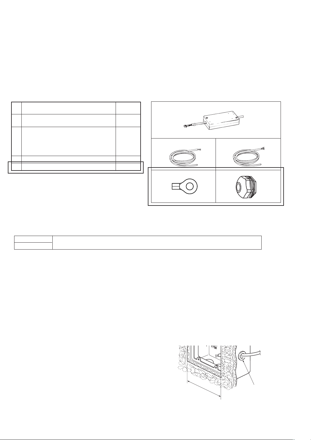
2. Accessory
The list of items to prepare at the installation site and the illustrations have been revised.
■
Items to Prepare at the Installation Site
2
, in
One per air
conditioner
1
One per air
conditioner
1
1
A
B
D
C
E
MA & Contact terminal interface
A
(MAC-397IF-E)
Power supply wire (2-core + ground) 1.5 mm
B
conformity with Design 245 IEC 57.
Connection wire
Wire specification
C CVV (3-core) 0.5 mm
* CVV is a control cable which is sheathed in poly-
vinyl chloride with polyvinyl insulated wires inside.
D Ring tongue ter minal for M4
E PG connection
2
or equivalent
P4
2-1. Selecting Compatible Models
The note (indicated with *) has been revised as follows.
*
Breaker capacity
10 A
Connect to the supply terminals and leave a contact separation of at least 3 mm at each pole to
disconnect the source power pole. (When the power switch is shut off, it must disconnect all poles.)
P6
3-1. Mounting Preparations
The text for step 3 and the lower right portion of the illustration to the right of the text have been revised.
3
Feed the power supply wire
inside of the wall, and pull them through the switch box 3 into the room
about 150 mm.
In addition, when not using a conduit for a connection wire C, be sure to
install a rubber seal (large) 5 or rubber seal (small) 6 into the hole in the
switch box 3 before feeding the connection wire C through the hole.
Use the PG connection E prepared at the installation site to secure the
power supply wire B in the hole in the switch box 3.
B, connection wire C
, and ground wire from
Switch box 3
Rubber seal (large) 5
Wall opening dimensions 108
PG connection E
✕ 3 mm
JG79C557H01
 Loading...