

Page 1
Centralized On-Off Remote Controller
MAC-821SC-E
[FOR INSTALLER]
INSTALLATION MANUAL
[FÜR INSTALLATEURE]
INSTALLATIONSHANDBUCH
[POUR L’INSTALLATEUR]
MANUEL D’INSTALLATION
[VOOR DE INSTALLATEUR]
INSTALLATIEHANDLEIDING
[PARA EL INSTALADOR]
MANUAL DE INSTALACIÓN
[PER L’INSTALLATORE]
MANUALE DI INSTALLAZIONE
English
Deutsch
Français
Nederlands
Español
Italiano
[°π∞ ∞À∆√¡ ¶√À ∫∞¡∂π ∆∏¡ ∂°∫∞∆∞™∆∞™∏]
E°XEIPI¢IO O¢H°IøN E°KATA™TA™H™
[PARA O INSTALADOR]
MANUAL DE INSTALAÇÃO
[TIL INSTALLATØREN]
INSTALLATIONSMANUAL
[FÖR INSTALLATÖREN]
INSTALLATIONSMANUAL
[MONTÖR ‹Ç‹N]
MONTAJ ELK‹TABI
[ДЛЯ УСТАНОВИТЕЛЯ]
РУКОВОДСТВО ПО УСТАНОВКЕ
[ ]
[ ]
∂ППЛУИО¿
Português
Dansk
Svenska
Türkçe
Русский
Page 2
Caution
To use this centralized controller, you must have a MA &
Contact Terminal Interface (MAC-397IF-E, sold separately)
for each air conditioner unit.
Contents
1. Safety Instructions .......................................................................................................................... 2
2. Accessory ....................................................................................................................................... 3
3. Mounting the Centralized Controller/Direct Wiring .......................................................................... 6
4. Mounting the Centralized Controller ............................................................................................... 8
5. Test Run.......................................................................................................................................... 9
6. Room Name Display ....................................................................................................................... 9
7. Specifications.................................................................................................................................. 9
1. Safety Instructions
• Read all Safety Instructions before using this device.
• This manual contains important safety information. Be sure to comply with all instructions.
• After installing the controller, provide this Installation Manual to the user.
Instruct users to store their room air conditioner Instruction Manual and Warranty in a safe location.
Warning
(Improper handling may have serious consequences, including injury or death.)
■ Users should not install the centralized controller themselves.
Improper installation may result in fire, electric shock, or damage/water leaks if the centralized controller falls. Consult the
retailer or specialty store where you purchased the unit for referral to an installer.
■ The centralized controller should be securely installed in accordance with the enclosed Installation Instructions.
Improper installation may result in fire, electric shock, or damage/water leaks if the centralized controller falls.
■ The unit should be mounted in a location that can support its weight.
If installed in an area that cannot support the unit, the centralized controller could fall and cause damage.
■ Securely attach the electrical component cover to the centralized controller.
If the electrical component cover of the centralized controller is not securely attached, dust or water penetration could occur,
resulting in a fire or electric shock.
■ Mitsubishi components or other designated components should be used for installation.
Improper installation may result in fire, electric shock, or damage/water leaks if the centralized controller falls.
■ When performing electrical work, adhere to the Technical Standards Regarding Electrical Equipment and the Interior Wiring Standards, follow the instructions provided in the Instruction Manual, and be sure to use a dedicated
circuit.
Inadequate circuit capacity or improper installation could result in a fire or electric shock.
2
Page 3

2. Accessory
Before installing the unit, make sure that you have all the necessary parts.
Centralized controller
A Cover
1
Remove the cover with a flathead screwdriver.
B Screw
2 Base plate 1
3 Switch box 1
4 Room name stickers 1
5 Rubber seal (large) 2
6 Rubber seal (small) 1
7 Sealing material (adhesive) 4
8 Mounting screw M4 × 30 2
■ Items to Prepare at the Installation Site
2
, in
One per air
conditioner
One per air
conditioner
MA & Contact terminal interface
A
(MAC-397IF-E)
Power supply wire (2-core + ground) 1.5 mm
B
conformity with Design 245 IEC 57.
Connection wire
Wire specification
C CVV (3-core) 0.5 mm
* CVV is a control cable which is sheathed in poly-
vinyl chloride with polyvinyl insulated wires inside.
D Ring tongue ter minal for M4
2
or equivalent
1
1
1
1 2
3
5
A
B
4
6
87
C
■ Mounting Wall
This centralized controller can be mounted on a wall with a thickness of 6–30 mm.
Since the maximum wall thickness for the centralized controller’s mounting screw M4 × 30 8 is 17 mm, use screws of the
appropriate length for the wall thickness if the wall is between 17 mm and 30 mm thick.
(The best length for an M4 mounting screw is the wall thickness plus 13 mm.)
3
Page 4
2-1. Selecting Compatible Models
The Installation Manual for the MA & Contact terminal interface (MAC-397IF-E) A contains a list of room air conditioner models
(sold separately) that are compatible with this centralized controller.
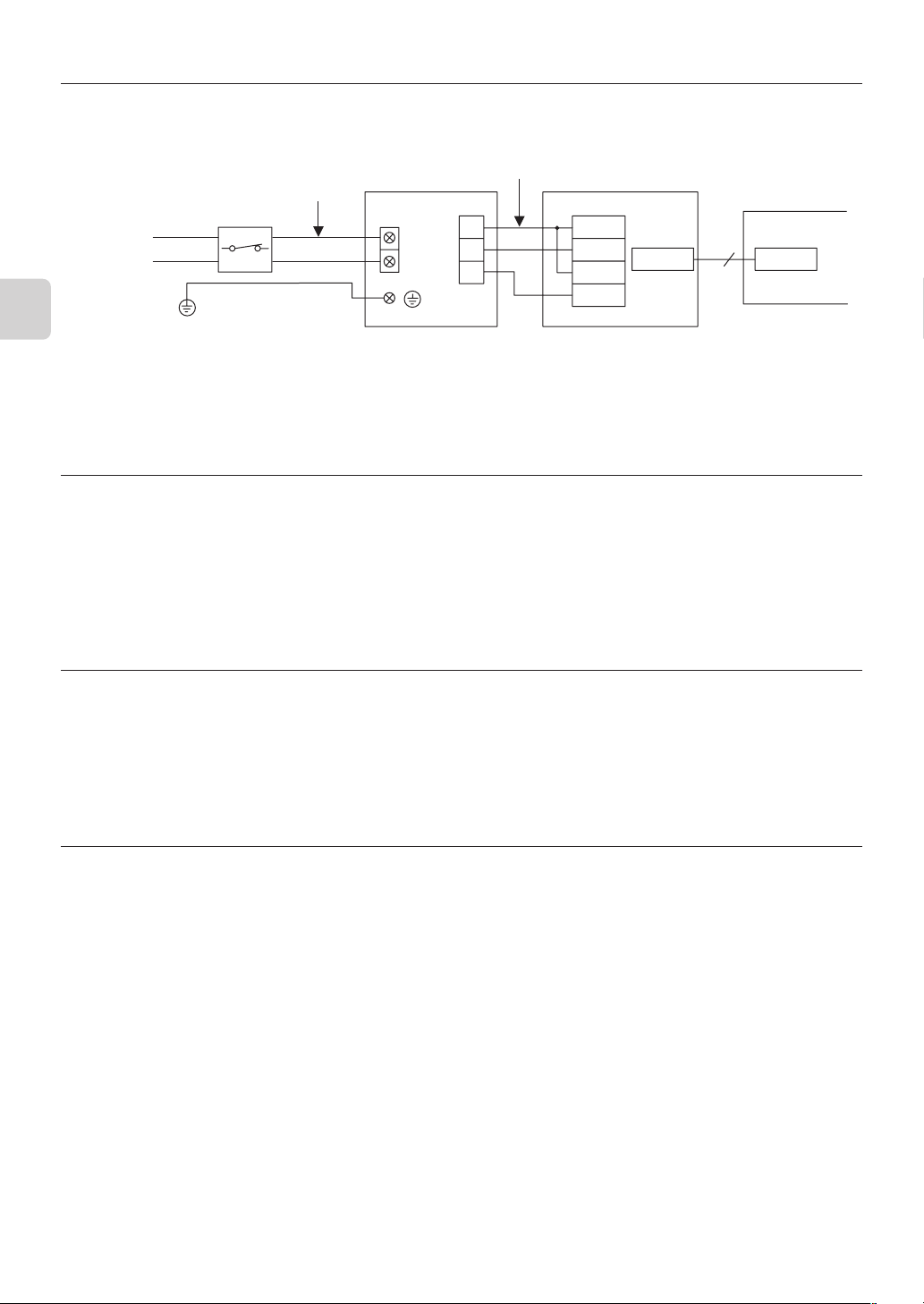
■ Connection Requirements
Power supply
~/N 220–240 V
50/60 Hz
Breaker *
Power supply wire B
L
N
Connection wire C
D
C
M
TB571
TC1
TC2
TM1
CN560
5
CN105
TM2
Ground
* Connect the power switch with gap of 3 mm or more when open to interrupt the source power phase. (When the
power switch is shut off, it must interrupt all phases.)
MAC-821SC-E
MAC-397IF-E
Air conditioner
Indoor unit
2-2. Selecting an Installation Site
• The centralized controller 1 is an exposed, wall-mounted model.
Install the unit in a dry location.
• For information on selecting a mounting wall, see the “Mounting Wall” in section 2.
■ Switch Box
The centralized controller power and connection wiring is generally direct wired.
The switch box 3 supplied (with switch box covers for 2 units) should therefore be used for installing the centralized controller.
2-3. Electrical Work
• Use 1.5 mm2 power supply wire (2-core + ground).
• For the connection wire C, use a control cable CVV (0.5 mm2 3-core) or equivalent product.
CVV is a control cable which is sheathed in polyvinyl chloride with polyvinyl insulated wires inside.
• Complete the power supply wire and connection wire work before mounting the centralized controller.
• The electrical work should be performed in accordance with the Technical Standards Regarding Electrical Equipment and the
Interior Wiring Standards.
2-4. Assigning Air Conditioner Device Numbers
• The numbers (1–8) displayed on the control panel of the centralized controller 1 correspond to the numbers of each connected
air conditioner (device number).
• Assign air conditioner device numbers that correspond to the numbers shown on the control panel based on the structure of the
building or the layout of the rooms in which the air conditioners are installed.
4
Page 5

2-5. Sample Configuration
This figure shows a sample 4-unit configuration.
Connection wire C (max. length of 100 m)
A/C Device No. 2
A/C Device No. 1
2-6. Mounting Diagram
A
A/C Device No. 3
A
Centralized controller 1
Base plate 2
Power supply
~/N 220–240 V 50/60 Hz
Switch box 3
A/C Device No.4
A MA & Contact terminal interface (MAC-397IF-E)
Connection wire C
(3-core)
Rubber seal
(large) 5
A
A
Connection wire C
(3-core)
Switch box 3
Power supply
wire B
Screw
Cover
Centralized controller 1
Mounting screw 8
M4 × 30
Sealing material 7
(adhesive)
Mounting screw
(M4 × 10)
Wall
Rubber seal (small) 6
5
Page 6

3. Mounting the Centralized Controller/Direct Wiring
3-1. Mounting Preparations
1
Remove 2 screws, and remove the base plate 2 from the switch box 3.
Set the 2 screws aside, as they will be used in the section on “4-1. Mounting
the Base Plate” under “Mounting the Centralized Controller”.
2
Insert the switch box 3 into the wall. Size the hole in the wall to ensure that
there is go gap between the switch box 3 and the wall surface.
Use the switch box 3 wall installation dimensions and opening dimensions
shown in the figure below.
3
Feed the power supply wire B, connection wire C, and ground wire from
inside of the wall, and pull them through the switch box 3 into the room
about 150 mm.
If you are not using a wire conduit, pull the wires through after attaching the
rubber seal (large) 5 and rubber seal (small) 6 to the switch box 3 opening through which the wires are being fed (to protect the wires from scraping
against the edge of the steel plate).
* Do not make the hole any larger than
Wall
Switch box 3
necessary.
Screw M4
Base plate 2
Switch box 3
Rubber seal (large) 5
Switch box 3
Wall opening dimensions
100 ± 3 mm
0–5 mm
150 mm
4
After the screws have been removed from the cover of the centralized controller 1, remove the cover using a flathead
screwdriver.
57 mm or more
Connection
wire C
Power supply wire B
Wall opening dimensions 108 ± 3 mm
Rubber seal (small) 6
6
Page 7

3-2. Connecting the Connection Wire
1
Connect the power supply wire (2-core + ground) B to the power terminal.
After they are connected, check that the wires cannot be easily pulled off.
Power terminal
Washer
Connection wire C
(3-core)
2
Mount the ground wire using the ground wire mounting screws.
Power supply wire B
(2-core + ground)
Signal terminal
Connection wire C
(3-core)
Work on Power Supply wire End
• Be sure to use 1.5 mm2 power supply
wire B (2-core + ground).
• The work on power supply wire end
should be performed as shown in the figure below.
80 mm
10 mm
Ring tongue
terminal for
M4 D
Ground
8 mm
3
Connect the connection wire (3-core) C to the MA & Contact terminal interface (MAC-397IF-E)
sponding to the air conditioner device number of each unit on the signal terminal.
• One signal terminal can be used for connecting 4 rooms.
Signal terminal
* Connect the devices corresponding to
their display number on the control panel.
• Connect the centralized controller to the adapters as shown below.
Connection wire (3-core)
Centralized
controller
D
C
M
TC1
TC2
TM1
MA & Contact
terminal interface A
Work on Connection Wire End
Note: Centralized controller side
6 mm
TM2
100 mm
AA
A, (sold separately) corre-
AA
7
Page 8

4. Mounting the Centralized Controller
4-1. Mounting the Base Plate
Insert the base plate 2 into the switch box 3, and remount it
using the screws removed in the “3-1 Mounting Preparations”.
Be sure to mount the base plate 2 so the up arrow is facing
upward.
Also, be careful not to damage the wires by getting them caught
between plate and the switch box 3.
Screw M4
Base plate 2
Up arrow
Screw
Switch box 3
4-2. Mounting the Centralized controller
1
Before mounting the unit, apply the supplied sealing materials 7
to the base plate 2, and fill in the space between the switch box
3 and the hole in the wall (a gap here could result in dew condensation).
Cut the sealing material 7 to a length such that it can be wrapped
around the hole in the wall based on the fixed position.
2
Connect the connection cord from the base plate 2 through the
slot in the centralized controller.
3
Mount the centralized controller to the base plate 2 using the supplied mounting screw 8.
Be careful not to damage the connection wires by getting them caught in the walling materials.
4
Using the supplied screw, attach the cover to the centralized controller.
5
To attach the cover to the centralized controller, fit the tabs along the top of the cover into the holes in the centralized controller
and then push the lower portion of the cover into place.
Caution
Be sure not to tighten the mounting screw 8 too tight.
Doing so may disfigure the centralized controller and prevent the cover from closing securely.
Centralized
controller 1
Base plate 2
Switch box 3
Wall
Base plate 2
Mounting screw 8
M4 × 30
Sealing material 7
* Pass through
the slotted hole
Mounting screw 8
M4 × 30
Cover
Screw
Centralized
controller
* Pass through the
slotted hole
Sealing
material 7
Connection wire C
Extra connection wire can be stored in the area
between the centralized controller and the cover.
8
Page 9

5. Test Run
A test run should be performed after the centralized controller and the MA & Contact terminal interface (MAC-397IF-E) have all
been installed.
1
Turn the power switch on each air conditioner to ON.
2
Press the ON/OFF button on the wireless remote control for each air conditioner to make sure the air conditioner turns on,
and then press the button again to turn each unit off.
3
Supply power (AC 220–240 V) to the centralized controller.
4
Press the ON/OFF button on the upper part of the control panel of the centralized controller, and confirm that the (green)
operation indicator lamp for that device number comes on.
Also confirm that the corresponding air conditioner has turned on (the operation indicator lamp will not come on if the air
conditioner is not connected).
5
Press the ON/OFF button again, and confirm that the operation indicator lamp goes out and that the air conditioner unit turns
off.
6
Repeat steps 4 and 5 again for each device number.
7
Press the All OFF button, and confirm that all the (green) operation indicator lamps go out and that all the air conditioners turn
off.
6. Room Name Display
Select the appropriate stickers from the room name stickers 4 supplied, and affix them to the display section of the panel.
Room name stickers 4
7. Specifications
Model MAC-821SC-E
No. of controlled air conditioners 8 units
Power ~/N, 220–240 V, 50/60 Hz
Power consumption 4 W
Ambient temperature 0–40°C
Dimensions (H × W × D) 120 × 120 × 51
Weight 320 g
9
Page 10

This product is designed and intended for use in the residential,
commercial and light-industrial environment.
The product at hand is based on
the following EU regulations:
HEAD OFFICE: MITSUBISHI DENKI BLDG., 2-2-3, MARUNOUCHI, CHIYODA-KU, TOKYO 100-8310, JAPAN
• Low Voltage Directive 73/23/EEC
• Electromagnetic Compatibility Directive 89/
336/EEC
Printed in JapanSG79Y547H01
Page 11

MAC-821SC-E
ERRATA
The following corrections have been made to the MAC-821SC-E INSTALLATION MANUAL.
P3
2. Accessory
The list of items to prepare at the installation site and the illustrations have been revised.
■
Items to Prepare at the Installation Site
2
, in
One per air
conditioner
1
One per air
conditioner
1
1
A
B
D
C
E
MA & Contact terminal interface
A
(MAC-397IF-E)
Power supply wire (2-core + ground) 1.5 mm
B
conformity with Design 245 IEC 57.
Connection wire
Wire specification
C CVV (3-core) 0.5 mm
* CVV is a control cable which is sheathed in poly-
vinyl chloride with polyvinyl insulated wires inside.
D Ring tongue ter minal for M4
E PG connection
2
or equivalent
P4
2-1. Selecting Compatible Models
The note (indicated with *) has been revised as follows.
*
Breaker capacity
10 A
Connect to the supply terminals and leave a contact separation of at least 3 mm at each pole to
disconnect the source power pole. (When the power switch is shut off, it must disconnect all poles.)
P6
3-1. Mounting Preparations
The text for step 3 and the lower right portion of the illustration to the right of the text have been revised.
3
Feed the power supply wire
inside of the wall, and pull them through the switch box 3 into the room
about 150 mm.
In addition, when not using a conduit for a connection wire C, be sure to
install a rubber seal (large) 5 or rubber seal (small) 6 into the hole in the
switch box 3 before feeding the connection wire C through the hole.
Use the PG connection E prepared at the installation site to secure the
power supply wire B in the hole in the switch box 3.
B, connection wire C
, and ground wire from
Switch box 3
Rubber seal (large) 5
Wall opening dimensions 108
PG connection E
✕ 3 mm
JG79C557H01
 Loading...