

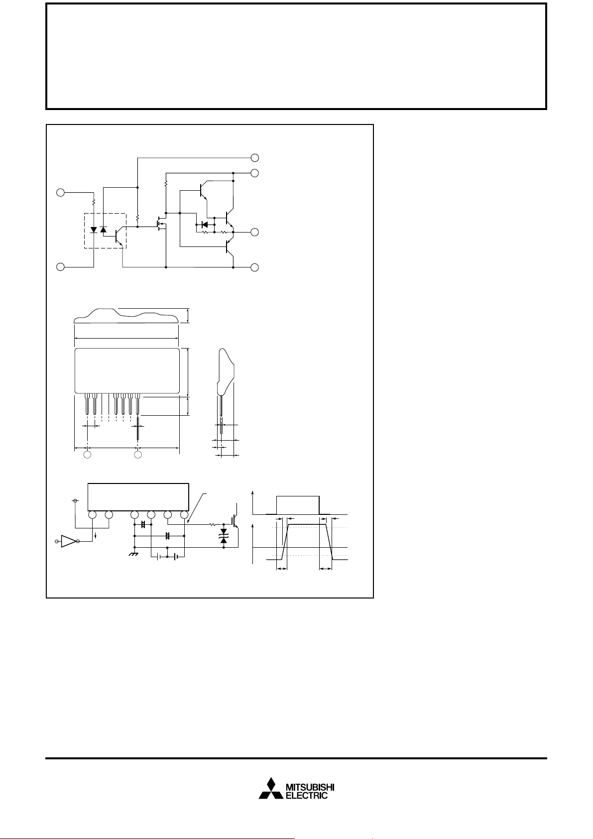
Block Diagram
2
185Ω
1
Outline Drawing
35 MAX
Dimensions in mm
10.0 MAX
MITSUBISHI HYBRID ICs
M57957L
HYBRID IC FOR DRIVING IGBT MODULES
Hybrid Integrated Circuit
For Driving IGBT Modules
5
6
7
8
Description:
M57957L is a hybrid integrated circuit designed for driving n-channel
IGBT modules in any gate amplifier
application. This device operates
as an isolation amplifier for these
modules and provides the required
electrical isolation between the input and output with an opto-coupler.
Features:
u Built in high CMRR opto-
coupler (V
CMR
: Typical
30kV/µs, Min. 15kV/µs)
M57957L
4.5 ± 1.5
+1.5
2.5
–1.0
Test Circuit
V
IN
TTL, etc.
2.54 ± 0.1
2.54 × 7 =
17.78 ± 0.2
1
2 5 6 7 8
16mA
81
M57957L
47µF
0.55 ± 0.1
+1.5
11.5
–1.0
C
ext
V
CC
= 15V
= 47µF
V
= 10V
EE
Precaution:
The value of “R
” should be selected according to the guidelines in
ext
Section 4.6.2 of Application Notes.
23 MAX
1.8 MAX
MEASUREMENT
POINT
R
ext
18V
0.35 ± 0.2
10.0 MAX
8.5 MAX
V
IN
V
OUT
0
u Electrical Isolation between in-
put and output with opto-couplers (V
V
RMS
= 2500,
iso
for 1 min.)
u TTL compatible input interface
u Two supply drive topology
u Short differential of propa-
gation time (t
PLH
, t
PHL
to Max.
1.5µs, Typical 1.0µs)
Application:
t
r
t
f
90%
10%
To drive IGBT modules for inverter,
AC Servo systems, UPS, CVCF inverter, and welding applications.
Recommended Modules:
V
t
PLH
t
PHL
= 600V Series
CES
(up to 200A Class)
V
= 1200V Series
CES
(up to 100A Class)
V
= 1400V Series
CES
(up to 100A Class)
Also, the value of “R
and I
are not exceeded.
OLP
” should be selected so that maximum limits, I
ext
OHP
Sep.1998

MITSUBISHI HYBRID ICs
M57957L
HYBRID IC FOR DRIVING IGBT MODULES
Absolute Maximum Ratings, Ta = 25°C unless otherwise specified
Item Symbol Ta (°C) Test Conditions Limit Units
Supply Voltage V
V
Input Voltage V
Output Voltage V
Output Current I
OHP
I
OLP
Output Current I
Isolation Voltage V
Junction Temperature T
Operating Temperature T
Storage T emperature t
*But differs from H/C condition.
CC
EE
I
O
OH
iso
j
opr
stg
25 DC 18 Volts
25 DC -12 Volts
25 Between Terminal 1 and 2 -1 ~ 7 Volts
25 Output Voltage “H” V
CC
Volts
25 Pulse Width 2µs, f = 30kHz -2 Amperes
25 Pulse Width 2µs, f = 30kHz 2 Amperes
25 f = 30kHz, DF = 50% 0.2 Amperes
25 Sinewave Voltage 60Hz, 1 min. 2500 V
rms
— 100 °C
— No Condensation -20 ~ 60 °C
— No Condensation *-25 ~ 100 °C
Electrical Characteristics, Ta = 25°C, VCC = 15V, VEE = –10V unless otherwise specified
VCC/V
EETa
Characteristics Symbol (°C) (°C) Test Conditions Min. Typ. Max. Units
Supply Voltage V
Pull-up Voltage on Input Side V
“H” Input Current I
“H” Output Voltage V
“L” Output Voltage V
Internal Power Dissipation P
“L-H” Propagation Time t
“L-H” Rise Time t
“H-L” Propagation Time t
Fall Time t
V
PLH
PHL
CC
EE
IN
IH
OH
OL
D
r
f
— 25 Recommended Range 14 15 — Volts
— 25 Recommended Range -9 -10 — Volts
— 25 Recommended Range 4.75 5.00 5.25 Volts
15/-10 25 VIN = 5V — 16 — mA
15/-10 25 13 14 — Volts
15/-10 25 -8 -9 — Volts
15/-10 25 f = 30kHz, DF = 50%, — 1.2 — Watts
Module 200A, 600V IGBT
15/-10 — VI = 0 to 4V, Tj = 100°C — 1.0 1.5 µs
15/-10 — VI = 0 to 4V, Tj = 100°C — 0.6 1.0 µs
15/-10 — VI = 5 to 0V, Tj = 100°C — 1.0 1.5 µs
15/-10 — VI = 5 to 0V, Tj = 100°C — 0.4 1.0 µs
Sep.1998
 Loading...