

Page 1
/
u
♦
INSTRUCTIONS
AND
PARTS
MITSUBISHI
INDUSTRIAL
SEWING
MODEL:
MACHINE
LZ-207
EMBROIDERY
BOOK
FOR
A
..•Mr
MITSUBISHI
ELECTRIC
CORPORATION
Page 2
Merits
Specifications
I.
Preparation
1.
Location
2.
Mounting
3.
Mounting
4.
Connection
5.
Mounting
6.
Mounting
7.
Mounting
8.
Mounting
9.
Note
n.
Gist
of
operation
1.
Selection
2.
Attaching
3.
Wind
4.
Ad.iustment
5.
Insertion
6.
Insertion
7.
Threading
8.
Changing
9.
Adjustment
10.
To
11.
Operation
12.
Adjustment
13.
Tension
14.
Tension
15.
Tension
16.
Adjustment
m.
Adjustment
1.
Timing
2.
Adjustment
3.
Adjustment
4.
Removal
5.
Regulation
IV.
Maintenance
1.
Lubrication
2,
Cleaning
for
for
thread
make
sewing
of
the
of
machine
of
motor
of
of
bobbin
of
spool
and
of
oil
the
of
thread
of
of
of
the
and
of
of
needle
of
stitches
of
of
of
threads
of
under
of
upper
of
of
needle
of
of
of
shuttle
of
INDEX
machine.
head
motor
lever
winder
stand
regulation
drop
pan
first
operation
needle
on
the
bobbin
bobbin
removal
upper
winder
bobbin
thread
basic-line
zig-zag
in a fixed
embroidery
needle
plate
thread
thread
auxiliary
and
shuttle
needle
needle
basic-line
bar
race
occurrence
and
treadle
of
knee
regulating
into
bobbin
of
the
bobbin
amplitude.
width
upper
thread
race
amplitude
of
amplitude
case
case
tension
motion
in
mechanism
into
the
regulator
straight
Page
shuttle
race
sewing ....
2
3
4
4
4
4
4
4
5
5
6
6
6
7
7
8
8
9
9
10
10
10
11
11
11
11
12
13
14
14
14
14
15
15
V.
Trouble
VI.
Parts
and
book
repairing
-1-
j0
20
Page 3
MERITS
Tl
11 ' -
ZIG-ZAG
The
maximum
can
embroider
easy
and
NEEDLE
Needle
center
amplitudes,
STITCH
Shuttle
correct
So,
even
sewing.
AUXILIARY
THREAD
The
auxiliary
with
each
fear
of
ful
embroidery.
QUIET
Timing
So,
quiet
WIDTH
smooth
BASIC-LINE POSITION
basic-line
and
right
SKIPPING
race
timing
at
TENSION
machine
uneven
OPERATION
belt
operation
AVAILABLE
zig-zag
beautiful
more
is
for
the
UPPER-THREAD
upper-thread
sewing,
is
amplitude
patterns.
by
knee
position
by
lever
beautiful
PREVENTER
designed
thread
maximum
rotation
thread
used
to
is
ensured.
mechanism.
setting
transmit
IS
of a needle
can
be
only.
and
varied
to
rotate
hooking
zig-zag
TENSION
tension
feeds
smoothly
snapping,
rotation
12. 7 mm{V2")
is
12. 7 mm
Zig-zag
CAN
changed
EQUIPPED
in
in
order
amplitude,
regulator
amplitude
BE
CHANGED
easily
In
combination
embroidery
variant
to
prevent
REGULATOR
which
the
thread.
etc., and
of
upper
(V2"')
can
be
adjusted
in 3 positions:
with
the
can
be
sewn.
speeds
you
you
motion
stitch
can
works
So,
can
and
lower
skipping.
get
beautiful
STABILIZES
in
connection
there
enjoy
yo''^
left,
zig-zag
and
to
is
no
beauti
shafts.
GREAT
Main
up
with
CONVENIENT
Needle
hole
ence
ZIG-ZAG
When
locknut
the
sewing
DURABILITY
parts
are
super
plate
partis
in
various
you
sew
without
and
made
of
finish,
is
designed
SEWING
which
REPLACEMENT
spring
in
applied
IS
in a definite
any
fear
enjoy
beautiful
special
fit-in
bush
sewings.
POSSIBLE
alloy
ensure
type
type
zig-zag
of
changing
sewing.
steel
well
long
and
smooth
OF
NEEDLE
and
its
replacement
in
order
to
IN A DEFINITE
amplitude,
the
zig-zag
heat-treated
use.
PLATE
is
easy.
give
facility
WIDTH
you
can
amplitude
and
and
keep
worked
Needle
conveni
it
by
through
Page 4
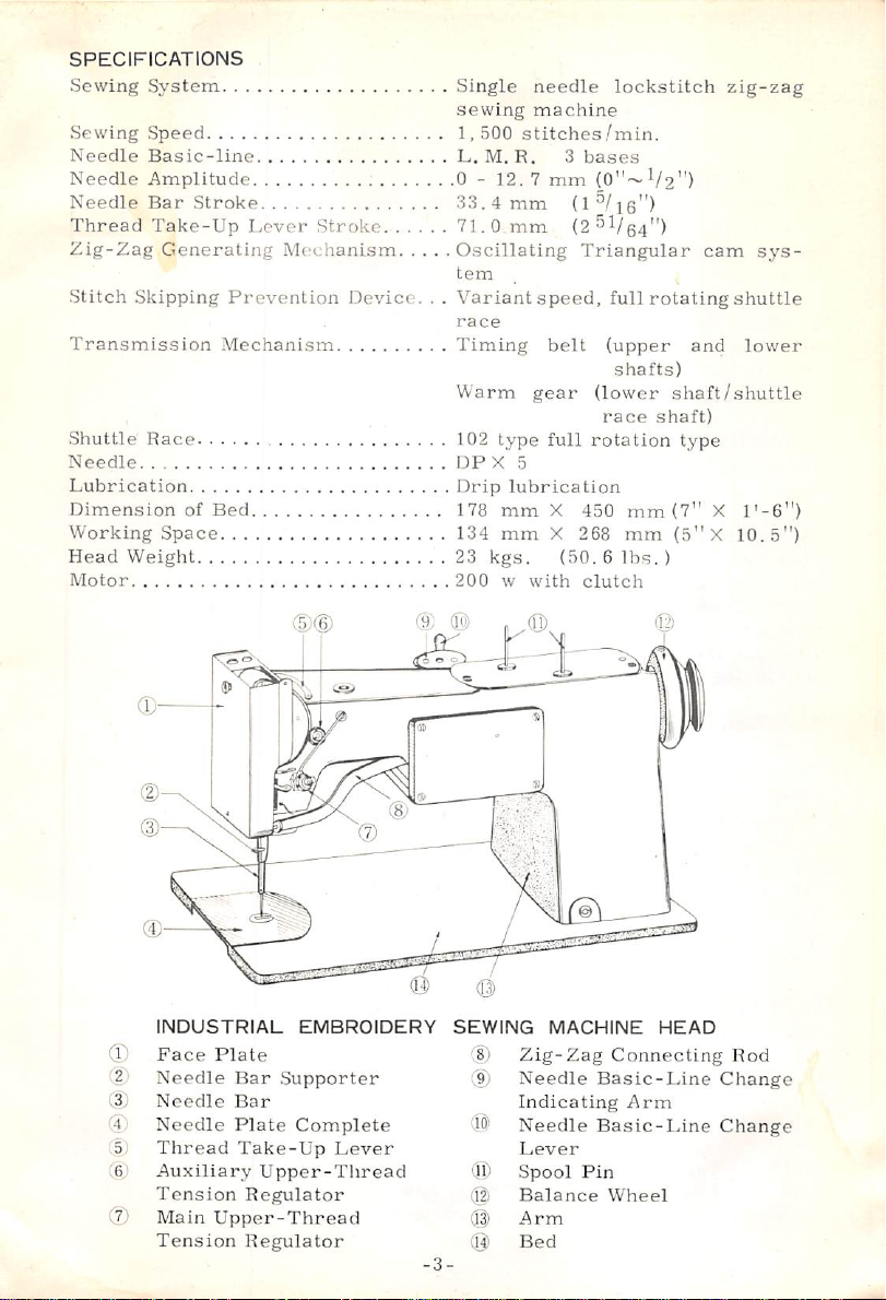
SPECIFICATIONS
Sewing
Sewing
Needle
Needle
Needle
Thread
Zig-Zag
Stitch
System
Speed
Basic-line
Amplitude
Bar
Stroke
Take-Up
Generating
Skipping
Transmission
Shuttle
Needle
Lubrication
Dimension
Working
Head
Motor
Race
of
Space
Weight
Lever
Mechanism
Prevention
Mechanism
Bed
Stroke
Device.
Single
sewing
1,500
stitches/min.
L.
M.
R. 3 bases
0 - 12. 7 mm
33.4
mm
71.0
mm
Oscillating
tem
. .
Variant
race
Timing
Warm
102
type
DP X 5
Drip
lubrication
178
mm
134
mm
23
kgs.
200 w with
needle
machine
(0"~
(1
/le")
(2^V64")
Triangular
speed,
belt
(upper
gear
(lower
race
full
rotation
X
450
X
268
(50. 6 lbs.)
clutch
lockstitch
V2")
cam
full
rotating
and
shafts)
shaft/shuttle
shaft)
type
mm
(7" X l'-6")
mm
(5"X
zig-zag
sys
shuttle
lower
10.5")
2
(32
(4.
■5;
(6,1
C7)
INDUSTRIAL
Face
Plate
Needle
Needle
Needle
Thread
Auxiliary
Tension
Main
Tension
Bar
Bar
Plate
Upper-Thread
(D®
EMBROIDERY
Supporter
Complete
Take-Up
Upper-Thread
Regulator
Regulator
Lever
@
-3-
SEWING
®
(9)
(©
®
(g;
®
(g)
^
MACHINE
Zig-Zag
Needle
Indicating
Needle
Lever
Spool
Pin
Balance
Arm
Bed
(12)
HEAD
Connecting
Basic-Line
Arm
Basic-Line
Wheel
Rod
Change
Change
Page 5
I.
PREPARATION
1.
LOCATION
In
order
your
sewing
machine
floor.
2.
MOUNTING
Accessory
on
the
back
Then,
3.
Motor
the
MOUNTING
is
washers
to
pass
balance
Then
connect
cord
extended
(Turn
runs
in
the
the
to
should
hinges
head
mounted
and
the
wheel
switch
correct
FOR
OF
THE
ensure
machine
be
OF
MACHINE
are
of
the
is
set
OF
MOTOR
nuts
on a position
belt
straight
slot
power
from
on
direction.
SEWING
MACHINE
smooth
without
set
to
be
bed
on
with
and
motor
supply
switch.
and
check
directionofsewingmachine
side
facing
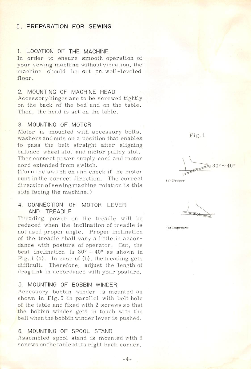
4.
CONNECTION
AND
Treading
reduced
not
used
of
the
dance
best
Fig. 1 (a).
difficult.
drag
link
the
TREADLE
power
when
proper
treadle
with
posture
inclination
In
Therefore,
in
accordance
machine.)
OF
on
the
inclination
angle.
shall
vary a little
of
is
30® - 40®
case
of
MOTOR
the
Proper
operator.
(b),
adjust
with
operation
vibration,
on.
well-leveled
HEAD
screwed
and
on
the
the
table.
accessory
that
after
pulley
cord
and
if
The
rotation
LEVER
treadle
of
inclination
as
the
treading
the
your
tightly
table.
bolts,
enables
aligning
slot.
motor
the
motor
correct
is
will
treadle
in
accor
But,
shown
length
posture.
of
the
this
be
is
the
in
gets
of
(a)
(b)
Prcippr
Improper
Fig.
1
30®~40=
5.
MOUNTING
Accessory
shown
of
the
belt
6.
in
the
table
bobbin
when
MOUNTING
Assembled
screws
on
OF
bobbin
Fig. 5 in
and
fixed
winder
the
bobbin
OF
spool
the
table
BOBBIN
winder
parallel
with 2 screws
gets
in
winder
SPOOL
stand
is
at
its
right
WINDER
is
with
touch
lever
STAND
mounted
back
mounted
belt
so
with
is
pushed.
with
corner.
-4-
as
hole
that
the
3
Page 6
7.
MOUNTING
KNEE
REGULATING
Knee
regulating
smooth
and
amplitude
When
knee
right,
the
returning
amplitude
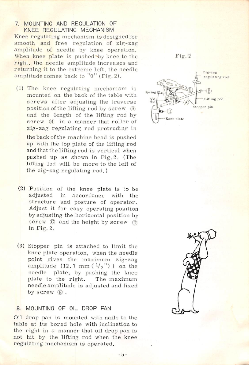
(1)
The
mounted
screws
position
and
the
screw
zig-zag
the
back
up
with
and
that
pushed
lifting
the
zig-zag
(2)
Position
adjusted
structure
Adjust
by
adjusting
screw © and
in
Fig.
AND
mechanism
free
of
needle
plate
needle
it
to
the
comes
knee
back
regulating
on
the
after
of
the
length
®
in a manner
regulating
of
the
the
top
the
lifting
up
as
lod
will
regulating
of
in
and
it
for
the
2.
REGULATION
MECHANISM
regulation
by
knee
is
pushed
amplitude
extreme
to
"O"
back
of
adjusting
lifting
of
rod
the
rod
machine
plate
of
rod
is
shown
be
the
in
more
knee
accordance
posture
easy
operating
horizontal
the
height
OF
is
designedfor
of
zig-zag
operation.
SDy
knee
increases
left,
the
needle
(Fig.
2).
mechanism
the
table
the
traverse
by
screw
lifting
that
rod
roller
protruding
head
is
pushed
the
lifting
vertical
Fig.
2.
to
the
left
rod.)
plate
is
with
of
operator.
position
position
by
screw
to
the
and
with
rod
when
(The
to
is
@
by
of
in
of
be
the
by
@
Spring
Knpr
Fig.
plate
2
7.1g-Z8g
Stopper
regulating
Lifting
rod
pin
rod
(3)
Stopper
knee
point
amplitude
needle
plate
needle
by
8.
MOUNTING
Oil
drop
table
at
the
right
not
hit
regulating
pin
plate
operation,
gives
(12.7
plate,
to
the
amplitude
screw © .
OF
pan
is
its
bored
in a manner
by
the
lifting
mechanism
is
attached
the
maximum
mm{
by
right.
is
OIL
DROP
mounted
hole
that
rod
is
to
when
the
V2") ) on
pushing
The
adjusted
PAN
with
nails
with
inclination
oil
drop
when
operated.
limit
needle
zig-zag
the
knee
maximum
and
fixed
to
pan
the
knee
-5-
the
the
the
to
is
Page 7
9.
NOTE
Prior
the-parts
to
the
Page
In
order
machine
stitches
FOR
to
the
requiring
item,
15.
to
ensure
for a long
approx.
operation,
concerning
using a machine.
n.
GIST
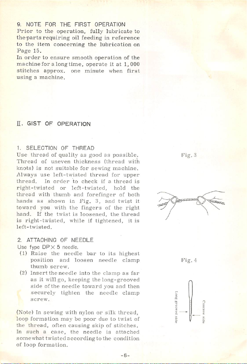
1.
SELECTION
Use
Thread
knots)
Always
thread.
right-twisted
thread
hands
toward
hand.
is
right-twisted,
left-twisted.
OF
thread
of
is
not
use
In
with
as
you
If
the
OPERATION
of
uneven
suitable
left-twisted
order
thumb
shown
with
twist
THE
FIRST
oil
feeding
smooth
time,
one
OF
THREAD
quality
as
thickness
for
to
check
or
left-twisted,
and
in
Fig.
the
fingers
is
loosened,
while
OPERATION
fully
lubricate
in
reference
the
lubrication
operation
operate
minute
good
it
when
as
(thread
sewing
thread
for
if a thread
forefinger
3, and
of
the
if
tightened,
to
on
of
the
at
1,000
first
possible.
with
machine.
upper
is
hold
the
of
both
twist
it
the
right
thread
it
is
Fig.
3
2.
ATTACHING
Use
type
(1)
Raise
position
thumb
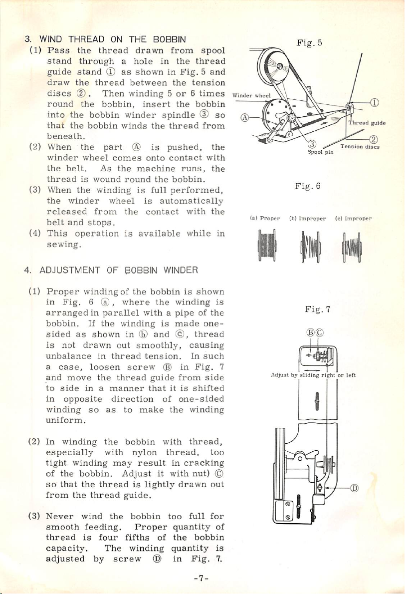
(2)
Insert
as
it
side
securely
screw.
(Note)
loop
the
In
In
formation
thread,
such a case,
somewhat
of
loop
formation.
OF
NEEDLE
DPX 5 needle.
the
needle
and
loosen
screw.
the
will
of
the
needle
go,
into
keeping
needle
tighten
sewing
twisted
with
may
often
nylon
be
causing
the
according
bar
needle
the
the
toward
the
or
poor
due
skip
needle
to
to
its
highest
clamp
clamp
as
long-grooved
you
and
then
needle
the
silk
thread,
to
twist
of
stitches.
is
attached
condition
clamp
-6-
Fig.
far
of
4
Page 8
3.
WIND
(1)
Pass
stand
guide
draw
discs
round
into
that
beneath.
(2)
When
winder
the
thread
(3)
When
the
released
belt
(4)
This
sewing.
4.
ADJUSTMENT
(1)
Proper
in
arranged
bobbin.
sided
is
unbalance
a
and
to
in
winding
uniform.
THREAD
the
ON
thread
through a hole
stand ® as
the
thread
(D . Then
the
bobbin,
the
bobbin
the
bobbin
the
part ® is
wheel
belt.
winder
and
is
the
stops.
wound
from
As
winding
wheel
operation
OF
winding
Fig. 6 ®,
in
parallel
If
the
as
shown
not
drawn
in
case,
move
side
loosen
the
in a manner
opposite
so
as
THE
BOBBIN
drawn
shown
between
from
in
in
the
the
Fig. 5 and
winding 5 or 6 times
insert
winder
winds
the
spindle
the
thread
pushed,
comes
thread
direction
the
machine
round
is
is
the
is
available
BOBBIN
of
the
where
with a pipe
winding
in
(E)
out
smoothly,
screw
thread
to
make
onto
contact
runs,
the
bobbin.
full
performed,
automatically-
contact
with
while
WINDER
bobbin
and
the
is
is
winding
made
©,
causing
tension.
(§)
in
guide
from
that
it
is
of
one-sided
the
spool
thread
tension
bobbin
(D
so
from
the
with
the
the
in
shown
is
of
the
one
thread
In
such
Fig.
side
shifted
winding
Winder
7
wheel
(b)
Pro
per
Adjust
Fig.
Fig.
(b)
Improper
by
sliding
5
Spool
6
Fig.
pin
(c)
7
right
Thread
Tension
Improper
or
left
guide
discs
(2)
In
especially
tight
of
so
from
(3)
Never
smooth
thread
capacity.
adjusted
winding
winding
the
that
the
the
with
may
bobbin.
the
thread
thread
wind
the
feeding.
is
four
The
by
screw
bobbin
nylon
result
Adjust
is
lightly
guide.
bobbin
Proper
fifths
winding
©
with
thread,
in
it
with
drawn
too
quantity
of
the
quantity
in
thread,
too
cracking
nut)
©
out
full
for
of
bobbin
is
Fig.
-7-
7.
Page 9
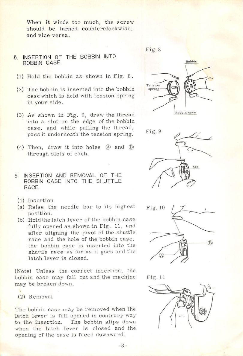
When
should
and
5.
INSERTION
BOBBIN
(1)
Hold
(2)
The
case
in
(3)
As
into a slot
case,
pass
it
be
vice
CASE
the
bobbin
which
your
side.
shown
and
it
underneath
winds
turned
versa.
OF
THE
bobbin
is
is
in
on
while
too
much,
counterclockwise,
BOBBIN
as
shown
inserted
held
with
Fig.
9,
draw
the
edge
pulling
the
tension
the
INTO
in
into
the
tension
the
of
the
the
screw
Fig.
8.
bobbin
spring
thread
bobbin
thread,
spring.
Fig.
Tens
ion
spring
Fig.
8
Bobbin
Bobbin
case
9
(4)
Then,
through
6.
INSERTION
BOBBIN
RAGE
(1)
Insertion
(a)
Raise
position.
(b)
Hold
fully
after
race
the
shuttle
latch
(Note)
bobbin
may
be
(2)
Removal
The
bobbin
latch
lever
to
the
when
opening
draw
slots
AND
CASE
the
the
latch
opened
aligning
and
the
bobbin
race
lever
Unless
case
may
broken
case
is
insertion.
the
latch
of
the
case
it
into
of
each.
REMOVAL
INTO
needle
lever
as
shown
the
hole
case
as
far
is
closed.
the
correct
fall
down.
may
full
opened
The
lever
is
holes
THE
bar
of
pivot
of
the
is
inserted
as
out
be
removed
bobbin
is
faced
OF
THE
SHUTTLE
to
its
the
bobbin
in
Fig.
of
the
bobbin
it
goes
insertion,
and
the
machine
when
in
contrary
slips
closed
downward.
and
highest
case
11,
and
shuttle
case,
into
the
and
the
the
the
way
down
and
the
p^g
xo
Fig.11
Page 10
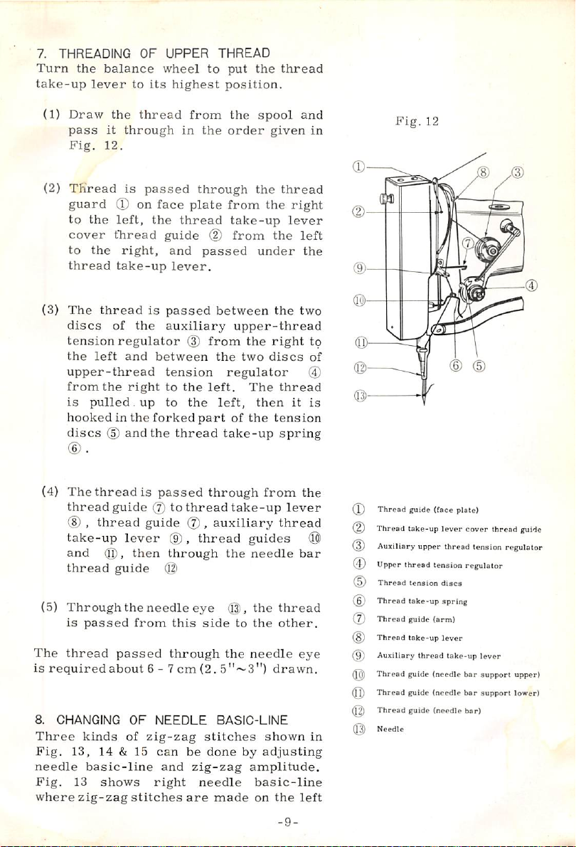
7.
THREADING
Turn
the
take-up
(1)
Draw
pass
Fig.
(2)
Thread
guard
to
cover
to
thread
(3)
The
discs
tension
the
upper-thread
from
is
hooked
discs
balance
lever
to
the
it
through
12.
is
(D
the
left,
tlaread
the
right,
take-up
thread
of
the
regulator
left
and
the
right
pulled,
in
the
(D
and
OF
UPPER
wheel
its
highest
thread
passed
on
face
the
thread
guide
and
lever.
is
passed
auxiliary
between
tension
to
up
to
forked
the
thread
THREAD
to
from
in
the
through
plate
(2)
passed
between
(3)
from
the
the
left.
the
left,
part
put
the
thread
position.
the
spool
order
from
given
the
the
take-up
from
the
thread
right
lever
under
the
upper-thread
the
right
two
discs
regulator
The
thread
then
it
of
the
tension
take-up
spring
and
in
left
the
two
to
of
is
Fig.
12
(4)
The
thread
(8) , thread
take-up
and
thread
(5)
Through
is
The
thread
is
required
8.
CHANGING
Three
Fig.
13,
needle
Fig.
13
where
zig-zag
thread
passed
kinds
basic-line
is
guide
lever
then
guide
the
from
passed
about
OF
of
14 & 15
shows
stitches
passed
(j)
to
thread
guide
(7),
(9),
through
(l|)
needle
eye
this
through
6-7
cm
NEEDLE
zig-zag
can
be
and
zig-zag
right
are
through
take-up
auxiliary
thread
the
(Q),
side
to
the
(2.
5"~3")
BASIC-LINE
stitches
done
by
needle
made
from
the
lever
thread
guides
needle
the
the
needle
shown
adjusting
amplitude.
basic-line
on
(0)
bar
thread
other.
eye
drawn.
the
left
-9-
in
Thread
Thread
0)
Auxiliary
(J)
Upper
Thread
Thread
(7)
Thread
Thread
@
Auxiliary
^
Thread
Thread
^
Thread
(13)
Needle
guide
(face
take-up
upper
tliread
tension
tension
take-up
guide
iann)
take-up
thread
guide
(needle
guide
(needle
guide
(needle
plate]
lever
cover
thread
tension
regulator
discs
spring
lever
take-up
lever
bar
support
t»r
support
bar)
thread
guide
regulator
upper)
lower)
Page 11

side
of
the
zig-zag
on
Fig.
zig-zag
of
basic-line
Fig.
operated.
needle
set
the
needle
hole © .
on
®
the
is
you
When
stitches
the
both
15
shows
stitches
the
basic-line.
16
on
basic-line
the
lever @ to
needle
basic-line
the
adjusted
is
set
stitches
set
on
the
can
get
it
is
machine),
in
Fig.
15.
9.
ADJUSTMENT
basic-line.
are
sides
of
the
left
needle
are
made
To
as
shown
the
back
To
operate
change
the
basic-line
change
Then,
you
on
the
as
left
the
stitches
set
on
can
the
lever © can
position.
center
shown
hole
the
get
OF
Fig.
14
shows
made
required,
in
equal
needle
change
above, a lever
of
knob
proper
basic-line.
basic-line
on
the
right
the
the
machine
lever @ ,
(B)
in
position
and
knob ® to
When
hole,
in
Fig.
(facing
as
shown
right
hole
the
stitches
ZIG-ZAG
the
you
14.
the
machine),
in
(facing
as
AMPLITUDE
that
width
where
side
needle
in
is
draw
FiglS,
of
set
the
bracket
be
fixed
lever
can
get
When
it
Fig.
13.
the
shown
Fig.13
Fig.
14
Fig.
15
Zig-zag
to
easy
of
the
of
sewing
to
the
10.
In
amplitude,
operate
amplitude
of
stitch,
Now,
amplitude.
11.
Put
frame,
position,
neath
thread
balance
amplitude
12. 7 mm
and
free
knee
regulating
with a fixed
next
item.
TO
MAKE
order
to
loosen
the
to
and
you
can
OPERATION
cloth into
raise
put
the
needle.
end
by
wheel
(0"~
V2")-
by
STITCHES
get
stitches
thumb
knee
the
necessary
tighten
sew
OF
accessory
the
the
embroidery
Holding
the
left
toward
can
be
adjusted
It
can
operating
mechanism.
zig-zag
IN A FIXED
in a fixed
nut © in
plate
until
the
thumb
in
the
EMBROIDERY
needle
at
lightly
hand,
turn
you,
and
from
be
adjusted
the
knee
In
width,
Fig.
the
zig-zag
nut
fixed
zig-zag
embroidery
its
highest
frame
under
the
slowly
the
-10-
plate
case
refer
WIDTH
needle
16,
needle
width
©)
upper
the
upper
0
Fig.
16
.
Page 12

thread
thread.
the
the
the
dery
by
tionrequires
better
enced
12.
Needle
spring
When
adjust
needle
left.
13.
Usually,
tensions
are
loos
Tension
conditions
thread,
required
comes
Then,
two
threads,
two
threads
drawing
frame
the
knee
have
with
ADJUSTMENT
plate
action
the
the
plate ® in
TENSION
the
are,
sewn.
of
thread
of
zig-zag
to
on
and
plate
some
good
the
is
needle
needle
Proper
threads
of
adjust
out
you
twined
can
with
start
to
After 2 or 3 stitches,
free
and
embroider
cloth
by
moving
regulating
zig-zag
mechanism.
skilfulness
practice
machine.
attached
so
as
does
OF
THREADS
less
the
in
use,
tobe
OF
NEEDLE
on
to
be
not
position
Fig.
17
upper
and
better
tension
stitch
varies
i.e.
kind
width,
it
each
good
the
removed
drop
by
to
under
zig-zag
does
on
according
of
etc., so
situation.
the
under
sew
holding
along
the
embroi
width
This
opera-
and
you
had
experi
PLATE
head
with
easily.
smoothly,
sliding
the
right
thread
stitches
not
be
the
cloth.
materials,
it
set
the
or
too
to
is
Fig.
17
a
14.
TENSION
Tension
(0.
35 - 0,
and
15 - 20 g {0.
medium
the
tension,
regulating
and
to
decrease
15.
TENSION
Tension
regulated
tension
regulator
made
spring
(1)
by
action
Pressure
In
almost
available
of
the
OF
UNDER
of
under
thread
52
oz)
for
52 - 0.
and
thick
turn
screw ® in
turn
OF
UPPER
of
the
upper
by
adjusting
discs
in
the
and
then
adjusting
range
of
Tension
all
merely
tension
THREAD
should
sewing
70
materials.
the
bobbin
Fig.
it
counterclockwise,
THREAD
thread
the
pressure
upper-thread
fine
regulation
the
thread
and
strength.
Discs
cases,
by
discs.
proper
adjusting
To
be
thin
materials
oz)
for
To
case
18
clockwise
is
tension
increase
10 - 15
sewing
increase
tension
roughly
of
the
tension
is
to
be
take-up
is
pressure
the
-11-
g
Fig.18
Thread
tension
spring
Page 13

tension,
(2)
thumb
to
decrease,
Thread
Proper
take-up
the
hook
turn
nut
Take-Up
position
spring
upper
turns
adjustment,
Fig.
20
and
to
clockwise
(Tighten
adjustment)
(3)
Thread
Approximate
for
spring.
and
split
clockwise
counterclockwise
(Tighten
adjustment)
16.
ADJUSTMENT
THREAD
In
case
tension
of
it
is
lever
auxiliary
begins
position
from
take-up
thread
back
of
screw
When
early,
busing a little.
ments,
thread
enjoy
tension
important
Take-Up
the
strength
Loosen
insert
of
the
TENSION
that
regulator
released
gets
near
upper-thread
to
press
of 3 mm - 6
the
highest
lever.
is
too
the
tension
in a notched
release
adjust
unlike
tension
beautiful
of
thread.
in
embroidering.
the
(F'
in
Fig.
turn
starts
thread
round
loosen
turn
the
or
fast
the
20 g (0.
a
screw
tension
to
decrease
fast
the
OF
the
auxiliary
is
duly
when
its
highest
the
position
When
late,
loosen
bush
of
the
it
by
After
usual
regulator
sewing
tension
19
it
counterclockwise.
Spring
is
where
hooked
180
regulating
clockwise
Action
the
the
action
by
the
degrees.
screw
stopper ® either
counterclockwise.
screw
Spring
screw © in
to
AUXILIARY
Strength
70
oz)
of
thread
driver
stud.
the
increase
screw
REGULATOR
is
standard
take-up
Fig.
into
Turn
strength
it.
(©
UPPER-
upper-thread
adjusted,
the
thread
position.
tension
upper
mm
(V8"~V4")
release
discs
showed
upper
loosening
these
adjustment
with
This
regulator
thread
of
the
of
the
locknut
in
Fig.
in
thread
the
correct
of
only,
the
is
the
Fig.
you
and
Range
thread
when
shuttle
For
C
in
after
21
the
it
and
after
tension
take-up
This
at
the
down
thread
upper
at
the
22
and
22.
is
too
noched
adjust
upper-
can
lightest
most
Fig.19
to
Fig.20
\
Fig.
Thread
spring
Fig.22
to
Lock
to
<icc
Trnaion
(Thread
btnppc
21
take-up,
loos
nut
quicker
(Pressure
regulating
ldke>up
Thread
of
to
spring
take-up
Tension
to
tighten
tension
increase
thumb
action
spring
to
Notched
discs)
nut
range)
strength)
decrea.se
stud
bushing
-12-
Page 14

in.
ADJUSTMENT
1.
TIMING
OF
NEEDLE
AND
SHUTTLE
RACE
Fig.23
Tip
of
shuttle
hook
Timing
the
and
with
mark
standard
the
shuttle
the
supporter
the
middle
tude
is
at
DP X 5
as
its
mark
the
turning
that
the
raised
position
a
timing
lowest
(Note)
kind
mentioned.
the
is
To
the
that
to
when
left
upper
used,
follows.
lowest
are
needle
the
the
center
3.2
as
position
mark
part
Adjustment
of
materials,
shuttle
to
be
make
shuttle
the
tip
the
upper
the
or
to
thread.
in
the
of
proper
race
lowest
when
the
position
"0".
the
When
position,
to
match
bar
supporter.
balance
tip
of
the
line
of
the
mm
shown
of
under
matches
of
the
Clearance
hook
and
adjusted
sure
of
race,
of
the
part
needle
the
right,
needle
timing
is
adjusted
tip
of
needle
and
the
So,
in
case
standard
the
needle
the
lines
with
wheel
shuttle
needle
(V0")
in
Fig.
line
from
23.
approximately
needle
bar
varies
but
the
standard
between
the
needle
as
0.05
timing
it
is
necessary
shuttle
basic-line
hook
of
the
to
catch a loop
bar
which
of
the
to
the
needle
basic-line
zig-zag
of
the
adjustment
bar
on
two
the
lowest
Then,
adjust
toward
hook
match
when
the
its
In
this
of
the
needle
supporter.
according
is
the
side
(Fig.
mm
of
the
needle
to
passes
needle
is
eye,
set
shows
needle
match
bar
is
ampli
needle
goes
timing
tip
by
you
so
with
needle
lowest
case,
bar
to
the
to
the
above
tip
24)
approx.
and
confirm
close
even
to
the
of
the
in
is
to
of
of
The
Fig.
Tip
of
Fig.25
Needle
connecting
lowest
24
shuttle
bar
position
hook
stud
0.
05mm
Less
3.
ttian
2mm
raised
(^/b")
(1)
Height
releasing
connecting
tighten
(2)
Timing
needle
adjusting
wheel
the
adjustment,
of
the
screw
after
of
is
screws
(under)
shuttle
needle
stud
in
adjusted.
the
shuttle
adjusted
in
Fig. 2 6
race
the
screw
®
Fig.
in
by
is
adjusted
of
needle
25
race
by
the
timing
and
hand.
should
by
bar
which
and
is
the
releasing
belt
turning
After
be
Fig.
26
Timing
yldjusting
be
screw
tightened.
-13-
Page 15

(3)
For
adjustment
the
tip
needle
shaft
When
are
in
part
too
large,
you
by
the
screw
2.
ADJUSTMENT
To
make
the
each
needle
to
move
right
or
to
loosening
®
of
the
and
turn
the
wise
or
counterclockwise.
ment,
fast.
3.
the
ADJUSTMENT
AMPLITUDE
i\mplitude
before
so
parallel
ring
cam.
shown
releasing
(Note)
is
the
important,
with
of
helical
It
is
in
the
When
harmed.
of
the
side,
release
bushing
the
needle
touch
©
and
pull
hand
for
©
OF
uniform
basic-line,
slightly
the
left.
the
set
needle
eccentric
set
screw
OF
MOTION
motion
needle
for
the
needle
gear
necessary
Fig.
28
zig-zag
the
needle
of
clearance
shuttle
set
screw © in
and
with,
when
the
hook
the
the
push
the
shuttle
correction
NEEDLE
the
needle
it
the
needle
For
the
screw
bar
of
support
pin ® to
must
NEEDLE
of
the
needle
penetration
it
gives
influence
motion.
on
the
main
to
adjust
when
the
needle
shaft
helical
amplitude
between
and
shuttle
race
Fig.
shuttle
the
race
screw
clearance
race
toward
and
tighten
BASICLINE
dropping
is
necessary
bar
to
adjustment,
eccentric
in
Fig.
the
clock
i^fter
adjust
be
tightened
BAR
bar
should
into
the
clotli.
to
ildjustment
shaft
the
triangular
bar
gear
motion
the
27.
is
on
the
pin
25
the
and
gets
set
is
Fig.27
Shuttle
Shuttle
Fig.
Fig.29
be
adjusted
Timing
motion
is
helical
cam
to
screw.
too
low,
race
hook
stoppe
28
' ® ®
of
of
the
done
by
gear
to
be
its
lowest
sometimes
Left
needle
Middle
needle
Right
needle
so
as
to
this
motion
shuttle
changing
on
triangular
in
the
position
position
the
basic-line
basic-line
basic-line
finish
race
gea
cloth
is
in
by
4.
REMOVAL
(1)
Remove
(2)
When
forward.
of
screw
shuttle
5.
REGULATION
Putting a sheet
toward
needle
you
traces
OF
screw
screw
©
race
by
SHUTTLE
©
©
is
When
it
after
is
loosened.
OF
OCCURRENCE
of
paper
hand
to
appears
RACE
of
Fig.
removed,
is
too
tight
screw
on
make
in
double
27
and
the
to
©
is
OF
the
needle
needle
points,
disconnect
shuttle
be
drawn
shuttle
race
out,
lightly
can
hook
be
loosened 2 or 3 times,
AMPLITUDE
plate,
traces
loosen
-14-
on
screw
IN
turn
the
STRAIGHT
the
balance
paper.
(a)
tap
in
stopper.
drawn
the
head
then
SEWING
wheel
When
Fig.
29
out
the
the
in
Page 16

a
projection
regulate
become
ment
and
so
single
of
zig-zag
loosening
regulation
line
on
the
IV.
MAINTENANCE
on
that
is
given
left
the
back
the
double
point
by
adjusting
screw
for
or
on
the
up
and
©
the
right.
of
the
pointed
down
arm
.
The
needle
arm
and
traces
move
tightening
same
basic-
Fig.
30
For a long
condition,
required.
1.
LUBRICATION
The
most
important
is
lubrication.
of
the
machine
and
tear. A plenty
(1)
Parts
(a)
Lubricate
Fig.
30,
(b)
Lubricate
marked
into
the
(c)
Dust
required
the
dust
is
not
(d)
After
slightly
soak
of
lubricate
revolving
out.
Into
and
each
after
arm.
use
of
the
constant
and
care
If
you
neglect
shortens
of
oil
is
and
Quantity
in
the
31,
32 & 33.
5-6
drops
Q—^
parts
marked
on
parts
should
absorbs
efficient
lubricating,
for
into
groove,
taking
where
be
oil
on
the
operate
about 1 minute
the
motion
into
take
the
main
link
in
the
off a lid
machine
good
of
the
it,
in
care
machine
the
with a heavy
required
of
Lubrication
arrowed
and
into
1-2
always.
parts
the
^
lubrication
cleaned
and
the
dust.
away,
lubrication
the
machine
so
parts.
the
shuttle
the
bobbin
shaft helical
arm.
lubricate
on
the
top
good
wear
parts
drops
as
In
race
gear
of
is
life
in
is
for
to
case
case
the
Fig.31
Fig.32
Fig.33
2.
CLEANING
Clean
shuttle
which
away
race
will
occasionally
parts
cause
poor
and
thread
dust
each
covering
thread
tension.
-15-
path
Page 17

V.
Trouble
Faulty
Condition
1.
Stitch
Skipping
and
repairing
(1)
a.
b.
c.
(2)
a.
b.
c.
(3)
Faulty
Causes
Faulty
Bent
Poor
soft)
Needlenot
ing
needle
needle
quality
thread
Faulty
mounting
Not
sufficiently
Gap
Needle
Faced
direction
Point
hook
broken.
is
in
of
tip
is
Proper
(too
match
needle
inserted
remains
twisted
wrong
shuttle
dull
or
Replace
Replace
with
with
quality.
Replace
thread
Insert
Face
with
thickness.
to
the
the
side-ways;
observing
of
nylon
Mount
grooved
concave
Correct
stone
or
needle
side
side
or
replace
loop
the
Remedy
new
needle
needle
fullest
needle
twist
slightly
condition
tetoron
so
faces
faces
tip
with
needle.
of
matching
depth.
eye
directly
in
thread.
that
the
left
the
with
new
better
while
case
long
and
right.
grind
one.
(4)
Clearance
ween
ttle
needle
(5)
Position
too
(6)
race
a.
Shuttle
b.
point
hook
high
Needle
not
properly
advanced
Shuttle
delayed
too
and
of
tip
large
of
needle
or
low
shuttle
meeting
race
race
bet
shu
and
too
too
-16-
Correct
so
that
0.
05mm
i^djust
mark
in
13)
Correct
so
that
to
center
needle
lowest
is
position.
shuttle
the
clearance
(about
by
needle
hair
regulating
bar.
shuttle
shuttle
line
raised
hook
of
hook
race
(See
position
will
thickness).
timing
(See
page
position
tip
comes
needle
3.
2mm
when
from
page
be
13)
Page 18

Faulty
Condition
2.
Loose
Stitches
(1)
Pressure
tension
enough
(2)
Weak
take-up
(3)
Small
operation
thread
spring
(4)
Weak
thread
(5)
Thread
not
a.
Non-uniform
thread
b.
Hand-wound
is
used
c.
Dust
discs
d.
Improper
excessive
of
bobbin
e.
Dust
case
f.
Thread
spring
case
bent
g.
Bobbin
improperly
Causes
tension
uniform
thickness
in
thread
in
of
distorted
discs
thread
spring
range
take-up
under-
strength
spool
tension
winding
bobbin
tension
bobbin
inserted
not
or
on
or
of
of
of
i^djust
by
regulating
right
little
strengthen.
item
15)
Strengthen
tension
stud
Strengthen
fabrics
page
Increase
the
15)
Adjust
ning
bobbin
14)
Use
Use
Hand-wound
draw-out
(large
12,
item
by
left.
(See
while
thread
case
quality
machine-wound
of
Disassemble
tension
tension
and
tension
of
Rewind
winding
with
7,
Remove
Correct
one.
Check
correct.
polish
tension
bobbin
item
regulator
regulating
stud
discs.
bobbin
capacity
3).
dust.
or
bobbin
(See
Remedy
turning
thumb
by
little
(See
by
gradually
to
when
sewing
stitches)
15)
turning
page
gradually
tension
(See
page
machine
spool
thread.
upper-thread
by
thread-path
and
inner
up
pipe.
replace
insertion
page
tension
nut
to
in
order
page
turning
the
right.
stopper
12,
tighte
screw
11,
thread.
spool.
offers
removing
thumb
surface
to
80%
in
parallel
(See
il^nfi
with
8,
item
the
to
12,
thick
(See
to
item
of
item
poor
nut
of
of
page
new
if
5)
-17-
Page 19

Faulty
Condition
3.
Break
thread
of
(1)
Improper
a.
Poor
b.
Use
twisted
thread
c.
Thread
for
(2)
Improper
a.
Bent
b.
Poor
needle
eye
c.
Needle
improperly
d.
Needle
for
Causes
quality
of
needle
needle
finish
thread
thread
right-
upper-
too
large
needle
groove
mounted
too
thin
of
or
Replace
of
good
ununiform
cannot
Change
Replace
thickness.
Replace
Replace
quality.
Refer
(2),
Replace
be
with
to
page
with
with
with
Skipped
with
Remedy
with
machine
quality.
thickness
used.
left-twisted
thread
new
needle.
needle
stitches,
17.
suitable
thread
Thread
or
knotty
thred.
in
proper
of
better
item
needle.
in
(3)
Upper-thread
tension
(4)
Action
take-up
too
(5)
Thread
spring
quick
too
of
take-up
too
strong
thread
spring
strong
-18-
Weaken
tension
to
the
used
recheck
stitches)
15)
Delay
stopper
12,
Weaken
to
the
used
recheck
stitches)
regulating
left
to
prevent
the
to
item
by
left
to
prevent
(Seepage
tension
the
(See
action
15)
the
(If
strong
loose
causes
page,
the
left
turning
(If
strong
loose
cause
by
thumb
tension
stitches,
of
12
by
turning
(See
tension
tension
stitches,
of
12,
item
turning
nut
is
loose
item
the
page
stud
is
loose
15)
Page 20

Faulty
Condition
Causes
Remedy
Break
thread
of
(6)
Shuttle
bobbin
race
or
case
Correct
with
grindstone.
injured
(7)
(8)
(9)
Needle
needle
injured
Ununiform
strength
Needle
race
not
properly
and
hole
thread
shuttle
meeti
on
plate
-g
Polish
needle
caused
moved
tion,
Refer
(5),
Correct
race
item
hole
or
plate.
if
material
during
or
if
bent
to
Loose
page
17.
the
mounting
1)
replace
{Injury
is
sewing
needle
stitches,
position
(See
with
may
forcibly
opera
is
used.)
item
of
shuttle
page
new
be
13,
-19-
Page 21

MEMO
Page 22

71
PARTS
BOOK
Industrial
Remarks : Whenorderingparts,
and
its
figure
ZIG-ZAG
number.
be
sure
Sewing
to
include
Machine
model
number,
parts
number
Page 23

.lD
-22-
CO
Page 24

Arm
bed
and
its
accessories
Fig
Parts
Na
1
W110516
2
W322326
3
B509091
4
W500211
5
W448583
6
W445617
7
W500906
8
W444138
9
10
11
12
13
14
15
16
17
18
19
20
21
22
23
24
25
26
27
415206
B422836
W501728
W500149
W453519
W501925
W452939
B509179
B659592
W451064
NaO X 5
W450620
B503846
W502386
W452915
W452912
W502365
W502366
W452913
Fig
Parts
Ni
28
W445933
29
W502367
30
W452914
31
W500655
32
W500307
33
W452909
34
W500994
35
B509264
W44S942
36
W501391
37
38
W446986
39
W447016
40
W445933
41
W447017
42
W446985
43
W501296
44
W444076
45
W501297
46
47
48
49
50
51
52
53
Nal5
W452917
W452918
W452919
W500591
W452920
W502368
W500370
Page 25

-24-
Page 26

I
Main
Fig
54
55
56
57
58
59
60
61
62
63
64
65
66
67
68
69
70
71
72
73
74
75
shaft
Parts
W322327
W446384
W500006
W452922
W452925
W501391
W452924
B508971
W452921
W500076
W446385
W446386
W500833
D
FX
W452927
W445883
W444138
B509087
W445881
W452923
W452926
W500294
and
Na
5
its
accessories
Fig
77
78
79
80
81
82
83
84
85
86
87
88
89
90
91
92
93
94
95
96
97
98
Na
Parts
B503851
W500306
W502371
W500036
W502372
W501167
W446397
W501168
W501017
W322328
W446457
B411094
W446560
B509256
W447023
W320112
B509060
B509054
W501177
W452932
B504016
Na
W452928
76
Page 27

138
137
1
' 119
139
108
^
n
'106
125
116
148
<2/146
Page 28

Fig
100
101
102
103
104
105
99
106
107
108
109
110
111
112
113
114
115
116
117
118
119
120
Na
Parts
W322330
W446387
W500089
W452940
W452941
B504016
W446456
W500036
W501167
W448092
B503842
W452942
W452943
B509069
B 8 S
B508961
W502374
W452944
W452945
W452946
W452947
B509289
Ml
Fig
124
125
126
127
128
129
130
131
132
133
134
135
136
137
138
139
140
141
142
143
144
145
^
Parts
W502378
W452952
W452954
W501845
W501009
W500102
B504016
W452955
W502382
W502383
W502384
W501758
W501031
W502379
B509064
W502380
W501550
W452949
W501540
W500245
W452950
W445925
Na
W452948
121
W502377
122
W502376
123
146
147
148
W445940
W500092
W501022
Page 29

-28-
Page 30

Lower
Fig
Na
149
150
151
152
153
154
155
156
157
158
159
160
161
162
163
164
165
shaft & Ralating
Parts
Na
W452956
B508961
B 8 S
W502373
B508959
W502385
B509177
W322331
W452957
W444138
B509060
W446142
W500509
W452929
B509069
W452930
B509088
hook
mechanism
Fig
171
172
173
174
175
176
177
178
179
180
181
182
183
184
185
Na
Parts
W501385
W500996
W452935
W447004
W500149
W446376
W501176
W501183
W446420
W452937
W452938
B508852
Na
W446142
166
167
B509087
168
W452933
169
W452931
170
W452937
Page 31

MEMO
Page 32

♦
MITSUBISHI
No.
12
2-CHOME
ELECTRIC
MARUNOUCHI
CORPORATION
CHIYODA-KU
TOKYO
JAPAN
 Loading...