

Mitsubishi LM-H3S20-384-BSS0, LM-H3P2A-07P-BSS0, LM-H3S20-288-BSS0, LM-H3S30-288-CSS0, LM-H3S20-768-BSS0l User Manual
...
Linear Servo Motor
Mitsubishi Electric AC Servo System
User's Manual
-LM-H3
-LM-U2
-LM-F
-LM-K2

SAFETY INSTRUCTIONS
WARNING
Indicates that incorrect handling may cause hazardous conditions, resulting in
death or severe injury.
CAUTION
Indicates that incorrect handling may cause hazardous conditions, resulting in
medium or slight injury.
Indicates what must not be done. For example, "No Fire" is indicated by .
Indicates what must be done. For example, grounding is indicated by .
(Please read the instructions carefully before using the equipment.)
To use the equipment correctly, do not attempt to install, operate, maintain, or inspect the equipment until you have read
through this manual, Installation guide, and appended documents carefully. Do not use the equipment until you have a full
knowledge of the equipment, safety information and instructions.
In this manual, the safety instruction levels are classified into "WARNING" and "CAUTION".
Note that the CAUTION level may lead to a serious consequence depending on conditions.
Please follow the instructions of both levels because they are important to personnel safety.
What must not be done and what must be done are indicated by the following diagrammatic symbols.
In this manual, instructions at a lower level than the above, instructions for other functions, and so on are classified into
"POINT".
After reading this guide, keep it accessible to the operator.
[Installation/wiring]
WARNING
● To prevent an electric shock, turn off the power and wait for 15 minutes or more before starting wiring
and/or inspection.
● To prevent an electric shock, ground the linear servo motor securely.
● To prevent an electric shock, any person who is involved in wiring should be fully competent to do the
work.
● To prevent an electric shock, do not attempt to wire the linear servo motor until it has been mounted.
● To prevent an electric shock, do not touch the linear servo motor with wet hands.
● To prevent an electric shock, do not touch the conductive parts.
1
[Installation/wiring]
CAUTION
● To prevent injury, transport the products correctly according to their mass.
● To prevent injury, do not touch the sharp edges of the linear servo motor with bare hands when
handling the linear servo motor.
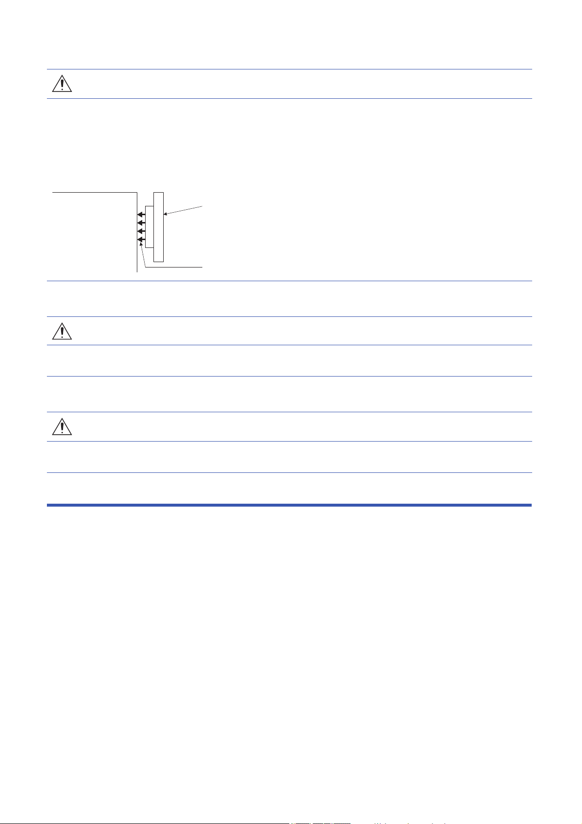
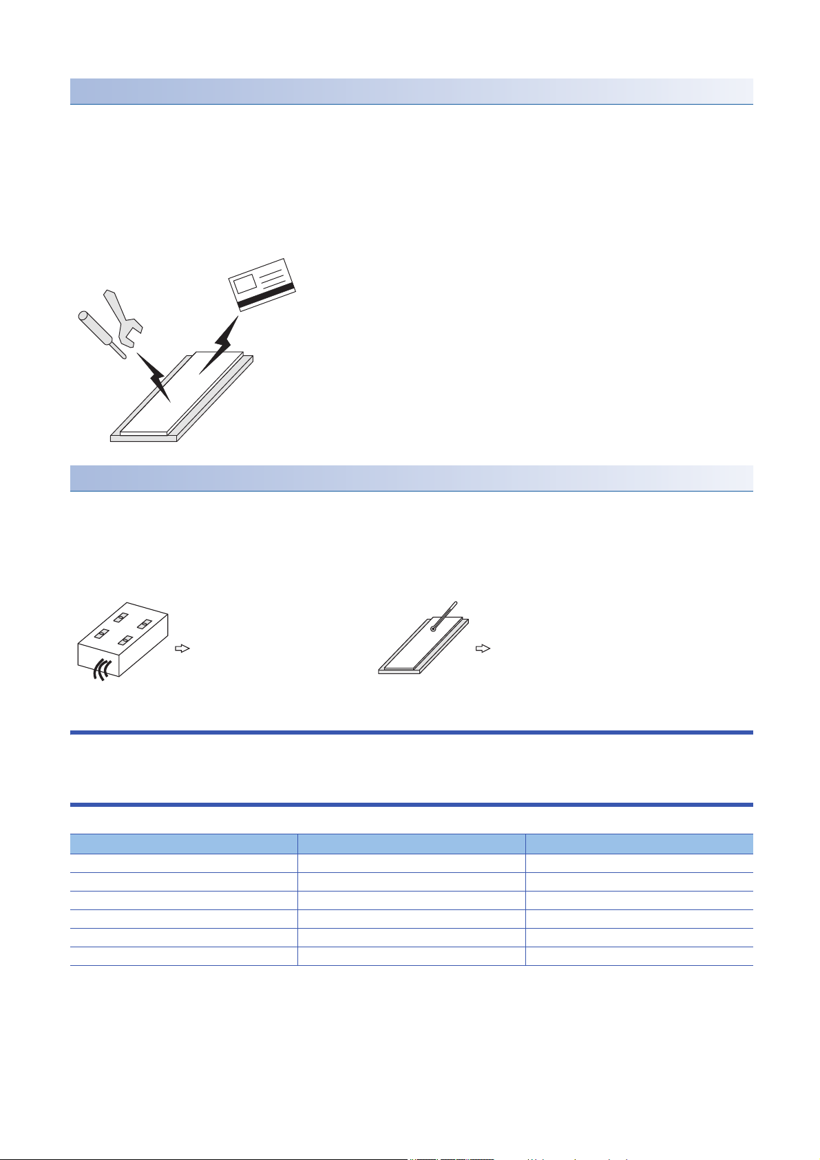
● On linear servo motors, the permanent magnet on the secondary side makes the magnetic bodies
generate attraction force. Due to suction force between the secondary side and the magnetic material
side that may cause injuries to fingers and other body parts, take special care in handling.
Magnetic body
such as iron
Secondary side
Magnetic attraction force: 5 t max.
[Maintenance]
WARNING
● To prevent an electric shock, any person who is involved in inspection should be fully competent to do
the work.
[Disposal]
CAUTION
● To prevent burn injury, do not touch the secondary side after the demagnetization of the secondary
side by heating over 300 ˚C until it becomes cool enough.
DISPOSAL OF WASTE
Please dispose this product and other options according to your local laws and regulations.
2
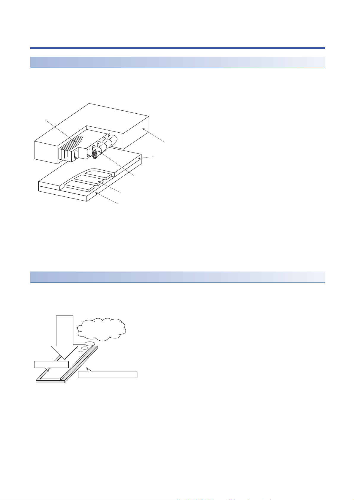
Handling of Linear Servo Motor
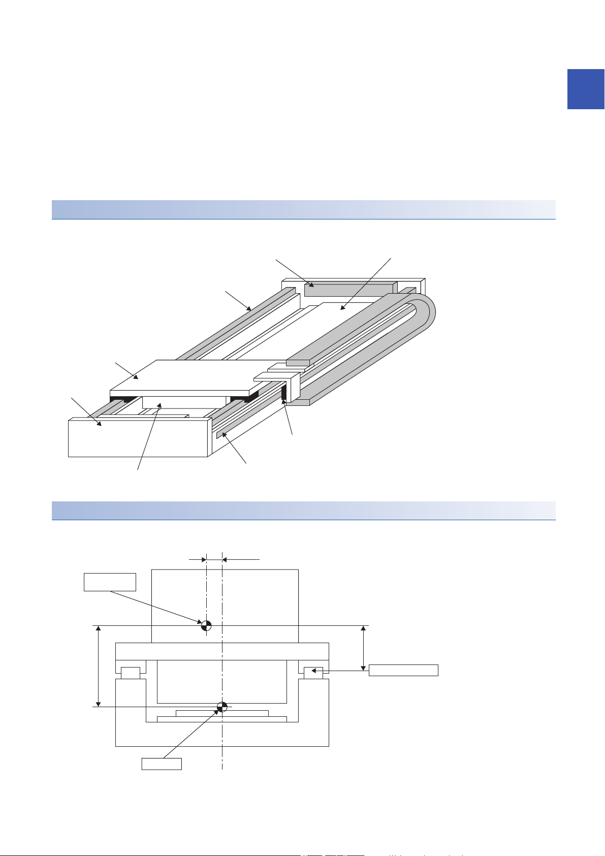
Primary side
Laminated core
Molded resin
Molded resin or stainless cover
Motor coil
Permanent magnet
Mounting part (yoke)
Secondary side
Structure of linear servo motor
Linear servo motor has the primary side which consists of the iron core and coil, and the secondary side which consists of the
mounting part (yoke) and permanent magnet. (excluding coreless type LM-U2P_)
■Primary side
The primary side has the motor core with winding and is covered with the molded resin.
■Secondary side
The secondary side has the permanent magnet on the mounting part (yoke) and is covered with the molded resin or stainless
cover.
Magnetic attraction force
The secondary side of the linear servo motor contains a strong permanent magnet, so a magnetic attraction force (the force
by which a magnet attracts magnetic bodies) is generated toward magnetic bodies such as iron.
This magnetic attraction force is always acting regardless of linear servo motor power on/off.
Always acting
regardless of on/off
of the power
Magnetic attraction
force
Magnet side face
Mounting part (yoke) side face
3
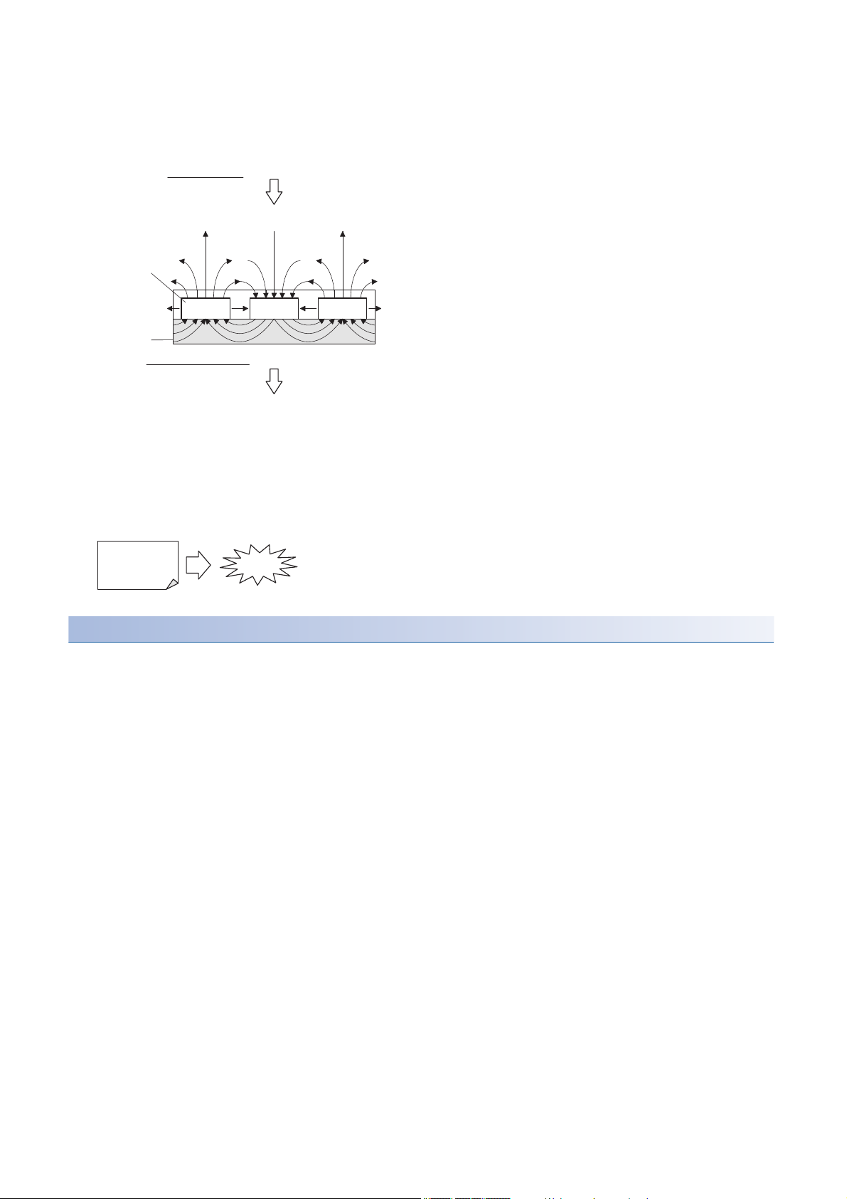
The magnetic fluxes generating from the permanent magnet disperse in the air from the magnet face side (facing the primary
Magnet side face...Dispersion of magnetic fluxes
Generating magnetic attraction force
Magnetic
fluxes
Permanent magnet
North pole South pole North pole
Mounting part side face...No dispersion of magnetic fluxes
Mounting
part (yoke)
Not generating magnetic attraction force
If an A4-size iron sheet is fully attracted
A4
(21 × 29.7 cm)
Approx. 2.5 t
side), and most of them do not leak to the mounting part (yoke) surface side for its structure.
Because of this, a magnetic attraction force occurs on the magnet face side of the secondary side, not on the mounting part
(yoke) surface side.
The permanent magnet used for the linear servo motor is very strong.
When an A4-sized iron sheet is fully attracted, the magnetic attraction force becomes as high as 2.5 t. Use abundance of
caution with the handling.
Magnetic attraction force = 400 [kPa]
For safety
The magnetic attraction force is in inverse proportion to square of the distance to a magnetic body, so it drastically increases
when the distance becomes small.
When mounting the secondary side of linear side motor, ensure the sufficient distance from the magnetic bodies around it and
securely fix those magnetic bodies.
4
Notes on handling
Primary side Secondary side
Discard as industrial waste.
After demagnetizing over 300 °C,
discard as industrial waste.
• Handling must be done by the engineers who have a full knowledge of this product.
• One who uses a medical device like a pacemaker must keep away from the product and equipment.
• Do not wear metals such as watch, pierced earring, necklace, etc.
• Use nonmagnetic tools. (Example) Explosion-proof beryllium copper alloy safety tools: bealon (NGK)
• Do not put magnetic card, watch, portable phone, etc. close to the motor.
• Do not add a shock or a stress on the mold part of the product. (Otherwise, the linear servo motor may be damaged.)
• Put a sign such as "Note a strong magnetic.", and take action by giving cautions to the surrounding, etc.
Disposal of linear servo motor
• The primary side must be discarded as industrial waste.
• The secondary side must be discarded as industrial waste after demagnetization over 300 ˚C.
• When the demagnetization is not possible, pack into a box and return to your local sales office.
• Do not leave the product.
Cables used for wiring
Wires mentioned in this user’s manual are selected based on the ambient temperature of 40 °C.
U.S. CUSTOMARY UNITS
U.S. customary units are not shown in this manual. Convert the values if necessary according to the following table.
Quantity SI (metric) unit U.S. customary unit
Mass 1 [kg] 2.2046 [lb]
Length 1 [mm] 0.03937 [inch]
Torque 1 [N•m] 141.6 [oz•inch]
-4
Moment of inertia 1 [(× 10
Load (thrust load/axial load) 1 [N] 0.2248 [lbf]
Temperature N [°C] × 9/5 + 32 N [°F]
kg•m2)] 5.4675 [oz•inch2]
5

CONTENTS
SAFETY INSTRUCTIONS. . . . . . . . . . . . . . . . . . . . . . . . . . . . . . . . . . . . . . . . . . . . . . . . . . . . . . . . . . . . . . . . . . . .1
DISPOSAL OF WASTE . . . . . . . . . . . . . . . . . . . . . . . . . . . . . . . . . . . . . . . . . . . . . . . . . . . . . . . . . . . . . . . . . . . . . .2
Handling of Linear Servo Motor. . . . . . . . . . . . . . . . . . . . . . . . . . . . . . . . . . . . . . . . . . . . . . . . . . . . . . . . . . . . . . . .3
Cables used for wiring. . . . . . . . . . . . . . . . . . . . . . . . . . . . . . . . . . . . . . . . . . . . . . . . . . . . . . . . . . . . . . . . . . . . . . .5
U.S. CUSTOMARY UNITS . . . . . . . . . . . . . . . . . . . . . . . . . . . . . . . . . . . . . . . . . . . . . . . . . . . . . . . . . . . . . . . . . . .5
CHAPTER 1 Handling of Linear Servo Motor 8
1.1 Design Instructions . . . . . . . . . . . . . . . . . . . . . . . . . . . . . . . . . . . . . . . . . . . . . . . . . . . . . . . . . . . . . . . . . . . . . . . 8
1.2 Instructions on installation operation . . . . . . . . . . . . . . . . . . . . . . . . . . . . . . . . . . . . . . . . . . . . . . . . . . . . . . . 10
1.3 Instructions on storage. . . . . . . . . . . . . . . . . . . . . . . . . . . . . . . . . . . . . . . . . . . . . . . . . . . . . . . . . . . . . . . . . . . 12
Storage method. . . . . . . . . . . . . . . . . . . . . . . . . . . . . . . . . . . . . . . . . . . . . . . . . . . . . . . . . . . . . . . . . . . . . . . . . . 13
1.4 Instructions for disposal. . . . . . . . . . . . . . . . . . . . . . . . . . . . . . . . . . . . . . . . . . . . . . . . . . . . . . . . . . . . . . . . . . 13
CHAPTER 2 INSPECTION 14
2.1 Inspections on primary side (coil) . . . . . . . . . . . . . . . . . . . . . . . . . . . . . . . . . . . . . . . . . . . . . . . . . . . . . . . . . . 14
2.2 Inspections on secondary side (magnet) . . . . . . . . . . . . . . . . . . . . . . . . . . . . . . . . . . . . . . . . . . . . . . . . . . . . 15
2.3 Inspections of linear encoder. . . . . . . . . . . . . . . . . . . . . . . . . . . . . . . . . . . . . . . . . . . . . . . . . . . . . . . . . . . . . . 15
CHAPTER 3 REPLACEMENT OF LINEAR SERVO MOTOR IN THE ABSOLUTE POSI-
TION DETECTION SYSTEM 16
3.1 Replacement of primary side (coil) or secondary side (magnet) . . . . . . . . . . . . . . . . . . . . . . . . . . . . . . . . . 16
3.2 Replacement of linear encoder . . . . . . . . . . . . . . . . . . . . . . . . . . . . . . . . . . . . . . . . . . . . . . . . . . . . . . . . . . . . 16
CHAPTER 4 CONNECTION OF SERVO AMPLIFIER AND LINEAR SERVO MOTOR 18
4.1 Precautions for wiring. . . . . . . . . . . . . . . . . . . . . . . . . . . . . . . . . . . . . . . . . . . . . . . . . . . . . . . . . . . . . . . . . . . . 19
4.2 Power supply cable wiring diagrams . . . . . . . . . . . . . . . . . . . . . . . . . . . . . . . . . . . . . . . . . . . . . . . . . . . . . . . 19
LM-H3/LM-U2/LM-K2 series . . . . . . . . . . . . . . . . . . . . . . . . . . . . . . . . . . . . . . . . . . . . . . . . . . . . . . . . . . . . . . . . 19
LM-F series . . . . . . . . . . . . . . . . . . . . . . . . . . . . . . . . . . . . . . . . . . . . . . . . . . . . . . . . . . . . . . . . . . . . . . . . . . . . . 21
4.3 Selection example of wires. . . . . . . . . . . . . . . . . . . . . . . . . . . . . . . . . . . . . . . . . . . . . . . . . . . . . . . . . . . . . . . . 22
CHAPTER 5 Linear servo motor 23
5.1 Rating plate . . . . . . . . . . . . . . . . . . . . . . . . . . . . . . . . . . . . . . . . . . . . . . . . . . . . . . . . . . . . . . . . . . . . . . . . . . . . 23
5.2 Environment. . . . . . . . . . . . . . . . . . . . . . . . . . . . . . . . . . . . . . . . . . . . . . . . . . . . . . . . . . . . . . . . . . . . . . . . . . . . 25
5.3 LM-H3 series . . . . . . . . . . . . . . . . . . . . . . . . . . . . . . . . . . . . . . . . . . . . . . . . . . . . . . . . . . . . . . . . . . . . . . . . . . . 26
Model designation . . . . . . . . . . . . . . . . . . . . . . . . . . . . . . . . . . . . . . . . . . . . . . . . . . . . . . . . . . . . . . . . . . . . . . . . 26
Combinations of servo amplifiers and linear servo motors . . . . . . . . . . . . . . . . . . . . . . . . . . . . . . . . . . . . . . . . . 27
LM-H3 series specification list . . . . . . . . . . . . . . . . . . . . . . . . . . . . . . . . . . . . . . . . . . . . . . . . . . . . . . . . . . . . . . . 28
Thrust characteristics . . . . . . . . . . . . . . . . . . . . . . . . . . . . . . . . . . . . . . . . . . . . . . . . . . . . . . . . . . . . . . . . . . . . . 29
Installation . . . . . . . . . . . . . . . . . . . . . . . . . . . . . . . . . . . . . . . . . . . . . . . . . . . . . . . . . . . . . . . . . . . . . . . . . . . . . . 31
LM-H3 series primary side (coil) dimensions. . . . . . . . . . . . . . . . . . . . . . . . . . . . . . . . . . . . . . . . . . . . . . . . . . . . 34
LM-H3 series secondary side (magnet) dimensions . . . . . . . . . . . . . . . . . . . . . . . . . . . . . . . . . . . . . . . . . . . . . . 35
5.4 LM-U2 series . . . . . . . . . . . . . . . . . . . . . . . . . . . . . . . . . . . . . . . . . . . . . . . . . . . . . . . . . . . . . . . . . . . . . . . . . . . 37
Model designation . . . . . . . . . . . . . . . . . . . . . . . . . . . . . . . . . . . . . . . . . . . . . . . . . . . . . . . . . . . . . . . . . . . . . . . . 37
Combinations of servo amplifiers and linear servo motors . . . . . . . . . . . . . . . . . . . . . . . . . . . . . . . . . . . . . . . . . 39
LM-U2 series specification list . . . . . . . . . . . . . . . . . . . . . . . . . . . . . . . . . . . . . . . . . . . . . . . . . . . . . . . . . . . . . . . 40
Thrust characteristics . . . . . . . . . . . . . . . . . . . . . . . . . . . . . . . . . . . . . . . . . . . . . . . . . . . . . . . . . . . . . . . . . . . . . 42
Installation . . . . . . . . . . . . . . . . . . . . . . . . . . . . . . . . . . . . . . . . . . . . . . . . . . . . . . . . . . . . . . . . . . . . . . . . . . . . . . 43
6

LM-U2 series primary side (coil) dimensions. . . . . . . . . . . . . . . . . . . . . . . . . . . . . . . . . . . . . . . . . . . . . . . . . . . . 46
LM-U2 series secondary side (magnet) dimensions . . . . . . . . . . . . . . . . . . . . . . . . . . . . . . . . . . . . . . . . . . . . . . 49
5.5 LM-F series. . . . . . . . . . . . . . . . . . . . . . . . . . . . . . . . . . . . . . . . . . . . . . . . . . . . . . . . . . . . . . . . . . . . . . . . . . . . . 51
Model designation . . . . . . . . . . . . . . . . . . . . . . . . . . . . . . . . . . . . . . . . . . . . . . . . . . . . . . . . . . . . . . . . . . . . . . . . 51
Combinations of servo amplifiers and linear servo motors . . . . . . . . . . . . . . . . . . . . . . . . . . . . . . . . . . . . . . . . . 52
LM-F series specification list . . . . . . . . . . . . . . . . . . . . . . . . . . . . . . . . . . . . . . . . . . . . . . . . . . . . . . . . . . . . . . . . 52
Thrust characteristics . . . . . . . . . . . . . . . . . . . . . . . . . . . . . . . . . . . . . . . . . . . . . . . . . . . . . . . . . . . . . . . . . . . . . 53
Installation . . . . . . . . . . . . . . . . . . . . . . . . . . . . . . . . . . . . . . . . . . . . . . . . . . . . . . . . . . . . . . . . . . . . . . . . . . . . . . 54
Liquid cooling. . . . . . . . . . . . . . . . . . . . . . . . . . . . . . . . . . . . . . . . . . . . . . . . . . . . . . . . . . . . . . . . . . . . . . . . . . . . 57
LM-F series primary side (coil) dimensions . . . . . . . . . . . . . . . . . . . . . . . . . . . . . . . . . . . . . . . . . . . . . . . . . . . . . 58
LM-F series secondary side (magnet) dimensions . . . . . . . . . . . . . . . . . . . . . . . . . . . . . . . . . . . . . . . . . . . . . . . 59
5.6 LM-K2 series . . . . . . . . . . . . . . . . . . . . . . . . . . . . . . . . . . . . . . . . . . . . . . . . . . . . . . . . . . . . . . . . . . . . . . . . . . . 60
Model designation . . . . . . . . . . . . . . . . . . . . . . . . . . . . . . . . . . . . . . . . . . . . . . . . . . . . . . . . . . . . . . . . . . . . . . . . 60
Combinations of servo amplifiers and linear servo motors . . . . . . . . . . . . . . . . . . . . . . . . . . . . . . . . . . . . . . . . . 61
LM-K2 series specification list . . . . . . . . . . . . . . . . . . . . . . . . . . . . . . . . . . . . . . . . . . . . . . . . . . . . . . . . . . . . . . . 62
Thrust characteristics . . . . . . . . . . . . . . . . . . . . . . . . . . . . . . . . . . . . . . . . . . . . . . . . . . . . . . . . . . . . . . . . . . . . . 63
Installation . . . . . . . . . . . . . . . . . . . . . . . . . . . . . . . . . . . . . . . . . . . . . . . . . . . . . . . . . . . . . . . . . . . . . . . . . . . . . . 64
LM-K2 series primary side (coil) dimensions. . . . . . . . . . . . . . . . . . . . . . . . . . . . . . . . . . . . . . . . . . . . . . . . . . . . 69
LM-K2 series secondary side (magnet) dimensions . . . . . . . . . . . . . . . . . . . . . . . . . . . . . . . . . . . . . . . . . . . . . . 71
REVISIONS. . . . . . . . . . . . . . . . . . . . . . . . . . . . . . . . . . . . . . . . . . . . . . . . . . . . . . . . . . . . . . . . . . . . . . . . . . . . . .74
WARRANTY . . . . . . . . . . . . . . . . . . . . . . . . . . . . . . . . . . . . . . . . . . . . . . . . . . . . . . . . . . . . . . . . . . . . . . . . . . . . .75
TRADEMARKS . . . . . . . . . . . . . . . . . . . . . . . . . . . . . . . . . . . . . . . . . . . . . . . . . . . . . . . . . . . . . . . . . . . . . . . . . . .76
CONTENTS
7

1 Handling of Linear Servo Motor
Precautions
• MR-J5-_G_-RJ and MR-J5-_A_-RJ will be available in the future.
The linear servo motor uses a strong magnet on the secondary side. Incorrect handling is extremely dangerous and may
cause serious accidents. Please read this chapter and thoroughly understand the contents beforehand, and handle carefully.
1.1 Design Instructions
• Although dynamic brake can be applied by the servo amplifier, the coasting distance becomes longer when the mass of the
moving part is heavy or when the speed is high. This is highly dangerous and may result in collision into the stroke end.
Install anti-collision mechanism such as an air brake, or an electrical and mechanical stopper such as shock absorber to
reduce the impact of the movable part. (No linear servo motor with an electromagnetic brake is available.)
• The magnetic attraction force operating between the primary and secondary sides is always in operation even when the
linear servo motor power is not turned on. As such, the machine must be designed with sufficient rigidity to support the
magnetic attraction force and maintain the accuracy.
• Since the running load by friction increases in proportion to the magnetic attraction force, arrange to reduce friction as
much as possible, such as installing the linear guide with high accuracy.
• When the linear servo motor is used on a vertical axis, a drop prevention system such as a spring and counter balance is
required on the machine side.
• Install the linear servo motor in such a way for the thrust to operates on the center of gravity of the moving part. When the
thrust does not operates on the center of gravity of the moving part, the moment occurs.
• If magnetic chips such as iron fragments or the like is present, it may stick to the permanent magnet on the secondary side
and cause malfunction. In such environment, take measures to prevent adsorption and penetration of magnetic chips.
• Oil proof and dust proof measures for the linear encoder is required, more so than for the linear servo motor. Contact each
linear encoder manufacturer for details.
• Do not hit the primary side against the stopper. The primary side may be damaged. Arrange for the table attached to the
primary side to hit the stopper.
• Do not use the screw holes of the linear servo motor for any purposes, other than for machine installation.
• For installation, use all the screw holes provided in the linear servo motor.
• When a dangerous condition is presumed at the time of stoppage and product failure, prevent it by providing an external
braking system for maintenance use.
• Provide an adequate protection to prevent unexpected restart after an instantaneous power failure.
• Arrange for the primary and secondary side to satisfy the mounting dimensions.
• When using linear guide as base, check the specifications, and determine the processing accuracy. Contact each linear
guide manufacturer for details.
• Movable range of the linear servo motor should be equal to or less than the effective measurement length of the linear
encoder.
• For the stopper, use shock-absorbing material such as polyurethane rubber.
• In the condition where cutting fluid or lubricating oil are c
humidity, continuous operation of the linear servo motor for a long period of time may results in the deterioration on the
insulation of the linear servo motor. Provide measures such as oil proof, dust proof cover, and dew condensation prevention
to protect the linear servo motor.
• Arrange in consideration the installation work. For details of the installation, refer to the following and the "Installation"
section of each linear servo motor series.
Page 10 Instructions on installation operation
• For high-accuracy positioning, ensure that the machine to be as rigid as possible, and increase the mechanical resonance
point.
• To ensure the utmost rigidity of the machines, adopt an integrated structure to the base. When using bolts, etc. as fastener
is inevitable, use thick bolt with shorter neck size. Make the pitch dimension of bolt holes as small as possible.
onstantly applied, and condensation occurs due to excessive
8
1 Handling of Linear Servo Motor
1.1 Design Instructions
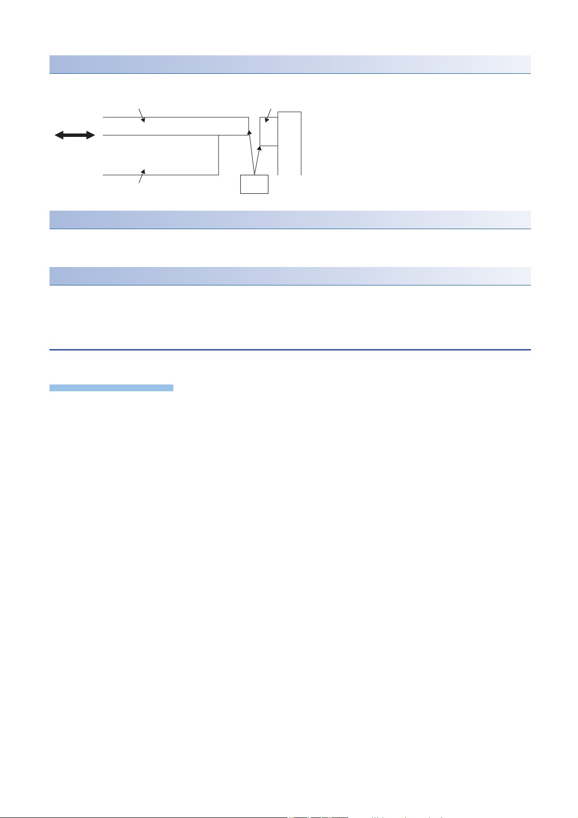
• Make the moving parts as light as possible, and make the base parts heavier and sturdier.
Linear servo motor secondary side
Stopper
Linear guide
Table
Base
Linear encoder head
Linear encoder scale
Linear servo motor primary side
As short as possible
Gravity center
of moving part
As short as possible
As short as
possible
Linear guide center
Thrust center
• When loading works or others on the table, make the center of gravity to be as low as possible. Additionally, position of the
center of gravity should be between the two linear guides.
• Since the movement and accuracy of the machine may be adversely affected, arrange for the center of thrust of the linear
servo motor, and the center of gravity of the moving object, to be closer with one another.
• When the mounting rigidity of the linear encoder is not enough, the feedback signal may be disturbed by the machine
vibration, and the desired performance may not be satisfied. Furthermore, as the same condition also applies when the
linear encoder is susceptible to electric noise, arrange and install in such a way that would be unaffected by vibration and
electric noise.
• Establish a structure that can withstand high speed and high acceleration/deceleration.
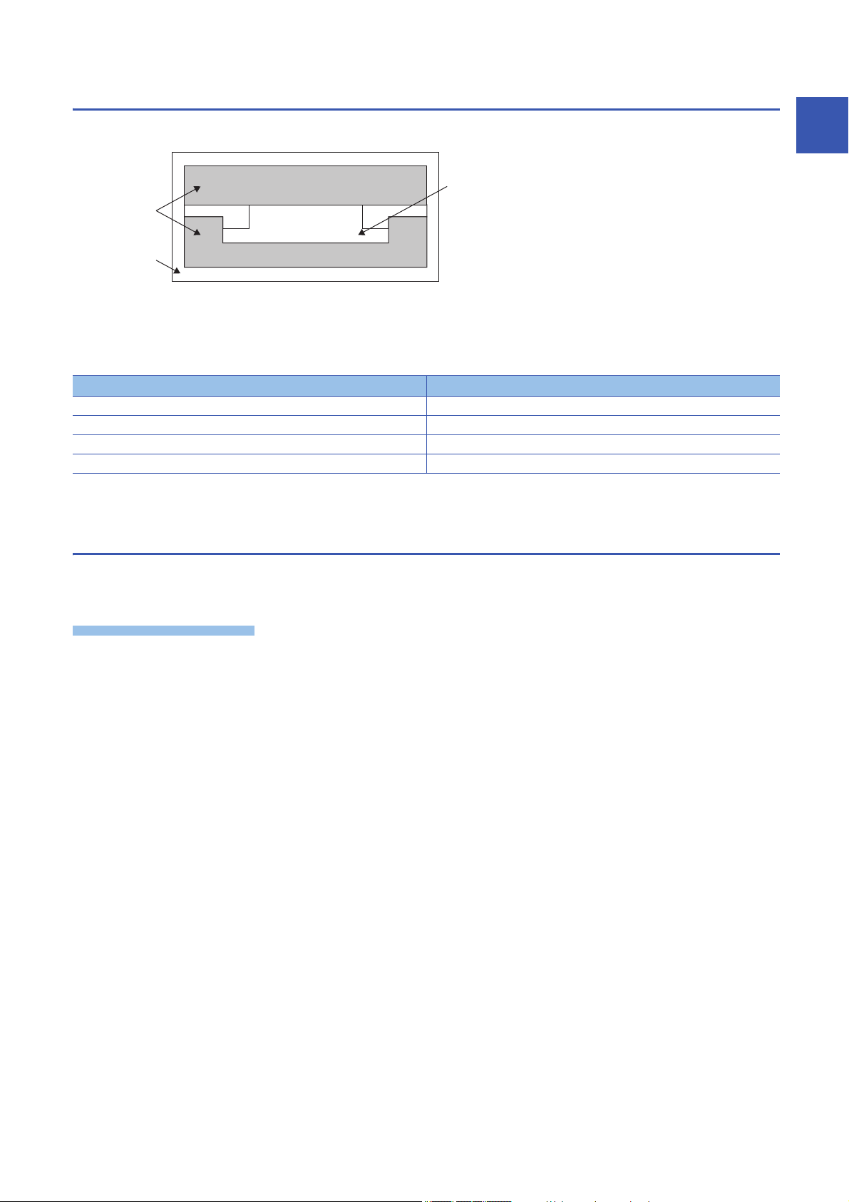
Basic structure of linear servo motor incorporated slider
The following diagram shows an example of the basic structure of linear slider.
1
Instructions on the structure of linear slider
Instructions on the structure of linear slider are shown on the following diagram.
1 Handling of Linear Servo Motor
1.1 Design Instructions
9
Stopper
Precautions
Stopper
Table
Contact
surface
Primary side
As shown in the following figure, arrange for the table attached to the primary side to hit the stopper.
LINEAR ENCODER
Oil proof and dust proof measures for the linear encoder is required, more so than for the linear servo motor.
Contact each linear encoder manufacturer for details.
Linear guide
Install the linear guide with high accuracy.
Contact each linear guide manufacturer for details.
1.2 Instructions on installation operation
Instructions on using lifting machines such as crane when installing the linear servo motor are shown below.
• The cables should not be damaged, stressed, loaded, or pinched.
• Install the linear servo motor on incombustible material. Installing them directly or close to combustibles will lead to smoke
or a fire.
• Prevent contaminants such as conductive foreign objects such as screws and metal pieces, and combustible foreign object
such as oil, from entering the linear servo motor.
• Linear servo motor may be hot depending on the operating method. Take safety measures such as providing covers.
• Workers installing linear servo motors and machine operators are not allowed to wear or carry electronic devices (such as
watches, calculators, personal computers), and magnetic recording media (IC cards, magnetic cards, floppy disks, and
others), closer to the secondary side. The magnetic effect may cause operation failure or malfunction.
• Securely fix the linear servo motor to the machine. If attached insecurely, the motor may come off during operation.
• Do not overtighten the eyebolts of the linear servo motor. Tightening too hard may damage the tap.
• Stacking in excess of the specified number of product packages is not allowed.
• Do not hold the cables or connectors when carrying the linear servo motor. Otherwise, it may drop.
• Install the linear servo motor in a place that can withstand the mass, in accordance with the user’s manual.
• When installing on the secondary side, use non-magnetic tools.
• Securely fix the linear servo motor to the machine. If attached insecurely, the motor may come off during operation.
• The moving direction of the linear servo motor and linear encoder must match. Otherwise, the linear servo motor may
operate unexpectedly.
• To prevent a connection failure, malfunction, or others, do not strike the connector.
• Use the product within the specified environment. For the environment conditions, refer to the specifications of the linear
servo motor series.
• To prevent rust, do not touch the linear servo motor with bare hands.
• The primary side and secondary side may be damaged by a fall or shock.
• Do not install and operate the servo amplifier and the linear servo motor which have been damaged, or with any parts
• The permanent magnet on the secondary side of the linear servo motor has a suction force against magnetic parts.
missing.
Therefore, people who are using medical device such as a pacemaker must check with the medical device manufacturer
10
1 Handling of Linear Servo Motor
1.2 Instructions on installation operation
whether they can work in such environment.
• On the packing condition (cardboard) shipped from our company, although the magnet on the secondary side does not
have any serious impact on the outside, do not place the magnetic parts (including the primary side, other secondary side,
and tools) close to the secondary side until the linear servo motor is assembled to the machine. Be cautious in the
workplace and its surroundings.
• For installation of the linear servo motor and working near the linear servo motor, use non-magnetic tools. They are
necessary to ensure safety and improve workability. Especially when installing the primary side after the installation of the
secondary side. For screws to be used, refer to the dimensions of each linear servo motor series.
• Do not get on or put heavy load on the equipment.
• Do not drop or strike the linear servo motor.
• To prevent a fire or injury from occurring in case of an earthquake or other natural disasters, securely install, mount, and
wire the linear servo motor in accordance with the user’s manual.
• To prevent an electric shock or a fire, do not disassemble, repair, or modify the product. Disassembled, repaired, and/or
modified products are not covered under warranty.
• Keep the cumulative pitch error of the mounting screw holes to within ±0.2 mm (0.1 mm for LM-K2 series). When two or
more secondary sides are installed, clearance may be left between the secondary sides depending on the installing method
and the number of secondary sides.
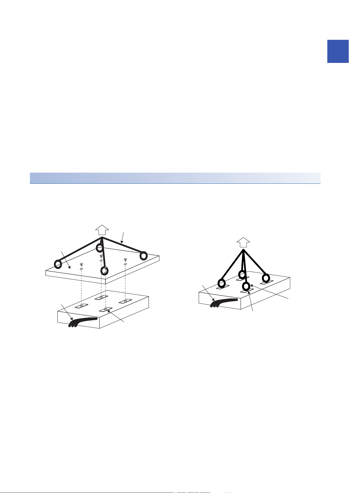
Primary side (coil)
For lifting the primary side, lift the tool for lifting attached to the primary side or lift the eyebolt attached to the screw hole for
primary-side mounting as shown in the following diagram.
When lifting, do not add any stress on the mold part and the power supply cable by the wire, and the like.
Set the lifting points on both longitudinal ends (two or more).
1
Tool for lifting
Power cable or others
Wire or others
Wire or others
Power cable or others
Eyebolt
Screw hole for primary-side mounting
Screw hole for primary-side mounting
When using the tool for lifting When using the eyebolts
1 Handling of Linear Servo Motor
1.2 Instructions on installation operation
11
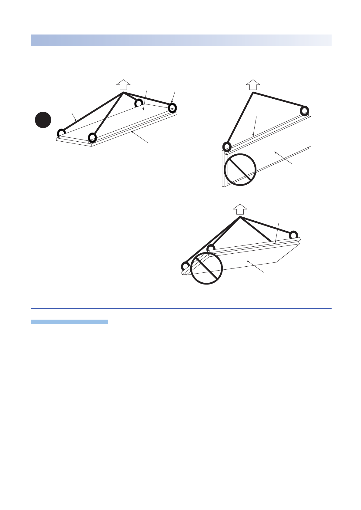
Secondary side (magnet)
Precautions
Magnet side face
Eyebolt
Wire or others
Mounting part (yoke)
side face
Mounting part (yoke) side face
Magnet side face
Mounting part (yoke) side face
Magnet side face
As shown in the following diagram, for lifting the secondary side, attach eyebolts to the secondary side mounting screw hole.
When lifting the secondary side, to avoid the danger due to the magnetic attraction force, make the magnet face side upward,
and set the lifting points in four or more points.
1.3 Instructions on storage
Note the following when storing the linear servo motor for an extended period of time (guideline: three months or longer).
• Always store the linear servo motor indoors, in a clean and dry place.
• When storing in a dusty and humid area, take measures such as covering the whole product.
• Although the linear servo motor has been rust-proofed with paint and rust prevention oil before shipment, rust may appear
if the linear servo motor is stored in bad conditions for an extended period of time. When storing the linear servo motor for
longer than six months, apply rust prevention oil again to the machine processing surfaces such as the rotor rotating part.
• When the product has been stored for an extended period of time, contact your local sales office.
• Be sure to follow the storage conditions (ambient temperature and humidity, etc.).
• Store the product in the environment with no exposure to rain water, dust, oil, and chemical materials adhesion.
• Do not shock the servo amplifier or linear servo motor.
12
1 Handling of Linear Servo Motor
1.3 Instructions on storage
Storage method
Precautions
Product
Shock-absorbing
material
Package
• Correctly store the linear servo motor in the package.
• When storing the secondary side, put a display such as "Handle with care - Strong magnetic field" on the package or
storage shelf, and also take measures in drawing attention to the surrounding.
• Do not use the deformed packaging box.
• Store the equipment under the following environment.
Item Environment
Ambient temperature -15 ˚C to 70 ˚C (non-freezing)
Ambient humidity 10 %RH to 90 %RH (non-condensing)
Ambience Indoors (no direct sunlight); no corrosive gas, inflammable gas, oil mist or dust
Vibration resistance 49 m/s
• When lifting the product using a suspender, do not apply shock and stress on the mold part.
2
1.4 Instructions for disposal
1
Demagnetize the secondary side by heating over 300 ˚C, and dispose the linear servo motor in accordance with the Law for
Promotion of Effective Utilization of Resources.
• The servo amplifier and the primary side of the linear servo motor must be disposed in accordance with "DISPOSAL OF
WASTE".
• Since the secondary side of the linear servo motor uses the permanent magnet, demagnetize the entire secondary side by
heating over 300 ˚C, then dispose in accordance with "DISPOSAL OF WASTE".
• The permanent magnet on the secondary side of the linear servo motor has a suction force against magnetic parts.
Therefore, people who are using medical device such as a pacemaker must check with the medical device manufacturer
whether they can work in such environment.
• Use caution during and after disassembly, prior to demagnetizing the magnetic force on the secondary side.
• When disassembling and disposing the linear servo motor, do not place the magnetic parts (including the primary side,
other secondary side, and tools) closer to the secondary side.
• Use non-magnetic tools to disassemble and dispose the linear servo motor, or when working near the motor. They are
necessary to ensure safety and improve workability.
1 Handling of Linear Servo Motor
1.4 Instructions for disposal
13

2 INSPECTION
Precautions
The linear servo motor functions as motor when mounted in the equipment (built-in). The IP rating is IP00. Perform the
following inspections and cleaning.
• The linear servo motor is structurally unrepairable. If the linear servo motor is damaged, it must be replaced.
• Do not disassemble and/or repair the equipment on customer side.
• Discoloration of the molded resin of the linear servo motor may occurs. Though the lost color may not be the cause of
malfunction, inspect the molded resin.
• If the magnet protective cover is stainless, it may be deformed or damaged if it is strongly pressed or a magnetic body is
attached to it. Take special care of the end part of the product, as it is easily deformed.
2.1 Inspections on primary side (coil)
Attachment of water and oil
Check that the primary and secondary side of the linear servo motor are not wet with water or oil. When the linear servo motor
is wet, the insulation on the primary side deteriorates, and may cause a malfunction. Establish the mechanical structure in
which water and oil are not attached to the linear servo motor.
Molded resin
Check the molded resin on the primary side for fragmentations, breakages, and cracks. If fragmentations, breakages, and
cracks are found, replace the primary side, as insulation have deteriorated and may cause a malfunction.
Scratches on the surface that faces the secondary side (magnet)
Check for scratches on the primary-side surface which faces the secondary side. If there are scratches on the primary-side
surface which faces the secondary side, replace the primary side. If scratches appear on the primary side due to a foreign
matter caught in the empty clearance between the primary and secondary side, remove the foreign matter, and establish a
mechanical structure to prevent similar situation.
Looseness of mounting screws
Check for loose mounting screws on the primary side. When the mounting screws on the primary side are loose, tighten the
applicable screws.
Scratches and cracks on the linear servo motor cables
Check for scratches and cracks on the linear servo motor cables. If the linear servo motor cables have any scratches or
cracks, replace the applicable cables. Especially when the cables are moved, make inspections periodically.
14
2 INSPECTION
2.1 Inspections on primary side (coil)

2.2 Inspections on secondary side (magnet)
Attachment of water and oil
Check that the primary and secondary side of the linear servo motor are not wet with water or oil. When the linear servo motor
is wet, the insulation on the primary side deteriorates, and may cause a malfunction. Establish the mechanical structure in
which water and oil are not attached to the linear servo motor.
Exposure and levitation of magnet
Check for the exposure and levitation of the magnet on the secondary side. If the magnet on the secondary side is exposed or
levitated, replace the secondary side immediately.
Magnet protective cover
The secondary side surface is covered with the mold resin or stainless cover to protect the magnet.
• When a foreign matter such as dust is attached to the surface, wipe gently with acetone soaked cloth.
• Check the molded resin on the secondary side for fragmentations, breakages, and cracks. If fragmentations, breakages,
and cracks are found, replace the secondary side.
• Check for scratches on the molded resin of the secondary side. When the magnet is exposed by the scratches on the
molded resin of the secondary side, replace the secondary side. If scratches appear on the secondary side due to a foreign
matter caught in the empty clearance between the primary and secondary side, remove the foreign matter, and establish a
mechanical structure to prevent similar situation.
2
Looseness of mounting screws
Check for loose mounting screws on the secondary side. When the mounting screws on the secondary side are loose, tighten
the applicable screws.
2.3 Inspections of linear encoder
The inspections of the linear encoder may be required. For the inspections of the linear encoder, contact the linear encoder
manufacturer.
2 INSPECTION
2.2 Inspections on secondary side (magnet)
15
3 REPLACEMENT OF LINEAR SERVO MOTOR IN
1)
THE ABSOLUTE POSITION DETECTION
SYSTEM
3.1 Replacement of primary side (coil) or secondary
side (magnet)
After replacing the primary side or the secondary side, carry out the magnetic pole detection again.
3.2 Replacement of linear encoder
After replacing the linear encoder, carry out the magnetic pole detection and homing.
Checking method of the mounting position of linear encoder
1. Before replacing the linear encoder, check the encoder information using MR Configurator2, with the linear servo motor
fixed at the specified position.
2. Replace the linear encoder with a position gap before and after the replacement at ± 0.1 mm.
3. After replacing the linear encoder, check the encoder information using MR Configurator2, with the linear servo motor
fixed at the specified position again.
4. Confirm that the value converted from the difference of the encoder information (resolution unit), before and after
replacement of the linear encoder, is ± 0.1 mm or less.
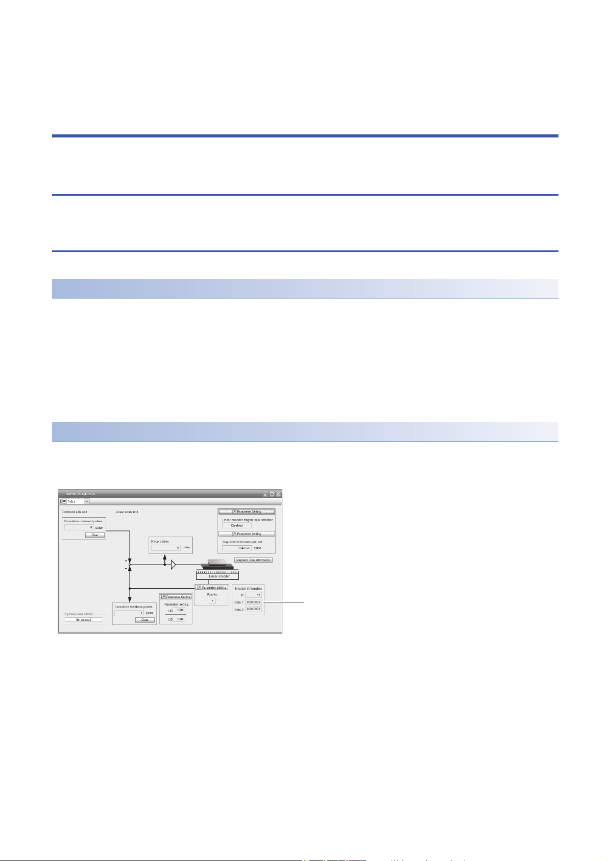
Reading method of encoder information by using MR Configurator2
1. Check that the personal computer is connected with the servo amplifier, and select "Diagnosis" and then select "Linear
diagnosis". The following window appears.
2. Reading the encoder information data 1)
16
3 REPLACEMENT OF LINEAR SERVO MOTOR IN THE ABSOLUTE POSITION DETECTION SYSTEM
3.1 Replacement of primary side (coil) or secondary side (magnet)

MEMO
3
3 REPLACEMENT OF LINEAR SERVO MOTOR IN THE ABSOLUTE POSITION DETECTION SYSTEM
3.2 Replacement of linear encoder
17
4 CONNECTION OF SERVO AMPLIFIER AND
Precautions
U
M
V
W
U
V
W
U
M
V
W
U
V
W
Linear servo motor Linear servo motorServo amplifier Servo amplifier
LINEAR SERVO MOTOR
• Insulate the conductive parts of the terminals.
• The performance is not guaranteed if the specified servo amplifier and linear servo motor are not combined. If used with
unspecified combination, the servo amplifier or linear servo motor may be damaged or may operate unexpectedly.
• The equipment must be installed in the specified direction.
• Do not install or operate the linear servo motor which has been damaged or has any parts missing.
• Do not modify the linear servo motor.
• To prevent unexpected operation of the linear servo motor, wire the equipment correctly and securely.
• Make sure to connect the cables and connectors by using the fixing screws and the locking mechanism. Otherwise, the
cables and connectors may be disconnected during operation.
• Do not install a power capacitor, surge killer, or radio noise filter (optional FR-BIF(-H)) on the servo amplifier output side.
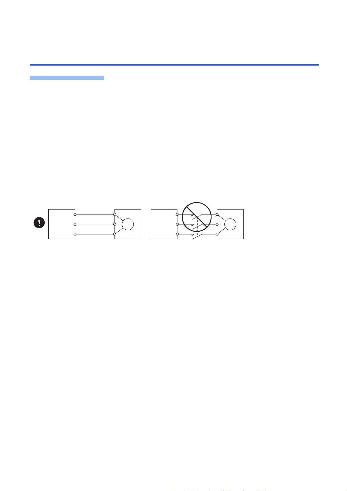
• To avoid a malfunction, connect the wires to the correct phase terminals (U/V/W) of the servo amplifier and the linear servo
motor.
• To prevent abnormal operation and malfunction, connect the servo amplifier power output (U/V/W) to the linear servo motor
power input (U/V/W) directly. Do not connect a magnetic contactor and others between them.
• To prevent a malfunction, do not connect AC power supply directly to the linear servo motor.
• When the wires are not tightened enough to the terminal block, the wires or terminal block may generate heat because of
the poor contact. Be sure to tighten the wires with specified torque.
• The cables such as the power cable deriving from the primary side cannot stand the long-term bending action. Avoid the
bending action by fixing the cables to the moving part or others. Also, use the cable that can withstand the long-term
bending action for the wiring to the servo amplifier.
• Use the linear servo motor with the specified servo amplifier.
• To prevent malfunction, eliminate static electricity before wiring, switch operation, or others.
• To prevent failure and malfunction, only the power/signal specified in the user’s manual should be connected to each
terminal.
• We recommend using HIV wires to connect the servo amplifier to the linear servo motor. Therefore, the recommended wire
sizes may be different from those of the used wires for the previous linear servo motors.
18
4 CONNECTION OF SERVO AMPLIFIER AND LINEAR SERVO MOTOR
4.1 Precautions for wiring
Precautions
*1
Cabinet
Servo
amplifier
Linear servo motor
Protective
earth (PE)
terminal
*2
THM
SCALE
CN2
CN2
THM1
THM2
5
6
U
V
W
MR-J4THCBL03M
30 m or less
Branch cable
*4
Servo amplifier
Lead wire (Linear servo
motor accessory)
*1
Linear servo motor
To linear
encoder
G1 (black) *3
G2 (black) *3
U (black)
Primary side
V (black)
W (black)
E (green/yellow)
Round crimp terminal
• To avoid a malfunction, connect the wires to the correct phase terminals (U/V/W) of the servo amplifier and the linear servo
motor.
• To prevent a malfunction, do not connect AC power supply directly to the linear servo motor.
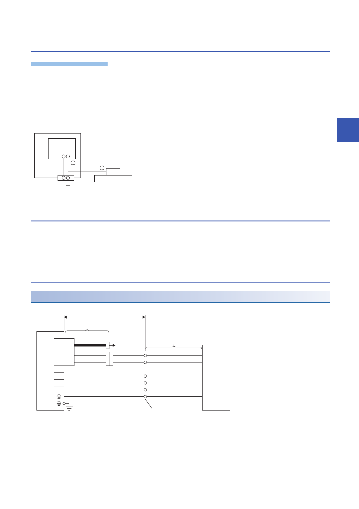
For grounding, connect the grounding lead wire from the servo motor to the protective earth (PE) terminal of the servo
amplifier, and then connect the wire from the servo amplifier to the ground via the protective earth of the cabinet. Do not
connect the wire directly to the protective earth (PE) terminal of the cabinet.
*1 The number of protective earth (PE) terminals of the servo amplifier differs depending on the type of servo amplifier.
4.2 Power supply cable wiring diagrams
4
To wire to the servo amplifier, use connectors packed with the servo amplifier or optional connectors.
For connectors, refer to "Wiring CNP1, CNP2, and CNP3" in the following manual.
MR-J5 User's Manual (Hardware)
Refer to the following for the wires used for wiring.
Page 22 Selection example of wires
LM-H3/LM-U2/LM-K2 series
Connection with MR-J5-_ servo amplifier
*1 The signal names (U/V/W/E/G1/G2) are attached on lead wires.
*2 There is no polarity for the thermistor (G1/G2).
*3 The color is blue for LM-H3 series.
*4 When the branch cable is not used, refer to the following manual.
MR-J5 Partner's Encoder User's Manual
4 CONNECTION OF SERVO AMPLIFIER AND LINEAR SERVO MOTOR
4.1 Precautions for wiring
19
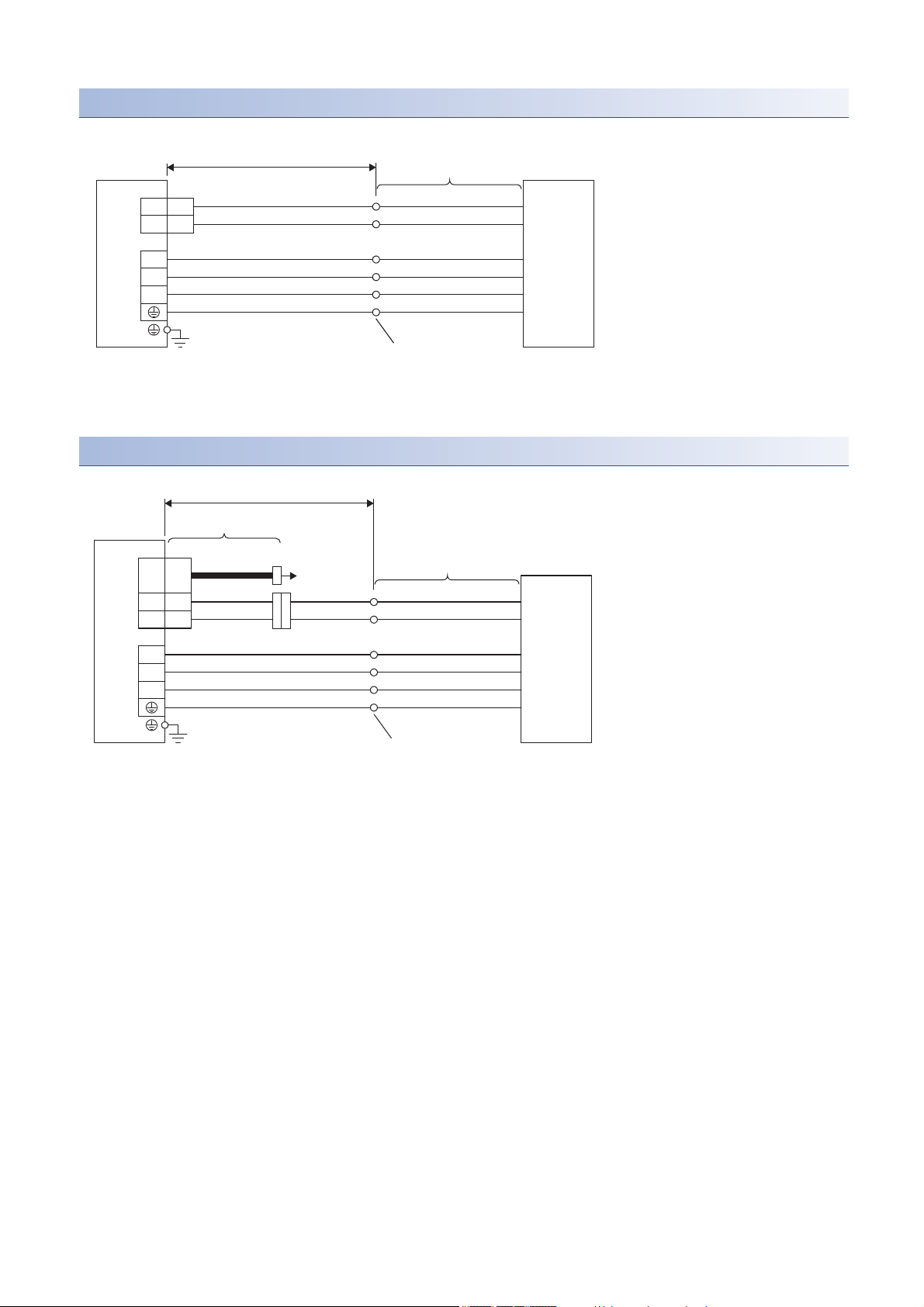
Connection with MR-J5-_-RJ servo amplifier
5
6
THM1
THM2
U
V
W
CN2
*2
Lead wire (Linear servo
motor accessory)
*1
30 m or less
Linear servo motor
Servo amplifier
G1 (black)
*3
G2 (black)
*3
U (black)
Primary side
V (black)
W (black)
E (green/yellow)
Round crimp terminal
THM
SCALE
CN2
5
6
U
V
W
THM1
THM2
CN2A/CN2B/CN2C
CNP3A/CNP3B/CNP3C
*2
MR-J4THCBL03M
30 m or less
Branch cable
*4
Servo amplifier
Lead wire (Linear servo
motor accessory)
*1
Linear servo motor
To linear
encoder
G1 (black)
*3
G2 (black)
*3
U (black)
Primary side
V (black)
W (black)
E (green/yellow)
Round crimp terminal
*1 The signal names (U/V/W/E/G1/G2) are attached on lead wires.
*2 There is no polarity for the thermistor (G1/G2).
*3 The color is blue for LM-H3 series.
Connection with MR-J5W_ servo amplifier
20
*1 The signal names (U/V/W/E/G1/G2) are attached on lead wires.
*2 There is no polarity for the thermistor (G1/G2).
*3 The color is blue for LM-H3 series.
*4 When the branch cable is not used, refer to the following manual.
MR-J5 Partner's Encoder User's Manual
4 CONNECTION OF SERVO AMPLIFIER AND LINEAR SERVO MOTOR
4.2 Power supply cable wiring diagrams
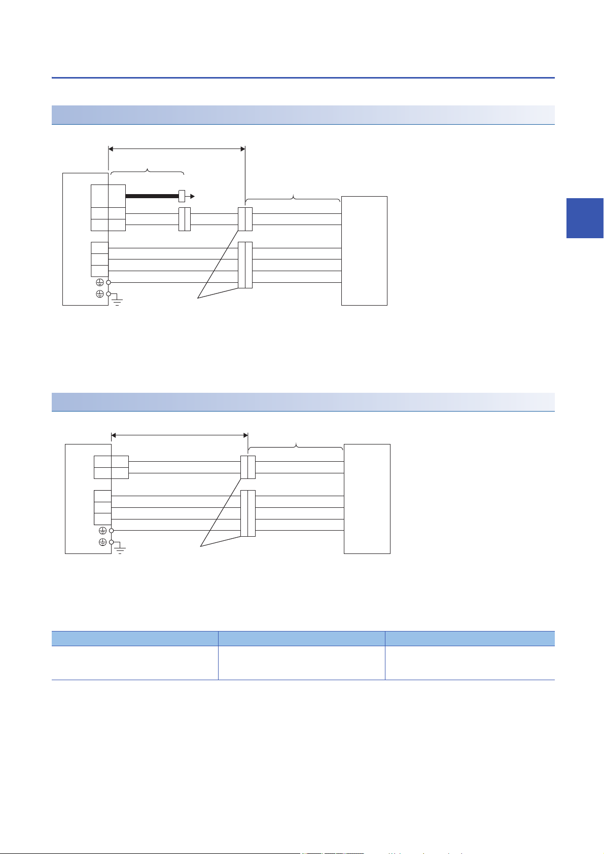
LM-F series
*1
THM
SCALE
CN2
5
6
U
V
W
CN2
U
V
W
E
G1
G2
THM1
THM2
MR-J4THCBL03M
30 m or less
Branch cable
*2
Servo amplifier
Cable (Linear servo
motor accessory)
Linear servo motor
To linear
encoder
Primary side
Junction connector
*3
5
6
U
V
W
CN2
U
V
W
E
G1
G2
*1
THM1
THM2
30 m or less
Cable (Linear servo
motor accessory)
Linear servo motor
Servo amplifier
Primary side
Junction connector
*2
Junction connectors should be prepared by the customer.
Connection with MR-J5-_ servo amplifier
*1 There is no polarity for the thermistor (G1/G2).
*2 When the branch cable is not used, refer to the following manual.
MR-J5 Partner's Encoder User's Manual
*3 Refer to the following.
Page 21 Junction connector
4
Connection with MR-J5-_-RJ servo amplifier
*1 There is no polarity for the thermistor (G1/G2).
*2 Refer to the following.
Page 21 Junction connector
■Junction connector
Linear servo motor primary side Connector for power supply Thermistor connector
LM-FP2B-06M-1SS0 Cable receptacle: D/MS3101A18-10S
Cable clamp: D/MS3057-10A
(DDK)
4 CONNECTION OF SERVO AMPLIFIER AND LINEAR SERVO MOTOR
Cable receptacle: D/MS3101A14S-9S
Cable clamp: D/MS3057-6A
(DDK)
4.2 Power supply cable wiring diagrams
21

4.3 Selection example of wires
Selection conditions of wire size are as follows.
• Construction condition: Single wire set in midair
• Wiring length: 30 m or shorter
Refer to the following when using LM-F series linear servo motor.
Wire size selection example 2 (HIV wire)
Wire size selection examples for HIV wires are indicated below.
Example of selecting the wire sizes
■Wire size selection example 1 (HIV wire)
Linear servo motor (primary side) Wire [mm2]
For power/grounding (U/V/W/E) For thermistor (G1/G2)
LM-H3P2A-07P-BSS0 1.25 (AWG 16) 0.2 (AWG 24)
LM-H3P3A-12P-CSS0
LM-H3P3B-24P-CSS0
LM-H3P3C-36P-CSS0
LM-H3P3D-48P-CSS0 2 (AWG 14)
LM-H3P7A-24P-ASS0 1.25 (AWG 16)
LM-H3P7B-48P-ASS0 2 (AWG 14)
LM-H3P7C-72P-ASS0 2 (AWG 14)
LM-H3P7D-96P-ASS0 3.5 (AWG 12)
LM-U2PAB-05M-0SS0 1.25 (AWG 16)
LM-U2PAD-10M-0SS0
LM-U2PAF-15M-0SS0
LM-U2PBB-07M-1SS0
LM-U2PBD-15M-1SS0
LM-U2PBF-22M-1SS0
LM-U2P2B-40M-2SS0 2 (AWG 14)
LM-U2P2C-60M-2SS0 3.5 (AWG 12)
LM-K2P1A-01M-2SS1 1.25 (AWG 16)
LM-K2P1C-03M-2SS1 2 (AWG 14)
LM-K2P2A-02M-1SS1 1.25 (AWG 16)
LM-K2P2C-07M-1SS1 3.5 (AWG 12)
LM-K2P3C-14M-1SS1 3.5 (AWG 12)
■Wire size selection example 2 (HIV wire)
LM-F series linear servo motor (primary side) Wire [mm2]
For power/grounding (U/V/W/E)For thermistor (G1/G2)
LM-FP2B-06M-1SS0 Natural cooling 2 (AWG 14) 0.2 (AWG 24)
Liquid cooling
22
4 CONNECTION OF SERVO AMPLIFIER AND LINEAR SERVO MOTOR
4.3 Selection example of wires
 Loading...