

Mitsubishi LM-H3S20-384-BSS0, LM-H3P2A-07P-BSS0, LM-H3S20-288-BSS0, LM-H3S30-288-CSS0, LM-H3S20-768-BSS0l User Manual
...
Linear Servo Motor
Mitsubishi Electric AC Servo System
User's Manual
-LM-H3
-LM-U2
-LM-F
-LM-K2

SAFETY INSTRUCTIONS
WARNING
Indicates that incorrect handling may cause hazardous conditions, resulting in
death or severe injury.
CAUTION
Indicates that incorrect handling may cause hazardous conditions, resulting in
medium or slight injury.
Indicates what must not be done. For example, "No Fire" is indicated by .
Indicates what must be done. For example, grounding is indicated by .
(Please read the instructions carefully before using the equipment.)
To use the equipment correctly, do not attempt to install, operate, maintain, or inspect the equipment until you have read
through this manual, Installation guide, and appended documents carefully. Do not use the equipment until you have a full
knowledge of the equipment, safety information and instructions.
In this manual, the safety instruction levels are classified into "WARNING" and "CAUTION".
Note that the CAUTION level may lead to a serious consequence depending on conditions.
Please follow the instructions of both levels because they are important to personnel safety.
What must not be done and what must be done are indicated by the following diagrammatic symbols.
In this manual, instructions at a lower level than the above, instructions for other functions, and so on are classified into
"POINT".
After reading this guide, keep it accessible to the operator.
[Installation/wiring]
WARNING
● To prevent an electric shock, turn off the power and wait for 15 minutes or more before starting wiring
and/or inspection.
● To prevent an electric shock, ground the linear servo motor securely.
● To prevent an electric shock, any person who is involved in wiring should be fully competent to do the
work.
● To prevent an electric shock, do not attempt to wire the linear servo motor until it has been mounted.
● To prevent an electric shock, do not touch the linear servo motor with wet hands.
● To prevent an electric shock, do not touch the conductive parts.
1
[Installation/wiring]
CAUTION
● To prevent injury, transport the products correctly according to their mass.
● To prevent injury, do not touch the sharp edges of the linear servo motor with bare hands when
handling the linear servo motor.
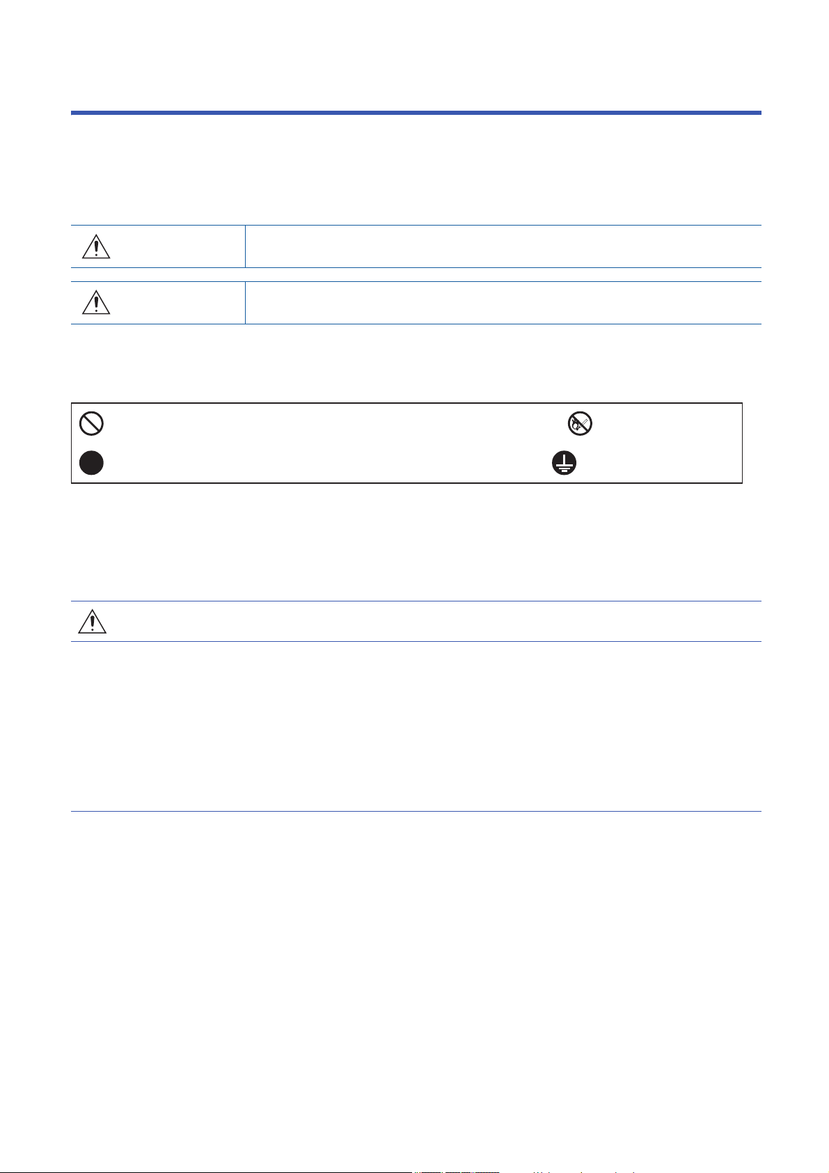
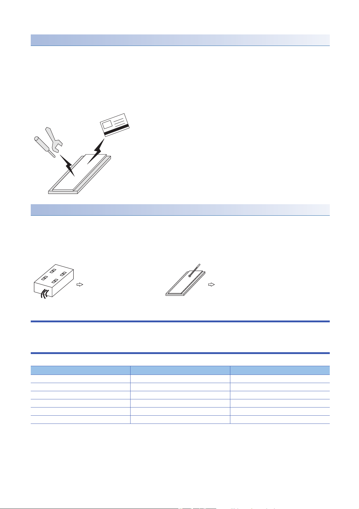
● On linear servo motors, the permanent magnet on the secondary side makes the magnetic bodies
generate attraction force. Due to suction force between the secondary side and the magnetic material
side that may cause injuries to fingers and other body parts, take special care in handling.
Magnetic body
such as iron
Secondary side
Magnetic attraction force: 5 t max.
[Maintenance]
WARNING
● To prevent an electric shock, any person who is involved in inspection should be fully competent to do
the work.
[Disposal]
CAUTION
● To prevent burn injury, do not touch the secondary side after the demagnetization of the secondary
side by heating over 300 ˚C until it becomes cool enough.
DISPOSAL OF WASTE
Please dispose this product and other options according to your local laws and regulations.
2
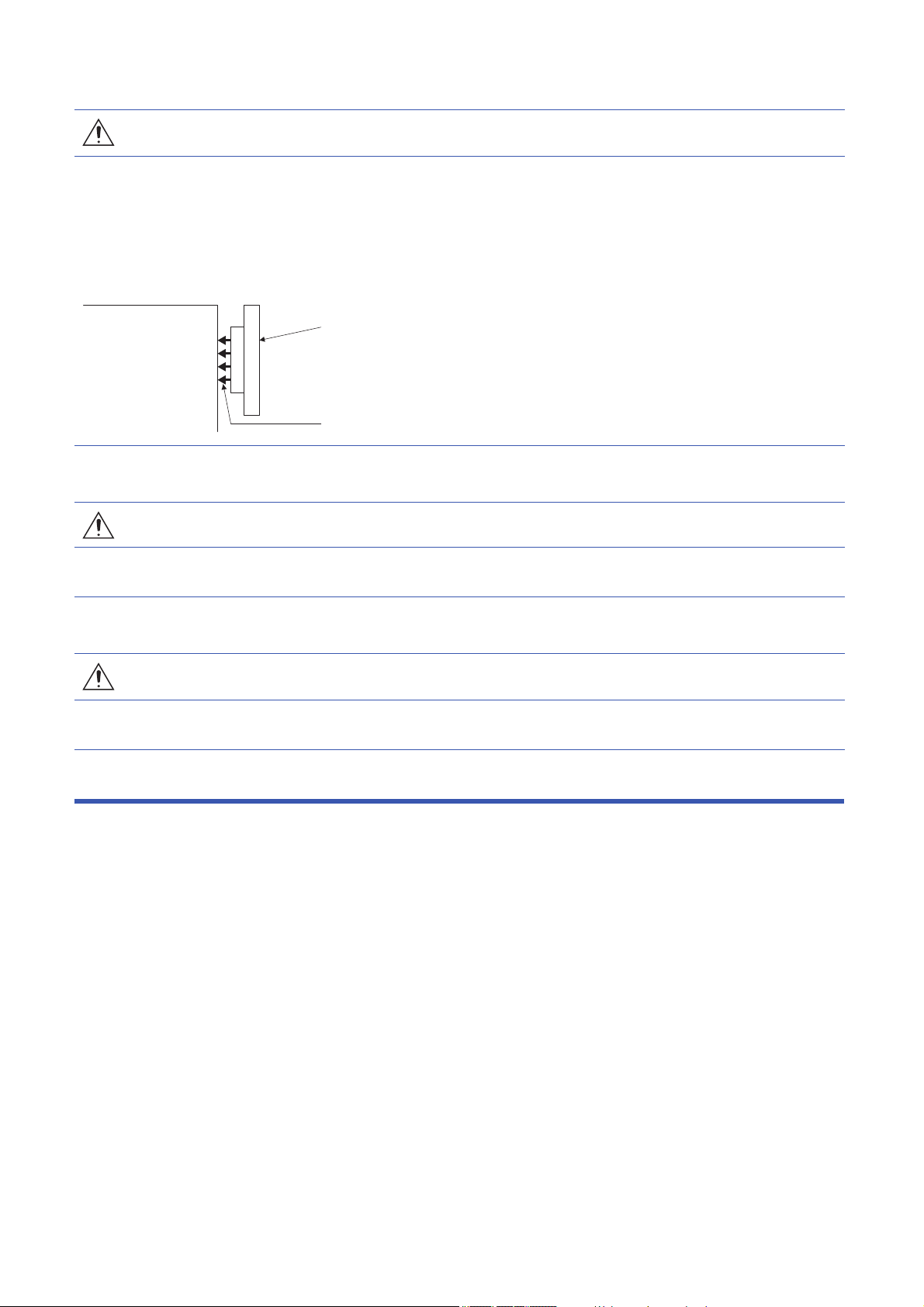
Handling of Linear Servo Motor
Primary side
Laminated core
Molded resin
Molded resin or stainless cover
Motor coil
Permanent magnet
Mounting part (yoke)
Secondary side
Structure of linear servo motor
Linear servo motor has the primary side which consists of the iron core and coil, and the secondary side which consists of the
mounting part (yoke) and permanent magnet. (excluding coreless type LM-U2P_)
■Primary side
The primary side has the motor core with winding and is covered with the molded resin.
■Secondary side
The secondary side has the permanent magnet on the mounting part (yoke) and is covered with the molded resin or stainless
cover.
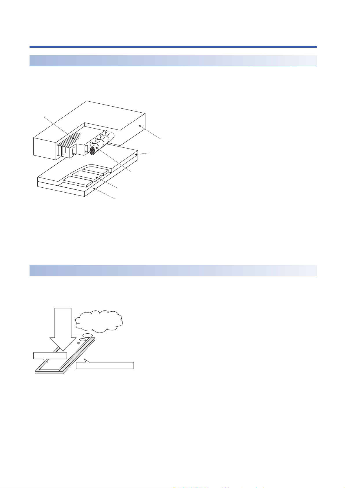
Magnetic attraction force
The secondary side of the linear servo motor contains a strong permanent magnet, so a magnetic attraction force (the force
by which a magnet attracts magnetic bodies) is generated toward magnetic bodies such as iron.
This magnetic attraction force is always acting regardless of linear servo motor power on/off.
Always acting
regardless of on/off
of the power
Magnetic attraction
force
Magnet side face
Mounting part (yoke) side face
3
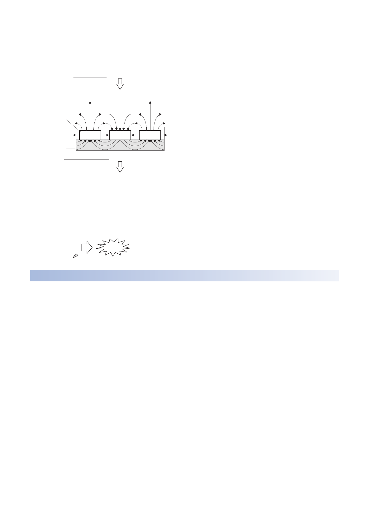
The magnetic fluxes generating from the permanent magnet disperse in the air from the magnet face side (facing the primary
Magnet side face...Dispersion of magnetic fluxes
Generating magnetic attraction force
Magnetic
fluxes
Permanent magnet
North pole South pole North pole
Mounting part side face...No dispersion of magnetic fluxes
Mounting
part (yoke)
Not generating magnetic attraction force
If an A4-size iron sheet is fully attracted
A4
(21 × 29.7 cm)
Approx. 2.5 t
side), and most of them do not leak to the mounting part (yoke) surface side for its structure.
Because of this, a magnetic attraction force occurs on the magnet face side of the secondary side, not on the mounting part
(yoke) surface side.
The permanent magnet used for the linear servo motor is very strong.
When an A4-sized iron sheet is fully attracted, the magnetic attraction force becomes as high as 2.5 t. Use abundance of
caution with the handling.
Magnetic attraction force = 400 [kPa]
For safety
The magnetic attraction force is in inverse proportion to square of the distance to a magnetic body, so it drastically increases
when the distance becomes small.
When mounting the secondary side of linear side motor, ensure the sufficient distance from the magnetic bodies around it and
securely fix those magnetic bodies.
4
Notes on handling
Primary side Secondary side
Discard as industrial waste.
After demagnetizing over 300 °C,
discard as industrial waste.
• Handling must be done by the engineers who have a full knowledge of this product.
• One who uses a medical device like a pacemaker must keep away from the product and equipment.
• Do not wear metals such as watch, pierced earring, necklace, etc.
• Use nonmagnetic tools. (Example) Explosion-proof beryllium copper alloy safety tools: bealon (NGK)
• Do not put magnetic card, watch, portable phone, etc. close to the motor.
• Do not add a shock or a stress on the mold part of the product. (Otherwise, the linear servo motor may be damaged.)
• Put a sign such as "Note a strong magnetic.", and take action by giving cautions to the surrounding, etc.
Disposal of linear servo motor
• The primary side must be discarded as industrial waste.
• The secondary side must be discarded as industrial waste after demagnetization over 300 ˚C.
• When the demagnetization is not possible, pack into a box and return to your local sales office.
• Do not leave the product.
Cables used for wiring
Wires mentioned in this user’s manual are selected based on the ambient temperature of 40 °C.
U.S. CUSTOMARY UNITS
U.S. customary units are not shown in this manual. Convert the values if necessary according to the following table.
Quantity SI (metric) unit U.S. customary unit
Mass 1 [kg] 2.2046 [lb]
Length 1 [mm] 0.03937 [inch]
Torque 1 [N•m] 141.6 [oz•inch]
-4
Moment of inertia 1 [(× 10
Load (thrust load/axial load) 1 [N] 0.2248 [lbf]
Temperature N [°C] × 9/5 + 32 N [°F]
kg•m2)] 5.4675 [oz•inch2]
5

CONTENTS
SAFETY INSTRUCTIONS. . . . . . . . . . . . . . . . . . . . . . . . . . . . . . . . . . . . . . . . . . . . . . . . . . . . . . . . . . . . . . . . . . . .1
DISPOSAL OF WASTE . . . . . . . . . . . . . . . . . . . . . . . . . . . . . . . . . . . . . . . . . . . . . . . . . . . . . . . . . . . . . . . . . . . . . .2
Handling of Linear Servo Motor. . . . . . . . . . . . . . . . . . . . . . . . . . . . . . . . . . . . . . . . . . . . . . . . . . . . . . . . . . . . . . . .3
Cables used for wiring. . . . . . . . . . . . . . . . . . . . . . . . . . . . . . . . . . . . . . . . . . . . . . . . . . . . . . . . . . . . . . . . . . . . . . .5
U.S. CUSTOMARY UNITS . . . . . . . . . . . . . . . . . . . . . . . . . . . . . . . . . . . . . . . . . . . . . . . . . . . . . . . . . . . . . . . . . . .5
CHAPTER 1 Handling of Linear Servo Motor 8
1.1 Design Instructions . . . . . . . . . . . . . . . . . . . . . . . . . . . . . . . . . . . . . . . . . . . . . . . . . . . . . . . . . . . . . . . . . . . . . . . 8
1.2 Instructions on installation operation . . . . . . . . . . . . . . . . . . . . . . . . . . . . . . . . . . . . . . . . . . . . . . . . . . . . . . . 10
1.3 Instructions on storage. . . . . . . . . . . . . . . . . . . . . . . . . . . . . . . . . . . . . . . . . . . . . . . . . . . . . . . . . . . . . . . . . . . 12
Storage method. . . . . . . . . . . . . . . . . . . . . . . . . . . . . . . . . . . . . . . . . . . . . . . . . . . . . . . . . . . . . . . . . . . . . . . . . . 13
1.4 Instructions for disposal. . . . . . . . . . . . . . . . . . . . . . . . . . . . . . . . . . . . . . . . . . . . . . . . . . . . . . . . . . . . . . . . . . 13
CHAPTER 2 INSPECTION 14
2.1 Inspections on primary side (coil) . . . . . . . . . . . . . . . . . . . . . . . . . . . . . . . . . . . . . . . . . . . . . . . . . . . . . . . . . . 14
2.2 Inspections on secondary side (magnet) . . . . . . . . . . . . . . . . . . . . . . . . . . . . . . . . . . . . . . . . . . . . . . . . . . . . 15
2.3 Inspections of linear encoder. . . . . . . . . . . . . . . . . . . . . . . . . . . . . . . . . . . . . . . . . . . . . . . . . . . . . . . . . . . . . . 15
CHAPTER 3 REPLACEMENT OF LINEAR SERVO MOTOR IN THE ABSOLUTE POSI-
TION DETECTION SYSTEM 16
3.1 Replacement of primary side (coil) or secondary side (magnet) . . . . . . . . . . . . . . . . . . . . . . . . . . . . . . . . . 16
3.2 Replacement of linear encoder . . . . . . . . . . . . . . . . . . . . . . . . . . . . . . . . . . . . . . . . . . . . . . . . . . . . . . . . . . . . 16
CHAPTER 4 CONNECTION OF SERVO AMPLIFIER AND LINEAR SERVO MOTOR 18
4.1 Precautions for wiring. . . . . . . . . . . . . . . . . . . . . . . . . . . . . . . . . . . . . . . . . . . . . . . . . . . . . . . . . . . . . . . . . . . . 19
4.2 Power supply cable wiring diagrams . . . . . . . . . . . . . . . . . . . . . . . . . . . . . . . . . . . . . . . . . . . . . . . . . . . . . . . 19
LM-H3/LM-U2/LM-K2 series . . . . . . . . . . . . . . . . . . . . . . . . . . . . . . . . . . . . . . . . . . . . . . . . . . . . . . . . . . . . . . . . 19
LM-F series . . . . . . . . . . . . . . . . . . . . . . . . . . . . . . . . . . . . . . . . . . . . . . . . . . . . . . . . . . . . . . . . . . . . . . . . . . . . . 21
4.3 Selection example of wires. . . . . . . . . . . . . . . . . . . . . . . . . . . . . . . . . . . . . . . . . . . . . . . . . . . . . . . . . . . . . . . . 22
CHAPTER 5 Linear servo motor 23
5.1 Rating plate . . . . . . . . . . . . . . . . . . . . . . . . . . . . . . . . . . . . . . . . . . . . . . . . . . . . . . . . . . . . . . . . . . . . . . . . . . . . 23
5.2 Environment. . . . . . . . . . . . . . . . . . . . . . . . . . . . . . . . . . . . . . . . . . . . . . . . . . . . . . . . . . . . . . . . . . . . . . . . . . . . 25
5.3 LM-H3 series . . . . . . . . . . . . . . . . . . . . . . . . . . . . . . . . . . . . . . . . . . . . . . . . . . . . . . . . . . . . . . . . . . . . . . . . . . . 26
Model designation . . . . . . . . . . . . . . . . . . . . . . . . . . . . . . . . . . . . . . . . . . . . . . . . . . . . . . . . . . . . . . . . . . . . . . . . 26
Combinations of servo amplifiers and linear servo motors . . . . . . . . . . . . . . . . . . . . . . . . . . . . . . . . . . . . . . . . . 27
LM-H3 series specification list . . . . . . . . . . . . . . . . . . . . . . . . . . . . . . . . . . . . . . . . . . . . . . . . . . . . . . . . . . . . . . . 28
Thrust characteristics . . . . . . . . . . . . . . . . . . . . . . . . . . . . . . . . . . . . . . . . . . . . . . . . . . . . . . . . . . . . . . . . . . . . . 29
Installation . . . . . . . . . . . . . . . . . . . . . . . . . . . . . . . . . . . . . . . . . . . . . . . . . . . . . . . . . . . . . . . . . . . . . . . . . . . . . . 31
LM-H3 series primary side (coil) dimensions. . . . . . . . . . . . . . . . . . . . . . . . . . . . . . . . . . . . . . . . . . . . . . . . . . . . 34
LM-H3 series secondary side (magnet) dimensions . . . . . . . . . . . . . . . . . . . . . . . . . . . . . . . . . . . . . . . . . . . . . . 35
5.4 LM-U2 series . . . . . . . . . . . . . . . . . . . . . . . . . . . . . . . . . . . . . . . . . . . . . . . . . . . . . . . . . . . . . . . . . . . . . . . . . . . 37
Model designation . . . . . . . . . . . . . . . . . . . . . . . . . . . . . . . . . . . . . . . . . . . . . . . . . . . . . . . . . . . . . . . . . . . . . . . . 37
Combinations of servo amplifiers and linear servo motors . . . . . . . . . . . . . . . . . . . . . . . . . . . . . . . . . . . . . . . . . 39
LM-U2 series specification list . . . . . . . . . . . . . . . . . . . . . . . . . . . . . . . . . . . . . . . . . . . . . . . . . . . . . . . . . . . . . . . 40
Thrust characteristics . . . . . . . . . . . . . . . . . . . . . . . . . . . . . . . . . . . . . . . . . . . . . . . . . . . . . . . . . . . . . . . . . . . . . 42
Installation . . . . . . . . . . . . . . . . . . . . . . . . . . . . . . . . . . . . . . . . . . . . . . . . . . . . . . . . . . . . . . . . . . . . . . . . . . . . . . 43
6

LM-U2 series primary side (coil) dimensions. . . . . . . . . . . . . . . . . . . . . . . . . . . . . . . . . . . . . . . . . . . . . . . . . . . . 46
LM-U2 series secondary side (magnet) dimensions . . . . . . . . . . . . . . . . . . . . . . . . . . . . . . . . . . . . . . . . . . . . . . 49
5.5 LM-F series. . . . . . . . . . . . . . . . . . . . . . . . . . . . . . . . . . . . . . . . . . . . . . . . . . . . . . . . . . . . . . . . . . . . . . . . . . . . . 51
Model designation . . . . . . . . . . . . . . . . . . . . . . . . . . . . . . . . . . . . . . . . . . . . . . . . . . . . . . . . . . . . . . . . . . . . . . . . 51
Combinations of servo amplifiers and linear servo motors . . . . . . . . . . . . . . . . . . . . . . . . . . . . . . . . . . . . . . . . . 52
LM-F series specification list . . . . . . . . . . . . . . . . . . . . . . . . . . . . . . . . . . . . . . . . . . . . . . . . . . . . . . . . . . . . . . . . 52
Thrust characteristics . . . . . . . . . . . . . . . . . . . . . . . . . . . . . . . . . . . . . . . . . . . . . . . . . . . . . . . . . . . . . . . . . . . . . 53
Installation . . . . . . . . . . . . . . . . . . . . . . . . . . . . . . . . . . . . . . . . . . . . . . . . . . . . . . . . . . . . . . . . . . . . . . . . . . . . . . 54
Liquid cooling. . . . . . . . . . . . . . . . . . . . . . . . . . . . . . . . . . . . . . . . . . . . . . . . . . . . . . . . . . . . . . . . . . . . . . . . . . . . 57
LM-F series primary side (coil) dimensions . . . . . . . . . . . . . . . . . . . . . . . . . . . . . . . . . . . . . . . . . . . . . . . . . . . . . 58
LM-F series secondary side (magnet) dimensions . . . . . . . . . . . . . . . . . . . . . . . . . . . . . . . . . . . . . . . . . . . . . . . 59
5.6 LM-K2 series . . . . . . . . . . . . . . . . . . . . . . . . . . . . . . . . . . . . . . . . . . . . . . . . . . . . . . . . . . . . . . . . . . . . . . . . . . . 60
Model designation . . . . . . . . . . . . . . . . . . . . . . . . . . . . . . . . . . . . . . . . . . . . . . . . . . . . . . . . . . . . . . . . . . . . . . . . 60
Combinations of servo amplifiers and linear servo motors . . . . . . . . . . . . . . . . . . . . . . . . . . . . . . . . . . . . . . . . . 61
LM-K2 series specification list . . . . . . . . . . . . . . . . . . . . . . . . . . . . . . . . . . . . . . . . . . . . . . . . . . . . . . . . . . . . . . . 62
Thrust characteristics . . . . . . . . . . . . . . . . . . . . . . . . . . . . . . . . . . . . . . . . . . . . . . . . . . . . . . . . . . . . . . . . . . . . . 63
Installation . . . . . . . . . . . . . . . . . . . . . . . . . . . . . . . . . . . . . . . . . . . . . . . . . . . . . . . . . . . . . . . . . . . . . . . . . . . . . . 64
LM-K2 series primary side (coil) dimensions. . . . . . . . . . . . . . . . . . . . . . . . . . . . . . . . . . . . . . . . . . . . . . . . . . . . 69
LM-K2 series secondary side (magnet) dimensions . . . . . . . . . . . . . . . . . . . . . . . . . . . . . . . . . . . . . . . . . . . . . . 71
REVISIONS. . . . . . . . . . . . . . . . . . . . . . . . . . . . . . . . . . . . . . . . . . . . . . . . . . . . . . . . . . . . . . . . . . . . . . . . . . . . . .74
WARRANTY . . . . . . . . . . . . . . . . . . . . . . . . . . . . . . . . . . . . . . . . . . . . . . . . . . . . . . . . . . . . . . . . . . . . . . . . . . . . .75
TRADEMARKS . . . . . . . . . . . . . . . . . . . . . . . . . . . . . . . . . . . . . . . . . . . . . . . . . . . . . . . . . . . . . . . . . . . . . . . . . . .76
CONTENTS
7

1 Handling of Linear Servo Motor
Precautions
• MR-J5-_G_-RJ and MR-J5-_A_-RJ will be available in the future.
The linear servo motor uses a strong magnet on the secondary side. Incorrect handling is extremely dangerous and may
cause serious accidents. Please read this chapter and thoroughly understand the contents beforehand, and handle carefully.
1.1 Design Instructions
• Although dynamic brake can be applied by the servo amplifier, the coasting distance becomes longer when the mass of the
moving part is heavy or when the speed is high. This is highly dangerous and may result in collision into the stroke end.
Install anti-collision mechanism such as an air brake, or an electrical and mechanical stopper such as shock absorber to
reduce the impact of the movable part. (No linear servo motor with an electromagnetic brake is available.)
• The magnetic attraction force operating between the primary and secondary sides is always in operation even when the
linear servo motor power is not turned on. As such, the machine must be designed with sufficient rigidity to support the
magnetic attraction force and maintain the accuracy.
• Since the running load by friction increases in proportion to the magnetic attraction force, arrange to reduce friction as
much as possible, such as installing the linear guide with high accuracy.
• When the linear servo motor is used on a vertical axis, a drop prevention system such as a spring and counter balance is
required on the machine side.
• Install the linear servo motor in such a way for the thrust to operates on the center of gravity of the moving part. When the
thrust does not operates on the center of gravity of the moving part, the moment occurs.
• If magnetic chips such as iron fragments or the like is present, it may stick to the permanent magnet on the secondary side
and cause malfunction. In such environment, take measures to prevent adsorption and penetration of magnetic chips.
• Oil proof and dust proof measures for the linear encoder is required, more so than for the linear servo motor. Contact each
linear encoder manufacturer for details.
• Do not hit the primary side against the stopper. The primary side may be damaged. Arrange for the table attached to the
primary side to hit the stopper.
• Do not use the screw holes of the linear servo motor for any purposes, other than for machine installation.
• For installation, use all the screw holes provided in the linear servo motor.
• When a dangerous condition is presumed at the time of stoppage and product failure, prevent it by providing an external
braking system for maintenance use.
• Provide an adequate protection to prevent unexpected restart after an instantaneous power failure.
• Arrange for the primary and secondary side to satisfy the mounting dimensions.
• When using linear guide as base, check the specifications, and determine the processing accuracy. Contact each linear
guide manufacturer for details.
• Movable range of the linear servo motor should be equal to or less than the effective measurement length of the linear
encoder.
• For the stopper, use shock-absorbing material such as polyurethane rubber.
• In the condition where cutting fluid or lubricating oil are c
humidity, continuous operation of the linear servo motor for a long period of time may results in the deterioration on the
insulation of the linear servo motor. Provide measures such as oil proof, dust proof cover, and dew condensation prevention
to protect the linear servo motor.
• Arrange in consideration the installation work. For details of the installation, refer to the following and the "Installation"
section of each linear servo motor series.
Page 10 Instructions on installation operation
• For high-accuracy positioning, ensure that the machine to be as rigid as possible, and increase the mechanical resonance
point.
• To ensure the utmost rigidity of the machines, adopt an integrated structure to the base. When using bolts, etc. as fastener
is inevitable, use thick bolt with shorter neck size. Make the pitch dimension of bolt holes as small as possible.
onstantly applied, and condensation occurs due to excessive
8
1 Handling of Linear Servo Motor
1.1 Design Instructions
• Make the moving parts as light as possible, and make the base parts heavier and sturdier.
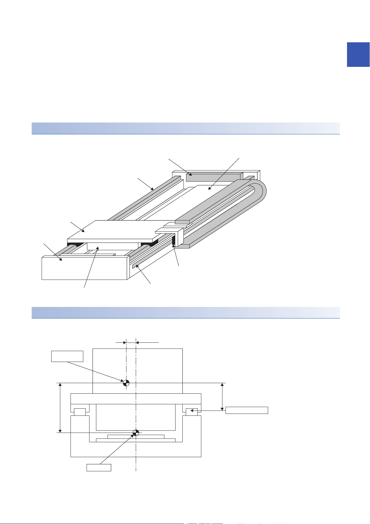
Linear servo motor secondary side
Stopper
Linear guide
Table
Base
Linear encoder head
Linear encoder scale
Linear servo motor primary side
As short as possible
Gravity center
of moving part
As short as possible
As short as
possible
Linear guide center
Thrust center
• When loading works or others on the table, make the center of gravity to be as low as possible. Additionally, position of the
center of gravity should be between the two linear guides.
• Since the movement and accuracy of the machine may be adversely affected, arrange for the center of thrust of the linear
servo motor, and the center of gravity of the moving object, to be closer with one another.
• When the mounting rigidity of the linear encoder is not enough, the feedback signal may be disturbed by the machine
vibration, and the desired performance may not be satisfied. Furthermore, as the same condition also applies when the
linear encoder is susceptible to electric noise, arrange and install in such a way that would be unaffected by vibration and
electric noise.
• Establish a structure that can withstand high speed and high acceleration/deceleration.
Basic structure of linear servo motor incorporated slider
The following diagram shows an example of the basic structure of linear slider.
1
Instructions on the structure of linear slider
Instructions on the structure of linear slider are shown on the following diagram.
1 Handling of Linear Servo Motor
1.1 Design Instructions
9
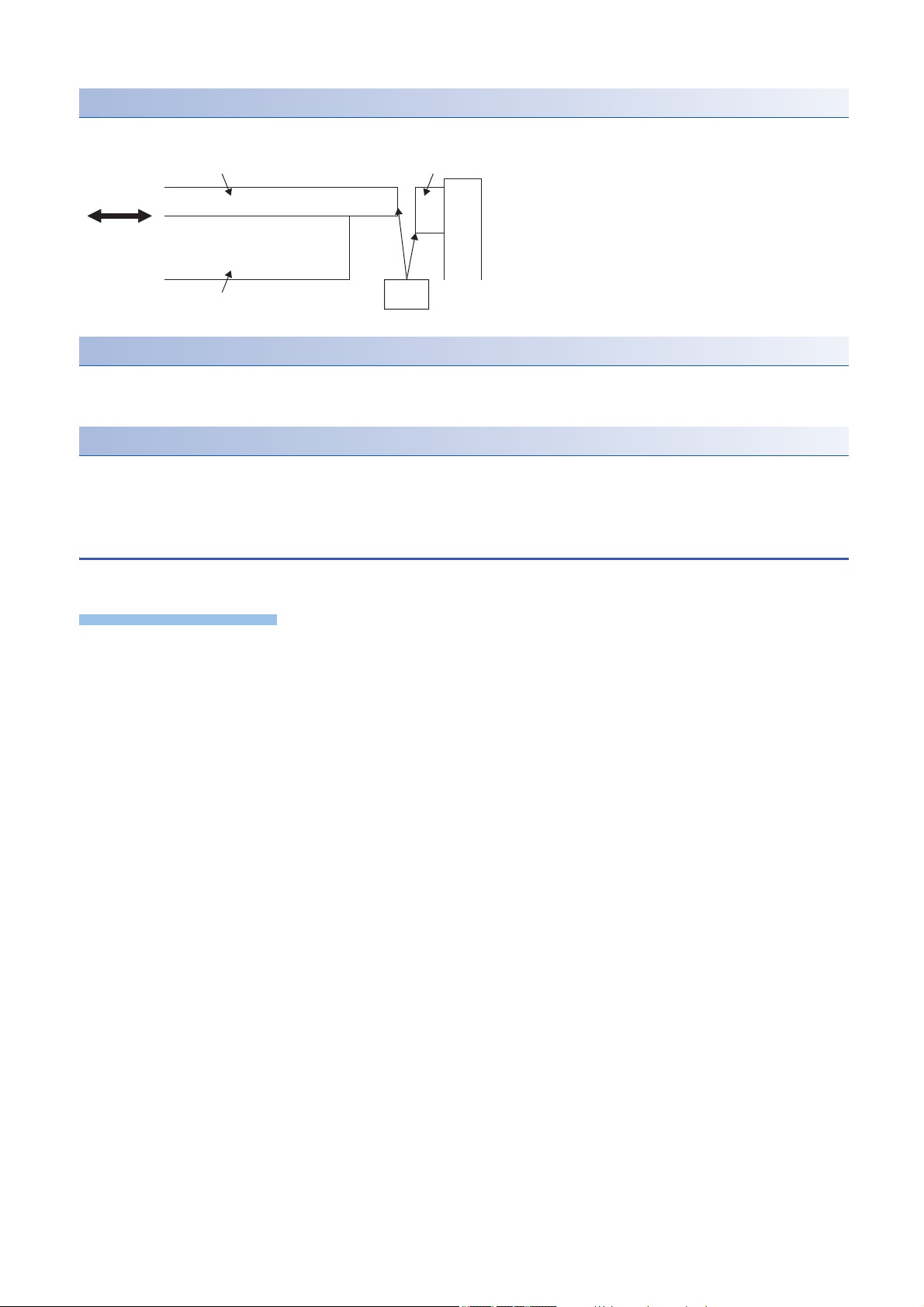
Stopper
Precautions
Stopper
Table
Contact
surface
Primary side
As shown in the following figure, arrange for the table attached to the primary side to hit the stopper.
LINEAR ENCODER
Oil proof and dust proof measures for the linear encoder is required, more so than for the linear servo motor.
Contact each linear encoder manufacturer for details.
Linear guide
Install the linear guide with high accuracy.
Contact each linear guide manufacturer for details.
1.2 Instructions on installation operation
Instructions on using lifting machines such as crane when installing the linear servo motor are shown below.
• The cables should not be damaged, stressed, loaded, or pinched.
• Install the linear servo motor on incombustible material. Installing them directly or close to combustibles will lead to smoke
or a fire.
• Prevent contaminants such as conductive foreign objects such as screws and metal pieces, and combustible foreign object
such as oil, from entering the linear servo motor.
• Linear servo motor may be hot depending on the operating method. Take safety measures such as providing covers.
• Workers installing linear servo motors and machine operators are not allowed to wear or carry electronic devices (such as
watches, calculators, personal computers), and magnetic recording media (IC cards, magnetic cards, floppy disks, and
others), closer to the secondary side. The magnetic effect may cause operation failure or malfunction.
• Securely fix the linear servo motor to the machine. If attached insecurely, the motor may come off during operation.
• Do not overtighten the eyebolts of the linear servo motor. Tightening too hard may damage the tap.
• Stacking in excess of the specified number of product packages is not allowed.
• Do not hold the cables or connectors when carrying the linear servo motor. Otherwise, it may drop.
• Install the linear servo motor in a place that can withstand the mass, in accordance with the user’s manual.
• When installing on the secondary side, use non-magnetic tools.
• Securely fix the linear servo motor to the machine. If attached insecurely, the motor may come off during operation.
• The moving direction of the linear servo motor and linear encoder must match. Otherwise, the linear servo motor may
operate unexpectedly.
• To prevent a connection failure, malfunction, or others, do not strike the connector.
• Use the product within the specified environment. For the environment conditions, refer to the specifications of the linear
servo motor series.
• To prevent rust, do not touch the linear servo motor with bare hands.
• The primary side and secondary side may be damaged by a fall or shock.
• Do not install and operate the servo amplifier and the linear servo motor which have been damaged, or with any parts
• The permanent magnet on the secondary side of the linear servo motor has a suction force against magnetic parts.
missing.
Therefore, people who are using medical device such as a pacemaker must check with the medical device manufacturer
10
1 Handling of Linear Servo Motor
1.2 Instructions on installation operation
whether they can work in such environment.
• On the packing condition (cardboard) shipped from our company, although the magnet on the secondary side does not
have any serious impact on the outside, do not place the magnetic parts (including the primary side, other secondary side,
and tools) close to the secondary side until the linear servo motor is assembled to the machine. Be cautious in the
workplace and its surroundings.
• For installation of the linear servo motor and working near the linear servo motor, use non-magnetic tools. They are
necessary to ensure safety and improve workability. Especially when installing the primary side after the installation of the
secondary side. For screws to be used, refer to the dimensions of each linear servo motor series.
• Do not get on or put heavy load on the equipment.
• Do not drop or strike the linear servo motor.
• To prevent a fire or injury from occurring in case of an earthquake or other natural disasters, securely install, mount, and
wire the linear servo motor in accordance with the user’s manual.
• To prevent an electric shock or a fire, do not disassemble, repair, or modify the product. Disassembled, repaired, and/or
modified products are not covered under warranty.
• Keep the cumulative pitch error of the mounting screw holes to within ±0.2 mm (0.1 mm for LM-K2 series). When two or
more secondary sides are installed, clearance may be left between the secondary sides depending on the installing method
and the number of secondary sides.
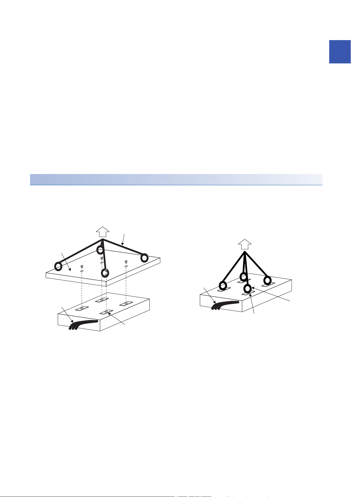
Primary side (coil)
For lifting the primary side, lift the tool for lifting attached to the primary side or lift the eyebolt attached to the screw hole for
primary-side mounting as shown in the following diagram.
When lifting, do not add any stress on the mold part and the power supply cable by the wire, and the like.
Set the lifting points on both longitudinal ends (two or more).
1
Tool for lifting
Power cable or others
Wire or others
Wire or others
Power cable or others
Eyebolt
Screw hole for primary-side mounting
Screw hole for primary-side mounting
When using the tool for lifting When using the eyebolts
1 Handling of Linear Servo Motor
1.2 Instructions on installation operation
11
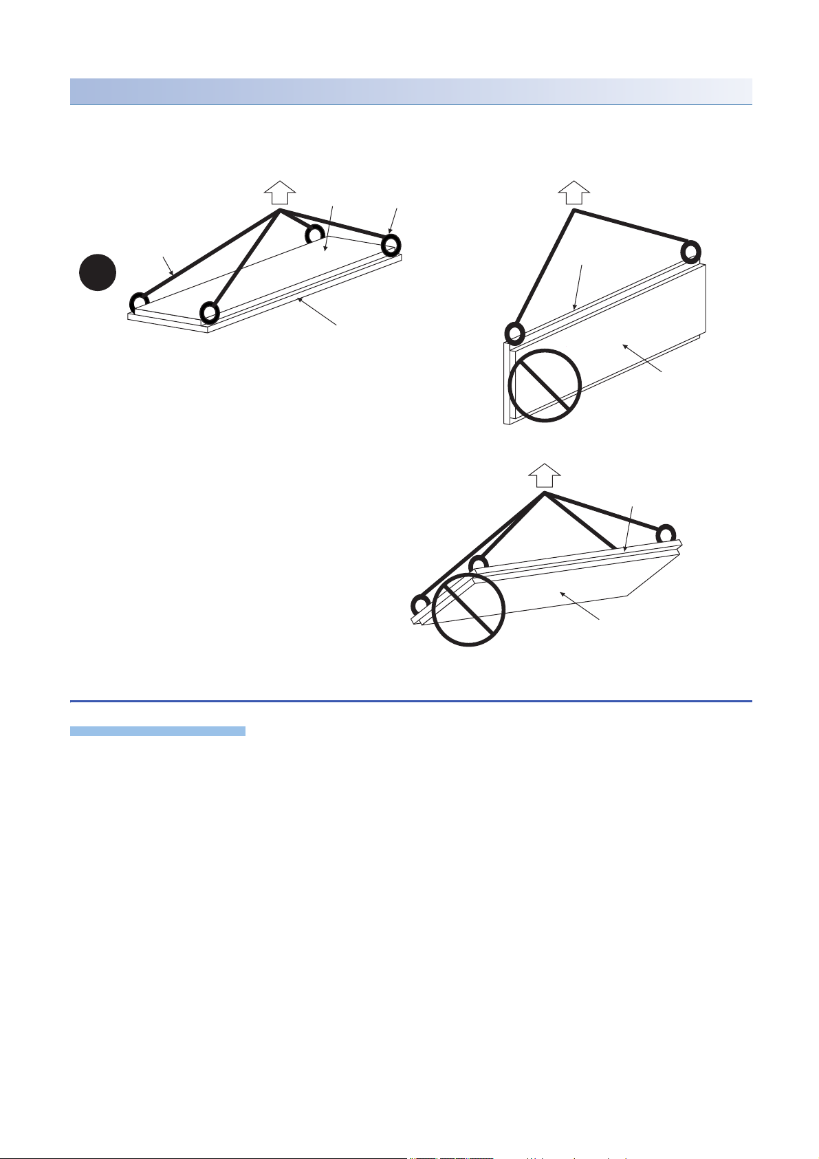
Secondary side (magnet)
Precautions
Magnet side face
Eyebolt
Wire or others
Mounting part (yoke)
side face
Mounting part (yoke) side face
Magnet side face
Mounting part (yoke) side face
Magnet side face
As shown in the following diagram, for lifting the secondary side, attach eyebolts to the secondary side mounting screw hole.
When lifting the secondary side, to avoid the danger due to the magnetic attraction force, make the magnet face side upward,
and set the lifting points in four or more points.
1.3 Instructions on storage
Note the following when storing the linear servo motor for an extended period of time (guideline: three months or longer).
• Always store the linear servo motor indoors, in a clean and dry place.
• When storing in a dusty and humid area, take measures such as covering the whole product.
• Although the linear servo motor has been rust-proofed with paint and rust prevention oil before shipment, rust may appear
if the linear servo motor is stored in bad conditions for an extended period of time. When storing the linear servo motor for
longer than six months, apply rust prevention oil again to the machine processing surfaces such as the rotor rotating part.
• When the product has been stored for an extended period of time, contact your local sales office.
• Be sure to follow the storage conditions (ambient temperature and humidity, etc.).
• Store the product in the environment with no exposure to rain water, dust, oil, and chemical materials adhesion.
• Do not shock the servo amplifier or linear servo motor.
12
1 Handling of Linear Servo Motor
1.3 Instructions on storage
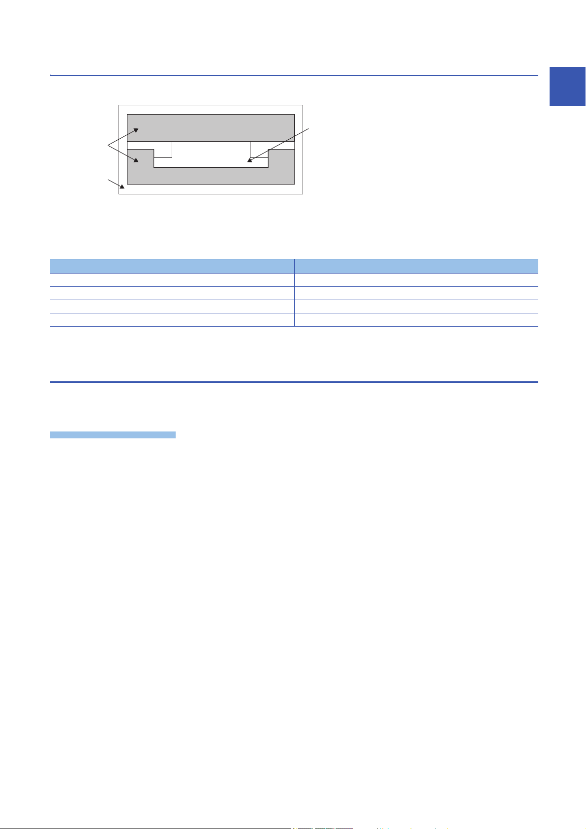
Storage method
Precautions
Product
Shock-absorbing
material
Package
• Correctly store the linear servo motor in the package.
• When storing the secondary side, put a display such as "Handle with care - Strong magnetic field" on the package or
storage shelf, and also take measures in drawing attention to the surrounding.
• Do not use the deformed packaging box.
• Store the equipment under the following environment.
Item Environment
Ambient temperature -15 ˚C to 70 ˚C (non-freezing)
Ambient humidity 10 %RH to 90 %RH (non-condensing)
Ambience Indoors (no direct sunlight); no corrosive gas, inflammable gas, oil mist or dust
Vibration resistance 49 m/s
• When lifting the product using a suspender, do not apply shock and stress on the mold part.
2
1.4 Instructions for disposal
1
Demagnetize the secondary side by heating over 300 ˚C, and dispose the linear servo motor in accordance with the Law for
Promotion of Effective Utilization of Resources.
• The servo amplifier and the primary side of the linear servo motor must be disposed in accordance with "DISPOSAL OF
WASTE".
• Since the secondary side of the linear servo motor uses the permanent magnet, demagnetize the entire secondary side by
heating over 300 ˚C, then dispose in accordance with "DISPOSAL OF WASTE".
• The permanent magnet on the secondary side of the linear servo motor has a suction force against magnetic parts.
Therefore, people who are using medical device such as a pacemaker must check with the medical device manufacturer
whether they can work in such environment.
• Use caution during and after disassembly, prior to demagnetizing the magnetic force on the secondary side.
• When disassembling and disposing the linear servo motor, do not place the magnetic parts (including the primary side,
other secondary side, and tools) closer to the secondary side.
• Use non-magnetic tools to disassemble and dispose the linear servo motor, or when working near the motor. They are
necessary to ensure safety and improve workability.
1 Handling of Linear Servo Motor
1.4 Instructions for disposal
13

2 INSPECTION
Precautions
The linear servo motor functions as motor when mounted in the equipment (built-in). The IP rating is IP00. Perform the
following inspections and cleaning.
• The linear servo motor is structurally unrepairable. If the linear servo motor is damaged, it must be replaced.
• Do not disassemble and/or repair the equipment on customer side.
• Discoloration of the molded resin of the linear servo motor may occurs. Though the lost color may not be the cause of
malfunction, inspect the molded resin.
• If the magnet protective cover is stainless, it may be deformed or damaged if it is strongly pressed or a magnetic body is
attached to it. Take special care of the end part of the product, as it is easily deformed.
2.1 Inspections on primary side (coil)
Attachment of water and oil
Check that the primary and secondary side of the linear servo motor are not wet with water or oil. When the linear servo motor
is wet, the insulation on the primary side deteriorates, and may cause a malfunction. Establish the mechanical structure in
which water and oil are not attached to the linear servo motor.
Molded resin
Check the molded resin on the primary side for fragmentations, breakages, and cracks. If fragmentations, breakages, and
cracks are found, replace the primary side, as insulation have deteriorated and may cause a malfunction.
Scratches on the surface that faces the secondary side (magnet)
Check for scratches on the primary-side surface which faces the secondary side. If there are scratches on the primary-side
surface which faces the secondary side, replace the primary side. If scratches appear on the primary side due to a foreign
matter caught in the empty clearance between the primary and secondary side, remove the foreign matter, and establish a
mechanical structure to prevent similar situation.
Looseness of mounting screws
Check for loose mounting screws on the primary side. When the mounting screws on the primary side are loose, tighten the
applicable screws.
Scratches and cracks on the linear servo motor cables
Check for scratches and cracks on the linear servo motor cables. If the linear servo motor cables have any scratches or
cracks, replace the applicable cables. Especially when the cables are moved, make inspections periodically.
14
2 INSPECTION
2.1 Inspections on primary side (coil)

2.2 Inspections on secondary side (magnet)
Attachment of water and oil
Check that the primary and secondary side of the linear servo motor are not wet with water or oil. When the linear servo motor
is wet, the insulation on the primary side deteriorates, and may cause a malfunction. Establish the mechanical structure in
which water and oil are not attached to the linear servo motor.
Exposure and levitation of magnet
Check for the exposure and levitation of the magnet on the secondary side. If the magnet on the secondary side is exposed or
levitated, replace the secondary side immediately.
Magnet protective cover
The secondary side surface is covered with the mold resin or stainless cover to protect the magnet.
• When a foreign matter such as dust is attached to the surface, wipe gently with acetone soaked cloth.
• Check the molded resin on the secondary side for fragmentations, breakages, and cracks. If fragmentations, breakages,
and cracks are found, replace the secondary side.
• Check for scratches on the molded resin of the secondary side. When the magnet is exposed by the scratches on the
molded resin of the secondary side, replace the secondary side. If scratches appear on the secondary side due to a foreign
matter caught in the empty clearance between the primary and secondary side, remove the foreign matter, and establish a
mechanical structure to prevent similar situation.
2
Looseness of mounting screws
Check for loose mounting screws on the secondary side. When the mounting screws on the secondary side are loose, tighten
the applicable screws.
2.3 Inspections of linear encoder
The inspections of the linear encoder may be required. For the inspections of the linear encoder, contact the linear encoder
manufacturer.
2 INSPECTION
2.2 Inspections on secondary side (magnet)
15
3 REPLACEMENT OF LINEAR SERVO MOTOR IN
1)
THE ABSOLUTE POSITION DETECTION
SYSTEM
3.1 Replacement of primary side (coil) or secondary
side (magnet)
After replacing the primary side or the secondary side, carry out the magnetic pole detection again.
3.2 Replacement of linear encoder
After replacing the linear encoder, carry out the magnetic pole detection and homing.
Checking method of the mounting position of linear encoder
1. Before replacing the linear encoder, check the encoder information using MR Configurator2, with the linear servo motor
fixed at the specified position.
2. Replace the linear encoder with a position gap before and after the replacement at ± 0.1 mm.
3. After replacing the linear encoder, check the encoder information using MR Configurator2, with the linear servo motor
fixed at the specified position again.
4. Confirm that the value converted from the difference of the encoder information (resolution unit), before and after
replacement of the linear encoder, is ± 0.1 mm or less.
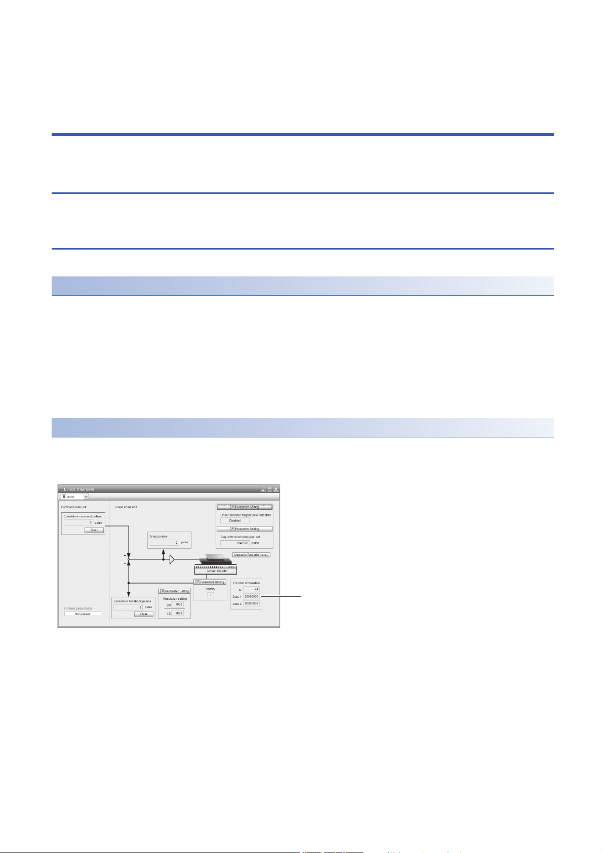
Reading method of encoder information by using MR Configurator2
1. Check that the personal computer is connected with the servo amplifier, and select "Diagnosis" and then select "Linear
diagnosis". The following window appears.
2. Reading the encoder information data 1)
16
3 REPLACEMENT OF LINEAR SERVO MOTOR IN THE ABSOLUTE POSITION DETECTION SYSTEM
3.1 Replacement of primary side (coil) or secondary side (magnet)

MEMO
3
3 REPLACEMENT OF LINEAR SERVO MOTOR IN THE ABSOLUTE POSITION DETECTION SYSTEM
3.2 Replacement of linear encoder
17
4 CONNECTION OF SERVO AMPLIFIER AND
Precautions
U
M
V
W
U
V
W
U
M
V
W
U
V
W
Linear servo motor Linear servo motorServo amplifier Servo amplifier
LINEAR SERVO MOTOR
• Insulate the conductive parts of the terminals.
• The performance is not guaranteed if the specified servo amplifier and linear servo motor are not combined. If used with
unspecified combination, the servo amplifier or linear servo motor may be damaged or may operate unexpectedly.
• The equipment must be installed in the specified direction.
• Do not install or operate the linear servo motor which has been damaged or has any parts missing.
• Do not modify the linear servo motor.
• To prevent unexpected operation of the linear servo motor, wire the equipment correctly and securely.
• Make sure to connect the cables and connectors by using the fixing screws and the locking mechanism. Otherwise, the
cables and connectors may be disconnected during operation.
• Do not install a power capacitor, surge killer, or radio noise filter (optional FR-BIF(-H)) on the servo amplifier output side.
• To avoid a malfunction, connect the wires to the correct phase terminals (U/V/W) of the servo amplifier and the linear servo
motor.
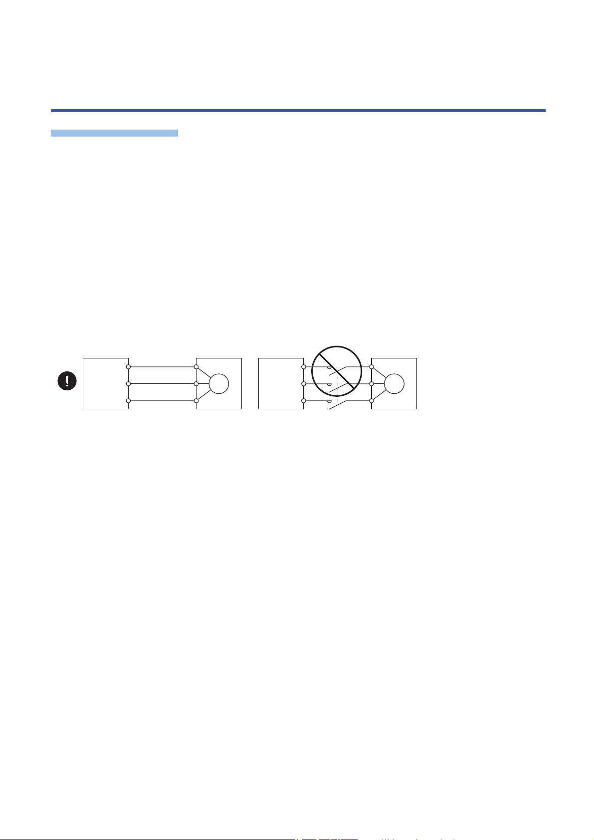
• To prevent abnormal operation and malfunction, connect the servo amplifier power output (U/V/W) to the linear servo motor
power input (U/V/W) directly. Do not connect a magnetic contactor and others between them.
• To prevent a malfunction, do not connect AC power supply directly to the linear servo motor.
• When the wires are not tightened enough to the terminal block, the wires or terminal block may generate heat because of
the poor contact. Be sure to tighten the wires with specified torque.
• The cables such as the power cable deriving from the primary side cannot stand the long-term bending action. Avoid the
bending action by fixing the cables to the moving part or others. Also, use the cable that can withstand the long-term
bending action for the wiring to the servo amplifier.
• Use the linear servo motor with the specified servo amplifier.
• To prevent malfunction, eliminate static electricity before wiring, switch operation, or others.
• To prevent failure and malfunction, only the power/signal specified in the user’s manual should be connected to each
terminal.
• We recommend using HIV wires to connect the servo amplifier to the linear servo motor. Therefore, the recommended wire
sizes may be different from those of the used wires for the previous linear servo motors.
18
4 CONNECTION OF SERVO AMPLIFIER AND LINEAR SERVO MOTOR
4.1 Precautions for wiring
Precautions
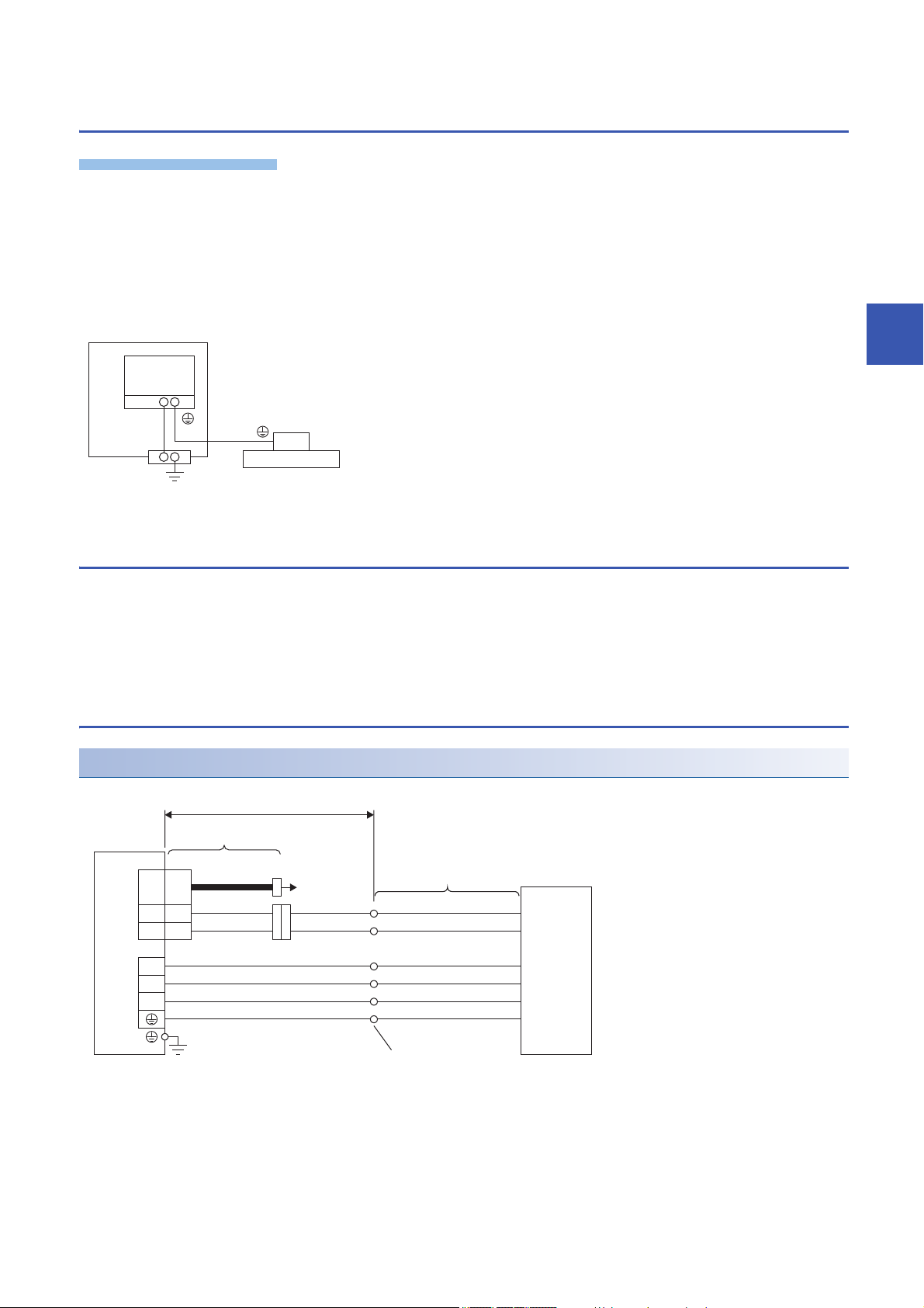
*1
Cabinet
Servo
amplifier
Linear servo motor
Protective
earth (PE)
terminal
*2
THM
SCALE
CN2
CN2
THM1
THM2
5
6
U
V
W
MR-J4THCBL03M
30 m or less
Branch cable
*4
Servo amplifier
Lead wire (Linear servo
motor accessory)
*1
Linear servo motor
To linear
encoder
G1 (black) *3
G2 (black) *3
U (black)
Primary side
V (black)
W (black)
E (green/yellow)
Round crimp terminal
• To avoid a malfunction, connect the wires to the correct phase terminals (U/V/W) of the servo amplifier and the linear servo
motor.
• To prevent a malfunction, do not connect AC power supply directly to the linear servo motor.
For grounding, connect the grounding lead wire from the servo motor to the protective earth (PE) terminal of the servo
amplifier, and then connect the wire from the servo amplifier to the ground via the protective earth of the cabinet. Do not
connect the wire directly to the protective earth (PE) terminal of the cabinet.
*1 The number of protective earth (PE) terminals of the servo amplifier differs depending on the type of servo amplifier.
4.2 Power supply cable wiring diagrams
4
To wire to the servo amplifier, use connectors packed with the servo amplifier or optional connectors.
For connectors, refer to "Wiring CNP1, CNP2, and CNP3" in the following manual.
MR-J5 User's Manual (Hardware)
Refer to the following for the wires used for wiring.
Page 22 Selection example of wires
LM-H3/LM-U2/LM-K2 series
Connection with MR-J5-_ servo amplifier
*1 The signal names (U/V/W/E/G1/G2) are attached on lead wires.
*2 There is no polarity for the thermistor (G1/G2).
*3 The color is blue for LM-H3 series.
*4 When the branch cable is not used, refer to the following manual.
MR-J5 Partner's Encoder User's Manual
4 CONNECTION OF SERVO AMPLIFIER AND LINEAR SERVO MOTOR
4.1 Precautions for wiring
19
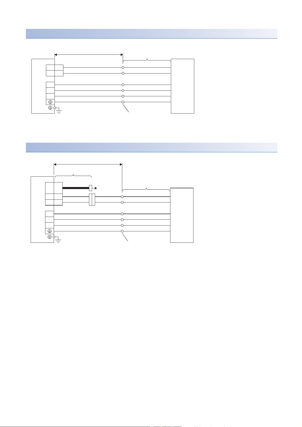
Connection with MR-J5-_-RJ servo amplifier
5
6
THM1
THM2
U
V
W
CN2
*2
Lead wire (Linear servo
motor accessory)
*1
30 m or less
Linear servo motor
Servo amplifier
G1 (black)
*3
G2 (black)
*3
U (black)
Primary side
V (black)
W (black)
E (green/yellow)
Round crimp terminal
THM
SCALE
CN2
5
6
U
V
W
THM1
THM2
CN2A/CN2B/CN2C
CNP3A/CNP3B/CNP3C
*2
MR-J4THCBL03M
30 m or less
Branch cable
*4
Servo amplifier
Lead wire (Linear servo
motor accessory)
*1
Linear servo motor
To linear
encoder
G1 (black)
*3
G2 (black)
*3
U (black)
Primary side
V (black)
W (black)
E (green/yellow)
Round crimp terminal
*1 The signal names (U/V/W/E/G1/G2) are attached on lead wires.
*2 There is no polarity for the thermistor (G1/G2).
*3 The color is blue for LM-H3 series.
Connection with MR-J5W_ servo amplifier
20
*1 The signal names (U/V/W/E/G1/G2) are attached on lead wires.
*2 There is no polarity for the thermistor (G1/G2).
*3 The color is blue for LM-H3 series.
*4 When the branch cable is not used, refer to the following manual.
MR-J5 Partner's Encoder User's Manual
4 CONNECTION OF SERVO AMPLIFIER AND LINEAR SERVO MOTOR
4.2 Power supply cable wiring diagrams
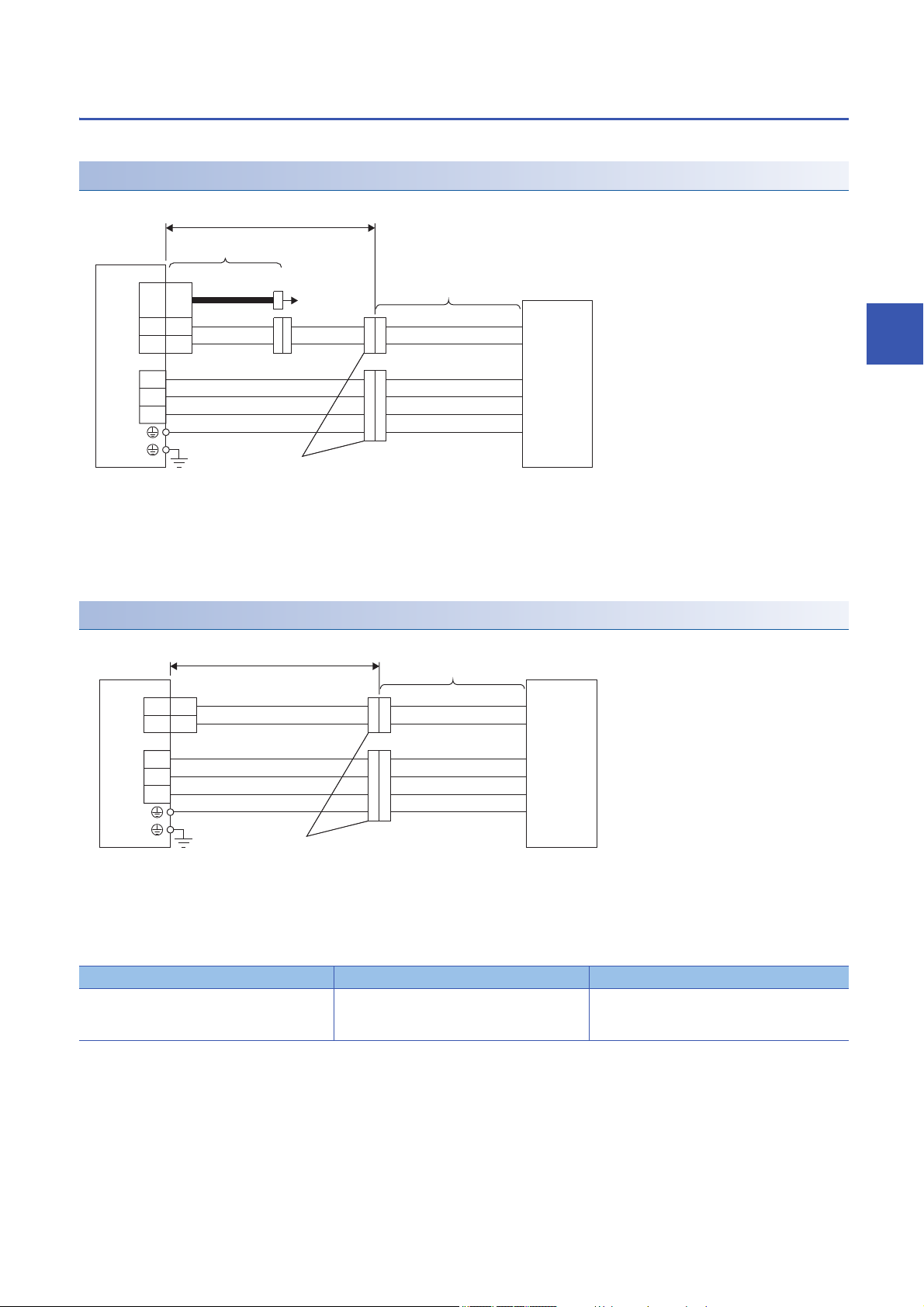
LM-F series
*1
THM
SCALE
CN2
5
6
U
V
W
CN2
U
V
W
E
G1
G2
THM1
THM2
MR-J4THCBL03M
30 m or less
Branch cable
*2
Servo amplifier
Cable (Linear servo
motor accessory)
Linear servo motor
To linear
encoder
Primary side
Junction connector
*3
5
6
U
V
W
CN2
U
V
W
E
G1
G2
*1
THM1
THM2
30 m or less
Cable (Linear servo
motor accessory)
Linear servo motor
Servo amplifier
Primary side
Junction connector
*2
Junction connectors should be prepared by the customer.
Connection with MR-J5-_ servo amplifier
*1 There is no polarity for the thermistor (G1/G2).
*2 When the branch cable is not used, refer to the following manual.
MR-J5 Partner's Encoder User's Manual
*3 Refer to the following.
Page 21 Junction connector
4
Connection with MR-J5-_-RJ servo amplifier
*1 There is no polarity for the thermistor (G1/G2).
*2 Refer to the following.
Page 21 Junction connector
■Junction connector
Linear servo motor primary side Connector for power supply Thermistor connector
LM-FP2B-06M-1SS0 Cable receptacle: D/MS3101A18-10S
Cable clamp: D/MS3057-10A
(DDK)
4 CONNECTION OF SERVO AMPLIFIER AND LINEAR SERVO MOTOR
Cable receptacle: D/MS3101A14S-9S
Cable clamp: D/MS3057-6A
(DDK)
4.2 Power supply cable wiring diagrams
21

4.3 Selection example of wires
Selection conditions of wire size are as follows.
• Construction condition: Single wire set in midair
• Wiring length: 30 m or shorter
Refer to the following when using LM-F series linear servo motor.
Wire size selection example 2 (HIV wire)
Wire size selection examples for HIV wires are indicated below.
Example of selecting the wire sizes
■Wire size selection example 1 (HIV wire)
Linear servo motor (primary side) Wire [mm2]
For power/grounding (U/V/W/E) For thermistor (G1/G2)
LM-H3P2A-07P-BSS0 1.25 (AWG 16) 0.2 (AWG 24)
LM-H3P3A-12P-CSS0
LM-H3P3B-24P-CSS0
LM-H3P3C-36P-CSS0
LM-H3P3D-48P-CSS0 2 (AWG 14)
LM-H3P7A-24P-ASS0 1.25 (AWG 16)
LM-H3P7B-48P-ASS0 2 (AWG 14)
LM-H3P7C-72P-ASS0 2 (AWG 14)
LM-H3P7D-96P-ASS0 3.5 (AWG 12)
LM-U2PAB-05M-0SS0 1.25 (AWG 16)
LM-U2PAD-10M-0SS0
LM-U2PAF-15M-0SS0
LM-U2PBB-07M-1SS0
LM-U2PBD-15M-1SS0
LM-U2PBF-22M-1SS0
LM-U2P2B-40M-2SS0 2 (AWG 14)
LM-U2P2C-60M-2SS0 3.5 (AWG 12)
LM-K2P1A-01M-2SS1 1.25 (AWG 16)
LM-K2P1C-03M-2SS1 2 (AWG 14)
LM-K2P2A-02M-1SS1 1.25 (AWG 16)
LM-K2P2C-07M-1SS1 3.5 (AWG 12)
LM-K2P3C-14M-1SS1 3.5 (AWG 12)
■Wire size selection example 2 (HIV wire)
LM-F series linear servo motor (primary side) Wire [mm2]
For power/grounding (U/V/W/E)For thermistor (G1/G2)
LM-FP2B-06M-1SS0 Natural cooling 2 (AWG 14) 0.2 (AWG 24)
Liquid cooling
22
4 CONNECTION OF SERVO AMPLIFIER AND LINEAR SERVO MOTOR
4.3 Selection example of wires

5 Linear servo motor
*2
Country of origin
Model
Continuous thrust, maximum speed, frequency
Input power, rated current
Insulation class, serial number *1
Manufacturer
*2
Country of origin
Model, serial number *1, insulation class
Continuous thrust, maximum speed,
frequency, input power, rated current
Manufacturer
*2
Country of origin
Model
Continuous thrust, maximum speed,
frequency, insulation class
Input power, rated current, serial number
*1
Manufacturer
5.1 Rating plate
The following shows an example of the rating plate for explanation of each item.
Primary side (coil)
■LM-H3/LM-F/LM-K2 series
■LM-U2 series
• LM-U2PA_/LM-U2PB_ series
5
• LM-U2P2_ series
*1 Production year and month of the primary side of linear servo motor are indicated in a serial number on the rating plate.
The year and month of manufacture are indicated by the last two digits of the year and one digit of the month [1 to 9, X (10), Y (11), and
Z (12)].
For January 2012, the Serial No. would be "SER. _ _ _ _ _ _ _ _ _ 121".
*2 Certified products by the Authorized Bodies are marked. The mark depends on the related Authorized Bodies.
5 Linear servo motor
5.1 Rating plate
23

Secondary side (magnet)
*2
Country of origin
Serial number
*1
Model
Manufacturer
*1 Production year and month of the secondary side of linear servo motor are indicated in a serial number on the rating plate.
The year and month of manufacture are indicated by the last two digits of the year and one digit of the month [1 to 9, X (10), Y (11), and
Z (12)].
For January 2012, the Serial No. would be "SER. _ _ _ _ _ _ _ _ _ 121".
*2 Certified products by the Authorized Bodies are marked. The mark depends on the related Authorized Bodies.
24
5 Linear servo motor
5.1 Rating plate

5.2 Environment
Item Operation Storage/transportation
Ambient temperature 0 ˚C to 40 ˚C (non-freezing) -15 ˚C to 70 ˚C (non-freezing)
Ambient humidity 10 %RH to 80 %RH (non-condensing) 10 %RH to 90 %RH (non-condensing)
Ambience Indoors (no direct sunlight); no corrosive gas, inflammable gas, oil mist or dust
Altitude 1000 m or less
Vibration resistance Refer to the following.
Page 28 LM-H3 series specification list
Page 40 LM-U2 series specification list
Page 52 LM-F series specification list
Page 62 LM-K2 series specification list
5
5 Linear servo motor
5.2 Environment
25

5.3 LM-H3 series
BSS0
CSS0
LM-H3P2A-07P
LM-H3P3A-12P
LM-H3P7A-24P
LM-H3P3B-24P
LM-H3P7B-48P
LM-H3P3C-36P
LM-H3P7C-72P
LM-H3P3D-48P
LM-H3P7D-96P
ASS0
07
70
12 120
24
240
36
360
48
480
72
720
96
960
A
128
B
224
C
320
D 416
2
50
3
65
7 100
P2 - -
ML
H
3
-
A07P SSB0
Linear servo motor modelSymbol
Series
Primary side
(coil)
Width (nominal dimension)
Symbol Dimension [mm]
Length (nominal dimension)
Maximum speed: 3.0 m/s
Symbol Dimension [mm]
Continuous thrust
Symbol Continuous thrust [N]
288
384
480
768
BSS0
LM-H3S20-288
ASS0
CSS0
LM-H3S20-384
LM-H3S20-480
LM-H3S20-768
LM-H3S30-288
LM-H3S30-384
LM-H3S30-480
LM-H3S30-768
LM-H3S70-384
LM-H3S70-480
LM-H3S70-768
LM-H3S70-288
288
384
480
768
2
3
7
42
60
95
S2 - -
ML
H
3
-
0288 SSB0
Symbol Linear servo motor model
Series
Secondary side
(magnet)
Width (nominal dimension)
Dimension [mm]
Symbol
Length (nominal dimension)
Dimension [mm]
Symbol
Model designation
The following describes what each block of a model name indicates. Not all combinations of the symbols are available.
Primary side (coil)
Secondary side (magnet)
26
5 Linear servo motor
5.3 LM-H3 series

Combinations of servo amplifiers and linear servo motors
1-axis servo amplifier
Linear servo motor Servo amplifier MR-J5-_
Primary side (coil) Secondary side
40G/A 70G/A 200G/A 350G/A
(magnet)
LM-H3P2A-07P-BSS0 LM-H3S20-288-BSS0
LM-H3S20-384-BSS0
LM-H3S20-480-BSS0
LM-H3S20-768-BSS0
LM-H3P3A-12P-CSS0 LM-H3S30-288-CSS0
LM-H3P3B-24P-CSS0
LM-H3P3C-36P-CSS0
LM-H3P3D-48P-CSS0
LM-H3P7A-24P-ASS0 LM-H3S70-288-ASS0
LM-H3P7B-48P-ASS0
LM-H3P7C-72P-ASS0
LM-H3P7D-96P-ASS0
LM-H3S30-384-CSS0
LM-H3S30-480-CSS0
LM-H3S30-768-CSS0
LM-H3S70-384-ASS0
LM-H3S70-480-ASS0
LM-H3S70-768-ASS0
*1 Set [Pr. PA17] and [Pr. PA18.0-3] in accordance with the linear servo motor being used.
Multi-axis servo amplifier
Linear servo motor Servo amplifier MR-J5W2-
*1
*1
Servo amplifier MR-J5W3-
*1
5
Primary side (coil) Secondary side
44G 77G 1010G 444G
(magnet)
LM-H3P2A-07P-BSS0 LM-H3S20-288-BSS0
LM-H3S20-384-BSS0
LM-H3S20-480-BSS0
LM-H3S20-768-BSS0
LM-H3P3A-12P-CSS0 LM-H3S30-288-CSS0
LM-H3P3B-24P-CSS0
LM-H3P3C-36P-CSS0
LM-H3P3D-48P-CSS0
LM-H3P7A-24P-ASS0 LM-H3S70-288-ASS0
LM-H3P7B-48P-ASS0
LM-H3P7C-72P-ASS0
LM-H3P7D-96P-ASS0
LM-H3S30-384-CSS0
LM-H3S30-480-CSS0
LM-H3S30-768-CSS0
LM-H3S70-384-ASS0
LM-H3S70-480-ASS0
LM-H3S70-768-ASS0
*1 Set [Pr. PA17] and [Pr. PA18.0-3] in accordance with the linear servo motor being used.
5 Linear servo motor
5.3 LM-H3 series
27

LM-H3 series specification list
Linear servo motor (primary side) LMH3_
Linear servo motor (secondary side)
LM-H3_
P2A07PBSS0
S20288BSS0
S20-
P3A12PCSS0
P3B24PCSS0
S30-288-CSS0
S30-384-CSS0
S30-480-CSS0
S30-768-CSS0
P3C36PCSS0
P3D48PCSS0
P7A24PASS0
P7B48PASS0
S70-288-ASS0
S70-384-ASS0
S70-480-ASS0
S70-768-ASS0
P7C72PASS0
P7D96PASS0
384BSS0
S20480BSS0
S20768BSS0
Power supply capacity [kVA] Refer to "Power supply capacity and generated loss" in the following manual.
MR-J5 User's Manual (Hardware)
Cooling method Natural cooling
*2 *4
Thrust Continuous
Maximum [N] 175 300 600 900 1200 600 1200 1800 2400
Maximum speed
Magnetic attraction force [N] 630 1100 2200 3300 4400 2200 4400 6600 8800
Rated current [A] 1.8 1.7 3.4 5.1 6.8 3.4 6.8 10.2 13.6
Maximum current [A] 5.8 5.0 9.9 14.9 19.8 9.6 19.1 28.6 38.1
Recommended load to motor mass ratio 35 times or less of the mass of linear servo motor primary side
Thermistor Built-in
Insulation class 155 (F)
Structure Open (IP rating: IP00
Vibration resistance 49 m/s
Mass Primary side [kg] 0.9 1.3 2.3 3.3 4.3 2.2 3.9 5.6 7.3
*1
Secondary side [kg] 288 mm/
[N] 70 120 240 360 480 240 480 720 960
[m/s] 3.0
*3
)
2
pc: 0.7
384 mm/
pc: 0.9
480 mm/
pc: 1.1
768 mm/
pc: 1.8
288 mm/pc: 1.0
384 mm/pc: 1.4
480 mm/pc: 1.7
768 mm/pc: 2.7
288 mm/pc: 2.8
384 mm/pc: 3.7
480 mm/pc: 4.7
768 mm/pc: 7.4
*1 The maximum speed of linear servo motor is the lower value of the maximum speed of linear servo motor and the rated speed of linear
encoder.
*2 The indicated value is when the aluminum board with the following dimensions (L [mm] × W [mm] × H [mm]) is mounted on the primary
side. (reference value)
LM-H3P2A-07P-BSS0: 192 × 225 × 30
LM-H3P3A-12P-CSS0: 192 × 495 × 30
LM-H3P3B-24P-CSS0: 192 × 315 × 30
LM-H3P3C-36P-CSS0: 336 × 495 × 40
LM-H3P3D-48P-CSS0: 336 × 315 × 30
LM-H3P7A-24P-ASS0: 480 × 495 × 40
LM-H3P7B-48P-ASS0: 480 × 315 × 40
LM-H3P7C-72P-ASS0: 624 × 495 × 40
LM-H3P7D-96P-ASS0: 624 × 315 × 40
*3 IP classifies the degrees of protection provided against the intrusion of solid objects and water in electrical enclosures.
*4 Use the linear servo motor with 70 % or less of the effective load ratio when it is servo-locked or in a small reciprocating motion.
28
5 Linear servo motor
5.3 LM-H3 series

Thrust characteristics
[LM-H3P3A-12P-CSS0]
0312
0
300
240
120
Thrust [N]
Short-duration
running range
Continuous
running range
Speed [m/s]
[LM-H3P3D-48P-CSS0]
0
1200
960
480
0312
Thrust [N]
Short-duration
running range
Continuous
running range
Speed [m/s]
[LM-H3P7B-48P-ASS0]
0312
0
1200
960
480
Thrust [N]
Short-duration
running range
Continuous
running range
Speed [m/s]
[LM-H3P7C-72P-ASS0]
0312
0
1800
1440
720
Thrust [N]
Short-duration
running range
Continuous
running range
Speed [m/s]
0312
0
2400
1920
960
[LM-H3P7D-96P-ASS0]
Thrust [N]
Short-duration
running range
Continuous
running range
Speed [m/s]
The following shows thrust characteristic for when the power supply input of the servo amplifier is 3-phase 200 V AC and 1-
phase 200 V AC. The continuous/maximum thrust and maximum speed of the linear servo motor are in the case of the rated
power voltage and frequency of the combined servo amplifier.
3-phase 200 V AC
[LM-H3P2A-07P-BSS0]
175
140
Short-duration
Thrust [N]
running range
70
Continuous
running range
0
0312
Speed [m/s]
[LM-H3P3C-36P-CSS0]
900
720
Short-duration
Thrust [N]
running range
360
Continuous
running range
0
0312
Speed [m/s]
[LM-H3P3B-24P-CSS0]
600
480
Short-duration
Thrust [N]
running range
240
Continuous
running range
0
0312
Speed [m/s]
[LM-H3P7A-24P-ASS0]
600
480
Short-duration
Thrust [N]
running range
240
Continuous
running range
0
0312
Speed [m/s]
5
5 Linear servo motor
5.3 LM-H3 series
29

1-phase 200 V AC
0312
0
300
240
120
[LM-H3P3A-12P-CSS0]
Thrust [N]
Short-duration
running range
Continuous
running range
Speed [m/s]
312
0
1200
960
480
[LM-H3P3D-48P-CSS0]
Thrust [N]
Short-duration
running range
Continuous
running range
Speed [m/s]
[LM-H3P7B-48P-ASS0]
0312
0
1200
960
480
Thrust [N]
Short-duration
running range
Continuous
running range
Speed [m/s]
[LM-H3P7C-72P-ASS0]
0312
0
1800
1440
720
Thrust [N]
Short-duration
running range
Continuous
running range
Speed [m/s]
[LM-H3P2A-07P-BSS0]
175
140
Thrust [N]
Short-duration
running range
70
Continuous
running range
0
0312
Speed [m/s]
[LM-H3P3C-36P-CSS0]
900
720
Thrust [N]
Short-duration
running range
360
Continuous
running range
0
0312
Speed [m/s]
[LM-H3P3B-24P-CSS0]
600
480
Thrust [N]
Short-duration
running range
240
Continuous
running range
0
0312
Speed [m/s]
[LM-H3P7A-24P-ASS0]
600
480
Thrust [N]
Short-duration
running range
240
Continuous
running range
0
0312
Speed [m/s]
5 Linear servo motor
30
5.3 LM-H3 series

Installation
0.1
0.1
A
0.1
A
H ± 0.1
*3
Center of the primary side
*1
0.5 or less
Center of the secondary side
*2
Fitting method
[Unit: mm]
*1 Centers on the primary side are as follows.
LM-H3P2_-_: Center mounting screw position
LM-H3P3_-_: Center of mounting screw pitch
LM-H3P7_-_: Center mounting screw position
*2 Centers on the secondary side is the center of mounting screw pitch.
*3 H length indicates (height of primary side) + (height of secondary side) + (length of empty clearance: 0.7 mm).
LM-H3P2_-_: H = 43.0 mm
LM-H3P3_-_: H = 43.0 mm
LM-H3P7_-_: H = 48.0 mm
5
5 Linear servo motor
5.3 LM-H3 series
31

Installation of the secondary side (magnet)
Precautions
Plate
Secondary side to be a mounting standard
Secondary side to be a mounting standard
Secondary side to be a mounting standard
Secondary side to be a mounting standard
• When the additional secondary side is mounted after one has been already set, slide the additional secondary side to
mount it in its specified position after setting it away from the already mounted one as shown in this section.
• Keep the cumulative pitch error of the mounting screw holes to within ±0.2 mm. When two or more secondary sides are
installed, clearance may be left between the secondary sides depending on the installing method and the number of
secondary sides.
■Procedure
When using multiple secondary sides, arrange the name plates attached to the product in the same direction to keep the
layout of magnetic poles.
Then, mount them with the following procedure to decrease the clearance between the secondary sides.
1. Securely fix with bolts the secondary side to be a mounting standard.
2. Set the secondary side on the mounting face and fix it with bolts as temporary joint.
3. Press the secondary side fixed as temporary joint toward that to be a mounting standard.
4. Securely fix with bolts the secondary side fixed as temporary joint.
32
5 Linear servo motor
5.3 LM-H3 series

Installation of the primary side (coil)
Precautions
• It is recommended to install the primary side in the position free from the secondary side. When mounting the primary side
over the secondary side unavoidably, use the material handling equipment such as crane which is fully competent to
sustain the load of attraction force and others.
• When sliding the primary side to the secondary side after installing, be very careful with the attraction force that is
generated.
■Procedure
1. Mount a part of the secondary side.
2. Mount the primary side in the position free from the secondary side.
3. Move the primary side over the mounted secondary side. Confirm that the primary side does not contact the secondary
side.
4. Mount the rest of the secondary side. Confirm that the primary side does not contact the secondary side.
5
5 Linear servo motor
5.3 LM-H3 series
33

LM-H3 series primary side (coil) dimensions
10
210 ± 10
(40)
(40)
210 ± 10
(10.3)
(4.9)
(0.7)
25
(25)
32 ± 0.332 ± 0.3
(32)
128
32
400
+40
0
50
20
(20)
(42)
43 ± 0.1
32
(25)
400
+40
0
Power lead wire (U, V, W): Black, Grounding lead wire (E): Green/yellow,
4 wires - AWG 20 (standard overall diameter: 2.12 mm),
Effective length: 400 mm
(Effective lead wire length)
2 or more
Structure
Round crimp terminal
(1.25-4)
Protective tube
Wire mark
Round crimp terminal
(1.25-4)
Secondary side
Structure
2 or more
3-M5 screw depth 9
Thermistor lead wire (G1, G2): Blue,
2 wires - AWG 20
(standard overall diameter: 2.12 mm),
Effective length: 400 mm
(for primary-side mounting)
(Effective lead wire length)
[Unit: mm]
(40)
210 ± 10
13 ± 0.3
(40)
210 ± 10
(10.3)
(4.9)
(0.7)
(25)
26
(26)
(A)
L
64 ± 0.3
32
400
+40
0
400
+40
0
65
2025
(20)
43 ± 0.1
32
(60)
Power lead wire (U, V, W): Black, Grounding lead wire (E): Green/yellow,
4 wires - AWG 16 (standard overall diameter: 2.7 mm),
Effective length: 400 mm
(Effective lead
wire length)
M (cumulative pitch error: ±0.3)
2 or more
Structure
Round crimp
terminal
(1.25-4)
Protective tube
Wire mark
Round crimp
terminal
(1.25-4)
Secondary
side
Structure
2 or more
B-M5 screw depth 9
(for primary-side mounting)
(Effective lead wire length)
Thermistor lead wire (G1, G2): Blue,
2 wires - AWG 20
(standard overall diameter: 2.12 mm),
Effective length: 400 mm
[Unit: mm]
• The recommended tightening torque of mounting screws on the primary-side is 7.0 N•m (permissible range: 6.0 N•m to 7.8
N•m).
• The power lead wires, grounding lead wires, and thermistor lead wires are for fixed wiring. Securely fix it to the structure.
Minimum bending radius of the lead wire is recommended to be six times or more (reference value) the standard overall
diameter of the lead wire. Select the cable used for the moving part considering the speed of linear servo motor and the
flexing radius.
• Leave 2 mm or more of each side of the clearance between the side face of primary side and the structure.
LM-H3P2A-07P-BSS0
LM-H3P3A-12P-CSS0, LM-H3P3B-24P-CSS0, LM-H3P3C-36P-CSS0, LM-H3P3D-48PCSS0
Model Variable dimensions
L M A B
LM-H3P3A-12P-CSS0 128 64 32 2 × 2
LM-H3P3B-24P-CSS0 224 2 × 64 = 128 64 2 × 3
LM-H3P3C-36P-CSS0 320 4 × 64 = 256 32 2 × 5
LM-H3P3D-48P-CSS0 416 5 × 64 = 320 64 2 × 6
34
5 Linear servo motor
5.3 LM-H3 series

LM-H3P7A-24P-ASS0, LM-H3P7B-48P-ASS0, LM-H3P7C-72P-ASS0, LM-H3P7D-96P-
(40)
210 ± 10
(15.3)
(9.9)
(0.7)
(A)
L
32
400
+40
0
400
+40
0
100
2060
(20)
48 ± 0.1
32
(25)
(95)
2624 ± 0.324 ± 0.3(26)
(40)
210 ± 10
Power lead wire (U, V, W): Black, Grounding lead wire (E): Green/yellow,
4 wires - AWG 14 (standard overall diameter: 3.12 mm),
Effective length: 400 mm
(Effective lead
wire length)
2 or more
M (cumulative pitch error: ±0.3)
Structure
Round crimp
terminal
(2-4)
Wire mark
Protective tube
Protective tube
Wire mark
Round crimp
terminal
(1.25-4)
Thermistor lead wire (G1, G2): Blue,
2 wires - AWG 20
(standard overall diameter:
2.12 mm),
Effective length: 400 mm
Secondary side
Structure
2 or more
B-M5 screw depth 9
(for primary-side mounting)
[Unit: mm](Effective lead wire length)
24 ± 0.2
(4.5)
4.5
10
(10)
10.3 ± 0.2
(5.4)
4.9
2-C1
L
0
- 0.2
(24)
48 ± 0.2
33 ± 0.3
22
42
N
M (cumulative pitch error: ±0.2)
Mark "N"
SUS cover
B-φ4.8 (for secondary-side mounting)
5.4 or less (screw head height)
[Unit: mm]
ASS0
Model Variable dimensions
L M A B
LM-H3P7A-24P-ASS0 128 64 32 3 × 2
LM-H3P7B-48P-ASS0 224 2 × 64 = 128 64 3 × 3
LM-H3P7C-72P-ASS0 320 4 × 64 = 256 32 3 × 5
LM-H3P7D-96P-ASS0 416 5 × 64 = 320 64 3 × 6
5
LM-H3 series secondary side (magnet) dimensions
For mounting of the secondary side, use the hexagon socket head cap screw with screw head height of 5.4 mm or less.
LM-H3S20-288-BSS0, LM-H3S20-384-BSS0, LM-H3S20-480-BSS0, LM-H3S20-768-BSS0
Model Variable dimensions
L M B
LM-H3S20-288-BSS0 288 5 × 48 = 240 2 × 6
LM-H3S20-384-BSS0 384 7 × 48 = 336 2 × 8
LM-H3S20-480-BSS0 480 9 × 48 = 432 2 × 10
LM-H3S20-768-BSS0 768 15 × 48 = 720 2 × 16
5 Linear servo motor
5.3 LM-H3 series
35

LM-H3S30-288-CSS0, LM-H3S30-384-CSS0, LM-H3S30-480-CSS0, LM-H3S30-768-CSS0
24 ± 0.2
(5)
5
11.5
(11.5)
10.3 ± 0.2
(5.4)
4.9
2
-C1
N
(24)
L
0
- 0.2
48 ± 0.2
50 ± 0.3
37
60
M (cumulative pitch error: ±0.2)
Mark "N"
SUS cover
5.4 or less (screw head height)
B-φ5.8 (for secondary-side mounting)
[Unit: mm]
24 ± 0.2
(24)
(5)
5
11.5
(11.5)
15.3 ± 0.2
(5.4)
9.9
2
-C1
N
L
0
- 0.2
48 ± 0.2
85 ± 0.3
72
95
M (cumulative pitch error: ±0.2)
Mark "N"
SUS cover
5.4 or less (screw head height)
B-φ5.8 (for secondary-side mounting)
[Unit: mm]
Model Variable dimensions
L M B
LM-H3S30-288-CSS0 288 5 × 48 = 240 2 × 6
LM-H3S30-384-CSS0 384 7 × 48 = 336 2 × 8
LM-H3S30-480-CSS0 480 9 × 48 = 432 2 × 10
LM-H3S30-768-CSS0 768 15 × 48 = 720 2 × 16
LM-H3S70-288-ASS0, LM-H3S70-384-ASS0, LM-H3S70-480-ASS0, LM-H3S70-768-ASS0
Model Variable dimensions
L M B
LM-H3S70-288-ASS0 288 5 × 48 = 240 2 × 6
LM-H3S70-384-ASS0 384 7 × 48 = 336 2 × 8
LM-H3S70-480-ASS0 480 9 × 48 = 432 2 × 10
LM-H3S70-768-ASS0 768 15 × 48 = 720 2 × 16
36
5 Linear servo motor
5.3 LM-H3 series

5.4 LM-U2 series
1SS0
LM-U2PAB-05M
LM-U2PAD-10M
LM-U2PAF-15M
LM-U2PBB-07M
LM-U2PBD-15M
LM-U2PBF-22M
0SS0
05
07
10
15
22
50
75
100
150
225
B 130
D 250
F 370
A
66.5
B 86.5
PA - -
ML
U
2
-
B05M SS00
Symbol Linear servo motor model
Series
Primary side
(coil)
Width (nominal dimension)
Symbol Dimension [mm]
Maximum speed: 2.0 m/s
Continuous thrust
Length (nominal dimension)
Continuous thrust [N]
Symbol
Symbol Dimension [mm]
SA - -
ML
U
2
-
0240 SS00
240
300
420
0SS0
LM-U2SA0-240
1SS1
LM-U2SA0-300
LM-U2SA0-420
LM-U2SB0-240
LM-U2SB0-300
LM-U2SB0-420
240
300
420
A
B
62
82
Symbol Linear servo motor model
Series
Secondary side
(magnet)
Width (nominal dimension)
Dimension [mm]
Symbol
Length (nominal dimension)
Dimension [mm]
Symbol
Model designation
The following describes what each block of a model name indicates. Not all combinations of the symbols are available.
Medium thrust series
■Primary side (coil)
5
■Secondary side (magnet)
5 Linear servo motor
5.4 LM-U2 series
37

Large thrust series
P
2- -
ML
U
2
-
B40M SS20
40 400
60 600
B 286
C 406
D 526
Maximum speed: 2.0 m/s
Series
Continuous thrust
Continuous thrust [N]
Symbol
Primary side
(coil)
Length (nominal dimension)
Dimension [mm]
Symbol
SSS22- -
ML
U
2
-
0300 1
300 300
480 480
Length (nominal dimension)
Series
Dimension [mm]
Symbol
Secondary side (magnet)
■Primary side (coil)
■Secondary side (magnet)
38
5 Linear servo motor
5.4 LM-U2 series

Combinations of servo amplifiers and linear servo motors
1-axis servo amplifier
Linear servo motor Servo amplifier MR-J5-_
Primary side (coil) Secondary side
20G/A 40G/A 60G/A 70G/A 200G/A 350G/A
(magnet)
LM-U2PAB-05M-0SS0 LM-U2SA0-240-0SS0
LM-U2PAD-10M-0SS0
LM-U2PAF-15M-0SS0
LM-U2PBB-07M-1SS0 LM-U2SB0-240-1SS1
LM-U2PBD-15M-1SS0
LM-U2PBF-22M-1SS0
LM-U2P2B-40M-2SS0 LM-U2S20-300-2SS1
LM-U2P2C-60M-2SS0
LM-U2SA0-300-0SS0
LM-U2SA0-420-0SS0
LM-U2SB0-300-1SS1
LM-U2SB0-420-1SS1
LM-U2S20-480-2SS1
*1 Set [Pr. PA17] and [Pr. PA18.0-3] in accordance with the linear servo motor being used.
Multi-axis servo amplifier
Linear servo motor Servo amplifier MR-J5W2-
*1
*1
Servo amplifier MR-J5W3-
*1
5
Primary side (coil) Secondary side
22G 44G 77G 1010G 222G 444G
(magnet)
LM-U2PAB-05M-0SS0 LM-U2SA0-240-0SS0
LM-U2PAD-10M-0SS0
LM-U2PAF-15M-0SS0
LM-U2PBB-07M-1SS0 LM-U2SB0-240-1SS1
LM-U2PBD-15M-1SS0
LM-U2PBF-22M-1SS0
LM-U2P2B-40M-2SS0 LM-U2S20-300-2SS1
LM-U2P2C-60M-2SS0
LM-U2SA0-300-0SS0
LM-U2SA0-420-0SS0
LM-U2SB0-300-1SS1
LM-U2SB0-420-1SS1
LM-U2S20-480-2SS1
*1 Set [Pr. PA17] and [Pr. PA18.0-3] in accordance with the linear servo motor being used.
5 Linear servo motor
5.4 LM-U2 series
39

LM-U2 series specification list
Linear servo motor (primary side) LM-U2_ PAB-05M-
0SS0
Linear servo motor (secondary side) LM-U2_ SA0-240-0SS0
SA0-300-0SS0
SA0-420-0SS0
Power supply capacity [kVA] Refer to "Power supply capacity and generated loss" in the following manual.
Cooling method Natural cooling
*2 *4
Thrust Continuous
Maximum [N] 150 300 450 225 450 675
*1
Maximum speed
Magnetic attraction force [N] 0
Rated current [A] 0.9 1.9 2.7 1.5 3.0 4.6
Maximum current [A] 2.7 5.5 8.3 4.5 8.9 13.7
Recommended load to motor mass ratio 30 times or less of the mass of linear servo motor primary side
Thermistor Built-in
Insulation class 155 (F)
Structure Open (IP rating: IP00
Vibration resistance 49 m/s
Mass Primary side [kg] 0.3 0.6 0.8 0.4 0.8 1.1
[m/s] 2.0
Secondary side [kg] 240 mm/pc: 2.0
[N] 50 100 150 75 150 225
MR-J5 User's Manual (Hardware)
300 mm/pc: 2.5
420 mm/pc: 3.5
2
PAD-10M0SS0
*3
)
PAF-15M0SS0
PBB-07M1SS0
SB0-240-1SS1
SB0-300-1SS1
SB0-420-1SS1
240 mm/pc: 2.6
300 mm/pc: 3.2
420 mm/pc: 4.5
PBD-15M1SS0
PBF-22M1SS0
Linear servo motor (primary side) LM-U2_ P2B-40M-2SS0 P2C-60M-2SS0
Linear servo motor (secondary side) LM-U2_ S20-300-2SS1
S20-480-2SS1
Power supply capacity [kVA] Refer to "Power supply capacity and generated loss" in the following manual.
MR-J5 User's Manual (Hardware)
Cooling method Natural cooling
*2 *4
Thrust Continuous
Maximum [N] 1600 2400
*1
Maximum speed
Magnetic attraction force [N] 0
Rated current [A] 6.6 9.8
Maximum current [A] 26.7 40.3
Recommended load to motor mass ratio 30 times or less of the mass of linear servo motor primary side
Thermistor Built-in
Insulation class 155 (F)
Structure Open (IP rating: IP00
Vibration resistance 49 m/s
Mass Primary side [kg] 2.9 4.2
[m/s] 2.0
Secondary side [kg] 300 mm/pc: 9.6
[N] 400 600
*3
)
2
480 mm/pc: 15.3
40
5 Linear servo motor
5.4 LM-U2 series

*1 The maximum speed of linear servo motor is the lower value of the maximum speed of linear servo motor and the rated speed of linear
encoder.
*2 The indicated value is when the aluminum board with the following dimensions (L [mm] × W [mm] × H [mm]) is mounted on the primary
side. (reference value)
LM-U2PAB-05M-0SS0: 300 × 400 × 15
LM-U2PAD-10M-0SS0: 400 × 500 × 15
LM-U2PAF-15M-0SS0: 500 × 600 × 15
LM-U2PBB-07M-1SS0: 300 × 400 × 15
LM-U2PBD-15M-1SS0: 400 × 500 × 15
LM-U2PBF-22M-1SS0: 500 × 600 × 15
LM-U2P2B-40M-2SS0: 900 × 800 × 12
LM-U2P2C-60M-2SS0: 900 × 800 × 12
*3 IP classifies the degrees of protection provided against the intrusion of solid objects and water in electrical enclosures.
*4 Use the linear servo motor with 70 % or less of the effective load ratio when it is servo-locked or in a small reciprocating motion.
5
5 Linear servo motor
5.4 LM-U2 series
41

Thrust characteristics
[LM-U2PAD-10M-0SS0]
021
0
100
300
240
120
Short-duration
running range
Thrust [N]
Continuous
running range
Speed [m/s]
[LM-U2PBD-15M-1SS0]
021
0
150
450
360
180
Short-duration
running range
Thrust [N]
Continuous
running range
Speed [m/s]
[LM-U2P2B-40M-2SS0]
021
0
400
600
1600
1200
Thrust [N]
Short-duration
running range
Speed [m/s]
Continuous
running range
[LM-U2P2C-60M-2SS0]
021
0
600
1000
2400
2000
Short-duration
running range
Thrust [N]
Continuous
running range
Speed [m/s]
The following shows thrust characteristic for when the power supply input of the servo amplifier is 3-phase 200 V AC and 1-
phase 200 V AC. The 1-phase 200 V AC power input is applicable to LM-U2PAB-05M-0SS0, LM-U2PAD-10M-0SS0, LM-
U2PAF-15M-0SS0, LM-U2PBB-07M-1SS0, LM-U2PBD-15M-1SS0, LM-U2PBF-22M-1SS0, and LM-U2P2B-40M-2SS0.
The continuous/maximum thrust and maximum speed of the linear servo motor are in the case of the rated power voltage and
frequency of the combined servo amplifier.
3-phase 200 V AC and 1-phase 200 V AC
[LM-U2PAB-05M-0SS0]
150
120
Short-duration
running range
Thrust [N]
60
50
Continuous
running range
0
021
Speed [m/s]
[LM-U2PBB-07M-1SS0]
225
200
Short-duration
running range
Thrust [N]
100
75
Continuous
running range
0
021
Speed [m/s]
[LM-U2PAF-15M-0SS0]
450
360
Short-duration
running range
Thrust [N]
180
150
Continuous
running range
0
021
Speed [m/s]
[LM-U2PBF-22M-1SS0]
675
480
Short-duration
running range
Thrust [N]
240
225
Continuous
running range
0
021
Speed [m/s]
5 Linear servo motor
42
5.4 LM-U2 series

Installation
0.45 ± 0.1
(0.8)
(0.8)
78 ± 0.1
(1)
0.1
0.1
Primary
side
Plate side
Secondary side
0.45 ± 0.1
(0.9)
(0.9)
98 ± 0.1
(1)
0.1
0.1
Primary
side
Plate side
Secondary side
138 ± 0.3
(1)
(1.1)
(1.1)
0.9 ± 0.1
0.1
0.1
Plate side
Secondary side
Mounting dimensions
■LM-U2PAB-05M-0SS0/LM-U2PAD-10M-0SS0/LM-U2PAF-15M-0SS0
[Unit: mm]
■LM-U2PBB-07M-1SS0/LM-U2PBD-15M-1SS0/LM-U2PBF-22M-1SS0
5
[Unit: mm]
■LM-U2P2B-40M-2SS0/LM-U2P2C-60M-2SS0
[Unit: mm]
5 Linear servo motor
5.4 LM-U2 series
43

Installation of the secondary side (magnet)
Precautions
Caution
plate
(Secondary side to be
a mounting standard)
(Secondary side to be
a mounting standard)
(Secondary side to be
a mounting standard)
(Secondary side to be
a mounting standard)
• When the additional secondary side is mounted after one has been already set, slide the additional secondary side to
mount it in its specified position after setting it away from the already mounted one as shown in this section.
• Keep the cumulative pitch error of the mounting screw holes to within ±0.2 mm. When two or more secondary sides are
installed, clearance may be left between the secondary sides depending on the installing method and the number of
secondary sides.
■Procedure
When using multiple secondary sides, arrange the caution name plates attached to the product in the same direction to keep
the layout of magnetic poles.
Then, mount them with the following procedure to decrease the clearance between the secondary sides.
1. Use bolts to securely fix the secondary side which is to be the mounting standard.
2. Set the secondary side on the mounting face and fix it with bolts as temporary joint.
3. Press the secondary side fixed as temporary joint toward that to be a mounting standard.
4. Securely fix with bolts the secondary side fixed as temporary joint.
44
5 Linear servo motor
5.4 LM-U2 series

Installation of the primary side (coil)
1. Mount a part of the secondary side.
2. Mount the primary side in the position free from the secondary side.
3. Move the primary side over the mounted secondary side. Confirm that the primary side does not contact the secondary
side.
4. Mount the rest of the secondary side. Confirm that the primary side does not contact the secondary side.
5
5 Linear servo motor
5.4 LM-U2 series
45

LM-U2 series primary side (coil) dimensions
210 ± 10
15
(5)
3
(3)
5 ± 0.3
18.5 ± 0.2
25
0.45 ± 0.1 (0.45)
C0.5
C0.5
1
6.4
(0.8)
(8.7)
(0.8)
(8.7)
L
60 ± 0.3
400
+40
0
(25.4)
78 ± 0.1
(62)
66.5
24.5
51.5
M (cumulative pitch error: ±0.3)
B-M4 screw depth 7
(for primary-side mounting)
Wire mark
Power lead wire (U, V, W): Black, Grounding lead wire (E): Green/yellow,
Effective length: 400 mm, Round crimp terminal (0.5-4)
Thermistor lead wire (G1, G2): Black,
2 wires - AWG 26 (standard overall diameter: 1.58 mm),
Effective length: 400 mm, Round crimp terminal (0.5-4)
Secondary
side
(Effective lead
wire length)
[Unit: mm]
For mounting of the primary side, use the hexagonal cap head bolt (material is SUS304, the lower yield point 206 N/mm2 or
equivalent, and fitting screw length 4 mm or more).
The power lead wires, grounding lead wires, and thermistor lead wires are for fixed wiring. Securely fix it to the structure.
Minimum bending radius of the lead wire is recommended to be six times or more (reference value) the standard overall
diameter of the lead wire. Select the cable used for the moving part considering the speed of linear servo motor and the
flexing radius.
When mounting the primary side on the secondary side, make adjustment so that the gap can be secured.
LM-U2PAB-05M-0SS0, LM-U2PAD-10M-0SS0, LM-U2PAF-15M-0SS0
Model Variable dimensions Power/grounding lead wires
L M B Size Standard overall
diameter
LM-U2PAB-05M-0SS0 130 2 × 60 = 120 2 × 3 AWG 26 1.58
LM-U2PAD-10M-0SS0 250 4 × 60 = 240 2 × 5
LM-U2PAF-15M-0SS0 370 6 × 60 = 360 2 × 7
46
5 Linear servo motor
5.4 LM-U2 series

LM-U2PBB-07M-1SS0, LM-U2PBD-15M-1SS0, LM-U2PBF-22M-1SS0
210 ± 10
(5)
3
(3)
5 ± 0.3
18.5 ± 0.2
25
0.45 ± 0.1
(0.45)
C0.5
C0.5
15
1
(0.9)
(8.6)
(25.4)
L
400
+40
0
60 ± 0.3
24.5
(82)
98 ± 0.1
71.5
86.5
6.4
(0.9)
(8.6)
M (cumulative pitch error: ±0.3)
B-M4 screw depth 7
(for primary-side mounting)
Wire mark
Power lead wire (U, V, W): Black, Grounding lead wire (E): Green/yellow,
Effective length: 400 mm, Round crimp terminal (0.5-4)
Thermistor lead wire (G1, G2): Black,
2 wires - AWG 26 (standard overall diameter: 1.58 mm),
Effective length: 400 mm, Round crimp terminal (0.5-4)
(Effective lead
wire length)
Secondary
side
[Unit: mm]
Model Variable dimensions Power/grounding lead wires
L M B Size Standard overall
diameter
LM-U2PBB-07M-1SS0 130 2 × 60 = 120 2 × 3 AWG 26 1.58
LM-U2PBD-15M-1SS0 250 4 × 60 = 240 2 × 5
LM-U2PBF-22M-1SS0 370 6 × 60 = 360 2 × 7
5
5 Linear servo motor
5.4 LM-U2 series
47

LM-U2P2B-40M-2SS0, LM-U2P2C-60M-2SS0
(23)
50
210 ± 10
(1.1)
(0.9)(0.9)
(18.3)
(1.1)
(18.3)
12
C0.5
C0.5
(17.5)
1
23 ± 0.3
38 ± 0.2
5.5
(5.5)
(50.8)
83.5
123
22
138 ± 0.1
(115)
49
60 ± 0.3
L
400
+40
0
M (cumulative pitch error: ±0.3)
B-M6 screw depth 8
(for primary-side mounting)
Power lead wire (U, V, W): Black, Grounding
lead wire (E): Green/yellow, Effective length:
400 mm, Round crimp terminal:
(LM-U2P2B-40M-2SS0: 1.25-4)
(LM-U2P2C-60M-2SS0: 2-4)
Wire mark
Secondary
side
(Effective lead
wire length)
Thermistor lead wire (G1, G2): Black,
2 wires - AWG 24 (standard overall diameter: 1.74 mm),
Effective length: 400 mm, Round crimp terminal (1.25-4)
[Unit: mm]
Model Variable dimensions Power/grounding lead wires
L M B Size Standard overall
diameter
LM-U2P2B-40M-2SS0 286 4 × 60 = 240 2 × 5 AWG 16 2.7
LM-U2P2C-60M-2SS0 406 6 × 60 = 360 2 × 7 AWG 14 3.12
48
5 Linear servo motor
5.4 LM-U2 series

LM-U2 series secondary side (magnet) dimensions
8.7
8
(8.7)
30
7 ± 0.3
12.7 ± 0.3
C1
60 ± 0.3
(30)
(55)
62
25.4
L
60 ± 0.3
(45)
(15)45
K
15
Mark "N"
B-M5 screw depth 8 (back)
Mark "S"
(for secondary-side mounting)
Mark "N"
Mark "S"
M (cumulative pitch error: ±0.3)
2-M5 screw depth 6
(for grounding)
B-6 drill through,
10 counter boring,
depth 6.2
(for secondary-side
mounting)
N (cumulative pitch error: ±0.3)
[Unit: mm]
8.6
8.2
(8.6)
C1
7 ± 0.3
12.7 ± 0.3
15
82
25.4
(75)
(45)
60 ± 0.3
L
30
60 ± 0.3
(30)
(15)45
K
Mark "N"
B-M5 screw depth 8 (back)
Mark "S"
(for secondary-side mounting)
Mark "N"
Mark "S"
M (cumulative pitch error: ±0.3)
2-M5 screw depth 6
(for grounding)
B-6 drill through,
10 counter boring,
depth 6.2
(for secondary-side
mounting)
N (cumulative pitch error: ±0.3)
[Unit: mm]
For mounting of the secondary side, use the hexagonal cap head bolt (material is SUS304 and the lower yield point is 206 N/
mm2 or equivalent).
LM-U2SA0-240-0SS0, LM-U2SA0-300-0SS0, LM-U2SA0-420-0SS0
Model Variable dimensions
L M B K N
LM-U2SA0-240-0SS0 240 3 × 60 = 180 4 180 3 × 60 = 180
LM-U2SA0-300-0SS0 300 4 × 60 = 240 5 240 4 × 60 = 240
LM-U2SA0-420-0SS0 420 6 × 60 = 360 7 360 6 × 60 = 360
5
LM-U2SB0-240-1SS1, LM-U2SB0-300-1SS1, LM-U2SB0-420-1SS1
Model Variable dimensions
L M B K N
LM-U2SB0-240-1SS1 240 3 × 60 = 180 4 180 3 × 60 = 180
LM-U2SB0-300-1SS1 300 4 × 60 = 240 5 240 4 × 60 = 240
LM-U2SB0-420-1SS1 420 6 × 60 = 360 7 360 6 × 60 = 360
5 Linear servo motor
5.4 LM-U2 series
49

LM-U2S20-300-2SS1, LM-U2S20-480-2SS1
15
(18.3)
18.3
14.2
7 ± 0.3
(15)
S
N
S
N
C1
(108)
60 ± 0.3
(60)
60
L
115
50.8
K
Mark "N"
Mark "S"
Mark "S"
Mark "N"
2-M6 screw depth 6
(for grounding)
N (cumulative pitch error: ±0.3)
B-6.6 drill through, 11 counter boring, depth 25
(for secondary-side mounting)
[Unit: mm]
Model Variable dimensions
L N B K
LM-U2S20-300-2SS1 300 3 × 60 = 180 4 270
LM-U2S20-480-2SS1 480 6 × 60 = 360 7 450
50
5 Linear servo motor
5.4 LM-U2 series

5.5 LM-F series
Model designation
The following describes what each block of a model name indicates. Not all combinations of the symbols are available.
Primary side (coil)
-
2B- -PMLF
Series
Primary side
(coil)
Width (nominal dimension)
Symbol Dimension [mm]
2
120
Secondary side (magnet)
06M SS10
Maximum speed: 2.0 m/s
Continuous thrust
Symbol
06
Length (nominal dimension)
Symbol Dimension [mm]
B 290
Continuous thrust [N]
Natural cooling Liquid cooling
300 600
5
-
Series
Secondary side
(magnet)
20- -SMLF
480 SS10
Length (nominal dimension)
Symbol Dimension [mm]
480 480
576 576
Width (nominal dimension)
Symbol Dimension [mm]
2
120
5 Linear servo motor
5.5 LM-F series
51

Combinations of servo amplifiers and linear servo motors
1-axis servo amplifier
Linear servo motor Servo amplifier MR-J5-_
Primary side (coil) Secondary side
10G/A 20G/A 40G/A 60G/A 70G/A 100G/A 200G/A 350G/A
(magnet)
LM-FP2B-06M-1SS0 LM-FS20-480-1SS0
LM-FS20-576-1SS0
*1 Set [Pr. PA17] and [Pr. PA18.0-3] in accordance with the linear servo motor being used.
*1
LM-F series specification list
Linear servo motor (primary side) LM-F_ P2B-06M-1SS0
Linear servo motor (secondary side) LM-F_S20-480-1SS0
S20-576-1SS0
Power supply capacity [kVA] Refer to "Power supply capacity and generated loss" in the following manual.
Cooling method Natural cooling, liquid cooling
*2
Natural cooling 300
Thrust Continuous
Maximum speed
Magnetic attraction force [N] 4500
Rated current [A] Natural cooling 4.0
Maximum current [A] 30
Recommended load to motor mass ratio 15 times or less of the mass of linear servo motor primary side
Thermistor Built-in
Insulation class 155 (F)
Structure Open (IP rating: IP00
Vibration resistance 49 m/s
Mass Primary side [kg] 9.0
*4
[N]
Maximum [N] 1800
*1
[m/s] 2.0
Secondary side [kg] 480 mm/pc: 7.0
Liquid cooling 600
Liquid cooling 7.8
*1 The maximum speed of linear servo motor is the lower value of the maximum speed of linear servo motor and the rated speed of linear
encoder.
*2 The indicated value is when the aluminum board with the following dimensions (L [mm] × W [mm] × H [mm]) is mounted on the primary
side. (reference value)
LM-FP2B-06M-1SS0: 280 × 250 × 50
*3 IP classifies the degrees of protection provided against the intrusion of solid objects and water in electrical enclosures.
*4 Use the linear servo motor with 70 % or less of the effective load ratio when it is servo-locked or in a small reciprocating motion.
MR-J5 User's Manual (Hardware)
*3
)
2
576 mm/pc: 9.0
52
5 Linear servo motor
5.5 LM-F series

Thrust characteristics
[LM-FP2B-06M-1SS0]
021
300
1200
0
600
1800
Thrust [N]
Speed [m/s]
Short-duration
running range
Continuous running range
(liquid cooling)
Continuous running range
(natural cooling)
[LM-FP2B-06M-1SS0]
021
300
1200
0
600
1800
Thrust [N]
Speed [m/s]
Short-duration
running range
Continuous running range
(liquid cooling)
Continuous running range
(natural cooling)
The following shows thrust characteristic for when the power supply input of the servo amplifier is 3-phase 200 V AC and 1-
phase 200 V AC.
The continuous/maximum thrust and maximum speed of the linear servo motor are in the case of the rated power voltage and
frequency of the combined servo amplifier.
3-phase 200 V AC
1-phase 200 V AC
5
5 Linear servo motor
5.5 LM-F series
53

Installation
0.1
0.1
A
0.1
A
H ± 0.1
*3
Center of the primary side
*1
0.5 or less
Center of the secondary side
*2
Fitting method
[Unit: mm]
*1 Centers on the primary side are as follows.
LM-FP2_-_M-1SS0: Center of mounting screw pitch
*2 Centers on the secondary side is the center of mounting screw pitch.
*3 H length indicates (height of primary side) + (height of secondary side) + (length of empty clearance: 0.5 mm).
LM-FP2_-_M-1SS0: H = 70 mm
54
5 Linear servo motor
5.5 LM-F series

Installation of the secondary side (magnet)
Precautions
Plate
Secondary side to be a mounting standard
Secondary side to be a mounting standard
Secondary side to be a mounting standard
Secondary side to be a mounting standard
• When the additional secondary side is mounted after one has been already set, slide the additional secondary side to
mount it in its specified position after setting it away from the already mounted one as shown in this section.
• Keep the cumulative pitch error of the mounting screw holes to within ±0.2 mm. When two or more secondary sides are
installed, clearance may be left between the secondary sides depending on the installing method and the number of
secondary sides.
■Procedure
When using multiple secondary sides, arrange the name plates attached to the product in the same direction to keep the
layout of magnetic poles.
Then, mount them with the following procedure to decrease the clearance between the secondary sides.
1. Securely fix with bolts the secondary side to be a mounting standard.
5
2. Set the secondary side on the mounting face and fix it with bolts as temporary joint.
3. Press the secondary side fixed as temporary joint toward that to be a mounting standard.
4. Securely fix with bolts the secondary side fixed as temporary joint.
5 Linear servo motor
5.5 LM-F series
55

Installation of the primary side (coil)
Precautions
• It is recommended to install the primary side in the position free from the secondary side. When mounting the primary side
over the secondary side unavoidably, use the material handling equipment such as crane which is fully competent to
sustain the load of attraction force and others.
• When sliding the primary side to the secondary side after installing, be very careful with the attraction force that is
generated.
■Procedure
1. Mount a part of the secondary side.
2. Mount the primary side in the position free from the secondary side.
3. Move the primary side over the mounted secondary side. Confirm that the primary side does not contact the secondary
side.
4. Mount the rest of the secondary side. Confirm that the primary side does not contact the secondary side.
56
5 Linear servo motor
5.5 LM-F series

Liquid cooling
LM-F series linear servo motor is compatible with liquid cooling. Configure the machine (system) after checking the following.
• Parts required for cooling system design, including the cooling pipe laying in the primary side table, parts required for
installation and cooling, cooling machine (chiller), and coolant should be selected by the customer. For example, when
water is used as coolant, 5 liter or more is required per minute. Keep the pressure on the pipe flow entrance to be 0.5 MPa
or less.
• To prevent any foreign matter from entering into the cooling pipe, be sure to always set the filter, etc. in the flow path.
• To avoid liquid leak, pipe laying for cooling and joint should be selected by the customer. Especially, select the cooling pipe
which stands the bending action.
• It is recommended to keep the liquid temperature injected into the cooling pipe around 20 °C. Although high cooling effect
may be obtained by lowering the liquid temperature, be careful about the dew condensation.
• Since the overload protection characteristics are different from that for natural cooling, check if the condition such as
operation pattern is matched with the overload protection characteristics. If the operation pattern is not matched with the
overload protection characteristics, an alarm may occur. For the overload protection characteristics, refer to the following.
• As the material for cooling pipe is copper, select the rust preventive material which does not corrode the copper.
• When laying the cooling pipe, fix the hexagon part of cooling pipe with spanner. Tightening torque should be 3.0 N•m to 3.5
N•m.
5
5 Linear servo motor
5.5 LM-F series
57

LM-F series primary side (coil) dimensions
M
35.8
80
40(15)
A
B
60 15
(10)
27
66 ± 0.3
(27)
(55) 75
L
D/MS3106A14S-9P
Rc1/4
120
84
31
50
(0.5)
(19.5)
(18) 18
(100)
80 ± 0.5
70 ± 0.1
(120)
D/MS3106A18-10P
1000
+100
0
B
A
AD
CB
Thermistor cable
(2PNCT-2 cores, standard overall diameter: 9 mm)
Power connector
B-M8 screw depth 10
(for primary-side mounting)
Key position
E (grounding) U-phase
M (cumulative pitch error: ±0.5)
V-phase
Secondary
side
W-phase
4 or less
View A
Thermistor connector
Key position
G1, G2
(no polarity)
4 or less
View B
Power cable
(2PNCT-4 cores, standard overall diameter: 12.5 mm)
[Unit: mm]
For mounting of the primary side, use the hexagon socket head cap screw (material is SCM435 and the lower yield point is
900 N/mm2 or more).
The power lead wires, grounding lead wires, and thermistor lead wires are for fixed wiring. Securely fix it to the structure.
Minimum bending radius of the cable is recommended to be six times or more (reference value) than the standard overall
diameter of the cable. Select the cable used for the moving part considering the speed of linear servo motor and the flexing
radius.
LM-FP2B-06M-1SS0
Model Variable dimensions
L M B
LM-FP2B-06M-1SS0 290 2 × 80 = 160 2 × 3
5 Linear servo motor
58
5.5 LM-F series

LM-F series secondary side (magnet) dimensions
K(24)
(48)
82
120
100 ± 0.3
(19)
24
(10)
19.5
9
19
48 ± 0.2
10
96 ± 0.2
(10.5)
2-C1
L
0
-0.2
N
B-φ9
(for secondary-side mounting)
M (cumulative pitch error: ±0.2)
Mark "N"
2×2-M8 screw (for hanging)
Mold (epoxy)
[Unit: mm]
For mounting of the secondary side, use the hexagonal cap head bolt (material is SCM435 and the lower yield point is 900 N/
mm2 or equivalent).
LM-FS20-480-1SS0, LM-FS20-576-1SS0
Model Variable dimensions
L M B K
LM-FS20-480-1SS0 480 4 × 96 = 384 2 × 5 432
LM-FS20-576-1SS0 576 5 × 96 = 480 2 × 6 528
5
5 Linear servo motor
5.5 LM-F series
59

5.6 LM-K2 series
S1 - -
ML
K
2
-
0288 SS21
1
2
3
46
61
101
288
384
288
384
480
768
480
768
2SS1
1SS1
LM-K2S10-288
LM-K2S10-384
LM-K2S10-480
LM-K2S10-768
LM-K2S20-288
LM-K2S20-384
LM-K2S20-480
LM-K2S20-768
LM-K2S30-288
LM-K2S30-384
LM-K2S30-480
LM-K2S30-768
Symbol Linear servo motor model
Series
Secondary side
(magnet)
Width (nominal dimension)
Dimension [mm]
Symbol
Length (nominal dimension)
Dimension [mm]
Symbol
Model designation
The following describes what each block of a model name indicates. Not all combinations of the symbols are available.
Primary side (coil)
-
ML
2
P1 - -
K
A01M SS21
Series
Primary side
(coil)
Height (nominal dimension)
Symbol
Length (nominal dimension)
Symbol
Dimension [mm]
154
2 74.5
3 114.5
Dimension [mm]
A 138
C 330
Secondary side (magnet)
Symbol
Maximum speed: 2.0 m/s
Continuous thrust
Symbol
Linear servo motor model
2SS1
1SS1
01
02 240
03
07 720
14 1440
LM-K2P1A-01M
LM-K2P1C-03M
LM-K2P2A-02M
LM-K2P2C-07M
LM-K2P3C-14M
Continuous thrust [N]
120
360
60
5 Linear servo motor
5.6 LM-K2 series

Combinations of servo amplifiers and linear servo motors
1-axis servo amplifier
Linear servo motor Servo amplifier MR-J5-_
Primary side (coil) Secondary side
(magnet)
LM-K2P1A-01M-2SS1 LM-K2S10-288-2SS1
LM-K2P1C-03M-2SS1
LM-K2P2A-02M-1SS1 LM-K2S20-288-1SS1
LM-K2P2C-07M-1SS1
LM-K2P3C-14M-1SS1 LM-K2S30-288-1SS1
*1 Set [Pr. PA17] and [Pr. PA18.0-3] in accordance with the linear servo motor being used.
LM-K2S10-384-2SS1
LM-K2S10-480-2SS1
LM-K2S10-768-2SS1
LM-K2S20-384-1SS1
LM-K2S20-480-1SS1
LM-K2S20-768-1SS1
LM-K2S30-384-1SS1
LM-K2S30-480-1SS1
LM-K2S30-768-1SS1
40G/A 70G/A 200G/A 350G/A
Multi-axis servo amplifier
Linear servo motor Servo amplifier MR-J5W2-
*1
*1
Servo amplifier MR-J5W3-
*1
5
Primary side (coil) Secondary side
(magnet)
LM-K2P1A-01M-2SS1 LM-K2S10-288-2SS1
LM-K2P1C-03M-2SS1
LM-K2P2A-02M-1SS1 LM-K2S20-288-1SS1
*1 Set [Pr. PA17] and [Pr. PA18.0-3] in accordance with the linear servo motor being used.
LM-K2S10-384-2SS1
LM-K2S10-480-2SS1
LM-K2S10-768-2SS1
LM-K2S20-384-1SS1
44G 77G 1010G 444G
5 Linear servo motor
5.6 LM-K2 series
61

LM-K2 series specification list
Linear servo motor
P1A-01M-2SS1 P1C-03M-2SS1 P2A-02M-1SS1 P2C-07M-1SS1 P3C-14M-1SS1
(primary side) LM-K2_
Linear servo motor
(secondary side) LM-K2_
Power supply capacity [kVA] Refer to "Power supply capacity and generated loss" in the following manual.
Cooling method Natural cooling
*2 *4
Thrust Continuous
Maximum [N] 300 900 600 1800 3600
Maximum speed
Magnetic attraction force
Magnetic attraction force (one
*6
side)
[N]
Rated current [A] 2.3 6.8 3.7 12 15
Maximum current [A] 7.6 23 13 39 47
Recommended load to motor
mass ratio
Thermistor Built-in
Insulation class 155 (F)
Structure Open (IP rating: IP00
Vibration resistance 49 m/s
Mass Primary side [kg] 2.5 6.5 4.0 10 18
Secondary side [kg] 288 mm/pc: 1.5
[N] 120 360 240 720 1440
*1
[m/s] 2.0
*5
S10-288-2SS1
S10-384-2SS1
S10-480-2SS1
S10-768-2SS1
MR-J5 User's Manual (Hardware)
[N] 0
800 2400 1100 3200 6400
30 times or less of the mass of linear servo motor primary side
*3
)
2
384 mm/pc: 2.0
480 mm/pc: 2.5
768 mm/pc: 3.9
S20-288-1SS1
S20-384-1SS1
S20-480-1SS1
S20-768-1SS1
288 mm/pc: 1.9
384 mm/pc: 2.5
480 mm/pc: 3.2
768 mm/pc: 5.0
S30-288-1SS1
S30-384-1SS1
S30-480-1SS1
S30-768-1SS1
288 mm/pc: 5.5
384 mm/pc: 7.3
480 mm/pc: 9.2
768 mm/pc: 14.6
*1 The maximum speed of linear servo motor is the lower value of the maximum speed of linear servo motor and the rated speed of linear
encoder.
*2 The indicated value is when the aluminum board with the following dimensions (L [mm] × W [mm] × H [mm]) is mounted on the primary
side. (reference value)
LM-K2P1A-01M-1SS1: 375 × 270 × 20
LM-K2P1C-03M-1SS1: 375 × 270 × 20
LM-K2P2A-02M-1SS1: 375 × 270 × 20
LM-K2P2C-07M-1SS1: 375 × 270 × 20
LM-K2P3C-14M-1SS1: 375 × 270 × 20
*3 IP classifies the degrees of protection provided against the intrusion of solid objects and water in electrical enclosures.
*4 Use the linear servo motor with 70 % or less of the effective load ratio when it is servo-locked or in a small reciprocating motion.
*5 Magnetic attraction force will be generated due to assembly accuracy or other causes.
*6 The indicated value is the magnetic attraction force generated on one secondary side.
62
5 Linear servo motor
5.6 LM-K2 series

Thrust characteristics
[LM-K2P1C-03M-2SS1]
021
0
300
900
600
360
Short-duration
running range
Thrust [N]
Continuous
running range
Speed [m/s]
[LM-K2P3C-14M-1SS1]
021.51
0
1200
3600
2700
2400
1440
Thrust [N]
Short-duration
running range
Continuous
running range
Speed [m/s]
The following shows thrust characteristic for when the power supply input of the servo amplifier is 3-phase 200 V AC and 1-
phase 200 V AC. The 1-phase 200 V AC power input is applicable to LM-K2P1A-01M-2SS1, LM-K2P1C-03M-2SS1, and LM-
K2P2A-02M-1SS1.
The continuous/maximum thrust and maximum speed of the linear servo motor are in the case of the rated power voltage and
frequency of the combined servo amplifier.
[LM-K2P1A-01M-2SS1]
300
200
Thrust [N]
Short-duration
running range
120
100
Continuous
running range
0
021
Speed [m/s]
[LM-K2P2C-07M-1SS1]
1800
Short-duration
running range
1200
Thrust [N]
720
600
Continuous
running range
0
021
Speed [m/s]
[LM-K2P2A-02M-1SS1]
600
Short-duration
running range
400
Thrust [N]
240
200
Continuous
running range
0
021
Speed [m/s]
5
5 Linear servo motor
5.6 LM-K2 series
63

Installation
+0.1
0
115
+0.1
0
115
+0.1
0
139
0.1
0.1
A
A
0.1
(0.6)(79)
B(80.2)
A
(0.6)
B
E
D
C
F Primary side
*2
Table
*1
Linear guide
*1
Linear guide
*1
Thermistor lead wire
Power lead wire/grounding lead wire
Secondary side
*3
Secondary side
*3
Stage
*1
Mounting dimensions
Mount the primary side and secondary side so that the variable dimensions A, C, and F are as defined in the following table.
Refer to the outline drawing for details of dimensions.
[Unit: mm]
Linear servo motor Variable dimensions
A B C D E F
LM-K2P1A-01M-2SS1 (17.4) 55 ± 0.1 (46) (1) 38.5 ± 0.1
LM-K2P1C-03M-2SS1
LM-K2P2A-02M-1SS1 (17.4) 76.5 ± 0.1 (61) (2) 38.5 ± 0.1
LM-K2P2C-07M-1SS1
LM-K2P3C-14M-1SS1 (29.4) 116.5 ± 0.1 (101) (2) 50.5 ± 0.1
*1 It should be prepared by the customer. Contact each manufacturer for the mounting method.
*2 Position the primary side using the table flange rabbet.
*3 One pair of secondary sides consists of two secondary sides which are in opposite position. For the opposite side, mount the
corresponding secondary side.
64
5 Linear servo motor
5.6 LM-K2 series

Installation procedure
Precautions
Secure the secondary side with the hexagon socket head cap screw.
Stage
Tool for fitting end-surface position or others
*1
Temporarily fix the secondary
side with the hexagon socket
head cap screw, and secure
the secondary side after fitting
its end surface to the tool.
• When the additional secondary side is mounted after one has been already set, slide the additional secondary side to
mount it in its specified position after setting it away from the already mounted one as shown in this section.
• After installation, confirm that the primary side does not contact the secondary side.
• Keep the cumulative pitch error of the mounting screw holes to within ±0.1 mm. When two or more pairs of secondary side
are installed, clearance may be left between the secondary sides depending on the installing method and the number of
secondary sides.
■Step 1.
1. Place one unit of secondary side on the stage.
2. Press the side face of the secondary side to the stage, and securely fix it with the hexagon socket head cap screw.
5
3. In the opposite position of the secondary side that is installed in 1) and 2), press the side face of the secondary side
which is installed as the second one, and fix it with the hexagon socket head cap screw as temporary joint.
4. Using a tool for fitting end-surface position, fit the end-surface of the secondary side which is installed in 1) and 2) and
that of temporarily fixed one in 3), and securely fix the temporarily fixed secondary side with the hexagon socket head
cap screw.
*1 It should be prepared by the customer.
5 Linear servo motor
5.6 LM-K2 series
65

■Step 2.
Table
1. Install the table to the primary side with hexagon socket head cap screws.
2. Mount the primary side in the position free from the secondary side.
66
5 Linear servo motor
5.6 LM-K2 series

■Step 3.
Resinous non-magnetic sheet
Move the primary side.
Temporarily fix the secondary side
with the hexagon socket head
cap screw, and secure the
secondary side after fitting
its end surface to the
adjacent secondary
side.
Fit the secondary side to the adjacent side.
1. Place non-magnetic sheets (e.g. resin) of approx. 0.3 mm thickness in the both gap parts between the primary and
secondary side, and move the primary side towards the secondary sides which were installed in Step 1. Remove the
non-magnetic sheets after moving the primary side toward the secondary side. When removing, be careful not to scratch
the primary and secondary sides.
2. Place the secondary side unit on the remaining secondary side area on the stage the same way as the first pair of the
secondary side units that have been installed.
3. Press the side surface of the secondary side to the stage, and fix it with the hexagon socket head cap screw as
temporary joint.
5
4. After fitting and pressing the secondary-side edge to the secondary side which was installed in Step 1, secure the
temporarily fixed secondary side with the hexagon socket head cap screw.
5 Linear servo motor
5.6 LM-K2 series
67

5. Install the other secondary side in the opposite direction.
Temporarily fix the secondary side with
the hexagon socket head cap screw,
and secure the secondary side after
fitting its end surface to the adjacent
secondary side.
Fit the secondary side to
the adjacent side.
68
5 Linear servo motor
5.6 LM-K2 series

LM-K2 series primary side (coil) dimensions
17K
(6)
15
(27.5)
24 ± 0.3
27.5
26.5
48 ± 0.2
(15.5)
L
15
50
46
55 ± 0.1
1
38 (20.5)20.5 ± 0.1
(0.6)
79
(0.6)
80.2
(17.4) (17.4)
54
40
X
2-C0.5
20.5 ± 0.1 38
(20.5)
H1
H2
300
+30
0
115
+0.1
0
300
+30
0
Round crimp terminal (1.25-4)
Mold (omitted)
Power lead wire (U, V, W): Black, Grounding lead
wire (E): Green/yellow, Effective length: 300 mm
Secondary side
2-R0.5 or less
(Effective lead wire length)
M (cumulative pitch error: ±0.3)
Mounting part
PVC tube
Wire mark
B-M6 screw depth 7
(for primary-side mounting)
Detailed view of section X
(Effective lead wire length)
Thermistor lead wire (G1, G2): Black, 2
wires - AWG 20 (standard overall diameter:
2.12 mm), Effective length: 300 mm
Round crimp terminal (1.25-4)
[Unit: mm]
For mounting of the primary side, use the hexagon socket head cap screw (material is SCM435 and the lower yield point is
900 N/mm2 or more).
The power lead wires, grounding lead wires, and thermistor lead wires are for fixed wiring. Securely fix it to the structure.
Minimum bending radius of the lead wire is recommended to be six times or more (reference value) the standard overall
diameter of the lead wire. Select the cable used for the moving part considering the speed of linear servo motor and the
flexing radius.
LM-K2P1A-01M-2SS1, LM-K2P1C-03M-2SS1
Model Variable dimensions Power/grounding lead
wires
L M K B H1 H2 Size Standard
overall
diameter
LM-K2P1A-01M-2SS1 138 2 × 48 = 96 115 2 × 3 3 3.5 or more AWG 20 2.12
LM-K2P1C-03M-2SS1 330 6 × 48 = 288 307 2 × 7 1.5 2.5 or more AWG 16 2.7
5
5 Linear servo motor
5.6 LM-K2 series
69

LM-K2P2A-02M-1SS1, LM-K2P2C-07M-1SS1
17K
(6)
(27.5)
24 ± 0.3
27.5
26.5
48 ± 0.2
(15.5)
L
(0.6)
38 (20.5)20.5 ± 0.1
2
79
(0.6)
80.2
(17.4)
(17.4)
2-C0.5
20.5 ± 0.1 38
(20.5)
3
61
76.5 ± 0.1
15
50
15
40
X
74.5
300
+30
0
300
+30
0
115
+0.1
0
(LM-K2P2A-02M-1SS1: 1.25-4)
(LM-K2P2C-07M-1SS1: 2-4)
Round crimp terminal
Mold (omitted)
Power lead wire (U, V, W): Black, Grounding lead wire
(E): Green/yellow, Effective length: 300 mm
Secondary side
2
-R
0.5 or l
ess
(Effective lead wire length)
M (cumulative pitch error: ±0.3)
Mounting part
PVC tube
Wire mark
B-M6 screw depth 7
(for primary-side mounting)
3.5 or more
(Effective lead wire length)
Thermistor lead wire (G1, G2): Black,
2 wires - AWG 20 (standard overall diameter: 2.12 mm),
Effective length: 300 mm
Detailed view of section X
Round crimp terminal (1.25-4)
[Unit: mm]
300
+30
0
139
+0.1
0
300
+30
0
(15.5)
2-C0.5
(6)
3
(27.5)
24 ± 0.3
27.5
(20.5)20.5 ± 0.1
(0.6)
(29.4)
(0.6)
(29.4)
2
15
15
40
X
L
26.5
48 ± 0.2
17
50
114.5
38
101
116.5 ± 0.1
79
80.2
20.5 ± 0.1 38
(20.5)
K
Round crimp terminal (2-4)
Power lead wire (U, V, W): Black,
Grounding lead wire (E): Green/yellow,
Effective length: 300 mm
Mold (omitted)
Secondary
side
2
-R0.5 or less
(Effective lead wire
length)
M (cumulative pitch error: ±0.3)
Mounting
part
PVC tube
Wire mark
B-M6 screw depth 7
(for primary-side mounting)
(Effective lead
wire length)
Thermistor lead wire (G1, G2): Black,
2 wires - AWG 20 (standard overall diameter: 2.12 mm),
Effective length: 300 mm
3.5 or more
Detailed view of section X
Round crimp terminal (1.25-4)
[Unit: mm]
Model Variable dimensions Power/grounding lead wires
L M K B Size Standard
overall
diameter
LM-K2P2A-02M-1SS1 138 2 × 48 = 96 115 2 × 3 AWG 16 2.7
LM-K2P2C-07M-1SS1 330 6 × 48 = 288 307 2 × 7 AWG 14 3.12
LM-K2P3C-14M-1SS1
Model Variable dimensions Power/grounding lead wires
LM-K2P3C-14M-1SS1 330 6 × 48 = 288 307 2 × 7 AWG 14 3.12
L M K B Size Standard
overall
diameter
70
5 Linear servo motor
5.6 LM-K2 series

LM-K2 series secondary side (magnet) dimensions
17.4
L
0
-0.2
S
S
N
R5.5
5.5
24 ± 0.3
11
C1.5
12
(5.4)
48 ± 0.3
35
46
(24)
(6)
832
N
S
N
M (cumulative pitch error: ±0.3)
Mark "N"
Mark "S"
±0.1 or less *1
B-φ6
(for secondary-side
mounting)
Mark "S"
Mark "N"
Mark "S"
Detailed view of secondary-side edge
Mark "N"
[Unit: mm]
L
0
-0.2
S
N
17.4
C1.5
12
(5.4)
S
N
R
5.5
5.5
(24)
24 ± 0.3
11
48 ± 0.3
(6)
50
61
13 42
S
N
M (cumulative pitch error: ±0.3)
Mark "N"
Mark "S"
±0.1 or less *1
B-φ6
(for secondary-side
mounting)
Mark "S"
Mark "N"
Mark "S"
Detailed view of secondary-side edge
Mark "N"
[Unit: mm]
For mounting of the secondary side, use the hexagon socket head cap screw (material is SCM435 and the lower yield point is
900 N/mm2 or more).
Longitudinal deviation of the secondary side must be within ±0.1 mm. (Refer to the detailed view of secondary-side edge.)
LM-K2S10-288-2SS1, LM-K2S10-384-2SS1, LM-K2S10-480-2SS1, LM-K2S10-768-2SS1
Model Variable dimensions
L M B
LM-K2S10-288-2SS1 288 5 × 48 = 240 6
LM-K2S10-384-2SS1 384 7 × 48 = 336 8
LM-K2S10-480-2SS1 480 9 × 48 = 432 10
LM-K2S10-768-2SS1 768 15 × 48 = 720 16
5
LM-K2S20-288-1SS1, LM-K2S20-384-1SS1, LM-K2S20-480-1SS1, LM-K2S20-768-1SS1
Model Variable dimensions
L M B
LM-K2S20-288-1SS1 288 5 × 48 = 240 6
LM-K2S20-384-1SS1 384 7 × 48 = 336 8
LM-K2S20-480-1SS1 480 9 × 48 = 432 10
LM-K2S20-768-1SS1 768 15 × 48 = 720 16
5 Linear servo motor
5.6 LM-K2 series
71

LM-K2S30-288-1SS1, LM-K2S30-384-1SS1, LM-K2S30-480-1SS1, LM-K2S30-768-1SS1
L
0
-0.2
(6)
13
29.4
S
N
(16)
16 ± 0.3
14
10
32 ± 0.3
R7
(5.4)
C1.5
S
N
24
82
86
101
S
N
M (cumulative pitch error: ±0.3)
Mark "N"
Mark "S"
±0.1 or less *1
Mark "N"
Mark "S"
Detailed view of secondary-side edge
Mark "N"
Mark "S"
B-φ9
(for secondary-side mounting)
[Unit: mm]
Model Variable dimensions
L M B
LM-K2S30-288-1SS1 288 8 × 32 = 256 9
LM-K2S30-384-1SS1 384 11 × 32 = 352 12
LM-K2S30-480-1SS1 480 14 × 32 = 448 15
LM-K2S30-768-1SS1 768 23 × 32 = 736 24
72
5 Linear servo motor
5.6 LM-K2 series

MEMO
5
5 Linear servo motor
5.6 LM-K2 series
73

REVISIONS
*The manual number is given on the bottom left of the back cover.
Revision date *Manual number Description
July 2019 SH(NA)-030316ENG-A First edition
This manual confers no industrial property rights of any other kind, nor does it confer any patent licenses. Mitsubishi Electric Corporation cannot be held
responsible for any problems involving industrial property rights which may occur as a result of using the contents noted in this manual.
© 2019 MITSUBISHI ELECTRIC CORPORATION
74

WARRANTY
Warranty
1. Warranty period and coverage
We will repair any failure or defect hereinafter referred to as "failure" in our FA equipment hereinafter referred to as the "Product" arisen
during warranty period at no charge due to causes for which we are responsible through the distributor from which you purchased the
Product or our service provider. However, we will charge the actual cost of dispatching our engineer for an on-site repair work on
request by customer in Japan or overseas countries. We are not responsible for any on-site readjustment and/or trial run that may be
required after a defective unit are repaired or replaced.
[Term]
For terms of warranty, please contact your local FA center.
[Limitations]
(1) You are requested to conduct an initial failure diagnosis by yourself, as a general rule.
It can also be carried out by us or our service company upon your request and the actual cost will be charged. However, it will not
be charged if we are responsible for the cause of the failure.
(2) This limited warranty applies only when the condition, method, environment, etc. of use are in compliance with the terms and
conditions and instructions that are set forth in the instruction manual and user manual for the Product and the caution label affixed
to the Product.
(3) Even during the term of warranty, the repair cost will be charged on you in the following cases;
1. a failure caused by your improper storing or handling, carelessness or negligence, etc., and a failure caused by your hardware
or software problem
2. a failure caused by any alteration, etc. to the Product made on your side without our approval
3. a failure which may be regarded as avoidable, if your equipment in which the Product is incorporated is equipped with a safety
device required by applicable laws and has any function or structure considered to be indispensable according to a common
sense in the industry
4. a failure which may be regarded as avoidable if consumable parts designated in the instruction manual, etc. are duly maintained
and replaced
5. any replacement of consumable parts (battery, fan, smoothing capacitor, etc.)
6. a failure caused by external factors such as inevitable accidents, including without limitation fire and abnormal fluctuation of
voltage, and acts of God, including without limitation earthquake, lightning and natural disasters
7. a failure generated by an unforeseeable cause with a scientific technology that was not available at the time of the shipment of
the Product from our company
8. any other failures which we are not responsible for or which you acknowledge we are not responsible for
2. Term of warranty after the stop of production
(1) We may accept the repair at charge for another seven (7) years after the production of the product is discontinued. The
announcement of the stop of production for each model can be seen in our Sales and Service, etc.
(2) Please note that the Product (including its spare parts) cannot be ordered after its stop of production.
3. Service in overseas countries
Our regional FA Center in overseas countries will accept the repair work of the Product. However, the terms and conditions of the repair
work may differ depending on each FA Center. Please ask your local FA center for details.
4. Exclusion of loss in opportunity and secondary loss from warranty liability
Regardless of the gratis warranty term, Mitsubishi shall not be liable for compensation to:
(1) Damages caused by any cause found not to be the responsibility of Mitsubishi.
(2) Loss in opportunity, lost profits incurred to the user by Failures of Mitsubishi products.
(3) Special damages and secondary damages whether foreseeable or not, compensation for accidents, and compensation for
damages to products other than Mitsubishi products.
(4) Replacement by the user, maintenance of on-site equipment, start-up test run and other tasks.
5. Change of Product specifications
Specifications listed in our catalogs, manuals or technical documents may be changed without notice.
6. Application and use of the Product
(1) For the use of our AC Servo, its applications should be those that may not result in a serious damage even if any failure or
malfunction occurs in AC Servo, and a backup or fail-safe function should operate on an external system to AC Servo when any
failure or malfunction occurs.
(2) Our AC Servo is designed and manufactured as a general purpose product for use at general industries.
Therefore, applications substantially influential on the public interest for such as atomic power plants and other power plants of
electric power companies, and also which require a special quality assurance system, including applications for railway companies
and government or public offices are not recommended, and we assume no responsibility for any failure caused by these
applications when used.
In addition, applications which may be substantially influential to human lives or properties for such as airlines, medical treatments,
railway service, incineration and fuel systems, man-operated material handling equipment, entertainment machines, safety
machines, etc. are not recommended, and we assume no responsibility for any failure caused by these applications when used.
We will review the acceptability of the abovementioned applications, if you agree not to require a specific quality for a specific
application. Please contact us for consultation.
75

TRADEMARKS
SH(NA)-030316ENG-A
MELSERVO is a trademark or registered trademark of Mitsubishi Electric Corporation in Japan and/or other countries.
All other product names and company names are trademarks or registered trademarks of their respective companies.
76


SH(NA)-030316ENG-A(1907)MEE
Specifications are subject to change without notice.
When exported from Japan, this manual does not require application to the
Ministry of Economy, Trade and Industry for service transaction permission.
HEAD OFFICE : TOKYO BUILDING, 2-7-3 MARUNOUCHI, CHIYODA-KU, TOKYO 100-8310, JAPAN
NAGOYA WORKS : 1-14 , YADA-MINAMI 5-CHOME , HIGASHI-KU, NAGOYA , JAPAN
MODEL:
MODEL CODE:
 Loading...