

Page 1
Version3.04 2003.02.05
AIR CONDITIONER INTERFACE
LM ADAPTER
MODEL: LMAP03U-E
Network Variables Specification
03_NVspec_ver304e
Specification P.2 - 3
1
Object Details P.4 - 9
2
SNVT Table P.10 - 13
3
Network Variables P.14 - 35
4
Configuration Properties P.36 - 48
5
Node Object P.49
6
Appendix A: Fahrenheit conversion of Centigrade data
ProgramID: 9-000A2-0076-0003-03
XIF: 0303lm30.xif
*1.LONWORKS® , and the Echelon logo are trademarks of Echelon
Corporation registered in the United States and other countries.
*2.This product is not LONMARK product.
*3.Please contact the dealer about obtaining XIF. MITSUBISHI ELECTRIC CORPORATION
*4.XIF is of operation check settled in LonMaker for Windows 3.0(SP2). AIR-CONDITIONING & REFRIGERATION SYSTEMS WORKS
WSN02-2124 - 1 -
MITSUBISHI ELECTRIC
Page 2
1.Specification
.
y
m
S
n
y
S
e
h
l
)
e
n
y
l
)
e
d
Y
n
y
s
s
Y
s
.
d
t
.
n
y
V
s
s
n
s
1-1.Object Model
These specifications apply to the communication interface used to connect the LonWorks network and the Mitsubishi
Electric M-NET compatible products.
<Model name>
1. Multiple split type air conditioners CITY MULTI
2. Split-type air conditioners Mr.SLIM
NOTE:A-M Converter(PAC-SF48MA-E) is necessary.
3. Heat recovery ventilators LOSSNAY
NOTE:LOSSNAY Adapter(PZ-53ADF-E) is necessary.
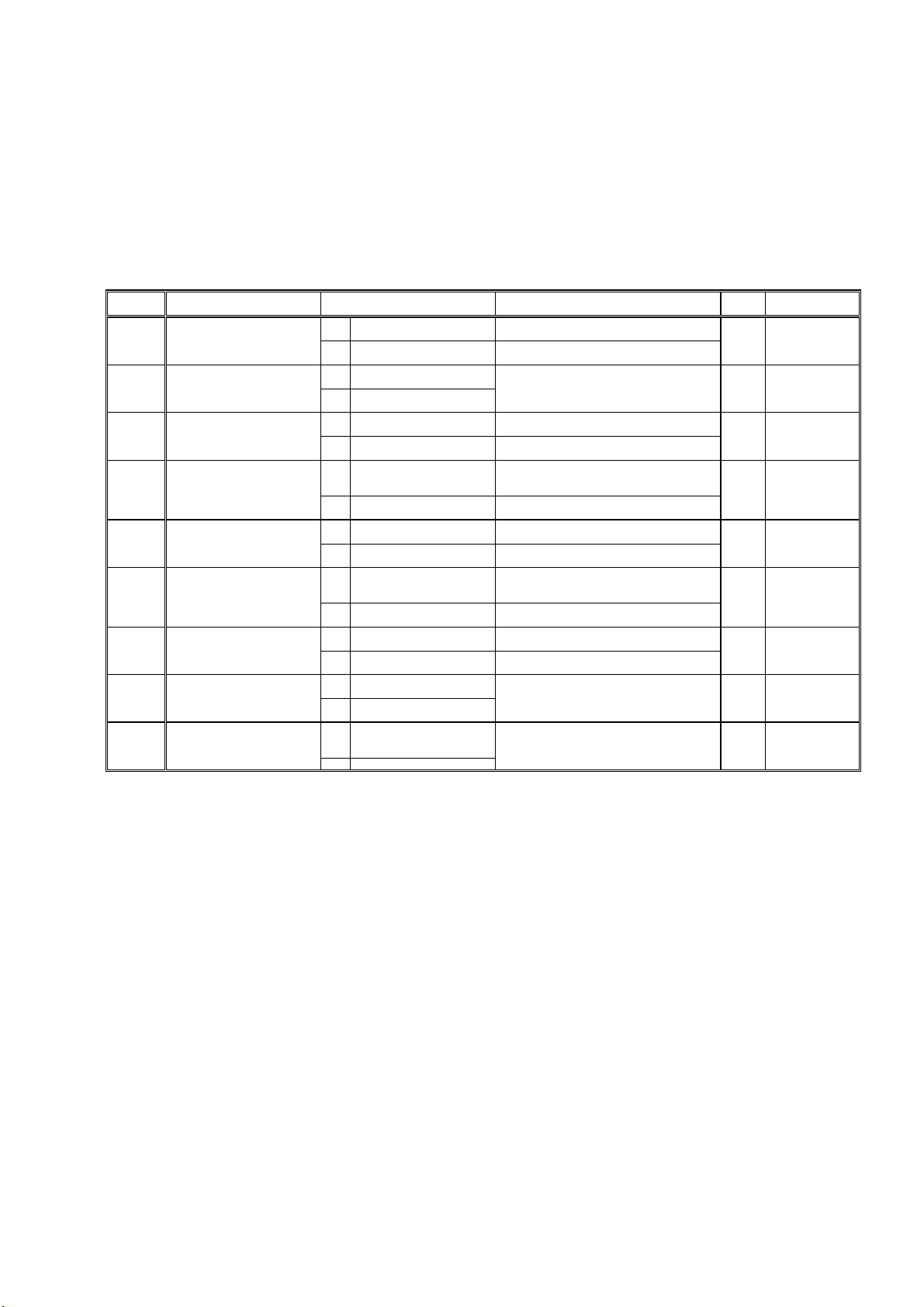
1-2.Explanation of Function Setting
This product requires a function setting switch because of the connected model, system configuration and control functions.
SW NO. switch name Function Note
SW1-1
SW1-2
SW1-3
SW1-4
SW1-5
SW1-7
SW1-8
SW1-9
SW3-2
Function switch of local prohibit ON local prohibit effective
Used together with MELAN
switch
Indoor temperature stat
interval switc
Reset Filtersign/Select
enable/disable operation duration
Function switch of LOSSNAY ON
Function switch of SNVT_switch ON SNVT standard
Select enable/disable force
thermostat OFF
Indoor units test run switch ON
Initialization switch of
the air conditioners units
Notes:
Always use together with the local remote controller or system controller.
*1:
*2: Always register the LM ADAPTER as a system controller when using together with the system controller.
*3: The functions used with the LM ADAPTER are changed. The air conditioner and LOSSNAY cannot be set to interlock with the LM ADAPTER.
Set with the system controller or local remote controller.
*4: Carry out an instruction input at the unit of the lowest address unit in the same group. The instructions to other units are disregarded.
However, a state output is output for every unit. Forced thermostat OFF needs an instruction input for every unit.
*5: Input the same instructions to all the units in the same group.
*6: Make a monitor interval into 1 minute, and when you use both the functions of "local prohibit", and the "forced thermostat OFF", give 25 sets or less.
Operation local prohibit NV input from
L
ONWORKS becomes Effective when switch ON
OFF local prohibit ineffective
ON used together with MELANS *4 OFF
not used together with MELAN
*2 OFF
*5
Transmission interva
ON
(1minutes or more
Transmission interva
OFF
(10 minutes or more
ON
effective
OFF ineffective
LOSSNAY is operate
from LONWORKS.
LOSSNAY interlock
*3 OFF
with indoor unit
OFF original
ON effective
OFF ineffective
ON (test run) is transmitted
to the indoor unit
OFF is transmitted
OFF
to the indoor unit
Connected cancellatio
ON
command is transmitted to
the indoor unit
OFF None
Operation local prohibit NV input fro
LONWORKS becomes invalid when switch OFF
*The number of indoor units connected should b
30 or less *6
When "ON",the reset filter sign input and the
operation duration output are enabled.
When "OFF",the reset filter sign input and th
operation duration output are disabled
Please turn on the switch when LOSSNA
is operated from LONWORKS.
Please turn off the switch when LOSSNA
interlocks with indoor units
When "ON",the specifications of the NV using the
SNVT_switch comply with the SNVT Standards.
When "OFF",the NV using the SNVT_switch ha
original specifications
When "ON",the forced thermo OFF NV input/outpu
are enabled
When "OFF",the forced thermo OFF N
input/output are disabled
03_NVspec_ver304e
Factory
setting
OFF
OFF
OFF
OFF
OFF
OFF
OFF Always
OFF Always
Set timing
Before turning on
the power suppl
Before turning o
the power suppl
Before turning o
the power suppl
Before turning on
the power supply
Before turning o
the power suppl
Before turning on
the power supply
Before turning o
the power suppl
WLN02-2124 - 2 -
Page 3
1-3.Functions
v
03_NVspec_ver304e
Operation Request All Off
Request On/Off
Request Mode
Setpoint
Request LOSSNAY Mode
Request FanSpeed
Request Local Prohibit On/Off
Request Local Prohibit Mode
Request Local Prohibit SetPoint
Request Collective Local Prohibit
Request Forced Thermostat OFF
Filter Sign Reset
Time Stamp
Request Limit Temperature Setting Range
Request Simplified Locking
Monitor Emergency state
Item
n
No.
Stops the operation of all air conditioners.
nv1
The ON/OFF operation is invalid during emergency stop.
nv1n Run and stop operation.
nv3n Sets the operation mode.
nv5n Sets the temperature.
nv7n Sets the LOSSNAY operation mode.
nv9n Sets the fan speed.
nv11n Sets the local remote controller to operation prohibit (On/Off).
nv13n Sets the local remote controller to operation prohibit (operation mode).
nv15n Sets the local remote controller to operation prohibit (temperature setting).
Sets the local remote controllers of all air conditioners to operation prohibit
nv4
(On/Off, operation mode, temperature setting).
nv17n Forcibly turns the air conditioner thermostat OFF.
nv19n The run time (for filter) of air conditioner is reset.
nv12 Sets the local remote controller time.
nv13 Sets the temperature setting range of local remote controller.
Sets the local remote controller switch's simple lock, and displays the mode and
nv14
intake temperature.
nv3 Output the emergency stop state.
Description
On/Off state
Collective On/Off state
Mode state
Setpoint State
LOSSNAY Mode State
FanSpeed state
Local Prohibit On/Off State
Local Prohibit Mode State
Local Prohibit SetPoint State
Collective Local Prohibit State
Forced Thermostat OFF State
Run Time for Filter
Space Temperature State
Defrost State
Group Number
Alarm State
Collective Alarm for Indoor Unit
Collective Alarm for LM ADAPTER
Error Code
nv2n Outputs the On/Off state.
nv2 Outputs the On/Off state for all air conditioners.
nv4n Outputs the operation mode setting state.
nv6n Outputs the temperature setting state.
nv8n Outputs the LOSSNAY operation mode setting state.
nv10n Outputs the fan speed setting state.
n12n Outputs the local remote controller operation prohibit (On/Off) state.
nv14n Outputs the local remote controller operation prohibit (operation mode) state.
Outputs the local remote controller operation prohibit (temperature setting)
nv16n
state.
nv5 Outputs the local remote controller collective operation prohibit state.
nv18n Outputs the forced thermostat OFF state.
nv20n Outputs the run time (for filter) of air conditioner.
nv21n Outputs the intake temperature of air conditioner.
nv9 Outputs the defrosting state of indoor unit or outdoor unit.
nv29n Outputs the group number of the indoor unit.
nv22n Outputs the presence of air conditioner errors.
nv6 Outputs the presence of errors in all air conditioners.
Outputs the presence of communication errors between the LM ADAPTER and
nv7
air conditioner.
nv23n Outputs the presence of air conditioner errors content (error code).
Error Address
Thermo On/Off state_1 (*1)
Thermo On/Off state_2 (*1)
Model Code (*1)
Note
*1: This product does not have a charge function.
The charge (apportioning) function must be prepared separately in the master system.
WSN02-2124 - 3 -
nv24n Outputs the error source (M-NET address) when an air conditioner error occurs.
nv25n Outputs the air conditioner operation, thermostat and auxiliary heater states.
nv26n Outputs the thermostat state.
nv28n Outputs the air conditioner model code.
Page 4
2
.Object Details
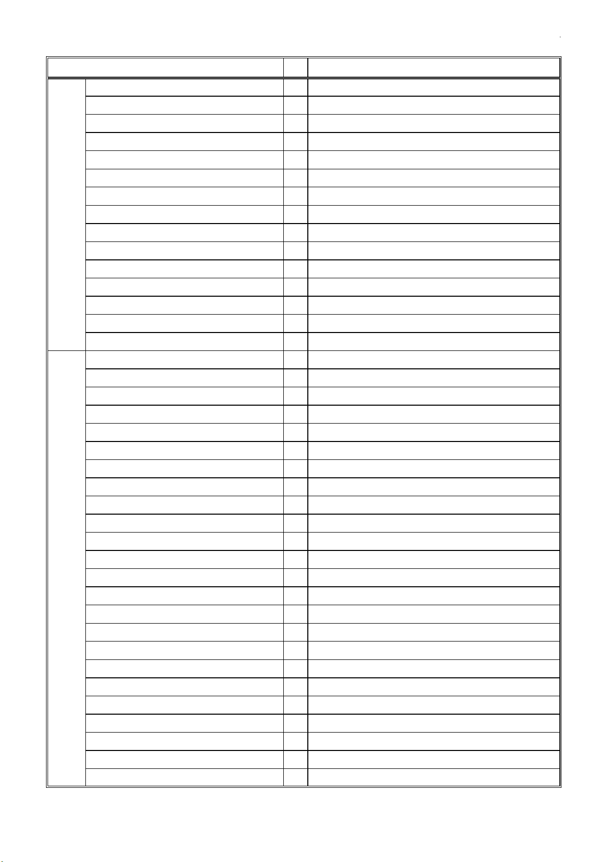
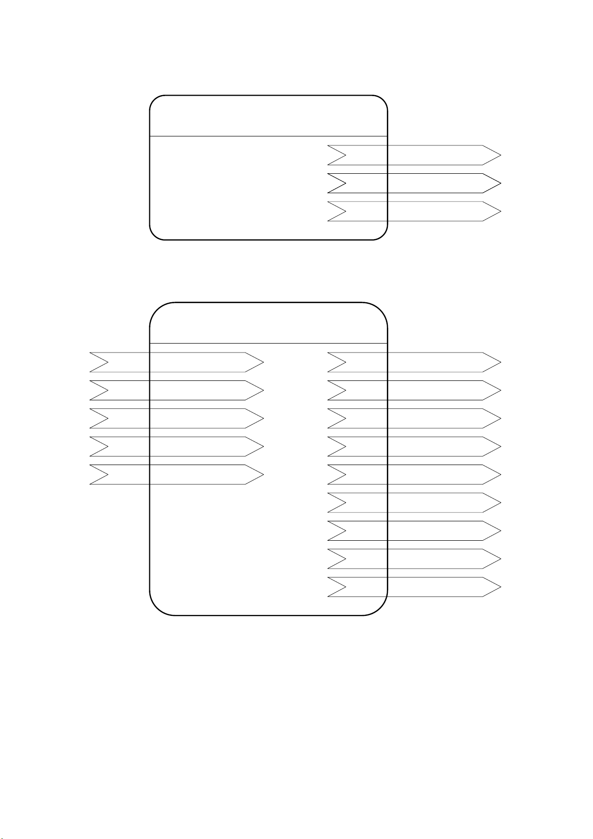
2-1.Overview
The LM adaptor has the node object, Indoor [0] and Indoor [1] to Indoor [50] objects. Each object contains the network variables
or configuration properties for all models.
Refer to each object (2.4 to 2.6) for the network variables that can be used with each model (unit).
03_NVspec_ver304e
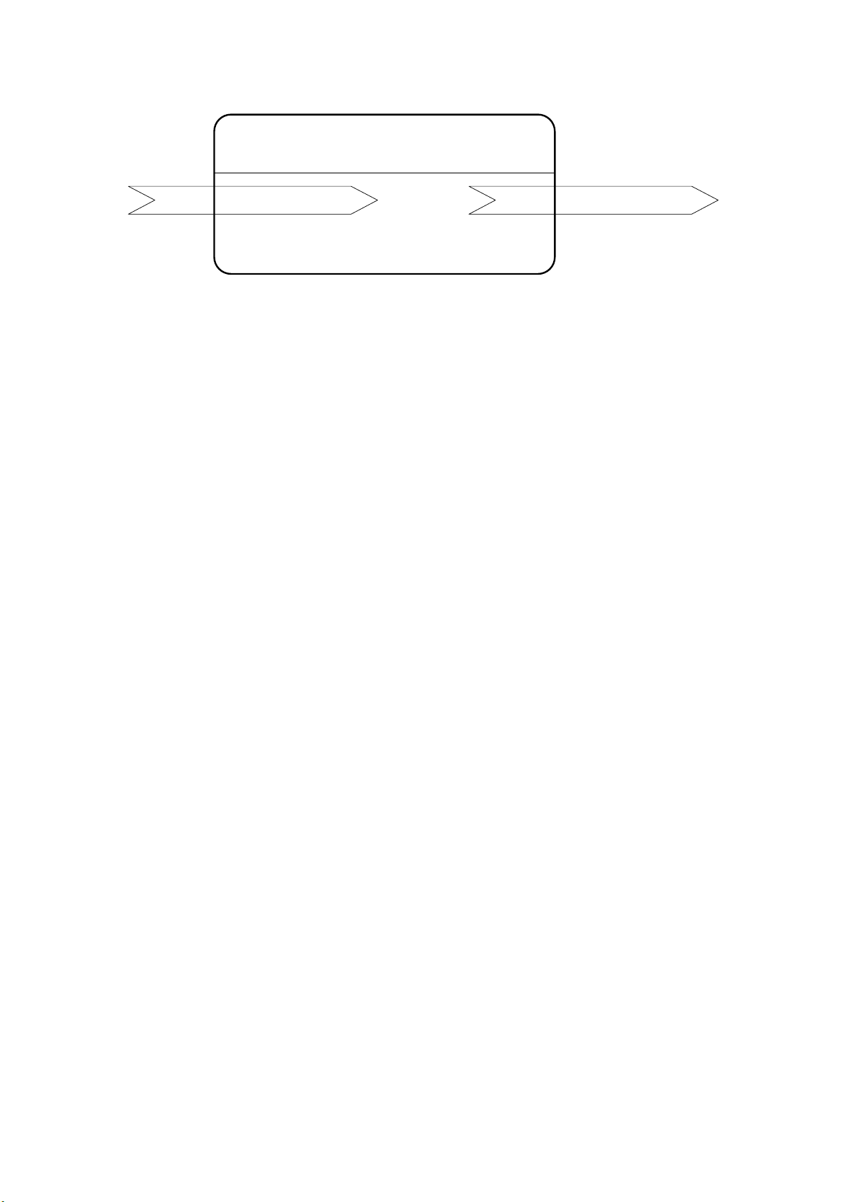
Node Object
Object Type #0
Network Variables
Indoor[0]
Network Variables
Configuration Properties
Indoor[1]
Network Variables
・
・
・
・
・
Indoor[50]
Network Variables
Node Object
Indoor[0]
Indoor[1]
Indoor[2]
::
Indoor[50]
WSN02-2124 - 4 -
Includes network variables of Node Object.
Includes collective network variables and configuration properties.
Includes network variables of 1st Indoor unit.
Includes network variables of 2nd Indoor unit.
Includes network variables of 50th Indoor unit.
Page 5
03_NVspec_ver304e
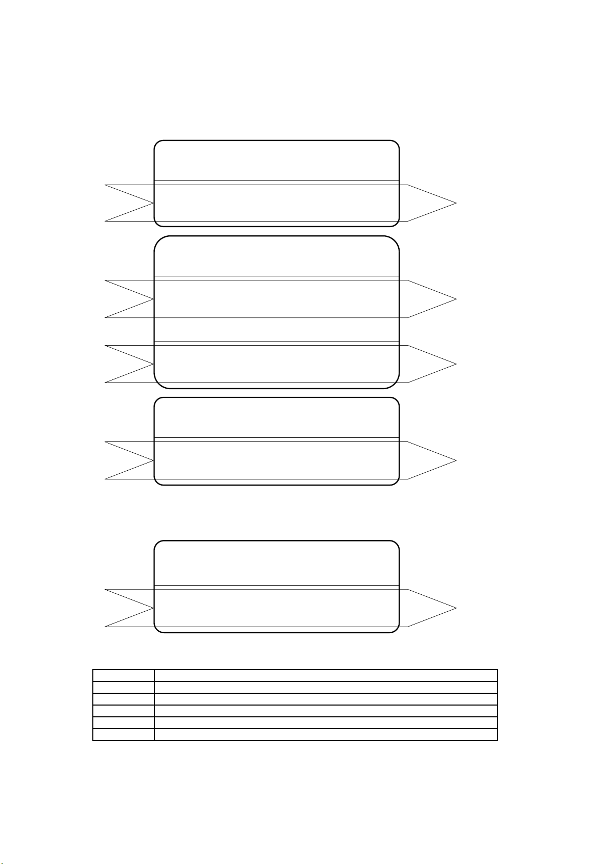
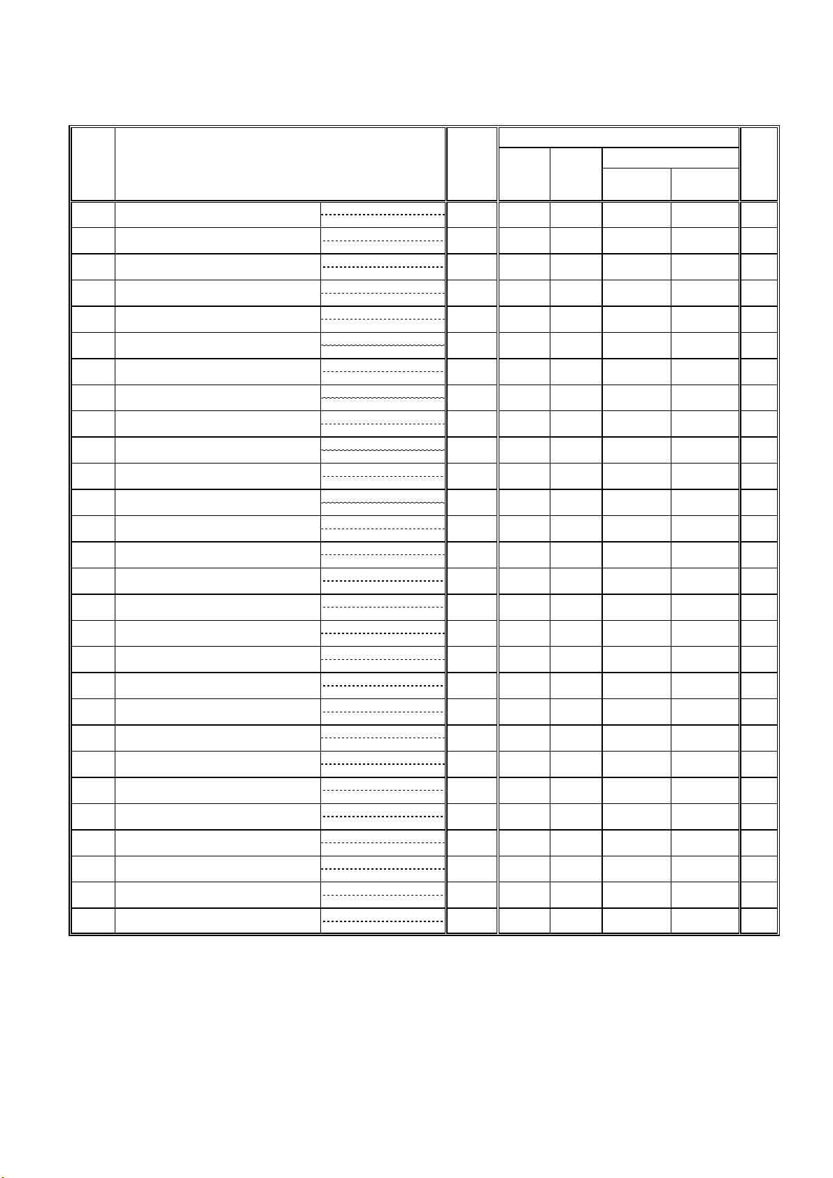
2-2.Node Object(*1
nv1
Note
SNVT_obj_request
stencil for LonMaker:Node Object
*1:
)
nviRequest
Node Object
Network Variables
nv2
nvoStatus
SNVT_obj_status
WSN02-2124 - 5 -
Page 6
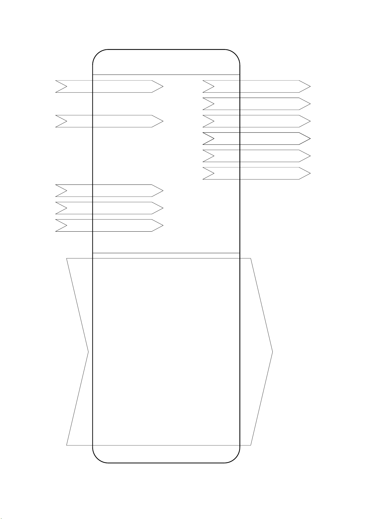
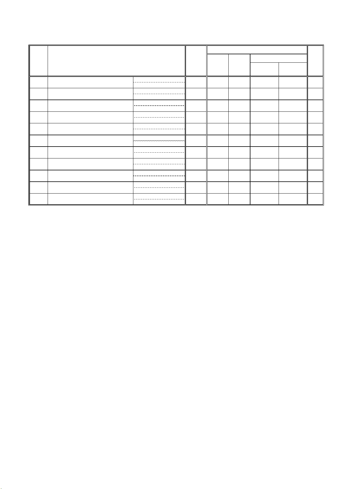
2-3.Collective operations/monitoring and Configuration Properties(*1)
Indoor[0]
Network Variables
03_NVspec_ver304e
(*3)
(*2)
(*2)
(*2)
nv1
nv4
nv12
nv13
nv14
nviAllOff
SNVT_switch
nviAllPro
SNVT_switch
nviRmTime
SNVT_time_stamp
nviRmLim
SNVT_switch
nviRmLck
SNVT_switch
Configuration Properties
nv2
nv3
nv5
nv6
nv7
nv9
nvoAllOnOff
SNVT_switch
nvoAllOff
SNVT_switch
nvoAllPro
SNVT_switch
nvoAllAlarm
SNVT_switch
nvoAllAlarmLMAP
SNVT_switch
nvoDefrost
SNVT_switch
(*3)
nciMinOutTm Minimum Send Time (nc15)
nciStartHrtBt Send Heartbeat Start Time (nc16)
nciStartOutTm Send Start Time (nc17)
nciInitStartTm Initialize Start Time (nc18)
nciInitOutTm_1 Initialize Send Time_1 (nc19)
nciInitOutTm_2 Initialize Send Time_2 (nc20)
nciSndHrtBt_1 Send Heartbeat_1 (nc21)
nciSndHrtBt_2 Send Heartbeat_2 (nc22)
nciAnalogWidth Spacetemp Width (nc23)
nciAnlgMonTm Monitoring Time (nc25)
nciRcvHrtBt_1 Receive Heartbeat_1 (nc26)
nciRcvHrtBt_2 Receive Heartbeat_2 (nc27)
nciEffectTm_1 Effective time_1 (nc28)
nciEffectTm_2 Effective time_2 (nc29)
nciPollFetch Effective PollFetch (mc30)
nciOffline Effective Offline Mode (nc31)
nciCoolLrSetP Lower Setpoint Cooling (nc34)
nciHeatUpSetP Upper Setpoint Heating (nc35)
nciRmOpLck Local Operation Lock (nc36)
nciRmDsp_1 Local Display_1 (nc37)
nciRmDsp_2 Local Display_2 (nc38)
nciSet_1 Communication Timing (nc39)
Notes
*1: stencil for LonMaker:Indoor[0]
*2: It is possible to use with an "ME" remote controller.
*3: It is possible to use with an "MA" remote controller.
WSN02-2124 - 6 -
Page 7
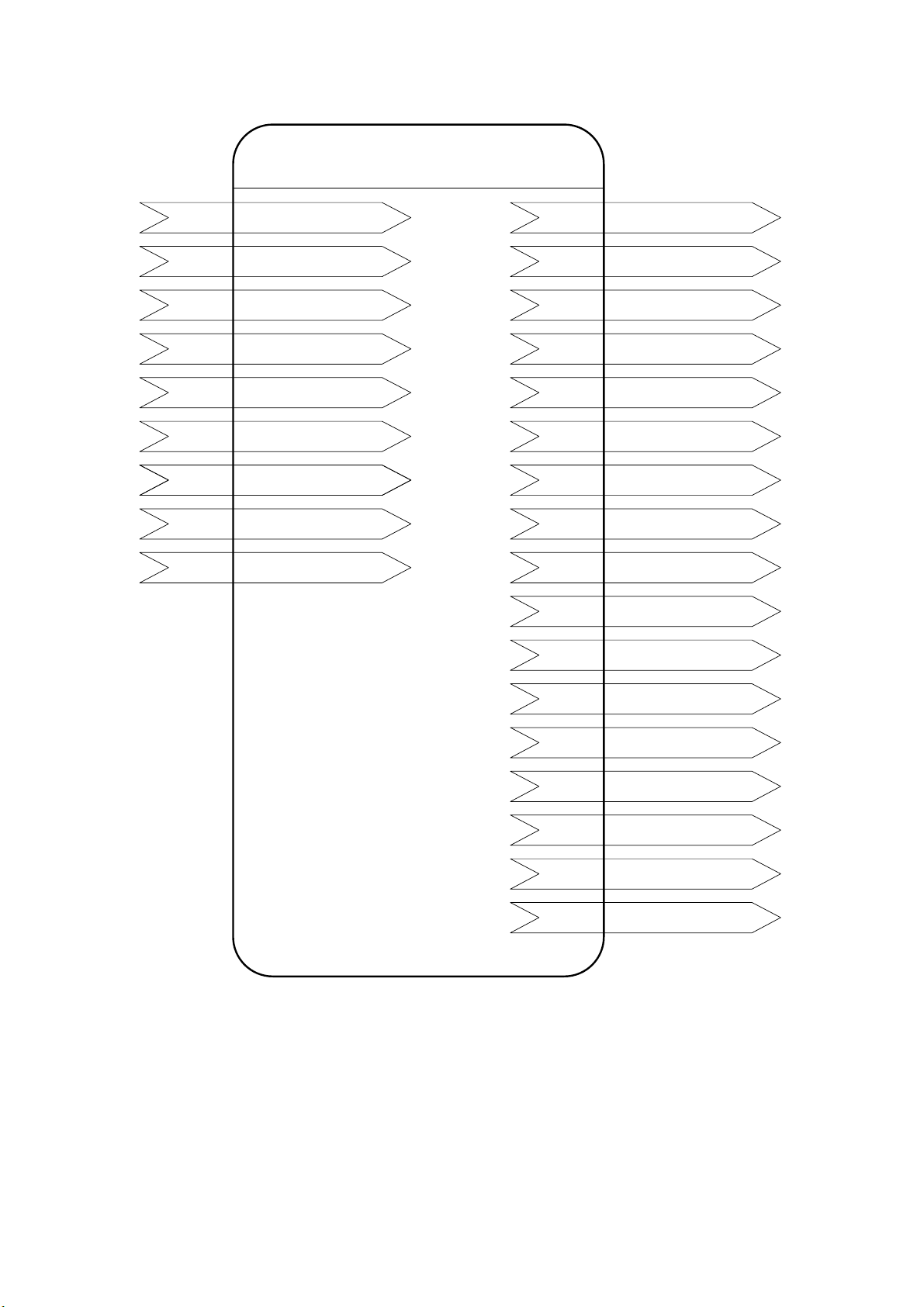
2-4.Indoor unit
03_NVspec_ver304e
Indoor[1]-[50]
Network Variables
nv1n
nv3n
nv5n
nv9n
(*3,4,5) nv11n
(*3,4,5) nv13n
(*3,4,5) nv15n
(*6) nv17n
(*7) nv19n
nviOnOff_n
SNVT_switch
nviMode_n
SNVT_hvac_mode
nviSetP_n
SNVT_temp_p
nviFanSpeed_n
SNVT_switch
nviProOnOff_n
SNVT_switch
nviProMode_n
SNVT_switch
nviProSetP_n
SNVT_switch
nviThermoOff_n
SNVT_switch
nviFiltReset_n
SNVT_switch
nv2n
nv4n
nv6n
nv10n
nv12n
nv14n
nv16n
nv18n
nv20n
nv21n
nv22n
nvoOnOff_n
SNVT_ switch
nvoMode_n
SNVT_hvac_mode
nvoSetP_n
SNVT_temp_p
nvoFanSpeed_n
SNVT_switch
nvoProOnOff_n
SNVT_switch
nvoProMode_n
SNVT_switch
nvoProSetP_n
SNVT_switch
nvoThermoOff_n
SNVT_switch
nvoOnTime_n
SNVT_time_hour
nvoSpaceTemp_n
SNVT_temp_p
nvoAlarm_n
SNVT_switch
(*3,4,5)
(*3,4,5)
(*3,4,5)
(*6)
(*7)
nv23n
nv24n
nv25n
nv26n
nv28n
nc29n
Notes
*1: stencil for LonMaker:Indoor[1]-[50]
*2: "n" of the network variable shows M-NET address of indoor units.
*3: It may be unable to be used by the system configuration of air-conditioners units.
*4: It is possible to use with an "MA" remote controller.
*5: For the use of this function, turn ON the switch(SW1-1) on LM ADAPTER.(Factory setting "OFF")
*6: For the use of this function, turn ON the switch(SW1-8) on LM ADAPTER.(Factory setting "OFF")
*7: For the use of this function, turn ON the switch(SW1-4) on LM ADAPTER.(Factory setting "OFF")
*8: It is possible to use with other system controller.
nvoErrCode_n
SNVT_count
nvoErrAdrs_n
SNVT_count
nvoThermoSt_n
SNVT_state
nvoThermo_n
SNVT_switch
nvoIcMdlSize_n
SNVT_count
nvoGroupNo_n
SNVT_count
(*8)
WSN02-2124 - 7 -
Page 8
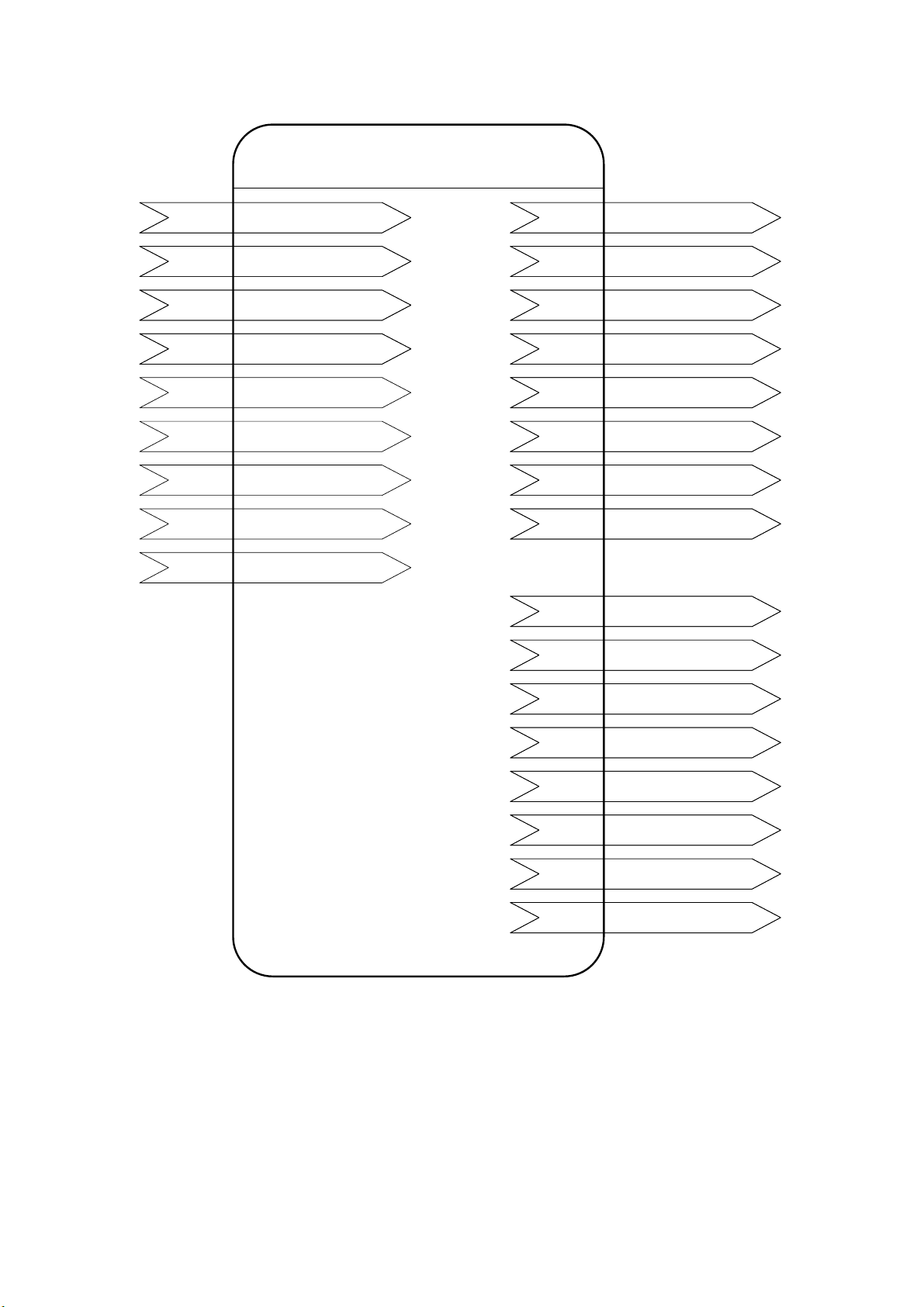
2-5.Mr.SLIM
03_NVspec_ver304e
Indoor[1]-[50]
Network Variables
nv1n
nv3n
nv5n
nv9n
(*3,4,5) nv11n
(*3,4,5) nv13n
(*3,4,5) nv15n
(*6) nv17n
(*7) nv19n
nviOnOff_n
SNVT_switch
nviMode_n
SNVT_hvac_mode
nviSetP_n
SNVT_temp_p
nviFanSpeed_n
SNVT_switch
nviProOnOff_n
SNVT_switch
nviProMode_n
SNVT_switch
nviProSetP_n
SNVT_switch
nviThermoOff_n
SNVT_switch
nviFiltReset_n
SNVT_switch
nv2n
nv4n
nv6n
nv10n
nv12n
nv14n
nv16n
nv18n
nv21n
nv22n
nvoOnOff_n
SNVT_ switch
nvoMode_n
SNVT_hvac_mode
nvoSetP_n
SNVT_temp_p
nvoFanSpeed_n
SNVT_switch
nvoProOnOff_n
SNVT_switch
nvoProMode_n
SNVT_switch
nvoProSetP_n
SNVT_switch
nvoThermoOff_n
SNVT_switch
nvoSpaceTemp_n
SNVT_temp_p
nvoAlarm_n
SNVT_switch
(*3,4,5)
(*3,4,5)
(*3,4,5)
(*6)
nv23n
nv24n
nv25n
nv26n
nv28n
nc29n
*1: stencil for LonMaker:MrSLIM[1]-[50]
*2: "n" of the network variable shows M-NET address of Mr.SLIM.
*3: It may be unable to be used by the system configuration of air-conditioners units.
*4: It is possible to use with an "MA" remote controller.
*5: For the use of this function, turn ON the switch(SW1-1) on LM ADAPTER.(Factory setting "OFF")
*6: For the use of this function, turn ON the switch(SW1-8) on LM ADAPTER.(Factory setting "OFF")
*7: For the use of this function, turn ON the switch(SW1-4) on LM ADAPTER.(Factory setting "OFF")
*8: It is possible to use with other system controller.
nvoErrCode_n
SNVT_count
nvoErrAdrs_n
SNVT_count
nvoThermoSt_n
SNVT_state
nvoThermo_n
SNVT_switch
nvoIcMdlSize_n
SNVT_count
nvoGroupNo_n
SNVT_count
(*8)
WSN02-2124 - 8 -
Page 9
2-6.LOSSNAY
(1)LOSSNAY interlocks with the indoor unit.(*1,3)
Indoor[1]-[50]
Network Variables
03_NVspec_ver304e
(2)LOSSNAY is operated from L
nv1n
(*4) nv7n
nv9n
ONWORKS.(*5,6,7)
nviOnOff_n
SNVT_switch
nviLCMode_n
SNVT_switch
nviFanSpeed_n
SNVT_switch
Indoor[1]-[50]
Network Variables
nv22n
nv23n
nv24n
nv2n
nv8n
nv10n
nvoAlarm_n
SNVT_switch
nvoErrCode_n
SNVT_count
nvoErrAdrs_n
SNVT_count
nvoOnOff_n
SNVT_ switch
nvoLCMode_n
SNVT_switch
nvoFanSpeed_n
SNVT_switch
(*4)
(*4)
(*8,9,10) nv11n
(*11) nv19n
Notes:
nviProOnOff_n
SNVT_switch
nviFiltReset_n
SNVT_switch
*1: stencil for LonMaker:iLOSSNAY[1]-[50]
*2: "n" of the network variable shows M-NET address of LOSSNAY.
*3: LOSSNAY is not controlled from a LONWORKS network.
*4: It may be unable to be used by the system configuration of air-conditioners units or the model of LOSSNAY.
*5: LOSSNAY is controlled from a LONWORKS network.
*6: stencil for LonMaker:LOSSNAY[1]-[50]
*7: Please turn ON the switch(SW1-5) when LOSSNAY is operation from LONWORKS.(Factory setting "OFF")
*8: There is a case which cannot be used with the system configuration of the air-conditioners units.
*9: It is possible to use with an "MA" remote controller.
*10: For the use of this function, turn ON the switch(SW1-1) on LM ADAPTER.(Factory setting "OFF")
*11: For the use of this function, turn ON the switch(SW1-8) on LM ADAPTER.(Factory setting "OFF")
*12: It is possible to use with other system controller.
nv12n
nv20n
nv22n
nv23n
nv24n
nc29n
nvoProOnOff_n
SNVT_switch
nvoOnTime_n
SNVT_time_hour
nvoAlarm_n
SNVT_switch
nvoErrCode_n
SNVT_count
nvoErrAdrs_n
SNVT_count
nvoGroupNo_n
SNVT_count
(*8,9,10)
(*11)
(*4)
(*12)
WSN02-2124 - 9 -
Page 10
03_NVspec_ver304e
3.SNVT Table
3-1.The network variables for individual operation/monitoring.
Model
nv No.
(*1)
1n
Request On/Off
2n
On/Off run state
3n
4n
Mode state
5n ○ (*6) ○ (*6)
SetPoint
6n ○ (*5) ○ (*5)
SetPoint state
7n
Request LOSSNAY Mode
8n
LOSSNAY Mode state
9n ○ (*6) ○ (*6)INRequest Fanspeed
10n ○ (*6) ○ (*6) ○ (*6)
FanSpeed state
11n ○ (*7,8) ○ (*7)
Request Local Prohibit On/Off
12n ○ (*7,8) ○ (*7)
Local Prohibit On/Off state
13n ○ (*7,8) ○ (*7)IN
Request Local Prohibit Mode
14n ○ (*7,8) ○ (*7)
Local Prohibit Mode state
15n ○ (*7,8) ○ (*7)
Request Local Prohibit SetPoint
16n ○ (*7,8) ○ (*7)
Local Prohibit SetPoint state
17n
Request Forced Thermostat OFF
18n
Forced Thermostat OFF state
19n Filter Sign Reset
20n
Filter Run Time
21n
Space Temperature
22n ○ (*2) ○ (*2) ○ (*2)
Alarm state
Error Code
23n ○ (*2) ○ (*2)
24n ○ (*2) ○ (*2) ○ (*2) ○ (*2)
Error Unit Address
25n
Thermo On/Off state_1
26n
28n Model Code OUT ○ (*4) ○ (*4) 28
29n ○ (*10) ○ (*10)OUTGroup Number
Notes:
*1: The value "n" is M-NET address of indoor unit
ex) Request On/Off to the 20th indoor unit.
nvNo :120
Name :nviOnOff_020
*2: The air conditioner maintenance error (minor fault) is not output.
*3: It may be unable to be used by the system configuration of air-conditioners units or the model of LOSSNAY.
*4: This is not output with LONWORKS network. Monitoring with Poll request or Fetch request is required.
*5: The monitor interval must be set in M-NET with the configuration properties (CP).
*6: The range (temperature setting, operation mode, wind speed setting) will differ according to the connected devices.
*7: It is possible to use with an "MA" remote controller (PAR-20MAU) .
*8: When some of the models marketed in July 2002 are used, either MA(PAR-20MAU) or ME(PAR-F27MEA-US) remote controller is required.
*9: The interlocked LOSSNAY is run and stopped with operations to each indoor unit.
*10: It is possible to use with other system controller.
Name (*1) I/O
nviOnOff_n
SNVT_switch
nvoOnOff_n
SNVT_switch
nviMode_n
SNVT_hvac_mode
nvoMode_n
SNVT_hvac_mode
nviSetP_n
SNVT_temp_p
nvoSetP_n
SNVT_temp_p
nviLCMode_n
SNVT_switch
nvoLCMode_n
SNVT_switch
nviFanSpeed_n
SNVT_switch
nvoFanSpeed_n
SNVT_switch
nvoProOnOff_n
SNVT_switch
nvoProOnOff_n
SNVT_switch
nviProMode_n
SNVT_switch
nvoProMode_n
SNVT_switch
nviProSetP_n
SNVT_switch
nvoProSetP_n
SNVT_switch
nviThermoOff_n
SNVT_switch
nvoThermoOff_n
SNVT_switch
nviFiltReset_n
SNVT_switch
nvoOnTime_n
SNVT_time_hour
nvoSpaceTemp_n
SNVT_temp_p
nvoAlarm_n
SNVT_switch
nvoErrCode_n
SNVT_count
nvoErrAdrs_n
SNVT_count
nvoThermoSt_n
SNVT_state
nvoThermo_n
SNVT_switch
nvoIcMdlSize_n
SNVT_count
nvoGroupNo_n
SNVT_count
IN
OUT
OUT
IN
OUT
IN
OUT
OUT
IN
OUT
OUT
IN
OUT
IN
OUT
IN
OUT
OUT
OUT
OUT
OUT
OUT
OUTThermo On/Off state_2
CITY
MULTI
○ (*6) ○ (*6)INRequest Mode
Mr.SLIM
○○
○○
○○
○○
○○
○○
○○
○○
○○
○○
interlocks with
the indoor unit
WSN02-2124
△ (*9)
△ (*9)
○ (*2)
○ (*2)
LOSSNAY
operation from
LonWorks
○ (*3)
○ (*3)
○ (*6)
○ (*7)
○ (*7)
○ (*2)
○ (*10)
Page.
○
○
○
14
14
15
15
16
16
17
17
18
18
19
19
20
20
21
21
22
22
23
23
24
25
25
26
27
27
29
- 10 -
Page 11
3-2.The network variables for collective operation/monitoring.
y
d
nv No.
(*1)
Request All Off
1
32Emergency state
Collective On/Off state
Request Collective Operation Prohibit
4 ○ (*2,3) ○ (*2)
Collective Local Prohibit state
5
Collective Alarm for Indoor Unit
6
Collective Alarm for LM Adapter
7 OUT
9 Defrost State OUT
Time Stamp
12 ○ (*5)
13 ○ (*4,5)
Request Limit Temperature Setting Range
14 ○ (*5)
Request Simplified Locking
Name (*1)
nviAllOff
SNVT_switch
nvoAllOff
SNVT_switch
nvoAllOnOff
SNVT_switch
nviAllPro
SNVT_switch
nvoAllPro
SNVT_switch
nvoAllAlarm
SNVT_switch
nvoAllAlarmLMAP
SNVT_switch
nvoDefrost
SNVT_switch
nviRmTime
SNVT_time_stamp
nviRmLim
SNVT_switch
nviRmLck
SNVT_switch
I/O
IN
OUT
OUT
IN
OUT
OUT
IN
IN
IN
CITY
MULTI
○○
○○
○○
○○
○○
○
○○
Mr.SLIM
○
03_NVspec_ver304e
Model
LOSSNAY
interlocks with
the indoor unit
○
○○
△ (*1)
○○
○○
operation from
LonWorks
○
○
Page.
30
30
31
32
32
33
33
34
34
35
35
*1: The interlocked LOSSNAY is run and stopped with operations to each indoor unit.
*2: It is possible to use with an "MA" remote controller (PAR-20MAU) .
*3: When some of the models marketed in Jul
for the local remote controller. (The M-NET small remote controller cannot be used.)
*4: The cool lower limit value and heat upper limit value must be set with the configuration properties (CP).
*5: ME remote control is used , and it can be used when an air-conditioning is a standard mode.
2002 are used, either the MA (PAR-20MAU) or ME (PAR-F27ME) remote controller can be use
WSN02-2124
- 11 -
Page 12
03_NVspec_ver304e
0(display) 4721 nc38
48
0(initialize)
46
46
46
43
43
44
41
41
42
39
39
40
36
37
37
38
6553.5 seconds (As 1800 seconds)2 nc16
6553.5 seconds(invalid)
40
6553.5 seconds (As 600.0 seconds)
6553.5 seconds (invalid)
-0.01℃(As 1.0℃)
42
0.0 second (As 1800.0 seconds)nc27
0.0 second (As 1800.0 seconds)
6553.5 seconds (As 600.0 seconds)
6553.5 seconds (As 600.0 seconds)
45
- 0.01℃(As 19℃)
0(disable) *Always effectivenc31
0(disable) *Always effective
- 0.01℃(As 28℃)
47
0(display)
0(All button)
Name Valid Range Unit, Default Page.
nc
No.
1.0 to 600.0 seconds 1sec
1200.0 to 6540.0 seconds 60sec
SNVT_time_sec
SNVT_time_sec
nciMinOutTm
nciStartHrtBt
SNVT_time_sec
SNVT_time_sec
nciStartOutTm
nciInitStartTm
0.0 second、0.1 to 1.0 seconds 0.1sec
SNVT_time_sec
SNVT_time_sec
nciInitOutTm_1
nciInitOutTm_2
nciSndHrtBt_1
10sec
0.0 second、600.0 to 6540.0 seconds 60sec
0.5 to 2.0℃ 0.5℃
SW1-3 is ON:0.0 second、60.0 to 6540.0 seconds
SW1-3 is OFF:0.0 second、600.0~6540.0 seconds
SNVT_time_sec
SNVT_temp_p
SNVT_time_sec
nciSndHrtBt_2
nciAnalogWidth
nc24
nc22 6553.5 seconds (invalid)
10sec
seconds
600.0 to 6540.0 seconds 60sec
SW1-3 is OFF:0.0 second、600.0 to 6540.0
SNVT_time_sec
SNVT_time_sec
nciAnlgMonTm
nciRcvHrtBt_1
nciRcvHrtBt_2
nc26
60sec
600.0 to 6540.0 seconds 60sec
60.0 to 600.0 seconds 60sec
60.0 to 6540.0 seconds
SNVT_time_sec
SNVT_time_sec
SNVT_time_sec
nciEffectTm_1
nciEffectTm_2
nc29
State=0(disable)、1(enable) --
State=0(Response)、1(non-response) --15
SNVT_switch
SNVT_switch
nciPollFetch
nciOffline
nc30
19.0℃ to 30.0℃ 1.0℃
17.0℃ to 28.0℃ 1.0℃
SNVT_temp_p
SNVT_temp_p
nciCoolLrSetP
nciHeatUpSetP
State=0(All button)、1(except Start/Stop button) --
State=0(display)、1(no display) --
SNVT_switch
SNVT_switch
nciRmOpLck
nciRmDsp_1
nc37
nc36
State=0(initialize)、1(setting time) --
State=0(display)、1(no display) --
SNVT_switch
SNVT_switch
nciRmDsp_2
nciSet_1
Description
Set the start time of network variable change at power ON.
Set the automatic update start time at power ON.
Set the start time of initial output change at power ON.
Set the minimum transmission interval between output network variables.
Item
Minimum Send Time
Send Heartbeat Start Time
3-3.Configuration Properties
1 nc15 6553.5 seconds (invalid)
Set the minimum transmission interval between output network variables
Initialize Send Time_1
3 nc17 6553.5 seconds (As 1800 seconds)1200.0 to 6540.0 seconds 60secSend Start Time
5 nc19 6553.5 seconds (invalid)
4 nc18 0.0 second、1200.0 to 3600.0 seconds 60secInitialize Start Time
at initial output.
Set the minimum transmission interval between each unit during initial
output.
Set the output network variable's update interval.
Set the output network variable's update interval.
Set the minimum fluctuation width of the output when the indoor
temperature state output changes.
Set the set time monitor interval of the indoor temperature for the indoor
unit.
Set the maximum elapse time from the previous update.
Set the maximum elapse time from the previous update.
Set the effective time for the emergency stop command.
Set the effective time for the collective operation prohibit command.
Set the presence of a response for poll (Fetch) requests in respect to the
output network variables.
Set the validity of the offline mode at power ON.
Spacetemp Width
Monitoring Time
Receive Heartbeat_1
Receive Heartbeat_2
Effective Time_1
Effective Time_2
Effective PollFetch
Initialize Send Time_2
6 nc20 6553.5 seconds (invalid)0.0 second、5.0 to 50.0 seconds 1.0sec
Send Heartbeat_2
Send Heartbeat_1
9
8
7 nc21
10 nc25
14
13 nc28
12
11
Effective Offline Mode
16
Set the cool/dry lower limit temperature setting value for the local remote
controller.
Set the heat upper limit temperature setting value for the local remote
controller.
Set the simple lock setting value for the local remote controller.
Set the validity of the automatic actual operation mode display for the local
Upper Setpoint Heating
Local Operation Lock
Local Display_1
18 nc35
17 nc34Lower Setpoint Cooling
19
20
Set the networks communication start timing.
remote controller.
Set the validity of the intake temperature display for the local remote
controller.
Local Display_2
Communication Timing
22 nc39
WSN02-2124 - 12 -
Page 13
03_NVspec_ver304e
p
g
p
Defrost
Collective
Collective
Alarm for LM
Alarm for
Collective
Local
Collective
Emergency
On/Off
Collective
Group
Number
Mode Code
Saving
Capacity
Thermo
On/Off 2
ADAPTER
Indoor Unit
Prohibit
Locking
Simplified
Limit
Range
Setting
Temperature
Time Stamp
Local
Prohibit
Collective
All Off
Reset
Filter Sign
OFF
Forced
Thermostat
Local
Prohibit
SetPoint
operation (request)
Local
Mode
Prohibit
Local
On/Off
Prohibit
Fanspeed
Mode
LOSSNAY
Thermo
On/Off 1
Address
Error Unit
monitoring (state)
Alarm Error Code
Space
Temperature
Time
Filter Run
OFF
Forced
Thermostat
Local
Prohibit
SetPoint
Local
Mode
Prohibit
Local
On/Off
Prohibit
FanSpeed
Mode
LOSSNAY
erties and Network Variables
uration Pro
nv1n nv3n nv5n nv7n nv9n nv11n nv13n nv15n nv17n nv19n nv1 nv4 nv12 nv13 nv14
ondence lists of Confi
3-4.The corres
Functions On/Off Mode SetPoint
nc15
nc16
nc17
nc18
Minimum Send Time
Send Heartbeat Start Time
Send Start Time
Initialize Start Time
1
2
3
4
nc19
nc20
nc21
nc22
Initialize Send Time_1
Initialize Send Time_2
Send Heartbeat_1
Send Heartbeat_2
5
6
7
8
nc24
nc25
nc26 ●●●
nc27 ●
nc28 ●
nc29 ●
Spacetemp Width
Monitoring Time
Receive Heartbeat_1
Receive Heartbeat_2
Effective time_1
9
10
Effective time_2
11
12
13
14
nc30
nc31
nc34 ●
Effective PollFetch
Effective Offline Mode
Lower Setpoint Cooling
15
16
17
nc35 ●
nc36 ●
nc37 ●●
nc38 ●●
nc39
Upper Setpoint Heating
Local Operation Lock
Local Display_1
Local Display_2
19
20
21
Communication Timing
22
18
nv2n nv4n nv6n nv8n nv10n nv12n nv14n nv16n nv18n nv20n nv21n nv22n nv23n nv24n nv25n nv26n nv27n nv28n nv29n nv2 nv3 nv5 nv6 nv7 nv9
nc15 ●●●●●●●●●● ●●● ●●●● ■■■■■■
nc16 ●●●●● ●
nc17 ●●●●●●●●●● ●●● ●●●● ●●●●●●
nc18 ● ● ● ●●●●●● ●● ●●
nc19 ● ● ● ●●●●●● ●● ●●●
nc20 ● ● ● ●●●●●● ●● ●●●
nc21 ●●●●●
nc22 ●
nc24 ●
nc25 ●
nc26
Functions On/Off Mode Setpoint
Minimum Send Time
Send Heartbeat Start Time
Send Start Time
Initialize Start Time
Initialize Send Time_1
Initialize Send Time_2
Send Heartbeat_1
Send Heartbeat_2
Spacetemp Width
Monitoring Time
1
2
3
4
5
6
7
8
9
10
Receive Heartbeat_1
11
nc27
nc28
nc29
nc30 ●●●●●●●●●● ●●● ●●●●● ● ● ●
Receive Heartbeat_2
Effective time_1
Effective time_2
Effective PollFetch
12
13
14
15
nc31 ●●●●●●●●●● ●●● ●●●●●●●●●●●●
nc34
nc35
nc36
nc37
nc38
nc39
Effective Offline Mode
Lower Setpoint Cooling
Upper Setpoint Heating
Local Operation Lock
Local Display_1
Local Display_2
Communication Timing
16
17
18
19
■:Effective between collective output variable.
20
21
22
WSN02-2124 - 13 -
Page 14
4.Network Variables
r
r
1n
Request On/Off
network input SNVT_switch nviOnOff_n;
This input network variable is used to run or stop the indoor unit or ventilator (during independent non-interlocked
operation).
When the ventilator (LOSSNAY) is registered as interlocking with indoor unit, it will turn the indoor unit ON (for
high speed) and OFF. Instructions according to this network variable in under nvoAllOff's output of the state of
"Emergency Off" are disregarded.
Valid Range
indoor unit interlocked ventilato
OFF
ON
Unit State
SW1-7:OFF
state value state value
OFF
ON(high) 0 100% (*1,3)
ON(high)
*1:The value field is set in 0% usually.
*2:The setting to state=0x02-0xFE is interpreted as state=0x01.
The setting to state=0xFF is invalid.
*3:The setting to over 100% is interpreted as 100%.
0
1
else
0% to 99.5 % (*1)
not used
not used
03_NVspec_ver304e
SW1-7:ON
0 not used
1 (*2) 0
1 (*2) 0.5% to 100% (*3)
Default Value
The default value is determined by the state of the air conditioner (indoor unit).
This variable becomes value = 0 until the value is updated after the power supply of LM ADAPTER.
2n
On/Off run state
network output SNVT_switch nvoOnOff_n;
This output network variable indicates the present On/Off state of the indoor unit or ventilator.
When the ventilator (LOSSNAY) is registered interlocking with the indoor unit, the state of the ventilator will not
be output, but it will operate (On/Off) the same as the indoor unit.
Valid Range
Unit State
indoor unit interlocked ventilato
OFF
ON
When Transmitted
This variable is transmitted promptly as its state changes.
This variable is also transmitted as the state changes by the operation from the local side such as a local
remote controller.
This variable is output by the ncilnitStartTm (Initialize Start Time) at the powering of LM ADAPTER.
SW1-7:OFF SW1-7:ON
state value state value
OFF 0 0%
ON(low) 0 50%
ON(high) 0 100%
any
10
00
1 100%
Update Rate
The value defined by nciSndHrtBt_1 (Send Heartbeat_1) and nciMinOutTm (Minimum Send Time) is valid.
Default Service Type
Acknowledged
WSN02-2124 - 14 -
Page 15
3n
Request mode
network input SNVT_hvac_mode nviMode_n;
This input network variable is used to change the operation mode of the indoor unit.
Some operation modes may not be compatible depending on the model.
Valid Range
value definition Active mode
0 HVAC_AUTO Auto mode
1 HVAC_HEAT Heat mode
3 HVAC_COOL Cool mode
5 HVAC_PRE_COOL Dry mode
9 HVAC_FAN_ONLY Fan mode
else - Fan mode
Default Value
The default value is determined by the state of the air conditioner (indoor unit).
This variable becomes value = 0 until the value is updated after the power supply of LM ADAPTER.
4n
Mode state
03_NVspec_ver304e
network output SNVT_hvac_mode nvoMode_n;
This output network variable indicates the present mode of the indoor unit.
Valid Range
value definition Active mode
0 HVAC_AUTO Auto mode
1 HVAC_HEAT Heat mode
3 HVAC_COOL Cool mode
5 HVAC_PRE_COOL Dry mode
9 HVAC_FAN_ONLY Fan mode
FF HVAC_NUL value not available
*The value is 0 while LM ADAPTER is initialized.
When Transmitted
This variable is transmitted promptly as the state changes.
This variable is also transmitted as the state changes by the operation from the local side such as a local
remote controller.
This variable is output by the ncilnitStartTm (Initialize Start Time) at the powering of LM ADAPTER.
Update Rate
The value defined by nciSndHrtBt_1 (Send Heartbeat_1) is valid.
Default Service Type
Acknowledged
NOTE:
1: It is necessary to make all the indoor units in the same refrigerant system into the same operation mode depending
on a model. "HVAC_NUL" may be outputted when it is set as different operation mode.
2: Depending on the change timing, "HVAC_NUL" may be outputted temporarily.
WSN02-2124 - 15 -
Page 16

5n
Setpoint
network input SNVT_temp_p nviSetPoint_n;
This input network variable is used to change the temperature setpoint of the indoor unit.
Valid Range
HVAC Mode Range
Auto mode 19℃ to 28℃
Heat mode 17℃ to 28℃
Cool mode 19℃ to 30℃
Dry mode 19℃ to 30℃
Fan mode Not available
Unit of set temperature : 1.0℃
*Be careful that the range of set temperature may differ depending on the model of the indoor and outdoor units.
Default Value
The default value is determined by the state of the air conditioner (indoor unit).
This variable becomes value = 0 until the value is updated after the power supply of LM ADAPTER.
6n
Setpoint state
03_NVspec_ver304e
network output SNVT_temp_p nvoSetPoint_n;
This output network variable indicates the present temperature setpoint of the indoor unit.
Valid Range
Output range: 17 to 30 ℃
Temperature unit: 1.0 ℃
*The value is 0 while LM ADAPTER is initialized.
When Transmitted
This variable is transmitted promptly as the state changes.
This variable is also transmitted as the state changes by the operation from the local side such as a local
remote controller.
This variable is output by the ncilnitStartTm (Initialize Start Time) at the powering of LM ADAPTER.
Update Rate
The value defined by nciSndHrtBt_1(SendHearbeat_1) is valid.
Default Service Type
Acknowledged
WSN02-2124 - 16 -
Page 17

7n
Request LOSSNAY Mode
network input SNVT_switch nviLCMode_n;
This input network variable is used to change the operation mode of the ventilator (at independent operation
without interlocking) .
This nv is not required to be use when setting the operation mode only from the local side such as a local
remote controller.
Valid Range
LOSSNAY Mode
Interchange 0 0
Automatic
03_NVspec_ver304e
SW1-7:OFF SW1-7:ON
state value state value
0 not used
1 (*1) 0
1 not used
else not used
1 (*1) 0.5% to 50%
Default Value
The default value is determined by the state of the ventilator.
This variable becomes value = 0 until the value is updated after the power supply of LM ADAPTER.
8n
LOSSNAY Mode state
network output SNVT_switch nvoLCMode_n;
This output network variable indicates the present operation mode of the ventilator.
Valid Range
LOSSNAY Mode
Interchange 0 0 0 0
Automatic 1 0 1 50%
Normal 0 100% 1 100%
*The value is 0 while LM ADAPTER is initialized.
0 0.5% to 100% (*2)Normal
*1:The setting to state=0x02-0xFE is interpreted as state=0x01.
The setting to state=0xFF is invalid.
*2:The setting to over 100% is interpreted as 100%.
SW1-7:OFF SW1-7:ON
state value state value
1 (*1) 50.5% to 100% (*2)
When Transmitted
This variable is transmitted promptly as the state changes.
It is also transmitted as the state changes by the operation from the local side such as a local remote controller.
Update Rate
The value defined by nciSndHrtBt_1 (Send Heartbeat_1) and nciMinOutTm (Minimum Send Time) is valid.
Default Service Type
Acknowledged
WSN02-2124 - 17 -
Page 18
9n
)
Request Fan Speed
network input SNVT_switch nviFanSpeed_n;
This input network variable is used to change the fan speed of the indoor unit or Ventilator (in case of
independent operation).
Valid Range
Fan Speed
Low 0% to 25%not used
Mid-2
Mid-1
High
* As the number of steps in fan speed differs depending on the model of the indoor unit.
Each indoor unit runs as follows. The data received is retained continually.
3-step model : Mid-2 is accepted as Mid-1.
2-step model : Mid-2 and Mid-1 are accepted as Low.
1-step model : Low, Mid-2 and Mid-1 are accepted as High.
03_NVspec_ver304e
SW1-7:OFF SW1-7:ON
state value state value
0 not used
1 (*1) 0
not used 25.5% to 50%
not used 50.5% to 75%
not used 75.5% to 100% (*2
*1:The setting to state=0x02-0xFE is interpreted as state=0x01.
The setting to state=0xFF is invalid.
*2:The setting to over 100% is interpreted as 100%.
1 (*1) 0.5% to 50%
1 (*1) 50.5% to 75%
1 (*1) 75.5% to 100% (*2)
Default Value
The default value is determined by the state of the air conditioner (indoor unit).
This variable becomes value = 0 until the value is updated after the power supply of LM ADAPTER.
10n
Fan Speed state
network output SNVT_switch nvoFanSpeed_n;
This output network variable indicates the present airflow rate of the indoor unit fan.
Valid Range
*The value is 0 while LM ADAPTER is initialized.
When Transmitted
This variable is transmitted promptly as the state changes.
It is also transmitted as the state changes by the operation from the local side such as a local remote controller.
Fan Speed
Low 0 25% 0 0
Mid-2 0 50% 1 50%
Mid-1 0 75% 1 75%
High 0 100% 1 100%
SW1-7:OFF SW1-7:ON
state value state value
Update Rate
The value defined by nciSndHrtBt_1(SendHearbeat_1) is valid.
Default Service Type
Acknowledged
WSN02-2124 - 18 -
Page 19

11n
:
:
:
:
Request Local Prohibit On/Off
network input SNVT_switch nviProOnOff_n;
This input network variable is used to prohibit the On/Off operation of the local remote controller connected
to the indoor unit or ventilator (under independent operation without interlocking).
When the ventilator is registered to be interlocked with the indoor unit, the On/Off operation of the ventilator
will also be prohibited.
Instructions according to this network variable in under the prohibition of collective operation (nvoAllPro outputs
"Enable") are held.
The operation prohibit setting will be cancelled when the time set with nciRcvHrtBt_1 (Receive Heartbeat 1) elapses ,
so periodic updating is required.
Valid Range
Prohibit/Permit
Permit
Prohibit
Default Value
The default value permit On/Off operation of local remote controller
This variable becomes value = 0 until the value is updated after the power supply of LM ADAPTER.
03_NVspec_ver304e
SW1-7:OFF SW1-7:ON
state value state value
0 not used 0 not used
else not used 1 (*1) 0
1 not used 1 (*1) 0.5% to 100% (*2)
*1:The setting to state=0x02-0xFE is interpreted as state=0x01.
The setting to state=0xFF is invalid.
*2:The setting to over 100% is interpreted as 100%.
NOTE:
1
For the use of this function, turn ON the switch (SW1-1) on LM ADAPTER.(Factory setting "OFF")
2
It is possible to use with an "MA" remote controller.
12n
Local Prohibit On/Off state
network output SNVT_switch nvoProOnOff_n;
This output network variable indicates the prohibit/permit state for the On/Off of the local remote controller
connected to the indoor unit or ventilator.
Valid Range
Prohibit/Permit
Permit 0 0 0 0
Prohibit 1 0 1 100%
*The value is 0 while LM ADAPTER is initialized.
When Transmitted
This variable is transmitted promptly as the state changes.
Update Rate
The maximum update rate is not available.
SW1-7:OFF SW1-7:ON
state value state value
Default Service Type
Acknowledged
NOTE:
1
For the use of this function, turn ON the switch (SW1-1) on LM ADAPTER.(Factory setting "OFF")
2
It is possible to use with an "MA" remote controller.
WSN02-2124 - 19 -
Page 20

13n
:
:
:
Request Local Prohibit Mode
network input SNVT_switch nviProMode_n;
This input network variable is used to prohibit the mode change operation of the local remote controller connected
to the indoor unit.
Instructions according to this network variable in under the prohibition of collective operation (nvoAllPro outputs
"Enable") are held.
The operation prohibit setting will be cancelled when the time set with nciRcvHrtBt_1 (Receive Heartbeat 1) elapses ,
so periodic updating is required.
Valid Range
Prohibit/Permit
Permit
Prohibit
Default Value
The default value permit mode change operation of local remote controller.
This variable becomes value = 0 until the value is updated after the power supply of LM ADAPTER.
03_NVspec_ver304e
SW1-7:OFF SW1-7:ON
state value state value
0 not used 0 not used
else not used 1 (*1) 0
1 not used 1 (*1) 0.5% to 100% (*2)
*1:The setting to state=0x02-0xFE is interpreted as state=0x01.
The setting to state=0xFF is invalid.
*2:The setting to over 100% is interpreted as 100%.
NOTE:
1
For the use of this function, turn ON the switch (SW1-1) on LM ADAPTER.(Factory setting "OFF")
2
It is possible to use with an "MA" remote controller.
14n
Local Prohibit Mode state
network output SNVT_switch nvoProMode_n;
This output network variable indicates the prohibit/permit state of the On/Off operation of the local remote
controller connected to the ventilator.
Valid Range
Prohibit/Permit
Permit 0 0 0 0
Prohibit 1 0 1 100%
*The value is 0 while LM ADAPTER is initialized.
When Transmitted
This variable is transmitted promptly as the state changes.
Update Rate
The maximum update rate is not available.
SW1-7:OFF SW1-7:ON
state value state value
Default Service Type
Acknowledged
NOTE:
1:For the use of this function, turn ON the switch (SW1-1) on LM ADAPTER.(Factory setting "OFF")
2
It is possible to use with an "MA" remote controller.
WSN02-2124 - 20 -
Page 21

15n
:
:
:
Request Local Prohibit SetPoint
network input SNVT_switch nviProSetP_n;
This input network variable is used to prohibit the temperature setpoint change of the local remote controller connected
to the indoor unit.
Instructions according to this network variable in under the prohibition of collective operation (nvoAllPro outputs
"Enable") are held.
The operation prohibit setting will be cancelled when the time set with nciRcvHrtBt_1 (Receive Heartbeat 1) elapses ,
so periodic updating is required.
Valid Range
Prohibit/Permit
Permit
Prohibit
Default Value
The default value permit temperature setpoint change for local remote controller.
This variable becomes value = 0 until the value is updated after the power supply of LM ADAPTER.
03_NVspec_ver304e
SW1-7:OFF SW1-7:ON
state value state value
0 not used 0 not used
else not used 1 (*1) 0
1 not used 1 (*1) 0.5% to 100% (*2)
*1:The setting to state=0x02-0xFE is interpreted as state=0x01.
The setting to state=0xFF is invalid.
*2:The setting to over 100% is interpreted as 100%.
NOTE:
1
For the use of this function, turn ON the switch (SW1-1) on LM ADAPTER.(Factory setting "OFF")
2
It is possible to use with an "MA" remote controller.
16n
Local Prohibit SetPoint state
network output SNVT_switch nvoProSetP_n;
This output network variable indicates the prohibit/permit of the temperature setting for the local remote controller
connected to the indoor unit or ventilator.
Valid Range
Prohibit/Permit
Permit 0 0 0 0
Prohibit 1 0 1 100%
*The value is 0 while LM ADAPTER is initialized.
When Transmitted
This variable is transmitted promptly as the state changes.
Update Rate
The maximum update rate is not available.
SW1-7:OFF SW1-7:ON
state value state value
Default Service Type
Acknowledged
NOTE:
1:For the use of this function, turn ON the switch (SW1-1) on LM ADAPTER.(Factory setting "OFF")
2
It is possible to use with an "MA" remote controller.
WSN02-2124 - 21 -
Page 22

17n
Request Forced Thermostat OFF
network input SNVT_switch nviThermoOff_n;
This input network variable is used to forcibly change indoor unit to the thermo OFF state (Fan mode).
The forced thermo OFF setting will be cancelled when the time set with nciRcvHrtBt_2 (Receive Heartbeat 2)
elapses, so periodic updating is required.
Valid Range
Thermostat OFF
disable
03_NVspec_ver304e
SW1-7:OFF SW1-7:ON
state value(*1) state value
0 1% to 100% (*3) 0 not used
else 1% to 100% (*3) 1 (*2) 0
0 0% to 0.5%
else 0% to 0.5%
1 not used
*1:The value field is set in 100% usually.
*2:The setting to state=0x02-0xFE is interpreted as state=0x01.
The setting to state=0xFF is invalid.
*3:The setting to over 100% is interpreted as 100%.
1 (*2)
0.5% to 100% (*3)enable
Default Value
The default value is determined by the state of the air conditioner (indoor unit).
This variable becomes value = 0 until the value is updated after the power supply of LM ADAPTER.
18n
Forced Thermostat OFF state
network output SNVT_switch nvoThermoOff_n;
This output network variable indicates the current forced thermo OFF state of the indoor unit.
Valid Range
Thermostat OFF
disable 0 0 0 0
enable 1 0 1 100%
*The value is 0 while LM ADAPTER is initialized.
When Transmitted
This variable is transmitted promptly as the state changes.
It is also transmitted as the state changes by the operation from the local side such as a local remote controller.
Update Rate
The maximum update rate is not available.
SW1-7:OFF SW1-7:ON
state value state value
Default Service Type
Acknowledged
WSN02-2124 - 22 -
Page 23

19n
Filter Sign Reset
network input SNVT_switch nviFiltReset_n;
This input network variable resets the run time and filter sign for the indoor unit or ventilator (during independent
non-interlocked operation).
Valid Range
*The value is 0 while LM ADAPTER is initialized.
*This operation is not carried out when there are inputs other than the above.
Default Value
This variable becomes value = 0 until the value is updated after the power supply of LM ADAPTER.
03_NVspec_ver304e
SW1-7:OFF SW1-7:ON
state value state value
Reset 1 not used 1(*1) 0.5% to 100% (*2)
*1:The setting to state=0x02-0xFE is interpreted as state=0x01.
The setting to state=0xFF is invalid.
*2:The setting to over 100% is interpreted as 100%.
20n
Filter Run Time
network output SNVT_time_hour nvoOnTime_n;
This output network variable indicates the filter operation time for the indoor unit or ventilator
(during independent non-interlocked operation).
Valid Range
0~65,534 hour
*The value is 0 while LM ADAPTER is initialized.
*The valid range will differ according to the indoor unit or ventilator model.
When Transmitted
This variable is transmitted promptly as the state changes.
Update Rate
The maximum update rate is not available.
Default Service Type
Acknowledged
NOTE: For the use of this function, turn ON the switch (SW1-4) on LM ADAPTER.(Factory setting "OFF")
WSN02-2124 - 23 -
Page 24

21n
:
:
Space Temperature
network output SNVT_temp_p nvoSpaceTemp_n;
This output network variable indicates the state of the indoor temperature.
Valid Range
Output range : -10 ~ 50℃
Temperature unit : 0.1℃
*The value is 0 while LM ADAPTER is initialized.
When Transmitted
This variable is transmitted when the indoor temperature changes by more than 1℃. (However , it will not be
transmitted for changes within 10 minutes.)
This variable is output when the state change is more than the change width set in nciAnalogWidth
(indoor temperature change width setting). (Note that changes within 10 minutes will not be output.)
*To obtain the output within 10 minutes, please refer to the nciSndHrtBt_2 (Send Heartbeat_2) and the
nciAnlgMonTm(Monitoring Time).
Update Rate
The value designated by nciSndHrtBt_2 (Send Heartbeat_2) and nciMinOutTm (Minimum Send Time) is valid.
Default Service Type
Acknowledged
03_NVspec_ver304e
NOTE:
1
Indoor temperature is outputted while an indoor unit stops. However,please usually use it for temperature
measurement only during operation. It may not become a normal value while a fan stops.
2
The display of local remote controller will be 1.0℃(below a decimal point round off) unit.
WSN02-2124 - 24 -
Page 25
22n
.
)
Alarm state
network output SNVT_switch nvoAlarm_n;
Valid Range
When Transmitted
Update Rate
03_NVspec_ver304e
This output network variable indicates the abnormality of the indoor unit.
If an error occurs in an outdoor unit, the indoor unit will also stop with an error. Thus, the error will be output
from all indoor units in the same refrigerant system. (However indoor units under stopping are excluded.)
Unit state
normal 0 0 0 0
alarm 1 0 1 100%
*The value is 0 while LM ADAPTER is initialized.
This variable is transmitted promptly as the state changes.
This variable is also transmitted as the state changes by the operation from the local side such as a local
remote controller.
This variable is output by the ncilnitStartTm (Initialize Start Time) at the powering of LM-AP.
The maximum update rate is not available.
SW1-7:OFF SW1-7:ON
state value state value
Default Service Type
NOTE:
1: The release of the indoor unit nvoAlarm_n(Alarm State) results in the "Off" command of the nviOnOff_n (Request On/Off)
2: The error is not output when the indoor unit is stopped, so always use together with the local remote controller
23n
Error Code
network output SNVT_count nvoErrCode_n;
Valid Range
When Transmitted
Acknowledged
For the nvoAlarm_n (Alarm State) when the indoor unit is under stopping, transmit "Off",after transmitting "On".
or system controller.
This output network variable indicates the indoor unit's error code.
If an error occurs in an outdoor unit, the indoor unit will also stop with an error. Thus, the error will be output
from all indoor units in the same refrigerant system. (However indoor units under stopping are excluded.)
0~7999 = Error Code
65,535 = Normal
*The value is 0 while LM ADAPTER is initialized.
This variable is transmitted promptly as the state changes.
This variable is also transmitted as the state changes by the operation from the local side such as a local
remote controller.
This variable is output by the ncilnitStartTm (Initialize Start Time) at the powering of LM ADAPTER.
Update Rate
The maximum update rate is not available.
Default Service Type
Acknowledged
NOTE:
1: The release of the indoor unit nvoErrCode_n(Error Code) results in the "Off" command of the nviOnOff_n(Request On/Off
For the nvoErrCode_n(Error Code) when the indoor unit is under stopping, transmit "Off" ,after transmitting "On".
2: The error is not output when the indoor unit is stopped, so always use together with the local remote controller
or system controller.
WSN02-2124 - 25 -
Page 26

24n
Error Unit Address
network output SNVT_count nvoErrAdrs_n;
This output network variable indicates the indoor unit's address.
If an error occurs in an outdoor unit, the indoor unit will also stop with an error. Thus, the error will be output
from all indoor units in the same refrigerant system. (However indoor units under stopping are excluded.)
Valid Range
0~255 = Error Unit Address
65,535 = Normal
*The value is 0 while LM ADAPTER is initialized.
When Transmitted
This variable is transmitted promptly as the state changes.
This variable is also transmitted as the state changes by the operation from the local side such as a local
remote controller.
This variable is output by the ncilnitStartTm (Initialize Start Time) at the powering of LM ADAPTER.
Update Rate
The maximum update rate is not available.
Default Service Type
Acknowledged
03_NVspec_ver304e
NOTE:
1: The release of the indoor unit nvoErrAdrs_n(Error Unit Address) results in the "Off" command
of the nviOnOff_n (Request On/Off).
For the nvoErrAdrs_n(Error Unit Address) when the indoor unit is under stopping, transmit "Off",after transmitting "On".
2: The error is not output when the indoor unit is stopped, so always use together with the local remote controller
or system controller.
WSN02-2124 - 26 -
Page 27
26n
Thermo On/Off state_1
network output SNVT_state nvoThermo_n;
This output network variable indicates the On/Off state of the indoor unit , the thermostat and the auxiliary
heater for heating.
This variable is used to calculate the electric charge.
Valid Range
bit[2] bit[1] bit[0] status
--
--
-
-
0
1
*The value is 0 while LM ADAPTER is initialized.
When Transmitted
This variable is transmitted promptly when the state changes.
This variable is output by the ncilnitStartTm (Initialize Start Time) at the powering of LM ADAPTER.
0 Indoor OFF
1 Indoor ON
0
1
--
--
-
-
Supplementary heater OFF
Supplementary heater ON
03_NVspec_ver304e
Indoor thermostat OFF
Indoor thermostat ON
Update Rate
The value designated by nciMinOutTm (Minimum Send Time) is valid.
Default Service Type
Acknowledged
NOTE: This output value is not the addition value or proportional division value of electric charge.
This variable outputs a value now. It is necessary to perform addition and proportional division based on this
output value.
26n
Thermo On/Off state 2
network output SNVT_switch nvoThermo_n;
This output network variable indicates the On/Off state of the indoor unit.
This variable is used to calculate the electric charge.
Valid Range
Thermostat State
Indoor thermostat OFF 0 0 0 0
Indoor thermostat ON 1 0 1 100%
*The value is 0 while LM ADAPTER is initialized.
SW1-7:OFF SW1-7:ON
state value state value
When Transmitted
This variable is transmitted promptly when the state changes.
This variable is output by the ncilnitStartTm (Initialize Start Time) at the powering of LM ADAPTER.
Update Rate
The value designated by nciMinOutTm (Minimum Send Time) is valid.
Default Service Type
Acknowledged
NOTE: This output value is not the addition value or proportional division value of electric charge.
This variable outputs a value now. It is necessary to perform addition and proportional division based on this
output value.
WSN02-2124 - 27 -
Page 28

28n
Model Code
network output SNVT_count nvoIcMdlSize_n;
Valid Range
When Transmitted
Update Rate
Default Service Type
03_NVspec_ver304e
This output network variable indicates the model code that indicates the indoor unit.
This variable is used to calculate the electric charge.
0~65,534
*The value is 0 while LM ADAPTER is initialized.
This variable is transmitted promptly when the state changes.
Monitoring with a Poll request or Fetch request is required.
The maximum update rate is not available.
Acknowledged
WSN02-2124 - 28 -
Page 29

29n
Group number
network output SNVT_count nvoGroupNo_n;
This output network variable indicates the group number of the indoor unit.
Valid Range
0~50
*The value is 0 while LM ADAPTER is initialized.
When Transmitted
This variable is transmitted promptly when the state changes.
Monitoring with a Poll request or Fetch request is required.
Update Rate
The maximum update rate is not available.
Default Service Type
Acknowledged
03_NVspec_ver304e
NOTE: The group number set up by the system controller is outputted.
WSN02-2124 - 29 -
Page 30

1
Request All Off
network input SNVT_switch nviAllOff;
This input network variable is used for the emergency Off of the indoor unit and all ventilation.
Under the output of "Emergency OFF" of nvoAllOff cannot operate from other remote controller ,system controller.
The ON/OFF input for each indoor unit from the master system will be ignored. The emergency stop valid time is
set with nciEffectTm_1 (Effective time 1).
The indoor unit will not start even if the emergency stop is cancelled.
Valid Range
emergency OFF
*This operation is not carried out when there are inputs other than the above.
The present instruction state is continued.
Default Value
This variable become state=0 and value = 0 until the value is updated after the power supply of LM ADAPTER.
03_NVspec_ver304e
SW1-7:OFF SW1-7:ON
state value state value
0 not used
*1:The setting to state=0x02-0xFE is interpreted as state=0x01.
The setting to state=0xFF is invalid.
0 not used
1 (*1) 0
NOTE: Input the "On" command with nviOnOff (Request ON/OFF) to start the indoor unit after emergency stop is cancelled.
3
Emergency state
network output SNVT_switch nvoAllOff;
This output network variable indicates the emergency stop validity state.
Valid Range
Emergency state
normal 0 0 0 0
Emergency OFF 1 0 1 100%
*The value is 0 while LM ADAPTER is initialized.
SW1-7:OFF SW1-7:ON
state value state value
When Transmitted
This variable is transmitted promptly when the state changes.
This variable is output by the ncilnitStartTm (Initialize Start Time) at the powering of LM ADAPTER.
Update Rate
This network variable is outputted every 10 minutes.
Default Service Type
Acknowledged
WSN02-2124 - 30 -
Page 31

2
Collective On/Off state
network output SNVT_switch nvoAllOnOff;
This output network variable collectively indicates the current On/Off state of the indoor units or ventilators
(during independent non-interlocked operation).
Valid Range
Collective Unit state
All Off 0 0% to 100% 0 0
One or more sets are ON or in test run
*The value is 0 while LM ADAPTER is initialized.
When Transmitted
This variable is transmitted promptly when the state changes.
It is also transmitted as the state changes by the operation from the local side such as a local remote controller.
This variable is output by the ncilnitStartTm (Initialize Start Time) at the powering of LM ADAPTER.
Update Rate
The maximum update rate is not available.
03_NVspec_ver304e
SW1-7:OFF SW1-7:ON
state value state value
1 0% to 100% 1 100%
Default Service Type
Acknowledged
WSN02-2124 - 31 -
Page 32

4
:
:
:
Request Collective Operation Prohibit
network input SNVT_switch nviAllPro;
This input network variable is used to collectively prohibit (On/Off, operation mode, temperature setting operations)
of the local remote controller connected to the indoor unit or ventilator (during independent non-interlocked operation).
Instructions according to nviProOnOff_n,nviProMode_n,and nviProSetP_n, in under the prohibition of collective operation
(nvoAllPro outputs "Enable") are held.
The effective time is set according to nviEffectTm_2(Effective Time_2).
Valid Range
Collective Operation Prohibit
Enable
*This operation is not carried out when there are inputs other than the above.
The present instruction state is continued.
state value state value
1 not used 1 (*1) 0.5% to 100% (*2)
*1:The setting to state=0x02-0xFE is interpreted as state=0x01.
The setting to state=0xFF is invalid.
*2:The setting to over 100% is interpreted as 100%.
Default Value
This variable become state=0 and value = 0 until the value is updated after the power supply of LM ADAPTER.
03_NVspec_ver304e
SW1-7:OFF SW1-7:ON
NOTE:
1:For the use of this function, turn ON the switch (SW1-1) on LM ADAPTER.(Factory setting "OFF")
2
It is possible to use with an "MA" remote controller.
5
Collective Local Prohibit state
network output SNVT_switch nvoAllPro;
This output network variable indicates the state of collective operation prohibiting.
Valid Range
Collective Local Prohibit
disable 0 0 0 0
enable 1 0 1 100%
*The value is 0 while LM ADAPTER is initialized.
SW1-7:OFF SW1-7:ON
state value state value
When Transmitted
This variable is transmitted promptly when the state changes.
Update Rate
The maximum update rate is not available.
Default Service Type
Acknowledged
NOTE:
1
For the use of this function, turn ON the switch (SW1-1) on LM ADAPTER.(Factory setting "OFF")
2
It is possible to use with an "MA" remote controller.
WSN02-2124 - 32 -
Page 33

6
t
R
Collective Alarm for Indoor Uni
network output SNVT_switch nvoAllAlarm;
This output network variable collectively outputs the presence of indoor unit errors(nvoAlarm_n).
Abnormalities will be output if the number of the indoor units in unusual is included.
Valid Range
normal 0 0 0 0
Error 1 0 1 100%
*The value is 0 while LM ADAPTER is initialized.
When Transmitted
This variable is transmitted promptly when the state changes.
This variable is output by the ncilnitStartTm (Initialize Start Time) at the powering of LM ADAPTER.
Update Rate
The maximum update rate is not available.
03_NVspec_ver304e
SW1-7:OFF SW1-7:ON
state value state value
Default Service Type
Acknowledged
7
Collective Alarm for LM ADAPTE
network output SNVT_switch nvoAllAlarmLMAP;
This output network variable collectively outputs the presence of communication errors between the LM ADAPTER
and indoor unit.
If the number of the indoor units in communication is unusual, the abnormalities in communication will be output.
Valid Range
LM ADAPTER state
Normal 0 0 0 0
communication Error 1 0 1 100%
*The value is 0 while LM ADAPTER is initialized.
When Transmitted
This variable is transmitted promptly when the state changes.
This variable is output by the ncilnitStartTm (Initialize Start Time) at the powering of LM-AP.
Update Rate
The maximum update rate is not available.
SW1-7:OFF SW1-7:ON
state value state value
Default Service Type
Acknowledged
NOTE: The communication error are caused with the power supply OFF of an outdoor unit etc.
With the power supply OFF of an indoor unit, communication does not become unusual.
WSN02-2124 - 33 -
Page 34

9
Collective Defrosting State
network output SNVT_switch nvoDefrost;
This network variable indicated the defrosting state (collective) of indoor unit and outdoor unit.
Valid Range
unit state
Normal 0 0 0 0
defrosting 1 0 1 100%
*The value is 0 while LM ADAPTER is initialized.
When Transmitted
This variable is transmitted promptly when the state changes.
Update Rate
The maximum update rate is not available.
03_NVspec_ver304e
SW1-7:OFF SW1-7:ON
state value state value
Default Service Type
Acknowledged
12
Time Stamp
network input SNVT_time_stamp nviRmTime;
This input network variable sets the local remote controller's time.
The time is collectively set for all remote controllers (for which the time can be set) connected to M-NET.
Valid Range
year not used(0:constantly)
month not used(0:constantly)
day not used(0:constantly)
hour 0 to 23
minute 0 to 59
second 0 to 59
Default Value
The value is 0 while LM ADAPTER is initialized.
NOTE: The time is reset when the local remote controller's power is turned OFF, so the time must be set periodically.
WSN02-2124 - 34 -
Page 35
13
:
:
:
:
Request Limit Temperature Setting Range
network input SNVT_switch nviRmLim;
This input network variable changes the local remote controller's temperature setting range.
The set temperature range is set with nciCoolLrSetP (cool/dry lower limit value setting), and nciHeatUpSetP
(Upper Setpoint Heating).
The displayed details are set with nciRmDsp_1 (Local Display 1) and nciRmDsp_2 (Local Display 2).
Valid Range
Change of the setting Range
disable
enable
* The details displayed on the local remote controller will be set at each update regardless of the "state field" value.
state value state value
0 not used
else not used
1 not used
*1:The setting to state=0x02-0xFE is interpreted as state=0x01.
The setting to state=0xFF is invalid.
*2:The setting to over 100% is interpreted as 100%.
Default Value
A default value is determined by the setting value of local remote controller.
This variable become state=0 and value = 0 until the value is updated after the power supply of LM ADAPTER.
03_NVspec_ver304e
SW1-7:OFF SW1-7:ON
0 not used
1 (*1) 0
1 (*1) 0.5% to 100% (*2)
NOTE:
1
It is possible to use with an "MA" remote controller.
2
The range is set collectively for all remote controllers (for which range can be set) connected to M-NET.
14
Request Simplified Locking
network input SNVT_switch nviRmLck;
This input network variable sets the simple lock for the local remote controller operations.
The simple lock range is set with nciRmOpLck (Local Operation Lock).
The displayed details are set with nciRmDsp_1 (Local Display 1) and nciRmDsp_2 (Local Display 2).
The simple lock is set collectively for all remote controllers (for which simple lock can be set) connected to M-NET.
Valid Range
Change of the Simplified Locking
disable
enable
* The details displayed on the local remote controller will be set at each update regardless of the "state field" value.
Default Value
A default value is determined by the setting value of local remote controller.
This variable become state=0 and value = 0 until the value is updated after the power supply of LM ADAPTER.
SW1-7:OFF SW1-7:ON
state value state value
0 not used
else not used
1 not used
*1:The setting to state=0x02-0xFE is interpreted as state=0x01.
The setting to state=0xFF is invalid.
*2:The setting to over 100% is interpreted as 100%.
0 not used
1 (*1) 0
1 (*1) 0.5% to 100% (*2)
NOTE:
1
It is possible to use with an "MA" remote controller.
2
The range is set collectively for all remote controllers (for which range can be set) connected to M-NET.
WSN02-2124 - 35 -
Page 36

5.Configuration Properties
15
Minimum Send Time
network input config SNVT_time_sec nciMinOutTm;
This configuration property defines the minimum send time between the output network variables.
The objective network variables are given below.
Transmitting time is secured per indoor unit.
・nvoOnOff_n(On/Off run state)
・nvoMode_n(Mode state)
・nvoSetP_n(SetPoint state)
・nvoLCMode_n(LOSSNAY Mode state)
・nvoFanSpeed_n(FanSpeed state)
・nvoProOnOff_n(Local Prohibit On/Off state)
・nvoProMode_n(Local Prohibit Mode state)
・nvoProSetP_n(Local Prohibit SetPoint state)
・nvoThermoOff_n(Forced Thermostat OFF state)
・nvoOnTime_n(Filter Run Time)
・nvoSpaceTemp_n(Space Temperature)
・nvoAlarm_n(Alarm state)
・nvoErrCode_n(Error Code)
・nvoErrAdrs_n(Error Unit Address)
・nvoThermoSt_n(Thermo On/Off state_1)
・nvoThermo_n(Thermo On/Off state_2)
03_NVspec_ver304e
Transmitting time is secured per indoor unit.
・nvoAllOnOff(Collective On/Off state)
・nvoAllOff(Emergency state)
・nvoAllPro(Collective Local Prohibit state)
・nvoDefrost(Collective Defrosting state)
・nvoAllAlarm(Collective Alarm for Indoor Unit)
・nvoAllAlarmLMAP(Collective Alarm for LM ADAPTER)
Valid Range
The valid range covers from 1.0 to 600.0 seconds (per 1 second).
The setting to 0.0 or 6553.5 seconds makes the minimum send time setting invalid.
The setting to 0.1 - 0.9 seconds results in 1.0 second.
The setting to 600.1 - 6553.4 seconds results in 600.0 seconds.
Default Value
6553.5 seconds (Setting invalid)
WSN02-2124 - 36 -
Page 37

16
_
_
g
Send Heartbeat Start Time
network input config SNVT_time_sec nciStartHrtBt
This configuration property defines the start time of automatic updating at the powering of the LM ADAPTER.
The objective configuration properties are given below.
・nciSndHrtBt
・nciSndHrtBt
1(Send Heartbeat_1)
2(Send Heartrbeat_2)
Valid Range
The valid range covers from 1200.0 to 6540.0 seconds (per 60 seconds).
The setting to 0.0 or 6553.5 seconds results in 1800.0 seconds.
The setting to 0.1 - 1199.9 seconds results in 1200.0 seconds.
The setting to 6540.1- 6553.4 seconds results in 6540.0 seconds.
Default Value
6553.5 seconds (judged as 1800 seconds)
17
Send Start Time
network input config SNVT_time_sec nciStartOutTm
This configuration property defines the start time of the output network variable change at powering of LM ADAPTER.
The objective network variables are given below.
・nvoOnOff_n(On/Off run state)
・nvoMode_n(Mode state)
・nvoSetP_n(SetPoint state)
・nvoLCMode_n(LOSSNAY Mode state)
・nvoFanSpeed_n(Fanspeed state)
・nvoProOnOff_n(Local Prohibit On/Off state)
・nvoProMode_n(Local Prohibit Mode state)
・nvoProSetP_n(Local Prohibit SetPoint state)
・nvoThermoOff_n(Forced Thermostat OFF state)
・nvoOnTime_n(Filter Run Time)
・nvoSpaceTemp_n(Space Temperature)
・nvoAlarm_n(Alarm state)
・nvoErrCode_n(Error Code)
・nvoErrAdrs_n(Error Unit Address)
・nvoThermoSt_n(Thermo On/Off state_1)
・nvoThermo_n(Thermo On/Off state_2)
・nvoAllOnOff(Collective On/Off state)
・nvoAllOff(Emergency state)
・nvoAllPro(Collective local prohibit state)
・nvoDefrost(Collective Defrosting state)
・nvoAllAlarm(Collective Alarm for Indoor Unit)
・nvoAllAlarmLMAP(Collective Alarm for LM ADAPTER)
03_NVspec_ver304e
Valid Range
The valid range covers from 1200.0 to 6540.0 seconds (per 60 seconds).
The setting to 0.0 or 6553.5 seconds results in 1800.0 seconds.
The setting to 0.1 - 1199.9 seconds results in 1200.0 seconds.
The settin
to 6540.1 ~ 6553.4 seconds results in 6540.0 seconds.
Output data is as follows by setup of Variable A and Variable B.
Default Value
6553.5 seconds (judged as 1800 seconds)
NOTE: Output data is as follows by setup "Initialize Start Time" and "Communication Timing".
Setting "Initialize":
An initial output value or a value at a power supply ON to the time of 20-minute progress.
Setting "setting time":
An initial output value or a value at the time of Neuron Chip communication start.
WSN02-2124 - 37 -
Page 38

18
g
Initialize Start Time
network input config SNVT_time_sec nciInitStartTm
This configuration property defines the time to start the output when the output network variables change
at LM ADAPTER power ON.
The objective network variables are given below.
・nvoOnOff_n(On/Off run state)
・nvoMode_n(Mode state)
・nvoSetP_n(SetPoint state)
・nvoAlarm_n(Alarm state)
・nvoErrCode_n(Error Code)
・nvoErrAdrs_n(Error Unit Address)
・nvoThermoSt_n(Thermo On/Off state_1)
・nvoThermo_n(Thermo On/Off state_2)
・nvoAllOnOff(Collective On/Off state)
・nvoAllOff(Emergency state)
・nvoAllAlarm(Collective Alarm for Indoor Unit)
・nvoAllAlarmLMAP(Collective Alarm for LM ADAPTER)
Valid Range
The valid range covers from 0.0,1200.0 to 3600.0 seconds (per 60 seconds).
The setting to 0.0 or 6553.5 seconds makes the initial output time setting invalid.
The setting to 0.1 - 1199.9 seconds results in 1200.0 seconds.
The settin
to 3600.1 ~ 6553.4 seconds results in 3600.0 seconds.
03_NVspec_ver304e
Default Value
6553.5 seconds (Setting invalid)
WSN02-2124 - 38 -
Page 39

19
Initialize Send Time_1
network input config SNVT_time_sec nciInitOutTm_1
This configuration property defines the minimum send time between the output network variables at initial output.
This configuration is valid when setting the Initialize Start Time to other values than 0.0 second.
The objective network variables are given below.
・nvoOnOff_n(On/Off run state)
・nvoMode_n(Mode state)
・nvoSetP_n(SetPoint state)
・nvoAlarm_n(Alarm state)
・nvoErrCode_n(Error Code)
・nvoErrAdrs_n(Error Unit Address)
・nvoThermoSt_n(Thermo On/Off state_1)
・nvoThermo_n(Thermo On/Off state_2)
・nvoAllOnOff(Collective On/Off state)
・nvoAllOff(Emergency state)
・nvoAllAlarm(Collective Alarm for Indoor Unit)
・nvoAllAlarmLMAP(Collective Alarm for LM ADAPTER)
Valid Range
The valid range covers from 0.1 to 1.0 second (per 100m seconds).
The setting to 0.0 or 6553.5 seconds makes the initial output minimum send time setting invalid.
The setting to 1.1 - 6553.4 seconds results in 1.0 second.
03_NVspec_ver304e
Default Value
6553.5 seconds (Setting invalid)
20
Initialize Send Time_2
network input config SNVT_time_sec nciInitOutTm_2
This configuration property defines the minimum send time between each unit of the indoor, Mr.SLIM and
ventilator at the initial output.
This configuration is valid when setting the Initialize Start Time to other values than 0.0 second.
The objective network variables are given below.
・nvoOnOff_n(On/Off run state)
・nvoMode_n(Mode state)
・nvoSetP_n(SetPoint state)
・nvoAlarm_n(Alarm state)
・nvoErrCode_n(Error Code)
・nvoErrAdrs_n(Error Unit Address)
・nvoThermoSt_n(Thermo On/Off state_1)
・nvoThermo_n(Thermo On/Off state_2)
・nvoAllOnOff(Collective On/Off state)
・nvoAllOff(Emergency state)
・nvoAllAlarm(Collective Alarm for Indoor Unit)
・nvoAllAlarmLMAP(Collective Alarm for LM ADAPTER)
Valid Range
The valid range covers from 5.0 to 50.0 second (per 1second).
The setting to 0.0 or 6553.5 seconds makes the initial output minimum send time setting invalid.
The setting to 0.1 - 4.9 seconds results in 5.0 seconds.
The setting to 50.1 - 6553.4 seconds results in 50.0 seconds.
Default Value
6553.5 seconds (Setting invalid)
WSN02-2124 - 39 -
Page 40

21
Send Heartbeat_1
network input config SNVT_time_sec nciSndHrtBt_1;
This configuration property defines the time between the previous and next updating.
When the set time is elapsed from the automatic update or change output of the previous
nvoOnOff_n (On/Off Run State), automatic updating will be commenced.
The objective variables are given below.
・nvoOnOff_n(On/Off run state)
・nvoMode_n(Mode state)
・nvoSetP_n(SetPoint state)
・nvoLCMode_n(LOSSNAY Mode state)
・nvoFanSpeed_n(Fanspeed state)
Valid Range
The valid range covers from 600.0 to 6540.0 seconds (per 60 seconds).
The setting to 0.0 or 6553.5 seconds makes the automatic updating invalid.
The setting to 0.1 - 599.9 seconds results in 600.0seconds.
The setting to 6540.1 - 6553.4 seconds results in 6540.0 seconds.
Default Value
6553.5 seconds (without automatic update)
03_NVspec_ver304e
22
Send Heartbeat_2
network input config SNVT_time_sec nciSndHrtBt_2;
This configuration property defines the time between the previous and next updating.
When the set time is elapsed from the previous updating, automatic updating will be commenced.
The objective variable is given below.
・nvoSpaceTemp_n(Space Temperature)
Valid Range
The valid range covers from 600.0 to 6540.0 seconds (per 10 seconds).
The setting to 0.0 or 6553.5 seconds makes the automatic updating invalid.
The setting to 0.1 - 599.9 seconds results in 600.0 seconds.
The setting to 6540.1 - 6553.4 seconds results in 6540.0 seconds.
To obtain the output within 10 minutes, set the connecting indoor unit to 30 sets or less.
Please turn ON the switch(SW1-3) on LM ADAPTER.(Factory setting "OFF")
The valid range in this case becomes as 60.0 - 6540.0 seconds (per 10 seconds).
The setting to 0.0 or 6553.5 seconds makes the automatic updating invalid.
The setting to 0.1 - 59.9 seconds results in 60.0 seconds.
The setting to 6540.1 - 6553.4 seconds results in 6540.0 seconds.
Default Value
6553.5seconds (without automatic update)
WSN02-2124 - 40 -
Page 41

24
g
g
g
Spacetemp Width
network input config SNVT_temp_p nciAnalogWidth;
This configuration property defines the minimum variation width of the output when nvoSpaceTemp_n
(Space Temperature) changes.
The objective variable is given below.
・nvoSpaceTemp_n(Space Temperature)
Valid Range
The valid range covers from 0.5 to 2.0 second (per 0.5 ℃).
*The settin
The settin
to -0.01℃(0xFFFF) result in 1.0℃.
to 2.01 - 327.66 ℃ results in 2.0℃.
Default Value
- 0.01℃(judged as 1.0 ℃)
25
Monitoring Time
03_NVspec_ver304e
network input config SNVT_time_sec nciAnlgMonTm;
This configuration property defines the indoor temperature monitor interval from the LM adaptor to the indoor unit.
Valid Range
The valid range covers from 600.0 to 6540.0 seconds (per 10 seconds).
The setting to 0.0 or 6553.5 seconds results in 600.0 seconds.
The setting to 0.1 - 599.9 seconds results in 600.0 seconds.
The setting to 6540.1 - 6553.4 seconds results in 6540.0 seconds.
To obtain the output within 10 minutes, set the connecting indoor to 30 sets or less.
Please turn ON the switch(SW1-3) on LM ADAPTER.(Factory setting "OFF")
The valid ran
The setting to 0.0 or 6553.5 seconds results in 600.0 seconds.
The setting to 0.1 - 59.9 seconds results in 60.0 seconds.
The setting to 6540.1 - 6553.4 seconds results in 6540.0 seconds.
e in this case becomes as 60.0 ~ 6540.0 seconds (per10 seconds).
Default Value
6553.5 seconds (judged as 600 seconds)
WSN02-2124 - 41 -
Page 42

26
Receive Heartbeat_1
network input config SNVT_time_sec nciRcvHrtBt_1;
This configuration property defines the maximum elapse time from the last update of the network variables
(update of input network variable setting values, poll/Fetch request of output network variables).
When the set time has elapsed from the previous update, the initial values (operation enable) will be set automatically.
Update either the input network variables or the output network variables before the set time elapses.
The objective variable is given below.
・nviProOnOff_n(Request Local Prohibit On/Off)
・nviProMode_n(Request Local Prohibit Mode)
・nviProSetP_n(Request Local Prohibit SetPoint)
Poll/Fetch request of output network variable is effect.
By the time it passes setting time, please update an output network variable.
The objective variable is given below.
・nvoProOnOff_n(Local Prohibit On/Off state)
・nvoProMode_n(Local Prohibit Mode state)
・nvoProSetP_n(Local Prohibit SetPoint)
Valid Range
The valid range covers from 600.0 to 6540.0 seconds (per 60 seconds).
The setting to 0.0 or 6553.5 seconds results in 1800.0 seconds.
The setting to 0.1 - 599.9 seconds results in 600.0seconds.
The setting to 6540.1 - 6553.4 seconds results in 6540.0 seconds.
03_NVspec_ver304e
Default Value
6553.5 seconds (judged as 1800 seconds)
27
Receive Heartbeat_2
network input config SNVT_time_sec nciRcvHrtBt_2;
This configuration property defines the maximum elapse time from the last update of the network variables
(update of input network variable setting values, poll/Fetch request of output network variables).
When the set time has elapsed from the previous update, the initial values (operation enable) will be set automatically.
Update either the input network variables or the output network variables before the set time elapses.
The objective variable is given below.
・nviThermoOff_n(Request Forced Thermostat OFF)
Poll/Fetch request of output network variable is effect.
By the time it passes setting time, please update an output network variable.
The objective variable is given below.
・nvoThermoOff_n(Forced Thermostat OFF state)
Valid Range
The valid range covers from 600.0 to 6540.0 seconds (per 60 seconds).
The setting to 0.0 or 6553.5 seconds results in 1800.0 seconds.
The setting to 0.1 - 599.9 seconds results in 600.0seconds.
The setting to 6540.1 - 6553.4 seconds results in 6540.0 seconds.
Default Value
6553.5 seconds (judged as 1800 seconds)
WSN02-2124 - 42 -
Page 43

28
Effective time_1
network input config SNVT_time_sec nciEffectTm_1;
This configuration property defines the valid time of nviAllOff (Request All Off).
The objective variable is given below.
・nviAllOff(Request All Off)
Valid Range
The valid range covers from 60.0 to 6540.0 seconds (per 60 seconds).
The setting to 0.0 or 6553.5 seconds results in 600.0 seconds.
The setting to 0.1 - 59.9 seconds results in 60.0seconds.
The setting to 6540.1 - 6553.4 seconds results in 6540.0 seconds.
Default Value
6553.5 seconds (judged as 600 seconds)
29
Effective time_2
network input config SNVT_time_sec nciEffectTm_2;
03_NVspec_ver304e
This configuration property defines the valid time of nviAllPro (Request Collective Operation Prohibit).
The objective variable is given below.
・nviAllPro(Request Collective Operation Prohibit)
Valid Range
The valid range covers from 60.0 to 600.0 seconds (per 60 seconds).
The setting to 0.0 or 6553.5 seconds results in 600.0 seconds.
The setting to 0.1 - 59.9 seconds results in 60.0seconds.
The setting to 600.1 - 6553.4 seconds results in 600.0 seconds.
Default Value
6553.5 seconds (judged as 600 seconds)
WSN02-2124 - 43 -
Page 44
30
Effective PollFetch
network input config SNVT_switch nciPollFetch;
This configuration property defines the presence of a response to the output network variable poll (Fetch) request
when an indoor unit is not connected or when communication with the indoor unit is disabled.
The objective variable is given below.
・nvoOnOff_n(On/Off run state)
・nvoMode_n(Mode state)
・nvoSetP_n(SetPoint state)
・nvoLCMode_n(LOSSNAY Mode state)
・nvoFanSpeed_n(Fanspeed state)
・nvoProOnOff_n(Local Prohibit On/Off state)
・nvoProMode_n(Local Prohibit Mode state)
・nvoProSetP_n(Local Prohibit SetPoint state)
・nvoThermoOff_n(Forced Thermostat OFF state)
・nvoOnTime_n(Filter Run Time)
・nvoSpaceTemp_n(Space Temperature)
・nvoAlarm_n(Alarm state)
・nvoErrCode_n(Error Code)
・nvoErrAdrs_n(Error Unit Address)
・nvoThermoSt_n(Thermo On/Off state_1)
・nvoThermo_n(Thermo On/Off state_2)
・nvoAllOnOff(Collective On/Off state)
・nvoIcMdlsize_n(Model Code)
・nvoAllAlarm(Collective Alarm for Indoor Unit)
03_NVspec_ver304e
Valid Range
Poll/Fetch Response
response
no response 1 not used
Default Value
0(Setting invalid) *Always
SW1-7:OFF SW1-7:ON
state value state value
0 not used
else not used
*1:The setting to state=0x02-0xFE is interpreted as state=0x01.
The setting to state=0xFF is invalid.
*2:The setting to over 100% is interpreted as 100%.
0 not used
1 (*1) 0
1 (*1) 0.5% - 100% (*2)
WSN02-2124 - 44 -
Page 45

31
Effective Offline Mode
network input config SNVT_switch nciOffline;
This configuration property defines the offline mode setting when the LM adaptor power is turned ON.
This setting is valid only for 15 minutes after the LM adaptor power is turned ON.
A Null response is returned if a Poll/Fetch request is issued to the network variables during the offline state.
The objective variable is given below.
・nvoOnOff_n(On/Off run state)
・nvoMode_n(Mode state)
・nvoSetP_n(SetPoint state)
・nvoLCMode_n(LOSSNAY Mode state)
・nvoFanSpeed_n(Fanspeed state)
・nvoProOnOff_n(Local Prohibit On/Off state)
・nvoProMode_n(Local Prohibit Mode state)
・nvoProSetP_n(Local Prohibit SetPoint state)
・nvoThermoOff_n(Forced Thermostat OFF state)
・nvoOnTime_n(Filter Run Time)
・nvoSpaceTemp_n(Space Temperature)
・nvoAlarm_n(Alarm state)
・nvoErrCode_n(Error Code)
・nvoErrAdrs_n(Error Unit Address)
・nvoThermoSt_n(Thermo On/Off state_1)
・nvoThermo_n(Thermo On/Off state_2)
・nvoAllOnOff(Collective On/Off state)
・nvoIcMdlsize_n(Model Code)
・nvoAllAlarm(Collective Alarm for Indoor Unit)
・nvoAllOff_n(Emergency state)
・nvoAllPro(Request Collective Local Prohibit)
・nvoAllAlarmLMAP(Collective Alarm for LM ADAPTER)
03_NVspec_ver304e
Valid Range
Offline Mode
disable
enable 1 not used
Default Value
0(Setting invalid) *Always
SW1-7:OFF SW1-7:ON
state value state value
0 not used
else not used
*1:The setting to state=0x02-0xFE is interpreted as state=0x01.
The setting to state=0xFF is invalid.
*2:The setting to over 100% is interpreted as 100%.
0 not used
1 (*1) 0
1 (*1) 0.5% - 100% (*2)
WSN02-2124 - 45 -
Page 46

34
g
g
g
g
Lower Setpoint Cooling
network input config SNVT_temp_p nciCoolLrSetP;
This configuration property defines the temperature setting value for local remote controller cool/dry operation.
The value is set according to nviRmLim (local remote controller temperature range setting).
Valid Range
The valid range covers from 19.0 to 30.0 second (per 1.0 ℃).
The settin
The settin
to -273.17 - 18.99 ℃ results in 19.0℃.
to 30.01 - 327.66 ℃ results in 30.0℃.
Default Value
-0.01℃(judged as 19 ℃)
NOTE: It is possible to use with an "ME" remote controller.
35
Upper Setpoint Heating
network input config SNVT_temp_p nciHeatUpSetP;
03_NVspec_ver304e
This configuration property defines the upper limit temperature setting value for local remote controller heat operation.
The value is set according to nviRmLim (Request Limit Temperature Setting Range).
Valid Range
The valid range covers from 17.0 to 28.0 second (per 1.0 ℃).
The settin
The settin
to -273.17 - 16.99 ℃ results in 17.0℃.
to 28.01 - 327.66 ℃ results in 28.0℃.
Default Value
-0.01℃(judged as 28 ℃)
NOTE: It is possible to use with an "ME" remote controller.
36
Local Operation Lock
network input config SNVT_switch nciRmOpLck;
This configuration property defines the local remote controller simple lock setting value.
The value is set according to nviRmLck (Request Simplified Locking).
Valid Range
Operation Lock
All button
except ON/OFF button 1 not used
*1:The setting to state=0x02-0xFE is interpreted as state=0x01.
The setting to state=0xFF is invalid.
*2:The setting to over 100% is interpreted as 100%.
SW1-7:OFF SW1-7:ON
state value state value
0 not used
else not used
0 not used
1 (*1) 0
1 (*1) 0.5% - 100% (*2)
Default Value
0(All switches)
NOTE: It is possible to use with an "ME" remote controller.
WSN02-2124 - 46 -
Page 47

37
Local Display_1
network input config SNVT_switch nciRmDsp_1;
This configuration property defines the presence of the automatic actual operation mode display on the local
remote controller.
The value is set according to nviRmLck (Request Simplified Locking) and nviRmLim (Request Limit Temperature
Setting Range).
Valid Range
Display
display
no display 1 not used
*1:The setting to state=0x02-0xFE is interpreted as state=0x01.
The setting to state=0xFF is invalid.
*2:The setting to over 100% is interpreted as 100%.
Default Value
0(display)
SW1-7:OFF SW1-7:ON
state value state value
0 not used
else not used
0 not used
1 (*1) 0
1 (*1) 0.5% - 100% (*2)
03_NVspec_ver304e
NOTE: It is possible to use with an "ME" remote controller.
38
Local Display_2
network input config SNVT_switch nciRmDsp_2;
This configuration property defines the presence of the automatic actual operation mode display on the local
remote controller.
The value is set according to nviRmLck (Request Simplified Locking) and nviRmLim (Request Limit Temperature
Setting Range).
Valid Range
display
display
no display 1 not used
*1:The setting to state=0x02-0xFE is interpreted as state=0x01.
The setting to state=0xFF is invalid.
*2:The setting to over 100% is interpreted as 100%.
SW1-7:OFF SW1-7:ON
state value state value
0 not used
else not used
Default Value
0(display)
0 not used
1 (*1) 0
1 (*1) 0.5% - 100% (*2)
NOTE: It is possible to use with an "ME" remote controller.
WSN02-2124 - 47 -
Page 48

39
Communication Timing
network input config SNVT_switch nciSet_1;
This configuration property defines the network communication start timing at the powering of the LM ADAPTER.
When it is set as "Initialization" and the initial processing between LM ADAPTER and Indoor unit is complete,
communication of Neuron-Chip is possible.
When it is set as "setting time" and the initial processing between LM ADAPTER and Indoor unit is complete,
communication of Neuron-Chip cannot be performed.
When the setting time of a configuration property is performed ,communication of Neuron-Chip is attained.
When it is set as "setting time",communication is started at the shortest setting time in the following configuration
properties.
・nciStartHrtBt(Send Heartbeat Start Time)
・nciStartOutTm(Send Start Time)
・nciInitStartTm(Initialize Start Time)
Valid Range
Timing
initialize
setting time 1 not used
*1:The setting to state=0x02-0xFE is interpreted as state=0x01.
The setting to state=0xFF is invalid.
*2:The setting to over 100% is interpreted as 100%.
SW1-7:OFF SW1-7:ON
state value state value
0 not used
else not used
0 not used
1 (*1) 0
1 (*1) 0.5% - 100% (*2)
03_NVspec_ver304e
Default Value
0(Setting invalid)
Although reception of an instruction input becomes possible after Neuron-Chip operation starts, a state output cannot
Note:
be performed till the time set up with the configuration properties.
WSN02-2124 - 48 -
Page 49

6.
.
Node Object
03_NVspec_ver304e
1n/2n
Object Request/Object Status
network input SNVT_obj_request nviRequest;
network output SNVT_obj_status nvoStatus;
This input network variable is used to monitor the LM adaptor for obstacles.
The object status is returned in respected to the object_request input update.
Valid Range
nviRequest nvoStatus
object_id object_request object_id invalid_id invalid_request
0
1 to 65535
Object Request supports only object_id and RQ_UPDATE_STATUS.
Object Status supports only object_id , invalid_id and invalid_request.
A response is not output to the object request for 20 minutes after the LM ADAPTER power is turned ON (reset).
If a Poll request or Fetch request is made during this time, "invalid_id=1" and "invalid_request=1" will be returned
When Transmitted
Object Status is transmitted promptly when object_request is input.
2:RQ_UPDATE_STATUS 0 0 0
else 0 0 1
2:RQ_UPDATE_STATUS 1 to 65535 1 0
else 1 to 65535 1 1
Update Rate
The maximum update rate is not available.
Default Service Type
Acknowledged
Default Value
The default value of Object Request is 0.
WSN02-2124 - 49 -
Page 50

AppendixA:Fahrenheit conversion of Centigrade data
The type of the network variable of the temperature currently used by LM ADAPTER is SNVT_temp_p, and
expresses temperature data with Centigrade.By local remote controller or the system controller, the Fahrenheit is
used for a temperature display and Centigrade data is used for communication between units.
The conversion table of the Fahrenheit and Centigrade is shown in Table-1.
The network variables and configuration properties which use this conversion table are as follows.
SetPoint - nviSetP_n
SetPoint state - nvoSetP_n
Space Temperature - nvoSpaceTemp_n
Lower Setpoint Cooling - nciCoolLrSetP
Upper Setpoint Heating - nciHeatUpSetP
Table-1
Conversion table for C/F
Centigrade
value(℃)
39 102
38 100
37 99
36 97
35 95
34 93
33 91
32 89
31 88
30 87
29 85
28 83
27 81
26 79
25 77
24 75
23 73
22 71
21 69
20 (68)*1
19 67
18 65
17 63
16 61
15 59
14 57
13 55
12 53
11 52
10 50
9 48
8 46
7 45
Room air temperature display range 46°F to 102 °F
Temperature setting range 63°F to 87°F
*Cool/dry operation:67 °F to 87°F
Heat operation : 63°F to 83°F
Auto operation : 67°F to 83°F
*1:68-degree-F use only a room air temperature display.
A temperature setup cannot be performed on the controller. Moreover, it is referred to as 67-degree-F
when 20-degree-C is receive.
Cautions
- Local remote controller and the temperature display of a system controller will be 2-degree-F unit.
- When the conversion formula of the Fahrenheit and Centigrade is used, an error arises.
Fahrenheit
value(°F)
Room air temp.
Temp. setting
Room air
Temperature
Temperature
setting range
 Loading...