

®
Echelon
, LON®, LONWORKS®, Neuron®, 3150®and the Echelon logo are trademarks of
Echelon Corporation registered in the United States and other countries.
LonMaker
TM
and the Lon Users logo are trademarks of Echelon Corporation.

Contents
1. Introduction ..........................................................................................................................2
1.1 Purpose of this manual ............................................................................................................................ 2
1.2 Terminology used in this manual.............................................................................................................. 2
2. Product Outline
2.1 Outline and features ................................................................................................................................. 3
2.2 List of products ......................................................................................................................................... 4
2.3 Function ................................................................................................................................................... 4
2.4 Specification ............................................................................................................................................. 5
3. System Design Flow
4. Designing the LMAP02-E / LMAP03 ..........................................................................................8
4.1 Selecting the air conditioners................................................................................................................... 8
4.2 Selecting the function ............................................................................................................................. 10
4.3 Selecting the system control parts ......................................................................................................... 13
4.4 Object ..................................................................................................................................................... 15
4.5 Restrictions on system configuration ..................................................................................................... 17
5. Design and Operation of LONWORKS System
5-1 Constructing the LONWORKS network................................................................................................. 19
5.2 Function relating to installing ................................................................................................................. 20
5.2 Function relating to installing ................................................................................................................. 20
5.3 Operation at power recovery.................................................................................................................. 21
5.4 Response restrictions on Poll (Fetch) demand ...................................................................................... 25
5.5 Operation/setting of air conditioner ........................................................................................................ 26
5.6 State monitoring ..................................................................................................................................... 28
5.7 Measurement (Analog value)................................................................................................................. 30
5.8 Trouble/alarm monitoring ....................................................................................................................... 31
5.9 Emergency stop ..................................................................................................................................... 32
APPENDIX 1. Outline of Functions – Network Variables
APPENDIX 2. Outline of Functions – Configuration Properties ..........................................................54
.....................................................................................................................3
..............................................................................................................7
..........................................................................19
..................................................................33

1. Introduction
1.1 Purpose of this manual
This manual provides design information and restrictions required by the system designing in constructing
the LONWORKS ® network system using LM ADAPTER. For the items not described here, please refer to the
literatures shown below.
LM ADAPTER installation work : "Installation Manual of LM ADAPTER"
M-NET wiring and designing : DATA BOOK of air conditioner and the like
Network variable specification : "Network Variables Specification" of LM ADAPTER
1.2 Terminology used in this manual
This manual uses abbreviations for product names and unit classification partially. The main abbreviations
are given below. For the terminology relating to the LONWORKS, please see the Appendix of this manual.
LMAP : LM ADAPTER
BMS : Building management system
SC : System controller
IC : Indoor unit
OC : Outdoor unit
RC : Local remote controller
<MA remote controller (PAR-20MAA, etc.)>
<ME remote controller (PAR-F27MEA, etc)>
MA : Local remote controller <MA remote controller (PAR-20MAA, etc.)>
ME : Local remote controller <ME remote controller (PAR-F27MEA, etc)>
TR : Central controller
2. Product Outline
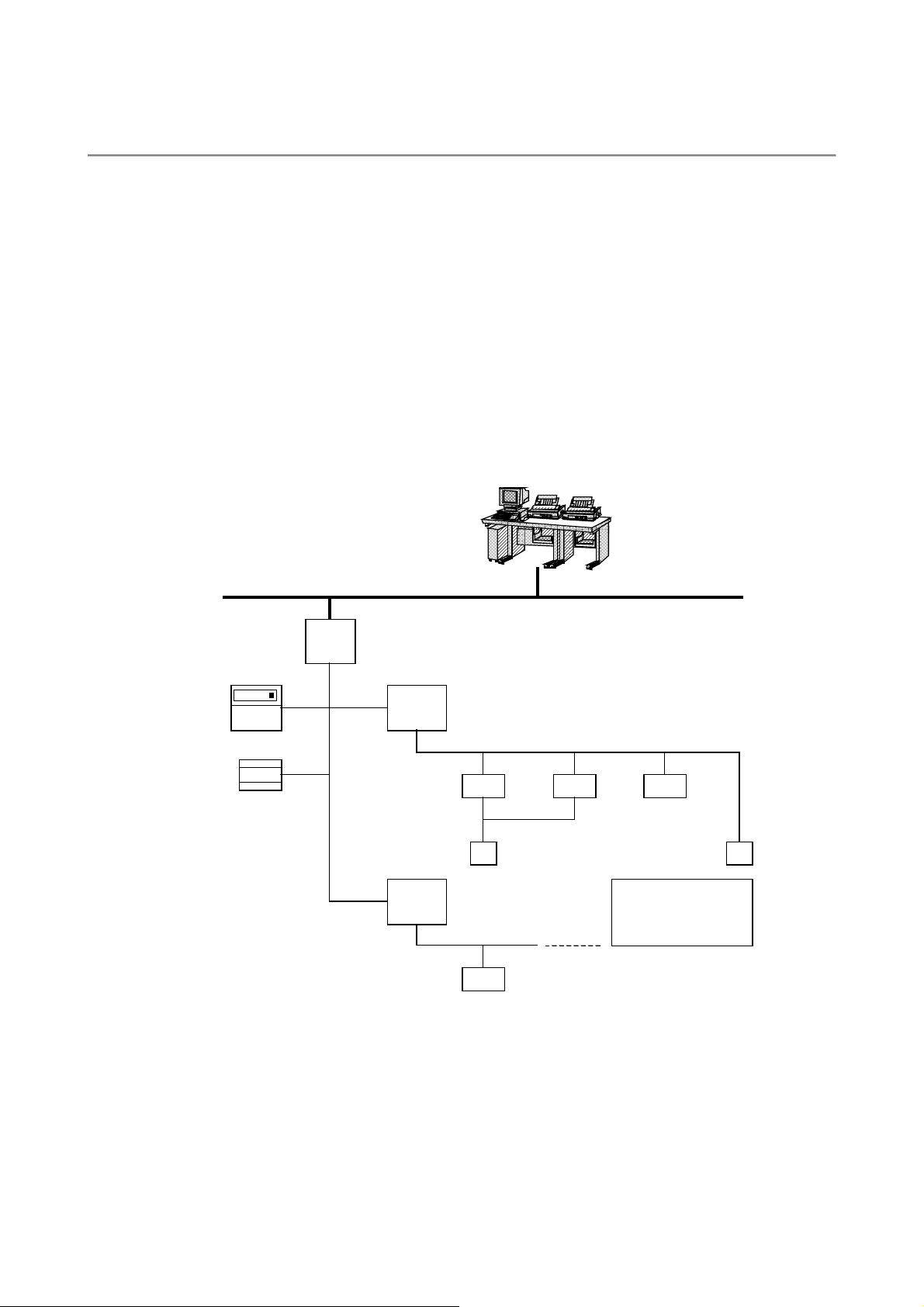
2.1 Outline and features
The LM ADAPTER is a communication interface to connect the Mitsubishi Electric made products for M-NET
use with the LONWORKS network. Only one LM ADAPTER can control and monitor indoor units up to 50
sets.
Since the LONWORKS network is an open protocol, connection with the Building management system
(BMS) and other products usable with LONWORKS can be performed easily thus allowing construction of
various systems including "Schedule operation," "Interlocked operation" and "Energy saving control".
<Features>
- Maximum 50 sets indoor units connectable with one LM ADAPTER
- Operation/monitoring with local remote controllers
- Standard Network Variables Type (SNVT) and enriched function (network variables)
- Various Configuration Properties (CP) essential for network construction
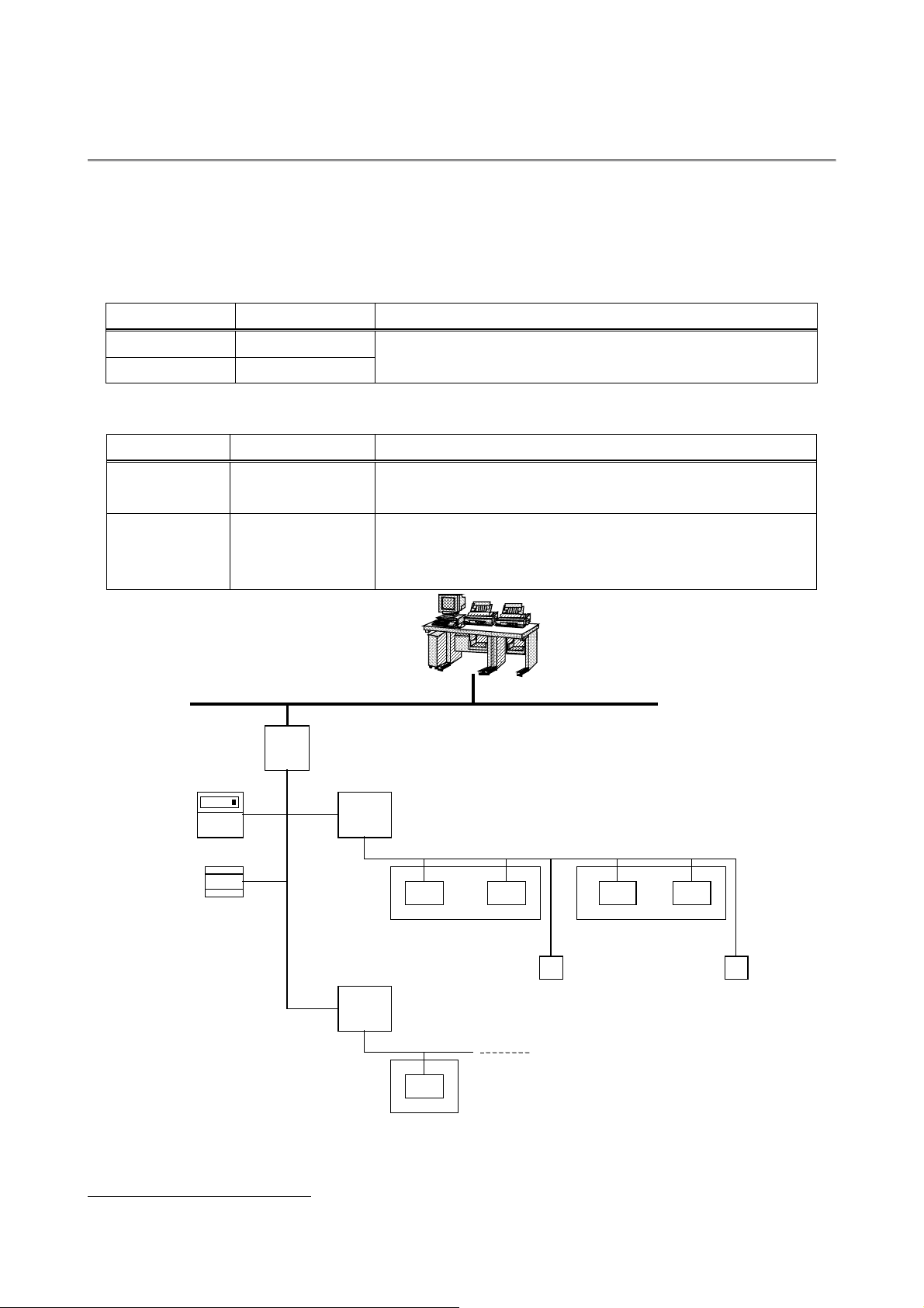
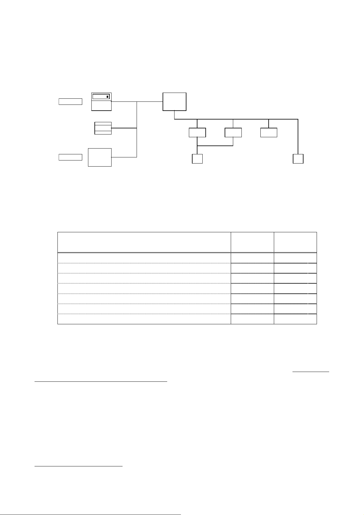
Building management
system (BMS)
LONWORKS network
System remote
controller
Power supply unit
LMAP
OC
M-NET centralized control
transmission line
OC
M-NET indoor-outdoor
tr a ns miss io n line
IC IC IC
MA
OC:Outdoor unit
IC :Indoor unit
MA :MA remo te c o ntr olle r
ME: ME re mote c ont r olle r
IC
*Make s ure to in s t all the lo c a l r e mote
c ont rolle r or sy s t em c ont rolle r .
ME
Figure 1-1. System configuration diagram (Example)
2.2 List of products
The air conditioners controllable with LM ADAPTER are shown below.
Model name Objective models for control
LMAP02 - E CITY MULTI, LOSSNAY, Mr. SLIM
LMAP03 CITY MULTI, LOSSNAY, Mr. SLIM
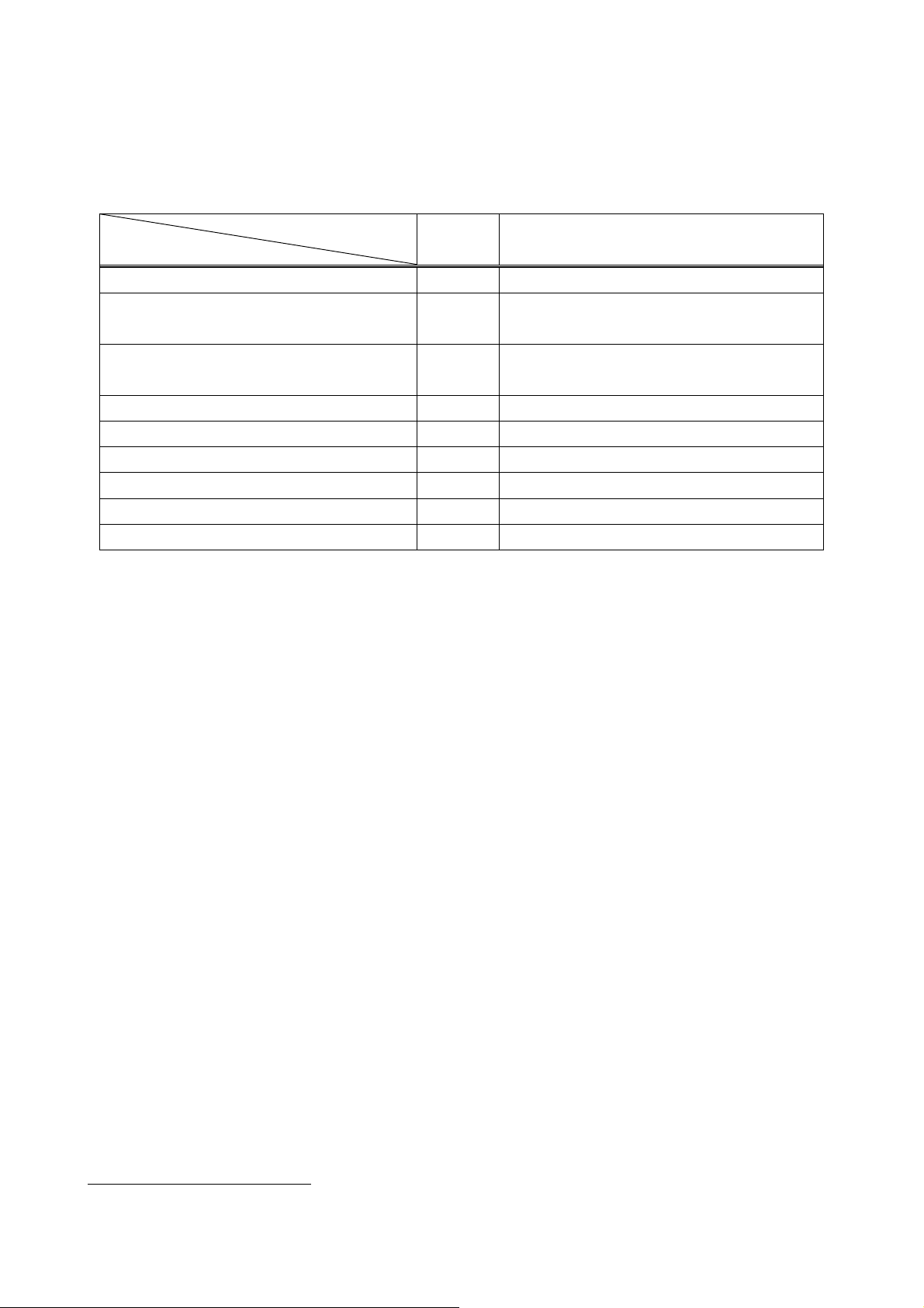
2.3 Function
The basic functions of LM ADAPTER are outlined as below.
1
Details
Items
Emergency stop Stopping all air conditioners. Not prohibiting local remote controller operation.
ON/OFF Operating/monitoring ON/OFF state.
Mode Operating/monitoring the operation mode set for air conditioners & LOSSNAYs.
SetPoint Operating/monitoring the temperature set of air conditioners.
Fanspeed Operating/monitoring the fan airflow rate setting.
Local remote controller prohibit
Forced thermostat OFF Operating/monitoring the forced thermostat OFF of air conditioners.
Filter sign/Run time for filter Resetting/monitoring the integrated data of filter operation time.
Local remote controller setting
Defrosting state Outputting the defrosting status of all air conditioners.
Failure/alarm Outputting the failure of air conditioners, control panels and humidifiers.
LM ADAPTER
abnormal communication state
Air conditioner (charging) information
(thermostat status)
Air conditioner (charging) information
(capacity code)
Space temperature status Outputting the outlet and inlet temperature of each air conditioner.
Operating/monitoring the operation prohibit of local remote controllers.
(ON/OFF, operation mode, temperature setting, batch)
Setting the local remote controller.
(Time, temperature setting range, simplified locking, actual operation mode display, room
temperature display)
Outputting the communication error if existed between LM ADAPTER and air conditioners.
Outputting each state of the operation/thermostat/auxiliary heater of air conditioners.
Outputting the capacity code of air conditioners.
1
The applicable function differs depending on the objective models for control.
2.4 Specification
(1) Product specification
Dimension 340mm(Height) x 360mm(Width) x 59.6mm(Depth)
Weight 3.4 kg
Power source ~220 - 240V (50/60Hz)
Power consumption 10 W
Data holding Memorizing binding information, address information on air conditioners
Environmental
condition
Installation method Mountable in horizontal or vertical direction
External finish Galvanized steel plate
Alias 100 pieces
Explicit message Not applicable yet
Neuron ID Indicated on the seal attached to circuit board (differs by product)
Program ID Indicated on the seal attached to circuit board (differs by product)
Neuron chip
Network transceiver FTT-10A (Free topology 78kbps) 1 piece
Items 1 Specification
and set values in nonvolatile memory. Input/output variables are not
held.
Temperature
Humidity 30 to 95 %RH (No condensation allowed)
Operating
Non operating
- 15 to 43 ℃
- 20 to 60℃
For vertical installation, locate in the direction of the pasted seal.
TMPN3150(10MHz) 1 piece
(2) Performance
Mean communication capacity 2.5 input / second
Peak communication capacity 50 input / second (for 1 second)
Response capacity for poll demand 15 demand / second
Items 2 3 Specification
1
For the detail specification of the LONWORKS network, see the data published by Echelon. "FTT-10A Free Topol ogy Transceiver User's Guide"
2
Transmi tting with an interval time exceeding the capacity hinders normal receiving. Please take a sufficient interval.
3
The Ack Service is recommended for your network service.

(3) External dimension
3. System Design Flow
The following indicates design flow to construct the system of the LONWORKS network by LM ADAPTER.
Step 1: Selecting the air conditioners (objective equipment for control, restrictions, etc.).
Step 2: Selecting the function.
Step 3: Selecting the system control parts
(Quantity of LM ADAPTER, other system controllers, etc.).
Step 4: Determining the air conditioner addresses.
Step 5: Constructing the LONWORKS system.
4. Designing the LMAP02-E / LMAP03
pply
This section summarizes the air conditioners controllable with LM ADAPTER and various restrictions to be
applied. For the details of air conditioning equipment, please refer to the manual of each air conditioner.
4.1 Selecting the air conditioners
4.1.1 Controllable quantity
Models Limitation Detail
LMAP02-E 50 sets
LMAP03 50 sets
4.1.2 Range of group control
Models Limitation Detail
LMAP02-E No group control
function provided
LMAP03 Master SC
LONWORKS network
LMAP
One LM ADAPTER can control indoor units up to 50 sets. The number of
LOSSNAY (including ventilation units) is to be included in this figure.
LM ADAPTER has no group control function.
1
When using other SC in combination, the control can be performed within the
group range set by the SC.
When not using other SC in combination, group control cannot be performed.
BMS
System remote
controller
Power su
1
Abbreviation of system controller
unit
transmis sion line
OC
M-NET c entralize c ontrol
OC
M-NET indoor-outdoor
transmis sion line
IC IC IC
Group1 Group2
ME
IC
*Make sure to inst all a loca l re mote
Group3
controller or sys tem controller.
Figure 4-1. System configuration (Example)
IC
ME
4.1.3 Objective equipment for control
The following table lists the objective air conditioners for control.
Some indoor units own the plural M-NET addresses. For counting the connected numbers, refer to the table
below.
O : Controllable x : Uncontrollable △ : Controllable depending on connected models
Function
Models
LMAP02-E
Counting method of connected quantity
LMAP03
CITY MULTI
Mr. SLIM (1:1, Simultaneous twin/triple/four) 1
Mr. SLIM (Power inverter) 1
Mr. SLIM (Individual twin)
PAC for general purpose/industrial application
LOSSNAY
OA processing unit
Ventilation unit (LOSSNAY adapter connection)
K-control unit 2
○
○
○
× -
×
○
○
△
× -
Quantity of indoor unit
Quantity of outdoor unit
(not including indoor unit quantity)
Quantity of outdoor unit
(not including indoor unit quantity)
Quantity of LOSSNAY
Quantity of LOSSNAY
Quantity of ventilation unit
4.1.4 Connecting location
Connect LM ADAPTER to the centralized system transmission line of air conditioners.
4.1.5 Restriction on M-NET transmission wiring
As the M-NET transmission line has restrictions on its wiring length, wire materials, etc. in accordance with
the system configuration, the design should be conducted taking the transmission lines of air conditioners and
control equipment into your consideration. For detail, please refer to the manuals such as the "DATA BOOK"
of each air conditioner.
1
Require to mount the adapter for M-NET connection (PAC-SF48/49/87MA, PAC-SG40MA)
2
Unable to control/monitor even by connecting the K-transmission converter.
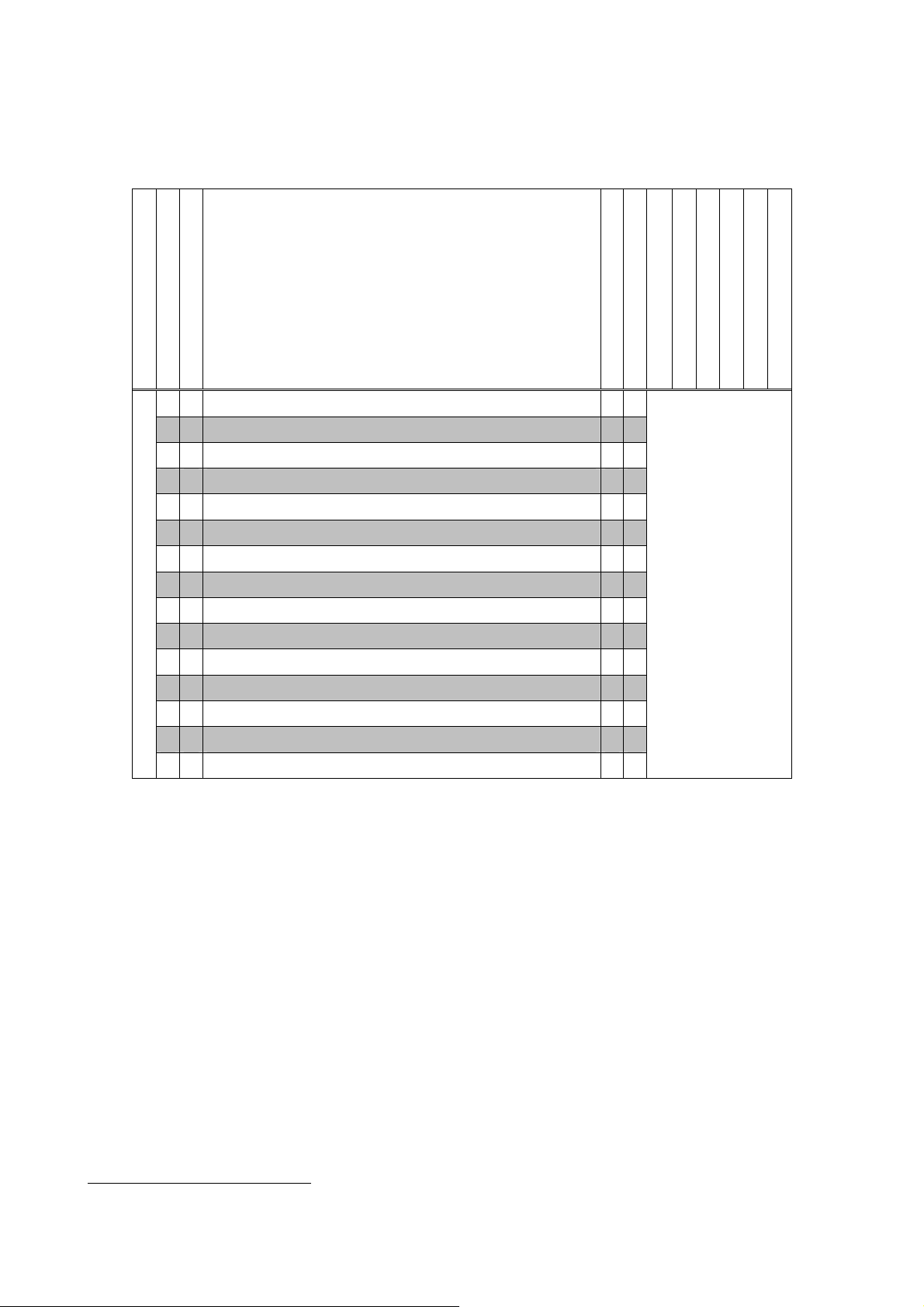
4.2 Selecting the function
The list below shows the operation/monitor function of LM ADAPTER.
(1) Operation/Setting
◎: With function ●: Individual -: Without function
LMAP02-E
Operation/Setting
LMAP03
Request All OFF (Emergency stop)
◎ ◎
Request On/Off
◎ ◎
Request Mode
◎ ◎
SetPoint
◎ ◎
Request LOSSNAY Mode
◎ ◎
Request Fanspeed
◎ ◎
Request Local Prohibit On/Off
◎ ◎
Request Local Prohibit Mode 1
◎ ◎
Request Local Prohibit SetPoint
◎ ◎
Request Collective Operation Prohibit 1
- ◎
Request Forced Thermostat OFF
- ◎
Filter Sign Reset
- ◎
2
Time Stamp
- ◎
Request Limit Temperature Setting Range 2
- ◎
Request Simplified Locking
- ◎
Function
1
2
1
CITY MULTI
● ●
● ●
● ●
● ●
- -
● ●
● ●
● ●
● ●
● ●
● ●
● ●
● -
● -
● -
Mr. SLIM
LOSSNAY (Individual)
Differs by models
LOSSNAY (Interlocked)
OA processing unit (Individual)
OA processing unit (Interlocked)
Ventilation unit (Individual)
Ventilation unit (Interlocked)
1
Applicable only at using of MA remote control ler (PAR-20MAA) for a local remote controller.
2
Applicable only at using of ME remote controller (PAR-F27MEA) for a local remote controller.
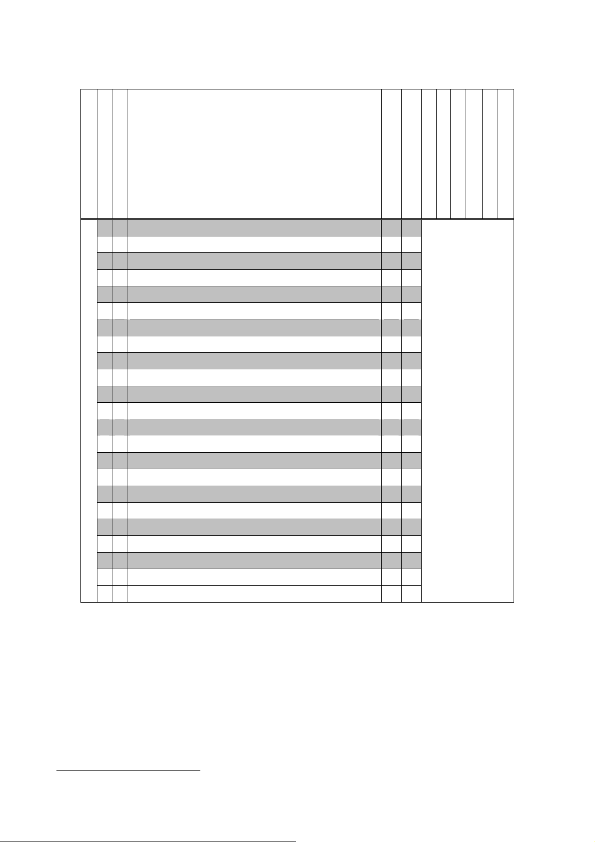
(2) Monitoring/Measuring
LMAP02-E
LMAP03
Emergency state
- ◎
On/Off run state
◎ ◎
Collective On/Off state
- ◎
Mode state
◎ ◎
SetPoint state
◎ ◎
LOSSNAY Mode state
◎ ◎
Fanspeed state
◎ ◎
Local Prohibit On/Off state
◎ ◎
Local Prohibit Mode state 1
◎ ◎
Measuring/Monitoring
◎ ◎
- ◎
- ◎
- ◎
◎ ◎
◎ ◎
- ◎
- ◎
- ◎
- ◎
◎ ◎
- ◎
- ◎
- ◎
Local Prohibit SetPoint state
Collective Local Prohibit state 1
Forced Thermostat OFF state
Filter Run Time
Space Temperature
Alarm state
Collective Alarm for Indoor Unit
Collective Alarm for LM Adapter
Error Code
Error Unit Address
Thermostat On/Off state_1
Thermostat On/Off state_2
Model Code
Defrost state
Function
1
1
◎: With function ●: Individual -: Without function
CITY MULTI
Mr. SLIM
LOSSNAY (Individual)
LOSSNAY (Interlocked)
OA processing unit (Individual)
OA processing unit (Interlocked)
Ventilation unit (Individual)
Ventilation unit (Interlocked)
● ●
● ●
● ●
● ●
● ●
- -
● ●
● ●
● ●
● ●
● ●
● ●
● ●
● ●
● ●
● ●
● ●
● ●
● ●
● ●
● ●
● ●
● ●
Differs by models
1
Applicable only at using of MA remote control ler (PAR-20MAA) for a local remote controller.
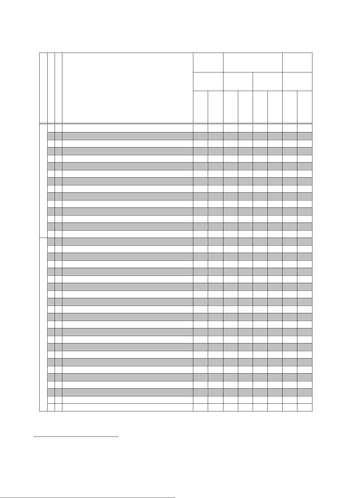
(3) List of LOSSNAY function by models
◎ ◎
●●●●● ● ●
●
LMAP02-E
LMAP03
Function
Request All OFF (Emergency stop)
Request On/Off
◎ ◎
Request Mode
◎ ◎
SetPoint
◎ ◎
Request LOSSNAY Mode
◎ ◎
Operation/Setting
Measuring/Monitoring
Request Fanspeed
◎ ◎
Request Local Prohibit On/Off
◎ ◎
Request Local Prohibit Mode
◎ ◎
Request Local Prohibit SetPoint
◎ ◎
Request Collective Operation Prohibit
- ◎
Request Forced Thermostat OFF
- ◎
Filter Sign Reset
- ◎
Time Stamp
- ◎
Request Limit Temperature Setting Range
- ◎
Request Simplified Locking
- ◎
Emergency state
- ◎
On/Off run state
◎ ◎
Collective On/Off state
- ◎
Mode state
◎ ◎
SetPoint state
◎ ◎
LOSSNAY Mode state
◎ ◎
Fanspeed state
◎ ◎
Local Prohibit On/Off state
◎ ◎
Local Prohibit Mode state
◎ ◎
Local Prohibit SetPoint state
◎ ◎
Collective Local Prohibit state
- ◎
Forced Thermostat OFF state
- ◎
Filter Run Time
- ◎
Space Temperature
◎ ◎
Alarm state
◎ ◎
Collective Alarm for Indoor Unit
◎ ◎
Collective Alarm for LM ADAPTER
- ◎
Error Code
- ◎
Error Unit Address
- ◎
Thermostat On/Off state_1
◎ ◎
Thermostat On/Off state_2
- ◎
Model Code
- ◎
Defrost state
- ◎
5
4
4
4
4
4
5
4
4
◎: With function ●: Applicable ▲:Partially applicable -: Not applicable
Ventilation
LOSSNAY OA processing unit
unit
LGH -RX3-E GUF -RD(H) GUF-RD(H)2 [Adapter]
PZ-53ADF-E
Interlocked
Individual
Interlocked
Individual
Interlocked
Individual
Individual
● ●1● ●1 ● ●1 ● ●
- - ● ●2 ● ●2 - -
- - ● ▲3 ● ▲3 - -
● - - - - - ● -
● - ● - ● - ▲ -
● - - - ● - - -
- - - - ● - - -
4
- - - - ● - - -
● - - - ● - - -
- - ● - ● - - -
● - ● - ● - ● -
5
- - - - - - - -
- - - - - - - -
-
- - - - - - -
● ● ● ● ● ● ● ●
● ●1● ●1 ● ●1 ● ●
● ●1 ● ●1 ● ●1 ● ●
- - ● - ● - - -
- - ● - ● - - -
● - - - - - ● -
● - ● - ● - ▲ -
● - - - ● - - -
- - - - ● - - -
- - - - ● - - -
● - - - ● - - -
- - ● - ● - - -
● - ● - ● - ● -
- - ● - ● - - -
● ● ● - ● - - -
● ● ● - ● - ● ●
● ● ● - ● - ● ●
● ● ● - ● - - -
● ● ● - ● - - -
- - ● - ● - - -
- - ● - ● - - -
- - ● - ● - - -
- - - - - - - -
Interlocked
1
1
1
1
Provides ON/OFF operation interlocked with indoor unit.
2
Provides same operation mode with that of indoor unit.
3
Provides same target (set) temperature with that of indoor unit. But effective only under cooling mode for OA processing unit.
4
Applicable only at using of MA remote control ler (PAR-20MAA) for local remote controller.
5
Applicable only at using of LOSSNAY remote controller (PZ-52SF-E) for the local remote controller.

4.3 Selecting the system control parts
g
g
g
g
Using the system controller (SC) together other than LM ADAPTER allows connecting operation. Some
rules to be observed for this purpose are introduced below.
4.3.1 Master controller and slave controller
When LM ADAPTER is used together with other system controller inside a system under own control, it is
essential to set a slave SC (requiring a DIP-SW change). In this case, set it so that the control range of LM
ADAPTER is included within the control range of the system controller (air conditioner) which is to be the
master SC.
M-NET centralized
Mas t er S C
Sys tem remote
c ont rolle r
c ont rol t r ansmis s io n line
OC
M-NET indoor-outdoor
transmission line
IC IC IC
MA
ME
Slave SC
Power supplyunit
LMAP
Figure 4-2. System configuration of system controller
(1) In the case when the control range of the LM ADAPTER is covering that of plural system controllers, make
sure to install the Master system controller that covers the LM ADAPTER control range.
Master SC
SC1
control
e
ran
LM ADAPTER
control range
SC2
control
e
ran
SC1
control
ran
LM ADAPTER
control range
e
SC2
control
e
ran
(2) In the case when the LM ADAPTER control range is covering the control range of the system controller
partially, install the system controller so that it covers the entire control range of LM ADAPTER.
SC2
control range
SC1
control range
LM ADAPTER
control range
SC1
control range
LM ADAPTER
control range
4.3.2 Local remote controller
The local remote controller includes ME remote controller (PAR-F27MEA, etc.) to be connected to the
M-NET indoor-outdoor transmission line of air conditioners and MA remote controller (PAR-20MAA, etc.) to be
connected to each indoor unit. Each remote controller provides a different function usable by LM ADAPTER
and a different system construction method.
M-NET centralized
Mas t er S C
c ont r ol t rans mis sion lin e
System remote
contoller
OC
M-NET indoor-outdoor
transmission line
IC IC IC
MA
ME
Slave SC
Power supply unit
LMAP
Figure 4-3. System configuration of local remote controller
(1) Comparison of function by local remote controllers
The usable function (network variables) by LM ADAPTER differs depending on the model of the local remote
controllers (MA remote controller/ME remote controller).
Function (NV names)
Request Local Prohibit (ON/OFF , Mode , SetPoint)
Local Prohibit State (ON/OFF , Mode , SetPoint)
Request Collective Local Prohibit
Collective Local Prohibit State
Time Stamp
Request Limit Temperature Setting Range
Request Simplified Locking
MA remote
controller
○ △
○ △
○ △
○ △
× △
× △
× △
ME remote
controller
1
1
1
1
2
2
2
○ : With function △ : Possible with limitation ×: Without function
(2) Caution on a system without using remote controller
The following problems will be incurred when the operation/monitoring is done only from the BMS
(centralized monitoring system) without using the local remote controller. Therefore, please install a local
remote controller or system controller without fail.
① Test run can not be applied to air conditioners until the BMS has started up.
② Air conditioners can not be operated or monitored when trouble is generated on the BMS and
LM ADAPTER.
③ The detail of the trouble i.e. during the stopping of indoor units can not be clarified.
④ The operation/setting of the items other than that controlled by the BMS cannot be performed.
⑤ Interlocked setting of LOSSNAY and air conditioners can not be performed.
1
Applicable to some model of CITY MULTI air conditioners ( manufactured after January 2003 ) even when using ME remote controller.
2
Applicable when only using ME remote controller for the standard models except the medium temperature models.
4.3.3 External contact input/output
g
y
The external contact input/output function is not provided to LM ADAPTER.
4.3.4 Power supply to M-NET transmission line
The M-NET centralized system controller line should be powered. For the system using other system
controller or that with LOSSNAY only, the power supply unit for transmission line is required. In accordance
with the system configuration, the setting of LM ADAPTER and outdoor units should partially be changed.
Please conduct the setting operation by referring to the "Installation Manual" of LM ADAPTER. For the power
supply capacity of the power supply unit and the selection of the unit, please refer to the manuals (like DATA
BOOK) of each air conditioner.
Installation of power supply unit
Model name
Individual With SC
1
LMAP02-E
LMAP03
Not required Required PAC-SC34KUA
4.4 Object
4.4.1 Network variables and objects
The network variables provided allows the LA ADAPTER to operate/monitor plural equipment (indoor unit,
LOSSNAY, etc.) The functional profile (object) represents the network variables collected for each objective
equipment to be controlled. Here the objects and network variables are outlined, and the relationship with air
conditioners is explained. For the detail of each object and the specification of the network variables, please
refer to the "Network Variables Specification" of each product.
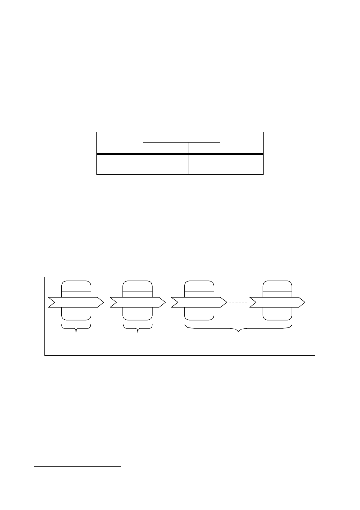
(1) Object configuration of LM ADAPTER
Node
Object
Indoor [0]
Indoor [1]
Indoor [50]
For node
object
For collective variables
and confi
urationpropert
For indoor unit
1
Restriction will be applied depending on the quantity of system controllers or local remote controllers. For detail, please refer to the DATA BOOK and the other manual.
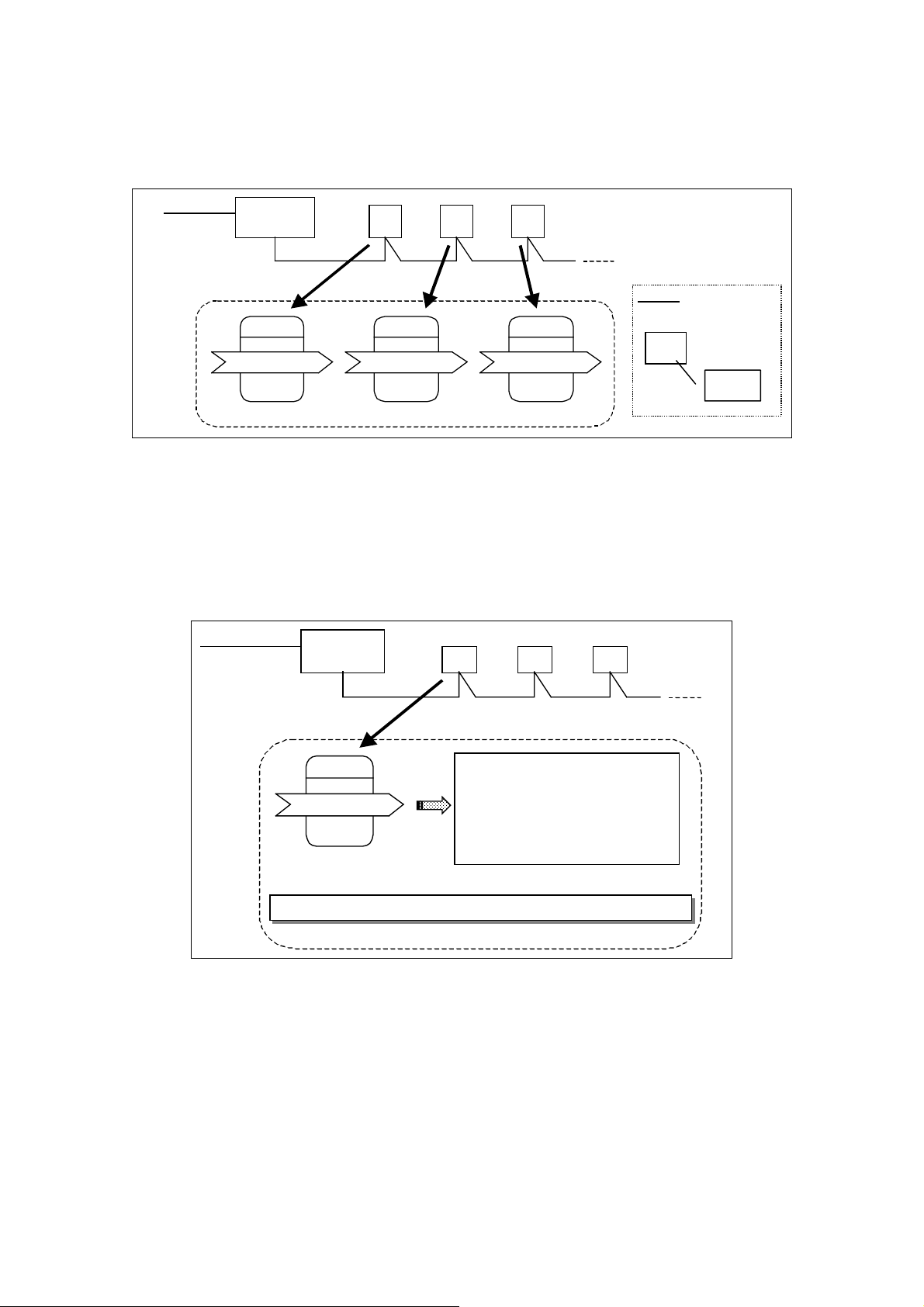
(2) Object and equipment address
T
T
f
The object for indoor units is individually related with the objective equipment for control. The object (Indoor
[1] ~ Indoor [50]) corresponds to the indoor unit (LOSSNAY, ventilation unit, Mr. SLIM) with the M-NET
address of 01 ~ 50 being set to each equipment.
Outdoor unit
M-NET centralized
control transmission line
051
Indoor [1]
IC
001
Indoor [2]
Object of LM ADAPTER
IC
002
IC
003
M-NETIndoor-outdoor
transmission line
Indoor [3]
Legend
IC
05
OC:Outdoor unit
IC:Indoor unit
M-NET
address
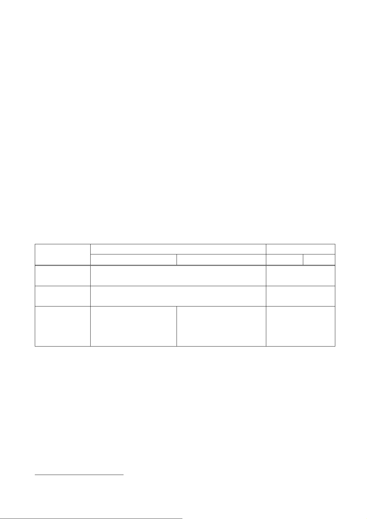
4.4.2 Network variables and air conditioner address
LM ADAPTER owns the network variables for each air conditioner. The network variables include
set/monitor of an air conditioner individually and to set/monitor of all air conditioners collectively.
Please set so that the M-NET address of the objective air conditioner for control will agree to the name of the
variable.
centralized
M-NE
control transmission line
Outdoor unit
051
IC
001
IC
002
M-NE
transmission line
IC
003
Indoor-outdoor
Indoor [1]
For No.1 indoor unit
Network variable name→Function name + M-NETaddress (3-digit display)
Relationship between M-NET address and Network variables
Request On/Of
On/Off run state
SetPoint :nviSetP_001
SetPoint state
:
:
:
:
nviOnOff_001
:
nvoOnOff_001
:
nvoSetP_001
:
:
:
4.5 Restrictions on system configuration
The restrictions in constructing the system by LM ADAPTER are outlined here.
4.5.1 Restrictions by objective models for control
(1) Control of LOSSNAY (including OA processing unit and ventilation unit with LOSSNAY adapter)
①LOSSNAY can be operated interlocking with air conditioners on M-NET. As the interlock setting cannot be
executed with LM ADAPTER, set it with other system controller or local remote controller (ME remote
controller: PAR-F27MEA). In this case, the setting of the function setting SW (DIP- SW1-5) on
LM ADAPTER should be changed.
②As the controllable function differs, please configure a system so that the individual operation of
LOSSNAY and the equipment interlocked (with air conditioner) are not mixed within the control range of
LM ADAPTER.
③If the individual operation and interlocked operation of LOSSNAY is desired to switch over depending on
the seasons, set LOSSNAY for individual operation, while set it to be operated interlocking with the air
conditioner at the BMS side also.
4.5.2 Restrictions by system configuration
(1) Group control
In the case when the group setting of indoor units are carried out by the local remote controller or system
controller, the operation from the BMS is performed as follows.
Operation Monitoring Group setting
LMAP02-E LMAP03 LMAP02-E LMAP03
No setting
(individual)
Setting by the local
remote controller
Setting by the system
controller
Required to issue a same command to all indoor units
every unit
Required to issue a same command
to all indoor units
every unit every unit
every unit
every unit
Principal 1 unit in the same group
When using “Forced Thermostat
every unit
OFF” is required to request into
indoor units individual
4.5.3 Restrictions by control items
(1) Operation prohibit
①When using together the system controller that can set to prohibit the local remote controller operation,
make the controller for setting of operation prohibit one unit, either LM ADAPTER (BMS) or the system
controller.
②Operation prohibit can not be applied to other system controllers by LM ADAPTER (from BMS)
③Although air conditioners can not be operated by the local remote controller of which operation is being prohibited,
they can be operated by LM ADAPTER (BMS) or other system controllers.
1
At the unit of lowest address in the same group

(2) Emergency stop
The emergency stopping of LM ADAPTER stops all air conditioners together, however it does not set the
operation prohibit of the local remote controller allowing the operation from other system controller or local
remote controller. To prohibit operation from the local remote controller, therefore, set it by entering
[Request Collective Local Prohibit] (collective).
*Operating to run during emergency stopping only results in immediate stopping.
(3) Operation mode
In the case of cooling/heating selectable models of CITY MULTI, the operation mode will be determined by
the principle of the "Priority for former pressing." Under the circumstance, a same command should be
issued to all indoor units within a same refrigerant system to change the operation mode.
Indoor unit 1
Indoor unit 2
Outdoor unit
Coo l
Coo l
Coo l
Heat (Inoperable)
Cool ( Inoperable)
Hea t
Hea t
5. Design and Operation of LONWORKS System
This section introduces the mechanism, function and operating method of LM ADAPTER in configuring the
system of LONWORKS network by LM ADAPTER. As the operating method shown here represents just one
of the examples, you are kindly requested to carry out your designing to meet the system configuration or
operation in the actual system.
5-1 Constructing the LONWORKS network
The flow of installation procedure for LONWORKS network is shown below.
Step 1: Addressing (to determine the address of each node)
Step 2: Binding (to connect network variables)
Step 3: Configuration (for optimum service of each connection, adjustment of
re-transmission frequency and interval)
(1) Addressing
An address is assigned to each node (equipment applicable to LONWORKS) on the LONWORKS network.
Set this address by using the install tool. Setting by using LM ADAPTER is not necessary.
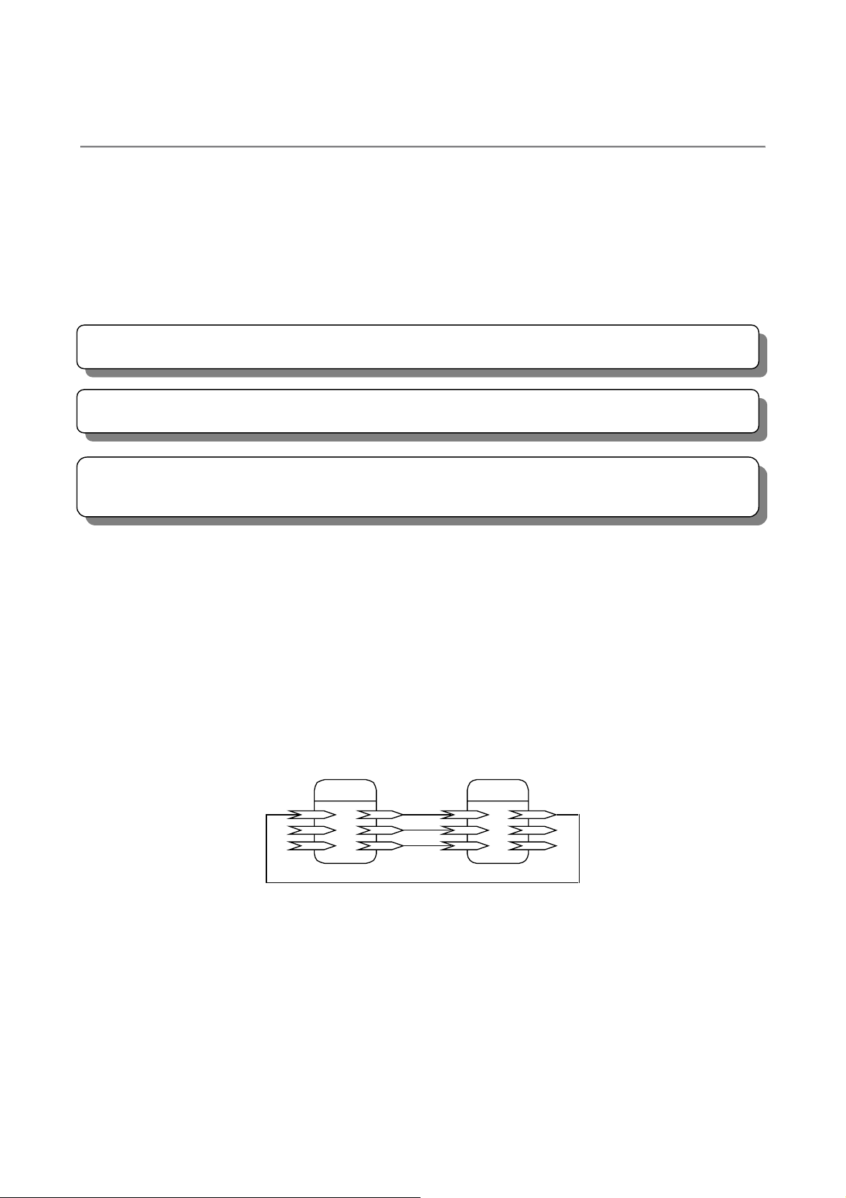
(2) Binding
The network variables between each node should be related with the exclusive tool like LonMaker for
Windows ® or the like.
(3) Configuration
For the configuration property of LM ADAPTER, the initial value was set at factory shipment. The set value
may be changed depending on the configuration or operation of the network.
=
BMS Indoor [1]
Binding of network variables
=

5.2 Function relating to installing
(1) Service pin (Service switch)
The service pin is used at the installation of LONW ORKS network.
Pressing the service pin sends out the service pin-message (control message including Neuron ID and
Program ID) to the network.
(2) Service LED
The service ID indicates the present state of the product.
In the case of LM ADAPTER under the shipment state (Non-configured state), the service LED is blinking.
(3) WINK
Upon receipt of the WINK message from the LONWORKS network, LM ADAPTER blinks the maintenance
LED 001 for about 10 seconds.
(4) Commission
After completing the binding, the set detail is reflected on the node. Doing this way allows communication
between the nodes on the LONWORKS network.
(5) XIF
To design the LONWORKS network, the configuration information of each node, interface (network
variables), etc. are required. When the product is already in your hand, such information can be obtained from
the LONWORKS network. Without the product, however, you may get it from XIF (eXternal Interface File)
locating the interface information of the product.
 Loading...