

Page 1
Page 2

Page 3
SAFETY PRECAUTIONS
(Always read these instructions before using this equipment.)
Before using this product, please read this manual and the relevant manuals introduced in this manual
carefully and pay full attention to safety to handle the product correctly.
The instructions given in this manual are concerned with MELSEC communication protocol. For the safety
instructions of the programmable controller system, please read the user's manual for the CPU module to
use.
!
In this manual, the safety instructions are ranked as "
!
WARNING
!
CAUTION
!
Note that the
Always follow the instructions of both levels because they are important to personal safety.
Please save this manual to make it accessible when required and always forward it to the end user.
CAUTION level may lead to a serious consequence according to the circumstances.
Indicates that incorrect handling may cause hazardous conditions,
resulting in death or severe injury.
Indicates that incorrect handling may cause hazardous conditions,
resulting in minor or moderate injury or property damage.
[Design Precautions]
WARNING" and "!CAUTION".
!
WARNING
When changing data of the running programmable controller from a peripheral connected to the
CPU module or from a personal computer connected to an intelligent function module, configure
an interlock circuit in the sequence program to ensure that the entire system will always operate
safely.
For program modification and operating status change, read relevant manuals carefully and
ensure the safety before operation.
Especially, when a remote programmable controller is controlled by an external device,
immediate action cannot be taken if a problem occurs in the programmable controller due to a
communication failure.
To prevent this, configure an interlock circuit in the sequence program, and determine corrective
actions to be taken between the external device and CPU module in case of a communication
failure.
Do not write any data to the "system area" of the buffer memory in the intelligent function
module.
Also, do not use any "use prohibited" signals as an output signal from the programmable
controller CPU to the intelligent function module.
Doing so may cause malfunction of the programmable controller system.
A - 1 A - 1
Page 4

[Operation Precautions]
!
CAUTION
When changing data and operating status, and modifying program of the running programmable
controller from a personal computer connected to an intelligent function module, read relevant
manuals carefully and ensure the safety before operation.
Incorrect change or modification may cause system malfunction, damage to the machines, or
accidents.
While set values in the buffer memory are being registered to the flash ROM in the module, do
not turn off the power to the module and do not reset the CPU module.
Doing so will affect the flash ROM data, and setting to the buffer memory and registration to the
flash ROM need to be performed again.
Also, it may cause failure or malfunction of the module.
A - 2 A - 2
Page 5

CONDITIONS OF USE FOR THE PRODUCT
(1) Mitsubishi programmable controller ("the PRODUCT") shall be used in conditions;
i) where any problem, fault or failure occurring in the PRODUCT, if any, shall not lead to any major or
serious accident; and
ii) where the backup and fail-safe function are systematically or automatically provided outside of the
PRODUCT for the case of any problem, fault or failure occurring in the PRODUCT.
(2) The PRODUCT has been designed and manufactured for the purpose of being used in general
industries.
MITSUBISHI SHALL HAVE NO RESPONSIBILITY OR LIABILITY (INCLUDING, BUT NOT LIMITED
TO ANY AND ALL RESPONSIBILITY OR LIABILITY BASED ON CONTRACT, WARRANTY, TORT,
PRODUCT LIABILITY) FOR ANY INJURY OR DEATH TO PERSONS OR LOSS OR DAMAGE TO
PROPERTY CAUSED BY the PRODUCT THAT ARE OPERATED OR USED IN APPLICATION NOT
INTENDED OR EXCLUDED BY INSTRUCTIONS, PRECAUTIONS, OR WARNING CONTAINED IN
MITSUBISHI'S USER, INSTRUCTION AND/OR SAFETY MANUALS, TECHNICAL BULLETINS AND
GUIDELINES FOR the PRODUCT.
("Prohibited Application")
Prohibited Applications include, but not limited to, the use of the PRODUCT in;
Nuclear Power Plants and any other power plants operated by Power companies, and/or any other
cases in which the public could be affected if any problem or fault occurs in the PRODUCT.
Railway companies or Public service purposes, and/or any other cases in which establishment of a
special quality assurance system is required by the Purchaser or End User.
Aircraft or Aerospace, Medical applications, Train equipment, transport equipment such as Elevator
and Escalator, Incineration and Fuel devices, Vehicles, Manned transportation, Equipment for
Recreation and Amusement, and Safety devices, handling of Nuclear or Hazardous Materials or
Chemicals, Mining and Drilling, and/or other applications where there is a significant risk of injury to
the public or property.
Notwithstanding the above, restrictions Mitsubishi may in its sole discretion, authorize use of the
PRODUCT in one or more of the Prohibited Applications, provided that the usage of the PRODUCT is
limited only for the specific applications agreed to by Mitsubishi and provided further that no special
quality assurance or fail-safe, redundant or other safety features which exceed the general
specifications of the PRODUCTs are required. For details, please contact the Mitsubishi
representative in your region.
A - 3 A - 3
Page 6
REVISIONS
The manual number is given on the bottom left of the back cover.
Print Date Manual Number Revision
Dec., 1999 SH(NA)-080008-A First edition
Oct., 2000 SH(NA)-080008-B Reflect the contents of the function version B.
Put Windows base software products together from Mitsubishi
Programmable Controller MELSEC series to Mitsubishi integrated FA
software MELSOFT series. Standardize the name from software package
(GPP function) to product name (GX Developer).
Correction
Contents, Entire manual (change MELSECNET/10H to
MELSECNET/H), About Manuals, About the Generic Terms and
Abbreviations, Section 1.1(5), Section 2.2, 2.4, 2.6, 2.7 (g), 2.9, 2.10,
Section 3.1.1, 3.1.2 (figure), 3.1.3, 3.1.4 (figure), 3.1.5 (figure), 3.1.6
(5), REMARKS, 3.2 (table), 3.3.1 (table 6.3), 3.3.8 (POINT (screen)),
3.8.1 (2)(a), 3.8.2 (4), 3.8.5, 3.8.6, Section 4.1 (figure), Section 5.1.1,
5.1.2 (figure), 5.1.3, 5.1.5 (table)*3, 5.2.1 (2) (table), 5.2.8, 5.4.2, 5.4.3,
Section 6.1.1, 6.1.2 (figure), 6.1.3, 6.2*3 (table), 6.3.1 (2) (table), 6.3.8
POINT (3), 6.4.9POINT (3), Appendix 1, 2
Jun., 2001 SH(NA)-080008-C Standardize the name from utility package (QSCU) to product name (GX
Configurator-SC).
Correction
About Manuals, The Manual's Use and Structure, About the Generic
Terms and Abbreviations, Meanings and Descriptions of Terminology,
Section 1.1(5), Section 2.2(table), 2.6.1(1)(table), 2.6.2(table), 2.10(4),
Section 3.2(table), 3.3.1(table), 3.3.2, 3.3.3, 3.3.7, 3.3.8(2)(3),
3.3.9(2)(3)(4), 3.3.10(4), 3.4.3, 3.5, 3.6, 3.8.5(2), 3.8.16, 3.17.2, Section
4.4, Section 5.2.8(2)POINT, 5.5, Section 6.2
3, 6.3.1(2), Appendix 3.1
Addition
Section 2.11
Jan., 2003 SH(NA)-080008-D
Additional model
QJ71C24N,QJ71C24N-R2, QJ71C24N-R4
Correction
The Manual's Use and Structure, About the Generic Terms and
Abbreviations, Section 1.1(5), Section 2.5(3), 2.6.1, 2.8, Section
3.1.2(1)(5), 3.1.3(3), 3.2, 3.3.1, 3.3.10(5)POINT, 3.5.2, 3.6.1POINT,
3.6.7, 3.13, Section 5.1.5, 5.2.1POINT, 6.1.2(1)
Apr., 2003 SH(NA)-080008-E
Additional model
QJ71E71-B5
Deleted model
QJ71E71
Correction
About the Generic Terms and Abbreviations, Section 2.6.1(2), Section
3.5.2, Section 6.1.3(4)
Jun., 2004 SH(NA)-080008-F
Correction
About the Generic Terms and Abbreviations, Section 2.6.1, 2.6.3,
2.10(4)(b), 3.1.3(2)(3), 3.1.6(5), 3.2, 3.3.1(3), 3.5.2(1), 3.6.7, 3.8.1,
3.8.11 POINT, Section 6.1.3(4), 6.3.1(2)
A - 4 A - 4
Page 7
The manual number is given on the bottom left of the back cover.
Print Date Manual Number Revision
Aug., 2005 SH(NA)-080008-G
Correction
About the Generic Terms and Abbreviations, Meanings and
Descriptions of Terminology, Section 2.7, Section 3.3.2 POINT
Addition
Chapter 3 (4E frame)
Jun., 2006 SH(NA)-080008-H
Jul., 2007 SH(NA)-080008-I
Correction
Section 3.2, 3.3.1, 3.3.8, 3.3.9, 3.5.2
Change of a term
"PLC" was changed to "programmable controller".
Correction
About the Generic Terms and Abbreviations, Section 1.2(2), Section
2.2, 2.4, 2.6.1, 2.6.2, 2.6.3, 2.9, 2.10(2)(4), Section 3.1.3(1), 3.1.6(5),
3.2*11, 3.3.1(3), 3.5.2(1), 3.13.1, 3.6.7, Section 5.1.3(4), Section
6.1.3(3), 6.3.1(2), Appendix 3.1
Nov., 2007 SH(NA)-080008-J
Aug., 2008 SH(NA)-080008-K
Correction
Section 1.1(5), 2.1(3), 2.6.1(1), 3.5.2, 5.1.5, 5.2.1(2), 6.2
Correction
About the Generic Terms and Abbreviations, Section 1.1, 1.2, Section
2.1, 2.2, 2.4 to 2.6, 2.8 to 2.11, 3.1.3, 3.1.6, 3.2, 3.3.1 to 3.3.10, 3.5.2,
3.6.7, 3.18, Section 5.1.3, 5.1.5, 5.2.1, Section 6.1.3, 6.2, 6.3.1,
Appendix 1, 1.2, 1.3, 2
Addition
Section 2.12
Feb., 2009 SH(NA)-080008-L
Correction
About the Generic Terms and Abbreviations, Section 2.1(3), 2.6.1,
Section 3.2*12, 3.5.2, 3.6.7, Section 5.1.5*7, 5.2.1, Section 6.2*7,
6.3.1*2
Jan., 2010 SH(NA)-080008-M
Additional model
LJ71C24, LJ71C24-R2
Correction
SAFETY PRECAUTIONS, RELEVANT MANUALS,
MANUAL PAGE ORGANIZATION,
GENERIC TERMS AND ABBREVIATIONS, TERMS, Section 2.6.1,
Section 3.1.6, 3.2, 3.3.1, 3.6.7, 3.8.1, 3.8.6, 3.8.7, 3.8.10, 3.8.12,
3.8.13, 3.8.15, 3.11.1, 3.13.1, Section 5.1.5, Appendix 1.3, 3.1
Addition
CONDITIONS OF USE FOR THE PRODUCT
Apr., 2010 SH(NA)-080008-N
Correction
GENERICTERMS AND ABBREVIATIONS, Section 1.1, 2.2, 2.6, 2.6.3,
2.9 to 2.11, 3.1.3, 3.1.6, 3.2, 3.3.2 to 3.3.10, 3.6.7, 5.1.3, 6.1.3, Appendix
1.3, 2
A - 5 A - 5
Page 8
The manual number is given on the bottom left of the back cover.
Print Date Manual Number Revision
May, 2011 SH(NA)-080008-O
Correction
Section 2.1, 2.2, 2.6.1, 2.7.2, 3.1.3, 3.1.6, 3.2, 3.6.1, 3.7.3, 3.8, 3.8.1,
3.8.2, 3.8.9, 3.8.10, 3.8.11, 3.8.12, 3.8.13, 3.9.2, 3.9.3, 3.14, 4.3, 5.1.3,
5.1.5, Appendix 1.2
Jul., 2011 SH(NA)-080008-P
Oct., 2011 SH(NA)-080008-Q
Correction
Section 1.1, 2.6.1, 2.11, 3.6.7, 5.2.1, 6.3.1
Correction
Section 2.4, 2.6.1, 2.7.2, 2.8, 2.10, 2.12, 3.2, 3.3.1, 3.4.1, 3.11.1,
3.11.2, 3.18, 6.1.3, 6.2, 6.3.1, Appendix 3.1
Feb., 2013 SH(NA)-080008-R
Additional model
LJ71E71-100
Correction
RELEVANT MANUALS, GENERIC TERMS AND ABBREVIATIONS,
TERMS, Section 2.6.1, 2.7.1, 3.2, 3.3.1, 3.6.7, 3.8.1, 3.8.7, 3.8.12,
3.8.13, 3.8.15, 6.2, Appendix 1.2, 3.1
Japanese Manual Version SH-080003-X
This manual confers no industrial property rights or any rights of any other kind, nor does it confer any patent
licenses. Mitsubishi Electric Corporation cannot be held responsible for any problems involving industrial property
rights which may occur as a result of using the contents noted in this manual.
1999 MITSUBISHI ELECTRIC CORPORATION
A - 6 A - 6
Page 9

INTRODUCTION
Thank you for purchasing the MELSEC-Q/L series programmable controller.
This manual describes the functions of the MELSEC-Q/L series programmable controllers.
Before using this product, please read this manual and the relevant manuals carefully and develop familiarity
with the functions and performance of the MELSEC-L series programmable controller to handle the product
correctly.
Please always forward this manual to the end user.
CONTENTS
SAFETY PRECAUTIONS ........................................................................................................................A- 1
CONDITIONS OF USE FOR THE PRODUCT .......................................................................................A- 3
REVISIONS ..............................................................................................................................................A- 4
INTRODUCTION......................................................................................................................................A- 7
RELEVANT MANUALS............................................................................................................................A- 13
MANUAL PAGE ORGANIZATION ..........................................................................................................A- 15
GENERIC TERMS AND ABBREVIATIONS ...........................................................................................A- 17
TERMS .....................................................................................................................................................A- 19
1 OVERVIEW 1- 1 to 1- 4
1.1 Overview of the MELSEC Communication Protocol............................................................................ 1- 1
1.2 Features of the MELSEC Communication Protocol ............................................................................ 1- 3
2 DATA COMMUNICATION USING THE MELSEC COMMUNICATION PROTOCOL 2- 1 to 2- 34
2.1 Types and Applications of Data Communication Frames ...................................................................2- 1
2.2 Accessible Range of Each Data Communication Frames .................................................................. 2- 3
2.3 How to Read the Control Procedures of the MC Protocol................................................................... 2- 5
2.4 Access Timing of the Programmable Controller CPU Side ................................................................. 2- 6
2.5 Setting Method for Writing to the Programmable Controller CPU during RUN .................................. 2- 8
2.6 Accessing Other Stations ..................................................................................................................... 2- 9
2.6.1 Accessible programmable controllers of other stations ................................................................ 2- 9
2.6.2 Example of accessible station when each frame is used .............................................................2- 12
2.6.3 Example of designating data items for accessing other station designated within each data
communication frame .................................................................................................................... 2- 16
2.7 Precautions on Data Communication................................................................................................... 2- 19
2.7.1 When using E71 ............................................................................................................................. 2- 19
2.7.2 When using C24............................................................................................................................. 2- 21
2.8 Time Chart and Communication Time of the Transmission Sequence of
the Serial Communication Module ....................................................................................................... 2- 22
2.9 Transmission Time When Accessing Other Stations via CC-Link IE Controller Network,
CC-Link IE Field Network, MELSECNET/H, MELSECNET/10 ........................................................... 2- 25
2.10 Compatibility with Multiple CPU Systems .......................................................................................... 2- 28
2.11 Compatibility with the Serial Communication Function in the CPU Module ..................................... 2- 32
2.12 Compatibility with Programmable Controller CPU with Built-In Ethernet Port.................................. 2- 34
A - 7 A - 7
Page 10

3 WHEN COMMUNICATING USING THE QnA COMPATIBLE 3E/3C/4C FRAMES OR 4E FRAME
3- 1 to 3- 303
3.1 Message Formats .................................................................................................................................3- 2
3.1.1 How to read the command description sections ...........................................................................3- 2
3.1.2 Message format and control procedures of QnA compatible 3E frame and 4E frame................ 3- 3
3.1.3 Data designation items for QnA compatible 3E frame and 4E frame .......................................... 3- 13
3.1.4 Message formats and control procedures of QnA compatible 3C frame ..................................... 3- 16
3.1.5 Message formats and control procedures of QnA compatible 4C frame ..................................... 3- 25
3.1.6 Data designation items for QnA compatible 3C/4C frames.......................................................... 3- 36
3.1.7 Character area transmission data ................................................................................................. 3- 49
3.2 List of Commands and Functions for the QnA Compatible 3E/3C/4C Frames and 4E Frame.......... 3- 54
3.3 Device Memory Read/Write.................................................................................................................. 3- 62
3.3.1 Commands, character area contents and device range............................................................... 3- 62
3.3.2 Multiple block batch read and batch write .....................................................................................3- 76
3.3.3 Batch read in bit units (command: 0401)....................................................................................... 3- 85
3.3.4 Batch write in bit units (command: 1401) ......................................................................................3- 87
3.3.5 Random write in bit units (test) (command: 1402) ........................................................................ 3- 89
3.3.6 Batch read in word units (command: 0401) ..................................................................................3- 91
3.3.7 Batch write in word units (command: 1401) .................................................................................. 3- 95
3.3.8 Random write in word units (test) (command: 1402) .................................................................... 3- 99
3.3.9 Random read in word units (command: 0403).............................................................................. 3-102
3.3.10 Monitoring device memory........................................................................................................... 3-120
3.4 Buffer Memory Read/Write ...................................................................................................................3-129
3.4.1 Commands and buffer memory .....................................................................................................3-129
3.4.2 Reading buffer memory (command: 0613) ................................................................................... 3-131
3.4.3 Writing to buffer memory (command: 1613).................................................................................. 3-133
3.5 Reading from and Writing to the Buffer Memory of an Intelligent Function Module ........................... 3-134
3.5.1 Commands and buffer memory .....................................................................................................3-134
3.5.2 Accessible intelligent function modules ......................................................................................... 3-139
3.5.3 Reading the buffer memory of an intelligent function module (command: 0601) ........................ 3-141
3.5.4 Writing to the buffer memory of an intelligent function module (command: 1601) ......................3-143
3.6 Programmable Controller CPU Status Control ....................................................................................3-144
3.6.1 Commands, control contents, and character area contents ......................................................... 3-144
3.6.2 Remote RUN (command: 1001) .................................................................................................... 3-146
3.6.3 Remote STOP (command: 1002) .................................................................................................. 3-147
3.6.4 Remote PAUSE (command: 1003) ............................................................................................... 3-148
3.6.5 Remote RESET (command: 1006)................................................................................................ 3-149
3.6.6 Remote latch clear (command: 1005) ...........................................................................................3-150
3.6.7 CPU model name read (command: 0101) .................................................................................... 3-151
3.7 Drive Memory Defragmentation (for Other Station QnACPU) ............................................................ 3-153
3.7.1 Commands and contents of character area..................................................................................3-154
3.7.2 Reading the status of the drive memory usage (command: 0205) .............................................. 3-157
3.7.3 Drive memory defragmentation (command: 1207) .......................................................................3-158
3.8 File Control ............................................................................................................................................ 3-160
3.8.1 Commands and contents of character area..................................................................................3-161
3.8.2 Precautions on file control.............................................................................................................. 3-176
A - 8 A - 8
Page 11

3.8.3 File control execution procedure for the Q/LCPU .........................................................................3-178
3.8.4 File control execution procedure for the QnACPU........................................................................ 3-183
3.8.5 Read directory/file information (command: 1810): for the Q/LCPU.............................................. 3-187
3.8.6 Search directory/file information (command: 1811): for the Q/LCPU........................................... 3-189
3.8.7 Open file (command: 1827): for the Q/LCPU................................................................................3-190
3.8.8 Close file (command: 182A): for the Q/LCPU ...............................................................................3-192
3.8.9 Read file (command: 1828): for the Q/LCPU ................................................................................3-193
3.8.10 Create new file (command: 1820): for the Q/LCPU .................................................................... 3-195
3.8.11 Write to file (command: 1829): for the Q/LCPU ..........................................................................3-196
3.8.12 Delete files (command: 1822): for the Q/LCPU .......................................................................... 3-198
3.8.13 Copy files (command: 1824): for the Q/LCPU ............................................................................ 3-200
3.8.14 Change date of file creation (command: 1826): for the Q/LCPU ............................................... 3-203
3.8.15 Change file attributes (command: 1825): for the Q/LCPU.......................................................... 3-204
3.8.16 Read file information list: for the QnACPU.................................................................................. 3-206
3.8.17 Reading file presence information (file search) (command: 0203): for the QnACPU................ 3-212
3.8.18 Registering and clearing file locks (command: 0808): for the QnACPU ....................................3-214
3.8.19 Reading the contents of a file (command: 0206): for the QnACPU ........................................... 3-216
3.8.20 Creating a new file (filename registration) (command: 1202): for the QnACPU........................ 3-218
3.8.21 Writing to a file (command: 1203): for the QnACPU................................................................... 3-220
3.8.22 Deleting files (command: 1205): for the QnACPU ...................................................................... 3-224
3.8.23 Copying files (command: 1206): for the QnACPU ...................................................................... 3-226
3.8.24 Changing the file information (command: 1204): for the QnACPU ............................................3-228
3.9 Registering, Deleting and Reading User Frames: for Serial Communication Modules ..................... 3-234
3.9.1 Commands and contents of character area..................................................................................3-234
3.9.2 Registering and deleting user frames (command: 1610).............................................................. 3-237
3.9.3 Reading user frames (command: 0610)........................................................................................ 3-239
3.10 Global Function: for Serial Communication Modules ........................................................................ 3-241
3.10.1 Commands and contents of the character area.......................................................................... 3-241
3.10.2 Control procedure of the global function (command: 1618) .......................................................3-243
3.11 Data Transmission to an External Device (On-Demand Function): for
Serial Communication Modules .........................................................................................................3-245
3.11.1 Execution procedure of the on-demand function ........................................................................ 3-246
3.11.2 Data transmission format of the on-demand function ................................................................. 3-249
3.11.3 Control procedure of the on-demand function (command: 2101) .............................................. 3-251
3.12 Initializing the Transmission Sequence: for Serial Communication Modules ................................... 3-256
3.12.1 Commands ...................................................................................................................................3-256
3.12.2 Transmission sequence initialization (command: 1615) .............................................................3-257
3.13 Mode Switching: for Serial Communication Module ..........................................................................3-258
3.13.1 Commands and contents of the character area.......................................................................... 3-259
3.13.2 Mode switching (command: 1612) .............................................................................................. 3-263
3.14 Turning Off Displayed LEDs and Initializing Communication Error Information and
Error Code: for Serial Communication Module.................................................................................. 3-265
3.14.1 Commands and contents of the character area.......................................................................... 3-
4.2 Turning off displayed LEDs and initializing communication error information and
3.1
error code (command: 1617) .......................................................................................................3-268
3.15 Turning Off the COM.ERR.LED: for E71 ........................................................................................... 3-269
3.15.1 Commands and contents of the character area.......................................................................... 3-269
3.15.2 Turning off the COM.ERR.LED (command: 1617) .....................................................................3-270
265
A - 9 A - 9
Page 12

3.16 Loopback Test..................................................................................................................................... 3-271
3.16.1 Commands and contents of character area ................................................................................ 3-271
3.16.2 Loopback test (command: 0619) ................................................................................................. 3-272
3.17 Registering or Canceling Programmable Controller CPU Monitoring:
for Serial Communication Modules.................................................................................................... 3-273
3.17.1 Commands and contents of the character area.......................................................................... 3-276
3.17.2 Programmable controller CPU monitoring registration (command: 0630)................................. 3-282
3.17.3 Canceling programmable controller CPU monitoring (command: 0631) ...................................3-285
3.17.4 Data transmitted by the programmable controller CPU monitoring function .............................3-286
3.18 Remote Password Unlock/Lock ......................................................................................................... 3-297
3.18.1 Contents of the command and character section .......................................................................3-301
3.18.2 Remote password unlock/lock (command: 1630, 1631) ............................................................ 3-302
4 WHEN COMMUNICATING USING THE QnA COMPATIBLE 2C FRAMES 4- 1 to 4- 16
4.1 Control Procedures and Message Formats ......................................................................................... 4- 1
4.2 Contents of the Data Designation Items .............................................................................................. 4- 7
4.3 List of Commands and Functions for QnA Compatible 2C Frames.................................................... 4- 8
4.4 Precautions on the Data Communication ............................................................................................ 4- 9
4.5 Example of Data Communication Using QnA Compatible 2C Frames............................................... 4- 10
5 WHEN COMMUNICATING USING THE A COMPATIBLE 1C FRAMES 5- 1 to 5- 54
5.1 Control Procedures and Message Formats ......................................................................................... 5- 1
5.1.1 How to read the control procedure and command reference sections ........................................5- 2
5.1.2 Control procedures and message formats .................................................................................... 5- 4
5.1.3 Contents of data designation items of A compatible 1C frames .................................................. 5- 9
5.1.4 Understanding transmission data in the character areas ............................................................. 5- 14
5.1.5 List of Commands and functions for A compatible 1C frames ..................................................... 5- 15
5.2 Device Memory Read/Write.................................................................................................................. 5- 18
5.2.1 Commands and device range........................................................................................................ 5- 18
5.2.2 Batch read in bit units (command: BR, JR) ................................................................................... 5- 23
5.2.3 Batch write in bit units (command: BW, JW) ................................................................................. 5- 24
5.2.4 Test in bit units (random write) (command: BT, JT)...................................................................... 5- 25
5.2.5 Batch read in word units (command: WR, QR) ............................................................................. 5- 26
5.2.6 Batch write in word units (command: WW, QW)........................................................................... 5- 28
5.2.7 Test in word units (random write) (command: WT, QT) ............................................................... 5- 30
5.2.8 Monitoring device memory............................................................................................................. 5- 31
5.3 Extension File Register Read and Write ..............................................................................................5- 36
5.3.1 ACPU common commands and addresses.................................................................................. 5- 36
5.3.2 AnA/AnUCPU common commands and device numbers ............................................................ 5- 37
5.3.3 Precautions when reading and writing in the extension file register ............................................ 5- 40
5.3.4 Batch reading of the extension file register (command: ER) ........................................................ 5- 41
5.3.5 Batch writing of the extension file register (command: EW)......................................................... 5- 42
5.3.6 Direct reading of the extension file register (command: NR) ........................................................ 5- 43
5.3.7 Direct writing of the extension file register (command: NW)......................................................... 5-
44
5.3.8 Test of extension file register (random write) (command: ET) ..................................................... 5- 45
5.3.9 Monitoring extension file register ................................................................................................... 5- 46
A - 10 A - 10
Page 13

5.4 Reading and Writing in the Buffer Memory of an Intelligent Function Module.................................... 5- 49
5.4.1 Commands and processing ........................................................................................................... 5- 49
5.4.2 Understanding the intelligent function module number in the control procedure......................... 5- 50
5.4.3 Reading from the buffer memory of an intelligent function module (command: TR) ................... 5- 52
5.4.4 Writing to the buffer memory of an intelligent function module (command: TW)......................... 5- 53
5.5 Loopback Test....................................................................................................................................... 5- 54
6 WHEN COMMUNICATING USING THE A COMPATIBLE 1E FRAMES 6- 1 to 6- 63
6.1 Message Formats and Control Procedures ......................................................................................... 6- 2
6.1.1 How to read the command reference section ...............................................................................6- 2
6.1.2 Message format and control procedure......................................................................................... 6- 4
6.1.3 Contents of data designation items of A compatible 1E frames................................................... 6- 7
6.1.4 Understanding transmission data in the character areas .............................................................6- 14
6.2 List of Commands and Functions for A Compatible 1E Frames ......................................................... 6- 15
6.3 Device Memory Read/Write.................................................................................................................. 6- 18
6.3.1 Commands and device range........................................................................................................ 6- 18
6.3.2 Batch read in bit units (command: 00)........................................................................................... 6- 25
6.3.3 Batch write in bit units (command: 02) ..........................................................................................6- 27
6.3.4 Test in bit units (random write) (command: 04) ............................................................................ 6- 29
6.3.5 Batch read in word units (command: 01) ...................................................................................... 6- 31
6.3.6 Batch write in word units (command: 03) ......................................................................................6- 33
6.3.7 Test in word units (random write) (command: 05) ........................................................................ 6- 35
6.3.8 Monitoring device memory............................................................................................................. 6- 37
6.4 Extension File Register Read and Write .............................................................................................. 6- 42
6.4.1 ACPU common commands and addresses .................................................................................. 6- 42
6.4.2 AnA/AnUCPU common commands and device numbers ............................................................ 6- 43
6.4.3 Precautions when reading and writing from/to the extension file register .................................... 6- 46
6.4.4 Batch reading of the extension file register (command: 17) .........................................................6- 47
6.4.5 Batch writing of the extension file register (command: 18) ........................................................... 6- 49
6.4.6 Direct reading of the extension file register (command: 3B)......................................................... 6- 51
6.4.7 Direct writing of the extension file register (command: 3C) ..........................................................6- 53
6.4.8 Test of extension file register (random write) (command: 19) ...................................................... 6- 54
6.4.9 Monitoring extension file registers .................................................................................................6- 55
6.5 Reading and Writing in the Buffer Memory of an Intelligent Function Module.................................... 6- 58
6.5.1 Commands and processing ........................................................................................................... 6- 58
6.5.2 Understanding the intelligent function module numbers in the control procedure....................... 6- 59
6.5.3 Reading from the buffer memory of an intelligent function module (command: 0E) ................... 6- 61
6.5.4 Writing to the buffer memory of an intelligent function module (command: 0F) ..........................6- 63
APPENDICES APPX- 1 to APPX- 30
Appendix 1 Reading and Writing by Designation of the Device Memory Extension ......................... APPX- 1
Appendix 1.1 Data order and contents in the character areas when the
device memory extension is designated ................................................................. APPX- 3
Appendix 1.2 Device memory which can have designated extensions and
an example of designation ...................................................................................... APPX- 8
Appendix 1.3 Restrictions when designating the device memory extension ................................ APPX- 16
A - 11 A - 11
Page 14

Appendix 2 Reading from and Writing to the Buffer Memory ............................................................. APPX- 17
Appendix 3 Processing Time of the Programmable Controller CPU Side While Communicating
Using the MC Protocol..................................................................................................... APPX- 19
Appendix 3.1 Processing time of the programmable controller CPU (increase in scan time)...... APPX- 19
INDEX INDEX- 1 to INDEX- 2
A - 12 A - 12
Page 15

RELEVANT MANUALS
The details on the MELSEC communication protocol can be confirmed in this manual.
In addition, use the following manuals according to the intended use.
(1) Relevant manuals for the C24
Manual name
Q Corresponding Serial Communication Module User's Manual (Basic)
This manual provides an overview of the module and describes the applicable system configuration, the
specifications, the procedures prior to operations, the basic methods of communicating with the external
device, maintenance and inspection, and the troubleshooting of the serial communication module.
(Sold separately)
MELSEC-L Serial Communication Module User's Manual (Basic)
This manual provides an overview of the module and describes the applicable system configuration, the
specifications, the procedures prior to operations, the basic methods of communicating with the external
device, maintenance and inspection, and the troubleshooting of the serial communication module.
(Sold separately)
Manual number
(model code)
SH-080006
(13JL86)
SH-080894ENG
(13JZ40)
MELSEC-Q/L Serial Communication Module User's Manual (Application)
This manual contains information on how to perform data communication with external devices using the
serial communication module's special functions. (Sold separately)
(2) Relevant manuals for the E71
Manual name
Q Corresponding Ethernet Interface Module User's Manual (Basic)
This manual contains information on the specifications of the Ethernet interface module, the procedures
for data communications with external devices, circuit connection (open/close), fixed buffer exchange,
random access buffer exchange, and the troubleshooting. (Sold separately)
MELSEC-L Ethernet Interface Module User's Manual (Basic)
This manual contains information on the specifications of the Ethernet interface module, the procedures
for data communications with external devices, circuit connection (open/close), fixed buffer exchange,
random access buffer exchange, and the troubleshooting. (Sold separately)
MELSEC-Q/L Ethernet Interface Module User's Manual (Web function)
This manual explains how to use the Web function of the Ethernet interface module. (Sold separately)
SH-080007
(13JL87)
Manual number
(model code)
SH-080009
(13JL88)
SH-081105ENG
(13JZ73)
SH-080180
(13JR40)
A - 13 A - 13
Page 16

(3) CPU module user’s manual
Manual name
QnUCPU User's Manual (Function Explanation, Program Fundamentals)
Functions, methods, and devices for programming (Sold separately)
Manual number
(model code)
SH-080807ENG
(13JZ27)
Qn(H)/QnPH/QnPRHCPU User's Manual(Function Explanation, Program Fundamentals)
Functions, methods, and devices for programming (Sold separately)
MELSEC-L CPU Module User's Manual (Function Explanation, Program Fundamentals)
Functions, methods, and devices for programming (Sold separately)
QnUCPU User's Manual (Communication via Built-in Ethernet Port)
Functions of the built-in Ethernet port of the CPU module (Sold separately)
MELSEC-L CPU Module User's Manual (Built-In Ethernet Function)
Functions of the built-in Ethernet port of the CPU module (Sold separately)
(4) Operating manual
Manual name
GX Works2 Version1 Operating Manual (Common)
System configuration, parameter settings, and online operations (common to Simple project and
Structured project) of GX Works2. (Sold separately)
GX Developer Version 8 Operating Manual
Operating methods of GX Developer, such as programming, printing, monitoring, and debugging.
(Sold separately)
SH-080808ENG
(13JZ28)
SH-080889ENG
(13JZ35)
SH-080811ENG
(13JZ29)
SH-080891ENG
(13JZ37)
Manual number
(model code)
SH-080779ENG
(13JU63)
SH-080373E
(13JU41)
A - 14 A - 14
Page 17

MANUAL PAGE ORGANIZATION
• How to use this manual
This manual explains the communication functions via the MC protocol, with each
section covering a specific function.
(1) To learn about the communication functions using the MC protocol
• A summary of the data communication using the MC protocol is explained in
Section 1.1
• The main data communication functions using the MC protocol are explained in
Section 1.2
(2) To learn about the types and access ranges of frames for the MC
protocol
(a) To learn how to read the frame names for the MC protocol
(b) To learn about the types and access ranges of frames
(3) When communicating through the MC protocol
• How to read the frame names is explained in Chapter 1.
• The correspondence between the communication frames of the
conventional modules and those for the MC protocol are explained in
Section 2.1.
• The types of frames that can be used for the serial communication
modules and Ethernet Interface modules are explained in Section 2.1.
• The application and access range of each frame are explained in Section
2.2 and succeeding sections.
• The common information on communication through the MC protocol is
explained in Chapter 2, Section 2.3 and succeeding sections.
• The commands, message formats, and control procedures for A
compatible 1C frame are explained in Chapter 5.
• The commands, message formats, and control procedures for A
compatible 1E frame are explained in Chapter 6.
• The commands, message formats, and control procedures for QnA
compatible 2C frame are explained in Chapter 4.
• The commands, message formats, and control procedures for QnA
compatible 3E, QnA compatible 3C, QnA compatible 4C frames, and 4E
frame are explained in Chapter 3.
A - 15 A - 15
Page 18
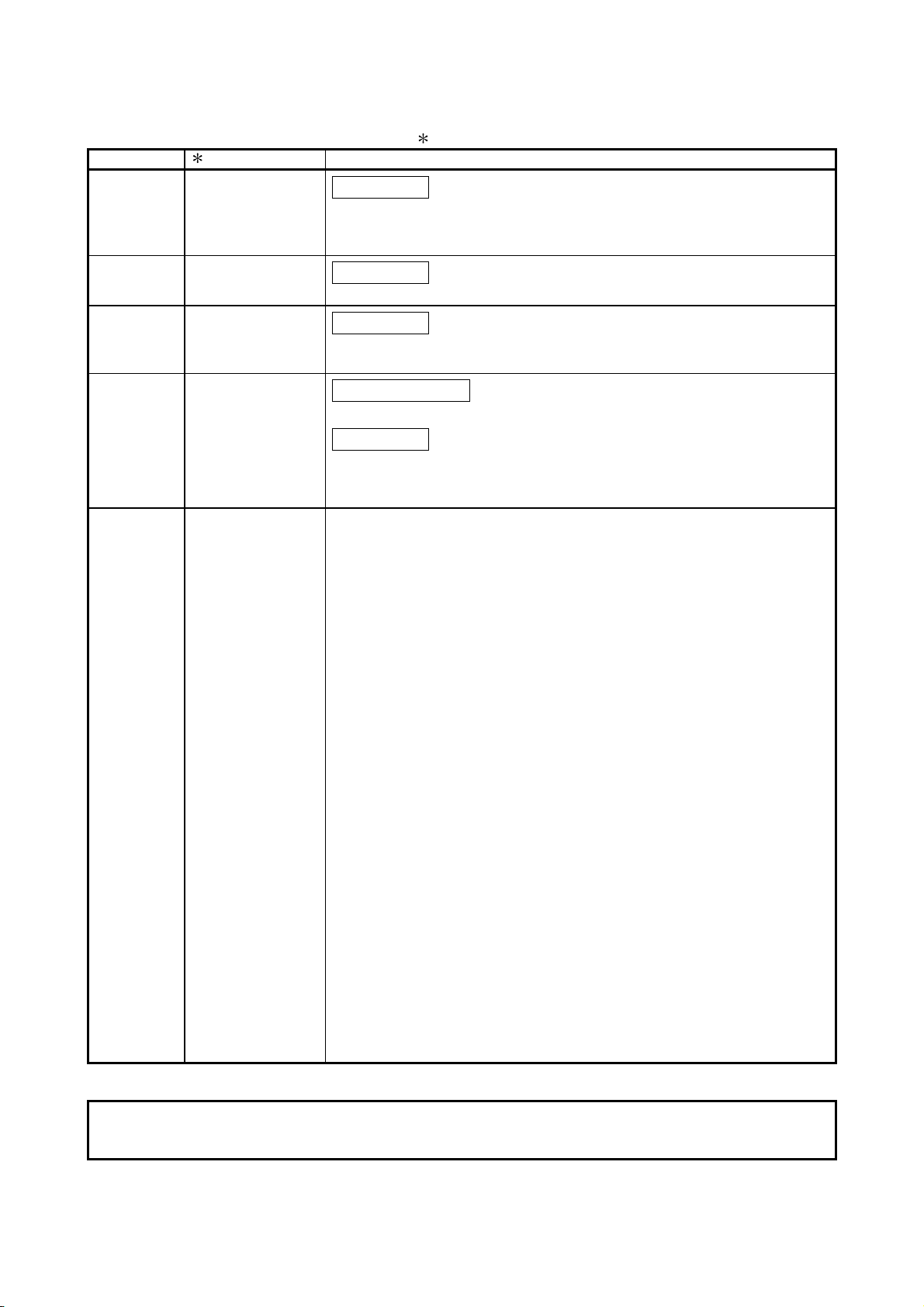
• Structure of this manual
The explanations of the message formats and the control procedures while
communicating through the MC protocol are given in the following format:
[Control procedure]
(1) Reading eight points of data from internal
relays M100 to M107 in communication in
ASCII code
(Refer to Section 3.3.1.)
(Data name)
External device
side
(Example)
(Data name)
Programmable controller
CPU side
(Example)
Command
H--LH- L H----LH--L
04010001M 0001000008
30H34H30H31H30H30H30H31H4DH2AH30H30H30H31H30H30H30H30H30H38
Device code
Subcommand
Number of device points to be read
Head device
An asterisk (
) in both the command message and the response message indicates the same order of data
items as in the control procedures when other commands are used.
Number of points to be read
Number of
device points
H
0 (30H) indicates off
1 (31
(Refer to Section 3.1.5.)
Data for the number of
designed device points
00010010
30H30H30H31H30H30H31H30
M100 = OFF
H) indicates on.
H
M106 = ON
M107 = OFF
This is a description of the
request from the external
device side for the control
procedure explained in the
example.
This diagram illustrates the
sequence of data items in the
command message to be sent
by the external device.
This diagram illustrates the
sequence of data items in the
response message (the
message providing the
processing result) to be sent by
the programmable controller
CPU side for the request sent
from the external device side.
(The head and end sections of the command and response messages.)
Confirm the order of data items in the fields marked with "
" by referring to the reference sections listed
below.
The order of data items in the fields marked with "
" differs between Ethernet interface modules and serial
communication modules.
(1) When communicating via an Ethernet Interface module
A compatible 1E frame : Refer to Section 6.1.
QnA compatible 3E frame : Refer to Section 3.1.2.
4E frame : Refer to Section 3.1.2.
(2) When communicating via a serial communication module
A compatible 1C frame : Refer to Section 5.1.
QnA compatible 2C frame : Refer to Section 4.1.
QnA compatible 3C frame : Refer to Section 3.1.4.
QnA compatible 4C frame : Refer to Section 3.1.5.
A - 16 A - 16
Page 19

GENERIC TERMS AND ABBREVIATIONS
This manual uses the following generic terms and abbreviations to explain the serial communication modules,
Ethernet interface modules, and devices for data communication unless otherwise specified.
(1) Generic terms and abbreviations for CPU modules
Generic term
/abbreviation
ACPU
AnACPU Generic term for A2ACPU, A2ACPU-S1, A2ACPUP21/R21, A2ACPUP21/R21-S1, A3ACPU, A3ACPUP21/R21.
AnA/AnU/QnACPU Generic term for AnACPU, AnUCPU, QnACPU.
AnNCPU
AnUCPU Generic term for A2UCPU, A2UCPU-S1, A2ASCPU, A2ASCPU-S1, A3UCPU, A4UCPU.
AnU/QnACPU Generic term for AnUCPU, QnACPU.
LP25/BR15 Generic term for AJ72LP25, AJ72BR15.
QCPU
QnUDVCPU Generic term for Q03UDVCPU, Q04UDVCPU, Q06UDVCPU, Q13UDVCPU, Q26UDVCPU.
QCPU (A mode) Generic term for Q02CPU-A, Q02HCPU-A, Q06HCPU-A.
Basic model QCPU Generic term for Q00JCPU, Q00CPU, Q01CPU.
High Performance model
QCPU
Process CPU Generic term for Q02PHCPU, Q06PHCPU, Q12PHCPU, Q25PHCPU.
Redundant CPU Generic term for Q12PRHCPU, Q25PRHCPU.
Universal model QCPU
LCPU Generic term for MELSEC-L series CPU modules.
Safety CPU
QCPU station Abbreviation for the programmable controller with QCPU installed.
QE71
QLP21/QBR11 Generic term for AJ71QLP21, AJ71QBR11.
QLP25/QBR15 Generic term for AJ72QLP25 (G), AJ72QBR15, A1SJ72QLP25, A1SJ72QBR15.
QnACPU
QnACPU station Abbreviation for the programmable controller with QnACPU installed.
C24
E71 Abbreviation for QJ71E71-100, QJ71E71-B5, QJ71E71-B2 and LJ71E71-100 Ethernet interface modules.
Serial communication
module
UC24
Computer link module
Generic term for AnNCPU, AnACPU, AnUCPU, QCPU (A mode).
Generic term for A1NCPU, A1NCPUP21/R21, A2NCPU, A2NCPU-S1, A2NCPUP21/R21, A2NCPUP21/R21-S1,
A3NCPU, A3NCPUP21/R21.
Generic term for the Basic model QCPU, High Performance model QCPU, Process CPU, Redundant CPU, and Universal
model QCPU.
Generic term for Q02CPU, Q02HCPU, Q06HCPU, Q12HCPU, Q25HCPU.
Generic term for Q00UJCPU, Q00UCPU, Q01UCPU, Q02UCPU, Q03UDCPU, Q03UDVCPU, Q03UDECPU,
Q04UDHCPU, Q04UDVCPU, Q04UDEHCPU, Q06UDHCPU, Q06UDVCPU, Q06UDEHCPU, Q10UDHCPU,
Q10UDEHCPU, Q13UDHCPU, Q13UDVCPU, Q13UDEHCPU, Q20UDHCPU, Q20UDEHCPU, Q26UDHCPU,
Q26UDVCPU, Q26UDEHCPU, Q50UDEHCPU, Q100UDEHCPU.
Generic term for QS001CPU. When characteristics in common with QCPUs are described, however, it is referred to as
QCPU or Q series CPU.
Generic term for AJ71QE71N3-T, AJ71QE71N-B5, AJ71QE71N-B2, AJ71QE71N-T, AJ71QE71N-B5T,
A1SJ71QE71N3-T, A1SJ71QE71N-B5, A1SJ71QE71N-B2, A1SJ71QE71N-T, A1SJ71QE71N-B5T.
Generic term for Q2ACPU, Q2ACPU-S1, Q2ASCPU, Q2ASCPU-S1, Q2ASHCPU, Q2ASHCPU-S1, Q3ACPU, Q4ACPU,
Q4ARCPU.
Abbreviation for QJ71C24N, QJ71C24N-R2, QJ71C24N-R4, QJ71C24, QJ71C24-R2, LJ71C24 and LJ71C24-R2 serial
communication modules.
Generic term for the modules below.
Q series QJ71C24N, QJ71C24N-R2, QJ71C24N-R4, QJ71C24, QJ71C24-R2.
L series LJ71C24, LJ71C24-R2.
QnA series
Generic term for AJ71UC24, A1SJ71UC24-R2, A1SJ71UC24-R4, A1SJ71UC24-PRF, A1SJ71C24-R2, A1SJ71C24-R4,
A1SJ71C24-PRF, A2CCPUC24, A2CCPUC24-PRF.
For the module model names, refer to the manual for the CPU module used.
Description
A series programmable controller CPUs accessible from external devices using the MC protocol communication
functions.
AJ71QC24, AJ71QC24-R2, AJ71QC24-R4, A1SJ71QC24, A1SJ71QC24-R2, AJ71QC24N,
AJ71QC24N-R2, AJ71QC24N-R4, A1SJ71QC24N, A1SJ71QC24N-R2.
A series computer link module
A - 17 A - 17
Page 20
Generic term/abbreviation Description
User’s Manual (Basic)
User’s Manual (Application)
(2) Generic terms and abbreviations for manuals
• Serial communication module
Q Corresponding Serial Communication Module User’s Manual (Basic)
MELSEC-L Serial Communication Module User’s Manual (Basic)
• Ethernet interface module
Q Corresponding Ethernet Interface Module User’s Manual (Basic)
MELSEC-L Ethernet Interface Module User’s Manual (Basic)
• Serial communication module
MELSEC-Q/L Serial Communication Module User’s Manual (Application)
• Ethernet interface module
MELSEC-Q/L Ethernet Interface Module User’s Manual (Application)
(3) Other generic terms and abbreviations
Generic term/abbreviation Description
Buffer memory
Computer
Data communication function
I/F Abbreviation for Interface.
MELSECNET/10 Abbreviation for MESECNET/10 Network System.
MELSECNET/H Abbreviation for MESECNET/H Network System.
ONDEMAND Abbreviation for G.ONDEMAND or GP.ONDEMAND.
RS-232 (interface) Abbreviation for Interface that conforms to the RS-232 interface.
RS-422/485 (interface) Abbreviation for Interface that conforms to either the RS-422 or RS-485 interface.
Switch setting Generic term for intelligent function module switch setting.
Generic term for the memory of the intelligent function module or special function module
for storing the transmission/reception data when communicating with the programmable
controller CPU (such as setting values and monitor values).
Generic term for a unit in the external device that can communicate data through the MC
protocol or bidirectional protocol.
Generic term for the MC protocol, pre-defined protocol, non-procedure protocol, or
bidirectional protocol.
A - 18 A - 18
Page 21

TERMS
The following table outlines the meanings and descriptions of the terms used in this and relevant manuals of
the Ethernet Interface module.
Term Description
One of the message formats for the serial communication module used to communicate ASCII code
data through the MC protocol.
A-compatible 1C frame
(formats 1 to 4)
A-compatible 1E frame
Bidirectional protocol
Control CPU
Control system CPU In a redundant system, the Redundant CPU on the controlling side.
GX Configurator-SC A setting and monitoring tool for the serial communication module.
GX Developer
GX Works2
Independent operation
Intelligent function module
Intelligent function module
device
Linked operation
MELSEC communication
protocol
(MC protocol)
Message transmission
function
(printer function)
Multidrop connection
MX Component
Non-procedure protocol
Pre-defined protocol
This is the same message format as when communicating through the dedicated protocol for A series
computer link modules.
For a Q/LCPU, reading from and writing to device memories are allowed within the same device range
as for an AnACPU.
One of the message formats for the Ethernet interface module used to communicate ASCII or binary
code data through the MC protocol.
This is the same message format as when reading/writing data from/to the programmable controller
CPU of an A series Ethernet interface module.
For a Q/LCPU, reading from and writing to device memories are allowed within the same device range
as for an AnACPU.
A communication procedure of the serial communication module and one of the data communication
functions of the serial communication module that allow communication of arbitrary data between the
programmable controller CPU and external devices.
The QCPU which controls each I/O module and the intelligent function module.
In a multiple CPU system, a control QCPU can be set for each module.
Product name of the software package for the MELSEC programmable controllers.
Operation of two interfaces of the serial communication module in which each interface performs data
communication with an external device independently of each other, using a function designated in each
transmission protocol setting.
A MELSEC-Q/L series module that has other than input or output, such as A/D converter module and
D/A converter module.
Devices used to directly accesses the buffer memory of the intelligent function module from the CPU
module.
Operation of two interfaces of the serial communication module when they are linked to perform data
communication with external devices that are connected to each of the two interfaces.
The two interfaces perform communication using the same data communication function (MC protocol
(same format) or non-procedure protocol) or the same transmission specifications. (Linked operation
cannot be performed using the bidirectional protocol.)
One of the data communication functions of the serial communication module or Ethernet interface
module used to access the programmable controller CPU from a target device.
(Referred to as the MC protocol in this manual)
Communications with ASCII code data and binary code data are available.
A function that preregisters character data (messages) to be sent to an external device (mainly printers)
in the serial communication module as a user frame, and sends registered data of multiple user frames
using the non-procedure protocol (sent by instruction from the programmable controller CPU).
A mode of connection using the RS-422/485 interface of the serial communication module in which
multiple external devices and other serial communication modules are connected in 1:n or m:n mode.
An Active X® control library for serial communication (MELSOFT product)
A user’s communication procedure, and one of the data communication functions of the serial
communication module for communicating arbitrary data between the programmable controller CPU
and an external device.
One of the data communication functions available for the C24.
This must be set in GX Works2 or GX Configurator-SC (Pre-defined protocol support function).
A - 19 A - 19
Page 22

Term Description
Programming tool Generic term for GX Works2 and GX Developer.
One of the message formats for the serial communication modules used to communicate ASCII code
QnA-compatible 2C frame
(formats 1 to 4)
QnA-compatible 3C frame
(formats 1 to 4)
QnA compatible 4C frame
(formats 1 to 4)
QnA-compatible 3E frame
QnA-compatible 4C frame
(format 5)
SD memory card
Special function module
Special function module
device
Standby system CPU In a redundant system, the Redundant CPU on the standby side prepared for control system failure.
System A CPU
System B CPU
User frame
4E frame
data through the MC protocol.
This is the same message format as the frames for communication through the dedicated protocol of
QnA series serial communication modules.
• QnA compatible 2C frame (formats 1 to 4): QnA simplified frame (formats 1 to 4)
One of the message formats for the serial communication modules used to communicate ASCII code
data through the MC protocol.
This is the same message format as the frame for communication through the dedicated protocol of
QnA series serial communication modules.
• QnA compatible 3C frame (formats 1 to 4): QnA frame (formats 1 to 4)
• QnA compatible 4C frame (formats 1 to 4): QnA extension frame (formats 1 to 4)
One of the message formats for the Ethernet interface modules used to communicate ASCII or binary
code data through the MC protocol.
This is the same message format as when reading/writing data from/to the programmable controller
CPU of a QnA series Ethernet interface module.
One of the message formats for the serial communication modules used to communicate binary code
data through the MC protocol.
This is the same message format as the frame for communication through the dedicated protocol of a
QnA series serial communication module.
• QnA compatible 4C frame (format 5): QnA extension frame (format 5)
Secure Digital Memory Card, which is a flash memory device.
The L1MEM-2GBSD and L1MEM-4GBSD are available.
A MELSEC-A/QnA series module that has other than input or output, such as A/D converter module
and D/A converter module.
Devices used to directly accesses the buffer memory of the special function module from the CPU
module.
In a redundant system, the Redundant CPU on the side to which the system A connector of the tracking
cable is connected.
In a redundant system, the Redundant CPU on the side to which the system B connector of the tracking
cable is connected.
Data name used when registering the fixed format section of a message to be communicated between
the serial communication module and an external device using the functions listed below, in order to use
it for data transmission and reception. (The contents of data in a user frame should be consistent with
the specifications of the external device.)
Used for registering the sequence of data of each of the head and ending sections in a communication
message (transmission control code, C24 station number, sum check, fixed data, etc.) to the serial
communication module.
• The on-demand function of the MC protocol
• Data transmission and reception functions through the non-procedure protocol.
One of the message formats for the Ethernet interface modules, in which ASCII or binary code data are
transferred with the MC protocol.
Any given number (serial No.) for message identification is added to the QnA compatible 3E frame.
By the serial No. which is added by the external device for message identification, the correspondence
between command and response messages can be checked.
A - 20 A - 20
Page 23
1 OVERVIEW
1 OVERVIEW
This manual provides information on the methods that are employed by external
devices to read and write data from/to the programmable controller CPU using the data
communication functions of the MELSEC communication protocol (referred to as the
MC protocol in this manual) via the serial communication modules or Ethernet interface
modules.
When applying the following program examples to the actual system, make sure to
examine the applicability and confirm that it will not cause system control problems.
Operating procedures are explained using GX Developer.
Note that some screen names and items may differ when using GX Works2.
When performing data communication using the MC protocol, please read Chapter 2.
1.1 Overview of the MELSEC Communication Protocol
The following is an overview of the MC protocol:
(1) The MC protocol is the name of a communication method for Q/L series
programmable controller and is used by external devices to read and write device
data and programs of the programmable controller CPU via the C24 or E71.
Communications through the MC protocol can be performed if a device can
incorporate application programs and send/receive data using the control
procedures of the MC protocol.
(2) The message formats and control procedures for an external device to access the
programmable controller CPU are defined separately for the C24 and E71.
QJ71E71
QJ71C24
RUN
PRM
S
T
D LINK
MODE
RUN
N
O
MODE
ERR.
x10010 1
RUN
ERR.
USER
BAT.
BOOT
IN
USB
OUT
RS-232
ERR.
SD
RD
INIT.
COM.ERR
CH1. CH2.
OPEN
RD
SD
10BASE-T
CH1.
RS-232
10BASE
CH.2
SDA
1
SG
2
SDB
(FG)
3
RDA
4
(FG)
5
RDB
+
12V
6
12G
RS-422
7
/485
PULL
MITSUBISHI
Q25HCPU
POWER
MELSEC
1
QJ71E71
QJ71E71
QJ71C24
RUN
PRM
S
T
MODE
D LINK
RUN
N
O
MODE
ERR.
x10010 1
RUN
ERR.
USER
BAT.
BOOT
IN
USB
OUT
RS-232
ERR.
SD
RD
INIT.
COM.ERR
CH2.
CH1.
OPEN
SD
RD
10BASE-T
CH1.
RS-232
10BASE
CH.2
SDA
1
SG
2
SDB
(FG)
3
RDA
4
(FG)
5
RDB
+
12V
6
12G
RS-422
7
/485
PULL
MITSUBISHI
Q25HCPU
POWER
MELSEC
Q25HCPU
MELSEC
POWER
PULL
MITSUBISHI
QJ71C24
RUN
PRM
S
T
MODE
D LINK
RUN
N
O
MODE
ERR.
x100101
RUN
ERR.
USER
BAT.
BOOT
IN
USB
OUT
RS-232
ERR.
SD
RD
INIT.
COM.ERR
CH2.
CH1.
OPEN
SD
RD
10BASE-T
CH1.
RS-232
10BASE
CH.2
SDA
1
SG
2
SDB
(FG)
3
RDA
4
(FG)
5
RDB
+
12V
6
12G
RS-422
7
/485
(3) The message formats and control procedures during data communication using
the MC protocol are the same as when accessing the programmable controller
E
N
Q
HL HL H L H L
0001QR 0 X000040 0 227
05H30H30H30H31H51H52H30H58H30H30H30H30H34H30H30H32H37H32
(Command message of the A compatible 1C frame) (Response message of the A compatible 1C frame)
CPU via conventional A/QnA series modules.
Number of
Sum
check
code
H
Station
number
PC number
Command
Head device
Message wa it
device point s
2 characters
(hexadecima l)
S
T
X
02H30H30H30H31H31H32H33H34H42H43H44
Data for the number
of device points
Station
number
HL H L
000 11234 BCD
device points
X 4 characters
PC number
Number of
A
H
41
Sum
E
check
T
code
X
HL
9
8
H
H
H
39H38
03
1 - 1 1 - 1
Page 24

1
An external device can access a Q/L series programmable controller using a program
with which the programmable controller is accessed via one of the following A/QnA
series modules.
1) Accessing the programmable controller via the C24
It is possible to access the programmable controller using a program
on the external device via the following A/QnA series modules.
• A series computer link module
• QnA series serial communication module
2) Accessing the programmable controller via the E71
It is possible to access the programmable controller using a program
on the external device via the following A/QnA series modules.
• A series Ethernet interface module
• QnA series Ethernet interface module
The data communication functions using the MC protocol correspond
to the following data communication function of the conventional
modules.
• In case of the C24
Corresponds to the data communication functions using the
dedicated protocol supported by A series computer link modules and
QnA series serial communication modules.
• In case of the E71
Corresponds to the functions for reading/writing data from/to the
programmable controller CPU supported by A series/QnA series
Ethernet interface modules.
(4) At the programmable controller CPU side, the C24/E71 sends/receives data
according to the commands from an external device.
Thus, a sequence program for data communication is not required at the
programmable controller CPU side.
In case of the C24, a sequence program for data communication is required
when using the on-demand function for sending data from the programmable
controller CPU.
(5) If the external device is a personal computer, it is possible to create a
communication program for the external device without considering the message
formats or transmission/reception procedures of the MC protocol by using a
separately-available communication support tool (MX Component).
Depending on the version of MX Component used, different operating
systems are supported.
For details, refer to the MX Component manual.
1 OVERVIEW
1 - 2 1 - 2
Page 25

1.2 Features of the MELSEC Communication Protocol
This section explains the features of the MC protocol.
(1) The data communication using the MC protocol is a function that enables the
reading/writing of data from/to the programmable controller CPU in order to
control and monitor the programmable controller equipment from the external
device side.
Reading/writing device data and program files for the programmable controller
CPU and controlling the programmable controller CPU status (remote
RUN/STOP) can be performed from the external devices (personal computer,
indicator, etc.)
(a) Reading and writing data
By reading/writing data to/from the device memory of the programmable
controller CPU and the buffer memory of the intelligent function modules,
the following control operations can be performed:
Data read and write operations can also be performed for A/QnA series
programmable controller CPUs (other stations) and intelligent function
modules.
1) Reading data
Operation monitoring, data analysis, production control, etc. can be
performed from the external device side.
2) Writing data
Production instructions, etc. can be issued from the external device
side.
(b) Reading and writing files
By reading and writing files for sequence programs and parameters stored
in the programmable controller CPU, the following control operations can
be performed:
1) Reading files
File management for the local station’s QCPU/LCPU and other station'
QCPU/LCPU/QnACPU can be performed from the external device
side.
2) Writing files
Programs such as execution programs can be modified (replaced) by
writing file data stored in the external device to the programmable
controller CPU as needed.
(c) Remote control of the programmable controller CPU
The programmable controller CPU can be remotely controlled from the
external device by performing remote RUN/STOP/PAUSE/LATCH
CLEAR/RESET operations.
1 OVERVIEW
1 - 3 1 - 3
Page 26
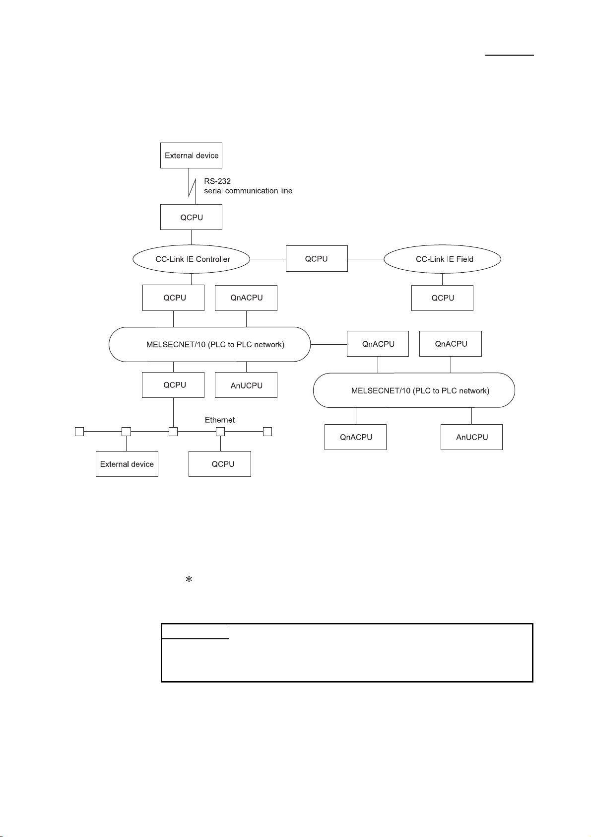
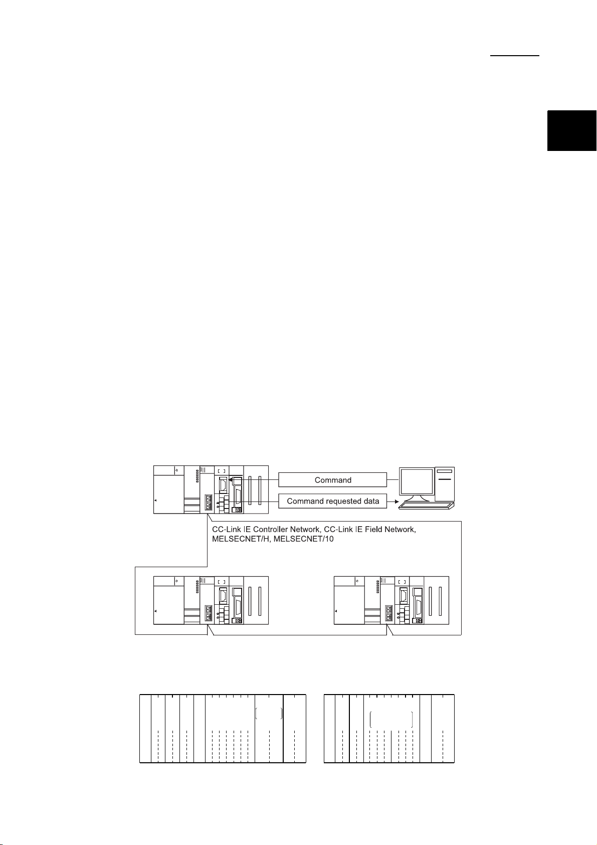
(2) In a system using -Link IE Controller Network, CC-Link IE Field Network,
MELSECNET/H, MELSECNET/10, and Ethernet, an external device can access
programmable controller CPUs of other stations over the respective network.
1 OVERVIEW
(3) The C24 is equipped with the programmable controller CPU monitoring function.
By using this function, the programmable controller CPU status and data in the
device memory can be sent to an external device at constant intervals, upon the
occurrence of a mechanical error, or when certain conditions are satisfied.
This helps reduce the number of data read processes performed by the external
device.
The E71 also has the programmable controller CPU monitoring function that
uses e-mail transmission.
(Refer to the User's Manual (Application).)
POINT
To check what functions can be performed by external devices when
communicating data through the MC protocol, refer to the "Commands and function
list" reference sections in Chapters 3 to 6.
1 - 4 1 - 4
Page 27
2 DATA COMMUNICATION USING THE MELSEC COMMUNICATION PROTOCOL
2 DATA COMMUNICATION USING THE MELSEC COMMUNICATION
PROTOCOL
This chapter explains the data communication using the MC protocol when an external
device reads data from and writes data to a programmable controller CPU using the
C24/E71.
2.1 Types and Applications of Data Communication Frames
This section provides information about the types and applications of frames (data
communication messages) used by the external device to access the programmable
controller CPU using the MC protocol.
When the external device accesses the programmable controller via the C24/E71, the data
communication is performed by transmission/reception of command messages (access
requests) and response messages (responses) of one of the following frames listed below.
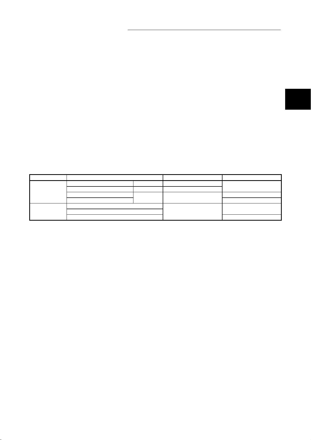
Choose the frame to be used by considering the accessible range of each frame
Target module Available communication frame Code of communication data Control procedure reference section
QnA compatible 3C frame Formats 1 to 4 ASCII code
C24
E71
QnA compatible 4C frame Format 5 Binary code
QnA compatible 2C frame Chapter 4
A compatible 1C frame
4E frame
QnA compatible 3E frame
A compatible 1E frame
shown in Section 2.2.
Chapter 3
Formats 1 to 4 ASCII code
ASCII code or binary code
Chapter 5
Chapter 3
Chapter 6
(1) QnA compatible 3C, QnA compatible 4C and QnA compatible 3E
frames
(a) These frames are mainly used to access all devices and files of the
Q/L/QnACPU from the external device.
(b) These frames enable access to A series programmable controller devices
also through CC- Link IE Controller Network, CC-Link IE Field Network,
MELSECNET/H, MELSECNET/10, and Ethernet. (Refer to Section 2.2 (1))
(2) 4E frame
(a) These frames are mainly used to access all devices and files of the Q/LCPU
from the external devices.
(b) These frames enable access to A/QnA series programmable controller
devices also through CC- Link IE Controller Network, CC-Link IE Field
Network, MELSECNET/H, MELSECNET/10, and Ethernet. (Refer to
Section 2.2 (2))
(3) QnA compatible 2C frame
(a) This frame can access the device memory of QCPU/LCPU stations on which
the C24 is loaded and Q/L/QnACPU stations linked by multidrop connection.
(b) The message format is simplified compared to the QnA compatible
3E/3C/4C frames.
(c) Since smaller amounts of transmission data are used, the messages are
easier to be processed by the external device and the transmission times of
the messages are shortened.
2
2 - 1 2 - 1
Page 28

2
(4) A compatible 1C and A compatible 1E frames
(a) These frames have the same message structure as when accessing the
programmable controller CPU using an A series computer link module or
Ethernet interface module.
(b) By utilizing the software for data communication on the external device that
has been created for the A series programmable controllers, Q/L/QnACPUs
linked by multidrop connection or network connection, and programmable
controller CPUs other than Q/L/QnACPU can be accessed using the same
frame.
With respect to the Q/L/QnACPUs, only those devices with the same
names as those existing in the AnCPUs, AnNCPUs, AnACPUs and
AnUCPUs can be accessed within the AnACPU device range.
• When using the C24 : Refer to Section 5.2.1(2)
• When using the E71 : Refer to Section 6.3.1(2)
Devices that have been newly added to Q/L/QnACPUs cannot be accessed.
(c) To access a Universal model QCPU, the serial No. (first five digits) of the
module must be 10102 or later.
If the serial No. (first five digits) is 10101 or earlier, make access using the
QnA compatible 2C/3C/4C frame, QnA compatible 3E frame, or 4E frame.
2 DATA COMMUNICATION USING THE MELSEC COMMUNICATION PROTOCOL
REMARKS
(1) The following explains how to read the data communication frame names
when performing data communication using the MC protocol.
A data communication frame name indicates a relevant programmable
controller CPU series to show command compatibility with conventional
modules, a frame designation of the corresponding conventional module, and
the target module.
xxx compatible n m frame
a) b) c)
(Examples: QnA compatible 3C frame, QnA compatible 3E frame)
(a) Relevant programmable controller CPU series, showing command
compatibility with conventional modules
A : A series programmable controller CPU
QnA : QnA series programmable controller CPU
(b) Frames of the corresponding conventional modules
1 : Corresponds to the communication frames of commands supported
by A series computer link modules and Ethernet interface modules.
2 : Corresponds to the QnA simplified frames supported by QnA
series serial communication modules.
3 : Corresponds to the QnA frames supported by QnA series serial
communication modules and the communication frames supported
by QnA series Ethernet interface modules.
4 : Corresponds to the QnA extension frames supported by QnA
series serial communication modules.
(c) Modules described in this manual with which data communication can be
performed using the applicable frames.
C : C24
E : E71
2 - 2 2 - 2
Page 29
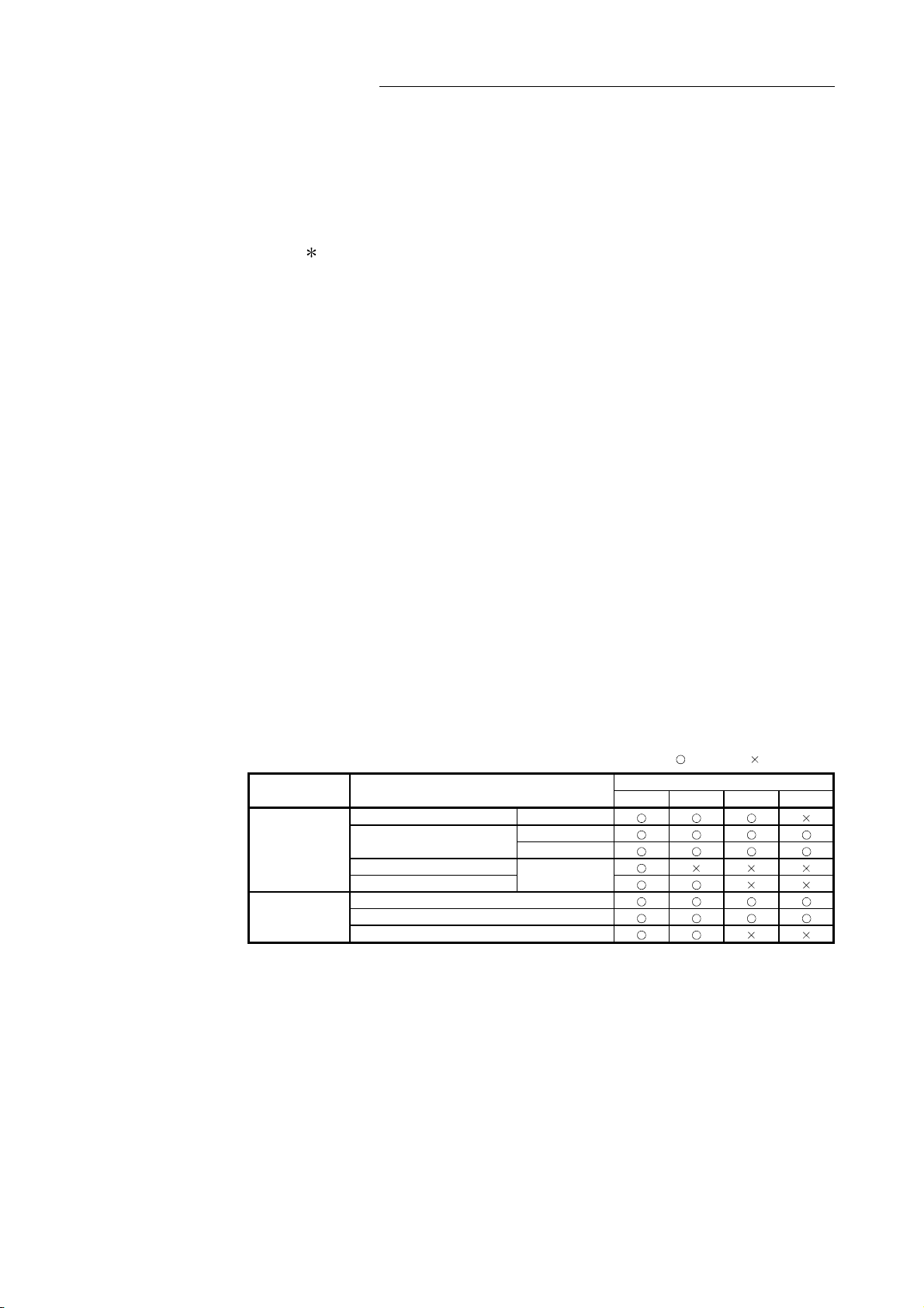
2 DATA COMMUNICATION USING THE MELSEC COMMUNICATION PROTOCOL
(2) When accessing via the C24
The external device accesses the programmable controller CPU using frames
with a format number selected in the "Communication protocol setting" in the
switch settings using the programming tool.
When any of Formats 1 to 4 is selected, access is enabled using each of the
four types of frames shown above and data communication is performed by
the transmission/reception of command messages and response messages
in the selected format.
(3) When accessing via the E71
The external device can access using any of the two types of frames shown
above; it accesses the programmable controller CPU by sending/receiving
command messages and response messages using frames corresponding to
the setting selected in the operation settings using the programming tool.
(4) Time required for communication in binary code is shortened because the
amount of the communication data is approximately a half of what is required
for communication in ASCII code data.
2.2 Accessible Range of Each Data Communication Frames
In a communication using the MC protocol, access to programmable controller stations
on which the C24/E71 is not loaded is possible via CC-Link IE Controller Network,
CC-Link IE Field Network, MELSECNET/H, MELSECNET/10 and Ethernet.
This section explains the range of programmable controllers of other stations that can
be accessed from an external communication device when the access destination
programmable controller is not directly connected by a serial communication line or
Ethernet.
Target module Frame used
QnA compatible 3C frame Formats 1 to 4
C24
E71
QnA compatible 4C frame
QnA compatible 2C frame
A compatible 1C frame
4E frame
QnA compatible 3E frame
A compatible 1E frame
Formats 1 to 4
Format 5
Formats 1 to 4
: Accessible, : Not accessible
Range of accessible stations
1) 2) 3) 4)
2 - 3 2 - 3
Page 30
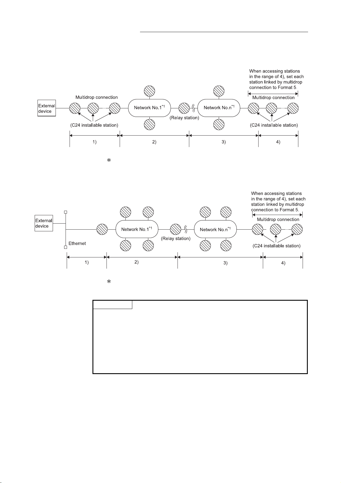
(1) When using the C24
1 The network represents CC-Link IE Controller Network,
CC-Link IE Field Network, MELSECNET/H, MELSECNET/10, or Ethernet.
(2) When using the E71
2 DATA COMMUNICATION USING THE MELSEC COMMUNICATION PROTOCOL
1 The network represents CC-Link IE Controller Network, CC-Link IE Field
Network, MELSECNET/H, MELSECNET/10, or Ethernet.
POINT
By setting the routing parameter (communication path) in advance, access to
programmable controllers on the following network systems is also available.
• CC-Link IE Controller Network
• CC-Link IE Field Network
• MELSECNET/H
• MELSECNET/10
• Ethernet
Accessible range is up to the eighth network (number of relay stations: 7).
2 - 4 2 - 4
Page 31

2 DATA COMMUNICATION USING THE MELSEC COMMUNICATION PROTOCOL
2.3 How to Read the Control Procedures of the MC Protocol
This section explains the control procedures when an external device accesses the
programmable controller CPU using the MC protocol.
(1) Transmission of command messages
Data communication through the MC protocol is performed using half-duplex
communication. (
When accessing the programmable controller CPU, send the next command
message after receiving a response message from the programmable controller
CPU side for the previous command message transmission.
1)
External device side
Programmable
controller CPU side
(Command message)
(Response message)
(Command message)
(Response message)
1 When accessing via the C24, full-duplex communication is performed by
user setting when the on-demand function is being used.
When the system between external devices and programmable controller
CPUs is configured with a m:n connection, the next command message
transmission cannot be performed until data communication between either
of the external devices and programmable controller CPUs is completed.
(2) When a normal completion response message to a command
message cannot be received
(a) If an abnormal completion response message is received
Handle the case according to the error code in the response message.
(b) If the response message cannot be received or nothing can be received
• Via the E71
Send the command message again after the monitoring time of the
response monitor timer value has elapsed.
• Via the C24
Send the command message again after the monitoring time of the
response monitor timer (timer 1) has elapsed.
Modify the setting value of the monitoring time as needed.
In case of via the C24, try to modify the message wait time also.
2 - 5 2 - 5
Page 32

2 DATA COMMUNICATION USING THE MELSEC COMMUNICATION PROTOCOL
2.4 Access Timing of the Programmable Controller CPU Side
The following diagram illustrates the access timing of the programmable controller
CPU side when an external device accesses the programmable controller CPU via the
C24/E71.
1) A command message is transmitted from the external device to the
programmable controller CPU side.
2) Upon receiving a command message from the external device, the
C24/E71 of the programmable controller CPU side sends a data
read/write request to the programmable controller CPU according to
the content of the command.
3) The programmable controller CPU reads/writes data according to the
request from the external device at the time of executing the sequence
program’s END instruction, and passes the processing result to the
C24/E71.
4) Upon receiving the processing result from the programmable controller
CPU, the C24/E71 sends a response message including the
processing result to the external device that originated the request.
1 The ACK response shown in the diagram is sent/received between the
E71 and the external device when the access via the E71 is performed
by TCP/IP communication.
It is different from the response to the processing requested by the
external device in the command message (the processing result).
When access via the E71 is performed by UDP/IP or when access is
performed via the C24, the ACK response indicated by
1 is not sent.
2 - 6 2 - 6
Page 33

POINT
(1) Note that when data is read/written from/to the external device while the
programmable controller CPU is in operation, the scan time of the
programmable controller CPU increases for the amount of time it takes to
process the command from the external device.
If the increase in scan time affects the operations of the programmable
controller CPU, access the CPU module multiple times by dividing the points.
(2) An access request from the external device to the buffer memory of the
C24/E71 is immediately acknowledged. Also, it does not affect the scan time
of the programmable controller CPU.
2 DATA COMMUNICATION USING THE MELSEC COMMUNICATION PROTOCOL
REMARKS
Regarding the scan time of the programmable controller CPU
(1) While the programmable controller CPU is performed by required command,
access command to the C24/E71 and the programmable controller CPU is
processed during every END processing.
(The scan time becomes longer according to the amount of time it takes to
process the command.)
(2) When multiple external devices issue access requests to a single station at the
same time, the processing requested from the external devices may have to
wait until END processing has been executed multiple times depending on the
timing of the requests.
Multiple command requests can be processed within one scan by using any of
the following methods. Note that, however, these methods are not available for
safety CPUs.
(a) Using the COM instruction
On the sequence program, execute the COM instruction.
For details of the COM instruction, refer to the Programming Manual
(Common Instructions) for the CPU module used.
(b) Using the Time reserved for communication processing (SD315) (for the
Basic model QCPU, High Performance model QCPU, Process CPU, and
Redundant CPU)
With the Time reserved for communication processing (SD315), set a time
value for communication processing within the range of 1ms to 100ms.
(c) Using the service processing setting (for the Universal model QCPU and
the LCPU)
Under the "Service processing setting" on the PLC system tab of PLC
parameter, set a time value for service processing within the range of 1ms
to 100ms.
2 - 7 2 - 7
Page 34

2 DATA COMMUNICATION USING THE MELSEC COMMUNICATION PROTOCOL
2.5 Setting Method for Writing to the Programmable Controller CPU during RUN
This section explains the setting for writing data from an external device to the running
programmable controller CPU via the C24/E71.
(1) Setting of the C24
Enable the "Online Change" setting of the transmission setting in the intelligent
function module switch setting screen using the programming tool.
For the switch setting, refer to the User’s Manual (Basic) for the C24 used.
(2) Setting of the E71
Check the "Enable Write at RUN time" checkbox in the Ethernet operation setting
screen using the programming tool.
For the operation setting, refer to the User’s Manual (Basic) for the E71 used.
(3) Setting on the programmable controller CPU side
Set the system protect switch to the "Enable write at programmable controller
CPU RUN time".
(In case of a QCPU (excluding Universal model QCPU), set the system
protection switch, SW1, to "OFF".)
POINT
When connecting a peripheral with the programmable controller CPU or connecting
an external device, such as a personal computer, with an intelligent function
module to modify data of a running programmable controller, configure an interlock
circuit in the program to ensure that the entire system will always operate safely.
For other forms of control (such as program modification or operating status
change) of a running programmable controller, read the relevant manuals carefully
and ensure that the operation is safe before proceeding.
Especially, when a remote programmable controller is controlled by an external
device, immediate action cannot be taken if a problem occurs in the programmable
controller due to a communication failure. To prevent this, configure an interlock
circuit in the sequence program, and determine corrective actions to be taken
between the external device and CPU module in case of a communication failure.
2 - 8 2 - 8
Page 35

2 DATA COMMUNICATION USING THE MELSEC COMMUNICATION PROTOCOL
2.6 Accessing Other Stations
This section provides an overview on how to access programmable controllers of other
stations that are connected via CC-Link IE Controller Network, CC-Link IE Field
Network, MELSECNET/H, MELSECNET/10 and Ethernet.
2.6.1 Accessible programmable controllers of other stations
The following tables summarize the accessible modules and modules that can act as
message relays in a network when accessing programmable controllers of other
stations (applicable stations whose designated PC number in the data communication
frames is not FF
H.)
(1) Accessible modules
(a) Programmable controller CPU modules
Model name
Basic model Q00JCPU, Q00CPU, Q01CPU
High performance
model
Process CPU Q02PHCPU, Q06PHCPU, Q12PHCPU, Q25PHCPU
QCPU
LCPU2
Safety CPU3
QnACPU
Redundant CPU Q4ARCPU
ACPU4
Redundant CPU Q12PRHCPU, Q25PRHCPU
Universal model
1 2
QCPU
1 For application of the A compatible 1C/1E frame, use a Universal model QCPU whose serial
No. (first five digits) is 10102 or later.
If the serial No. (first five digits) is 10101 or earlier, make access using the QnA compatible
2C/3C/4C frame, QnA compatible 3E frame, 4E frame.
2 To access the built-in Ethernet port of the CPU module, refer to the following.
• QnUCPU User’s Manual (Communication via Built-in Ethernet Port)
• MELSEC-L CPU Module User's Manual (Built-In Ethernet Function)
3 Safety CPU modules whose serial No. (first five digits) is 13041 or earlier can be used only on
an access target station; they cannot be used on relay stations.
4 Safety CPU modules cannot relay data to ACPU modules. They cannot access a safety CPU
module through an ACPU or QnACPU module.
5 Other than the programmable controller CPUs above, it is possible to access A2CCPUC24 and
A2CCPUC24-PRF modules that are linked to an external device by multidrop connection.
Q02CPU, Q02HCPU, Q06HCPU, Q12HCPU, Q25HCPU
Q00UJCPU, Q00UCPU, Q01UCPU, Q02UCPU, Q03UDCPU, Q03UDVCPU,
Q03UDECPU, Q04UDHCPU, Q04UDVCPU, Q04UDEHCPU, Q06UDHCPU,
Q06UDVCPU, Q06UDEHCPU, Q10UDHCPU, Q10UDEHCPU, Q13UDHCPU,
Q13UDVCPU, Q13UDEHCPU, Q20UDHCPU, Q20UDEHCPU, Q26UDHCPU,
Q26UDVCPU, Q26UDEHCPU, Q50UDEHCPU, Q100UDEHCPU
L02SCPU, L02CPU, L26CPU, L26CPU-BT, L02CPU-P, L26CPU-PBT
QS001CPU
Q2ACPU, Q2ACPU-S1, Q2ASCPU, Q2ASCPU-S1, Q2ASHCPU,
Q2ASHCPU-S1, Q3ACPU, Q4ACPU
A1NCPU, A2NCPU, A2NCPU-S1, A3NCPU, A2ACPU, A2ACPU-S1, A3ACPU,
A2UCPU, A2UCPU-S1, A3UCPU, A4UCPU, A1SCPU(-S1), A1SJCPU(-S3),
A1SHCPU, A1SJHCPU, A2SCPU(-S1), A2SHCPU(-S1), A2USCPU,
A2USCPU-S1, A2ASCPU, A2ASCPU-S1, A2ASCPU-S30, A2ASCPU-S60,
A2USHCPU-S1, A0J2HCPU, Q02CPU-A, Q02HCPU-A, Q06HCPU-A
2 - 9 2 - 9
Page 36

2 DATA COMMUNICATION USING THE MELSEC COMMUNICATION PROTOCOL
(b) CC-Link IE Field Network
Model name
Head Module LJ72GF15-T2
(c) MELSECNET/H, MELSECNET/10
Model name
MELSECNET/H
remote I/O station
MELSECNET/10
remote I/O station
6 Only reading/writing of the intelligent function module’s buffer memory is available for the
QJ72LP25-25, QJ72LP25G, QJ72LP25GE, QJ72BR15
AJ72QLP25(G), AJ72QBR15, A1SJ72QLP25, A1SJ72QBR15, AJ72LP25(G/GE),
6
AJ72BR15
MELSECNET/10 remote I/O stations.
POINT
When writing data to the device in the remote I/O station or the intelligent function
module (special function module) mounted on the remote I/O station module within
the network system, enable online change according to the methods described in
Section 2.5 (1) (2).
2 - 10 2 - 10
Page 37

2 DATA COMMUNICATION USING THE MELSEC COMMUNICATION PROTOCOL
(2) Modules that can act as relays between the networks
Model name
CC-Link IE Controller
Network
CC-Link IE Field
Network
MELSECNET/H
MELSECNET/10
Ethernet (1)
1 QnA series Ethernet interface modules can act as relays between the networks if the function version
QJ71GP21-SX, QJ71GP21S-SX
QJ71GF11-T2, LJ71GF11-T2, QS0J71GF11-T2
QJ71LP21, QJ71LP21-25, QJ71LP21S-25, QJ71LP21G, QJ71LP21GE, QJ71BR11,
QJ71NT11B (MELSECNET/H mode)
QJ71LP21, QJ71LP21-25, QJ71LP21S-25, QJ71LP21G, QJ71LP21GE, QJ71BR11
(MELSECNET/10 mode)
AJ71QLP21(S/G), AJ71QBR11, A1SJ71QLP21(S/GE), A1SJ71QBR11
AJ71LP21(G/E), AJ71BR11, A1SJ71LP21(GE), A1SJ71BR11
QJ71E71-100, QJ71E71-B5, QJ71E71-B2, QJ71E71
LJ71E71-100
AJ71QE71N3-T, AJ71QE71N-B5, AJ71QE71N-B2, AJ71QE71N-T, AJ71QE71N-B5T,
A1SJ71QE71N3-T, A1SJ71QE71N-B5, A1SJ71QE71N-B2, A1SJ71QE71N-T,
A1SJ71QE71N-B5T, AJ71QE71, AJ71QE71-B5 A1SJ71QE71-B2, A1SJ71QE71-B5
is B or later.
Verify the function version by the production date shown in the "Date column of the rated plate" which
is attached to the side of the module.
(Manufactured date: Year (last two digits), Month (two digits), function version (one digit))
POINT
(1) When accessing other stations using A compatible 1E/1C frames, set the
following parameter to the programmable controller CPU on the station where
the C24/E71 is loaded using the programming tool.
• The "Valid module during other station access" setting:
Sets the routing module when accessing other stations.
(2) When multiple network modules with the same network number are loaded on
the C24/E71 installable station, access to other stations is performed via the
network module installed on the slot that has the smallest base unit number.
(3) For the number of scans required when multiple external devices and
programming tools simultaneously request accesses to the same station,
refer to Section 2.4.
(4) For the details of the accessible range of programmable controllers of other
stations on a network system, refer to the manual for the network system
being used.
(5) If a computer link module is included in a multidrop connection when
connecting to the C24, it should be accessed using ASCII code
communication frames.
The QnA compatible 4C frame (format 5) for binary code communication
cannot be used when accessing stations linked via multidrop connection,
including when accessing stations connected to an external device.
(6) When the E71 is connected, the external device can communicate with a
programmable controller CPU on another station over the following networks.
• CC-Link IE Controller Network
• CC-Link IE Field Network
• MELSECNET/H
• MELSECNET/10
For more details, refer to the User’s Manual (Application).
2 - 11 2 - 11
Page 38

2 DATA COMMUNICATION USING THE MELSEC COMMUNICATION PROTOCOL
2.6.2 Example of accessible station when each frame is used
The following examples show some other stations whose programmable controllers
are accessible.
In the diagrams, the following symbols are used for each station.
When the E71 is included in a network system, it is configured as a normal
station (the "Ns" symbol above).
2 - 12 2 - 12
Page 39

2 DATA COMMUNICATION USING THE MELSEC COMMUNICATION PROTOCOL
(When stations connected to external devices are the Q/L/QnACPUs)
2 - 13 2 - 13
Page 40

External device connection station
A compatible 1E frame
A compatible 1C frame
QnA compatible 2C frame
QnA compatible 3E frame
4E frame
1)
QnA compatible 3C frame
QnA compatible 4C frame
(formats 1 to 4)
QnA compatible 4C frame
(format 5)
A compatible 1E frame
A compatible 1C frame
QnA compatible 2C frame
QnA compatible 3E frame
4E frame
2)
QnA compatible 3C frame
QnA compatible 4C frame
(formats 1 to 4)
QnA compatible 4C frame
(format 5)
A compatible 1E frame
A compatible 1C frame
QnA compatible 2C frame
QnA compatible 3E frame
4E frame
3)
QnA compatible 3C frame
QnA compatible 4C frame
(formats 1 to 4)
QnA compatible 4C frame
(format 5)
A compatible 1E frame
A compatible 1C frame
QnA compatible 2C frame
QnA compatible 3E frame
4E frame
4)
QnA compatible 3C frame
QnA compatible 4C frame
(formats 1 to 4)
QnA compatible 4C frame
(format 5)
2 DATA COMMUNICATION USING THE MELSEC COMMUNICATION PROTOCOL
Station accessible from an external device
2Mp1
2Ns3
3M
R
1Mp1 1N2 1Ns3
1Ns4
2Ns2
2Ns4
3R1 3R2 3R3 4Ns1 4R2 4R3
4MR0
: Accessible, : ( 1), : Not accessible
(Continued to the next page)
2 - 14 2 - 14
Page 41

External device connection station
A compatible 1E frame
A compatible 1C frame
QnA compatible 2C frame
QnA compatible 3E frame
5)
4E frame
to
QnA compatible 3C frame
6)
QnA compatible 4C frame
(formats 1 to 4)
QnA compatible 4C frame
(format 5)
A compatible 1E frame
A compatible 1C frame
QnA compatible 2C frame
QnA compatible 3E frame
4E frame
7)
QnA compatible 3C frame
QnA compatible 4C frame
(formats 1 to 4)
QnA compatible 4C frame
(format 5)
2 DATA COMMUNICATION USING THE MELSEC COMMUNICATION PROTOCOL
Station accessible from an external device
1Mp1 1N2 1Ns3
1Ns4
2Ns2
2Mp1
2Ns3
3M
2Ns4
R
3R1 3R2 3R3 4Ns1 4R2 4R3
4MR0
1 There are limits to the devices and their ranges that can be accessed to the Q/L/QnACPU using the A
compatible 1E frame or A compatible 1C frame.
With respect to the Q/L/AnACPU, only those devices with the same name as those existing in the
AnCPU, AnNCPU, AnACPU and AnUCPU can be accessed within the AnACPU device range.
• When using the C24: Refer to section 5.2.1 (2)
• When using the E71: Refer to section 6.3.1 (2)
Devices that have been newly added with the Q/L/QnACPU cannot be accessed.
: Accessible, : ( 1), : Not accessible
2 - 15 2 - 15
Page 42

2 DATA COMMUNICATION USING THE MELSEC COMMUNICATION PROTOCOL
2.6.3 Example of designating data items for accessing other station designated within each data communication frame
This section shows examples of designating the "Network number", "PC number",
"Request destination module I/O number" and "Request destination module station
number" that are designated in each frame when accessing to the programmable
controller station on the CC-Link IE Controller Network, CC-Link IE Field Network,
MELSECNET/H, MELSECNET/10 using the MC protocol.
For items to be specified by data, refer to Section 3.1.
(How to understand the diagram and tables)
• Refer to Section 2.6.2 for the meaning of symbols used in explanations.
• The numbers in the "Designated value when accessing from an external device"
columns indicate the values designated for the data items shown in the left side
of the table when accessing the relevant programmable controller station on the
network system shown in the upper row of the table.
2 - 16 2 - 16
Page 43

Data name
Network number
Mp
PC number
Mp
Request destination module I/O No.
Spm
Request destination module station No.
Spm
When the external device connection station is 1)
Data name
Network number
Mp
PC number
Mp
Request destination module I/O No.
Spm
Request destination module station No.
Spm
When the external device connection station is 2)
Data name
Network number
Mp
PC number
Mp
Request destination module I/O No.
Spm
Request destination module station No.
Spm
When the external device connection station is 3)
Data name
Network number
Mp
PC number
Mp
Request destination module I/O No.
Spm
Request destination module station No.
Spm
When the external device connection station is 4)
2 DATA COMMUNICATION USING THE MELSEC COMMUNICATION PROTOCOL
Designated value when accessing from an external device
1Mp1 1N2 1Ns3
H 01H 02H 03H 04H
00
H 02H 03H 04H 01H 03H 04H 01H 02H 03H 01H 02H 03H
FF
1Ns4/
2Ns2
Designated value when accessing from an external device
1Mp1 1N2 1Ns3
H 00H 02H 03H 04H
01
H 02H 03H FFH 01H 03H 04H 01H 02H 03
01
1Ns4/
2Ns2
Designated value when accessing from an external device
1Mp1 1N2 1Ns3
H 02H 00H 02H 03H 04H
01
H 02H 03H 02H 01H FFH 04H 01H 02H 03
01
1Ns4/
2Ns2
Designated value when accessing from an external device
1Mp1 1N2 1Ns3
H 02H 03H 02H 00H 03H 04H
01
01
H 02H 03H 02H 01H 7DH 04H FFH 02H 03
1Ns4/
2Ns2
2Mp1
2Mp1
2Mp1
2Mp1
2Ns3/
3M
2Ns3/
3M
2Ns3/
3M
2Ns3/
3M
2Ns4/
R
R
R
R
3R1 3R2 3R3 4Ns1 4R2 4R3
4MR0
H
03FF
H
00
2Ns4/
3R1 3R2 3R3 4Ns1 4R2 4R3
4MR0
01H 02H 03H
H
H
03FF
H
00
2Ns4/
3R1 3R2 3R3 4Ns1 4R2 4R3
4MR0
01H 02H 03H
H
H
03FF
H
00
2Ns4/
3R1 3R2 3R3 4Ns1 4R2 4R3
4MR0
01H 02H 03H
H
03FF
H
00
H
2 - 17 2 - 17
Page 44

Data name
Network number
Mp
PC number
Mp
Request destination module I/O No.
Spm
Request destination module station No.
Spm
When the external device connection station is 5)
Data name
Network number
Mp
PC number
Mp
Request destination module I/O No.
Spm
Request destination module station No.
Spm
When the external device connection station is 6)
Data name
Network number
Mp
PC number
Mp
Request destination module I/O No.
Spm
Request destination module station No.
Spm
When the external device connection station is 7)
2 DATA COMMUNICATION USING THE MELSEC COMMUNICATION PROTOCOL
Designated value when accessing from an external device
1Mp1 1N2 1Ns3
H 02H 02H 04H 03H 00H 04H
01
H 02H 03H 02H 01H 03H 7DH 01H 02H 03H FFH 02H 03H
01
1Ns4/
2Ns2
Designated value when accessing from an external device
1Mp1 1N2 1Ns3
H 02H 02H 00H 03H 04H
01
H 02H 03H 02H 01H 03H FFH 01H 02H 03
01
1Ns4/
2Ns2
Designated value when accessing from an external device
1Mp1 1N2 1Ns3
H 02H 02H 04H 03H 04H 00H
01
H 02H 03H 02H 01H 03H 7DH 01H 02H 03
01
1Ns4/
2Ns2
2Mp1
2Mp1
2Mp1
2Ns3/
3M
2Ns3/
3M
2Ns3/
3M
2Ns4/
R
R
R
3R1 3R2 3R3 4Ns1 4R2 4R3
4MR0
H
03FF
H
00
2Ns4/
3R1 3R2 3R3 4Ns1 4R2 4R3
4MR0
01H 02H 03H
H
H
03FF
H
00
2Ns4/
3R1 3R2 3R3 4Ns1 4R2 4R3
4MR0
01H 02H FFH
H
H
03FF
H
00
2 - 18 2 - 18
Page 45

2 DATA COMMUNICATION USING THE MELSEC COMMUNICATION PROTOCOL
2.7 Precautions on Data Communication
This section explains some precautions that should be observed when performing data
communication between an external device and the C24/E71.
2.7.1 When using E71
(1) Input signals of the E71
Perform read/write only when the following signals on the E71 are on.
(a) When using the automatic open UDP port
The initial normal completion signal (X19)
(b) When using a port opened by a user
The initial normal completion signal (X19) and the open completion signal
of the connection used (X10 to X17, buffer memory address 5000
If these signals are on, it is possible to communicate from an external device
using the MC protocol regardless of whether or not a sequence program is used.
H)
(2) To write data while the programmable controller CPU is in RUN
Referring to Section 2.5, make the setting for writing data while the
programmable controller CPU in the RUN status.
(3) To perform remote STOP of the programmable controller CPU
Use the automatic open UDP port or the passive open connection for which
"Always wait for OPEN" is set in parameter ("Ethernet operation settings" –
"Initial timing") using the programming tool.
(4) When the application setting of the open connection is “Non
procedure”
Communication using MC protocol is not available.
To enable the communication, change the application setting to “Procedure exist”.
(5) When using the automatic open UDP port
Communications of ASCII code data are not available.
(6) Replacing the programmable controller CPUs of other station with
which data is communicated
The E71 retrieves and keeps information of the programmable controller CPUs of
other stations after being started up.
When replacing the programmable controller CPU of another station with which
data is communicated after starting up the E71, reboot the E71 if the model
name of the programmable controller CPU is changed (power supply of
programmable controller CPU of local station reset/CPU reset).
(7) Replacing the E71
The Ethernet address (MAC address) differs depending on the device.
When the E71 is replaced due to breakdown, reboot the external devices as well.
Similarly, reboot the E71 when any external device (such as a personal
computer) is replaced.
2 - 19 2 - 19
Page 46

2 DATA COMMUNICATION USING THE MELSEC COMMUNICATION PROTOCOL
(8) When the E71 is loaded on the MELSECNET/H remote I/O station
(a) Communicate using the QnA compatible 3E frame or 4E frame.
Communication cannot be performed using the A compatible 1E frame.
(b) Accessing other stations relaying through the E71 loaded on the remote I/O
station, or accessing other stations relaying between E71 cannot be
performed from the MELSECNET/H remote master station.
(9) When using 4E frame to send command messages consecutively
from external device without waiting for response from the E71
Make sure the number of command messages given in (10) below is not
exceeded.
If exceeded, the following conditions will occur.
(a) In the case of TCP protocol
The receive buffer in the E71 becomes full. (Window size = 0)
Because of this, the external device stops sending the next command
message until the receive buffer has an appropriate empty space.
(b) In the case of UDP protocol
Since the data amount exceeds the capacity of the receive buffer, a
communication error may occur in the E71 or some command message
may be discarded so that no response messages will be returned to the
external device side.
(10) The number of command messages that the E71 can
consecutively receive from an external device using 4E frame
Formula
No. of command messages that can
be received per connection
Formula
No. of command messages that can
be received per connection
(a) In the case of TCP protocol
(TCP window size [byte]/Message size in MC protocol [byte])
1 Truncate the decimal places of the result within the parentheses to change it to
an integer.
2 The TCP window size is as follows:
QJ71E71-100, LJ71E71-100 :6144 bytes
QJ71E71-B5, QJ71E71-B2 :5120 bytes
(b) In the case of UDP protocol
1+(No. of messages storable in receive buffer/No. of connections to
be used)
1 Truncate the decimal places of the result within the parentheses to change it to
an integer.
2 The number of messages storable in a receive buffer is as follows:
QJ71E71-100, LJ71E71-100 :57
QJ71E71-B5, QJ71E71-B2 :10
3 The number of usable connections is as follows:
1 to 17 connections (User open port + Automatic open UDP port)
1 2 3
1 2
2 - 20 2 - 20
Page 47

2.7.2 When using C24
(1) Conditions under which the transmission sequence of the C24 goes
(2) Abnormal response from the C24
(3) Replacing programmable controller CPUs of other stations with
(4) Framing error generation of an external device side
(5) Installed multiple C24s
2 DATA COMMUNICATION USING THE MELSEC COMMUNICATION PROTOCOL
into the initial status
The transmission sequence of the C24 returns to the initial status under the
following conditions.
• When turning the power on, pressing the reset switch on the front of the CPU,
and switching modes.
• When the transmission of a response message to the command message
reception is completed.
• When a transmission sequence initialization request is received.
• When the CD signal turns off while performing data communication by setting
the "CD terminal check" to Yes in the full-duplex communication of the RS-232
side.
An abnormal response using the MC protocol is sent to an external device
whenever an error is detected in the request sent to the local station.
Therefore, an abnormal response may be sent even when the external device is
sending a request in the full-duplex communication.
which data is communicated
The C24 retrieves and keeps the information of programmable controller CPUs of
other stations after started up.
When replacing the programmable controller CPU of another station with which
data is communicated after starting up the C24, reboot the C24 if the model
name of the programmable controller CPU is changed (power supply of
programmable controller CPU of local station reset/CPU reset).
A framing error may occur at the external device side when nothing is sent from
the 24 to the external device side via RS-422/485 (refer to the User’s Manual
(Basic)).
Set the external device so that it will skip to read data until the C24 sends either
STX, ACK, or NAK.
For the data communication, check the specifications of the C24 side interface
with the User's Manual (Basic).
When multiple external devices that are connected to each C24 request access
to the programmable controller CPU at the same time, the programmable
controller CPU decides the order of access. The user cannot decide this access
priority order.
2 - 21 2 - 21
Page 48

2 DATA COMMUNICATION USING THE MELSEC COMMUNICATION PROTOCOL
2.8 Time Chart and Communication Time of the Transmission Sequence of the Serial Communication Module
The diagram below shows a communication time chart when an external device
accesses the programmable controller CPU via the C24.
(1) An external device accesses the programmable controller CPU on
which the C24 is loaded
(a) Reading data (In this example, the massage wait time is set)
(b) Writing data (In this example, massage wait time is set)
2 - 22 2 - 22
Page 49

2 DATA COMMUNICATION USING THE MELSEC COMMUNICATION PROTOCOL
REMARKS
(1) The communication between the C24 and the programmable controller CPU is
always performed after END. Therefore, the scan time becomes longer
according to the communication time (the time to interrupt to the
programmable controller CPU).
(2) The number of scans required for processing when requesting read/write
operations to the programmable controller CPU differs depending on the
content of the request.
For example, when a read operation that requires two scans is requested, it
takes an extra time of 1 scan + T2.
(3) For the Universal model QCPU, the number of scans required for the
processing varies depending on “Service processing setting” on the PLC
system setting tab of PLC parameter in the programming tool.
For the details of “Service processing setting”, refer to the User’s Manual
(Function Explanations, Program Fundamentals) for the CPU module used.
(4) For details on how many scans are required for processing each read/write
request, refer to Appendix 3.
For the number of points processed per communication, refer to the command
list reference sections in Chapters 3 through 6.
2 - 23 2 - 23
Page 50

2 DATA COMMUNICATION USING THE MELSEC COMMUNICATION PROTOCOL
(2) Transmission time of transmission sequence
This section explains how to roughly estimate the time from when an external
device starts data transmission till when the result is returned from the C24.
Refer to Section 2.8 (1) in the previous page for the contents of T0 to T5.
Use the average values of the above-mentioned rough estimate time described
below as a standard for processing time.
(a) When an external device reads data from the programmable controller
(Unit: ms)
Communication time = Request message transmission time (T0) +
[(T1 + (1.5 × scan time) + T2) or TW] +
(When the value exceeds TW)
Response message transmission time (T4)
(b) When an external device writes data in the programmable controller
Communication time = Request message transmission time (T0) +
[(T1 + (1.5 × scan time) +T2 +T3 +T5) or TW] +
(When the value exceeds TW)
Response message transmission time (T4)
1
1 If the modem function is used, the communication time differs due to the
following factors.
1) Timing of sending/receiving framed data
2) Data amount
3) Error correction processing performed due to the line status (noise
detection or characteristic change) (If an error is detected, the module
stops transfering data.)
2 - 24 2 - 24
Page 51

2 DATA COMMUNICATION USING THE MELSEC COMMUNICATION PROTOCOL
2.9 Transmission Time When Accessing Other Stations via CC-Link IE Controller Network, CC-Link IE Field Network, MELSECNET/H, MELSECNET/10
This section explains the transmission time (T1) when accessing the programmable
controller of another station on CC-Link IE Controller Network, CC-Link IE Field
Network, MELSECNET/H, MELSECNET/10.
(1) For CC-Link IE Controller Network, CC-Link IE Field Network,
MELSECNET/H (PLC to PLC network), and MELSECNET/10 (PLC
Transmission time (T1) = (Transmission delay time +
Transmission time (T1) = {(12 + 5 + 10 + 5)
to PLC network)
1
1 scan time of the station on which the C24/E71 is loaded or internal processing time) (n + 1)
(When this value is more than the internal processing time.)
Internal processing time C24 : Approximately 50 ms, E71 : Approximately 30 ms
1 Refer to the applicable section for the transmission delay time in the manual for
the network system.
When communicating with the applicable station for the first time after
2 •
the power supply is turned on or the CPU is reset.
•
•
•
(Example)
(Normal transmission delay time: MELSECNET/H mode)
When communicating with stations other than the 16 last stations
communicated with.
When the number of stations communicated with is less than 16 and
communication is performed for the second time.
When communicating for the second time to one the 16 last stations
communicated with.
3 If the online change setting is disabled in the C24/E71, add this value only when
writing data from the external device.
(The online change status is set in the switch setting parameter for the C24 and
in the operation setting parameter for the E71 using the programming tool.)
Loading the C24 on a station on MELSECNET/H and reading the device memory of
other station on the same MELSECNET/H.
(When the number of stations communicated with is eight and communicating for
the second time at the following processing time/settings.)
• S
T : Scan time of transmission side 12 ms
• S
R : Scan time of reception side 10 ms
• LS : Link scan time 9 ms
: Link refresh time of transmission side 5 ms
T
•
: Link refresh time of reception side 5 ms
•
R
• Simultaneous transient request : 2
• Maximum transient request : 1
2 + 9
4 + ((2/1) -1)
2) + 50} 1
9
2 3
n=6
n=1
(L
(168 ms)
(ST ·
T
· SR ·
R
)
S)
(L
S
)
Simultaneous transient request
Maximum transient request
C24 internal processing time
2 - 25 2 - 25
Page 52

2 DATA COMMUNICATION USING THE MELSEC COMMUNICATION PROTOCOL
(Worst-case transmission delay time: MELSECNET/H mode)
Transmission time (T1) = {(12 + 5 + 10 + 5) 2 + 9 6 + ((2/1) -1) 9 2) + 50} 1
S
(186 ms)
(ST ·
T
· SR ·
R
(L
)
)
(L
S
)
Simultaneous transient request
Maximum transient request
C24 internal processing time
Causes of transmission time (T1) delay
When a command that takes two scans to send is issued, the transmission time is
twice the value obtained by the above expression.
For the case when another module or programming tool simultaneously requests
access to the same Q/L/QnACPU, refer to REMARKS in Section 2.4.
For details on the network system, refer to the manual for the network system.
POINT
Data transmission to the programmable controller CPU of stations on CC-Link IE
Controller Network, CC-Link IE Field Network, MELSECNET/H, MELSECNET/10
other than the local station may be delayed considerably depending on conditions.
The transmission delay time can be kept short by limiting communication between
an external device and the programmable controller CPU to stations on which the
C24/E71 is loaded and communicating with programmable controllers on other
stations by data link (LB, LM).
2 - 26 2 - 26
Page 53

2 DATA COMMUNICATION USING THE MELSEC COMMUNICATION PROTOCOL
(2) For MELSECNET/H (Remote I/O network) and MELSECNET/10
Transmission time (T1) = (Transmission delay time + 1 link scan time or internal processing time)
(Remote I/O network)
1
Internal processing time C24 : Approximately 50 ms, E71 : Approximately 30 ms
1 Refer to the applicable section for the transmission delay time in the reference
manual (remote I/O network) for the network system.
When performing initial communication for the applicable station after
2 •
link begins.
•
•
•
(Example)
When communicating with stations other than the 16 last stations
communicated with.
When the number of stations communicated with is less than 16 and
communication is performed for the second time.
When communicating for the second time to one the 16 last stations
communicated with.
3 If the online change setting is disabled in the C24/E71, add this value only when
writing data from the external device.
(The online change status is set in the switch setting parameter for the C24 and
in the operation setting parameter for the E71 using the programming tool.)
Loading the C24 on a station on MELSECNET/H (remote I/O network) and reading
the device memory of other station on the same MELSECNET/H.
(When the number of stations communicated with is eight and communicating for
the second time at the following processing time/settings.)
• Sm : Scan time for the sequence program in the remote master station 12 ms
: Link refresh time for the remote master station 5 ms
• m
• LS : Link scan time 9 ms
In the (Example), transmission time (T1) is calculated as follows since (Sm) > (LS).
(When the master station is station 1)
Transmission time (T1) = {(12 + 5)
(101 ms) (Sm · m)
Causes of transmission time (T1) delay
When a command that takes two scans to send is issued, the transmission time is
twice the value obtained by the above expression.
For the case when another module or programming tool simultaneously requests
access to the same Q/L/QnACPU, refer to REMARKS in Section 2.4.
For more detailed information about the network system, refer to the Q
corresponding MELSECNET/H Network System Reference Manual (Remote I/O
network).
POINT
Data transmission to the programmable controller CPU of stations on
MELSECNET/H other than the local station may be delayed considerably
depending on conditions.
The transmission delay time can be kept short by limiting communication between
an external device and the programmable controller CPU to stations on which the
C24/E71 is loaded and communicating with programmable controller s on other
stations by data link (LB, LM).
When this value is more than
the internal processing time.
3 + 50} 1
(n + 1)
2 3
n=6
n=1
2 - 27 2 - 27
Page 54

2 DATA COMMUNICATION USING THE MELSEC COMMUNICATION PROTOCOL
2.10 Compatibility with Multiple CPU Systems
This section explains communication using the MC protocol when the QCPU is
configured as a multiple CPU system.
POINT
Read this section if the QCPU is configured as a multiple CPU system.
Refer to the QCPU User's Manual (Multiple CPU System) first when using the
C24/E71 with a multiple CPU system QCPU.
(1) Accessing the local station multiple CPU system
(a) When using the C24/E71 with a multiple CPU system, use the function
version B C24/E71.
(b) When accessing the local station multiple CPU system from an external
device, both the control CPU of the C24/E71 (set using the programming
tool) and non-control CPU can be accessed.
The commands that can be used will differ depending on the control CPU
and non-control CPU accessed.
The function version A C24/E71 can also be used so CPU No. 1 of the
QCPU will be the control CPU of the C24/E71.
In this case, only the control CPU of the C24/E71 can be accessed with
accessing the local station QCPU from an external device.
(2) Accessing a multiple CPU system in another station
(a) Use a module with function version B for the applicable modules of each
Module Remarks
Local station
Relay station
Access station
QCPU —
C24/E71 connected to an external device
Network module connected to the relay station/access station
QCPU
Two modules connecting the local station and access station network
QCPU
Network module connected to the relay station
station indicated below:
(b) When accessing a multiple CPU system in another station (access station),
both the control CPU and non-control CPU of the network module
connected to the relay station can be accessed.
The commands that can be used differ depending the on the QCPU (control
CPU, non-control CPU) of the access target.
When accessing another station from an external device, only the control
CPU of the network module connected to the relay station can be accessed
if a function version A module is included in one of the above modules of the
local station, relay station or access station. Also, another station that relays
via a module controlled by the same control CPU can be accessed.
The following are the modules that can relay via the network when accessing
other station.
• CC-Link IE Controller Network, CC-Link IE Field Network, MELSECNET/H,
MELSECNET/10 network module
• C24 • E71
The control CPU for the C24/E71 and network
module should be the same
—
2 - 28 2 - 28
Page 55

(Example)
2 DATA COMMUNICATION USING THE MELSEC COMMUNICATION PROTOCOL
POINT
By setting the routing parameter (communication path) in advance, access to
programmable controllers on the following network systems is also available.
• CC-Link IE Controller Network
• CC-Link IE Field Network
• MELSECNET/H
• MELSECNET/10
• Ethernet
Accessible range is up to the eighth network (number of relay stations: 7).
(3) QCPU processing time when accessing a multiple CPU system
(a) Accessing the control CPU
(b) Accessing a non-control CPU
1 The processing time per command when accessing a multiple CPU system
The programmable controller CPU side processing time when accessing
the following control CPU will be the same as the processing time for
accessing a single CPU system as indicated in Addendum Section 3. (
• Control CPU for the local station C24/E71
• Control CPU for the network module of another station
More programmable controller CPU processing time is required
(approximately 9 ms per command) when accessing the following noncontrol CPUs as compared with the processing time when accessing a
single CPU system. (
• Non-control CPU for the local station C24/E71
• Non-control CPU for the network module of another station
will be further increased for the following reasons. For details, refer to the
User's Manual (Function Explanation, Program Fundamentals) for the CPU
module used.
• QCPU operating status (during RUN)
• User and execution status of the automatic refresh function between
QCPUs
• Status of access and automatic refresh between the QCPU and intelligent
device function module
1)
1)
2 - 29 2 - 29
Page 56

Applicable
module
C24
E71
External
device
(4) Stations that can access to the communication frame for the MC
Frame used
QnA compatible 3C frame
QnA compatible 4C frame
QnA compatible 2C frame
QnA compatible 1C frame
4E frame
QnA compatible 3E frame
A compatible 1E frame
[When using the C24]
Multidrop connection
…
(Q series C24 installable station)
2 DATA COMMUNICATION USING THE MELSEC COMMUNICATION PROTOCOL
protocol
(a) The stations that can access the MC protocol communication frame are
indicated, including access with respect to a multiple CPU system.
Use the following frames when accessing a non-control CPU in a multiple
CPU system.
• C24: QnA compatible 4C frame (Formats 1 to 5)
• E71: QnA compatible 3E frame, 4E frame
Ranges 1 through 4 in the table correspond to ranges 1 through 4 shown in
the illustration below.
The control/non control in the table indicates the QCPU when the access
station is a multiple CPU system and the meaning is as follows:
• Control : Indicates the QCPU controlling the C24/E71 connected to
the external device or the relaying network module.
• Non control : Indicates the QCPU that does not control the C24/E71
connected to the external device or the relaying network
module
Stations that can be accessed
Range 1 Range 2 Range 3 Range 4
Control Non control Control Non control Control Non control Control Non control
Formats
1 to 4
Formats
1 to 4
Format 5
Formats
1 to 4
2
(Relay station)
: Accessible, : Not accessible
When accessing stations
in the Range 4), set each
station linked by multidrop
connection to Format 5.
Multidrop connection
Network No.n
2
(Q series C24 installable station)
Network No.1
…
Range 1 Range 2 Range 3
Range 4 ( 1)
1 In the above illustration, only the control CPU for the applicable station's
C24 can be accessed when the station in range 4 is a multiple CPU system.
2 The network represents CC-Link IE Controller Network,
CC-Link IE Field Network, MELSECNET/H, MELSECNET/10, or Ethernet.
2 - 30 2 - 30
Page 57

External
device
Ethernet
2 DATA COMMUNICATION USING THE MELSEC COMMUNICATION PROTOCOL
[When using the E71]
Network No.1
2 2
(Relay station)
Network No.n
…
When accessing stations
in the Range 4), set each
station linked by multidrop
connection to Format 5.
Multidrop connection
…
(Q series C24 installable station)
Range 1 Range 2 Range 3
Range 4 ( 1)
1 In the above illustration, only the control CPU for the applicable station's
C24 can be accessed when the station in range 4 is a multiple CPU system.
2 The network represents CC-Link IE Controller Network,
CC-Link IE Field Network, MELSECNET/H, MELSECNET/10, or Ethernet.
(b) The QCPU to be accessed in a multiple CPU system when the MC protocol
QnA compatible 3E/4C frame or 4E frame is used, is specified using the
data item "Request target module I/O number" in the QnA compatible 3E/4C
External device access station Request destination module I/O number
1 Control CPU 03FFH
2 CPU No.1 03E0H
3 CPU No.2 03E1H
4 CPU No.3 03E2H
5 CPU No.4 03E3H
frame or 4E frame.
Non-control CPU
Data
Device memory, etc.
Control CPU
03FF
H03E0H to 3E3H
Data
Device memory, etc.
Q series C24/E71
Communication using the
MC protocol (Read/write)
Specify the access
destination QCPU with
the request destination
module I/O number
Command message
using QnA compatible
3E/4C frame, 4E frame
Response message
External device
(c) The control CPU/non-control CPU and buffer memory of the intelligent
function module can be accessed using the MC protocol.
Access functions that can be used vary depending on the control CPU and
non-control CPU.
For details on each command, refer to the list of commands and functions
for the QnA compatible 3E/3C/4C frames or 4E frame found in Section 3.2.
2 - 31 2 - 31
Page 58

2 DATA COMMUNICATION USING THE MELSEC COMMUNICATION PROTOCOL
2.11 Compatibility with the Serial Communication Function in the CPU Module
(1) Serial Communications Function
(a) The serial communications function is a function for connecting the RS-232
interface of the CPU module with an external device, and for monitoring
and controlling the operation of the CPU module from the external device
by communications through the MC protocol.
For the serial communication function, refer to the User's Manual (Function
Explanation, Program Fundamentals) for the CPU module used.
RS-232 Cable
External Device
Communications by the MC Protocol
(b) The following CPU modules support the serial communication function.
• Basic model QCPU (only Q00/Q01CPU)
• Universal model QCPU (only the ones equipped with an RS-232
connector)
Available CPU modules depend on CPU module version.
For the CPU module versions, refer to the User's Manual (Hardware
Design, Maintenance and Inspection) for the CPU module used.
(c) The access range of the serial communication function is only the CPU
module connected to the external device using an RS-232 cable. The
external device cannot access to CPU modules on other stations via the
C24 or CC-Link IE Controller Network module.
(d) To use the serial communications function, parameter setting is required
using the programming tool.
For available programming tool versions, refer to the User's Manual
(Hardware Design, Maintenance and Inspection) for the CPU module used.
(2) About the MC protocol communications frame
(a) The following frames can be used for the serial communication function.
Communications by ASCII code
Communications by binary
code
Refer to Section 3.1.4 and Section 3.1.5 for the format of each frame.
Function Type 4 Type 5
QnA compatible 3C Frame
QnA compatible 4C Frame
QnA compatible 4C Frame
: Can be used : Cannot be used
2 - 32 2 - 32
Page 59

Function
Device
memory
Batch
read
Batch
*1
Write
Random
*2
read
Test *1
(random
write)
Monitor
data
registra-
*2*3*4
tion
Monitor
2 DATA COMMUNICATION USING THE MELSEC COMMUNICATION PROTOCOL
(b) The commands available for the serial communication function are listed
below. For the devices that can be accessed and their ranges, refer to
Section 3.3.1 (3).
——
Bit units 0401(00 1) Read bit devices (X, Y, M, etc.) in one-point units.
Word
units
Bit units 1401(00 1) Write to bit devices (X, Y, M, etc.) in one-point units.
Word
units
Word
units
Bit units 1402(00 1)
Word
units
Word
units
Word
units
Command
(Subcommand)
0401(00
1401(00
0403(00
1402(00
*2
0801(00
0802(0000) Monitors the device registered for monitoring.
Read bit devices (X, Y, M, etc.) in 16-point units.
0)
Read word devices (D, R, T, C, etc) in one-point units. 480 points
Write to bit devices (X, Y, M, etc.) in 16-point units.
0)
Write to word devices (D, R, T, C, etc.) in one-point units. 480 points
Read bit devices (X, Y, M, etc.) in 16-point and 32-point units by
designating the device and device number at random.
0)
Read word devices (D, R, T, C, etc.) in one-point and two-point
units by designating the device and device number at random.
Set/reset bit devices (X, Y, M, etc.) in one-point units by
designating the device and device number at random.
Set/reset bit devices (X, Y, M, etc.) in 16-point units by
designating the device and device number at random.
0)
Write to word devices (D, R, T, C, etc.) in one-point and twopoint units by designating the device and device number at
random.
Registers the bit devices (X, Y, M, etc.) to be monitored in 16point units.
0)
Registers the word devices (D, R, T, C, etc.) to be monitored in
one-point and two-point units.
1 To perform online change, check the "Permit" checkbox under "RUN write setting".
2 Devices such as TS, TC, SS, SC, CS, and CC cannot be specified in units of words.
For the monitor registration, an error (4032
3 During monitor registration, monitor condition cannot be set.
4 Do not execute monitor registration from multiple external devices.
If executed, the last monitor registration becomes valid.
5 Set the number of processing points within the range of the following calculation formula.
(Word access points)
• The bit device is accessed 16 bits at a time for one point during word access and 32 bits
at a time for one point during double word access.
• The word device is accessed one word at a time for 1 point during word access and at 2
words at a time for one point during double word access.
Description, processing
12 + (Double word access points) 14 < 960
Number of points
accessed
ASCII: 3584 points
Binary: 7168 points
480 Words
(7680 points)
ASCII: 3584 points
Binary: 7168 points
480 words
(7680 points)
96 points
94 points
*5
96 points
(The number of
points registered)
) occurs during the monitor operation.
H
2 - 33 2 - 33
Page 60

2 DATA COMMUNICATION USING THE MELSEC COMMUNICATION PROTOCOL
2.12 Compatibility with Programmable Controller CPU with Built-In Ethernet Port
The programmable controller CPU with built-in Ethernet port can perform MC protocol
communication through its built-in Ethernet port.
From an external device such as a personal computer or HMI (Human Machine
Interface), device data of the CPU module can be read or written using the MC
protocol.
This allows monitoring of CPU module operation, data analysis, and production
management on a personal computer or HMI.
In addition, the remote password function can prevent unauthorized access from the
outside of the system.
Ethernet cable
Personal computer, HMI, etc.
MC protocol communication
Hub
POINT
MC protocol data communication from a personal computer or HMI is available only
with the CPU module connected.
The following CPU module access is not allowed.
• Access to a CPU on another station via a network
• Access to a CPU on another station in a multiple CPU system
REMARKS
For settings, commands, and precautions for communications using the MC protocol,
refer to the following.
• QnUCPU User’s Manual (Communication via Built-in Ethernet Port)
• MELSEC-L CPU Module User’s Manual (Built-In Ethernet Function)
2 - 34 2 - 34
Page 61

3 WHEN COMMUNICATING USING THE QnA COMPATIBLE 3E/3C/4C FRAMES OR 4E FRAME
3 WHEN COMMUNICATING USING THE QnA COMPATIBLE 3E/3C/4C
FRAMES OR 4E FRAME
This chapter explains how to specify the formats and data of messages, and the
restrictions when performing MC protocol data communication with the C24/E71 using
the frames shown below.
The table below lists the frames that can be used for data communication with the C24
Frame type E71 C24 Note
QnA compatible 3E frame Communication possible Communication not possible Same as the frames for the QnA series QE71
4E frame Communication possible Communication not possible –
QnA compatible 3C frame Communication not possible Communication possible
QnA compatible 4C frame Communication not possible Communication possible
and E71.
1 Indicates AJ71QC24, AJ71QC24-R2, AJ71QC24-R4, A1SJ71QC24, A1SJ71QC24-R2, AJ71QC24N,
Same as the QnA frames for the QnA series QC24
1
(N)
Same as the QnA extension frames for the QnA
series QC24 (N)
AJ71QC24N-R2, AJ71QC24N-R4, A1SJ71QC24N, and A1SJ71QC24N-R2.
1
3
3 - 1 3 - 1
Page 62

3.1 Message Formats
3 WHEN COMMUNICATING USING THE QnA COMPATIBLE 3E/3C/4C FRAMES OR 4E FRAME
This section describes the message format for each command when data
communication is performed using QnA compatible 3E/3C/4C frames or 4E frame.
3.1.1 How to read the command description sections
The following explains how to read the message explanation diagrams shown in each
of the command description sections in Sections 3.3.2 to 3.18.
The following example of communication with the C24 demonstrates how to read the
3
transmission data illustrated in the succeeding diagrams that explain each control
procedure.
(1) When an external device reads data from the programmable
controller
(Command message)
E
N
External device
side
Programmable
controller CPU side
1) Area A indicates transmission from the external device to the programmable
controller CPU.
2) Area B indicates transmission from the programmable controller CPU to the
external device.
3) The program of the external device is generated so that the data is
transmitted sequentially from left to right. (For example: in case of area A,
data should be sequentially sent from ENQ to the right.)
Area A
Q
(2) When data is written from the external device to the programmable
3 - 2 3 - 2
controller
(Command message)
E
External device
side
Programmable
controller CPU side
1) Area C indicates transmission from the external device to the programmable
controller CPU.
2) Area B indicates transmission from the programmable controller CPU to the
external device.
3) The program of the external device is generated so that the data is
transmitted sequentially from left to right. (For example: in case of area C,
data should be sequentially sent from ENQ to the right.)
POINT
When the programmable controller CPU receives a command message from an
external device, it completes processing of the data in area A/C, then sends a
response message and waits for the next command message (neutral state).
N
Area C
Q
S
Area B
T
X
(Response message)
A
Area B
C
K
(Response message)
Page 63

3 WHEN COMMUNICATING USING THE QnA COMPATIBLE 3E/3C/4C FRAMES OR 4E FRAME
3.1.2 Message format and control procedures of QnA compatible 3E frame and 4E frame
This section explains the message format and control procedures when data
communication is performed using QnA compatible 3E frame or 4E frame for the E71.
(1) Data format
The data format for communications between the E71 and external devices is
composed of “Header” and “Application data”.
Header
Application data
(2) Header
The header is for TCP/IP or UDP/IP.
Add the header for a command message transmitted from the external device to
the programmable controller CPU on the external device side.
It is not necessary for users to set the header for a response message
transmitted from the programmable controller CPU to the external device
because it is automatically added by the E71.
(3) Application data
The Application data consists of “Subheader” and “Text”.
The Subheader indicates whether the message is a command or response.
(Refer to (4) in this section.)
The Text field contains request data (command) or response data (response) in
each function. (For each function details, refer to Section 3.2 or subsequent
pages.)
Programmable
controller
CPU side
Programmable
controller
CPU side
External
device side
External
device side
Subheader
4 bytes (3E frame)
12 bytes (4E frame)
Subheader
2 bytes (3E frame)
6 bytes (4E frame)
(a) Communication in ASCII code
Application data
Text (Command)
or
Depends on
the function
(b) Communication in binary code
Application data
Text (Command)
or
Depends on
the function
4 bytes (3E frame)
or
12 bytes (4E frame)
Subheader
Application data
2 bytes (3E frame)
or
6 bytes (4E frame)
Subheader
Application data
Depends on the function and
the normal/abnormal completion status
Text (Response)
Depends on the function and
the normal/abnormal completion status
Text (Response)
REMARKS
It is not required for the user to set a response for a command from an external
device; the E71 generates and returns it.
3 - 3 3 - 3
Page 64

3 WHEN COMMUNICATING USING THE QnA COMPATIBLE 3E/3C/4C FRAMES OR 4E FRAME
(4) Subheader structure
The following shows the structure of the Subheader field.
(a) QnA compatible 3E frame
ASCII codes
Command message
5
0
0
0
35
30
30
H
30
H
H
H
Response message
D
0
0
0
44
30
30
H
30
H
H
H
Response messageCommand message
ASCII codes
Binary codes
Binary codes
50H 00H D0H 00H
(b) 4E frame
Command message
5
4
0
0
H- - L
H
H
H
35
34
H
30
30
Serial No.
HL
54H 00H
00H 00H D4H 00H
Serial No.
0
0
0
0
H
H
H
30
30
1
1
H
30
30
Response message
D
4
0
0
H
H
H
44
34
H
30
30
Serial No.
Response messageCommand message
HL
00H 00H
Serial No.
H--L
1
1
0
H
30
1 Serial No. (Setting range: 0000 to FFFFH)
Any number that is used for message identification and added by external
devices.
The E71 memorizes the serial No. every time it receives a command, and
sends a corresponding response message with the same serial No.
attached.
POINT
Serial No. must be controlled on the external device side.
The E71 only checks the serial No. setting range.
(5) Control procedures
The control procedures and formats of the application data section are as follows
when QnA compatible 3E frames and 4E frame are used.
The
items common to all commands and correspond to the
explanation diagrams indicated in sections 3.3.2 and after of this chapter.
Refer to section 3.1.3 regarding the contents and specification method of the
data found in
POINT
The data code used for communications is determined in the communication data
code setting in “Ethernet operation setting” of the programming tool.
section shown in the message explanation diagram of this section are
portion of the message
.
0
0
0
H
H
30
H
30
30
3 - 4 3 - 4
Page 65

3 WHEN COMMUNICATING USING THE QnA COMPATIBLE 3E/3C/4C FRAMES OR 4E FRAME
(a) When using ASCII code in QnA compatible 3E frame
1) When the external device writes data to the programmable controller
CPU on the local station
External device side Programmable controller CPU side
(Command message)
Text (Command)
Q header
(Data name)
(Example)
Header
Subheader
HL
0050
30H35
30H30
H
30
H
PC No.
Network No.
H
L
0
FF0
30
46
H46H
H
H
0L–FF3
Request destination
33
H30H46H46H
module I/O No.
module station No.
Request destination
HL–H
0
30
30
H
Request data length
–H
0
0
0
30
30
31
H
H
H
Character area A
Request data se ction
Command
CPU monitoring timer
L–
–HL––HL––HL–
8
1
38
H
1
0
0
0
31
30
30
H
30
H
H
H
H
(Example) when this is 24 bytes
Subcommand
Programmable controller CPU side External device side
(Response message)
(Normal completion)
Text (Response)
Q header
Header
Subheader
0
D
30
44
H
HL
0
0
30
30
30
H
H
H
PC No.
Network No.
L
H
FF0
0
46
30
H46H
H
H
0L–FF3
module I/O No.
Request destina tion
46H46
33
H30H
module station No.
Request destina tion
HL–H
0
30
30
H
H
Response data length
–H
0L–0C0
0
30H30H30H43
H
30
H
0L–000
H
(Abnormal completion)
Text (Response)
Q header
Header
Subheader
0
D
44
0
0
30
30
30
H
H
H
H
Network No.
HL
30
30
H
PC No.
0L–FF3
Request destination
33
H30H46H46H
module I/O No.
module station No.
Request destination
HL–H
0
30
30
H
Response data length
–H
0
0L–160
30
H
CL–5100
H30H31H36H
30
(Access station)
(Access station)
H
L
0
FF0
46
H46H
H
Character area B
Response data section
Complete code
–H
30
H30H30H
(Example) when this is 12 bytes
)
H
(C051
H
Network No.
code 0
Other than co mplete
–H
H43H35H31H
(Response station)
HLH
0
30
30
46
H
H
The arrangement of the data items differs according
to the command and sub command.
Refer to the sections explaining commands found in
Section 3.3.2 and after for details.
Error information section
PC No.
0L–FF3
Request destination
–H
33
H30H46H46H
(22 bytes)
module I/O No.
HL
30
H
(Response station)
L
FF 0
H46H
Request destination
0
30
module station No.
–HL––HL–
H
Command
Subcommand
3 - 5 3 - 5
Page 66

3 WHEN COMMUNICATING USING THE QnA COMPATIBLE 3E/3C/4C FRAMES OR 4E FRAME
2) When the external device reads data from the programmable controller
CPU on the local station
External device side Programmable controller CPU side
(Command message)
Text (Command)
Q header
(Data name)
(Example)
Header
Subheader
HL
0050
30H35
30H30
H
30
H
PC No.
Network No.
H
L
0
FF0
30
46
H46H
H
H
0L–FF3
Request destination
33
H30H46H46H
module I/O No.
module station No.
Request destination
HL–H
0
30
30
H
Request data l ength
–H
0
0
0
2
30
30
32
H
H
H
Character area C
Request data se ction
Command
CPU monitoring timer
L–
–HL––HL––HL–
0
30
H
1
0
0
0
31
30
30
H
30
H
H
H
H
(Example) when this is 32 bytes
Subcommand
Programmable controller CPU side External device side
(Response message)
(Normal completion)
Text (Response)
Q header
Header
Subheader
D
0
44
30
H
HL
0
0
30
30
30
H
H
H
PC No.
Network No.
H
L
0
FF0
30
46
H46H
H
H
0L–FF3
module I/O No.
Request destination
33
46H46
H30H
module station No.
Request destination
HL–H
0
30
30
H
H
Response data length
–H
0
0L–040
30H30H30H34
H
30
H
–H
0L–000
H
(4 bytes)
(Abnormal completion)
Text (Response)
Q header
Header
Subheader
0
D
44
0
0
30
30
30
H
H
H
H
Network No.
HL
30
30
H
PC No.
0L–FF3
Request destination
33
H30H46H46H
module I/O No.
module station No.
Request destination
HL–H
0
30
30
H
Response data length
–H
0
0L–160
30
H
H30H31H36H
–H
CL–5100
30
(Access station)
(Access station)
H
L
0
FF0
46
H46H
H
Complete code
30
H30H30H
)
H
(C051
H
code 0
Other than co mplete
H43H35H31H
The arrangement of the data items differs according
to the command and sub command.
Refer to the sections explaining commands found in
Section 3.3.2 and after for details.
PC No.
Network No.
(Response station)
(Response station)
HLH
30
L
0
FF 0
46
30
H
H
H46H
0L–FF3
Request destination
–H
33
H30H46H46H
(22 bytes)
Error information section
module I/O No.
Request destination
HL
30
30
H
module station No.
0
H
Command
–HL––HL–
Subcommand
3 - 6 3 - 6
Page 67

3 WHEN COMMUNICATING USING THE QnA COMPATIBLE 3E/3C/4C FRAMES OR 4E FRAME
(b) When using binary code in QnA compatible 3E frame
1) When the external device writes data to the programmable controller
CPU on the local station
External device side Programmable controller CPU side
(Command message)
Text (Command)
Q header
(Data name)
Header
Subheader
PC No.
Network No.
module I/O No.
Request destination
module station No.
Request destination
Request data length
Character area A
Request data section
Command
CPU monitoring timer
Subcommand
(Example)
50H00H00HFFHFFH03H00H0CH00H10H00
LH LHLHLHLH
Programmable controller CPU side External device side
(Response message)
(Normal completion)
Text (Response)
Q header
Header
Subheader
D0
H00H00HFFH
Network No.
PC No.
LH
FFH03H00
module I/O No.
Request destination
module station No.
Request destination
Response data length
LHLH
00H00H00
06
H
H
Complete code
H
(Example) when this is 6 bytes
(Abnormal completion)
Text (Response)
Header
Subheader
D0
H00H00HFFH
Q header
PC No.
Network No.
(Access station)
module I/O No.
(Access station)
Request destination
LH LHLH LH LHLH
FF
H03H00H
module station No.
Request destination
Response data length
00
)
H
(C051
H
Network No.
code 0
Other than complete
C0
H0BH
00HFFHFFH03H00
H51H
H
Character area B
Response dat a section
Error information section
PC No.
(Response station)
(Response station)
Request destination
(Example) when this is 12 bytes
The arrangement of the data items differs according
to the command and sub command.
Refer to the sections explaining commands found in
Section 3.3.2 and after for details.
Command
module I/O No.
module station No.
Request destination
H
Subcommand
(11 bytes)
3 - 7 3 - 7
Page 68

3 WHEN COMMUNICATING USING THE QnA COMPATIBLE 3E/3C/4C FRAMES OR 4E FRAME
2) When the external device reads data from the programmable controller
CPU on the local station
External device side Programmable controller CPU side
(Command message)
Text (Command)
Q header
(Data name)
Header
Subheader
PC No.
Network No.
module I/O No.
Request destination
module station No.
Request destination
Request data length
Character area C
Request data section
Command
CPU monitoring timer
Subcommand
(Example)
50H00H00HFFHFFH03H00H10H00H10H00
LH LHLHLHLH
Programmable controller CPU side External device side
(Response message)
(Normal completion)
Text (Response)
Q header
Header
Subheader
D0H00H00HFF
Network No.
PC No.
LH
FFH03H00
H
module I/O No.
Request destination
module station No.
Request destination
Response data length
LHLH
00H00H00
02
H
H
Complete code
H
(2 bytes)
(Abnormal completion)
Text (Response)
Q header
H
(Example) when this is 16 bytes
The arrangement of the data items differs according
to the command and sub command.
Refer to the sections explaining commands found in
Section 3.3.2 and after for details.
Error information section
Header
Subheader
D0
H00H00HFFH
PC No.
Network No.
(Access station )
module I/O No.
(Access station )
Request destination
LH LHLH LH LHLH
FF
H03H00H
module station No.
Request destination
Response data length
00
H (C051H)
code 0
Other than comp lete
C0
H0BH
PC No.
Network No.
(Response station)
(Response station)
Request destination
00HFFHFFH03H00
H51H
(11 bytes)
Command
module I/O No.
module station No.
Request destination
H
Subcommand
3 - 8 3 - 8
Page 69

3 WHEN COMMUNICATING USING THE QnA COMPATIBLE 3E/3C/4C FRAMES OR 4E FRAME
(c) When using ASCII code in 4E frame
1) When the external device writes data to the programmable controller
CPU on the local station
External device side Programmable controller CPU side
(Command message)
Text (Command)
Q header
module I/ O No.
Request destination
(Data name)
(Fixed value)
Header
Subheader
Serial No.
(Fixed value)
PC No.
Network No.
Character area A
Request data
section
Command
module station No.
Request destination
Request data length
CPU monitoring t imer
Subcommand
(Example)
5
35
0
0
0
4
30
30
34
30
H
H
H
H
0
0
1
0
30
30
31
30
H
H
H
H
H
0
0
0
0
30
30
30
30
H
H
H
H
LH
-
L
0
30
H
H
F
F
0
46
46
30
H
H
H
H
L-
H
F
3
F
0
46
33
46
30
H
H
H
H
Programmable controller CPU side External device side
(Response message)
(Normal completion)
Text (Response)
Subheader
(Fixed value)
Header
Serial No.
-HL-
0
D
0
40
44
H
0
0
30
30
30
30
30
H
H34H
H
H
31
H
1
30
H
(Fixed value)
0
0
30
30
H
H
PC No.
Networ k No.
L
H
0
0
0
30
30
H
H
LH
H
F
0
F
0
46
30
46
30
H
H
H
H
H
Q header
module I/O No.
Request destination
-
3
F
33
46
H
H
module station No.
Request destination
L-
L
H
F
0
46
30
H
-H
0
0
0
30
30
30
H
H
H
H
(Abnormal completion)
Text (Response)
Q header
module I/ O No.
Request destination
-
3
F
33
46
H
module station No.
Request destination
L-
L
H
0
F
30
46
H
H
-H
0
0
0
30
30
30
H
H
H
H
(Fixed value)
Header
D
44
H
Subheader
(Fixed value)
Serial No.
-HL-
0
0
4
30
34
H
0
0
0
30
30
30
30
H
H
H
H
0
0
0
0
1
30
30
30
30
31
H
H
H
H
H
H
PC No.
Network No.
(Access station)
(Access station)
L
H
0
30
LH
0
30
H
H
F
0
F
46
30
46
H
H
H
H
L
-H
0
0
0
30
30
30
H
H
H
Response data length
L-
0
0
C
30
30
43
H
H
H
(Example) when this is 1 2 bytes
Response data length
L-
H
1
C
6
31
43
36
H
H
H
L-
-HL-
8
0
1
31
0
38
30
30
H
31
H
H
H
-HL-
0
1
30
H
H
-HL--HL-
(Example) when this is 24 bytes
The arrangement of the data items differs according
to the command and sub command.
Refer to the sections explaining commands found in
Section 3.3.2 and after for details.
Character area B
Response data
section
Complete code
-HL-
0
0
0
30
30
30
H
H
H
PC No.
(Response station)
LH
F
F
46
46
H
Error information section
module I/O No.
Request destination
-
H
3
0
F
33
30
46
46
H
H
H
H
(22 bytes)
Command
module station No.
Request destination
L-
L
H
-HL- -HL-
0
0
F
30
30
H
H
H
)
H
(C051
H
Network No.
code 0
Other than comp lete
-
0
5
30
35
H
(Response station)
L-
L
H
0
0
1
30
30
31
H
H
H
H
Subcommand
3 - 9 3 - 9
Page 70

3 WHEN COMMUNICATING USING THE QnA COMPATIBLE 3E/3C/4C FRAMES OR 4E FRAME
2) When the external device writes data to the programmable controller
CPU on the local station
External device side Programmable controller CPU side
(Command message)
Text (Command)
Q header
module I/O No.
Request destination
(Data name)
(Fixed value)
Header
Subheader
Serial No.
(Fixed value)
PC No.
Network No.
Character area C
Request data
section
Command
module station No.
Request destination
Request data length
CPU monitoring timer
Subcommand
(Example)
H
0
5
0
4
0
30
35
30
34
30
H
H
H
H
0
0
1
0
30
30
31
30
H
H
H
H
H
0
0
0
0
30
30
30
30
H
H
H
LH
-
L
0
30
H
H
F
0
F
46
30
46
H
H
H
L-
3
33
H
H
F
0
F
46
H
30
30
46
H
H
H
Programmable controller CPU side External device side
(Response message)
(Normal completion)
Text (Response)
Subheader
(Fixed value)
Header
Serial No.
-L-H
0
D
0
40
44
H
0
0
30
30
30
30
30
H
H34H
H
H
H
1
31
H
(Fixed value)
0
0
30
30
H
PC No.
Networ k No.
L
H
0
0
0
30
30
30
H
H
H
LH
0
30
H
H
F
0
F
46
30
46
H
H
H
H
Q header
module I/O No.
Request destination
-
3
F
33
46
H
H
module stati on No.
Request destination
L-
H
0
F
30
30
46
H
H
Response data length
L
-H
0
0
0
30
30
30
H
H
H
(Abnormal completion)
Text (Response)
Q header
module I/O No.
Request destination
-
3
F
33
46
H
H
module station No.
Request destination
L-
H
F
0
46
30
30
H
H
Response data length
L
-H
0
0
0
30
30
31
H
H
H
(Fixed value)
Header
D
44
H
Subheader
(Fixed value)
Serial No.
-HL-
0
0
4
30
34
H
0
0
0
30
30
30
30
H
H
H
H
0
0
0
0
1
30
30
30
30
31
H
H
H
H
H
H
PC No.
Networ k No.
(Access station)
(Access station)
L
H
0
30
LH
H
F
0
F
0
46
30
46
30
H
H
H
H
H
L
-H
L-
0
30
30
H
H
0
32
H
0
30
H
31
30
30
H
H
H
0
-HL-
0
2
0
-HL-
1
0
30
H
H
-HL--HL-
(Example) when this is 3 2 bytes
The arrangement of the data items differs according
to the command and sub command.
Refer to the sections explaining commands found in
Section 3.3.2 and after for details.
Complete code
L-
-HL-
4
0
0
0
0
34
30
H
H
0
30
30
30
H
H
H
H
(4 bytes)
Error information section
)
H
(C051
H
code 0
Other than complete
L-
-
H
6
1
0
C
36
H
5
31
30
43
35
H
H
H
H
PC No.
Networ k No.
(Response station)
L-
L
H
1
0
0
F
46
30
30
46
H
H
H
H
module I/O No.
(Response station)
Request destination
HH
-
H
L-
F
0
30
H
H
F
3
F
0
46
33
46
30
H
H
H
H
module station No.
Request destination
L
0
30
H
H
Command
-HL- -HL-
Subcommand
(22 bytes)
3 - 10 3 - 10
Page 71

3 WHEN COMMUNICATING USING THE QnA COMPATIBLE 3E/3C/4C FRAMES OR 4E FRAME
(d) When using binary code in 4E frame
1) When the external device reads data from the programmable controller
CPU on the local station
External device side Programmable controller CPU side
(Command message)
Text (Command)
(Data name)
Subheader
(Fixed value) (Fixed value)
Header
Serial No.
PC No.
Network No.
Q header
module I/O No.
Request destination
Character area A
Request data section
Command
module station No.
Request data length
Request destination
CPU monitoring timer
Subcommand
(Example)
54H00
LH
01H00H00H00
H
00HFFHFFH03H00H0CH00H10H00
H
LH LHLHLHLH
Programmable controller CPU side External device side
(Response message)
(Normal completion)
Text (Response)
Subheader
(Fixed value) (Fixed value)
Header
Serial No.
D4H00H01H00H00H00
LH
PC No.
Network No.
00HFFHFFH03H00
H
Q header
module I/O No.
Request destination
LH LHLH
module station No.
Request destination
Response data length
00H00H00
06
H
H
(Abnormal completion)
Text (Response)
Subheader
(Fixed value) (Fixed value)
Header
Serial No.
PC No.
Network No.
(Access station)
(Access station)
Q header
module I/O No.
Request destination
module station No.
Request destination
Response data length
H
(Example) when this is 12 bytes
The arrangement of the data items differs according
to the command and sub command.
Refer to the sections explaining commands found in
Section 3.3.2 and after for details.
Character area B
Response data section
Complete code
H
(Example) when this is 6 bytes
Error information section
H (C051H)
code 0
Other than complete
PC No.
Network No.
(Response station)
module I/O No.
(Response station)
Request destination
Command
module station No.
Request destination
Subcommand
D4H00H01H00H00H00
LH
00HFFHFFH03H00H0BH00H51HC0H00HFFHFFH03H00
H
LH LHLH LH LHLH
H
(11 bytes)
3 - 11 3 - 11
Page 72

3 WHEN COMMUNICATING USING THE QnA COMPATIBLE 3E/3C/4C FRAMES OR 4E FRAME
2) When the external device writes data to the programmable controller
CPU on the local station
External device side Programmable controller CPU side
(Command message)
Text (Command)
(Data name)
(Fixed value)
Header
Subheader
Serial N o.
(Fixed value)
PC No.
Network No.
Q header
module I/O No.
Request destination
Character area C
Request data section
Command
module station No.
Request destination
Request data length
CPU monitoring timer
Subcommand
(Example)
54H00
LH
01H00H00H00
H
00HFFHFFH03H00H10H00H10H00
H
LH LHLHLHLH
Programmable controller CPU side External device side
(Response message)
(Normal completion)
Text (Response)
Subheader
(Fixed value)(Fixed value)
Header
D4H00H01H00H00H00
Serial No.
LH
PC No.
Networ k No.
00HFFHFFH03H00
H
Q header
module I/O No .
Request destination
LH LHLH
module station No.
Request destination
Response data length
02
00H00H00
H
H
(Abnormal completion)
Text (Response)
Subheader
(Fixed value) (Fixed value)
Header
Serial No.
PC No.
Networ k No.
(Access station)
module I/O No.
(Access station)
Request destination
module station No.
Request destination
Response data length
H
(Example) when this is 16 bytes
The arrangement of the data items differs according
to the command and sub command.
Refer to the sections explaining commands found in
Section 3.3.2 and after for details.
Complete code
H
(2 bytes)
Error information sectionQ header
H (C051H)
code 0
Other than complete
PC No.
Networ k No.
(Response station)
module I/O No.
(Response station)
Request destination
Command
module station No.
Request destination
Subcommand
D4H00H01H00H00H00
LH
00HFFHFFH03H00H0BH00H51HC0H00HFFHFFH03H00
H
LH LHLH LH LHLH
H
(11 bytes)
3 - 12 3 - 12
Page 73

3 WHEN COMMUNICATING USING THE QnA COMPATIBLE 3E/3C/4C FRAMES OR 4E FRAME
3.1.3 Data designation items for QnA compatible 3E frame and 4E frame
This section explains common data items in the application data section in each
message and how to specify them when data communication is performed using QnA
compatible 3E frame or 4E frame for the E71.
(1) Network numbers and PC numbers
When accessing a programmable controller of another station, specify the
number of the network system that is routed last and the PC number of the
access station on the corresponding system by setting numbers of network
External device access station
1 E71 installable station (local station) 00H
Control station or master station on CC-Link IE Controller
Network, CC-Link IE Field Network, MELSECNET/H,
2
MELSECNET/10
(when the E71 is installed to the other than control station
or master station)
The remote master station in the MELSECNET/H (when
3
the 71 is connected to the remote I/O station)
Station on CC-Link IE Controller Network, CC-Link IE
4
Field Network
5 Station on MELSECNET/H, MELSECNET/10
6 Network module routing station, set in "Valid module during other station access"
modules, etc. as follows:
Number designated by external device
Network number PC number
Excluding 1 above
H to EFH (1 to 239) (
01
Excluding 1, 2 and 3 above
Excluding 1, 2, 3 and 4
above
FE
H (254) (
1 PC number FFH is valid only when the network number is 00H.
2 Designate the access station network number.
3 Designate the access station number.
4 PC number 41H (65) or later can be specified only when the programmable controller CPU of the station where
the E71 is installed (local station) is the Universal model QCPU or the LCPU.
5 The network number FEH will be disregarded when accessing another station via a C24/E71 loaded on the
MELSECNET/H remote I/O station.
If the network number FE
remote I/O station will be accessed.
POINT
H is specified, the other station specified by the PC number of the MELSECNET/H
2
)
5
) 01H to 78H (1 to 120) (3)(4)
(1) The network number and the station number of a network module are
normally set in decimal. However, these numbers are set in hexadecimal
when the communication data code is set to ASCII code.
(2) Stations with network numbers 240 to 255 are not accessible.
(3) When designating network number FEH and accessing another station via an
E71 loaded station in a network system, set the following parameter to the
programmable controller CPU of the station where the E71 is loaded using
the programming tool.
Set it in "Valid module during other station access" on the Setting the
Ethernet/CC IE/MELSECNET cards screen.
FFH (1)
7D
H : Designated control
station/Master station
7EH : Current control station/
Master station
H to 78H (1 to 120)
01
3)(4
)
(
H to 40H (1 to 64) (
01
3
)
3 - 13 3 - 13
Page 74

3 WHEN COMMUNICATING USING THE QnA COMPATIBLE 3E/3C/4C FRAMES OR 4E FRAME
(2) Request destination module I/O No., Request destination module
station No.
Specify this when the programmable controller CPU for the access station is as
follows:
• A programmable controller CPU for a multiple CPU system
• A programmable controller CPU connected via a multidrop connection using
the C24.
• A programmable controller CPU for a redundant system
The specification method is the same as when a QnA compatible 4C frame is
used. Refer to the REMARKS in Section 3.1.6 when specifying.
A fixed value is specified when the access destination programmable controller
CPU is other than as described above.
• Request destination module I/O number
• Request destination module station number : 00
: 03FFH
H
(3) CPU monitoring timer
This is a timer for setting the period of time that the E71 (that has received
request data from an external device) should wait after outputting a read/write
request to a programmable controller CPU until the result is returned.
(a) Specify the value as shown below.
0000
H (0) : Waits infinitely ( 1)
H to FFFFH (1 to 65535) : Wait time (Unit: 250ms)
0001
1 It keeps waiting until a response is returned from the programmable
controller CPU.
(b) For normal data communications, using a value within the following setting
01H to 28H (0.25 to 10s) Local station
02H to F0H (0.5 to 60s)
range is recommended.
Setting range Communication destination
Other stations accessed via CC-Link IE Controller Network, CC-Link IE Field Network,
MELSECNET/H or MELSECNET/10, or by router relay
POINT
Accessing the QnACPU or ACPU for the first time requires full time duration preset
for the CPU monitoring timer before receiving a response because the CPU type
must be identified. Be sure to set a value within the setting range shown in the
above (b).
(4) Request data length, response data length
In request data length, designate the number of bytes from the CPU monitoring
timer item in the text to the end of the request data section.
The byte size from the complete code item in the text to the response data
section /error data section is returned as the response data length.
(5) Command and subcommand
Specify the command and subcommand that indicate the content of a request
when an external device reads data from and writes data to the programmable
controller CPU.
Specify the command and subcommand according to each function shown in
Section 3.2 and succeeding sections so that it reflects the content of the
3 - 14 3 - 14
read/write request.
Page 75

3 WHEN COMMUNICATING USING THE QnA COMPATIBLE 3E/3C/4C FRAMES OR 4E FRAME
(6) Request data section, response data section
In the request data section, designate the corresponding data (head device,
read/write range, write data, etc.) for when the external device has designated
the commands and sub-commands shown above using communication based on
MC protocol.
The read data/write data results, etc. corresponding to the request contents from
the external device are returned as response data.
Designate the data corresponding to the commands and sub-commands for each
function indicated in and following Section 3.2 and read the data.
(7) Complete code
The command process result is returned. In a normal completion, the value
shown in the Figure is returned. In an abnormal completion, the error code is
returned.
For details on error codes, refer to the following manuals.
• When a CPU module with a built-in Ethernet port is used
QCPU User's Manual (Hardware Design, Maintenance and Inspection)
MELSEC-L CPU Module User's Manual (Hardware Design, Maintenance and
Inspection)
• When the E71 is used
Q Corresponding Ethernet Interface Module User's Manual (Basic)
MELSEC-L Ethernet Interface Module User’s Manual (Basic)
(8) Error information section
The programmable controller with the error response or the command during an
error, etc., is returned.
• Network number, PC number
Network number of programmable controller with the error response, PC
number.
• Command, sub-command
Command and sub-command when error is generated.
(9) Example of network numbers and PC numbers
The following shows the example of the network number and PC number when
the control station or master station of the E71 installable station is the CC-Link
IE Controller Network, CC-Link IE Field Network, or the MELSECNET/H (PLC to
PLC network).
Example of network numbers and PC numbers
When installing the E71 to the control
station (1Mp1)
Network number 00 – 01
PC number FF – 02 03 04
Designated values of programmable controller to which communication is possible
Local station 1Mp1 1Ns2 1Ns3 1N4
and corresponding items (hexadecimal)
For details on accessible stations, refer to Section 2.6.2.
3 - 15 3 - 15
Page 76

3 WHEN COMMUNICATING USING THE QnA COMPATIBLE 3E/3C/4C FRAMES OR 4E FRAME
3.1.4 Message formats and control procedures of QnA compatible 3C frame
This section explains the control procedures and message formats of each protocol
format when data communication is performed using QnA compatible 3C frame for the
C24.
The
to the
section shown in the message explanation diagram of this section corresponds
portion of the message explanation diagrams indicated in sections 3.3.2 and
after of this chapter.
Refer to Section 3.1.6 regarding the content of data in the
specification method.
section and data
(1) Basic formats for data communication
There are five procedure formats (the structure of command messages and
response messages, and transmission/reception procedure) for an external
device to access the programmable controller using the MC protocol.
Data communication can be performed in the designated format by setting the
communication protocol of the target interface of the programmable controller
Communication protocol
setting value
1 Format 1
2 Format 2
3 Format 3
4 Format 4
5 Format 5
CPU to "1" to "5" using the programming tool.
Format
QnA compatible 3C frame QnA compatible 4C frame QnA compatible 2C frame A compatible 1C frame
Applicable communication frame
Formats 1 to 4 : For communication in ASCII code
Format 5 : For communication in binary code
The differences among the four ASCII code formats are shown below, using
format 1 as a reference format:
Format 2 : Format with block number added to each message
Format 3 : Format with each message enclosed by STX and ETX
Format 4 : Format with CR and LF added to each message
For frames other than QnA compatible 3C frames, refer to the following sections:
• QnA compatible 4C frame : Section 3.1.5
• QnA compatible 2C frame : Section 4.1
• A compatible 1C frame : Section 5.1.2
POINT
It shows the form 1 to 4 ((2) to (5)) for the QnA compatible 4C frame shown in this
chapter.
(a) The sum check code is added only when sum check is enabled. When sum
check is disabled, the sum check code is not added.
(b) When sum check is enabled, the sum check is performed only for the
characters in the areas indicated by an asterisk (
) in the diagrams (2) to (5).
(c) The contents of "Character area A", "Character area B" and "Character area
C" in the diagrams (2) to (5) depend on the processing contents. Refer to the
description of each command for more information. The contents of each
character area are the same for all four formats.
(d) The time from the command message reception to the response message
transmission by a module can be set between 0 ms to 150 ms. (Set by GX
Works2 or GX Configurator-SC)
(e) Control procedure format 3 cannot be used when data communication is
performed in a system configured with an m:n connection between the
external devices and the programmable controller CPUs.
3 - 16 3 - 16
Page 77

3 WHEN COMMUNICATING USING THE QnA COMPATIBLE 3E/3C/4C FRAMES OR 4E FRAME
(2) Communication in format 1 (for communication in ASCII code)
(a) When the external device reads data from the programmable controller
CPU on the local station
External device side Programmable controller CPU side
(Command message)
E
(Data name)
N
Q
Station No.
Frame ID No.
PC No.
Network No.
Self-station No.
Command
Character area A
Subcommand
Sum check code
HL
(Example)
05
H 46H 39H
HLHLHLHL
F9
00
00 00
30H 30H
H 30H 46H
30
Sum check is performed within this range. ((Ex.) When the result of the addition is 61CH)
F
F
H
46
30
–HL––HL–
H 30 H
Programmable controller CPU side External device side
(Response message)
(Normal completion)
Character area B
S
T
X
H 46 H 39H
02
Station No.
Frame ID No.
HL
HLHLHLHL
F9
00
00 00
30
30
H 30 H
Sum check is performed with in this range.
((Ex.) When the result of the add ition is 321
Network No.
H 30 H 46H
PC No.
Self-station No.
F
F
46
30
H
H 30 H
03H
H)
(Abnormal completion)
E
T
X
HL
21
32
H 31H
HL
1C
31H 43H
The arrangement of the data items differs
according to the command and sub command.
Refer to the sections explaining commands
found in Section 3.3.2 and after for details.
Sum check code
N
A
K
15
H 46 H 39H
Station No.
Frame ID No.
HL
HLHLHLHL
F9
00
00 00
30
30
H 30 H
Network No.
H 30 H 46H
PC No.
Self-station No.
F
F
46
30
H
H 30 H
(For 7151H)
H–
71
37
H 31 H
Error code
–L
51
35
H 31 H
3 - 17 3 - 17
Page 78

3 WHEN COMMUNICATING USING THE QnA COMPATIBLE 3E/3C/4C FRAMES OR 4E FRAME
(b) When the external device writes data to the programmable controller CPU
on the local station
External device side Programmable controller CPU side
(Command message)
E
(Data name)
N
Q
Station No.
Frame ID No.
Network No.
PC No.
Command
Self-station No.
Character area C
Subcommand
Sum check code
HL
(Example)
05
H 46H 39H
HLHLHLHL
F9
00
00 00
30H 30 H
H 30 H 46H
30
Sum check is performed within this range. ((Ex.) When the result of the addition is 70DH)
F
F
H
46
30
–HL––HL–
H 30 H
Programmable controller CPU side External device side
(Response message)
(Normal completion)
A
C
K
H 46H 39H
06
Station No.
Frame ID No.
HL
HLHLHLHL
F9
00
00 00
H 30H
30
30
Network No.
H 30H 46H
PC No.
Self-station No.
F
F
H
H 30H
46
30
(Abnormal completion)
HL
0D
30H 44H
The arrangement of the data items differs
according to the command and sub command.
Refer to the sections explaining commands
found in Section 3.3.2 and after for details.
N
A
K
H 46H 39H
15
Station No.
Frame ID No.
HL
HLHLHLHL
F9
00
00 00
H 30H
30
30
Network No.
H 30H 46H
PC No.
Self-station No.
F
F
H
H 30H
46
30
(For 7151H)
H–
71
H 31H
37
Error code
–L
51
H 31H
35
3 - 18 3 - 18
Page 79

3 WHEN COMMUNICATING USING THE QnA COMPATIBLE 3E/3C/4C FRAMES OR 4E FRAME
(3) Communication in format 2 (for communication in ASCII code)
(a) When the external device reads data from the programmable controller
CPU on the local station
External device side Programmable controller CPU side
(Command message)
E
(Data name)
N
Q
Block No.
Frame ID No.
Station No.
PC No.
Network No.
Self-station No.
Command
Character area A
Subcommand
Sum check code
HL
HL
(Example)
00
05
H 46H 39H
H 30H
30
HLHLHLHL
F9
00
H 30H
30
Sum check is performed within this range. ((Ex.) When the result of the addi tion is 67CH)
F
00 00
H 30H 46H
30
F
H
46
30
–HL––HL–
H 30H
Programmable controller CPU side External device side
(Response message)
(Normal completion)
Character area B
S
T
X
Block No.
HL
00
30H 30H
02
H 46H 39H
Station No.
Frame ID No.
HL
HLHLHLHL
F9
00
00 00
H 30 H
30
30
Sum check is performed within this range.
((Ex.) When the result o f the addition is 381
Network No.
H 30H 46H
PC No.
Self-station No.
F
F
H
H 30H
46
30
H)
(Abnormal completion)
03H
E
T
X
The arrangement of the data items differs
according to the command and sub command.
Refer to the sections explaining commands
found in Section 3.3.2 and after for details.
Sum check code
HL
81
38
H 31H
HL
7C
37
H 43 H
N
A
K
Block No.
HL
00
30H 30H
15
H 46H 39H
Station No.
Frame ID No.
HL
HLHLHLHL
F9
00
00 00
30
30
H 30H
Network No.
H 30H 46H
PC No.
Self-station No .
F
F
46
30
H
H 30H
(For 7151
H–
71
37
H 31H
Error code
H
–L
51
35
H 31 H
)
3 - 19 3 - 19
Page 80

3 WHEN COMMUNICATING USING THE QnA COMPATIBLE 3E/3C/4C FRAMES OR 4E FRAME
(b) When the external device writes data to the programmable controller CPU
on the local station
External device side Programmable controller CPU side
(Command message)
E
(Data name)
N
Q
Block No.
Station No.
Frame ID No.
PC No.
Network No.
Self-station No.
Command
Character area C
Subcommand
Sum check code
HLHLHLHL
HL
(Example)
HL
00
05
30
H 46H 39H
H 30 H
F9
00 00
00
H 30 H
30
Sum check is performed within this range. ((Ex.) When the result of the addition is 76DH)
H 30 H 46H
30
F
F
H
46
30
–HL––HL–
H 30 H
Programmable controller CPU side External device side
(Response message)
(Normal completion)
A
C
K
Block No.
HL
00
30H30
H
06
H 46H 39H
Station No.
Frame ID No.
HL
HLHLHLHL
F9
00
00 00
30
H 30 H
30
Network No.
H 30 H 46H
PC No.
Self-station No .
F
F
H
H 30 H
46
30
(Abnormal completion)
HL
6D
36
H44H
The arrangement of the data items differs
according to the command and sub command.
Refer to the sections explaining commands
found in Section 3.3.2 and after for details.
N
15
A
K
H
Block No.
HL
00
30H 30H
Station No.
Frame ID No.
HL
HLHLHLHL
F9
00
00 00
46H39
30
30
H
H30H
Network No.
H30H46H
PC No.
Self-station No .
F
F
46
30
H
H30H
(For 7151
H–
71
37
H31H
Error code
H)
–L
51
35
H31H
3 - 20 3 - 20
Page 81

3 WHEN COMMUNICATING USING THE QnA COMPATIBLE 3E/3C/4C FRAMES OR 4E FRAME
(4) Communication in format 3 (for communication in ASCII code)
(a) When the external device reads data from the programmable controller
CPU on the local station
External device side Programmable controller CPU side
(Command message)
Character area A
S
(Data name)
(Example)
T
X
02
H 46H 39H
Station No.
Frame ID No.
HLHLHLHL
HL
F9
00 00
00
H 30H
30
30
PC No.
Network No.
F
H 30H 46H
Sum check is performed within this range. ((Ex.) When the result of the addition is 61FH)
Self-station No.
F
H
H 30H
46
30
Command
–HL––HL–
Programmable controller CPU side External device side
(Response message)
(Normal completion)
Character area B
S
02
T
X
H
Station No.
Frame ID No.
HL
HLHLHLHL
F9
00
00 00
30
H 30H
30
46H 39H
PC No.
Network No.
F
F
46
H 30H 46H
Sum check is performed within this range.
((Ex.) When the result of the addition is 441
30
H
H 30H
Self-station No.
51H
(Normal
Complete code
completion symbol)
Q
A
CK
41
43
H
H 4BH
H)
E
T
X
Subcommand
03
HL
1F
H
31
Sum check code
H 46H
The arrangement of the data items differs
according to the command and sub command.
Refer to the sections explaining commands
found in Section 3.3.2 and after for details.
E
T
X
Sum check code
HL
41
03H
H 31H
34
(Abnormal
completion
S
T
X
02
H46H39H
)
Station No.
Frame ID No.
HL
HLHLHLHL
F9
00
30
Network No.
00 00
30
H30H
H30H46H
E
PC No.
(Abnormal
Self-station No.
F
F
46
30
51
H
H30H
Complete code
completion symbol)
(For 7151
H–
Q
N
AK
41
H4BH
71
37
H 31H
4E
H
H
Error code
H
–L
51
35
H 31 H
T
X
)
03
H
3 - 21 3 - 21
Page 82

3 WHEN COMMUNICATING USING THE QnA COMPATIBLE 3E/3C/4C FRAMES OR 4E FRAME
(b) When the external device writes data to the programmable controller CPU
on the local station
External device side Programmable controller CPU side
(Command message)
Character area C
S
(Data name)
(Example)
T
X
H 46H 39H
02
Station No.
Frame ID No.
HLHLHLHL
HL
F9
00 00
00
30
30
H 30 H
PC No.
Network No.
F
H 30 H 46H
Sum check is performed within this range. ((Ex.) When the result of the addition is 710H)
Self-station No.
F
46
30
H
H 30H
Command
–HL––HL–
Programmable controller CPU side External device side
(Response message)
(Normal completion)
Complete code
completion symbol)
CK
43
H 4BH
E
T
X
03H
S
T
X
H 46H 39H
02
Station No.
Frame ID No.
HL
HLHLHLHL
F9
00
30
Network No.
00 00
30
H 30H
H 30H 46H
Self-station No.
51H
ormal
(N
Q
A
41
H
PC No.
F
F
46
30
H
H 30H
E
T
X
Subcommand
03
HL
10
31
H
Sum check code
H 30 H
The arrangement of the data items differs
according to the command and sub command.
Refer to the sections explaining commands
found in Section 3.3.2 and after for details.
(Abnormal completion)
Error code
H)
–L
51
35
H 31H
E
T
X
H
03
S
T
X
H 46H 39H
02
Station No.
Frame ID No.
HL
HLHLHLHL
F9
00
30
Network No.
00 00
H 30H
H 30H 46H
30
PC No.
F
F
H
H 30H
46
30
Self-station No.
51H
Abnormal
(
Complete code
completion symbol)
(For 7151
H–
Q
N
AK
41
H 4BH
71
H 31H
37
H
4E
3 - 22 3 - 22
Page 83

3 WHEN COMMUNICATING USING THE QnA COMPATIBLE 3E/3C/4C FRAMES OR 4E FRAME
(5) Communication in format 4 (for communication in ASCII code)
(a) When the external device reads data from the programmable controller
CPU on the local station
External device side Programmable controller CPU side
(Command message)
Character area A
E
(Data name)
(Example)
N
Q
H 46H 39H
05
Station No.
Frame ID No.
HLHLHLHL
HL
F9
00 00
00
30
30
H 30 H
Sum check is performed within this range. ((Ex.) When the result of the addition is 61CH)
Network No.
H 30 H 46H
PC No.
Self-station No.
F
F
46
30
H
H 30 H
Command
–HL––HL–
Programmable controller CPU side External device side
(Response message)
(Normal completion)
Character area B
S
T
X
H 46H 39H
02
Station No.
Frame ID No.
HL
HLHLHLHL
F9
00
00 00
30
30
H 30H
Sum check is performed within this range.
((Ex.) When the result of the addition is 321
Network No.
H 30H 46H
PC No.
Self-station No.
F
F
46
30
H
H 30H
H)
03
E
T
X
Subcommand
HL
21
32
H
Sum check code
H 31 H
Sum check code
HL
1C
H 43H
31
The arrangement of the data items differs
according to the command and sub command.
Refer to the sections explaining commands
found in Section 3.3.2 and after for details.
C
L
R
F
0DH
H
0A
CRL
F
0DH 0AH
(Abnormal completion)
C
N
A
K
H 46H 39H
15
Station No.
Frame ID No.
HL
HLHLHLHL
F9
00
30
Network No.
00 00
30
H 30H
H 30H 46H
PC No.
Self-station No.
F
F
46
30
H
H 30H
(For 7151H)
H–
71
H 31H
37
Error code
–L
51
H 31H
35
L
R
F
0D
H
H
0A
3 - 23 3 - 23
Page 84

3 WHEN COMMUNICATING USING THE QnA COMPATIBLE 3E/3C/4C FRAMES OR 4E FRAME
(b) When the external device writes data to the programmable controller CPU
on the local station
External device side Programmable controller CPU side
(Command message)
Character area C
E
(Data name)
(Example)
N
Q
H 46H 39H
05
Station No.
Frame ID No.
HL
HLHLHLHL
F9
00
00 00
H 30 H
30
30
Sum check is performed within this range. ((Ex.) Whe n the result of the addition is 70DH)
Network No.
H 30 H 46H
PC No.
Self-station No.
F
F
H
H 30 H
46
30
Command
–HL––HL–
Programmable controller CPU side External device side
(Response message)
(Normal completion)
A
C
K
06
H 46H 39H
Station No.
Frame ID No.
HL
HLHLHLHL
F9
00
30
Network No.
00 00
H 30H
H 30H 46H
30
PC No.
F
F
H
46
C
L
R
F
Self-station No .
0D
0A
H 30 H
H
30
H
CRL
F
Subcommand
Sum check code
HL
0D
H 44 H
30
0DH 0AH
The arrangement of the data items differs
according to the command and sub command.
Refer to the sections explaining commands
found in Section 3.3.2 and after for details.
(Abnormal completion)
C
N
A
K
H 46H 39H
15
Station No.
Frame ID No.
HL
HLHLHLHL
F9
00
30
Network No.
00 00
H 30H
H 30H 46H
30
PC No.
Self-station No.
F
F
H
H 30 H
46
30
(For 7151
H–
71
H 31 H
37
Error code
–L
51
H 31 H
35
L
R
F
H)
H
H
0A
0D
3 - 24 3 - 24
Page 85

3 WHEN COMMUNICATING USING THE QnA COMPATIBLE 3E/3C/4C FRAMES OR 4E FRAME
3.1.5 Message formats and control procedures of QnA compatible 4C frame
This section explains the control procedures and message formats of each protocol
format when data communication is performed using QnA compatible 4C frame for the
C24.
The
to the
after of this chapter.
Refer to Section 3.1.6 regarding the content of data in the
specification method.
For the following items, refer to the sections listed below:
• How to read the MC protocol control procedure : Section 3.1.1
• Basic formats for data communication : Section 3.1.4
section shown in the message explanation diagram of this section corresponds
portion of the message explanation diagrams indicated in sections 3.3.2 and
section and data
POINT
It shows the form 1 to 5 ((1) to (5)) for the QnA compatible 4C frame shown in this
chapter.
(a) The sum check code is added only when sum check is enabled. When sum
check is disabled, the sum check code is not added.
(b) When sum check is enabled, the sum check is performed only for the
characters in the areas indicated by an asterisk (
) in the diagrams (1) to (4).
When transmitting (diagram (5)) by a binary code, the sum check is
performed only for the data (excluding "10
indicated by an asterisk (
), and is sent after converting to the ASCII code.
H" added by (e) below) in the area
(c) The contents of "Character area A", "Character area B" and "Character area
C" in the diagrams (1) to (5) depend on the processing contents. Refer to the
description of each command for more information. The contents of each
character area are the same for all four formats.
(d) The time from the command message reception to the response message
transmission by a module can be set between 0 ms to 150 ms. (set by GX
Works2 or GX Configurator-SC)
(e) When "10
diagram (5), "10
the data is sent. (The data is sent as "10
However, the added "10
H" data is included in the areas marked with an asterisk ( ) in the
H" (DLE code) is added immediately in front of the data before
H" "10H" + "10H".)
H" is not included in the "Number of data bytes" to be
sent.
(f) Control procedure formats 3 and 5 cannot be used when data communication
is performed in a system configured with an m:n connection between the
external devices and the programmable controller CPUs.
3 - 25 3 - 25
Page 86

3 WHEN COMMUNICATING USING THE QnA COMPATIBLE 3E/3C/4C FRAMES OR 4E FRAME
(1) Communication in format 1 (for communication in ASCII code)
(a) When the external device reads data from the programmable controller
CPU on the local station
External device side Programmable controller CPU side
(Command message)
E
(Data name)
(Example)
N
Q
05
H 46H 38H
Station No.
Frame ID No.
HLHLHL HL
HL
F8
00 00
00
H 30H
30
30
PC No.
Request
Network No.
F
H 30H 46H
F
46
Sum check is performed within this range. ((Ex.) When the result of the addition is 76AH)
destination
module I/O No.
H
–
–
0
3
30H
F
H
H
33
46
H
46
L
F
H
Request destination
HL
00
H 30H
30
module station No.
30
Self-station No.
H 30H
Command
–HL––HL–
Character area A
Subcommand
Sum check code
HL
6A
H 41 H
36
Programmable controller CPU side External device side
(Response message)
(Normal completion)
S
T
X
H 46H 38H
02
Station No.
Frame ID No.
HL
HLHLHL HL
F8
00
00 00
H 30H
30
30
PC No.
Request
Network No.
F
H 30H 46H
F
46
Sum check is performed within this range.
((Ex.) When the result of the additi on is 46F
destination
module I/O No.
H
0
H
30H
L
–
–
F
3
F
H
H
H
46
33
46
Request destination
HL
00
H 30H
30
module station No.
H 30H
30
(Abnormal completion)
N
A
K
15
H 46H 38H
Station No.
Frame ID No.
HL
HLHLHL HL
F8
00
00 00
H 30H
30
30
Network No.
H 30H 46H
PC No.
Request
destination
module I/O No.
H
–
–
F
F
0
3
30H
F
H
H
33
46
H
46
46
L
F
H
Request destination
HL
00
H 30H
30
module station No.
30
H 30H
Character area B
Self-station No.
H)
Self-station No.
(For 7151H)
H–
71
37
H 31H
The arrangement of the data items differs
according to the command and sub command.
Refer to the sections explaining commands
found in Section 3.3.2 and after for details.
E
T
X
Sum check code
HL
6F
H
03
36
H 46H
Error code
–L
51
35
H 31 H
3 - 26 3 - 26
Page 87

3 WHEN COMMUNICATING USING THE QnA COMPATIBLE 3E/3C/4C FRAMES OR 4E FRAME
(b) When the external device writes data to the programmable controller CPU
on the local station
External device side Programmable controller CPU side
(Command message)
E
(Data name)
(Example)
N
Q
H 46H 38H
05
Station No.
Frame ID No.
HL
HLHLHL HL
F8
00
00 00
30
H 30H
30
PC No.
Request
Network No.
F
F
46
H 30H 46H
Sum check is performed within this range. ((Ex.) When the result of the addition is 85BH)
destination
module I/O No.
H
–
–
0
3
30H
F
H
H
33
46
H
46
L
F
H
30
module station No.
Request destination
HL
00
H 30 H
30
Self-station No.
H 30H
Command
–HL––HL–
Character area C
Subcommand
Sum check code
HL
5B
H 42 H
35
Programmable controller CPU side External device side
(Response message)
(Normal completion)
A
C
K
H 46H 38H
06
Station No.
Frame ID No.
HL
HLHLHL HL
F8
00
00 00
30
H 30H
30
Network No.
H 30H 46H
PC No.
Request
destination
module I/O No.
H
F
F
0
46
H
30H
L
–
–
HL
F
3
F
00
H
H
H
46
33
46
30
Request destination
H 30 H
module station No.
Self-station No.
30
H 30H
(Abnormal completion)
N
A
X
H 46H 38H
15
Station No.
Frame ID No.
HL
HLHLHL HL
F8
00
00 00
30
H 30H
30
Network No.
H 30H 46H
PC No.
Request
destination
module I/O No.
H
F
F
0
46
H
30H
L
–
–
HL
F
3
F
00
H
H
H
46
33
46
30
Request destination
H 30 H
module station No.
Self-station No.
30
H 30H
(For 7151H)
H–
71
37
H 31 H
The arrangement of the data items differs
according to the command and sub command.
Refer to the sections explaining commands
found in Section 3.3.2 and after for details.
Error code
–L
51
35
H 31H
3 - 27 3 - 27
Page 88

3 WHEN COMMUNICATING USING THE QnA COMPATIBLE 3E/3C/4C FRAMES OR 4E FRAME
(2) Communication in format 2 (for communication in ASCII code)
(a) When the external device reads data from the programmable controller
CPU on the local station
External device side Programmable controller CPU side
(Command message)
E
(Data name)
(Example)
N
Q
Block No.
HL
00
H 46H 38H
30H 30H
05
Station No.
Frame ID No.
HL
HLHLHL HL
F8
00
00 00
30
H 30H
30
Sum check is performed within this range. ((Ex.) When the result of the addition is 7CA H)
Network No.
H 30H 46H
PC No.
Request
destination
module I/O No.
H
F
F
0
46
H
30H
L
–
–
HL
F
3
F
00
H
H
H
46
33
46
30
Request destination
H 30H
module station No.
Character area A
Command
Self-station No.
–HL––HL–
30
H 30 H
Subcommand
Sum check code
HL
CA
H 41 H
43
Programmable controller CPU side External device side
(Response message)
(Normal completion)
S
02
T
X
HL
00
H
30
Block No.
H 30 H
Station No.
Frame ID No.
HL
HLHLHL HL
F8
00
46H38
H
00 00
30
30
H30H
PC No.
Request
Network No.
F
F
46
H30H46H
Sum check is performed within this range.
((Ex.) When the result of the addition is 4CF
destination
module I/O No.
Request destination
H
0
30
H
L
–
–
HL
F
3
F
00
46
33
46
H
30
H
H
H
H30H
(Abnormal completion)
N
A
K
15
HL
00
30
H
Block No.
H30H
Station No.
Frame ID No.
HL
HLHLHL HL
F8
00
46H38
H
00 00
30
30
H30H
Network No.
H30H46H
PC No.
Request
destination
module I/O No.
Request destination
H
F
F
0
30
46
H
H
L
–
–
HL
F
3
F
00
46
33
46
30
H
H
H
H30H
module station No.
module station No.
30
H30H
30
H30H
Character area B
Self-station No.
H)
Self-station No.
(For 7151H)
H–
71
H 31 H
37
The arrangement of the data items differs
according to the command and sub command.
Refer to the sections explaining commands
found in Section 3.3.2 and after for details.
E
T
X
Sum check code
HL
CF
03
H
H 46H
43
Error code
–L
51
H 31 H
35
3 - 28 3 - 28
Page 89

3 WHEN COMMUNICATING USING THE QnA COMPATIBLE 3E/3C/4C FRAMES OR 4E FRAME
(b) When the external device writes data to the programmable controller CPU
on the local station
External device side Programmable controller CPU side
(Command message)
E
(Data name)
(Example)
N
Q
Block No.
HL
00
H 46H 38H
30H 30 H
05
Station No.
Frame ID No.
HLHLHL HL
HL
F8
00 00
00
30
30
H 30 H
Sum check is performed within this range. ((Ex.) When the result of the addition is 8BBH)
Network No.
H 30 H 46H
PC No.
Request
destination
module I/O No.
H
F
F
0
46
H
30H
L
–
–
HL
F
3
F
00
46
33
46
30
H
H
H
Request destination
H 30 H
module station No.
Character area C
Command
Self-station No.
–HL––HL–
30
H 30H
Subcommand
Sum check code
HL
BB
42
H 42H
Programmable controller CPU side External device side
(Response message)
(Normal completion)
A
C
K
Block No.
HL
00
H 46H 38H
06
H 30 H
30
Station No.
Frame ID No.
HL
HLHLHL HL
F8
00
00 00
H 30H
30
30
Network No.
H 30H 46H
PC No.
Request
destination
module I/O No.
Request destination
H
F
F
0
H
30H
46
L
–
–
HL
F
3
F
00
H
H
H
H 30H
46
33
46
30
(Abnormal completion)
N
15
A
K
HL
00
30
H
Block No.
H 30H
Station No.
Frame ID No.
HL
HLHLHL HL
F8
00
46H38
H
00 00
30
30
H30H
Network No.
H30H46H
PC No.
Request
destination
module I/O No.
Request destination
H
F
F
0
30
46
H
H
L
–
–
HL
F
3
F
00
46
33
46
30
H
H
H
H30H
module station No.
module station No.
The arrangement of the data items differs
according to the command and sub command.
Refer to the sections explaining commands
found in Section 3.3.2 and after for details.
Self-station No.
H 30 H
30
Error code
Self-station No.
(For 7151H)
H–
–L
71
30
H30H
51
H 31 H
H 31 H
37
35
3 - 29 3 - 29
Page 90

3 WHEN COMMUNICATING USING THE QnA COMPATIBLE 3E/3C/4C FRAMES OR 4E FRAME
(3) Communication in format 3 (for communication in ASCII code)
(a) When the external device reads data from the programmable controller
CPU on the local station
External device side Programmable controller CPU side
(Command message)
Character area A
S
(Data name)
(Example)
T
X
H 46H 38H
02
Station No.
Frame ID No.
HL
HLHLHL HL
F8
00
00 00
H 30H
30
30
PC No.
Request
Network No.
F
H 30H 46H
F
46
Sum check is performed within this range. ((Ex.) When the result of the addition is 76DH)
destination
module I/O No.
H
–
–
0
3
30H
F
H
H
33
46
H
46
L
F
H
Request destination
HL
00
H 30 H
30
module station No.
H 30 H
30
Programmable controller CPU side External device side
(Response message)
(Normal completion)
S
T
X
H 46H 38H
02
Station No.
Frame ID No.
HL
HLHLHL HL
F8
00
00 00
30
30
H 30H
Network No.
H 30H 46H
PC No.
Request
destination
module I/O No.
H
–
–
F
F
0
3
30H
F
33
46
H
H
46
H
46
L
F
H
Request destination
HL
00
30
H 30 H
module station No.
30
H 30 H
Self-station No.
–HL––HL–
(Normal
Self-station No .
QA
51
H 41H
E
T
Command
Subcommand
X
H
03
The arrangement of the data items differs
according to the command and sub command.
Refer to the sections explaining commands
found in Section 3.3.2 and after for details.
Character area B
E
T
X
Complete code
completion symbol)
CK
43H 4BH
03
H
39
Sum check code
HL
92
H 32 H
Sum check code
HL
6D
36
H 44 H
Sum check is performed with in this range.
((Ex.) When the result of the add ition is 592
H)
(Abnormal completion)
Error code
–L
51
H 31 H
35
E
T
X
03
H
S
T
X
02
H 46H 38H
PC No.
Station No.
Frame ID No.
HL
HLHLHL HL
F8
00
30
Network No.
F
00 00
30
H 30H
H 30H 46H
Request
destination
module I/O No.
H
F
0
46
H
30H
L
–
–
F
3
F
46
33
46
H
H
30
H
module station No.
Request destination
HL
00
H 30 H
(Abnormal
QN
H 4EH
Complete code
completion symbol)
AK
41H 4BH
(For 7151H)
H–
71
H 31H
37
Self-station No.
51
30
H 30 H
3 - 30 3 - 30
Page 91

3 WHEN COMMUNICATING USING THE QnA COMPATIBLE 3E/3C/4C FRAMES OR 4E FRAME
(b) When the external device writes data to the programmable controller CPU
on the local station
External device side Programmable controller CPU side
(Command message)
Character area C
S
(Data name)
(Example)
T
X
02
H46H38H
Station No.
Frame ID No.
HL
HLHLHL HL
F8
00
00 00
30
30
H30H
PC No.
Request
Network No.
F
F
46
H30H46H
Sum check is performed within this range. ((Ex.) When the result of the addition is 85EH)
destination
module I/O No.
H
0
30
H
H
L
–
–
HL
F
3
F
00
46
33
46
30
H
H
H
Request destination
H30H
module station No.
30
Self-station No.
H30H
Programmable controller CPU side External device side
(Response message)
(Normal completion)
S
T
X
H 46H 38H
02
Station No.
Frame ID No.
HL
HLHLHL HL
F8
00
00 00
H 30 H
30
30
Network No.
H 30 H 46H
PC No.
Request
destination
module I/O No.
H
F
F
0
H
30H
46
L
–
–
HL
F
3
F
00
H
H
H
46
33
46
30
Request destination
H 30H
Self-station No .
module station No.
H 30H
30
Command
–HL––HL–
ormal
(N
Complete code
completion symbol)
CK
QA
51
43H 4BH
H 41 H
E
T
X
Subcommand
03
35
H
Sum check code
HL
5E
H45H
The arrangement of the data items differs
according to the command and sub command.
Refer to the sections explaining commands
found in Section 3.3.2 and after for details.
E
T
X
03
H
(Abnormal completion)
Error code
–L
51
H 31 H
35
E
T
X
03
H
S
T
X
02
H46H38H
PC No.
Station No.
Frame ID No.
HL
HLHLHL HL
F8
00
30
Network No.
F
00 00
30
H30H
H30H46H
Request
destination
module I/O No.
H
F
0
46
30
H
H
L
–
–
F
3
F
46
33
46
H
H
30
H
module station No.
Request destination
HL
00
H30H
30
Self-station No.
H30H
QN
51
H 4EH
Abnormal
(
Complete code
completion symbol)
AK
41H 4BH
(For 7151H)
H–
71
37
H 31 H
3 - 31 3 - 31
Page 92

3 WHEN COMMUNICATING USING THE QnA COMPATIBLE 3E/3C/4C FRAMES OR 4E FRAME
(4) Communication in format 4 (for communication in ASCII code)
(a) When the external device reads data from the programmable controller
CPU on the local station
External device side Programmable controller CPU side
(Command message)
Character area A
E
(Data name)
(Example)
N
Q
05
H 46H 38H
Station No.
Frame ID No.
HLHLHL HL
HL
F8
00 00
00
30
30
H 30 H
PC No.
Request
Network No.
F
F
46
H 30H 46H
Sum check is performed within this range. ((Ex.) When the result of the addition is 76AH)
destination
module I/O No.
H
0
H
30H
L
–
–
HL
F
3
F
00
46
33
46
30
H
H
H
Request destination
H 30H
module station No.
Self-station No.
30
H 30H
Programmable controller CPU side External device side
(Response message)
(Normal completion)
S
T
X
H 46H 38H
02
Station No.
Frame ID No.
HL
HLHLHL HL
F8
00
00 00
30
H 30 H
30
Network No.
H 30H 46H
PC No.
Request
destination
module I/O No.
H
F
F
0
46
H
30H
L
–
–
HL
F
3
F
00
H
H
H
46
33
46
30
Request destination
H 30H
module station No.
30
Self-station No.
H 30H
Command
–HL––HL–
The arrangement of the data items differs
according to the command and sub command.
Refer to the sections explaining commands
found in Section 3.3.2 and after for details.
Character area B
03
E
T
X
H
Subcommand
HL
6F
36
H 46H
C
L
R
F
Sum check code
HL
6A
0D
0A
H 41 H
H
36
C
L
R
F
Sum check code
H
H
0D
0A
H
Sum check is performed within this range.
((Ex.) When the result of the additi on is 46F
H)
(Abnormal completion)
C
N
A
K
15
H 46H 38H
PC No.
Station No.
Frame ID No.
HL
HLHLHL HL
F8
00
30
Network No.
F
00 00
30
H 30 H
H 30H 46H
Request
destination
module I/O No.
H
F
0
46
H
30H
L
–
–
F
3
F
46
33
46
H
H
30
H
module station No.
Request destination
HL
00
H 30H
Error code
Self-station No.
(For 7151H)
H–
–L
71
30
H 30H
51
H 31H
H 31 H
35
37
L
R
F
0D
0A
H
H
3 - 32 3 - 32
Page 93

3 WHEN COMMUNICATING USING THE QnA COMPATIBLE 3E/3C/4C FRAMES OR 4E FRAME
(b) When the external device writes data to the programmable controller CPU
on the local station
External device side Programmable controller CPU side
(Command message)
Character area C
E
(Data name)
(Example)
N
Q
05
H 46H 38H
Station No.
Frame ID No.
HL
HLHLHL HL
F8
00
00 00
30
30
H 30 H
PC No.
Request
Network No.
F
F
46
H 30 H 46H
Sum check is performed within this range. ((Ex.) When the result of the addition is 85BH)
destination
module I/O No.
H
–
–
0
3
F
33
46
H
30H
H
H
46
L
F
H
Request destination
HL
00
30
H 30 H
module station No.
30
H 30 H
Programmable controller CPU side External device side
(Response message)
(Normal completion)
A
C
K
H 46H 38H
06
Station No.
Frame ID No.
HL
HLHLHL HL
F8
00
00 00
30
30
H 30 H
Network No.
H 30 H 46H
PC No.
Request
destination
module I/O No.
H
–
–
F
F
0
3
30H
F
33
46
H
H
46
H
46
L
F
H
Request destination
HL
00
30
H 30 H
module station No.
30
H 30 H
Self-station No.
–HL––HL–
C
L
R
F
Self-station No.
0D
0A
H
Command
Subcommand
HL
5B
35
H 42H
The arrangement of the data items differs
according to the command and sub command.
Refer to the sections explaining commands
found in Section 3.3.2 and after for details.
H
C
L
R
F
Sum check code
0D
0A
H
H
(Abnormal completion)
C
N
A
K
15
H 46H 38H
PC No.
Station No.
Frame ID No.
HL
HLHLHL HL
F8
00
30
Network No.
F
00 00
30
H 30 H
H 30 H 46H
Request
destination
module I/O No.
H
F
0
46
H
30H
L
–
–
F
3
F
46
33
46
H
H
30
H
module station No.
Request destination
HL
00
H 30 H
Error code
Self-station No.
(For 7151H)
H–
–L
71
51
35
H 31H
H 31 H
37
30
H 30 H
L
R
F
0D
0A
H
H
3 - 33 3 - 33
Page 94

3 WHEN COMMUNICATING USING THE QnA COMPATIBLE 3E/3C/4C FRAMES OR 4E FRAME
(5) Communication in format 5 (for communication in binary code)
(a) When the external device reads data from the programmable controller
CPU on the local station
External device side Programmable controller CPU side
(Command message)
Sum check is performed within this range.
(Data name)
(Ex.) When the result of the addition is 3F2
D
S
L
T
E
X
Station No.
Network No.
Frame ID No.
Number of data bytes
PC No.
module I/O No.
Request destination
H (excluding additional codes)
Data section
(Corresponds to character ar ea A)
Command
Self-station No .
Subcommand
D
E
L
T
E
X
Sum check code
(Example)
HL
H
H
H 00H FFH 03H00HF8H 00H FFH 00H 00H
12
10
02
HLHLHL
Request destination module station No.
Specify the number of bytes in this range.
(Ex.) For 18 bytes (excluding addition al codes)
Programmable controller CPU side External device side
(Response message)
(Normal completion)
Sum check is performed within t his range.
(Ex.) When the result of the addition is 527
D
S
L
T
E
X
Frame ID No.
Number of data bytes
HL
10
02
H
H
0FH 00H
PC No.
Station No.
Network No.
module I/O No.
Request destination
HLHLHL
H 03H00HF8H 00H FFH 00H 00H
FF
Specify the number of bytes in this r ange.
(Ex.) For 15 bytes (excluding additional codes)
(excluding additional codes)
H
Self-station No.
Response ID code
Request destination module station No.
FFHFFH
00H
(Corresponds to character ar ea B)
)
e
n
d
o
i
o
t
c
e
l
e
p
t
e
l
p
m
o
C
00H
(Abnormal completion)
m
o
c
l
a
m
r
o
N
(
10
Data section
HL
H
H
H 32H
46
03
The arrangement of the data items differs
according to the command and sub command.
Refer to the sections explaining commands
found in Section 3.3.2 and after for details.
D
E
L
T
E
X
Sum check code
HL
32
10
03
H
H
H 37H
Sum check is performed within this range .
(excluding additional codes)
D
S
L
T
E
X
Frame ID No.
Number of data bytes
HLHLHLHL
10
02
H
H 0CH 00H FFH 03H00HF8H 00H FFH 00H 00H
PC No.
Station No.
Network No.
Specify the number of bytes in this range.
(excluding additional codes)
module I/O No.
Self-station No.
Request destination
Response ID code
Request destination module station No.
FFHFFH
51
E
D
s
e
d
T
L
o
c
X
E
r
o
r
r
E
Sum check code
(When error code is 7151H)
03
10
H
H43H35H
71H
H
3 - 34 3 - 34
Page 95

3 WHEN COMMUNICATING USING THE QnA COMPATIBLE 3E/3C/4C FRAMES OR 4E FRAME
(b) When the external device writes data to the programmable controller CPU
on the local station
External device side Programmable controller CPU side
(Command message)
Sum check is performed within this range.
(Data name)
(Ex.) When the result of the addition is 464
D
S
L
T
E
X
Station No.
Network No.
Frame ID No.
Number of data bytes
PC No.
module I/O No.
Request destinati on
H (excluding additional codes)
Data section
(Corresponds to character area C)
Command
Self-station No.
Subcommand
D
E
L
T
E
X
Sum check code
(Example)
HL
H
H
H 00H FFH 03H00HF8H 00H FFH 00H 00H
15
10
02
HLHLHL
Request destination module station No.
Specify the number of bytes in this rang e.
(Ex.) For 21 bytes (excluding additional codes)
Programmable controller CPU side External device side
(Response message)
(Normal completion)
Sum check is performed within this range .
(excluding additional co des)
D
S
L
T
E
X
Frame ID No.
Number of data bytes
HLHLHLHL
0CH00
10
02
H
H
H
00HF8H00HFF
PC No.
Station No.
Network No.
Specify the number of bytes in this ra nge.
module I/O No.
Self-station No.
Request destination
Request destination module station No.
FFH03
00H00
H
H
(excluding additional codes)
H
H
)
e
n
d
o
i
o
t
c
e
l
e
p
t
e
l
p
m
o
C
Response ID code
FFHFF
00H
00H
(Abnormal completion)
HL
H
H
H 34H
36
10
03
The arrangement of the data items differs
according to the command and sub command.
Refer to the sections explaining commands
found in Section 3.3.2 and after for details.
D
E
L
T
E
X
m
o
c
l
a
m
r
o
N
(
10
Sum check code
HL
H
H
H 33H
30
03
Sum check is performed within this range .
(excluding additional co des)
D
S
L
T
E
X
Frame ID No.
Number of data bytes
HLHLHLHL
H
H 0CH 00H FFH 03H00HF8H 00H FFH 00H 00H
10
02
PC No.
Station No.
Network No.
Specify the number of bytes in this range.
(excluding addi tional codes)
module I/O No.
Self-station No.
Request destinati on
Response ID code
Request destination module station No.
FFHFFH
51H
71H
E
D
s
e
d
T
L
o
c
X
E
r
o
r
r
E
Sum check code
(When error code is 7151H)
HL
H
H
H 35H
43
03
10
3 - 35 3 - 35
Page 96

3 WHEN COMMUNICATING USING THE QnA COMPATIBLE 3E/3C/4C FRAMES OR 4E FRAME
3.1.6 Data designation items for QnA compatible 3C/4C frames
This section explains common data items in each message and how to specify them
when data communication is performed using QnA compatible 3C/4C frames for the
C24.
(1) Control codes
The following shows the codes and contents of the data (message head data,
etc.) that have special meanings for the C24 transmission control in each control
procedure.
The control codes used by each ASCII mode frame are indicated by an
in the ASCII code column in the table.
The control codes used by the binary mode QnA compatible 4C frames are
indicated by an
The control codes are used in the same way in each message.
Symbol
name
NUL 00H Null
STX 02H Start of Text
ETX 03H End of Text
EOT 04H End of Transmission
ENQ 05H Enquiry
ACK 06H Acknowledge
LF 0AH Line Feed
– – –
Code
(hexadecimal)
POINT
When the fields "Number of data bytes" to "Data area" in a message include "10H",
the "10
H" DLE code (expressed as additional code in the document) is added
immediately before the data, after which the data communication is performed (as
"10
H" "10H" + "10H"). This is valid when data communication is performed in
binary code using QnA 4C frame format 5.
The C24 adds the response message.
An example of the message structure is shown in Section 3.1.7 (2).
(a) Null codes (00
are Null codes in a message, they are not processed.
(b) EOT and CL are codes for initializing the transmission sequence for data
communications in ASCII code using the MC protocol and for placing the
C24 in wait status to receive commands from an external device.
According to the format used, EOT or CL is sent to the C24 when giving the
following commands from the external device side.
1) Cancel a read/write request issued by the immediately preceding
command. (When a write request was issued, and data was already
written to the programmable controller CPU, the write request cannot
be canceled.)
2) Before commands are sent, place the C24 in the command receive
wait status.
3) If data communications cannot be carried out normally, place the C24
in the same status as when it was started up.
3 - 36 3 - 36
mark in the binary code column in the table.
ASCII
Binary
Description
H) are ignored in all messages. That means that even if there
code
Symbol
code
name
CL 0C
CR 0D
DLE 10
NAK 15
F6
QnA
compati
F8
ble
frame
F9
ID
number
Code
(hexadecimal)
Description
H Clear
H Carriage Return
H Data Link Escape
H
H (For system)
H
H
H (For system)
FA
Negative
Acknowledge
(QnA compatible 4C
frame ID code)
(QnA compatible 3C
frame ID code)
mark
ASCII
code
Binary
code
Page 97

3 WHEN COMMUNICATING USING THE QnA COMPATIBLE 3E/3C/4C FRAMES OR 4E FRAME
The following shows the message structure when sending EOT or CL.
Formats 1 to 3 Format 4 Format 5
or
External device side
Programmable controller CPU side
When sending EOT or CL, only the data shown above is sent.
It is not necessary to send the station number or PC number.
E
O
T
C
External device side
L
Programmable controller CPU side
or
E
O
TCRLF
CLCRL
The transmission
sequence can be
initialized by the
transmission sequence
initialization (command:
1615).
F
Refer to Section 3.12.2.
When the C24 receives EOT or CL, it proceeds as follows:
• Any read/write processing performed for the programmable
controller CPU upon request from an external device is terminated.
In this case, the C24 does not send a response message for the
command received last.
• The MC protocol transmission sequence of the interface that
received the EOT or CL is initialized and the C24 enters the wait
status to wait for further commands from an external device.
• There is no response message for receiving EOT and CL. (No
message is sent to the external device.)
• When EOT or CL is received while the on-demand function (the
function that sends data from the programmable controller CPU to
an external device, refer to Section 3.11) is being executed, the C24
terminates the on-demand function data transmission to the external
device.
(2) Block number (For QnA compatible 3C/4C frame format 2)
The block number is a (context-sensitive) arbitrary number that is given meaning
by the relevant message on the external device side. It is used as a data
management number, etc.
The block numbers range is 00
(hexadecimal) ASCII code and sequentially transmitted beginning from the most
significant digit.
The C24 only checks if the block number is designated within the correct range.
It does not check whether or not the block numbers sent by command messages
are sequential.
H to FFH. Block numbers are converted to a 2-digit
3 - 37 3 - 37
Page 98

3 WHEN COMMUNICATING USING THE QnA COMPATIBLE 3E/3C/4C FRAMES OR 4E FRAME
(3) Number of data bytes (for QnA compatible 4C frame format 5)
The number of data bytes is used to inform the external device of the total
number of bytes of data, excluding additional codes, between the frame ID
number and data section or the frame ID number and complete code (error code).
(Since the programmable controller CPU does not check the number of data
bytes in command messages received from an external device, it can also be
designated as dummy data 00
Number of data bytes is transmitted as a 2-byte value in ascending order, low
byte (L: bit 0 to 7) to high byte (H: bit 8 to 15).
(Example)
A response message after data was read from the programmable controller
CPU
H, 00H.)
Data section
DLE
STX
data bytes
Number of
02H10H0FH00HF8
PC No.
Station No.
Frame ID No.
H
05
Network No.
H
H
03H04H 00H 01H00HFFHFFH 00H 00H01H 10H10H10H10H10H03
Specify the number of bytes in this range.(excluding additional codes)
module I/O No.
Request destination
HLHL
Self-station No.
module station No.
Request desti nation
Response ID code
Data for the number
of designed device
points
Complete code
(Normal completion)
HLHL
(Addition al code)
DLE
ETX
Sum check code
HL
(Additiona l code)
H
33
H 41H07
(4) Frame ID number
The frame ID number is used to identify if the message to be communicated is a
QnA compatible 3C frame or a QnA compatible 4C frame.
The following shows the frame ID numbers that are designated during data
communications.
Frame
Communication in ASCII
code
Communication in binary
code
Frame ID
Number.
QnA compatible 3C frame "F9"
QnA compatible 4C frame "F8"
QnA compatible 4C frame F8
Two characters, "F" and "9," are sent in that
Two characters, "F" and "8," are sent in that
H One byte of F8H data is sent.
Note
order.
order.
(5) Station number to self-station number
The values in the station number to local station number fields designate the
programmable controller station to be accessed by an external device. The four
sets of data identify the route until the access destination.
An example of designating the network number to request destination module
station number while accessing other stations is shown in Section 2.6.3.
• Station number
Station numbers are set to the C24 using the programming tool. They and
used to identify the C24 to which an external device accesses, or to identify the
C24 that is routed when accessing the programmable controller on another
station on CC-Link IE Controller Network, CC-Link IE Field Network,
MELSECNET/H, or MELSECNET/10.
3 - 38 3 - 38
Page 99

3 WHEN COMMUNICATING USING THE QnA COMPATIBLE 3E/3C/4C FRAMES OR 4E FRAME
[Example]
External device
(Multidrop connection)
Q series C24
Station number 0
PC number FF
Station number 1
PC number FF
H
Station number 2
H
PC number FF
H
Q series C24Q series C24Q series C24
Station number 31
PC number FF
H
REMARKS
It is not necessary to set the station numbers in ascending order as in the diagram
above. Even when station number 31 is set first, the communication is performed
normally.
• Network number and PC number
These values identify the number of the network system that is passed through
last and the PC number (Station number) on the relevant system according to the
setting number of the network module when an external device accesses
programmable controller of another station.
• Request destination module I/O number and request destination module station
number
Designate the connection source programmable controller CPU and access
destination programmable controller CPU of the multidrop connection when an
external device accesses programmable controller of another station through a
network system and multidrop connection programmable controller CPU.
The request destination module I/O number designates the multidrop connection
source C24 by the head number of the input/output signals.
The request destination module station number designates the C24 to be
accessed according to the station number of the C24 in the settings.
• Self-station number
Designates the external device's station number (local station number) by the
number "0" (preset value).
a) Station number
1) Data communication in ASCII code
Must be in the 00
(hexadecimal) ASCII code and sequentially transmitted beginning from the
most significant digit.
2) Data communication in binary mode
A 1-byte value from "00
H to 1FH (0 to 31) range. The data is converted to 2-digit
H " to "1FH" (0 to 31) is used for transmission.
3 - 39 3 - 39
Page 100

3 WHEN COMMUNICATING USING THE QnA COMPATIBLE 3E/3C/4C FRAMES OR 4E FRAME
POINT
(1) When the global function described in Section 3.10 is used, the designation of
the station number in the protocol is "FF"/FF
When a number from 0 to 31 (00
H to 1FH) is designated, X1A/X1B of the
H.
designated station only is turned ON; those of other stations are not turned on.
(2) When the external device and programmable controller CPU system
configuration is m:n and data communication is performed using QnA
compatible 3C frames or QnA compatible 4C frames, the external device
station number must be a number in a range between 00
H and 1FH (0 to 31)
that does not overlap with the C24 side station numbers.
For the description of the external device station numbers, refer to the User's
Manual (Application).
(b) Network number
1) Data communication in ASCII code
A value within the range shown below is converted to 2-digit
(hexadecimal) ASCII code and sequentially transmitted beginning from
the most significant digit.
2) Data communication in binary code
The 1-byte value shown below is used for transmission.
3) The network numbers designated during data communication are
POINT
shown in (c) below.
(1) Stations with network numbers 240 to 255 are not accessible.
(2) When designating network number FE
H and accessing another station via an
E71 loaded station in a network system, set the following parameter to the
programmable controller CPU of the station where the E71 is loaded using
the programming tool.
"Valid module during other station access" setting:
Specify the number of the modules passed through in the access route to
other station on the Setting the number of Ethernet/CC IE/MELSECNET
cards screen.
(3) Designate the network number using the numbers shown in the table.
Sometimes a response will not be returned when a number other than the
ones shown in the table is designated.
3 - 40 3 - 40
 Loading...