

Page 1
Page 2

Page 3
A - 1 A - 1
• SAFETY PRECAUTIONS •
(Read these precautions before using this product.)
Before using this product, please read this manual and the relevant manuals carefully and pay full
attention to safety to handle the product correctly.
The instructions given in this manual are concerned with this product. For the safety instructions of the
programmable controller system, please read the user's manual of the CPU module to use.
In this manual, the safety precautions are classified into two levels:"
!
WARNING" and "! CAUTION".
Indicates that incorrect handling may cause hazardous conditions,
resulting in death or severe injury.
Indicates that incorrect handling may cause hazardous conditions,
resulting in minor or moderate injury or property damage.
Under some circumstances, failure to observe the precautions given under "
!
CAUTION" may lead to
serious consequences.
Observe the precautions of both levels because they are important for personal and system safety.
Make sure that the end users read this manual and then keep the manual in a safe place for future
reference.
!
WARNING
!
CAUTION
Page 4

A - 2 A - 2
When using the MELSEC-Q series serial communication module
When using the MELSEC-Q series serial communication module
[Design Precautions]
!
WARNING
• For the operation status of each station at communication error in each station, refer to the
respective manual for each station.
The communication error may result in an accident due to incorrect output or malfunction.
• When using the notification function, the pager receiver may not be contacted due to the
frequency transmission status from the system setup environment and error on the receiver
side.
To ensure the safety of the programmable controller system, install a call circuit with a lamp
display or buzzer sound.
• When connecting a peripheral with the CPU module or connecting an external device, such as a
personal computer, with an intelligent function module to modify data of a running
programmable controller, configure an interlock circuit in the program to ensure that the entire
system will always operate safely.
For other forms of control (such as program modification or operating status change) of a
running programmable controller, read the relevant manuals carefully and ensure that the
operation is safe before proceeding.
Especially, when a remote programmable controller is controlled by an external device,
immediate action cannot be taken if a problem occurs in the programmable controller due to a
communication failure.
To prevent this, configure an interlock circuit in the program, and determine corrective actions to
be taken between the external device and CPU module in case of a communication failure.
Page 5
A - 3 A - 3
When using the MELSEC-Q series serial communication module
[Design Precautions]
!
WARNING
• Do not write any data to the "system area" of the buffer memory in the intelligent function
module.
Also, do not use any "use prohibited" signals as an output signal from the programmable
controller CPU to the intelligent function module.
Doing so may cause malfunction of the programmable controller system.
!
CAUTION
• Do not install the control lines or communication cables together with the main circuit lines or
power cables.
Keep a distance of 100mm or more between them.
Failure to do so may result in malfunction due to noise.
• When using the module while values, such as buffer memory set values, are registered in the
Flash ROM, do not turn off the power supply for the module loading station nor reset the
programmable controller CPU.
If the power supply for the module loading station is turned off or the programmable controller
CPU is reset while any values are registered, the data contents in the Flash ROM become
inconsistent and as a result the values must be set again in the buffer memory, etc. and
reregistered to the Flash ROM.
Also, this may cause failure and malfunction of the module.
[Installation Precautions]
!
CAUTION
• Use the programmable controller in an environment that meets the general specifications in the
user's manual for the CPU module used.
Failure to do so may result in electric shock, fire, malfunction, or damage to or deterioration of
the product.
• To mount the module, while pressing the module mounting lever located in the lower part of the
module, fully insert the module fixing projection(s) into the hole(s) in the base unit and press the
module until it snaps into place.
Incorrect mounting may cause malfunction, failure or drop of the module.
When using the programmable controller in an environment of frequent vibrations, fix the
module with a screw.
• Tighten the screws within the specified torque range.
Undertightening can cause drop of the screw, short circuit or malfunction.
Overtightening can damage the screw and/or module, resulting in drop, short circuit, or
malfunction.
• Shut off the external power supply (all phases) used in the system before mounting or removing
a module.
Failure to do so may result in damage to the product.
• Do not directly touch any conductive parts and electronic components of the module.
Doing so can cause malfunction or failure of the module.
Page 6

A - 4 A - 4
When using the MELSEC-Q series serial communication module
[Wiring Precautions]
!
CAUTION
• When turning on the power and operating the module after installation and wiring are completed,
always attach the terminal cover that comes with the product.
There is a risk of electric shock if the terminal cover is not attached.
• Perform correct pressure-displacement, crimp-contact or soldering for external wire connections
using the tools specified by the manufactures.
Incorrect connection may cause short circuits, fire, or malfunction.
• Attach connectors to the module securely.
• Place the cables in a duct or clamp them.
If not, dangling cable may swing or inadvertently be pulled, resulting in damage to the module or
cables or malfunction due to poor contact.
• Before connecting the cables, check the type of interface to be connected.
Connecting or erroneous wiring to the wrong interface may cause failure to the module and
external devices.
• Tighten the terminal screws within the specified torque range.
Undertightening the terminal screws can cause short circuit or malfunction.
Overtightening can damage the screw and/or module, resulting in drop, short circuit, or
malfunction.
• When disconnecting the cable from the module, do not pull the cable by the cable part. For the
cable with connector, hold the connector part of the cable.
For the cable connected to the terminal block, loosen the terminal screw.
Pulling the cable that is still connected to the module may cause malfunction or damage to the
module or cable.
• Prevent foreign matter such as dust or wire chips from entering the module.
Such foreign matter can cause a fire, failure, or malfunction.
• A protective film is attached to the top of the module to prevent foreign matter, such as wire
chips, from entering the module during wiring.
Do not remove the film during wiring.
Remove it for heat dissipation before system operation.
Page 7
A - 5 A - 5
When using the MELSEC-Q series serial communication module
[Starting and Maintenance Precautions]
!
CAUTION
• Do not disassemble or modify the modules.
Doing so may cause failure, malfunction, injury, or a fire.
• Shut off the external power supply (all phases) used in the system before mounting or removing
a module.
Failure to do so may cause the module to fail or malfunction.
• After the first use of the product, do not mount/remove the module to/from the base unit, and the
terminal block to/from the module more than 50 times (IEC 61131-2 compliant) respectively.
Exceeding the limit may cause malfunction.
• Do not touch any terminal while power is on.
Doing so may cause malfunction.
• Shut off the external power supply (all phases) used in the system before cleaning the module or
retightening the terminal screws or module fixing screws.
Failure to do so may cause the module to fail or malfunction.
Undertightening can cause drop of the screw, short circuit or malfunction.
Overtightening can damage the screw and/or module, resulting in drop, short circuit, or
malfunction.
• Before handling the module, touch a conducting object such as a grounded metal to discharge
the static electricity from the human body.
Failure to do so may cause the module to fail or malfunction.
[Operation Precautions]
!
CAUTION
• When changing data and operating status, and modifying program of the running programmable
controller from an external device such as a personal computer connected to an intelligent
function module, read relevant manuals carefully and ensure the safety before operation.
Failure to perform correct operations to change data, program, or the status may result in
system malfunction, machine damage, or an accident.
[Disposal Precautions]
!
CAUTION
• When disposing of this product, treat it as industrial waste.
Page 8

A - 6 A - 6
When using the MELSEC-L series serial communication module
When using the MELSEC-L series serial communication module
[Design Precautions]
!
WARNING
• For the operation status of each station at communication error in each station, refer to the
respective manual for each station.
The communication error may result in an accident due to incorrect output or malfunction.
• When connecting a peripheral with the CPU module or connecting an external device, such as a
personal computer, with an intelligent function module to modify data of a running
programmable controller, configure an interlock circuit in the program to ensure that the entire
system will always operate safely.
For other forms of control (such as program modification or operating status change) of a
running programmable controller, read the relevant manuals carefully and ensure that the
operation is safe before proceeding.
Especially, when a remote programmable controller is controlled by an external device,
immediate action cannot be taken if a problem occurs in the programmable controller due to a
communication failure. To prevent this, configure an interlock circuit in the program, and
determine corrective actions to be taken between the external device and CPU module in case
of a communication failure.
• Do not write any data to the "system area" of the buffer memory in the intelligent function
module.
Also, do not use any "use prohibited" signals as an output signal to an intelligent function
module from the CPU module.
Writing data into the "system area" or outputting a signal for "use prohibited" may cause a
programmable controller system malfunction.
[Design Precautions]
!
CAUTION
• Do not install the control lines or communication cables together with the main circuit lines or
power cables.
Keep a distance of 100mm between them.
Failure to do so may result in malfunction due to noise.
[Installation Precautions]
!
WARNING
• Shut off the external power supply (all phases) used in the system before mounting or removing
a module. Failure to do so may result in electric shock or cause the module to fail or
malfunction.
Page 9
A - 7 A - 7
When using the MELSEC-L series serial communication module
[Installation Precautions]
!
CAUTION
• Use the programmable controller in an environment that meets the general specifications in the
MELSEC-L CPU Module User's Manual (Hardware Design, Maintenance and Inspection).
Failure to do so may result in electric shock, fire, malfunction, or damage to or deterioration of
the product.
• To interconnect modules, engage the respective connectors and securely lock the module joint
levers. Incorrect interconnection may cause malfunction, failure, or drop of the module.
• Do not directly touch any conductive parts and electronic components of the module. Doing so
can cause malfunction or failure of the module.
[Wiring Precautions]
!
WARNING
• Shut off the external power supply (all phases) used in the system before wiring.
Failure to do so may result in electric shock or cause the module to fail or malfunction.
• After installation and wiring, attach the included terminal cover to the product before turning it on
for operation. Failure to do so may result in electric shock.
Page 10
A - 8 A - 8
When using the MELSEC-L series serial communication module
[Wiring Precautions]
!
CAUTION
• Use applicable solderless terminals and tighten them within the specified torque range. If any
spade solderless terminal is used, it may be disconnected when a screw on the terminal block
comes loose, resulting in failure.
• Connectors for external device connection must be crimped or pressed with the tool specified by
the manufacturer, or must be correctly soldered.
Incomplete connections could result in short circuit, fire, or malfunction.
• Connect the connector to the module securely.
• Place the cables in a duct or clamp them.
If not, dangling cables may swing or inadvertently be pulled, resulting in damage to the module
or cables or malfunction due to poor connection.
• Confirm the interface type in advance and connect the cable correctly.
Connecting a cable to a different interface or incorrect wiring will cause failure of the module and
the external device.
• Tighten the terminal block screw within the specified torque range.
Undertightening can cause short circuit, fire, or malfunction. Overtightening can damage the
screw and/or module, resulting in drop, short circuit, fire, or malfunction.
• When disconnecting the cable from the module, do not pull the cable by the cable part.
For the cable with connector, hold the connector by hand and pull it out. For the cable
connected to the terminal block, loosen the terminal block screws.
Failure to do so may result in malfunction and damage to the module or cable.
• Prevent foreign matter such as dust or wire chips from entering the module.
Such foreign matter can cause a fire, failure, or malfunction.
• A protective film is attached to the top of the module to prevent foreign matter, such as wire
chips, from entering the module during wiring. Do not remove the film during wiring. Remove it
for heat dissipation before system operation.
[Startup/Maintenance Precautions]
!
WARNING
• Do not touch any terminal while power is on. Doing so will cause electric shock or malfunction.
• Shut off the external power supply (all phases) used in the system before cleaning the module or
retightening the terminal block screws. Failure to do so may result in electric shock.
Page 11
A - 9 A - 9
When using the MELSEC-L series serial communication module
[Startup/Maintenance Precautions]
!
CAUTION
• Do not disassemble or modify the modules. Doing so may cause failure, malfunction, injury, or a
fire.
• Shut off the external power supply (all phases) used in the system before mounting or removing
a module. Failure to do so may cause the module to fail or malfunction.
• Tighten the terminal block screw within the specified torque range.
Undertightening can cause drop of the component or wire, short circuit, or malfunction.
Overtightening can damage the screw and/or module, resulting in drop, short circuit, or
malfunction.
• After the first use of the product (module, display unit, and terminal block), the number of
connections/disconnections is limited to 50 times (in accordance with IEC 61131-2). Exceeding
the limit may cause malfunction.
• Before handling the module, touch a conducting object such as a grounded metal to discharge
the static electricity from the human body.
Failure to do so may cause the module to fail or malfunction.
[Operation Precautions]
!
CAUTION
• When controlling a running programmable controller (especially, changing data, program
modification, and operation status change) from an external device such as a personal
computer connected to an intelligent function module, read the relevant user's manual carefully
and ensure the safety before the operation. Incorrect data change, program modification, and
status control may cause malfunction of the system, mechanical damage, or accidents.
• While set values in the buffer memory are being registered to the flash ROM in the module, do
not turn off the power to the module and do not reset the CPU module. Doing so will affect the
flash ROM data, and setting to the buffer memory and registration to the flash ROM need to be
performed again. Also, it may cause failure or malfunction of the module.
[Disposal Precautions]
!
CAUTION
• When disposing of this product, treat it as industrial waste.
Page 12

A - 10 A - 10
• CONDITIONS OF USE FOR THE PRODUCT •
(1) Mitsubishi programmable controller ("the PRODUCT") shall be used in conditions;
i) where any problem, fault or failure occurring in the PRODUCT, if any, shall not lead to any major or
serious accident; and
ii) where the backup and fail-safe function are systematically or automatically provided outside of the
PRODUCT for the case of any problem, fault or failure occurring in the PRODUCT.
(2) The PRODUCT has been designed and manufactured for the purpose of being used in general
industries.
MITSUBISHI SHALL HAVE NO RESPONSIBILITY OR LIABILITY (INCLUDING, BUT NOT LIMITED
TO ANY AND ALL RESPONSIBILITY OR LIABILITY BASED ON CONTRACT, WARRANTY, TORT,
PRODUCT LIABILITY) FOR ANY INJURY OR DEATH TO PERSONS OR LOSS OR DAMAGE TO
PROPERTY CAUSED BY the PRODUCT THAT ARE
OPERATED OR USED IN APPLICATION NOT INTENDED OR EXCLUDED BY INSTRUCTIONS,
PRECAUTIONS, OR WARNING CONTAINED IN MITSUBISHI'S USER, INSTRUCTION AND/OR
SAFETY MANUALS, TECHNICAL BULLETINS AND GUIDELINES FOR the PRODUCT.
("Prohibited Application")
Prohibited Applications include, but not limited to, the use of the PRODUCT in;
y Nuclear Power Plants and any other power plants operated by Power companies, and/or any other
cases in which the public could be affected if any problem or fault occurs in the PRODUCT.
y Railway companies or Public service purposes, and/or any other cases in which establishment of a
special quality assurance system is required by the Purchaser or End User.
y Aircraft or Aerospace, Medical applications, Train equipment, transport equipment such as Elevator
and Escalator, Incineration and Fuel devices, Vehicles, Manned transportation, Equipment for
Recreation and Amusement, and Safety devices, handling of Nuclear or Hazardous Materials or
Chemicals, Mining and Drilling, and/or other applications where there is a significant risk of injury to
the public or property.
Notwithstanding the above, restrictions Mitsubishi may in its sole discretion, authorize use of the
PRODUCT in one or more of the Prohibited Applications, provided that the usage of the PRODUCT is
limited only for the specific applications agreed to by Mitsubishi and provided further that no special
quality assurance or fail-safe, redundant or other safety features which exceed the general
specifications of the PRODUCTs are required. For details, please contact the Mitsubishi
representative in your region. Notwithstanding the above, restrictions Mitsubishi may in its sole
discretion, authorize use of the PRODUCT in one or more of the Prohibited Applications, provided
that the usage of the PRODUCT is limited only for the specific applications agreed to by Mitsubishi
and provided further that no special quality assurance or fail-safe, redundant or other safety features
which exceed the general specifications of the PRODUCTs are required. For details, please contact
the Mitsubishi representative in your region.
Page 13
A - 11 A - 11
REVISIONS
The manual number is given on the bottom left of the back cover.
Print Date
Manual Number Revision
Dec., 1999 SH (NA)-080007-A First edition
Oct., 2000 SH (NA)-080007-B Add the contents of the function version B.
Put WindowsRbase software products together from Mitsubishi
Programmable Controller MELSEC series to Mitsubishi integrated FA
software MELSOFT series.
Standardize the name from software package (GPP function) to product
name (GX Developer).
Correction
Entire manual (change MELSECNET/10H to MELSECNET/H), Contents,
About the Manuals, About the Generic Terms and Abbreviations, Section
1.1, 1.2 POINT, Section 2.1, 2.2.1, 2.2.3, 2.2.5, 2.2.6, 2.3.1, 2.3.2,
Section 3.1.1, 3.2.3, 3.2.4, 3.3.1, 3.3.4, 3.3.5, 3.3.6, 3.4 (entire), Section
4.3, Chapter 9 (entire), Chapter 11 (entire), Section 12.2, 12.3, 12.4
(entire), 12.6 (entire), Section 13.3, 13.4, 13.6 (entire), Section 15.3,
Section 16.2 (entire) to 16.7
Addition
Section 2.4 (9), Section 3.2.3 POINT
Jun., 2001 SH (NA)-080007-C Standardize the name from utility package (QSCU) to product name (GX
Configurator-SC).
Correction
About the Manuals, The Manual's Use and Structure, About the Generic
Terms and Abbreviations, Program example (Section 9.4.1, 9.4.2, 9.4.3,
Section 11.5 (1) (2), Section 16.5, 16.6, 16.7), Section 1.1 (2) (diagram),
1.2, Chapter 3 (entire), Section 4.1 (2), Section 9.1.1 (4) 5), Section
11.3.2 (3), 11.3.3 (3), Section 13.6.1 (diagram)
Addition
Section 3.3.4, 3.3.6 (4), 3.4.5 (4)
Jan., 2003 SH(NA)-080007-D
Additional model
QJ71C24N, QJ71C24N-R2, QJ71C24N-R4
Correction
SAFETY PRECAUTIONS, About the Manuals, The Manual's Use and
Structure, About the Generic Terms and Abbreviations, Section 1.2,
Section 2.2.4 (2) (c), Section 3.3.1, 3.3.5, 3.3.6, 3.4.2, 3.4.3, 3.4.7,
3.4.8 (3), 3.5, Section 6.1, Section 7.1, 7.2, Section 9.1.1 (4), Section
10.4.1 (2) 1), Section 11.2.4 (2), 11.4.3 (a), 11.5, Section 15.1, 15.2,
15.3, 15.4.2, Section 17.1, 17.3, 17.4
Addition
Section 4.4.2 (6), Chapter 16 (entire)
Dec., 2003 SH(NA)-080007-E
Correction
About the Generic Terms and Abbreviations, Section 3.4.6 (4), Section
6.1, 6.3 (1) (b), Section 9.1.1 (4), Section 11.2.4 (2)
Jun., 2004 SH(NA)-080007-F
Correction
About the Generic Terms and Abbreviations, Section 3.3.4 (4), 3.4.3 (6),
3.4.4 (5), Section 8.2 (2), Section 11.3.1, Section 16.2 (1)
Page 14
A - 12 A - 12
The manual number is given on the bottom left of the back cover.
Print Date
Manual Number Revision
Sep., 2004 SH(NA)-080007-G
Correction
Section 1.2, Section 6.1, Section 9.1.1
Addition
Section 17.8
Feb., 2005 SH(NA)-080007-H
Correction
Section 3.4.2, 3.4.4, Chapter 17 (Simultaneous execution of dedicated
instructions)
Mar., 2006 SH(NA)-080007-I
Correction
SAFETY PRECAUTIONS, Section 6.1, Section 17.1
Jun., 2007 SH(NA)-080007-J
Change of a term
"PLC" was changed to "programmable controller".
Correction
About The Generic Terms and Abbreviations, Section 2.3.1(4), Section
3.4.5, Section 11.4.3, 11.5, Section 12.3, Section 13.4, Section 15.3,
Section 17.2, 17.3, 17.4, 17.5, 17.6, 17.7, 17.8
Aug., 2008 SH(NA)-080007-K
Correction
SAFETY PRECAUTIONS, About The Generic Terms and Abbreviations,
Section 3.1.1, 3.3.3, 3.3.6, 3.3.7, Section 7.1, Section 9.1.2, Section 17.2
to17.4, 17.8
Jun., 2009 SH(NA)-080007-L
Partial correction
About The Generic Terms and Abbreviations, Sections 1.1, 1.2, 3.3.1,
3.3.5, 9.1.2, 9.4.1,Chapter 15, Sections 15.1.2, 15.3, 17.2, 17.3, 17.4,
17.5, 17.6, 17.7, 17.8
Jan., 2010 SH(NA)-080007-M
Additional model
LJ71C24, LJ71C24-R2
Partial correction
SAFETY PRECAUTIONS, INTRODUCTION, Related Manuals, The
Manual's Use and Structure, About The Generic Terms and
Abbreviations, Definitions and Descriptions of Terminology, Section 1.2,
2.3.1, 2.3.2, 3.1.1, 3.1.3, 3.2.4, 3.3.1, 3.3.5, 3.3.6, 3.3.7, 8.3, 9.1.2, 9.4.1,
15.3, 15.4.1, 15.5.1, 16.1.1, 17.2, 17.3, 17.4, 17.7, 17.8
Partial addition
Product application
APPENDIXES
Page 15
A - 13 A - 13
The manual number is given on the bottom left of the back cover.
Print Date
Manual Number Revision
Nov., 2012 SH(NA)-080007-N
Partial correction
CONTENTS, Generic Terms and Abbreviations, Section 1.1, 1.2, 3.2.3,
3.3.1, 3.3.2, 3.3.3, 3.3.4, 3.3.6, 3.4.2, 3.4.7, 3.4.8, 3.5.2, 4.4.2, 6.3,
Chapter 7, Sections 7.1, 7.2, 7.3, 8.2, 8.4, 8.5, 9.4, 11.2.2, 11.2.3, 11.3.1,
11.3.2, 11.3.3, 11.4.3, 12.4.1, 13.4.1, 14.3.1, 15.3, 16.1.2, 16.2, 16.3,
17.6, 17.7, 17.8, WARRANTY
Partial addition
COMPLIANCE WITH EMC AND LOW VOLTAGE DIRECTIVES
Japanese Manual Version SH-080002-S
This manual confers no industrial property rights or any rights of any other kind, nor does it confer any patent
licenses. Mitsubishi Electric Corporation cannot be held responsible for any problems involving industrial property
rights which may occur as a result of using the contents noted in this manual.
© 1999 MITSUBISHI ELECTRIC CORPORATION
Page 16
A - 14 A - 14
INTRODUCTION
Thank you for purchasing the MELSEC-Q/L series programmable controller.
This manual explains the functions and programming required to use the serial communication module.
Before using this product, please read this manual and the related manuals carefully to develop full
familiarity with the functions and performance of the MELSEC-Q/L series programmable controller to handle
the product correctly.
When applying the following program examples to the actual system, make sure to examine the applicability
and confirm that it will not cause system control problems.
Please always forward this manual to the end user.
IMPORTANT
To use LJ71C24 and LJ71C24-R2 serial communication modules
When reading the manual, substitute the contents in the table with the following
descriptions in the explanations.
Description in manual After substitution
Q series C24 L series C24
QCPU LCPU
QCPU station LCPU station
Q/QnACPU Q/L/QnACPU
The specifications of MELSEC-L series and MELSEC-Q series are partially different.
Before using the equipment, please refer to the following to gain familiarity with the
different in specifications.
Appendix 1 Specification Comparisons between the Q Series C24 and L Series C24
REMARKS
• The program examples shown in this manual are the examples in which the
serial communication module is assigned to the I/O No. X/Y00 to X/Y1F
unless otherwise specified.
For the assignment of I/O No., refer to the user's manual (function explanation,
program fundamentals) for the CPU module used.
• This manual explains operations by using GX Configurator-SC.
Page 17

A - 15 A - 15
CONTENTS
SAFETY PRECAUTIONS..............................................................................................................................A- 1
CONDITIONS OF USE FOR THE PRODUCT .............................................................................................A-10
REVISIONS ....................................................................................................................................................A-11
INTRODUCTION............................................................................................................................................A-14
CONTENTS....................................................................................................................................................A-15
COMPLIANCE WITH EMC AND LOW VOLTAGE DIRECTIVES ...............................................................A-20
RELEVANT MANUALS .................................................................................................................................A-21
The Manual's Use and Structure ...................................................................................................................A-22
Generic Terms and Abbreviations .................................................................................................................A-24
TERMS ...........................................................................................................................................................A-26
1 OVERVIEW 1- 1 to 1- 6
1.1 Overview.................................................................................................................................................. 1- 1
1.2 Functions Added/Changed for the QJ71C24N (-R2/R4) and QJ71C24 (-R2)...................................... 1- 6
2 USING THE PROGRAMMABLE CONTROLLER CPU MONITORING FUNCTION 2- 1 to 2-29
2.1 Overview.................................................................................................................................................. 2- 1
2.2 About the Programmable Controller CPU Monitoring Function ............................................................ 2- 3
2.2.1 Data registration for using the programmable controller CPU monitoring function ....................... 2- 3
2.2.2 Programmable controller CPU monitoring information ...................................................................2- 3
2.2.3 Timing for programmable controller CPU monitoring ..................................................................... 2- 5
2.2.4 Timings of transmission and notification of monitoring results to the external device ................... 2- 6
2.2.5 Transmission methods of monitoring results and transmission data to the external device.....................2- 9
2.2.6 Execution sequence for using the programmable controller CPU monitoring function ................. 2-20
2.3 Settings for Using the Programmable Controller CPU Monitoring Function......................................... 2-21
2.3.1 System setting items for the programmable controller CPU monitoring function ..........................2-21
2.3.2 How to register and cancel the programmable controller CPU monitoring function ...................... 2-26
2.4 Precautionary Notes for Using the Programmable Controller CPU Monitoring Function..................... 2-28
3 COMMUNICATIONS BY THE MODEM FUNCTION 3- 1 to 3-105
3.1 Overview.................................................................................................................................................. 3- 1
3.1.1 Features............................................................................................................................................ 3- 2
3.1.2 Function list ...................................................................................................................................... 3- 5
3.1.3 Comparisons with related devices ................................................................................................... 3- 6
3.2 System Configuration.............................................................................................................................. 3- 7
3.2.1 System configuration when performing data communication with an external device .................. 3- 7
3.2.2 System configuration when using the notification function ............................................................. 3- 8
3.2.3 System configuration when connecting GX Developer .................................................................. 3- 9
3.2.4 Precautions for system configurations ............................................................................................ 3-10
3.3 Specifications .......................................................................................................................................... 3-12
3.3.1 Transmission specifications ............................................................................................................. 3-12
3.3.2 Specification of connectable modems/TAs (terminal adapters) ..................................................... 3-13
3.3.3 Compatibility with the QCPU remote password function ................................................................ 3-16
3.3.4 Compatibility with the callback function ........................................................................................... 3-22
3.3.5 List of I/O signals for the modem function ....................................................................................... 3-31
3.3.6 Buffer memory .................................................................................................................................. 3-33
3.3.7 Precautions when using the modem function ................................................................................. 3-46
Page 18

A - 16 A - 16
3.4 Start-up of the Modem Function ............................................................................................................. 3-52
3.4.1 Start-up procedures when communicating data with external devices .......................................... 3-52
3.4.2 Initial settings of the serial communication module......................................................................... 3-55
3.4.3 Register/read/delete of the initialization data .................................................................................. 3-58
3.4.4 Register/read/delete of the data for connection .............................................................................. 3-63
3.4.5 Initialization of modem/TA (terminal adapter) ................................................................................. 3-68
3.4.6 Line connection ................................................................................................................................3-72
3.4.7 Data communication and notification .............................................................................................. 3-78
3.4.8 Line disconnection............................................................................................................................ 3-84
3.5 Sample Programs ................................................................................................................................... 3-87
3.5.1 Sample program for data communication-1 .................................................................................... 3-88
3.5.2 Sample program for data communication-2 .................................................................................... 3-94
3.5.3 Sample program for notification..................................................................................................... 3-103
4 RECEIVING DATA WITH AN INTERRUPT PROGRAM 4- 1 to 4- 6
4.1 Settings for Receiving Data Using an Interrupt Program ...................................................................... 4- 2
4.2 Interrupt Program Startup Timing ........................................................................................................... 4- 2
4.3 Reception Control Method Using an Interrupt Program ........................................................................4- 3
4.4 Programming........................................................................................................................................... 4- 4
4.4.1 Program example ............................................................................................................................. 4- 4
4.4.2 Precautions when receiving data with an interrupt program........................................................... 4- 5
5 CHANGING SEND AND RECEIVE DATA LENGTH UNITS TO BYTE UNITS
(WORD/BYTES UNITS SETTING) 5- 1 to 5- 2
6 CHANGING THE DATA COMMUNICATIONS MONITORING TIMES 6- 1 to 6-13
6.1 No-reception Monitoring Time (timer 0) Setting ..................................................................................... 6- 2
6.2 Response Monitoring Time (timer 1) Setting ......................................................................................... 6- 7
6.3 Transmission Monitoring Time (timer 2) Setting .................................................................................... 6-10
6.4 Message Wait Time Setting.................................................................................................................... 6-13
7 DATA COMMUNICATIONS USING DC CODE TRANSMISSION CONTROL 7- 1 to 7- 8
7.1 Control Contents of DTR/DSR (ER/DR) Signal Control ........................................................................7- 2
7.2 Control Contents of DC Code Control .................................................................................................... 7- 4
7.3 Precautions when Using the Transmission Control Functions .............................................................. 7- 7
8 DATA COMMUNICATIONS USING HALF-DUPLEX COMMUNICATIONS 8- 1 to 8- 8
8.1 Half-duplex Communications.................................................................................................................. 8- 1
8.2 Data Transmission and Reception Timing .............................................................................................8- 2
8.3 Changing the Communication System................................................................................................... 8- 6
8.4 Connector Connections for Half-duplex Communications..................................................................... 8- 7
8.5 Half-duplex Communications Precautions ............................................................................................. 8- 8
Page 19

A - 17 A - 17
9 CONTENTS AND REGISTRATION OF THE USER FRAMES
FOR DATA COMMUNICATION 9- 1 to 9-22
9.1 User Frame Types and Contents During Communication .................................................................... 9- 1
9.1.1 User frames to be registered and used by the user........................................................................9- 1
9.1.2 Default registration frame (read only) .............................................................................................. 9- 9
9.2 Transmission/Reception Processing Using User Frame Register Data ...............................................9-11
9.3 Precautions when Registering, Reading, Deleting and Using User Frames ........................................ 9-15
9.4 Register/Read/Delete User Frames ....................................................................................................... 9-17
9.4.1 Registering user frames ................................................................................................................... 9-20
9.4.2 Reading user frames ........................................................................................................................ 9-21
9.4.3 Deleting user frames ........................................................................................................................ 9-22
10 ON-DEMAND DATA COMMUNICATIONS USING USER FRAMES 10- 1 to 10- 9
10.1 User Frame Data Communications Function..................................................................................... 10- 1
10.2 User Frame Types and Registration ..................................................................................................10- 2
10.3 User Frame On-Demand Data Transmission and Buffer Memory Used.......................................... 10- 2
10.4 On-Demand Function Control Procedure During User Frame Use ..................................................10- 4
10.4.1 Data communication using the ASCII code ................................................................................ 10- 4
10.4.2 Data communications using the binary code ..............................................................................10- 6
10.5 Example of an On-Demand Data Transmission Program Using User Frames................................ 10- 8
11 DATA COMMUNICATIONS USING USER FRAMES 11- 1 to 11-43
11.1 Overview of Data Communication Procedure.................................................................................... 11- 2
11.2 Data Reception ................................................................................................................................... 11- 3
11.2.1 About reception data .................................................................................................................... 11- 3
11.2.2 Timing for start/completion of data reception ..............................................................................11-10
11.2.3 Receive procedure ....................................................................................................................... 11-14
11.2.4 User frame setting for reception .................................................................................................. 11-15
11.3 Receive Program ................................................................................................................................ 11-21
11.3.1 Sequence program example ....................................................................................................... 11-21
11.3.2 Application example for data reception using a combination that specifies the first frame ....... 11-26
11.3.3 Application example for data reception using a combination that does not specify the
first frame...................................................................................................................................... 11-32
11.4 Data Transmission .............................................................................................................................. 11-34
11.4.1 Send data ..................................................................................................................................... 11-34
11.4.2 Transmission procedure .............................................................................................................. 11-36
11.4.3 Settings for transmission user frames .........................................................................................11-37
11.5 Transmission Program........................................................................................................................ 11-41
12 TRANSPARENT CODES AND ADDITIONAL CODES 12- 1 to 12-20
12.1 Handling the Transparent Code and Additional Code Data ..............................................................12- 1
12.2 Registering Transparent Codes and Additional Codes .....................................................................12- 2
12.3 Handling Transparent Codes and Additional Codes during Non Procedure Protocol Data
Communication ................................................................................................................................... 12- 3
12.4 Example of Data Communication Using the Non Procedure Protocol ............................................. 12- 8
12.4.1 Example of data reception ...........................................................................................................12- 9
12.4.2 Example of data transmission...................................................................................................... 12-11
Page 20

A - 18 A - 18
12.5 Handling Transparent Codes and Additional Codes During Bidirectional Protocol Data
Communication ................................................................................................................................... 12-13
12.6 Example of Data Communication Using the Bidirectional Protocol ..................................................12-16
12.6.1 Example of data reception ...........................................................................................................12-17
12.6.2 Example of data transmission...................................................................................................... 12-19
13 COMMUNICATING WITH ASCII CODE (ASCII-BIN CONVERSION) 13- 1 to 13-14
13.1 ASCII-BIN Conversion ........................................................................................................................13- 1
13.2 Settings for ASCII-BIN Conversion .................................................................................................... 13- 1
13.3 Performing ASCII-BIN Conversion for Data Communicated via Non Procedure Protocol .............. 13- 2
13.4 Example of Data Communication Using the Non Procedure Protocol ............................................. 13- 4
13.4.1 Example of data reception ...........................................................................................................13- 5
13.4.2 Example of data transmission...................................................................................................... 13- 8
13.5 Performing ASCII-BIN Conversion for Data Communicated via the Bidirectional Protocol .............13-10
13.6 Example of Data Communication Using the Bidirectional Protocol ..................................................13-12
13.6.1 Example of data reception ...........................................................................................................13-13
13.6.2 Example of data transmission...................................................................................................... 13-14
14 DATA COMMUNICATIONS USING EXTERNAL DEVICE AND PROGRAMMABLE
CONTROLLER CPU M : N CONFIGURATION 14- 1 to 14-11
14.1 Data Communications Precautions .................................................................................................... 14- 1
14.2 External Devices Interlock Conditions................................................................................................ 14- 3
14.2.1 Maximum communications time per external device station ...................................................... 14- 3
14.2.2 Message structure when communicating data between external devices................................. 14- 4
14.3 Examples of Procedure for Data Communications with the Programmable Controller CPU .......... 14- 6
14.3.1 Sequential data communications between external devices and the programmable
controller CPU .............................................................................................................................. 14- 6
14.3.2 Data communications between programmable controller CPU and external devices by
designating a master station and slave stations .........................................................................14- 9
15 SWITCHING THE MODE AFTER STARTING 15- 1 to 15-11
15.1 Mode Switching Operation and Contents that can be Changed ....................................................... 15- 2
15.1.1 Settings that can be changed with mode switching .................................................................... 15- 2
15.1.2 Operation for mode switching ...................................................................................................... 15- 2
15.2 Mode Switching Precautions ..............................................................................................................15- 3
15.3 I/O Signals for Handshake with Programmable Controller CPU and Buffer Memory ...................... 15- 5
15.4 Switching the Mode from the Programmable Controller CPU........................................................... 15- 8
15.4.1 Mode switching procedure........................................................................................................... 15- 8
15.4.2 Mode switching sample program................................................................................................. 15- 9
15.5 Switching the Mode from an External Device .................................................................................... 15-10
15.5.1 Mode switching procedure........................................................................................................... 15-10
15.5.2 Mode switching sample program................................................................................................. 15-11
16 USING COMMUNICATION DATA MONITORING FUNCTION 16- 1 to 16-10
16.1 Communication Data Monitoring Function......................................................................................... 16- 1
16.1.1 Overview....................................................................................................................................... 16- 1
16.1.2 Communication data monitoring operation ................................................................................. 16- 2
16.2 Communication Data Monitoring Function Settings .......................................................................... 16- 4
16.3 Communication Data Monitoring Example......................................................................................... 16- 8
Page 21

A - 19 A - 19
17 DEDICATED INSTRUCTIONS 17- 1 to 17-40
17.1 Dedicated Instruction List and Available Devices .............................................................................. 17- 1
17.2 Z.BUFRCVS ........................................................................................................................................ 17- 3
17.3 ZP.CSET (Programmable Controller CPU Monitoring Register/Cancel) .......................................... 17- 7
17.4 ZP.CSET (Initial Settings)................................................................................................................... 17-16
17.5 G(P).GETE .......................................................................................................................................... 17-21
17.6 G(P).PRR ............................................................................................................................................17-24
17.7 G(P).PUTE ..........................................................................................................................................17-28
17.8 ZP.UINI................................................................................................................................................ 17-32
APPENDIX App.- 1 to App.- 2
Appendix 1 Specification Comparison between the Q Series C24 and L series C24 ...........................App.- 1
INDEX Index- 1 to Index- 3
WARRANTY
Page 22

A - 20 A - 20
COMPLIANCE WITH EMC AND LOW VOLTAGE DIRECTIVES
(1) Method of ensuring compliance
To ensure that Mitsubishi programmable controllers maintain EMC and Low
Voltage Directives when incorporated into other machinery or equipment, certain
measures may be necessary.
Please refer to one of the following manuals.
• QCPU User's Manual (Hardware Design, Maintenance and Inspection)
• Safety Guidelines
(This manual is included with the CPU module or base unit.)
The CE mark on the side of the programmable controller indicates compliance
with EMC and Low Voltage Directives.
(2) Additional measures
No additional measures are necessary for the compliance of this product with
EMC and Low Voltage Directives.
Page 23

A - 21 A - 21
RELEVANT MANUALS
The specifications and usage of special functions can be checked in this manual.
In addition, use the following manuals according to their intended use.
Manual name
Manual number
(Model code)
Q Corresponding Serial Communication Module User's Manual (Basic)
Overview of the module, applicable system configuration, specifications, procedures prior to operations,
basic methods for communicating with the external device, maintenance and inspection, and
troubleshooting of the Q series serial communication module. (Sold separately)
SH-080006
(13JL86)
MELSEC-L Serial Communication Module User's Manual (Basic)
Overview of the module, applicable system configuration, specifications, procedures prior to operations,
basic methods for communicating with the external device, maintenance and inspection, and
troubleshooting of the MELSEC-L serial communication module. (Sold separately)
SH-080894ENG
(13JZ40)
MELSEC-Q/L MELSEC Communication Protocol Reference Manual
Information on how the external device reads data from and writes data to the programmable controller
CPU through communication using the MC protocol by utilizing the C24/E71. (Sold separately)
SH-080008
(13JF89)
GX Configurator-SC Version 2 Operating Manual (Protocol FB support function)
Features and usage of the protocol FB support function that supports creation of the data communication
program of the module and how to set parameters. (Sold separately)
SH-080393E
(13JU46)
GX Configurator-SC Version 2 Operating Manual (Pre-defined protocol support function)
The pre-defined protocol support function and usage, and the protocol setting method.
(Sold separately)
SH-080850ENG
(13JU66)
Page 24

A - 22 A - 22
The Manual's Use and Structure
How to use this manual
This manual describes the use of special functions for the Q series C24
(QJ71C24N, QJ71C24N-R2, QJ71C24N-R4, QJ71C24, QJ71C24-R2), with each
chapter covering a specific function. Please read this manual and use the contents
below as a reference.
(1) To read an overview of special functions
• An overview of the major special functions is described in Chapter 1.
(2) To use the function that monitors errors in the programmable controller CPU
• Chapter 2 describes the programmable controller CPU monitoring function,
which monitors the programmable controller CPU status and devices and
automatically sends status information to the other communicating device
upon occurrence of an error.
For how to register/cancel the programmable controller CPU monitoring
from the external device using the MC protocol, refer to the MELSEC-Q/L
MELSEC Communication Protocol Reference Manual.
(3) To use the data communication function for the exchange of data with an
external device at a remote location
• Chapter 3 describes the specifications, procedures and other items regarding
communication using the modem function in order to exchange of data with an
external device at a remote location.
(4) To use the function for reading received data from the external device using an
interrupt program in order to reduce the scan time
• Chapter 4 describes the programming for execution of a receiving program
only when data from the external device is received.
(5) To use the function for monitoring the data communication time with the external
device
• Chapter 6 describes the function that monitors the data communication time
with the external device, along with the reception-interval time and the
response-reception time for transmission.
(6) To use the transmission control function to control data transmission/reception
with the external device.
• Chapter 7 describes the DTR/DSR control and the DC code function to control
the data communication with the external device.
(7) To use the function for simplifying the data communication program with the
registration data when preregistering the fixed-format section of the
communication message
• Chapters 9 to 11 describe the data transmission/reception function with user
frames in which the fixed-format section of the communication message has
been preregistered.
Page 25

A - 23 A - 23
(8) To use the function that performs the data communication in ASCII code with
the external device
• Chapter 13 describes the handling of binary code on the programmable
controller CPU and ASCII-BIN conversion function for communicating ASCII
code data for an external device.
(9) To use dedicated instructions
• Chapter 17 describes the dedicated instructions that are used to execute the
functions explained in this manual.
Structure of this manual
This manual describes how to perform the initial settings to execute special
functions by using GX Developer and the utility package for the Q series C24 (GX
Configurator-SC).
For details on the usage of GX Developer and GX Configurator-SC, refer to the Q
Corresponding Serial Communication Module User's Manual (Basic).
Page 26

A - 24 A - 24
Generic Terms and Abbreviations
In this manual, the following generic terms and abbreviations are used to explain the serial communication
module and data communication devices, unless otherwise specified. Specific names or model names are
provided when it is necessary to explicitly identify the model being discussed.
(1) Generic terms and abbreviations for modules
Generic
term/abbreviation
Description
Q series C24 (C24)
Generic term for QJ71C24N, QJ71C24N-R2, QJ71C24N-R4, QJ71C24 and QJ71C24-R2 serial communication
modules.
(Indicated as "C24" in diagrams)
L series C24 Generic term for LJ71C24 and LJ71C24-R2
QC24 Generic term for AJ71QC24, AJ71QC24-R2, AJ71QC24-R4, A1SJ71QC24, and A1SJ71QC24-R2
QC24N
Generic term for AJ71QC24N, AJ71QC24N-R2, AJ71QC24N-R4, A1SJ71QC24N1, A1SJ71QC24N1-R2,
A1SJ71QC24N, and A1SJ71QC24N-R2
QC24(N) Generic term for QC24 and QC24N
Generic term for the modules below.
Q series QJ71C24N, QJ71C24N-R2, QJ71C24N-R4, QJ71C24, QJ71C24-R2
L series LJ71C24, LJ71C24-R2
Serial communication
module
QnA series
AJ71QC24, AJ71QC24-R2, AJ71QC24-R4, A1SJ71QC24, A1SJ71QC24-R2, AJ71QC24N,
AJ71QC24N-R2, AJ71QC24N-R4, A1SJ71QC24N1, A1SJ71QC24N1-R2, A1SJ71QC24N,
A1SJ71QC24N-R2
UC24
A series computer
link module
Generic term for AJ71UC24, A1SJ71UC24-R2, A1SJ71UC24-R4, A1SJ71UC24-PRF, A1SJ71C24-R2,
A1SJ71C24-R4, A1SJ71C24-PRF, A2CCPUC24, and A2CCPUC24-PRF
QCPU
Generic term for Q00JCPU, Q00CPU, Q01CPU, Q02CPU, Q02HCPU, Q06HCPU, Q12HCPU, Q25HCPU,
Q02PHCPU, Q06PHCPU, Q12PHCPU,Q25PHCPU, Q12PRHCPU, Q25PRHCPU, Q00UJCPU, Q00UCPU,
Q01UCPU, Q02UCPU, Q03UDCPU, Q04UDHCPU, Q06UDHCPU, Q10UDHCPU, Q13UDHCPU, Q20UDHCPU,
Q26UDHCPU, Q03UDECPU, Q04UDEHCPU, Q06UDEHCPU, Q10UDEHCPU, Q13UDEHCPU,
Q20UDEHCPU, Q26UDEHCPU, Q50UDEHCPU, and Q100UDEHCPU
LCPU Generic term for L02CPU, L02CPU-P, L26CPU-BT, and L26CPU-PBT
QnACPU
Generic term for Q2ACPU, Q2ACPU-S1, Q2ASCPU, Q2ASCPU-S1, Q2ASHCPU, Q2ASHCPU-S1, Q3ACPU,
Q4ACPU, and Q4ARCPU
Q/QnACPU Generic term for QCPU and QnACPU
Ethernet module
Q series E71 (E71)
Generic term for QJ71E71-100, QJ71E71-B5 and QJ71E71-B2 Ethernet interface modules
(Indicated as "E71" in diagrams)
Page 27

A - 25 A - 25
(2) Abbreviations for dedicated instructions
Abbreviation Description
BIDIN Abbreviation for G.BIDIN or GP.BIDIN.
BIDOUT Abbreviation for G.BIDOUT or GP.BIDOUT.
BUFRCVS Abbreviation for Z.BUFRCVS.
CPRTCL Abbreviation for G.CPRTCL or GP.CPRTCL
CSET Abbreviation for ZP.CSET.
GETE Abbreviation for G.GETE or GP.GETE.
INPUT Abbreviation for G.INPUT.
ONDEMAND Abbreviation for G.ONDEMAND or GP.ONDEMAND.
OUTPUT Abbreviation for G.OUTPUT or GP.OUTPUT.
PRR Abbreviation for G.PRR or GP.PRR.
PUTE Abbreviation for G.PUTE or GP.PUTE.
SPBUSY Abbreviation for G.SPBUSY or GP.SPBUSY.
UINI Abbreviation for ZP.UINI.
(3) Generic terms and abbreviations for the manuals
Generic term/abbreviation Description
User's Manual (Basic)
Q Corresponding Serial Communication Module User's Manual (Basic)
MELSEC-L Serial Communication Module User's Manual (Basic)
Operating Manual
(Protocol FB support function)
GX Configurator-SC Version 2 Operating Manual (Protocol FB support function)
Operating Manual
(Pre-defined protocol support
function)
GX Configurator-SC Version 2 Operating Manual (Pre-defined protocol support function)
(4) Others
Generic term Description
Data communication function Generic term for MC protocol, pre-defined protocol, nonprocedural protocol, bidirectional protocol
QCPU station Generic term for the programmable controller installed QCPU
LCPU station Generic term for the programmable controller installed LCPU
Page 28

A - 26 A - 26
TERMS
The following table lists the definitions and descriptions of terminology used in this manual.
Terminology Description
A compatible 1C frame
(Formats 1 to 4)
One of the message formats for the serial communication modules, which is used to perform ASCII data
communication by MC protocol.
This is the same message format as the one used when communicating using the protocol for the A series
computer link modules. Device memory read/write operations for the QCPU are allowed within the device
range of the AnACPU.
Bidirectional protocol
A communication procedure for the serial communication modules, with which any data communication is
available between the programmable controller CPU and the other device.
Buffer memory
Memory of the intelligent function modules/special function modules, which is used for storing data sent to or
received from the programmable controller CPU (setting values, monitor values, etc.)
Device A memory of the programmable controller CPU used for storing data
GX Configurator-SC Setting and monitoring tool for the serial communication module (MELSOFT product)
GX Developer A programming tool for designing, debugging and maintenance (MELSOFT product)
Independent operation
Operation of each of the two interfaces on the serial communication module when data communication is
performed with other devices using the specified protocols respectively.
Intelligent function module
MELSEC-Q/L series modules with functions other than I/O functions such as A/D and D/A conversion
module
Linked operation
Operation of each of the two interfaces on the serial communication module that are connected to external
devices and linked one another in order to communicate data to/from the external devices.
The two interfaces communicate data using the identical data-communication function (MC protocol
(identical format) or non procedure protocol) and the identical transmission specifications. (Linked operation
using the pre-defined protocol or the bidirectional protocol is not allowed.)
MELSEC communication
protocol
(MC protocol)
A communication procedure for the Q series C24 or the Ethernet interface modules, and a communication
method for accessing a programmable controller CPU from an external device.
(This is called the MC protocol in this manual.)
There are two communication types; one uses ASCII code data and the other uses binary code data.
Message send function
(Printer function)
This function registers character data (messages) to be sent to external devices (mainly printers) to the
serial communication module as a user frame in advance, and sends the registered data for multiple user
frames using the non procedure protocol.
Multidrop connection
A name of the connection when multiple external devices or other C24s are connected on a 1:n or m:n basis
using the serial communication module's RS-422/485 interface.
MX Component Active X
R
control library for serial communication (MELSOFT product)
Non procedure protocol
A communication procedure and one of the data communication functions for communicating any data
between the programmable controller CPU and the other device.
Packet Data string used for communication using pre-defined protocol with external devices
Pre-defined protocol
One of the data communication functions available for the QJ71C24N(-R2/R4) and LJ71C24(-R2). In data
communication between the QJ71C24N(-R2/R4) or LJ71C24(-R2) and an external device, data can be sent
or received by using a protocol for the external device.
This must be set in GX Configurator-SC (Pre-defined protocol support function).
Pre-defined protocol support
function
This function can be used in GX Configurator-SC (Pre-defined protocol support function).
The functional overview of the pre-defined protocol support function is indicated below.
• Protocol setting according to the opposite device
• The writing and reading of protocol setting data to QJ71C24N(-R2/R4) and LJ71C24(-R2) flash ROM
• Debugging support function
Page 29

A - 27 A - 27
Terminology Description
QnA compatible 2C frame
(Formats 1 to 4)
One of the message formats for the serial communication modules, which is used to perform ASCII data
communication by MC protocol.
This is the same message format as the communication frame using the protocol for the QnA series serial
communication modules.
• QnA compatible 2C frame (Formats 1 to 4): QnA simplified frame (Formats 1 to 4)
QnA compatible 3C frame
(Formats 1 to 4)
QnA compatible 4C frame
(Formats 1 to 4)
One of the message formats for the serial communication modules, which is used to perform ASCII data
communication by MC protocol.
This is the same message format as the communication frame using the protocol for the QnA series serial
communication modules.
• QnA compatible 3C frame (Formats 1 to 4): QnA frame (Formats 1 to 4)
• QnA compatible 4C frame (Formats 1 to 4): QnA extension frame (Formats 1 to 4)
QnA compatible 4C frame
(Format 5)
One of the message formats for the serial communication modules, which is used to perform ASCII data
communication by MC protocol.
This is the same message format as the communication frame using the protocol for the QnA series serial
communication modules.
• QnA compatible 4C frame (Format 5): QnA extension frame (Format 5)
Special function module
MELSEC-QnA/A series modules with functions other than I/O functions such as A/D and D/A conversion
module
User frame
Data name when the fixed format portion of messages to be sent or received between a serial
communication module and an external device is registered in the module and used for sending and
receiving data. (The contents of a user frame data should conform to the specifications of the external
device.)
The data array of the head and tail sections of a message (transmission control code, serial communication
module station No., sum check, fixed data, etc.) to be sent and received is registered in the serial
communication module before use.
User frame is used in MC protocol on-demand functions and data communication functions which use the
non procedure protocol.
Page 30

A - 28 A - 28
MEMO
Page 31

1 - 1 1 - 1
1 OVERVIEW
1 OVERVIEW
1.1 Overview
This manual explains special functions of the MELSEC-Q/L series C24.
When applying the following program examples to the actual system, make sure to
examine the applicability and confirm that it will not cause system control problems.
This chapter provides an overview of these special functions. The primary special
functions of the Q series C24 and a functional overview are indicated below.
(1) Monitoring the programmable controller CPU (detailed explanation
in Chapter 2)
(a) The local station programmable controller CPU can be monitored at time
intervals set by the user without a sequence program.
1) The following information can be registered as items to be monitored.
(Monitoring a device for the local station programmable controller CPU)
• A numeric value stored in a word device
• The ON/OFF status of a bit device
(Monitoring the status of the local station programmable controller
CPU)
• Monitoring the status of the local station programmable controller
CPU
2) For the results of the programmable controller CPU monitoring, the
following monitored information can be transmitted/notified.
• Transmission of information on the device to be monitored and status
of the programmable controller CPU (Monitoring information obtained
through combined use of the modem function can also be
transmitted.)
• Notification of notification messages (character string data) registered
for connecting the modem function when using with the modem
function together
3) The user can select one of the following as transmission timing for the
programmable controller CPU monitoring results to the external device.
• Transmission/notification each time the programmable controller CPU
is monitored. (Constant cycle transmission)
• Transmission/notification when the information read from the
programmable controller CPU agrees with conditions set by the user.
(Condition agreement transmission)
(b) The programmable controller CPU monitoring function can be used in
communication using MC protocol or non procedure protocol.
(c) Using the programmable controller CPU monitoring function makes it
possible to do the following:
• Sends device data without using a sequence program
• Simplifies the device monitor procedure
• Sends the programmable controller CPU error information
Q25HCPU
MODE
RUN
ERR.
USER
BAT.
BOOT
RS-232
USB
QJ71C24
CH1. CH2.
RS-232
CH1.
CH.2
SDA
SG
SDB
RS-422
/485
RDA
RDB
(FG)
(FG)
1
2
5
7
3
4
6
Monitoring
device information
CPU error
information
External device
Abnormal d etection
MITSUBISHI
MELSEC
POWER
PULL
Error
occurrence
1
Page 32

1 - 2 1 - 2
1 OVERVIEW
(2) Communicating with the external device at a remote location via a
modem (detailed explanation in Chapter 3)
1) Connecting a modem or TA (terminal adapter) to the RS-232 interface
facilitates communication via a public line/private line/digital line (ISDN), such
as data communication with a device at a remote location (listed below) and
calling a pager device.
• Data communication using the MC protocol
• Data sending and receiving using the non procedure protocol
• Data communication using the bidirectional protocol
• Programmable controller access using the GX Developer
2) Initialization of a modem or TA, line connection (dialing), and line
disconnection are performed by the programmable controller CPU.
3) When a remote password is set in the QCPU with the GX Developer, the
following access from the external device to QCPU using the Q series C24
modem function can be performed by executing the unlock processing to the
remote password.
• Data communication using MC protocol
• Accessing the programmable controller using the GX Developer
The remote password function is a QCPU function designed to prevent
improper access to the QCPU by users.
The QCPU remote password function can be used by setting a remote
password in the QCPU with GX Developer.
Modem/TA ( 1)
Modem/TA ( 1) External device
Pager receiver
RS-232
Q series C24
1 TA is an abbreviation for Terminal Adapter.
1
Page 33

1 - 3 1 - 3
1 OVERVIEW
(3) Receiving data with an interrupt program (detailed explanation in
Chapter 4)
1) In data communication between the Q series C24 and the external device,
data can be received using an interrupt program with the following data
communication functions.
• Data reception during communication using the non procedure protocol
• Data reception during communication using the bidirectional protocol
2) Receiving data using an interrupt program expedites data reception by the
programmable controller CPU.
Main program
Interrupt
program executed
Main program
BUFRCVS
SM400
FEND
I
Receive
Q series C24
Interrupt issued
Data
transmission
Programmable
controller CPU
(4) Controlling data communication in accordance with the external
device (detailed explanation in Chapter 7)
1) The Q series C24 controls data communication with the external device by
turning ON/OFF the DTR/DSR signal and sending/receiving the DC code.
2) DTR/DSR signal control
Using the ER (DTR) and DR (DSR) signals, the external device is notified of
whether or not data communication can be performed.
3) DC code control
By sending/receiving the DC1 and DC3 code data, the external device is
notified of whether or not data can be received. By enclosing the user data
with the DC2 and DC4 code data, the external device is notified of the valid
transmission data range.
Page 34

1 - 4 1 - 4
1 OVERVIEW
(5) Converting binary code data to ASCII code data to communicate
with the external device specification (detailed explanation in
Chapter 13)
1) Binary code data that is processed by the programmable controller CPU can
be converted to ASCII code data for communication.
2) ASCII-BIN conversion is performed by the Q series C24 according to user
settings.
Converts
Buffer memory
1234
H
(12H)(34H)
LH
Head data
34
H
12
H
LH
Does not convert
External
device
Q series C24
33
H
34H 31H 32H
(3)(4)(1)(2)
LH
(6) Sending/receiving data in a message format tailored to the external
device (detailed explanation in Chapters 9 to 11)
1) By preregistering the data arrangement (user frames) of the messages to be
sent and received by the external device, to the Q series C24, the following
data communications can be performed using registered frames.
• MC protocol: Data transmission from the programmable controller CPU to
the external device using the on-demand function
• Non procedure protocol: Data communication between the programmable
controller CPU and the external device
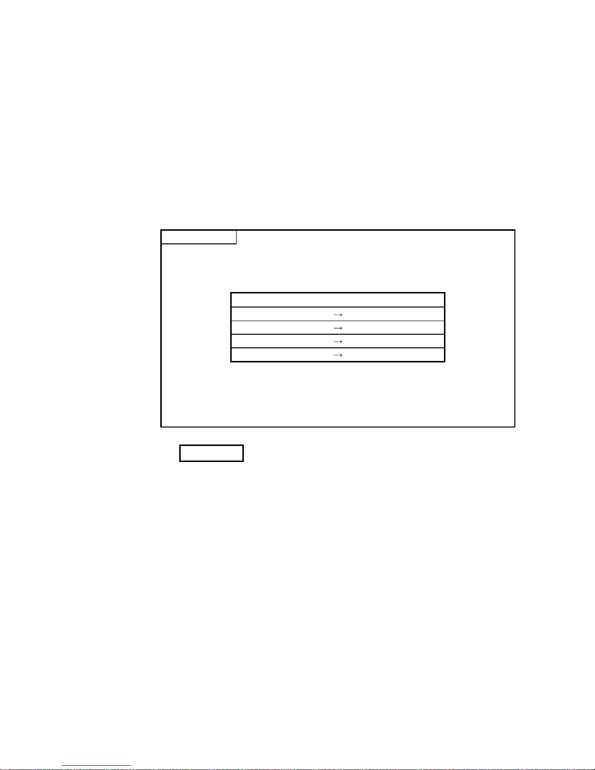
2) For example, multiple first frames and last frames (called user frames) with
the definition shown in the diagram below can be preregistered in the Q
series C24. When sending data to the external device, the data that is
arranged as shown in the diagram below can be sent by designating the
preregistered user frame numbers and arbitrary data. When receiving data
from the external device, by setting the preregistered user frame numbers for
reception at the startup of the Q series C24, the arbitrary data section can be
read to the programmable controller CPU when the message with the
registered content is received.
Arbitrary data
First frame
Last frame
ENQ
Password
Destination
station number
Self-station
number
CR LF
Before sending data, the Q series C24 adds the first frame and last frame
to arbitrary data. When data is received, the arbitrary data section is
stored in the buffer memory as receive data.
3) User frames and various setting values for data communication with the
external device can be preregistered to the Q series C24 flash ROM.
Page 35

1 - 5 1 - 5
1 OVERVIEW
The following table lists which special functions are available for the main data
communication functions of the Q series C24.
Main data communication functions
Special functions
MC
protocol
Non
procedure
protocol
Bidirectional
protocol
Pre-
defined
protocol
Reference
section
Monitoring of the programmable controller CPU using
the programmable controller CPU monitoring function
Chapter 2
Data communication to a remote location using the
modem function
Chapter 3
Reading received data using an interrupt program
Chapter 4
Changing the unit of the data length for communication
data
Chapter 5
Changing the monitoring time for data communication
Chapter 6
Transmission control for data communication
• DC code control (Including Xon/Xoff control)
• DTR/DSR (ER/DR) control
Chapter 7
Data communication using half-duplex communication
Chapter 8
Registration
Chapter 9
Chapter 10
Data communication using user
frames
Transmission,
reception
Chapter 11
Data communication using the transparent code
Chapter 12
Communication using ASCII code data by ASCII-BIN
conversion
Chapter 13
Data communication with multiple external devices using
a multi-drop connection (m:n connection)
Chapter 14
Changing the interface mode after starting data
communication (Changes to communication protocol
and transmission specifications)
Chapter 15
: Available : Not available
Page 36

1 - 6 1 - 6
1 OVERVIEW
1.2 Functions Added/Changed for the QJ71C24N (-R2/R4) and QJ71C24 (-R2)
For the function versions, serial numbers, and software versions of the QJ71C24N
(-R2/R4) or QJ71C24(-R2) with the added or changed functions, refer to the following.
Q Corresponding Serial Communication Module User's Manual (Basic)
Page 37

2 - 1 2 - 1
2 USING THE PROGRAMMABLE CONTROLLER CPU MONITORING FUNCTION
2 USING THE PROGRAMMABLE CONTROLLER CPU MONITORING
FUNCTION
This chapter explains the programmable controller CPU monitoring function with which
the Q series C24 monitors the programmable controller CPU based on the monitoring
information reregistered by the user.
2.1 Overview
The following explains an overview of the programmable controller CPU monitoring
function:
(1) Transmission without using a sequence program
1) The programmable controller CPU monitoring function enables the Q series
C24 to monitor the local station's programmable controller CPU at time
intervals set by the user by reregistering data to be used for the
programmable controller CPU monitoring function.
Data transmission and notification to the external device is possible by
communication using the MC or non procedure protocol without using a sequence
program.
2) The following monitoring information selected by the user can be sent or
notified to the external device as the programmable controller CPU
monitoring results.
Monitoring result
Without the
modem
function
Combined use of the
modem function
(modem communication)
Numeric value stored in
a word device
Local station programmable
controller CPU device (information
on the device to be monitored)
ON/OFF status for a bit
device
Data
transmission
Status of modules of the local station programmable
controller CPU
Notification
Notification message registered in data for connection
(character string data)
3) Two separate timings--constant cycle transmission and condition agreement
transmission--are used to transmit and notify the programmable controller
CPU monitoring results to the external device.
• In the constant cycle transmission, transmission and notification are
performed each time the programmable controller CPU is monitored.
• In the condition agreement transmission, transmission and notification are
performed when the information read from the programmable controller
CPU satisfies the user-defined conditions and an error is detected in the
programmable controller CPU.
(2) Simplifying the device monitoring procedure
When device monitoring is performed by communication using the MC protocol,
the external device must repeatedly perform monitor request transmission and
monitor data reception processing after it executes monitor registration.
By designating the constant cycle transmission for the programmable controller
CPU monitoring function, the device data can be monitored without performing
the monitor request reception processing.
2
Page 38

2 - 2 2 - 2
2 USING THE PROGRAMMABLE CONTROLLER CPU MONITORING FUNCTION
(3) Notification of an error in the programmable controller CPU
In the condition agreement transmission and notification, error information can be
sent to the external device without a sequence program whenever a
programmable controller CPU error occurs.
Monitoring device
information
CPU error
information
External device
Abnormal detection
Q25HCPU
MODE
RUN
ERR.
USER
BAT.
BOOT
RS-232
USB
QJ71C24
CH1.
CH2.
RS-232
CH1.
CH.2
SDA
SG
SDB
RS-422
/485
RDA
RDB
(FG)
(FG)
1
2
5
7
3
4
6
MITSUBISHI
MELSEC
POWER
PULL
Error
occurrence
2
Page 39

2 - 3 2 - 3
2 USING THE PROGRAMMABLE CONTROLLER CPU MONITORING FUNCTION
2.2 About the Programmable Controller CPU Monitoring Function
This section explains the programmable controller CPU monitoring function.
2.2.1 Data registration for using the programmable controller CPU monitoring function
The following explains the data registration by the user to use the programmable
controller CPU monitoring function.
(1) Programmable controller CPU monitor registration for the Q series C24 that is
required to use the programmable controller CPU monitoring function is described
in the following sections. The registration can be performed using one of the
following methods:
1) Registration using the Q series C24 dedicated utility package (GX
Configurator-SC)
2) Registration using the programmable controller CPU monitoring registration
command (0630) for communication with the MC protocol (Detailed
explanation is found in the MELSEC-Q/L MELSEC Communication Protocol
Reference Manual)
3) Registration using the programmable controller CPU "CSET" instruction
(Detailed explanation is found in Chapter 17.)
(2) When this function is used with the modem function and data is transmitted or a
notification message is notified as a programmable controller CPU monitoring
result, register the connection data for the modem function on the "PLC CPU
monitoring system setting" screen of GX Configurator-SC.
(3) By registering the data for using the above programmable controller CPU
monitoring function, the Q series C24 begins monitoring the programmable
controller CPU.
2.2.2 Programmable controller CPU monitoring information
This section explains the monitoring target information used to execute the
programmable controller CPU monitoring function.
(1) The following information can be registered as the target of the programmable
controller CPU monitoring function.
1) Device monitoring for the local station's programmable controller CPU
• Monitoring of the numeric values stored in the word device
• Monitoring of the bit device ON/OFF status
2) Monitoring of the local station's programmable controller CPU status
(2) In monitoring word and bit devices, a maximum total device point value of 960
(equivalent to a maximum of 15360 bits for only bit devices), or a total of 10 blocks
when any continuous device range comprises one block, can be registered.
Since monitoring of the local station's programmable controller CPU status will
also be registered as a one-block portion, up to 11 blocks can be registered.
11 ≥
(Number of word device blocks registered + number of bit device blocks registered)
+ CPU status monitoring (1 block)
960 points ≥
(Total number of all word device block points + total number of all bit device block points)
(1 point = 1 word) (1 point = 16 bits)
(3) With device monitoring of the blocks for which the word and bit devices are
registered, the head device of each block becomes the monitoring target.
Page 40

2 - 4 2 - 4
2 USING THE PROGRAMMABLE CONTROLLER CPU MONITORING FUNCTION
(Example1) For a block in which 10 points of word devices from D100 to D109 are
registered
Monitoring target: Numeric value stored in D100
Data transmitted: Numeric values stored in D100 to D109
(Example2) For a block in which two points of bit devices from M100 to M131 are
registered
Monitoring target: ON/OFF status of M100
Data transmitted: ON/OFF status of M100 to M131
(4) The word and bit devices that can be designated as the monitoring targets and the
device codes that are used to register the monitoring devices are listed in the table
below.
Register the devices using the device ranges existing in the programmable
controller CPU.
Device type Device code
Classification Device
Bit Word ASCII Binary
Device range
(Default)
Special relay
SM 91H
Internal system
Special register
SD A9H
0 to 2047
Input
X
9CH
Output
Y
9DH
0 to 1FFFH
Internal relay
M
90H
Latch relay
L
92H
0 to 8191
Annunciator
F
93H
Edge relay
V
94H
0 to 2047
Link relay
B
A0H 0 to 1FFFH
Data register
D
A8H 0 to 12287
Link register
W
B4H 0 to 1FFFH
Contact
TS C1H
Coil
TC C0H
Timer
Current value
TN C2H
Contact
SS C7H
Coil
SC C6H
Retentive timer
Current value
SN C8H
0 to 2047
Contact
CS C4H
Coil
CC C3H
Counter
Current value
CN C5H
0 to 1023
Link special relay
SB A1H
Link special register
SW B5H
0 to 7FFH
Step relay
S
98H 0 to 8191
Direct input
DX A2H 0 to 1FFFH
Direct output
DY A3H
Internal user
Index register
Z
CCH
0 to 15
R
AFH 0 to 32767
Register File register
ZR B0H 0 to FE7FFH
POINT
(1) Designating a non-existent device code will result in an error.
(2) When the device range in the parameter setting has been changed, the new
device range can be set as the programmable controller CPU's monitoring
target.
Page 41

2 - 5 2 - 5
2 USING THE PROGRAMMABLE CONTROLLER CPU MONITORING FUNCTION
2.2.3 Timing for programmable controller CPU monitoring
The following explains the timing for programmable controller CPU monitoring when
the programmable controller CPU monitoring function is executed.
(1) Programmable controller CPU monitoring using the Q series C24 is performed
continuously at cycle time intervals registered by the user.
(2) Values from 1 to 65535 (unit: 100ms/s/min) can be registered as the cycle time.
Use the following expressions as a reference when registering the cycle time.
(a) When sending device data or the programmable controller
CPU status
Cycle time designation > K + sequence scan time + processing time
+ data transmission time
(b) When notifying through combined use of the modem function
(when notifying)
Cycle time designation > K + sequence scan time + processing time
+ data transmission time
+ data transmission delay time of the modem
+ modem connection and disconnection time
(when sending data)
Cycle time designation > K + sequence scan time + processing time
+ data transmission time
+ data transmission delay time of the modem
+ modem connection and disconnection time
+ circuit disconnection wait time
When modem initialization has not been
performed, the modem initialization time will be
added. (We recommend that the modem
initialization be performed in advance.)
The items that appear in the above expressions are explained below:
• K : 60 ms constant (internal processing time of
the Q series C24)
• Processing time: Processing time for the "Multiple block batch read word
unit command 0406"
For 1 point : 11.3 ms
For 480 points: 23.4 ms
For 960 points: 36.2 ms
• Data transmission time = 1 / transmission rate × bit count for one byte
portion during transmission
× byte count for transmission data
• Bit count for one byte portion during transmission =
1 + data bit count + parity bit + stop bit count
(parity bit = 1, no parity bit = 0)
• Data transmission delay time by the modem: Depends on the modem
specifications, line specifications and line status.
• Modem connection and disconnection time: Depends on the modem
specifications, line specifications and line status.
• Modem initialization time: Depends on the modem specifications.
Page 42

2 - 6 2 - 6
2 USING THE PROGRAMMABLE CONTROLLER CPU MONITORING FUNCTION
(3) To monitor the programmable controller CPU, the Q series C24 reads monitoring
information (device information, programmable controller CPU status information)
from the programmable controller CPU at time intervals set by the user.
POINT
(1) Since the Q series C24 reads the monitoring information (device data,
programmable controller CPU status) at the time of the next programmable
controller CPU END process after the cycle time elapses, make the cycle time
as long as possible.
(2) The following should be considered if the cycle time is short.
• The scan time of the programmable controller CPU is longer and the number
of scan cycles has increased.
• The increase in the processing time of the Q Series C24 programmable
controller CPU monitoring function has increased causing an increase in the
processing time of other data communication functions.
• The load on the external device has increased.
2.2.4 Timings of transmission and notification of monitoring results to the external device
The following explains the timings for the transmission and notification of the
programmable controller CPU monitoring results.
There are two transmission methods for transmitting and notifying the monitoring
results of the local station programmable controller CPU to the external device. These
include constant cycle transmission and condition agreement transmission. One of
these methods must be selected by the user during programmable controller CPU
monitoring registration.
(1) Constant cycle transmission
The monitoring results are transmitted and notified each time monitoring
information is read from the programmable controller CPU.
(Timing to transmit data)
Constant cycle
transmission
Cycle time
Sequence program
External device
END
ENDENDEND
One-block
portion
One-block
portion
Monitoring information
• • •
Page 43

2 - 7 2 - 7
2 USING THE PROGRAMMABLE CONTROLLER CPU MONITORING FUNCTION
(2) Condition agreement transmission
(a) For device monitoring, the monitoring conditions registered by the user
(conditions for sending monitoring results), the monitoring condition values
and the monitoring information read from the programmable controller CPU
are compared. The monitoring results are sent or notified when there is a
block where the monitoring conditions match.
For programmable controller CPU status monitoring, the monitoring results
are sent or notified only once when an error is detected for the first time from
the status information read from the programmable controller CPU. (This
corresponds to the edge triggered transmission noted below.)
(b) Two transmission methods of the monitoring results are available for the
condition agreement transmission for device monitoring. These include edge
triggered transmission and level triggered transmission.
1) Edge triggered transmission
The monitoring conditions registered by the user (conditions for sending
monitoring results), the monitoring condition values and the monitoring
information read from the programmable controller CPU are compared.
The monitoring results are sent or notified only once when an agreement
of the monitoring conditions is detected for the first time. After that, when
the monitoring information read from the programmable controller CPU
does not match the monitoring conditions and then it matches the
monitoring conditions once again, the monitoring results are sent or
notified.
2) Level triggered transmission
The monitoring conditions registered by the user (conditions for sending
monitoring results), the monitoring condition values and the monitoring
information read from the programmable controller CPU are compared.
While the monitoring conditions agree, the monitoring results are sent or
notified at each cycle time.
(Timing to transmit data)
Condition agreement
transmission
Cycle time
Sequence program
(conditions matched/not
matched)
External device
Matched
Not matched
Matched
END
ENDEND
One-block
portion
One-block
portion
Monitoring information
• • •
Page 44

2 - 8 2 - 8
2 USING THE PROGRAMMABLE CONTROLLER CPU MONITORING FUNCTION
(c) In the condition agreement transmission for device monitoring, the head device
for each block is the monitoring target for condition monitoring of each block
device.
For the condition agreement transmission, the monitoring conditions that can be
designated for the device to be registered by the user and the registration values
when designating the monitoring condition are listed in the table below.
Register the monitoring conditions for the head device of each block using
the following table.
Registration value
Valid designated
device
Monitoring condition (item to be judged)
For edge triggered
transmissions
For level triggered
transmissions
Bit Word
Device value or status = device monitoring condition value or status 0001H 0101H
Device value or status ≠ device monitoring condition value or status
0002H 0102H
Monitoring device < monitoring condition value 0003H 0103H
Monitoring device < monitoring condition value 0004H 0104H
Monitoring device > monitoring condition value 0005H 0105H
Unsigned
Monitoring device > monitoring condition value 0006H 0106H
Monitoring device < monitoring condition value 0007H 0107H
Monitoring device < monitoring condition value 0008H 0108H
Monitoring device > monitoring condition value 0009H 0109H
Signed
Monitoring device > monitoring condition value 000AH 010AH
(d) In device monitoring, register the monitoring condition value or status when
the Q series C24 judges that the numeric value/status of the monitoring
device for condition agreement transmission (head device of each block)
agrees with the condition using the registration values listed below.
Type of monitoring device Monitoring condition value or status Registration value
OFF 0000H
Bit device
ON 0001H
Word device Numerical value 0000H to FFFFH
(Example 1) When M0 = ON is the condition agreement
Monitoring condition registration value : 0001H
Registration value for the monitoring condition value or status: 0001H
(Example 2) When D0 > 100 (signed) is the condition agreement
Monitoring condition registration value : 000AH
Registration value for the monitoring condition value or status: 100(64H)
REMARKS
In status monitoring for the programmable controller CPU, the monitoring conditions
and condition values for condition agreement transmission are not registered.
Instead, it is registered as whether or not programmable controller CPU status
monitoring will be performed.
Monitoring results in condition agreement transmission are sent or notified only once
when an error is detected by the status information read from the programmable
controller CPU for the first time.
Page 45

2 - 9 2 - 9
2 USING THE PROGRAMMABLE CONTROLLER CPU MONITORING FUNCTION
2.2.5 Transmission methods of monitoring results and transmission data to the external device
The following explain the method of transmitting the programmable controller CPU
monitoring results and data to the external device.
(1) Data transmission to the external device while performing
communication using the MC protocol
(a) The same format as for the messages sent with the on-demand function is
used to transmit data, except that the on-demand data section is replaced
with the device information and programmable controller CPU status
information. The data is sent as explained in (c) and (d) below.
(Detailed explanation is found in the MELSEC-Q/L MELSEC Communication
Protocol Reference Manual.)
When the interface that is to use the modem function is set in the MC
protocol, connection processing and disconnection processing to the modem
are performed when the programmable controller CPU monitoring results
are transmitted.
(Example) Data transmission by MC protocol with modem function (condition
agreement transmission)
END
ENDEND
External device
Matched
Dial
Disconnection
Cycle time
Sequence program
(conditions matched/
not match)
Not matched
Matched
Registration information
for programmable controller
CPU monitoring
(b) When the transmission of on-demand data using user frames is designated,
the same format as for sending on-demand data using user frames is used
to transmit data, except that the on-demand data section is replaced with the
device information and programmable controller CPU status information.
The data is sent as explained in (c) and (d) below.
See the following explanatory items for data reception by the external
device side.
• Device information, programmable controller CPU status information
arrangement:
MELSEC-Q/L MELSEC Communication Protocol Reference Manual
• Arrangement of data in the user frame section to be sent: Chapter 10
(c) When sending the monitoring results as data during constant cycle
transmission, the entire block portion of the monitoring target device
information and programmable controller CPU status information is
transmitted in batch mode.
Page 46

2 - 10 2 - 10
2 USING THE PROGRAMMABLE CONTROLLER CPU MONITORING FUNCTION
(d) When sending the monitoring results as data during condition agreement
transmission, head data (header) and end data (footer) for the on-demand
function are added to the device information for a block with matched
monitoring conditions and the programmable controller CPU status
information upon the occurrence of an error. The header and footer are
added to each clock, and then the monitoring result data is transmitted.
Transmission is performed in the following order: the programmable
controller CPU status information, then the device information registered
in the word block, and then the device information registered in the bit
block.
POINT
When there is communication using the MC protocol form 1) to 4), all of the device
monitoring head device number will be converted to hexadecimal ASCII data and
sent. (The same conversion is performed during either constant cycle transmission
or condition agreement transmission.)
(2) Data transmission to the external device while performing
communication using the non procedure protocol
(a) The device information and CPU information are sent by the word/byte unit
designations.
When the communication data ASCII-BIN conversion is designated, it is
converted to ASCII code data and sent. (Examples are shown in (f)).
1) When the word/byte unit designation is word unit, the device information
and CPU information are each sent in one-word segments in a (H) (L)
sequence.
2) When the word/byte unit designation is byte, the device information and
CPU information are each sent in one-word segments in a (L) (H)
sequence.
When the interface that is to use the modem function is set in the non
procedure protocol, connection processing and disconnection processing
to the modem are performed when the programmable controller CPU
monitoring results are transmitted.
(Example) Data transmission by non procedure protocol with modem function
(condition agreement transmission)
END
ENDEND
1 block 1 block
Monitoring information
•••
External device
Matched Not matched
Matched
Dial
Disconnection
Cycle time
Sequence program
(conditions matched/
not matched)
(b) When sending monitoring results as data during constant cycle transmission,
the device information of two or more user frame No. and programmable
controller CPU status information that have been currently designated for the
constant cycle transmission by the Q series C24.
Page 47

2 - 11 2 - 11
2 USING THE PROGRAMMABLE CONTROLLER CPU MONITORING FUNCTION
(c) When sending the monitoring results as data during condition agreement
transmission, the device information of two or more user frame No. and
programmable controller CPU status information that have been currently
designated by the Q series C24 for the condition agreement transmission of
the block where the monitoring conditions match are transmitted in batch
mode.
When the monitoring conditions of two or more block match, the device
information and programmable controller CPU status information are
transmitted for each block.
POINT
When there is an ASCII-BIN conversion of communication data using non procedure
protocol, all of the device monitoring head device number will be converted to
hexadecimal ASCII data and sent. (The same conversion is performed during either
constant cycle transmission or condition agreement transmission.)
(d) The user frame numbers that can be designated for data transmission of
programmable controller CPU monitoring results are listed below.
• 1
H to 3E7H (Default registration frame numbers)
• 3E8H to 4AFH (Frame numbers registered by the user in the flash ROM)
• 8001H to 801FH (Frame numbers registered by the user in the buffer memory)
• B001H to B01FH (Dedicated frame numbers for this function listed in (e) below)
For details on how to designate user frame numbers, see Transmission
using user frames in Chapter 11.
(e) For instructing to transmit the device information and programmable
controller CPU status information when sending monitoring results as data,
use the following dedicated user frame numbers.
Valid function
Frame number Information to be tr ansmitted
Constant cycle
transmission
Condition agreement
transmission
B001H Number 1
B002H Number 2
B003H Number 3
B004H Number 4
B005H Number 5
B006H Number 6
B007H Number 7
B008H Number 8
B009H Number 9
B00AH
Device information for the block registered in
number n
Number 10
B061H
Programmable controller CPU status information
(CPU abnormal monitoring data)
B080H Number of blocks sent
B081H Monitoring result information for all blocks
B082H Monitoring result information for blocks satisfying the conditions
Page 48

2 - 12 2 - 12
2 USING THE PROGRAMMABLE CONTROLLER CPU MONITORING FUNCTION
(f) Device information and programmable controller CPU status information are
sent using the data arrangement shown below.
The ASCII-BIN conversion designation is designated in buffer memory
address 121H/1C1H. Note that when the user frame has been designated
by setting to on the value for bit 14, which indicates the user frame No.,
there will be ASCII-BIN conversion of corresponding send data. It will be
sent as binary data. (See Section 13.3.
)
1) When user frame numbers B001H to B00AH are designated (example of
a one-block portion)
• When word device data (W100 to W103, (4 points)) is sent
When the word/byte unit designation is word unit, the device data
will be sent in a (H)
(L) sequence.
The number of registered points is the number of points in word units.
(When ASCII-BIN conversion is not performed)
The total number of bytes for the device data section is the number
of device points
2.
When the word/byte unit designation is byte
When the word/byte unit designation is word
00H01H00HB4H04H00H00H00H01H00H02H00H03H00
H
Monitoring head
device
Device code
Number of
registered points
Device data
LH L HLH
(W)
W100 W101 W1 02 W103
HH H
L
L
L
00H 01H 00H B4H 04H 00H 00H 00H 00H 01H 00H 02H 00H 03H
Monitoring head
device
Device code
Number of
registered points
Device data
LH H LLH
(W)
W100 W101 W1 02 W103
LL LHHH
(When ASCII-BIN conversion is performed)
The total number of bytes for the device data section is the number
of device points
4.
When the word/byte unit designation is byte
57H
Monitoring head
device
Device code
Number of
registered po ints
Device data
LHHLLH HL
30H 30H 30H 30H 30H 30H 30H 30H 30H 30H 30H 30H 30H 31H 30H 30H 30H 33H30H32H30H 30H 30H30H2AH 31H 34H
W
0000
000001
1000200
0
300
0
004
0
W100 W101 W102 W103
LLL
H
HH
When the word/byte unit designations word
57H
Monitoring head
device
Device code
Number of
registered points
Device data
LHLHLH LH
30H 30H 30H 30H 30H 30H 30H 30H 30H 30H 30H 30H 30H 30H 30H 30H 30H 30H30H30H31H 32H 33H30H2AH 31H 34H
W
0000
000001
0010002
0
003
0
004
0
W100 W101 W102 W103
HHHLLL
Page 49

2 - 13 2 - 13
2 USING THE PROGRAMMABLE CONTROLLER CPU MONITORING FUNCTION
• When data for bit device (M16 to M175, (10 point)) is sent
When the word/device unit designation is word unit, the device data
will be sent in a (H)
(L) sequence.
The number of registered points is the number of points in word units.
(When ASCII-BIN conversion is not performed)
The total number of bytes for the device data section is the number of
device points
2.
When the word/byte unit designation is byte
When the word/byte unit designation is word
0100010000000011
3011
Monitoring
head device
Device code
Number of
registered points
Device data
LH LHLH
(M)
10
H00H00H0AH00H
90
H
30H11
H
M
2
3
M
2
9
M
3
0
M
3
1
M
2
2
M
2
1
M
2
8
M
1
6
M
1
7
M
2
0
M
1
9
M
1
8
M
2
7
M
2
5
M
2
6
M
2
4
12H34
H
Device data
LH
0000010010100010
1130
Monitoring
head device
Device code
Number of
registered p oints
Device data
LH HLLH
(M)
10H 00H 00H 0AH 00H90H 11H 30H
M
3
1
M
2
1
M
2
2
M
2
3
M
3
0
M
2
9
M
2
0
M
2
4
M
2
5
M
2
8
M
2
7
M
2
6
M
1
9
M
1
7
M
1
8
M
1
6
34H 12H
Device data
HL
(When ASCII-BIN conversion is performed)
The total number of bytes for the device data section is the number of
device points
4.
When the word/byte unit designation is byte
Monitoring head
device
Device code
Number of
registered points
Device dat a
LHLHLHHL
M
30
H30H30H30H31H30H30H30H41H30H
4DH2A
H
31H31
H
33H30
H
01000 000 101 00010
1
130
M
3
1
M
2
1
M
2
2
M
2
3
M
3
0
M
2
9
M
2
0
M
2
4
M
2
5
M
2
8
M
2
7
M
2
6
M
1
9
M
1
7
M
1
8
M
1
6
0
000
0
001
A
300
1
1
HL
12
4
3
34
H33H
31H32
H
Device dat a
When the word/byte unit designation is word
Monitoring head
device
Device code
Number of
registered points
Device data
LHLHLH
L
H
M
30H 30H 30H 30H 31 H 30H 30H 30H 41H30H4DH 2AH 30H33H31H 31H
01000 100 00000011
3
011
M
2
3
M
2
9
M
3
0
M
3
1
M
2
2
M
2
1
M
2
8
M
1
6
M
1
7
M
2
0
M
1
9
M
1
8
M
2
7
M
2
5
M
2
6
M
2
4
0
0000001A
11003
L
H
3
421
32H31H33H 34H
Device data
Page 50

2 - 14 2 - 14
2 USING THE PROGRAMMABLE CONTROLLER CPU MONITORING FUNCTION
2) When user frame No. B061H is designated
Programmable controller CPU status information (for one block) is sent as the
following data:
when communicating
with ASCII code
when communicating
with binary code
Remarks
Device code "01" 01H
Number of registered points "0001" 0001H
Monitoring head device "000000" 000000H
During normal operation "0000" 0000H
Module warning occurring "0001" 0001H
Device data
Module error/module system error occurring "0002" 0002H
All fixed
value
(When ASCII-BIN conversion is not performed)
The total number of bytes for the device data section is the number of device
points
2.
When the word/byte unit designation is byte
When the word/byte unit designation is word
Monitoring head
device
Device co de
Number of
registered points
Device da ta
LH
L
HLH
01
H00H00H00H
01
H
01
H
00
H
00
H
Monitoring head
device
Device co de
Number of
registered points
Device da ta
HL
L
HLH
01
H00H00H00H
00
H
01
H
01
H
00
H
(When ASCII-BIN conversion is performed)
The total number of bytes for the device data section is the number of device
points
4.
When the word/byte unit designation is byte
When the word/byte unit designation is word
Monitoring head
device
Device code
Number of
registered points
Device data
LHLHLHLH
31
H30H30H
30H30H30H30
H
30
H
30H30H31
H
31
H
30H30H30
H
30
H
1
000
000
000
101
000
Monitoring head
device
Device code
Number of
registered points
Device data
LHLHLHLH
31
H30H30H
30H30H30H30
H
31
H
30H30H30
H
31
H
30H30H30
H
30
H
1
000
000
000
100
010
3) When user frame No. B080
H is designated
The transmission block count will be sent as follows:
(Example)
Number of registered word blocks: 2 (D0 to D3 (4 points), W100 to W107 (8 points))
Number of registered bit blocks : 1 (M0 to M31 (2 points))
(When ASCII-BIN conversion is not performed) (When ASCII-BIN conversion is performed)
Number of registered bit blocks
Number of registered word blocks
CPU abnormal monitoring
01H02H00
H
Number of registered
word blocks
LH
32H30H30
H
30H30H31
H
201000
LHLH
Number of registered
bit blocks
CPU abnormal
monitoring
Page 51

2 - 15 2 - 15
2 USING THE PROGRAMMABLE CONTROLLER CPU MONITORING FUNCTION
4) When user frame No. B081H is designated
Information on monitoring results for all blocks are sent as follows:
Results are sent in the following order: the device information registered in the
word block, the device information registered in the bit block and then
programmable controller CPU status information.
(Example)
Number of registered word blocks: 1 (W100 to W103 (4 points))
Number of registered bit blocks : 1 (M0 to M15 (1 point))
Perform CPU status monitoring : 1 (1 point)
(When ASCII-BIN conversion is not performed)
The total number of bytes for the device data section is the number of device
points
2.
When the word/byte unit designation is byte
01
H
Monitoring head
device
Device code
Number of
registered points
Device data
LH L HLH
00
H
00
H
00H00
H
00
H
00H00
H
00
H
B4H04
H
01
H
02
H
03
H
Monitoring head
device
Device code
Number of
registered points
Device data
LH LHLH
(M)
00
H00H00H
01H00
H
90
H
30
H
11
H
0100010000000011
3011
M
0
7
M
1
3
M
1
4
M
1
5
M
0
6
M
0
5
M
1
2
M
0
0
M
0
1
M
0
4
M
0
3
M
0
2
M
1
1
M
0
9
M
1
0
M
0
8
00
H
Monitoring head
device
Device code
Number of
registered points
Device data
LH LHLH
00
H
00
H
00H00
H
00
H
01H01
H
(W)
W100 W101 W102 W103
LLLHHH
When the word/byte unit designation is word
Number of
registered points
L
01
H
Monitoring head
device
Device code
Number of
registered points
Device data
LH H LLH
00
H
00
H
00H00
H
00
H
01H02
H
03
H
B4H04
H
00
H
00
H
00
H
Monitoring head
device
Device code
Number of
registered points
Device data
LH HLLH
(M)
00H00H00
H
01H00
H
90
H
11
H
30
H
0000010000100010
1130
M
1
5
M
0
5
M
0
6
M
0
7
M
1
4
M
1
3
M
0
4
M
0
8
M
0
9
M
1
2
M
1
1
M
1
0
M
0
3
M
0
1
M
0
2
M
0
0
00
H
Monitoring head
device
Device code
Device data
LH HLH
00
H
00
H
00H00
H
00
H
01H01
H
(W)
W100 W101 W102 W103
HHHLLL
Page 52

2 - 16 2 - 16
2 USING THE PROGRAMMABLE CONTROLLER CPU MONITORING FUNCTION
(When ASCII-BIN conversion is performed)
The total number of bytes for the device data section is the number of device
points
4.
When the word/byte unit designation is byte
H
57H 31H
Monitor ing
head device
Device code
Number of
register ed points
Device dat a
LHLHLH HL
0000000 0 000 010 020 03010 4 0 0 0
30H 30H 30H 30H 30H 30H 30H 30H 30H 30H 30H 30H 30H 31H 30H 30H 30H 33H30H32H30H 30H 30H30H2AH 31H 34H
W
Monitoring
head device
Device code
Number of
registered points
Device data
LHLHLHL
0000 000010
M
30H 30H 30H 30H 30H 30H 30H 30H 31H30H4DH 2AH
3011
31H33H 30H
01000 000 10100010
1
130
M
1
5
M
0
5
M
0
8
M
0
7
M
1
4
M
1
3
M
0
4
M
0
8
M
0
9
M
1
2
M
1
1
M
1
0
M
0
3
M
0
1
M
0
2
M
0
0
Monitoring head
device
Device code
Number of
registered points
Device data
LHLHLHL
0000000 0 00000 1
30H30H30H30H30H30H30H30H30H30H30H30
H
30H31
H
30
H
31
H
0
1
HL HL H L
W100
W101 W102
W103
H
When the word/byte unit designation is word
57H 30H
Monitoring
head device
Device cod e
Number of
registered points
Device dat a
LHLHLH LH
0000000 0 000 000 000 00010 4 1 2 3
30H 30H 30H 30H 30H 30H 30H 30H 30H 30H 30H 30H 30H 30H 30H 30H 30H 30H30H30H31H 32H 33H30H2AH 31H 34H
W
Monitoring
head device
Device code
Number of
registered points
Device data
LHLHLH
L
H
0000 000010
M
30H 30H 30H 30H 30H 30H 30H 30H 31H30H4DH 2AH
1130
33H31H 31H
01000 100 00000011
3
011
M
0
7
M
1
3
M
1
4
M
1
5
M
0
6
M
0
5
M
1
2
M
0
0
M
0
1
M
0
4
M
0
3
M
0
2
M
1
1
M
0
9
M
1
0
M
0
8
Monitoring head
device
Device code
Number of
registered points
Device data
LHLHLHH
0000000 0 00000 1
30H30H30H30H30H30H30H30H30H30H30H30
H
30H31
H
30
H
31
H
0
1
LH LH LH
W100
W101 W102
W103
L
Page 53

2 - 17 2 - 17
2 USING THE PROGRAMMABLE CONTROLLER CPU MONITORING FUNCTION
5) When user frame No. B082H is designated
Information on the monitoring results for the condition agreement blocks are sent
for each block.
Results are sent in the following order: The programmable controller CPU
status information, the device information registered in the word block and then
the device information registered in the bit block.
(Example)
Number of registered word blocks: 2 (D0 to D3 (4 points), W100 to W103 (4 points))
Number of registered bit blocks : 1 (M0 to M15 (1 point))
When the condition satisfied monitoring device is W100 = 0 and M0
≠ ON
(When ASCII-BIN conversion is not performed)
The total number of bytes the device data section is the number of device points
2.
When the word/byte unit designation is byte
For W100 to W103 block data For M0 to M15 block data
01
H
Monitoring head
device
Device code
Number of
registered points
Device data
LH L HLH
(W)
00
H
00
H
00H00
H
00
H
00
H
00
H
00
H
B4H04
H
01
H
02
H
03
H
Monitoring head
device
Device code
Number of
registered points
Device data
LH LHLH
00
H00H00H
01H00
H
90
H
30H11
H
0100010000000011
3011
M
0
7
M
1
3
M
1
4
M
1
5
M
0
6
M
0
5
M
1
2
M
0
0
M
0
1
M
0
4
M
0
3
M
0
2
M
1
1
M
0
9
M
1
0
M
0
8
(M)
HL HL H L
W100 W101
W102
W103
When the word/byte unit designation is word
For W100 to W103 block data For M0 to M15 block data
01
H
Monitoring head
device
Device code
Number of
registered points
Device data
LH H LLH
(W)
00
H
00
H
00H00
H
00
H
01
H
02
H
03
H
B4H04
H
00
H
00
H
00
H
Monitoring head
device
Device code
Number of
registered points
Device data
LH HLLH
00H00H00
H
01H00
H
90
H
11H30
H
0000010010100010
1130
M
1
5
M
0
5
M
0
6
M
0
7
M
1
4
M
1
3
M
0
4
M
0
8
M
0
9
M
1
2
M
1
1
M
1
0
M
0
3
M
0
1
M
0
2
M
0
0
(M)
LH LH L H
W100 W101 W102 W103
Page 54

2 - 18 2 - 18
2 USING THE PROGRAMMABLE CONTROLLER CPU MONITORING FUNCTION
(When ASCII-BIN conversion is performed)
The total number of bytes for the device data section is the number of device
points
4.
When the word/byte unit designation is byte
For W100 to W103 block data For M0 to M15 block data
Monitoring head
device
Device code
Number of
register ed points
Device data
LHLHLHL
0000000 0 000 010 020 03010 4 0 0
30H30H30H30H30H30H30H30H30H30H30H30H30H31H30H30
H
30H33
H
30H32
H
30
H
30
H
30H30
H
57H2A
H
31
H
34
H
W
H
0
Monitoring head
device
Device code
Number of
registered points
Device data
L
HLHLH
H
L
0000 000010
M
30H 30H 30H 30H 30H 30H 31H30H4DH 2AH
3011
31H31H33H 30H
01000 000 1
0100010
1
130
M
1
5
M
0
5
M
0
6
M
0
7
M
1
4
M
1
3
M
0
4
M
0
8
M
0
9
M
1
2
M
1
1
M
1
0
M
0
3
M
0
1
M
0
2
M
0
0
30H 30H
W100 W101 W102 W103
LLL
HHH
When the word/byte unit designation is word
For W100 to W103 block data For M0 to M15 block data
Monitoring head
device
Device code
Number of
register ed points
Device data
LHLHLHH
0000000 0 000 000 000 00010 4 1 2
30H30H30H30H30H30H30H30H30H30H30H30H30H30H30H30
H
30H30
H
30H30
H
31
H
32
H
33H30
H
57H2A
H
31
H
34
H
W
L
3
Monitoring head
device
Device code
Number of
registered points
Device data
L
HLHLH
L
H
0000 000010
M
30H 30H 30H 30H 30H 30H 30H 30H 31H30H4DH 2AH
1130
31H31H33H 30H
01000 000 1
0100010
3
011
M
0
7
M
1
3
M
1
4
M
1
5
M
0
6
M
0
5
M
1
2
M
0
0
M
0
1
M
0
4
M
0
3
M
0
2
M
1
1
M
0
9
M
1
0
M
0
8
W100 W101 W102 W103
HHH
LLL
Page 55

2 - 19 2 - 19
2 USING THE PROGRAMMABLE CONTROLLER CPU MONITORING FUNCTION
(3) Notification to the interface side using the modem function
(a) The notification message (text string data) contained in the user registered
data for connecting the modem function is conveyed using the modem
function.
The device information and the CPU status information read from the
programmable controller CPU are not sent to the external device in the
notification message. Include the device information and the CPU status
information by which the programmable controller CPU status can be
checked in the preregistered notification message.
(b) The method for message notification is functionally the same as the
notification using the modem function described in Chapter 3.
The difference is that notification is performed with Y14 OFF when using the
modem, whereas for notification using programmable controller CPU
monitoring, notification is performed for whenever the programmable
controller CPU error is detected or the designated device status is matched
with the monitoring conditions (see Section 2.2.4).
(c) During constant-cycle transmission, a notification message for one
connection data registered for notifying constant-cycle transmission is sent.
(d) During condition agreement transmission, a notification message for
connection data registered in the block where the monitoring conditions
match is sent in block units.
When there are multiple blocks where the monitoring conditions match,
notification is performed at the "Wait time of notification" interval (notification
interval) set by the user for use with the modem function. The programmable
controller CPU monitoring stops until notification has been performed to all
blocks where the monitoring conditions match.
POINT
(1) When performing message notification using the programmable controller CPU
monitoring function, set the corresponding interface side as the target of the
modem function.
(2) When setting data for the programmable controller CPU monitoring function
with GX Configurator-SC, programmable controller CPU monitoring begins
immediately when the Q series C24 starts up.
Page 56

2 - 20 2 - 20
2 USING THE PROGRAMMABLE CONTROLLER CPU MONITORING FUNCTION
2.2.6 Execution sequence for using the programmable controller CPU monitoring function
The following explains the execution sequence for using the programmable controller
CPU monitoring function.
(1) When transmitting the monitoring results through data transmission/notification
messages using the modem function, perform the following settings in order to
use the modem function.
Setting item Explanation section
Initial setting using the GX Configurator-SC Section 3.4.2
Registration of data No. for initialization and data No. for connection Sections 3.4.3 and 3.4.4
Initialization of the Q series C24 modem/TA Section 3.4.5
(2) Register programmable controller CPU monitoring for the Q series C24 using one
of the methods described in Section 2.2.1.
(3) By registering programmable controller CPU monitoring, the Q series C24
monitors the local station's programmable controller
CPU regardless of the
RUN/STOP status and sends the monitoring information to the external device.
(4) When reregistering programmable controller CPU monitoring in order to change
the registration data for the programmable controller CPU monitoring, reregister
after canceling the programmable controller CPU monitoring.
1) When registering with communication using the MC protocol (Detailed
explanation is found in the MELSEC-Q/L MELSEC Communication Protocol
Reference Manual.)
2) When registering with the programmable controller
CPU's "CSET" instruction
(Detailed explanation is found in Chapter 17.)
To cancel when using GX Configurator-SC, change the programmable
controller CPU to the STOP status, redo the settings, and then restart the
QCPU.
Page 57

2 - 21 2 - 21
2 USING THE PROGRAMMABLE CONTROLLER CPU MONITORING FUNCTION
2.3 Settings for Using the Programmable Controller CPU Monitoring Function
This section describes system settings required for constant cycle transmission and
condition agreement transmission.
2.3.1 System setting items for the programmable controller CPU monitoring function
The following explains system setting items for the programmable controller CPU
monitoring function.
POINT
(1) Register transmission user frames by GX Configurator-SC, after checking the
specifications and setting methods explained in Chapters 9 to 11 of this
manual.
(2) Register connection data for the modem function by GX Configurator-SC, after
checking the specifications described in Section 3.4.4 of this manual.
(1) Setting items and requirement when performing communication
using the MC protocol
Constant cycle transmission
Condition agreement
transmission
Setting item
Data
transmission
Notification
(
1)
Data
transmission
Notification
(
1)
Reference section
Cycle time units (3) (a) of this section
Cycle time (3) (b) of this section
PLC CPU monitoring functi on (1H: Constant cycle) (2H: Condition agreement) (3) (c) of this section
PLC CPU monitoring transmission measure (Data) (Notification) (Data) (Notification) (3) (d ) of this section
Constant cycle transmission Transmission pointer
Output count
(4) of this section
Section 11.4.2
Data No. for connection
Section 2.2.5 (3)
Section 3.4.4
Number of registered word blocks
Number of registered bit blocks
(3) (e) of this secti on
PLC CPU abnormal monitoring (3) (f) of this secti on
No. n block monitoring device Monitoring device
Head device No.
Read point
(3) (g) of this secti on
Condition agreement transmission
Monitoring condition
(3) (h) of this secti on
Monitoring condition value
(3) (i) of this section
Transmission pointer
Output count
(4) of this section
Section 11.4.2
Data No. for connection
Section 2.2.5 (3)
Section 3.4.4
PLC CPU abnorm al monitoring designat ion
Condition agreem ent transmission
Transmission pointer
Output count
(4) of this section
Section 11.4.2
Data No. for connection
Section 2.2.5 (3)
Section 3.4.4
: Setting required : Setting not re quired
1 Cannot be used for the LJ71C24(-R2).
POINT
While using the notification function, the device information and the CPU status
information cannot be transmitted.
Page 58

2 - 22 2 - 22
2 USING THE PROGRAMMABLE CONTROLLER CPU MONITORING FUNCTION
(2) Setting items and requirement when performing communication
using the non procedure protocol
Constant cycle transmission
Condition agreement
transmission
Setting item
Data
transmission
Notification
Data
transmission
Notification
Reference section
Cycle time units (3) (a) of this section
Cycle time (3) (b) of this section
PLC CPU monitoring functi on (1H: Constant cycle) (2H: Condition agreement) (3) (c) of this section
PLC CPU monitoring transmission measure (Data) (Notification) (Data) (Notification) (3) (d ) of this section
Constant cycle transmission Transmission pointer
Output count
(4) of this section
Section 11.4.2
Data No. for connection
Section 2.2.5 (3)
Section 3.4.4
Number of registered word blocks
Number of registered bit blocks
(3) (e) of this secti on
PLC CPU abnormal monitoring (3) (f) of this secti on
No. n block monitoring device Monitoring device
Head device No.
Read point
(3) (g) of this secti on
Condition agreement transmission
Monitoring condition
(3) (h) of this secti on
Monitoring condition value
(3) (i) of this section
Transmission pointer
Output count
(4) of this section
Section 11.4.2
Data No. for connection
Section 2.2.5 (3)
Section 3.4.4
PLC CPU abnorm al monitoring designat ion
Condition agreement transmission
Transmission pointer
Output count
(4) of this section
Section 11.4.2
Data No. for connection
Section 2.2.5 (3)
Section 3.4.4
: Setting required : Setting not re quired
POINT
While using the notification function, the device information and the CPU status
information cannot be transmitted.
Page 59

2 - 23 2 - 23
2 USING THE PROGRAMMABLE CONTROLLER CPU MONITORING FUNCTION
(3) Contents of setting items
The data items to be set using GX Configurator-SC to use the programmable
controller CPU monitoring function and the setting contents are explained below.
(a) Cycle time units
• Designates the unit for "(b) cycle time" below for reading information from
the programmable controller CPU using the programmable controller CPU
monitoring function.
• The cycle time units and the cycle time designated using this unit can also
be used as the transmission time interval for constant cycle
communication.
(b) Cycle time
Designates the time for one cycle when reading information from the
programmable controller CPU in order to perform programmable controller
CPU monitoring.
(c) Programmable controller CPU monitoring function
Designates the timing (constant cycle transmission or condition agreement
transmission) when sending/notifying information on the programmable
controller CPU monitoring results (device information/CPU status
information) to the external device.
• The time interval designated in data items (a) and (b) above for reading
information from the programmable controller CPU can also be used as
the transmission time interval for constant cycle communication.
• The conditions for condition agreement transmission are designated using
data items (h) and (i) below.
(d) Programmable controller CPU monitoring transmission measure
Designates the means by which the programmable controller CPU
monitoring results are conveyed to the external device.
• Data transmission
The device information and the programmable controller CPU status
information are sent as the monitoring results.
• Notification
Notification message is sent as the monitoring results.
(e) Number of registered word blocks, number of registered bit blocks
Designates the number of word device blocks (number of registered word
blocks) and the number of bit device blocks (number of registered bit blocks)
registered in the Q series C24 as the target when performing device data
monitoring or transmission.
(f) CPU abnormal monitoring
Designates whether or not the Q series C24 monitors abnormality of the
local station programmable controller CPU (status monitoring) in the
programmable controller CPU monitoring.
Page 60

2 - 24 2 - 24
2 USING THE PROGRAMMABLE CONTROLLER CPU MONITORING FUNCTION
(g) Monitoring device, head device No., read point (Number of registered points)
When performing device data monitoring or transmission, designate the
device range for each block for the number of blocks designated by setting
item (e), number of registered word blocks and number of registered bit
blocks.
The target of device data monitoring for condition agreement
transmission is the head device for each block.
Word device designated block: Head word device (for one word)
Bit device designated block : Head bit device (for one bit)
1) The monitored device is the item that indicates the target device of the
corresponding block and designated with the codes listed in Section
2.2.2 (4).
2) The head device is the data that designates the head of the target
device range for the corresponding block.
3) The read point is the item that indicates the target device range for the
corresponding block which designate points from the head device No..
The bit device designates points in word units (1 point = 16 bits)
4) The methods for designating these data are the same as the designation
methods used when reading from or writing to the device memory, which
are described in the MELSEC-Q/L MELSEC Communication Protocol
Reference Manual.
REMARKS
When the user performs the programmable controller CPU monitoring registration,
the device will designate either a decimal or hexadecimal device No.. The read
points (registration points) are designated as hexadecimal. However, if this is done
by either MC protocol communication (form 1) to 4)) or non procedure protocol
communication, when ASCII-BIN conversion of the communication data has been
designated, the head device No. for all devices to be sent to external devices as the
monitoring results will be converted to hexadecimal ASCII data and sent.
(h) Monitoring condition
When condition agreement transmission is designated with the
programmable controller CPU monitoring function (c), designate the
conditions for transmitting information for the monitoring condition value (i).
(i) Monitoring condition value
When condition agreement transmission is designated with the
programmable controller CPU monitoring function (c), this item designates
the status/numeric value of the monitoring condition (h).
• When the monitoring device is a word device: Designate the monitoring
condition value with a numeric value
• When the monitoring device is a bit device : Designate the monitoring
condition with a numeric
value (1/0) corresponding to
ON/OFF.
Page 61

2 - 25 2 - 25
2 USING THE PROGRAMMABLE CONTROLLER CPU MONITORING FUNCTION
(4) Setting items for sending monitoring results
The following is an example of setting items and data transmission when sending
the monitoring results of the programmable controller CPU monitoring function
execution to the external device using the non procedure protocol.
(Example)
This example shows a case in which the D0 to D3 device information and user
frame data are sent by the edge trigger method using a condition of D0 = 0.
Perform the settings on the "PLC CPU monitoring system setting" screen and
the "###" screen of GX Configurator-SC.
1) PLC CPU monitoring system setting
Setting item Set data Remarks
Cycle time units min
Cycle time 3
PLC CPU monitoring function Condition agreement
PLC CPU monitoring transmission measure Data transmission
Number of registered word blocks 1
Number of registered bit blocks 0
PLC CPU abnormal monitoring 0
No. 1 block monitoring device Monitoring device D
Head device No. 0
Read point 4
Condition agreement transmission
Monitoring condition
Edge =
Monitoring condition value 0
Transmission pointer 49
Output count 3
Settings other than
those listed at left
are not required
2) Setting the transmission user frames
User frame number
User frame number
User frame number (03H)
User frame number
User frame number
User frame number
User frame number
Transmission frame No. designation 50th
Transmission frame No. designation 51st
Transmission frame No. designation 55th
Transmission frame No. designation 54th
Transmission frame No. designation 53rd
Transmission frame No. designation 52nd
Transmission frame No. designation 56th
Transmission frame No. designation 57th
Transmission frame No. designation 46t h
Transmission frame No. designation 49th
Transmission frame No. designation 48th
Transmission frame No. designation 47th
User frame number (02H)
User frame number
User frame number
User frame number
User frame number (B001
H
)
Set the first block (from D0 to D3)
Set the user frame data (ETX)
Set the user frame data (STX)
E
T
X
Device
data
(D0)
Device
data
(D1)
Device
data
(D2)
Device
data
(D3)
External device
Data sent when the condition D = 0 is satisfied
Number of
registered
points
Device code
Monitoring
head
device
E
T
X
Page 62

2 - 26 2 - 26
2 USING THE PROGRAMMABLE CONTROLLER CPU MONITORING FUNCTION
2.3.2 How to register and cancel the programmable controller CPU monitoring function
The following describes the method for registering and canceling the programmable
controller CPU monitoring function from the programmable controller CPU.
POINT
(1) For details on the method for registering and canceling the programmable
controller CPU monitoring function with GX Configurator-SC, refer to the Q
Corresponding Serial Communication Module User's Manual (Basic).
(2) For details on the method for registering or canceling the programmable
controller CPU monitoring with a command of MC protocol, refer to the
MELSEC-Q/L MELSEC Communication Protocol Reference Manual.
(When registering or canceling from the programmable controller CPU)
For details on the CSET command, see Section 17.3.
Create control code data from D0
ZP.CSET
"Un"
Processing for abnormal completion
Processing for normal completion
M1
M1M0
M0
D200
D0
K1
Registering
programmable controller
CPU monitoring
Scan Scan Scan
END
processing
END
processing
END
processing
At abnormal completion
Instruction execution
Setting processing
Sequence program
Completion device
Completion device +1
P
rogrammable controller
CPU
CSET instruction
1) Stores the data for programmable controller CPU monitoring registration in the
device that designates the control data for the CSET instruction.
2) Executes the CSET instruction.
At the end of the scan in which the CSET instruction was completed, the
completion device (M0) designated by (D2) turns ON and then turns OFF at the
next END processing.
3) When there is an error, (D2) + 1 turns ON and the error code in stored in the
completion status (S2) + 1.
Page 63

2 - 27 2 - 27
2 USING THE PROGRAMMABLE CONTROLLER CPU MONITORING FUNCTION
(a) Example of a program for performing programmable controller CPU
monitoring registration
This example shows a program that registers programmable controller CPU
monitoring for the CH1 side interface.
This registration is for transmitting the contents of M0 to M15 and D100 to
D109 to the external device using constant cycle transmission (cycle time
is 3 min).
Converts registration command to pulses
Sets execution type
Sets request type (programmable controller CPU monitoring registration)
Sets cycle time unit to minutes
Sets cycle time to 3 (min)
Sets the monitoring function to constant cycle transmission
Sets the means of transmission to data transmission
Sets data set complete flag -1
Sets the number of registered word blocks to 1
Registers the devices for D100 to D109 as the first block
Registers the devices for M0 to M15 as the second block
Sets data setting complete flag -2
Executes programmable controller CPU monitoring registration
Normal completion
Abnormal completion
Sets the number of registered bit blocks to 1
Sets the o utput he ad pointer
Sets the transmission count of the user frame
(b) Example of a program for executing programmable controller CPU
monitoring cancellation
This example shows a program that cancels programmable controller CPU
monitoring for the CH1 side interface.
Sets pulse command
Executes pr ogrammabl e control ler CPU moni toring re gistratio n rese
t
Normal completion
Abnormal completion
Page 64

2 - 28 2 - 28
2 USING THE PROGRAMMABLE CONTROLLER CPU MONITORING FUNCTION
2.4 Precautionary Notes for Using the Programmable Controller CPU Monitoring Function
(1) The cycle time will be affected by the following factors.
Keep these in mind when setting the cycle time.
1) When the programmable controller CPU is accessed by a module other than
the Q series C24.
2) When a data communication function other than the programmable controller
CPU monitoring function is used.
3) When transmission stops by DTR/DSR control.
(2) Both the constant cycle transmission and the condition agreement transmission
cannot be designated together for the same interface.
(3) Only the local station's programmable controller CPU can be the target for the
programmable controller CPU monitoring function.
(4) A new programmable controller CPU monitoring registration cannot be performed
while the programmable controller CPU monitoring function is in operation. In this
case,
1) Perform the new programmable controller CPU monitoring registration after
canceling the programmable controller CPU monitoring.
2) If the new programmable controller CPU monitoring registration is performed
without canceling the programmable controller CPU monitoring, an error will
occur.
Also, for programmable controller CPU monitoring registration using GX
Configurator-SC, perform the registration after placing the programmable
controller CPU in the STOP status, and then restart QCPU.
(5) While the programmable controller CPU monitoring function is in operation, even if
an error occurs with transmission/notification of the programmable controller CPU
monitoring results or reading of data from the programmable controller CPU, the
programmable controller CPU monitoring function operation will not stop.
(6) The programmable controller CPU monitoring function can only be used when the
system configuration is 1:1.
Page 65

2 - 29 2 - 29
2 USING THE PROGRAMMABLE CONTROLLER CPU MONITORING FUNCTION
(7) The following describes how the Q series C24 operates when the programmable
controller CPU monitoring result information cannot be sent to the external device
due to line disconnection or other reasons.
Even if an error occurs while the programmable controller CPU monitoring
function is in operation, the ERR LED does not light up. (This is the same as
when using the on-demand function of the MC protocol.)
(a) When the setting for the transmission monitoring time designation (timer 2) is
an infinite wait (0H)
1) Reading of monitoring data from the programmable controller CPU stops
until the transmission of monitoring data completes.
2) When transmission resumes, reading of monitoring data from the
programmable controller CPU resumes and monitoring data and
information are transmitted.
(b) When the setting for the transmission monitoring time designation (timer 2) is
other than an infinite wait (0
H)
1) A transmission timeout error occurs, monitoring information read from the
programmable controller CPU, and transmission of monitoring information
resumes.
2) The error code is stored in the programmable controller CPU monitoring
function error code storage area (address: 2205
H).
(8) When device data for the programmable controller CPU cannot be read because
of a programmable controller CPU error (hardware failure, etc.), the error code is
stored in the programmable controller CPU monitoring function error code storage
area and the Q series C24 performs the monitoring processing based on
previously read data.
(9) When the monitoring information is transmitted as data using the modem function,
a modem connection error will occur if a modem connection is requested for the
following reasons.
• A connection request by Y11
• A notification-issued request by Y14
If possible, provide a dedicated Q series C24 for using the programmable
controller CPU monitoring function.
When using both the programmable controller CPU monitoring function and data
communication function with a single Q series C24 and one of the above modem
connection errors occurs, re-execute a connection request in consideration of the
transmission timing set by the user for the programmable controller CPU
monitoring function.
Page 66

3 - 1 3 - 1
3 COMMUNICATIONS BY THE MODEM FUNCTION
3 COMMUNICATIONS BY THE MODEM FUNCTION
This chapter explains the overview and how to use the modem function, which can be
used for data communication with remote external devices and paging pager terminals.
3.1 Overview
The overview of the modem function is described below:
(1) The modem function easily performs data transmission/reception to remote
devices via public lines/office telephone systems/digital lines (ISDN) by connecting
a modem or TA (terminal adapter) to the Q series C24's RS-232 interface.
1) Communicating arbitrary data with an external device
2) Call pager receiver (beeper) to notify the programmable controller system
maintenance information.
(2) Initialization of the modem or TA, line connection (dialing), and line disconnection
are performed using the programmable controller CPU.
(3) Once the line is connected, data communication with the external device via public
line/office telephone system/digital line, or a call to pager receiver can be made.
Modem/TA ( 1)
Pager receiver
RS-232
Q series C24
1 TA: terminal adapter
External device
Modem/TA ( 1)
3
Page 67

3 - 2 3 - 2
3 COMMUNICATIONS BY THE MODEM FUNCTION
3.1.1 Features
The following explains the features of the modem function.
(1) Interface that can use the modem function
1) The modem function can be used with the Q series C24 using an RS-232
interface.
2) For the QJ71C24(N)-R2 and LJ71C24-R2, the modem function can be used
for only one of the two RS-232 interfaces.
Through the other interface of the Q series C24, direct data communication
with an external device can be performed using MC protocol, non procedure
protocol or bidirectional protocol (independent operation).
QJ71C24-R2
CH1. CH2.
CH1.
CH2.
Communication using the modem function
Communication without using the modem function
(2) Initialization, line connection and disconnection of the modem or TA
1) The following set values for line connection can be used by storing to the Q
series C24 Flash ROM in multiple sets.
• Modem/TA initialization data (AT command)
User setup: 30 sets (78 bytes/set); default value: 13 sets
• Connection data
User setup: 30 sets (80 bytes/set)
(Telephone number of the connection destination and display message to
the pager receiver.)
2) By registering the above data to the Q series C24 ahead of time, the
modem/TA (terminal adapter) initialization, line connection (dialing), and line
disconnection can be performed with ease.
3) When the no-communication interval time (1 min to 120 min) is set, the Q
series C24 disconnects the line when a no-communication condition has
occurred for the set period of time following the line connection.
(3) Communication between a remote external device and
programmable controller CPU
1) Data communication can be performed via full-duplex communication.
2) From the external device to the programmable controller CPU,
communication using the MC protocol, non procedure protocol and
bidirectional protocol can be performed.
3) From the programmable controller CPU to the external device,
communication using the MC protocol (transmission by the on-demand
dedicated-protocol function only), the non procedure protocol and bidirectional
protocol can be performed.
3
Page 68

3 - 3 3 - 3
3 COMMUNICATIONS BY THE MODEM FUNCTION
(4) Notification to the pager receiver
1) In order to notify to the pager receiver of the programmable controller system
maintenance information, the Q series C24 performs calling and message
transmission according to the user-designated connection data when the
output signal from programmable controller CPU is turned from ON to OFF.
2) Because Q series C24 notification processing is performed while the output
signals from programmable controller CPU are turned OFF from ON,
dedicated notification can be performed when the programmable controller
CPU enters the STOP state due to an error, etc.
Modem
Notification
1
n
Out of material
detection
Notification-issued
request Y14
Notification execution
direction
Data number for
connection
0
0
QJ71C24-R2
CH1. CH2.
CH1.
CH2.
MODE
RUN
ERR.
USER
BAT.
BOOT
RS-232
USB
Q25HCPU
(5) Communication from GX Developer
1) Access from GX Developer to the remote programmable controller CPU can
be made. (read and write from/to the device data and sequence program)
2) The QCPU can be accessed after reconnection from the Q Series C24 side
using the callback function.
QJ71C24-R
CH1. CH2.
CH1.
CH2.
Q25HCPU
MODE
RUN
ERR.
USER
BAT.
BOOT
RS-232
USB
Modem
Modem
GX Developer
Public line
RS-232
cable
RS-232
cable
Transmission costs after line connection by callback from the Q Series C24
side are borne by the Q Series C24 side.
Page 69

3 - 4 3 - 4
3 COMMUNICATIONS BY THE MODEM FUNCTION
(6) Remote password check
If the remote password check has been set for the Q series C24 installed in the
QCPU, the Q series C24 executes a remote password check when the
programmable controller is accessed from an external device using the Q series
C24 modem function.
The following is an overview of the QCPU remote password function. See
Section 3.3.3 for more details.
(a) Remote password function
The remote password function allows / prohibits access to the QCPU from
an external device via the following modules.
• Q series C24
• Ethernet module
• Built-in CPU of Ethernet port
In the case of the Ethernet module, the remote password function can be
used for data communications connections with an external device. For
details, see the User's Manual (Basic) for the Ethernet module.
(b) Station where the remote password and remote password check are set
1) In the case of a programmable controller system with one QCPU station
External device
access source
Modem
Public line
Modem
Communication executing the
remote password check
• Communication using MC protocol
• Communication using the GX Develope
r
GX Developer parameter setting
• Remote password
• Module subject to the remote
password check
QCPU
Q series C24
Remote
password
Remote
password
check
2) In the case of a programmable controller system consisted of multiple
QCPU stations
Set in the QCPU station which is the entrance of the programmable
controller system as viewed from the external device (the local station
QCPU in the diagram below).
Ethernet
module
QCPU
Ethernet
External device
access source
QCPU
(Access
station)
Modem
Public line
Modem
Q series C24
(Relay
station)
Ethernet
Ethernet
module
(Local station)
Remote
password
Remote
password
check
QCPU
Network System 1
Set in the local station to allow/prohibit access to
the network System 1 from the external device.
Not set in the relay station or access station. ( )
Ethernet
module
Ethernet
module
When set in a station other than the QCPU which is the entrance of
the programmable controller system (relay station or access station in
the above diagram), access to other stations beyond the set station is
prohibited.
Page 70

3 - 5 3 - 5
3 COMMUNICATIONS BY THE MODEM FUNCTION
3.1.2 Function list
The following lists the overview of the modem function:
Function Overview
Modem/TA initialization
Initializes the modem/TA using the user-designated initialization data (AT command). (Auto
initialization of the modem / TA is possible.)
Line connection (dialing)
Dials the partner telephone number according to the user-designated connection data and
enables data communication after establishing the line connection. When the modem/TA is not
initialized, performs initialization.
Performs communication with an external device using the MC
protocol, non procedure protocol or bidirectional protocol.
Performs communication with the partner Q series C24-installed
station by modem/TA connection using non procedure protocol or
bidirectional protocol. (Station-to-station communication)
Data communication
Enables the communication between GX Developer and
programmable controller via Q series C24.
Notification Calls and transmits messages to the pager receiver.
Communication method:
full-duplex communication
Synchronization method:
start-stop synchronous
system (asynchronous)
Line disconnection Forcefully disconnects the line from the connected destination device.
Flash ROM reading,
writing (registration) and
deletion
Reads, writes (registers) and deletes the initialization data (AT command) and data for
connection from/to the Flash ROM in the Q series C24 according to the request from
programmable controller CPU.
Remote password check
Allows the Q series C24 to execute the remote password check set in the QCPU when there is
communication from the external device to the Q series C24 using MC protocol or the
programmable controller is accessed using GX Developer.
Callback
After line connection from GX Developer, access to the QCPU from GX Developer is made
possible through line reconnection from the Q Series C24 (callback). Transmission costs after
line connection from the Q Series C24 side are borne by the Q Series C24 side.
Page 71

3 - 6 3 - 6
3 COMMUNICATIONS BY THE MODEM FUNCTION
3.1.3 Comparisons with related devices
The following lists the comparison with the related products which supports data
communication with the programmable controller using the modem and public line, etc.,
similarly to the communication performed via the modem function.
QJ71C24N(-R2/R4),
QJ71C24(-R2)
(function version)
Communication function name
B A
QC24N
(modem function)
Q6TEL
(for QnACPU/ACPU)
A6TEL
(for ACPU)
Sequence program
Modem/TA initialization
GX Configurator-SC
(
1
)
— —
Line connection (dialing) (Performed on the external device side)
MC protocol
Non procedure protocol
Communication between
same products (such as
C24-C24)
Bidirectional protocol
Communication between Q series C24 and other
products
— — —
Remote communication from GX Developer
Callback function
Remote communication from peripheral device for
GPPQ
Remote communication from peripheral device for
GPPA
Notification Pager receiver
Remote password check (
2
)
Line disconnection (Performed on the external device side)
Sequence program
GX Developer
GPPQ
GPPA
Data setting
• Data for modem
initialization
• Data for connection
GX Configurator-SC
— — —
Number of connectable modems/TAs 1
Transmission type Pulse/tone
Analog 2-line method
Analog 4-line method
Connectable lines
Digital line (ISDN)
: enable
: disable
1 Modem initialization is executed automatically when the Q Series C24 starts up.
2 Prior to data communication, the Q series C24 checks whether the remote password specified by the user
and the remote password set in the QCPU agree or not. If they agree, it allows access to the specified
station.
Page 72

3 - 7 3 - 7
3 COMMUNICATIONS BY THE MODEM FUNCTION
3.2 System Configuration
This section describes system configurations when the modem function is used to call a
pager receiver or to perform data communication with an external device via public lines.
3.2.1 System configuration when performing data communication with an external device
The following describes the system configuration examples used when performing
data communication between the external device and programmable controller using
the Q series C24's MC protocol/non procedure protocol/bidirectional protocol.
(1) Connection example with an external device
QJ71C24-R2
CH1.
CH2.
CH1.
CH2.
Q25HCPU
MODE
RUN
ERR.
USER
BAT.
BOOT
RS-232
USB
RS-232
cable
Modem
Modem
RS-232
cable
External device
Public line
(2) Connection example with a Q series C24
QJ71C2 4-R2
CH1.
CH2.
CH1.
CH2.
MODE
RUN
ERR.
USER
BAT.
BOOT
RS-232
USB
Q25HCPU
QJ71C24-R2
CH1. CH2.
CH1.
CH2.
MODE
RUN
ERR.
USER
BAT.
BOOT
RS-232
USB
Q25HCPU
Modem
RS-232
cable
RS-232
cable
Public line
Modem
(3) Connection example with a Q series C24 via cellular phone
QJ71C24-R2
CH1.
CH2.
CH1.
CH2.
MODE
RUN
ERR.
USER
BAT.
BOOT
RS-232
USB
Q25HCPU
QJ71C24-R2
CH1.
CH2.
CH1.
CH2.
MODE
RUN
ERR.
USER
BAT.
BOOT
RS-232
USB
Q25HCPU
Modem
RS-232
cable
Public line
Cellular
Phone
Cellular phone
connection adapter
The public lines indicated in (1) to (3) above are compatible with the office
telephone system as well.
In the system configurations shown in (1) and (2) above, the digital line (ISDN)
can replace the public line.
When connecting via a digital line, a TA (terminal adapter) and a DSU (digital
service module) are used instead of a modem.
Page 73

3 - 8 3 - 8
3 COMMUNICATIONS BY THE MODEM FUNCTION
3.2.2 System configuration when using the notification function
The following describes the system configuration example when calling the pager
receiver by the notification function.
QJ71C24-R2
CH1. CH2.
CH1.
CH2.
MODE
RUN
ERR.
USER
BAT.
BOOT
RS-232
USB
Q25HCPU
Modem
RS-232
cable
Public line
Pager receiver
The public line indicated above is compatible with the office telephone system
as well.
Page 74

3 - 9 3 - 9
3 COMMUNICATIONS BY THE MODEM FUNCTION
3.2.3 System configuration when connecting GX Developer
The following describes the system configuration when GX Developer performs data
communication with a remote station programmable controller via Q series C24.
QJ71C24-R2
CH1. CH2.
CH1.
CH2.
MODE
RUN
ERR.
USER
BAT.
BOOT
RS-232
USB
Q25HCPU
Modem
Modem
RS-232
cable
RS-232
cable
Public line
GX Developer
The above public line is compatible with the office telephone system as well.
Set items as below for "Transfer Setup" screen using GX Developer.
PC side I/F : Serial
PLC side I/F : C24
Telephone line connection (Q/A6TEL, C24) : Data for line connection
Set the other items corresponding to the access destination station.
For how to display the "Transfer Setup" screen, refer to manuals for GX
Developer.
POINT
When the GX Developer is connected, perform the settings and operations
described in Section 3.3.7 to prevent a line to the modem from disconnecting even
if communication between the GX Developer and programmable controller is
interrupted.
Page 75

3 - 10 3 - 10
3 COMMUNICATIONS BY THE MODEM FUNCTION
3.2.4 Precautions for system configurations
The following describes the precautionary items when configuring the system to
perform data communication with an external device or call a pager receiver via public
line, an office telephone system or digital line (ISDN) using the Q series C24 modem
function.
(1) Usable Q series C24 interface
1) The modem function can be used for the RS-232 interface only.
2) For the QJ71C24(N)-R2 and LJ71C24-R2, the modem function can only be
used for only one of the two RS-232 interfaces.
3) Interactive data communication via two interface of Q series C24 (linked
operation) is not possible.
(2) Connectable modem/TA
Only the modems/TA indicated in Section 3.3.2 can be used for the Q series C24
RS-232 interface using the modem function.
(3) Number of connectable modems/TA's
Only one modem/TA can be connected to the Q series C24 RS-232 interface that
uses the modem function.
(4) Modem/TA connection cables
1) The RS-232 cable supplied with the modem/TA or the designated modem/TA
cable can be used for connection between the Q series C24 and modem/TA.
2) For the RS-232 interface of the Q series C24, a D-sub 9-pin connector
(female) is used.
For the connection cable of the Q series C24 side, refer to the User's Manual
(Basic).
(5) Modem/TA installation
1) Install the modem/TA according to the modem/TA manual.
When installed in an area in which a lot of noises exists, malfunctions may
occur.
2) In order to prevent the effects of noise and power surges, do not connect
near or tie the cable together with a main circuit line, high-voltage line or load
line other than for the programmable controller with the modem/TA
connection cable.
Page 76

3 - 11 3 - 11
3 COMMUNICATIONS BY THE MODEM FUNCTION
(6) Connectable lines
1) The connections can be made with the following lines.
Perform connection tests beforehand and confirm that connection is possible.
• Public line or office telephone system of analog two-line method
• Digital line (ISDN)
2) It is not possible to connect to call-waiting lines, in order to avoid data errors
or automatic line disconnection due to the call-waiting interrupt tone.
3) Avoid connections with party-line telephones to avoid interrupted calls during
communication.
4) If an alert sound is sent at fixed intervals from the communication machine to
prevent long-term calls, data may experience errors.
It is recommended to check the normality/abnormality of data reception
between devices, and perform transmission-retry processing when an
abnormality is detected.
5) See the modem/TA manual regarding the connection from a modem to public
line/office telephone system, or from a TA (terminal adapter) to a digital line.
(7) Communication system
Communication via the modem function is performed using full-duplex
communication.
Connections cannot be made devices designed for half-duplex communication.
(8) Data communication and notification to external devices
1) Data communication with external devices and notification to a pager receiver
are performed using the public line or electric wave transmitted from the
electric wave transmission base.
There might occur a condition in which correct data communication or
notification cannot be carried out due to an error from the system's setup
environment, electric-wave transmission status, error in the partner device,
etc.
Perform a connection test beforehand, and confirm that connection is
possible.
2) In notification processing via electric-wave transmission, errors from the
pager receiver cannot be detected.
Setup a separate call circuit with a lamp display or buzzer to ensure the
safety of the programmable controller system.
Page 77

3 - 12 3 - 12
3 COMMUNICATIONS BY THE MODEM FUNCTION
3.3 Specifications
This section explains the transmission specification on the Q series C24 side,
connectable modems/TA's (terminal adapter), I/O signals related to the modem
function, and buffer memory for the usage of the modem function.
3.3.1 Transmission specifications
The transmission specifications on the Q series C24 side for use of the modem
function are as listed below.
The transmission specifications between Q series C24 and a modem/TA (local station
Q series C24) that are not provided in this table are listed in the User’s Manual (Basic).
Item
QJ71C24N
QJ71C24
LJ71C24
QJ71C24N-R2
QJ71C24-R2
LJ71C24-R2
QJ71C24N-R4
Modem function Available Not available
Interface that can use the modem function RS-232
Linked operation between CH1 and CH2 of the Q
series C24
Not available
Communication method Full duplex communication
Synchronization method Asynchronous method
Transmission speed
1
1200, 2400, 4800, 9600, 14400, 19200, 28800,
38400, 57600, 115200 (bps)
Start bit 1
Data bit 7 / 8
Parity bit 1 (On) / 0 (Off)
Data format
Stop bit 1 / 2
Parity check On (odd/even selectable) / Off
Error detection
Sum check code On / Off
Transmission control RS · CS control / not-control (selectable)
No procedure protocol Available
Bidirectional protocol Available
MC protocol Available
Data communication
Pre-defined protocol Not available
Line connection (Q series C24: modem) 1:1
—
1 When the first five digits of the serial No. are 03042 or earlier, the transmission
speed cannot be set to 115200 bps for connection between the Q series C24 and
GX Developer via a modem.
Page 78

3 - 13 3 - 13
3 COMMUNICATIONS BY THE MODEM FUNCTION
3.3.2 Specification of connectable modems/TAs (terminal adapters)
The following table lists the specification of modems/TAs that can be connected to the
Q series C24 side when the modem function is used.
(1) Specification and precautions for the connectable modems
(a) Modem specification
Specification
Item
When using the subscriber's telephone
line/office telephone system
When using a manual line
connection/cellular phone
Remarks
Connection line Analog 2-line —
Initialization Hayes AT command compatible See Section 3.4.3
Telephone line A line compatible with NTT communication protocol
See Section 3.2.4 regarding
the restrictions
ITU-T V. 34/V.32bis/V.32/V. 22bis/V. 22/V. 21/V. fc Communication
standard
Bell 212A/103
MNP Class 4 and 10 compliant Error correction
(
1)
ITU-T V.42 compliant
MNP Class 5 compliant Data compression
(
1)
ITU-T V.42bis compliant
Modem-tomodem
communication
specification
ANS-ORG mode switch — Mode switching required
—
Q series C24-side connector
(RS-232)
9-pin (female) D sub User's Manual (B asic)
DR signal control Only the DR (DSR) signal must be able to turn on ( 2)
Q series C24-to
modem
communication
specification
Other Compatible with the Q series C24 specification
See Section 3.3.1, User's
Manual (Basic)
1 The following are the functions of the modem itself that become available by
issuing the AT commands to the modem. See the modem manual for details.
(1) Error correction
1) When a noise occurs on the line, scrambled data may appear due
to interrupted communication data.
The error correction function is intended to suppress effects from
such noises.
2) If an error such as scrambled data is detected by the error
correction, the modem retries the transmission.
When the number of retries has exceeded the modem's limit, the
modem determines that communication cannot be performed in that
environment and disconnects the line.
3) Both modems must support the MNP4 or V.42 protocol.
(2) Data compression
1) This function compresses data to be sent prior to transmission, and
inflates the compressed data upon reception, then forwards to the
terminal.
2) The data compression is effective for the execution speed at a
maximum of 200 % for the MNP5 and 300 % for the V.42bis.
3) Both modems must support the MNP5 or V.42bis protocol.
(3) Flow control (RS · CS control)
When communication between a modem and terminal is faster than
between two modems, the flow control is performed in the following order:
Page 79

3 - 14 3 - 14
3 COMMUNICATIONS BY THE MODEM FUNCTION
1) The modem transmits data to the partner by storing the data from
the terminal in the modem buffer.
2) When the buffer in the modem becomes almost full, the modem
outputs a data-transmission temporary stop request (CS (CTS)
signal = OFF) to the terminal.
The terminal then stops data transmission to the modem when the
data-transmission temporary stop request (CS (CTS) signal =
OFF) is received.
Even while the terminal pauses data transmission, the modem
continues to send data to the partner.
3) When a free space is present in the modem buffer, the modem
outputs the data-transmission resume request (CS (CTS) signal =
ON) to the terminal.
The terminal then resumes data transmission to the modem when the
data-transmission resume request (CS (CTS) signal = ON) is
received.
2 Modems that turn on the CD (DCD) signal simultaneously cannot be
used.
(b) Precautions for selecting a modem
1) When using a cellular phone
A modem with the error correction function of MNP class-10 is
recommended. However, note that communication may not be
established depending on the line condition.
2) Modem setting
• Set the modem on the Q series C24 side as shown below:
Setting item Setting range
Communication rate Depends on the modem i n use ( 1)
Modem command Hayes AT command
SI/SO control None
Communication method No procedure
Data bit
Stop bit
Data format
Parity bit
Match the Q series C24 ( 2) ( 3)
1 When using different modems, the slower communication rate will
be in effect.
2 Some modems may transmit one character as 10 bits.
Check the modem specifications when setting the Q series C24
transmission specifications.
3 Some modems may switch the communication rate following the
start of data communication.
Since the Q series C24 cannot switch the communication rate, set
the modem side so that its communication rate does not switch.
• When using a modem whose DR terminal (signal) is set by a switch, set
the DR-terminal (modem output) switch level to high.
When using a modem requiring DR terminal setting with software, write
the command that turns on the DR (DSR) signal into the data for
initialization.
Set the "Modem initialization time DR signal valid/invalid designation"
to "Invalid" during modem function system settings with GX
Configurator-SC.
Page 80

3 - 15 3 - 15
3 COMMUNICATIONS BY THE MODEM FUNCTION
(2) Specification and precautions for the connectable TA's (terminal
adapters)
(a) TA specification
Item Specification Remarks
Connection line
ISDN (INS net 64) equivalent
High-speed digital dedicated line
DSU and TA are required
Initialization Hayes AT command compatible See Section 3.4.3
Communication standard
B-channel line exchange (V.110)
D-channel packet exchange
TA-to-TA
communication
specification
Electrical condition V.28 compliant
Circuit definition V.24 compliant
—
Q series C24-side connector
(RS-232)
9-pin (female) D sub
User's Manual (Basic)
DR signal control Only the DR (DSR) signal must be able to turn on
(
1
)
Q series C24-to-
TA
communication
specification
Other Compatible with the Q series C24 specification
See Section 3.3.1, User's
Manual (Basic)
1 TA's that turn on the CD (DCD) signal simultaneously cannot be used.
Use a TA capable of flow control as described in (1) (a) in this section
also for the communication between the TA and terminal.
control is a function of the TA itself that becomes available by issuing
the AT commands to the modem. See the TA manual for details.
(b) Precautions for selecting a TA
1) Set the TA on the Q series C24 side as listed below:
Setting item Setting range
Communication rate Depends on the TA in use
TA command Hayes AT command
SI/SO control None
Communication method No procedure
Data bit
Stop bit
Data format
Parity bit
Match the Q series C24 (
1
) (2)
1 Some TAs may transmit one character as 10 bits.
Check the TA specifications when setting the Q series C24
transmission specifications.
2 Some TAs may switch the communication rate following the start of
data communication.
Since the Q series C24 cannot switch the communication rate, set
the TA side so that its communication rate does not switch.
2) When using a TA whose DR terminal (signal) is set by a switch, set the
DR-terminal (TA output) switch level to high.
When using a TA requiring DR terminal setting with software, write the
command that turns on the DR (DSR) signal into the data for initialization.
Set the "Modem initialization time DR signal valid/invalid designation" to
"Invalid" during modem function system settings with GX ConfiguratorSC.
Page 81

3 - 16 3 - 16
3 COMMUNICATIONS BY THE MODEM FUNCTION
3.3.3 Compatibility with the QCPU remote password function
This section explains the Q series C24 data communication for the QCPU remote
password function.
Refer to Section 3.1.1 for an overview of the Q series C24 check function for the
QCPU remote password.
The remote password function is a function that has been added to the QCPU as a means of preventing
improper access (such as destroying a program or data) from an external device. However, this function
cannot completely prevent improper access.
The user should incorporate his/her own safeguards when it is necessary to protect the security of the
programmable controller system from improper access from an external device.
The company cannot assume any responsibility for any problems that may arise from system troubles
caused by improper access.
An example of a safeguard on the programmable controller CPU with respect to improper access
One example is shown in Section 3.3.6, in which the programmable controller CPU disconnects a line to
the external device when the number of times a "remote password mismatch" is detected exceeds the
number set by the user with regard to the Q series C24 remote password check explained in this section.
(1) Data communication during remote password setting
This section explains the use and setting of the QCPU remote password function
and data communication between the external device and the QCPU when a
remote password has been set.
(a) Allowing/prohibiting access to the programmable controller from the external
device
1) Access allow processing (unlock processing)
• To access the specified QCPU, the external device performs the
remote password unlock processing with respect to the Q series C24
(
) of the directly connected station (local station) after line connection
for the modem function.
• If the unlock processing has not been performed, the remote password
check performed by the Q series C24 ( ) that has received a
communication request prohibits access to the specified station. (See
(2) in this section.)
• All data communication before the unlock processing is performed will
be processed as an error.
The Q series C24 of the QCPU station for which a remote password is
set will be indicated.
2) Access processing
Normal completion of the remote password unlock processing allows the
specified station to be accessed.
• Perform communication using MC protocol.
(Perform on-line operation when GX Developer is connected.)
3) Access prohibition processing (lock processing)
• When the specified station access is completed, the process for
disconnecting the line for the modem function is performed in order to
disable further access.
• When line disconnection is completed, the remote password lock
processing is performed automatically.
Page 82

3 - 17 3 - 17
3 COMMUNICATIONS BY THE MODEM FUNCTION
3 Even if the Ethernet module that transmits a communication
request to other Ethernet is set as a module subject to
the remote password check, unlock and lock processing
is not necessary.
Ethernet
module
Remote password
check
(When accessing other station QCPU)
Remote password
check
QCPU
Q series C24
(When accessing the local station QCPU)
A station
( 1)
1 Unlock and lock processing for the local station
remote password is possible.
Remote password unlock and lock processing for
the relay station and access station cannot be performed
( 3)
QCPU
QCPU
Ethernet
Ethernet
(Local station)
(Relay station)
(Access station)
Remote password
Remote
password
2) Access
Modem
1) Unlock processing
3) Lock processing ( 2)
Modem
2 Lock processing is performed when a line for the modem
function is disconnected.
A station
( 1)
ModemModem
QCPU
Q series C24
(Local station)
Ethernet
module
Ethernet
module
2) Access
Ethernet
module
3) Lock processing ( 2)
1) Unlock processing
POINT
(1) The remote password unlock and lock processing can be performed only for
the Q series C24 of the local station directly connected to the external device.
The remote password unlock and lock processing cannot be performed for the
Ethernet module of the other stations (relay station and access station).
(2) The remote password unlock processing from the external device is performed
using dedicated commands for MC protocol communication.
(3) See Section 3.3.7 (8) for what to do when the remote password unlock
processing is completed abnormally.
Page 83

3 - 18 3 - 18
3 COMMUNICATIONS BY THE MODEM FUNCTION
(2) Remote password check processing performed by the Q series
C24
(a) Communication in which a remote password check is performed
1) When the following parameters are set for the Q series C24 installed in
the QCPU station, the Q series C24 performs a remote password check
for communication requests listed below.
• When a remote password is set in the QCPU
• When the Q series C24 that is communicating data with the external
device has been set as a module subject to the remote password
check
2) The Q series C24 performs a remote password check with respect to a
communication request to the local station/other station received from
the external device.
3) The Q series C24 does not perform a remote password check for the
following communication requests.
• Transmission request from the local station QCPU (such as
transmission using non procedure protocol)
• Communication request from the external device (including GX
Developer connected to the local station QCPU) transmitted to other
station upon request from the QCPU
QCPU
Path for items subject
to remote password check
Path for items not subject
to remote password check
GX Developer
Remote password
check
Remote password
check
QCPU
2)
1)
3)
(Local station)
(Other station)
3)
Ethernet module
Remote password
Remote
password
ModemModem
( 1)
Q series
C24
Ethernet module
1 In the above diagram, a communication request from the external device cannot
be received since the remote password check setting has been executed.
If the remote password check setting has not been executed, a communication
request can be received and data communication from the external device is
possible.
(b) Selecting modules subject to the remote password check
The user can select any Q series C24 to perform the remote password
check and set this using QCPU parameters.
(This is set on the GX Developer remote password setting screen.)
Page 84

3 - 19 3 - 19
3 COMMUNICATIONS BY THE MODEM FUNCTION
(c) Stations that can be accessed when the remote password check is
performed
1) If the external device performs the remote password unlock processing
with respect to the Q series C24 of the directly connected station (local
station) after line connection for the modem function, it can access the
local station QCPU.
2) When accessing the programmable controller of another station via the
Ethernet module of a relay station or access station, the following
settings determine whether access is allowed/prohibited.
• To prohibit access to other station from an external device using the
CC-Link IE Controller Network, MELSECNET/H or MELSECNET/10
relay communication function of the Ethernet module, place a check
mark at the following setting items in the remote password setting for
the relay station or access station.
"GX Developer communication port (UDP/IP) (
), dedicated
commands, CC IE Control, MNET/10(H) relay communication port"
Set on the GX Developer remote password setting screen.
If a check mark is not placed at the above setting items, access to
other station will be allowed.
3) See the user's manual (Basic) for the Ethernet module for stations that
can be accessed when accessing other station programmable
controllers via the Ethernet module. (When reading the manual,
substitute the Q series C24 with the station connected to the external
device).
(3) Data communication procedure
This section explains the procedure when the external device performs data
communication via the Q series C24 in which the remote password check is
performed.
1) Initialization of the modem of the Q series C24 side and external device side
is performed at each device sides.
2) The line is connected from the external device.
3) The external device performs the remote password unlock (release)
processing for the QCPU of the station where the Q series C24 is installed
using dedicated commands for MC protocol communication. (The unlock
processing cannot be performed for the QCPU of other station.)
See Section 3.3.7 (8) for what to do when the remote password unlock
processing is completed abnormally.
4) Data communication is performed from the external device using MC protocol.
5) When data communication using MC protocol is completed, a line for the
modem is disconnected from the external device.
When line disconnection is completed, the remote password lock processing
is performed automatically.
REMARKS
(1) Refer to the MELSEC-Q/L MELSEC Communication Protocol Reference
Manual for the unlock processing command for the remote password.
(2) When accessing the programmable controller from GX Developer connected to
the Q series C24, the remote password unlock processing is performed when
on-line operation begins.
Page 85

3 - 20 3 - 20
3 COMMUNICATIONS BY THE MODEM FUNCTION
(4) How to set the remote password
On the screen below for setting parameters (remote password) using GX
Developer, set the remote password in the QCPU and specify the Q series C24
that performs the check.
Set the remote password as the following instructions.
[Start procedure]
"GX Developer"
Remote password "Remote password setting" screen
[Setting screen]
[Setting item]
Item name Set data Setting range/choices
Password settings
Enter the remote password to be set in the QCPU (
1
)
4 bytes
Model name
Select the type of module that checks the remote
password set in the QCPU
QJ71C24/CMO
Start XY
Set the head address of the module that checks the
remote password
0000
H to 0FE0H
Password active
module settings
Conditions (No setting required)
—
1 Consider the following when setting the remote password.
• Avoid using a character string of simple numbers or letters only.
• Mix numbers, letters and special characters (?, ., !, &, %, etc.).
• Avoid using a character string that represents the user's name or
date of birth.
POINT
(1) When using the Q series C24 in a multiple CPU system, write the remote
password setting in the control CPU of the Q series C24.
(2) After setting the remote password in the QCPU, reboot the QCPU (CPU No. 1 in
a multiple CPU system). (Reset/power reset using the RESET/L.CLR switch)
By rebooting the QCPU, the remote password becomes valid.
(3) The password supported by the QCPU function version A is used to prohibit
reading/writing of file data in the QCPU using GX Developer.
Dual access control can be provided by using the remote password described
in this section and password for file access.
Page 86

3 - 21 3 - 21
3 COMMUNICATIONS BY THE MODEM FUNCTION
(5) Setting from GX Configurator-SC
When the Q series C24 performs a remote password check for the remote
password set in the QCPU, the remote password check setting as well as the
present check results can be monitored with respect to the screen items listed in
the table below.
See Section 3.3.6 for an explanation of each area.
GX Configurator-SC
setting/monitor screen
Setting/monitor items for the remote password check Buffer memory address
Remote password mismatch notification count designation 8204 (200CH) "Modem function system
setting" screen
Remote password mismatch notification accumulated count designation 8205 (200DH)
Remote password mismatch notification count designation 8204 (200CH)
Remote password mismatch notification accumulated count designation 8205 (200DH)
Accumulated count of unlock process normal completion 8955 (22FBH)
Accumulated count of unlock process abnormal completion 8956 (22FCH)
"Modem function monitor/test"
screen
Accumulated count of lock process based on circuit disconnection 8959 (22FFH)
Page 87

3 - 22 3 - 22
3 COMMUNICATIONS BY THE MODEM FUNCTION
3.3.4 Compatibility with the callback function
The following describes the Q Series C24 callback function that can be used when
accessing the QCPU from GX Developer connected to the Q Series C24.
(1) About the Callback function
(a) What is the Callback function
The callback function is a function that makes it possible to access the
QCPU from GX Developer by reconnection (callback) of the line from the Q
Series C24. Transmission costs after line connection from the Q Series
C24 side are borne by the Q Series C24 side.
(b) Settings in order to use the callback function
The callback function can be used by setting it through GX Configurator-SC,
then registering it in the Q Series C24. (See (4) in this section.)
(c) Selecting the callback destination GX Developer
GX Developer that can be called back in accordance with the settings in the
Q Series C24 can be selected as described below.
1) If callback destination GX Developer is fixed (1 module)
(Callback connection (during fixed))
Connection can be made to only fixed GX Developer (1 module)
registered in the Q Series C24.
2) If it is being made possible to change callback destination GX
Developer (Callback connection (during designated number))
It is possible to connect to GX Developer when the callback
destination telephone number (Call number) is specified.
3) If the maximum number of callback destination GX Developer is limited
to 10 modules.
(Callback connection (during max. designated number is 10))
Connection is possible with only those pieces of GX Developer (max.
10 modules) with a callback destination telephone No. registered in the
Q Series C24.
A description of the callback operation in 1) to 3) is shown in (4) (b).
Modem
GX Developer
Modem
1) Line Connection
2) Temporary line disconnection
3) Line connection
4) Access to the QCPU
Setting of callback function
designation settings by the
GX Configurator-SC
Selection of the
connection system
and line connections
5) Line disconnection
Q Series C24
Processing by the callback function
Processing for the GX Developer
to access the QCPU
Page 88

3 - 23 3 - 23
3 COMMUNICATIONS BY THE MODEM FUNCTION
(2) Data communications procedure
Here, the procedure for data communications when using the callback function is
shown.
(a) Q series C24 side procedure
Carry out procedure of starting the modem function and data
communications in accordance with Section 3.4.1.
1) Set the callback function by GX Configurator-SC. (See (4) in this
section.)
2) Initialize the Q Series C24 side modem. (See Section 3.4.)
3) The modem’s initialization completed signal (X10) goes On when
modem initialization is completed.
Wait for the line connection from GX Developer.
Select the connection system (connect way) from GX Developer,
then make line connection.
When the Q Series C24 callback processing is completed normally,
the line connection signal (X12) is in the ON state.
POINT
See the GX Developer's Operating Manual for details of the line connection screen
from the GX Developer when using the callback function.
(3) Cautions during data communications
(a) Set the GX Developer side modem which the Q Series C24 is to reconnect
to (callback) on "with Auto Reception". (With Auto Reception: This setting
enables line connection from the external device.)
(b) When a request is issued for a line connection from another GX Developer
during a temporary line disconnection from the GX Developer side by
callback processing, the Q Series C24 executes a callback operation for the
latter connection request.
The Q Series C24 terminates callback processing to GX Developer that it
received a connection request from earlier.
(c) If you are making a line connection to the GX Developer by the following
connection system, select "callback reception waiting" as the connection
system for GX Developer that the Q Series C24 is reconnecting to
(callback) and make the connection.
• Callback request (during fixed/during designated number)
(Example) In the case of line connections with "Callback request (during
designated number)" as the connection system.
Modem
Modem
Callback request
(during designated number)
GX Developer
Telephone No. 1)
Modem
Setting of callback function
designation settings by the
GX Configurator-SC
Select "Callback request (during designation number)",
input the telephone No. 2) and make the line connection.
Callback data No. 1 Telephone No. 1)
Callback data No. 2
Callback data No. 3
Callback data No. 10
Telephone No. 2)
Telephone No. 3)
Telephone No. 10)
Registration in the Q Series C24
Line connection
Select "Callback reception waiting"
and make the line connection.
"Callback
reception waiting"
GX Developer
Telephone No. 2)
to to
Page 89

3 - 24 3 - 24
3 COMMUNICATIONS BY THE MODEM FUNCTION
(d) If callback processing was not executed normally, an error message screen
is displayed on the GX Developer side. Perform the processing operation
(reconnection operation, etc.) corresponding to the displayed message.
The operating state on the Q Series C24 side can be confirmed by the
following items in the GX Configurator-SC monitor/test screen.
GX Configurator-SC
Monitor / test screen
Monitor item
Buffer memory
address
Description
X10: Modem initialization completion —
X•Y monitor/test
X12: Connection in progress —
Section 3.3.5
Modem function
monitor/test
Modem function sequence status 222
H Section 3.3.6
(e) Set the settings related to the callback function in the following areas of GX
Developer.
[Starting Procedure]
GX Developer
[Tools] [Options] TEL
1) Line callback cancel wait time
(Setting range: 1 to 180 s. (Default: 90 s.))
This specifies the waiting time after sending a response to a callback
request from the Q Series C24, until the line is disconnected from GX
Developer.
If the line is not disconnected from GX Developer within the specified
time in this area, the Q Series C24 forcibly disconnects the line,
terminating callback processing.
2) Callback delay time
(Setting range: 1 to 999 s. (Default: 20 s.))
This specifies the time from the temporary line disconnect on the GX
Developer side until the Q Series C24 reconnects (callback).
POINT
Refer to the troubleshooting section of the Q Corresponding Serial Communication
Module User's Manual (Basic) for the symptoms, causes, and actions of problems
that may occur during access from GX Developer to the QCPU when using the
callback function.
Page 90

3 - 25 3 - 25
3 COMMUNICATIONS BY THE MODEM FUNCTION
(4) Setting and monitoring by GX Configurator-SC for use of the
callback function
(a) Setting, monitoring / test items
Carry out setting, monitoring and testing of the callback function using the
following GX Configurator-SC screen.
1) Setting items through the "Modem function system setting" screen
This shows the callback function setting items.
See Section 3.3.6 for the modem function setting items, including the
following items.
Setting Item Setting value
Setting
possible /
impossible
Description
GX Developer connection designation Connect
Be sure so specify “Connect” when using
the callback func tion.
Callback function designation
Settings 1 to 6 (See (4)
(b) in this section.)
Select according to the callback operati on.
Callback denial notification
accumulated count designation
0 to 65535
Specify the accumulated count value
informed to the user.
Data No. for Callback designation 1 to
10
BB8H to 801FH
Specify the connection data No. See
Section 3.4.4 for setting values.
: Must be set : Set as necessary
2) Monitoring / Testing through the "modem function monitor / test" screen
This shows the callback function monitoring and testing.
See Section 3.3.6 for monitoring and testing of the modem function,
including the following items.
Callback function monitoring / test items Buffer memory address
Callback permit accumulated count 8944 (22F0H)
Callback denial accumulated count 8945 (22F1H)
Auto (callback) connection permit accum ulated count 8946 (22F2H)
Auto (callback) connection denial accumulated count 8947 (22F3H)
Accumulated count of callback receive procedure cancel 8948 (22F4H)
Page 91

3 - 26 3 - 26
3 COMMUNICATIONS BY THE MODEM FUNCTION
(b) Callback function designation and callback operation outline
Here the setting values for "Callback function designation" items in the
"Modem function system setting" screen and an outline of the
corresponding Q Series C24 callback operation are explained.
Values in parentheses are values when the set values are stored in
buffer memory (Address: 2001H).
If the connection system is set on "Auto (Callback: during fixed/Callback :
during designated number)" and line connection is executed, (Setting 1 to
Setting 3) are explained in 5).
Setting values for "Callback function designation" items.
Function
If you desire to set the connection system on
"auto" and carry out line connection.
If you set the connection s ystem on "auto"
and do not carry out line connection.
1) If the callback function is not used. Auto (0H) —
2) If the callback destination GX Developer is fixed (1 module)
(Callback connection (during fixed))
Setting 1 (9H) Setting 4 (1H)
3) If it is being made possible to change the callback
destination GX Developer
(Callback connection (during designated number))
Setting 2 (BH) Setting 5 (3H)
4) If the maximum number of callback destination GX
Developers is limited to 10 modules.
(Callback connection (during max. desi gnated num ber is
10)
Setting 3 (FH) Setting 6 (7H)
1) If the callback function is not used (Auto (0H): (Default Value)
• Select this if the callback function is not being used.
• Data communications becomes possible after line connection from
GX Developer.
2) If callback destination GX Developer is fixed (1 module)
(Setting 1 (9
H) or setting 4 (1H))
• Select this if the Q Series C24 fixes the telephone No. (1 module) of
the GX Developer side that is being called back.
• The Q Series C24 executes callback to the GX Developer side using
connection data set in the following data No. 1 for callback, shown
below. At this time, the external line dialing, line types and telephone
number in the connection data become valid.
• Set callback data number 1 in the "Modem function system settings"
screen.
(Example) If line connections are being made with "Callback
connection (during fixed)" as the connection system
Modem
GX Developer
Modem
1) Line Connection
(Callback connection (during fixed))
2) Temporary line disconnection
3) Line connection to Telephone No. 1
4) Access to the QCPU
Setting of callback function
designation settings by the
GX Configurator-SC
Selection of the
connection system
and line connections
5) Line disconnection
Processing by the callback function
Processing for the GX Developer
to access the QCPU
Callback data No. 1 Telephone No. 1)
Callback data No. 2
Callback data No. 3
Callback data No. 10
Telephone No. 2)
Telephone No. 3)
Telephone No. 10)
Registration in the
Q Series C24
Not used
to to
Page 92

3 - 27 3 - 27
3 COMMUNICATIONS BY THE MODEM FUNCTION
3) If it is being made possible to change the callback destination GX
Developer
(Setting 2 (B
H) or Setting 5 (3H))
• Select the callback destination telephone No. if it is being specified
at the time when line connections are being made from the initial GX
Developer side.
• The Q Series C24 calls back GX Developer with the callback
destination telephone No. received from the GX Developer side.
At this time, the external line dialing, line types and the connection
data set in the following callback data No. 1 are used.
• If the callback destination is not specified when line connections are
made from the initial GX Developer side, the connection data set in
the following callback data No. 1 are used to call back the GX
Developer side.
At this time, the external line dialing, line types and telephone
number in the connection data become valid.
• Set callback data No. 1 in the "Modem function system setting"
screen.
(Example) If line connections are being made with "Callback
connection (during designated number)" as the connection
system
Modem
GX Developer
telephone No. 1)
Modem
Line Connection
(Callback connection
(during designated number))
Modem
Callback
Setting of callback function
designation settings by the
GX Configurator-SC
Input the telephone No. 1)
for the callback destination
telephone No. and make line
connections.
GX Developer
telephone No. n)
Callback data No. 1
Telephone No. 1)
Callback data No. 2
Callback data No. 3
Callback data No. 10
Telephone No. 2)
Telephone No. 3)
Telephone No. 10)
Registration in the Q Series C24
Input the telephone No. n)
for the callback destination
telephone No. and make line
connections.
Callback
Not used
Line Connection
(Callback connection
(during designated number))
to to
Page 93

3 - 28 3 - 28
3 COMMUNICATIONS BY THE MODEM FUNCTION
4) If the maximum number of callback destination GX Developer is limited
to 10 modules.
(Setting 3 (FH) or Setting 6 (7H))
• Select GX Developer to be called back if the Q Series C24 limits the
callback destination to a maximum of 10 modules.
• Specify the callback destination telephone No. when making line
connection from the initial GX Developer side.
• If the Q Series C24 checks the callback destination telephone No.
received from the GX Developer side and it is a telephone No. that
is registered in the Q Series C24, callback is executed.
If a telephone No. that is not registered in the Q Series C24 is
received from the GX Developer side, the Q Series C24 disconnects
the line and does not execute callback.
• Data for checking the callback destination telephone No. by the Q
Series C24 are registered in callback Data No. 1 to 10.
Set the data registered in callback data No. 1 to 10 in the "Modem
function system setting" screen.
(Example) If line connections are being made with "Callback
connection (during designated number)" as the connection
system
Set the Callback function designation by
the GX Configurator-SC.
Check the received telephone No. If it is
registered, make the line connection.
Modem
GX Developer
telephone No. 1)
Modem
Line Connection
(Callback connection
(during designated number))
Modem
Callback
Input the telephone No. 1)
for the callback destinat ion
telephone No. and make line
connections.
GX Developer
telephone No. 2)
Callback data No. 1
Telephone No. 1)
Callback data No. 2
Callback data No. 3
Callback data No. 10
Telephone No. 2)
Telephone No. 3)
Telephone No. 10)
Registration in the Q Series C24
Input the telephone No. 2)
for the callback destinat ion
telephone No. and make line
connections.
Callback
Line Connection
(Callback connection
(during designated number))
to to
Page 94

3 - 29 3 - 29
3 COMMUNICATIONS BY THE MODEM FUNCTION
5) If line connections from GX Developer are made with "Auto (Callback:
during fixed/Callback: during designated number)" as the connection
system
(Setting 1 (9
H) to Setting 3 (FH))
• When accessing the QCPU from GX Developer, select whether to
use the callback function to make line connections or to make line
connections without using the callback function.
• If the following is selected for the GX Developer connection system
and line connections made, it is possible to access the QCPU from
the GX Developer by that method only on that occasion.
Auto (Callback: during fixed)
Auto (Callback: during designated number)
The procedure is the same as when accessing the QCPU by
selecting "Auto" for the connection system and making line
connections.
• If line connections are made with the callback destination GX
Developer limited to a maximum of 10 modules set, (setting 3 (FH)),
select "Auto (Callback : during designated number)" as the connection
system and specify the telephone No.
The Q Series C24 checks the telephone No. received from the GX
Developer side and if it is registered in the Q Series C24, the line
connection status is held and it becomes possible to access the
QCPU from GX Developer.
If a telephone No. is received from GX Developer that is not registered
in the Q Series C24, the Q Series C24 disconnects the line.
• Data for checking the callback destination telephone No. by the Q
Series C24 are registered in callback Data No. 1 to 10.
Set the data registered in callback data No. 1 to 10 in the "Modem
function system setting" screen.
(Example) If line connections are being made with "Auto (Callback:
during designated number)" as the connection system
2) Temporary line disconnection
3) Line connection
Modem
Modem
1) Line Connection
(Auto (callback: during
designated number))
4) Access to the QCPU
Setting of callback function
designation settings by the
GX Configurator-SC
Selection of the
connection system
and line connections
5) Line disconnection
Processing by the callback function
Processing for the GX Developer
to access the QCPU
GX Developer
telephone No. 1)
Callback data No. 1 Telephone No. 1)
Callback data No. 2
Callback data No. 3
Callback data No. 10
Telephone No. 2)
Telephone No. 3)
Telephone No. 10)
Registration in the Q Series C24
to to
Page 95

3 - 30 3 - 30
3 COMMUNICATIONS BY THE MODEM FUNCTION
REMARKS
I If the GX Configurator-SC's "Callback function designation" setting is performed in
the Q Series C24, line connections to GX Developer are possible by the connection
system listed below.
The correspondence between the GX Configurator-SC "Callback function
designation" setting items and the GX Developer connection system setting items is
listed.
GX Developer connection
system (
1
)
Q Series C24 Side
Callback function specification
1) 2) 3) 4) 5) 6) 7) 8) 9)
Auto
Setting 1: Auto/Callback connection (during fixed)
Setting 2: Auto/Callback connection (during
designated number)
Setting 3: Auto/Callback connection (during max.
designated number is 10)
Setting 4: Callback connection (during fixed)
Setting 5: Callback connection (during designated
number)
Setting 6: Callback connection (during max.
designated number is 10)
: Connection possible
1 This shows the GX Developer connection system. See the GX Developer
Operating Manual for details about line connection from GX Developer.
1) Auto
2) Auto (callback: during fixed)
3) Auto (callback: during designated
number)
4) Callback connection (during fixed)
5) Callback connection (during
designated number)
6) Callback request (during fixed)
7) Callback request (during
designated number)
8) Callback reception waiting
9) Manual
Page 96

3 - 31 3 - 31
3 COMMUNICATIONS BY THE MODEM FUNCTION
3.3.5 List of I/O signals for the modem function
The I/O signals with the programmable controller CPU for the modem function are
described. Refer to the User's Manual (Basic) for the other I/O signals.
(1) I/O signal list
Device
number
Signal descripti on
Device
number
Signal descripti on
X0 CH1 Transmission normal completion ON: Normal completion Y0 CH1 Transmission request ON: Requesting transmission
X1 CH1 Transmission abnormal completion ON: Abnormal completion Y1 CH1 Reception data read completion ON: Data read completed
X2 CH1 Transmission processing ON: Transmission in progress Y2 CH1 Mode switching request ON: R equesting switch
X3 CH1 Reception data read request ON: Requesting read Y3
X4 CH1 Reception abnormal detection ON : Abnormal detection Y4
X5 (Use prohibited) Y5
X6 CH1 Mode switching ON: Switching Y6
(Use prohibited)
X7 CH2 Transmission normal completion ON: Normal completion Y7 CH2 Transmission request ON: Requesting transmission
X8 CH2 Transmission abnormal completion ON: Abnormal completion Y8 CH2 Reception data read completion ON: Data read completed
X9 CH2 Transmission processing ON: Transmission in progress Y9 CH2 Mode switching request ON: R equesting switch
XA CH2 Reception data read request ON: Requesting read YA
XB CH2 Abnormal rec eption detection ON: Abnormal detection YB
XC (Use prohibited) YC
XD CH2 Mode switching ON: Switching YD
(Use prohibited)
XE CH1 ERR occurrence ON: Error occurring YE CH1 ERR. i nformation clear request ON: Requesting error clear
XF CH2 ERR occurrence ON: Error occurri ng YF CH2 ERR. information clear request ON: Requesting error clear
X10
1
Modem initialization completion ON: Initialization completed Y10
1
Modem initialization request (standby request) ON: Requesting
initialization
X11
1
Dialing ON: Dial in progress Y11 1Connection request ON: Requesting connection
X12
1
Connection ON: Connection in progress Y12 1Modem disconnection request ON: Requesting disconnection
X13
1
Initialization/connection abnormal completion
ON: Initialization/connection abnormal completed
Y13 (Use prohibi ted)
X14
1
Modem disconnection completion ON: Disconnection completed
Y14
1, 2
Notification-issued request OFF: Requesting notification issuance
X15
1, 2
Notification normal completion ON: Normal completion Y15
X16
1, 2
Notification abnormal completion ON: Abnorm al completion Y16
(Use prohibited)
X17 Flash ROM read completion ON: Completed Y17 Flash ROM read request ON: Re questing
X18 Flash ROM write completion ON: Completed Y18 Flash ROM write request ON: Requesting
X19 Flash ROM system setting write complet ion ON: Completed Y19 Flash ROM system setting write request ON: Requesting
X1A CH1 Global signal ON: Output directed Y1A
X1B CH2 Global signal ON: Output directed Y1B
(Use prohibited)
X1C System setting default completion ON: Completed Y1C System setting default request ON: Requesting
X1D Pre-defined protocol ready ON: Ready Y1D
X1E Q series C24 ready ON: Accessible Y1E
X1F
Watchdog timer error (WDT error)
ON: Module error occurred
OFF: Module being normally operated
Y1F
(Use prohibited)
The signals shown with are the I/O signals for the modem function.
1 Cannot be used for the QJ71C24N-R4. (Signal for the modem function.)
2 Cannot be used for the LJ71C24(-R2).
IMPORTANT
(1) Of the input/output signals to the programmable controller CPU, the signals
marked with "Use prohibited" must not be output (ON).
If any of the "Use prohibited" signals is output, the programmable controller
system may malfunction.
(2) When the modem function is not used or the QJ71C24N-R4 is used, X10 to
X16 are used for the system and Y10 to Y16 cannot be used.
Page 97

3 - 32 3 - 32
3 COMMUNICATIONS BY THE MODEM FUNCTION
(2) Function and description of each I/O signal
I/O signal Signal name Function/description Description
X10
Modem initialization
completion
Indicates normal completion of the Q series C24's initialization of the modem/TA
connected to itself according to the initialization data designated.
Section 3.4.5
X11 Dial in progress
Indicates that the Q series C24 is dialing (connection processing) the partner side
according to the data for connection designated.
X12
Connection in
progress
1) Indicates normal completion of the line-connection processing from or to the partner
side.
2) When this signal is on, data communication with the destination is possible
(notification is not possible).
Section 3.4.6
X13
Initialization/
connection abnormal
completion
1) Indicates abnormal completion of the modem/TA initialization or line connection
processing (dialing) to the destination.
2) Check the cause of the abnormal completion in the modem-error code storage area
(address: 221
H) and remove the cause.
Section 3.4.5
X14
Modem
disconnection
completion
Indicates that the line for data communication with the destination has been
disconnected.
Section 3.4.8
X15
Notification normal
completion
Indicates the normal completion when performing the notification processing to the
destination.
X16
Notification abnormal
completion
1) Indicates abnormal completion when the notification processing is performed with
the destination.
2) Check the cause of the abnormal completion in the modem error code storage area
(address: 221
H) and remove the cause.
Section 3.4.7
Y10
Modem initialization
request (standby
request)
1) Indicates the initialization request to the modem connected to the local station Q
series C24.
2) Turn on the initialization-request signal after designating the initialization data to the
buffer memory when it is not set with GX Configurator-SC.
Section 3.4.5
Y11 Connection request
1) Indicates the connection request (dialing) to enable data communication with the
destination.
2) Turn on the connection request signal after designating the data for connection to
the buffer memory when it is not set with GX Configurator-SC.
3) If the modem/TA connected to the local station is not initialized, the Q series C24-
side modem is initialized as well prior to dialing, according to the initialization data
designated.
Section 3.4.6
Y12
Modem
disconnection
request
Indicates a line-disconnection request from the partner side upon completion of data
communication.
Section 3.4.8
Y14
Notification-issued
request
1) Indicates the notification request to the partner side.
2) Turns on before completing the Q series C24-side modem/TA initialization is
complete.
3) Turns off the notification-issued request signal after designating the data for
connection in the buffer memory when it is not set with GX Configurator-SC.
Section 3.4.7
POINT
The descriptions hereafter show an example in which I/O numbers of the Q series
C24 are assigned to X/Y00 to X/Y1F.
Page 98

3 - 33 3 - 33
3 COMMUNICATIONS BY THE MODEM FUNCTION
3.3.6 Buffer memory
The buffer memory (area shown with ) that can be used with the modem function
is described.
Refer to the User's Manual (Basic) for the buffer memory not related to the modem
function.
POINT
The writing and reading of setting values to and from the buffer memory are
performed using the special utility package ("GX Configurator-SC") of the Q series
C24.
This section provides supplementary explanations on setting values used to
perform settings and monitoring with GX Configurator-SC.
(1) Buffer memory list
Address Dec. (Hex.)
Correspondence
protocol
CH1 CH2
Application Name
Default
value
MC Non Bi
0 (0H) Communication error clear request for CH1 and to turn LED off
1 (1H)
For LED and
communication
error clear
Communication error clear request for CH2 and to turn LED off
0 RW
2 (2H) Register/read/delete directions
3 (3H) Frame No. di rection
4 (4H) Register/read/delete result storage
5 (5H) Number of data bytes registratio n designation
6 to 45 (6H to 2DH)
For Flash ROM
access
User frame
0 RW —
Modem connection channel directions
46 (2EH)
0: None 1: CH1 2: CH2
Notification execution designation ( 2)
47 (2FH)
0: Does not execute 1: Execute
0
48 (30H)
Number of connection retries designation
1 to 5: Number of retries
3
49 (31H)
Connection retry interval designation
90 to 300: Connection retry interval (unit: s)
180
50 (32H)
Initialization/connection timeout designation
1 to 60: Time out (unit: s)
60
51 (33H)
Number of initialization retries designation
1 to 5: Number of retries
3
52 (34H)
Data number for initialization designation
0H : Sends initialization data designated by the transmission user
frame designation area
7D0H to 801FH: Data No. for initialization
7D0H
(2000)
53 (35H)
Data number for connection designation
BB8H to 801FH: Data number for connection
[When using Q series C24]
GX Developer connection designation
0: Does not connect 1: Connects
[When using L series C24]
MELSOFT connection designation
54 (36H)
0: Does not connect 1: Connects
0
55 (37H)
No-communication interval tim e designation
0 : W aits infinitely
1 to 120: Non-communication interval time (Line disconnection wait time)
(Unit: min)
30
RS · CS control yes/no designation
56 (38H)
For modem
functions
designation-1
0: Does not control 1: Controls
1
RW
Page 99

3 - 34 3 - 34
3 COMMUNICATIONS BY THE MODEM FUNCTION
Address Dec. (Hex.)
Correspondence
protocol
CH1 CH2
Application Name
Default
value
MC Non Bi
57 to 127 (39 H to 7F H) Use prohibited System area
128(80H)
For programmable
controller CPU
information clear
(
1)
Programmable controller CPU information clear request
0000H: No request
4C43H: Requested
0 RW —
129 to 143 (81 H to 8F H) Use prohibited Syst em area
144 (90H) 304 (130H) Switching m ode number designation
145 (91H) 305 (131H)
For modem
switching
Transmission specification designation after switching
0 RW
146 (92H) 306 (132H)
Signal setting
(
1)
RS and DTR signal status designation 0005H RW
183 (B7H) 343 (157H) CR/LF output designation
184 (B8H) 344 (158H) Output head pointer designation
185 (B9H) 345 (159H) Output count designation
186 to 285
(BAH to
11DH)
346 to 445
(15A H to
1BDH)
Transmission
user frame
Transmission frame No. designation (A maximum of 100 frames can be
designated.)
0 — RW —
544 (220H) Flash ROM Flash ROM system parameters write r esult 0 RW
545 (221H)
Modem function error code
0 : Normal completion
1 or more : Abnormal completion
(error code)
0 RW
Modem function sequence status
546 (222H)
0: Idle status
1: Waiting for initialization
2: Initializing modem
3: Standby in progress
4: Checking password
5: Communication in progress
6: Notification in progress
(Valid for Q series C24 only,
not for L series C24.)
7: Modem disconnection
8: Callback Request reception waiting
9: Callback Modem disconnect waiting
10: Callback Delay tim e waiting
11: Callback Reconnecting
12: Callback Rechecking password
0
Number of data registrations for connection
547 (223H)
0: No registration 1 or more: Number of registration
Data registration status for connection (for conformation of regi stration No.)
0: No registration 1: Registered
548 to 549
(224H to 225H)
Bits for registration number are 0 (ON)/1 (OFF)
Registration number BB8H (3000): Address 224H (b0) to
Registration number BD5H (3029): Address 225H (b13)
Number of data registrations for initiali zation
550 (226H)
0: No registration 1 to 30: The number of registrations
Data registration status for initialization
0: No registration 1: Registered
551 to 552
(227H to 228H)
For modem
function
confirmation
Bits for registration number are 0 (ON)/1 (OFF)
Registration number 9C4H (2500): Address 227H (b0) to
Registration number 9E1H (2529): Address 228H (b13)
The values
vary
depending
on the
registration
status
R
Number of notification executions
553 (229H)
0: Not executed 1 or more: Number of executions
0 R
554 (22AH)
Notification execution data number
0 : No notification executi on
BB8H or more: Notificatio n executed (Notification executions
number)
R
555 to 557
(22BH to 22DH)
Data storage
area 1
System area (Use prohibited)
—
: : 0
570 (23AH)
Notification execution data number
0 : No notification executi on
BB8H or more: Notificatio n executed (Notification execution
number)
R
571 to 573
(23BH to 23DH)
Notification status
confirmation
( 2)
Data storage
area 5
System area (Use prohibited)
0
—
Page 100

3 - 35 3 - 35
3 COMMUNICATIONS BY THE MODEM FUNCTION
Address Dec. (Hex.) Correspondence protocol
CH1 CH2
Application Name
Default
value
MC Non Bi
574 to 590
(23EH to 24EH)
Use prohibited System area
3072 to 6911
(C00H to 1AFFH)
For user
User free area (3840 words)
Application is determined by the user.
0 RW
6912 to 6952
(1B00H to 1B28H)
(For registration No.
8001H)
:
:
8142 to 8182
(1FCEH to 1FF6H)
(For registration No.
801FH)
For user
registration
User registration area (Registration No. 8001H to 801FH)
The user registration area has the following combined uses, with data wri tten
by the user according to the purpose of us e by the TO instruction, etc.
See each explanation item concerning the configuration of each area, the
data written, etc.
1) If data communications is being carried out by user registration frame.
• User registration frame (See Chapter 9)
2) If data communications is being carried out by the modem function.
• Initialization Data (See Section 3.4.3)
• Connection D ata (See S ection 3.4.4)
0 RW —
8183 to 8191
(1FF7H to 1FFFH)
Use prohibited System area
Flash ROM writing allow/prohibit designation
8192 (2000H)
System
designation 0: Write prohibited 1: Write allowed
0 RW
8193 (2001H)
Callback function designation
0H: Auto
1H: Callback connecti on (during fixed)··············································(Setting 4)
3H: Callback connecti on (during designated number)······················(Setting 5)
7H: Callback connection (during max. designated number is 10)····(Setting 6)
9H: Auto/Callback connection (during fixed)·····································(Setting 1)
BH: Auto/Callback connection (during designated num ber)·············(Setting 2)
FH: Auto/Callback connection
(during max. designated num ber is 10)·····································(Setting 3)
0
8194 (2002H)
For callback
function
Callback denial notification accumulated count designation
0H : Not specified
1H to FFFFH : Notification accumulated number count
1
RW —
8195 to 8198
(2003H to 2006H)
Use prohibited System area
Auto modem initialization specification
3199 (2007H)
0: No auto initialization 1: Auto initialization
0
Modem initialization time DR (DSR) signal valid/invalid designation
8200 (2008H)
0: DR signal is not ignored. 1: DR signal is ignored.
1
8201 (2009H)
Complete signal handling designation for modem function
0: Does not turn ON/OFF from X13 to X16
1: Turns ON/OFF from X13 to X16
1
8202 (200AH)
For modem
function
designation-2
Wait time of notification
0H : No waiting time
1H to FFFFH : Wait time of notification (Notific ation interval time)
(Unit: s)
10
RW
8203
(200BH)
Use prohibited System area
8204 (200CH)
Remote password mismatch notification count designation
0H : No designati on
1H to FFFFH : Count for notification
0
8205 (200DH)
For remote
password
function
Remote password mismatch notification accumulated count designation
0H : No designati on
1H to FFFFH : Accumulated count for notification
1
RW —
8206 (200EH)
For modem
function
designation - 3
Circuit disconnect wait time (programmable controller CPU watch use)
0000H to FFFH: Wait time (Unit: s)
0 RW —
 Loading...