

Page 1
Page 2

Page 3
• SAFETY PRECAUTIONS •
(Read these precautions before using this product.)
Before using this product, please read this manual and the relevant manuals carefully and pay full
attention to safety to handle the product correctly.
The precautions given in this manual are concerned with this product only. For the safety precautions of
the programmable controller system, please read the user's manual of the CPU module used.
!
In this manual, the safety precautions are classified into two levels: "
!
WARNING
!
CAUTION
Under some circumstances, failure to observe the precautions given under "
serious consequences.
Observe the precautions of both levels because they are important for personal and system safety.
Make sure that the end users read this manual and then keep the manual in a safe place for future
reference.
Indicates that incorrect handling may cause hazardous conditions,
resulting in death or severe injury.
Indicates that incorrect handling may cause hazardous conditions,
resulting in minor or moderate injury or property damage.
[Design Precautions]
WARNING" and "! CAUTION".
!
CAUTION" may lead to
!
WARNING
• For the operating status of each station after a communication failure, refer to Section 8.2.6 in
this manual.
Failure to do so may result in an accident due to an incorrect output or malfunction.
• When changing data of a running programmable controller from a peripheral connected to the
CPU module or from an external device such as a personal computer connected to an intelligent
function module, configure an interlock circuit in the program to ensure that the entire system
will always operate safely.
For other controls to a running programmable controller (such as program modification or
operating status change), read relevant manuals carefully and ensure the safety before the
operation.
Especially, in the case of a control from an external device to a remote programmable controller,
immediate action cannot be taken for a problem on the programmable controller due to a
communication failure.
To prevent this, configure an interlock circuit in the program, and determine corrective actions to
be taken between the external device and CPU module in case of a communication failure.
A - 1 A - 1
Page 4
[Design Precautions]
!
WARNING
• Do not write any data to the "system area" of the buffer memory in each intelligent function
module.
Also, do not turn on any "use prohibited" signal that is output from the CPU module to the
intelligent function module.
Writing data to the "system area" or outputting a "use prohibited" signal may cause malfunction
of the programmable controller system.
• When setting auto refresh parameters, specify "Y" for the remote output RY refresh devices.
Specifying any other than "Y" (for example, M or L) will hold the previous device status in the
case of a CPU stop.
For how to stop a data link, refer to Section 8.3.8.
• Disconnection of a CC-Link dedicated cable may make the line condition unstable, causing
communication errors on multiple stations on the network.
Configure an interlock circuit in the program so that the system will operate safely even if these
communication errors occur on multiple stations.
Failure to do so may result in an accident due to an incorrect output or malfunction.
[Design Precautions]
!
CAUTION
• Do not install the control lines or communication cables together with the main circuit lines or
power cables.
Keep a distance of 100mm or more between them.
Failure to do so may result in malfunction due to noise.
[Installation Precautions]
!
WARNING
• Shut off the external power supply for the system in all phases before mounting or removing the
module.
Failure to do so may result in electric shock or cause the module to fail or malfunction.
A - 2 A - 2
Page 5
[Installation Precautions]
!
CAUTION
• Use the programmable controller in an environment that meets the general specifications shown
in "Safety Guidelines", the manual supplied with the CPU module or head module.
Failure to do so may result in electric shock, fire, malfunction, or damage to or deterioration of
the product.
• To interconnect modules, engage the respective connectors and securely lock the module joint
levers.
Incorrect interconnection may cause malfunction, failure, and drop of the module.
• Do not directly touch any conductive part and electronic components of the module.
Doing so can cause malfunction or failure of the module.
[Wiring Precautions]
!
WARNING
• Shut off the external power supply for the system in all phases before wiring.
Failure to do so may result in electric shock or cause the module to fail or malfunction.
• After installation and wiring, attach the included terminal cover to the product before turning it on
for operation.
Failure to do so may result in electric shock.
[Wiring Precautions]
!
CAUTION
• Use applicable solderless terminals and tighten them within the specified torque range.
If any spade solderless terminal is used, it may be disconnected when a screw on the terminal
block comes loose, resulting in failure.
• Do not install the control lines or communication cables together with the main circuit lines or
power cables.
Failure to do so may result in malfunction due to noise.
• Place the cables in a duct or clamp them.
If not, dangling cable may swing or inadvertently be pulled, resulting in damage to the module or
cables or malfunction due to poor contact.
• Tighten the terminal block screw within the specified torque range.
Undertightening can cause short circuit, fire, or malfunction.
Overtightening can damage the screw and/or module, resulting in drop, short circuit, fire, or
malfunction.
• When disconnecting the cable from the module, do not pull the cable by the cable part.
For the cable with connector, hold the connector part of the cable.
For the cable connected to the terminal block, loosen the terminal block screws.
Pulling the cable connected to the module may result in malfunction and damage to the module
or cable.
A - 3 A - 3
Page 6
[Wiring Precautions]
!
CAUTION
• Prevent foreign matter such as dust or wire chips from entering the module.
Such foreign matter can cause a fire, failure, or malfunction.
• A protective film is attached to the top of the module to prevent foreign matter, such as wire
chips, from entering the module during wiring.
Do not remove the film during wiring.
Remove it for heat dissipation before system operation.
• For the CC-Link system, use dedicated cables that are specified by the manufacturer.
If any other cable is used, performance of the CC-Link system is not guaranteed.
Also, the maximum overall cable length and the station-to-station cable length must meet those
specified in Chapter 3.
If not, normal data communication is not guaranteed.
[Startup and Maintenance Precautions]
!
WARNING
• Do not touch any terminal while power is on.
Doing so will cause electric shock or malfunction.
• Shut off the external power supply for the system in all phases before cleaning the module or
retightening the screws on the terminal block.
Failure to do so may result in electric shock.
[Startup and Maintenance Precautions]
!
CAUTION
• Do not disassemble or modify the modules.
Doing so may cause failure, malfunction, injury, or a fire.
• Shut off the external power supply for the system in all phases before connecting or
disconnecting the module.
Failure to do so may cause the module to fail or malfunction.
• Tighten the screws on the terminal block within the specified torque range.
Undertightening can cause drop of parts or wires, short circuit, or malfunction.
Overtightening can damage the screw and/or module, resulting in drop, short circuit, or
malfunction.
• After the first use of the module, the number of module connections/disconnections is limited to
50 times.
Exceeding the limit (in accordance with IEC 61131-2) may cause malfunction.
• Before handling the module, touch a conducting object such as a grounded metal to discharge
the static electricity from the human body.
Failure to do so may cause the module to fail or malfunction.
A - 4 A - 4
Page 7

[Disposal Precautions]
!
CAUTION
• When disposing of this product, treat it as industrial waste.
A - 5 A - 5
Page 8

• CONDITIONS OF USE FOR THE PRODUCT •
(1) Mitsubishi programmable controller ("the PRODUCT") shall be used in conditions;
i) where any problem, fault or failure occurring in the PRODUCT, if any, shall not lead to any major or
serious accident; and
ii) where the backup and fail-safe function are systematically or automatically provided outside of the
PRODUCT for the case of any problem, fault or failure occurring in the PRODUCT.
(2) The PRODUCT has been designed and manufactured for the purpose of being used in general
industries.
MITSUBISHI SHALL HAVE NO RESPONSIBILITY OR LIABILITY (INCLUDING, BUT NOT LIMITED
TO ANY AND ALL RESPONSIBILITY OR LIABILITY BASED ON CONTRACT, WARRANTY, TORT,
PRODUCT LIABILITY) FOR ANY INJURY OR DEATH TO PERSONS OR LOSS OR DAMAGE TO
PROPERTY CAUSED BY the PRODUCT THAT ARE OPERATED OR USED IN APPLICATION NOT
INTENDED OR EXCLUDED BY INSTRUCTIONS, PRECAUTIONS, OR WARNING CONTAINED IN
MITSUBISHI'S USER, INSTRUCTION AND/OR SAFETY MANUALS, TECHNICAL BULLETINS AND
GUIDELINES FOR the PRODUCT.
("Prohibited Application")
Prohibited Applications include, but not limited to, the use of the PRODUCT in;
y Nuclear Power Plants and any other power plants operated by Power companies, and/or any other
cases in which the public could be affected if any problem or fault occurs in the PRODUCT.
y Railway companies or Public service purposes, and/or any other cases in which establishment of a
special quality assurance system is required by the Purchaser or End User.
y Aircraft or Aerospace, Medical applications, Train equipment, transport equipment such as Elevator
and Escalator, Incineration and Fuel devices, Vehicles, Manned transportation, Equipment for
Recreation and Amusement, and Safety devices, handling of Nuclear or Hazardous Materials or
Chemicals, Mining and Drilling, and/or other applications where there is a significant risk of injury to
the public or property.
Notwithstanding the above, restrictions Mitsubishi may in its sole discretion, authorize use of the
PRODUCT in one or more of the Prohibited Applications, provided that the usage of the PRODUCT is
limited only for the specific applications agreed to by Mitsubishi and provided further that no special
quality assurance or fail-safe, redundant or other safety features which exceed the general
specifications of the PRODUCTs are required. For details, please contact the Mitsubishi
representative in your region.
A - 6 A - 6
Page 9

INTRODUCTION
Thank you for purchasing the Mitsubishi MELSEC-L series programmable controllers.
This manual explains the functions and programming required to use the L26CPU-BT built-in CC-Link
system master/local function and the LJ61BT11 CC-Link system master/local module (hereinafter referred to
as the L series master/local module).
Before using the product, please read this manual and the relevant manuals carefully and develop familiarity
with the functions and performance of the MELSEC-L series programmable controller to handle the product
correctly.
When applying the program examples introduced in this manual to the actual system, ensure the applicability
and confirm that it will not cause system control problems.
Please make sure that the end users read this manual.
REMARK
The program examples shown in this manual are the examples in which the L
series master/local module is assigned to the I/O No. X/Y00 to X/Y1F unless
otherwise specified. When using program samples described in the manual, the
assignment of I/O No. is required.
For the assignment of I/O No., refer to the following manual.
MELSEC-L CPU Module User's Manual (Function Explanation, Program
Fundamentals)
This manual explains the operation using GX Works2. When using GX Developer,
refer to Appendix 7.
A - 7 A - 7
Page 10

COMPLIANCE WITH THE EMC AND LOW VOLTAGE DIRECTIVES
(1) For programmable controller system
To configure a system meeting the requirements of the EMC and Low Voltage Directives when
incorporating the Mitsubishi programmable controller (EMC and Low Voltage Directives compliant)
into other machinery or equipment, refer to "Safety Guidelines", the manual supplied with the CPU
module or head module.
The CE mark, indicating compliance with the EMC and Low Voltage Directives, is printed on the
rating plate of the programmable controller.
(2) For the product
For the compliance of this product with the EMC and Low Voltage Directives, refer to "Safety
Guidelines", the manual supplied with the CPU module or head module.
A - 8 A - 8
Page 11

RELEVANT MANUALS
(1) CPU module user's manual
<Manual number, Model code>
MELSEC-L CPU Module User's Manual
(Hardware Design, Maintenance and Inspection)
MELSEC-L CPU Module User's Manual
(Function Explanation, Program Fundamentals)
Manual name
<SH-080890ENG, 13JZ36>
<SH-080889ENG, 13JZ35>
(2) Head module user's manual
<Manual number, Model code>
MELSEC-L CC-Link IE Field Network Head Module
User's Manual
Manual name
<SH-080919ENG, 13JZ48>
(3) Operating manual
<Manual number, Model code>
GX Works2 Version1 Operating Manual
(Common)
GX Developer Version 8 Operating Manual
Manual name
<SH-080779ENG, 13JU63 >
<SH-080373E, 13JU41>
Description
Specifications of the CPU modules, power supply module,
display unit, SD memory cards, and batteries, information on
how to establish a system, maintenance and inspection, and
troubleshooting
Functions and devices of the CPU module, and programming
Description
Specifications of the head module, procedure before the
operation, system configuration, installation and wiring, setting,
and troubleshooting
Description
System configuration, parameter settings, and online operations
(common to Simple project and Structured project) of GX
Works2
Operating methods of GX Developer, such as programming,
printing, monitoring, and debugging
A - 9 A - 9
Page 12

CONTENTS
SAFETY PRECAUTIONS..............................................................................................................................A- 1
CONDITIONS OF USE FOR THE PRODUCT .............................................................................................A- 6
INTRODUCTION............................................................................................................................................A- 7
COMPLIANCE WITH THE EMC AND LOW VOLTAGE DIRECTIVES.......................................................A- 8
RELEVANT MANUALS .................................................................................................................................A- 9
CONTENTS....................................................................................................................................................A-10
TERMS ...........................................................................................................................................................A-16
PACKING LIST...............................................................................................................................................A-18
1 CC-Link SYSTEM
1.1 About CC-Link System............................................................................................................................ 1- 1
1.2 Overview of Communication................................................................................................................... 1- 2
2 PART NAMES
3 SPECIFICATIONS
3.1 General Specifications ............................................................................................................................ 3- 1
3.2 Performance Specifications .................................................................................................................... 3- 1
3.2.1 Maximum number of connected stations ........................................................................................ 3- 3
3.2.2 Maximum overall cable distance ..................................................................................................... 3- 6
3.2.3 Ver.1.10 compatible CC-Link dedicated cable................................................................................ 3- 7
3.3 Function List ............................................................................................................................................ 3- 8
3.4 Mode Selection ....................................................................................................................................... 3-11
3.4.1 Expanded cyclic setting ................................................................................................................... 3-13
3.5 I/O Signal List .......................................................................................................................................... 3-19
3.6 Buffer Memory List .................................................................................................................................. 3-20
4 PROCEDURE BEFORE OPERATION
5 SYSTEM CONFIGURATION
5.1 System Configuration.............................................................................................................................. 5- 1
5.1.1 System configuration of the L series master/local modules ...........................................................5- 1
5.1.2 System configuration on CC-Link .................................................................................................... 5- 2
5.2 Applicable System................................................................................................................................... 5- 3
5.2.1 Applicable modules and number of connectable modules............................................................. 5- 3
5.2.2 Restrictions on use with the head module ......................................................................................5- 3
5.2.3 Precautions on the system configuration ........................................................................................5- 4
A - 10 A - 10
Page 13

6 INSTALLATION AND CONNECTION
6.1 Module Installation Environment and Position ....................................................................................... 6- 1
6.1.1 Handling precautions ....................................................................................................................... 6- 1
6.2 Hardware Test......................................................................................................................................... 6- 3
6.3 Connecting Modules with Ver.1.10 Compatible CC-Link Dedicated Cables ........................................6- 5
6.3.1 Wiring check..................................................................................................................................... 6- 7
6.4 T-Branch Connection .............................................................................................................................. 6- 9
6.4.1 T-branch system configuration ........................................................................................................6- 9
6.4.2 T-branch communication specifications list .................................................................................... 6-10
6.5 Loop Test................................................................................................................................................. 6-11
6.5.1 Loop test 1........................................................................................................................................ 6-12
6.5.2 Loop test 2........................................................................................................................................ 6-14
7 PARAMETER SETTINGS
7.1 Parameter List ......................................................................................................................................... 7- 3
7.2 Parameter Settings in Remote Net Ver.1 Mode .................................................................................... 7- 4
7.2.1 Operation setting .............................................................................................................................. 7-10
7.2.2 Station information setting ...............................................................................................................7-11
7.3 Parameter Settings in Remote Net Ver.2 Mode .................................................................................... 7-13
7.3.1 Operation setting .............................................................................................................................. 7-17
7.3.2 Station information setting ...............................................................................................................7-18
7.4 Parameter Settings in Remote Net Additional Mode ............................................................................. 7-21
7.4.1 Operation setting .............................................................................................................................. 7-26
7.4.2 Station information setting ...............................................................................................................7-27
7.5 Parameter Settings in Remote I/O Net Mode ........................................................................................7-30
7.5.1 Operation setting .............................................................................................................................. 7-33
7.6 Precautions on Parameter Setting ......................................................................................................... 7-34
8 FUNCTIONS
8.1 Basic Functions ....................................................................................................................................... 8- 1
8.1.1 Communication with remote I/O stations ........................................................................................ 8- 1
8.1.2 Communication with remote device stations................................................................................... 8- 3
8.1.3 Communication with local stations ..................................................................................................8- 8
8.1.4 Communication with intelligent device stations............................................................................... 8-15
A - 11 A - 11
Page 14

8.2 Functions for Improving System Reliability ............................................................................................. 8-22
8.2.1 Slave station cut-off function............................................................................................................ 8-22
8.2.2 Automatic return function................................................................................................................. 8-23
8.2.3 Data link status setting in case of master station programmable controller CPU failure............... 8-24
8.2.4 Setting the status of input data from a data link faulty station ........................................................8-25
8.2.5 Slave station refresh/compulsory clear setting in case of programmable controller CPU STOP . 8-27
8.2.6 Station status at error occurrence ................................................................................................... 8-29
8.2.7 Standby master function ..................................................................................................................8-31
8.2.8 Data link start by standby master station ........................................................................................8-44
8.2.9 Block guarantee of cyclic data per station....................................................................................... 8-47
8.2.10 Secured 32-bit data........................................................................................................................ 8-51
8.3 Handy Functions ...................................................................................................................................... 8-52
8.3.1 Remote device station initialization procedure registration function ..............................................8-52
8.3.2 Event issuance for the interrupt program ........................................................................................ 8-60
8.3.3 Automatic CC-Link startup............................................................................................................... 8-63
8.3.4 Reserved station function ................................................................................................................8-65
8.3.5 Error invalid station setting function................................................................................................. 8-66
8.3.6 Temporary error invalid station setting function .............................................................................. 8-67
8.3.7 Scan synchronous function.............................................................................................................. 8-69
8.3.8 Data link stop/restart ........................................................................................................................ 8-73
8.3.9 Remote I/O station points setting .................................................................................................... 8-75
8.3.10 Master station duplication error cancel function ............................................................................ 8-77
9 DEDICATED INSTRUCTIONS AND PROGRAMMING
9.1 Dedicated Instructions ............................................................................................................................ 9- 1
9.1.1 Dedicated instruction list, applicable devices, and precautions ..................................................... 9- 1
9.1.2 G(P).RIRD ........................................................................................................................................9- 3
9.1.3 G(P).RIWT........................................................................................................................................ 9- 9
9.1.4 G(P).RIRCV...................................................................................................................................... 9-15
9.1.5 G(P).RISEND ................................................................................................................................... 9-20
9.1.6 G(P).RIFR ........................................................................................................................................ 9-25
9.1.7 G(P).RITO ........................................................................................................................................9-28
9.1.8 G(P).RLPASET ................................................................................................................................ 9-31
9.2 Precautions on Programming ................................................................................................................. 9-46
10 EXAMPLE OF COMMUNICATION BETW EEN THE MASTER STATION AND
REMOTE I/O STATIONS
10.1 When Remote I/O Net Mode is Used................................................................................................. 10- 1
10.1.1 Configuring a system ...................................................................................................................10- 1
10.1.2 Parameter setting......................................................................................................................... 10- 3
10.1.3 Creating a program ...................................................................................................................... 10- 5
10.1.4 Performing the data link............................................................................................................... 10- 7
A - 12 A - 12
Page 15

11 EXAMPLE OF COMMUNICATION BETW EEN THE MASTER STATION AND
REMOTE DEVICE STATIONS
11.1 When Remote Net Ver.1 Mode is Used ............................................................................................. 11- 1
11.1.1 Configuring a system ...................................................................................................................11- 1
11.1.2 Parameter setting......................................................................................................................... 11- 3
11.1.3 Creating a program ...................................................................................................................... 11- 7
11.1.4 Performing the data link............................................................................................................... 11-10
11.2 When Remote Net Ver.2 Mode is Used ............................................................................................. 11-12
11.2.1 Configuring a system ...................................................................................................................11-12
11.2.2 Parameter setting......................................................................................................................... 11-15
11.2.3 Creating a program ...................................................................................................................... 11-19
11.2.4 Performing the data link............................................................................................................... 11-23
11.3 When Remote Net Additional Mode is Used ..................................................................................... 11-25
11.3.1 Configuring a system ...................................................................................................................11-25
11.3.2 Parameter setting......................................................................................................................... 11-28
11.3.3 Creating a program ...................................................................................................................... 11-32
11.3.4 Performing the data link............................................................................................................... 11-36
12 EXAMPLE OF COMMUNICATION BETW EEN THE MASTER STATION AND
LOCAL STATIONS
12.1 When Remote Net Ver.1 Mode is Used ............................................................................................. 12- 1
12.1.1 Configuring a system ...................................................................................................................12- 1
12.1.2 Setting the master station parameters ........................................................................................12- 2
12.1.3 Setting the local station parameters ............................................................................................ 12- 4
12.1.4 Creating a program ...................................................................................................................... 12- 6
12.1.5 Performing the data link............................................................................................................... 12-10
12.2 When Remote Net Ver.2 Mode is Used ............................................................................................. 12-12
12.2.1 Configuring a system ...................................................................................................................12-12
12.2.2 Setting the master station parameters ........................................................................................12-13
12.2.3 Setting the local station parameters ............................................................................................ 12-15
12.2.4 Creating a program ...................................................................................................................... 12-19
12.2.5 Performing the data link............................................................................................................... 12-22
12.3 When Remote Net Additional Mode is Used ..................................................................................... 12-24
12.3.1 Configuring a system ...................................................................................................................12-24
12.3.2 Setting the master station parameters ........................................................................................12-25
12.3.3 Setting the local station parameters ............................................................................................ 12-27
12.3.4 Creating a program ...................................................................................................................... 12-31
12.3.5 Performing the data link............................................................................................................... 12-34
13 COMMUNICATION BETWEEN THE MASTER STATION AND
INTELLIGENT DEVICE STATIONS
A - 13 A - 13
Page 16

14 EXAMPLE OF COMMUNICATION WHEN USING THE HEAD MODULE
14.1 System Configuration Example .......................................................................................................... 14- 1
14.2 Image of Link Scan and Link Refresh by Cyclic Transmission ......................................................... 14- 2
14.3 Parameter Settings ............................................................................................................................. 14- 3
14.3.1 Setting parameters of the CC-Link IE field network master station ........................................... 14- 3
14.3.2 Setting parameters of the head module ...................................................................................... 14- 5
14.4 Program Example of CC-Link IE Field Network Master Station........................................................ 14- 8
15 TROUBLESHOOTING
15.1 Troubleshooting Procedures .............................................................................................................. 15- 2
15.1.1 Flowcharts for troubleshooting by LEDs ...................................................................................... 15- 2
15.1.2 Flowcharts for troubleshooting by GX Works2 ............................................................................15- 4
15.2 List of Problems .................................................................................................................................. 15- 9
15.2.1 When disconnecting a slave station............................................................................................ 15- 9
15.2.2 When cyclic data are faulty.......................................................................................................... 15-14
15.2.3 When transient data are faulty..................................................................................................... 15-17
15.2.4 When operation of the master station is faulty............................................................................ 15-18
15.3 Error Codes ......................................................................................................................................... 15-19
15.3.1 How to check error codes............................................................................................................ 15-19
15.3.2 Error code list ............................................................................................................................... 15-23
15.4 CC-Link Diagnostics ...........................................................................................................................15-33
15.4.1 Host monitoring/Other station monitoring ................................................................................... 15-33
15.4.2 Loop test/Obtain transmission speed setting .............................................................................. 15-36
15.4.3 Status logging .............................................................................................................................. 15-38
15.4.4 Creating a check sheet ................................................................................................................15-40
15.4.5 H/W information ........................................................................................................................... 15-42
APPENDIXES
Appendix 1 Details of the I/O Signals .......................................................................................................App- 1
Appendix 2 Buffer Memory Details ...........................................................................................................App- 3
Appendix 3 Link Special Relays and Registers (SB/SW) ........................................................................App-21
Appendix 3.1 Link special relays (SB) ..................................................................................................App-22
Appendix 3.2 Link special registers (SW).............................................................................................App-28
A - 14 A - 14
Page 17

Appendix 4 Data Link Processing Time ...................................................................................................App-40
Appendix 4.1 Link scan time .................................................................................................................App-40
Appendix 4.2 Transmission delay time of master station
Appendix 4.3 Transmission delay time of master station
(Ver.1 compatible slave station) ..................................................................................App-46
Appendix 4.4 Transmission delay time of master station
(Ver.2 compatible slave station) ..................................................................................App-48
Appendix 4.5 Transmission delay time of master station
(Ver.1 compatible slave station) ..................................................................................App-50
Appendix 4.6 Transmission delay time of master station
(Ver.2 compatible slave station) ..................................................................................App-52
Appendix 4.7 Transmission delay time of master station
Appendix 4.8 Processing time for dedicated instructions of master station
Appendix 4.9 Processing time for dedicated instructions of local station
Appendix 4.10 Processing time for dedicated instructions of master station
device station................................................................................................................App-60
Appendix 4.11 Link refresh time of master station/local station ..........................................................App-62
Appendix 5 How to Confirm the Serial No. and Function Version...........................................................App-66
Appendix 6 Differences Between the L Series Master/Local Module and QJ61BT11N ........................App-67
Appendix 6.1 Specification comparisons..............................................................................................App-67
Appendix 6.2 Precautions when utilizing the program.........................................................................App-67
Appendix 7 When Using the GX Developer.............................................................................................App-68
Appendix 7.1 Compatible software package........................................................................................App-68
Appendix 7.2 Operation comparison ....................................................................................................App-68
Appendix 8 External Dimensions..............................................................................................................App-74
remote I/O station .................................App-44
remote device station
remote device station
local station
local station
intelligent device station .......................App-54
local station...............App-55
local station ..................App-58
intelligent
INDEX
REVISIONS
WARRANTY
A - 15 A - 15
Page 18

TERMS
The following shows the terms used in this manual.
Term
LJ61BT11
Built-in CC-Link function
L series master/local module
Master/local module
Master module
Local module
Remote module
Intelligent device module
AnUCPU
QnACPU
QCPU
LCPU
Head module
GX Works2
GX Developer
Intelligent function module
Special function module
Cyclic transmission
Transient transmission
Master station
Local station
Remote I/O station
Remote device station
Remote station
Intelligent device station
Standby master station
Slave station
Abbreviation for the LJ61BT11 CC-Link system master/local module.
Abbreviation for the L26CPU-BT built-in CC-Link system master/local function.
Generic term for the Built-in CC-Link function and LJ61BT11.
Generic term for the L series master/local module, QJ61BT11N, A1SJ61BT11, and
A1SJ61QBT11.
Generic term for master/local modules when they are used as master station.
Generic term for master/local modules when they are used as local station.
Generic term for AJ65BTB1-16D, AJ65SBTB1-16D, AJ65BT-64AD, AJ65BT-64DAV,
AJ65BT-64DAI, and GT15-J61BT13.
Generic term for the stations that can perform transient transmission, such as the
AJ65BT-R2N (including local module).
Another term for the MELSEC-AnU series CPU module.
Another term for the MELSEC-QnA series CPU module.
Another term for the MELSEC-Q series CPU module.
Another term for the MELSEC-L series CPU module.
Abbreviation for the LJ72GF15-T2 CC-Link IE field network head module
Product name of the software package for the MELSEC programmable controllers.
Generic term for MELSEC-Q/L series modules which have functions other than I/O, such
as A/D, D/A conversion module.
Generic term for MELSEC-QnA/A series modules which have functions other than I/O,
such as A/D, D/A conversion module.
Transmission method by which data of remote I/O and remote registers are refreshed
periodically.
Transmission method by which 1:1 communication can be performed with the target
specified and at any timing.
Station that controls the data link system.
One master station is required for each system.
Station having a programmable controller CPU and the ability to communicate with the
master and other local stations.
Remote station that handles bit data only. (Performs input and output with external
devices.)
(AJ65BTB1-16D, AJ65SBTB1-16D)
Remote station that handles bit and word data. (Performs input and output with external
devices, and analog data conversion.)
(AJ65BT-64AD, AJ65BT-64DAV, AJ65BT-64DAI)
Generic term for remote I/O station and remote device station. (Controlled by the master
station)
Generic term for the stations that can perform transient transmission, such as the
AJ65BT-R2N (including local stations).
Backup station for data link control when the link to the master station is disconnected
due to a programmable controller CPU or power supply problem.
Generic term for remote I/O station, remote device station, local station, intelligent
device station and standby master station.
Description
A - 16 A - 16
Page 19

Term
Remote I/O net mode
Remote net mode
Remote net ver.1 mode
Remote net ver.2 mode
Remote net additional mode
Ver.1 compatible slave station
Ver.2 compatible slave station
SB
SW
RX
RY
RWw
RWr
Online
Offline
Description
Dedicated mode for sending and receiving data to and from remote I/O stations at high
speed.
Mode that allows communication with all stations on CC-Link (remote I/O station,
remote device station, local station, intelligent device station, and standby master
station).
There are three different modes: remote net ver.1 mode, remote net ver.2 mode, and
remote net additional mode.
Mode in which complete compatibility with the conventional module (ver.1 compatible
station) is achieved.
Select this mode when the number of link points need not be increased.
Select this mode when increasing the number of link points and configuring a new
system.
Select this mode when adding a ver.2 compatible station to the existing system
configured by only ver.1 compatible station to increase the number of link points.
Slave station compatible with the remote net ver.1 mode.
Slave station compatible with the remote net ver.2 mode.
Link special relay (for CC-Link)
Bit information that indicates the module operating status and data link status of the
master station/local station.
Link special register (for CC-Link)
16-bit information that indicates the module operating status and data link status of the
master station/local station.
Remote input (for CC-Link)
Information input in bit units from the slave station to the master station.
Remote output (for CC-Link)
Information output in bit units from the master station to the slave station.
Remote register (Write area for CC-Link)
Information output in 16-bit units from the master station to the slave station.
Remote register (Read area for CC-Link)
Information input in 16-bit units from the slave station to the master station.
Status that remote net ver.1 mode, remote net ver.2 mode, remote net additional mode
or remote I/O net mode is selected in the mode setting of network parameter.
Status that offline, loop test or H/W test is selected in the mode setting of network
parameter.
A - 17 A - 17
Page 20
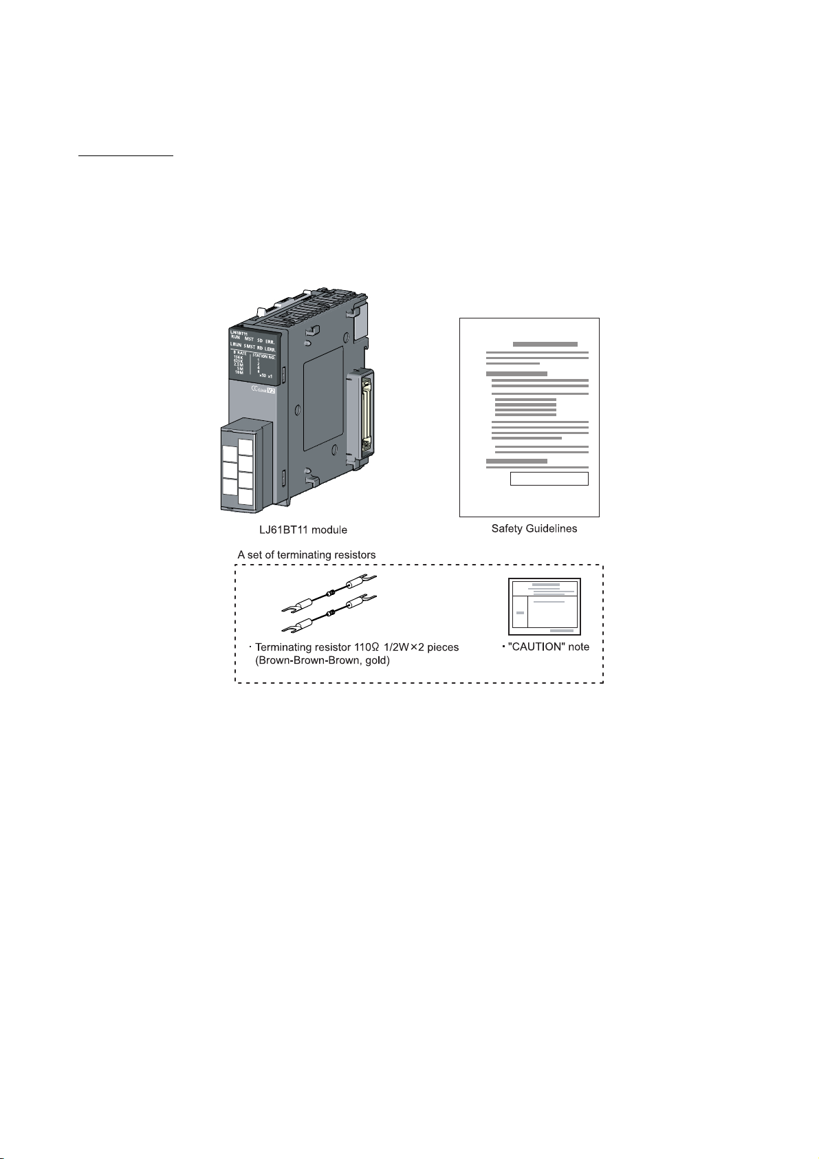
PACKING LIST
The LJ61BT11 package contains the following items. Before using the product, check if all of them are in the
package.
For the packaged items for L26CPU-BT, refer to MELSEC-L CPU Module User's Manual (Hardware Design,
Maintenance and Inspection).
A - 18 A - 18
Page 21
1 CC-Link SYSTEM
1 CC-Link SYSTEM
1.1 About CC-Link System
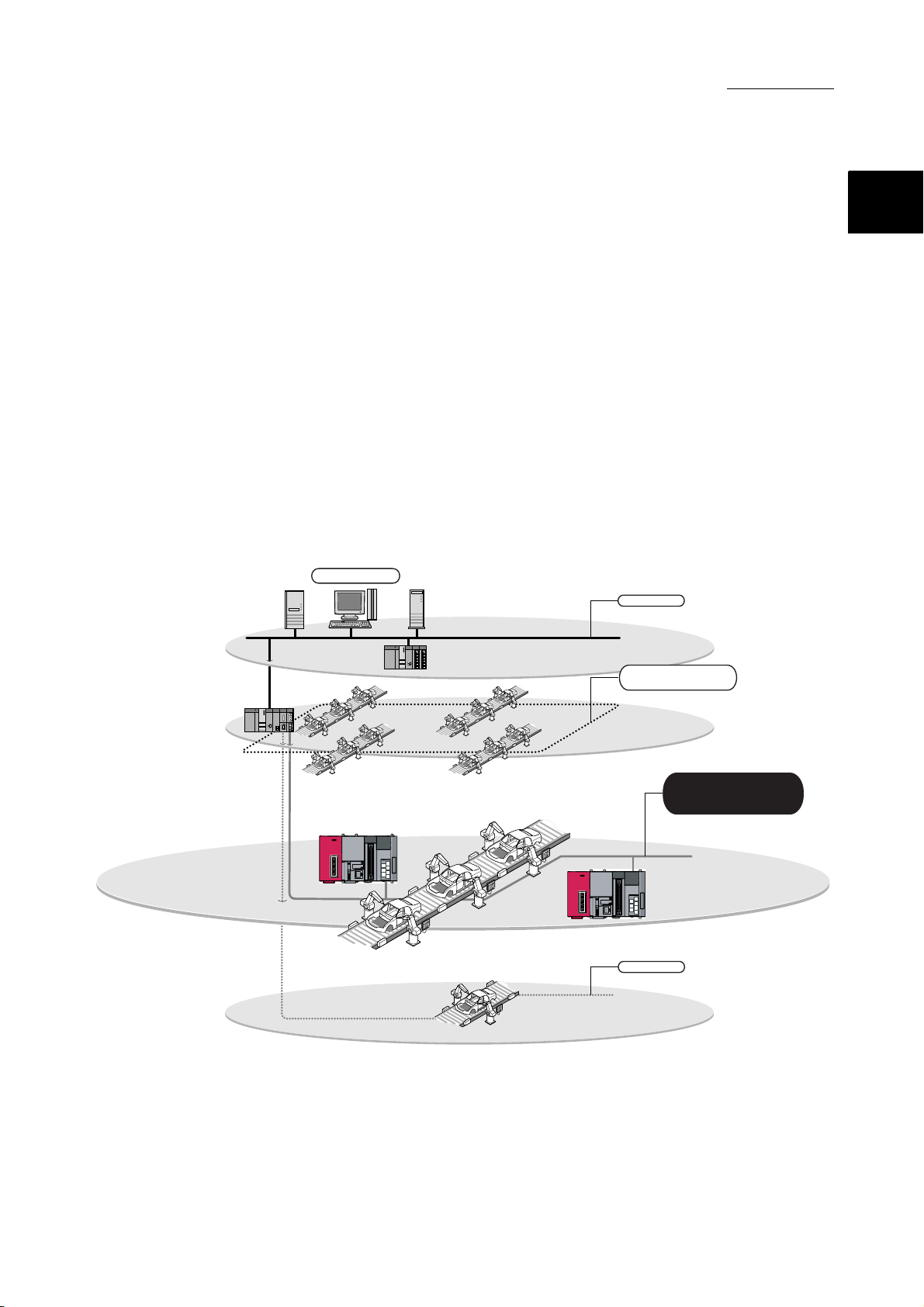
The CC-Link system is a system that connects distributed modules such as I/O modules,
intelligent function modules, and special function modules using dedicated cables so that
these modules can be controlled by a programmable controller CPU.
(1) By connecting each module separately to equipment such as a conveyor line or a
machine, the number of wires can be reduced in the entire system.
(2) Each module’s on/off information of input/output and numeric data can easily be
sent and received at high-speed.
(3) By connecting multiple programmable controller CPUs, a simple distributed
system can be configured.
(4) Since various devices from Mitsubishi's partner manufacturers can be connected,
the system can provide flexible solutions depending on the user’s requirements.
GX Works2
Ethernet
In factory (information control)
1
CC-Link IE
controller network
Between lines (production control)
CC-Link
In line (equipment control)
CC-Link/LT
In board and equipment
(device control and I/O control)
1 - 1 1 - 1
Page 22
1.2 Overview of Communication
1 CC-Link SYSTEM
1
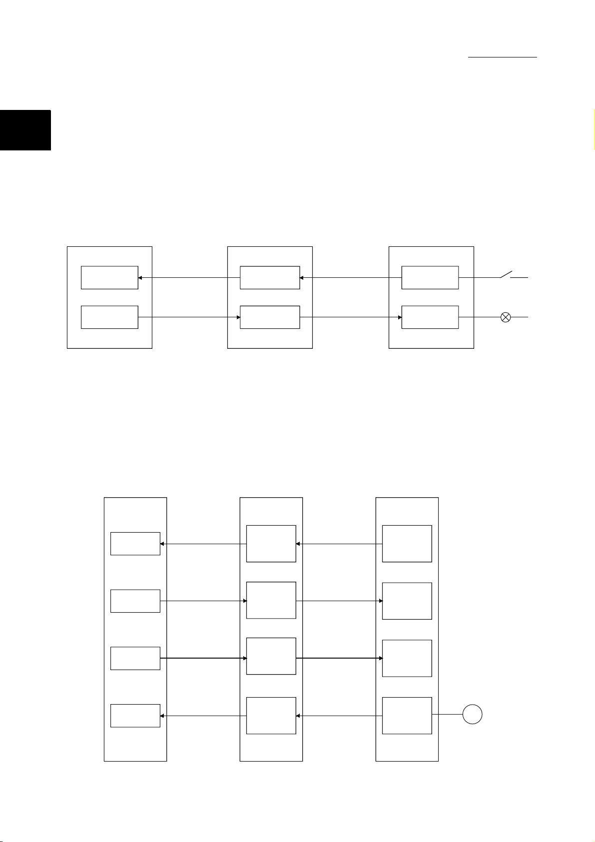
The overview of CC-Link communication is described below.
(1) Remote I/O station communication
The remote I/O station is a remote station that handles bit data only.
The ON/OFF information of a switch or indicator lamp is sent or received using
the remote input RX and remote output RY (refer to Section 8.1.1).
Programmable
controller CPU
Master station
Remote I/O station
X
Y
Automatic refresh
Automatic refresh
Remote input
RX
Remote output
RY
Link scan
Link scan
Input
Output
(2) Remote device station communication
Programmable
controller CPU
The remote device station is a remote station that handles bit and word data.
Signals for handshaking with the remote device station (initial request, error
occurred flag, etc.) are communicated using the remote input RX and remote
output RY. The setting data to the remote device station are communicated using
remote registers RWw and RWr (refer to Section 8.1.2).
Master station
Remote device station
X
Automatic refresh
Remote
input
(RX)
Link scan
Remote
input
(RX)
Y
Automatic refresh
W
Automatic refresh
W
Automatic refresh
Remote
output
(RY)
Remote
register
(RWw)
Remote
register
(RWr)
Link scan
Link scan
Link scan
Remote
output
(RY)
Remote
register
(RWw)
Remote
register
(RWr)
V
Voltmeter
1 - 2 1 - 2
Page 23
Programmable
controller CPU
1 CC-Link SYSTEM
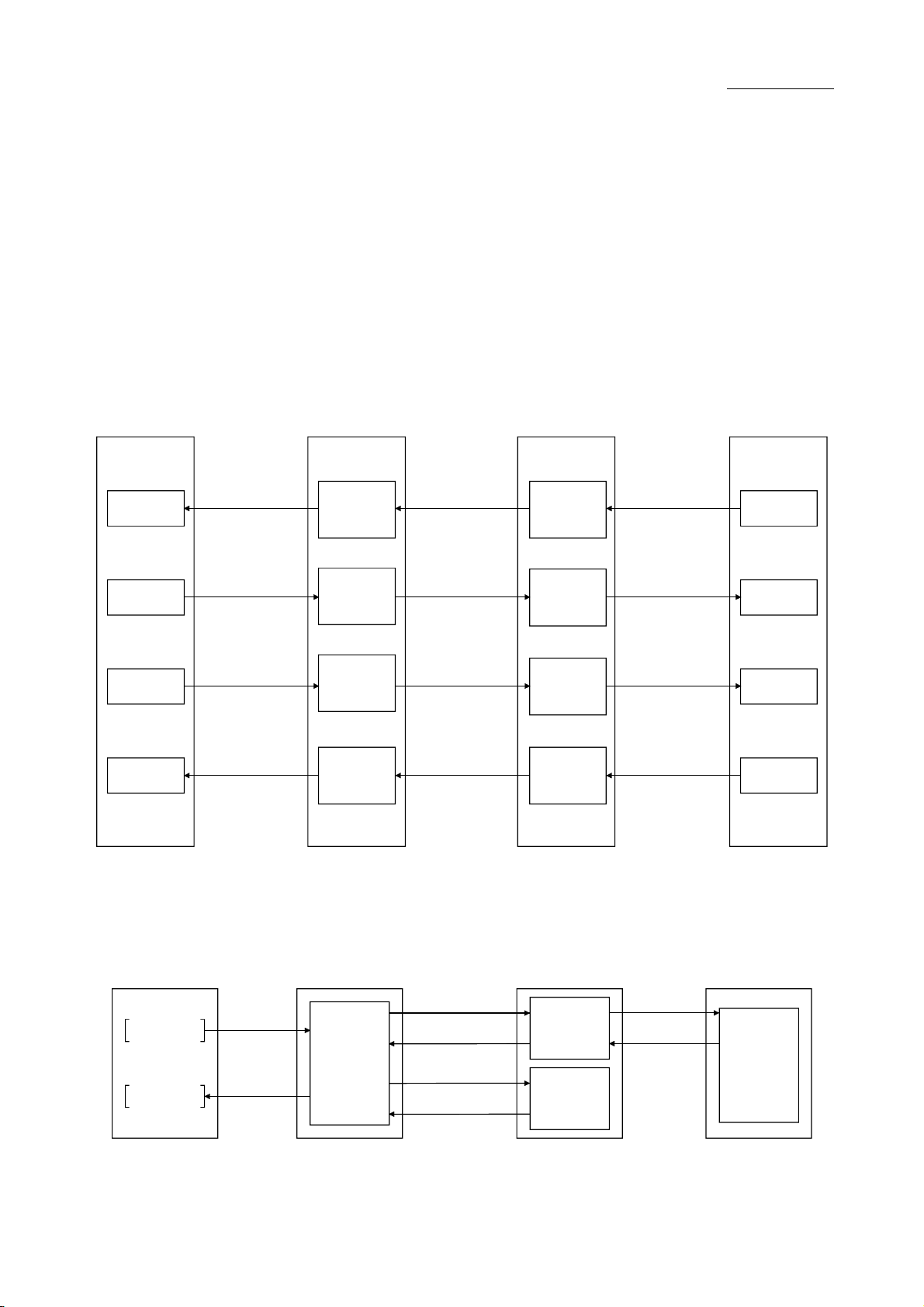
(3) Local station communication
The local station is a station having a programmable controller CPU and the
ability to communicate with the master and other local stations.
Communication between a master station and a local station uses two types of
transmission methods: cyclic transmission and transient transmission (refer to
Section 8.1.3).
(a) Cyclic transmission
Data communication between programmable controller CPUs can be
performed in N:N mode using bit data (remote input RX and remote output
RY) and word data (remote registers RWw and RWr).
Master station
Local station
Programmable
controller CPU
Programmable
controller CPU
X
Y
W
W
G(P).RIWT
G(P).RIRD
Automatic refresh
Automatic refresh
Automatic refresh
Automatic refresh
Remote
input
(RX)
Remote
output
(RY)
Remote
register
(RWw)
Remote
register
(RWr)
Link scan
Link scan
Link scan
Link scan
Remote
output
(RY)
Remote
input
(RX)
Remote
register
(RWr)
Remote
register
(RWw)
Automatic refresh
Automatic refresh
Automatic refresh
Automatic refresh
(b) Transient transmission
Read (G(P).RIRD) or write (G(P).RIWT) operation of the local station buffer
memory and CPU device can be performed at any timing.
Programmable
Master station
Transient
transmission
area
Transient transmission
Transient transmission
Transient transmission
Transient transmission
Local station
Transient
transmission
area
Buffer
memory
controller CPU
Y
X
W
W
W
1 - 3 1 - 3
Page 24
Programmable
controller CPU
1 CC-Link SYSTEM
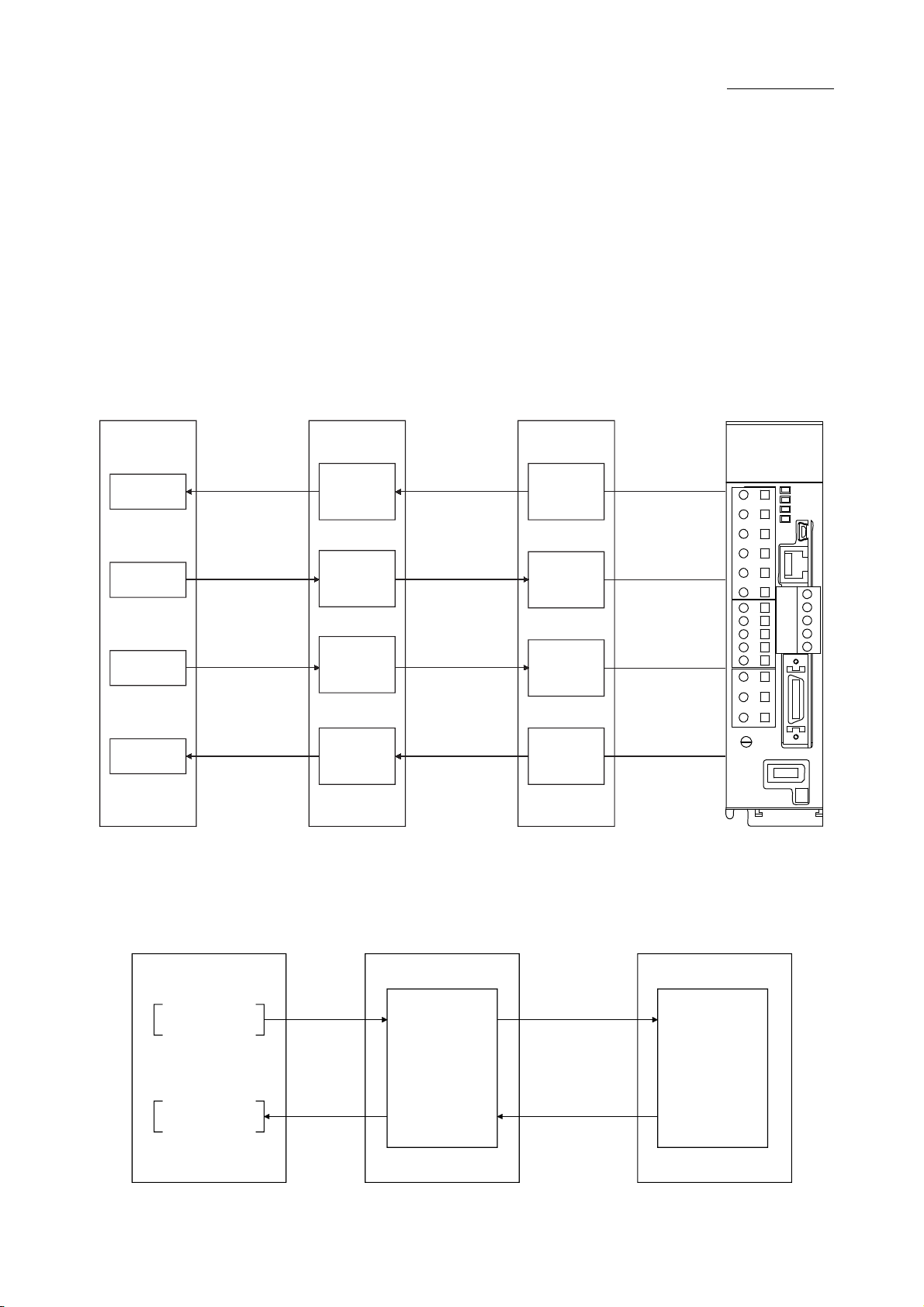
(4) Intelligent device station communication
The intelligent device station is a station that can handle bit and word data.
Communication between a master station and an intelligent device station uses
two types of transmission methods: cyclic transmission and transient
transmission (refer to Section 8.1.4).
(a) Cyclic transmission
Signals for handshaking with the intelligent device station (positioning start,
positioning complete, etc.) are communicated using the remote input RX and
remote output RY. Numeric data (positioning start number, present feed
value, etc.) is communicated using remote registers RWw and RWr.
Master station
Intelligent device station
Servo amplifier
X
Y
W
W
Automatic refresh
Automatic refresh
Automatic refresh
Automatic refresh
Remote
input
RX
Remote
output
RY
Remote
register
RWw
Remote
register
RWr
Link scan
Link scan
Link scan
Link scan
Remote
input
RX
Remote
output
RY
Remote
register
RWw
Remote
register
RWr
(b) Transient transmission
Reading (G(P).RIRD) or writing (G(P).RIWT) of buffer memory data in an
Programmable
controller CPU
intelligent device station is available at any timing.
Master station
Intelligent device station
G(P).RIWT
Transient
transmission
area
G(P).RIRD
Transient transmission
Buffer memory
Transient transmission
1 - 4 1 - 4
Page 25
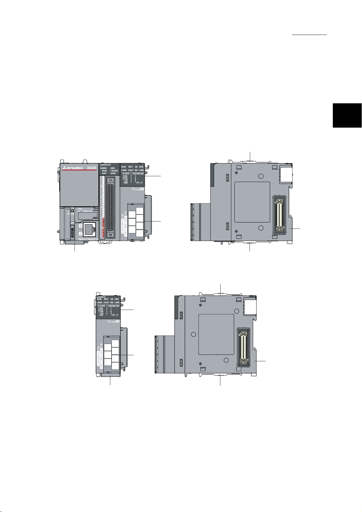
2 PART NAMES
2. PART NAMES
The following describes the parts names of the L series master/local modules.
(1) L26CPU-BT
For parts other than those for the built-in CC-Link functions, refer to the following
manual.
MELSEC-L CPU Module User's Manual (Hardware Design, Maintenance and
Inspection)
4)
1)
2)
2
5)
4)3)
(2) LJ61BT11
1)
2)
3) 4)
4)
5)
2 - 1 2 - 1
Page 26
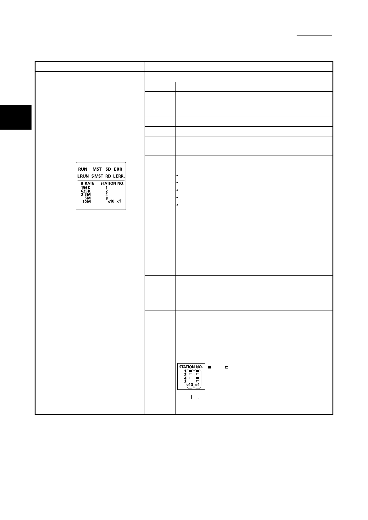
Number Name Description
2
1) LED indicators
The data link status can be checked with each ON/OFF status.
LED name Description
RUN
L RUN On: Data link is being executed
MST On: Operating as a master station. (in data link control)
S MST On: Operating as a standby master station. (in standby status)
SD On: Data being sent
RD On: Data being received
ERR.
L ERR.
B RATE
STATION
NO.
On : Operating normally
Off : Watchdog timer error
On: All stations have a communication error
This LED also turns on when the following errors occur.
There are more than one master station on the same line.
There is an error in the parameter settings.
The data link monitoring timer was activated.
The cable is disconnected.
The transmission path is affected by noise.
To check the source of the error, refer to Section 15.3.
Or, refer to Appendix 3.2 for details on SW0058 (detailed LED
display status).
Flashing: A communication error station identified, or remote
station No. duplicated.
On : Communication error (host)
Flashing: The terminating resistor is not attached. The module or
CC-Link Ver.1.10 compatible cable is affected by
noise.
On : Operating at the indicated transmission speed.
All off: Transmission speed auto following up
(When succeeded, the LED of the followed transmission
speed turns on.)
The module station number setting is indicated.
<Range>
Master station : 0 (All off)
Local station and standby master station : 1 to 64
(Example) When the station number 15 is indicated
: On : Off
2 PART NAMES
5
10
10 + 5 = 15
2 - 2 2 - 2
Page 27
Operating as a master station (data link control) Operating as a standby master station (standby)
Master station
MST
S MST
Station type and ON/OFF status of the "MST" and "S MST" LEDs
Operating status
Standby master
station
MST
S MST
Local station Master station
MST
S MST
MST
S MST
Standby master
station
S MST
MST
Number Name Description
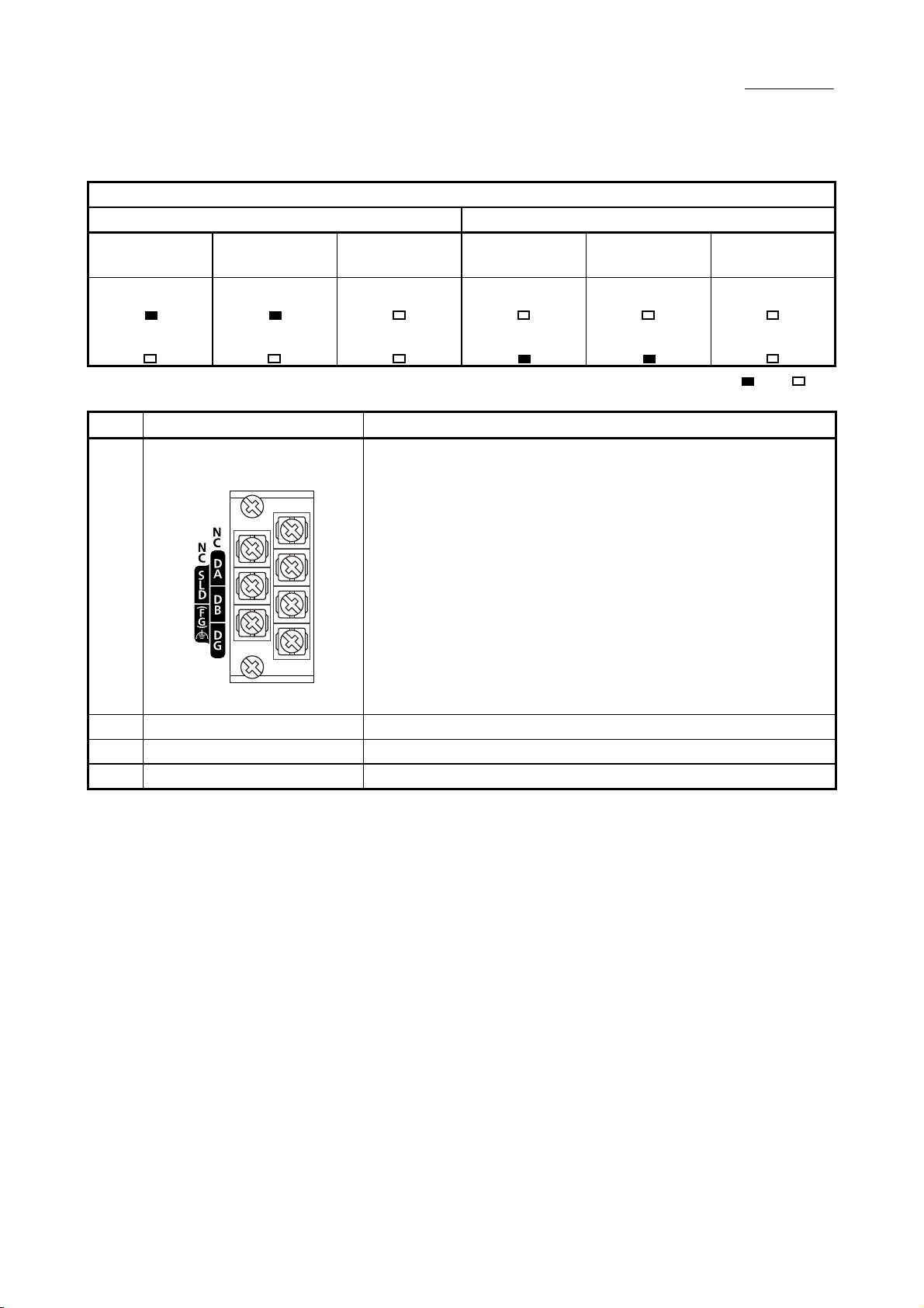
2) Terminal block
A CC-Link dedicated Ver.1.10 compatible cable is connected for data linking.
For the connection method, refer to Section 6.3.
Terminals SLD and FG are connected inside the module.
Since a 2-piece type terminal block is used, the module can be replaced
without disconnecting the signal lines to the terminal block.
(Shut off the external power supply for the system in all phases before
replacing the module.)
2 PART NAMES
Local station
MST
S MST
: On, : Off
3) Serial No. display part Displays the serial No. of the rating plate.
4) Module joint lever Fixes the connected modules.
5) DIN rail hook Used to install the module to the DIN rail.
2 - 3 2 - 3
Page 28
3 SPECIFICATIONS
3 SPECIFICATIONS
3.1 General Specifications
This chapter provides the specifications of the L series master/local modules.
For the general specifications of the L series master/local modules, refer to the
following manual.
"Safety Guidelines", the manual supplied with the CPU module or head module
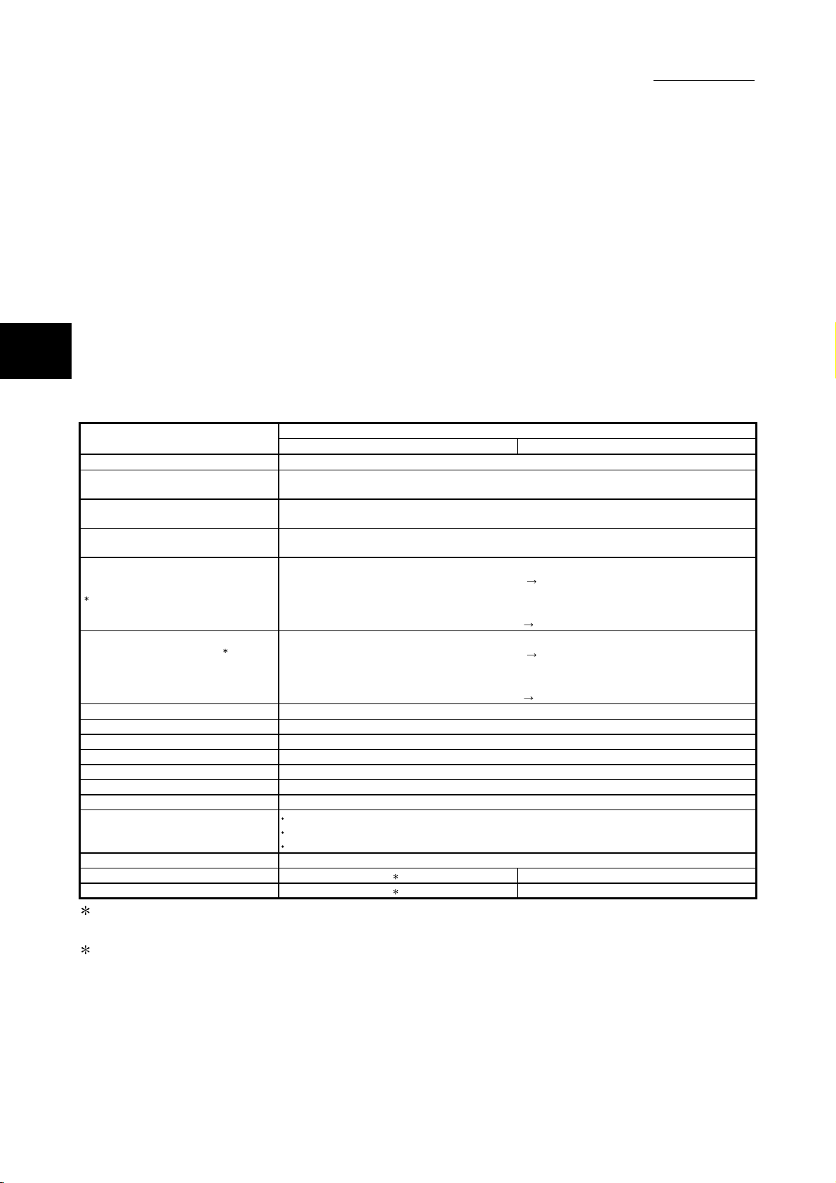
3.2 Performance Specifications
3
Transmission speed Can be selected from 156 kbps/ 625 kbps/ 2.5 Mbps/ 5 Mbps/ 10 Mbps
Maximum overall cable distance
(Maximum transmission distance)
Maximum number of connected stations
(master station)
Number of occupied stations
(local station)
Maximum number of link points per system
1
Number of link points per station 1
(remote station/local station/intelligent device
station/standby master station)
Communication method Broadcast polling method
Synchronous method Frame synchronization method
Encoding method NRZI method
Transmission path Bus (RS-485)
Transmission format Conforms to HDLC
Error control system CRC (X16 + X12 + X5 + 1)
Connection cable Ver.1.10 compatible CC-Link dedicated cable
RAS function
Number of occupied I/O points 32 points (I/O assignm ent: Intelligent 32 points)
5V DC internal current consumption 2 0.46A
Weight 2 0.15kg
Item
The following shows the performance specifications of the L series master/local
module.
Specification
Built-in CC-Link function LJ61BT11
Varies according to the transmission speed (Refer to Section 3.2.2)
64 (Refer to S ection 3.2.1)
1 to 4 stations
The number of stations can be switched by GX Works2 parameter setting.
Remote I/O (RX, RY) : 2048 points
Remote register (RWw) : 256 points (master station remote device station/local station/ intelligent
device station/standby master station)
Remote register (RWr) : 256 points (remote device station/local station/ intelligent device station/standby
Remote I/O (RX, RY) : 32 points (local station is 30 points)
Remote register (RWw) : 4 points (master station remote device station/local station/ intelligent
Remote register (RWr) : 4 points (remote device station/local station/ intelligent device station/standby
Automatic return function
Slave station cut-off function
Error detection by the link special relay/register
master station
device station/standby master station)
master station
master station)
master station)
1 Indicates the number of link points in remote net ver.1 mode. For the number of link points in remote net
Ver.2 mode and remote net additional mode, refer to Section 3.2 (1).
2 For the 5V DC internal current consumption and weight, refer to the following manual.
MELSEC-L CPU Module User's Manual (Hardware Design, Maintenance and Inspection)
3 - 1 3 - 1
Page 29
3 SPECIFICATIONS
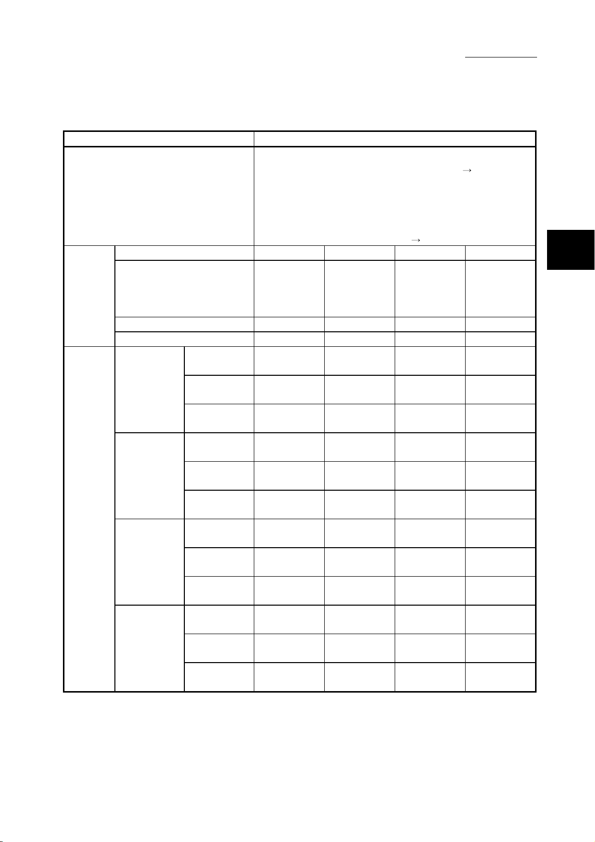
(1) Number of link points in remote net ver.2 mode or remote net
Item Specifications
Maximum No. of link points per system
Expanded cyclic setting Single Double Quadruple Octuple
No. of link
points per
station
Number
of link
points per
number of
occupied
stations
Remote I/O (RX/RY)
Remote register (RWw) 4 points 8 points 16 points 32 points
Remote register (RWr) 4 points 8 points 16 points 32 points
Occupies
1 station
Occupies
2 stations
Occupies
3 stations
Occupies
4 stations
additional mode
Remote I/O
(RX/RY)
Remote
register (RWw)
Remote
register (RWr)
Remote I/O
(RX/RY)
Remote
register (RWw)
Remote
register (RWr)
Remote I/O
(RX/RY)
Remote
register (RWw)
Remote
register (RWr)
Remote I/O
(RX/RY)
Remote
register (RWw)
Remote
register (RWr)
Remote I/O (RX/RY) : 8192 points
Remote register (RWw) : 2048 points (master station
station/local station/intelligent device
station/standby master station)
Remote register (RWr) : 2048 points (remote device station/local
station/intelligent device station/standby
master station
32 points
(30 points
for local
station)
32 points 32 points 64 points 128 points
4 points 8 points 16 points 32 points
4 points 8 points 16 points 32 points
64 points 96 points 192 points 384 points
8 points 16 points 32 points 64 points
8 points 16 points 32 points 64 points
96 points 160 points 320 points 640 points
12 points 24 points 48 points 96 points
12 points 24 points 48 points 96 points
128 points 224 points 448 points 896 points
16 points 32 points 64 points 128 points
16 points 32 points 64 points 128 points
32 points
(30 points
for local
station)
master station)
64 points
(62 points
for local
station)
remote device
128 points
(126 points
for local
station)
3
3 - 2 3 - 2
Page 30
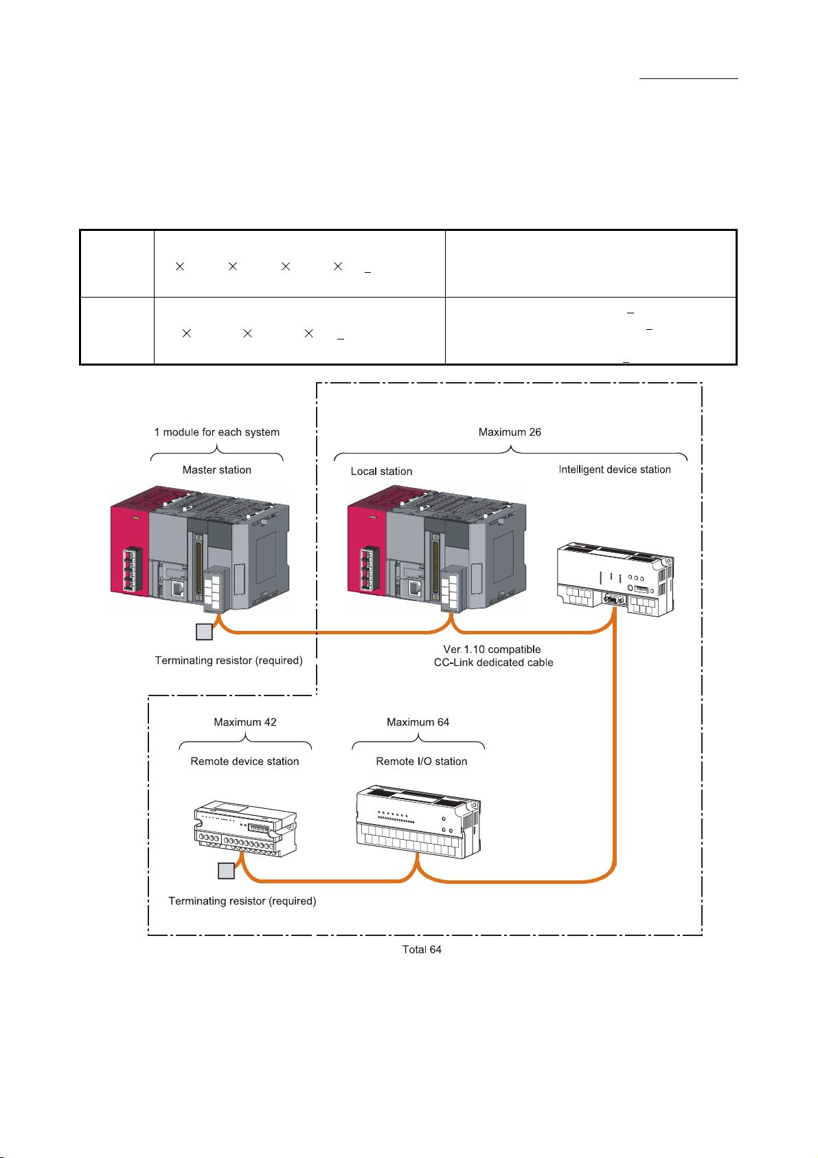
3.2.1 Maximum number of connected stations
(1) Remote net ver.1 mode
A total of 64 slave stations can be connected to a single master station.
Condition 1 {(1 a) + (2 b) + (3 c) + (4 d)} ≤ 64
Condition 2 {(16 A) + (54 B) + (88 C)} ≤ 2304
However, the following conditions must all be satisfied.
3 SPECIFICATIONS
a: Number of modules occupying 1 station
b: Number of modules occupying 2 stations
c: Number of modules occupying 3 stations
d: Number of modules occupying 4 stations
A: Number of remote I/O stations ≤
B: Number of remote device stations ≤
C: Number of local stations, standby master stations
and intelligent device stations ≤
64
42
26
3 - 3 3 - 3
Page 31

(2) Remote net ver.2 mode, remote net additional mode
A total of 64 slave stations can be connected to a single master station.
{(a + a2 + a4 + a8)
Condition 1
Condition 2
Condition 3
Condition 4 {(16 A) + (54 B) + (88 C) } ≤ 2304
+ (b + b2 + b4 + b8)
+ (c + c2 + c4 + c8) 3
+ (d + d2 + d4 + d8) 4} ≤ 64
32) + (a2 32) + (a4 64) + (a8 128)}
[{(a
+ {(b 64) + (b2 96) + (b4 192) + (b8 384)}
96) + (c2 160) + (c4 320) + (c8 640)}
+ {(c
+ {(d 128) + (d2 224) + (d4 448) + (d8 896)}] ≤ 8192
4) + (a2 8) + (a4 16) + (a8 32)}
[{(a
8) + (b2 16) + (b4 + 32) + (b8 64)}
+ {(b
+ {(c 12) + (c2 24) + (c4 48) + (c8 96)}
+ {(d 16) + (d2 32) + (d4 64) + (d8 128)}] ≤ 2048
However, the following conditions must all be satisfied.
2
3 SPECIFICATIONS
a: The total number of ver.1 compatible slave
stations that occupy 1 station, and ver.2
compatible slave stations that occupy 1 station
which are set to “Single”.
b: The total number of ver.1 compatible slave
stations that occupy 2 stations, and ver.2
compatible slave stations that occupy 2 stations
which are set to “Single”.
c: The total number of ver.1 compatible slave
stations that occupy 3 stations, and ver.2
compatible slave stations that occupy 3 stations
which are set to “Single”.
d: The total number of ver.1 compatible slave
stations that occupy 4 stations, and ver.2
compatible slave stations that occupy 4 stations
which are set to “Single”.
a2: The number of ver.2 compatible stations that
occupy 1 station which are set to “Double”.
b2: The number of ver.2 compatible stations that
occupy 2 stations which are set to “Double”.
c2: The number of ver.2 compatible stations that
occupy 3 stations which are set to “Double”.
d2: The number of ver.2 compatible stations that
occupy 4 stations which are set to “Double”.
a4: The number of ver.2 compatible stations that
occupy 1 station which are set to “Quadruple”.
b4: The number of ver.2 compatible stations that
occupy 2 stations which are set to “Quadruple”.
c4: The number of ver.2 compatible stations that
occupy 3 stations which are set to “Quadruple”.
d4: The number of ver.2 compatible stations that
occupy 4 stations which are set to “Quadruple”.
a8: The number of ver.2 compatible stations that
occupy 1 station which are set to “Octuple”.
b8: The number of ver.2 compatible stations that
occupy 2 stations which are set to “Octuple”.
c8: The number of ver.2 compatible stations that
occupy 3 stations which are set to “Octuple”.
d8: The number of ver.2 compatible stations that
occupy 4 stations which are set to “Octuple”.
A: Number of remote I/O stations ≤
B: Number of remote device stations ≤
C: Number of local stations, standby master
stations and intelligent device stations ≤
64
42
26
3 - 4 3 - 4
Page 32

3 SPECIFICATIONS
3 - 5 3 - 5
Page 33

3.2.2 Maximum overall cable distance
The relation of the transmission speed and maximum overcall cable distance when
configuring the entire system with products compatible with CC-Link Ver.1.10 or higher
and Ver.1.10 compatible CC-Link dedicated cables is shown below.
For the identification of the CC-Link Version, refer to the installation manual issued by
the CC-Link Partner Association.
3 SPECIFICATIONS
Version 1.10 compatible CC-Link dedicated cable (terminating resistor of 110Ω used)
Transmission speed Station-to-station cable length Maximum overall cable distance
156kbps 1200m
625kbps 900m
2.5Mbps 400m
5Mbps 160m
10Mbps
20cm or longer
100m
3 - 6 3 - 6
Page 34

3.2.3 Ver.1.10 compatible CC-Link dedicated cable
Use Ver.1.10 compatible CC-Link dedicated cables for the CC-Link system.
If a cable other than the Ver.1.10 compatible CC-Link dedicated cable is used, the
performance of the CC-Link system cannot be guaranteed.
For the specifications of the Ver.1.10 compatible CC-Link dedicated cables or any
other inquiries, visit the following website:
CC-Link Partner Association: http://www.cc-link.org/
REMARK
For details, refer to the CC-Link cable wiring manual issued by CC-Link Partner
Association.
3 SPECIFICATIONS
3 - 7 3 - 7
Page 35

3 SPECIFICATIONS
3.3 Function List
The following shows the function list of the L series master/local module.
Item Description Reference
Communication with remote I/O
stations
Communication with remote device
stations
Communication with local stations
Communication with intelligent
device stations
Item Description Reference
Slave station cut-off function
Automatic return function
Data link status setting when the
master station programmable
controller CPU has an error
Setting the status of input data from
a data link faulty station
Slave station refresh/compulsory
clear setting in case of
programmable controller CPU
STOP
Standby master function
Data link start by standby master
station
Block guarantee of cyclic data per
station
Guarantee of 32-bit data
3 - 8 3 - 8
(1) List of the "basic functions"
Performs on/off data communication with remote I/O stations. Section 8.1.1
Performs on/off data and numeric data communication with
remote device stations.
Performs on/off data and numeric data communication with local
stations.
Performs communication with intelligent device station, by cyclic
transmission, and transient transmissions.
(2) List of the "functions for improving system reliability"
Disconnects a slave station that cannot continue the data link
due to a reason such as power off, so that data link can continue
among normal slave stations only.
When a slave station, which has been disconnected from the
network due to a reason such as power off, returns to the normal
status, it automatically joins the data link.
Sets whether to stop or continue the data link when an error that
stops the operation occurs at the master station programmable
controller CPU in the system that has no standby master station.
When "Continue" is set, the diagnostics of the master station can
be performed from local stations.
Sets whether to clear or hold the input data (remote input RX)
from a station that detected a data link error due to a reason
such as power off.
Sets whether to refresh or forcibly clear output data (remote
output RY) to the slave stations when the programmable
controller CPU comes to STOP.
When "Clears Compulsorily" is set, the remote output RY turns
off when the operation stops due to STOP of programmable
controller CPU or due to an error occurrence.
Continues the data link by switching the control to the standby
master station when a problem occurs in the master station.
Starts data link when either of the master or standby master
station is turned on.
Guarantees the consistency of the cyclic data for each slave
station.
Guarantees the 32-bit data of the remote register (RWr/RWw)
between programmable controller CPU and the master/local
station.
Section 8.1.2
Section 8.1.3
Section 8.1.4
Section 8.2.1
Section 8.2.2
Section 8.2.3
Section 8.2.4
Section 8.2.5
Section 8.2.7
Section 8.2.8
Section 8.2.9
Section 8.2.10
Page 36

Item Description Reference
Remote device station initialization
procedure registration function
Event issuance for the interrupt
program
Automatic CC-Link startup
Reserved station function
Error invalid station setting function
Temporary error invalid station
setting function
Scan synchronous function
Data link stop/restart
Remote I/O station points setting
Master station duplication error
cancel function
Transmission speed auto following
setting
Status logging
(3) List of the "handy functions"
Programs for the initial setting become unnecessary, since the
initial settings in the remote device station are set at the network
parameter. The initial settings in the remote device station can
be configured easily.
Since the interrupt program of the programmable controller CPU
is executed according to the established event issuance
conditions, high speed data receive processing can be made
without being influenced by the sequence scan.
The CC-Link starts automatically, only by turning the power on,
and the operation at the system construction can be checked.
By setting slave stations that will be connected in the future as
reserved stations, they will not be treated as data link faulty
stations.
Prevents slave stations that may be powered off in the system
configuration from being treated as data link faulty stations by
setting the network parameters.
Changes slave stations without detecting errors during online
operation.
Also, prevents slave stations, which are turned off in the system
configuration, from being treated as data link faulty stations
temporarily.
Selects whether to synchronize or not the link scan with
sequence scan.
In the synchronous mode, the link scan is performed
synchronously with the sequence scan. Therefore, the output
data can be sent in high speed.
In the asynchronous mode, the link scan is performed not
synchronized to the sequence scan. Therefore, a high speed link
scan can be performed independent of the sequence scan.
Stops or restarts the data link that is being executed.
By stopping the data link, the program debug can be performed
efficiently, since data from other stations are not received, and
data are not sent from the host station.
Allows the I/O points of the remote I/O stations to be selected
from among 8 points, 16 points and 32 points, reducing the
number of reserved points.
The refresh device points of the programmable controller CPU
and the link refresh time can be saved.
Master station duplication errors can be canceled without turning
the power supply off to on, or without resetting the
programmable controller CPU.
When the host station is a local station or a standby master
station, an auto following occurs according to the transmission
speed of the master station, what eliminates setting errors of the
transmission speed.
Logs the data link status of all stations.
When multiple stations repeat normal/faulty, or when determined
stations and later repeat normal/faulty, this function enables
easy identification of the causes, such as contact failure of the
cable, or the noise occurrence location.
3 SPECIFICATIONS
Section 8.3.1
Section 8.3.2
Section 8.3.3
Section 8.3.4
Section 8.3.5
Section 8.3.6
Section 8.3.7
Section 8.3.8
Section 8.3.9
Section 8.3.10
Section 7.2 (2)
Section 15.4.3
3 - 9 3 - 9
Page 37

Item Description Reference
Transient transmission
(4) List of the "functions for transient transmission"
Specifies a target and communicates with it at any timing when
required.
3 SPECIFICATIONS
Section 9.1
3 - 10 3 - 10
Page 38

3.4 Mode Selection
CC-Link
Ver.1/
Ver.2
Ver.1
Ver.2
Mode
Remote I/O net
mode
Remote net ver.1
mode
Remote net
additional mode
Remote net ver.2
mode
3 SPECIFICATIONS
There are two different CC-Link versions: Ver.1 and Ver.2, and the L series
master/local modules are Ver.2-compatible modules.
The L series master/local modules have four types of modes for various systems.
(1) Overview of the modes
Connectable station
type
Remote I/O station
Remote I/O station
Remote device station
Intelligent device
station
Local station
Standby master station
Select this mode when the system consists of only
the master station and remote I/O stations.
Since the cyclic transmission speed is high, the
link scan time can be reduced.
Mode for complete compatibility with the
conventional module (Ver.1 compatible station).
Select this mode when the number of link points
need not to be increased.
Select this mode
when the number
of link points
need to be
increased.
Overview Reference
Section 3.4 (1) (a)
—
Select this mode when adding a
Ver.2 compatible slave station
to the existing Ver.1 system.
Select this mode when
configuring a new system.
Section 3.4.1 (2)
Section 3.4.1 (1)
(a) Link scan time according to the mode
Remote net ver.1 mode,
Number of stations Remote I/O net mode
8 0.61ms 1.2ms
16 0.94ms 1.6ms
32 1.61ms 2.3ms
64 2.94ms 3.8ms
Remote net additional mode,
Remote net ver.2 mode
(Transmission speed: 10Mbps)
[Setting method]
Set a mode for "Mode" in the Network Parameter setting of GX Works2.
(Refer to Section 7.2 to 7.5)
3 - 11 3 - 11
Page 39

3 SPECIFICATIONS
(2) Mode selection flowchart
The following flowchart explains the points of mode selection.
3 - 12 3 - 12
Page 40

3.4.1 Expanded cyclic setting
When increasing the number of link points, select the remote net ver.2 mode or the
remote net additional mode.
(1) Remote net ver.2 mode
This mode is designed to configure a new system.
The number of link points can be increased as indicated below.
Per station, RX/RY can be increased to up to 128 points and RWw/RWr to up to
32 points.
Per CC-Link network, RX/RY can be increased to up to 8192 points and
RWw/RWr to up to 2048 points.
Remote I/O station
(Station number 1:
Occupies 1 station)
Ver. 2
compatible
remote
output RY
Master station
Ver.2 mode
Station number 1
Station number 2
Station number 3
Station number 4
Station number 5
Station number 6
Output
Remote device station
Ver. 2 compatible
(Station number 2:
Occupies 1 station)
Remote output RY
Local station
Ver.2 mode
(Station number 3:
Occupies 4 stations)
Remote input RX
Station number 1
Station number 2
Station number 3
Station number 4
Station number 5
Station number 6
3 SPECIFICATIONS
Remote device station
Ver. 2 compatible
(Station number 7:
Occupies 1 station)
Station number 7
to
quadruple
Station number 7
to
double octuple
Remote output RY
POINT
(1) In the remote net ver.2 mode, the remote registers of the remote I/O station are
set to 0 points.
(2) When the ver.2 compatible slave station is added or deleted, the refresh devices
of the programmable controller CPU will vary by the number of points set to the
added or deleted slave station in the slave stations of the station numbers after
the added or deleted slave station. Confirm the varying number of points in
Section 3.2 (1).
3 - 13 3 - 13
Page 41

Ver. 1
compatible
remote
output RY
Master station
additional mode
Station number 1
Station number 2
Station number 3
3 SPECIFICATIONS
(2) Remote net additional mode
This mode is designed for use when slave stations including a ver.2 compatible
station is added to the existing ver.1 system.
The program of the existing system can be used as is.
Remote I/O station
(Station number 1:
Occupies 1 station)
Output
Remote device station
Ver. 1 compatible
(Station number 2:
Occupies 2 stations)
Remote output RY
Local station
additional mode
(Station number 4:
Occupies 4 stations)
Remote input RX
Station number 1
Station number 2
Station number 3
Remote device station
Ver. 2 compatible
(Station number 8:
Occupies 1 station)
Ver. 2
compatible
remote
output RY
to
Station number 4
Station number 5
Station number 6
Station number 7
Station number 8
to
to
Station number 4
Station number 5
Station number 6
Station number 7
POINT
Station number 8
to
double octuple
Remote output RY
(1) Set the station numbers of the slave stations to be added after the last station
number used in the existing system.
In the above example, the slave stations are added to and after station No. 4
since the existing system uses up to station No. 3.
(2) When the ver.2 compatible slave station is added or deleted, the refresh devices
of the programmable controller CPU will vary by the number of points set to the
added or deleted slave station in the slave stations of the station numbers after
the added or deleted slave station. Confirm the varying number of points in
Section 3.2 (1).
(3) In the remote net additional mode, the ver.2 compatible slave station must be
placed in the latter half as described in (1).
When there is a possibility that ver.1 compatible slave stations will be added in
the future in the remote net additional mode, set multiple reserved stations after
the ver.1 compatible slave station to ensure ease of expanding the system.
(4) For the system that includes a standby master station, it is recommended to
change for the remote net ver.2 mode.
When the remote net additional mode is used, the program for the standby
master station must be corrected.
3 - 14 3 - 14
Page 42

3 SPECIFICATIONS
(3) Mode combination
(a) Whether system can be configured or not
The following table indicates whether cyclic transmission can be made or not
in each station.
Slave station
Master station
L series
master/local
module
Addition
al mode
Ver.2
mode
Ver.1
mode
Ver.2
mode
: Cyclic transmission enabled, : Cyclic transmission enabled on condition, : Cyclic transmission disabled
L series master/local module,
QJ61BT11N,
Q81BD-J61BT11,
Q80BD-J61BT11N
Local station Standby master station
2
Additional
mode
Ver.1
Ver.2
mode
1
1
Additional
mode
mode
Ver.1
mode
A1SJ61BT11
A1SJ61QBT11
Local
station
Ver.1
mode
1
1
3
3
Intelligent device station
Standby
master
station
Ver.1
mode
Ver.2
compatible
Ver.1
compatible
Remote station4
Remote device station
Ver.2
compatible
compatible
1 The local station can communicate with the master station when the local station
mode is the remote net ver.1 mode. However, Ver.2 compatible stations are
recognized as faulty so that data of these stations cannot be confirmed.
Master station
Ver. 2 mode
Ver. 2 compatible
remote output RY
Station number 1
Station number 2
Station number 3
Station number 4
Local station
Ver. 2 mode
(Station number 1:
Occupies 1 station)
Ver. 2 compatible
remote input RX
Station number 1
Station number 2
Station number 3
Station number 4
Local station
Ver. 1 mode
(Station number 2:
Occupies 1 station)
Remote input RX
Station number 1
Station number 2
Station number 3
Station number 4
Remote device station
Ver. 2 compatible
(Station number 3:
Occupies 1 station)
All 0s
Remote output RY
Remote device station
Ver.1
Ver. 1 compatible
(Station number 4:
Occupies 1 station)
Remote output RY
Remote I/O
station
Ver.1
compatible
to
to
double
quadruple
3 - 15 3 - 15
Page 43

3 SPECIFICATIONS
2 A link is performed as shown in the following areas.
Ver. 1
compatible
remote
output RY
Ver. 2
compatible
remote
output RY
Master station
additional mode
Station number 1
to
Station number 2
Station number 3
Station number 4
Station number 5
Station number 6
Local station
Ver. 1 mode
(Station number 1:
Occupies 1 station)
Station number 1
Station number 2
Station number 3
Station number 4
Station number 5
Station number 6
Station number 7
to
Local station
Ver. 2 mode
(Station number 2:
Occupies 1 station)
Station number 1
Station number 2
Station number 3
Station number 4
Station number 5
Station number 6
Local station
additional mode
(Station number 3:
Occupies 4 stations)
Remote input RX
Station number 1
to
Station number 2
Station number 3
Station number 4
Station number 5
Station number 6
Standby master station
additional mode
(Station number 7:
Occupies 1 station)
Station number 1
to
Station number 2
Station number 3
Station number 4
Station number 5
Station number 6
Station number 7
to
Station number 7
to
double
Station number 7
to
double
Station number 7
to
octuple
3 The remote net ver.2 mode and remote net additional mode cannot be used with
the QJ61BT11.
4 Data link is not available when the version set in the station type of the master
station information is different from that of the remote station.
For example, when the station type of the master station information is set as
"Ver.1 remote device station" although the actual remote device station is set to
"Ver.2 remote device station", data link cannot be performed with the "ERR." LED
on the master station flashing and the "L RUN" LED on the remote device station
turned OFF.
3 - 16 3 - 16
Page 44

Send station
Master
station
L series
master/local
module,
QJ61BT11N
Local
station
Intelligent device station
Remote device station
Remote I/O station
3 SPECIFICATIONS
(b) Whether send/receive is enabled or not
The following table indicates whether send/receive of cyclic data is enabled
or not.
Receive station
mode
mode
Ver.1
mode
mode
mode
Ver.1
mode
Ver.2 compatible area — — — — — — Ver.2
Ver.1 compatible area — — — — — —
Ver.2 compatible area — — — — — — Additional
Ver.1 compatible area — — — — — —
Ver.2 compatible area — — — — — —
Ver.1 compatible area — — — — — —
Ver.2 compatible area — — Ver.2
Ver.1 compatible area — — — — — —
Ver.2 compatible area — — — — Additional
Ver.1 compatible area — — — — — —
Ver.2 compatible area — — — — — —
Ver.1 compatible area
Ver.2 compatible — —
Ver.1 compatible — —
Ver.2 compatible — —
Ver.1 compatible — —
Ver.1 compatible — —
Ver.2 mode Additional mode Ver1 mode
Ver.2
compatible
area
compatible
— —
L series master/local module,
Ver.1
area
Ver.2
compatible
area
QJ61BT11N
Master station
Ver.1
compatible
compatible
area
Ver.2
area
Ver.1
compatible
area
3 - 17 3 - 17
Page 45

3 SPECIFICATIONS
L series master/local module,
QJ61BT11N
Local station
Ver.2 mode Additional mode Ver1 mode
Ver.2
compatible
area
— — — —
— — — — — — — — — — —
— — —
— —
— — — — — — — — — — —
— — — — — —
— — — — — — — —
— — — — — — — — — — —
— — — — — — —
— — — — — — — — — — —
— — — — — — — — — — —
— — — — — — —
— — — — — — —
— — — — — — —
— — — — — — —
— — — — — — —
— — — — — — —
Ver.1
compatible
area
Ver.2
compatible
area
Ver.1
compatible
area
Ver.2
compatible
area
Ver.1
compatible
area
Intelligent device
station
Ver.2
compatible
Ver.1
compatible
Remote device station
Ver.2
compatible
Ver.1
compatible
Remote
I/O station
Ver.1
compatible
: Cyclic transmission enabled, : Cyclic transmission disabled, —: Prohibited
3 - 18 3 - 18
Page 46

3.5 I/O Signal List
The following describes the I/O signal list of the L series master/local module. The "n"
in the table indicates the master/local module's first I/O number of the L series, which is
determined by both the installation position and the module installed before the L
series master/local module.
<Example> When the master/local module's first I/O number of the L series is X/Y30
Xn0 to X (n + 1) F
Programmable controller CPU
Input number Signal name
Xn0 Module error
Xn1 Host data link status
Xn2 Use prohibited — — Yn2
Xn3 Other station data link status
Xn4 Yn4
Xn5 Yn5
Xn6 Yn6
Xn7 Yn7
Xn8 Yn8
Xn9 Yn9
XnA YnA
XnB YnB
XnC YnC
XnD YnD
XnE
XnF Module ready
X (n+1) 0 Y (n+1) 0
X (n+1) 1 Y (n+1) 1
X (n+1) 2 Y (n+1) 2
X (n+1) 3 Y (n+1) 3
X (n+1) 4 Y (n+1) 4
X (n+1) 5 Y (n+1) 5
X (n+1) 6 Y (n+1) 6
X (n+1) 7 Y (n+1) 7
X (n+1) 8 Y (n+1) 8
X (n+1) 9 Y (n+1) 9
X (n+1) A Y (n+1) A
X (n+1) B Y (n+1) B
X (n+1) C Y (n+1) C
X (n+1) D Y (n+1) D
X (n+1) E Y (n+1) E
X (n+1) F
Signal direction:
L series master/local module
Use prohibited — —
Use prohibited — —
Yn0 to Y (n + 1) F
Availability Availability
Master station Local station
POINT
The use-prohibited output signals shown in the I/O signal list are used by the
system and cannot be used by the user.
In the event these signals are used (turned on/off) by the user, normal operations
cannot be guaranteed.
X30 to X4F
Y30 to Y4F
Programmable controller CPU L series master/local module
Output number Signal name
Yn0
Yn1
Yn3
YnE
YnF
Y (n+1) F
3 SPECIFICATIONS
Signal direction:
Master station Local station
Use prohibited — —
3 - 19 3 - 19
Page 47

3.6 Buffer Memory List
The buffer memory is used for data exchange between the L series master/local
module and a programmable controller CPU.
Data can be read or written by parameter settings in GX Works2 or with dedicated
instructions.
The contents of the buffer memory return to the default when the power is turned OFF
or the programmable controller CPU is reset.
Address Availability
Hexadecimal Decimal
0H
to
DF
E0H
to
15F
160H
to
1DF
1E0H
to
2DF
H
H
H
H
0
to
223
224
to
351
352
to
479
480
to
735
2 Used when the remote net ver.1 mode or the remote net additional mode is selected.
The following shows the buffer memory list.
Item Description
Parameter information
area
Remote input (RX)
Remote output (RY)
Remote register
(RWw)
Master station:
For sending
Local station:
For sending/receiving
2
Stores the parameter settings. Read only
For the master station: Stores the input status
2
For the local station : Stores the input status
For the master station: Stores the output status to
For the local station : Stores the output status to
2
For the master station: Stores the send data to
For the local station : Stores the send data to the
from the slave stations.
from the master station.
the slave stations.
the master station.
Also, stores the receive
data from the remote/other
local/intelligent
device/standby master
stations.
the remote device/all local
/intelligent device/standby
master stations.
master/other
local/intelligent
device/standby master
stations.
Also, stores the receive
data from the remote
device/other
local/intelligent
device/standby master
stations.
Read/write
possibility
Read only
Write only
Read/write
enabled
Write only
Read/write
enabled
: Available, — : Not available
3 SPECIFICATIONS
Local
station
—
—
—
—
Reference
Appendix
Appendix
Appendix
Master
station
—
—
—
(To the next page)
2 (1)
2 (2)
2 (3)
3 - 20 3 - 20
Page 48

Address Availability
Hexadecimal Decimal
2E0H
to
3DF
3E0H
to
5DF
5E0H
to
5FF
600H
to
7FF
800H
to
9FF
A00H
to
FFF
H
H
H
H
H
H
736
to
991
992
to
1503
1504
to
1535
1536
to
2047
2048
to
2559
2560
to
4095
Remote register
(RWr)
Master station:
For receiving
Local station:
For receiving
Slave station offset,
size information
Link special relay (SB) Stores the data link status.
Link special register
(SW)
Use prohibited
Random access buffer
Item Description
For the master station: Stores the receive data
2
from the remote
device/local/intelligent
device/standby master
stations.
For the local station : Stores the receive data
from the master station.
Stores the offset and size of RX/RY/RWw/RWr
per slave station.
Stores the data link status.
1
— — — — —
The specified data is stored and used by
transient transmission.
Read/write
possibility
Read only
Read only
Read/write
enabled
(write may
be disabled
depending
on the
device)
Read/write
enabled
Stores the send and receive data and control
1000H
to
1FFF
4096
to
Communication buffers
8191
H
data when performing transient transmission
(communication using this buffer) with the local
station, standby master station, and intelligent
Read/write
enabled
device station.
2000H
to
2FFF
3000H
to
3FFF
8192
12287
H
Automatic update
to
buffer
12288
Use prohibited
to
16383
H
Stores the automatically updated data when
performing transient transmission with the
AJ65BT-R2N (communication using the
automatic update buffer).
1
— — — — —
Read/write
enabled
: Available, — : Not available
1 Do not write any data to the use-prohibited area. Doing so may cause an error.
2 Used when the remote net ver.1 mode or remote net additional mode is selected.
3 SPECIFICATIONS
Local
station
—
Reference
Appendix
Appendix
Master
station
—
Appendix
Appendix
—
Appendix
Appendix
Appendix
(To the next page)
2 (3)
2 (4)
2 (5)
2 (6)
2 (7)
2 (8)
2 (9)
3 - 21 3 - 21
Page 49

Address Availability
Hexadecimal Decimal
4000H
to
41FF
16384
to
16895
H
Ver.2 compatible
remote input (RX)
Item Description
For the master station: Stores the input status
3
For the local station : Stores the input status
from the slave stations.
from the master station.
For the master station: Stores the output status to
the slave stations.
For the local station : Stores the output status to
4200H
to
43FF
16896
17407
H
Ver.2 compatible
to
remote output (RY)
3
the master station.
Also, stores the receive
data from the remote/other
local/intelligent
device/standby master
stations.
For the master station: Stores the send data to
the remote device/all local
/intelligent device/standby
master stations.
4400H
to
4BFF
Ver.2 compatible
remote register
to
(RWw)
Master station:
For sending
17408
19455
H
3
Local station:
For sending/receiving
For the local station : Stores the send data to the
master/other
local/intelligent
device/standby master
stations.
Also, stores the receive
data from the remote
device/other
local/intelligent
device/standby master
stations.
For the master station: Stores the receive data
4C00H
to
53FF
Ver.2 compatible
remote register
3
to
(RWr)
Master station:
For receiving
19456
21503
H
Local station:
For the local station : Stores the receive data
For receiving
from the remote
device/local/intelligent
device/standby master
stations.
from the master station.
Read/write
possibility
Read only
Write only
Read/write
enabled
Write only
Read/write
enabled
Read only
3 SPECIFICATIONS
Master
Local
station
station
—
—
—
—
—
—
—
—
Reference
Appendix
2 (10)
Appendix
2 (11)
5400H
to
7FFF
21504
Use prohibited
to
32767
H
1
— — — — —
: Available, — : Not available
1 Do not write any data to the use-prohibited area. Doing so may cause an error.
3 Used when the remote net ver.2 mode or remote net additional mode is selected.
3 - 22 3 - 22
Page 50

4 PROCEDURE BEFORE OPERATION
4 PROCEDURE BEFORE OPERATION
4
This chapter explains the procedure before operation.
The following describes the procedure before operation.
4 - 1 4 - 1
Page 51

4 PROCEDURE BEFORE OPERATION
4
4 - 2 4 - 2
Page 52

5 SYSTEM CONFIGURATION
5 SYSTEM CONFIGURATION
This chapter explains the system configuration of the L series master/local module and
the number of connectable modules.
5.1 System Configuration
5.1.1 System configuration of the L series master/local modules
(1) When using the built-in CC-Link function
Power supply module L26CPU-BT END cover
5
(2) When using the LJ61BT11
(a) Connecting to the CPU module
Power supply module L02CPU LJ61BT11 END cover
(b) Connecting to the head module
5 - 1 5 - 1
Page 53

5 SYSTEM CONFIGURATION
5.1.2 System configuration on CC-Link
The following shows a system configuration.
5
5 - 2 5 - 2
Page 54

5.2 Applicable System
Applicable programmable controller CPUs and precautions on the system
configuration are described below.
5.2.1 Applicable modules and number of connectable modules
(1) Modules applicable to the LJ61BT11, and number of connectable
modules
Refer to the following manual.
MELSEC-L CPU Module User's Manual (Hardware Design, Maintenance and
Inspection)
MELSEC-L CC-Link IE Field Network Head Module User's Manual
(2) Compatible software package
Refer to the following manual.
MELSEC-L CPU Module User's Manual (Hardware Design, Maintenance and
Inspection)
MELSEC-L CC-Link IE Field Network Head Module User's Manual
(3) Usable slave stations
Both of ver.1 and ver.2 compatible slave stations can be used.
5.2.2 Restrictions on use with the head module
5 SYSTEM CONFIGURATION
The following shows the restrictions when using the LJ61BT11 connected to the head
module.
(1) "Interrupt Setting" in Network Parameter is not available.
(2) The automatic CC-Link startup function cannot be used.
(3) Dedicated instructions cannot be used.
In addition, the following slave stations cannot be connected when parameters
are set with dedicated instructions.
AJ65BT-R2N
AJ65BT-D75P2-S3
5 - 3 5 - 3
Page 55

5.2.3 Precautions on the system configuration
The system should be designed with the following considerations to prevent mis-input
from the remote I/O modules:
(1) When powering on or off
Start the data link after turning on the power to remote I/O modules. Turn off the
power to remote I/O modules after stopping the data link.
5 SYSTEM CONFIGURATION
Data link start Data link stop
Master module
(data link status)
Remote I/O module
(power status)
During operation
During stop
ON
OFF
(2) During momentary power failure of remote I/O modules
When a momentary power failure occurs in the power (24 V DC) supplied to
remote I/O modules, mis-input may occur.
(a) Cause for mis-input due to a momentary power failure
The remote I/O module hardware uses the power by internally converting
the module power (24 V DC) to 5 V DC.
When a momentary power failure occurs in a remote I/O module, the
following condition occurs:
(Time for the 5 V DC power in the remote I/O module to turn off) >
(Response time for input module on
off)
Therefore, mis-input occurs when a refresh is performed within the time
indicated by 1) in the figure below.
1)
Remote I/O module
(module power supply and input
external supply power)
Remote I/O module (internal 5 V DC)
Input (Xn)
When the input external power supply turns OFF, the
input (Xn) turns OFF after the response time for the
input module to change from ON to OFF.
5 - 4 5 - 4
Page 56

(b) Countermeasure for mis-input
To the power supply module, the stabilized power supply and the external
supply power of AC input, connect power cables from the same power
For DC input
source.
5 SYSTEM CONFIGURATION
For AC input
REMARK
When supplying power from a single power source to multiple remote I/O modules,
select the proper type of cable and perform the wiring, taking into account a voltage
drop.
Connections can be established if the receiving port voltage at the remote I/O
module is within the specified range of the remote I/O module to be used.
5 - 5 5 - 5
Page 57

5 SYSTEM CONFIGURATION
(3) Access to station No.64
(a) To a local station of No. 64, other station access from GX Works2 or GOT
is not allowed. If the station No. is changed to any of 0 to 63, other station
access is executable.
(b) From the CC-Link board, other station access is not allowed to access a
local station or intelligent device station whose station No. is 64. If the
station No. is changed to any of 0 to 63, other station access is executable.
(4) Precautions on the retry count setting for use of dedicated
instructions
Note that some dedicated instructions are not applicable to the retry count
setting. For details, refer to Section 9.1.1 (3).
For the retry count setting for use of dedicated instructions, there are no
restrictions on CPU module models.
5 - 6 5 - 6
Page 58

6 INSTALLATION AND CONNECTION
6 INSTALLATION AND CONNECTION
This chapter describes the installation and connection of the L series master/local
modules.
6.1 Module Installation Environment and Position
Refer to the following manual.
MELSEC-L CPU Module User's Manual (Hardware Design, Maintenance and
Inspection)
MELSEC-L CC-Link IE Field Network Head Module User's Manual
6.1.1 Handling precautions
(1) Before installing or removing the module, shut off the external power supply
for the system in all phases.
Failure to do so may result in electric shock or cause the module to fail or
malfunction.
(2) Use the programmable controller in an environment that meets the general
specifications shown in "Safety Guidelines", the manual supplied with the
CPU module or head module.
Failure to do so may result in electric shock, fire, malfunction, and damage
to or deterioration of the product.
(3) Do not drop the module case and terminal block and do not apply a strong
impact since they are made of resin.
(4) Do not remove the printed-circuit board of each module from its case. This
may cause a failure in the module.
(5) To interconnect modules, engage the respective connectors and securely
lock the module joint levers.
Incorrect interconnection may cause malfunction, failure, or drop of the
module.
(6) Do not directly touch any conductive parts and electronic components of the
module.
Doing so may cause malfunction or failure of the module.
(7) Prevent foreign matter such as dust or wire chips from entering the module.
Such foreign matter can cause a fire, failure, or malfunction.
(8) A protective film is attached to prevent foreign matter, such as wire chips,
from entering the module during wiring. Do not remove this film until the
wiring is complete. Remove it for heat dissipation before system operation.
6
6 - 1 6 - 1
Page 59

6 INSTALLATION AND CONNECTION
(9) Solderless terminals with insulation sleeve cannot be used for the terminal
block. It is recommended to cover the connection part of the solderless
Terminal block screw (M3 screw) 0.42 to 0.58 N · m
Terminal block mounting screw (M3.5 screw) 0.66 to 0.89 N · m
(1) Be sure to power off the station before installing or removing the terminal block.
(2) Always power off the system in advance when installing or removing a
terminal with a marking tube or an insulation tube.
(10) Before handling the module, touch a conducting object such as a grounded
metal to discharge the static electricity from the human body.
Failure to do so may cause the module to fail or malfunction.
(11) Tighten the terminal screws within the following torque range.
Screw Tightening torque range
POINT
If the terminal block is installed or removed without powering off the station,
correct data transmission cannot be guaranteed.
terminating resistor to change the system. If the terminating resistor is installed
or removed while the system is energized, normal data transmission will not be
guaranteed.
6
6 - 2 6 - 2
Page 60

6.2 Hardware Test
6 INSTALLATION AND CONNECTION
The hardware test checks whether or not each module works properly by itself. Always
perform this hardware test before configuring the system.
POINT
Be sure to execute the hardware test in the following status.
(1) Perform this hardware test by itself and without connecting any CC-Link
Ver.1.10 compatible cable. If the hardware test is performed with the cable
connected, it may result in an abnormal termination.
(2) Execute the hardware test in the condition where no CPU error has occurred. If
the hardware test is performed with a CPU error occurred, the test may not be
completed.
Execute the hardware test using the following procedure.
6 - 3 6 - 3
Page 61

6 INSTALLATION AND CONNECTION
6 - 4 6 - 4
Page 62
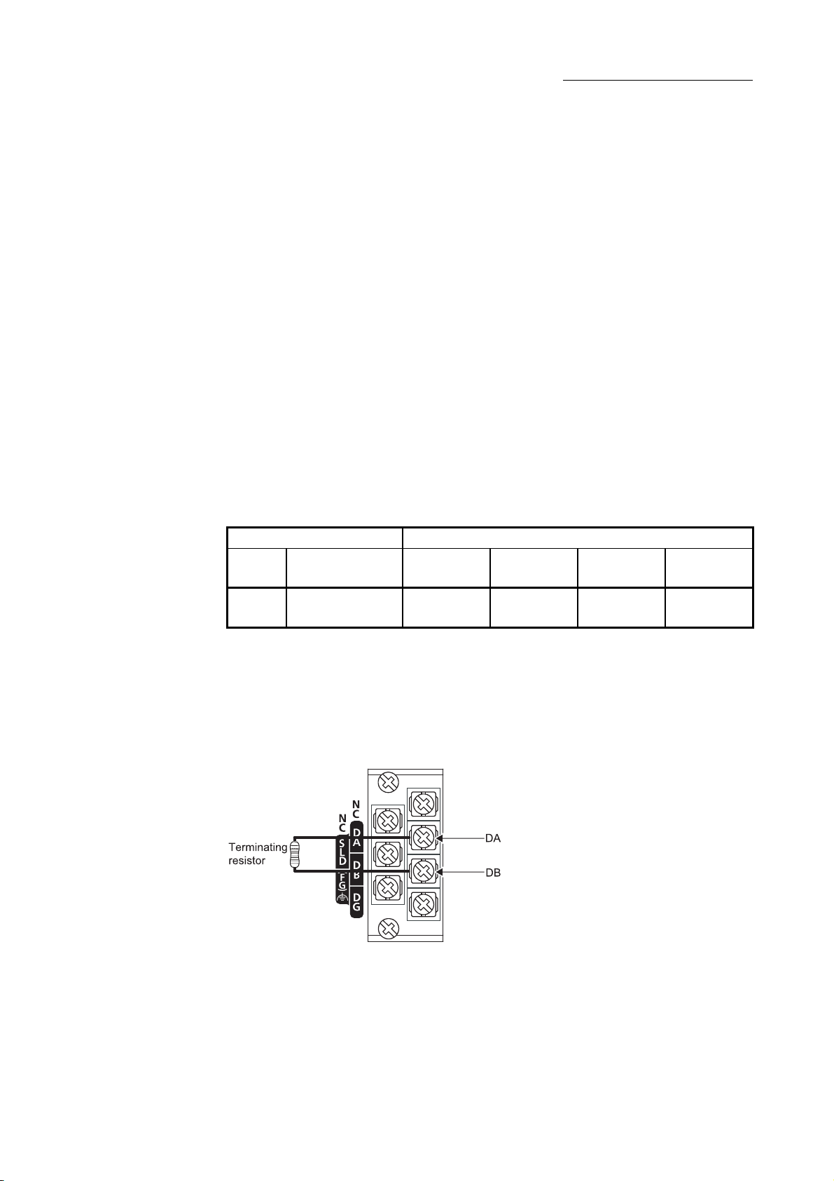
6 INSTALLATION AND CONNECTION
6.3 Connecting Modules with Ver.1.10 Compatible CC-Link Dedicated Cables
This section explains how to connect the master module, local modules, standby
master module, remote modules and intelligent device modules with the Ver.1.10
compatible CC-Link dedicated cables.
(1) Cables can be connected in any order, regardless of station numbers.
(2) Connect the shielded wire of the Ver.1.10 compatible CC-Link dedicated cable to
"SLD" of each module, and ground both ends of the shielded wire to the protective
ground conductor via "FG".
The SLD and FG are connected within the module.
(3) M3 screws are used as terminal block screws.
(4) The following shows the applicable solderless terminals to attach to the terminal
block. When wiring, use appropriate cables and install them within the applicable
tightening torque range.
Use UL-qualified solderless terminals, and use manufacturer-recommended tools
for the process. Note that solderless terminals with insulation sleeves cannot be
used.
Solderless terminal Cable
Model
1.25-3 0.42 to 0.58N · m AWG22 to 16
Applicable
tightening torque
Wire
diameter
Type Material
Stranded
cable
Copper wire 60°C or more
(5) Connect a terminating resistor to each module at both ends of the CC-Link
system.
Always connect the supplied "terminating resistors 110Ω 1/2W (brown, brown,
brown, gold)" when the modules at the both ends of the CC-Link are L series
master/local modules.
Connect each of the terminating resistors between "DA" and "DB".
Rated
temperature
(6) The master module can be connected at points other than both ends.
(7) Star connection is not allowed.
6 - 5 6 - 5
Page 63

6 INSTALLATION AND CONNECTION
(8) The connection method is shown below.
6 - 6 6 - 6
Page 64

6.3.1 Wiring check
6 INSTALLATION AND CONNECTION
The following explains how to check the wiring status between the remote I/O and
external devices.
[Example of wiring check]
Specify the "Remote Input(RX)" for the master station to "X1000" and the “Remote
Output(RY)" to "Y1000" in GX Works2.
(a) Checking the wiring between the input module and an external device
1) Turn ON the switch corresponding to the external device "X0," which is
connected to the input module of station number 1.
2) Select [Online]
Works2.
3) Set "X1000" in the "Device Name" field.
4) If X1000 is ON, the connection between the input module and external
device has been properly made.
(b) Checking the wiring between the output module and an external device
1) Select [Online]
Works2.
2) Set "Y1020" in the "Device Name" field.
3) Select the monitor data of "Y1020", and then click "Modify Value".
4) Confirm that "Y1020" is set in the "Device/Label" field, and then click
"ON".
5) If the connection between the output module and external device is
properly made, the indicator lamp corresponding to the external device
"Y00" is lit.
[Monitor] [Device/Buffer Memory Batch] on GX
[Monitor] [Device/Buffer Memory Batch] on GX
6 - 7 6 - 7
Page 65

6 INSTALLATION AND CONNECTION
POINT
If the X corresponding to the switch does not turn on or the lamp corresponding to
the Y does not turn on, check the slave station offset, size information (buffer
memory address 3E0
H, Un\G992) for the RX/RY/RWw/RWr assignment status of
the module.
6 - 8 6 - 8
Page 66

6.4 T-Branch Connection
6.4.1 T-branch system configuration
The following shows a system configuration using T-branch connection.
(Main line)
Remote I/O station/
remote device station
Master
station
Remote I/O station/
remote device station
6 INSTALLATION AND CONNECTION
T-branch terminal
block/connector
Local station/
intelligent
device station
Terminating resistor
[between DA and DB]
(Branch line)
Remote I/O station/
remote device station
Remote I/O station/
remote device station
Remote I/O station/
remote device station
A maximum of 6 stations
can be connected
(Branch line) (Branch
Local station/
intelligent
device station
Remote I/O station/
remote device station
The number of branch lines is determined by the branch line length
per branch line and the overall branch line length.
(Branch line)
line)
Remote I/O station/
remote device station
Local station/
intelligent
device station
A maximum of 6 stations
can be connected
Terminating resistor
[between DA and DB]
Remote I/O station/
remote device station
6 - 9 6 - 9
Page 67

6 INSTALLATION AND CONNECTION
6.4.2 T-branch communication specifications list
The following describes the communication specifications for T-branch connection.
Item Specification Remarks
Transmission speed 625 kbps 156 kbps 10 M/5 M/2.5 Mbps are not allowed.
Maximum length of the main line 100 m 500 m
Maximum length of the branch line 8 m Indicates the overall cable length per branch.
Overall branch line length 50 m 200 m Indicates the total length of all branch cables.
Maximum number of connected
stations on the branch line
Connection cable Ver. 1.10 compatible CC-Link dedicated cable
T branch
Terminal block/connector
Maximum length of main line, distance
between T branches, and length of
cable between stations
Terminating
resistor
R
(Length of branch line: 8m or shorter)
For communication specifications not listed below, refer to Section 3.2.
Indicates the length of the cable between terminating
resistors. The length of T branch cable (branch line
length) is not included.
The total number of connected stations depends on the
CC-Link specifications.
When wiring cables for the main line side, try not to
remove the covering as much as possible.
1
2
2
2
R
2
L/I
R R R R R
(Length of branch line: 8m or shorter)
Terminal block: Off-the-shelf terminal block
Connector: Product equivalent to an FA sensor connector
(ICE947-5-2) is recommended.
CC-Link Ver.1.10 compatible cable (uses 110 Ω terminating resistor)
Transmission
speed
625 kbps 100 m
156 kbps 500 m
3: The cable length of 1m or longer is for a system configured only with remote I/O stations and remote device
stations.
4: The cable length of 2m or longer is for a system configuration that contains local stations and intelligent device
stations.
Maximum length of main line (not including the branch line length)
2 2
Master station
2
R
1
R
1
R
6 stations per branch
Maximum length
of main line
1
R
2
L/I
R
L/I
Distance
between T
branches
No limit 30 cm or longer
Indicates a remote I/O station or a remote device station.
Indicates a local station or an intelligent device station.
Length of cable between the
remote I/O stations or remote
device stations
Distance between T branches
1
R R
—
Length of cable between the
master/local station or
intelligent device station and
the adjacent station(s)
1 m or longer (
2 m or longer (
2
L/I L/I
1 1
Terminating
resistor
1 1
2
3
)/
4
)
6 - 10 6 - 10
Page 68

6.5 Loop Test
6 INSTALLATION AND CONNECTION
Confirm that the master station and slave stations are correctly connected with the
Ver.1.10 compatible CC-Link dedicated cables and that data linking can be performed.
Loop test 1 checks the status of communication between the master station and all
slave stations connected to the master station. This test is performed during the
system start-up.
Loop test 2 checks the status of communication between the master station and the
specified slave station. This test is executed when a slave station is added or when an
abnormal termination occurs at loop test 1.
POINT
(1) Do not set the slave station transmission speed to "Auto Following" when
performing a loop test. Set the slave station transmission speed as the same as
that of the master station (156 kbps to 10 Mbps).
An abnormal termination may occur in slave stations with transmission speed
set to "Auto Following" only. In this case, check the cable connection status and
the network line status following the troubleshooting procedure.
(2) The setting of "Standby Master Station No." in Network Parameter is required to
execute Loop test 2 for the standby master station.
(3) When data link has started by the standby master station, Loop test 1 and 2 are
not executable. To perform these loop tests, use GX Works2.
6 - 11 6 - 11
Page 69

6.5.1 Loop test 1
6 INSTALLATION AND CONNECTION
Loop test 1 checks the connection status and the status of communication with slave
stations.
Perform the loop test 1 according to the following procedure.
6 - 12 6 - 12
Page 70

6 INSTALLATION AND CONNECTION
6 - 13 6 - 13
Page 71

6.5.2 Loop test 2
6 INSTALLATION AND CONNECTION
Loop test 2 checks whether data linking can be performed normally with a specified
slave station.
Perform the loop test 2 according to the following procedure.
6 - 14 6 - 14
Page 72

6 INSTALLATION AND CONNECTION
6 - 15 6 - 15
Page 73

7 PARAMETER SETTINGS
7 PARAMETER SETTINGS
This chapter explains the parameter settings that are required to perform data link on
the CC-Link.
(1) Parameter setting method
Two kinds of parameter setting are available: using GX Works2 or a dedicated
instruction.
(a) Parameter setting by using GX Works2
Using GX Works2 makes the setting of network parameters and automatic
refresh parameters easier.
The data link is automatically started if GX Works2 is used to set the
parameters.
For details of the GX Works2 operation, refer to the GX Works2 Operating
Manual.
(b) Parameter setting by using a dedicated instruction
It is possible to use the G(P).RLPASET instruction to set the network
parameters of the master station and start the data link. (Refer to Section
9.1.8)
Program for setting parameters Not required Required
Operation Setting
Availability of
network
parameter
settings
Availability of automatic refresh parameter settings Available N/A
Number of L series master/local modules
Changing the parameter settings while the programmable controller
CPU is running
Mode Remote I/O Net Mode Available N/A
Standby Master Station No. Available N/A
Station Information Setting Remote Station Points Available N/A
Remote Device Station Initial Setting Available N/A
Interrupt Setting Available N/A
1 The number of modules includes the built-in CC-Link function.
2 Refer to the following manual for details.
MELSEC-L CPU Module User's Manual (Hardware Design, Maintenance and Inspection)
The following table lists the differences between the two setting methods.
Data Link Disorder
Station Setting
Block Data Assurance
per Station
L02CPU 2 or less
L26CPU-BT 4 or less*1
Head module 4 or less N/A
Parameter setting by
GX Works2
Available N/A
Available N/A
N/A Available
Parameter setting by
dedicated instruction
The specified number of
modules or less
The specified number of
modules or less
7
*2
*2
7 - 1 7 - 1
Page 74

POINT
(1) If network parameters are set for modules on a system by both GX Works2 and
the G(P).RLPASET instruction, the module(s) whose network parameters are
set by the G(P).RLPASET instruction should not be included in the "Number of
Modules" setting of GX Works2.
(2) For using the built-in CC-Link function, confirm that "Use built-in CC-Link" is
selected in "PLC Parameter" – "PLC System" - "Built-in CC-Link Setting".
(Default: Selected)
If the built-in CC-Link function is not to be used, clear the "Use built-in CC-Link"
setting in "Built-in CC-Link Setting". (It will be offline.)
7 PARAMETER SETTINGS
7
7 - 2 7 - 2
Page 75

7.1 Parameter List
The following shows the list of the network parameters and automatic refresh
Item
Start I/O No.
Data Link Disorder Station
Setting
Operation
Setting
Type
Station No.
Mode
Transmission Speed
Total Module Connected
Remote Input (RX)
Remote Output (RY)
Remote Register (RWr)
Remote Register (RWw)
Ver.2 Remote Input (RX)
Ver.2 Remote Output (RY)
Ver.2 Remote Register (RWr)
Ver.2 Remote Register (RWw)
Special Relay (SB)
Special Register (SW)
Retry Count
Automatic Reconnection Station Count
Standby Master Station No.
PLC Down Select
Scan Mode Setting
Delay Time Setting
Station Information Setting
Remote Device Station Initial Setting
Interrupt Setting
Case of CPU STOP Setting
Number of Exclusive Stations
Expanded Cyclic Setting
Block Data Assurance per
Station
parameters.
Mode
Remote net
ver.1 mode
Remote net
ver.2 mode
Remote net
additional mode
7 PARAMETER SETTINGS
Remote I/O net
mode
: Can be set : Cannot be set
Reference
――
Section 8.2.4,
Section 8.2.6
Section 8.2.5,
Section 8.2.6
――
Section 3.4.1
Section 8.2.9
――
Section 7.2 (1)
Section 3.4
Section 7.2 (2)
――
――
――
――
――
――
――
――
――
――
――
――
Section 8.2.2
Section 8.2.7
Section 8.2.3,
Section 8.2.6
Section 8.3.7
――
Section 8.3.4,
Section 8.3.5,
Section 8.3.9
Section 8.3.1
Section 8.3.2
7 - 3 7 - 3
Page 76

7.2 Parameter Settings in Remote Net Ver.1 Mode
7 PARAMETER SETTINGS
Item Description
Number of Modules
Start I/O No.
Operation Setting
Type
This section explains the parameter settings using GX Works2.
The following shows the network parameter screen.
The following shows the setting items of the network parameter screen.
Master
station
Set the "Number of Modules" for which the network parameters are to be
set.
Default value: Blank
Setting range: Blank, 1 to 4 (boards)
For L02CPU, setting range: Blank, 1 to 2 (boards)
Modules for the parameter setting with the G(P).RLPASET instruction
should not be included in the setting for "Number of Modules".
Set the "Start I/O No." of the module.
Default value: Blank
Setting range: 0000 to 0FE0
The "Operation Setting" screen is displayed by clicking the Operation Setting
button.
Set the station type.
Default value: Master Station
Setting range: Master Station
Master Station (Duplex Function)
Local Station
Standby Master Station
Standby
Local
Master
station
station
: Available, : Not available
Reference
――
――
Section
7.2.1
――
(To the next page)
7 - 4 7 - 4
Page 77

Item Description
Station No.
Mode
Transmission Speed
Total Module Connected
Remote Input (RX)
Remote Output (RY)
Remote Register (RWr)
Remote Register (RWw)
Set the module station number
Default value: 0
Setting range [Master station]
: 0
[Master station (Duplex function)]
: 0 to 64
[Local station and standby master station]
: 1 to 64
Set the CC-Link mode to "Remote Net (Ver.1 Mode)".
Default value : Remote Net (Ver.1 Mode)
Set the transmission speed of the module.
Default value [Master station and Master station (Duplex function)]
: 156kbps
[Local station and standby master station]
: Auto Following
Setting range: Auto Following (Local station and standby master station)
156kbps
625kbps
2.5Mbps
5Mbps
10Mbps
Set the total number of connected stations in the CC-Link system including
reserved stations for "Total Module Connected".
Default value: 64 (modules)
Setting range: 1 to 64 (modules)
Set the remote input (RX) refresh device.
Default value: Blank
Setting range: Device name - Select from X, M, L, B, D, W, R or ZR.
Device number - Within the range of the device points that
the CPU has.
Set the remote output (RY) refresh device.
Default value: Blank
Setting range: Device name - Select from
Y, M, L, B, T, C, ST, D, W, R or ZR.
Device number - Within the range of the device points that
the CPU has.
Set the remote register (RWr) refresh device.
Default value: Blank
Setting range: Device name - Select from M, L, B, D, W, R or ZR.
Device number - Within the range of the device points that
the CPU has.
Set the remote register (RWw) refresh device.
Default value: Blank
Setting range: Device name - Select from
M, L, B, T, C, ST, D, W, R or ZR.
Device number - Within the range of the device points that
the CPU has.
7 PARAMETER SETTINGS
Master
station
Local
station
: Available, : Not available
Standby
Master
station
Reference
Section
7.2 (1)
Section
3.4
Section
7.2 (2)
――
――
――
――
――
(To the next page)
7 - 5 7 - 5
Page 78

Item Description
Set the link special relay (SB) refresh device.
Default value: Blank
Special Relay (SB)
Special Register (SW)
Retry Count
Automatic Reconnection
Station Count
Standby Master Station
No.
PLC Down Select
Scan Mode Setting
Delay Time Setting Set 0.
Setting range: Device name - Select from M, L, B, D, W, R, SB or ZR.
Set the link special register (SW) refresh device.
Default value: Blank
Setting range: Device name - Select from M, L, B, D, W, R, SW or ZR.
Sets the number of retries when a communication error occurs.
Default value: 3 (times)
Setting range: 1 to 7 (times)
Set the number of modules that can return to the system operation by a
single link scan
Default value: 1 (module)
Setting range: 1 to 10 (modules)
Set the station number for the standby master station.
Default value: Blank (No standby master station specified)
Setting range: Blank, 1 to 64 (Blank: No standby master station specified)
Set the data link status when a master station programmable controller
CPU error occurs.
Default value: Stop
Setting range: Stop
Set whether the link scan for the sequence scan is synchronous or
asynchronous.
Default value: Asynchronous
Setting range: Asynchronous
Device number - Within the range of the device points that
the CPU has.
Device number - Within the range of the device points that
the CPU has.
Continue
Synchronous
7 PARAMETER SETTINGS
Master
station
Local
station
: Available, : Not available
Standby
Master
station
Reference
――
――
――
Section
8.2.2
Section
8.2.7
Section
8.2.3,
Section
8.2.6
Section
8.3.7
――
7 - 6 7 - 6
Page 79

7 PARAMETER SETTINGS
POINT
(1) The network parameters other than operation setting, station No., mode and
transmission speed are also valid when the programmable controller CPU is
switched from STOP to RUN.
(2) When changing the parameters and settings of master station or slave station,
stop the data link at the master station and then make the changes.
(3) When changing the parameters and settings of slave station, change the
parameters of the master station along with the slave station change.
(4) For the automatic refresh parameter setting, set the start device only. Devices
are automatically assigned up to the last station number including reserved
stations and occupied stations.
In the following system configuration example, the last station number is "12".
Therefore, total of remote I/O points is 384 (32
register points is 48 (4
12 = 48). If refresh device of remote input (RX) is set
12 = 384) and total of remote
to "X1000" and that of remote register (RWr) is set to "W0", the end devices will
be "X117F" and "W2F" respectively.
Station
Master station
(X/Y00 to 1F)
Station
number 1
Remote
I/O station
(occupies
1 station)
Station
number 2
Remote
device station
(occupies
2 station)
number 4
Local station
(occupies
4 stations)
Station
number 8
Reserved
station
(occupies
1 station)
Station
number 9
Intelligent
device station
(occupies
4 stations)
(5) When setting X, Y, B, W, SB and SW as refresh devices, make setting so that
they do not overlap with the device numbers used on the other networks, etc.
(6) When setting X and Y as refresh devices, set I/O numbers higher than the I/O
numbers used for I/O modules and intelligent function modules.
7 - 7 7 - 7
Page 80

7 PARAMETER SETTINGS
(1) Station number setting
The following explains how to set the station numbers for the master station and
slave stations.
Specify the station numbers according to the following conditions.
(a) Specify sequential station numbers
Station numbers can be specified regardless of the order in which the
stations are connected.
For a module occupying two or more stations, specify the first station
number.
(b) Specify unique station numbers
If duplicate station numbers are specified, an installation error occurs. (Error
codes are stored in SW0069)
[Setting example] When station numbers are specified with one station number
skipped
POINT
Specify unassigned station numbers as reserved stations. An unassigned station
number will be treated as a "data link faulty station" (can be verified with link special
registers SW0080 to SW0083).
7 - 8 7 - 8
Page 81

7 PARAMETER SETTINGS
(2) Transmission speed
Set the transmission speed of the master station, the local station and the
standby master station.
For using the module as a local station or standby master station, the
transmission speed can be set to "Auto following".
In that case, since the local station or standby master station follows the
transmission speed of the master station automatically, no transmission speed
setting error will occur.
The transmission speed can be confirmed with the "B RATE" LED, on the front of
the module. (Refer to Chapter 2)
POINT
(1) When the transmission speed is set to "Auto Following", it takes about five
seconds for the transmission speed to be determined after powered on.
So does when a station is reconnected to the network after disconnection.
(2) The transmission speed that can be set varies depending on the total cable
length.
For details, refer to Section 3.2.2
(3) Use the same transmission speed for all of the master station and slave
stations.
If the setting for even one of the stations is different, data link cannot function
properly.
(4) To check whether the same transmission speed is set for all of the master
station and slave stations, obtain the transmission speed settings in the loop
test by GX Works2. (Refer to Section 15.4.2)
7 - 9 7 - 9
Page 82

7.2.1 Operation setting
7 PARAMETER SETTINGS
Item Description
Parameter Name
Data Link Disorder
Station Setting
Case of CPU STOP
Setting
Number of Exclusive
Stations
Block Data Assurance
per Station
The following shows the Operation Setting screen.
The following shows the setting items of the Operation Setting screen.
Master
station
Set the Parameter name. (Even if the Parameter name is not set, this will
not affect the operation of the CC-Link system).
Default value: Blank
Setting range: 8 characters or less
Set the input status for the data link error station.
Default value: Clear (“Hold Input Data” not checked)
Setting range: Hold (“Hold Input Data” checked)
Clear (“Hold Input Data” not checked)
Set the slave station refresh/compulsory clear setting at programmable
controller CPU STOP.
Default value: Refresh (“Clears Compulsorily” not checked)
Setting range: Refresh (“Clears Compulsorily” not checked)
Clears compulsorily (“Clears Compulsorily” checked)
Set the number of occupied local stations and occupied standby master
stations.
Default value: Exclusive Station 1
Setting range: Exclusive Station 1
Exclusive Station 2
Exclusive Station 3
Exclusive Station 4
Set the block guarantee of cyclic data per station.
Default value: Disable (“Enable Setting” not checked)
Setting range: Disable (“Enable Setting” not checked)
Enable (“Enable Setting” checked)
Standby
Local
Master
station
station
: Available, : Not available
Reference
――
Section
8.2.4,
Section
8.2.6
Section
8.2.5,
Section
8.2.6
――
Section
8.2.9
7 - 10 7 - 10
Page 83

7.2.2 Station information setting
7 PARAMETER SETTINGS
Item Description
Station Type
Exclusive Count
Remote Station Points
Reserved/Invalid Station
Select
Intelligent Buffer Select
(Word)
The following shows the Station Information screen.
The following shows the setting items of the Station Information screen.
Master
station
Set the station type of the slave station.
Default value: Remote I/O Station
Setting range: No Setting
Remote I/O Station
Remote Device Station
Intelligent Device Station (Local and standby master
stations included)
Set the number of occupied stations of the slave station.
Default value: Exclusive Station 1
Setting range: No Setting
Exclusive Station 1
Exclusive Station 2
Exclusive Station 3
Exclusive Station 4
Display the remote station points of the slave station.
Default value: 32 Points
Setting range: 32 Points [when exclusive station 1] (cannot be changed)
64 Points [when exclusive station 2] (cannot be changed)
96 Points [when exclusive station 3] (cannot be changed)
128 Points [when exclusive station 4] (cannot be changed)
Select the reserved and invalid stations (error invalid station) of the slave
stations.
Default value: No Setting
Setting range: No Setting
Reserved Station
Invalid Station (error invalid station)
Set the send, receive and automatic update buffers of the intelligent
device station.
Setting range: No Setting
Send 0, 64 to 4096
Receive 0, 64 to 4096
Automatic 0, 128 to 4096
Standby
Local
Master
station
station
: Available, : Not available
Reference
Section
8.3.4,
Section
8.3.5,
Section
8.3.9
7 - 11 7 - 11
Page 84

7 PARAMETER SETTINGS
POINT
For the communication buffer size, specify the size of the data to be sent or
received.
For the automatic update buffer size, specify the size required for each intelligent
device station.
Example) Enter station information on the following system configuration.
Station
Master station
(X/Y00 to 1F)
Station
number 1
Remote
I/O station
(occupies
1 station)
Station
number 2
Remote
I/O station
(occupies
1 station)
number 4
Local station
(occupies
4 stations)
Station
number 8
Reserved
station
(occupies
1 station)
Station
number 9
Intelligent
device station
(occupies
4 stations)
7 - 12 7 - 12
Page 85

7.3 Parameter Settings in Remote Net Ver.2 Mode
7 PARAMETER SETTINGS
Item Description
Number of Modules
Start I/O No.
Operation Setting
Type
This section explains the parameter settings using GX Works2.
The following shows the network parameter screen.
The following shows the setting items of the network parameter screen.
Master
station
Set the "Number of Modules" for which the network parameters are to be
set.
Default value: Blank
Setting range: Blank, 1 to 4 (boards)
For L02CPU, setting range: Blank, 1 to 2 (boards)
Modules for the parameter setting with the G(P).RLPASET instruction
should not be included in the setting for "Number of Modules".
Set the "Start I/O No." of the module.
Default value: Blank
Setting range: 0000 to 0FE0
The "Operation Setting" screen is displayed by clicking the Operation
Setting button.
Set the station type.
Default value: Master Station
Setting range: Master Station
Master Station (Duplex Function)
Local Station
Standby Master Station
Standby
Local
Master
station
station
: Available, : Not available
Reference
――
――
Section
7.3.1
――
(To the next page)
7 - 13 7 - 13
Page 86

Item Description
Station No.
Mode
Transmission Speed
Total Module Connected
Remote Input (RX)
Remote Output (RY)
Remote Register (RWr)
Remote Register (RWw)
Set the module station number.
Default value: 0
Setting range [Master station]
: 0
[Master station (Duplex function)]
: 0 to 64
[Local station and standby master station]
: 1 to 64
Set the CC-Link mode to "Remote Net (Ver.2 Mode)".
Default value: Remote Net (Ver.1 Mode)
Set the transmission speed of the module.
Default value [Master station and Master station (Duplex function)]
: 156kbps
[Local station and standby master station]
: Auto Following
Setting range: Auto Following (Local station and standby master station)
156kbps
625kbps
2.5Mbps
5Mbps
10Mbps
Set the total number of connected stations in the CC-Link system including
reserved stations for "Total Module Connected".
Default value: 64 (modules)
Setting range: 1 to 64 (modules)
Set the remote input (RX) refresh device.
Default value: Blank
Setting range: Device name - Select from X, M, L, B, D, W, R or ZR.
Device number - Within the range of the device points that
the CPU has.
Set the remote output (RY) refresh device.
Default value: Blank
Setting range: Device name - Select from
Y, M, L, B, T, C, ST, D, W, R or ZR.
Device number - Within the range of the device points that
the CPU has.
Set the remote register (RWr) refresh device.
Default value: Blank
Setting range: Device name - Select from
M, L, B, T, C, ST, D, W, R or ZR.
Device number - Within the range of the device points that
the CPU has.
Set the remote register (RWw) refresh device.
Default value: Blank
Setting range: Device name - Select from
M, L, B, T, C, ST, D, W, R or ZR.
Device number - Within the range of the device points that
the CPU has.
7 PARAMETER SETTINGS
Master
station
Local
station
: Available, : Not available
Standby
Master
station
Reference
Section
7.2 (1)
Section
3.4
Section
7.2 (2)
――
――
――
――
――
(To the next page)
7 - 14 7 - 14
Page 87

Item Description
Set the link special relay (SB) refresh device.
Default value: Blank
Special Relay (SB)
Special Register (SW)
Retry Count
Automatic Reconnection
Station Count
Standby Master Station
No.
PLC Down Select
Scan Mode Setting
Delay Time Setting Set 0.
Setting range: Device name - Select from M, L, B, D, W, R, SB or ZR.
Set the link special register (SW) refresh device.
Default value: Blank
Setting range: Device name - Select from M, L, B, D, W, R, SW or ZR.
Sets the number of retries when a communication error occurs.
Default value: 3 (times)
Setting range: 1 to 7 (times)
Set the number of modules that can return to the system operation by a
single link scan.
Default value: 1 (module)
Setting range: 1 to 10 (modules)
Set the station number for the standby master station.
Default value: Blank (No standby master station specified)
Setting range: Blank, 1 to 64 (Blank: No standby master station specified)
Set the data link status when a master station programmable controller
CPU error occurs.
Default value: Stop
Setting range: Stop
Set whether the link scan for the sequence scan is synchronous or
asynchronous.
Default value: Asynchronous
Setting range: Asynchronous
Device number - Within the range of the device points that
the CPU has.
Device number - Within the range of the device points that
the CPU has.
Continue
Synchronous
7 PARAMETER SETTINGS
Master
station
Local
station
: Available, : Not available
Standby
Master
station
Reference
――
――
――
Section
8.2.2
Section
8.2.7
Section
8.2.3,
Section
8.2.6
Section
8.3.7
――
7 - 15 7 - 15
Page 88

7 PARAMETER SETTINGS
POINT
(1) The network parameters other than operation setting, station No., mode and
transmission speed are also valid when the programmable controller CPU is
switched from STOP to RUN.
(2) When changing the parameters and settings of the master station or slave
station, stop the data link at the master station and then make the changes.
(3) When changing the parameters and settings of slave stations, change the
parameters of the master station according to the slave station change.
(4) For the automatic refresh parameter setting, set the start device only.
Devices are automatically assigned up to the last station number including
reserved stations and occupied stations.
In the following system configuration example, the total of remote I/O points is
608 and the total of remote register points is 88.
Therefore, if refresh device of remote input (RX) is set to "X1000" and that of
remote register (RWr) is set to "W0", the end devices will be "X125F" and "W57"
respectively.
For link points of each station, refer to Section 3.2 (1).
Station
number 4
Ver. 2
compatible
local station
(occupies
4 stations)
double
Station
number 8
Reserved
station
(occupies
1 station)
Station
number 9
Ver. 1
compatible
intelligent
device station
(occupies
4 stations)
Master station
(X/Y00 to 1F)
Station
number 1
Remote
I/O station
(occupies
1 station)
Station
number 2
Ver. 2
compatible
remote device
station
(occupies
2 stations)
quadruple
(5) When setting X, Y, B, W, SB and SW as refresh devices, make setting so that
they do not overlap with the device numbers used on the other networks, etc.
(6) When setting X and Y as refresh devices, set I/O numbers higher than the I/O
numbers used for I/O modules and intelligent function modules.
7 - 16 7 - 16
Page 89

7.3.1 Operation setting
7 PARAMETER SETTINGS
Item Description
Parameter Name
Data Link Disorder
Station Setting
Case of CPU STOP
Setting
Number of Exclusive
Stations
Expanded Cyclic Setting
Block Data Assurance
per Station
The following shows the Operation Setting screen.
The following shows the setting items of the Operation Setting screen.
Master
station
Set the Parameter name. (Even if the Parameter name is not set, this will
not affect the operation of the CC-Link system).
Default value: Blank
Setting range: 8 characters or less
Set the input status for the data link error station.
Default value: Clear (“Hold Input Data” not checked)
Setting range: Hold (“Hold Input Data” checked)
Clear (“Hold Input Data” not checked)
Set the slave station refresh/compulsory clear setting at programmable
controller CPU STOP.
Default value: Refresh (“Clears Compulsorily” not checked)
Setting range: Refresh (“Clears Compulsorily” not checked)
Clears compulsorily (“Clears Compulsorily” checked)
Set the number of occupied local stations and occupied standby master
stations.
Default value: Exclusive Station 1
Setting range: Exclusive Station 1
Exclusive Station 2
Exclusive Station 3
Exclusive Station 4
Set the expanded cyclic setting of the local station and standby master
station.
Default value: Single
Setting range: Single
Double
Quadruple
Octuple
Set the block guarantee of cyclic data per station.
Default value: Disable (“Enable Setting” not checked)
Setting range: Disable (“Enable Setting” not checked)
Enable (“Enable Setting” checked)
Standby
Local
Master
station
station
: Available, : Not available
Reference
――
Section
8.2.4,
Section
8.2.6
Section
8.2.5,
Section
8.2.6
――
Section
3.4.1
Section
8.2.9
7 - 17 7 - 17
Page 90

7.3.2 Station information setting
7 PARAMETER SETTINGS
Item Description
Station Type
Expanded Cyclic Setting
Exclusive Count
The following shows the Station Information screen.
The following shows the setting items of the Station Information screen.
Master
station
Set the station type of the slave station.
Default value: Ver.1 Remote I/O Station
Setting range: No Setting
Ver.1 Remote I/O Station
Ver.1 Remote Device Station
Ver.1 Intelligent Device Station
(Local and standby master stations included)
Ver.2 Remote Device Station
Ver.2 Intelligent Device Station
(Local and standby master stations included)
Set the expanded cyclic when the station type is ver.2 compatible station.
Default value: Single
Setting range [When station type is ver.1 compatible station]
: Single (cannot be changed)
[When station type is ver.2 compatible station]
: Single
Double
Quadruple
Octuple
Set the number of occupied stations of slave stations.
Default value: Exclusive Station 1
Setting range: No Setting
Exclusive Station 1
Exclusive Station 2
Exclusive Station 3
Exclusive Station 4
Standby
Local
Master
station
station
: Available, : Not available
Reference
Section
8.3.4,
Section
8.3.5,
Section
8.3.9
(To the next page)
7 - 18 7 - 18
Page 91

Item Description
Remote Station Points
Reserved/Invalid Station
Select
Intelligent Buffer Select
(Word)
7 PARAMETER SETTINGS
Standby
Local
station
: Available, : Not available
Set the number of remote station points of slave stations.
Default value: 32 Points
Setting range [When station type is ver.1 remote I/O station]
: 0 Points (Reserved Station)
8 Points
8 Points + 8 Points (Reserved)
16 Points
32 Points
[When station type is other than ver.1 remote I/O station]
: 0 Points (Reserved Station)
n Points
n: Calculated automatically by GX Works2 according to the
number of occupied stations and expansion cyclic
setting.
Refer to Section 3.2 for the number of points.
Select the reserved and invalid stations (error invalid station) of the slave
station.
Default value: No Setting
Setting range: No Setting
Reserved Station
Invalid Station (error invalid station)
Set the send, receive and automatic update buffers of the intelligent
device station.
Setting range: No setting
Send 0, 64 to 4096
Receive 0, 64 to 4096
Automatic 0, 128 to 4096
POINT
Master
station
For the communication buffer size, specify the size that is calculated by adding
seven words to the data size to be sent or received.
For the automatic update buffer size, specify the size required for each intelligent
device station.
Master
station
Reference
Section
8.3.4,
Section
8.3.5,
Section
8.3.9
7 - 19 7 - 19
Page 92

7 PARAMETER SETTINGS
Example) Enter station information on the following system configuration.
Station
number 4
Ver. 2
compatible
local station
(occupies
4 stations)
double
Station
number 8
Reserved
station
(occupies
1 station)
Station
number 9
Ver. 1
compatible
intelligent
device station
(occupies
4 stations)
Master station
(X/Y00 to 1F)
Station
number 1
Remote
I/O station
(occupies
1 station)
Station
number 2
Ver. 2
compatible
remote device
station
(occupies
2 stations)
quadruple
7 - 20 7 - 20
Page 93

7.4 Parameter Settings in Remote Net Additional Mode
7 PARAMETER SETTINGS
Item Description
Number of Modules
Start I/O No.
Operation Setting
Type
This section explains the parameter settings using GX Works2.
The following shows the network parameter screen.
The following shows the setting items of the network parameter screen.
Master
station
Set the "Number of Modules" for which the network parameters are to be
set.
Default value: Blank
Setting range: Blank, 1 to 4 (boards)
For L02CPU, setting range: Blank, 1 to 2 (boards)
Modules for the parameter setting with the G(P).RLPASET instruction
should not be included in the setting for "Number of Modules".
Set the "Start I/O No." of the module.
Default value: Blank
Setting range: 0000 to 0FE0
The "Operation Setting" screen is displayed by clicking the Operation
Setting button.
Set the station type.
Default value: Master Station
Setting range: Master Station
Master Station (Duplex Function)
Local Station
Standby Master Station
Standby
Local
Master
station
station
: Available, : Not available
Reference
――
――
Section
7.4.1
――
(To the next page)
7 - 21 7 - 21
Page 94

Item Description
Station No.
Mode
Transmission Speed
Total Module Connected
Remote Input (RX)
Remote Output (RY)
Remote Register (RWr)
Remote Register (RWw)
Set the module station number.
Default value: 0
Setting range [Master station]
: 0
[Master station (Duplex function)]
: 0 to 64
[Local station and standby master station]
: 1 to 64
Set the CC-Link mode to "Remote Net (Additional Mode)".
Default value: Remote Net (Ver.1 Mode)
Set the transmission speed of the module.
Default value [Master station and Master station (Duplex function)]
: 156kbps
[Local station and standby master station]
: Auto Following
Setting range: Auto Following (Local station and standby master station)
156kbps
625kbps
2.5Mbps
5Mbps
10Mbps
Set the total number of connected stations in the CC-Link system including
reserved stations for "Total Module Connected".
Default value: 64 (modules)
Setting range: 1 to 64 (modules)
Set the remote input (RX) refresh device.
Default value: Blank
Setting range: Device name - Select from X, M, L, B, D, W, R or ZR.
Device number - Within the range of the device points that
the CPU has.
Set the remote output (RY) refresh device.
Default value: Blank
Setting range: Device name - Select from
Y, M, L, B, T, C, ST, D, W, R or ZR.
Device number - Within the range of the device points that
the CPU has.
Set the remote register (RWr) refresh device.
Default value: Blank
Setting range: Device name - Select from M, L, B, D, W, R or ZR.
Device number - Within the range of the device points that
the CPU has.
Set the remote register (RWw) refresh device.
Default value: Blank
Setting range: Device name - Select from
M, L, B, T, C, ST, D, W, R or ZR.
Device number - Within the range of the device points that
the CPU has.
7 PARAMETER SETTINGS
Master
station
Local
station
: Available, : Not available
Standby
Master
station
Reference
Section
7.2 (1)
Section
3.4
Section
7.2 (2)
――
――
――
――
――
(To the next page)
7 - 22 7 - 22
Page 95

Item Description
Ver.2 Remote Input (RX)
Ver.2 Remote Output
(RY)
Ver.2 Remote Register
(RWr)
Ver.2 Remote Register
(RWw)
Special Relay (SB)
Special Register (SW)
Retry Count
Automatic Reconnection
Station Count
Standby Master Station
No.
PLC Down Select
Set the refresh device of the Ver.2 compatible remote input (RX).
Default value: Blank
Setting range: Device name - Select from X, M, L, B, D, W, R or ZR.
Device number - Within the range of the device points that
the CPU has.
Set the refresh device of the Ver.2 compatible remote output (RY).
Default value: Blank
Setting range: Device name - Select from
Y, M, L, B, T, C, ST, D, W, R or ZR.
Device number - Within the range of the device points that
the CPU has.
Set the refresh device of the Ver.2 compatible remote register (RWr).
Default value: Blank
Setting range: Device name - Select from M, L, B, D, W, R or ZR.
Device number - Within the range of the device points that
the CPU has.
Set the refresh device of the Ver.2 compatible remote register (RWw).
Default value: Blank
Setting range: Device name - Select from
M, L, B, T, C, ST, D, W, R or ZR.
Device number - Within the range of the device points that
the CPU has.
Set the link special relay (SB) refresh device.
Default value: Blank
Setting range: Device name - Select from M, L, B, D, W, R, SB or ZR.
Device number - Within the range of the device points that
the CPU has.
Set the link special register (SW) refresh device.
Default value: Blank
Setting range: Device name - Select from M, L, B, D, W, R, SW or ZR.
Device number - Within the range of the device points that
the CPU has.
Sets the number of retries when a communication error occurs.
Default value: 3 (times)
Setting range: 1 to 7 (times)
Set the number of modules that can return to system operation by a single
link scan.
Default value: 1 (module)
Setting range: 1 to 10 (modules)
Set the station number for the standby master station.
Default value: Blank (No standby master station specified)
Setting range: Blank, 1 to 64 (Blank: No standby master station specified)
Set the data link status when a master station programmable controller
CPU error occurs.
Default value: Stop
Setting range: Stop
Continue
7 PARAMETER SETTINGS
Master
station
Local
station
: Available, : Not available
Standby
Master
station
Reference
――
――
――
――
――
――
――
Section
8.2.2
Section
8.2.7
Section
8.2.3,
Section
8.2.6
(To the next page)
7 - 23 7 - 23
Page 96

Item Description
Set whether the link scan for the sequence scan is synchronous or
asynchronous.
Scan Mode Setting
Delay Time Setting Set 0.
Default value: Asynchronous
Setting range: Asynchronous
Synchronous
7 PARAMETER SETTINGS
Master
station
Local
station
: Available, : Not available
Standby
Master
station
Reference
Section
8.3.7
――
7 - 24 7 - 24
Page 97

7 PARAMETER SETTINGS
POINT
(1) The network parameters other than operation setting, station No., mode and
transmission speed are also valid when the programmable controller CPU is
switched from STOP to RUN.
(2) When changing the parameters and settings of the master station or slave
station, stop the data link at the master station and then make the changes.
(3) When changing the parameters and settings of slave stations, change the
parameters of the master station according to the slave station change.
(4) For the automatic refresh parameter setting, set the start device only.
Devices are automatically assigned up to the last station number including
reserved stations and occupied stations.
In the following system configuration example, total of remote I/O points is 96,
the total of remote register points is 12, the total of Ver.2 compatible remote I/O
points is 1184, and the total of Ver.2 compatible remote register points is 176.
Therefore, if refresh device of remote input (RX) is set to "X1000", that of
remote register (RWr) is set to "W0", that of Ver.2 compatible remote input (RX)
is set to "X1500", and that of Ver.2 compatible remote register (RWr) is set to
"W1000", the end devices will be "X105F", "WB", "X199F" and "W10AF"
respectively.
For link points of each station, refer to Section 3.2 (1).
Station
number 4
Ver. 2
compatible
local station
(occupies
4 stations)
double
Station
number 8
Ver. 2
compatible
remote
device station
Reserved station
(occupies
1 statio n)
quadruple
Station
number 9
Ver. 2
compatible
intelligent
device station
(occupies
4 stations)
octuple
Master station
(X/Y00 to 1F)
Station
number 1
Remote
I/O station
(occupies
1 station)
Station
number 2
Ver. 1
compatible
remote
device station
(occupies
2 stations)
(5) When setting X, Y, B, W, SB and SW as refresh devices, make setting so that
they do not overlap with the device numbers used on the other networks, etc.
(6) When setting X and Y as refresh devices, set I/O numbers higher than the I/O
numbers used for I/O modules and intelligent function modules.
7 - 25 7 - 25
Page 98

7.4.1 Operation setting
7 PARAMETER SETTINGS
Item Description
Parameter Name
Data Link Disorder
Station Setting
Case of CPU STOP
Setting
Number of Exclusive
Stations
Expanded Cyclic Setting
Block Data Assurance
per Station
The following shows the Operation Setting screen.
The following shows the setting items of the Operation Setting screen.
Master
station
Set the Parameter name. (Even if the Parameter name is not set, this will
not affect the operation of the CC-Link system).
Default value: Blank
Setting range: 8 characters or less
Set the input status for the data link error station.
Default value: Clear (“Hold Input Data” not checked)
Setting range: Hold (“Hold Input Data” checked)
Clear (“Hold Input Data” not checked)
Set the slave station refresh/compulsory clear setting at programmable
controller CPU STOP.
Default value: Refresh (“Clears Compulsorily” not checked)
Setting range: Refresh (“Clears Compulsorily” not checked)
Clears compulsorily (“Clears Compulsorily” checked)
Set the number of occupied local stations and occupied standby master
stations.
Default value: Exclusive Station 1
Setting range: Exclusive Station 1
Exclusive Station 2
Exclusive Station 3
Exclusive Station 4
Set the expanded cyclic setting of the local station and standby master
station.
Default value: Single
Setting range: Single
Double
Quadruple
Octuple
Set the block guarantee of cyclic data per station.
Default value: Disable (“Enable Setting” not checked)
Setting range: Disable (“Enable Setting” not checked)
Enable (“Enable Setting” checked)
Standby
Local
Master
station
station
: Available, : Not available
Reference
――
Section
8.2.4,
Section
8.2.6
Section
8.2.5,
Section
8.2.6
――
Section
3.4.1
Section
8.2.9
7 - 26 7 - 26
Page 99

7.4.2 Station information setting
7 PARAMETER SETTINGS
Item Description
Station Type
Expanded Cyclic Setting
Exclusive Count
The following shows the Station Information screen.
The following shows the setting items of the Station Information screen.
Master
station
Set the station type of the slave station.
Default value: Ver.1 Remote I/O Station
Setting range: No setting
Ver.1 Remote I/O Station
Ver.1 Remote Device Station
Ver.1 Intelligent Device Station
(Local and standby master stations included)
Ver.2 Remote Device Station
Ver.2 Intelligent Device Station
(Local and standby master stations included)
Set the expanded cyclic when station type is ver.2 compatible station.
Default value: Single
Setting range [When station type is ver.1 compatible station]
: Single (cannot be changed)
[When station type is ver.2 compatible station]
: Single
Double
Quadruple
Octuple
Set the number of occupied stations of the slave station.
Default value: Exclusive Station 1
Setting range: No Setting
Exclusive Station 1
Exclusive Station 2
Exclusive Station 3
Exclusive Station 4
Standby
Local
Master
station
station
: Available, : Not available
Reference
Section
8.3.4,
Section
8.3.5,
Section
8.3.9
(To the next page)
7 - 27 7 - 27
Page 100

Item Description
Remote Station Points
Reserved/Invalid Station
Select
Intelligent Buffer Select
(Word)
7 PARAMETER SETTINGS
Standby
Local
station
: Available, : Not available
Set the remote station points of the slave station.
Default value: 32 Points
Setting Range: 32 Points [when exclusive station 1] (cannot be changed)
64 Points [when exclusive station 2] (cannot be changed)
96 Points [when exclusive station 3] (cannot be changed)
128 Points [when exclusive station 4] (cannot be changed)
Select the reserved and invalid stations (error invalid station) of the slave
station.
Default value: No Setting
Setting range: No Setting
Reserved Station
Invalid Station (error invalid station)
Set the send, receive and automatic update buffers of the intelligent
device station.
Setting range: No setting
Send 0, 64 to 4096
Receive 0, 64 to 4096
Automatic 0, 128 to 4096
POINT
Master
station
For the communication buffer size, specify the size of the data to be sent or
received.
For the automatic update buffer size, specify the size required for each intelligent
device station.
Master
station
Reference
Section
8.3.4,
Section
8.3.5,
Section
8.3.9
7 - 28 7 - 28
 Loading...