

Page 1

MELSEC-Q/L AnyWireASLINK Master Module
User's Manual
-QJ51AW12AL
-LJ51AW12AL
Page 2

Page 3
COPYRIGHT
This document is protected by the law of copyright, whereby all rights established therein remain with the company
Mitsubishi Electric Corporation. Reproduction of this document or parts of this document is only permissible within the
limits of the legal determination of Copyright Law. Alteration or abridgement of the document is not permitted without
the explicit written approval of the company Mitsubishi Electric Corporation.
PRECAUTIONS REGARDING WARRANTY AND
SPECIFICATIONS
The QJ51AW12AL and LJ51AW12AL were jointly developed and manufactured by Mitsubishi and Anywire
Corporation.
Note that there are some precautions regarding warranty and specifications of this product.
Warranty
Other programmable controller
Item QJ51AW12AL, LJ51AW12AL
Repair term after discontinuation of
production
(e.g. MELSEC-Q series)
1 year 7 years
products
Application of the EMC Directive
Item QJ51AW12AL, LJ51AW12AL
Applicable EMC standard
*1 The master module with a serial number where the sixth digit is "2" or later complies with this standard.
Application of the UL/cUL standards
Item QJ51AW12AL, LJ51AW12AL
Applicable UL standard/cUL standard
*2 The master module with a serial number where the sixth digit is "3" or later complies with this standard.
EN61131-2
*2
UL508
CSA22.2
Other programmable controller
products
(e.g. MELSEC-Q series)
*1
*2
EN61131-2
Other programmable controller
products
(e.g. MELSEC-Q series)
UL508
CSA22.2
1
Page 4
SAFETY PRECAUTIONS
WARNING
CAUTION
Indicates that incorrect handling may cause hazardous conditions,
resulting in death or severe injury.
Indicates that incorrect handling may cause hazardous conditions,
resulting in minor or moderate injury or property damage.
(Read these precautions before using this product.)
Before using this product, please read this manual and the relevant manuals carefully and pay full attention
to safety to handle the product correctly.
The precautions given in this manual are concerned with this product only. For the safety precautions of the
programmable controller system, refer to the user's manual for the CPU module used.
In this manual, the safety precautions are classified into two levels: " WARNING" and " CAUTION".
Under some circumstances, failure to observe the precautions given under " CAUTION" may lead to
serious consequences.
Observe the precautions of both levels because they are important for personal and system safety.
Make sure that the end users read this manual and then keep the manual in a safe place for future
reference.
2
Page 5
Precautions for using the QJ51AW12AL
[Design Precautions]
WARNING
● An AnyWireASLINK system has no control function for ensuring safety.
● When connecting a peripheral with the CPU module or connecting a personal computer with an
intelligent function module to modify data of a running programmable controller, configure an interlock
circuit in the program to ensure that the entire system will always operate safely.
For other forms of control (such as program modification or operating status change) of a running
programmable controller, read the relevant manuals carefully and ensure that the operation is safe
before proceeding.
Especially, when a remote programmable controller is controlled by an external device, immediate
action cannot be taken if a problem occurs in the programmable controller due to a communication
failure.
To prevent this, configure an interlock circuit in the program, and determine corrective actions to be
taken between the external device and CPU module in case of a communication failure.
● Do not write any data to the "system area" of the buffer memory in the intelligent function module.
Also, do not use any "use prohibited" signals as an output signal from the CPU module to the
intelligent function module. Doing so may cause malfunction of the programmable controller system.
[Design Precautions]
CAUTION
● Do not install the control lines or communication cables together with the main circuit lines or power
cables.
Keep a distance of 100mm or more between them. Failure to do so may result in malfunction due to
noise.
[Installation Precautions]
WARNING
● Shut off the external power supply (all phases) used in the system before mounting or removing the
module. Failure to do so may result in electric shock or cause the module to fail or malfunction.
3
Page 6
[Installation Precautions]
CAUTION
● Use the programmable controller in an environment that meets the general specifications in the user's
manual for the CPU module used.
Failure to do so may result in electric shock, fire, malfunction, or damage to or deterioration of the
product.
● To mount the module, while pressing the module mounting lever located in the lower part of the
module, fully insert the module fixing projection(s) into the hole(s) in the base unit and press the
module until it snaps into place.
Incorrect interconnection may cause malfunction, failure, or drop of the module.
When using the programmable controller in an environment of frequent vibrations, fix the module with
a screw.
● Tighten the screws within the specified torque range.
Undertightening can cause drop of the screw, short circuit, or malfunction.
Overtightening can damage the screw and/or module, resulting in drop, short circuit, or malfunction.
● Shut off the external power supply (all phases) used in the system before mounting or removing a
module.
Failure to do so may result in damage to the product.
● Do not directly touch any conductive parts and electronic components of the module.
Doing so can cause malfunction or failure of the module.
[Wiring Precautions]
WARNING
● Shut off the external power supply (all phases) used in the system before installation and wiring.
Failure to do so may result in electric shock or damage to the product.
4
Page 7

[Wiring Precautions]
CAUTION
● Individually ground the FG and LG terminals of the programmable controller with a ground resistance
of 100 ohms or less.
Failure to do so may result in electric shock or malfunction.
● Check the rated voltage and terminal layout before wiring to the module, and connect the cables
correctly.
Connecting a power supply with a different voltage rating or incorrect wiring may cause a fire or
failure.
● Tighten the terminal block screws within the specified torque range.
Undertightening can cause short circuit, fire, or malfunction.
Overtightening can damage the screw and/or module, resulting in drop, short circuit, fire, or
malfunction.
● Prevent foreign matter such as dust or wire chips from entering the module.
Such foreign matter can cause a fire, failure, or malfunction.
● A protective film is attached to the top of the module to prevent foreign matter, such as wire chips,
from entering the module during wiring.
Do not remove the film during wiring.
Remove it for heat dissipation before system operation.
● Do not apply the 24VDC power before wiring the entire AnyWireASLINK system. If the power is
applied before wiring, normal data transmission is not guaranteed.
● Connect a 24VDC external power supply to the device(s) in an AnyWireASLINK system.
● Do not install the control lines or communication cables together with the main circuit lines or power
cables.
Failure to do so may result in malfunction due to noise.
● Place the cables in a duct or clamp them.
If not, dangling cable may swing or inadvertently be pulled, resulting in damage to the module or
cables or malfunction due to poor contact.
● When disconnecting the cable from the module, do not pull the cable by the cable part.
For the cable connected to the terminal block, loosen the terminal screw.
Pulling the cable connected to the module may result in malfunction or damage to the module or
cable.
5
Page 8

[Startup and Maintenance Precautions]
WARNING
● Do not touch any terminal while power is on. Doing so will cause electric shock or malfunction.
● Shut off the external power supply (all phases) used in the system before cleaning the module or
retightening the terminal block screws.
Failure to do so may result in electric shock.
[Startup and Maintenance Precautions]
CAUTION
● Do not disassemble or modify the module.
Doing so may cause failure, malfunction, injury, or a fire.
● Shut off the external power supply (all phases) used in the system before mounting or removing a
module. Failure to do so may cause the module to fail or malfunction.
● Tighten the terminal block screws within the specified torque range.
Undertightening can cause drop of the component or wire, short circuit, or malfunction. Overtightening
can damage the screw and/or module, resulting in drop, short circuit, or malfunction.
● After the first use of the product, do not mount/remove the module to/from the base unit, and the
terminal block to/from the module more than 50 times (IEC 61131-2 compliant) respectively.
Exceeding the limit of 50 times may cause malfunction.
● Before handling the module, touch a conducting object such as a grounded metal to discharge the
static electricity from the human body.
Failure to do so may cause the module to fail or malfunction.
[Disposal Precautions]
CAUTION
● When disposing of this product, treat it as industrial waste.
6
Page 9

Precautions for using the LJ51AW12AL
[Design Precautions]
WARNING
● An AnyWireASLINK system has no control function for ensuring safety.
● When connecting a peripheral with the CPU module or connecting a personal computer with an
intelligent function module to modify data of a running programmable controller, configure an interlock
circuit in the program to ensure that the entire system will always operate safely.
For other forms of control (such as program modification or operating status change) of a running
programmable controller, read the relevant manuals carefully and ensure that the operation is safe
before proceeding.
Especially, when a remote programmable controller is controlled by an external device, immediate
action cannot be taken if a problem occurs in the programmable controller due to a communication
failure.
To prevent this, configure an interlock circuit in the program, and determine corrective actions to be
taken between the external device and CPU module in case of a communication failure.
● Do not write any data to the "system area" of the buffer memory in the intelligent function module.
Also, do not use any "use prohibited" signals as an output signal from the CPU module to the
intelligent function module. Doing so may cause malfunction of the programmable controller system.
[Design Precautions]
CAUTION
● Do not install the control lines or communication cables together with the main circuit lines or power
cables.
Keep a distance of 100mm or more between them. Failure to do so may result in malfunction due to
noise.
[Installation Precautions]
WARNING
● Shut off the external power supply (all phases) used in the system before mounting or removing the
module. Failure to do so may result in electric shock or cause the module to fail or malfunction.
7
Page 10
[Installation Precautions]
CAUTION
● Use the programmable controller in an environment that meets the general specifications in the Safety
Guidelines provided with the CPU module or head module. Failure to do so may result in electric
shock, fire, malfunction, or damage to or deterioration of the product.
● To interconnect modules, engage the respective connectors and securely lock the module joint levers
until they click. Incorrect interconnection may cause malfunction, failure, or drop of the module.
● Tighten the screws within the specified torque range.
Undertightening can cause drop of the screw, short circuit, or malfunction.
Overtightening can damage the screw and/or module, resulting in drop, short circuit, or malfunction.
● Do not directly touch any conductive parts and electronic components of the module.
Doing so can cause malfunction or failure of the module.
[Wiring Precautions]
WARNING
● Shut off the external power supply (all phases) used in the system before installation and wiring.
Failure to do so may result in electric shock or damage to the product.
8
Page 11

[Wiring Precautions]
CAUTION
● Individually ground the FG and LG terminals of the programmable controller with a ground resistance
of 100 ohms or less.
Failure to do so may result in electric shock or malfunction.
● Check the rated voltage and terminal layout before wiring to the module, and connect the cables
correctly.
Connecting a power supply with a different voltage rating or incorrect wiring may cause a fire or
failure.
● Tighten the terminal block screws within the specified torque range.
Undertightening can cause short circuit, fire, or malfunction.
Overtightening can damage the screw and/or module, resulting in drop, short circuit, fire, or
malfunction.
● Prevent foreign matter such as dust or wire chips from entering the module.
Such foreign matter can cause a fire, failure, or malfunction.
● A protective film is attached to the top of the module to prevent foreign matter, such as wire chips,
from entering the module during wiring.
Do not remove the film during wiring.
Remove it for heat dissipation before system operation.
● Do not apply the 24VDC power before wiring the entire AnyWireASLINK system. If the power is
applied before wiring, normal data transmission is not guaranteed.
● Connect a 24VDC external power supply to the device(s) in an AnyWireASLINK system.
● Do not install the control lines or communication cables together with the main circuit lines or power
cables.
Failure to do so may result in malfunction due to noise.
● Place the cables in a duct or clamp them.
If not, dangling cable may swing or inadvertently be pulled, resulting in damage to the module or
cables or malfunction due to poor contact.
● When disconnecting the cable from the module, do not pull the cable by the cable part.
For the cable connected to the terminal block, loosen the terminal screw.
Pulling the cable connected to the module may result in malfunction or damage to the module or
cable.
9
Page 12
[Startup and Maintenance Precautions]
WARNING
● Do not touch any terminal while power is on. Doing so will cause electric shock or malfunction.
● Shut off the external power supply (all phases) used in the system before cleaning the module or
retightening the terminal block screws.
Failure to do so may result in electric shock.
[Startup and Maintenance Precautions]
CAUTION
● Do not disassemble or modify the module.
Doing so may cause failure, malfunction, injury, or a fire.
● Shut off the external power supply (all phases) used in the system before mounting or removing a
module. Failure to do so may cause the module to fail or malfunction.
● Tighten the terminal block screws within the specified torque range.
Undertightening can cause drop of the component or wire, short circuit, or malfunction. Overtightening
can damage the screw and/or module, resulting in drop, short circuit, or malfunction.
● After the first use of the product (module and terminal block), do not connect/disconnect the product
more than 50 times (in accordance with IEC 61131-2).
Exceeding the limit may cause malfunction.
● Before handling the module, touch a conducting object such as a grounded metal to discharge the
static electricity from the human body.
Failure to do so may cause the module to fail or malfunction.
[Disposal Precautions]
CAUTION
● When disposing of this product, treat it as industrial waste.
10
Page 13

CONDITIONS OF USE FOR THE PRODUCT
(1) Mitsubishi programmable controller ("the PRODUCT") shall be used in conditions;
i) where any problem, fault or failure occurring in the PRODUCT, if any, shall not lead to any major or serious accident;
and
ii) where the backup and fail-safe function are systematically or automatically provided outside of the PRODUCT for the
case of any problem, fault or failure occurring in the PRODUCT.
(2) The PRODUCT has been designed and manufactured for the purpose of being used in general industries.
MITSUBISHI SHALL HAVE NO RESPONSIBILITY OR LIABILITY (INCLUDING, BUT NOT LIMITED TO ANY AND ALL
RESPONSIBILITY OR LIABILITY BASED ON CONTRACT, WARRANTY, TORT, PRODUCT LIABILITY) FOR ANY
INJURY OR DEATH TO PERSONS OR LOSS OR DAMAGE TO PROPERTY CAUSED BY the PRODUCT THAT ARE
OPERATED OR USED IN APPLICATION NOT INTENDED OR EXCLUDED BY INSTRUCTIONS, PRECAUTIONS, OR
WARNING CONTAINED IN MITSUBISHI'S USER, INSTRUCTION AND/OR SAFETY MANUALS, TECHNICAL
BULLETINS AND GUIDELINES FOR the PRODUCT.
("Prohibited Application")
Prohibited Applications include, but not limited to, the use of the PRODUCT in;
• Nuclear Power Plants and any other power plants operated by Power companies, and/or any other cases in which the
public could be affected if any problem or fault occurs in the PRODUCT.
• Railway companies or Public service purposes, and/or any other cases in which establishment of a special quality
assurance system is required by the Purchaser or End User.
• Aircraft or Aerospace, Medical applications, Train equipment, transport equipment such as Elevator and Escalator,
Incineration and Fuel devices, Vehicles, Manned transportation, Equipment for Recreation and Amusement, and
Safety devices, handling of Nuclear or Hazardous Materials or Chemicals, Mining and Drilling, and/or other
applications where there is a significant risk of injury to the public or property.
Notwithstanding the above restrictions, Mitsubishi may in its sole discretion, authorize use of the PRODUCT in one or
more of the Prohibited Applications, provided that the usage of the PRODUCT is limited only for the specific
applications agreed to by Mitsubishi and provided further that no special quality assurance or fail-safe, redundant or
other safety features which exceed the general specifications of the PRODUCTs are required. For details, please
contact the Mitsubishi representative in your region.
11
Page 14

INTRODUCTION
Remark
Thank you for purchasing the Mitsubishi MELSEC-Q or -L series programmable controllers.
This manual describes the functions and programming of the QJ51AW12AL AnyWireASLINK master module and
LJ51AW12AL AnyWireASLINK master module.
Before using this product, please read this manual and the relevant manuals carefully and develop familiarity with the
functions and performance of the MELSEC-Q or -L series programmable controller to handle the product correctly.
When applying the program examples introduced in this manual to an actual system, ensure the applicability and
confirm that it will not cause system control problems.
Please make sure that the end users read this manual.
Unless otherwise specified, this manual describes the program examples in which the I/O numbers of X/Y10 to X/Y2F are
assigned for a master module. I/O numbers must be assigned to apply the program examples introduced in this manual to
an actual system.
For I/O number assignment, refer to the following.
User's Manual (Function Explanation, Program Fundamentals) for the CPU module used
COMPLIANCE WITH EMC AND LOW VOLTAGE
DIRECTIVES
(1) Method of ensuring compliance
To ensure that Mitsubishi programmable controllers maintain EMC and Low Voltage Directives when incorporated
into other machinery or equipment, certain measures may be necessary. Please refer to one of the following
manuals.
• User's manual for the CPU module or head module used
• Safety Guidelines (This manual is included with the CPU module, base unit, or head module.)
The CE mark on the side of the programmable controller indicates compliance with EMC and Low Voltage
Directives.
(2) Additional measures
To ensure that this product maintains EMC and Low Voltage Directives, please refer to Page 113, Appendix 4.
12
Page 15

RELEVANT MANUALS
(1) CPU module user's manual
Manual name
<manual number (model code)>
QCPU User's Manual (Hardware Design, Maintenance and Inspection)
<SH-080483ENG, 13JR73>
QnUCPU User's Manual (Function Explanation, Program Fundamentals)
<SH-080807ENG, 13JZ27>
Qn(H)/QnPH/QnPRHCPU User's Manual (Function Explanation, Program
Fundamentals)
<SH-080808ENG, 13JZ28>
MELSEC-L CPU Module User's Manual (Hardware Design, Maintenance
and Inspection)
<SH-080890ENG, 13JZ36>
MELSEC-L CPU Module User's Manual (Function Explanation, Program
Fundamentals)
<SH-080889ENG, 13JZ35>
(2) Head module user's manual
Manual name
<manual number (model code)>
MELSEC-L CC-Link IE Field Network Head Module User's Manual
<SH-080919ENG, 13JZ48>
Description
Specifications of the hardware (CPU modules, power supply
modules, base units, batteries, and memory cards), system
maintenance and inspection, and troubleshooting
Functions and devices of the CPU module, and programming
Functions and devices of the CPU module, and programming
Specifications of the CPU modules, power supply modules,
display unit, SD memory cards, and batteries, information on
how to establish a system, maintenance and inspection, and
troubleshooting
Functions and devices of the CPU module, and programming
Description
Specifications, procedures before operation, system
configuration, installation, wiring, settings, and troubleshooting
of the head module
(3) Operating manual
Manual name
<manual number (model code)>
GX Works2 Version 1 Operating Manual (Common)
<SH-080779ENG, 13JU63>
(4) Others
Manual name
<manual number (model code)>
iQ Sensor Solution Reference Manual
<SH-081133ENG, 13JV28>
Description
System configuration, parameter settings, and online
operations of GX Works2, which are common to Simple
projects and Structured projects
Description
Operating methods of iQ Sensor Solution, such as
programming and monitoring
13
Page 16

CONTENTS
CONTENTS
COPYRIGHT . . . . . . . . . . . . . . . . . . . . . . . . . . . . . . . . . . . . . . . . . . . . . . . . . . . . . . . . . . . . . . . . . . . . . . . 1
PRECAUTIONS REGARDING WARRANTY AND SPECIFICATIONS . . . . . . . . . . . . . . . . . . . . . . . . . . . 1
SAFETY PRECAUTIONS . . . . . . . . . . . . . . . . . . . . . . . . . . . . . . . . . . . . . . . . . . . . . . . . . . . . . . . . . . . . . 2
CONDITIONS OF USE FOR THE PRODUCT . . . . . . . . . . . . . . . . . . . . . . . . . . . . . . . . . . . . . . . . . . . . 11
INTRODUCTION . . . . . . . . . . . . . . . . . . . . . . . . . . . . . . . . . . . . . . . . . . . . . . . . . . . . . . . . . . . . . . . . . . . 12
COMPLIANCE WITH EMC AND LOW VOLTAGE DIRECTIVES . . . . . . . . . . . . . . . . . . . . . . . . . . . . . . 12
RELEVANT MANUALS . . . . . . . . . . . . . . . . . . . . . . . . . . . . . . . . . . . . . . . . . . . . . . . . . . . . . . . . . . . . . . 13
MANUAL PAGE ORGANIZATION . . . . . . . . . . . . . . . . . . . . . . . . . . . . . . . . . . . . . . . . . . . . . . . . . . . . . . 17
TERMS . . . . . . . . . . . . . . . . . . . . . . . . . . . . . . . . . . . . . . . . . . . . . . . . . . . . . . . . . . . . . . . . . . . . . . . . . . 18
PACKING LIST . . . . . . . . . . . . . . . . . . . . . . . . . . . . . . . . . . . . . . . . . . . . . . . . . . . . . . . . . . . . . . . . . . . . 19
CHAPTER 1 FEATURES 20
1.1 AnyWireASLINK . . . . . . . . . . . . . . . . . . . . . . . . . . . . . . . . . . . . . . . . . . . . . . . . . . . . . . . . . . . . 20
1.2 Features . . . . . . . . . . . . . . . . . . . . . . . . . . . . . . . . . . . . . . . . . . . . . . . . . . . . . . . . . . . . . . . . . . 21
CHAPTER 2 PART NAMES 23
CHAPTER 3 SPECIFICATIONS 25
3.1 General Specifications . . . . . . . . . . . . . . . . . . . . . . . . . . . . . . . . . . . . . . . . . . . . . . . . . . . . . . . 25
3.2 Performance Specifications . . . . . . . . . . . . . . . . . . . . . . . . . . . . . . . . . . . . . . . . . . . . . . . . . . . 26
3.2.1 Performance list . . . . . . . . . . . . . . . . . . . . . . . . . . . . . . . . . . . . . . . . . . . . . . . . . . . . . . . . . . . .26
3.2.2 Number of parameters to set . . . . . . . . . . . . . . . . . . . . . . . . . . . . . . . . . . . . . . . . . . . . . . . . . . 28
3.2.3 Communication performance . . . . . . . . . . . . . . . . . . . . . . . . . . . . . . . . . . . . . . . . . . . . . . . . . .29
3.3 Function List . . . . . . . . . . . . . . . . . . . . . . . . . . . . . . . . . . . . . . . . . . . . . . . . . . . . . . . . . . . . . . . 32
3.4 List of I/O Signals . . . . . . . . . . . . . . . . . . . . . . . . . . . . . . . . . . . . . . . . . . . . . . . . . . . . . . . . . . . 33
3.5 List of Buffer Memory Addresses . . . . . . . . . . . . . . . . . . . . . . . . . . . . . . . . . . . . . . . . . . . . . . .34
CHAPTER 4 PROCEDURES BEFORE OPERATION 35
CHAPTER 5 SYSTEM CONFIGURATION 37
5.1 Overall Configuration . . . . . . . . . . . . . . . . . . . . . . . . . . . . . . . . . . . . . . . . . . . . . . . . . . . . . . . . 37
5.1.1 System configuration of the master module . . . . . . . . . . . . . . . . . . . . . . . . . . . . . . . . . . . . . . . 37
5.1.2 System configuration of AnyWireASLINK . . . . . . . . . . . . . . . . . . . . . . . . . . . . . . . . . . . . . . . .39
5.2 Applicable Systems . . . . . . . . . . . . . . . . . . . . . . . . . . . . . . . . . . . . . . . . . . . . . . . . . . . . . . . . . 40
5.2.1 QJ51AW12AL. . . . . . . . . . . . . . . . . . . . . . . . . . . . . . . . . . . . . . . . . . . . . . . . . . . . . . . . . . . . . .40
5.2.2 LJ51AW12AL . . . . . . . . . . . . . . . . . . . . . . . . . . . . . . . . . . . . . . . . . . . . . . . . . . . . . . . . . . . . . .41
5.3 Compatible Software Version . . . . . . . . . . . . . . . . . . . . . . . . . . . . . . . . . . . . . . . . . . . . . . . . . .42
CHAPTER 6 INSTALLATION AND WIRING 43
6.1 Installation Environment and Position of the Master Module . . . . . . . . . . . . . . . . . . . . . . . . . . 43
6.2 Wiring . . . . . . . . . . . . . . . . . . . . . . . . . . . . . . . . . . . . . . . . . . . . . . . . . . . . . . . . . . . . . . . . . . . . 43
6.2.1 Wiring precautions . . . . . . . . . . . . . . . . . . . . . . . . . . . . . . . . . . . . . . . . . . . . . . . . . . . . . . . . . .45
6.2.2 Connection of slave modules . . . . . . . . . . . . . . . . . . . . . . . . . . . . . . . . . . . . . . . . . . . . . . . . . .46
6.2.3 Power supply to the AnyWireASLINK system . . . . . . . . . . . . . . . . . . . . . . . . . . . . . . . . . . . . .47
6.3 Check before Power-on . . . . . . . . . . . . . . . . . . . . . . . . . . . . . . . . . . . . . . . . . . . . . . . . . . . . . . 51
14
Page 17

6.4 Power-on . . . . . . . . . . . . . . . . . . . . . . . . . . . . . . . . . . . . . . . . . . . . . . . . . . . . . . . . . . . . . . . . . 51
6.5 Terminating Unit . . . . . . . . . . . . . . . . . . . . . . . . . . . . . . . . . . . . . . . . . . . . . . . . . . . . . . . . . . . . 52
CHAPTER 7 VARIOUS SETTINGS 53
7.1 Master Module Operation Mode Setting. . . . . . . . . . . . . . . . . . . . . . . . . . . . . . . . . . . . . . . . . . 53
7.1.1 Master module addition . . . . . . . . . . . . . . . . . . . . . . . . . . . . . . . . . . . . . . . . . . . . . . . . . . . . . .53
7.1.2 Switch setting. . . . . . . . . . . . . . . . . . . . . . . . . . . . . . . . . . . . . . . . . . . . . . . . . . . . . . . . . . . . . .54
7.1.3 Auto refresh . . . . . . . . . . . . . . . . . . . . . . . . . . . . . . . . . . . . . . . . . . . . . . . . . . . . . . . . . . . . . . .54
7.2 Slave Module Address Setting . . . . . . . . . . . . . . . . . . . . . . . . . . . . . . . . . . . . . . . . . . . . . . . . .55
7.3 Automatic Address Detection Function. . . . . . . . . . . . . . . . . . . . . . . . . . . . . . . . . . . . . . . . . . . 57
7.3.1 Performing the automatic address detection . . . . . . . . . . . . . . . . . . . . . . . . . . . . . . . . . . . . . .57
7.3.2 Interlock program . . . . . . . . . . . . . . . . . . . . . . . . . . . . . . . . . . . . . . . . . . . . . . . . . . . . . . . . . . .59
7.3.3 Automatic address detection execution timing. . . . . . . . . . . . . . . . . . . . . . . . . . . . . . . . . . . . . 60
7.4 Automatic Reading of the System Configuration . . . . . . . . . . . . . . . . . . . . . . . . . . . . . . . . . . . 61
CHAPTER 8 FUNCTIONS 62
8.1 Bit Transmission Function . . . . . . . . . . . . . . . . . . . . . . . . . . . . . . . . . . . . . . . . . . . . . . . . . . . . 62
8.2 Transmission Cable Short Detection Function . . . . . . . . . . . . . . . . . . . . . . . . . . . . . . . . . . . . . 62
8.3 Disconnected Transmission Cable Location Detection Function . . . . . . . . . . . . . . . . . . . . . . . 63
8.4 Transmission Cable Voltage Drop Detection Function . . . . . . . . . . . . . . . . . . . . . . . . . . . . . . . 64
8.5 Parameter Access Error Detection Function . . . . . . . . . . . . . . . . . . . . . . . . . . . . . . . . . . . . . . 65
8.6 Same ID Used Detection Function . . . . . . . . . . . . . . . . . . . . . . . . . . . . . . . . . . . . . . . . . . . . . . 67
8.7 Module with No ID Setting Detection Function . . . . . . . . . . . . . . . . . . . . . . . . . . . . . . . . . . . . . 68
8.8 Reading and Writing Parameters . . . . . . . . . . . . . . . . . . . . . . . . . . . . . . . . . . . . . . . . . . . . . . . 69
8.9 Backup/Restoring Function. . . . . . . . . . . . . . . . . . . . . . . . . . . . . . . . . . . . . . . . . . . . . . . . . . . . 74
CHAPTER 9 PROGRAMMING 75
9.1 Correlations Between Devices . . . . . . . . . . . . . . . . . . . . . . . . . . . . . . . . . . . . . . . . . . . . . . . . .75
9.2 System Using the QJ51AW12AL . . . . . . . . . . . . . . . . . . . . . . . . . . . . . . . . . . . . . . . . . . . . . . . 76
9.2.1 When using a module in the ordinary system configuration. . . . . . . . . . . . . . . . . . . . . . . . . . .76
9.2.2 When connecting a module in a remote I/O station . . . . . . . . . . . . . . . . . . . . . . . . . . . . . . . . .78
9.3 System Using the LJ51AW12AL. . . . . . . . . . . . . . . . . . . . . . . . . . . . . . . . . . . . . . . . . . . . . . . . 85
9.3.1 When using a module in the ordinary system configuration. . . . . . . . . . . . . . . . . . . . . . . . . . .85
9.3.2 When connecting a module to a head module. . . . . . . . . . . . . . . . . . . . . . . . . . . . . . . . . . . . .87
CHAPTER 10 TROUBLESHOOTING 92
10.1 Before Troubleshooting . . . . . . . . . . . . . . . . . . . . . . . . . . . . . . . . . . . . . . . . . . . . . . . . . . . . . . 92
10.2 Check by Visual Inspection. . . . . . . . . . . . . . . . . . . . . . . . . . . . . . . . . . . . . . . . . . . . . . . . . . . . 92
10.3 Checking with Module's Detailed Information. . . . . . . . . . . . . . . . . . . . . . . . . . . . . . . . . . . . . . 93
10.4 Checking with Buffer Memory. . . . . . . . . . . . . . . . . . . . . . . . . . . . . . . . . . . . . . . . . . . . . . . . . . 94
10.5 Error Code List . . . . . . . . . . . . . . . . . . . . . . . . . . . . . . . . . . . . . . . . . . . . . . . . . . . . . . . . . . . . . 95
10.6 Troubleshooting of the Master Module . . . . . . . . . . . . . . . . . . . . . . . . . . . . . . . . . . . . . . . . . . . 98
10.7 Troubleshooting of the Slave Module . . . . . . . . . . . . . . . . . . . . . . . . . . . . . . . . . . . . . . . . . . . 100
15
Page 18

APPENDICES 101
Appendix 1 Details of I/O Signals. . . . . . . . . . . . . . . . . . . . . . . . . . . . . . . . . . . . . . . . . . . . . . . . . . . 101
Appendix 1.1 Input signals. . . . . . . . . . . . . . . . . . . . . . . . . . . . . . . . . . . . . . . . . . . . . . . . . . . . . . . .101
Appendix 1.2 Output signals . . . . . . . . . . . . . . . . . . . . . . . . . . . . . . . . . . . . . . . . . . . . . . . . . . . . . . 103
Appendix 2 Details of Buffer Memory. . . . . . . . . . . . . . . . . . . . . . . . . . . . . . . . . . . . . . . . . . . . . . . . 104
Appendix 3 Checking the Serial Number and Function Version . . . . . . . . . . . . . . . . . . . . . . . . . . . 112
Appendix 4 EMC and Low Voltage Directives . . . . . . . . . . . . . . . . . . . . . . . . . . . . . . . . . . . . . . . . . 113
Appendix 4.1 Measures to comply with the EMC Directive . . . . . . . . . . . . . . . . . . . . . . . . . . . . . . .113
Appendix 4.2 Requirements for compliance with the Low Voltage Directive . . . . . . . . . . . . . . . . . . 115
Appendix 5 When Using GX Developer. . . . . . . . . . . . . . . . . . . . . . . . . . . . . . . . . . . . . . . . . . . . . . 116
Appendix 5.1 Operating GX Developer . . . . . . . . . . . . . . . . . . . . . . . . . . . . . . . . . . . . . . . . . . . . . . 116
Appendix 6 Precautions for Creating Program for Slave Module Parameter Access . . . . . . . . . . . 118
Appendix 6.1 Program examples. . . . . . . . . . . . . . . . . . . . . . . . . . . . . . . . . . . . . . . . . . . . . . . . . . .118
Appendix 7 Functions Added and Modified with Version Upgrade . . . . . . . . . . . . . . . . . . . . . . . . . 123
Appendix 8 External Dimensions . . . . . . . . . . . . . . . . . . . . . . . . . . . . . . . . . . . . . . . . . . . . . . . . . . . 124
INDEX 126
REVISIONS . . . . . . . . . . . . . . . . . . . . . . . . . . . . . . . . . . . . . . . . . . . . . . . . . . . . . . . . . . . . . . . . . . . . . . 128
WARRANTY . . . . . . . . . . . . . . . . . . . . . . . . . . . . . . . . . . . . . . . . . . . . . . . . . . . . . . . . . . . . . . . . . . . . . 129
TRADEMARKS . . . . . . . . . . . . . . . . . . . . . . . . . . . . . . . . . . . . . . . . . . . . . . . . . . . . . . . . . . . . . . . . . . . 130
16
Page 19
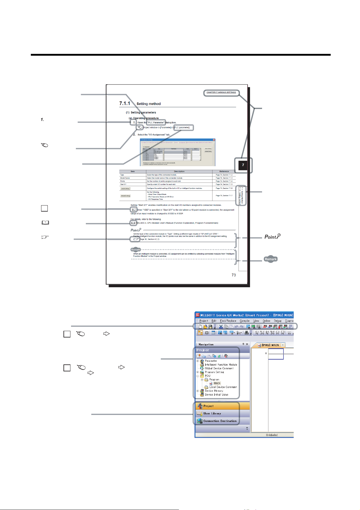
MANUAL PAGE ORGANIZATION
The section of
the current page is shown.
The chapter of
the current page is shown.
"" is used for
screen names and items.
[ ] is used for items
in the menu bar and
the project window.
shows operating
procedures.
shows reference
manuals.
shows notes that
requires attention.
shows mouse
operations.
*1
shows
reference pages.
shows setting or
operating examples.
Ex.
shows useful
information.
In this manual, pages are organized and the symbols are used as shown below.
The following illustration is for explanation purpose only, and should not be referred to as an actual documentation.
*1 The mouse operation example (for GX Works2) is provided below.
Menu bar
Ex.
A window selected in the view selection area is displayed.
Ex.
View selection area
[Online] [Write to PLC...]
Select [Online] on the menu bar,
and then select [Write to PLC...].
Project window
[PLC Parameter]
Select [Project] from the view selection
area to open the Project window.
In the Project window, expand [Parameter] and
select [PLC Parameter].
[Parameter]
17
Page 20

TERMS
Unless otherwise specified, this manual uses the following terms.
Term Description
Address A parameter assigned to a slave module to identify each node on the AnyWireASLINK network
Address writer A hand-held device to read/write parameters (including addresses) from/to a slave module
A system where sensors at the end of a control system are connected to a programmable controller in the most
AnyWireASLINK
AnyWireASLINK bridge module A generic term for the NZ2AW1C2AL and NZ2AW1GFAL
AnyWireASLINK master module A generic term for the RJ51AW12AL, QJ51AW12AL, and LJ51AW12AL
ASLINKAMP A generic term for sensor amplifiers that have an AnyWireASLINK interface
ASLINKER A generic term for I/O devices that have an AnyWireASLINK interface
Buffer memory
CPU module A generic term for the MELSEC-Q and -L series CPU modules
GX Developer
GX Works2
Head module The abbreviation for the LJ72GF15-T2 CC-Link IE Field Network head module
ID
Intelligent function module
Master module A generic term for the QJ51AW12AL and LJ51AW12AL
MELSEC-L series The abbreviation for the Mitsubishi programmable controller MELSEC-L series
MELSEC-Q series The abbreviation for the Mitsubishi programmable controller MELSEC-Q series
Power cable (24V, 0V) A cable that connects a master module to a 24VDC external power supply
Programming tool A generic term for GX Works2 and GX Developer
Slave module A generic term for modules that communicate data with a master module
Terminating unit A waveform shaper
Transmission cable (DP, DN) A signal cable that connects a slave module to a master module
Transmission cycle time A data sampling interval
suitable way.
With this system, a bridge module can detect sensor disconnection and a user can set the I/O operations of a slave
module on a bridge module without using I/O areas of the CPU module.
A memory in an intelligent function module, where data (such as setting values and monitoring values) exchanged
with a CPU module are stored
The product name of the software package for the MELSEC programmable controllers
A parameter to identify whether the module is an input module or output module based on its address
Output slave module ID: Address
Input slave module/I/O combined slave module ID: Address + 200
A MELSEC-Q/L series module that has functions other than input and output, such as an A/D converter module and
D/A converter module
H
18
Page 21
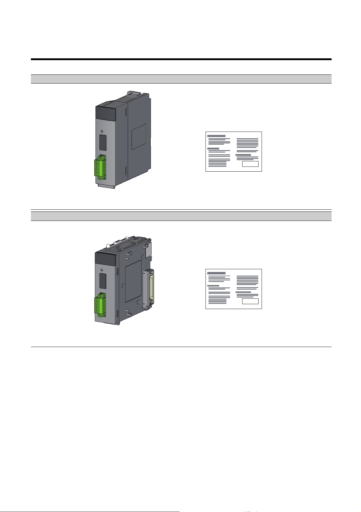
PACKING LIST
QJ51AW12AL Before Using the Product
LJ51AW12AL Before Using the Product
The following items are included in the package of this product. Before use, check that all the items are included.
QJ51AW12AL
LJ51AW12AL
19
Page 22
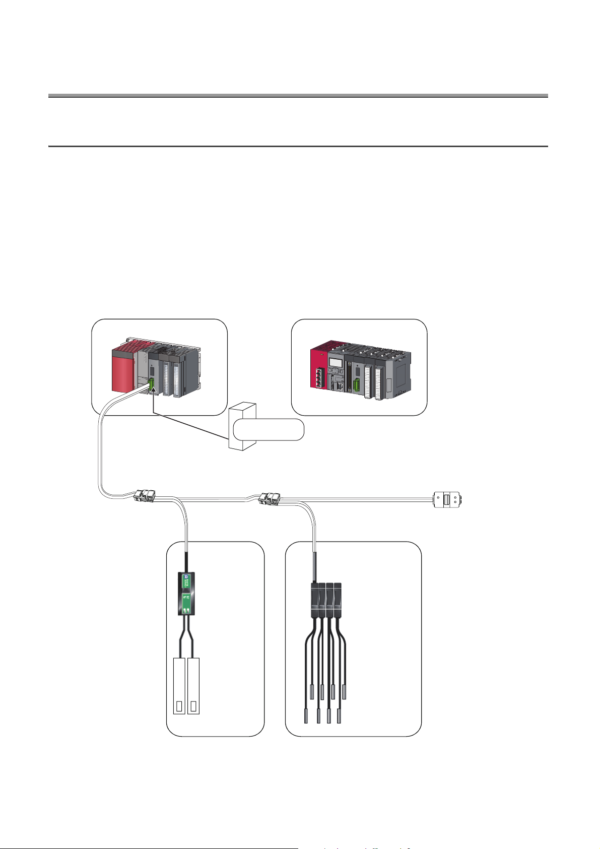
CHAPTER 1 FEATURES
ASLINKER
*1
LJ51AW12AL
ASLINKAMP
*1
24VDC
General-purpose
power supply
QJ51AW12AL
or
Cylinder,
switch, or
others
AnyWireASLINK terminating unit
*1
*
1 Manufactured by Anywire Corporation
Sensor head
1.1 AnyWireASLINK
The AnyWireASLINK is a high-speed and highly reliable system which releases the work site from complicated and
incorrect wiring.
In this network, sensors at the end of a control system are connected to a programmable controller in the optimum
form.
Furthermore, this network enables a mater module to detect sensor disconnection and enables a user to set the
operations of a slave module only using the areas, 32 points occupied, of a master module with the I/O assignment
setting.
The master module, a product of the joint development project with Anywire Corporation, allows the AnyWireASLINK
system to be constructed in a MELSEC-Q or MELSEC-L series programmable controller system.
20
Page 23
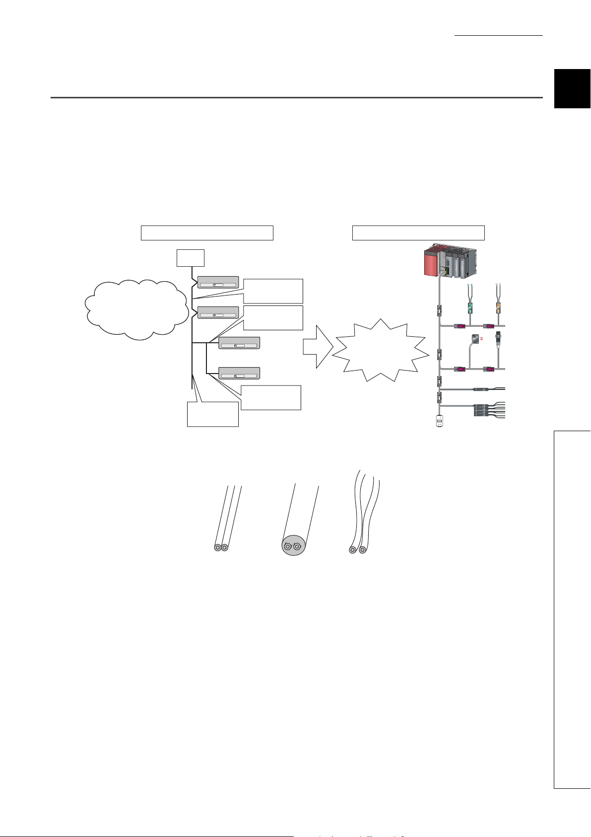
CHAPTER 1 FEATURES
Restricted
station-to-station
distance
Restricted
branch line length
Restricted number
of branches
Restricted main
line length
Standard network
Master
station
AnyWireASLINK
Adding a station to
the existing network is
hard with many
restrictions on wiring.
A station
can be added only
if the total length
is within 200m.
Flat cable
General-purpose
2-wire cable
General-purpose
wire
1.2 Features
This section describes the features of the AnyWireASLINK.
(1) Flexible wiring
The AnyWireASLINK allows flexible connections if the overall cable distance of transmission cables (DP, DN) is
within 200m.
There is no restriction about, for example, the main line length, station-to-station distance, and number of
branches.
1
(2) Single-touch cable connection and disconnection
(3) Space saving
Moreover, because of a little restrictions about cables, cables used for other networks can be used for the
AnyWireASLINK without modification, resulting in reduced wiring man-hours and cable cost.
*1 Before using, check the performance specifications. ( Page 26, Section 3.2.1)
Using a dedicated connector enables cables to be connected and disconnected with a single operation and
eases slave module addition and replacement.
*1 For wiring with the dedicated connectors, contact Anywire Corporation.
The system needs much less space because of a wide selection of small-type slave modules (manufactured by
Anywire Corporation).
*1
*1
1.2 Features
21
Page 24

(4) RAS improvement
The system start-up time can be reduced by checking whether a slave module is connected or by detecting an ID
setting error.
22
Page 25
CHAPTER 2 PART NAMES
2)
3)
3)
6)
4)5) 5)
LJ51AW12AL
1)
5)
5)
This chapter describes the part names of the master module.
QJ51AW12AL
1)
2)
3) 3)
CHAPTER 2 PART NAMES
2
4)
23
Page 26

No. Name Description
The master module status is indicated by the LEDs.
LED name Description
Indicates the operating status of the master module.
RUN LED (green)
LINK LED (green)
1) LED display
SET LED (green)
ALM LED (red)
2) SET switch Switch for automatic detection of the slave module ID (address)
Transmission cable terminal
3)
block
4) Serial number display Displays the serial number printed on the rating plate
5) Module joint lever A lever for connecting modules
6) DIN rail hook A hook for mounting a module to a DIN rail
A terminal block of the AnyWireASLINK
ON: Operating normally
OFF: Master module error, 5VDC power off, or CPU module stop error
Indicates the link status of the master module.
Flashing: Communication is possible.
Off, On: Communication is not possible.
Indicates the address detection status of the master module.
On: Automatic address detection in progress
Flashing: Address write in progress
Off: Before or after automatic address detection
Indicates the alarm status of the master module.
ON: DP/DN disconnection, no response from the slave module
Slow flashing (one-second intervals): DP/DN short
Fast flashing (0.2-second intervals): 24VDC is not being supplied or the
voltage is low.
OFF: Operating normally
24
Page 27

CHAPTER 3 SPECIFICATIONS
CHAPTER 3 SPECIFICATIONS
This chapter describes the general specifications and performance specifications and lists the functions, I/O signals,
and buffer memory addresses.
3.1 General Specifications
For the general specifications of the master module, refer to the following.
"Safety Guidelines" included with the CPU module, base unit, or head module
3
3.1 General Specifications
25
Page 28
3.2 Performance Specifications
3.2.1 Performance list
The following table lists the performance specifications of the master module.
Item
Transmission clock 27.0kHz
Maximum transmission distance (total
length)
Transmission system DC power supply transmission total frame cyclic system
Connection type Bus topology (multidrop system, T-branch system, tree branch system)
Transmission protocol Dedicated protocol (AnyWireASLINK)
Error control Checksum, double-check system
Number of connected I/O points Up to 512 points (256 input points/256 output points)
Number of connectable slave modules Up to 128 (varies depending on the current consumption of each slave module)
RAS function
Transmission cable (DP, DN)
Power cable (24V, 0V)
Transmission cable supply current
Maximum number of writes to EEPROM Up to 100000 times
Internal current
consumption (5VDC)
Power supply
Number of occupied I/O points 32 points (I/O assignment: intelligent 32 points)
External dimensions 98.0mm (H) 27.4mm (W) 100.0mm (D) 90.0mm (H) 28.5mm (W) 104.5mm (D)
Weight 0.2kg
External power
supply
*1
Disconnected transmission cable location detection function, transmission cable short
• UL-listed general-purpose 2-wire cable (VCTF, VCT 1.25, 0.75, temperature rating
70 or higher)
• UL-listed general-purpose wire (1.25, 0.75, temperature rating 70 or higher)
• Dedicated flat cable (1.25, 0.75, temperature rating 90)
• UL-listed general-purpose 2-wire cable (VCTF, VCT 0.75 to 2.0, temperature
rating 70 or higher)
• UL-listed general-purpose wire (0.75 to 2.0, temperature rating 70 or higher)
• Dedicated flat cable (1.25, 0.75, temperature rating 90)
Voltage: 21.6 to 27.6VDC (24VDC -10% to +15%), ripple voltage 0.5Vp-p or lower
QJ51AW12AL LJ51AW12AL
detection function, transmission cable voltage drop detection function
When using a 1.25 cable: Up to 2A
When using a 0.75 cable: Up to 1.2A
Current consumption: Up to 0.2A
Recommended voltage: 26.4VDC (24VDC + 10%)
Module current consumption: 0.1A
Transmission cable supply current: Up to 2A
Model name
*2
200m
Voltage: 5VDC 5%
*1
26
*1 For the relationship between the total length, the wire diameter of transmission cables (DP, DN), and the transmission
cable supply current, refer to the following. On some slave modules with cables, the wire diameter of module-integrated
transmission cables (DP, DN) may be 0.75or less. However, they can be used without any problem, provided that the
diameter of the transmission cables (DP, DN) meets the requirement below.
Wire diameter of
transmission
cables (DP, DN)
1.25 Up to 2A Up to 1A Up to 0.5A
0.75 Up to 1.2A Up to 0.6A Up to 0.3A
Total length of 50m or
*2
less
Transmission cable supply current
Total length of 50m to
*2
100m
Total length of 100m to
200m
*2
Page 29

CHAPTER 3 SPECIFICATIONS
*2 For slave modules with integrated transmission cables (DP, DN), the length of the transmission cables (DP, DN) is
included in the total length.
For wiring of 50m or more with 4 wires (DP, DN, 24V, 0V), insert the noise filter for power supply cables between the
power supply and cables. For details, refer to the manual for the AnyWireFILTER (ANF-01) manufactured by Anywire
Corporation.
3
3.2.1 Performance list
3.2 Performance Specifications
27
Page 30
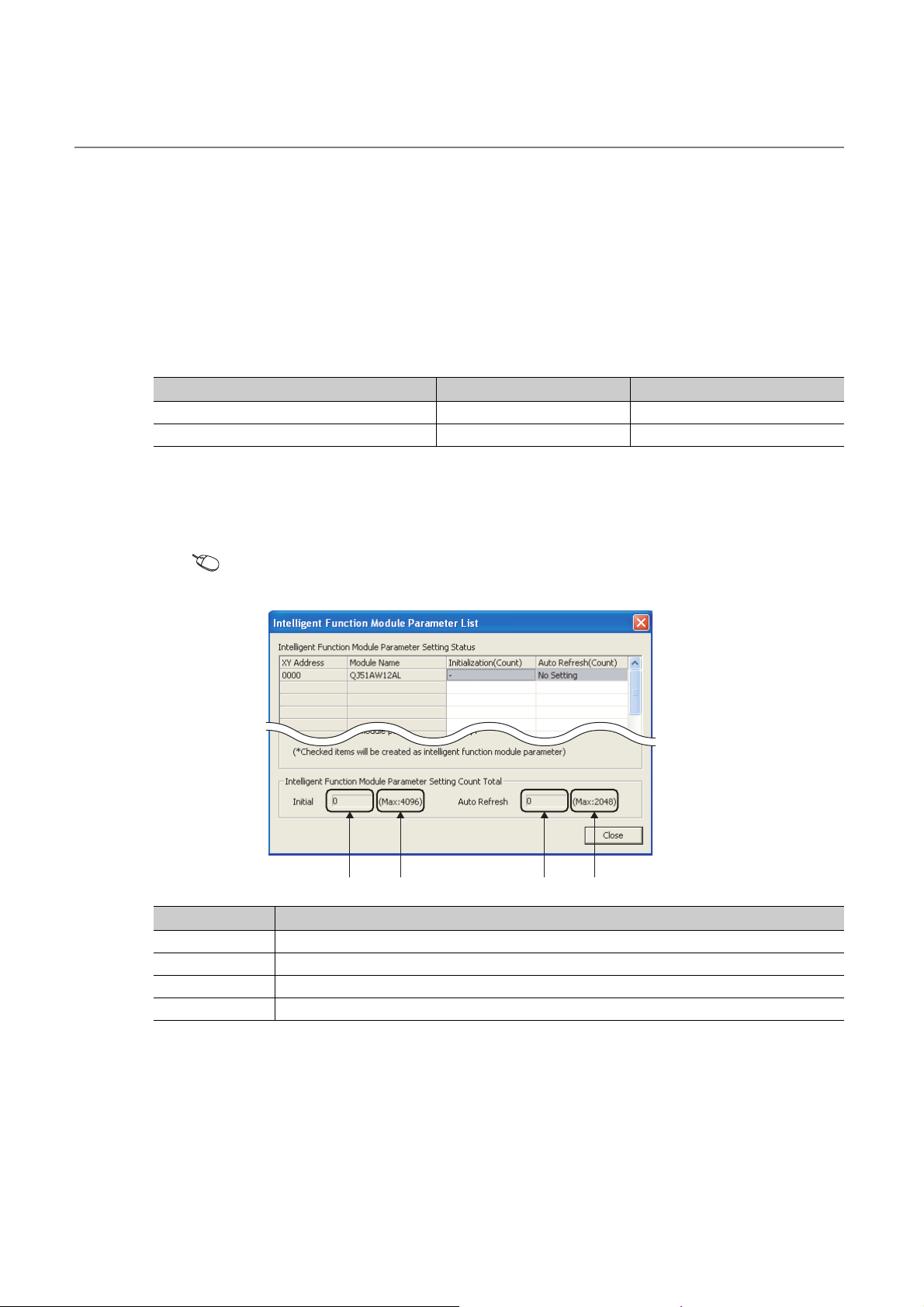
3.2.2 Number of parameters to set
1) 2) 3) 4)
As for the initial settings of a master module and the parameter settings regarding the auto refresh setting, do not set
the number of parameters, including those of other intelligent function modules, greater than the number of parameters
that can be set in a CPU module.
For the maximum number of parameters settable on the CPU module, refer to the following.
User's Manual (Hardware Design, Maintenance and Inspection) for the CPU module used
MELSEC-L CC-Link IE Field Network Head Module User's Manual
(1) The number of parameters for a master module
The master module allows the following number of parameters per module.
Target module Initial setting Auto refresh setting
QJ51AW12AL 0 (unused) 2 (maximum number of settings)
LJ51AW12AL 0 (unused) 2 (maximum number of settings)
(2) Check method
The number of parameters set in an intelligent function module and the maximum number of parameter settings
can be checked with the following operations:
Project window [Intelligent Function Module] Right click
[Intelligent Function Module Parameter List]
No. Description
1) Total number of initial setting parameters having the checkboxes checked on the window
2) Maximum number of initial parameter settings
3) Total number of auto refresh setting parameters having the checkboxes checked on the window
4) Maximum number of auto refresh setting parameters
28
Page 31

3.2.3 Communication performance
Remark
Minimum data
response time
Input data change
Input data change
Input data update
Input data update
Maximum data
response time
Sampling timing Sampling timing Sampling timing
Minimum one-transmission cycle time
Maximum two-transmission cycle time
Sampling timing Sampling timing
(1) Transmission cycle time
The transmission cycle time is the time required for the master module and all the slave modules to update I/O
data.
The transmission cycle time of the master module is listed in the table below.
Number of
transmission points
One transmission
cycle time
● The transmission delay time is a value between one- and two-transmission cycle time.
● To ensure the response to the input signal, provide an input signal that is longer than two-transmission cycle time.
64 points (32 input
points, 32 output
points)
2.3ms 3.5ms 5.9ms 10.6ms
128 points (64 input
points, 64 output
points)
CHAPTER 3 SPECIFICATIONS
256 points (128 input
points, 128 output points)
512 points (256 input
points, 256 output points)
3
(2) Effects of the double check system
(a) Input
Unless the same data is received twice successively on the master module side, the input area data is not
updated.
A minimum of one-transmission cycle time and a maximum of two-transmission cycle time are required as the
data response time.
Therefore, when an input signal is shorter than two-transmission cycle time, the input data may not be captured
depending on the timing.
To ensure the response, provide an input signal that is longer than two-transmission cycle time.
(b) Output
As the double check is performed on the slave module side, the time required is the same as that for input,
namely a minimum of one-transmission cycle time and a maximum of two-transmission cycle time.
3.2 Performance Specifications
3.2.3 Communication performance
29
Page 32

(3) Response delay time
Input
Slave module
AnyWireASLINK
CPU module
3) Transmission time
4) Processing time on the
master module
1) Input response time on the
slave module
2) Processing time on the
slave module
5) Processing time on the
programmable controller
The following shows the response delay time of input and output.
(a) Input response delay time
The figure below shows the time between a signal input to the slave module and the CPU module device
turning on/off.
The input response delay time is the total of 1) to 5) in the following figure.
No. Description Required time
1) Input response time on the slave module
2) Processing time on the slave module
3) Transmission time
4) Processing time on the master module 0.6ms
5)
Processing time on the programmable
controller
Refer to the manual for the slave module connected to the
system or the device connected to the slave module.
Approx. 0.2ms (The time differs depending on the slave
module.)
Transmission cycle time 2
The transmission cycle time differs depending on the number
of transmission points. ( Page 29, Section 3.2.3 (1))
Sequence scan time 2
30
Page 33

CHAPTER 3 SPECIFICATIONS
Output
(b) Output response delay time
The figure below shows the time between the CPU module device turning on/off and a signal output from the
slave module turning on/off.
The output response delay time is the total of 1) to 5) in the following figure.
Output
Slave module
5) Output response time
on the slave module
4) Processing time on the
slave module
Output
3
AnyWireASLINK
CPU module
1) Processing time on the
programmable controller
3) Transmission time
2) Processing time on the
master module
No. Description Required time
1)
2) Processing time on the master module 0.6ms
3) Transmission time
4) Processing time on the slave module
5) Output response time on the slave module
Processing time on the programmable
controller
Sequence scan time
Transmission cycle time 2
The transmission cycle time differs depending on the number
of transmission points. ( Page 29, Section 3.2.3 (1))
Approx. 0.04ms (The time differs depending on the slave
module.)
Refer to the manual for the slave module connected to the
system or the device connected to the slave module.
(4) Parameter access response time
The parameters of the AnyWireASLINK provide the monitoring information of the slave module or the entire
system and the setting information of the slave module.
Parameter data are synchronized between the buffer memory of the master module and the slave module at a
cycle different from that of the I/O data.
Use the following calculation formulas to obtain the parameter access response time.
3.2 Performance Specifications
3.2.3 Communication performance
[Update interval time of an automatically updated parameter]
Number of AnyWireASLINK connection IDs transmission cycle time 3
[Time required for reading a parameter]
Number of target IDs transmission cycle time 27
[Time required for writing a parameter]
Number of target IDs transmission cycle time 39
31
Page 34

3.3 Function List
The following table lists the functions of the master module.
Item Description Reference item
Bit transmission function
Parameter reading function
Parameter writing function
Automatic address detection function
Transmission cable short detection
function
Disconnected transmission cable
location detection function
Transmission cable voltage drop
detection function
Parameter access error detection
function
Same ID used detection function
Module with no ID setting detection
function
Backup/restoring function
Performs input and output of up to 512 points (256 input points and 256
output points) between the master module and the slave module.
Reads the parameters of a slave module connected to the master module
without delaying the AnyWireASLINK bit transmission.
Writes the parameters of a slave module connected to the master module
without delaying the AnyWireASLINK bit transmission.
The master module detects or stores the ID (address) of the connected
slave module when the SET switch on the front of the master module is
pressed. (Alternatively a specific bit can be used.)
Detects a short in DP-DN cables. Page 62, Section 8.2
Detects the location of DP-DN cable disconnection. Page 63, Section 8.3
Monitors a voltage drop in the 24VDC external power supply. Page 64, Section 8.4
Detects an error upon reading or writing of the setting values of the slave
module.
Checks whether the same ID is used for multiple slave modules. The
LEDs of the relevant slave modules are forcibly turned on.
Detects slave modules with no ID assigned (default ID). Page 68, Section 8.7
Backs up various information of the connected slave module into the SD
memory card of the CPU module.
Restores the information backed up on the SD memory card of the CPU
module into the connected slave module.
Page 62, Section 8.1
Page 69, Section 8.8
Page 69, Section 8.8
Page 57, Section 7.3
Page 65, Section 8.5
Page 67, Section 8.6
Page 74, Section 8.9
32
Page 35

CHAPTER 3 SPECIFICATIONS
3.4 List of I/O Signals
The following table lists the signals input or output between the CPU module and the master module.
For details on the I/O signals, refer to Page 101, Appendix 1.
Signal direction: Master module to CPU module Signal direction: CPU module to master module
Device number Signal name Device number Signal name
Xn0 Module READY Yn0 Error flag clear command
Xn1 DP/DN short error Yn1
Xn2 Use prohibited
Xn3
Xn4 DP/DN disconnection error
Xn5 to XnF Use prohibited
X(n+1)0 Slave module alarm signal Y(n+1)0
X(n+1)1
X(n+1)2 Parameter access error Y(n+1)2
X(n+1)3 Use prohibited
X(n+1)5 to X(n+1)F Use prohibited
Transmission cable voltage drop
error
Parameter access completion
flag
Y(n+1)3 to Y(n+1)F Use prohibitedX(n+1)4 Automatic address detection flag
Yn2 to YnF Use prohibited
Y(n+1)1
Automatic address detection
command
Parameter access request
command for the slave module
Parameter batch read command
for the slave module
Parameter batch write command
for the slave module
3
3.4 List of I/O Signals
33
Page 36

3.5 List of Buffer Memory Addresses
Buffer memory is for data communications between the master module and the CPU module.
When the CPU module is reset or the system is powered off and on, the data in the buffer memory are set back to the
default (initial values).
The following table lists the buffer memory addresses for the master module.
For details on the buffer memory, refer to Page 104, Appendix 2.
Buffer memory address
Decimal Hexadecimal
to F
0 to 15
16 to 4095
4096 to 4111
4112 to 8191
8192
8193 to 8320
8321 to 8959
8960
8961 to 9215
9216
9217 to 9344
9345 to 9983
9984
9985 to 10112
10113 to 10255
10256
10257
10258 to 10319
10320
10321
10322 to 10495
10496 to 10751
10752 to 11007
11008 to 11263
11264 to 12287
12288 to 18431
18432 to 32767
0
H
10
H
1000
1010
2000
2001
2081
2300
2301
2400
2401
2481
2700
2701
2781
2810
2811
2812
2850
2851
2852
2900
2A00
2B00
2C00
3000
4800
to FFF
H
H
H
H
H
H
H
H
H
H
H
H
H
H
H
H
H
H
H
H
H
H
H
H
H
to 100F
to 1FFF
to 2080
to 22FF
to 23FF
to 2480
to 26FF
to 2780
to 280F
to 284F
to 28FF
to 29FF
to 2AFF
to 2BFF
to 2FFF
H
to 47FF
to 7FFF
Item
Input information area Read only
H
H
H
H
H
Number of the connected modules Read only
H
Number of the IDs of the connected modules Read only
H
H
H
H
H
Connected module ID information storage area Read only
Parameter access target module ID specification Read and write
H
H
H
H
H
H
H
Parameter storage location memory number (output) Read only
Parameter storage location memory number (input) Read only
System reserved
Output information area Read and write
System reserved
Number of the error IDs Read only
Error ID information storage area Read only
System reserved
System reserved
System reserved
Number of the alarm IDs Read only
Alarm ID information storage area Read only
System reserved
Latest error code storage area Read only
Latest error ID storage area Read only
System reserved
Parameter access setting Read and write
System reserved
System reserved
System reserved
Parameter storage area Read and write
System reserved
Allowable
operation
(Read/write)
34
If data are written in the system reserved area, it may cause malfunction of the programmable controller system.
Page 37

CHAPTER 4 PROCEDURES BEFORE OPERATION
Start
Checkbox
Master module mounting/connecting
Mount or connect the master module.
Slave module installation
Install the slave module in the control panel or machine.
Wiring
Connect each module using transmission lines (DP, DN) and power
cables (24V, 0V).
System power-on
Check the following before powering on the system:
Whether the master module is properly mounted or connected
Proper voltage supply to the power supply module of the programmable
controller and 24V and 0V terminals of the master module
Whether the switch on the CPU module is set to STOP
Whether each module is properly wired
Transmission distance
Set the address of the slave module.
Address setting
CHAPTER 4 PROCEDURES BEFORE OPERATION
This chapter describes the procedure from module mounting/connecting to system operation.
MELSEC-L CC-Link IE Field
User's manual for the slave
Page 43, Section 6.2
User's Manual (Hardware
Design, Maintenance and
Inspection) for the CPU
module used
Network Head Module User's
Manual
module used (manufactured by
Anywire Corporation)
4
Page 51, Section 6.4
Page 55, Section 7.2
35
Page 38

Operation mode setting for the master module
Set the number of transmission points for the master module.
Automatic address detection
Save the address of the slave module in the EEPROM of the master
module.
Page 53, Section 7.1
Page 57, Section 7.3
Parameter setting
Set the parameters of the slave module.
System operation
Operate the system.
End
Page 69, Section 8.8
36
Page 39

CHAPTER 5 SYSTEM CONFIGURATION
Master module
Power supply module
CPU module
Power supply module CPU module Master module
Display unit
(optional)
END cover
CHAPTER 5 SYSTEM CONFIGURATION
This chapter describes the overall configuration, system configuration of the master module, system configuration of
AnyWireASLINK, and applicable systems.
5.1 Overall Configuration
5.1.1 System configuration of the master module
This section describes the system configuration of the master module.
(1) QJ51AW12AL
The following system configuration of the QJ51AW12AL is used for explanation purpose.
(2) LJ51AW12AL
The following system configurations of the LJ51AW12AL are used for explanation purpose.
(a) When connected to the CPU module
5
5.1 Overall Configuration
5.1.1 System configuration of the master module
37
Page 40

(b) When connected to the head module
Power supply module CPU module Master module END cover
38
Page 41

CHAPTER 5 SYSTEM CONFIGURATION
ASLINKER
*1
LJ51AW12AL
ASLINKAMP
*1
24VDC
General-purpose
power supply
QJ51AW12AL
or
Cylinder,
switch, or
others
AnyWireASLINK terminating unit
*1
*
1 Manufactured by Anywire Corporation
Sensor head
5.1.2 System configuration of AnyWireASLINK
The following figure shows the system configuration of AnyWireASLINK.
5
For the number of connectable slave modules, refer to the following.
Page 26, Section 3.2.1
5.1 Overall Configuration
5.1.2 System configuration of AnyWireASLINK
39
Page 42

5.2 Applicable Systems
Remark
This section describes applicable systems.
5.2.1 QJ51AW12AL
(1) Applicable modules and base units, and the number of connectable modules
(a) Connecting a QJ51AW12AL to a CPU module
For the CPU modules, the number of modules, and base units applicable to the QJ51AW12AL, refer to the
user's manual for the CPU module used.
Note the following when the QJ51AW12AL is used with a CPU module.
• Depending on the combination with other modules or the number of mounted modules, power supply
capacity may be insufficient. Pay attention to the power supply capacity before mounting modules, and if
the power supply capacity is insufficient, change the combination of the modules.
• Mount a module within the number of I/O points for the CPU module. If the number of slots is within the
available range, the module can be mounted on any slot.
When using a C Controller module, refer to the user's manual for the C Controller module.
(b) Connecting a QJ51AW12AL in a MELSECNET/H remote I/O station
For the MELSECNET/H remote I/O station, the number of modules, and base units applicable to the
QJ51AW12AL, refer to the Q Corresponding MELSECNET/H Network System Reference Manual (Remote I/O
network).
(c) Connecting the QJ51AW12AL to an RQ extension base unit
When connecting the QJ51AW12AL to an RQ extension base unit, refer to the MELSEC iQ-R Module
Configuration Manual.
(2) Compatibility with a multiple CPU system
The QJ51AW12AL is compatible with a multiple CPU system from the first product.
When using the QJ51AW12AL in a multiple CPU system, refer to the following.
QCPU User's Manual (Multiple CPU System)
(3) Online module change
The QJ51AW12AL does not support online module change.
40
Page 43

5.2.2 LJ51AW12AL
(1) Number of connectable modules
For the number of connectable modules, refer to the following.
MELSEC-L CPU Module User's Manual (Hardware Design, Maintenance and Inspection)
MELSEC-L CC-Link IE Field Network Head Module User's Manual
(2) Precautions for the system configuration
(a) Rated output current (5VDC)
The total current consumption upon system configuration must not exceed the rated output current (5VDC) of
the power supply module of the programmable controller. For the specifications of the power supply module,
refer to the following.
MELSEC-L CPU Module User's Manual (Hardware Design, Maintenance and Inspection)
CHAPTER 5 SYSTEM CONFIGURATION
5
5.2 Applicable Systems
5.2.2 LJ51AW12AL
41
Page 44

5.3 Compatible Software Version
The system which uses a master module is compatible with the software package as follows.
A programming tool is required when a master module is used.
Software Version
GX Works2 Version 1.98C or later
42
Page 45

CHAPTER 6 INSTALLATION AND WIRING
CHAPTER 6 INSTALLATION AND WIRING
This chapter describes the installation and wiring of the master module.
6.1 Installation Environment and Position of the Master
Module
For the precautions for the installation environment and position of the master module, refer to the following.
User's Manual (Hardware Design, Maintenance and Inspection) for the CPU module used
MELSEC-L CC-Link IE Field Network Head Module User's Manual
6.2 Wiring
(1) Descriptions of terminals
6
Terminal Description
24V
0V
DP AnyWireASLINK transmission signal terminals
DN
LG
Power supply terminal for driving the transmission circuit for the AnyWireASLINK system.
Connect to a 24VDC external power supply.
DP: Transmission cable (+), DN: Transmission cable (-)
Connect to the DP and DN terminals on the slave module or terminating unit.
Connected to the neutral point of the noise filter inserted between the 24V and 0V terminals.
Ground the LG terminal with the functional ground terminal (FG terminal) on the programmable
controller at a single point.
6.1 Installation Environment and Position of the Master Module
43
Page 46

(2) Transmission cable terminal block
Model name Applicable tightening torque
MC 1,5/5-STF-3,81
*1 Use the one manufactured by PHOENIX CONTACT GmbH & Co. KG. (For contact, visit www.phoenixcontact.com.)
*1
Classification Name Wire diameter Type Material
UL-listed general-purpose 2-wire
cable (VCTF, VCT)
Transmission
cable (DP, DN)
Power supply
cable (24V, 0V)
UL-listed general-purpose wire
Dedicated flat cable
UL-listed general-purpose 2-wire
cable (VCTF, VCT)
UL-listed general-purpose wire 0.75 to 2.0
Dedicated flat cable
0.2Nm to 0.3Nm
1.25
0.75
1.25
0.75
1.25
0.75
0.75 to 2.0 Stranded wire
1.25
0.75
Stranded wire
Stranded
wire/single
wire
Stranded wire 90
Copper
wire
Temperature
rating
70 or higher
90
70 or higher
To tighten the terminal block, a flathead screwdriver having a tipped size of 0.4 2.5mm is required.
Before removing the transmission cable terminal block, check that the terminal block mounting screws on both
ends are completely loosened (removed from the socket).
Pulling the terminal block with excessive force while the terminal block mounting screws on both ends are still
tightened may damage the devices.
Before connecting the terminal block, check that there are no short-circuits due to the disconnected or frayed
wires and tighten the terminal block mounting screws at both ends securely. (Tightening torque: 0.2 to 0.3Nm)
(3) Cable processing
Bare cables can be connected to the transmission cable terminal block; however, for safety reasons, it is
recommended to connect cables using bar solderless terminals.
Use UL-listed solderless terminals and, for processing, use a tool recommended by their manufacturer.
Typ e Model name
Bar
solderless
terminal
*1 When connecting two cables to one terminal, connect the two cables together to the TWIN bar solderless terminal.
*2 When TWIN bar solderless terminals are used, the maximum wire diameter is 0.75.
AI 0,75-8 GY Processing of a 0.752 wire
AI 1,5-8 BK Processing of a 1.252 wire
*1
AI-TWIN 2 0,75-8 GY Processing of two 0.75 wires
Application
*2
PHOENIX CONTACT GmbH & Co. KG
(www.phoenixcontact.com)
Contact
44
Page 47

6.2.1 Wiring precautions
The following shows the wiring precautions in the AnyWireASLINK system.
• In the AnyWireASLINK system, signals and power are supplied to a slave module with two types of
transmission cables; DP and DN. Therefore, using a stranded wire of 1.25 or larger for the main line is
recommended.
• Wires such as general-purpose wires, cabtyre cables, and flat cables can be used.
• Do not run multiple transmission cables (DP, DN) using a multicore cable. Running multiple transmission
cables (DP, DN) together may cause noise, resulting in a malfunction.
CHAPTER 6 INSTALLATION AND WIRING
DP
DN
DP
DN
• The voltage should not fall below the lower limit of the allowable voltage range due to the voltage drop
caused by the cable. If the voltage falls below the lower limit, malfunctions may occur.
• Do not connect soldered cables directly to the terminals. Doing so may loosen the screws, resulting in a poor
contact.
• Use a crimping tool to connect a cable to a bar solderless terminal.
• Before inserting a bar solderless terminal, check the shapes of the wire insertion opening and bar solderless
terminal. Then, insert the terminal in the correct orientation. Inserting a bar solderless terminal wider than the
wire insertion opening may damage the terminal block. ( Page 44, Section 6.2 (3))
DP
DN
DP
DN
6
6.2.1 Wiring precautions
6.2 Wiring
45
Page 48

6.2.2 Connection of slave modules
Master module
A
Terminating
unit
Slave
module
Slave
module
Slave
module
Slave
module
C
B
Tree-type T-branch
Multidrop
(1) Connection type
• The maximum transmission distance in the AnyWireASLINK stand-alone system is 200m, which is the total
cable length including the main line and branch line (branch). (It varies depending on the wire diameter of
the transmission cables (DP, DN) or the transmission cable supply current.)
• Tree branch, T-branch, and multidrop connections are usable in the AnyWireASLINK system.
• Up to 128 slave modules can be connected.
The total length of the transmission distance for the AnyWireASLINK system can be calculated from A + B + C.
Note that the total length should not exceed the maximum transmission distance or the total length set for the system to
branch lines.
46
Page 49

CHAPTER 6 INSTALLATION AND WIRING
6.2.3 Power supply to the AnyWireASLINK system
(1) Method of supplying the power to the slave module
Connect a 24VDC external power supply to the master module.
The power consumed in the internal control circuits of all the slave modules and the external load power
connected to non-isolated slave modules are supplied collectively from the 24VDC external power supply
connected to the master modules.
( Page 26, Section 3.2)
(2) Scope of the power supply with transmission cables (DP and DN)
The current consumption of the system must satisfy all the conditions specified by the following calculation
formulas 1) to 3) for each master module.
Condition Calculation formula Description
Ihin: Current consumption of the non-isolated input slave module/I/O combined slave
module
Iho: Current consumption of the non-isolated output slave module
Izdin: Current consumption of the isolated input slave module/I/O combined slave
module
I(A) = (Ihin x m) + (Iho x n) + (Izdin x
1)
p) + (Izdo x q) The maximum value
of transmission cable supply current
Izdo: Current consumption of the isolated output slave module
m: Number of connected non-isolated input slave modules/I/O combined slave
modules
n: Number of connected non-isolated output slave modules
p: Number of connected isolated input slave modules/I/O combined slave modules
q: Number of connected isolated output slave modules
6
For details, refer to Page 48, Section 6.2.3 (2) (a).
2)
3)
Vm(V) - V(V) 20V
Vm(V) - V(V) The lowest
allowable voltage of the connected
load
Vm: Supply voltage for the master module
V: Cable-to-cable voltage drop
For details, refer to Page 50, Section 6.2.3 (2) (b).
6.2.3 Power supply to the AnyWireASLINK system
6.2 Wiring
47
Page 50

(a) Description of the condition 1)
Non-isolated slave module
Control circuit
Power supply
generation
Connected load
24VDC external
power supply
24V 0V
24V 0V
24VL 0VL 01 n
DP DN
DP DN
Master module
• Constants related to the non-isolated slave module (Ihin, Iho)
For the non-isolated slave module, the current required for the internal control circuit and the connected
load is supplied over transmission cables (DP, DN).
Ihin(A) = Current consumption of the non-isolated input slave module/I/O combined slave module
= Current consumption of the non-isolated input slave module/I/O combined slave module +
Current consumption of connected load (three-wire sensor) Number of points
Iho(A)
= Current consumption of the non-isolated output slave module
= Current consumption of the non-isolated output slave module + Current consumption of
connected load Number of points
48
● The 24VL and 0VL terminals of a slave module are used to supply the power to the connected load.
● For the current consumption of a non-isolated slave module, refer to the manual for the slave module used.
Page 51

CHAPTER 6 INSTALLATION AND WIRING
Isolated slave module
Control circuit
Load driving circuit (photocoupler)
Connected load
24VDC external
power supply
24VDC external
power supply
24V 0V
24V 0V
24VL 0VL
24V 0V
01 n
DP DN
DP DN
Master module
• Constants related to the isolated slave module (Izdin, Izdo)
For the isolated slave module, only the current required for the internal control circuit is supplied over the
transmission cables (DP, DN), whereas that for the connected load is supplied from the 24VDC external
power supply.
Izdin(A) = Internal current consumption of the isolated input slave module/I/O combined slave module
Izdo(A) = Internal current consumption of the isolated output slave module
6
● In isolated type slave modules, the current consumption of the connected load is not subject to the current restriction
condition for the AnyWireASLINK system.
● For the current consumption of isolated slave modules, refer to the manual for the slave module used.
• Transmission cable supply current (I(A))
The transmission cable supply current in the AnyWireASLINK system is determined by the following
formula.
I(A) = (Ihin m) + (Iho n) + (Izdin p) + (Izdo q)
• Maximum transmission cable supply current
For the maximum transmission cable supply current, refer to Page 26, Section 3.2.
Number of connectable modules: m, n, p, q
6.2.3 Power supply to the AnyWireASLINK system
6.2 Wiring
49
Page 52

(b) Description of the conditions 2) and 3)
• Vm: Supply voltage for the master module
Voltage 21.6 to 27.6VDC (24VDC -10% to +15%), ripple voltage 0.5Vp-p or lower
Recommended voltage 26.4VDC (24VDC +10%)
• V(V): Cable-to-cable voltage drop
V(V) = Transmission cable supply current I(A) Cable resistance R()
Cable resistance R() = Cable length (m) Conductor resistance (/m) 2
Wire diameter 1.25 Conductor resistance 0.015/m
Wire diameter 0.75 Conductor resistance 0.025/m
(c) Calculation example
The example shows how to check whether the total length of 100m is sufficient to configure a system in the
following conditions.
[Condition]
• Non-isolated slave module (Input ASLINKER)
Number of I/O points 2 points
Module current
consumption
Number of modules 24
15mA
• Connected load (three-wire sensor)
Three-wire sensor
current consumption
Number of sensors 2
Power supply voltage 24VDC 10%
• Wire diameter of transmission cables (DP, DN)
Wire diameter 1.25
• Power supply for the master module
Power supply voltage 24VDC
[Calculation result]
Condition 1)
Condition 2)
Condition 3)
(Ihin(A) m) = I(A) The maximum transmission cable supply current
(0.015 + (0.013 2)) 24 = 0.984A 1A
Vm(V) - V(V) 20V
24 - (0.984 100 0.015 2) = 24 - 2.95 = 21.05V 20V
Vm(V) - V(V) The lowest limit of the allowable voltage range for
connected load
The lowest limit of the allowable voltage range for connected load = 24
- 24 0.1 = 21.6V
21.05V < 21.6V
13mA
Satisfied
Satisfied
Not satisfied
50
The calculation results 1) to 3) above show that no system can be configured.
However, a system can be configured by changing the power supply for the master module to 24.55VDC or
higher.
Page 53

6.3 Check before Power-on
24VDC external power supply
Module READY(Xn0)
ON
OFF
ON
OFF
ON
OFF
Sequence program
1 second
or longer
Power supply of the
programmable controller
This section describes the items to be checked before power-on.
1. Check that the master module is mounted or connected correctly.
( User's Manual (Hardware Design, Maintenance and Inspection) for the CPU module used)
( MELSEC-L CC-Link IE Field Network Head Module User's Manual)
2. Check that the RUN/STOP/RESET switch
3. Check that the total length of the AnyWireASLINK system is within the specified range. ( Page
26, Section 3.2)
4. Check that the power supplied to the AnyWireASLINK system is within the specified range. (
Page 47, Section 6.2.3)
5. Check that the master module, slave module, terminating unit, and 24VDC external power supply
are properly connected and wired.
CHAPTER 6 INSTALLATION AND WIRING
*1
of the CPU module is set to STOP.
*1 Some CPU modules have a RUN/STOP switch.
6.4 Power-on
After checking the items described above, power on and start the system.
The following is how the AnyWireASLINK system is powered on.
The order is inverted when the system is powered off.
24VDC external power supply for the AnyWireASLINK system Power supply of the programmable controller
6
6.3 Check before Power-on
● If the programmable controller is powered on before the 24VDC external power supply in the AnyWireASLINK system, a
transmission cable voltage drop detection error may occur.
● After turning on Module READY (Xn0), wait at least one second to start the program.
51
Page 54

6.5 Terminating Unit
Terminating unit
Master module
Master module
Important
Important
A
B
Basic
Basic
Connect at least one terminating unit for one AnyWireASLINK line. Connect it at the farthest end from the master module.
Connect one terminating unit at the end of a branch line that exceeds 40m.
[Example]
AnyWire
at the end
Branch line: 40m or longer
The total length of the transmission distance for the AnyWireASLINK system can be calculated from A + B.
Note that the total length should not exceed the maximum transmission distance set for the system to branch lines.
Main line
Main line
The end of a line
Terminating unit connection
Branch of transmission cables (DP, DN)
Total length
Terminating unit
The end of a line
Terminating unit
To ensure more stable transmission quality, connect a terminating unit to the end of a transmission cable (DP, DN).
52
Page 55

CHAPTER 7 VARIOUS SETTINGS
7.1 Master Module Operation Mode Setting
Set the number of transmission points of the master module.
● Making switch settings in Page 54, Section 7.1.2 enables the number of transmission points to be changed and allows
the transmission cycle time to be shorten in comparison with that of the default setting. ( Page 29, Section 3.2.3 (1))
● The switch settings made become effective when the CPU module is reset or the power is turned off then on again after
writing to the CPU module is finished.
7.1.1 Master module addition
CHAPTER 7 VARIOUS SETTINGS
Add the model name of the master module to be used on the project.
(1) Addition method
Open the "New Module" window to add.
Project window [Intelligent Function Module] Right click [New Module]
Item Description
Module Selection
Mount Position
Title setting Title Set a title.
Module Type Set the "AnyWireASLINK Interface Module".
Module Name Set the module name to be connected.
Mounted Slot No. Set the slot No. where the target module is mounted.
The start I/O number (hexadecimal) of the target module
Specify start XY address
corresponding to "Mounted Slot No." has been set. A different address
can be also set.
7.1.1 Master module addition
7
7.1 Master Module Operation Mode Setting
53
Page 56

7.1.2 Switch setting
(1) Setting method
Open the "Switch Setting" window to make the setting.
Project window [Intelligent Function Module] Module name [Switch Setting]
Item Setting value Description
Number of
transmission points
setting
64 Points (input: 32 points, output: 32 points)
128 Points (input: 64 points, output: 64 points)
256 Points (input: 128 point, output: 128 points)
512 Points (input: 256 points, output: 256 points)
Set the number of transmission points.
One transmission cycle time is determined by
setting the number of transmission points. (
Page 29, Section 3.2.3 (1))
7.1.3 Auto refresh
Data in the buffer memory is transferred to a specified device.
With this setting, reading data with a program is not required.
(1) Setting method
Open the "Auto Refresh" window.
1. Start "Auto Refresh" on the project window.
Project window [Intelligent Function Module] Module name [Auto Refresh]
2. Click the item to set. Then enter the device where auto refresh is performed.
54
Page 57

CHAPTER 7 VARIOUS SETTINGS
Address setting port
Infrared
light
Light emitting/
receiving part
Image of address reading/writing
7.2 Slave Module Address Setting
Setting the start number of the addresses assigned for data communications is required for slave modules.
An address can be written to a slave module or the address assigned to a slave module can be read through infrared
communications using an address writer (manufactured by Anywire Corporation).
For details, refer to the manual of the address writer used.
(1) Address setting example
When 0 is set for the input slave module address, and 0 and 2 are set for the output slave module address, bits
are occupied as follows.
Buffer memory address of the input slave module
Buffer memory address
Un\G0
Buffer memory address of the output slave module
Buffer memory address
Un\G4096
Bit No.
15 14 13 12 11 10 9 8 7 6 5 4 3 2 1 0
15 14 13 12 11 10 9 8 7 6 5 4 3 2 1 0
Bit No.
15 14 13 12 11 10 9 8 7 6 5 4 3 2 1 0
15 14 13 12 11 10 9 8 7 6 5 4 3 2 1 0
Occupied
area by the
address 2
Occupied
area by the
address 0
Occupied
area by the
address 0
7
7.2 Slave Module Address Setting
55
Page 58

● A slave module address is not deleted even when the power supply of a programmable controller or a 24VDC external
power supply is turned off. The address is retained until a new address is set when a system is configured.
● For the address setting, ensure that the address occupied by the slave module does not exceed the number of
transmission points set in the master module. For the operation mode setting of the master module, refer to Page 54,
Section 7.1.2.
● In the slave module, a value between 0 and 254 can be written. (This is not an ID value.) Note that 255 cannot be set.
Doing so may cause a No ID setting error.
Model Address (decimal) ID (hexadecimal) ID (decimal)
to 00FE
Output slave module 0 to 254
Input slave module or I/O
combined slave module
0 to 254
0000
0200
H
to 02FE
H
H
H
0 to 254
512 to 766
56
Page 59

CHAPTER 7 VARIOUS SETTINGS
7.3 Automatic Address Detection Function
Automatic address detection is a function to store the IDs (addresses) of the connected slave modules in the EEPROM
of the master module.
The parameters of the connected devices are automatically updated after storage in EEPROM of the master module
followed by detection of IDs (addresses) not set and the same IDs (addresses).
The ID (address) information stored in the EEPROM is held even when the power is turned off. However, information
about unset IDs and the same IDs and the parameter information of each slave module are not held.
Whenever starting the system or changing the system configuration, set the correct addresses to all the slave modules
and perform the automatic address detection.
7.3.1 Performing the automatic address detection
To perform the automatic address detection, use the SET switch or Automatic address detection command (Yn1).
(1) Using the SET switch
1. Check that all of the slave modules are operating normally.
2. Keep pressing the SET switch on the master module until the SET LED (green) turns on.
(At this time, Automatic address detection flag (X(n+1)4) turns on.)
3. When the SET LED flashes for a while and turns off, the ID (address) has been stored.
4. When Automatic address detection flag (X(n+1)4) turns off, automatic address detection is
completed.
(2) Using Automatic address detection command (Yn1)
1. Check that all of the slave modules are operating normally.
2. Turn on and off Automatic address detection command (Yn1). ( Page 33, Section 3.4)
(At this time, Automatic address detection flag (X(n+1)4) turns on.)
3. When the SET LED flashes for a while and turns off, the ID (address) has been stored.
4. When Automatic address detection flag (X(n+1)4) turns off, automatic address detection is
completed.
7.3.1 Performing the automatic address detection
7
7.3 Automatic Address Detection Function
57
Page 60

(3) Precautions
(a) The automatic address detection cannot be performed in the following cases.
• Upon an error in the AnyWireASLINK system (Example: Short-circuit, 24VDC external power supply
voltage drop)
• Within approximately five seconds after the AnyWireASLINK system is powered on or system reset
recovery
• Automatic address detection or parameter access by Y(n+1)0 to Y(n+1)2 is in progress.
• When any of the following errors has occurred
Error code Error description
0064H Master module hardware error
0065H Master module hardware error
0067H Master module hardware error
00C8H Transmission cable voltage drop error
00C9H DP/DN short error
(b) Perform the automatic address detection in the following cases.
• When starting the system operation (when all of the slave modules are connected and operating normally.)
• When adding a slave module after starting the system operation
• When removing a slave module after starting the system operation
• When changing the address of a slave module after starting the system operation
(c) After performing the automatic address detection, check that there is no
inconsistency between the actual system configuration and the IDs registered in the
master module, referring to the value stored in Number of the IDs of the connected
modules (Un\G9216) and values stored in Connected module ID information storage
areas (Un\G9217 to Un\G9344).
(d) Use an address writer to set the ID (address) in a slave module that has the same ID
as other slave modules or where an ID is not set. Then execute automatic address
detection again.
(e) Do not perform the automatic address detection in any of the following cases. If
executed, the automatic address detection is not processed.
• When Parameter access completion flag (X(n+1)1) is off
• When Automatic address detection flag (X(n+1)4) is on
58
Page 61

CHAPTER 7 VARIOUS SETTINGS
7.3.2 Interlock program
The interlock program described here prevents Automatic address detection command (Yn1) from being turned on
*1
while parameter access is being executed
automatic address detection.
The following shows an interlock program in which the start I/O number of the master module is assigned to X/Y00 to
X/Y1F.
*1 This is the state where Parameter access completion flag (X(n+1)1) is off or Automatic address detection flag (X(n+1)4)
is on.
(1) Devices used by users
Device Description
M0 Program starting contact
X0 Module READY
X1 DP/DN short error
X3 Transmission cable voltage drop error
X11 Parameter access completion flag
X14 Automatic address detection flag
Y1 Automatic address detection command
or the automatic address detection is in progress*1, allowing proper
7
(2) Program example
7.3 Automatic Address Detection Function
7.3.2 Interlock program
59
Page 62

7.3.3 Automatic address detection execution timing
Turn on Automatic address detection
command (Yn1)
*1
or press and hold
the SET switch.
Automatic address detection flag
(X(n+1)4)
SET LED
No ID setting or ID in use detected
Parameter access completion flag
(X(n+1)1)
Parameter access error
(X(n+1)2)
ON
ON
OFF
ON
Automatic address detection
being executed
The address
being recorded
Batch read executed
Image of
execution
*2
The LED onThe LED
flashing
OFF
OFF
OFF
OFF
ON
ON
OFF
Automatic
Automatic
Automatic
Automatic
A parameter access
error has occurred.
The following is automatic address detection execution timing.
*1 After turning on Automatic address detection command (Yn1), check that Automatic address detection flag (X(n+1)4) is
turned on or check the SET LED status. Then, turn off Automatic address detection command (Yn1) with a program.
*2 There is no status flag that indicates whether modules with no ID setting or the same IDs are being detected. The
execution duration is approximately 0.5 seconds after the SET LED turns off.
60
Page 63

CHAPTER 7 VARIOUS SETTINGS
7.4 Automatic Reading of the System Configuration
Man-hours for the parameter setting can be reduced by automatically reading the information of the slave modules
connected in the AnyWireASLINK system.
Project window [Intelligent Function Module] Module name [AnyWireASLINK Configuration]
For the AnyWireASLINK configuration window, refer to the following.
GX Works2 Version 1 Operating Manual (Intelligent Function Module)
7
7.4 Automatic Reading of the System Configuration
61
Page 64

CHAPTER 8 FUNCTIONS
This chapter describes the details of the functions that can be used in the master module.
8.1 Bit Transmission Function
I/O data for up to 512 points (input 256 points, output 256 points) can be exchanged between the master module and a
slave module.
8.2 Transmission Cable Short Detection Function
This function protects the system by detecting the current out of the specifications of AnyWireASLINK and stopping the
transmission.
(1) Transmission cable short status
When the following occurs, the AnyWireASLINK system is in the transmission cable short status.
• The LINK LED turns off and the ALM LED flashes repeatedly at one second intervals.
• DP/DN short error (Xn1) turns on.
• A DP/DN short error (error code: 00C9H) is stored in Latest error code storage area (Un\G10256) and 0FFFH
is stored in Latest error ID storage area (Un\G10257).
• An error (error code: 00C9H) is displayed in the detailed information section on the system monitor window
of GX Works2.
• The AnyWireASLINK bit transmission stops.
*1 If multiple errors occur simultaneously, the latest error is displayed.
*1
*1
*1
(2) How to recover from the transmission cable short status
How to recover from the transmission cable short status is as follows.
1. Eliminate the short-circuit in the AnyWireASLINK system.
When the short-circuit is eliminated, AnyWireASLINK bit transmission is resumed automatically.
If the status does not change, the short-circuit has not been eliminated. Therefore, check the system
again.
2. Power off and on the AnyWireASLINK system or turn on and off Error flag clear command (Yn0).
The following status is resulted:
• DP/DN short error (Xn1) turns off.
• The ALM LED turns off.
• The data in Latest error code storage area (Un\G10256) and Latest error ID storage area (Un\G10257) are
cleared.
62
Page 65

CHAPTER 8 FUNCTIONS
8.3 Disconnected Transmission Cable Location Detection
Function
This function notifies the ID of the slave module that has been disconnected from the master module because of
disconnection in the transmission cables (DP, DN) between the master module and the slave module, to locate the
disconnection in the transmission cables(DP, DN) from the upper system.
● To enable the disconnected transmission cable location detection function, perform the automatic address detection
when configuring, modifying, or expanding the system. ( Page 57, Section 7.3)
● After the system configuration, the disconnection detection may work when the slave module is disconnected from the
system. Perform the automatic address detection after modifying the system.
● Even if disconnection in the transmission cables (DP, DN) is detected, the AnyWireASLINK bit transmission is not
stopped.
(1) Transmission cable disconnection status
When the system is in the following status, the transmission cables (DP, DN) have been disconnected or a slave
module error has occurred.
• The ALM LED turns on.
• DP/DN disconnection error (Xn4) turns on.
• The number of error IDs is stored in Number of the error IDs (Un\G8192).
• The disconnected ID (address) is stored in Error ID information storage area (Un\G8193 to Un\G8320).
• A DP/DN disconnection error (error code: 00CA
and the disconnected ID is stored in Latest error ID storage area (Un\G10257).
• An error (error code: 00CAH) is displayed in the detailed information section on the system monitor window
of GX Works2.
*1 If multiple errors occur simultaneously, the latest error is displayed.
*1
*1
) is stored in Latest error code storage area (Un\G10256)
H
*1
8
8.3 Disconnected Transmission Cable Location Detection Function
(2) How to recover from the transmission cable disconnection status
How to recover from the transmission cable disconnection status is as follows.
1. Eliminate the disconnection in the AnyWireASLINK system.
When the slave module has been disconnected from the system, perform the automatic address
detection.
2. Power off and on the AnyWireASLINK system or turn on and off Error flag clear command (Yn0).
The following status is resulted:
• DP/DN disconnection error (Xn4) turns off.
• The ALM LED turns off.
• The data in Latest error code storage area (Un\G10256) and Latest error ID storage area (Un\G10257) are
cleared.
● For performing the automatic address detection, refer to Page 57, Section 7.3.
● When the automatic address detection is performed in the step 1, the operation in the step 2 is not necessary.
63
Page 66

8.4 Transmission Cable Voltage Drop Detection Function
This function detects a voltage drop in the 24VDC external power supply, enabling the master module to detect a
failure in the 24VDC external power supply or a wiring error from the upper system.
For the specifications of the 24VDC external power supply to the master module, refer to Page 26, Section 3.2.1.
(1) Transmission cable voltage drop status
When the system is in the following status, a voltage drop in the 24VDC external power supply has been
detected.
• The ALM LED flashes at 0.2 second intervals.
• Transmission cable voltage drop error (Xn3) turns on.
• Transmission cable voltage drop error (error code: 00C8H) is stored in Latest error code storage area
(Un\G10256) and 0FFFH is stored in Latest error ID storage area (Un\G10257).
• An error (error code: 00C8H) is displayed in the detailed information section on the system monitor window
of GX Works2.
• The AnyWireASLINK bit transmission stops.
*1 If multiple errors occur simultaneously, the latest error is displayed.
*1
*1
*1
(2) How to recover from the transmission cable voltage drop status
How to recover from the transmission cable voltage drop status is as follows.
1. Check the voltage of the 24VDC external power supply and replace the power supply or check the
wiring, as necessary.
When the transmission cable voltage drop is corrected, AnyWireASLINK bit transmission is resumed
automatically.
2. Power off and on the AnyWireASLINK system or turn on and off Error flag clear command (Yn0).
The following status is resulted:
• Transmission cable voltage drop error (Xn3) turns off.
• The ALM LED turns off.
• The data in Latest error code storage area (Un\G10256) and Latest error ID storage area (Un\G10257) are
cleared.
64
Page 67

8.5 Parameter Access Error Detection Function
This function allows the following parameter access errors to be detected.
• Slave module hardware error (error code: 012CH, 012DH)
• Parameter access target module ID error (error code: 012E
• Parameter value error (error code: 012F
• Parameter access error (error code: 0130
• Slave module status error (error code: 0131
• Same ID used error (error code: 0190
• No ID setting error (error code: 0191
)
H
)
H
)
H
)
H
)
H
(1) How to check the parameter access error status
The parameter access error status is listed below.
Status of each part upon an error
Latest error code storage
Error
Slave module hardware error
Parameter access target
module ID error
Parameter value error
Parameter access error
Slave module status error
Same ID used error
No ID setting error
I/O signal
Slave module alarm signal
(X(n+1)0) turns on.
Parameter access error
(X(n+1)2) turns on.
Slave module alarm signal
(X(n+1)0) turns on.
area (Un\G10256), Latest
error ID storage area
(Un\G10257)
The error codes and IDs
corresponding to the error
codes are stored.
*1
)
H
Number of the alarm IDs
(Un\G9984), Alarm ID
information storage area
(Un\G9985 to Un\10112)
The number of alarm IDs and
alarm IDs are stored.
*2
CHAPTER 8 FUNCTIONS
Detailed information of
the system monitor
window of the
programming tool
The error code is
displayed.
*1
8
8.5 Parameter Access Error Detection Function
*1 If multiple errors occur simultaneously, the latest error is displayed.
*2 Upon Parameter access error, data are stored in Number of the error IDs (Un\G8192) and Error ID information storage
area (Un\G8193 to Un\G8320).
65
Page 68

(2) How to recover from the parameter access error status
How to recover from the parameter access error status is as follows.
(a) Slave module hardware error
Eliminate the error cause by taking measures such as noise prevention. Then power off and on the
AnyWireASLINK system or turn on and off Error flag clear command (Yn0).
(b) Parameter access target module ID error, parameter value error
Eliminate the error cause such as a parameter access program. Then power off and on the AnyWireASLINK
system or turn on and off Error flag clear command (Yn0).
(c) Parameter access error
If any of the following errors has occurred, eliminate the error cause.
• Slave module hardware error (error code: 012C
• Slave module status error (error code: 0131
• Same ID used error (error code: 0190
)
H
When a parameter access error other than the above occurs, the possible cause is noise. Eliminate the error
cause by taking measures such as noise prevention. Then power off and on the AnyWireASLINK system or
turn on and off Error flag clear command (Yn0).
(d) Slave module status error
Check the status details of the target slave module to eliminate an error cause. Then power off and on the
AnyWireASLINK system or turn on and off Error flag clear command (Yn0).
The status details of the slave module can be checked with the AnyWireASLINK parameter in Parameter
storage area 1 (Un\G12288 to Un\G12335).
*1 Buffer memory address when one slave module is connected. For details, refer to Page 109, Appendix 2 (15).
, 012DH)
H
)
H
*1
(e) Same ID used error, no ID setting error
Eliminate the error cause such as Same ID used error. Then power off and on the AnyWireASLINK system or
turn on and off Error flag clear command (Yn0).
After recovery from parameter access error status, the following status is resulted:
Type Signal status
Slave module hardware error
Parameter access target module ID
error
Parameter value error
Slave module status error
Same ID used error
No ID setting error
Parameter access error
• Slave module alarm signal (X(n+1)0) turns off.
• The data in Latest error code storage area (Un\G10256) is cleared.
• The data in Latest error ID storage area (Un\G10257) is cleared.
• The data in Number of the alarm IDs (Un\G9984) is cleared.
• The data in Alarm ID information storage area (Un\G9985 to Un\G10112) is cleared.
• Parameter access error (X(n+1)2) turns off.
• The data in Latest error code storage area (Un\G10256) is cleared.
• The data in Latest error ID storage area (Un\G10257) is cleared.
• The data in Number of the error IDs (Un\G8192) is cleared.
• The data in Error ID information storage area (Un\G8193 to Un\G8320) is cleared.
66
Page 69

CHAPTER 8 FUNCTIONS
Remark
8.6 Same ID Used Detection Function
This function allows the master module to check whether the same ID is used for all the slave modules with the
addresses that have been automatically detected.
● IDs are detected with automatic address detection. If the CPU module is reset or the system is powered off after ID
duplication detection, the ID duplication status cannot be checked until the automatic address detection is performed
again.
● Only a single ID is stored in Number of the alarm IDs (Un\G9984) and Alarm ID information storage area (Un\G9985 to
Un\G10112) when the same ID is the cause. For example, when multiple modules have ID 10, "1" is stored in Number of
the alarm IDs (Un\G9984) and "10" is stored in Alarm ID information storage area (Un\G9985 to Un\G10112).
(1) Same ID used status
When the AnyWireASLINK system is in the following status, the same ID is used for multiple modules.
Even in the same ID used status, the AnyWireASLINK bit transmission is not stopped.
• Slave module alarm signal (X(n+1)0) turns on.
• Same ID used error (error code: 0190
duplicated ID is stored in Latest error ID storage area (Un\G10257).
• An error (error code: 0190H) is displayed in the detailed information section on the system monitor window of
GX Works2.
• The relevant ID is stored in Alarm ID information storage area (Un\G9985 to Un\G10112).
*1 If multiple errors occur simultaneously, the latest error is displayed.
*1
) is stored in Latest error code storage area (Un\G10256) and the
H
*1
8
(2) How to recover from same ID used status
Check Number of the alarm IDs (Un\G9984) and Alarm ID information storage area (Un\G9985 to Un\G10112).
Then set a unique ID (address) in all the slave modules. ( Page 55, Section 7.2)
Error status is cleared by executing automatic address detection in the master module after setting the IDs
(addresses) in the slave modules. ( Page 57, Section 7.3)
While an ID (address) is used for multiple slave modules, executing either of the following can eliminate the same ID used
error. However, the address is still used for the multiple slave modules.
• Powering off and on the AnyWireASLINK system
• Turning on and off Error flag clear command (Yn0)
8.6 Same ID Used Detection Function
67
Page 70

8.7 Module with No ID Setting Detection Function
Remark
This function detects slave modules with no ID (factory default ID) by performing the automatic address detection.
Module Factory default ID
Input slave module, I/O combined slave module 767
Output slave module 255
● ID unset detection is performed with automatic address detection. If the CPU module is reset or the system is powered off
after the ID unset detection, the ID unset status cannot be checked until automatic address detection is performed again.
● Only a single ID is stored in Number of the alarm IDs (Un\G9984) and Alarm ID information storage area (Un\G9985 to
Un\G10112) when no ID setting is the cause. For example, when multiple modules have ID 255, "1" is stored in Number
of the alarm IDs (Un\G9984) and "255" is stored in Alarm ID information storage area (Un\G9985 to Un\G10112).
(1) ID unset status
When the AnyWireASLINK system is in the following status, a module with no ID setting has been detected.
Even in the no ID number setting status, the AnyWireASLINK bit transmission is not stopped.
• Slave module alarm signal (X(n+1)0) turns on.
• No ID setting error (error code: 0191
IDs are stored in Latest error ID storage area (Un\G10257).
• An error (error code: 0191H) is displayed in the detailed information section on the system monitor window of
GX Works2.
• IDs not set yet are stored in Alarm ID information storage areas (Un\G9985 to Un\G10112).
*1 If multiple errors occur simultaneously, the latest error is displayed.
*1
) is stored in Latest error code storage area (Un\G10256) and unset
H
*1
(2) How to recover from the ID unset status
Check Number of the alarm IDs (Un\G9984) and Alarm ID information storage area (Un\G9985 to Un\G10112).
Then set addresses to slave modules. ( Page 55, Section 7.2)
Check that "255" is not set as the address of the slave module.
The IDs of the slave module is stored in the master module and the error status is cleared by performing the
automatic address detection in the master module after setting the IDs (addresses) in the slave modules. (
Page 57, Section 7.3)
While the ID (address) of a slave module is not set, executing either of the following can eliminate the no ID setting error.
However the address of the slave module is still not set.
• Powering off and on the AnyWireASLINK system
• Turning on and off Error flag clear command (Yn0)
68
Page 71

CHAPTER 8 FUNCTIONS
8.8 Reading and Writing Parameters
In the AnyWireASLINK system, the parameter information of a slave module and the AnyWireASLINK system in
addition to I/O information are sent and received between the master module and a slave module.
Use this function to check or change parameter information of a slave module.
For details on the parameter information to be sent and received, refer to the following.
• Page 107, Appendix 2 (12)
• Page 107, Appendix 2 (13)
• Page 108, Appendix 2 (14)
• Page 109, Appendix 2 (15)
(1) Parameter reading and writing methods
There are four methods as follows to read or write the parameter information from or to a slave module.
Parameter reading and writing
methods
Automatic update
Parameter access
Parameter batch read
Parameter batch write
The current status of all slave modules and the current values of the
sensors are read at regular intervals. (Excluding the setting values.)
By specifying the access method (read or write) and target slave module,
all the parameter values of each slave module are read or written
individually.
All the parameter values of all slave modules are read out into the buffer
memory of the master module.
All the parameter values of all slave modules are written into the buffer
memory of the master module.
Description
8
The readable/writable parameters are listed below.
: Possible, : Impossible
Parameter reading and writing methods
Parameter name Read/write
Device parameter
AnyWireASLINK
parameter
*1 The device parameter name differs depending on the slave module to be used.
Even when the parameter access, parameter batch read, or parameter batch write is executed, the bit transmission speed of
AnyWireASLINK is not reduced.
*1
Module ID Read
Status details Read
Sensing level Read
Read/write
Automatic
update
Parameter access
Read Write
Parameter
batch read
Parameter
batch write
8.8 Reading and Writing Parameters
69
Page 72

(2) Automatic update
No special operation is required because data are automatically updated.
To check the parameter information, refer to the corresponding buffer memory address.
(3) Parameter access
The procedure for parameter access is as follows.
(a) To read parameters
1. Set the access method.
Store 0000H: read in Parameter access setting (Un\G10320).
2. Set the access target module ID.
Store the access target module ID in Parameter access target module ID specification (Un\G10321).
ID Description
0000H to 00FF
0200
to 02FF
H
H
H
Output slave module ID
ID of an input slave module or I/O combined slave module
3. Turn on and off Parameter access request command for the slave module (Y(n+1)0).
At this time, Parameter access completion flag (X(n+1)1) turns off. When the parameter access is
completed, Parameter access completion flag (X(n+1)1) automatically turns on.
4. The read parameters are stored in the following location of each ID.
Device parameter in Parameter storage area 1 (Un\G12288 to Un\G12335)
*1
*1 Buffer memory addresses when one slave module is connected. For details, refer to Page 109, Appendix 2 (15).
(b) To write parameters
1. Set the access method.
Store 0001H: write in Parameter access setting (Un\G10320).
2. Set the access target module ID.
Store the access target module ID in Parameter access target module ID specification (Un\G10321).
ID Description
0000H to 00FF
0200
to 02FF
H
H
H
Output slave module ID
ID of an input slave module or I/O combined slave module
3. The written parameters are stored in the following location.
Device parameter read/write areas in Parameter storage area 1 (Un\G12288 to Un\G12335)
*1 Buffer memory address when one slave module is connected. For details, refer to Page 109, Appendix 2 (15).
4. Turn on and off Parameter access request command for the slave module (Y(n+1)0).
At this time, Parameter access completion flag (X(n+1)1) turns off. When the parameter access is
completed, Parameter access completion flag (X(n+1)1) automatically turns on.
5. Turn on Parameter access request command for the slave module (Y(n+1)0) or Parameter batch
read command for the slave module (Y(n+1)1) to check that the settings have been saved in the
slave module.
*1
70
Page 73

CHAPTER 8 FUNCTIONS
(4) Parameter batch read
The procedure for parameter batch read is as follows.
1. Turn on and off Parameter batch read command for the slave module (Y(n+1)1).
At this time, Parameter access completion flag (X(n+1)1) turns off. When the parameter access is
completed, Parameter access completion flag (X(n+1)1) automatically turns on.
2. The read parameters are stored in the following location of each ID.
Device parameter in Parameter storage area 1 (Un\G12288 to Un\G12335)
*1 Buffer memory addresses when one slave module is connected. For details, refer to Page 109, Appendix 2 (15).
(5) Parameter batch write
The procedure for parameter batch write is as follows.
*1
1. The written parameters are stored at the following location.
Device parameter read/write areas in Parameter storage area 1 (Un\G12288 to Un\G12335)
*1 Buffer memory address when one slave module is connected. For details, refer to Page 109, Appendix 2 (15).
*1
2. Turn on and off Parameter batch write command for the slave module (Y(n+1)2).
At this time, Parameter access completion flag (X(n+1)1) turns off. When the parameter access is
completed, Parameter access completion flag (X(n+1)1) automatically turns on.
3. Turn on Parameter batch read command for the slave module (Y(n+1)1) to check that the settings
have been saved in the slave module.
● During the parameter access, parameter batch read, and parameter batch write, Parameter access completion flag
(X(n+1)1) is off. When Parameter access completion flag (X(n+1)1) is off, the parameter access, parameter batch read,
and parameter batch write cannot be executed.
● Upon parameter batch read or parameter batch write, the values stored in Parameter access setting (Un\G10320) and
Parameter access target module ID specification (Un\G10321) are ignored.
● The buffer memory address start number of the parameter storage location of each ID is stored in the following area. The
48 words from the buffer memory address start number is the parameter information of each ID.
• The buffer memory addresses of the parameter storage locations of output slave modules are Un\G10496 to
Un\G10751.
• The buffer memory addresses of the parameter storage locations of input slave modules or I/O combined slave
modules are Un\G11008 to Un\G11263.
8
8.8 Reading and Writing Parameters
71
Page 74

(6) Parameter access timing
The parameter access timing is as follows.
Executed in the program
Executed by the master module
Parameter access request command for the slave module
(Y(n+1)0),
Parameter batch read command for the slave module
(Y(n+1)1),
Parameter batch write command for the slave module
(Y(n+1)2)
Parameter access completion flag (X(n+1)1)
Parameter access error (X(n+1)2)
Error flag clear command (Yn0)
ON
OFF
ON
OFF
ON
OFF
ON
OFF
1)
2) 3)
Parameter access in progress
6)
4)
5)
No. Description
Turn on any of the signals below with a program to start parameter access.
1)
• Parameter access request command for the slave module (Y(n+1)0)
• Parameter batch read command for the slave module (Y(n+1)1)
• Parameter batch write command for the slave module (Y(n+1)2)
2) The operation in 1) turns off Parameter access completion flag (X(n+1)1).
When parameter access (read/write) is completed, Parameter access completion flag (X(n+1)1) automatically
3)
turns on.
If parameter access has an error, Parameter access error (X(n+1)2) turns on and Parameter access completion
4)
flag (X(n+1)1) automatically turns on.
*2
5) Turning on Error flag clear command (Yn0) with a program turns off Parameter access error (X(n+1)2).
6) Use the program to turn off the signal that turned on in the step 1.
*1 Before the start of parameter access from the master module to the slave module, reflect the access method, access
target ID, and parameter data to the buffer memory.
*2 sError codes are stored in Latest error code storage area (Un\G10256) and the target IDs are stored in Latest error ID
storage area (Un\G10257). (The latest information is overwritten.)
*1
72
Page 75

(7) Precautions
(a) Parameter setting
Parameters cannot be set in the following cases.
• Upon an error in the AnyWireASLINK system (Example: Short-circuit, 24VDC external power supply
voltage drop)
• Within approximately five seconds after the AnyWireASLINK system is powered on or the system is reset
• When the automatic address detection is in progress (While Automatic address detection flag (X(n+1)4) is
on)
• When parameter access is in progress (While Parameter access request command for the slave module
(Y(n+1)0), Parameter batch read command for the slave module (Y(n+1)1), or Parameter batch write
command for the slave module (Y(n+1)2) is on)
• When any of the following errors has occurred
Error code Error description
0064H Master module hardware error
0065H Master module hardware error
0067H Master module hardware error
00C8H Transmission cable voltage drop error
00C9H DP/DN short error
CHAPTER 8 FUNCTIONS
(b) Parameter reading and writing
• If parameters are not read after being written, the contents of the parameters do not match between the
master module and slave module. Make sure to read parameters after writing them.
• When parameter reading or writing is in progress, Parameter access completion flag (X(n+1)1) turns off.
Refer to the section describing the parameter access timing, and adjust the access timing. ( Page 72,
Section 8.8 (6))
• When parameter reading or writing is in progress, do not execute re-access to the parameters and
automatic address detection. Doing so can cause a malfunction of the module.
(c) Parameter access, parameter batch read, and parameter batch write
• These operations cannot be performed to a slave module whose ID has not been registered in the master
module.
• Clear a no ID setting error or a same ID used error of the slave module. Then perform the operations.
(d) Others
• The parameter batch read is executed at the same time as when the automatic address detection is
executed.
• Note that the master module may communicate with a slave module and output parameters even if no
parameters are set.
8
8.8 Reading and Writing Parameters
73
Page 76

8.9 Backup/Restoring Function
The backup/restoring function is a function which backs up slave module information into an SD memory card in the
programmable controller and restores the backed up information in the SD memory card to the slave module.
For details about the function, refer to the following.
iQ Sensor Solution Reference Manual
74
Page 77

CHAPTER 9 PROGRAMMING
CPU module Master module Input ASLINKER
X100 to X1FF
Y100 to Y1FF
U0\G0.0 0
H
(0)
1000
H
(4096)
100F
H
(4111)
F
H
(15)
U0\G0.1
U0\G4096.0
U0\G4096.1
Device (X)
Buffer memory (input area)
Buffer memory (output area)
Device (Y)
0200
H
02FE
H
0
AddressID
CHAPTER 9 PROGRAMMING
This chapter describes the programming of the master module.
9.1 Correlations Between Devices
Using the system configuration in Page 76, Section 9.2 as an example, the correlations between devices are shown
below.
(1) CPU module
(2) Master module
(3) Input ASLINKER: Address 0
(4) Output ASLINKER: Address 0
(5) Buffer memory
(6) Sensor switch
(7) LED
9
Depending on the CPU module used, the devices used in the program example in this chapter may not be usable.
For the settable ranges of devices, refer to the user's manual for the CPU module used.
9.1 Correlations Between Devices
75
Page 78

9.2 System Using the QJ51AW12AL
QCPU
QJ51AW12AL (X/Y00 to X/Y1F)
AnyWireASLINK terminating unit
Output ASLINKER
(address: 0)
LED1
LED2
Sensor switch 1
Sensor switch 2
Input ASLINKER
(address: 0)
9.2.1 When using a module in the ordinary system configuration
This section provides a program example with the following system configuration and conditions.
(1) System configuration
(2) Programming conditions
The input signals of the input ASLINKER, stored in Input information area (Un\G0 to Un\G15) of the master
module, are batch-transferred to the device data of the CPU module.
Moreover, the device data of the CPU module is batch-transferred to Output information area (Un\G4096 to
Un\G4111) of the master module, and the output signals of the output ASLINKER are transmitted.
(3) QJ51AW12AL operation setting
Set the number of transmission points.
Project window [Intelligent Function Module] QJ51AW12AL [Switch Setting]
76
Page 79

CHAPTER 9 PROGRAMMING
Input access
Output access
Enter the user program here.
(4) Devices used by users
Device Description
X0 Module READY
X1 DP/DN short error
X3 Transmission cable voltage drop error
X4 DP/DN disconnection error
X100 to X1FF Input data
Y100 to Y1FF Output data
M1 Program starting contact
T0 Timer contact after module READY
U0\G0 Input information area
U0\G4096 Output information area
(5) Program example
9
9.2.1 When using a module in the ordinary system configuration
9.2 System Using the QJ51AW12AL
77
Page 80

9.2.2 When connecting a module in a remote I/O station
AnyWireASLINK terminating unit
Output ASLINKER
(address: 0)
LED1
LED2
Sensor switch 1
Sensor switch 2
Input ASLINKER
(address: 0)
QJ72LP25-25
QJ51AW12AL (X/Y1000 to X/Y101F)
QJ71LP21-25 (X/Y00 to X/Y1F)
Remote master station (station No.0) Remote I/O station (station No.1)
Network No.1
This section describes a system configuration and a program example for when connecting the QJ51AW12AL in a
remote I/O station.
For the MELSECNET/H remote I/O network, refer to the following.
Q Corresponding MELSECNET/H Network System Reference Manual (Remote I/O network)
(1) System configuration
(2) Programming conditions
The input signals of the input ASLINKER, stored in Input information area (Un\G0 to Un\G15) of the master
module in the remote I/O station, are batch-transferred to the device data of the CPU module.
Moreover, the device data of the CPU module is batch-transferred to Output information area (Un\G4096 to
Un\G4111) of the master module in the remote I/O station, and the output signals of the output ASLINKER are
transmitted.
78
Page 81

CHAPTER 9 PROGRAMMING
(3) QJ51AW12AL operation setting
(a) Settings on the remote master station
1. Create a project in GX Works2.
For "Series", select "QCPU (Q mode)". For "Type", select the CPU module to use.
[Project] [New]
2. Open the network parameter setting window, and make settings as below.
Project window [Parameter] [Network Parameter] [Ethernet/CC IE/MELSECNET]
9
3. Open the network range assignment setting window, and make settings as below.
Project window [Parameter] [Network Parameter] [Ethernet/CC IE/MELSECNET]
button "Switch Screens" "XY Setting"
9.2.2 When connecting a module in a remote I/O station
9.2 System Using the QJ51AW12AL
79
Page 82

4. Open the refresh parameter setting window, and make settings as below.
or Power OFF ON
RESET
Project window [Parameter] [Network Parameter] [Ethernet/CC IE/MELSECNET]
button
5. Write the set parameters into the CPU module of the master station, and reset the CPU module or
power off and on the programmable controller.
[Online] [Write to PLC]
(b) Settings on the remote I/O station
1. Create a project in GX Works2.
For "Series", select "QCPU (Q mode)". For "Type", select "QJ72LP25/QJ72BR15(RemoteI/O)".
[Project] [New]
80
Page 83

CHAPTER 9 PROGRAMMING
MODE
RESET
Press the switch
for a while.
2. Add QJ51AW12AL to a project in GX Works2.
Project window [Intelligent Function Module] Right click [New Module]
3. Open the QJ51AW12AL switch setting window, and set the number of transmission points.
Project window [Intelligent Function Module] QJ51AW12AL [Switch Setting]
9
4. Write the set parameters into the remote I/O module, and reset the remote I/O module.
[Online] [Write to PLC]
9.2.2 When connecting a module in a remote I/O station
9.2 System Using the QJ51AW12AL
81
Page 84

(4) Devices used by users
Device Description
X1000 Module READY
X1001 DP/DN short error
X1003 Transmission cable voltage drop error
X1004 DP/DN disconnection error
X100 to X1FF Input data
Y100 to Y1FF Output data
D500 to D515 Input information area
D100 to D115 Output information area
M1 Program starting contact
M10 Z.REMTO instruction completion device
M11 Z.REMTO abnormal end device
M12 Z.REMFR instruction completion device
M13 Z.REMFR abnormal end device
M100
M101, M102, M103 Initial setting execution supporting device
M155 Z.REMTO instruction starting device (from the second time)
SM62 Annunciator detection
SB20 Module status
SB47 Baton pass status (own station)
SB49 Data link status of own station
SW70.0 Baton pass status of each station (station No.1)
SW74.0 Cyclic transmission status of each station (station No.1)
SW78.0 Parameter communication status of each station (station No.1)
T0 Timer contact after module READY
T100 to T104 Interlock for own station and other stations
F30 Z.REMTO instruction error
F31 Z.REMFR instruction error
Device for checking the master module status (for executing the MC and
MCR instructions)
82
Page 85

CHAPTER 9 PROGRAMMING
Check the baton pass status of
the master station.
Check the data link status of the
master station.
Check the baton pass status of
the remote I/O station.
Check the cyclic transmission
status of the remote I/O station.
Check the parameter
communication status of the
remote I/O station.
Check the status of the master
module.
(5) Program example
Write a program to the CPU module of the master station.
• Operation status check program of the remote I/O station
9
9.2.2 When connecting a module in a remote I/O station
9.2 System Using the QJ51AW12AL
83
Page 86

• Master module operation program
Input access
Output access
Z.REMTO instruction abnormal
end
Z.REMFR instruction abnormal
end
Enter the user program here.
84
Page 87

CHAPTER 9 PROGRAMMING
9.3 System Using the LJ51AW12AL
9.3.1 When using a module in the ordinary system configuration
In an ordinary system configuration using the LJ51AW12AL, programs of the QJ51AW12AL can be used. Make
settings as instructed in this section and follow the program example in Page 77, Section 9.2.1 (5).
(1) LJ51AW12AL operation setting
(a) PLC parameter setting
Following the program example of the QJ51AW12AL, change the setting for I/O assignment of the built-in I/O
function. Using "I/O Assignment" of "PLC Parameter", set to I/O assignment not used in the system.
The following is an example of "I/O Assignment" for when the L02CPU is used.
9
If using an LCPU with the built-in CC-Link function, set the I/O assignment of the built-in CC-Link function to
"0000", and set the start I/O number setting of the built-in I/O function to I/O assignment not used in the system.
(b) Setting the number of transmission points
1. Add LJ51AW12AL to a project in GX Works2.
Project window [Intelligent Function Module] Right click [New Module]
9.3.1 When using a module in the ordinary system configuration
9.3 System Using the LJ51AW12AL
85
Page 88

2. Open the LJ51AW12AL switch setting window, and set the number of transmission points.
Project window [Intelligent Function Module] LJ51AW12AL [Switch Setting]
(2) Program example
Refer to Page 77, Section 9.2.1 (4) and Page 77, Section 9.2.1 (5), and follow the program example of the
QJ51AW12AL .
86
Page 89

CHAPTER 9 PROGRAMMING
AnyWireASLINK terminating unit
Output ASLINKER
(address: 0)
LED1
LED2
Sensor switch 1
Sensor switch 2
Input ASLINKER
(address: 0)
LJ72GF15-T2
LJ51AW12AL (X/Y1000 to X/Y101F)
QJ71GF11-T2
(X/Y00 to X/Y1F)
Master station (station No.0) Intelligent device station (station No.1)
Network No.1
Ethernet cable
(1000BASE-T)
9.3.2 When connecting a module to a head module
This section describes a system configuration and a program example for when connecting the LJ51AW12AL to a
head module.
For the head module, refer to the following.
MELSEC-L CC-Link IE Field Network Head Module User's Manual
(1) System configuration
9
(2) Programming conditions
The input signals of the input ASLINKER, stored in Input information area (Un\G0 to Un\G15) of the master
module connected to the head module, are batch-transferred to the device data of the CPU module.
Moreover, the device data of the CPU module is batch-transferred to Output information area (Un\G4096 to
Un\G4111) of the master module connected to the head module, and the output signals of the output ASLINKER
are transmitted.
(3) LJ51AW12AL operation setting
(a) Settings on the master station
1. Create a GX Works2 project.
For "Series", select "QCPU (Q mode)". For "Type", select the CPU module to use.
[Project] [New]
9.3 System Using the LJ51AW12AL
9.3.2 When connecting a module to a head module
87
Page 90

2. Open the network parameter setting window, and make settings as below.
Project window [Parameter] [Network Parameter] [Ethernet/CC IE/MELSECNET]
3. Open the network configuration setting window, and make settings as below.
Project window [Parameter] [Network Parameter] [Ethernet/CC IE/MELSECNET]
button
4. Open the refresh parameter setting window, and make settings as below.
Project window [Parameter] [Network Parameter] [Ethernet/CC IE/MELSECNET]
button
88
Page 91

CHAPTER 9 PROGRAMMING
5. Write the set parameters into the CPU module of the master station, and reset the CPU module or
power off and on the programmable controller.
[Online] [Write to PLC]
9
RESET
or Power OFF ON
(b) Settings on the intelligent device station
1. Create a project in GX Works2.
For "Series", select "LCPU". For "Type", select "LJ72GF15-T2".
[Project] [New]
2. Open the PLC parameter setting window, and make settings as below.
Project window [Parameter] [PLC Parameter] "Communication Head Setting"
9.3 System Using the LJ51AW12AL
9.3.2 When connecting a module to a head module
89
Page 92

3. Add LJ51AW12AL to a project in GX Works2.
Project window [Intelligent Function Module] Right click [New Module]
4. Open the LJ51AW12AL switch setting window, and set the number of transmission points.
Project window [Intelligent Function Module] LJ51AW12AL [Switch Setting]
5. Write the set parameters to the head module, and reset the head module or power off and on the
programmable controller.
[Online] [Write to PLC]
or Power OFF ON
(4) Devices used by users
Device Description
X1000 Module READY
X1001 DP/DN short error
X1003 Transmission cable voltage drop error
X1004 DP/DN disconnection error
D500 to D515 Input information area
D100 to D115 Output information area
X100 to X1FF Input data
Y100 to Y1FF Output data
M0
M1 Program starting contact
M10 ZP.REMTO instruction completion device
M11 ZP.REMTO instruction abnormal end device
Device for checking the master module status (for executing the MC
and MCR instructions)
90
Page 93

CHAPTER 9 PROGRAMMING
Check the data link status of the
head module.
Input access
Output access
ZP.REMTO instruction abnormal
end
ZP.REMFR instruction abnormal
end
Enter the user program here.
Device Description
M12 ZP.REMFR instruction completion device
M13 ZP.REMFR instruction abnormal end device
M155 ZP.REMTO instruction starting device (from the second time)
SM62 Annunciator detection
SB49 Data link status of own station
SWB0.0 Data link status of each station (station No.1)
T0 Timer contact after module READY
F30 ZP.REMTO instruction error
F31 ZP.REMFR instruction error
(5) Program example
Write a program to the CPU module of the master station.
• Data link status check program of the head module
9
• Master module operation program
9.3 System Using the LJ51AW12AL
9.3.2 When connecting a module to a head module
91
Page 94

CHAPTER 10 TROUBLESHOOTING
This chapter describes how to identify and eliminate the error cause in the master module.
10.1 Before Troubleshooting
Check that the POWER LED of the power supply module and the MODE LED of the CPU module are on. If they are
off, perform the troubleshooting of the CPU module.
User's Manual (Hardware Design, Maintenance and Inspection) for the CPU module used
10.2 Check by Visual Inspection
Check that the communication cables and wires are not disconnected and check the following items.
(1) Checking the LED status of the master module
With the following LEDs, errors regarding the operating status and communications of the master module can be
checked. When the LEDs are in the following status, settings and wiring need to be corrected.
1. Check the RUN LED of the master module.
If the RUN LED does not turn on, perform the following troubleshooting.
Page 98, Section 10.6
2. Check the LINK LED of the master module.
If the LINK LED does not flash, perform the following troubleshooting.
Page 98, Section 10.6
3. Check the ALM LED of the master module.
If the ALM LED is flashing or on, perform the following troubleshooting.
Page 98, Section 10.6
(2) Checking the operating status of the slave module
Check that there is no error in the slave module. For the troubleshooting of the slave module, refer to Page 100,
Section 10.7.
• Slave module data (I/O data and parameter data) cannot be checked.
• Slave module data (I/O data and parameter data) are unstable.
92
Page 95

CHAPTER 10 TROUBLESHOOTING
10.3 Checking with Module's Detailed Information
The method for checking in the module's detailed information window is described below.
[Diagnostics] [System Monitor]
1. From "Main Base", select the master
module, and click the button.
(For the MELSEC-L series, select the
master module from "Main Block".)
10
2. "Module's Detailed Information" for the
master module is displayed.
10.3 Checking with Module's Detailed Information
93
Page 96

10.4 Checking with Buffer Memory
This section describes the check method using the buffer memory of the programming tool.
[Online] [Monitor] [Device/Buffer Memory Batch Monitor]
For details on the buffer memory, refer to Page 104, Appendix 2.
(1) Check of the error details
The error code of the master module is stored in Latest error code storage area (Un\G10256).
(2) Check of the error ID area
The number of error IDs and the ID information are stored in Number of the error IDs (Un\G8192) and Error ID
information storage areas (Un\G8193 to Un\G8320), respectively.
(3) Check of the alarm signal area
The number of slave modules having an error and the ID information are stored in Number of the alarm IDs
(Un\sG9984) and Alarm ID information storage areas (Un\G9985 to Un\G10112), respectively.
(4) Check of the error details of the slave module
The details of errors in the slave module are stored in the status details in Parameter storage area 1 (Un\G12288
to Un\G12335).
*1 Buffer memory address when one slave module is connected. For details, refer to Page 109, Appendix 2 (15).
*1
94
Page 97

10.5 Error Code List
The following table lists the error codes of the master module.
Error code Error description Corrective action
0064H to 0067
0068
H
00C8
H
00C9
H
H
Master module hardware error
CPU module stop error
Transmission cable voltage drop
error
DP/DN short error
CHAPTER 10 TROUBLESHOOTING
A malfunction has been detected in the master module hardware.
Reset the CPU module, or power off and on the system.
If the error occurs again, the master module may be in failure. Please
consult your local Mitsubishi representative.
A stop error has occurred in the CPU module.
Check and correct the error using the PLC diagnostics of the
programming tool.
The voltage of the 24VDC external power supply may be insufficient.
Perform the following:
• Adjust the power supply voltage of the 24VDC external power
supply within the rated value (21.6VDC to 27.6VDC). (The
recommended voltage is 26.4VDC.)
• Check that the power cables (24V, 0V) are not disconnected or
short-circuited.
• When crimping the link connector, check that the pin layout is
correct.
• Check that the 24VDC external power supply is properly
connected to the terminal blocks of the master module and the
slave module.
• Check that there is no short circuit or incorrect wiring and screws
are tightened sufficiently.
There may be a short in the transmission cables (DP, DN) or the
current supplied through the transmission cables (DP, DN) is over the
maximum allowable value. Perform the following:
• Check that the transmission cables (DP, DN) are not short-
circuited.
• When crimping the link connector, check that the pin layout is
correct.
• Check that the transmission cables (DP, DN) are not in contact with
each other and that there is no incorrect wiring in the terminal block
wiring of the master module and the slave module.
• Correct the cables (wire diameter, total length) and modules (type,
the number of connected modules) so that the current
consumption of all the slave modules does not exceed the
transmission cable supply current of the master module. (
Page 26, Section 3.2.1, Page 47, Section 6.2.3)
10
10.5 Error Code List
95
Page 98

Error code Error description Corrective action
The transmission cables (DP, DN) may be disconnected, or there
may be no response from the slave module. The slave module may
be in failure or the system configuration may have been changed
after the automatic address detection. Check Number of the error IDs
(Un\G8192) and Error ID information storage area (Un\G8193 to
Un\G8320), find out the disconnected area, and perform the
following:
• Check that the transmission cables (entire cables) are free from
disconnection.
• Check that the cables have been crimped with proper pin layout
using link connectors appropriate to the wire diameter.
00CA
012C
012E
012F
H
, 012D
H
H
H
DP/DN disconnection error
H
Slave module hardware error
Parameter access target module ID
error
Parameter value error
• Check that the transmission cables (DP, DN) are properly
connected to the terminal block of the master module.
• Check that there is no incorrect wiring and screws are tightened
sufficiently.
• When creating a new system, adding or removing a slave module,
or changing the address of the slave module, perform the
automatic address detection. After performing the automatic
address detection, check that the number of slave modules and
the address are consistent with those of the actual system.
• If the LINK LED of the slave module does not flash, check that
there is no disconnection, short circuit, incorrect wiring, or poor
contact in the transmission cables (DP, DN) around the module.
A malfunction has been detected in the slave module hardware.
Perform either of the following operations:
• Reset the CPU module, or power off and on the system.
• Power off and on the slave module.
Check that there is no influence from noise.
The master module accessed the parameter of the ID where the
automatic address detection has not been performed. Check
Number of the alarm IDs (Un\G9984) and Alarm ID information
storage area (Un\G9985 to Un\G10112), find out the error ID, and
perform the following:
• Check that the slave module ID for parameter access in the actual
system matches that of the program. Especially note that the input
slave module ID is the input slave module address + 200
the I/O combined slave module ID is the I/O combined slave
module address + 200
.
H
• When creating a new system, adding or removing a slave module,
or changing the address of the slave module, perform the
automatic address detection. After performing the automatic
address detection, check that the number of slave modules and
the address are consistent with those of the actual system.
The slave module has detected a signal of writing a parameter that
cannot be set to the slave module itself.
Check Number of the alarm IDs (Un\G9984) and Alarm ID
information storage area (Un\G9985 to Un\G10112) to find out the
error ID. Then check that the slave module parameter setting value is
within the allowable setting range.
and that
H
96
Page 99

Error code Error description Corrective action
The parameter access signal sent by the master module is corrupt.
Check that none of the following errors have occurred. ( Page
66, Section 8.5 (2) (c))
0130
0131
0190
0191
01F4
H
H
H
H
H
Parameter access error
Slave module status error
Same ID used error
No ID setting error
Backup data error
• Slave module hardware error
• Slave module status error
• Same ID used error
When none of the above have occurred, check that there is no
influence from noise.
The slave module has notified of error status. Check the target
module's status details and solve the problem.
The same ID (address) has been set to some of the connected slave
modules.
Check Number of the alarm IDs (Un\G9984) and Alarm ID
information storage area (Un\G9985 to Un\G10112) to find out the
error ID. Check the ID (address) of the slave module, and then set a
unique number.
There is a slave module with no address setting. Perform the
following:
• Set the address of the slave module.
• Set the address of the slave module to a value other than 255.
Data backed up in the SD memory card of the CPU module has been
damaged. Check that there is no influence from noise, and perform
the following:
• Reset the CPU module or power off and on the system, and then
set the CPU module to the RUN state again.
• Use normal backup data, and restore the data.
• Disable the write protect switch of the SD memory card (write
enabled).
If the error occurs again, the SD memory card may be in failure.
Please consult your local Mitsubishi representative.
CHAPTER 10 TROUBLESHOOTING
10
10.5 Error Code List
97
Page 100

10.6 Troubleshooting of the Master Module
This section describes the troubleshooting of the master module.
(1) When the RUN LED does not turn on even when the power supply is turned on.
Check item Action
Check the installation or connection of the master module. Remove the master module. Then mount or connect it again.
Examine the system configuration so that the internal current
consumption does not exceed the rated output current of the
power supply module.
For how to calculate the current consumption of the system,
Check the internal current consumption of the entire system.
Check for a programmable controller error using the
programming tool.
(2) When the LINK LED on the master module does not flash
Check item Action
Check for a programmable controller error using the
programming tool.
refer to the following.
User's Manual (Hardware Design, Maintenance and
Inspection) for the CPU module used
MELSEC-L CC-Link IE Field Network Head Module
User's Manual
Check and correct the error using the PLC diagnostics of the
programming tool.
Check and correct the error using the PLC diagnostics of the
programming tool.
(3) When the ALM LED on the master module is flashing at 0.2 second intervals
Check item Action
Check the power supply voltage of the 24VDC external
power supply.
Check that the power cables (24V, 0V) are not short-
circuited.
Check the wiring of the terminal blocks.
Adjust the power supply voltage of the 24VDC external
power supply within the rated value (21.6VDC to 27.6VDC).
(The recommended voltage is 26.4VDC.)
• Check that the power cables (24V, 0V) are not
disconnected or short-circuited.
• When crimping the link connector, check that the pin layout
is correct.
• Check that the 24VDC external power supply is properly
connected to the terminal blocks of the master module and
the slave module.
• Check that there is no short circuit or incorrect wiring and
screws are tightened sufficiently.
98
 Loading...