

Page 1
Distributed by
MITSUBISHI ELECTRIC
INSTALLATION INSTRUCTIONS
Perfect for and other A/C and plumbing applications and installations.
WWW.LINE-HIDE.COM
No. LIOCA 100710M
PROTECT
PRO TECT
&BEA UTIFY
& BEA UTIFY
Page 2
INSTALLATION INSTRUCTIONS
WARNING! Before you begin . . .
Whenever you’re working with tools, it’s a good idea
to wear appropriate safety gear: helmet, protective goggles, and gloves. If
you’re working high above the ground, be sure that you have sound footing.
Installing Line-Hide
Your Line-Hide installation will go smoothly if you follow — in
order
— the steps outlined in these instructions: determine layout; install entry fittings and joint bases; install Line
insert Lineset: assemble tube, and assemble joints. When
you’ve finished, caulk the lineset entry and exit points on the
wall to ensure the protection of the Lineset and of the building.
Step 1: Layout
Identify the inlet and outlet points for the Lineset
you’ll be installing within the Line-Hide
product, and determine the simplest
and most appropriate route for the
installation to follow. In most cases you’ll want your installation
to run perfectly vertical and nearly horizontal (a slight grade will
enable condensate lines to drain) and adhere to 90 degree
turns. Sketching your installation on a contractor worksheet or
graph paper will help you to determine how much tubing and
how many elbows, joints, and other pieces you will need.
Try to adhere to a grid defined
by parallel and perpendicular
lines and 90-degree angles
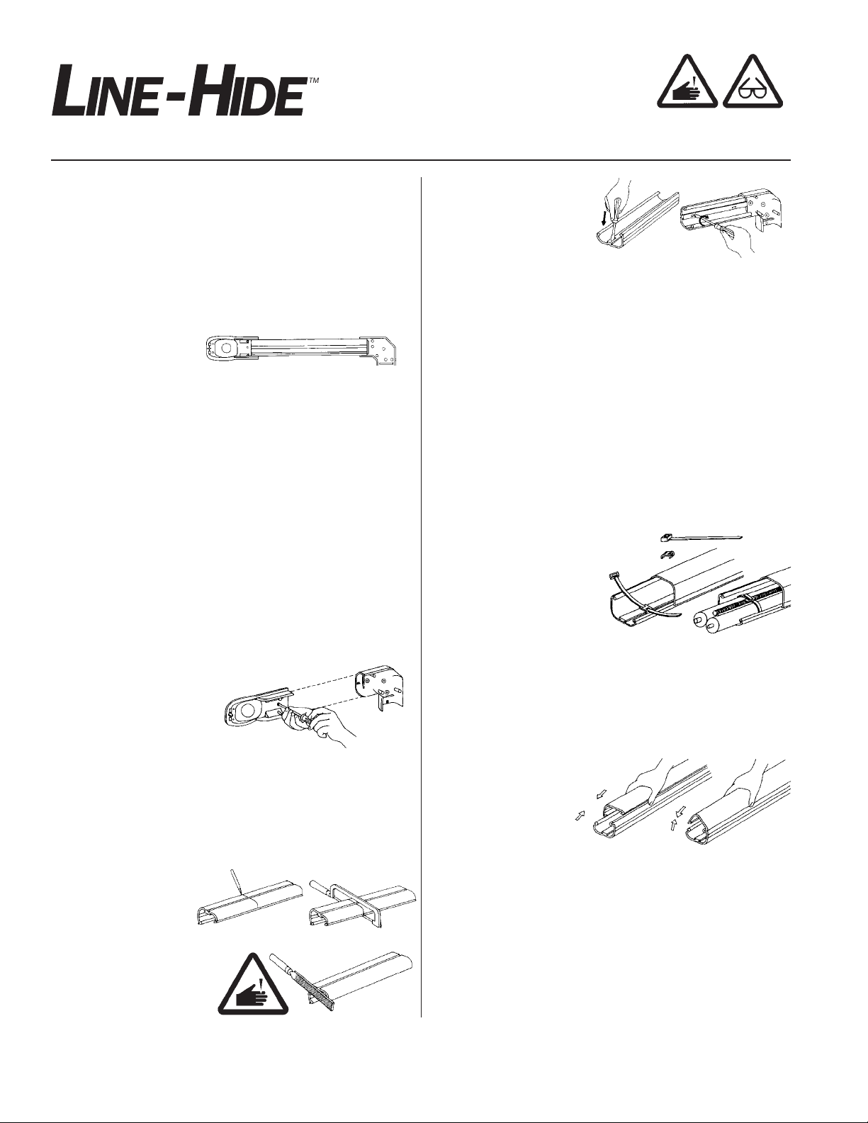
Step 2: Install Entry Fittings and Joint Bases
Most Line-Hide entry fittings and joints (including elbows)
include a base and a cover. Once you’ve determined where
your joints will be, install the bases. If you’re installing on wood,
simply position the base, and fasten it to the wall, using wood
screws. Don’t overtighten, or you’ll risk cracking the plastic.
For installations on a brick wall, mark the location for
each screw, and drill an anchor hole
using a masonry bit; then use
appropriate anchors and
screws.
Tube base;
To attach the Line Tube
base to the wall, first use
the tip of a screwdriver to
make a hole in the central
rib of the base (thin spots
are moulded in to accommodate installation). Then put a screw
through the hole in the tube, and tighten it to the wall. Be careful not to overtighten, for you may distort the tube. For the
smaller sizes (the 60 and 75 series), place screws approximately every twelve inches. For the larger sizes (the 100 and 140
series), use screws approximately every six inches.
Step 4: Install the Lineset
Unwind insulated refrigerant lines, and place into straight portion
of the tube. When installing insulated refrigerant pipe into a corner, adjust the pipe to the shape of the joint, and gently bend the
insulated refrigerant pipe without forcing it. Bending too quickly
can cause kinks in insulated refrigerant pipe and can pinch drain
pipe. Also try to avoid compressing the pipe insulation.
A Saddle Band (NV-S short or
NV-L long) can be used to fasten the insulated refrigerant
pipe, drain pipe, and electric
cable together in the Line
Tube. The saddle snaps to the
central rib of the tube base.
Thread the band through the
saddle and around the piping and cable, and pull it tight. This procedure will help to keep the pipes and wiring in place.
As a general rule, use one saddle band for every three feet (one
meter) of tube.
Step 3:
Measure the distance between the molded stops of each joint
base, and determine the length of tube needed. Line-Hide Line
ube is manufactured in six-and-one-half-foot (two-meter)
T
lengths so some straight runs are fabricated using two or more
lengths of tube and a socket/coupling.
o
T
the appropriate length;
then draw a perpendicu
lar guideline across the
tube. Use a hacksaw to cut
the tube along the line, and
then use a file to smooth the
cut edge.
LIOCA 10/07 10M ©2007 Mitsubishi Electric and Electronics USA, Inc., HVAC
Install Line
cut tube, measure and mark
Tube Base
-
Step 5: Assemble
the Line
When the Lineset is in
position, attach the tube
cover to the base. Slip
the lip on the short
edge of the cover into the trough on the high edge of the base.
Then squeeze the short end of the base while pushing the long
edge of the cover inward so that the lip and the trough engage.
Step 6: Assemble the Joints
With the Line Tube completely assembled, return to each joint,
and complete assembly
base; line up the holes; then secure cover to bases with the
stainless steel screws provided.
T
ube
. Position the cover of each joint over its
Page 3

Installation Instructions for
Specific Items
Wall Cover Inlet (NW):
Use where piping penetrates the wall.
Align wall cover base with hole in the
wall, and fasten to wall with appropriate screws. After completing tube
assembly, push the
tube downward (in
the direction of the
arrows) after aligning
the base with the
stopper built-in to the
top portion of wall
cover. This process will temporarily fasten wall cover.
Simple Wall Cover (NY):
One-piece inlet is used where refrigerant piping penetrates the
building wall.
Locate cover over Lineset, and mark mounting holes. Mount
and secure Line Tube to wall. Carefully bend refrigerant tubing,
drain and/or wiring into Line Tube. Place a bead of caulk on the
wall cover flange. Place Simple Wall Cover over wall opening,
and secure with appropriate screws and anchors.
Elbows – 90 degree horizontal (NE) and vertica l
(NC), 45 degree horizontal (NM) and vertical (NU),
and univeral horizonal (NX) and vertical (NZ):
Use where piping from the outdoor unit rises vertically or turns
horizontally along the wall.
Position the elbow base on the
wall where it will be fastened, and
attach to the wall with appropriate
screws. After installing tube, align
the elbow cover to the elbow
base, and attach with the stainless
steel screws provided.
All vertical elbows — NC, NU, NZ
— are reversible for use in both
inside and outside corner applica
tions. Cover screws can be inserted in either direction required.
-Joint (NT):
T
Use where piping branches off.
To change tube size, use the appropriate adapter set.
Contents of Accessory Adapter Sets
NT-75 75mm-60mm adapter 2 sets
NT-100 100mm-60mm adapter 2 sets
100mm-75mm adapter 2 sets
NT-140 140mm-100mm adapter 2 sets
-
Fit the accessory adapter base
appropriate for the proper size tube
into the
T-Joint to wall with the appropriate
screws. After tube base is
installed and the lineset
positioned, and the tube
cover snapped on, attach
theT-Joint cover to the
T-Joint base with the stainless steel screws provided.
T-Joint base. Fasten base of
Socket/Coupling (NS):
Use to lengthen and extend
tubes and to prevent tube
cover from sliding.
Mark the length of the tube;
then position the socket base
so that the tube will abut the
molded plastic stop of the
socket; then attach the socket
to the wall with appropriate screws. After installing tube, align
cover with holes in socket base, and fasten with the stainless
steel screws provided.
Variant Socket/Reducer (NJ):
Use to connect Line Tubes of different sizes.
Before attaching base to wall, determine that the converter corresponds to the varying tube sizes you’ll be joining and that it is
oriented properly on the wall. Then attach with the appropriate
screws. Locate Line Tubes, and install covers. Place socket
covers over base; align holes, and fasten with stainless steel
screws provided.
Flexible Joint (NF):
Use where piping bends over protrusion (such
as side molding) on wall.
If your installation requires the use of flexible
joint,
not split.
piping, and secure it in place.
o connect flexible joint to Line
T
joint into the end of tube base, and fasten it with appropriate
screws.
flexible joint.
against the tube to make a tight, strong connection. When the
assembly is complete, snap the tube cover onto the tube base
so that the end of the flexible joint is concealed.
ALL IT FIRST
INST
Simply slide the flexible joint over the
o help ensure a tight fit, compress the bellows of the
T
After the flexible joint is released, it will expand
. Fle
le joints are
xib
ube, slide end of the flexible
T
©2007 Mitsubishi Electric and Electronics USA, Inc., HVAC LIOCA 10/07 10M
Page 4

End Socket (NR):
Use to accommodate
arious lineset combi-
v
nations.
Before attaching the
end socket, determine
which of the various
openings will best accommodate your
Then remove the extra levels of plastic
lineset.
on the end socket. To do this procedure, score
the plastic with a utility knife (make sure you’re
wearing gloves) where you want to break it.
end socket in one hand, use pliers to grip the excess plastic,
and snap it off (make sure you’re wearing safety goggles, as
the plastic can break in unexpected ways). Use a file to smooth
any rough edges.
Attempting to snap the plastic without scoring it first will
NOTE:
likely crack the end socket.
With the excess plastic removed, attach the base with screws;
install the tube, and attach the cover. See the socket/coupling
instructions for more details.
Then, holding the
Universal Elbow, Horizontal (NX) and Vertical (NZ):
Use to change duct direction at an angle beween 45 and 90
degrees.
When elbow is angled at 0 to
15 degrees, break off the
protrusion inside the universal
elbow using pliers (as shown
at right) in the direction of the arrow.
For turns less than
15 degrees, remove
this plastic protrusion
Corner Cap/Soffit Entry Fitting (NA):
Use where piping
comes through ceiling,
wall, etc.
With Line Tube in
place, locate the bot
tom of the corner cap
against the wall, and
attach with appropri
ate screws. Then snap the top portion to the bottom portion and
attach it to the base with the stainless steel screws provided.
-
Lineset
-
exterior
wall
Wall Entry Fitting (NK):
Use to provide a good seal where
tube comes through wall.
Simply fit the bottom and top portions around the inlet hole in the
wall, and attach with appropriate
screws. Wall Entry Fitting may be
trimmed to fit by scoring the bottom portion, then snapping off
the excess plastic.
Caulking
To help ensure that the lineset remains free of corrosion and
mildew resulting from excess moisture, use caulking to seal
around the Line-Hide product where the lineset exits and enters
the wall.
WARNING: Flying fragments of plastic may pose
a hazard when breaking
off the protrusion inside
the universal elbow. Be
sure to wear safety glasses and gloves, and make sure that
others in the area are wearing appropriate safety gear as well.
LIOCA 10/07 10M ©2007 Mitsubishi Electric and Electronics USA, Inc., HVAC
3400 Lawrenceville-Suwanee Road
Suwanee, GA 30024
phone 678-376-2900
fax 678-376-3540
e-mail line-hide@hvac.mea.com
www.line-hide.com
 Loading...