

Page 1
Page 2

Contents
Safety precautions........................................................................3
1. Specifications ....................................................................... 4-8
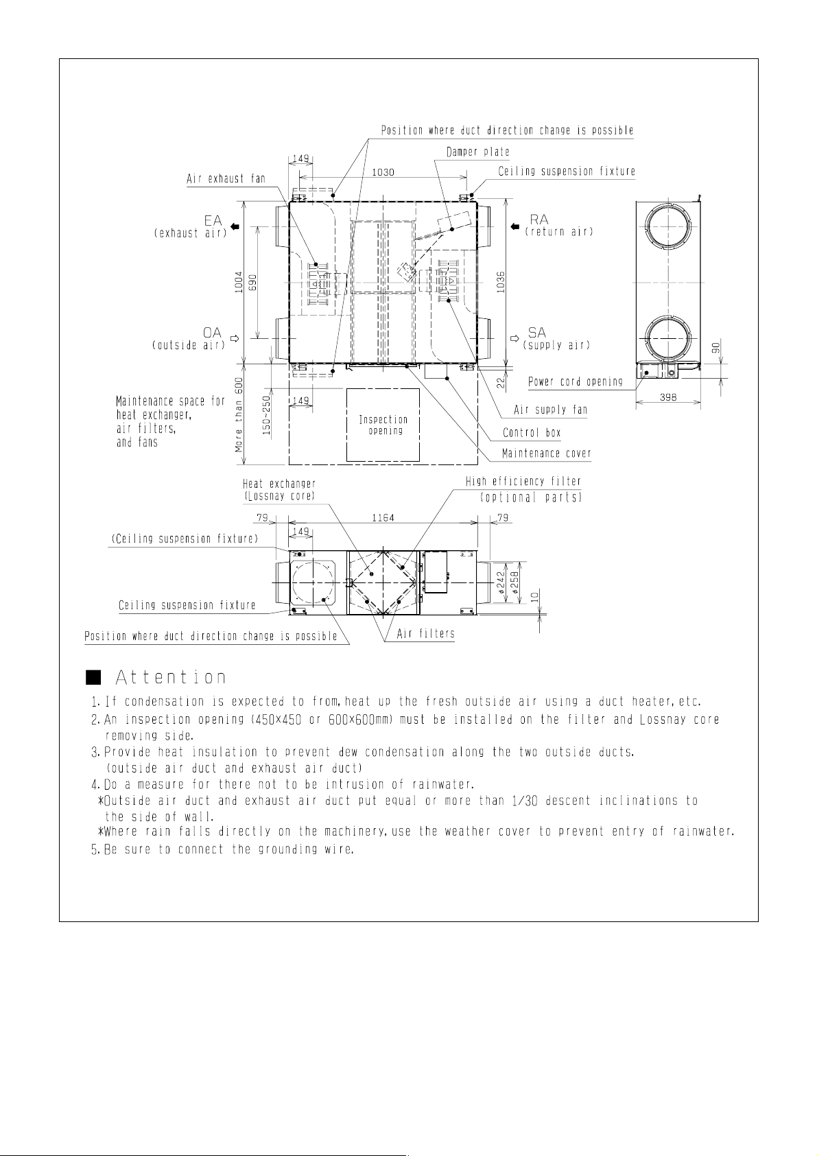
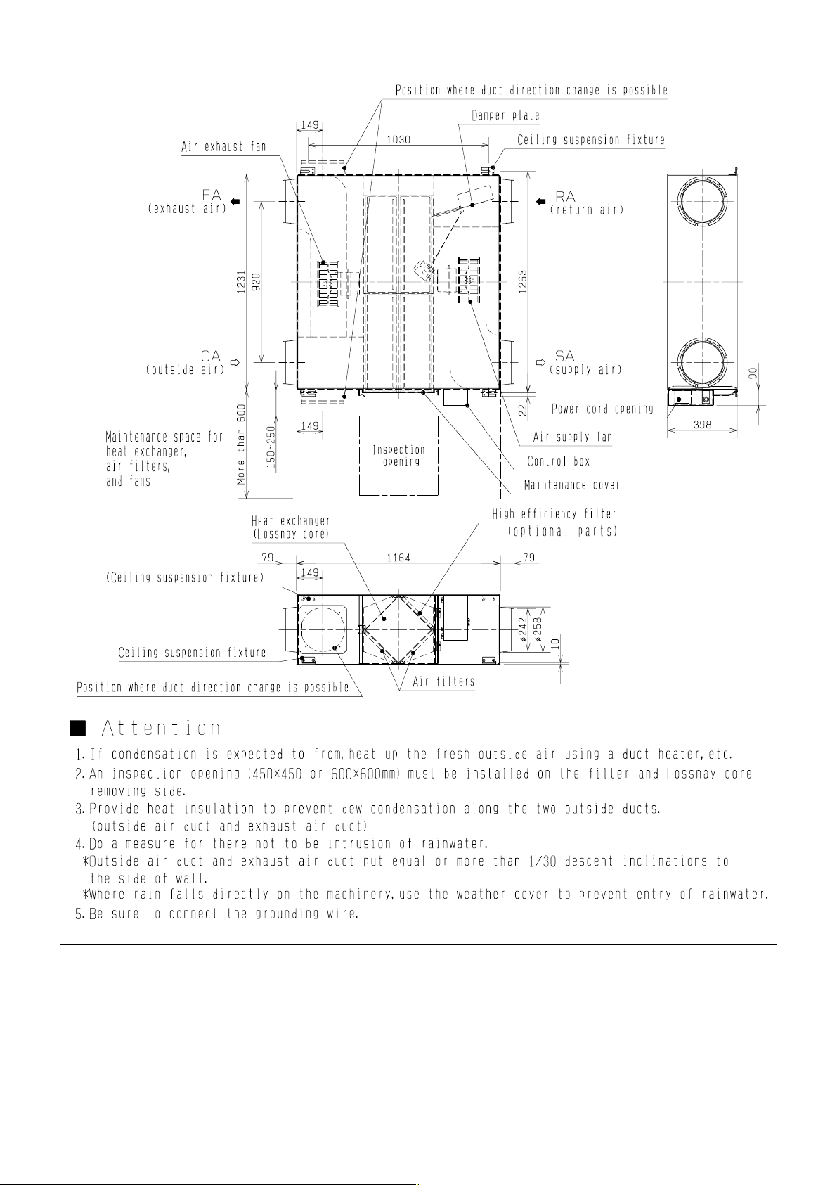
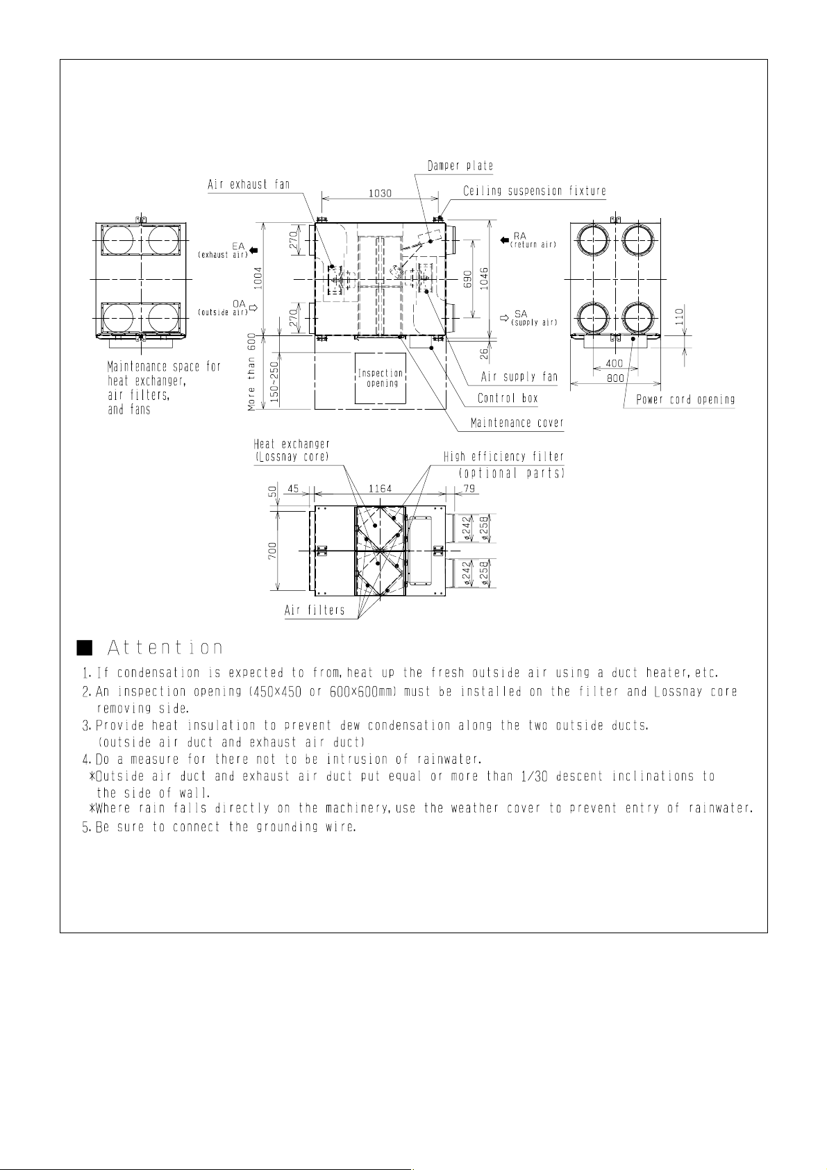
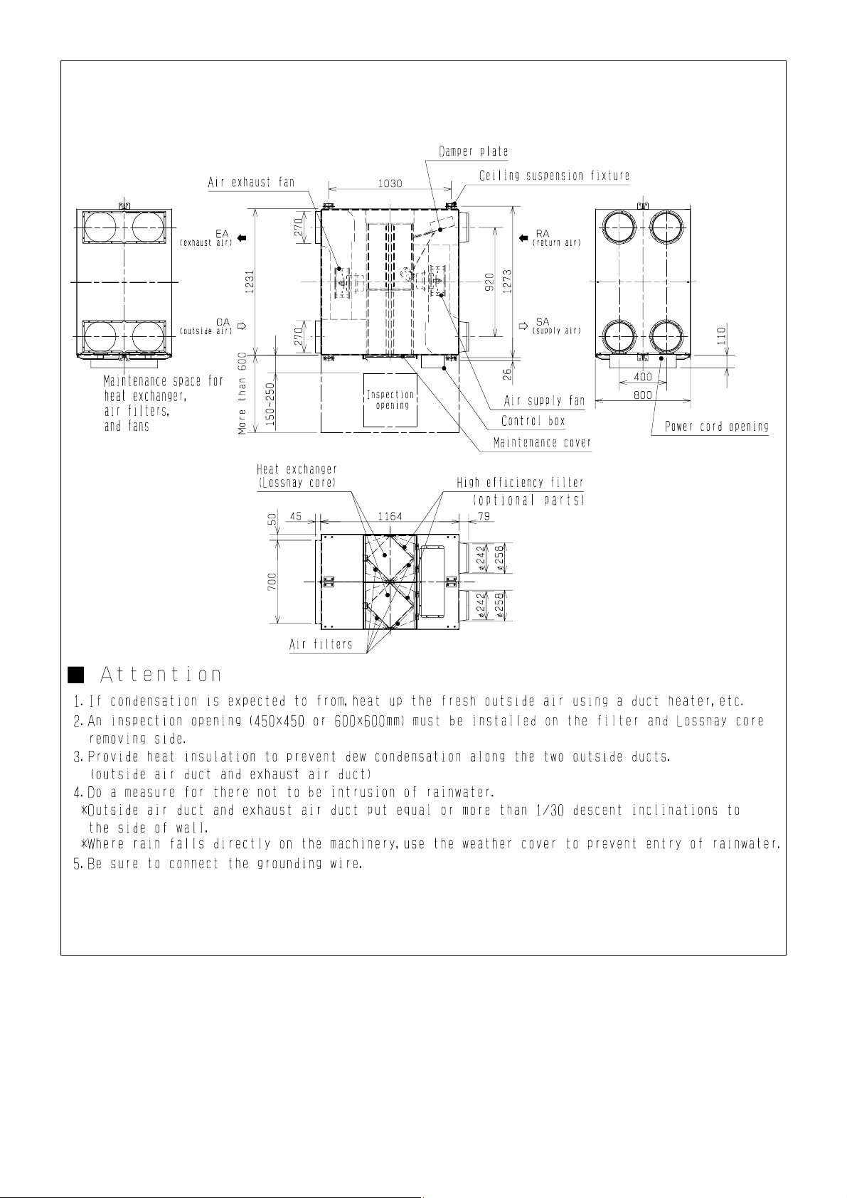
2. Dimensions ........................................................................ 9-17
3. Wiring diagrams ............................................................... 18-19
4. Troubleshooting ............................................................... 20-34
4-1 Service Flow.............................................................. 20-21
4-2 Items to Check .......................................................... 22-33
4-3 Circuit Test Point............................................................. 34
5. Overhaul procedures........................................................ 35-39
5-1 Blower Parts.............................................................. 35-36
5-2 Damper Movement Motor Part (All units available)........ 37
5-3 Circuit Board Part...................................................... 37-39
6. Parts list ........................................................................... 40-76
LGH-15RX4-E ............................................................... 41-44
LGH-25RX
4-E ............................................................... 45-48
LGH-35RX
4-E ............................................................... 49-52
LGH-50RX
4-E ............................................................... 53-56
LGH-65RX
4-E ............................................................... 57-60
LGH-80RX
4-E ............................................................... 61-64
LGH-100RX
4-E ............................................................. 65-68
LGH-150RX
4-E ............................................................. 69-72
LGH-200RX
4-E ............................................................. 73-76
Page 3
♦♦
Turn off the power supply
Be sure to shut off the breaker before disassembling the unit for repair.
(Failure to heed this warning may result in elec-
tric shock.)
♦♦
Use proper parts and tools
For repair, be sure to use the parts listed in the service
parts list of the applicable unit model and
use the proper tools.
(Failure to heed this warning may result in elec-
tric shock, fire and/or bodily injury.)
♦♦
Proper electric work
Use the electric wires designated for electric work, and
conduct electric work in accordance with the "Electric
Installation Engineering Standard," the "Indoor Wiring
Regulations," and the Installation Work
Guide.
(Incomplete connection or wiring installation may
result in electric shock and/or fire.)
♦♦
Replace damaged and/or degraded parts
Be sure to replace the power-supply cord and lead wire
in the event that they are damaged and/or
degraded.
(Failure to heed this warning may result in elec-
tric shock and/or fire.)
♦♦
Check insulation
Be sure to measure the insulation resistance once the
repair work is complete, and turn on the power supply
after verifying that an insulation resistance
of at least 10MΩ is obtained.
(If an insulation problem exists, it may result in
electric shock.)
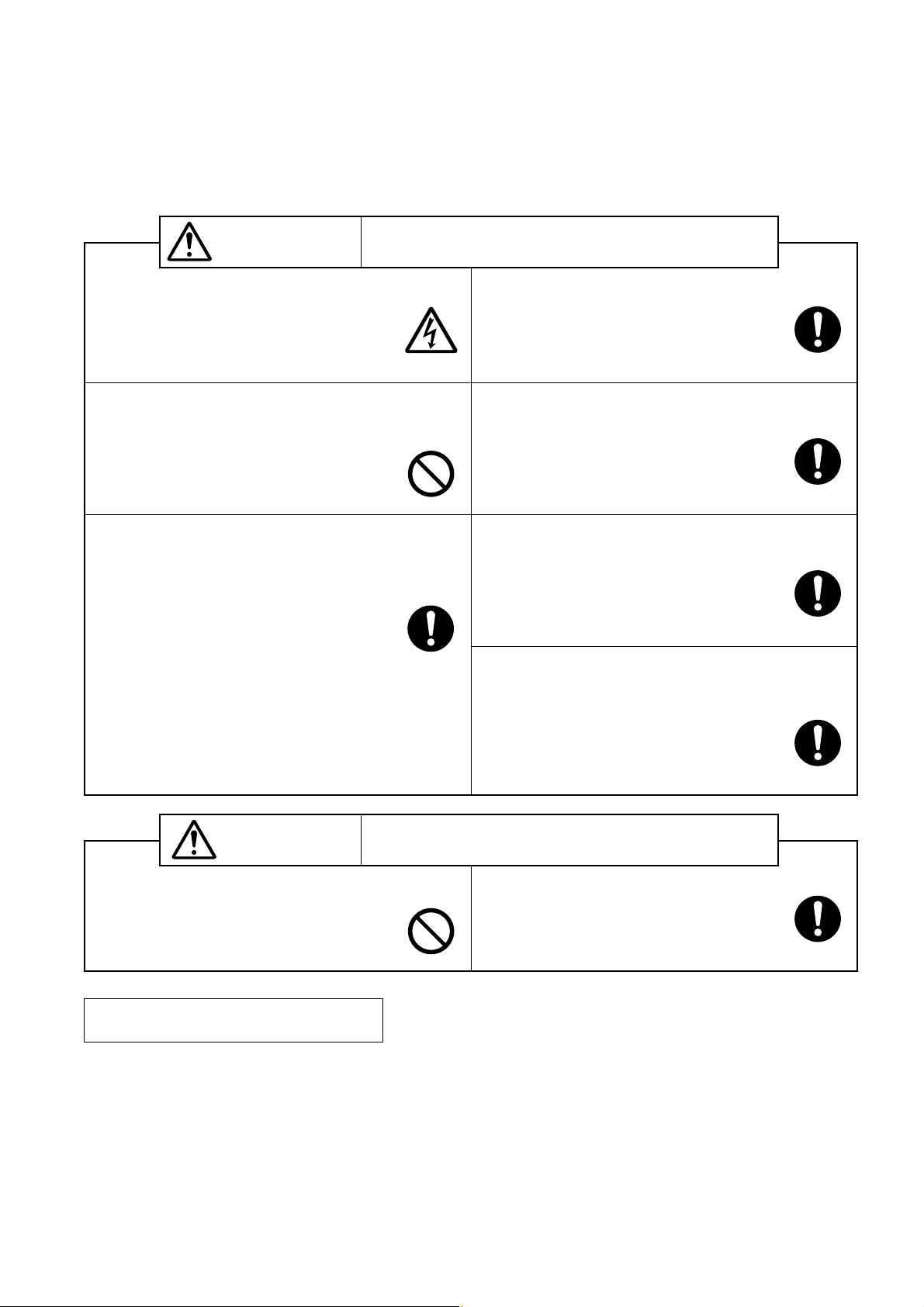
Safety precautions
●Please be sure to read the following safety precautions thoroughly before commencing with the maintenance
work, and conduct the inspection and repair of the product in a safe manner.
●The types and levels of danger that may arise if the product is handled incorrectly are described by using the
warning symbols shown below.
♦♦
Electric shock
If you must inspect the circuitry while the
power is on, do not touch the live parts.
(Failure to heed this warning may result in elec-
tric shock.)
♦♦
Modification is prohibited
Do not modify the unit.
(Failure to heed this warning may result in elec-
tric shock, fire and/or bodily injury.)
Incorrect handling of the product may result in serious injury
or death.
♦♦
Caution for bodily injury
Do not conduct any work at a location
where you do not have a sure footing.
(Failure to heed this caution may result in a fall.)
♦♦
Wear gloves
Wear gloves when conducting work.
(Failure to heed this caution may result in injury
to your hands from sharp metal or other edges.)
•Inspect the grounding, and repair it if incomplete.
●Make sure that the product operates correctly upon completion of repair. Clean the product as well as the surrounding area, and then notify the customer of the completion of repair.
Incorrect handling of the product may result in serious injury
or damage to properties including buildings and equipment.
Request during repair
—3—
Warning
Caution for
electric shock
Prohibited
Be sure to follow
this instruction.
Be sure to follow
this instruction.
Be sure to follow
this instruction.
Be sure to follow
this instruction.
Be sure to follow
this instruction.
Caution
Prohibited
Be sure to follow
this instruction.
Page 4
—4—
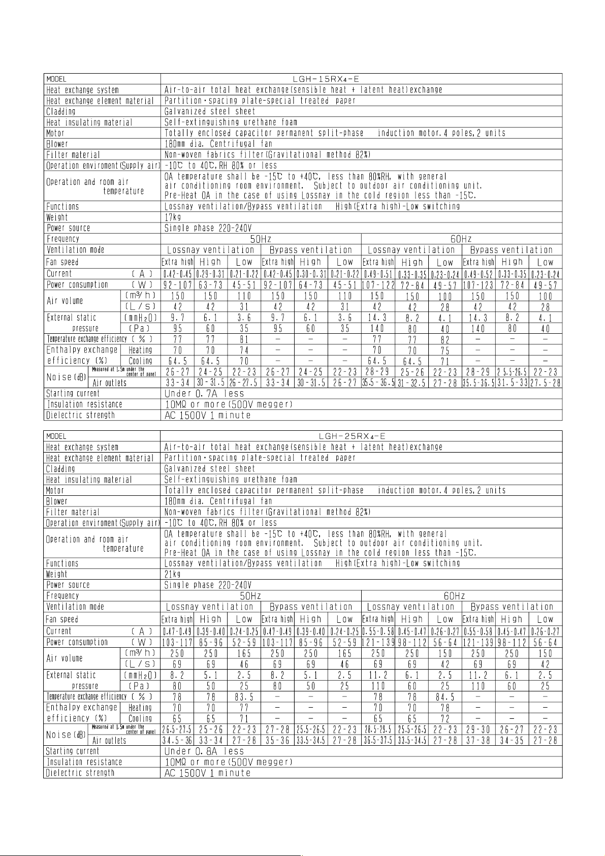
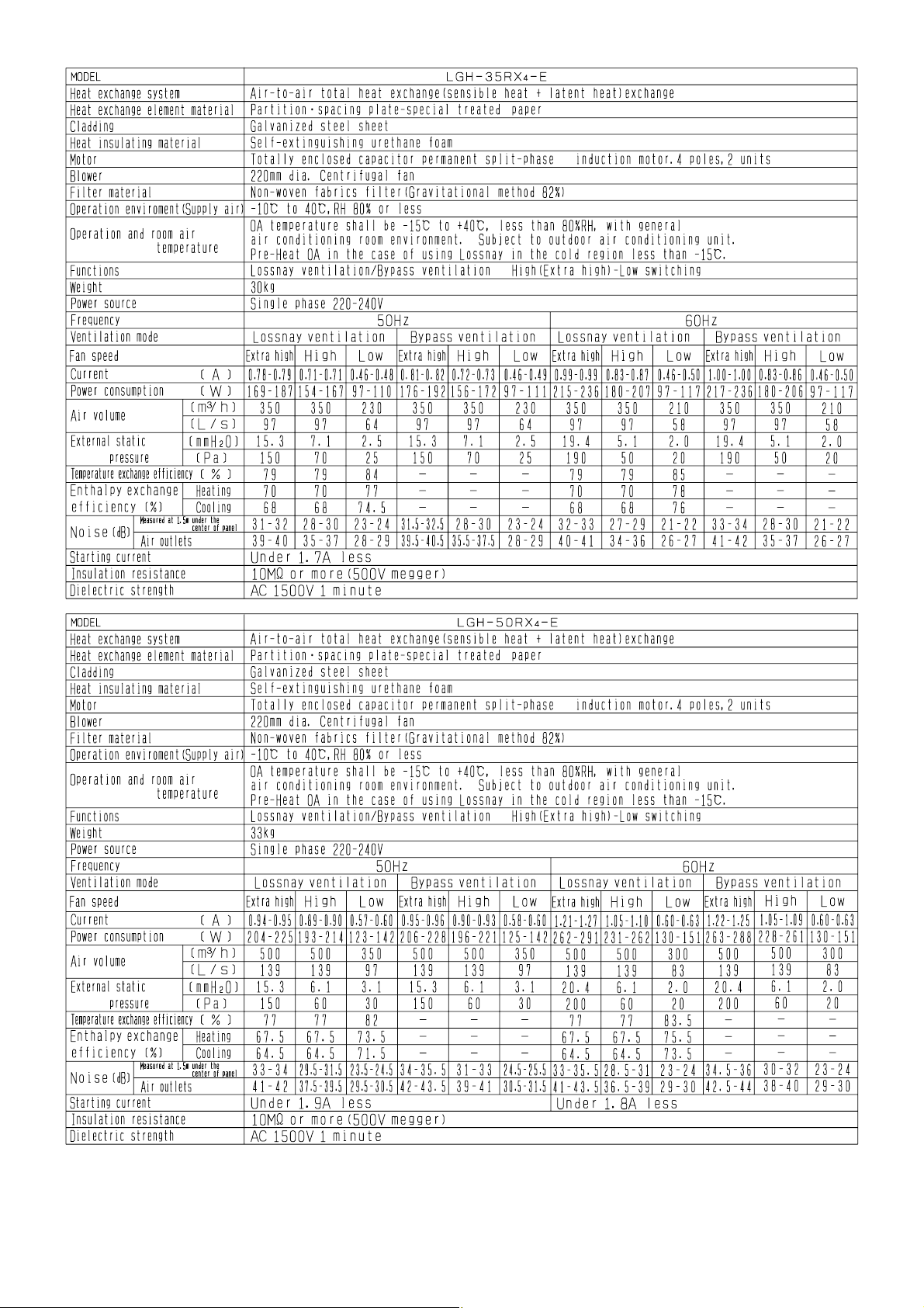
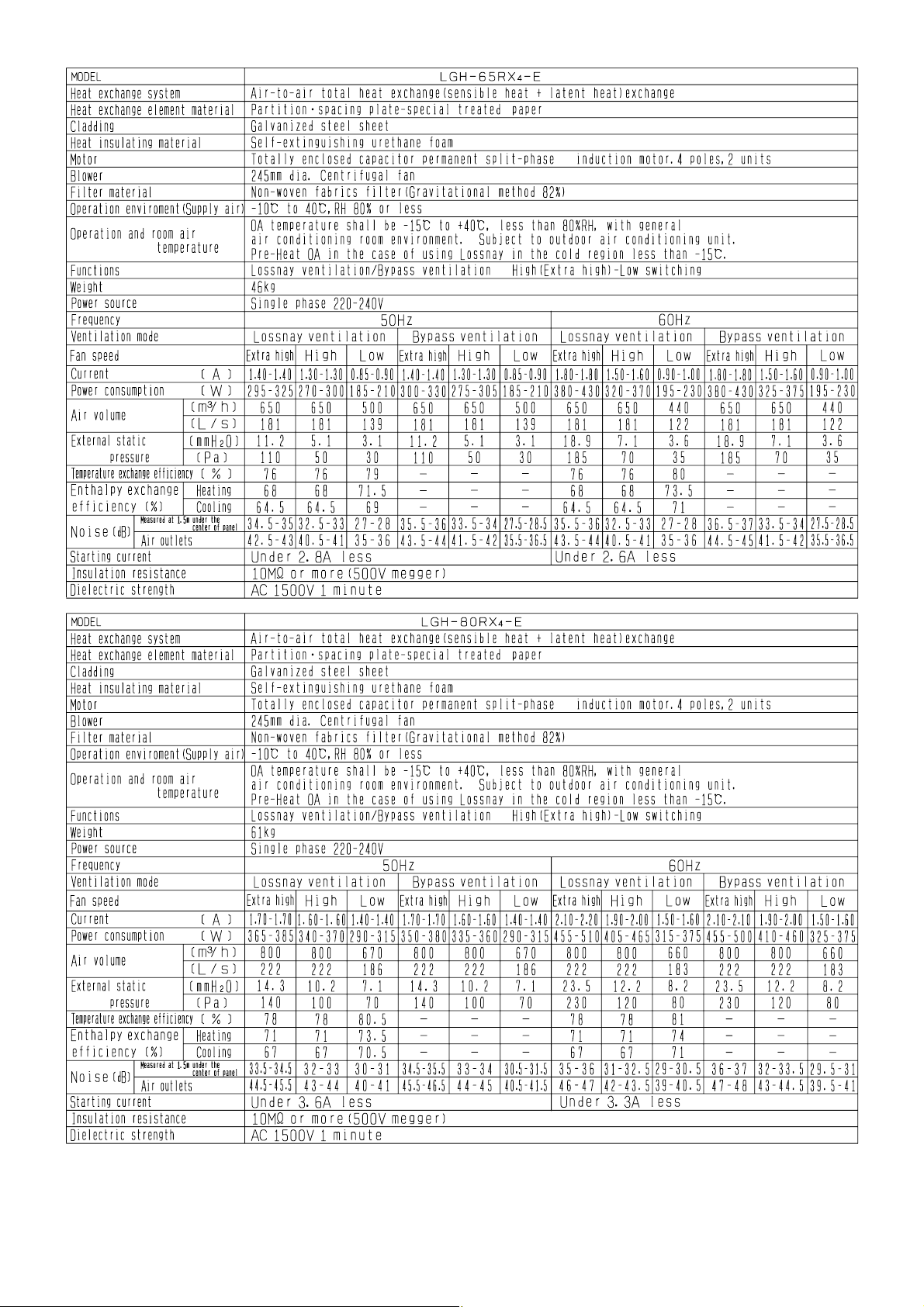
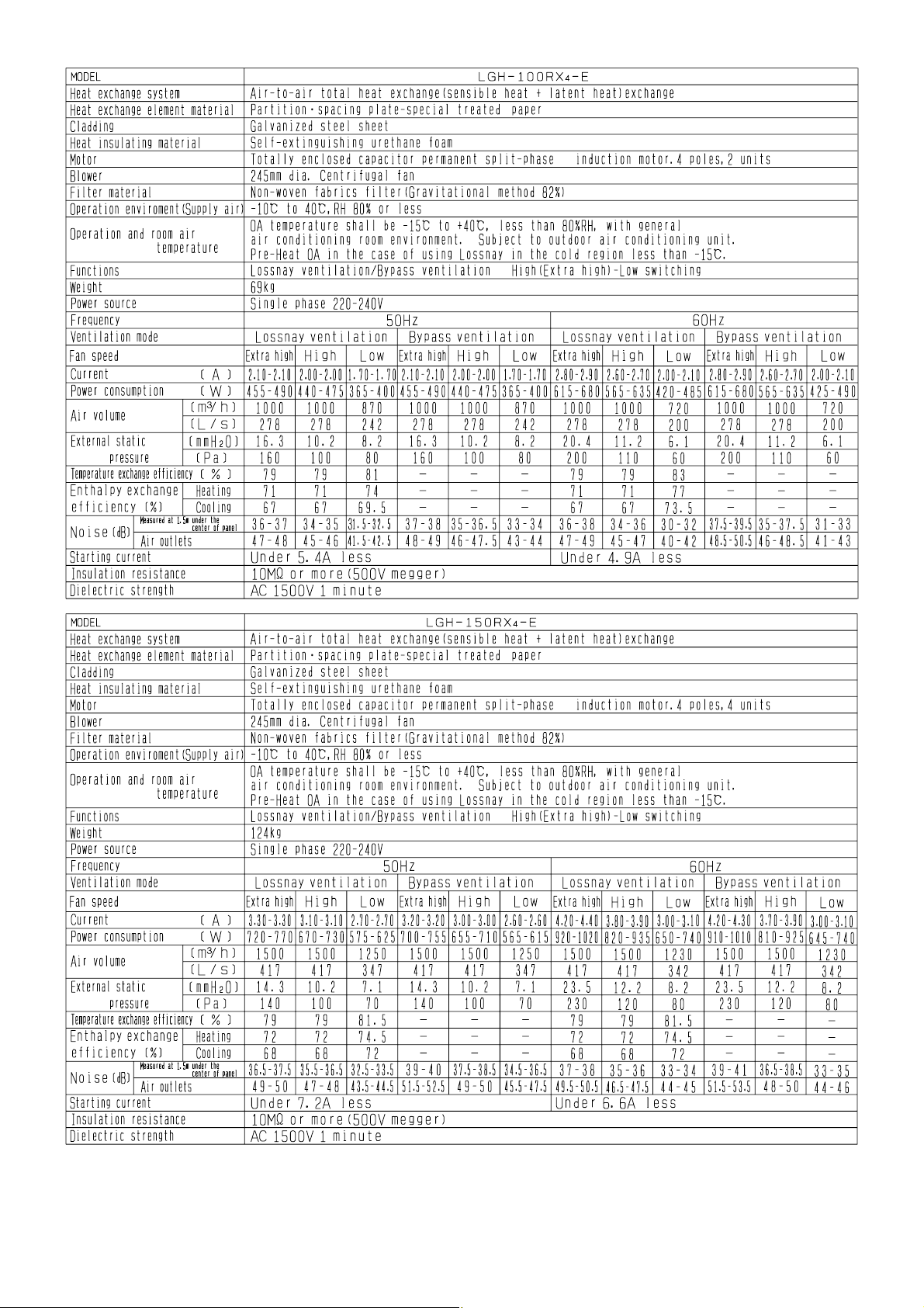
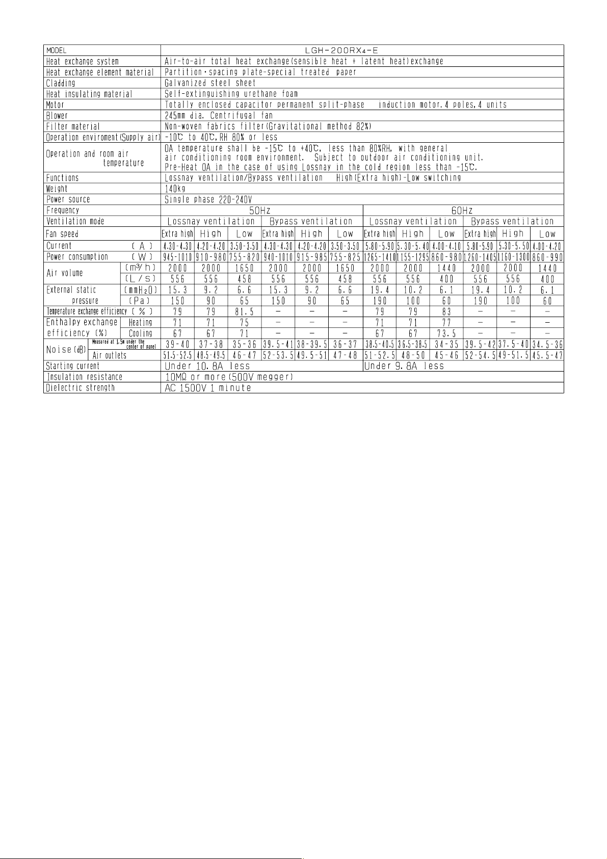
1. Specifications
Page 5
—5—
Page 6
—6—
Page 7
—7—
Page 8
—8—
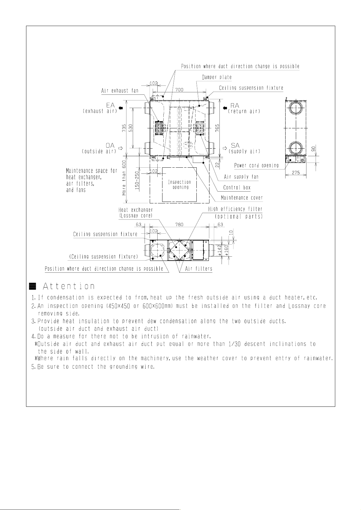
Page 9
Unit (mm)
LGH-15RX4-E
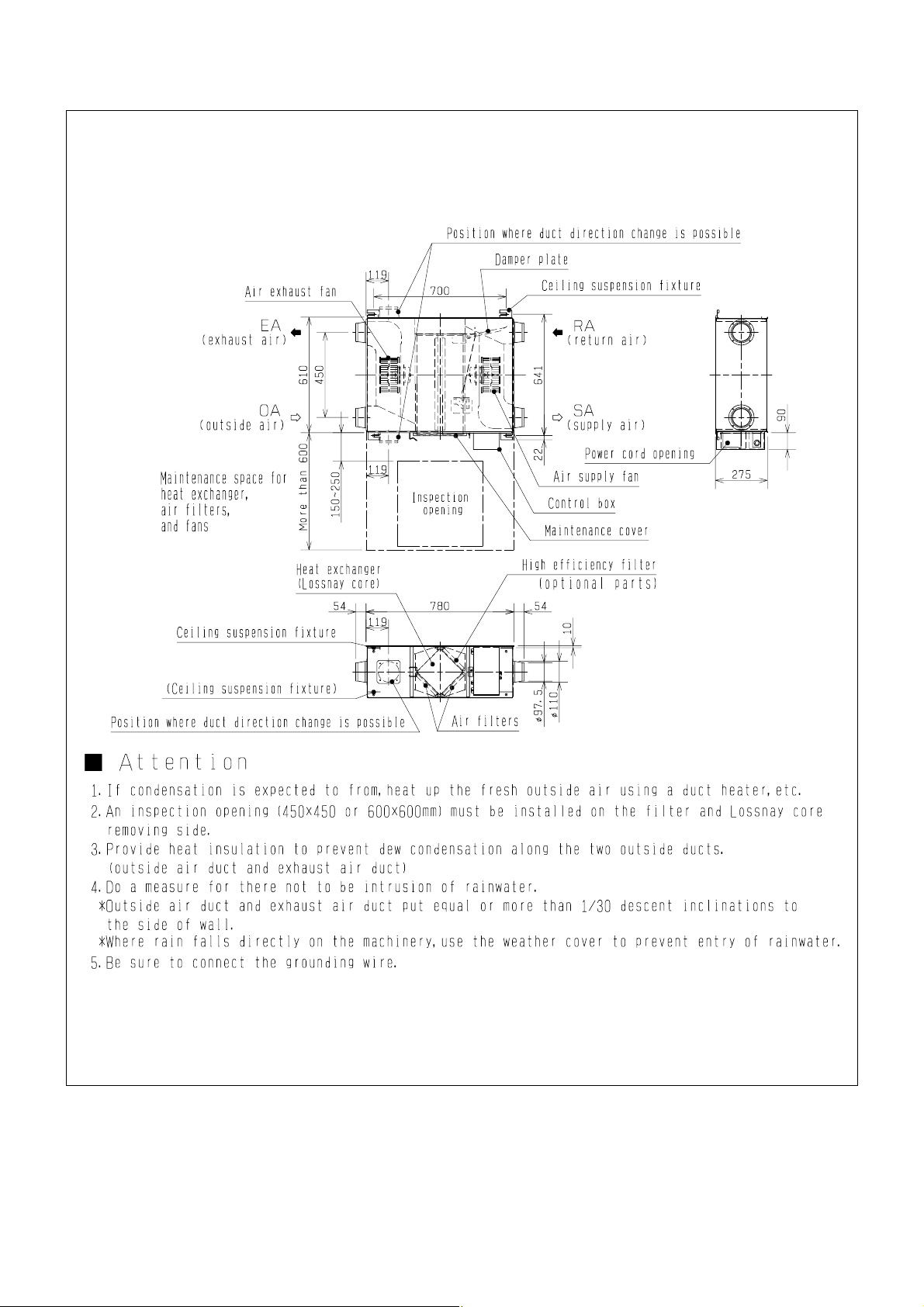
2. Dimensions
—9—
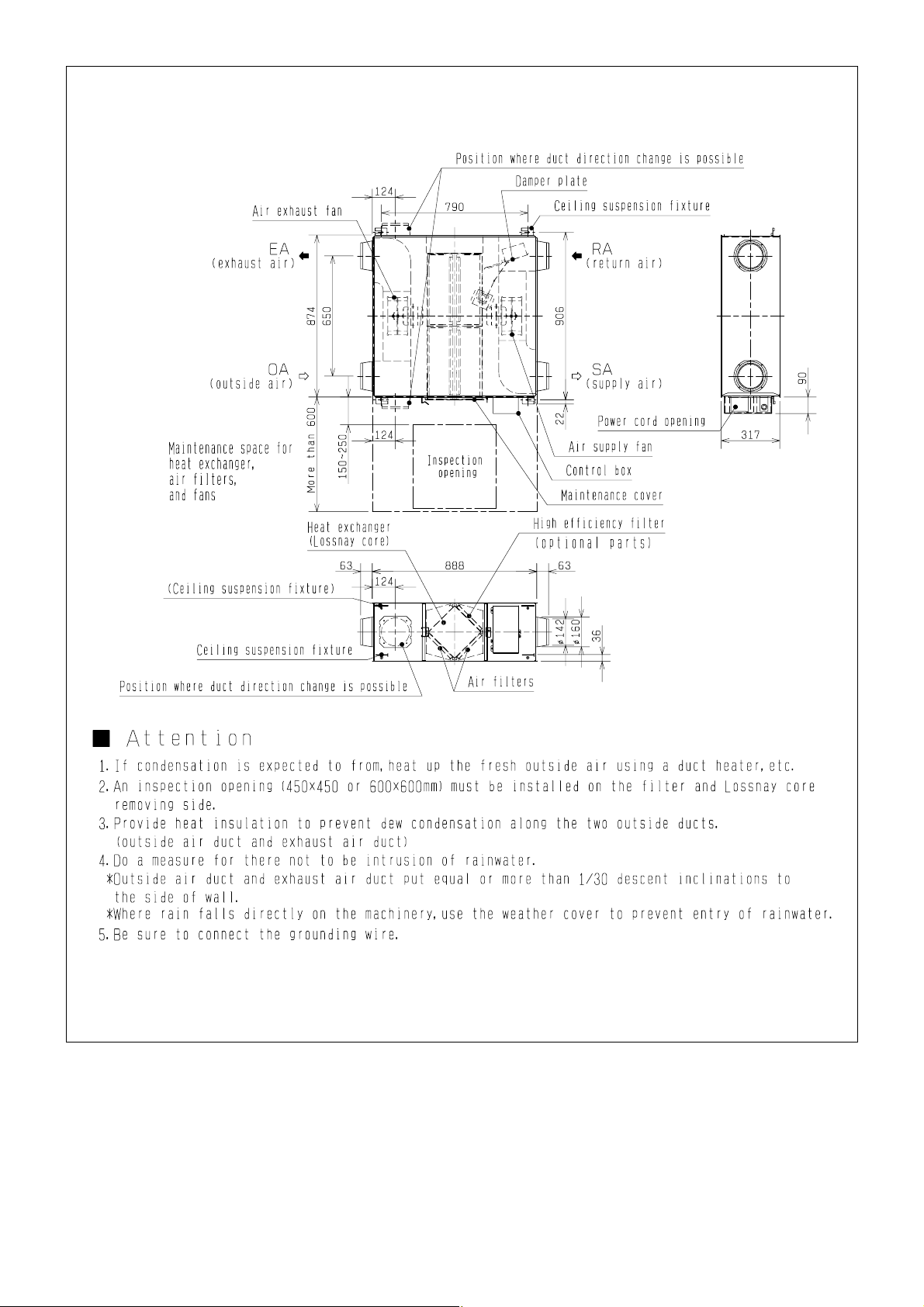
Page 10
Unit (mm)
LGH-25RX4-E
—10—
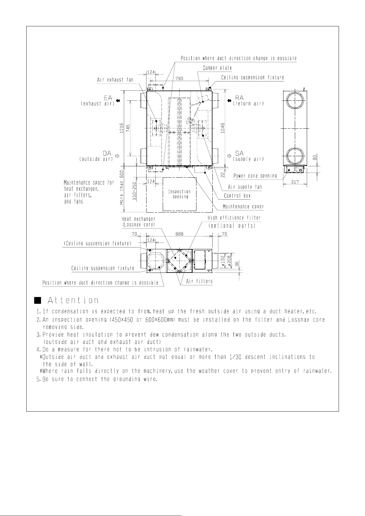
Page 11
Unit (mm)
LGH-35RX4-E
—11—
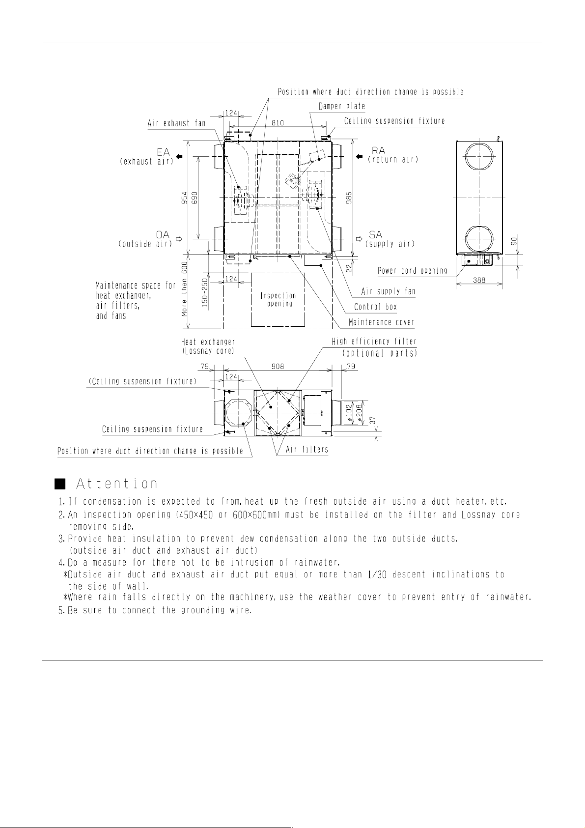
Page 12
—12—
Unit (mm)
LGH-50RX4-E
Page 13
Unit (mm)
LGH-65RX4-E
—13—
Page 14
—14—
Unit (mm)
LGH-80RX4-E
Page 15
Unit (mm)
LGH-100RX4-E
—15—
Page 16
—16—
Unit (mm)
LGH-150RX4-E
Page 17
Unit (mm)
LGH-200RX4-E
—17—
Page 18
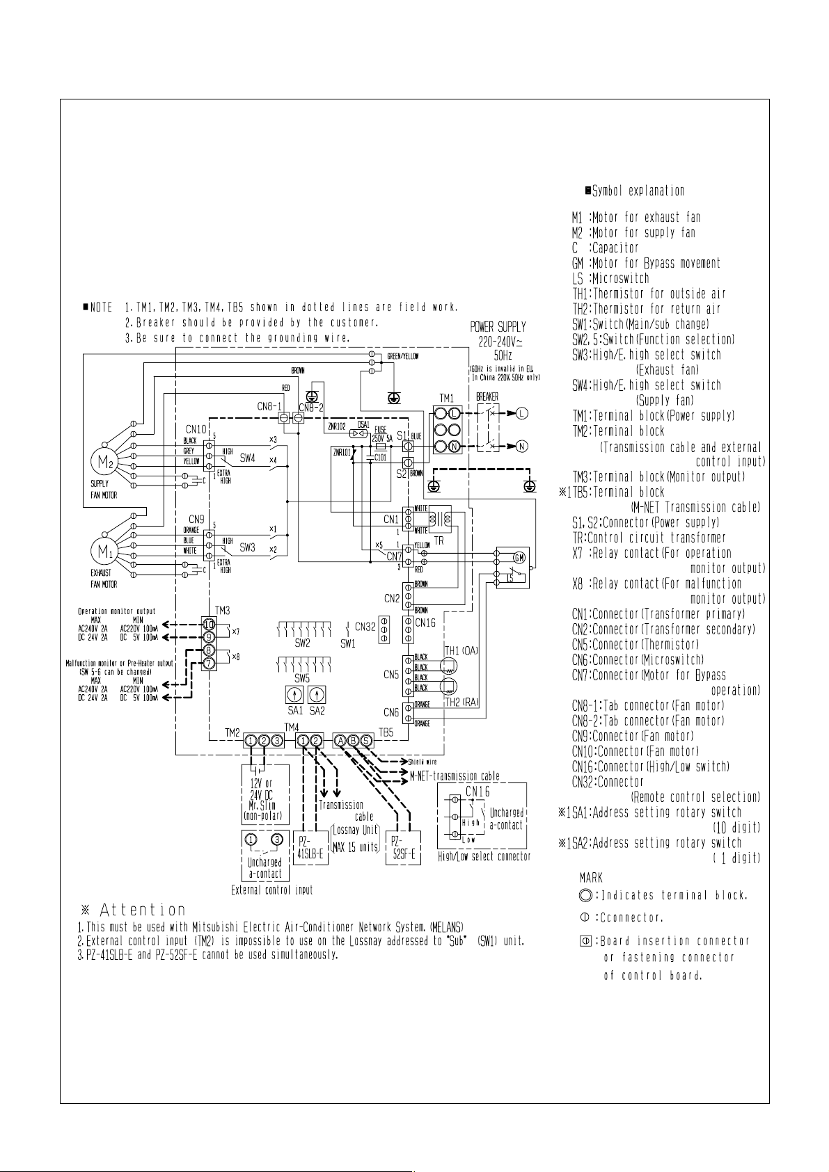
3. Wiring diagrams
LGH-15RX4-E,LGH-25RX4-E,LGH-35RX4-E,LGH-50RX4-E,LGH-65RX4-E,LGH-80RX4-E,LGH-100RX4-E
—18—
Page 19
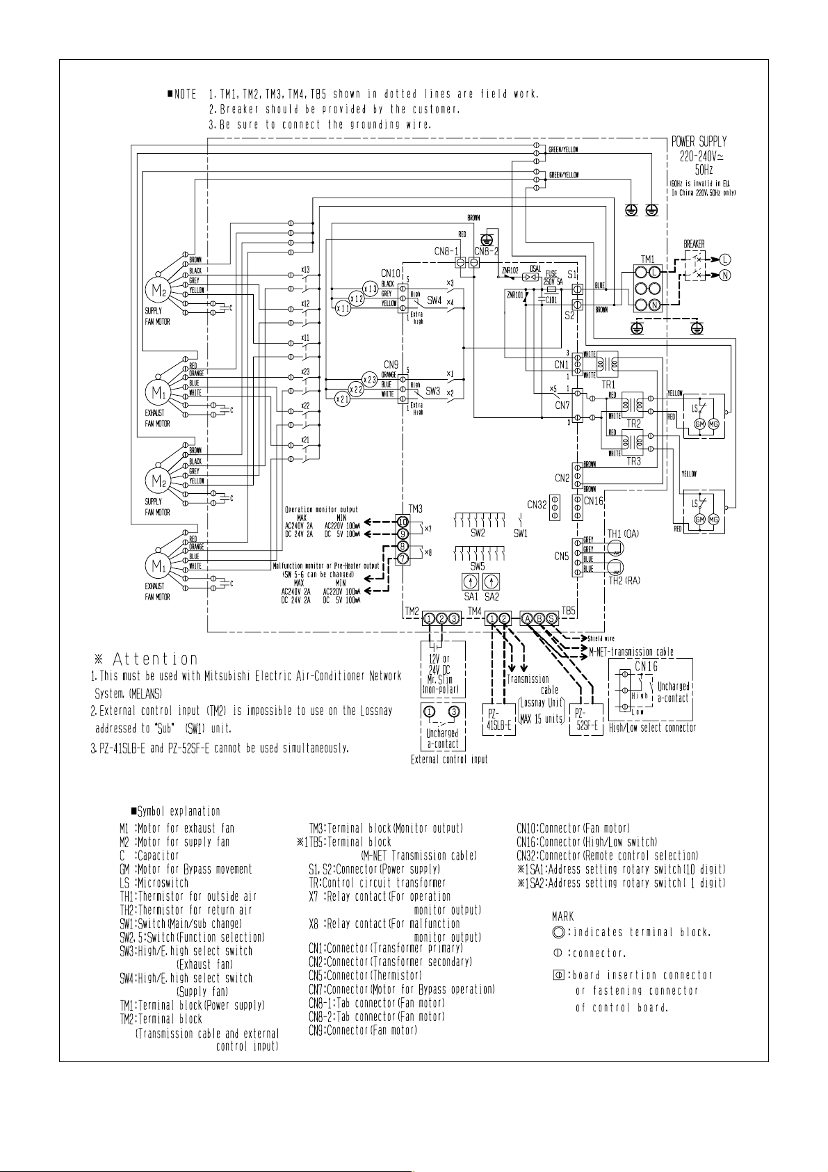
LGH-150RX4-E,LGH-200RX4-E
—19—
Page 20
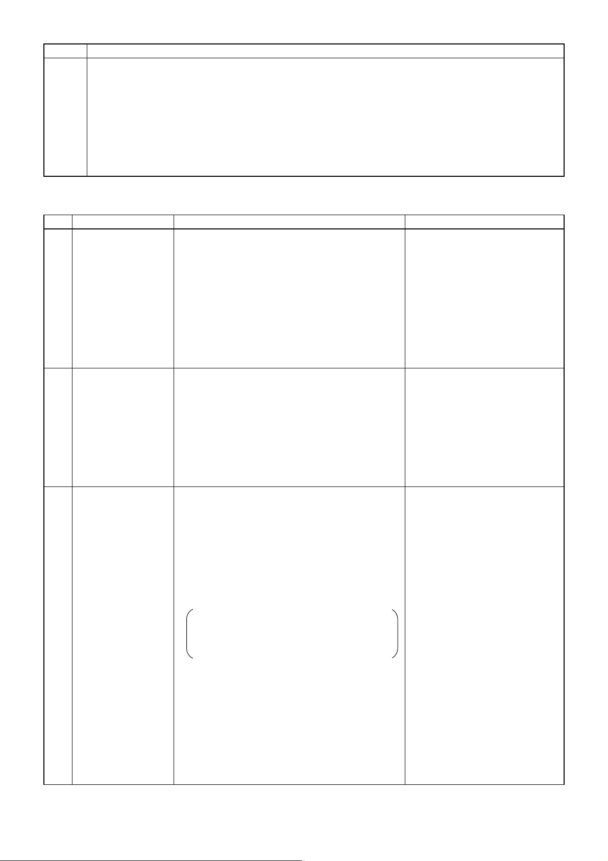
4. Troubleshooting
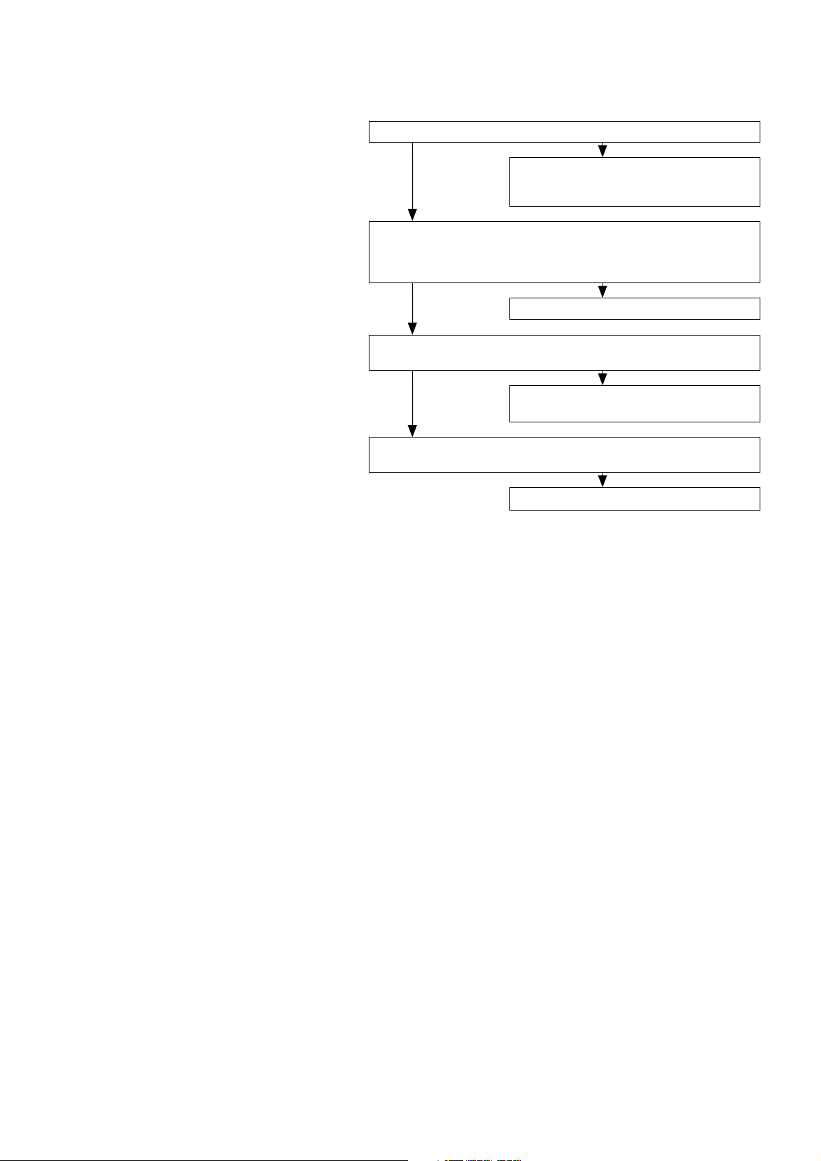
4-1 Service Flow
Confirmation items
1 Condition of trouble – remote controller dis-
play, etc.
2 Frequency of trouble – date of start of opera-
tion and occurrence
3 Occurrence timing
4 Existence of drawings, equipment (including
controllers and equipment sold separately),
cables, wiring, and settings.
Applicable models
Lossnay
LGH-15 to 200RX
4-E
Remote controller
PZ-41SLB-E
PZ-52SF-E
Trouble Mode 1 The system will not start properly.
• Check the initialization checklist from
installation to operation (table 1-1).
• Check the system checklist (table 1-2).
Trouble Mode 2
• The check code display appears on the
remote controller.
• The LED of the Lossnay circuit board is
blinking.
Check with the check code list (table 2).
Trouble Mode 3
The remote controller does not operate or
operates irregularly.
The Lossnay does not operate or operates
irregularly.
Trouble Mode 4
Check with the remote controller checklist
(table 3).
Check with the Lossnay checklist (table 4).
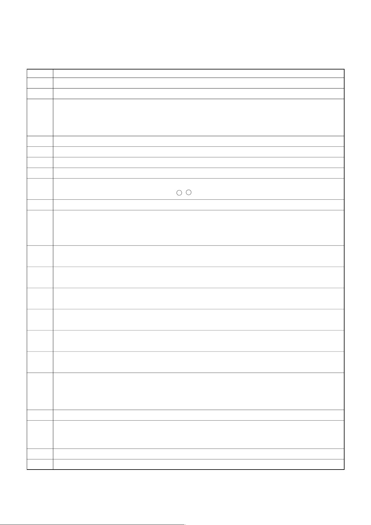
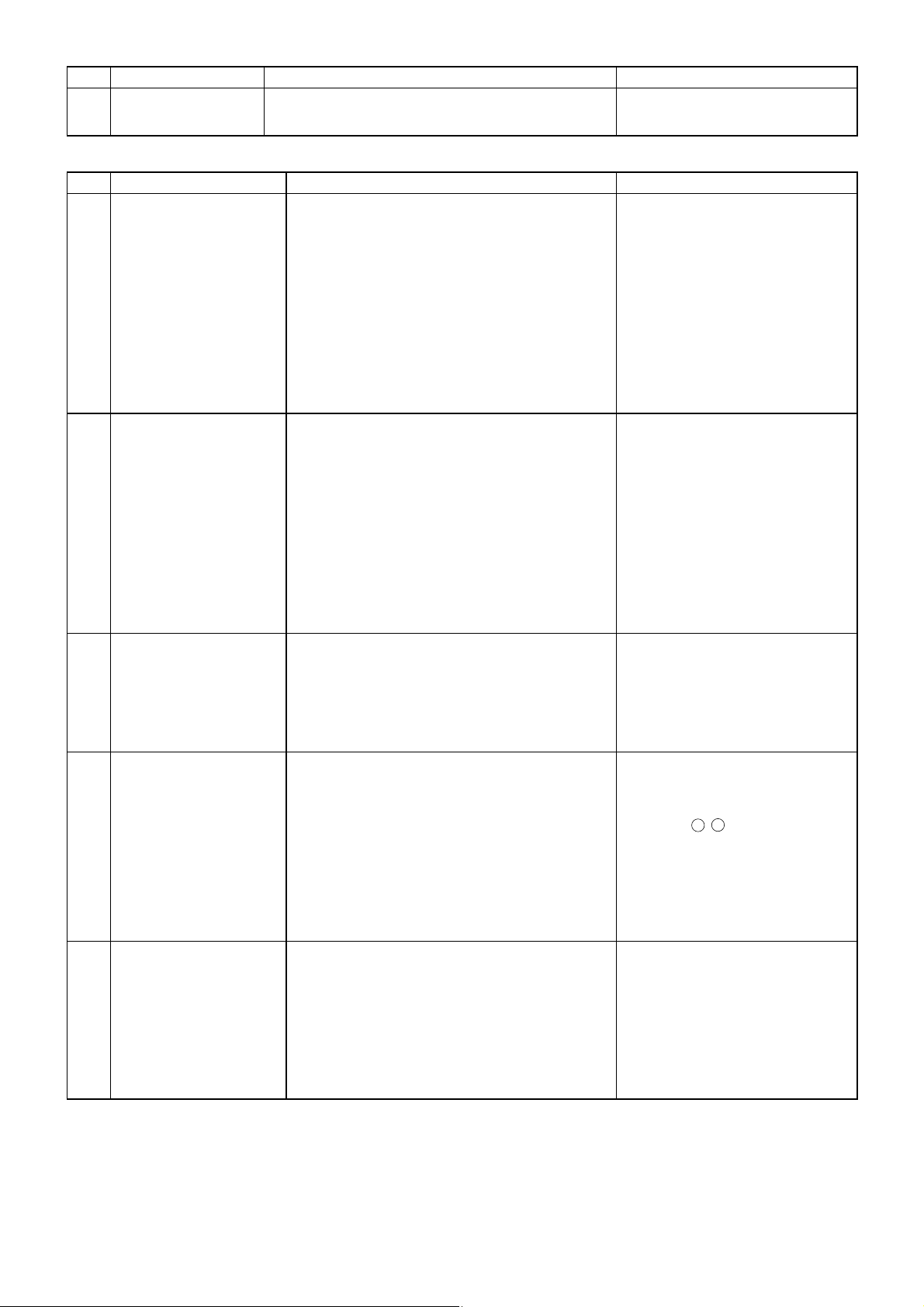
Precautions when diagnosing malfunctions
● When removing a transistor or printed circuit board, make sure the breaker is thrown.
● When removing the circuit board, always hold it at both ends and remove carefully so as not to apply force to the surface
mounted parts.
● When removing the circuit board, be careful of the metal edges on the board.
● When removing or inserting the connectors for the circuit board, hold the entire housing section. Never pull on the lead
wires.
● When servicing, be sure to recreate the malfunction 2 to 3 times before starting repairs.
● If a malfunction of the printed circuit board is suspected, check for disconnected wires in the print pattern, burnt parts or dis-
coloration.
● If the printed circuit board is replaced, make sure that the switch settings on the new board are the same as the old board.
—20—
Page 21

Error List
Unit error
——
Error item
—
«
«««
««
«
«««
«
«
—
—
«
—
«««
————
—
—
—
—
« «««
—
—
«« «
«« «
—
«« ««
—
«« «
—
«« «
«
—
«« «
2 times
3 times
4 times
8 times
—
—
—
—
—
—
—
9 times
—
—
—
—
—
6 times
—
—
8 times
1 - 5
times
LED 6
turn off
—
4000/4116
*1)
3602
*2)
5101
3126
0900
6600
6607
6608
6607/6608
6602/6603/
6604
—
6608
• Cancellation
• Cancel damper operation
• Other controls as normal
•
Lossnay ventilation
fixed (for “Auto” modes)
•
Other controls as normal
•
The Pre-heat output
(X8) turns OFF
• Fan: High speed
• Lossnay ventilation fixed
—
—
—
• Cancellation
—
—
• Cancellation
Fan motor
operation
device error
Damper motor
error
OA
temperature
sensor error
Pre-heat error
«««
—
«
5 times —5102
•
Lossnay ventilation
fixed (for “Auto” modes)
•
Other controls as normal
RA
temperature
sensor error
Test operation
Dual address
No ACK
No response
Controller
communication
error
Communication
circuit error
««« ««
9 times —
6801
*3)
• Restricted to ON/OFF
Local transmission cable communication
error
Polarity not set
PZ-41SLB-E
communication error
ClassificationCommunication error
Measures taken by
Lossnay
Remote
controller
display
error
code
LED 1
(green)
Display
(No. of
blinks)
LED 2
(red)
Display
(No. of
blinks)
Error
monitor
output
*4)
Reset
power
supply
Change
address
Stop
↓
Start
Error
delete
Cancellation measures
*1) “4000” is displayed on PZ-41SLB-E only.
*2) This error is not generated in the LGH-150RX
4, LGH-200RX4 model.
*3) “6801” is displayed on the M-NET controllers only.
*4) Since the error monitor output will turn into the preheat output if SW5-6 is turned ON, it becomes impossible to use it.
—21—
Page 22
Do the capacity of the main power supply on/off unit and wiring span meet specification?
Checkpoint
1
No.
2 Is the specified power supplied to the Lossnay power terminal (TM1)?
3 Is the wiring length of the transmission cable within specifications?
When using PZ-41SLB-E: Overall extension within 500 m
When using M-NET: Maximum power supply length within 200 m, maximum distance between ends
within 500 m
4 Does the transmission cable meet regulations? (Type, diameter)
5 Is the transmission cable wired at least 5 cm away from the power supply cable?
6 Are multiple transmission or signal cables wired to the same power cable duct?
7 Are multiple transmission cables wired with multi core cables?
8 Is the transmission cable connected to the terminal unit?
(PZ-41SLB-E to TM4 1, 2; M-NET to TB5
A , B )
9 Is the transmission cable securely connected to the Lossnay terminal unit?
10 When not using M-NET
If using 1 Lossnay unit, is the Main/Sub change switch (SW1) on the Lossnay circuit board set to “Main”?
If using 2 or more Lossnay units, is the Main/Sub switch set to “Main” on only one unit, and the other units are set
to “Sub”?
11 When using M-NET
Is the address switch on the Lossnay circuit board (SA1, SA2) set to the correct number?
12 When using external control input
Do the specifications of the external signal match specifications of signals that can be input to the Lossnay?
13 When the external input signal is a pulse signal
Is the pulse input switch (SW2-2) on the Lossnay circuit board set to ON?
14 When the external signal is 12V DC, 24V DC, or Mr. Slim (A-control or K-control) signal
Is it connected to 1, 2 on the Lossnay external control input terminal unit (TM2)?
15 When the external signal is an uncharged a-contact signal
Is it connected to 1, 3 on the Lossnay external control input terminal unit (TM2)?
16 When M-NET is not being used
Is the external input signal connected to the Lossnay set to “Main”?
17 Is the signal cable length within wiring specifications?
12V DC, 24V DC signal: Within limitation of the external device
Uncharged a-contact signal: Within 500 m
Mr. Slim (A-control or K-control) signal: Within 500 m
18 Is the signal cable wired at least 5 cm away from the power supply cable?
19 Is the output capacity of the Lossnay operation monitor/malfunction monitor (pre-heat output) within specifications?
Operation monitor output: Maximum 240V AC/24V DC 2A, minimum 220V AC/5V DC 100 mA
Maifunction monitor output/pre-heat output:Maximum 240V AC/24V DC 2A, minimum 220V AC/5V DC100 mA
20 Are the power supply cable, transmission cable, signal cable, etc., securely connected to the proper terminals?
21 Are the settings for the Mai/Sub switch, address switch, and function select switch correct?
4-2 Items to Check
(1)Trouble Mode 1: The system will not start properly.
Initialization checklist from installation to operation (Table 1-1)
After checking the system, check the points below up to operation.
—22—
Page 23
22 When pre-heat output output is used, turn the SW5-6 ON.
There is no method of turning ON the pre-heat output without changing OA temperature.
The first check of the installation
(1) Make the power supply of the heater turned off.
(2) Short-circuit the pre-heater output with a lead etc.
(3) Check weather the relay contact by the side of the heate rturns on.
The pre-heat output is never closed even if abnormalities, such as drawing out the OA/RA thermistor connector,
occur.
« Check the power supply to the
Lossnay.
« Set the Main/Sub (SW1) switch
to “Main.”
« Check the length of the trans-
mission cable wiring.
« Connect the transmission cable
to TM4 12.
« Change to the PZ-41SLB-E
remote controller.
1
No.
Remote controller
display does not
appear.
« Power is not supplied to the Lossnay, or power
outside specifications is connected.
« When using only 1 Lossnay, the Main/Sub switch
(SW1) on the Lossnay circuit board is set to “Sub.”
« The overall wiring length of the transmission cable
is longer than specifications (longer than 500 m).
« The remote controller is connected to TB5 (M-NET
transmission cable).
« PZ-52SF-E is connected to the Lossnay local
remote controller.
2 Remote controller
does not operate
(Communication error
display)
« When using multiple Lossnay units, the Main/Sub
switch (SW1) on the Lossnay circuit board of the
second or following unit is set to “Main.”
« The overall wiring length of the transmission cable
is longer than specifications (longer than 500 m).
« Multiple transmission cables are wired with multi
core cables.
«
Set the Main/Sub switch (SW1) of
the second and following Lossnay
units to “Sub.”
« Check the length of the trans-
mission cable wiring.
« For the applied transmission
cable, wire the transmission
cables away from the other
transmission cable.
3 Interlocked operation
with external device
does not occur.
« The type of external signal does not match the
connected terminal unit (charged, uncharged, Mr.
Slim signal).
« The type of external signal does not match the
pulse input switch (SW2-2) setting (level signal,
pulse signal).
« The external device signal is not being input.
« The external device and signal cable wiring is
longer than specifications
12V DC, 24V DC: Longer than limitations of
external device
Uncharged a-contact: Longer than 500 m
Mr. Slim signal: Longer than 500 m
« The Delayed Start mode is set at the remote con-
troller (PZ-41SLB-E).
« The ON Interlocked Operation mode or OFF
Interlocked Operation mode is set at the remote
controller (PZ-41SLB-E).
« When using multiple Lossnay units, the external
control input signal is connected to a unit with the
“Sub” setting made.
«
Check the connection to the external control input terminal (TM2) for
the type of external signal.
«
Check the type of external signal
and the setting of the pulse input
switch (SW2-2).
« Check the external device.
« Check the length of the signal
cable wiring.
« Check the Delayed Start mode
setting at the remote controller
(PZ-41SLB-E).
« Check the Interlocked Operation
mode setting at the remote controller (PZ-41SLB-E).
« Connect the external control
input signal to the Lossnay unit
set to “Main.”
Symptom Cause Corrective action
System checklist
1Use this checklist when using a PZ-41SLB-E or an external device (Table 1-2-1)
—23—
Checkpoint
No.
Page 24
« Turn the SW5-6 ON.
« Operate onry below -5˚C.
4
No.
Pre-heat control does
not work.
« SW5-6 is OFF.
« OA temprature is larger than -5˚C.
Symptom Cause Corrective action
2System checklist when using the M-NET (Table 1-2-2)
« Check the Lossnay address, and
set for an address corresponding to interlocked operation.
« Check the length of the trans-
mission cable wiring.
«
Change to the PZ-52SF-E remote
controller (PZ-41SLB-E can not
be used with the M-NET).
1
No.
Does not interlock with
City Multi. (The Lossnay
cannot be operated by
the ventilation switch on
the ME remote controller,
MA remote controller, or
MELANS.)
« The Lossnay is not set for interlocked opera-
tion, or is set for interlocked operation at the
wrong address.
« The length of the M-NET transmission cable
wiring from the outdoor unit or the system’s
overall wiring length is longer than specifications. (Longer than 200 m from the outdoor
unit, longer than 500 m between ends.)
« PZ-41LSB-E is connected to the Lossnay local
remote controller.
Symptom Cause Corrective action
2 Cannot operate using the
MELANS or Lossnay
remote controller.
« The address that has been set for the group in
MELANS and the address for the Lossnay are
different.
« The length of the M-NET transmission cable
wiring from the power supply unit or the system’s overall wiring length is longer than specifications. (Longer than 200 m from the power
supply unit, longer than 500 m between ends.)
« PZ-41LSB-E is connected to the Lossnay local
remote controller.
« Check the registered address in
MELANS.
« Check the length of the trans-
mission cable wiring.
«
Change to the PZ-52SF-E remote
controller (PZ-41SLB-E can not be
used with a M-NET system).
3 A unit should operate
independently by
MELANS or the Lossnay
remote controller, but it
interlocks with another
City Multi unit.
« It has been set for interlocked operation with
the City Multi unit.
« Cancel the interlocked operation
setting.
4 Cannot perform group
settings for the Lossnay
using MELANS, ME
remote controller, or MA
remote controller. (The
remote controller shows
“88” at the time of registration.)
« Power is not supplied to the Lossnay, or power
outside specifications is connected.
« The M-NET transmission cable is connected to
TM4 12.
« The transmission cable is not properly con-
nected to the MELANS or the City Multi.
«
The length of the transmission cable wiring is longer than
specifications (longer than maximum 200 m from the
power supply unit, longer than 500 m between
ends.)
«
Check the power for the Lossnay
and perform the registration again.
« Connect the transmission cable
to TB5
A , B .
« Check the transmission cable
connection.
« Check the length of the trans-
mission cable wiring.
—24—
5 When power is supplied
to the system, the
Lossnay remote controller continues to display “HO” and does not
start. (Group registration
information disappears.)
« The Group setting was made on a Lossnay
remote controller in a system connected to a
system controller.
« The length of the transmission cable wiring is
longer than specifications (longer than maximum 200 m from the power supply unit, longer
than 500 m between ends.)
«
In a system connected to MELANS,
make the group setting with the
MELANS (Do not make the group setting with the Lossnay remote controller).
« Check the length of the trans-
mission cable wiring.
Page 25

«
Check remote control unit number
limitations when using a power
supply unit.
« Check the length of the trans-
mission cable wiring.
6 When power is supplied
to the system, the
remote control display
goes blank and the system does not start.
« Over the number of units that can be controlled
with the Lossnay remote controller.
« The length of the transmission cable wiring is
longer than specifications (longer than maximum 200 m from the power supply unit, longer
than 500 m between ends.)
No.
Symptom Cause Corrective action
—25—
7
The power display “”
does not display when
power is supplied to the
system.
1 When using City Multi and Lossnay interlocked
system (connected to the indoor unit system)
« The transmission cable is not correctly con-
nected to the Lossnay remote controller.
« The power is not turned on for the outdoor unit.
« The length of wiring for the outdoor unit’s M-
NET transmission cable is longer than specification (longer than 200 m).
« Check the transmission cable
connection.
«
Check the power to the outdoor unit.
« Check the length of the trans-
mission cable wiring.
2 When using a Lossnay individual system or
City Multi and Lossnay interlocked system connected to the central system.
« The power supply unit is not connected to the
transmission cable.
« The power to the power supply unit is not
turned on.
« The length of wiring of the M-NET transmission
cable from the power supply unit is longer than
specification (longer than 200 m).
« Connect to the power supply
unit.
« Check the power to the power
supply unit.
« Check the length of the trans-
mission cable wiring.
« Check the power to the Lossnay.
« Check the Lossnay remote con-
troller address registration with
the MELANS (“HO displays for 3
– 10 minute when electricity is
supplied to the system).
« Connect the transmission cable
to TB5
A , B .
« Check the Lossnay registration
with the Lossnay remote controller.
8
The “HO” on the remote
controller continues to
flash when the power is
supplied to the system.
« Lossnay is Not supplied with specified power.
« The address for the Lossnay remote controller
does not have a group setting at the MELANS.
« The M-NET transmission cable is connected to
TM2 56.
«
For a Lossnay individual system with no
MELANS,
Lossnay registration has not been
performed by the Lossnay remote controller.
9 “LC 6608” displays on
the remote controller and
the Lossnay does not
operate.
« The remote controller is PZ-41LSB-E and con-
nected to the TB5
A , B .
« Change to the PZ-52SF-E
remote controller (PZ-41SLB-E
can not be used with a M-NET
system).
10 The operation specified
by the system controller
differs from the operation
of the Lossnay.
« The remote controller is PZ-41SLB-E and con-
nected to the TM4 1-2.
« Change to the PZ-52SF-E
remote controller (PZ-41SLB-E
can not be used with a M-NET
system).
Page 26

0.25S 0.25S 0.25S
5S
OFF
ON
Error display example: Fan motor operation device error
1Checklist of error codes displayed on the PZ-41SLB-E and LED displays(Table2-1)
(2)Trouble Mode 2
●An error code displays on the remote controller.
●Lossnay circuit board LED is flashing or lit up.
An error code displayed on the remote controller (PZ-41SLB-E, PZ-52SF-E) or the M-NET controller and blinking
or illumination of LED1 (green) or LED2 (red) on the circuit board shows the type of error. The LED blink interval
is 0.25 seconds for both on and off. The display duration is approximately 5 seconds.
LC 6608
Error code
*1
—
LED1
(green)
—
LED 2
(red)
Lossnay
communication
error
«
When using multiple Lossnay units, the
main/sub setting has not been made
for the second unit and following units.
« Multiple transmission cables have
been wired using multi core wires.
« Transmission cable and power cable
are too close.
« Transmission cable is not securely
connected.
« The length of wiring of the transmis-
sion cable is longer than specification (longer than 500 m).
«
Turn off the main power supply and set
the Main/Sub switch (SW1) (first unit to
main, second and following units to sub).
« Wire the transmission cable away
from the other transmission cable.
«
Wire the transmission cable at least 5
cm away from the power supply cable.
« Check the transmission cable con-
nection.
« Check the length of the transmission
cable wiring.
Symptom Cause Corrective action
RC6608
SRC 6608
——
Communica
tion error
between
remote controllers
(when 2
remote controllers are
connected)
« Multiple transmission cables have
been wired using multi core wires.
« Transmission cable and power sup-
ply cable are too close.
« Transmission cable is not securely
connected.
« The length of wiring of the transmis-
sion cable is longer than specification (longer than 500 m).
« Wire the transmission cable away
from the other transmission cable.
«
Wire the transmission cable at least 5
cm away from the power supply cable.
« Check the transmission cable con-
nection.
« Check the length of the transmission
cable wiring.
LC 0900
SLC 0900
——Lossnay
trial operation
« Trial operation switch on the
Lossnay circuit board (SW 2-1 or
SW 2-3) is set to ON board.
« Check the test operation switch.
LC 4000
SLC 4000
2
blinks
—
Fan motor
operation
device error
« Lossnay fan will not stop. « Replace the table.
LC 3602
SLC 3602
3
blinks
— Damper
related
error
« Damper board operation is not cor-
rect.
« Connectors for the damper unit are
not correctly connected.
« Remove the load and check or
move the damper board by hand.
«
Check the connection of the lead wire’s
connectors and the circuit con
nector.
LC 5101
SLC 5101
4
blinks
—
OA thermistor related
error
« Connectors for the thermistor are
not correctly connected.
« Check the connection of the lead
wires connectors and the circuit
connector.
LC 5102
SLC 5102
5
blinks
—
RA thermistor related
error
« Connectors for the thermistor are
not correctly connected.
« Check the connection of the lead
wires connectors and the circuit
connector.
—26—
Page 27

Error code*1LED1
(green)
LED 2
(red)
———
*2
8
blinks
— Pre-heat
error
« In order that the OA temperature
might not rise up, intermittent operation started.
« After turnig ON the pre-heat output
(X8), when the OA temperature
becomes larger than 15
˚C within
15 minutes.
« SW5-6 ON without preheating
installation
« Check whether the heater power is
supplied. Check whether the wiring
is correct. If not above-mentioned,
the heater capacity is too small. The
heater capacity needs to be looked
again.
«
Since the heater capacity is too large,
the OA temperature rises up too
much. The heater capacity needs to
be looked again.
« Turn SW5-6 OFF, when no preheat-
ing installation.
——— 9
blinks
— Remote
controller
communication
error
« Multiple transmission cables have
been wired using multi core wires.
« Transmission cable and power sup-
ply cable are too close.
« Transmission cable is not securely
connected.
« The length of wiring of the transmis-
sion cable is longer than specification (longer than 500 m).
« Wire the transmission cable away
from the other transmission cable.
«
Wire the transmission cable at least 5
cm away from the power supply cable.
« Check the transmission cable con-
nection.
« Check the length of the transmission
cable wiring.
“Filter” blink-
ing
——
Warning to clean air
filter by comulative
operation time
« Interval for cleaning Lossnay air fil-
ter has elapsed.
« After cleaning the air filter press the
“Filter” button on the remote controller 2 times.
“HO” blinking blink-
ing
— System is
starting
«
LED1 blinks at 1 second intervals during
starting operation (maximum of 45 seconds.)
« There is no error.
Symptom Cause Corrective action
*1 LC: Lossnay set to Main SLC: Lossnay set to Sub RC, SRC: remote controller (PZ-41SLB-E)
*2 The errror message is NOT displayed for the PZ-41SLB-E Lossnay remote controller.
—27—
2Checklist of error codes displayed on the PZ-52SF-E, M-NET controllers, and LED displays(Table2-2)
Error code*1LED1
(green)
LED 2
(red)
Symptom Cause Corrective action
6600 — 6
blinks
Multiple
address error
«
There is another unit with the same
address setting.
« Check the addresses of devices in
the system.
6607
6608
— 8
blinks
No ACK error
No answer
error (MNET communication
error)
«
Power supply to Lossnay is not turned on.
« Lossnay address was changed.
« Multiple transmission cables have
been wired using multi core wires.
« Transmission cable is not securely
connected.
«
The length of wiring of the transmission
cable is longer than specifications (longer
than maximum 200 m from the power supply unit, longer than 500 m between ends).
« Check the power to the Lossnay.
« Check the Lossnay address.
« Wire the transmission cable away
from the other transmission cable.
« Check the transmission cable con-
nection.
« Check the length of the transmission
cable wiring.
0900 ——Lossnay
trial operation
« Trial operation switch on the
Lossnay circuit board (SW 2-1 or
SW 2-3) is set to ON.
« Check the trial operation switch.
4116 2
blinks
—
Fan motor
operation
device error
« Lossnay fan will not stop. « Replace the table.
3602 3
blinks
— Damper
related
error
« Damper board operation is not cor-
rect.
« Connectors for the damper unit are
not correctly connected.
« Remove the load and check or
move the damper board by hand.
«
Check the connection of the lead wires
connectors and the circuit connector.
Page 28

5101 4
blinks
—
OA thermistor related
error
« Connectors for the thermistor are
not correctly connected.
« Check the connection of the lead
wires connectors and the circuit
connector.
5102 5
blinks
—
RA thermistor related
error
« Connectors for the thermistor are
not correctly connected.
« Check the connection of the lead
wires connectors and the circuit
connector.
3126 8
blinks
—
Pre-heat
error
« In order that the OA temperature
might not rise up, intermittent operation started.
« After turnig ON the pre-heat output
(X8), when the temprature become
larger than 15
˚C within 15 min-
utes.
« SW5-6 ON without preheating
installation
« Check whether the heater power is
supplied. Check whether the wiring
is correct. If not above-mentioned,
the heater capacity is too small. The
heater capacity needs too be looked
again.
«
Since the heater capacity is too large,
the OA temperature rises up too
much. The heater capacity needs to
be looked again.
« Turn SW5-6 OFF, when no preheat-
ing installation.
6602
6603
6604
— 1 - 5
blinks
Communic
ation circuit section
error
« Error with transmission cable.
« Controller where error originally
occurred is defective.
« Lossnay board is defective.
« Check transmission cable relations.
« Check the controller where the error
occurred.
« Replace the circuit board.
——— — Lit No M-NET
connection
information
« Lossnay does not have Group set-
ting (registration) made.
« Check the Lossnay address and
confirm that the group setting is
made.
Filter blinking ——
Warning to clean air
filter by comulative
operation time
« Interval for cleaning Lossnay air fil-
ter has elapsed.
« After cleaning the air filter press the
“Filter” button on the remote controller 2 times.
——— Lit — In delayed
start operation
« Delayed start operation is set at the
function select switch (SW 5-1) on
the Lossnay circuit board.
« There is no error.
——— LED6 (red)
off
No power
to M-NET
transmission cable
« Power supply is not supplied to the
M-NET transmission cable.
« Wiring length of the transmission
cable is from the power supply unit
or the outdoor unit is longer than
specification (maximum extension
200 m).
« Check the connection of the power
supply unit, outdoor unit and transmission cable.
« Check the length of the transmission
cable wiring.
Error code*1LED1
(green)
LED 2
(red)
Symptom Cause Corrective action
*1 The letters “LC” that display with the error code show a Lossnay unit type, and the number in the third column shows the
address.
—28—
Page 29

(3)
Trouble Mode 3: The remote controller does not operate or operates irregularly.
1Checklist for when using the PZ-41SLB-E (Table 3-1)
1
No.
Nothing displays on the
LCD.
« Transmission cable is connected to the wrong
terminal
« No Lossnay is set to “Main.”
« Power supply to the Lossnay is not turned on.
« Lossnay is connected to a power supply with a
rating outside specification.
« Transmission cable is not securely connected.
«
The length of wiring of the transmission cable is
longer than specification (longer than 500 m).
«
Check the transmission cable
connection (connected to TM4
on the Lossnay board).
« Turn off the main power supply
and set the Main/Sub switch
(SW1) (first unit to main, second
and following units to sub).
«
Check the power supply to the Lossnay.
« Check the power supply.
« Check the transmission cable
connection.
« Check the length of the trans-
mission cable wiring.
2
Starts or stops, or the
display changes, by
itself.
« Multiple transmission cables have been wired
using multi core wires.
« Transmission cable and power supply cable
are too close.
«
Wire the transmission cable away from
the other transmission cable.
«
Wire the transmission cable at least 5
cm away from the power supply
cable.
3 Displays a error code
that is not in the check
list.
« Letters on the remote controller LCD are dim.
« The release of the Delay Start button or the
Filter Reset button is not good.
« Replace the remote control.
« Replace the remote control.
4 Cannot stop the Lossnay
with the remote controller
(display shows “Interlocked”).
« External priority ON/OFF setting is made. « Check the interlocked operation
mode setting.
5 Cannot switch fan speed
with the remote controller.
« High/Low change input (CN16) is ON.
« The function select switch (SW2-4.5) on the
Lossnay circuit has the fixed high or fixed low
speed set.
« Check the High/Low change
input (CN16).
« Check the function select switch
(SW 2-4.5)
6 Lossnay operates when
the main power supply
turns on and the remote
controller displays.
« Main power supply was cut during Lossnay
operation.
« Stop the Lossnay with the
remote controller, then wait at
least 10 second and turn off the
main power supply .
Symptom Cause Corrective action
—29—
2Checklist for when using PZ-52SF-E (Table 3-2)
1
No.
Nothing displays on the
LCD.
« Transmission cable is connected to the wrong
terminal
« There is no power supply unit (for Lossnay
only systems).
« The power supply unit is not turned on.
« Transmission cable is not securely connected.
« Wiring length of the transmission cable is from
the power supply unit or the outdoor unit is
longer than specifications (maximum extension
200 m).
« Check the transmission cable
connection (connected to
A , B
of terminal unit TB5 on the
Lossnay board).
« Install the power supply unit.
« Check the power to the power
supply unit.
« Check the transmission cable
connection.
« Check the length of the trans-
mission cable wiring.
Symptom Cause Corrective action
Page 30

« After supplying power to the sys-
tem, HO blinks for a maximum of
about 10 minutes.
(This is not an error.)
«
Make the group setting (registration). If using a system with a system controller, register at the system controller. If there is only the
Lossnay remote controller, register
at the remote controller.
« Check the group setting at the
MELANS.
« Check the power supply to the
Lossnay.
« Check the power supply.
« Check the transmission cable
connection (connected to
A , B
of terminal unit TB5 on the
Lossnay board).
« Check the Lossnay address.
« If the board has been replaced,
reset the group settings.
« Check the length of the trans-
mission cable wiring.
2
No.
Displays “HO” and does
not start.
« It is less than 10 minutes since the power was
supplied to the system.
« Group setting (registration) has not been
made.
«
Remote control address has not been registered
in the group setting by the system controller.
« Power supply to the Lossnay is not turned on.
« Lossnay is connected to a power supply with a
rating outside specification.
« Lossnay transmission cable connection termi-
nal is wrong.
« Lossnay address was changed.
« Lossnay board was changed.
«
The length of wiring of the transmission cable is longer
than specifications (longer than maximum 200 m from
the power supply unit, longer than 500 m between ends).
3 Cannot register the
Lossnay from the remote
controller or the controller.
« Power supply to the Lossnay is not turned on.
« Lossnay is connected to a power supply with a
rating outside specification.
« Transmission cable to the Lossnay is not con-
nected.
« Lossnay transmission cable connection termi-
nal is wrong.
« Lossnay address is wrong.
«
The length of wiring of the transmission cable is longer
than specifications (longer than maximum 200 m from
the power supply unit, longer than 500 m between ends).
« Check the power supply to the
Lossnay.
« Check the power supply.
« Check the transmission cable
connection.
« Check the transmission cable
connection (connected to
A , B
of terminal unit TB5 on the
Lossnay table).
« Check the Lossnay address.
« Check the length of the trans-
mission cable wiring.
4
Starts or stops, or the display changes, by itself.
« Set for interlocked operation with City Multi. « Cancel interlocked operation set-
ting.
5
Displays a error code that
is not in the checklist.
« Letters on the remote controller LCD are dim. « Replace the remote controller.
6
Cannot stop the Lossnay
with the remote controller
(display shows “Central”).
« “Cancel Operation” setting is made from the
MELANS.
« External priority ON/OFF setting is made.
« Remote/nearby switch input (CN32) is set to
“Remote.”
« Check the settings of the
MELANS.
« Check the interlocked operation
mode setting.
« Check the remote/nearby
change input (CN32).
Symptom Cause Corrective action
—30—
Page 31

(4)Trouble Mode 4: The Lossnay does not operate or operates irregularly.
1Lossnay checklist (Table 4).
1
No.
The fan does not operate.
The fan does not operate
normally.
« Connectors for the fan connection or connec-
tors for the control circuit section connection
are not secure.
« Power supply is not supplied to the Lossnay, or
power outside specifications is connected.
« Lossnay group setting is not made by using the
M-NET. (LED2 lights)
« Check the lead wire connectors
and the control circuit section
connectors.
« Check the power supply.
« Check the Lossnay address and
the group setting (LED2 lights
when not using M-NET. This is
no error.)
3 Fan will not stop. « The trial operation switch (SW 2-1) is ON. «
Check the test operation switch (SW2-1).
2 Interlocked operation
with external device
(air conditioner) does not
occur.
« The type of external signal does not match the
connected terminal unit (charged, uncharged,
Mr. Slim signal).
« The type of external signal does not match the
pulse input switch (SW2-2) setting (level signal, pulse signal).
« The external device signal is not being input.
« The external device and signal cable wiring is
longer than specifications
(12V DC, 24V DC:
Longer than limitations
of external device
Uncharged a-contact: Longer than 500 m
Mr. Slim signal: Longer than 500 m)
« The Delayed Start mode is set at the remote
controller (PZ-41SLB-E) or the function select
switch (SW 5-1) on the Lossnay circuit board.
« The ON Interlocked Operation mode or OFF
Interlocked Operation mode is set at the
remote controller (PZ-41SLB-E) or the function
select switch (SW 5-7,8) on the Lossnay circuit
board.
« When using multiple Lossnay units, the exter-
nal control input signal is connected to a unit
with the “Sub” setting made.
« In a group of multiple Lossnay units with the M-
NET, the external control input signal is connected to a Lossnay unit other than the one
with the smallest address.
« There is a communication error with the
remote controller or controller.
«
Check the external signal type and the
external control input terminal (TM2)
connection.
«
Check the external signal type and
the pulse input switch (SW2-2)
setting.
« Check the external device.
« Check the wiring length of the
signal cable.
«
Check the delayed start settings of
the remote controller (PZ41SLB-E)
and the function select switch
(SW5-1).
«
Check the interlocked operation mode
settings of the remote controller
(PZ41SLB-E) and the function
select switch (SW5-7, 8)
« Connect the external control
input signal to the Lossnay set to
“Main.”
« Connect the external control
input signal to the Lossnay in the
group with the lowest address.
« Check the remote controller or
controller.
Symptom Cause Corrective action
—31—
4 Lossnay operates when
main power is turned on.
« The PZ-41SLB-E is being used.
«
By using the M-NET, the power supply ON/OFF
setting is set to ON at the function select switch
(SW 2-6) on the Lossnay circuit board.
« By using the M-NET, the automatic recovery
following power supply interruption (refer to
page 61) setting is made at the function select
switch (SW 5-4) on the Lossnay circuit board.
«
When the main power supply is
turned off while the Lossnay is
operating from the remote controller, the Lossnay will resume
operation when the main power is
turned back on (this is no error).
«
Check the power supply ON/OFF
setting of the function select
switch (SW2-6).
«
Check the automatic recovery following power supply interruption
setting of the function select
switch (SW5-4).
Page 32

5
No.
Supply air fan periodically stops operating.
« When the outdoor air temperature is -10°C or
less, operation stops after a fixed period of
about 10 minutes to keep the Lossnay Core
from freezing. (Cold weather area spec)
« When connected to a Mr. Slim or a City Multi
by a duct, operation stops when the air conditioner is defrosting.
« This is no error.
« This is no error.
6 Takes in air from out-
doors during interlocked
operation with a Mr. Slim
or a City Multi, but supply
air fan doesn’t stop operating when defrosting.
« The indoor unit’s outside air intake selection is
invalid.
« Set the outdoor air intake selec-
tion of a indoor unit to “ON.”
7 The supply air fan and
exhaust fan both periodically stop operating.
« When connected to Mr. Slim or City Multi by a
duct and the function select switch (SW 5-3)
on the Lossnay circuit board is ON, operation
stops when the air conditioner is defrosting.
« Check the function select switch
(SW5-3).
8 Fan speed will not
change.
« The High/Low switching extermary input
(CN16) is set to ON.
«
The function select switch (SW2-4.5) on the Lossnay circuit board is set to the high fixed or low fixed fan speed.
« The trial operation switch (SW2-1) is turned
ON.
« Check the High/Low change
input (CN16).
« Check the function select switch
(SW2-4,5).
« Check the trial operation switch
(SW2-1).
9 Damper board does not
operate.
« The outside air temperature is less than 8°C.
« The damper board operation is defective.
« The thermistor related connectors are not
securely connected.
« The damper related connectors are not
securely connected.
« The trial operation switch (SW2-1 or SW2-3) is
turned ON.
« When using the remote controller to change
ventilation mode, there may be a delayed start
of up to 30 seconds depending on the timing.
«
Check the outdoor air temperature.
«
Remove the load and check or
move the damper board by hand.
« Check the connections of the
lead wire connectors and the circuit connectors.
« Check the connections of the
lead wire connectors and the
control circuit connectors.
« Check the trial operation switch
(SW2-1 or SW2-3).
« This is no error.
10
Operation monitor output
is late with regard to external control input ON/OFF.
« When using the PZ-41SLB-E there is a maxi-
mum delay of 7 seconds, or without using
there is a maximum delay of 3 seconds.
«
This is
no error.
11 Operation monitor output
is OFF during operation.
« When the function select switch (SW 5-2) on
the Lossnay circuit board is ON, for operation
monitor output for interlocked operation with
the supply air fan, it turns OFF when the outside air is -10°C or less or when the air conditioner is defrosting.
«
Check the function select switch
(SW5-2)
12 Delayed start operation
does not work when
Delayed start is set.
« When using the PZ-41SLB-E, the circuit func-
tion select switch is set for delayed start.
«
Set delayed start at the remote controller (the circuit board switch is not in
effect when using the PZ-41SLB-E).
13
Lossnay does not operate when
power is on even when the
power on/off setting is made.
« Using the PZ-41SLB-E. « The power supply ON/OFF set-
ting is not in effect when using
PZ-41SLB-E.
14 Interlocked operation is
different from the settings.
« When using the PZ-41SLB-E, the circuit func-
tion select switch is set for interlocked operation.
« Set interlocked operation at the
remote controller (the circuit
board switch is not in effect when
using the PZ-41SLB-E).
Symptom Cause Corrective action
—32—
Page 33

2Temperature vs. themistor resistance table
Temperature
(°C)
Resistance
value (kΩ)
Temperature
(°C)
Resistance
value (kΩ)
Temperature
(°C)
Resistance
value (kΩ)
Temperature
(°C)
Resistance
value (kΩ)
Temperature
(°C)
Resistance
value (kΩ)
-40 88.85 - ∞ -7 17.92 8 9.57 23 5.38 38 3.17
. . .
. . .
. . .
. . .
-6 17.16 9 9.20 24 5.19 39 3.06
-20 32.43 -5 16.43 10 8.84 25 5.00 40 2.96
-19 30.92 -4 15.74 11 8.49 26 4.82 41 2.86
-18 29.50 -3 15.08 12 8.17 27 4.65 42 2.77
-17 28.14 -2 14.45 13 7.85 28 4.49 43 2.68
-16 26.87 -1 13.86 14 7.55 29 4.33 44 2.59
-15 25.65 0 13.29 15 7.27 30 4.18 45 2.51
-14 24.51 1 12.74 16 6.99 31 4.03 46 2.43
-13 23.42 2 12.22 17 6.73 32 3.89 47 2.35
-12 22.39 3 11.72 18 6.48 33 3.76 48 2.28
-11 21.41 4 11.25 19 6.24 34 3.63 49 2.21
-10 20.48 5 10.80 20 6.01 35 3.51 50 2.14
-9 19.58 6 10.37 21 5.79 36 3.39
-8 18.73 7 9.96 22 5.58 37 3.28 87.5 - 0.72 - 0
—33—
Page 34

—34—
LED1 (green)
• When blinking, there is an error with the Lossnay unit (number of blinks indicates the type of error).
• Blinks at 1 second intervals when starting.
• Lit during delayed start, normally off at other times.
LED2 (red)
• Blinking indicates M-NET communication error (number of blinks indicated the type of error).
• Lit when not connected to other M-NET units (registered).
Exhaust fan operation unit (combined)
Fuse (6.3 A/250 V)
Supply fan operation unit (combined)
Power supply
220 V to 240 V AC: up to 50 Hz
220 V AC: up to 60 Hz
(60 Hz is not used in EU)
Transformer input
Damper motor
operation unit
220 V - 240 V AC
5 V DC
12 V DC
Transformer output
11 V to 20 V AC
GND
LED4 (red)
• lit when power is
supplied to circuit
Thermistor
(outdoor air)
Thermistor
(return air)
Damper position
detector
• during Lossnay
ventilation: 12 V DC
• during by-pass
ventilation: 0 V
M-NET transmission cable (shielded)
M-NET transmission cable
(PZ-52SF-E, MELANS, power supply unit
or City Multi)
For external device
connection
During
operation: 0Ω
When
stopped: OPEN
During error/preheat: 0Ω
Normal: OPEN
Remote control switch (PZ-41SLB-E) and
Lossnay spanning transmission cable
9 V to 15 V DC
Exhaust fan operation unit
220 V to 240 V AC: up to 50 Hz
220 V AC: up to 60 Hz
Supply fan operation unit
220 V to 240 V AC: up to 50 Hz
220 V AC: up to 60 Hz
Extra
high
High Low
Extra
high
High Low
4-3 Circuit Test Point
In the case of LGH150RX
4-E and LGH-
200RX4-E, CN6 is
unconnected.
Page 35

5. Overhaul procedures
5-1 Blower Parts
1Remove the cover fixing screw.
2Pull back the hinged clip.
2Open the door and lift off of the hinge brackets.
3Remove Filters from the unit.
4Remove Cores from the unit.
LGH-15RX
4-E~LGH-100RX4-E
Hinge Maintenance Cover
LGH-15RX
4-E~LGH-100RX4-E
Core
Screw Screw
Filter
Filter
LGH-150RX
4-E,LGH-200RX4-E
Hinge Maintenance Cover
LGH-150RX
4-E,LGH-200RX4-E
Core
—35—
Page 36

5Remove screw from the core-guide,Remove core-guide.
6Remove separator from the blower portion.
7Remove screws from the motor base.
—36—
Core Guide
Separator
Motor Base Motor
Pre-assembled Blower
8Remove the pre-assembled blower.
Page 37

—37—
5-2 Damper Movement Motor Part (All units available)
1Remove (2) screws out from the damper motor cover.
2Take the damper movement motor out of the cover.
Damper Motor Cover
Damper Movement Motor
Control Cover
1Remove (3) screws from the control cover and open
the control cover.
5-3 Circuit Board Part
(1)LGH-15RX4-E~LGH-100RX4-E
Page 38

2Remove (2) screws from capacitors.
3Remove all harnesses connected to the circuit board.
—38—
Capacitors
Circuit Board
4Take the circiuit board out.
Page 39

1Remove (2) screws from the control cover and open the
control cover.
(2)
LGH-150RX4-E,LGH-200RX4-E
—39—
2Remove all harnesses connected to the circuit board.
3Take the circuit board out.
Page 40

—40—
6. Parts list
Please note the following when using the parts list.
1. When ordering parts, always indicate the part number, part name, and number of parts
required.
2. Parts are not always available, and it may take time for you to receive them.
3. There may be specification improvements or prices changes.
4. Specifications and prices are as of March 2005.
5. Parts marked are critical for safety. To maintain safety and performance, always
replace these parts with the parts prescribed.
6. The numbers that are circled in the exploded view are the same as the reference
number for the part being indicated.
Description of screw abbreviations
Screw
4
× 16
Abbreviation
PC screw
PRC screw
PP screw
SW · PP screw
PPT screw
PCT screw
PTT screw
PT screw
SET screw
SQ · SET screw
P · SET screw
PMT screw
HS · SET screw
P · R · W screw
P · C · W screw
P · R · C · W screw
R · W screw
PW · PP screw
SW-PW · PP screw
Description
Cross recess flat head machine screw
Cross recess oval head machine screw
Cross recess pan head machine screw
Cross recess pan head screw with spring washer
Cross recess tapping screw
Cross recess flat head tapping screw
Cross recess truss head tapping screw
Cross recess truss head machine screw
Slotted head stop screw
Square head stop screw
Pan head stop screw
Primer truss head screw
Hexagon head stop screw
Cross recess round wood screw
Cross recess flat head wood screw
Cross recess round and flat wood screw
Slotted round wood screw
Cross recess pan head screw with small washer
Cross recess pan head machine screw with spring washer and flat washer
Screw diameter Length
Page 41

1
12 34
567 8 9101112
13 14 15 16
1
1
16
2
3
7
3
3
—41—
Model LGH-15RX4-E
No. Parts No. Name of part Critical Remarks Price
Q'ty
pcs/unit
for safety
1. H00 000 487 PTT screw 4×8 18
2. K82 163 617 Flange 2
3. R50 476 380 Hanger 4
4. H00 189 007 PTT screw 5×10 4
5. Y50 075 707 Maintenance cover 1
6. R50 395 381 Core guide 1
7. Y50 061 717 Filter 2
8. R50 476 710 Lossnay core 1
9. R50 476 381 Core guide 1
10. R50 384 712 Cover 2
11. R50 466 344 Hinge 1
12. M34 074 017 Special screw 4×11 1
13. Y50 029 712 Fix plate 1
14. Y50 061 704 Hanger cover 4
15. R50 361 717 Sound absorbing material 1 SA
16. R50 384 617 Flange 2
Page 42

31 32 33 34 35
36 37
38 39
36
38
38
31
33
38
32
34
36
38
35
36
39
38
37
—42—
Model LGH-15RX4-E
No. Parts No. Name of part Critical Remarks Price
31. R50 331 067 Special nut 2
32. M34 398 077 Tab washer 2
33. R50 354 480 Centrifugal fan 2 φ180
34. R50 028 465 Special washer 2
35. Y50 116 451 Motor 2
36. H00 312 007 PTT screw 4×6 22
37. R50 214 708 Motor plate 4
38. H00 000 332 PTT screw 4×10 12
39. Y50 029 708 Motor base 2
Q'ty
pcs/unit
for safety
Page 43

Model LGH-15RX4-E
No. Parts No. Name of part Critical Remarks Price
51. Y50 061 693 Damper motor cover 1
52. R50 213 715 Damper support 1
53. M31 234 089 Special bush 2
54. R50 095 156 Pull spring 1
55. R50 213 713 Damper 1
56. Y50 061 260 Damper motor 1 220-240V
57. R50 054 225 Bush 2
58. R50 228 150 Rod 1
59. Y50 061 706 Control cover 1
60. K83 170 228 Cord band 1
61. M45 017 228 Cord band 1
62. Y50 047 216 Transformer 1 230VAC
63. Y50 116 235 Capacitor 2 1.5μF・440VAC
64. H00 011 008 PT screw 4×8(BS) 2
65. H00 013 076 Lock washer 3
66. Y50 116 706 Earth fix plate 1
67. H00 154 005 PPT screw 4×12 2
68. K81 432 236 Terminal block 1 3P ML-20
69. Y50 108 226 Insulation plate 1
70. Y50 116 707 Circuit fix plate 1
71. Y50 116 368 Wiring diagram 1
72. H00 000 003 PP screw 4×8 2
73. Y50 116 171 Circuit board 1 LG-X02-E
74. X40 139 095 Spacer 4
75. R50 477 167 Thermistor 1
76. D42 019 095 Spacer 4
77. M35 164 224 Cord clip 1
78. K82 163 225 Cord bush 2
79. K83 223 225 Bush 1
Q'ty
pcs/unit
for safety
43
Page 44

59 60 61 62 63 64 65 66 67168 69 70
1
65
1
71 72 73 74 75 76 77 78 79
51 52 53 54 55
56 57 58
57
36
36
1
—44—
Page 45

1
12 34
567 8 9101112
13 14 15 16
1
1
16
2
3
7
3
3
—45—
Model LGH-25RX4-E
No. Parts No. Name of part Critical Remarks Price
Q'ty
pcs/unit
for safety
1. H00 000 487 PTT screw 4×8 18
2. R50 323 609 Flange 2
3. R50 476 380 Hanger 4
4. H00 189 007 PTT screw 5×10 4
5. Y50 075 707 Maintenance cover 1
6. R50 395 382 Core guide 1
7. Y50 061 718 Filter 2
8. R50 476 711 Lossnay core 2
9. R50 476 382 Core guide 1
10. R50 476 708 Cover 2
11. R50 466 344 Hinge 1
12. M34 074 017 Special screw 4×11 1
13. Y50 029 712 Fix plate 1
14. Y50 061 704 Hanger cover 4
15. R50 354 718 Sound absorbing material 1 SA
16. Y50 075 609 Flange 2
Page 46

31 32 33 34 35
36 37
38 39
36
38
38
31
33
38
32
34
36
38
35
36
39
38
37
—46—
Model LGH-25RX4-E
No. Parts No. Name of part Critical Remarks Price
31. R50 331 067 Special nut 2
32. M34 398 077 Tab washer 2
33. R50 354 480 Centrifugal fan 2 φ180
34. R50 028 465 Special washer 2
35. Y50 117 451 Motor 2
36. H00 312 007 PTT screw 4×6 22
37. R50 214 708 Motor plate 4
38. H00 000 332 PTT screw 4×10 12
39. Y50 030 707 Motor base 2
Q'ty
pcs/unit
for safety
Page 47

Model LGH-25RX4-E
No. Parts No. Name of part Critical Remarks Price
51. Y50 061 693 Damper motor cover 1
52. R50 213 715 Damper support 1
53. M31 234 089 Special bush 2
54. R50 095 156 Pull spring 1
55. R50 213 713 Damper 1
56. Y50 061 260 Damper motor 1 220-240V
57. R50 054 225 Bush 2
58. R50 230 150 Rod 1
59. Y50 061 706 Control cover 1
60. K83 170 228 Cord band 1
61. M45 017 228 Cord band 1
62. Y50 047 216 Transformer 1 230VAC
63. Y50 116 235 Capacitor 2 1.5μF・440VAC
64. H00 011 008 PT screw 4×8(BS) 2
65. H00 013 076 Lock washer 3
66. Y50 116 706 Earth fix plate 1
67. H00 154 005 PPT screw 4×12 2
68. K81 432 236 Terminal block 1 3P ML-20
69. Y50 108 226 Insulation plate 1
70. Y50 116 707 Circuit fix plate 1
71. Y50 116 368 Wiring diagram 1
72. H00 000 003 PP screw 4×8 2
73. Y50 116 171 Circuit board 1 LG-X02-E
74. X40 139 095 Spacer 4
75. R50 477 167 Thermistor 1
76. D42 019 095 Spacer 4
77. M35 164 224 Cord clip 1
78. K82 163 225 Cord bush 2
79. K83 223 225 Bush 1
Q'ty
pcs/unit
for safety
47
Page 48

59 60 61 62 63 64 65 66 67168 69 70
1
65
1
71 72 73 74 75 76 77 78 79
51 52 53 54 55
56 57 58
57
36
36
1
—48—
Page 49

14
12345
6 7 8 9 10 11 12
13 14 15 16
4
2
14
5
5
8
5
14
14
14
1
2
4
14
16
2
4
3
—49—
Model LGH-35RX4-E
No. Parts No. Name of part Critical Remarks Price
Q'ty
pcs/unit
for safety
1. R50 323 609 Flange 2
2. R50 476 380 Hanger 4
3. H00 189 007 PTT screw 5×10 4
4. R50 483 705 Hanger support 4
5. Y50 061 704 Hanger cover 4
6. X50 002 707 Maintenance cover 1
7. R50 396 381 Core guide 1
8. Y50 062 717 Filter 2
9. R50 478 710 Lossnay core 2
10. R50 478 381 Core guide 1
11. R50 476 708 Cover 2
12. R50 466 344 Hinge 1
13. M34 074 017 Special screw 4×11 1
14. H00 000 487 PTT screw 4×8 20
15. Y50 029 712 Fix plate 1
16. Y50 075 609 Flange 2
Page 50

31 32 33 34 35
36 37
38
38
31
33
38
32
34
36
38
35
37
—50—
Model LGH-35RX4-E
No. Parts No. Name of part Critical Remarks Price
Q'ty
pcs/unit
for safety
31. R50 331 067 Special nut 2
32. M34 398 077 Tab washer 2
33. R50 351 480 Centrifugal fan 2 φ220
34. R50 478 707 Motor base 2
35. M34 706 465 Special washer 2
36. Y50 062 451 Motor 2
37. R50 351 713 Motor fix plate 2
38. H00 189 007 PTT screw 5×10 16
Page 51

Model LGH-35RX4-E
No. Parts No. Name of part Critical Remarks Price
51. Y50 061 693 Damper motor cover 1
52. H00 312 007 PTT screw 4×6 23
53. R50 069 156 Pull spring 1
54. R50 472 716 Damper support 1
55. M31 234 089 Special bush 2
56. R50 472 715 Damper 1
57. Y50 061 260 Damper motor 1 220-240V
58. R50 054 225 Bush 2
59. R50 231 150 Rod 1
60. Y50 061 706 Control cover 1
61. K83 170 228 Cord band 1
62. M45 017 228 Cord band 1
63. Y50 047 216 Transformer 1 230VAC
64. Y50 088 235 Capacitor 2 2.5μF・440VAC
65. H00 011 008 PT screw 4×8(BS) 2
66. H00 013 076 Lock washer 3
67. Y50 116 706 Earth fix plate 1
68. H00 154 005 PPT screw 4×12 2
69. K81 432 236 Terminal block 1 3P ML-20
70. Y50 108 226 Insulation plate 1
71. Y50 116 707 Circuit fix plate 1
72. Y50 116 368 Wiring diagram 1
73. H00 000 003 PP screw 4×8 2
74. Y50 116 171 Circuit board 1 LG-X02-E
75. X40 139 095 Spacer 4
76. R50 477 167 Thermistor 1
77. D42 019 095 Spacer 4
78. M35 164 224 Cord clip 1
79. K82 163 225 Cord bush 2
80. K83 223 225 Bush 1
Q'ty
pcs/unit
for safety
51
Page 52

60 61 62 63 64 65 66 67 681469 70 71
14
66
14
72 73 74 75 76 77 78 79 80
51 52 54 55 56
57 58 59
58
52
53
—52—
Page 53

14
12345
6 7 8 9 10 11 12
13 14 15 16
4
2
14
5
5
8
5
14
14
14
1
2
4
14
16
2
4
3
—53—
Model LGH-50RX4-E
No. Parts No. Name of part Critical Remarks Price
Q'ty
pcs/unit
for safety
1. R50 028 610 Flange 2
2. R50 476 380 Hanger 4
3. H00 189 007 PTT screw 5×10 4
4. R50 483 705 Hanger support 4
5. Y50 061 704 Hanger cover 4
6. X50 002 707 Maintenance cover 1
7. R50 216 381 Core guide 1
8. Y50 062 718 Filter 2
9. R50 478 711 Lossnay core 2
10. R50 478 382 Core guide 1
11. R50 351 708 Cover 2
12. R50 466 344 Hinge 1
13. M34 074 017 Special screw 4×11 1
14. H00 000 487 PTT screw 4×8 20
15. Y50 029 712 Fix plate 1
16. R50 429 609 Flange 2
Page 54

31 32 33 34 35
36 37
38
38
31
33
38
32
34
36
38
35
37
—54—
Model LGH-50RX4-E
No. Parts No. Name of part Critical Remarks Price
Q'ty
pcs/unit
for safety
31. R50 331 067 Special nut 2
32. M34 398 077 Tab washer 2
33. R50 351 480 Centrifugal fan 2 φ220
34. R50 478 707 Motor base 2
35. M34 706 465 Special washer 2
36. Y50 062 452 Motor 2
37. R50 351 713 Motor fix plate 2
38. H00 189 007 PTT screw 5×10 16
Page 55

Model LGH-50RX4-E
No. Parts No. Name of part Critical Remarks Price
51. Y50 061 693 Damper motor cover 1
52. H00 312 007 PTT screw 4×6 23
53. R50 069 156 Pull spring 1
54. R50 472 716 Damper support 1
55. M31 234 089 Special bush 2
56. R50 472 715 Damper 1
57. Y50 061 260 Damper motor 1 220-240V
58. R50 054 225 Bush 2
59. R50 232 150 Rod 1
60. Y50 061 706 Control cover 1
61. K83 170 228 Cord band 1
62. M45 017 228 Cord band 1
63. Y50 047 216 Transformer 1 230VAC
64. Y50 091 235 Capacitor 2 4μF・440VAC
65. H00 011 008 PT screw 4×8(BS) 2
66. H00 013 076 Lock washer 3
67. Y50 116 706 Earth fix plate 1
68. H00 154 005 PPT screw 4×12 2
69. K81 432 236 Terminal block 1 3P ML-20
70. Y50 108 226 Insulation plate 1
71. Y50 116 707 Circuit fix plate 1
72. Y50 116 368 Wiring diagram 1
73. H00 000 003 PP screw 4×8 2
74. Y50 116 171 Circuit board 1 LG-X02-E
75. X40 139 095 Spacer 4
76. R50 477 167 Thermistor 1
77. D42 019 095 Spacer 4
78. M35 164 224 Cord clip 1
79. K82 163 225 Cord bush 2
80. K83 223 225 Bush 1
Q'ty
pcs/unit
for safety
55
Page 56

60 61 62 63 64 65 66 67 681469 70 71
14
66
14
72 73 74 75 76 77 78 79 80
51 52 54 55 56
57 58 59
58
52
53
—56—
Page 57

12 345
6 7 8 9 10 11 12
13 14 15 16
2
5
5
8
5
1
16
2
3
3
2
3
2
2
2
—57—
Model LGH-65RX4-E
No. Parts No. Name of part Critical Remarks Price
Q'ty
pcs/unit
for safety
1. R50 028 610 Flange 2
2. H00 000 487 PTT screw 4×8 18
3. R50 479 380 Hanger 4
4. H00 189 007 PTT screw 5×10 4
5. R50 479 704 Hanger cover 4
6. R50 217 708 Meintenance cover 1
7. R50 217 381 Core guide 1
8. Y50 120 717 Filter 2
9. R50 479 710 Lossnay core 2
10. R50 479 381 Core guige 1
11. R50 351 708 Cover 2
12. R50 466 344 Hinge 1
13. M34 074 017 Special screw 4×11 1
14. Y50 029 712 Fix plate 1
15. R50 357 717 Sound absorbing material 1 SA
16. R50 429 609 Flange 2
Page 58

31 32 33 34 35 36 3837
40
31
33
39
32
34
36
37
35
38
39 40 41 42 43
41
42
43
—58—
Model LGH-65RX4-E
No. Parts No. Name of part Critical Remarks Price
Q'ty
pcs/unit
for safety
31. R50 218 067 Special nut(12) 2
32. K83 466 113 Special washer(12) 2
33. R50 479 480 Centrifugal fan 2 φ245
34. R50 357 707 Fan base 2
35. Y50 033 104 Key 2 5×5×11.5
36. R50 217 711 Inlet ring 2
37. H00 189 007 PTT screw 5×10 16
38. Y50 120 451 Motor 2
39. R50 263 712 Motor fix leg 4
40. R50 217 225 Bush 8
41. D40 135 095 Spacer 8
42. M34 043 080 Special washer 8
43. H00 000 606 PT screw 5×14 8
Page 59

Model LGH-65RX4-E
No. Parts No. Name of part Critical Remarks Price
51. Y50 061 693 Damper motor cover 1
52. R50 099 156 Pull spring 1
53. R50 472 716 Damper support 1
54. M31 234 089 Special bush 2
55. R50 472 715 Damper 1
56. Y50 061 260 Damper motor 1 220-240V
57. H00 312 007 PTT screw 4×6 2
58. R50 054 225 Bush 2
59. R50 233 150 Rod 1
60. Y50 061 706 Control cover 1
61. K83 170 228 Cord band 1
62. M45 017 228 Cord band 1
63. Y50 047 216 Transformer 1 230VAC
64. Y50 120 235 Capacitor 2 5μF・440VAC
65. H00 011 008 PT screw 4×8(BS) 2
66. H00 013 076 Lock washer 3
67. Y50 116 706 Earth fix plate 1
68. H00 154 005 PPT screw 4×12 2
69. K81 432 236 Terminal block 1 3P ML-20
70. Y50 108 226 Insulation plate 1
71. Y50 116 707 Circuit fix plate 1
72. Y50 116 368 Wiring diagram 1
73. H00 000 003 PP screw 4×8 2
74. Y50 116 171 Circuit board 1 LG-X02-E
75. X40 139 095 Spacer 4
76. R50 477 167 Thermistor 1
77. D42 019 095 Spacer 4
78. M35 164 224 Cord clip 1
79. K82 163 225 Cord bush 2
80. K83 223 225 Bush 1
Q'ty
pcs/unit
for safety
59
Page 60

60 61 62 63 64 65 66 67 681469 70 71
14
66
14
72 73 74 75 76 77 78 79 80
51 53 54 55
56 58 59
58
52
57
2
—60—
Page 61

123 45
6 7 8 9 10 11 12
13 14 15 16
4
8
2
4
16
4
3
3
3
14
—61—
Model LGH-80RX4-E
No. Parts No. Name of part Critical Remarks Price
Q'ty
pcs/unit
for safety
1. H00 000 488 PTT screw 4×12 10
2. R50 430 609 Flange 2
3. H00 000 487 PTTscrew 4×8 18
4. R50 095 380 Hanger 4
5. H00 000 244 PT screw 6×12 16
6. X50 004 707 Maintenance cover 1
7. R50 218 381 Core guide 1
8. Y50 063 717 Filter 2
9. R50 480 710 Lossnay core 2
10. R50 480 381 Core guide 1
11. R50 358 704 Cover 2
12. R50 466 344 Hinge 1
13. M34 074 017 Special screw 4×11 1
14. Y50 029 712 Fix plate 2
15. R50 358 717 Sound absorbing material 1 SA
16. Y50 021 609 Flange 2
Page 62

313233343536 3837
40
31
33
39
32
34
36
38
35
37
3940414243
41
42
43
44
44
—62—
Model LGH-80RX4-E
No. Parts No. Name of part Critical Remarks Price
Q'ty
pcs/unit
for safety
31. R50 218 067 Special nut(12) 2
32. K83 466 113 Special washer(12) 2
33. R50 479 480 Centrifugal fan 2 φ245
34. H00 157 008 PT screw 6×20 8
35. M34 043 080 Special washer 8
36. D40 135 095 Spacer 8
37. R50 217 225 Bush 8
38. R50 480 707 Fan base 2
39. Y50 033 104 Key 2 5×5×11.5
40. R50 264 711 Inlet plate 2
41. R50 264 712 Motor fix leg 2
42. H00 189 007 PTT screw 5×10 16
43. Y50 121 451 Motor 2
44. H00 061 050 Nut(6) 8
Page 63

Model LGH-80RX4-E
No. Parts No. Name of part Critical Remarks Price
51. Y50 061 693 Damper motor cover 1
52. R50 074 156 Pull spring 1
53. R50 473 715 Damper support 1
54. M31 234 089 Special bush 2
55. R50 473 716 Damper 1
56. Y50 061 260 Damper motor 1 220-240V
57. H00 312 007 PTT screw 4×6 2
58. R50 054 225 Bush 2
59. R50 265 150 Rod 1
60. Y50 061 706 Control cover 1
61. K83 170 228 Cord band 1
62. M45 017 228 Cord band 1
63. Y50 047 216 Transformer 1 230VAC
64. Y50 092 235 Capacitor 2 7μF・440VAC
65. H00 011 008 PT screw 4×8(BS) 2
66. H00 013 076 Lock washer 3
67. Y50 116 706 Earth fix plate 1
68. H00 154 005 PPT screw 4×12 2
69. K81 432 236 Terminal block 1 3P ML-20
70. Y50 108 226 Insulation plate 1
71. Y50 116 707 Circuit fix plate 1
72. Y50 116 368 Wiring diagram 1
73. H00 000 003 PP screw 4×8 2
74. Y50 116 171 Circuit board 1 LG-X02-E
75. X40 139 095 Spacer 4
76. Y50 121 215 Thermistor 1
77. D42 019 095 Spacer 4
78. M35 164 224 Cord clip 1
79. K82 163 225 Cord bush 2
80. K83 223 225 Bush 1
Q'ty
pcs/unit
for safety
63
Page 64

60 61 62 63 64 65 66 67 68369 70 71
3
66
3
72 73 74 75 76 77 78 79 80
51 53 54 55
56 58 59
58
52
57
3
—64—
Page 65

123 45
6 7 8 9 10 11 12
13 14 15 16
4
8
2
4
16
4
3
3
3
14
—65—
Model LGH-100RX4-E
No. Parts No. Name of part Critical Remarks Price
Q'ty
pcs/unit
for safety
1. H00 000 488 PTT screw 4×12 10
2. R50 430 609 Flange 2
3. H00 000 487 PTT screw 4×8 18
4. R50 095 380 Hanger 4
5. H00 000 244 PT screw 6×12 16
6. X50 004 707 Maintenance cover 1
7. R50 219 381 Core guide 1
8. Y50 063 718 Filter 2
9. R50 481 710 Lossnay core 2
10. R50 481 381 Core guide 1
11. R50 358 704 Cover 2
12. R50 466 344 Hinge 1
13. M34 074 017 Special screw 4×11 1
14. Y50 029 712 Fix plate 2
15. R50 358 717 Sound absorbing material 1 SA
16. Y50 021 609 Flange 2
Page 66

313233343536 3837
40
31
33
39
32
34
36
38
35
37
3940414243
41
42
43
44
44
—66—
Model LGH-100RX4-E
No. Parts No. Name of part Critical Remarks Price
Q'ty
pcs/unit
for safety
31. R50 218 067 Special nut(12) 2
32. K83 466 113 Special washer(12) 2
33. R50 479 480 Centrifugal fan 2 φ245
34. H00 157 008 PT screw 6×20 8
35. M34 043 080 Special washer 8
36. D40 135 095 Spacer 8
37. R50 217 225 Bush 8
38. R50 480 707 Fan base 2
39. Y50 033 104 Key 2 5×5×11.5
40. R50 264 711 Inlet plate 2
41. R50 264 712 Motor fix leg 2
42. H00 189 007 PTT screw 5×10 16
43. Y50 122 451 Motor 2
44. H00 061 050 Nut(6) 8
Page 67

Model LGH-100RX4-E
No. Parts No. Name of part Critical Remarks Price
51. Y50 061 693 Damper motor cover 1
52. R50 074 156 Pull spring 1
53. R50 473 715 Damper support 1
54. M31 234 089 Special bush 2
55. R50 473 716 Damper 1
56. Y50 061 260 Damper motor 1 220-240V
57. H00 312 007 PTT screw 4×6 2
58. R50 054 225 Bush 2
59. R50 265 150 Rod 1
60. Y50 061 706 Control cover 1
61. K83 170 228 Cord band 1
62. M45 017 228 Cord band 1
63. Y50 047 216 Transformer 1 230VAC
64. Y50 092 235 Capacitor 2 7μF・440VAC
65. H00 011 008 PT screw 4×8(BS) 2
66. H00 013 076 Lock washer 3
67. Y50 116 706 Earth fix plate 1
68. H00 154 005 PPT screw 4×12 2
69. K81 432 236 Terminal block 1 3P ML-20
70. Y50 108 226 Insulation plate 1
71. Y50 116 707 Circuit fix plate 1
72. Y50 116 368 Wiring diagram 1
73. H00 000 003 PP screw 4×8 2
74. Y50 116 171 Circuit board 1 LG-X02-E
75. X40 139 095 Spacer 4
76. Y50 122 215 Thermistor 1
77. D42 019 095 Spacer 4
78. M35 164 224 Cord clip 1
79. K82 163 225 Cord bush 2
80. K83 223 225 Bush 1
Q'ty
pcs/unit
for safety
67
Page 68

—68—
60 61 62 63 64 65 66 67 68369 70 71
3
66
3
72 73 74 75 76 77 78 79 80
51 53 54 55
56 58 59
58
52
57
3
Page 69

12345
6 7 8 9 10 11 12
13 14
2
5
5
8
5
1
14
2
12
2
2
2
14
5
4
4
4
—69—
Model LGH-150RX4-E
No. Parts No. Name of part Critical Remarks Price
Q'ty
pcs/unit
for safety
1. Y50 123 704 Flange 2
2. H00 000 487 PTT screw 4×8 40
3. R50 466 344 Hinge 2
4. R50 111 381 Hanger 8
5. H00 000 244 PT screw 6×12 40
6. X50 004 707 Maintenance cover 2
7. R50 218 381 Core guide 2
8. Y50 063 717 Filter 4
9. R50 480 710 Lossnay core 4
10. R50 480 381 Core guide 2
11. M34 074 017 Special screw 4×11 2
12. Y50 029 712 Fix plate 4
13. R50 358 717 Sound absorbing material 2 SA
14. Y50 021 609 Flange 4
Page 70

313233343536 3837
40
31
33
39
32
34
36
38
35
37
3940414243
41
42
43
44
44
—70—
Model LGH-150RX4-E
No. Parts No. Name of part Critical Remarks Price
Q'ty
pcs/unit
for safety
31. R50 218 067 Special nut(12) 4
32. K83 466 113 Special washer(12) 4
33. R50 479 480 Centrifugal fan 4 φ245
34. H00 157 008 PT screw 6×20 16
35. M34 043 080 Special washer 16
36. D40 135 095 Spacer 16
37. R50 217 225 Bush 16
38. R50 480 707 Fan base 4
39. Y50 033 104 Key 4 5×5×11.5
40. R50 264 711 Inlet plate 4
41. R50 264 712 Motor fix leg 4
42. H00 189 007 PTT screw 5×10 32
43. Y50 121 451 Motor 4
44. H00 061 050 Nut(6) 16
Page 71

Model LGH-150RX4-E
No. Parts No. Name of part Critical Remarks Price
51. Y50 061 693 Damper motor cover 2
52. R50 074 156 Pull spring 2
53. R50 473 715 Damper support 2
54. M31 234 089 Special bush 4
55. R50 473 716 Damper 2
56. Y50 123 260 Damper motor 2
57. H00 000 007 PPT screw 4×25 4
58. R50 271 150 Rod 2
59. H00 000 003 PP screw 4×8 6
60. H00 013 076 Lock washer 7
61. Y50 075 216 Transformer 2 AC220-240V
62. H00 000 487 PTT screw 4×8 8
63. Y50 092 235 Capacitor 4 7μF・440VAC
64. Y50 047 216 Transformer 1 230VAC
65. Y50 009 268 Relay 6
66. Y50 123 707 Control base 1
67. D41 093 223 Cord clip 3
68. Y50 123 171 Circuit board 1 LG-X02-E2
69. X40 139 095 Spacer 4
70. D42 019 095 Spacer 4
71. Y50 123 706 Side plate 1
72. Y50 123 368 Wiring diagram 1
73. Y50 123 705 Control cover 1
74. M34 721 045 Special screw 4×10 2
75. H00 231 005 PPT screw 4×16 2
76. Y45 608 236 Teaminal block 1 ML-20-A37-3P
77. Y50 108 226 Insulation plate 1
78. H00 000 384 PPT screw 3×6 12
79. H00 011 008 PT screw 4×8(BS) 3
80. Y50 116 706 Earth fix plate 1
81. M35 698 223 Cord clip 2
82. Y50 123 215 Termistor 1
83. R50 351 225 Bush 2
84. K82 163 225 Cord bush 1
Q'ty
pcs/unit
for safety
71
Page 72

2
81
60
83
62
62
62
74
67
78
63
67
60 61 62 63 64 656667686970 71
72 73 74 75 76 77 78 79 80
51 53 54 55
56 58
52
57
59
81 82
83 84
—72—
Page 73

12345
6 7 8 9 10 11 12
13 14
2
5
5
8
5
1
14
2
12
2
2
2
14
5
4
4
4
—73—
Model LGH-200RX4-E
No. Parts No. Name of part Critical Remarks Price
Q'ty
pcs/unit
for safety
1. Y50 123 704 Flange 2
2. H00 000 487 PTT screw 4×8 40
3. R50 466 344 Hinge 2
4. R50 111 381 Hanger 8
5. H00 000 244 PT screw 6×12 40
6. X50 004 707 Maintenance cover 2
7. R50 219 381 Core guide 2
8. Y50 063 718 Filter 4
9. R50 481 710 Lossnay core 4
10. R50 481 381 Core guide 2
11. M34 074 017 Special screw 4×11 2
12. Y50 029 712 Fix plate 4
13. R50 358 717 Sound absorbing material 2 SA
14. Y50 021 609 Flange 4
Page 74

313233343536 3837
40
31
33
39
32
34
36
38
35
37
3940414243
41
42
43
44
44
—74—
Model LGH-200RX4-E
No. Parts No. Name of part Critical Remarks Price
Q'ty
pcs/unit
for safety
31. R50 218 067 Special nut(12) 4
32. K83 466 113 Special washer(12) 4
33. R50 479 480 Centrifugal fan 4 φ245
34. H00 157 008 PT screw 6×20 16
35. M34 043 080 Special washer 16
36. D40 135 095 Spacer 16
37. R50 217 225 Bush 16
38. R50 480 707 Fan base 4
39. Y50 033 104 Key 4 5×5×11.5
40. R50 264 711 Inlet plate 4
41. R50 264 712 Motor fix leg 4
42. H00 189 007 PTT screw 5×10 32
43. Y50 122 451 Motor 4
44. H00 061 050 Nut(6) 16
Page 75

Model LGH-200RX4-E
No. Parts No. Name of part Critical Remarks Price
51. Y50 061 693 Damper motor cover 2
52. R50 074 156 Pull spring 2
53. R50 473 715 Damper support 2
54. M31 234 089 Special bush 4
55. R50 473 716 Damper 2
56. Y50 123 260 Damper motor 2
57. H00 000 007 PPT screw 4×25 4
58. R50 271 150 Rod 2
59. H00 000 003 PP screw 4×8 6
60. H00 013 076 Lock washer 7
61. Y50 075 216 Transformer 2 AC220-240V
62. H00 000 487 PTT screw 4×8 8
63. Y50 092 235 Capacitor 4 7μF・440VAC
64. Y50 047 216 Transformer 1 230VAC
65. Y50 009 268 Relay 6
66. Y50 123 707 Control base 1
67. D41 093 223 Cord clip 3
68. Y50 123 171 Circuit board 1 LG-X02-E2
69. X40 139 095 Spacer 4
70. D42 019 095 Spacer 4
71. Y50 123 706 Side plate 1
72. Y50 123 368 Wiring diagram 1
73. Y50 123 705 Control cover 1
74. M34 721 045 Special screw 4×10 2
75. H00 231 005 PPT screw 4×16 2
76. Y45 608 236 Teaminal block 1 ML-20-A37-3P
77. Y50 108 226 Insulation plate 1
78. H00 000 384 PPT screw 3x6 12
79. H00 011 008 PT screw 4×8(BS) 3
80. Y50 116 706 Earth fix plate 1
81. M35 698 223 Cord clip 2
82. Y50 124 215 Thermistor 1
83. R50 351 225 Bush 2
84. K82 163 225 Cord bush 1
Q'ty
pcs/unit
for safety
75
Page 76

2
81
60
83
62
62
62
74
67
78
63
67
60 61 62 63 64 656667686970 71
72 73 74 75 76 77 78 79 80
51 53 54 55
56 58
52
57
59
81 82
83 84
—76—
Page 77

Printed in Japan in March, 2005
35 <MEE>
 Loading...