

Page 1

TECHNICAL MANUAL (CONTROLS)
Models ■ Lossnay Unit
LGH-15RX3-E
LGH-25RX3-E
LGH-35RX3-E
LGH-50RX3-E
LGH-80RX3-E
LGH-100RX3-E
LGH-150RX3-E
LGH-200RX3-E
■ Lossnay Remote Controller
PZ-41SLB-E
PZ-52SF-E
Page 2

CONTENTS
1. Summary . . . . . . . . . . . . . . . . . . . . . . . . . . . . . . . . . . . . . . . . . . . . . . . . . . . . . . . . . . . . . . . . . . . . . . . . . . . . . . . 1
2. Applicable Models . . . . . . . . . . . . . . . . . . . . . . . . . . . . . . . . . . . . . . . . . . . . . . . . . . . . . . . . . . . . . . . . . . . . . . . . 1
3. Terminology . . . . . . . . . . . . . . . . . . . . . . . . . . . . . . . . . . . . . . . . . . . . . . . . . . . . . . . . . . . . . . . . . . . . . . . . . . . . . 2
4. System Features and Examples . . . . . . . . . . . . . . . . . . . . . . . . . . . . . . . . . . . . . . . . . . . . . . . . . . . . . . . . . . . . . 3
5. Examples of Applications Using External Control Input Terminals,
Operation Monitor Output Terminals and Malfunction Monitor Output Terminals . . . . . . . . . . . . . . . . . . . . . . . 21
6. Precautions When Designing Systems of M-NET . . . . . . . . . . . . . . . . . . . . . . . . . . . . . . . . . . . . . . . . . . . . . . . 28
7. Cable Installation of the M-NET . . . . . . . . . . . . . . . . . . . . . . . . . . . . . . . . . . . . . . . . . . . . . . . . . . . . . . . . . . . . . 31
8. System Designs of M-NET . . . . . . . . . . . . . . . . . . . . . . . . . . . . . . . . . . . . . . . . . . . . . . . . . . . . . . . . . . . . . . . . 34
9. Automatic Ventilation Switching . . . . . . . . . . . . . . . . . . . . . . . . . . . . . . . . . . . . . . . . . . . . . . . . . . . . . . . . . . . . . 36
10. Cold Weather Area Operation Specifications . . . . . . . . . . . . . . . . . . . . . . . . . . . . . . . . . . . . . . . . . . . . . . . . . . . 37
11. Troubleshooting . . . . . . . . . . . . . . . . . . . . . . . . . . . . . . . . . . . . . . . . . . . . . . . . . . . . . . . . . . . . . . . . . . . . . . . . . 38
12. Installation method (Model LGH-RX3-E series) . . . . . . . . . . . . . . . . . . . . . . . . . . . . . . . . . . . . . . . . . . . . . . . . . 52
13. Lossnay Remote Controller (PZ-41SLB-E) . . . . . . . . . . . . . . . . . . . . . . . . . . . . . . . . . . . . . . . . . . . . . . . . . . . . 63
14. Lossnay M-NET Remote Controller (PZ-52SF-E) . . . . . . . . . . . . . . . . . . . . . . . . . . . . . . . . . . . . . . . . . . . . . . . 69
15. Appendix . . . . . . . . . . . . . . . . . . . . . . . . . . . . . . . . . . . . . . . . . . . . . . . . . . . . . . . . . . . . . . . . . . . . . . . . . . . . . . 74
* Centralised Controller (MJ-103MTRA)
(Operation setting, Initial setting, Group configuration setting, Interlocked operation setting) . . . . . . . . . . . . 74
* Remote Controllers for Mr. Slim indoor unit . . . . . . . . . . . . . . . . . . . . . . . . . . . . . . . . . . . . . . . . . . . . . . . . . . 81
* Network Remote Controller (PAR-F25MA) (Interlocked registration) . . . . . . . . . . . . . . . . . . . . . . . . . . . . . . . 82
Page 3

Page 4
1
1. Summary
This is a technical manual relating to the controls for implementing the following systems of the commercial-type Lossnay (LGHRX3-E Series).
Possible System Configurations
(1) When using only the Lossnay remote controller.
(2)
Linking Lossnay and City Multi units.
(3)
Linking Mr. Slim (A-control, K-control).
(4)
Lossnay central control systems.
(5)
Linking with external equipment (BMS).
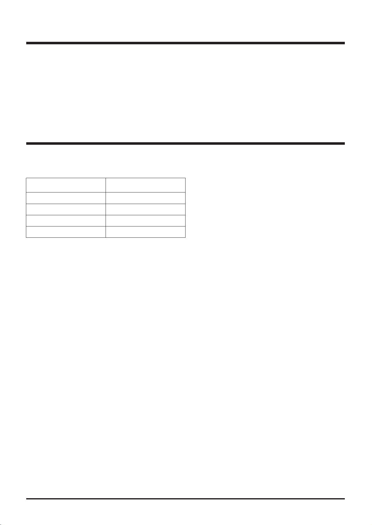
2. Applicable Models
● Lossnay (LGH-RX
3-E
)
These models have temperature sensors at RA and OA sides. It can automatically switch to the ventilation mode.
(Lossnay/By-pass)
Model
LGH-15RX3-E
LGH-25RX3-E
LGH-35RX3-E
LGH-50RX3-E
Model
LGH-80RX3-E
LGH-100RX3-E
LGH-150RX3-E
LGH-200RX3-E
● Lossnay Remote Controller (PZ-41SLB-E
)
Use when operating from 1 to 15 Lossnay units together at the same time. When using M-NET transmission to operate from
centralised control, use the PZ-52SF-E.
It can start and stop the unit, change fan speed, switch the ventilation mode. It also includes indicators that show errors and
when filter maintenance is required. Refer to page 63.
● Lossnay M-NET Remote Controller (PZ-52SF-E
)
It can be used in combination with Mitsubishi Electric Air conditioner Network system (MELANS). Refer to page 69. Since
this remote controller is supplied the power from the M-NET transmission line, it cannot be linked with Mr. Slim and other
such systems that do not use M-NET.
Please refer to the technical documentation for the other systems: City Multi, Mr. Slim
and the central controller (MELANS).
Page 5
2
3. Terminology
● Interlocked Lossnay
This is a Lossnay linked to City Multi, or Mr. Slim indoor units. This is a Lossnay that has been set to interlocked group setting to receive signals and operate via indoor unit’s remote controller → indoor unit → Lossnay.
● Non-interlocked Lossnay
This is a Lossnay that is not set to interlocked group setting with City Multi nor Mr. Slim indoor units. It operates using direct
operating signals from the Lossnay remote controller and/or centralised controller.
● Ventilation Mode
This mode controls the Lossnay damper and permits selection of heat recovery (Heat ex.), by-pass or auto modes.
● Delayed Operation
The Lossnay that has been set to interlocked group setting with the indoor unit will have its operation delayed for 30 minutes
after the operation of the indoor unit. When using PZ-41SLB-E, the time setting that can be set for delayed operation are 10,
20, 30, 40, 50, and 60 minutes.
● External Control Input
This is an input signal for operating the Lossnay that has been sent from an external device. It is compatible with 12V-24V
DC or uncharged a-contact signal.
● Operation Mode
This mode is used for selecting enabling/disabling of the on/off control signal from an external device and for setting interlocked operation of the external device and the Lossnay.
Please Refer to page 22 for details.
ON/OFF interlock: Enables both “ON → OFF” and “OFF → ON” external signals.
ON interlock: Enables “OFF → ON” external signal. Disables “ON → OFF” external signal.
OFF interlock: Enables “ON → OFF” external signal. Disables “OFF → ON” external signal.
External priority: Same as on/off interlock but the OFF signal from the remote controller is ignored when the
external control signal is on.
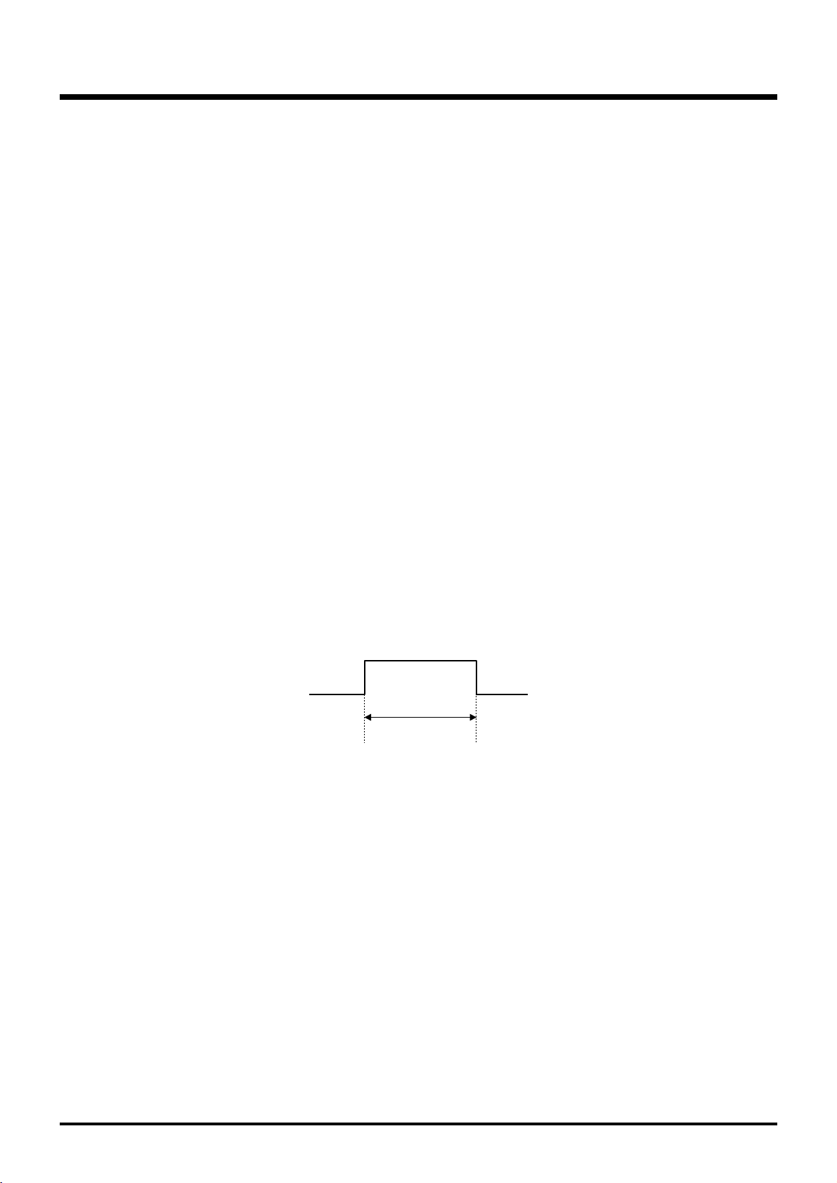
● Setting Pulse Input
When the control signal from the external device outputs a pulse such as the one shown below, pulse input setting is performed by the Lossnay. (Optional setting DIP switch 2-2 ON
)
200 ms or more
● Operation in Cold Areas
When the outdoor air is less than -10°C, continuous operation of the fan for drawing in supply air is cancelled, and intermittent operation is started.
● RA (Return Air
)
This is the abbreviation for return air, which is the air drawn in from indoor.
● OA (Outdoor Air
)
This is the abbreviation for outdoor air, which is the air drawn in from outdoor.
(
Page 6
3
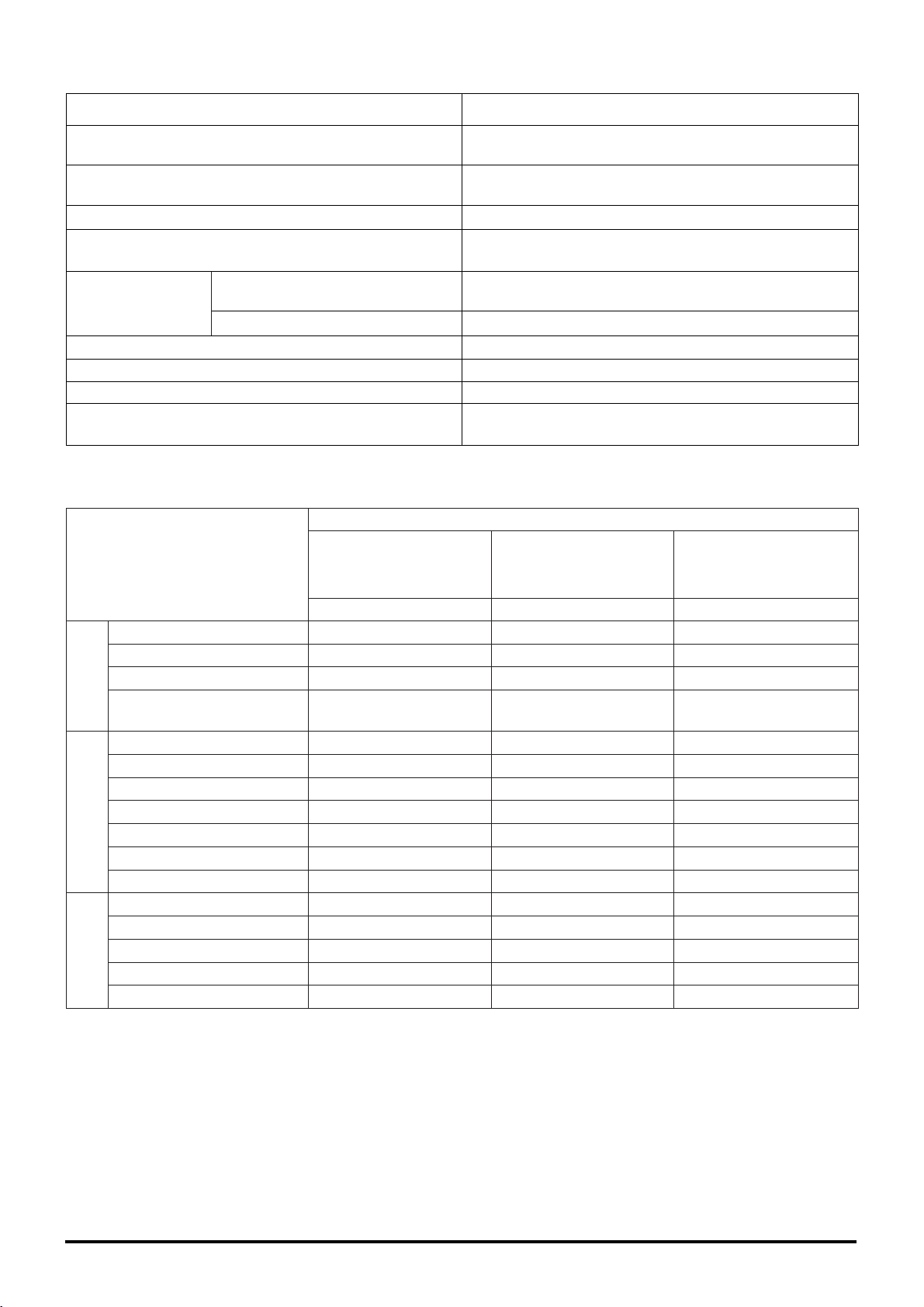
Classification
Control
Function
Installation
Maintenance
Item
• Multiple unit operation
• Remote controller operation
• External device operation
• External pulse control
• External monitor signal output
• Supply air fan monitor output
• External control operation mode setting
• Delayed start
• Automatic recovery following power supply interruption (*1)
• Power supply start/stop function
• High/low change input
• Remote/Local control change
• The M-NET air conditioning operation.
• Centralised control by Mitsubishi building
air control management system
• Interlocked with Mr. Slim
• Lossnay (heat recovery) ventilation/Bypass ventilation automatic switch
• For cold area operation
• Remote controller 2 wires wiring
(non-polar)
• Address setting unnecessary
• Test operation switch
• Filter maintenance display
(remote controller display)
• Inspection display
(remote controller, control board LED)
• M-NET power supply display
(control board LED)
Notes/Cautions
Maximum 15 units with PZ-41SLB-E; 16 units with PZ52SF-E or other M-NET controller.
Last touch priority
Signal form: 12VDC, 24VDC, uncharged a-contact
Ditto
Uncharged a-contact (external monitor/supply air fan
monitor change)
Ditto
ON/OFF , ON, OFF and External priority ON/OFF mode.
Delayed time can be varied only when the PZ-41SLB-E is
connected.
Return power automatic return is fixed when the PZ41SLB-E is connected.
Impossible when the PZ-41SLB-E is connected.
Uncharged a-contact (Part sold separately is necessary)
Uncharged a-contact (Part sold separately is necessary)
(Connection is impossible when using PZ-41SLB-E)
Only when M-NET transmission cable is connected
Ditto
Can not use the PZ-41SLB-E
When the PZ-41SLB-E is connected: PVC cable ø 0.65
to 1.2 or strand wire 0.3 mm
2
to 1.25 mm2.
When M-NET is connected: shielded wire or equivalent
1.25 mm
2
to 2.00 m2.
Excluding central controller system (except automatic
address)
For Lossnay single unit test operation
4. System Features and Examples
4.1 Features
*1 The operation condition is stored, and when the power is turned off and then back on, the operation condition returns to the
previous condition. (When using PZ-41SLB-E, the start/stop condition from an external device is not stored.)
Page 7
M-NET System
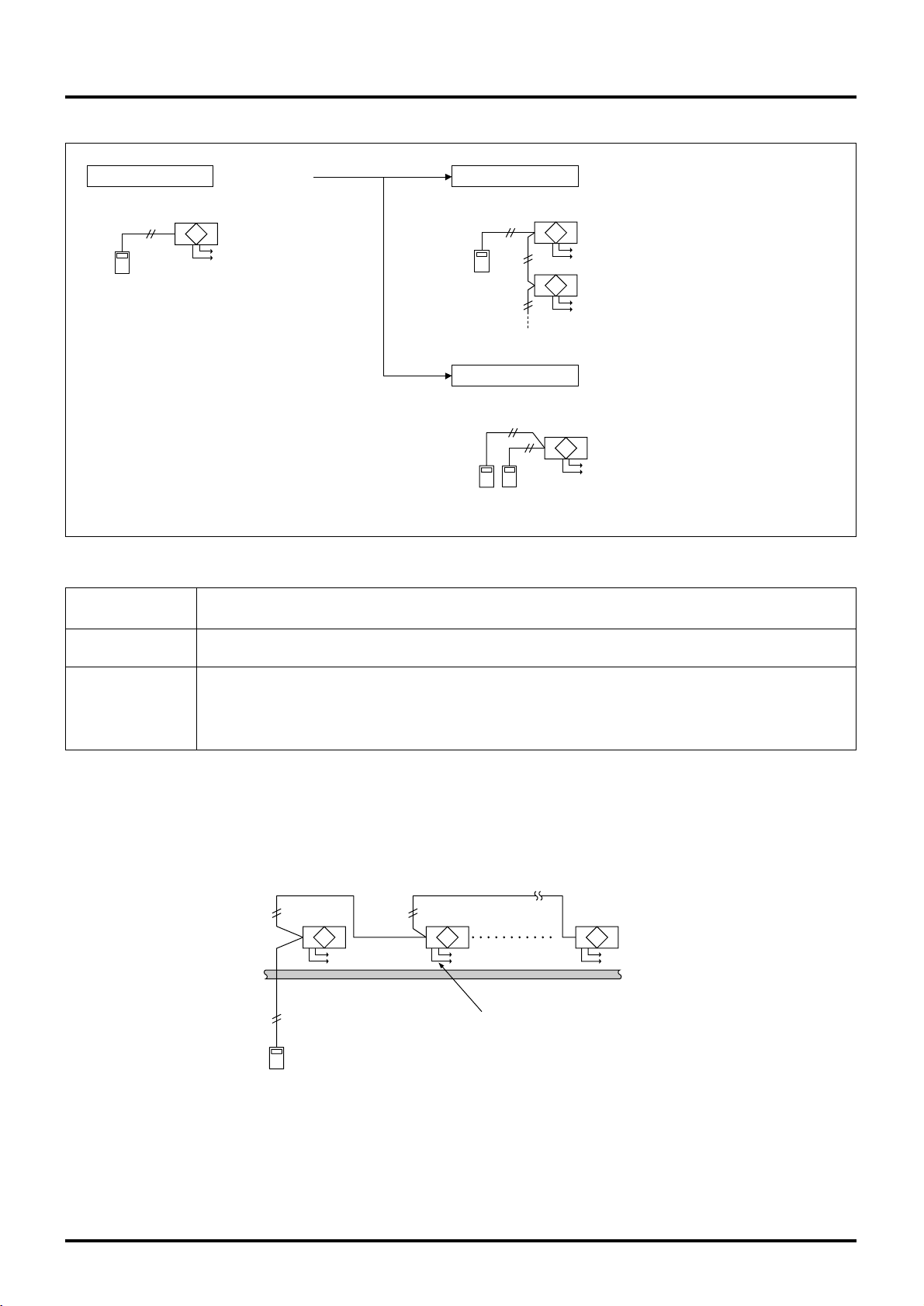
4.2 System Example
Operating with an external device
● The operation of the Lossnay will be connected with the operation or
stopping of the external device.
● Input of level signal or pulse signal (12V DC, 24V DC, uncharged acontact) is possible.
1 Lossnay with 1 remote controller
● This is a simple system.
A Lossnay is operated independently with 1
remote controller.
Multiple Lossnay units with 1 remote controller
● Up to 15 Lossnay units can be controlled at
one time with one remote controller. *
2 remote controller system with 1 Lossnay
● The Lossnay can be controlled from 2 remote
locations.
● The remote controller gives priority to the last
touch.
Operating with Mr. Slim (A-control or K-control)
● The Remote controller (A-control or K-control) controls the air conditioning device and the Lossnay.
● When using the A-control remote controller operating or switching fan
speed for the Lossnay individually is possible.
4
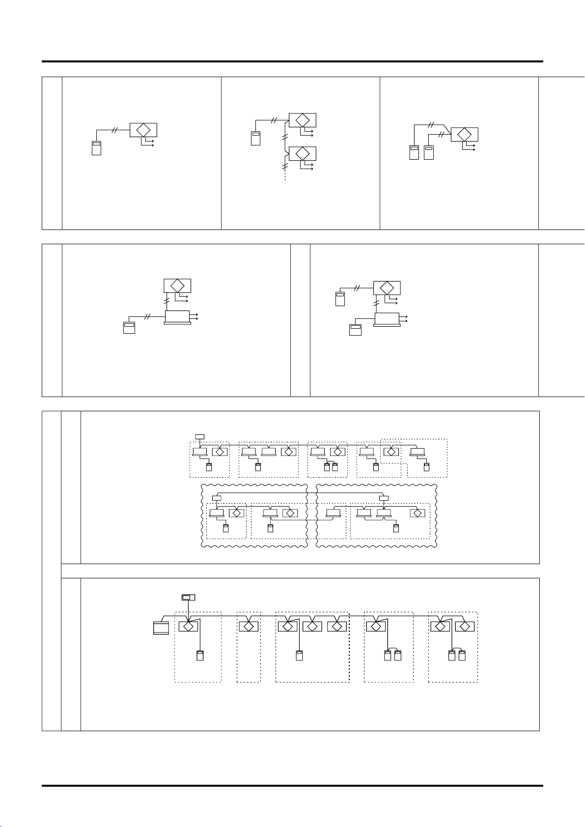
Basic System (refer to page 9)
Operation with an Air Conditioning Unit
(refer to page 12)
Operating with an External Device
(refer to page 21)
Lossnay
Non-polar
2 wires
Remote controller
PZ-41SLB-E
Power supply
Lossnay
Non-polar
2 wires
Power supply
Remote
controller
PZ-41SLB-E
(Sub)
(Main)
Lossnay
Power supply
Lossnay
Non-polar
2 wires
Remote controller
PZ-41SLB-E
Power supply
Air conditioning device and system control
● It is possible to operate 16 indoor units per 1 Lossnay
Indoor
unit
MA remote controller
Outdoor unit
Indoor
unit
MA remote controller
Lossnay
Indoor
unit
MA remote controller
Lossnay
Indoor
unit
Indoor
unit
MA remote controller
Indoor
unit
MA remote controller
Lossnay
Indoor
unit
MA remote controller
Indoor
unit
MA remote controller
Lossnay
Indoor unitIndoor unit
Group 1 Group 5Group 3 Group 4Group 2
Outdoor unit Outdoor unit
Indoor
unit
MA remote controller
Lossnay Lossnay
Group 1
Lossnay
Group 2 Group 3
Refrigerant 1 Refrigerant 2
● Control of start/stop, fan speed and ventiliation mode is possible from the Lossnay M-NET remote controller.
● Control of start/stop, fan speed and ventiliation mode is possible from the centralised controller.
● It is possible to set a maximum of 16 units for 1 group.
Lossnay M-NET
remote controller
PZ-52SF-E
Lossnay Lossnay
Group 1
Lossnay M-NET
remote controller
PZ-52SF-E
Lossnay Lossnay LossnayLossnay
Group 3
Lossnay M-NET
remote controller
PZ-52SF-E
Lossnay
Group 4Group 2
Centralised controller
Power
supply
unit
Lossnay M-NET
remote controller
PZ-52SF-E
Lossnay
Group 5
Lossnay
Power supply
Power supply
Remote
controller
Mr. Slim
(indoor unit)
Lossnay
Power supply
Power supply
Remote controller
Indoor unit
Remote controller
PZ-41SLB-E
Non-polar
two wires
City Multi and Lossnay Interlocked System
Centralised Management System
* In the case of LGH-150/200RX
3-E, there are 2 circuit boards installed in each unit, so count each unit as 2 Lossnay units.
● Selection of interlocked operation
mode is possible.
● Delayed start interlocked operation is
possible.
Page 8
Use Lossnay M-NET remote controller PZ-52SF-E .
(Do not use PZ-41SLB-E).
Lossnay transmission connection terminal
5
2 remote controller system with multiple Lossnay units
● It is also possible to operate 2 remote controller units when using multiple Lossnay units.
Power supply
Power supply
Remote controller
PZ-41SLB-E
Interlocking multiple units
When the operation signal is a uncharged a-contact signal
Interlocking/individual joint systems
By making the group setting, interlock settings have become possible.
(Joint use of the air conditioner remote controller and Lossnay remote
controller is possible.)
● Interlocking is possible from multiple air conditioning units, etc.
(excluding pulse input)
(Separately sold parts are necessary depending on the operation signal).
● Applicable indoor units are C type or later (for use with MA remote controller) models
● Do not set the air conditioning unit and Lossnay unit to be part of the
same group.
When the address number has been changed, the data in the memory is
automatically reset.
Power suupy Power suupy Power suupy Power suupy
Lossnay
A/C A/C A/C
Remote
controller
PZ-41SLB-E
Air conditioning
unit side remote
controller
Air conditioning
unit side remote
controller
Air conditioning
unit side remote
controller
Indoor unit
(01)
Centralised
controller
(201)
Outdoor
unit (51)
Operation settings
MA remote
controller
Lossnay (02)
Lossnay M-NET
remote controller
(PZ-52SF-E)(102)
Group 1 Group 2
Use Lossnay remote controller PZ-41SLB-E .
(Do not use PZ-52SF-E).
Lossnay transmission connection terminal
ABS65654321
Transmission cable
Transmission
cable
Round terminal
M-NET Transmission cable
input terminal block
Shielded wire
M-NET
Transmission cable
Remote Controller Input Terminal
Main/Sub switch (SW1)
Main Sub
(Set to Main when
shipped from the factory)
( ) address
LGH-15 to 100RX3 LGH-150 and 200RX3
LGH-15 to 100RX3
TB5
LGH-150 and 200RX
3
TB5
Setting
Setting
LGH-15 to 100RX
3 LGH-150 and 200RX3
Upper
circuit
board
[Sub]
ex. SA1 = 0,
SA2 = 2
Lower
circuit
board
[Main]
ex. SA1 = 0,
SA2 = 1
ABS A65BS
SA1 SA1
0
1
2
0
SA1 SA2SA1 SA2
1
0
Page 9
6
4.3 System Selection
Interlocked with City Multi
(
Refer to page 16
)
Lossnay operation when indoor unit is stopped ●●
Lossnay stopping when indoor unit is operating ●●
Switching Lossnay fan speed
When interlocked with indoor unit for compatibility with both R22 and R407C
High/Low
When interlocked with indoor unit for other than the above
Fixed to high
Ventilation mode
Fixed to automatic
Filter maintenance indicator ●●
Lossnay error indicator ●●
Delayed operation ●●
External control operating mode selection ×
Number of indoor units for interlocked group setting with one Lossnay unit
16 units
Number of Lossnay units for interlocked group setting with one indoor unit
1 unit
Interlocked with external device (BMS
)
(
Refer to page 21
)
Start/Stop ●●
Fan speed switching
Fixed to high
Ventilation mode switching
Fixed to automatic
Filter maintenance indicator ×
Lossnay error indicator ×
Delayed operation ●●
External control operating mode selection ●●
Lossnay unit
LGH-RX3-E
M-NET transmission cable
Remote controller
City Multi
indoor unit
Interlocked with Mr. Slim
(
Refer to page 12
)
When using A-control remote controller
Lossnay operation when indoor unit is stopped ●●
Lossnay stopping when indoor unit is operating ×
Lossnay fan speed switching High/Low
When using K-control controller
Lossnay operation when indoor unit is stopped ×
Lossnay stopping when indoor unit is operating ×
Lossnay fan speed switching
Fixed to high
Other common items
Lossnay error indicator ×
Ventilation mode
Fixed to automatic
Filter maintenance indicator ×
Delayed operation ●●
External control operating mode selection ×
Number of indoor units for interlocked group setting with one Lossnay unit
1 unit
Number of Lossnay units for interlocked group setting with one indoor unit
1 unit
Slim-Lossnay connecting cable
(
Enclosed accessory
)
Remote controller
Mr.Slim (A, K-control
)
indoor unit
Lossnay remote
controller
cannot be used.
Lossnay unit
LGH-RX3-E
Independent Lossnay Unit
(
Not interlocked with
City Multi or Mr. Slim systems.
)
(
Refer to page 9
)
Start/Stop ●●
Fan speed switching High/Low
Ventilation mode
Heat ex. /
By-pass/ Auto
Filter maintenance indicator ●●
Lossnay error indicator ●●
Delayed operation ●●
External control operating mode selection ●●
Number of Lossnay units
15 units
(
In the case of LGH-150/200RX3-E, count each unit as two for calcultion)
Number of remote controllers 2 units
Lossnay remote controller
(PZ41SLB-E)
EXT. signal source
for interlocking
to the Lossnay
Lossnay unit
LGH-RX3-E
EXT. signal source
for interlocking
to the Lossnay
Lossnay unit
LGH-RX3-E
Page 10
7
Central Con-
troller Sys-
tem
Central Controller System
Centralised Controller
Power supply unit
PAC-SC34KUA
Indoor unit
Lossnay
Indoor unit
Outdoor unit
A-control Mr.Slim outdoor unit
Mr.Slim A-control
remote controller
A-control
Mr.Slim indoor unit
Lossnay
Lossnay M-NET
remote controller
(PZ-52SF-E)
EXT.
signal
source
Lossnay M-NET
remote controller
(PZ-52SF-E)
Remote controller
K-transmissoin
converter
Remote controller
Mr.Slim K-control
remote controller
K-control
Mr.Slim indoor unit
Lossnay
LossnayLossnay
Lossnay M-NET
remote controller
(PZ-52SF-E)
Lossnay
Caution:
● Lossnay remote controller PZ-41SLB-E can not be used.
Page 11
8
Reference: Remote controller for the Lossnay and indoor unit.
Refer to the technical documentation related to the Remote controller for the indoor unit.
Remote controllers for City Multi indoor unit
Network remote controller (PAR-20MAA
)
Simple remote controller (PAR-27MEA
)
TIMER SET
PAR-20MAA
ON/OFF
CENTRALLY CONTROLLED
ERROR CODE
CLOCK
ON OFF
ßC
CHECK
CHECK MODE
FILTER
TEST RUN
FUNCTION
ßC
1Hr.
NOT AVAILABLE
STAND BY
DEFROST
FILTER
CHECK TEST
TEMP.
With Lossnay interlock switches and indicators.
PAR-F27MEA
ON/OFF
CENTRALLY CONTROLLED
DAILY
AUTO OFF
REMAINDER
CLOCK
ON OFF
ßC
CHECK MODE
FILTER
TEST RUN
LIMIT TEMP.
ßC
1Hr.
NOT AVAILABLE
STAND BY
DEFROST
FILTER
CHECK TEST
TEMP.
TIMER SET
CLOCK→ON→OFF
Without Lossnay interlock switches and indicators.
Remote controllers for Mr. Slim indoor unit
A-control remote controller (PAR-27AA
)
K-control remote controller
ON/OFF
–
STAND BY
DEFROST
INDOOR UNIT
ADDRESS NO.
ERROR CODE
OA UNIT ADDRESS NO.
CENTRALLY CONTROLLED
CLOCK
ON OFF
˚C
1Hr.
NOT AVAILABLE
˚C
CHECK MODE
FILTER
CHECK
TEST RUN
ON OFFCLOCK
FILTER
CHECK
TEST RUN
REMOTE CONTROLLER
TEMP. TIMER SET
With Lossnay interlock switches and indicators.
ON/OFF
–
STAND BY
DEFROST
CENTRALLY CONTROLLED
CLOCK
ON OFF
˚C
1Hr.
NOT AVAILABLE
CHECK MODE
FILTER
CHECK
TEST RUN
ON OFFCLOCK
FILTER
CHECK
TEST RUN
REMOTE CONTROLLER
TEMP. TIMER SET
˚C
Without Lossnay interlock switches and indicators.
Remote controllers for Lossnay unit
Lossnay remote controller (PZ-41SLB-E) Lossnay M-NET remote controller (PZ-52SF-E)
DELAYSTART
FILTER
PZ-41SLB-E
2CONTROLLERS
BY-PASS
CHECK
SETTING
FILTER
MIN.DELAYED
AUTO
HEATEX.
INTERLOCKED
With Lossnay interlock switches and indicators.
CENTRAL
HEAT EX.
BY-PASS
AUTO
CHECK
INTERLOCKED
FILTER
ON/OFF
NOT
AVAILABLE
FILTER
Without Lossnay interlock switches and indicators.
Page 12
9
4.4 Basic System
4.4.1 System Summary
4.4.2 Operation of Multiple Units
Design Example 1 Basic system
● This is a simple system.
A Lossnay is operated independently
with 1 remote controller.
Lossnay
Non-polar
2 wires
Remote controller
PZ-41SLB-E
Power supply
Design Example 2 Lossnay control of multiple units
● Up to 15 Lossnay units can be
controlled at one time with 1
remote controller switch.
(up to 7 units when using LGH150/200RX
3)
Lossnay
Non-polar
2 wires
Power supply
Remote
controller
PZ-41SLB-E
(Sub)
(Main)
Lossnay
Power supply
Design Example 3 2 remote controller system
● The Lossnay can be controlled
from 2 remote locations.
● The remote controller gives priority to the last touch.
Lossnay
Non-polar
2 wires
Remote controller
PZ-41SLB-E
Power supply
Feature
For LGH-15 to 100RX
3, 1 remote controller can operate from 1 to 15 Lossnay units. For using LGH-
150/200RX3, 1 remote controller can operate from 1 to 7 Lossnay units.
Ordered part
Remote controller
PZ-41SLB-E
• Also connect the power to the second and following Lossnay units.
Notes
• The maximum extension of the transmission cable is 500 m or less (between Lossnay and remote
controller switch, between Lossnay and Lossnay).
• The main or Sub setting on the Lossnay is necessary.
Note:
● The external device operation signal, and pulse signals can only be connected to the Lossnay on the “Main” setting.
● When the M-NET system is connected, do not connect the transmission cable to TM2.
System Example
Lossnay
(Main)
Power supply
(Transmission cable
extension is 500 m or less)
PVC cable ø0.65 to 1.2 or
strand wire 0.3 mm
Remote controller
PZ-41SLB-E
2
to 1.25 mm2.
Lossnay
(Sub)
Power supply
Lossnay
(Sub)
up to
15 units
(Be sure to turn on the
power for the second and
following Lossnay units.)
Power supply
Page 13
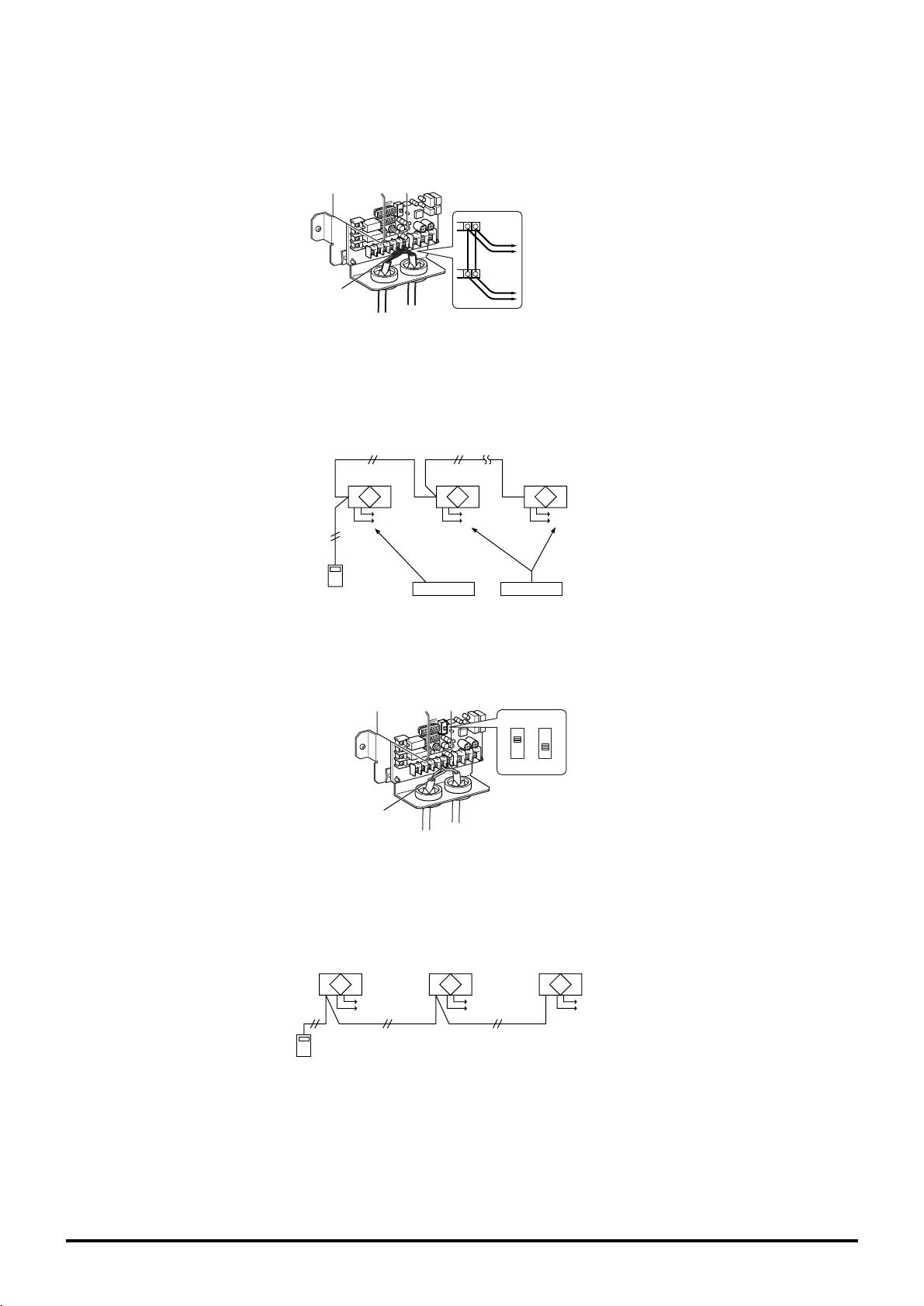
10
Combined Line Method
Connect the transmission cable from the first Lossnay to the second, the second to the third, and so on up to a maximum of 15
units.
(1) Up to four wires can be connected to one signal terminal when a transmission cable is ø0.65 or strand wire 0.3 mm
2
, or up
to 2 wires in other cases.
(2) The signal is non-polar, so it is not necessary to align polarity.
65
65
Lossnay
Power supply
Lossnay
Power supply
Lossnay
Power supply
Remote
controller
PZ-41SLB-E
Set to Main Set to Sub
Main/Sub selection switch
(SW1)
Main Sub
Transmission
cable
Transmission
cable
Connect to
remote controller
(PZ-41SLB-E)
Connect to third
Lossnay
Lossnay Main/Sub Setting
Be sure to make the Main/Sub setting when operating multiple Lossnay units.
When operating multiple Lossnay units, set the first one to “Main,” set the second and following to “Sub.”
Be sure the power is off when making the settings.
Change the Main/Sub switch (SW1) on the control board to “Sub” for the second and following Lossnay units.
Operation Method
Up to 15 Lossnay units (up to seven units when using LGH-150/200RX3-E) can be operated when running at the same time.
(Individual control is not possible)
Note:
● In the case of LGH-150/200RX3-E, there are two circuit boards installed in each unit. Therefore, count each unit as two units
in calculations when controlling multiple units. For example, 5 LGH-150RX
3-E units would count as 10 units. (For
150/200RX3-E type only, a maximum of seven units is possible.)
(Main)
Lossnay
(Sub)
Lossnay
(Sub)
Lossnay
Power supply Power supply Power supply
Remote controller
PZ-41SLB-E
Page 14
11
4.4.3 Operation with 2 Remote controllers
System Example
Operation Method
(1) When there are 2 remote controllers, “2 CONTROLLERS” will display on the LCD readout’s upper region.
(2) The operation is the same with each remote controller. In this case, the Lossnay gives operating priority to the last button
push.
Characteristics
Remote controller
Note
• Lossnay can be operated from two remote locations. • Use only up to 2 remote controller
• Lossnay conditions can be checked from two remote Lossnay remote controller (Operation will not go normally if 3
locations. PZ-41SLB-E remote controller switches are con
• The remote controller gives priority to the last touch. nected.)
Lossnay
Power supply
Lossnay
Power supply
Transmission
cable extension
is 500 m or less
PVC cable
ø0.65 to 1.2 or
strand wire
0.3 mm2 to 1.25 mm2.
Remote controller
PZ-41SLB-E
Transmission
cable extension
is 500 m or less
PVC cable
ø0.65 to 1.2 or
strand wire
0.3 mm2 to 1.25 mm2.
Lossnay up to 15 units,
or 7 units for LGH 150/200 type
(Be sure to turn on the power for the
second and following Lossnay units.)
Lossnay
Power supply
Lossnay
Power supply
Lossnay
Power supply
Lossnay
Power supply
Remote
controller
PZ-41SLB-E
Remote
controller
PZ-41SLB-E
Remote controller
PZ-41SLB-E
Lossnay up to 15 units,
or 7 units for LGH 150/200 type
(Be sure to turn on the power for the
second and following Lossnay units.)
Lossnay
2CONTROLLERS
BY-PASS
AUTO
HEAT EX.
Remote
controller
Remote
controller
Close-up of
display region
Page 15
12
4.5 Interlocking with Mr. Slim
4.5.1 Interlocked Mr. Slim and Lossnay System
Features
● Interlocked operation with Mitsubishi air-conditioners is possible.
System Example
Slim-Lossnay
connection cable
(
Enclosed accessory
)
A-control or K-control
Mr.Slim indoor unit
A-control or K-control
Mr.Slim outdoor unit
A-control or K-control
remote controller
Lossnay unit
LGH-RX
3-E
Lossnay Function Table (Interlocked settings
)
Item
Number of indoor units that can be set to interlocked operation with 1 Lossnay unit in each group
Number of Lossnay units that can be set to interlocked operation with 1 indoor unit
Operation of Lossnay unit only
(
When indoor unit is stopped
)
A-control
K-control
Independent Lossnay unit start and stop
(
When indoor unit is operating
)
A-control
K-control
Delayed operation
(
Optional setting
)
Fan speed switching A-control
K-control
Ventilation mode
Filter indicator
Error
Restrictions and precautions
Details
1 unit
1 unit
Possible
Not possible
Not possible
Not possible
30 minute delayed operation when indoor unit cooling/heating
is started
High/Low
Fixed to high
Fixed to automatic
Not possible
Not possible
* The Lossnay remote controller cannot be used on systems
interlocked with Mr. Slim.
When connecting a PZ-41SLB-E to a Lossnay unit,
ON/OFF and High/Low operation by the PZ-41SLB-E cannot be reflected to the display of the Mr. Slim’s A-control
remote controller.
Page 16
13
Controller Function Table especially regarded to the Lossnay unit
Lossnay remote
controller
PZ-41SLB-E, PZ-52SF-E
K-control
remote
controller
«
×
× (Automatic)
×
«
×
×
×
×
×
×
A-control remote
controller
PAR-S27AA
«
«
× (Automatic)
×
«
«
×
×
×
×
×
Local Remote
Model
Start/Stop
Fan speed switching
Ventilation mode switching
Priority instructions. Local
permitted/prohibited
Status (Operation/Stop
)
Fan speed switching
Ventilation mode
Error
Error content
Filter sign
Local permitted/prohibited
Not used to the interlocked
Lossnays
Monitoring Operation
Switched and display
«
: Group only (or function available)× : Not available
● For details about the operation or display of the A-control remote controller (PAR-27AA), refer to page 81.
Page 17
14
4.6 Combination with City Multi
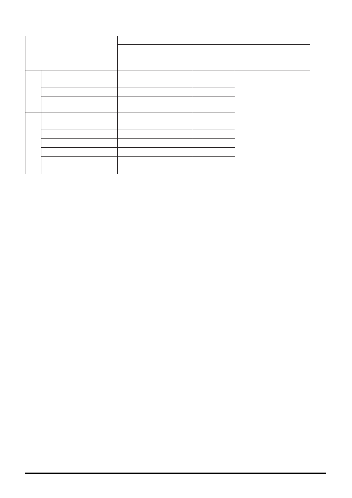
4.6.1 Independent Lossnay System with Lossnay M-NET Remote
Controller and MELANS
Features
● The Mitsubishi Electric air-conditioner network system (MELANS)can operate and monitor each group of Lossnay units and
air-conditioners.
● Can also perform operations using Lossnay M-NET remote controller.
System Examples: 1
The following groups can be configured.
Lossnay
(001)
Centralised controller
(
000
)
Power
supply
unit
Lossnay M-NET remote
controller PZ-52SF-E
(106)
(103)
( )
address
Group1
Group6
Group2 Group3 Group4 Group5
Lossnay M-NET remote
controller PZ-52SF-E
(156)
(101)
Lossnay
(013)
Group8
Lossnay M-NET remote
controller PZ-52SF-E
(114)
Lossnay
(014)
Lossnay
(015)
Lossnay
(002)
Lossnay
(004)
Lossnay
(005)
Lossnay
(006)
Lossnay
(003)
Lossnay
(010)
Lossnay
(008)
Lossnay M-NET remote
controller PZ-52SF-E
(107)
(157)
Lossnay
(007)
Lossnay M-NET remote
controller PZ-52SF-E
Indoor
unit
(009)
MA Remote
controller
Group7
Indoor
unit
(011)
Indoor unit
(012)
MA Remote
controller
Group9
Indoor
unit
(016)
MA Remote
controller
Outdoor unit
(059)
Group 1 : Group of 1 Lossnay unit and 1 Lossnay M-NET remote controller.
Group 2 : Group without Lossnay M-NET remote controller.
Group 3 : Group of multiple Lossnay units and 1 Lossnay M-NET remote controller.
Group 4 : Group of 1 Lossnay unit and 2 Lossnay M-NET remote controllers.
Group 5 : Group of multiple Lossnay units and 2 Lossnay M-NET remote controllers.
Group 6 : Group of 1 indoor unit and 1 Lossnay unit in interlocked operation.
Group 7 : Group of multiple indoor units and 1 Lossnay unit in interlocked operation.
Group 8 : Group of multiple Lossnay units connected to 1 indoor unit transmission cable and 1 Lossnay M-NET
remote controller.
Group 9 : Group with no Lossnay units.
Caution:
● Lossnay remote controller PZ-41SLB-E can not be used.
Page 18
15
Lossnay Function Table (Group Setting
)
Controller Function Table
Item
Number of Lossnay remote controllers and/or MELANS
units that can be connected to 1 Lossnay unit
Operation of 2 remote controllers in 1 group
Fan speed switching
Ventilation mode
Filter indicator
Error
Details
5 units
(
Number of Lossnay remote controller is 2 units max.
)
Possible
High/Low
Heat ex. / By-pass / Automatic
3000 hours / 1500 hours / 4500 hours / No display
Display
Centralised
controller
MJ-180A
100 Groups/
100 Units
*200 Groups/
200 Units
n
«
n
n
«
«
«
«
«
«
«
«
6
42
1
«
Centralised
controller
MJ-103MTRA
50 Groups/
50 Units
n
n
n
n
«
«
«
«
«
«
«
«
3
21
10
«
MA remote
controller
PAR-20MAA
ME remote
controller
PAR-F27MEA
Lossnay M-
NET remote
controller
PZ-52SF-E
1 Group/
16 Units
«
«
«
×
«
«
«
«
«
«
«
×
×
×
×
×
No. of controllable (Groups/Units
)
Local Remote
Model
MELANS Series
Start/Stop
Fan speed switching
Ventilation mode switching
Priority instructions. Local
permitted/prohibited
Status (Operation/Stop
)
Fan speed switching
Ventilation mode
Error
Error content
Filter sign
Local permitted/prohibited
Weekly
Stop/Starts per day
Stop/Starts per week
Minimum setting (minutes
)
Error record
Scheduling/
Recording
Monitoring
Operation
Switches and display
n
: Group/batch
«
: Group only (or function available
)
× : Not available
* Can be expanded to 200 units by using 2 gateway units.
● For details about the operation or display of the Lossnay M-NET remote controller (PZ-52SF-E) refer to page 69.
● For details about the operation or display of the Centralised controller (MJ-103MTRA) refer to page 74.
Not used to
the non-interrocked Lossnay
Page 19
16
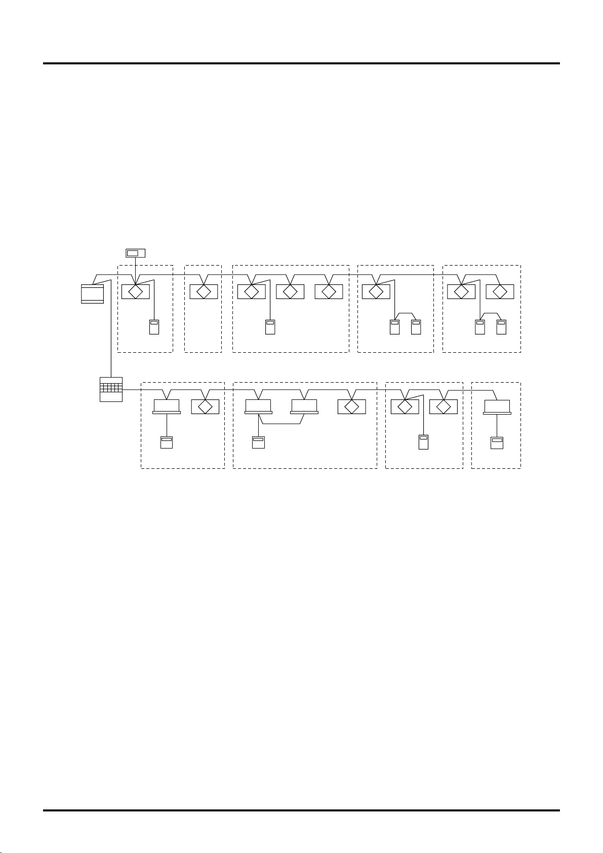
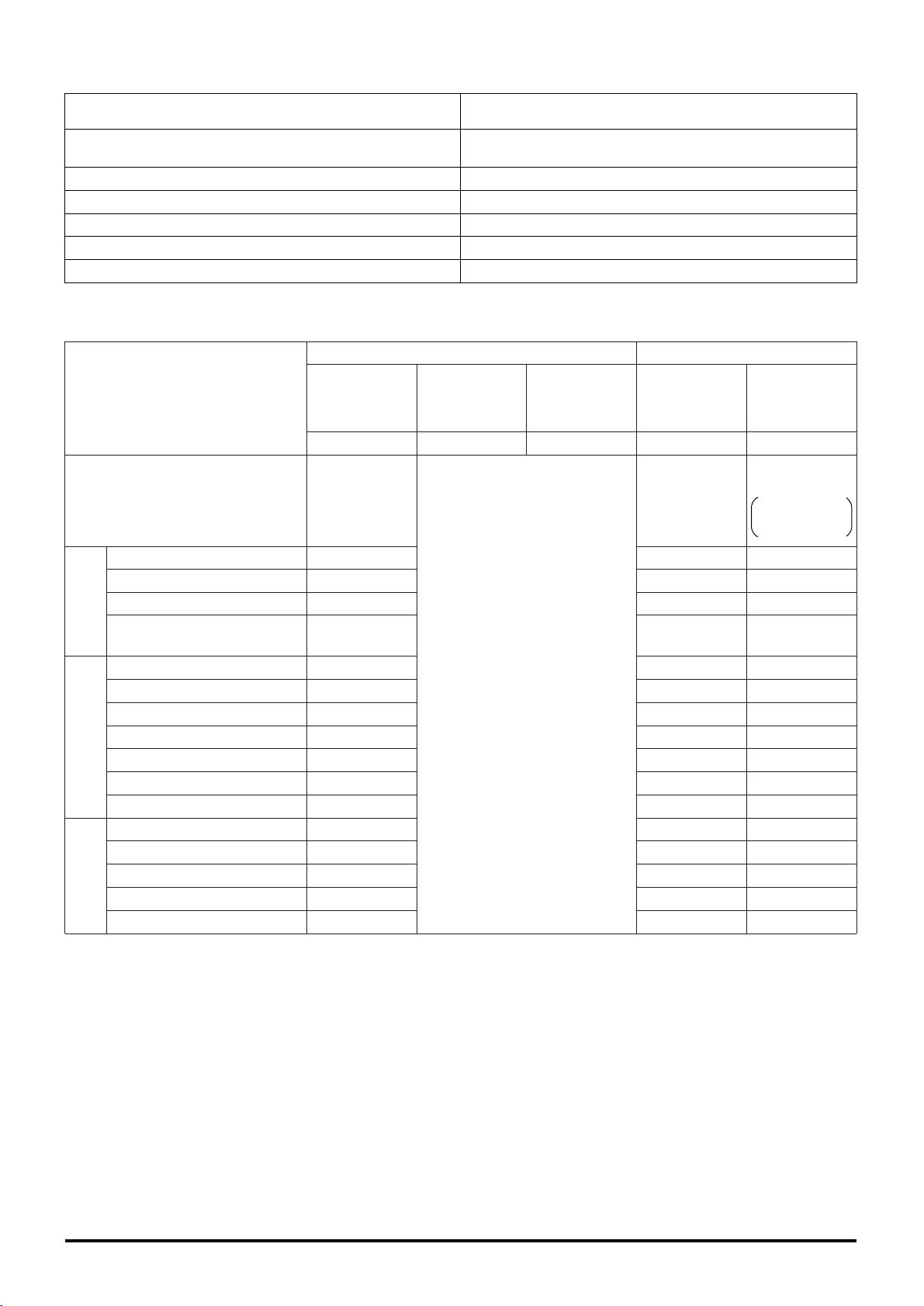
4.6.2 City Multi and Lossnay Interlocked System
Characteristics
● Interlocked operation with Mitsubishi air-conditioners is possible.
● Can also perform independent Lossnay operations using MA remote controller or ME remote controller.
System Examples
The following groups can be configured.
Single Refrigerant System
Group1
Lossnay
(005)
Group3
Lossnay
(007)
Lossnay
(009)
Lossnay
(002)
Indoor
unit
(001)
MA Remote
controller
Indoor
unit
(010)
MA Remote
controller
Group2
Indoor
unit
(003)
Indoor unit
(004)
MA Remote
controller
Group4 Group5
Indoor
unit
(006)
Indoor
unit
(008)
MA Remote
controller
MA Remote
controller
Outdoor unit (051)
( ) address
Lossnay remote controller PZ-41SLB-E
can not be used with any group.
Multiple Refrigerants System
Group1
Lossnay
(004)
Group3
Lossnay
(008)
Lossnay
(002)
Indoor
unit
(001)
MA Remote
controller
Group2
Indoor
unit
(003)
Indoor unit
(005)
Indoor unit
(007)
MA Remote
controller
Indoor
unit
(006)
MA Remote
controller
Outdoor unit (051) Outdoor unit (055)
( ) address
Refrigerant 1 Refrigerant 2
Group 1 : Group of 1 indoor unit and 1 Lossnay in interlocked operation.
Group 2 : Group of multiple indoor units and 1 Lossnay unit in interlocked operation.
Group 3 : Group of 1 indoor unit with 2 remote controllers and 1 Lossnay unit in interlocked operation.
Group 4, 5 : Group of multiple groups and 1 Lossnay unit in interlocked operation.
Group 1 : Group of 1 indoor unit and 1 Lossnay in interlocked operation.
Group 2 : Group of multiple indoor units (with different refrigerants) and 1 Lossnay unit in interlocked operation.
Group 3 : Group of multiple indoor units (with same refrigerant) and 1 Lossnay unit in interlocked operation.
Page 20
17
Lossnay Function Table (Interlocked Settings)
Controller Function Table especially regarded to the Lossnay unit
Item
Number of indoor units that can be set to interlocked operation with 1 Lossnay unit in each group
Number of Lossnay units that can be set to interlocked operation with 1 indoor unit
Independent start/stop of ventilation (Lossnay)
Delayed operation
(Optional setting)
Fan speed switching Indoor unit compatible with both R22
and R407C
Units other than the above
Ventilation mode
Filter maintenance indicator
Error
Restrictions and precautions
Details
16 units per group
1 unit
Possible
30 minute delayed operation when indoor unit cooling/heating is started
High/Low
Fixed to high
Fixed to automatic
3000 hours / 1500 hours / 4500 hours / No display
Display
* Lossnays cannot be interlocked to the indoor units using K-
transmission converter.
MA remote
controller
PAR-20MAA
«
«
× (Automatic)
×
«
«
×
«
«
«
«
×
2
×
10
×
ME remote
controller
PAR-F27MEA
«
«
× (Automatic)
×
«
«
×
«
«
«
«
× (Dayly)
2
×
10
×
Lossnay
M-NET remote
controller
PZ-52SF-E
«
«
«
×
«
«
«
«
«
«
«
×
×
×
×
×
Local Remote
Model
Start/Stop
Fan speed switching
Ventilation mode switching
Priority instructions. Local
permitted/prohibited
Status (Operation/Stop
)
Fan speed switching
Ventilation mode
Error
Error content
Filter sign
Local permitted/prohibited
Weekly
Stop/Starts per day
Stop/Starts per week
Minimum setting (minutes
)
Error record
Scheduling/
Recording
Monitoring Operation
Switches and display
«
: Function available × : Not available
●
For details about the operation or display of the remote controller (PAR-F27MEA, PAR-20MAA), please refer to those Manuals.
Page 21
18
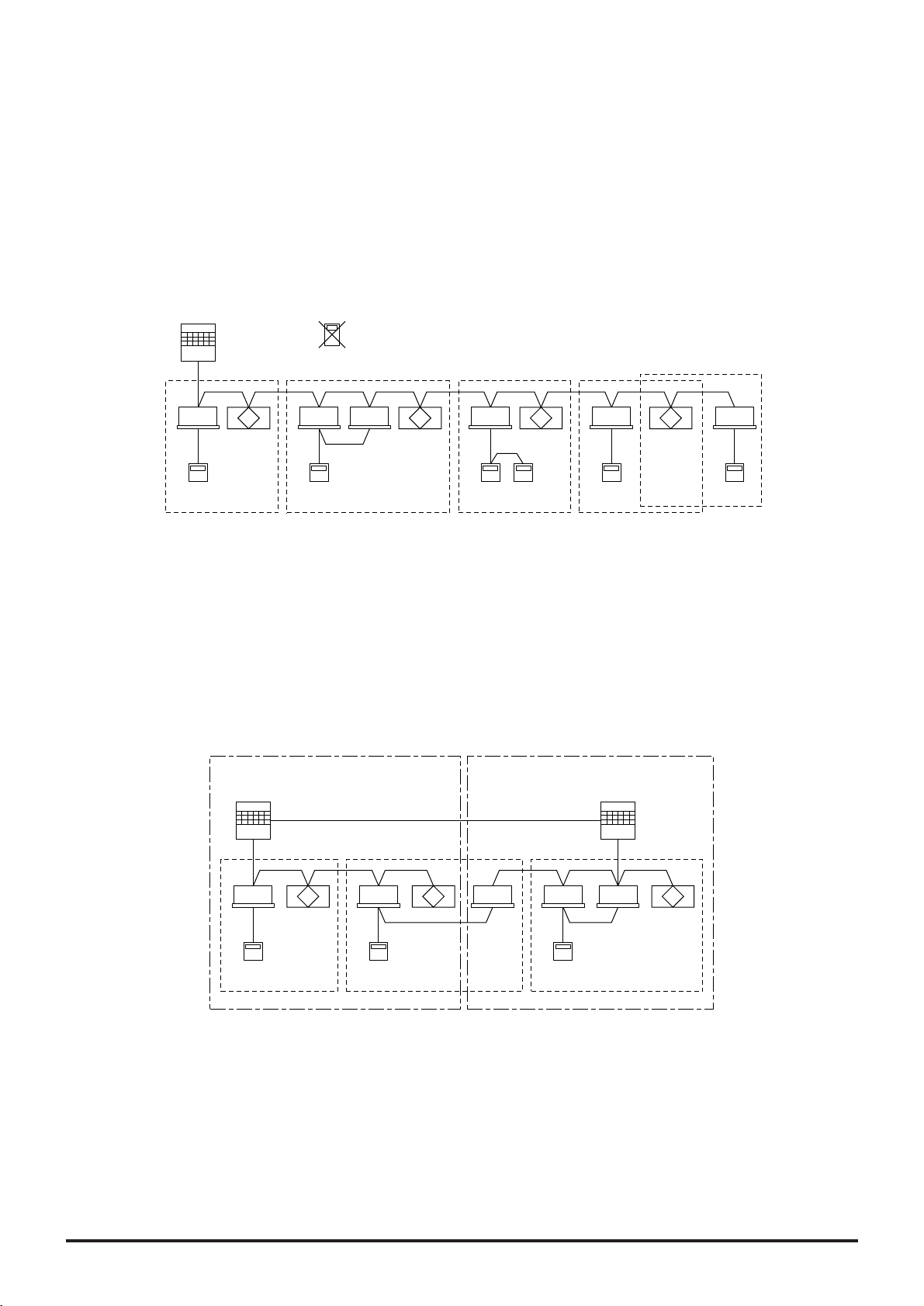
4.6.3 MA Remote Controller/ME Remote Controller in Combination
with Lossnay M-NET Remote Controller
System
The MA remote controller, ME remote controller, and Lossnay M-NET remote controller can be used in combination.
Combination of Air Conditioner Remote Control and Lossnay Remote Control
Indoor
unit (001)
Lossnay
(002)
Lossnay M-NET
remote controller
PZ-52SF-E (102)
MA remote
controller
(101)
Centralised
controller
(201)
Outdoor unit
(051)
Power
supply
unit
Group1 Group2
Interlocked operation setting
( ) address
Indoor Unit Lossnay LGH-RX3-E
Model for MA remote control (Type C or later) «
Model for other than MA remote control (Type B or earlier) ×
«
: Compatible × : Incompatible
System Examples: 1
Setting Method
(1) Make the Group setting for the indoor unit.
(2) Make the Group setting for the Lossnay unit.
(3) Set the indoor unit and Lossnay unit in interlocked operation.
When using the centralised controller, make both the Group setting and operation setting for the previously mentioned units.
Though the MJ-180A cannot set interlocked settings, it should set at MA/ME remote controllers.
Characteristics
(1) When the indoor unit is set for interlocked operation in 1 group:
Interlocked operation with the indoor unit from the air conditioner remote controller is possible and can switch between
High/Low/Off.
From the air conditioner remote controller it is possible to switch the Lossnay only between High/Low/Off.
From the Lossnay remote controller it is possible to switch the Lossnay between High/Low/Off.
(2) When the 2 or more indoor units with different group are set for interlocked operation, the Lossnay will operate if at least 1
group operates. The Lossnay will stop operation if all groups stop operation.
From an air conditioner remote controller it is possible to switch the Lossnay only between High/Low when other groups are
operating.
From the Lossnay remote controller it is possible to switch the Lossnay between High/Low/Off.
Note:
● If the display on the MA remote controller/ME remote controller, or other air conditioner remote controller, is cancelled, the air
conditioner remote controller will not show the ventilation display even if you operate the Lossnay from the Lossnay M-NET
remote controller.
Note:
Transmission cable power control for indoor units
Be sure usage is within the following boundaries.
● Indoor units + ME remote controllers (compact remote controllers) + Lossnay M-NET remote controllers is less than or equal
to 40 units.
● Indoor units are less than or equal to 20 units.
(The numbers of MA remote controllers and Lossnay units are not included in the above number of units.)
Page 22
19
System Examples: 2
A mixed system including the City Multi can also be configured.
Note:
● Do not use Lossnay remote controller PZ-41SLB-E in case of a system using M-NET transmission cable.
(
109
)
(
103
)
(
106
)(
107
)
(
157
)
(
111
)
(
114
)
(
116
)
Indoor unit
(011)
Group1 Group2
Group6 Group7 Group8 Group9
Group3 Group4 Group5
Centralised controller (000
)
Outdoor unit
(
059
)
Power
supply
unit
Lossnay M-NET remote
controller PZ-52SF-E
Lossnay M-NET remote
controller PZ-52SF-E
Lossnay M-NET remote
controller PZ-52SF-E
Lossnay M-NET remote
controller PZ-52SF-E
Lossnay M-NET remote
controller PZ-52SF-E
ME
remote controller
ME
remote controller
ME
remote controller
( )
address
(
101
)
(
156
)
Lossnay
(001)
Lossnay
(010)
Lossnay
(013)
Lossnay
(014)
Lossnay
(015)
Lossnay
(002)
Lossnay
(003)
Lossnay
(004)
Lossnay
(005)
Lossnay
(006)
Lossnay
(007)
Lossnay(008)
Indoor unit
(009)
Indoor unit
(012)
Indoor unit
(016)
Group 1 : Group of 1 Lossnay unit and 1 Lossnay M-NET remote controller.
Group 2 : Group with no Lossnay M-NET remote controller.
Group 3 : Group of multiple Lossnay units and 1 Lossnay M-NET remote controller.
Group 4 : Group of 1 Lossnay unit and 2 Lossnay M-NET remote controllers.
Group 5 : Group of multiple Lossnay units and 2 Lossnay M-NET remote controllers.
Group 6 : Group of 1 indoor unit and 1 Lossnay unit in interlocked operation.
Group 7 : Group of multiple indoor units and 1 Lossnay unit in interlocked operation.
Group 8 : Group of multiple Lossnay units connected to an indoor unit transmission cable and 1 Lossnay M-NET
remote controller.
Group 9 : Group with no Lossnay units.
Lossnay
(01)
Lossnay
(02)
Lossnay
(03)
Centralised controller (000)
Power
supply unit
Group1
M-NET transmission cable
Lossnay remote controller
PZ-41SLB-E
Use PZ-52SF-E to connect
M-NET transmission cable
(101)
( ) address
Page 23
20
Operation
Observation
Contents
ON/OFF
Change fan to High/Low
Change ventilation mode
Local prohibit ON/OFF
Operation condition
Fan speed
Ventilation mode (conditions)
Errors
Filter maintenance sign
Local prohibit ON/OFF state
Individual Lossnay
(Lossnay not set
for interlocked
operation)
«
«
«
«
«
«
«
«
«
«
Interlocked Lossnay
(Lossnay set for
interlocked operation with City Multi)
×
×
×
×
×
×
×
«
×
×
4.6.4
When Using the LONWORKS®Compatible Adaptor (LMAP02-E)
to Connect to LONWORKS
®
By using the LON®adaptor (model name: LMAP02-E), it is possible to control and observe Lossnays on a building management
system using the LONWORKS
®
.
* For specifications and functions of the LON
®
adaptor, refer to the materials regarding the LONWORKS®compatible adaptor.
Table of Functions
System Example
(Using M-NET)
Lossnay Lossnay
Building
management
system
LMAP02-E
Lossnay M-NET
remote controller
PZ-52SF-E
Lossnay M-NET
remote controller
PZ-52SF-E
M-NET
LONWORKS
®
M-NET
Lossnay Lossnay
LMAP02-E
Lossnay M-NET
remote controller
PZ-52SF-E
Lossnay M-NET
remote controller
PZ-52SF-E
Connect the M-NET transmission cable to TB5 A,B of the Lossnay terminal block. (Refer to page 58).
The Lossnay remote controller (PZ-41SLB-E) can not be used with this system.
Up to 50 units can be connected with 1 LMAP02-E (The LGH-150, 200RX
3
-E type should be counted as two).
For details about the system or connection cables of the LMAP02-E, refer to the technical materials, etc., regarding the
LMAP02-E.
* LONWORKS
®
is a registered international trademark, registered in the U.S.A to the Echelon Corporation.
Page 24
21
5.
Examples of Applications Using External Control Input Terminals, Operation
Monitor Output Terminals and Malfunction Monitor Output Terminals
Various applications are possible by using the input/output terminals as shown below.
Input/Output Specifications
1
2
3
Terminal
External control input terminal block
(
TM2 123
)
Operation monitor output
terminal block
(
TM3 90
)
Malfunction monitor output terminal block
(
TM3 78
)
Specification
This is the input terminal block for start/stop the Lossnay unit using external
equipment, such as a Mr. Slim (A-control or K-control)indoor unit or the
BMS (Building Management System).
Signal input can be by voltage (12V-24V DC)or uncharged a-contact signal.
(
Both voltage and no-votage signals are compatible with pulse input. Set DIP
switch 2-2 to ON. A pulse signal duration of 200 ms or more is needed.
)
Output terminal during Lossnay unit operation. (uncharged a-contact signal
output
.)
Contact point rating: 2A/240V AC
Within 2A/24V DC
Output terminal during Lossnay unit malfunction. (uncharged a-contact signal output.
)
Contact point rating: 1A/240V AC
Within 1A/24V DC
Page
22/24·25·26
25/27
26 to 27
Lossnay Main/Sub Setting
For a multiple Lossnay system that will begin operation from one signal from an air conditioner or the like, make sure the unit
connected to the signal cable from the air conditioner is set to “Main,” and all the others are set to “Sub.”
Lossnay
Power
supply
Power supply
Remote
controller
PZ-41SLB-E
Air
conditioner
up to 15
Lossnay units
Set to "Main"
Set to "Sub"
Air conditioner
remote controller
Lossnay
Lossnay
Page 25
22
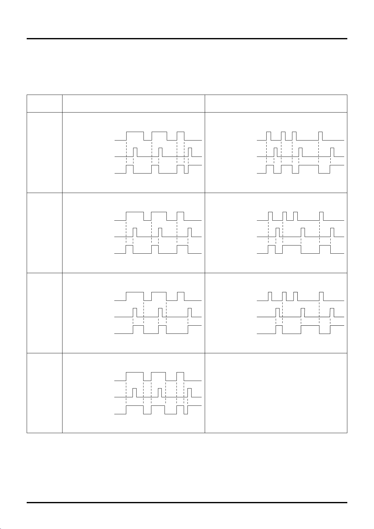
5.1 External Control Operating Mode Selection
There are four modes when operating using signals from external equipment.
1. ON/OFF interlock (the last trigger from either external signal or remote control switch has priority
)
2. ON interlock
3. OFF interlock
4. External priority ON/OFF interlock
Operating Signal
Mode
ON/OFF
inter-
lock
ON
inter-
lock
OFF
inter-
lock
External
priority
ON/OFF
inter-
lock
This mode does not exist.
When external signal is level signal.
When external signal is pulse signal.
(
Optional setting
)
External signal
Remote controller
[ON/OFF] button pressed
Operating
condition
Operating
Stopped
External signal
Remote controller
[ON/OFF] button pressed
Operating
condition
Operating
Stopped
External signal
Remote controller
[ON/OFF] button pressed
Operating
condition
External signal
Remote controller
[ON/OFF] button pressed
Operating
condition
External signal
Remote controller
[ON/OFF] button pressed
Operating
condition
Operating
Stopped
Operating
Stopped
External signal
Remote controller
[ON/OFF] button pressed
Operating
condition
Operating
Stopped
Operating
Stopped
External signal
Remote controller
[ON/OFF] button pressed
Operating
condition
Operating
Stopped
Setting Method
When PZ-41SLB-E is used . . . . . . Set with the remote controller. (Refer to page 67)
When PZ-41SLB-E is Not used . . . Set with the dip switch. (Refer to page 61)
Page 26
23
5.2 Delayed Interlocked Operation
(PZ-41SLB-E, M-NET)
(1) It is possible to delay operation of the Lossnay with respect to the operation of the external device. (Energy saving effect.)
(2) The times that can be set for delayed operation are 10, 20, 30, 40, 50, and 60 minutes.
(3) Delayed operation does not occur if the Lossnay operation was cancelled within the last 2 hours.
(If turned off for a short time, for example during a lunch break, if the direction to restart operation is given within 2 hours, the
Lossnay will restart immediately.)
(4) If an operation button is pressed on the remote controller while the delay timer is operating, the delayed operation is can-
celled and normal operation begins.
Setting Method
When PZ-41SLB-E is used . . . . . . Set with the remote controller. (Refer to page 67)
When PZ-41SLB-E is Not used . . . Set with the dip switch but fixed only for 30 minutes. (Refer to page 60)
5.3 Multiple External device Operation
(PZ-41SLB-E, M-NET)
System Example
When the Operation Signal is a Uncharged a-contact Level Signal
When there are multiple air conditioners or other external devices
Characteristics Ordered parts Notes
Lossnay operates when any of the
external devices operate.
Remote controller • External signals that can be
received are listed below.
Level signal, uncharged a-contact
• If the external device is a pulse signal or charged signal multiple connections can not be made.
Uncharged a-contact Uncharged a-contact
Lossnay
Power supply Power supply Power supply Power supply
Uncharged a-contact
Remote controller
PZ-41SLB-E
* Illustration shows an example when using PZ-41SLB-E.
Air conditioner
remote controller
Air conditioner 1
Air conditioner 2
Air conditioner 4
Air conditioner
remote controller
Air conditioner
remote controller
(Signal cable for space
between Lossnay and
remote controller is less
than 500 m.)
PVC cable φ 0.65 to 1.2
or strand wire 0.3 mm
2
to 1.25 mm2.
Page 27
24
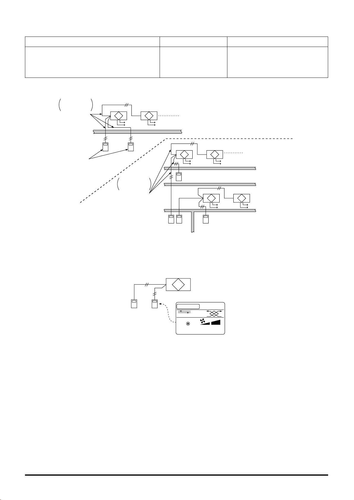
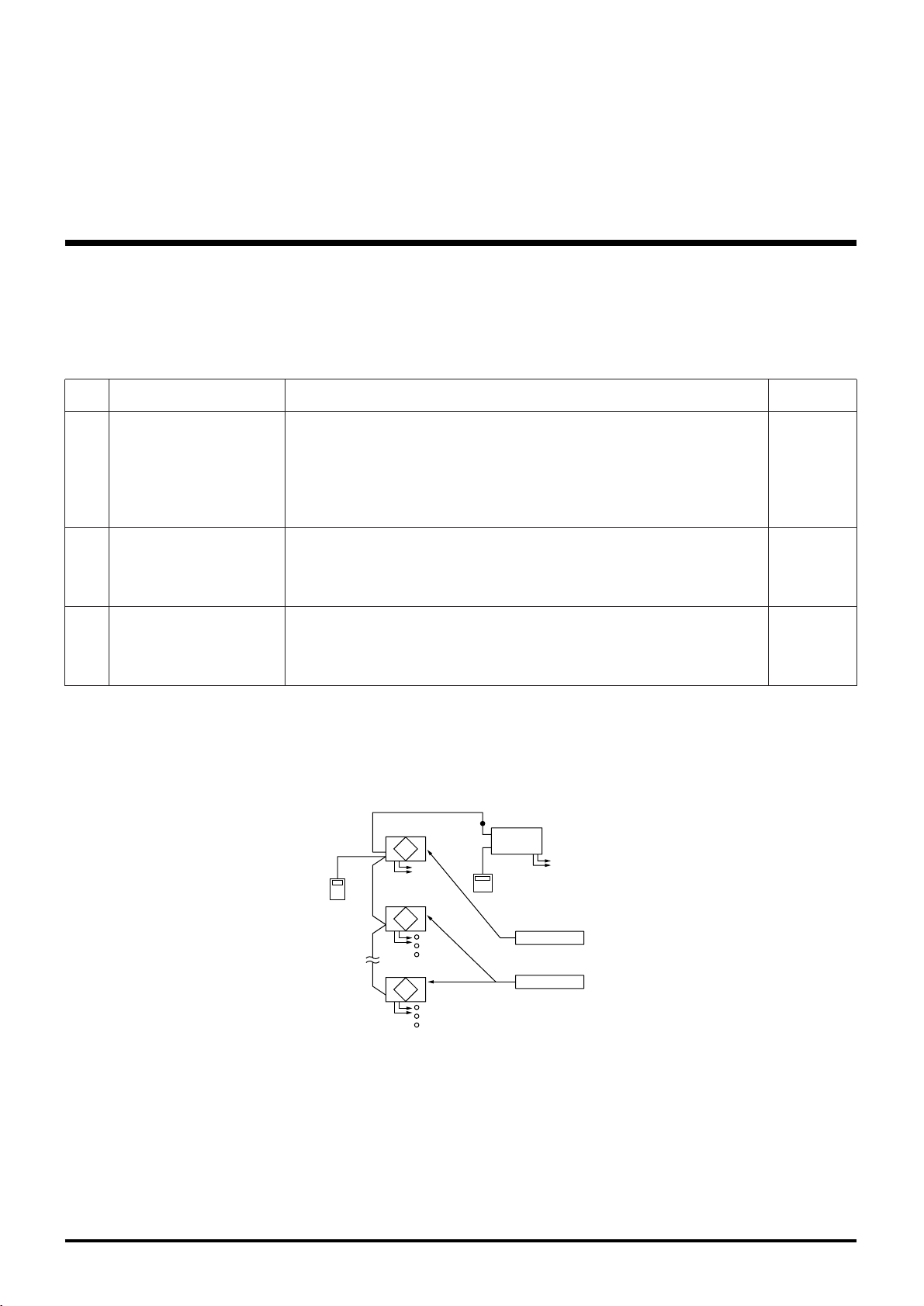
5.4 Multiple Lossnay Units in Interlocked Operation with One Indoor Unit. (M-NET only)
[
Example: System 1
]
Set the Main/Sub switch of the Lossnay connected to the M-NET transmission cable to “Main,” set the second and following
Lossnay units to “Sub,” and connect 5 and 6 of the Lossnay remote controller’s (PZ-41SLB-E) transmission cable terminal
(TM2) to the corresponding point on the next unit.
(
One Point Advice
)
Register the first Lossnay unit and the indoor unit to be interlocked.
It is not necessary to set the address or direct control for the second or following Lossnay units.
Malfunctions of the Lossnay units after the second unit will not appear on the remote controller.
[
Example: System 2
]
Use the Lossnay remote controller to set the air conditioners and Lossnay units to separate groups. Both interlocked operation
of an air conditioner and Lossnay units can be performed independently by connecting the remote display output for the indoor
unit and the external control input for the Lossnay unit.
(
One Point Advice
)
Do not register the indoor unit and Lossnay unit to be interlocked. In addition, ventilation switch on the MA remote controller will
be invalid, and the Lossnays’ error indicator will appear only on the Lossnay remote controller.
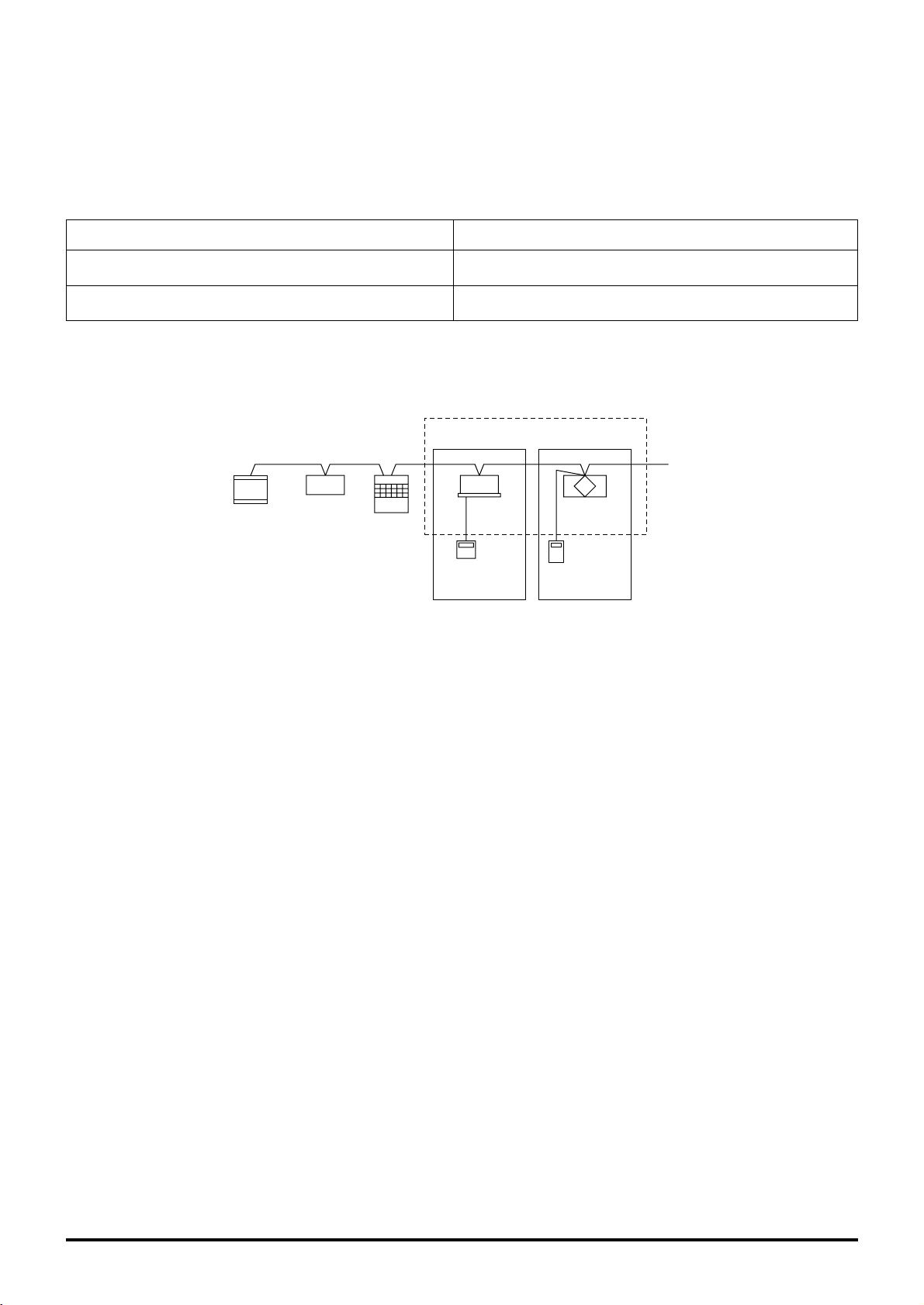
5.5
Interlocked Operation of Equipment such as the
Electrically Operated Damper and Booster Fan.
(M-NET only)
[
Example: System 3
]
Indoor unit
M-NET transmission cable
MA remote
controller
Lossnay
(Main)
Lossnay
(Sub)
Lossnay
(Sub)
TM2 TM2 TM2
Lossnay remote controller
(PZ-52SF-E)
Indoor unit
M-NET
transmission cable
Remote display output
External control input
MA remote
controller
Lossnay Lossnay Lossnay
Lossnay
M-NET transmission cable
Indoor unit
MA remote
controller
Operation moniter output
Electrically operated damper
Booster fan
Page 28

25
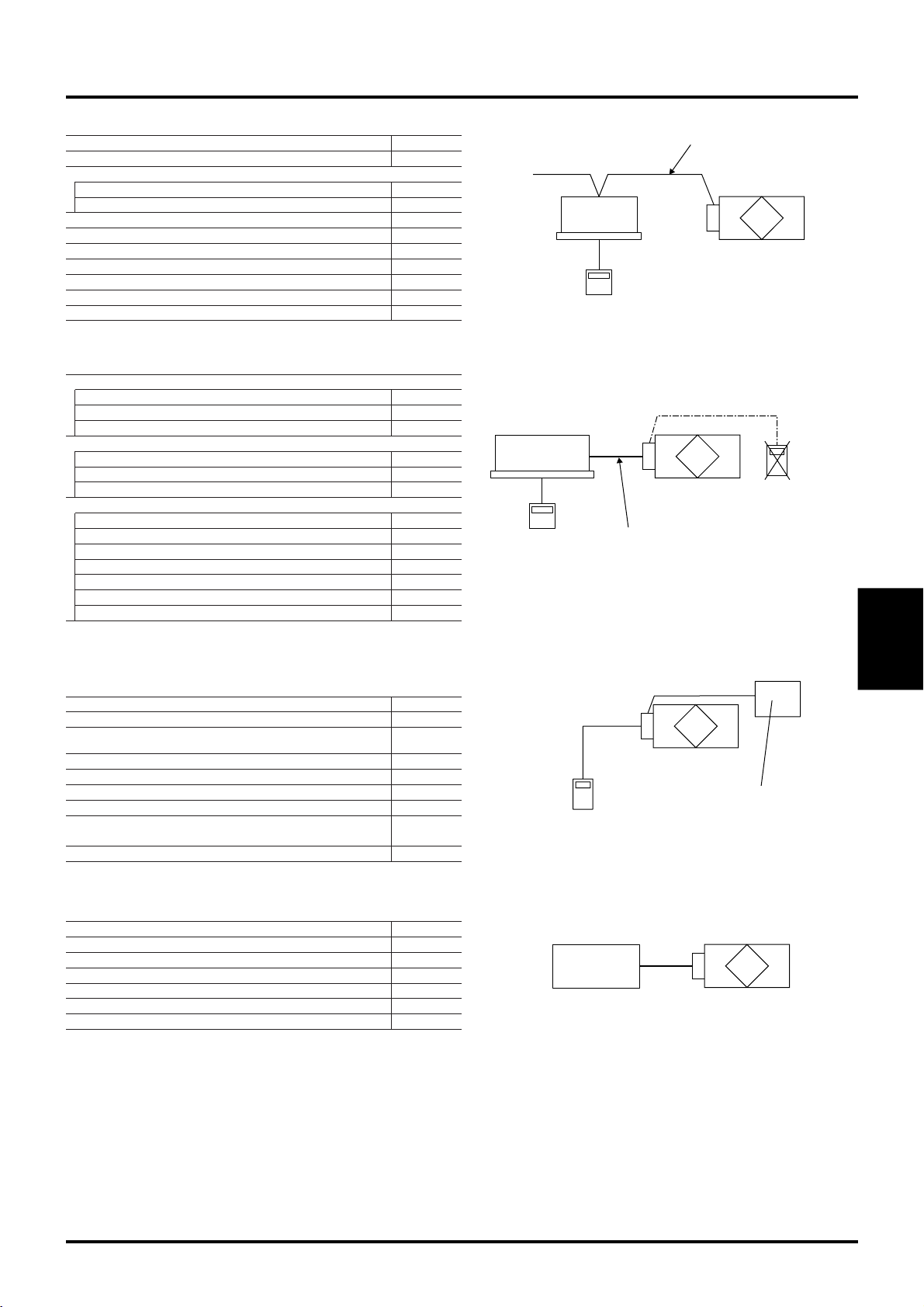
5.7 Connection Method (PZ-41SLB-E, M-NET)
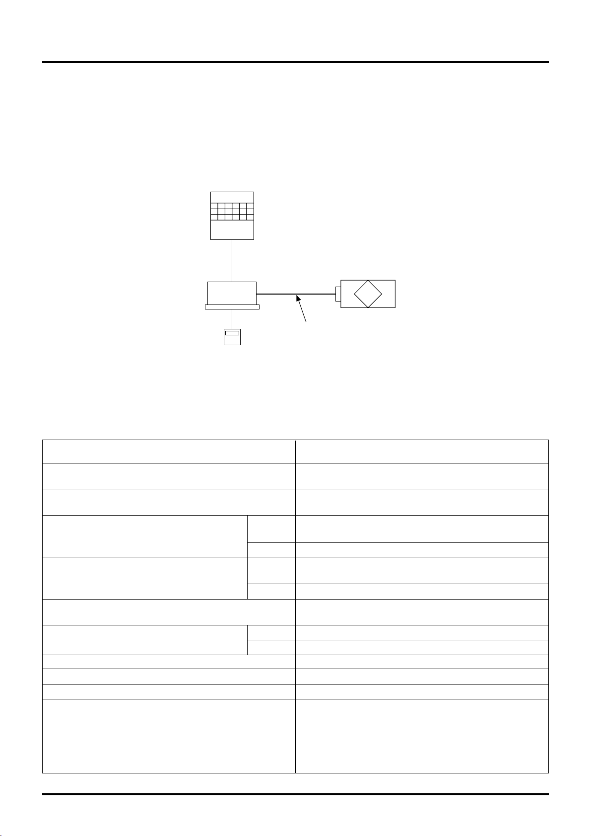
5.6
To Pick Up an Error Signal Externally (PZ-41SLB-E, M-NET)
[
Example System
]
1. Using a Mr. Slim (Acontrol or K-control) indoor unit
Lossnay
M-NET transmission cable
Indoor unit
MA remote
controller
Lamp on monitoring unit
Operation moniter output
TM2
Example:
Mitsubishi Mr.Slim indoor unit
CN2L
Example:
Slim-Lossnay connection cable (Lossnay’s enclosed accessory
)
Lossnay External
control input
If other models are used,
refer to the operating manual
for those models.
500 m
0.5mm2 to 1mm2 sheathed
PVC cable
No more than
1
2
3
Lossnay External
control input
Overall extension length of connection
(
Follow the guidance provided in the operator’s manual.
)
[
When voltage pulse signal (12V DC or 24V DC) is used
]
Connect the signal output
to between TM2 1 and 2.
(
Non-polar
)
External device
1
2
3
TM2
0.5mm2 to 1mm2 sheathed
PVC cable
TM2
Lossnay External
control input
External device
0.5mm2 to 1mm2 sheathed
PVC cable
No more than
500 m
1
2
3
If an optocoupler or any other type
of polar coupler is used at the
uncharged a-contact, connect the
+ to 3 and the - to 1.
2. Using a 12V DC or
24V DC voltage signal
3. Uncharged a-contact
External
device
Power
External device
operation switch
External
device
Power
External device
operation switch
External
device
Power
External device
operation switch
External
device
Power
External device
operation switch
1
2
3
Components for
taking remote output
500 m or less
External control
input (TM2)
Lossnay
4.
Many uncharged acontacts.
Connect 1 and 3 of the external control input terminal (TM2)
through the component for taking remote output at the
uncharged a-contact.
Note:
● If an optocoupler or any other
type of polar contact is used
at the uncharged a-contact,
connect the + to 3 and the
- to 1.
Page 29

26
Maximum 200 milliseconds
5. Connecting to equipment such as an electrically operated damper and picking up the
operating signals.
Connect the power supply cable from the electrically operated damper to 9 and 0 of the operation monitor output ter-
minal (TM3).
Note
:
● The response time to an external control input signal is
shown in the table below.
6. Picking up an error signal.
Lossnay
Operation
monitor output
(
TM3
)
Max. 240V AC 2A
24V DC 2A
Min. 220V AC 100mA
5V DC 100mA
Power supply
Lamp
Electrically operated damper
9
10
Connect to 7 and 8 of Malfunction monitor output terminal
(
TM3
)
Lossnay
Malfunction
monitor output
(
TM3
)
Power supply
Lamp or control equipment
7
8
Max. 240V AC 1A
24V DC 1A
Min. 220V AC 100mA
5V DC 100mA
External Signal Type Response Type
Level signal Maximum 7 seconds
Pulse signal
5.8 High/Low Change Input (PZ-41SLB-E, M-NET)
The fan speed of the Lossnay can be changed externally by using a commercially available CO
2 sensor, etc. The separately
sold remote ON/OFF adaptor (PAC-SE55RA-E) is necessary for connection.
Connection Method
CO2 sensor, etc.
(when CO
2
increases: close)
Remote
ON/OFF adaptor
(PAC-SE55RA-E)
(sold separately)
Lossnay control
board
Switch1
Orange 1
Red 2
Brown 3
High/Low
change
CN16
Securely break off
so as not to use
Wiring length maximum 10 m
Switch 1: High operation switch
(when closed: High operation)
CO2 sensor, etc.
(when CO
2
increases: close)
Remote
ON/OFF adaptor
(PAC-SE55RA-E)
(sold separately)
Lossnay control
board
Switch1
Orange 1
Red 2
Brown 3
High/Low
change
CN16
Securely break off
so as not to use
Wiring length maximum 10 m
Switch 1: Low operation switch
(when closed: Low operation)
When switch 1 is ON, the Lossnay operates at the "High"
fan speed regardless of the remote controller setting.
If you usually ventilate at "Low" fan speed operation, switch
to "High" fan speed operation when the external sensor
shows the air quality going down.
When switch 1 is ON, the Lossnay operates at the "Low" fan
speed regardless of the remote controller setting.
If you usually ventilate at "High" fan speed operation, switch
to "Low" fan speed operation when the external sensor
shows few impurities in the air.
● Externally Directed “High” fan speed Operation
● Externally Directed “Low” fan speed Operation
Page 30

27
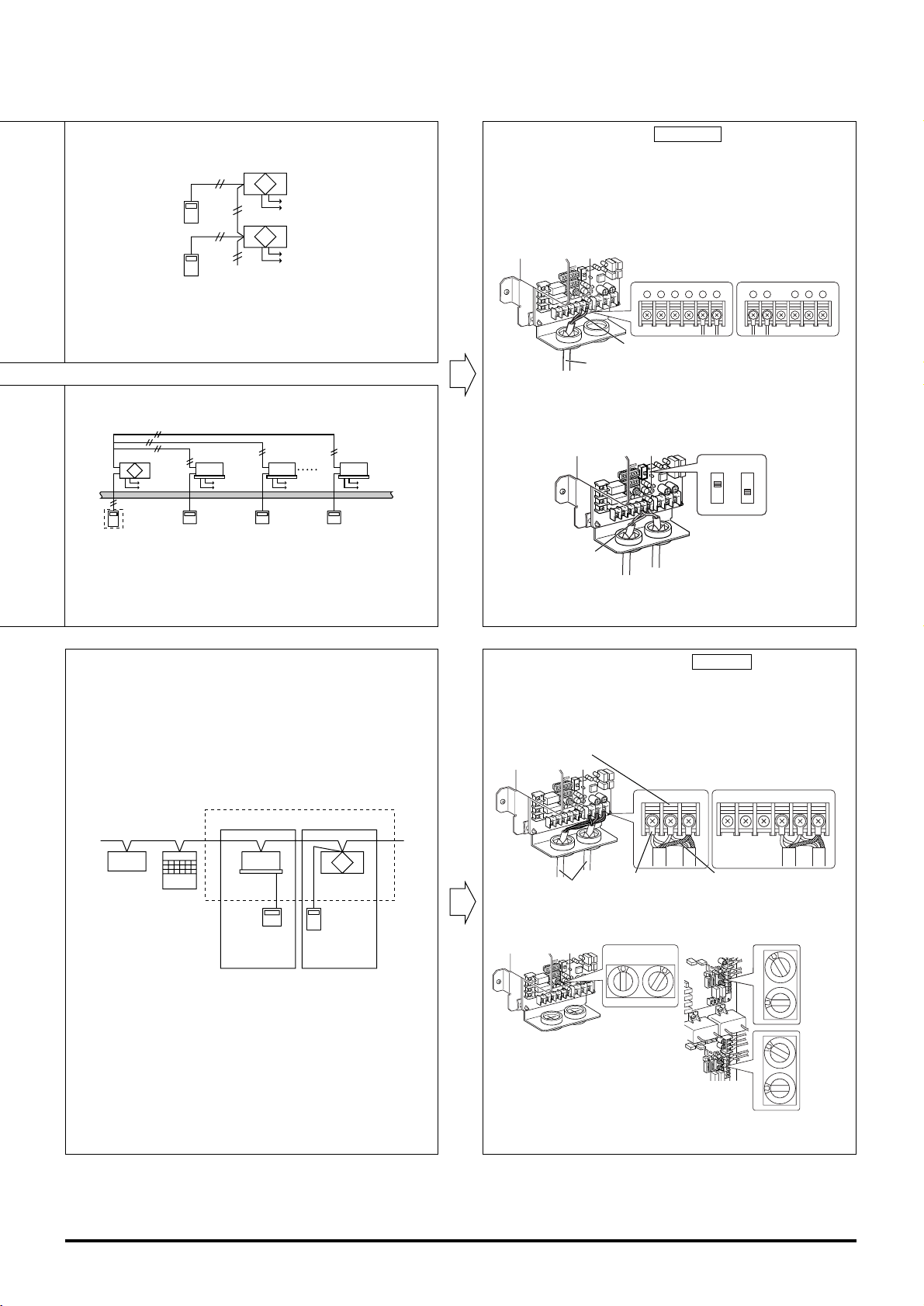
2 When using M-NET for a group of multiple units
● For multiple groups, connect the sensor to each Lossnay.
● Even if the units are in the same group, you can only change Lossnay units connected to the sensor between High/Low
operation.
5.9 Remote/Local control Change and ON/OFF
Input (M-NET only)
The separately sold remote ON/OFF adaptor (PAC-SE55RA-E) is necessary for connection. Remote/Local changing is impossible when using PZ-41SLB-E.
● Insert the separately sold remote ON/OFF adaptor (PAC-SE55RA-E) into CN32 on the Lossnay control table
Note:
● External control input and Remote/Local changing can not be used at the same time.
Lossnay Lossnay Lossnay
PZ-52SF-E
CO2 sensor CO2 sensor CO2 sensor
Group
Remote ON/OFF
adaptor
(PAC-SE55RA-E)
Lossnay control
table
Orange 1
Red 2
Brown 3
CN32
Wiring length maximum 10 m
Switch1
Switch2
X
Y
X
Y
Remote control
circuit Relay circuit
Relay power
Switch 1 : When on, can not use the local remote controller
(PZ-52SF-E) to turn ON/OFF.
* When using PZ-41SLB-E, Remote/Local changing
is impossible.
Switch 2 : When Switch 1 is ON, you can turn Switch 2 ON to
operate the Lossnay, or turn Switch 2 to OFF to turn
off the Lossnay.
Switch 1 : Remote/Local change switch
Switch 2 : ON/OFF switch
X, Y : Relay (Contact rating DC 1 mA)
1 When using PZ-41SLB-E to connect multiple units
● Connect the sensor to the Lossnay with the “Main” setting.
● It is not necessary to connect to any Lossnay with the “Sub” setting.
● Connect any sensor, etc., connected to external change input to the Lossnay with the “Main” setting.
● Any Lossnay with the “Sub” setting will operate at the same High/Low setting as the Lossnay with the “Main” setting when
there is sensor signal input.
Lossna
(Main)
Lossnay
(Sub)
Lossnay
(Sub)
PZ-41SLB-E
Main Sub Sub
CO2 sensor
Note:
● When using the M-NET system, the fan speed being input by this sensor signal will not be displayed on the remote controller.
Page 31

28
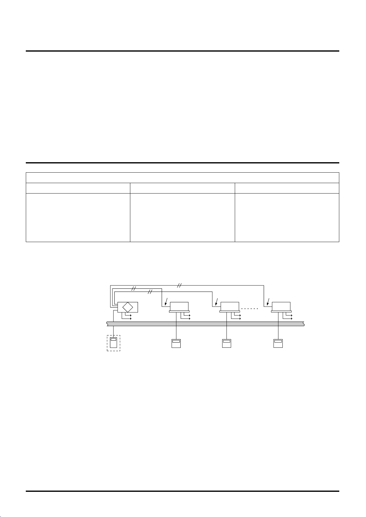
6. Precautions When Designing Systems of M-NET
6.1
Power Supply of the M-NET Transmission Cable
On an M-NET system, the remote controller or central controller operate on power received from the transmission cable. Accordingly, there is need to provide power to the transmission cable.
There are two systems for supplying power. The central system is supplied by a power supply unit. The indoor unit system is
supplied by a outdoor unit. The Lossnay and the Lossnay remote controller can be connected to either system.
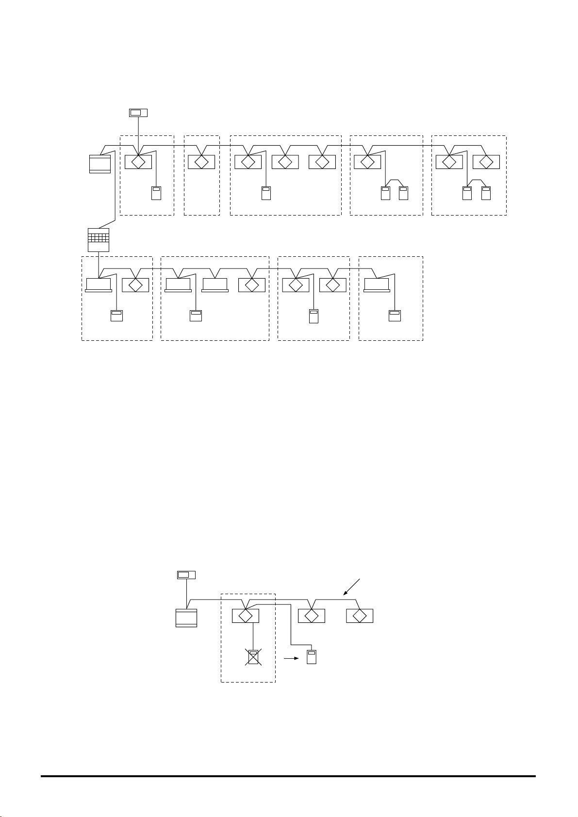
6.2 Restrictions When the Lossnay Units are Con-
nected to the Central Controller M-NET Transmission Cable.
Due to the limited capacity of the power supply unit, the number of Lossnay remote controllers is restricted when the Lossnay MNET remote controllers and Lossnay units are connected to the central controller transmission cable.
This does not apply to Lossnay units that do not receive power from the central controller transmission cable.
The central system The indoor unit system
Central controller
transmission cable
Indoor unit transmission cable
Power supply unit
Outdoor unit
Indoor unit
Lossnay
Lossnay
TB7 TB3
MA remote controller
Lossnay
remote controller
(PZ-52SF-E)
Centralised controller
Transmission cable
Power supply unit
(PAC-SC34KUA)
Lossnay M-NET remote controller
(PZ-52SF-E)
Lossnay M-NET remote controller
(PZ-52SF-E)
Lossnay Lossnay Lossnay Lossnay
Centralised controller
Number of centralised controllers
Non 1 unit 2 units 3 units 4 units
Number of Lossnay
M-NET remote
controllers that can
be connected.
Max. 30 units
Power supply unit
PAC-SC34KUA
Max. 26 units Max. 22 units Max. 18 units Max. 14 units
Max. 50 units
Transmission Booster
PAC-SF46EPA
Max. 46 units Max. 42 units Max. 38 units Max. 34 units
• In the case that a greater number of Lossnay remote controllers than that shown above is connected due to the use of a
power supply unit (PAC-SC34KUA), a transmission booster (PAC-SF46EPA) becomes necessary.
• Transmission Booster (PAC-SF46EPA) can be used without a power supply unit (PAC-SC34KUA) if TB2 (OUTDOOR UNIT
SIDE) is opened, and the M-NET transmission cable is connected to TB3 (ADDITIONAL INDOOR UNIT SIDE).
Page 32

29
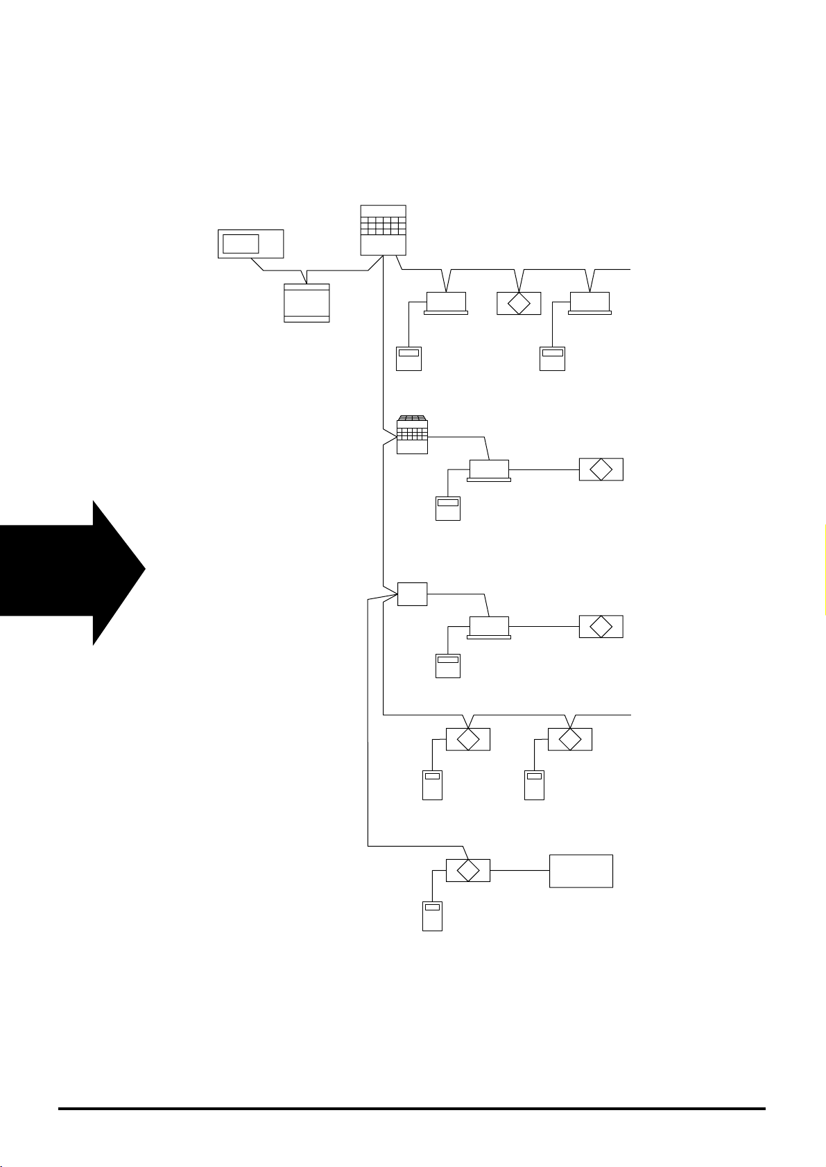
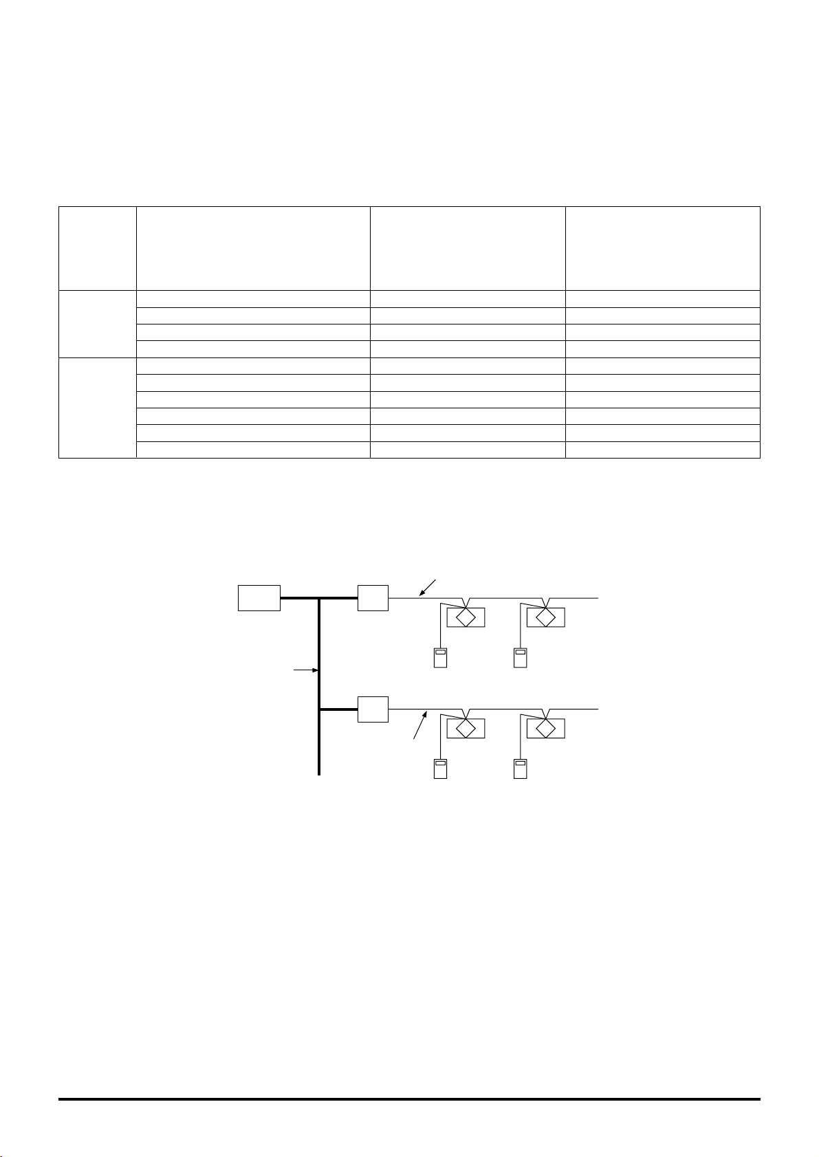
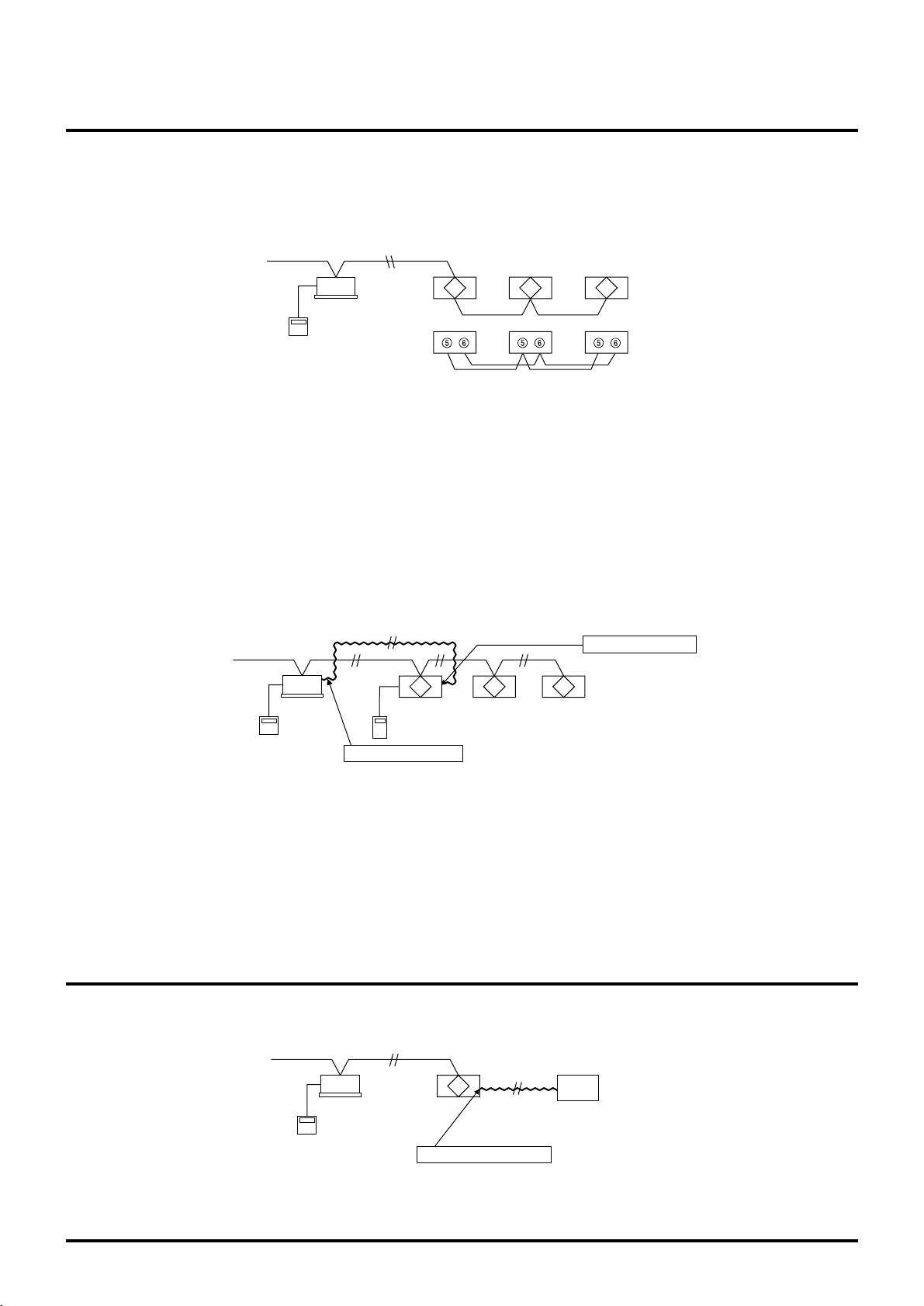
6.3 Wiring Example
Example
<Centalised controller and Lossnay units>
Note:
● This unit cannot be used to extend the transmission cable.
Power
supply unit
Lossnay
remote
controller
Lossnay unit
Centralised controller
Lossnay
remote
controller
Lossnay unit
Lossnay
remote
controller
Lossnay unit
Lossnay
remote
controller
Lossnay unit
Lossnay
remote
controller
Lossnay unit
Lossnay
remote
controller
Lossnay unit
Transmission
booster
Lossnay
remote
controller
ADDITIONAL
INDOOR UNIT SIDE
OUTDOOR
UNIT SIDE
Lossnay unit
Lossnay
remote
controller
Lossnay unit
Lossnay
remote
controller
Lossnay unit
S
TB2
Ground
Ground
TB3
S
Page 33

30
6.4 Power Supply to the Indoor Unit Transmission
Cable.
In principle, the number of indoor units ME remote controllers and Lossnay M-NET remote controllers that can be connected to
one outdoor unit will depend on the type of outdoor unit. The following are the general guidelines when connecting multiple
indoor units and Lossnay units to an outdoor unit.
Indoor units + Remote controllers (Simple remote controllers)+ Lossnay M-NET remote controllers 35
* MA remote controllers and Lossnay unit’s are Not counted.
Centralised controller
Transmission cable
Power supply unit
Lossnay M-NET
remote controller
(PZ-52SF-E)
ME remote
controller
ME remote
controller
Indoor unit Indoor unit Indoor unit
Outdoor unit
The sum of indoor units and remote controllers should be 35 or less.
Lossnay
Page 34

31
7. Cable Installation of the M-NET
7.1 Precautions When Installing Wiring.
1. When routing transmission cable outside of the unit, position it 5 cm or more away
cable for the power supply so that it will not pick up electrical noise. (Never use multicore cable or place the transmission cable in the same conduit as the power supply
cable.
)
2. Never connect the power cable to the terminal block for the transmission cable. This
erroneous connection will burn out the circuit board.
3. Always use 2-core cable for the transmission cable. Routing this transmission cable
with the transmission cable from another system on the same multi-core cable will
result in erroneous sending and receiving of signals which will cause misoperation.
Outdoor unit
Indoor unit
2-core cable
2-core cable
Multi-core cable
Indoor unit
Lossnay
Indoor unit Indoor unit
Lossnay
Indoor unit Indoor unit
Lossnay
Indoor unit Indoor unit
Lossnay
Outdoor unit
Outdoor unit
Outdoor unit
Lossnay M-NET
remote controller
(PZ-52SF-E)
Lossnay M-NET
remote controller
(PZ-52SF-E)
Air conditioner
remote controller
Air conditioner
remote controller
Air conditioner
remote controller
Air conditioner
remote controller
Lossnay M-NET
remote controller
(PZ-52SF-E)
Lossnay M-NET
remote controller
(PZ-52SF-E)
Page 35

32
7.2 Electrical Wiring
Types of control cables
1. Wiring the M-NET transmission cables
• Types of transmission cables
Design cable in accordance with the following <Table 1>.
• Cross-sectional area
1.25 mm2to 2.00 mm
2
<
Table 1
>
System configuration
Shielded cable, such as CVVS or CPEVS.
All facilities.
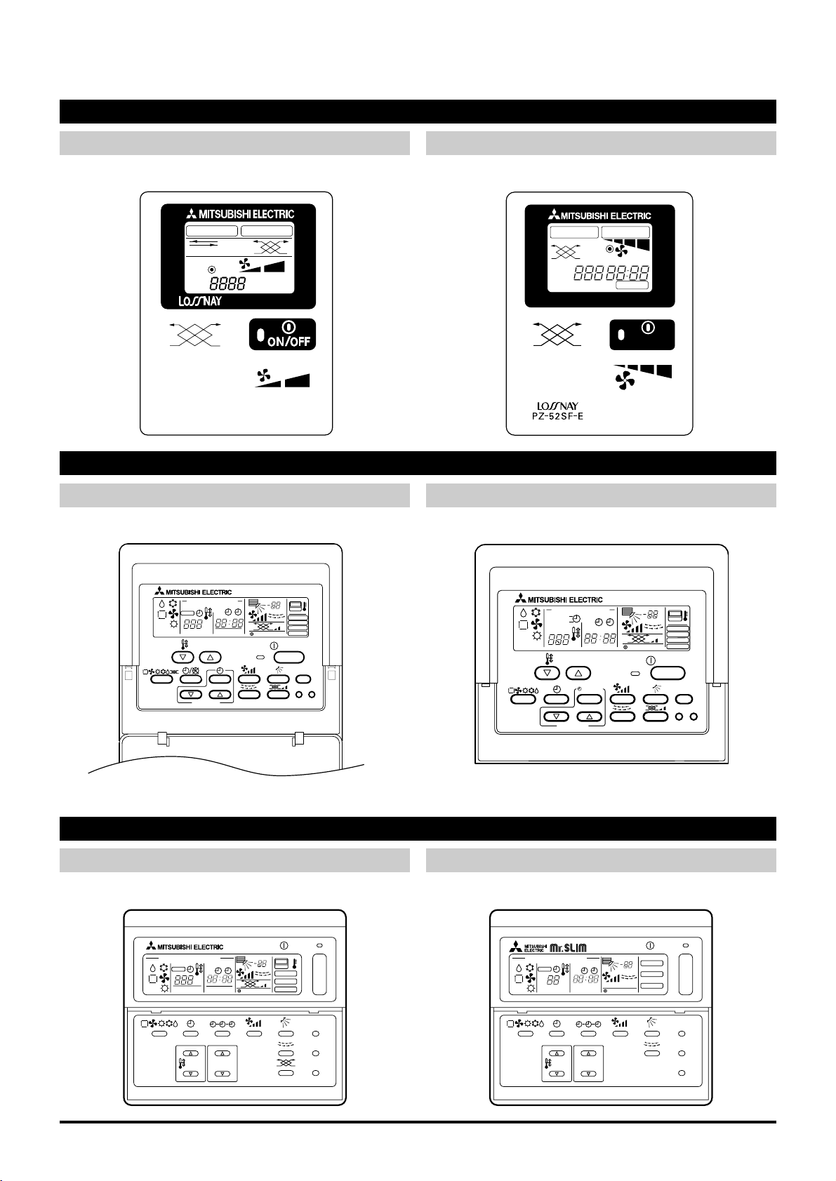
2. Lossnay M-NET remote controller (PZ-52SF-E)
Lossnay M-NET remote controller
Type of cables
Non-shielded cable up to 10 m in length sheathed PVC (2-core)0.75 mm
2
to 1.25 mm2or equiva-
lent. (The same specifications as table 1 for more than 10 m.
)
Length
Add any portion exceeding 10 m up to the longest permissible transmission cable length of 200 m.
(
Shielded sections shall have a cross-sectional area of 1.25 mm
2
to 2.00 mm2.
)
Single-refrigerant system Multi-refrigerant system
Transmission cable length
Type of facility
(Electrical noise potential)
Type of facility
(Electrical noise potential)
Private residence or
facility with no electrical noise.
VCTF, VCTFK, CVV,
CVS, VVR, VVF, or
sheilded cable such as
CVVS or CPEVS
Building free of electrical noise caused by
inverters, electrical
generators and/or highfrequency equipment
(
such as hospitals and
radio stations.
)
Less than 120 m More than 120 m
Regardless of length
Page 36

33
7.3 Length of Control Cable
● Maximum power supply cable length. (L1 + L2, L1 + L3, L1 + L4): The longest length of the cable from the power supply unit
or the indoor unit to the farthest terminal shall be less than 200 m.
● Maximum distance between ends (L2 + L3, L2 + L4, L3 + L4): The length of cable between ends shall be less than 500 m.
● Remote controller cable length (o): The distance between the remote controller and the terminal connected to it shall be 10
m or less.
System Example
When using Lossnay remote controller or ME remote controller.
Lossnay M-NET remote controller
(PZ-52SF-E)
Lossnay M-NET
remote controller
(PZ-525F-E)
Lossnay M-NET
remote controller
(PZ-525F-E)
Lossnay
Lossnay
Transmission
booster
Power supply unit
Lossnay
Lossnay Lossnay
L2
L1
L3
Ground
Centralised controller
L4
T
B
2
T
B
3
Lossnay M-NET
remote controller
(PZ-52SF-E)
Lossnay M-NET
remote controller
(PZ-52SF-E)
Outdoor unit
Indoor unitLossnay
Lossnay Lossnay Lossnay
L2L1
L3
Air conditioner
remote controller
Ground
Transmission
booster
T
B
2
T
B
3
Please:
● Always install the ground cable for the transmission cables in the following way. Route the central control system through the
power supply unit. Route the indoor unit system through the ground terminal on the outdoor unit.
● If the cable length (o) for the remote controller exceeds 10 m, use 0.75 mm
2
, change the section exceeding 10 m to the cable
having a cross-sectional area of 1.25 mm
2
to 2.0 mm2. Add the exceeding section within the “maximum power supply cable
length” restriction of 200 m and the “maximum distance between ends” restriction of 500 m.
● If the cable exceeds the maximum cable length and overall extended length, voltage will drop and cause malfunctioning.
Page 37

34
8. System Designs of M-NET
8.1 Address Definitions
An address is a unique number used to identify each air conditioner and controller.
Device
Note:
● There is no need to set the address unless the Lossnay is connected to the M-NET transmission cable.
System configuration example
Description Address definition range
Indoor unit
Set to specify in order each refrigerant system.
001 to 050
Lossnay Set to specify in order each refrigerant system.
001 to 050 (Note
)
Outdoor unit
Minimum address of the indoor unit within the same
refrigerant system. (+50
)
051 to 100
Local remote controller (master
)
Minimum address of an indoor unit or a Lossnay unit
within the same group. (+100
)
101 to 150
Local remote controller
(
secondary
)
Minimum address of the indoor unit or a Lossnay unit
inside the same group. (+150
)
151 to 200
Branch controllers Minimum address of an outdoor unit. (+1
)
052 to 100
Central controller
When the K-control unit is in control. (000
)
0, 201 to 250
K-transmission converter
Minimum address of the K-control type indoor unit.
(
+200)This cannot overlap with a system controller.
201 to 250
(
013
)
(
015
)(
016
)
(
010
)
(
014
)
(
005
) (
006
) (
007
)
(
004
)
(
003
)
(
002
)
(
001
)
(
101
)
(
105
)(
106
)(
107
)
(
103
)
(
051
)
(
213
)
Centralised
controller
(
000
)
Power supply unit for
transmission cable
K-transmission
converter
Outdoor unit
Indoor unit Indoor unit
Indoor unit
Indoor unit
Indoor unit
Indoor unit
Indoor unit
Lossnay
Lossnay
LossnayLossnay
( )
address
ME remote controller ME remote controller
Lossnay M-NET
remote controller
(PZ-52SF-E)
Lossnay M-NET
remote controller
(PZ-52SF-E)
Lossnay M-NET
remote controller
(PZ-52SF-E)
K-control remote controllerK-control remote controller
K-control remote controllerK-control remote controller
Mr.Slim A-control
remote controller
M-NET compatile
A-control Mr.Slim
outdoor unit
A-control Mr.Slim
indoor unit
Page 38

35
8.3
Precautions When Performing Interlock Settings
(
when interlocked with City Multi indoor unit
)
8.2
Precautions When Performing Group Settings
(
when not interlocked with City Multi indoor unit
)
Precautions
1
The maximum number of Lossnay units in one group is 16. (Refer to page 15.
)
2
When two remote controllers are used within the same group, set one remote controller as the master (address
101 to 150)and the other as the slave (address 151 to 200). (Refer to page 14.
)
3
Group settings:
1
Perform group settings at the centralised controller MJ-103MTRA when being used. If 2 or more centralised conntrollers are being used in combination, perform the group settings at the host one. (Refer to page 76.
)
2 If a centralised controller is not being used, use the Lossnay remote controller to perform the settings. (Refer
to page 72.
)
4
Do not set air conditioners and Lossnay units in the same group. If these units are set to the same group, the
indoor unit or Lossnay will not operate.
5
Turn on the power source for the Lossnay when performing group settings.
6
If the group settings are performed by MELANS, be sure to also set the address for the Lossnay remote controllers to the
group setting. If the remote controller address is not registered, “H0” remains displayed and the system does not start up.
7
No more than three Lossnay remote controllers can be set to the same group in a system using a central controller.
Precautions
1
The maximum number of indoor units that can be interlocked is 16. (Refer to page 17.
)
2
1 Lossnay can be interlocked with an indoor unit. (Refer to page 17.
)
3
Interlock settings:
1
When a centralised controller (MJ-103 MTRA)is being used: if 2 or more centralised controllers are being
used in combination, perform the group settings at the host one. (Refer to page 76.)
2 When MA or ME remote controllers are being used except above 1: Use the MA or ME remote controller for
the interlock settings. (Inerlock settings cannot be performed with the MJ-180A.
)
(
If 1 or 2 do not apply, interlock settings cannot be made.
)
4
Do not register the Lossnay units in a group to be interlocked.
Lossnay units that have been set to interlocked operation within the same group will not operate.
5
When performing the settings using a MA or ME remote controller, always set for interlocked operation to the
smallest address indoor unit in a group. If the setting is not made in this manner, the message “This function is
not available” will appear when operating the ventilation button and interlocking with the Lossnay unit will not be
possible.
6
Turn on the power source for the Lossnay when performing interlock settings.
Page 39

36
9. Automatic Ventilation Switching
9.1 Effect of Automatic Ventilation Mode
The automatic damper mode automatically provides the correct ventilation for the conditions in the room. It eliminates the need
for troublesome switch operations when setting the Lossnay ventilator to “By-pass” ventilation. The following shows the effect
“By-pass” ventilation will have under various conditions.
1. Reduces cooling load
If the air outside is cooler than the air inside the building during the cooling season (such as early morning or at night), “Bypass” ventilation will draw in the cooler outside air and reduce the cooling load on the system.
2. Cooling using outdoor air
During cooler seasons (such as between spring and summer or between summer and fall), if the people in a room cause the
temperature of the room to rise, “By-pass” ventilation draw in the cool outside air and use it as is to cool the room.
3. Night purge
“By-pass” ventilation can be used to release hot air from inside the building that has accumulated in buildings a business district during the hot summer season.
4. Office equipment room cooling
During cold season, outdoor air can be drawn in and used as is to cool rooms where the temperature has risen due to the
use of office equipment.
(Only when interlocked with City Multi and Mr. Slim indoor unit)
9.2 Switching between Heat Recovery and Bypass in the Automatic Ventilation Mode
Control of the automatic ventilation mode is performed according to the table below and automatic algorithm temperature maps.
Note that operation is fixed at heat recovery when the fan is stopped or when there is an abnormality with the thermistor.
Conditions
Temperature Map
When in automatic ventilation mode when not interlocked with City Multi or
Mr. Slim indoor unit. (Including when interlocked by external control input.
)
According to (a).
When the outside temperature has been 28°C or higher in the last 24 hours. According to (b).
Interlocked with City Multi indoor
unit
Fan mode operation for all interlocked indoor units.
Fixed to Lossnay ventilation.
Interlocked with Mr. Slim indoor
unit
Mr. Slim in fan mode. Fixed to Lossnay ventilation.
Mr. Slim in heating mode. According to (c).
Mr. Slim in ventilation mode. According to (a
) or (d)
.
Conditions other than the above. According to (d).
Heating mode for one or more interlocked indoor units.
According to (c).
Conditions other than the above. According to (d).
When indoor units are stopped and only
Lossnay unit is operated.
Fixed to Lossnay ventilation.
Note:
● There is a maximum delay of 30 seconds during damper switching.
● Even if “By-pass” is selected by the Lossnay remote controller, Lossnay ventilation will be performed if the outdoor tempera-
ture is 8°C or less. This is to prevent condensation.
● When multiple City Multi indoor units are connected in a group, the average set temperature for each indoor unit will be the
target temperature. The set temperature is the target temperature for the Mr. Slim indoor unit.
● In the case of (b)when the indoor unit is stopped for the winter, cooling with outdoor air is performed because equipment in
the room may cause a rise in indoor temperature.
Page 40

37
50
45
40
35
30
25
20
15
10
5
0
5
24°C
10°C
10°C
8°C
(°C)
T
OA
(°C)
T
OA
TOA
(°C)
T
RA TRA
(°C)
T
RA
10 15 20 25 30 35 40 45 50
(°C)
50
(°C)
50
50
45
40
35
30
25
20
15
10
5
0
5 10152025 30354045
50
45
40
35
30
25
20
15
10
5
0
51015202524 30 35 40 45
TOA = TRA
TOA = TRA
4°C
4°C
4°C
TOA = TRA
Free Heating
Free cooling
4°C
4°C
6°C
2°C
Lossnay ventilation
By-pass ventilation
Comfortzone (Maintains the condition
held prior to entering the range.
)
(a)
When there is no target temperature
(c)
When there is a target temperature (Heating
)
(b)
When there is no target temperature and the outside
temperature has been 28°C or higher in the last 24 hours.
Target temperature
4°C
10°C
8°C
(°C)
T
OA
TRA
(°C)
50
50
45
40
35
30
25
20
15
10
5
0
5 10152025 30354045
TOA = TRA
4°C
2°C
(d)
When there is a target temperature (Cooling
)
Or the outside temperature has been 28°C or higher in the last
24 hours when interlocked with Mr.Slim and Mr.Slim in
ventilation mode.
Target temperature
8°C
TOA: Outdoor air temperature
T
RA: Indoor air temperature
The indoor air and outdoor air temperature are detected by the two temperature sensors (thermistors) built into the main Lossnay unit.
10. Cold Weather Area Operation
Specifications
When the OA temperature falls below -10°C during operation, the SA fan will change to intermittent operation, off for 10 minutes,
on for 60 minutes. However, intermittent operation can not take place for 60 minutes after starting operation.
Page 41

38
11. Troubleshooting
11.1 Service Flow
Confirmation items
1 Condition of trouble – remote controller dis-
play, etc.
2 Frequency of trouble – date of start of opera-
tion and occurrence
3 Occurrence timing
4 Existence of drawings, equipment (including
controllers and equipment sold separately),
cables, wiring, and settings.
Applicable models
Lossnay
LGH-15 to 200RX
3
-E
Remote controller
PZ-41SLB-E
PZ-52SF-E
Trouble Mode 1 The system will not start properly.
• Check the initialization checklist from
installation to operation (table 1-1).
• Check the system checklist (table 1-2).
Trouble Mode 2
• The check code display appears on the
remote controller.
• The LED of the Lossnay circuit board is
blinking.
Check with the check code list (table 2).
Trouble Mode 3
The remote controller does not operate or
operates irregularly.
The Lossnay does not operate or operates
irregularly.
Trouble Mode 4
Check with the remote controller checklist
(table 3).
Check with the Lossnay checklist (table 4).
Precautions when diagnosing malfunctions
● When removing a transistor or printed circuit board, make sure the breaker is thrown.
● When removing the circuit board, always hold it at both ends and remove carefully so as not to apply force to the surface
mounted parts.
● When removing the circuit board, be careful of the metal edges on the board.
● When removing or inserting the connectors for the circuit board, hold the entire housing section. Never pull on the lead wires.
● When servicing, be sure to recreate the malfunction 2 to 3 times before starting repairs.
● If a malfunction of the printed circuit board is suspected, check for disconnected wires in the print pattern, burnt parts or dis-
coloration.
● If the printed circuit board is replaced, make sure that the switch settings on the new board are the same as the old board.
Page 42

39
Unit error
— —
Error item
11.1.1 Error List
—
«
« « «
« «
«
« « «
«
«
«
—
«
—
«
—
«
— — — —
—
—
—
—
« « « «
—
—
« « «
« « «
—
« « ««
—
« « «
—
« « «
«
—
« « «
2 times
3 times
4 times
5 times
—
—
—
—
—
—
—
9 times
—
—
—
—
—
6 times
—
—
8 times
1 - 5
times
LED 6
turn off
—
4000/4116
*1)
3602
5101
5102
0900
6600
6607
6608
6607/6608
6602/6603/
6604
—
6608
• Cancellation
• Cancel damper operation
• Other controls as normal
•
Lossnay ventilation
fixed (for “Auto” modes)
•
Other controls as normal
•
Lossnay ventilation
fixed (for “Auto” modes)
•
Other controls as normal
• Fan: High speed
• Lossnay ventilation fixed
—
—
—
• Cancellation
—
—
• Cancellation
Fan motor
operation
device error
Damper motor
error
OA
temperature
sensor error
RA
temperature
sensor error
Test operation
Dual address
No ACK
No response
Controller
communication
error
Communication
circuit error
Polarity not
set
PZ-41SLB-E
communication error
Classification
Communication error
Measures taken by Loss-
nay
Remote
controller
display
error
code
LED 1
(green)
Display
(No. of
blinks)
LED 2
(red)
Display
(No. of
blinks)
Error
monitor
output
Reset
power
supply
Change
address
Stop
↓
Start
Error
delete
Cancellation measures
*1) “4000” is displayed on PZ-41SLB-E only.
Page 43

40
Do the capacity of the main power supply on/off unit and wiring span meet specification?
Checkpoint
11.2 Items to Check
Trouble Mode 1: The system will not start properly.
Initialization checklist from installation to operation (Table 1-1)
After checking the system, check the points below up to operation.
1
No.
2 Is the specified power supplied to the Lossnay power terminal (TM1)? (refer to page 54)
3 Is the wiring length of the transmission cable within specifications?
When using PZ-41SLB-E: Overall extension within 500 m
When using M-NET: Maximum power supply length within 200 m, maximum distance between ends
within 500 m (refer to page 33)
4 Does the transmission cable meet regulations? (Type, diameter) (refer to page 56)
5 Is the transmission cable wired at least 5 cm away from the power supply cable?
6 Are multiple transmission or signal cables wired to the same power cable duct?
7 Are multiple transmission cables wired with multi core cables?
8 Is the transmission cable connected to the terminal unit?
(PZ-41SLB-E to TM2 5, 6; M-NET to TB5 A, B)
9 Is the transmission cable securely connected to the Lossnay terminal unit? (refer to page 56, 58)
10 When not using M-NET
If using 1 Lossnay unit, is the Main/Sub change switch (SW1) on the Lossnay circuit board set to “Main”?
If using 2 or more Lossnay units, is the Main/Sub switch set to “Main” on only one unit, and the other units are set
to “Sub”? (refer to page 57)
11 When using M-NET
Is the address switch on the Lossnay circuit board (SA1, SA2) set to the correct number? (refer to page 59)
12 When using external control input
Do the specifications of the external signal match specifications of signals that can be input to the Lossnay? (refer to page 56)
13 When the external input signal is a pulse signal
Is the pulse input switch (SW2-2) on the Lossnay circuit board set to ON? (refer to page 57)
14 When the external signal is 12V DC, 24V DC, or Mr. Slim (A-control or K-control) signal
Is it connected to 1, 2 on the Lossnay external control input terminal unit (TM2)?
15 When the external signal is an uncharged a-contact signal
Is it connected to 1, 3 on the Lossnay external control input terminal unit (TM2)?
16 When M-NET is not being used
Is the external input signal connected to the Lossnay set to “Main”?
17 Is the signal cable length within wiring specifications?
12V DC, 24V DC signal: Within limitation of the external device
Uncharged a-contact signal: Within 500 m
Mr. Slim (A-control or K-control) signal: Within 500 m
18 Is the signal cable wired at least 5 cm away from the power supply cable?
19 Is the output capacity of the Lossnay operation monitor/error monitor within specifications?
Operation monitor output: Maximum 240V AC/24V DC 2A, minimum 220V AC/5V DC 100 mA
Error monitor output: Maximum 240V AC/24V DC 1A, minimum 220V AC/5V DC 100 mA
20 Are the power supply cable, transmission cable, signal cable, etc., securely connected to the proper terminals?
21 Are the settings for the Mai/Sub switch, address switch, and function select switch correct?
Page 44

41
« Check the power supply to the
Lossnay.
« Set the Main/Sub (SW1) switch
to “Main.” (refer to page 57)
« Check the length of the trans-
mission cable wiring.
« Connect the transmission cable
to TM2 56. (refer to page 56)
« Change to the PZ-41SLB-E
remote controller.
1
No.
Remote controller
display does not
appear.
« Power is not supplied to the Lossnay, or power
outside specifications is connected.
« When using only 1 Lossnay, the Main/Sub switch
(SW1) on the Lossnay circuit board is set to “Sub.”
« The overall wiring length of the transmission cable
is longer than specifications (longer than 500 m).
« The remote controller is connected to TB5 (M-NET
transmission cable).
« PZ-52SF-E is connected to the Lossnay local
remote controller.
2 Remote controller
does not operate
(Communication error
display)
« When using multiple Lossnay units, the Main/Sub
switch (SW1) on the Lossnay circuit board of the
second or following unit is set to “Main.”
« The overall wiring length of the transmission cable
is longer than specifications (longer than 500 m).
« Multiple transmission cables are wired with multi
core cables.
«
Set the Main/Sub switch (SW1) of
the second and following Lossnay
units to “Sub.”
(refer to page 57)
« Check the length of the trans-
mission cable wiring.
« For the applied transmission
cable, wire the transmission
cables away from the other
transmission cable.
3 Interlocked operation
with external device
does not occur.
« The type of external signal does not match the
connected terminal unit (charged, uncharged, Mr.
Slim signal).
« The type of external signal does not match the
pulse input switch (SW2-2) setting (level signal,
pulse signal).
« The external device signal is not being input.
« The external device and signal cable wiring is
longer than specifications
12V DC, 24V DC: Longer than limitations of
external device
Uncharged a-contact: Longer than 500 m
Mr. Slim signal: Longer than 500 m
« The Delayed Start mode is set at the remote con-
troller (PZ-41SLB-E).
« The ON Interlocked Operation mode or OFF Inter-
locked Operation mode is set at the remote controller (PZ-41SLB-E).
« When using multiple Lossnay units, the external
control input signal is connected to a unit with the
“Sub” setting made.
«
Check the connection to the external control input terminal (TM2) for
the type of external signal.
(refer
to page 56, 57)
«
Check the type of external signal
and the setting of the pulse input
switch (SW2-2). (refer to page 57)
« Check the external device.
« Check the length of the signal
cable wiring.
« Check the Delayed Start mode
setting at the remote controller
(PZ-41SLB-E). (refer to page 64)
« Check the Interlocked Operation
mode setting at the remote controller (PZ-41SLB-E). (refer to
page 64)
« Connect the external control
input signal to the Lossnay unit
set to “Main.”
Symptom Cause Corrective action
System checklist
(1) Use this checklist when using a PZ-41SLB-E or an external device (Table 1-2-1)
Page 45

42
«
Check remote control unit number
limitations when using a power
supply unit (refer to page 28).
« Check the length of the trans-
mission cable wiring.
« Check the Lossnay address, and
set for an address corresponding to interlocked operation.
(refer to “15. Appendix”)
« Check the length of the trans-
mission cable wiring.
«
Change to the PZ-52SF-E remote
controller (PZ-41SLB-E can not
be used with the M-NET).
(2) System checklist when using the M-NET (Table 1-2-2)
1
No.
Does not interlock with
City Multi. (The Lossnay
cannot be operated by
the ventilation switch on
the ME remote controller,
MA remote controller, or
MELANS.)
« The Lossnay is not set for interlocked opera-
tion, or is set for interlocked operation at the
wrong address.
« The length of the M-NET transmission cable
wiring from the outdoor unit or the system’s
overall wiring length is longer than specifications. (Longer than 200 m from the outdoor
unit, longer than 500 m between ends.)
« PZ-41LSB-E is connected to the Lossnay local
remote controller.
2 Cannot operate using the
MELANS or Lossnay
remote controller.
« The address that has been set for the group in
MELANS and the address for the Lossnay are
different.
« The length of the M-NET transmission cable
wiring from the power supply unit or the system’s overall wiring length is longer than specifications. (Longer than 200 m from the power
supply unit, longer than 500 m between ends.)
« PZ-41LSB-E is connected to the Lossnay local
remote controller.
«
Check the registered address in
MELANS. (refer to “15. Appendix”)
« Check the length of the trans-
mission cable wiring.
«
Change to the PZ-52SF-E remote
controller (PZ-41SLB-E can not be
used with a M-NET system).
3 A unit should operate
independently by
MELANS or the Lossnay
remote controller, but it
interlocks with another
City Multi unit.
« It has been set for interlocked operation with
the City Multi unit.
« Cancel the interlocked operation
setting. (refer to “15. Appendix”)
4 Cannot perform group
settings for the Lossnay
using MELANS, ME
remote controller, or MA
remote controller. (The
remote controller shows
“88” at the time of registration.)
« Power is not supplied to the Lossnay, or power
outside specifications is connected.
« The M-NET transmission cable is connected to
TM2 56.
« The transmission cable is not properly con-
nected to the MELANS or the City Multi.
«
The length of the transmission cable wiring is longer
than specifications (longer than maximum 200 m from
the power supply unit, longer than 500 m between ends.)
«
Check the power for the Lossnay
and perform the registration again.
(refer to “15. Appendix”)
« Connect the transmission cable
to TB5 A, B. (refer to page 58)
« Check the transmission cable
connection. (refer to page 58)
« Check the length of the trans-
mission cable wiring.
5 When power is supplied
to the system, the Lossnay remote controller
continues to display “HO”
and does not start.
(Group registration information disappears.)
« The Group setting was made on a Lossnay
remote controller in a system connected to a
centralised controller MELANS.
« The length of the transmission cable wiring is
longer than specifications (longer than maximum 200 m from the power supply unit, longer
than 500 m between ends.)
«
In a system connected to MELANS,
make the group setting with the
MELANS (Do not make the group setting with the Lossnay remote controller).
(refer to “15. Appendix” or page 72)
« Check the length of the trans-
mission cable wiring.
6 When power is supplied
to the system, the
remote control display
goes blank and the system does not start.
« Over the number of units that can be controlled
with the Lossnay remote controller.
« The length of the transmission cable wiring is
longer than specifications (longer than maximum 200 m from the power supply unit, longer
than 500 m between ends.)
Symptom Cause Corrective action
Page 46

43
« Check the power to the Lossnay.
« Check the Lossnay remote con-
troller address registration with
the MELANS (“HO displays for 3
– 10 minute when electricity is
supplied to the system). (refer to
“15. Appendix”)
« Connect the transmission cable
to TB5 A, B. (refer to page 58)
« Check the Lossnay registration
with the Lossnay remote controller. (refer to “15. Appendix”)
7
No.
The power display “”
does not display when
power is supplied to the
system.
1 When using City Multi and Lossnay interlocked
system (connected to the indoor unit system)
« The transmission cable is not correctly con-
nected to the Lossnay remote controller.
« The power is not turned on for the outdoor unit.
« The length of wiring for the outdoor unit’s M-
NET transmission cable is longer than specification (longer than 200 m).
« Check the transmission cable
connection. (refer to page 70)
«
Check the power to the outdoor unit.
« Check the length of the trans-
mission cable wiring.
8 The “HO” on the remote
controller continues to
flash when the power is
supplied to the system.
« Lossnay is Not supplied with specified power.
« The address for the Lossnay remote controller
does not have a group setting at the MELANS.
« The M-NET transmission cable is connected to
TM2 56.
«
For a Lossnay individual system with no
MELANS,
Lossnay registration has not been
performed by the Lossnay remote controller.
9 “LC 6608” displays on
the remote controller and
the Lossnay does not
operate.
« The remote controller is PZ-41LSB-E and con-
nected to the TB5 A, B.
« Change to the PZ-52SF-E
remote controller (PZ-41SLB-E
can not be used with a M-NET
system).
10 The operation specified
by the centralised controller differs from the
operation of the Lossnay.
« The remote controller is PZ-41SLB-E and con-
nected to the TM2 5-6.
« Change to the PZ-52SF-E
remote controller (PZ-41SLB-E
can not be used with a M-NET
system).
2 When using a Lossnay individual system or
City Multi and Lossnay interlocked system connected to the central system.
« The power supply unit is not connected to the
transmission cable.
« The power to the power supply unit is not
turned on.
« The length of wiring of the M-NET transmission
cable from the power supply unit is longer than
specification (longer than 200 m).
« Connect to the power supply
unit. (refer to page 59)
« Check the power to the power
supply unit.
« Check the length of the trans-
mission cable wiring.
Symptom Cause Corrective action
Trouble Mode 2
● An error code displays on the remote controller.
● Lossnay circuit board LED is flashing or lit up.
An error code displayed on the remote controller (PZ-41SLB-E, PZ-52SF-E) or the M-NET controller and blinking or illumination
of LED1 (green) or LED2 (red) on the circuit board shows the type of error. The LED blink interval is 0.25 seconds for both on
and off. The display duration is approximately 5 seconds.
Error display example: Fan motor operation device error
0.25S 0.25S 0.25S
5S
OFF
ON
Page 47

44
(1) Checklist of error codes displayed on the PZ-41SLB and LED displays
LC 6608
Error code
—
LED1
(green)
—
LED 2
(red)
Lossnay
communication
error
«
When using multiple Lossnay units, the
main/sub setting has not been made
for the second unit and following units.
« Multiple transmission cables have
been wired using multi core wires.
« Transmission cable and power cable
are too close.
« Transmission cable is not securely
connected.
« The length of wiring of the transmis-
sion cable is longer than specification (longer than 500 m).
«
Turn off the main power supply and set the
Main/Sub switch (SW1) (first unit to main, second and following units to sub). (refer to page 57)
« Wire the transmission cable away
from the other transmission cable.
«
Wire the transmission cable at least 5
cm away from the power supply cable.
« Check the transmission cable con-
nection. (refer to page 56)
« Check the length of the transmission
cable wiring.
RC6608
SRC 6608
— —
Communication error
between
remote controllers
(when 2
remote controllers are
connected)
« Multiple transmission cables have
been wired using multi core wires.
« Transmission cable and power sup-
ply cable are too close.
« Transmission cable is not securely
connected.
« The length of wiring of the transmis-
sion cable is longer than specification (longer than 500 m).
« Wire the transmission cable away
from the other transmission cable.
«
Wire the transmission cable at least 5
cm away from the power supply cable.
« Check the transmission cable con-
nection. (refer to page 67)
« Check the length of the transmission
cable wiring.
LC 0900
SLC 0900
— — Lossnay
trial operation
« Trial operation switch on the Loss-
nay circuit board (SW 2-1 or SW 2-
3) is set to ON board.
« Check the test operation switch.
(refer to page 62)
LC 4000
SLC 4000
2
blinks
—
Fan motor
operation
device error
« Lossnay fan will not stop. « Replace the table.
LC 3602
SLC 3602
3
blinks
— Damper
related
error
« Damper board operation is not cor-
rect.
« Connectors for the damper unit are
not correctly connected.
« Remove the load and check or
move the damper board by hand.
«
Check the connection of the lead wire’s
connectors and the circuit connector.
LC 5101
SLC 5101
4
blinks
—
OA thermistor related
error
« Connectors for the thermistor are
not correctly connected.
« Check the connection of the lead
wires connectors and the circuit
connector.
LC 5102
SLC 5102
5
blinks
—
RA thermistor related
error
« Connectors for the thermistor are
not correctly connected.
« Check the connection of the lead
wires connectors and the circuit
connector.
——— 9
blinks
— Remote
controller
communication
error
« Multiple transmission cables have
been wired using multi core wires.
« Transmission cable and power sup-
ply cable are too close.
« Transmission cable is not securely
connected.
« The length of wiring of the transmis-
sion cable is longer than specification (longer than 500 m).
« Wire the transmission cable away
from the other transmission cable.
«
Wire the transmission cable at least 5
cm away from the power supply cable.
« Check the transmission cable con-
nection. (refer to page 56, 57)
« Check the length of the transmission
cable wiring.
“Filter” blink-
ing
— —
Warning to clean air
filter by comulative
operation time
« Interval for cleaning Lossnay air fil-
ter has elapsed.
« After cleaning the air filter press the
“Filter” button on the remote controller 2 times.
“HO” blinking blink-
ing
— System is
starting
«
LED1 blinks at 1 second intervals during
starting operation (maximum of 45 seconds.)
« There is no error.
Symptom Cause Corrective action
*1 LC: Lossnay set to Main SLC: Lossnay set to Sub RC, SRC: remote controller (PZ-41SLB-E)
*2 Because the LGH-150/200RX
3-E is loaded with 2 control circuit units, “SLC” may display even with only 1 Lossnay.
When “SLC” displays, check and perform maintenance on the upper side circuit.
Page 48

45
(2) Checklist of error codes displayed on the PZ-52SF-E, M-NET controllers, and LED dis-
plays (Table 2-2)
6600
Error code
—
LED1
(green)
6
blinks
LED 2
(red)
Multiple
address error
«
There is another unit with the same
address setting.
« Check the addresses of devices in
the system.
6607
6608
— 8
blinks
No ACK error
No answer
error (MNET communication
error)
«
Power supply to Lossnay is not turned on.
« Lossnay address was changed.
« Multiple transmission cables have
been wired using multi core wires.
« Transmission cable is not securely
connected.
«
The length of wiring of the transmission
cable is longer than specifications (longer
than maximum 200 m from the power supply unit, longer than 500 m between ends).
« Check the power to the Lossnay.
« Check the Lossnay address.
« Wire the transmission cable away
from the other transmission cable.
« Check the transmission cable con-
nection. (refer to page 58)
« Check the length of the transmission
cable wiring.
0900 — — Lossnay
trial operation
« Trial operation switch on the Loss-
nay circuit board (SW 2-1 or SW 2-
3) is set to ON.
« Check the trial operation switch.
(refer to page 62)
4116 2
blinks
—
Fan motor
operation
device error
« Lossnay fan will not stop. « Replace the table.
3602 3
blinks
— Damper
related
error
« Damper board operation is not cor-
rect.
« Connectors for the damper unit are
not correctly connected.
« Remove the load and check or
move the damper board by hand.
«
Check the connection of the lead wires
connectors and the circuit connector.
5101 4
blinks
—
OA thermistor related
error
« Connectors for the thermistor are
not correctly connected.
« Check the connection of the lead
wires connectors and the circuit
connector.
5102 5
blinks
—
RA thermistor related
error
« Connectors for the thermistor are
not correctly connected.
« Check the connection of the lead
wires connectors and the circuit
connector.
6602
6603
6604
— 1 - 5
blinks
Communication circuit section error
« Error with transmission cable.
« Controller where error originally
occurred is defective.
« Lossnay board is defective.
« Check transmission cable relations.
« Check the controller where the error
occurred.
« Replace the circuit board.
——— — Lit No M-NET
connection
information
« Lossnay does not have Group set-
ting (registration) made.
«
Check the Lossnay address and confirm that the group setting is made.
(refer to page 72 or “15. Appendix”)
Filter blinking — —
Warning to clean air
filter by comulative
operation time
« Interval for cleaning Lossnay air fil-
ter has elapsed.
« After cleaning the air filter press the
“Filter” button on the remote controller 2 times.
——— Lit — In delayed
start operation
« Delayed start operation is set at the
function select switch (SW 5-1) on
the Lossnay circuit board.
« There is no error.
——— LED6 (red)
off
No power
to M-NET
transmission cable
« Power supply is not supplied to the
M-NET transmission cable.
« Wiring length of the transmission
cable is from the power supply unit
or the outdoor unit is longer than
specification (maximum extension
200 m).
« Check the connection of the power
supply unit, outdoor unit and transmission cable.
« Check the length of the transmission
cable wiring.
Symptom Cause Corrective action
*1 The letters “LC” that display with the error code show a Lossnay unit type, and the number in the third column shows the
address.
*2 Because the LGH-150/200RX
3-E is loaded with 2 control circuit units, 1 Lossnay unit has 2 addresses. Check and perform
maintenance on the table related to the address set at the address switch (SA1, SA2).
Page 49

46
Trouble Mode 3: The remote controller does not operate or operates irregularly.
(1) Checklist for when using the PZ-41SLB-E (Table 3-1)
(2) Checklist for when using PZ-52SF-E (Table 3-2)
1
No.
Nothing displays on the
LCD.
« Transmission cable is connected to the wrong
terminal
« No Lossnay is set to “Main.”
« Power supply to the Lossnay is not turned on.
« Lossnay is connected to a power supply with a
rating outside specification.
« Transmission cable is not securely connected.
«
The length of wiring of the transmission cable is
longer than specification (longer than 500 m).
«
Check the transmission cable
connection (connected to 56
of terminal unit TM2 on the Lossnay board). (refer to page 56)
«
Turn off the main power supply and
set the Main/Sub switch (SW1) (first
unit to main, second and following
units to sub). (refer to page 57)
«
Check the power supply to the Lossnay.
« Check the power supply.
« Check the transmission cable
connection. (refer to page 56)
« Check the length of the trans-
mission cable wiring.
2 Starts or stops, or the
display changes, by
itself.
« Multiple transmission cables have been wired
using multi core wires.
« Transmission cable and power supply cable
are too close.
«
Wire the transmission cable away from
the other transmission cable.
«
Wire the transmission cable at least 5
cm away from the power supply cable.
3 Displays a error code
that is not in the check
list.
« Letters on the remote controller LCD are dim.
« The release of the Delay Start button or the Fil-
ter Reset button is not good.
« Replace the remote control.
« Replace the remote control.
4 Cannot stop the Lossnay
with the remote controller
(display shows “Interlocked”).
« External priority ON/OFF setting is made. « Check the interlocked operation
mode setting. (refer to page 64)
5 Cannot switch fan speed
with the remote controller.
« High/Low change input (CN16) is ON.
«
The function select switch (SW2-4.5) on the Lossnay circuit has the fixed high or fixed low speed set.
« Check the High/Low change
input (CN16). (refer to page 58)
« Check the function select switch
(SW 2-4.5) (refer to page 60)
6 Lossnay operates when
the main power supply
turns on and the remote
controller displays.
« Main power supply was cut during Lossnay
operation.
« Stop the Lossnay with the
remote controller, then wait at
least 10 second and turn off the
main power supply .
Symptom Cause Corrective action
1
No.
Nothing displays on the
LCD.
« Transmission cable is connected to the wrong
terminal
« There is no power supply unit (for Lossnay only
systems).
« The power supply unit is not turned on.
« Transmission cable is not securely connected.
« Wiring length of the transmission cable is from
the power supply unit or the outdoor unit is
longer than specifications (maximum extension
200 m).
« Check the transmission cable
connection (connected to A, B
of terminal unit TB5 on the Lossnay board). (refer to page 58)
« Install the power supply unit.
« Check the power to the power
supply unit.
« Check the transmission cable
connection. (refer to page 58)
« Check the length of the trans-
mission cable wiring.
Symptom Cause Corrective action
Page 50

47
« After supplying power to the sys-
tem, HO blinks for a maximum of
about 10 minutes.
(This is not an error.)
«
Make the group setting (registration). If using a system with a centralised controller, register at the
centralised controller. If there is
only the Lossnay remote controller,
register at the remote controller.
(refer to “15. Appendix” or page 72)
«
Check the group setting at the
MELANS. (refer to “15. Appendix”)
« Check the power supply to the
Lossnay.
(refer to page 54)
« Check the power supply.
« Check the transmission cable
connection (connected to A, B
of terminal unit TB5 on the Lossnay board).
(refer to page 58)
« Check the Lossnay address.
(refer to page 59)
« If the board has been replaced,
reset the group settings. (refer to
“15. Appendix”)
« Check the length of the trans-
mission cable wiring.
2
No.
Displays “HO” and does
not start.
« It is less than 10 minutes since the power was
supplied to the system.
« Group setting (registration) has not been
made.
«
Remote control address has not been registered
in the group setting by the
centralised controller.
« Power supply to the Lossnay is not turned on.
« Lossnay is connected to a power supply with a
rating outside specification.
« Lossnay transmission cable connection termi-
nal is wrong.
« Lossnay address was changed.
« Lossnay board was changed.
«
The length of wiring of the transmission cable is longer
than specifications (longer than maximum 200 m from
the power supply unit, longer than 500 m between ends).
3 Cannot register the Loss-
nay from the remote controller or the controller.
« Power supply to the Lossnay is not turned on.
« Lossnay is connected to a power supply with a
rating outside specification.
« Transmission cable to the Lossnay is not con-
nected.
« Lossnay transmission cable connection termi-
nal is wrong.
« Lossnay address is wrong.
«
The length of wiring of the transmission cable is longer
than specifications (longer than maximum 200 m from
the power supply unit, longer than 500 m between ends).
« Check the power supply to the
Lossnay.
(refer to page 54)
« Check the power supply.
« Check the transmission cable
connection.
(refer to page 58)
« Check the transmission cable
connection (connected to A, B
of terminal unit TB5 on the Lossnay table). (refer to page 58)
« Check the Lossnay address.
(refer to page 59)
« Check the length of the trans-
mission cable wiring.
4
Starts or stops, or the display changes, by itself.
« Set for interlocked operation with City Multi. « Cancel interlocked operation
setting. (refer to “15. Appendix” )
5
Displays a error code that
is not in the checklist.
« Letters on the remote controller LCD are dim. « Replace the remote controller.
6
Cannot stop the Lossnay
with the remote controller
(display shows “Central”).
« “Cancel Operation” setting is made from the
MELANS.
« External priority ON/OFF setting is made.
« Remote/nearby switch input (CN32) is set to
“Remote.”
« Check the settings of the
MELANS.
« Check the interlocked operation
mode setting. (refer to page 61)
« Check the remote/nearby
change input (CN32).
Symptom Cause Corrective action
Page 51

48
Trouble Mode 4: The Lossnay does not operate or operates irregularly.
Lossnay checklist (Table 4).
1
No.
The fan does not operate.
The fan does not operate
normally.
« Connectors for the fan connection or connec-
tors for the control circuit section connection
are not secure.
« Power supply is not supplied to the Lossnay, or
power outside specifications is connected.
« Lossnay group setting is not made by using the
M-NET. (LED2 lights)
« Check the lead wire connectors
and the control circuit section
connectors.
« Check the power supply. (refer to
page 54)
« Check the Lossnay address and
the group setting (LED2 lights
when not using M-NET. This is
no error.)
3 Fan will not stop. « The trial operation switch (SW 2-1) is ON. « Check the test operation switch
(SW2-1). (refer to page 62)
4 Lossnay operates when
main power is turned on.
« The PZ-41SLB-E is being used.
«
By using the M-NET, the power supply ON/OFF
setting is set to ON at the function select switch
(SW 2-6) on the Lossnay circuit board.
« By using the M-NET, the automatic recovery
following power supply interruption (refer to
page 61) setting is made at the function select
switch (SW 5-4) on the Lossnay circuit board.
«
When the main power supply is
turned off while the Lossnay is
operating from the remote controller, the Lossnay will resume
operation when the main power is
turned back on (this is no error).
«
Check the power supply ON/OFF
setting of the function select
switch (SW2-6). (refer to page 60)
«
Check the automatic recovery following power supply interruption
setting of the function select
switch (SW5-4). (refer to page 61)
2 Interlocked operation
with external device
(air conditioner) does not
occur.
« The type of external signal does not match the
connected terminal unit (charged, uncharged,
Mr. Slim signal).
« The type of external signal does not match the
pulse input switch (SW2-2) setting (level signal,
pulse signal).
« The external device signal is not being input.
« The external device and signal cable wiring is
longer than specifications
(12V DC, 24V DC:
Longer than limitations
of external device
Uncharged a-contact: Longer than 500 m
Mr. Slim signal: Longer than 500 m)
« The Delayed Start mode is set at the remote
controller (PZ-41SLB-E) or the function select
switch (SW 5-1) on the Lossnay circuit board.
« The ON Interlocked Operation mode or OFF
Interlocked Operation mode is set at the
remote controller (PZ-41SLB-E) or the function
select switch (SW 5-7,8) on the Lossnay circuit
board.
« When using multiple Lossnay units, the exter-
nal control input signal is connected to a unit
with the “Sub” setting made.
« In a group of multiple Lossnay units with the M-
NET, the external control input signal is connected to a Lossnay unit other than the one
with the smallest address.
« There is a communication error with the
remote controller or controller.
«
Check the external signal type and the
external control input terminal (TM2)
connection. (refer to page 56, 57)
«
Check the external signal type and
the pulse input switch (SW2-2)
setting. (refer to page 57)
« Check the external device.
« Check the wiring length of the
signal cable.
«
Check the delayed start settings of
the remote controller (PZ41SLB-E)
and the function select switch
(SW5-1). (refer to page 60, 64)
«
Check the interlocked operation mode
settings of the remote controller
(PZ41SLB-E) and the function select
switch (SW5-7, 8). (refer to page 61, 64)
« Connect the external control
input signal to the Lossnay set to
“Main.”
(refer to page 57)
« Connect the external control
input signal to the Lossnay in the
group with the lowest address.
« Check the remote controller or
controller.
Symptom Cause Corrective action
Page 52

49
5
No.
Supply air fan periodically stops operating.
« When the outdoor air temperature is -10°C or
less, operation stops after a fixed period of
about 10 minutes to keep the Lossnay Core
from freezing. (Cold weather area spec)
« When connected to a Mr. Slim or a City Multi
by a duct, operation stops when the air conditioner is defrosting.
« This is no error.
« This is no error.
6 Takes in air from out-
doors during interlocked
operation with a Mr. Slim
or a City Multi, but supply
air fan doesn’t stop operating when defrosting.
« The indoor unit’s outside air intake selection is
invalid.
« Set the outdoor air intake selec-
tion of a indoor unit to “ON.”
7 The supply air fan and
exhaust fan both periodically stop operating.
« When connected to Mr. Slim or City Multi by a
duct and the function select switch (SW 5-3) on
the Lossnay circuit board is ON, operation
stops when the air conditioner is defrosting.
« Check the function select switch
(SW5-3). (refer to page 60)
8 Fan speed will not
change.
« The High/Low switching extermary input
(CN16) is set to ON.
«
The function select switch (SW2-4.5) on the Lossnay circuit board is set to the high fixed or low fixed fan speed.
« The trial operation switch (SW2-1) is turned
ON.
« Check the High/Low change
input (CN16). (refer to page 58)
« Check the function select switch
(SW2-4,5). (refer to page 60)
« Check the trial operation switch
(SW2-1). (refer to page 62)
9 Damper board does not
operate.
« The outside air temperature is less than 8°C.
« The damper board operation is defective.
« The thermistor related connectors are not
securely connected.
« The damper related connectors are not
securely connected.
« The trial operation switch (SW2-1 or SW2-3) is
turned ON.
« When using the remote controller to change
ventilation mode, there may be a delayed start
of up to 30 seconds depending on the timing.
«
Check the outdoor air temperature.
«
Remove the load and check or
move the damper board by hand.
« Check the connections of the
lead wire connectors and the circuit connectors.
« Check the connections of the
lead wire connectors and the
control circuit connectors.
«
Check the trial operation switch (SW21 or SW2-3). (refer to page 62)
« This is no error.
10
Operation monitor output
is late with regard to external control input ON/OFF.
« When using the PZ-41SLB-E there is a maxi-
mum delay of 7 seconds, or without using
there is a maximum delay of 3 seconds.
«
This is
no error.
11 Operation monitor output
is OFF during operation.
« When the function select switch (SW 5-2) on
the Lossnay circuit board is ON, for operation
monitor output for interlocked operation with
the supply air fan, it turns OFF when the outside air is -10°C or less or when the air conditioner is defrosting.
«
Check the function select switch
(SW5-2). (refer to page 60)
12 Delayed start operation
does not work when
Delayed start is set.
« When using the PZ-41SLB-E, the circuit func-
tion select switch is set for delayed start.
«
Set delayed start at the remote controller
(the circuit board switch is not in effect when
using the PZ-41SLB-E). (refer to page 64)
13
Lossnay does not operate when
power is on even when the
power on/off setting is made.
« Using the PZ-41SLB-E. « The power supply ON/OFF set-
ting is not in effect when using
PZ-41SLB-E.
14 Interlocked operation is
different from the settings.
« When using the PZ-41SLB-E, the circuit func-
tion select switch is set for interlocked operation.
«
Set interlocked operation at the
remote controller (the circuit board
switch is not in effect when using the
PZ-41SLB-E). (refer to page 64)
Symptom Cause Corrective action
Page 53

50
Temperaturers vs. thermistor resistance table
Temperature
(°C)
Resistance
value (kΩ)
Temperature
(°C)
Resistance
value (kΩ)
Temperature
(°C)
Resistance
value (kΩ)
Temperature
(°C)
Resistance
value (kΩ)
Temperature
(°C)
Resistance
value (kΩ)
-40 88.85 - ∞ -7 17.92 8 9.57 23 5.38 38 3.17
. . .
. . .
. . .
. . .
-6 17.16 9 9.20 24 5.19 39 3.06
-20 32.43 -5 16.43 10 8.84 25 5.00 40 2.96
-19 30.92 -4 15.74 11 8.49 26 4.82 41 2.86
-18 29.50 -3 15.08 12 8.17 27 4.65 42 2.77
-17 28.14 -2 14.45 13 7.85 28 4.49 43 2.68
-16 26.87 -1 13.86 14 7.55 29 4.33 44 2.59
-15 25.65 0 13.29 15 7.27 30 4.18 45 2.51
-14 24.51 1 12.74 16 6.99 31 4.03 46 2.43
-13 23.42 2 12.22 17 6.73 32 3.89 47 2.35
-12 22.39 3 11.72 18 6.48 33 3.76 48 2.28
-11 21.41 4 11.25 19 6.24 34 3.63 49 2.21
-10 20.48 5 10.80 20 6.01 35 3.51 50 2.14
-9 19.58 6 10.37 21 5.79 36 3.39
-8 18.73 7 9.96 22 5.58 37 3.28 87.5 - 0.72 - 0
Page 54

51
11.3 Circuit Test Point
LED1 (green)
• When blinking, there is an error with the Lossnay unit (number of blinks indicates the type of error).
• Blinks at 1 second intervals when starting.
• Lit during delayed start, normally off at other times.
LED2 (red)
• Blinking indicates M-NET communication error (number of blinks indicated the type of error).
• Lit when not connected to other M-NET units (registered).
Exhaust fan operation unit (combined)
Fuse (6.3 A/250 V)
Supply fan operation unit (combined)
Power supply
220 V to 240 V AC: up to 50 Hz
220 V AC: up to 60 Hz
(60 Hz is not used in EU)
Transformer input
Damper motor
operation unit
220 V - 240 V AC
5 V DC
12 V DC
Transformer output
11 V to 20 V AC
GND
LED4 (red)
• lit when power is
supplied to circuit
12 V DC
Thermistor
(outdoor air)
Thermistor
(return air)
Damper position
detector
• during Lossnay
ventilation: 12 V DC
• during by-pass
ventilation: 0 V
LED6 (red)
• lit when power is
supplied to M-NET
M-NET transmission cable (shielded)
M-NET transmission cable
(PZ-52SF-E, MELANS, power supply unit or
City Multi)
Not in use
For external device
connection
During
operation: 0Ω
When
stopped: OPEN
During error: 0Ω
Normal: OPEN
Remote control switch (PZ-41SLB-E) and
Lossnay spanning transmission cable
9 V to 15 V DC
Exhaust fan operation unit
220 V to 240 V AC: up to 50 Hz
220 V AC: up to 60 Hz
Supply fan operation unit
220 V to 240 V AC: up to 50 Hz
220 V AC: up to 60 Hz
Extra
high
High Low
Extra
high
High Low
Page 55

52
12.
Installation method (Model LGH-RX
3
-E series)
12.1 Electrical installation
With this product, the wiring installation method will vary according to the design of the system. Perform electrical installation for
each of the required sections.
12.1.1 Names of components in control box
LGH-15 to LGH-100RX3 LGH-150 and LGH-200RX3
SW5
Earth pole
TM1
LED4
LED1
LED2
LED6
TB5
SA2
SA1
Bush
SW4
SW3
SW1
TM3
TM2
SW2
PE
L
N
DC 24V 2A DC 5V 100mA
AC240V 2A AC220V 100mA
MAX MIN
Operation monitor output
DC 24V 1A DC 5V 100mA
AC240V 1A AC220V 100mA
MAX MIN
Malfunction monitor output
M2
M1
7
8
9
31
SBA654132
cable
TH2 (RA)
(Invalid in EU)
220V - 60HZ
220-240V - 50HZ
POWER SUPPLY
CN5
LS
M-NET-transmissiion cable
a-contact
TR
C
C
ZNR101
250V6.3A
FUSE
C101
DSA1
ZNR102
BROWN
CN8-2
RED
CN8-1
5
1
5
1
SW4
HIGH
EXTRA
×
3
×
4
×
1
FAN MOTOR
SUPPLY
HIGH
CN9
CN10
FAN MOTOR
EXHAUST
BLACK
GREY
YELLOW
ORANGE
WHITE
BLUE
HIGH
EXTRA
HIGH
×
5
×
2
SW3
×
8
×
7
TM3
10
External control input
3
Shield wire
a-contact
TM2
(non-polar)
Mr. Slim
24V DC
12V or
Uncharged
41SLB-E
52SF-E
Transmissiion
Lossnay unit
Max 15 units
TB5
CN32
GREEN/YELLOW
TM1
S2
S1
1
1
6
CN1
CN6
CN2
CN7
High/Low select connector
Unchaged
Low
High
CN16
GM
CN16
PZ-
PZ-
TH1 (OA)
BREKER
BLUE
BROWN
YELLOW
RED
BROWN
BROWN
ORANGE
ORANGE
GREY
GREY
BLUE
BLUE
WHITE
WHITE
SW1
SW2
SW5
SA2
SA1
N
L
SW1
SW4
SW3
SW4
SW3
TM1
Cord Clip
LED6
SA1
SA2
SA2
SA1
LED2
TM3
TM3
LED1
TB5
TM2
Bush
SW5
SW2
SW1
SW5
SW2
LED4
12.1.2 Wire connection diagram ----Models LGH-15 to 100RX3
* Connect the wires shown as dotted lines.
* Be sure to connect the grounding wire.
* Breaker should be provided by the customer.
Symbol explanation
• PZ-41SLB-E and PZ-52SF-E cannot be used simultaneously.
M1: Motor for exhaust fan
M2: Motor for supply fan
C: Capacitor
GM: Motor for Bypass move-
ment
LS: Microswitch
TH1: Thermistor for outside air
TH2: Thermistor for return air
SW1: Switch
(Main/Sub change)
SW2,5: Switch (Function selec-
tion)
SW3: High/E.High select switch
(Exhaust fan)
SW4: High/E.High select switch
(Supply fan)
TM1: Terminal block
(Power supply)
TM2: Terminal block
(Transmission cable and
external control input)
TM3: Terminal block (Monitor
output)
TB5: Terminal block
(M-NET Transmission
cable)
S1,S2: Connector (Power sup-
ply)
TR: Control circuit trans-
former
X7: Relay contact (For opera-
tion monitor output)
X8: Relay contact (For mal-
function monitor output)
CN1: Connector
(Transformer primary)
CN2: Connector
(Transformer secondary)
CN5: Connector
(Thermistor)
CN6: Connector
(Microswitch)
CN7: Connector (Motor for
bypass operation)
CN8-1: Tab connector
(Fan motor)
CN8-2: Tab connector
(Fan motor)
CN9: Connector (Fan motor)
CN10: Connector (Fan motor)
CN16: Connector (High/Low
switch)
CN32: Connector (Remote
control selection)
SA1: Address setting rotary
switch
(10 digit)
SA2: Address setting rotary
switch
(1 digit)
LED1: Inspection indicator lamp
LED2: Inspection indicator lamp
LED4: Power supply indicator
lamp
LED6: M-NET indicator lamp
MARK : Indicates ter-
minal block
: Connector
: Board insertion connector or
fastening connector of control
board
Page 56

M1: Motor for exhaust fan
M2: Motor for supply fan
C: Capacitor
GM: Motor for Bypass movement
LS: Microswitch
TH1: Thermistor for outside air
TH2: Thermistor for return air
SW1: Switch(Main/Sub change)
SW2,5: Switch (Function selection)
SW3: High/E.High select switch
(Exhaust fan)
SW4: High/E.High select switch
(Supply fan)
TM1: Terminal block (Power supply)
TM2: Terminal block (Transmission
cable and external control
input)
TM3:
Terminal block (Monitor output)
TB5: Terminal block (M-NET
Transmission cable)
S1,S2: Connector (Power supply)
TR: Control circuit transformer
X7: Relay contact (For operation
monitor output)
X8: Relay contact (For malfunction
monitor output)
CN1: Connector (Transformer
primary)
CN2: Connector (Transformer sec-
ondary)
CN5: Connector (Thermistor)
CN6: Connector (Microswitch)
CN7: Connector (Motor for bypass
operation)
CN8-1: Tab connector (Fan motor)
CN8-2: Tab connector (Fan motor)
CN9: Connector (Fan motor)
CN10: Connector (Fan motor)
CN16: Connector (High/Low switch)
CN32: Connector (Remote control
selection)
SA1: Address setting rotary switch
(10 digit)
SA2: Address setting rotary switch
(1 digit)
MARK
: Indicates terminal block
: Connector
: Board insertion connector or
fastening connector of
control board
53
12.1.3 Wire connection diagram ----- Models LGH-150 and 200RX3
* Connect the wires shown as dotted lines.
* Be sure to connect the grounding wire.
* Breaker should be provided by the customer.
10
10
(Invalid in EU)
220V - 60HZ
220 - 240V - 50HZ
POWER SUPPLY
LN
PELN 5
6S
B
A
DC 24V 2A DC 5V 100mA
AC240V 2A AC220V 100mA
MAX MIN
Operation monitor output
DC 24V 1A DC 5V 100mA
AC240V 1A AC220V 100mA
MAX MIN
Malfunction monitor output
M
2
M
1
78
9
31
S
B
A
6
5
4
1
3
2
2
3
1
4
5
6
A
B
S
9
87
M
2
M
1
(Subordination)
(Main)
Transmissiion cable
Lossnay unit
Max 7 units
TM1 TM2 TB5
M-NET-transmissiion cable
Shield wire
C
C
TH2 (RA)
TH1 (OA)
TH1 (OA)
TH2 (RA)
PZ52SF-E
PZ-
41SLB-E
CN5
LS
a-contact
TR
C
C
ZNR101
250V6.3A
FUSE
C101
DSA1
ZNR102
BROWN
CN8-2
RED
CN8-1
5
1
5
1
SW4
HIGH
EXTRA
× 3
× 4
× 1
BLACK
GREY
YELLOW
GREEN/YELLOW
ORANGE
WHITE
FAN MOTOR
SUPPLY
HIGH
CN9
CN10
FAN MOTOR
EXHAUST
BLUE
HIGH
EXTRA
HIGH
× 5
× 2
SW3
× 8
× 7
TM3
External control input
3
a-contact
TM2
(non-polar)
24V DC
Mr. Slim
12V or
Uncharged
TB5
CN32
S2
S1
1
1
6
CN1
CN6CN2
CN7
High/Low select connector
Unchaged
Low
High
CN16
CN16
YELLOW
RED
BROWN
BROWN
ORANGE
ORANGE
GREY
GREY
BLUE
BLUE
BROWN
BLUE
BROWN
BLUE
WHITE
WHITE
SW1
SW2 SW5
SA2
SA1
SA1
SA2
SW5
SW2
SW1
WHITE
WHITE
BLUE
BLUE
GREY
GREY
ORANGE
ORANGE
BROWN
BROWN
RED
YELLOW
(CN16)
GM
GM
CN7
CN2
CN6
CN1
6
1
1
S1
S2
(CN32)
(TB5)
(TM2)
3
(TM3)
× 7
× 8
SW3
× 2
× 5
HIGH
EXTRA
HIGH
BLUE
EXHAUST
FAN MOTOR
CN10
CN9
HIGH
SUPPLY
FAN MOTOR
WHITE
ORANGE
YELLOW
GREY
BLACK
× 1
× 4
× 3
EXTRA
HIGH
SW4
1
5
1
5
CN8-1
RED
CN8-2
BROWN
ZNR102
DSA1
C101
FUSE
250V6.3A
ZNR101
C
TR
LS
CN5
Symbol explanation
• PZ-41SLB-E and PZ-52SF-E cannot be used simultaneously.
Page 57

54
12.2 Connecting the power supply cable
1. Remove the screws and open the control
box cover
LGH-15 to 100RX3
Control box cover Screw
2. Connecting the power supply cable and
transmission cable
Pass the power cable through the bush* and connect to the
TM1 terminal block using the round terminals. Connect the
grounding wire to the grounding terminal and secure tightening the bush. (*: for PG connection or the like)
(1) Refer to the wiring diagram and screw down the grounding
wire and transmission cables to the terminal block.
(2) Secure the power supply cable and transmission cables
using the cord clamp.
Upon completion of the wiring connections, replace the control
box cover.
CAUTION:
● Always separate the power supply cable and transmission
cable by 5 cm or more to prevent malfunctioning of the unit.
● If the length of the stripped power cables wires is too long,
the conductors may touch and cause shorting.
LGH-15 to 100RX3
Grounding wire
Power supply
cable
Cord clip
Transmission
cable
Bush
Insert the cutting
TM1
Power supply cable
PG connection
LGH-150 and 200RX3
Power supply cable Transmission cable
TB5
Control box
Bush
TM2
TM1
Grounding wire
Power supply cable
Cord clamp
TB5
TM2
TM1
Bush
Transmission cables
LGH-150 and 200RX3
Control box cover
Screw
Page 58

55
3. When installing upside down
CAUTION:
● If installing and using this product upside down, the power
supply cable outlet will be at the top. Be sure to attach the
protective cover so that no drops of water can get inside the
control box.
LGH-15 to 100RX3 LGH-150 and 200RX3
Protective cover
Control box
Protective
cover
Control
box
<When installing upside down> <When installing upside down>
4. Changing the switch for High and Extra
High
To increase the air volume, change the switch from “high” to
“extra high”.
• The factory setting is “High”.
• Can be switched for each supply and exhaust separately.
LGH-15 to 100RX3
High and Extra High switch
High
E-High
High
E-High
Exhaust air Supply air
LGH-15 to 100RX3
High and Extra
High switch
High
E-High
High
E-High
Exhaust air
Supply air
Page 59

56
The following system configuration can be created. Connect the necessary parts.
1. When connecting with remote controller (PZ-41SLB-E).
2. When interlocking with air conditioner or other external device.
3. When interlocking with a pulse output unit.
4. When operating multiple Lossnay units.
5. When connecting to CO2 sensor when switching the High/Low switch externally.
6. When connecting to City Multi, Lossnay remote controller (PZ-52SF-E) or Mitsubishi Electric Air-Conditioner Network
System (MELANS).
1. When connecting to remote controller
(PZ-41SLB-E)
* The PZ-41SLB-E cannot be used when centralised control
of the Lossnay is used. Then follow the procedure for connecting the wire shown in 6. and use the Lossnay remote
controller (PZ-52SF-E).
Securely connect the transmission cable (PVC insulated PVC
jacketed and either between ø0.65 and ø1.2, or between 0.3
mm
2
and 1.25 mm2in cross section) from the remote controller
to 5 and 6 of the input terminal block (TM2). (No polarity)
• If there are two remote controllers, connect them in the
same way.
Note:
● Up to four 0.3 mm2stranded wires or ø0.65 PVC wires can
be connected to one input terminal.
● For other types of wire up to two can be connected.
2. When interlocked with air conditioner or
other external device
(1) Connect the output signal cable from the external device to
the input terminal block (TM2) of the external controller.
• LGH-150 and 200RX3 are conected to the lower circuit
board. (Main circuit board)
CAUTION:
● The connection may vary according to the output signal type
of the external device.
When using Mr. Slim air conditioner and (A control or K control)
Interlock operation of except Mr. Slim (A control or K control)
unit is not possible.
Connect the interlocking cable connector side to CN2L on the
circuit board for the indoor Mr. Slim unit and connect the lead
wire side to the 1 and 2 of the input terminal block (TM2) for
the Lossnay external controller input. (No polarity)
• Always separate the power supply cable and the SlimLossnay connection cable for the Lossnay by 5 cm or more
to prevent malfunctioning of the unit.
• The Slim-Lossnay connection cable is 0.25 m long.
When wiring, extend it as far as necessary.
Note:
● The Lossnay remote controller (PZ-41SLB-E) cannot be
used with this system.
● The ventilation mode is “automatic ventilation”.
● The Slim-Lossnay connection cable may be extended to a
maximum length of 500 m (Extension cable specifications
are as detailed below).
Ensure that all connections are secure and that the appropriate insulation is provided.
Extension cable sheathed PVC cable or cable-0.5 mm2to 1.0 mm2.
ABS65654321
Power supply
Remote controller input terminal
Transmission cable
Up to two remote controllers
(PZ-41SLB-E) can be used.
Lossnay
Power supply
Within 500 m
Red
White
Power supply
CN2L
Mr. Slim (A control
or K control) unit
Printed circuit board
Remote controller
(PZ-41SLB-E)
Operating switch
for external device
Lossnay
External
device
Lossnay
External controller input (TM2)
Slim-Lossnay connection cable
(Enclosed accessory)
LGH-15 to 100RX3LGH-150 and 200RX
3
Page 60

57
When the external device has a charged operating signal of
12V DC or 24 V DC
• Connect the operating signal (wire) from the external device
via the remote output retrieval component (sold separately) to
1 and 2 on the external control input terminal block (TM2).
(No polarity)
When the external device has an uncharged a-contact signal
• Connect the operating signal (wire) from the external device
via the remote output retrieval component (sold separately) to
1 and 3 on the external control input terminal block (TM2).
Note:
● If an optocoupler or any other type of polar coupler is used
at the uncharged a-contact, connect the positive side to 3
and the negative side to 1.
3. When interlocking with a pulse output
unit
(1) Move the pulse input switch [SW2-2] to the ON position.
On the LGH-150 and 200RX3, set both the upper and
lower circuit boards the same.
(2)
Connect the pulse output device (i.e., building management
system) to the external control input terminal block [TM2].
The LGH-150 and 200RX3 connected to the lower circuit
board. (Main circuit board)
• A pulse width of at least 200 msec will be needed.
(3) Wiring is to be performed in the same way as for item 2
above.
4. When operating multiple Lossnay units
(1) Connect from Lossnay unit 1 to Lossnay unit 2, and from
unit 2 to unit 3 and so on up to a maximum of 15 units (7
units for types 150 and 200) using a transmission cable
(PVC insulated PVC jacketed and either between ø0.65
and ø1.2, or between 0.3 mm
2
and 1.25 mm2in cross
section).
(2) Change the setting on the main/sub switch (SW1) on the
second and subsequent Lossnay units to “sub”.
Note:
● Up to four 0.3 mm2stranded wires or ø0.65 PVC wires can
be connected to one input terminal.
● For other types of wire up to two can be connected.
● The operation signal and pulse signal can be connected to
the external device of the main Lossnay only.
● Connect the power to each respective Lossnay unit.
External device
12 or 24 VDC
Overall connection extension length
(Follow the operation manual for the external equipment.)
0.5 mm
2
to 1 mm2sheathed PVC cable
Lossnay External control input (TM2)
External device
Uncharge
a-contact
Within 500 m
0.5 mm
2
to 1 mm2sheathed PVC cable
Lossnay External control input (TM2)
Operating switch for
external device
LGH-15 to 100RX3-E
MAX 15 units
LGH-150 and 200RX3-E
MAX 7 units
Powe r
supply
Power supply
External
device
Powe r
supply
Powe r
supply
Remote controller (PZ-41SLB-E)
12
SW2
ON
OFF
345678
65
65
Connect to
remote controller
(PZ-41SLB-E)
Connect to third
Lossnay
Main/Sub selection switch
(SW1)
Transmission cable
(The upper control circuit for LGH-150 and 200RX
3 is normally set to “Sub”.)
Second
Lossnay
Main Sub
First Lossnay
Lossnay
(Main)
Lossnay
(Sub)
Lossnay
(Sub)
Page 61

58
5. When switching High/Low speed externally (when CO
2 sensor or other unit is con-
nected)
If a commercially available CO2 sensor or other such unit is
used as shown in the drawing, connect by inserting Remote
ON/OFF Adaptor (PAC-SE55RA-E) (sold separately) to the
CN16 connector (for switching between High/Low).
* The LGH-150 and 200RX
3 are connected to the lower cir-
cuit unit. (Main circuit board)
* Note that if the remote controller is connected to a CO2
sensor, the actual high and low fan speeds may not match
on the remote controller.
● To force high speed externally
When external switch is “ON” fan speed of the Lossnay will
be set to “High”.
Regardless of the remote control setting.
● To force low speed externally
When external switch is “ON” fan speed of the Lossnay will
be set to “Low”.
Regardless of the remote control setting.
6. When connecting to the City Multi,
Lossnay M-NET remote controller (PZ52SF-E) or Mitsubishi Electric AirConditioner Network System (MELANS)
* If centralised control is performed according the wire con-
nection shown in this section, the remote controller (PZ41SLB-E) cannot be used.
• One shieled wire is connected to the other shieled wire.
(Terminal connection)
Address setting is required. (Refer to function setting section.)
M-NET transmission cable: Connect any of the following --
City Multi indoor unit, Lossnay
remote controller (PZ-52SF-E)
or Mitsubishi Electric AirConditioner Network System
(MELANS) - to the Lossnay.
Type: (Shielded wire, CVVS/CPEVS)
Wire diameter: 1.25 mm
2
to 2.0 mm
2
• Securely connect the M-NET transmission cable to A and
B on the transmission cable input terminal block (TB5).
(Non-Polar)
CN16
CO2 sensor, etc.
(Closed when there is
an increase in CO2)
Switch: High
operation switch
(When closed,
high operation)
Remote ON/OFF
adaptor (sold separately
PAC-SE55RA-E)
Not used. Insulate
completely.
Lossnay controller
circuit unit
High/Low
switching
Orange 1
Switch
Red 2
Brown 3
Wiring length up to a maximum
of 10 m
CN16
CO2 sensor, etc.
(Closed when there is
an increase in CO
2)
Switch: Low
operation switch
(When closed,
low operation)
Remote ON/OFF
adaptor (sold separately
PAC-SE55RA-E)
Not used. Insulate
completely.
Lossnay controller
circuit unit
High/Low
switching
Orange 1
Switch
Red 2
Brown 3
Wiring length up to a maximum
of 10 m
ABS A65BS
Round terminal M-NET transmission cable input terminal block
M-NET transmission cable
LGH-15 to 100RX
3
TB5
LGH-150 and 200RX
3
TB5
Switch
Shielded wire
Page 62

59
When interlocking with the City Multi
• Keep the overall length of the transmission cable within 500
meters. Note that the wiring length between the Lossnay and
power supply unit (sold separately) or outdoor unit should be
200 meters or less.
Lossnay M-NET remote controller (PZ-52SF-E) or MELANS
• Connect the power supply unit (PAC-SC34 KUA)
● To use the power supply unit
Install the power supply unit on the control panel box as follows.
(1) Screw the M4 SCREWS into the control panel box enough
to keep them from falling out of place. Set them towards the
top of the box.
(2) Hang the power supply unit (from the top end) on the M4
SCREWS.
(3) Lock the bottom end down with the M4 SCREW.
(4) Tighten the top end screw securely.
(5) Once installed, close the control panel box door for safely
reasons and lock with the key or screw.
For more information, see the installation manual of the power
supply unit.
City
Multi
City
Multi
Lossnay
M-NET transmission cable
Remote controller for City Multi
MELANS
Power
supply unit
M-NET transmission cable
Lossnay M-NET
remote controller
(PZ-52SF-E)
Lossnay
0
1
SA1 SA1
0
2
0
1
SA1 SA2SA1 SA2
12.3 Function settings
You must set the address when connecting to the City Multi, Lossnay M-NET remote controller (PZ-52SF-E) and MELANS.
12.3.1 Setting the address
Use the following procedure when performing the address setting for dedicated Lossnay.
(The method to be employed in the determination of addresses
will be dependent on the existing system. Refer to the appropriate technical documents for details.)
(1) Remove the control box cover.
(2) Use a straight-blade screwdriver to turn the address setting
switch on the circuit board.
• SA1 indicates the 10 digit and SA2 indicates the 1 digit.
• The factory setting is “00”
•
On the LGH-150 and 200RX3, each upper and lower circuit
board has an address. The lower circuit board takes the
smaller number and the upper table takes the larger number.
* When the address number has been changed, the
data in the memory is automatically reset.
Control panel box
Power supply unit
M4 SCREW
Key or screw
LGH-15 to 100RX
3
LGH-150 and 200RX3
Upper circuit board
[Sub]
ex. SA1 = 0, SA2 = 2
Lower circuit board
[Main]
ex. SA1 = 0, SA2 = 1
Page 63

60
OFF ON Mode Operation
6
OFF Stopping and operation is performed according to settings
SW2
(Factory setting) of SW5-4 when the power is on.
6 ON Operation possible by turning power on and off.
OFF ON Mode
SW2
2 No pulse input (factory setting)
2 Pulse input
OFF ON Operation
SW5
3 Exhaust fan operation (factory setting)
3 Exhaust fan stopped
OFF ON Mode
SW5
1 No operation delay (factory setting)
1
Operation delay of 30 minutes
* This function is invalid with in 2 hours’ restart
OFF ON Mode
2 Corresponds to operation mode output (TM3 90) exhaust fan (factory setting)
SW5
Corresponds to operation mode output (TM3 90) supply fan
2 (The operation monitor output is off when the supply fan is stopped for operation in
cold regions or during the City Multi or Mr. Slim defrosting.)
OFF ON Mode Operation
4
Normal Switches High/Low by operation of the fan speed from
5
(Factory setting) remote control.
SW2
4
Fixed at high mode Normally operated at high speed.
5
4
Fixed at low mode Normally operated at low speed.
5
12.3.2 Switching function selection switches (SW-2 and 5)
Perform the necessary function settings using the function selection switches (SW-2 and 5).
● The setting can be changed at any time.
● On the LGH-150 and 200RX
3, set both the upper and lower circuit boards the same.
1. Settings for pulse input
Set as shown when connecting the pulse signal equipment from a building maintenance system to an external input.
2. Setting for selection of fan speed method
Set when operation is fixed at high speed or low speed operation. There are three modes that can be set.
3. Power supply ON/OFF function (cannot be set when PZ-41SLB-E is used)
Set can be switch when operation and stopping is performed by turning the power supply (220-240 V) for the Lossnay on
and off.
4. Settings for delay (of operation at start-up of heating or cooling)
This is the mode for delaying the operation of the Lossnay for 30 minutes when the City Multi or Mr. Slim is started and when
a external device is started. (If the PZ-41SLB-E is used, set it at the remote control. Refer to page 61.)
6. Stopping exhaust fan when defrosting air conditioner
Sets the operation of the exhaust fan (when the air supply fan is stopped) during defrosting of the air conditioner when Mr.
Slim or City Multi indoor unit is connected to a duct.
5. Supply air fan monitor
Page 64

61
OFF ON Mode Operation
SW5
4
No automatic recovery
Stop after recovery
(factory setting)
4 Automatic recovery Recover to operate in mode used before power outage
7. Settings for automatic recovery following power supply interruption (cannot be set
when PZ-41SLB-E is used)
Sets for automatic recovery following power supply interruption.
8. Settings for filter cleaning
Set the time for filter cleaning based on the estimated concentration of dust in the air. The factory setting is unlimited. (If the
PZ-41SLB-E is used, set it at the remote control. Refer to page 67.)
The four combinations of settings shown in the drawing to the bottom are available settings for air filter cleaning.
OFF ON Maintenance
5
3000 hours
6
5
1500 hours
SW5
6
5
4500 hours
6
5
Unlimited (No “FILTER” display on remote controller) (factory setting)
6
CAUTION:
● When the setting for the cumulative operation time of the Lossnay is exceeded, the filter cleaning display will appear on the
air conditioner remote controller or the remote controller for the Lossnay. After cleaning the filter, the filter cleaning display
can be reset by following the procedure for canceling the cumulative operation time as shown in the manual.
9. Settings for interlock mode
These settings will indicate how the Lossnay should operate when external devices are started or stopped. (If the PZ-41SLBE is used, set it at the remote control. Refer to page 67.)
OFF ON Mode Units
The Lossnay will start and stop in accordance with starting
7
ON/OFF interlock
and stopping of an external devices.
8
(Factory setting)
Subsequent operation will be possible using the remote
controller for the Lossnay or MELANS.
7
The Lossnay will operate whenever
an
external devices
8
On interlock are operated. Stopping of the Lossnay will be possible
SW5 using its remote controller or MELANS.
7
The Lossnay will stop whenever
an
external devices are
8
Off interlock stopped. Starting of the Lossnay will be possible using its
remote controller or MELANS.
The Lossnay will start and stop in accordance with starting
7
External input given
and stopping of
an
external devices. Control using the
8
priority
remote controller for the Lossnay or MELANS will only be
possible when an external devices are stopped.
12.4 Trial operation
After the overall system has been installed, before the ceiling panel is installed, make sure that no wires are wrongly connected,
then carry out trial operation, referring to the user’s manual for the remote controller.
12.4.1
Trial operation with the remote controllers (PZ-41SLB-E and PZ-52SF-E)
Follow the procedure shown in the operator’s manual for the remote controller for confirming the following items.
(1) Starting operation.
(2) Fan speed selection.
(3) Function selection.
(4) Stopping operation.
Page 65

62
12.4.2 Lossnay independent trial operation
(1) Remove the control box cover.
(2) Turn the trial operation switch (SW2-1and SW2-3) “ON.”
• Operation will start with the “High” setting and with Bypass ventilation operating. (This will take approximately 45 seconds
after the power is turned on.)
• On the LGH-150 and 200RX
3, set both the upper and lower circuit boards the same.
(3) Turn the trial operation switch (SW2-1and SW2-3) “OFF.”
(4) Install the cover in its original position on the control box.
OFF ON Operation
1
Power supply will be supplied to the motor for the Lossnay fan and operation will be
SW2
performed at the “High” setting.
3
Power supply will be supplied to the motor for the Lossnay by-pass and operation of
the damper plate will be performed.
12.4.3 Trial operation within the complete system
■ Interlock system containing an air conditioner and/or external device
• Use the remote controller for the air conditioner or the operating switches for the external device and confirm that the air
conditioner and Lossnay are interlocked.
• If delay time has been set, check that the Lossnay operates after the delay time has passed.
■ If MELANS System
• Use MELANS to confirm the operation of the Lossnay.
12.4.4 If trouble occurs during trial operation
Symptom
Will not operate even when
the operation switch for the
remote controller (PZ-41SLBE) and/or operation switch for
the Lossnay remote controller
(PZ-52SF-E) is pressed.
“HO” flashes in remote controller for Lossnay (PZ-52SF-E).
Does not operate even when the
operation switch for remote controller for Lossnay (PZ-52SF-E)
or MELANS is pressed.
Air conditioner or external
device does not interlock.
Lossnay does not stop.
The inspection indicator lamp
(LED 1 Green) in the control
box flashes.
The inspection indicator lamp
(LED 2 Red ) in the control
box flashes.
Remedy
• Check the power supply. (The specified power supply is single-phase 220-240 V to 50 Hz and 220 V to 60 Hz.)
• Check for a short circuit or disconnection in the transmission cable. (Check that the voltage between terminals in the transmission cables is 9 to 15 V DC for the PZ-41SLB-E and 20 to 30 V DC for the PZ-52SF-E.)
•
Check that the there is 5 cm or more separating the transmission cable from the power supply cable and any other transmission cables
.
• Run the Lossnay independently using the trial operation switch (SW2-1) and check if it runs.
• Check if there are three or more remote controller connected (PZ-41SLB-E). (The maximum is two.)
• Perform the registration operation using the remote controller for the Lossnay (PZ-52SF-E) or MELANS. (Refer to the installation
instructions for the remote controller for the Lossnay or MELANS.)
• Check whether or not there is a power supply unit and that the power has been turned on. (On systems with only a Lossnay, a
power supply unit is required.)
• Check if the pulse input switch (SW2-2) is off.
• Check the overall length between the air conditioner or external device and Lossnay. (Refer to technical publications or other
such documents.)
• Check the connections at the external control input terminal block (TM2).
In the case of voltage charged 12 or 24 V DC output unit: Connect to external control input terminals 1 and 2 .
In the case of uncharged a-contact output unit: Connect to external control input terminals 1 and 3.
In the case of Mr. Slim (A control or K control): Connect to external control input terminals 1 and 2.
• Perform the registration operation using the remote control for the air conditioner or MELANS. (Refer to the installation instructions for the remote control for the air conditioner or MELANS.)
• Check if the delay has been set.
• Check the overall length of the transmission cable between the external device and Lossnay. (Refer to technical publications or
other such documents.)
• Check if the transmission cable from the external device has come off of the external control input terminal.
•
Check, in the case of multiple units, whether the Main/Sub selection switch on the Lossnay unit which is connected to the external control input terminal is set on the Master setting, and check whether the Main/Sub selection switch on other Lossnay units are set to Sub.
• Check that the trial operation switch (SW2-1) is set to off.
Lossnay runs → Check the signal cables
Lossnay doesn’t run → Check the power supply
Operation signal Stop signal
Charged 12 or 24 VDC output unit 12 or 24 V DC 0 V DC
Uncharged a-contact output unit Resistance: 0 W Unlimited resistance W
Mr. Slim (A control or K control) 2 to 6 V DC 2 to 6 V DC
2 flashes Failure of Lossnay circuit
3 flashes Failure of damper motor system
Turn off the power supply and immediately contact
4 flashes Failure of Lossnay (OA side) motor system
your dealer.
5 flashes Failure of Lossnay (RA side) motor system
ON In delay periodc
If there is no remote controller (PZ-41SLB-E), the lamp
will go out after 30 minutes (of operation) has passed.
1 to 8
Error in M-NET communication
Turn off the power and immediately contact your dealer.
flashes
ON Registration operation has not been performed. Use the controller to perform the registration.
● When an inspection number blinks on the remote controller, follow the procedures shown in the installation and operating
manuals provided with the switch.
● If the remote controller is not used, operate approximately 45 seconds after turning on the power for the Lossnay.
Page 66

63
13.
Lossnay Remote Controller (PZ-41SLB-E)
13.1 Operation
Ventilation Mode Selector Button
Used to select the ventilation mode from
among Heat recovery (Heat exchange).
By-pass or automatic.
DELAYSTART
FILTER
PZ-41SLB-E
2CONTROLLERS
BY-PASS
CHECK
SETTING
FILTER
MIN.DELAYED
AUTO
HEATEX.
INTERLOCKED
[2-CONTROLLERS] Display
Displayed when two Lossnay remote
controllers operate the Lossnay unit(s).
Note that the most recent button operations
of either one will be given priority in such a
case.
[INTERLOCKED] Display
Displayed when the Lossnay starts off by
interlocked indoor unit or external signal.
Fan Speed Display
Displays the selected fan speed.
[FILTER] Display
Displayed when the accumulated operating
time reaches at the time set for air filter
maintenance.
Operation lamp
On during operation. Flashes when a
malfunction occurs.
Ventilation Modes
Indicates the ventilation mode status.
Heat recovery
(Heat exchange)
HEAT EX.
By-pass
BY-PASS
Automatic
(Heat ex./By-pass)
Power Display
Displayed while the Lossnay remote
controller is powered on.
[CHECK] Display
Displayed together with the malfunctioning
unit (3 digits) and an error code (4 digits).
Delay time Display
Displays delay time.
Delay setting SETTING
XX MIN.DELAYED (XX:0-60)
During delay operation
XX MIN.DELAYED (XX:1-60)
[ON/OFF] Button
Switches between run and stop. The lamp
on the button stays lit during operation.
Fan Speed Adjustment Button
Used to select the fan speed of either "Low"
or "High".
[FILTER] Button
Press two times to reset the filter sign
display.
[DELAY START] Button
Used to set for delay time.
BY-PASS
AUTO
HEATEX.
BY-PASS
AUTO
or
Low High
* Entire panel is displayed for explanation.
Note:
● When power is restored after an outage or when the corresponding breaker for the distribution box is reset, all modes will
return to the condition before the supply of power was interrupted.
Page 67

64
13.2 Mode of Use
● Independent Operation of the Lossnay Unit:
● Interlocked Operation with Indoor unit or external signal.
The Lossnay unit can be set up in such a way that it may be turned on and off by external device such as an air conditioners. In
such a case, the remote controller's [INTERLOCKED] display will be turned on. Note that the selection of ventilation mode and
of fan speed can be performed in the same way as for independent operation of the Lossnay unit.
SSeettttiinnggss ffoorr IInntteerrlloocckkiinngg tthhee LLoossssnnaayy uunniitt wwiitthh aann eexxtteerrnnaall ddeevviiccee
Operation
Relevant button
Relevant display items
Sequence
1.Starting the
Lossnay unit
2.Setting the
Ventilation
mode
3.Selecting
the fan
speed
4.Stopping the
Lossnay unit
Press the ON/OFF button and confirm that the
Operation lamp turns on.
The 2CONTROLLERS display item will be turned on if
a double set of remote controllers is currently in use.
Press the Function selector button: Each time it is
pressed, the corresponding display will change in
accordance with the sequence [HEAT EX.] (non-automatic) → [BY-PASS] (non-automatic) → [AUTO].
If [AUTO] is selected, the display will change to indicate
the current situation after two seconds have passed.
or
Press the Fan Speed selector button to select either
Low or High fan speed.
Press the ON/OFF button.
(Press the ON/OFF button to turn off the Operation
lamp.)
BY-PASS
AUTO
HEATEX.
AUTO
HEATEX.
AUTO
HEATEX.
BY-PASS
AUTO
HEATEX.
AUTO
The above display indicates that
the unit is operating in non-automatic, bypass ventilation mode.
The above display indicates current
operation with a gentle fan speed.
Operation lamp
Operation lamp
Delay time
This setting is used to determine how long will elapse
after the start of operation of
the external device until the
Lossnay unit begins to operate.
Interlocked mode
This setting is used to determine the way in which the
Lossnay will respond to starting and stopping of Interlocked
to an external device such as
an air conditioner, etc.
*: Note that the delay time will
be invalidated in situations
where a setting of [3] has
been selected for the
Operation mode or when
the Lossnay unit is interlocked with a building-management system.
Each time the Delay Start button is pressed, the delay time will change
in accordance with the repeating sequence
(minutes)
0 → 10 → 20 → 30 → 40 → 50 → 60
↑
When the button is released before 5 seconds have elapsed, the display
will turn off and the current delay time will be selected. Note that a delay
time of 0 minutes is set before shipment from the manufacturing plant.
1. Press and hold the Function selector button for at least 5 seconds to
display the interlock setting. Note that this is set to [1] before shipment from the manufacturing plant.
2. Press the Function selector button to change the setting in the
repeating sequence
→ 2 → 3 → 4 → 1
When the button is released before 5 seconds have elapsed, the display will turn off and the current setting will be selected.
Setting
Relevant button
Relevant display items
Sequence
The above display indicates a
delay time of 30 minutes.
The above indicates a setting
of [2].
SETTING MIN.DELAYED
SETTING
SETTING
INTRELOCKED
INTRELOCKED
Delay Start button
DELAY START
Function selector button
Page 68

65
Mode of Use (cont.)
Interlocked Operation mode types and actions
Display
number
1
2
3
4
Interlocked
Operation mode
ON/OFF Interlocking:
Subsequent opera-tion
with the remote controller
possible (factory setting)
ON Interlocking
OFF Interlocking
ON/OFF
Interlocking:
External inputs
have priority
Action (of the external unit)
When the
external device
begins to operate, the
Lossnay unit will also begin to operate; when the
external air conditioner stops operating, the
Lossnay unit will also stop operating.
When the external device begins to operate,
the Lossnay unit will also begin to operate;
stopping of the Lossnay unit must be performed using the remote controller.
When the external device stops operating, the
Lossnay unit will also stop operating; starting
of the Lossnay unit must be performed using
the remote controller.
Same as for setting 1 above; however, it is not
possible to stop the Lossnay unit using the
remote controller while the external device is
operating.
Action
(of the building-management system)
The Lossnay unit toggles between ON and
OFF conditions in response to signals (or pulses) which are input from a building-management system or the like.
The Lossnay unit begins to operate in
response to a signal (or pulse) which is input
from a building-management system or the
like; stopping of the Lossnay unit must be performed using the remote controller.
The Lossnay unit stops operating in response
to a signal (or pulse) which is input from a
building-management system or the like; starting of the Lossnay unit must be performed
using the remote controller.
Same as for setting 1 above.
13.3 Care and Upkeep
AAccttiioonnss rreeqquuiirreedd wwhheenn tthhee FFiilltteerr CClleeaanniinngg ddiissppllaayy bbeeggiinnss ttoo ffllaasshh::
Filter reset
i.e., clearing the
total Lossnay-unit
operating time
Cleaning of the
Lossnay unit's filter
Care of the
remote controller
Relevant button
Perform cleaning of the air filter and the Lossnay core in accordance with the instructions in the user's
manual which was provided with the Lossnay unit.
To remove dirt from the remote controller's display window, wipe with a cloth to which detergent has
been applied, and then wipe with a dry cloth to remove any remaining detergent.
● Paint thinner, alcohol, benzene, gasoline, kerosene, spray cleaner, cleaning alkali, etc.
Relevant display items
Sequence
Press the [Filter] button twice in
immediate succession and confirm that the Filter display turns
off.
13.4 After-Sales Service
● If any of the following inspection numbers should be displayed on the remote controller, please contact the dealer from
where this product was purchased for more information.
● After-sales servicing of the remote controller unit should be ordered from the retail outlet from where this product was purchased.
FILTER
(Press twice)
FILTER
Page 69

66
Fan Speed Adjustment button
13.5 Component Names and External Dimensions
13.6 Installation Dimensions
Typical System Setup
<Independent operation of the Lossnay unit:>
• When two individual remote controllers have
been installed, the most recent control signals
will be given priority.
<Interlocked operation with an air conditioners, etc.:>
Lossnay
Lossnay
Remote
Controller(s)
Power
supply
Lossnay
A maximum of up to 15
individual Lossnay units
may be connected.
Power supply
Remote controller(s)
Power supply
Indoor
unit
Power supply
Mounting holes (x 2)
Display section
Function Selector
button
ON/OFF button
Cover
Filter Reset button
Connection terminals
Operation lamp
Delay start
Accessory parts
Screws ........... (x 2) Units: mm
1. Wiring
(1) Perform insertion of a single-unit switch box (without a cover).
(2) Lay the wiring duct as far as the switch box.
(3) Connect the signal wires from the Lossnay unit to the switch box.
(Note that 2-core telephone cable should be used; furthermore, this
cable should be of PVC insulated PVC jacketed and either between
ø0.65 and ø1.2, or between 0.3 mm
2
and 1.25 mm2in cross section.
(4) Use standard putty to create a secure seal so as to prevent frosting
due to the intake of atmospheric air.
Note:
● Confirm that the Lossnay unit's power supply is not turned on before connecting its signal wire to the switch box.
54 44
10
1.5
6
10
20
16 16
40
83.5
102
50
2. Cover removal
To remove the cover, insert the tip of a flat-head screwdriver into the
notch and turn.
Note:
● Take care during removal of the cover to avoid any damage being caused.
Wiring duct (of 15 to 25-mm nominal diameter)
Lock nut
Signal wires
Bushing
Putty
(commercially
available)
Units: mm
Switch box
Cover
Page 70

5. Switching of function selection
(1) Setting for filter maintenance
When Lossnay unit has operated for the time set as the cumulative-operation time, the Filter display will begin to flash indicating
the cleaning of the filter is required. This setting time should be
selected in accordance with the degree of contamination of the
air in the unit's installation location. To perform an actual setting,
press and hold the FILTER button for at least five seconds to
display the setting value and to turn on the Filter display.
Then, press the Filter button to change the setting
value in the repeating sequence
(factory setting)
3000 → 4500 → OFF → 1500
↑
When the button is released before 5 seconds have elapsed, the display
will turn off and the current replacement time will be selected. Note that
this value is set to [3000] before shipment from the manufacturing plant.
(2) Setting for delayed interlocked operation
The delay-time setting is used to determine the length of the period that will
elapse after the start of operation of the external devices until the Lossnay
unit begins to operate. To perform an actual setting, press and hold the
DELAY START button for at least five seconds while the Lossnay unit is
currently stopped to display the setting value as shown in the diagram.
Each time the DELAY START button is pressed, the
delay time will change in accordance with the repeating sequence
(factory setting)
0→10 →20 →30 →40 →50 →60 minutes.
↑
(0:original setting at factory shipment)
When the button is released before 5 seconds have elapsed, the
display will turn off and the current delay time will be selected.
Note that a delay time of 0 minutes is set before shipment from
the manufacturing plant. Note also that when OFF Interlock
mode has been selected, this setting value will be invalidated.
(3) Setting for interlocked mode
The Interlocked-mode setting is used to determine the way in
which the Lossnay unit will respond to starting and stopping of
interlocked external device such as an air conditioner, etc. To
perform an actual setting, press and hold the button for
at least five seconds while the Lossnay unit is currently stopped
to display the setting value as shown in the diagram.
Press the switch to change the setting in the repeating
sequence
(factory setting)
1 →2 →3 →4
↑
(1:original setting at factory shipment)
When the button is released before 5 seconds have
elapsed, the display will turn off and the current setting will
be selected. Note that this value is set to [1] before shipment from the manufacturing plant.
DELAY START
FILTER
67
1
2
3
4
3. Connection of wiring and remote-controller mounting:
(1) Fully insert the (non-polar) signal wiring into the connection terminals.
(2) Gently tug on the wiring to confirm that it is being securely gripped.
(3) Mount the remote controller on the switch box using the two screws
provided as accessory parts.
Press this button
to release.
Interlock terminals
Insert the
signal wire.
Remote controller
Screws
(accessory
parts)
Switch box
4. Mounting of the cover
To mount the cover, secure the two hooks at its upper edge and press on
its lower section until it is heard to snap into place.
Remote controller
Cover
Hooks
SETTING
3000
FILTER
SETTING
1
INTERLOCKED
SETTING
0
MIN.DELAYED
Interlocked
Operation mode
ON/OFF
Interlocking
ON
Interlocking
OFF
Interlocking
ON/OFF
Interlocking
(with externalsignal priority)
Action
Starting and stopping of the Lossnay unit will be performed from external device -- specifically, when the external device begins to operate,
the Lossnay unit will also begin to operate; when the external device
stops operating, the Lossnay unit will also stop operating. Note that
subsequent operation using the remote controller will be possible.
Starting of the Lossnay unit will be performed from external
device -- specifically, when the external device begins to operate,
the Lossnay unit will also begin to operate. Stopping of the
Lossnay unit must be performed using the remote controller.
Stopping of the Lossnay unit will be performed from external
device -- specifically, when the external device stops operating,
the Lossnay unit will also stop operating. Starting of the
Lossnay unit must be performed using the remote controller.
Starting and stopping of the Lossnay unit will be performed from
external device -- specifically, when the external device begins to
operate, the Lossnay unit will also begin to operate; when the
external device stops operating, the Lossnay unit will also stop
operating. However, it is not possible to stop the Lossnay unit
using the remote controller while the external device is operating.
Page 71

68
Inspection
number
0900
6608
4000
5101
5102
3602
BY-PASS
AUTO
HEATEX.
Sequence
Initiate the supply of power to the Lossnay unit. (The [HO] display will
flash for approximately 40 seconds)
Press the ON/OFF button. The Operation lamp will turn on and the
Lossnay unit will begin to operate.
Press the Function selector button: Each time it is pressed, the corresponding display will change in accordance with the sequence [HEAT
EX.] (non-automatic) → [BY-PASS] (non-automatic) → [AUTO].
Press the Fan Speed Adjustment button to toggle between Low and
High.
Press the Operation switch. The Operation lamp will turn off and the
Lossnay unit will stop operating.
13.7 Trial Operation
After installation has been completed, it is of the utmost importance that trial operation of the Lossnay unit and any external
device such as an air conditioner is carried out.
When power supply is supplied to the remote controller the [HO] display will flash (for approximately 40 seconds); following this,
the system will switch to operation-start mode.
Relevant
button
1
2
3
4
5
Relevant display
items
● Note that when the Ventilation Mode selector button is pressed, it will take up to 40 seconds before the operation of the
damper changes accordingly.
If an inspection number should be flashed, refer to the following
table and take the required action.
Cause
The SW2 trial-operation switch from the Lossnay
unit's controll box is On.
If two or more Lossnay units are currently being used
together, this number will indicate that the correct setting has not been performed using the units' Main/Sub
switches.
If two remote controllers are currently being used
together, this number may indicate that one of these
controllers is not connected.
If two remote controllers are used together, this number may indicate that both of these controllers are not
set automatically when the power supply is turned on.
Multi-core cable has been used in place of a number
of signal wires.
A circuit abnormality has occurred in the Lossnay unit.
A breakdown has occurred in the Lossnay thermo (OA side).
A breakdown has occurred in the Lossnay thermo (RA side).
A breakdown has occurred in the damper motor.
Required action
Turn off the trial-operation switch. (refer to page 62)
Turn off the power supply and use the Main/Sub switches
to specify one Lossnay unit as the Main and the others as
Sub. Following this, turn the supply of power back on. Note
that all Lossnay units are specified as Main before shipment from the manufacturing plant. (refer to page 57)
Turn off the power supply, connect the remote controller, and turn the power supply back on.
(refer to page 67)
Turn off the power supply and turn the power supply
back on.
Switch back to the use of standard wiring and install
each signal wire separately.
Turn off the supply of power and contact the retail outlet from where this product was purchased for further
instructions.
Page 72

69
14. Lossnay M-NET Remote Controller
(PZ-52SF-E)
14.1 Operation
CENTRAL
HEAT EX.
BY-PASS
AUTO
CHECK
INTERLOCKED
FILTER
ON/OFF
NOT
AVAILABLE
FILTER
[CENTRAL] Display
Displayed when remote operation is
prohibited by a centralised control unit, etc.
Power Display
Displayed while Lossnay remote controller
is powered on.
[FILTER] Display
Displayed when the accumulated operating
time reaches the time set for air filter
maintenance.
[CHECK] Display
Displayed together with the address of the
malfunctioning unit (3 digits) and the error
code (4 digits).
(For detail, refer to the “11.Troubleshooting”)
Operation lamp
On during operation. Flashes when a
malfunction occurs.
Ventilation Modes
Indicates the ventilation mode.
Heat recovery
(Heat exchange.)
By-pass
Automatic
(Heat ex./By-pass)
[NOT AVAILABLE] Display
Displayed when the Lossnay unit cannot
perform the function for the button that has
been pressed. This display flashes
concurrently with the display of the
unavailable function.
[ON/OFF] Button
Switches between run and stop. The lamp
on the button stays lit during operation.
[Fan Speed Adjustment] Button*
Used to select the fan speed of either "Low"
or "High".
[FILTER] Button
Press two times to reset the filter sign
display.
HEAT EX.
BY-PASS
AUTO
Low High
[INTERLOCKED] Display
Displayed when the Lossnay unit starts due
to interlocked indoor unit or external signal.
[Fan speed] Display
Displays the selected fan speed.
[Function Selector] Button
Used to select the ventilation mode from
among heat recovery (Heat exchange), bypass or automatic.
*Note:
● If this button is pressed when trying to
switch the fan speed of a Lossnay unit not
equipped with the fan speed adjustment,
the fan speed display and the “NOT
AVAILABLE” display flash and the fan
speed does not change.
This remote controller can not be used on Lossnay units set for interlocked operation
with Mr. Slim units.
Page 73

70
14.2
Installing the Lossnay M-NET Remote Controller
14.2.1 Mount the switch box.
1. Install the switch box (purchased separately)as explained below.
Note:
● Be sure to install the switch box with the clearance shown in the illustration at
the left. (Check the space between the unit and any projections, such as a
stud.)
● Leave a space of 120 mm or more below the Lossnay M-NET remote controller
so that a screwdriver can be used.
2. Purchase the thin copper wiring conduit, lock nuts and bushings separately.
1. Pull out approximately 80 mm of cable from the wall and remove the insulation
at the end.
2. Use putty to seal the cable hole in order to prevent insects from damaging the
wiring and to prevent condensation on the Lossnay M-NET remote controller
circuit board. If this hole is not sealed well, the Lossnay M-NET remote controller circuit board may be damaged.
3. Connect the cable to the terminal board at the bottom rear of the Lossnay M-
NET remote controller unit.
● The cable does not have polarity.
● When connecting stranded cable, hold down the tab on the terminal board
while inserting the cable.
● The cable connects to the main terminal board when it is inserted into the bot-
tom terminal.
● When disconnecting the cable, hold down the tab while pulling out the cable.
● After inserting the cable, slightly tug on it to check that it does not easily dis-
connect. If the cable is not securely connected, a short-circuit or malfunction
may occur.
4. Remove the Lossnay M-NET remote controller cover using a standard screw-
driver. Attach the Lossnay M-NET remote controller unit to the switch box
using the two enclosed cross-recessed pan head screws. Use a standard
screwdriver with a blade that is 4 mm or wider to remove the cover.
CAUTION:
● Forcing off the cover using a screwdriver that is less than 4 mm wide may
result in damage to the equipment or injuries.
● Attach the Lossnay M-NET remote controller to a level surface. Do not over-
tighten the screws. Tight screws could damage or deform the case.
Switch box
Outline of Lossnay
remote controller
Projecting
object such as
a stud
40 mm or more
11 10
80
Leading
wire
Insulation
Sheath
Wall
Cable
Seal with putty
One switch box
(
with cover
)
Wiring plpe
Units : mm
Button:
Press here.
Insert the cable.
Lossnay M-NET remote
controller cover
14.2.2 Install the Lossnay M-NET Remote Controller.
Page 74

71
5. Set the Lossnay M-NET remote controller address.
Set the Lossnay M-NET remote controller address using the rotary switches
SW1 and SW2 on the front of the Lossnay M-NET remote controller.
■ Setting range: 101 to 200
● Rotary switch SW1 indicates the tens column and SW2 indicates the ones
column. In addition, 100 is automatically added to the setting as shown
below.
The address is set to 01 when the Lossnay M-NET remote controller is
shipped from the manufacturer.
CAUTION:
The address must be set if the Lossnay M-NET remote controller is to be used
as a part of a multi-unit system. Set the address according to its position in
the system. In addition, refer to page 59 for more information concering the
setting of the addresses.
6. After setting the Lossnay M-NET remote controller address, attach the
Lossnay M-NET remote controller cover.
When attaching the Lossnay M-NET remote controller cover, set the top of the
cover onto the two top hooks and then push in the at the bottom of the cover
until it snaps into place.
If the bottom of the cover is attached first, the top of the cover cannot be
attached. Forcefully pushing in the top of the cover to attach it may break the
hooks.
0
9
8
7
6
5
4
3
2
1
SW1
0
9
8
7
6
5
4
3
2
1
SW2
Rotary switches
Rotary switch setting 01 – 99 00
Lossnay M-NET remote controller address 101 – 199 200
Page 75

72
14.3 Registering the Lossnay Unit with the Lossnay
M-NET Remote Controller
Initial registration mode operation
A Lossnay unit must be registered with the Lossnay M-NET remote controller in a group arrangement. Register a Lossnay unit
using the initial registration mode as shown below. In addition, the initial registration mode can be used to search for a Lossnay
unit registered to the group or to delete a registration.
Setting Procedure
1
Turn off the unit.
(Perform the following operation after “HO” flashes on the display.)
2
Hold down both and for more than 2 seconds.
This starts the initial registration mode and the set Lossnay M-NET remote controller address flashes on the display.
FILTER
CENTRAL
HEAT EX.
BY-PASS
AUTO
CHECK
INTERLOCKED
FILTER
ON/OFF
NOT
AVAILABLE
FILTER
3
52
17
4
6
3
Press to select the address of the Lossnay unit that you wish to register with this Lossnay M-NET remote controller.
After the button is pressed once, the Lossnay M-NET remote controller address and then the Lossnay unit
address is displayed. Afterwards, each press of the button increase the Lossnay unit address by 1 as shown
below. Holding down the button changes the address more quickly.
[
101
][
– – –
][
001
][
002
]
. . .
[
098
][
099
]
(
Set Lossnay M-NET remote controller address
)
Flashes
4
When the address of the Lossnay unit that you wish to register is displayed, press to begin registering.
If the registration is completed correctly, the display appears as shown below.
If the registration is not completed correctly, “” flashes in the display. Check that the selected Lossnay unit address and
the wiring are correct.
In the case of LGH-150/200RX
3-E, there are 2 circuit boards installed in each unit. Because of this, set a separate address
for each of the circuit boards, and register both of those addresses at the remote control.
5
After registering, hold down both and for more than 2 seconds to end the initial registration mode and the normal display appears.
FILTER
The Lossnay unit type,
“LC”, is displayed.
Page 76

73
Confirmation of registered address
6
To display the addresses of the Lossnay units that are registered with this Lossnay M-NET remote controller.
Each press of in step 2 or 4 displays the address of a registered Lossnay unit and its type, “LC”.
If no Lossnay unit is registered, “ ---” appears in the address display and no type is displayed.
Address deletion
7
To delete the address of a Lossnay unit registered with this Lossnay M-NET remote controller.
Hold down [ON/OFF] twice for 2 seconds each time in either step 4 or after the registration is completed to delete the registration of the Lossnay unit that is currently displayed.
FILTER
When the display appears as shown above, hold down [ON/OFF] for 2 seconds each time.
If the registration is deleted correctly, “ – – ” appears in the display.
If the registration is not deleted correctly, “” flashes in the display. Check that the select-
ed Lossnay unit addresses and the wiring are correct.
Note:
● In the case of LGH-15 to 100RX
3-E, up to 16 Lossnay units can be registered. In the case of LGH-150/200RX3
-E, up to 8
units can be registered.
● If the registration cannot be completed or deleted correctly, either the set address or the wiring of the Lossnay unit whose
registration you wish to add or delete may be incorrect. Check the wiring and the address that is set.
Page 77

1263
GROUP
SELECT
MODE
TEST RUN
AIR
DIRECTION
FAN SPEED
ON/OFF
0
87
54
CLOCK/
PATTERN
PROHIBITION
TIMER
MODE
TEMP.
REMOTE
9
INS.
DEL.
SCREEN
BACK
ENTER
VENTILATION
RESET
8 Group select button
3 Fan speed button
2 Operation mode button
4Ventilation setting button
6Timer mode button
7Reset button
1 ON/OFF button
5Remote operation
prohibit button
Operation panel
74
15. Appendix
15.1 Centralised Controller (MJ-103MTRA)
15.1.1 Operation setting
● There are two methods for the operation, performing the operation classified by groups or collective operation.
Group operation setting
Current time displayGroup number display
Display
Operation condition display
Remote operation
prohibition/permission display
Operation mode display
Fan speed display
Ventilatior operationdisplay
External input condition display
Filter sign display
Timer operation display Function area
G01
1F1ROOM
OPERATION SETTING
(HEAT RECOVERY)
ON
FAN
REMOTE
CONTROL
PROHIBIT
MON. PROH. COL. M MR
TIMER
ON
FILTER
PROHIBITED
MJ-103MTRA
CENTRAL CONTROLLER
ON/OFF
Display
Operation panel
G01
1F1ROOM
OPERATION SETTING
(HEAT RECOVERY)
ON
FAN
REMOTE
CONTROL
PROHIBIT
MON. PROH. COL. M MR
TIMER
ON
FILTER
PROHIBITED
1263
GROUP
SELECT
MODE
TEST RUN
AIR
DIRECTION
FAN SPEED
ON/OFF
0
87
54
CLOCK/
PATTERN
PROHIBITION
TIMER
MODE
TEMP.
REMOTE
9
INS.
DEL.
SCREEN
BACK
ENTER
VENTILATION
RESET
Page 78

Display
Operation status display
→ [ON] → [OFF]
* When there is an interlocked Lossnay
unit, turning this switch ON starts operation in a [High] fan speed state.
On the group composed of independent
Lossnay units, operation mode is selected
in a sequence that goes from HEAT
RECOVERY, AUTO, BYPASS and back to
HEAT RECOVERY.
→→
AUTO → BYPASS
Fan speed display
→→
* In the case of a group composed only of
Lossnay units this does not display.
Ventilation volume setting display
→→ →
PROHIBIT : Local remote control specified on
the prohibit setting screen is not
possible.
PERMIT : Local remote control is possible.
Timer operation display
[ON] → [OFF]
Filter display
[ FFiilltteerr ] → No display
Group number display
This switch displays 1 to 50 group numbers.
The switch can also display group names.
(Ventilation off)
(High)
(Low)
FAN
FAN
(HEAT RECOVERY)
Function
The ON/OFF condition of the displayed
group is switched.
Used to the type of the operation mode
selection.
The Fan speed can be selected as high or
low.
The operation mode of the interlocked
Lossnay unit can be performed.
*
Where there is no interlocked Lossnay
unit, the operation of this button is invalid.
Used to prohibit for the local remote control.
The timer operation can be performed
according to a previously set operation
pattern.
The filter sign display reset is performed.
The reset processing is completed by
pressing this button two times.
The display group is changed.
No.
1
2
3
4
5
6
7
8
75
Name of switches
ON/OFF button
Operation mode button
Fan speed button
Ventilation setting button
Remote operation
prohibit button
Timer more button
Reset button
Group select button
Page 79

76
2. Rotary switch setting
● The address of this controller is set by the rotary switch.
● When this controller is shipped from the factory, the address is set to “000”.
Setting range: 000, 201-250
(Always set the address to “000” when K-transmission converter is being controlled.)
15.1.2 Initial setting
DIP switch and rotary switch setting
● Remove the cover from the controller and perform the DIP switch and rotary switch setting.
Rotary switches
DIP switch
Cover
1
Remove the cover screw.
Note:
● When this controller is shipped from the factory, the screw is
contained in the same package.
2
Insert a standard screwdriver into the slot and twist it to
remove the cover from the upper case.
1. DIP switch setting
● The functions of this controller are set according to the DIP switch settings.
● Each switch is set to the OFF and ON positions as shown below.
● The functions of this controller are selected by DIP switch.
● The DIP switches are set to OFF when the controller is shipped from the factory.
DIP switch
OFF ON
1
2
3
4
5
6
7
8
ON
OFF: User operation mode
OFF: Master system controller
OFF: No K-transmission converter installed
OFF: Operation prohibit setting valid
ON: Initial setting mode
ON: Slave system controller
ON: K-transmission converter installed
ON: Operation prohibit setting invalid
Reserved for future use (Leave this switch set to OFF
)
External input changeover
The range of a controller which the operation is prohibited
OFF: Both of the system controller and the local remote controller
ONJ: Only the local remote controller
2
1
0
9
8
7
6
5
4
3
100digit
2
1
0
9
8
7
6
5
4
3
10digit
2
1
0
9
8
7
6
5
4
3
1digit
(
Example: Address setting: 000
)
Page 80

77
GROUP SETTING
ADDRESS
UNIT
001 002
REMOTE CONTROLLER
101
SYSTEM CONTROLLER
G01
15.1.3 Group configuration setting
● Registration can be made for the indoor units, local remote controllers and slave system controllers in the same group.
● Registration can also be performed for the group that is composed of only Lossnay.
Example of a group configuration
● Supply the power from the power supply unit (PAC-SC34KUA) through the M-NET transmission cable.
● Perform the following procedures to set the group configuration because the interlocked operation setting will not be per-
formed for the group configuration settings that have not been set.
Outdoor unit
Indoor unit
Local remote controller
Lossnay unit
M-NET Transmission cable
006005
051
004002 003001
103
105
Group 2
101
Group 1
Group 3
Independent Lossnay group
Air conditioner group
1 GROUP SETTING
MENU
1
When the power is supplied to the controller, the screen shown on the left is
displayed.
2
Press the button to select “1 GROUP SETTING”.
1
GROUP SETTING
ADDRESS
UNIT
REMOTE CONTROLLER
SYSTEM CONTROLLER
G01
The configuration setting screen is displayed.
3
Press the button to display the group number to be set.
4
Press the button to move the cursor to the address
display position to be set.
5
Use the numeric keypad to set the address of the indoor unit, local remote
controller, and slave system controller in the display group number.
Operation example
For an indoor unit with an address of 012.
1) Input “0”
2) Input “1”
3) Input “2”
4) Press the button. 012
* It is also possible to enter “1” “2”.
When the input is incorrect
Press the button and continue to input the data. After pressing the
button, move the cursor to the addresses to be deleted and press the
button to delete these addresses.
RESET
DEL.
012
01
0
GROUP
SELECT
Note:
● Do not set Lossnay units with the intention of interlocked operation, such as Lossnay, on this group setting menu.
● Even if the addresses are input in a non-sequential order, they will be switched to sequential order starting with the lowest
address.
● The independent Lossnay unit cannot be set to the indoor unit group and it cannot be set as an interlocked Lossnay unit.
Page 81

78
This is the procedure for registering all units and controllers in the displayed group
number.
6
Repeat operation 3 to 5 to set all the groups controlled by this controller.
7
When all settings have been completed, press the button.
Note:
● Be sure to set the local remote controller address when there is a local remote
controller in the system. The local remote controller will not operate if the
address setting is not performed.
BACK
SCREEN
GROUP SETTING
ADDRESS
UNIT
005 006
REMOTE CONTROLLER
SYSTEM CONTROLLER
G03
PLEASE WAIT
8
The initial setting screen is displayed.
Registration processing for the group configuration information and initial set
up processing for each unit and each controller is executed when DIP switch
No. 1 is set to OFF.
(This process takes approximately five minutes.)
Note:
● If DIP switch No. 1 is set to ON at this time, the initial setting menu screen is
displayed without the initial setting screen.
9
The user operation menu is displayed.
Once the group configuration settings are completed, user operation can be
performed. Refer to Section “14.4 Interlocked Operation Setting” when performing interlock operation settings.
Additions:
Deleting all group configuration data.
● Display “G00”on the group configuration setting screen and press the button two times consecutively to delete all
group configuration data and all interlocked operation data.
Note:
● Group registration cannot be made when this unit is set to the slave system controller by the DIP switch No. 2. However, con-
firmation of the contents of the group registration is possible.
● To change the group configuration setting, set DIP switch No. 1 in the cover to ON. This will bring up the initial setting menu
screen. From that screen, select “1 GROUP SETTING” on the setting menu screen. Wait for the screen to appear and then
change the setting.
DEL.
Page 82

79
15.1.4 Interlocked operation setting
● This is the procedure for registering the interlocked operation of an Lossnay unit with a single or multiple indoor units.
All indoor units to be interlocked with an Lossnay unit for operation should be registered as group before- hand.
Example of an interlocked group configuration
Outdoor unit
Indoor unit
Local remote controller
Lossnay unit
M-NET Transmission cable
005
051
004
002
003
001
Duct
103101
1 OPERATION MONITOR
2 OPERATION SETTING
3 SCHEDULE SETTING
4 MALFUNCTION
MONITOR
5 CURRENT TIME
SETTING
WED 15:29MENU
1
Set DIP switch No. 1 in the cover to ON.
Note:
● Always uses the DIP switch No. 1 to change the setting.
This operation will be invalid if performed on another screen.
1 GROUP SETTING
2 INTERLOCKED
SETTING
3 REFRIGERANT
MONITOR
4 MALFUNCTION LOG
MONITOR
5 USER SETTING
MENU
2
The initial menu screen is displayed.
3
Press the button to select “2 INTERLOCKED SETTING”.
2
INTERLOCKED SETTING
UNIT ADDRESS
INTERLOCKED
UNIT
ADDRESS 005
4
The interlocked setting screen is displayed.
The minimum address of the interlocked processing unit that can be set to
interlocked operation with an indoor unit is displayed in “INTERLOCKED UNIT
ADDRESS”. The cursor is displayed in the unit address display position.
5
Press the button to display the address number of the interlocked
Lossnay unit that the setting will be performed on.
GROUP
SELECT
Page 83

80
INTERLOCKED SETTING
UNIT ADDRESS
INTERLOCKED
UNIT
ADDRESS 005
6
Use the numeric keypad to set the address of the indoor unit to operate with
the displayed Lossnay unit.
Operation example
For an indoor unit with an address of 012.
1) Input “0”.
2) Input “1”.
3) Input “2”.
4) Press the button. 012
* It is also possible to enter “1” “2”.
When the input is incorrect
Press the button and continue to input the data. After pressing the
button, move the cursor to the addresses to be deleted and press the
button to delete these addresses.
RESET
DEL.
012010
INTERLOCKED SETTING
UNIT ADDRESS
INTERLOCKED
UNIT
ADDRESS 005
001 002 003 004
7
Set the indoor units to operate with the displayed interlocked Lossnay unit.
8
Repeat operation 5 to 7 to set the indoor units in interlocked operation controlled by this controller.
9
When all settings are completed, press the button.
BACK
SCREEN
1 GROUP SETTING
2 INTERLOCKED
SETTING
3 REFRIGERANT
MONITOR
4 MALFUNCTION
MONITOR
5 USER SETTING
MENU
Initial setting screen is displayed.
This ends the interlocked operation setting.
Return to where user operations are performed to set DIP switch No. 1 to OFF.
After the initial settings processing has been completed, the initial setting screen
will be displayed.
Note:
● The interlocked operation settings cannot be adjusted when this unit is set to being a slave system controller by the DIP
switch No. 2. However, monitoring of the contents of the interlocked operation settings is possible.
Please refer to the related documentation for details about the centralised controller.
Page 84

81
15.2 Remote Controllers for Mr. Slim indoor unit
A-control remote controller (PAR-27AA)
Without Lossnay interlock switches and indicators.
15.2.1 Method for operating Lossnay with A-control remote controller (when interlocked with Mr. Slim
When operating Lossnay separately
● Press the “ON/OFF” button A.
● Press the “Selecting operation” button B. The display will show .
• Use when you only want ventilation and there is no need for heating or cooling operation.
• The does not display when the unit is not connected for interlocked operation with a ventilation unit.
When changing Lossnay fan speed
● Press the “Ventilation” button C.
ON/OFF
–
STAND BY
DEFROST
INDOOR UNIT
ADDRESS NO.
ERROR CODE
OA UNIT ADDRESS NO.
CENTRALLY CONTROLLED
CLOCK
ON OFF
˚C
1Hr.
NOT AVAILABLE
˚C
CHECK MODE
FILTER
CHECK
TEST RUN
ON OFFCLOCK
FILTER
CHECK
TEST RUN
REMOTE CONTROLLER
TEMP. TIMER SET
A
B
C
[Ventilation] Display
Displayed during ventilation
(Lossnay) operation.
Lossnay fan speed
“Low”
Lossnay fan speed
“High”
• The setting changes each time you press the button.
When running interlocked ventilation operation
● Press the “ON/OFF” button A.
• If there is a ventilation unit connected for interlocked operation, the ventilation unit will start operating automatically.
● Press the “Ventilation” button C.
• The Lossnay fan speed can be set to High or Low.
Page 85

82
15.3.1 Method for Operating Lossnay with Network remote
Controller (When Interlocked with City Multi Indoor Unit)
Operation method is same as A-control remote controller. Refer to page 81.
15.3.2 Initial registration mode
This is the procedure for registering the address of the indoor unit with the remote controller.
1
Stop the remote controller by pressing the [ON/OFF] button.
• If not indoor unit is registered, the “HO” display appears in the room temperature display. In this condition, registration
can be performed as follows.
2
Display “INDOOR UNIT ADDRESS NO.”
• Press and hold down both the [FILTER] button (shown as A) and the “Louver” button (shown as B) at the same time for
2 seconds. The following display will appear.
15.3 Network Remote Controller (PAR-F25MA)
INDOOR UNIT
ADDRESS NO.
INDOOR UNIT
ADDRESS NO.
OA UNIT ADDRESS NO.
INDOOR UNIT
ADDRESS NO.
OA UNIT ADDRESS NO.
Both “INDOOR UNIT ADDRESS NO.” and “OA
UNIT ADDRESS NO.” will appear simultaneously.
ON/OFF
–
STAND BY
DEFROST
INDOOR UNIT
ADDRESS NO.
ERROR CODE
OA UNIT ADDRESS NO.
CENTRALLY CONTROLLED
CLOCK
ON OFF
˚C
1Hr.
NOT AVAILABLE
˚C
CHECK MODE
FILTER
CHECK
TEST RUN
ON OFFCLOCK
FILTER
CHECK
TEST RUN
REMOTE CONTROLLER
NETWORK
PAR-F25MA
TEMP. TIMER SET
F
E
CH
B
D
A
G
• Use the and [TEMP] buttons (shown as C) to select the address of the indoor unit.
Set it to the address of the indoor unit to be interlocked.
• Use the and [TIMER SET] buttons (shown as H) to select the address of the Lossnay unit to be regis-
tered.
15.3.3 Interlocked registration
3
Display the “OA UNIT ADDRESS NO.”
• Press the “Operation mode” button (shown as G) and the following display will appear.
Press once again to return to “INDOOR UNIT ADDRESS NO.” shown in Step 2.
Page 86

83
4
To register the interlocked operation of the Lossnay unit and the indoor unit.
• Use the [TEST RUN] buttons (shown as D) to register the relationship of the interlock between the Lossnay indicated in
“OA UNIT ADDRESS NO.” and the indoor unit indicated in “INDOOR UNIT ADDRESS NO.”
5
To return to the normal operation mode.
• Press and hold down both the [FILTER] button (shown as A) and the “Louver” button (shown as B) at the same time.
This returns the unit to the normal operation mode. (OFF)
Note:
● Be sure to set the indoor unit to the lowest address number in a group followed by the Lossnay unit. If this is not performed,
the Lossnay unit will not operate.
● If there are multiple indoor units to be interlocked with the Lossnay unit, perform Steps 3 and 4 above for each of them.
15.3.4 Searching for interlocked registered units
6
Display the indoor unit address No. at “OA UNIT ADDRESS NO.”
• Press the “Operation mode” button (shown as G) and the following display will appear.
Press once again to return to “INDOOR UNIT ADDRESS NO.” shown in Step 2.
7
Use the and [TIMER SET] buttons (shown as H) to select the address of the indoor unit to be registered.
Select the indoor unit address number to be confirmed.
8
Press the “Timer/continuous” button (shown as E). The display alternates between the two displays shown here.
INDOOR UNIT
ADDRESS NO.
OA UNIT ADDRESS NO.
INDOOR UNIT
ADDRESS NO.
OA UNIT ADDRESS NO.
(Alternation)
• When registration has been completed successfully, the display alternates between the
two displays shown in the figure.
• If there is an error in the registration, “”
will flash. This indicates the number of the
unit.
INDOOR UNIT
ADDRESS NO.
OA UNIT ADDRESS NO.
INDOOR UNIT
ADDRESS NO.
OA UNIT ADDRESS NO.
Address of the
registered unit
INDOOR UNIT
ADDRESS NO.
INDOOR UNIT
ADDRESS NO.
OA UNIT ADDRESS NO.
(Alternation)
OA UNIT ADDRESS NO.
Page 87

84
9
Press the “Timer/continuous” button (shown as E) once again. The display will now alternate between the registered unit
and the address of the next registered unit. (The way of display is the same as in step 8.)
0
To return to the normal operation mode.
Press and hold down both the [FILTER] button (shown as A) and the “Louver” button (shown as B) at the same time.
This returns the unit to the normal operation mode (OFF).
15.3.5 To delete linked unit entries
A
From the initial registration mode display, perform an address search for linked units. Display the addresses of the Lossnay
units to be deleted. Press the “Time conversion” button (shown as F) twice to delete these units which are displayed
according to their address number with the indoor unit.
When the above is displayed, press the “Time conversion” button (shown as F) twice.
If the transmission is faulty, the properties will flash as “”. Check the wiring and the address definitions and then do the
above operation again.
B
To return to the normal operation mode.
Press and hold down both the [FILTER] button (shown as A) and the “Louver” button (shown as B) at the same time.
This returns the unit to the normal operation mode (OFF).
INDOOR UNIT
ADDRESS NO.
OA UNIT ADDRESS NO.
INDOOR UNIT
ADDRESS NO.
OA UNIT ADDRESS NO.
(Alternation)
Address of another
registered unit
Address of the
registered unit
INDOOR UNIT
ADDRESS NO.
INDOOR UNIT
ADDRESS NO.
OA UNIT ADDRESS NO.
(Alternation)
OA UNIT ADDRESS NO.
Address of the
INDOOR UNIT
ADDRESS NO.
OA UNIT ADDRESS NO.
registered unit
(Alternation)
INDOOR UNIT
ADDRESS NO.
OA UNIT ADDRESS NO.
Page 88

MEMO
Page 89

MEMO
Page 90

01.03<MEE>
 Loading...