

Mitsubishi Electric LDTV152 - 52IN LCDtv 1920X1080 10000:1 S-vid Comp-vid USB, LDTV152, LDTV146 Owner's Manual

LCD FLAT PANEL HDTV
MODELS
LDTV-146
LDTV-152
OWNER’S GUIDE
For questions:•
Visit our website at www.mitsubishi-presentations.com. E-mail us at Tsupport@mdea.com. -
Call Consumer Relations at ( - 888) 307-0349.
For information on • System Reset, please see the back cover.
To order replacement or additional remote controls, e-mail us at Tsupport@mdea.com or •
call (888) 307-0309.
Please visit • www.mitsubishi-presentations.com to download a copy of this Owner’s Guide.
Guidelines for setting up and using your new widescreen TV start on • page 12 .
For Your Records
Record the model number, serial number, and
purchase date of your TV. The model and serial
numbers are on the back of the TV. Refer to this
page when requesting assistance with the TV.
MODEL NUMBER
SERIAL NUMBER
PURCHASE DATE
RETAILER NAME
LOCATION
CAUTION
RISK OF ELECTRIC SHOCK
DO NOT OPEN
CAUTION: TO REDUCE THE RISK OF ELECTRIC
SHOCK, DO NOT REMOVE COVER (OR BACK).
NO USER SERVICEABLE PARTS INSIDE.
REFER SERVICING TO QUALIFIED SERVICE
PERSONNEL.
The lightning flash with arrowhead
symbol within an equilateral triangle is
intended to alert the user of the presence of uninsulated “dangerous voltage”
within the product’s enclosure that may
be of sufficient magnitude to constitute
a risk of electric shock to persons.
The exclamation point within an equilateral
triangle is intended to alert the user to
the presence of important operating and
maintenance (servicing) instructions in the
literature accompanying the product.
MAINS DISCONNECTION: The mains plug is used
as the disconnect device. The disconnect device shall
remain readily operable.
TV WEIGHT: This TV is heavy! Exercise extreme care
when lifting or moving it. Lift or move the TV with a
minimum of two adults. To prevent damage to the TV,
avoid jarring or moving it while it is turned on. Always
power off your TV, unplug the power cord, and disconnect all cables before moving it.
FCC Declaration of Conformity
Product: LCD Flat Panel HDTV
Models: LDTV-146
LDTV-152
Responsible
Party:
Telephone: (888) 307-0349
This device complies with Part 15 of the FCC Rules.
Operation is subject to the following two conditions:
(1)
This device may not cause harmful interference,
and
(2) this device must accept any interference
received, including interference that may cause
undesired operation.
Note: This equipment has been tested and found
to comply with the limits for a Class B digital device,
pursuant to part 15 of the FCC Rules. These limits
are designed to provide reasonable protection
against harmful interference in a residential installation. This equipment generates, uses and can
radiate radio frequency energy and, if not installed
and used in accordance with the instructions, may
cause harmful interference to radio communications. However, there is no guarantee that interference will not occur in a particular installation. If this
equipment does cause harmful interference to radio
or television reception, which can be determined
by turning the equipment off and on, the user is
encouraged to try to correct the interference by one
or more of the following measures:
Reorient or relocate the receiving antenna. Increase the separation between the equip- -
ment and the receiver.
Connect the equipment into an outlet on -
a circuit different from that to which the
receiver is connected.
Consult the dealer or an experienced radio/ -
TV technician for help.
Changes or modifications not expressly
approved by Mitsubishi could cause harmful
interference and would void the user’s authority
to operate this equipment.
Mitsubishi Digital Electronics
America, Inc.
9351 Jeronimo Road
Irvine, CA 92618-1904
WARNING: To reduce the risk of fire or electric shock,
do not expose this apparatus to rain or moisture.
WARNING: This product contains chemicals known
to the State of California to cause cancer and/or birth
defects or other reproductive harm.
Features and specifications described in this owner’s
guide are subject to change without notice.

Contents
Important Information About Your TV
Important Safety Instructions
................ 4
Installation and Operating Notes ............. 5
TV Guide Daily Access Requirements
.......... 5
Cleaning Recommendations ................ 5
1 Te levision Overview
Package Contents
....................... 6
Special Features of Your TV................. 6
TV Control Panel and Convenience Inputs ...... 7
TV Main Panel .......................... 9
Stand Removal
......................... 11
2 TV Setup
Guidelines for Setting Up and Using Your New
Widescreen TV ........................ 12
Initial TV Setup
......................... 14
Setting Up TV Inputs..................... 14
Controlling A/V Receiver Sound Volume
....... 16
Using the TV with a Personal Computer ....... 18
Using a CableCARD ..................... 20
3 TV Connections
Before You Begin
....................... 21
Cable Management ..................... 21
HDTV Cable Box or Satellite Receiver, DVD
Player, or Other Device with Component Video . 22
H
DMI Device (Cable Box, Satellite Receiver, DVD
Player, or Other Device
) ................... 22
DVI Video Device (Cable Box, Satellite Receiver,
DVD Player, or Other Device)
.............. 23
Standard Cable Box, Satellite Receiver, or Other
Device with S-Video .................... 23
Wall Outlet Cable (no cable box) ............ 24
Antenna with a Single Lead
................ 24
Antennas with Separate UHF and VHF Leads ... 24
VCR to an Antenna or Wall Outlet Cable ....... 25
VCR to a Cable Box (Audio & Video)
Older Cable Box
........................ 26
.......... 25
A/V Receiver (Sound System) Using the TV’s
Audio Output
A/V Receiver with HDMI Output
......................... 27
............. 27
Camcorder ........................... 28
Audio-Only Device ...................... 28
4 TV Operation and Features
Choosing a Viewing Source
................ 29
Sleep Timer ........................... 29
Remote Control ........................ 30
ChannelView Channel Listings .............. 31
Status Display
Fav (Favorite Channels)
......................... 32
................... 33
TV Signals and Display Formats ............. 34
Viewing Camera Files and GalleryPlayer Images . 35
5 TV Menus
Main Menu
............................ 37
Remote Control Keys for the TV Menu System .. 37
AV Menu ............................. 38
Video Menu ........................ 40
Audio Menu ........................ 42
Captions Menu
Setup Menu
......................... 43
........................... 44
Inputs Menu ........................... 50
Lock Menu ............................ 51
Pass Codes ........................ 51
Parent Menu ....................... 51
Other Menu (Alternate Rating System)
..... 51
Bypassing TV Locks .................. 51
6 NetCommand IR Control
About NetCommand IR Control ............. 54
IR Emitter Placement
.................... 55
Initial NetCommand Setup for Most Devices .... 56
Adding or Removing Device Keys from
NetCommand Control
................... 56
NetCommand Specialized Device Keys ....... 57
Operating NetCommand-Controlled Devices ... 58
Setting Up NetCommand Control of an
A/V Receiver
......................... 60
Appendices
Appendix A: Specifications
................ 66
Appendix B: Bypassing the Parental Lock ..... 67
Appendix C: Programming the Remote Control . 69
Appendix D: TV Guide Daily ............... 76
Appendix E: NetCommand HDMI Control of CEC
Devices
............................. 80
Appendix F: Troubleshooting .............. 83
Trademark and License Information
.......... 90
Mitsubishi TV Software .................... 91
Warranty .............................. 92
Index ................................. 94
4
Important Safety Instructions
Please read the following safeguards for your TV and
retain for future reference. Always follow all warnings
and instructions marked on the television.
1) Read these instructions.
2) Keep these instructions.
3) Heed all warnings.
4) Follow all instructions.
5) Do not use this apparatus near water.
6) Clean only with dry cloth.
7) Do not block any ventilation openings. Install in
accordance with the manufacturer’s instructions.
8) Do not install near any heat sources such as
radiators, heat registers, stoves, or other apparatus
(including amplifiers) that produce heat.
9) Do not defeat the safety purpose of the polarized
or grounding-type plug. A polarized plug has two
blades with one wider than the other. A grounding
type plug has two blades and a third grounding
prong. The wide blade or the third prong are
provided for your safety. If the provided plug does
not fit into your outlet, consult an electrician for
replacement of the obsolete outlet.
10) Protect the power cord from being walked on
or pinched particularly at plugs, convenience
receptacles, and the point where they exit from the
apparatus.
11) Only use attachments/accessories specified by the
manufacturer.
12) Use only with the cart,
stand, tripod, bracket,
or table specified
by the manufacturer,
or sold with the
apparatus. When
a cart is used, use
caution when moving
the cart/apparatus
combination to avoid
injury from tip-over.
13) Unplug this apparatus during lightning storms or
when unused for long periods of time.
14) Refer all servicing to qualified service personnel.
Servicing is required when the apparatus has been
damaged in any way, such as power-supply cord or
plug is damaged, liquid has been spilled or objects
have fallen into the apparatus, the apparatus has
been exposed to rain or moisture, does not operate
normally, or has been dropped.
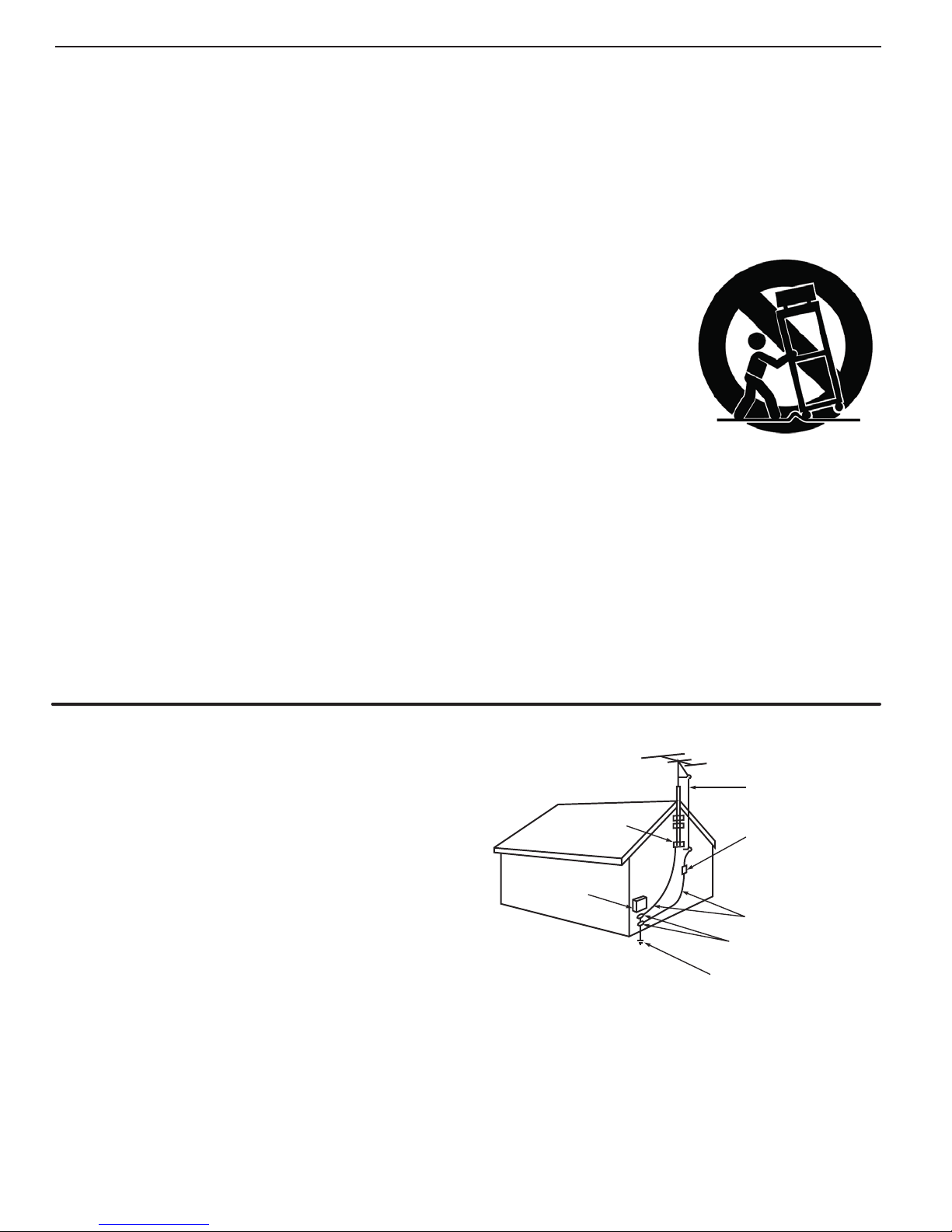
Outdoor Antenna Grounding
If an outside antenna or cable system is connected
to the TV, be sure the antenna or cable system is
grounded so as to provide some protection against
voltage surges and built-up static charges.
Replacement Parts
When replacement parts are required, be sure the
service technician has used replacement parts specified by the manufacturer or have the same characteristics as the original part. Unauthorized substitutions
may result in fire, electric shock or other hazards.
%8!-0,%/&!.4%..!'2/5.$).'
'2/5.$#,!-0
%,%#42)#
3%26)#%
%15)0-%.4
.%#.!4)/.!,%,%#42)#!,#/$%
!.4%..!
,%!$).7)2%
!.4%..!
$)3#(!2'%5.)4
.%#!24)#,%
'2/5.$).'
#/.$5#4/23
.%#!24)#,%
'2/5.$#,!-03
0/7%23%26)#%'2/5.$).'
%,%#42/$%3934%.%#!240!24(

5
In stallation Notes
Wall Mount Requirements
For wall-mounting, see “Stand Removal,” page 11 .
Use with other than the authorized accessories
may cause the TV to become unstable, which can
cause damage to the product or possible injury.
Custom cabinet installation must allow for proper
air circulation around the television.
NOTE TO CATV SYSTEM INSTALLER: THIS REMINDER
IS PROVIDED TO CALL THE CATV SYSTEM INSTALLER’S
ATTENTION TO ARTICLE 820-40 OF THE NEC THAT PROVIDES GUIDELINES FOR THE PROPER GROUNDING AND,
IN PARTICULAR, SPECIFIES THAT THE CABLE GROUND
SHALL BE CONNECTED TO THE GROUNDING SYSTEM OF
THE BUILDING, AS CLOSE TO THE POINT OF CABLE ENTRY
AS PRACTICAL.
If Your TV Gets Damaged
Crystalline liquid may leak from the LCD panel and
broken glass may be scattered.
CAUTION: The crystalline liquid is toxic. Avoid
contact with your skin, eyes, or mouth. DO NOT
touch the broken glass or crystalline liquid. DO NOT
get glass fragments or crystalline liquid into eyes or
mouth. Should either contact with your eyes or
mouth, rinse the contacted area thoroughly with
water and consult your doctor.
Cl eaning Recommendations
Normally, light dusting with a dry, non-scratching duster
will keep your TV clean. If cleaning beyond this is
needed, please use the following guidelines:
First, turn off the TV and unplug the power cord from
the power outlet.
Top and Sides of the TV
Occasionally clean dust build-up from the air-intake •
grilles on the back and sides of the TV. Clean using
a vacuum cleaner with a brush attachment.
Gently wipe down your TV with a soft, non-abrasive •
cloth such as cotton flannel or a clean cloth diaper,
lightly moistened with water. Dry with a second dry,
soft, non-abrasive cloth.
For oily dirt, add a few drops of mild liquid deter-•
gent, such as dishwashing detergent, to the water
used to moisten the cloth. Rinse with a second
cloth moistened only with water. Dry with a third
dry, soft, non-abrasive cloth.
Glossy Surfaces: • Take special care when cleaning
the TV’s glossy surfaces.
Always shake or brush the cleaning cloth first to -
remove any dirt particles.
Wipe the glossy areas gently, without applying -
pressure.
If necessary, lightly dampen the cloth with water. Use no chemical or abrasive cleaners.
Disposal of Your TV
The LCD panel contains a small amount of crystalline
liquid and the fluorescent tube in the panel contains
mercury. Both are toxic and should not be touched.
DO NOT dispose of the TV with general household
waste. THE LAMPS INSIDE THIS PRODUCT CONTAIN
MERCURY AND MUST BE RECYCLED OR DISPOSED
OF ACCORDING TO LOCAL, STATE, AND FEDERAL
LAWS. For disposal or recycling information, contact
your local authorities or the Electronic Industries Alliance at www.eiae.org.
TV Software
Do not attempt to update the software of this TV with
software or USB drives not provided by or authorized by
Mitsubishi Digital Electronics America, Inc. Non-authorized
software may damage the TV and will not be covered by
the warranty.
TV Guide Daily Access Requirements
TV Guide Daily listings are not provided by Mitsubishi Digital
Electronics America, Inc. Operation of TV Guide Daily
requires over-the-air or direct cable (no cable box) access to
stations carrying TV Guide Daily program listings. If listings
are not available in your area or become discontinued by the
local provider, TV Guide Daily will not operate. TV Guide Daily
does not provide program listings for satellite TV systems.
LCD Screen Cleaning
IMPORTANT
DO NOT apply any type of liquid to the surface of
the TV screen.
• Use only use a soft, dry cloth to clean the LCD
screen. Do not use any liquids.
• Wipe the screen gently with an up and down
motion.
• Clean the entire screen evenly, not just sections of
the screen.
General Cleaning Precautions
• DO NOT allow liquid to enter the TV through the
ventilation slots or any crevice.
• DO NOT use any strong or abrasive cleaners, as
these can scratch the surfaces.
• DO NOT use any cleaners containing ammonia,
bleach, alcohol, benzene, or thinners, as these can
dull the surfaces.
• DO NOT spray liquids or cleaners directly on the
TV’s surfaces.
• DO NOT scrub or rub the TV harshly. Wipe it gently.
6
1
Television Overview
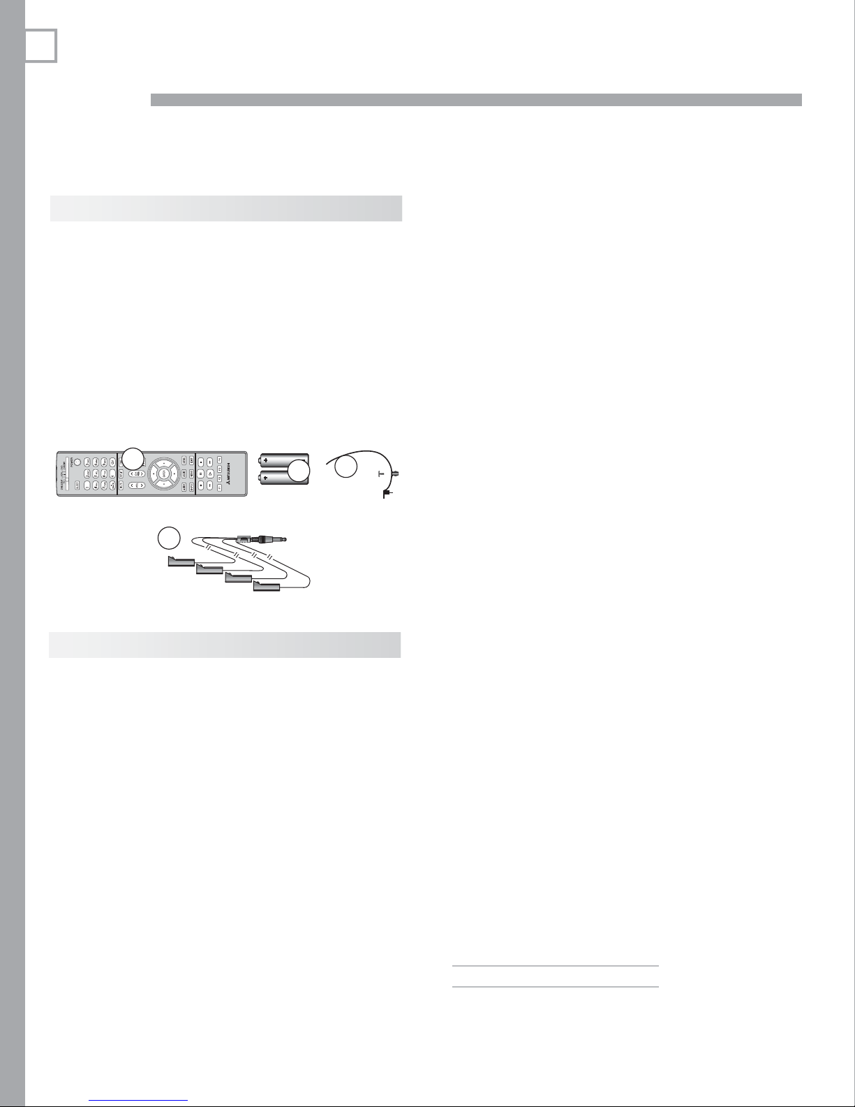
Package Contents
Please take a moment to review the following list of
items to ensure that you have received everything.
Remote Control1.
Two AA Batteries2.
Cable Tie with Pin3.
Owner’s Guide4.
Quick Reference Guide5.
Quick Connect Guide6.
Product Registration Card7.
Four-ended IR emitter cable8.
1
8
AA
2
AA
3
Special Features of Your TV
Your new high-definition widescreen television has
many special features that make it the perfect center of
your home entertainment system, including:
1080p High-Definition LCD Display System
Your Mitsubishi LCD Flat Panel HDTV uses a full 1920
x 1080 LCD panel to create the picture you see on the
screen. All images are displayed at 1080p. The TV
uses Plush 1080p™ to convert lower-resolution signals
to 1080p for display.
Smooth120Hz™ Film Motion
Smooth120Hz™ Film Motion makes fast-moving images
appear smoother and more fluid, free from motion
blur. In this LCD Flat Panel HDTV, Smooth120Hz™
Film Motion doubles the traditional progressive scan
frame rate and creates new frames of video between
the traditional frames to smooth moving images.
Smooth120Hz™ Film Motion also smooths film judder
(image vibration) that may be present in film-based
content such as movies.
16:9 Widescreen Picture Format
Enjoy a full theatrical experience in the comfort of your
home. View pictures as film directors intended them.
Digital TV broadcasts, DVDs and newer video game
consoles support this widescreen format.
Integrated HDTV Tuner
Your widescreen Mitsubishi HDTV has an internal HDTV
tuner able to receive both over-the-air HDTV broadcasts (received via an antenna) and non-scrambled
digital cable broadcasts, including non-scrambled
HDTV cable programming.
High-Definition Video Inputs
Component Video Inputs.• Also called Y/Pb/Pr
inputs, these inputs receive standard analog video
formats of 480i, 480p, 720p, and 1080i high-definition signals. This provides a high level of flexibility
when connecting DVD players/recorders, cable
boxes, and satellite receivers.
HDMI Inputs.• These inputs accept digital 480i,
480p, 720p, 1080i, and 1080p video signals plus
PCM digital stereo signals. The HDMI™ inputs can
also accept a variety of PC signals and resolutions.
These inputs support HDMI 1.3 Deep Color (up to
36 bits) and the x.v.Color extended color gamut.
Used with an adapter, these inputs also accept
compatible digital DVI video signals. HDMI
inputs provide additional high-performance,
high-definition connections for maximum flexibility
in your choice of home theater products. The HDMI
inputs are HDCP copy-protection compatible.
Easy Connect Auto Input Sensing
Easy Connect™ Auto Input Sensing automatically recognizes when you plug in an input and prompts you to
assign a name to it. The TV ignores any unused inputs,
so the result is an uncluttered Input Selection menu
where you can easily find and select connected devices
by name.
Home Theater Control
Net Command with IR Learning
Your Mitsubishi HDTV offers a new level of networking
that seamlessly integrates selected older A/V products
with new and future digital products. Net Command®
supports IR (infrared) control of products such as VCRs,
1. Television Overview 7
SYSTEM
RESET
DVD players, cable boxes, and satellite receivers. Net Command can “learn” remote control signals directly
from many devices, allowing you to create a customized NetCommand-controlled home-theater system.
POWER
SYSTEM
RESET
VOL
VOL
ADJ
ADJ
CH
ADJCHADJ
FORMAT
FORMAT
ENTER
ENTER
MENU
MENU
MENU
MENU
GUIDE
GUIDE
CANCEL
CANCEL
INPUT
INPUT
Net Command for HDMI
HDMI devices with Consumer Electronics Control (CEC)
capabilities may be compatible with the TV’s Net Command for HDMI feature. Compatible devices can
receive control signals through the HDMI connection.
GalleryPlayer
GalleryPlayer allows you to transform your TV into
an art showcase. Beautiful high-definition images
to display on your TV are available for purchase at
Mitsubishi.GalleryPlayer.com. Several sample images
are provided with the TV. See page 49 .
TV Guide Daily Interactive
Program Guide System
The TV Guide Daily system is an on-screen program
guide for cable and over-the-air reception. This
subscription-free guide system lists regular, digital,
and high-definition programming. Note that when the
system is first set up, it may take up to 24 hours to
begin receiving TV program listings.
System Reset Button
If the TV fails to respond to the remote control, control-panel buttons, or will not power on/off, press the
SYSTEM RESET
button on the control panel.
The LED on the front panel will flash quickly for about
one minute. When the LED stops flashing, you may turn
on the TV. Recent setting changes you made before
using
SYSTEM RESET
may be lost.
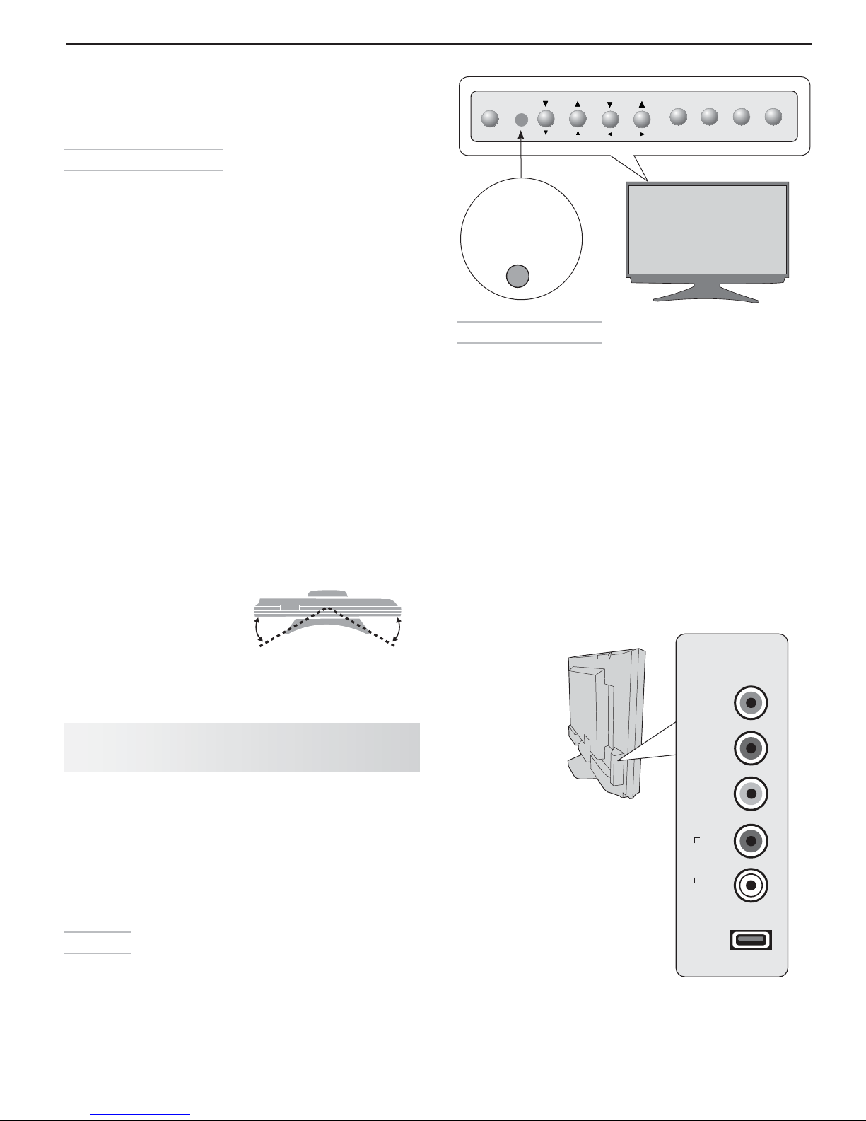
Convenience Inputs
Swivelling Stand
The included stand
allows the TV to be swiveled manually up to 30
degrees left or right to the
best viewing angle.
TV Control Panel and
Convenience Inputs
Control Panel
Buttons on the control panel duplicate commonly used
keys on the remote control. The upper labels show
control functions when no TV menus are displayed; the
lower labels indicate functions when TV menus are displayed or when a special function has been activated.
See “Remote Control,” page 30 , for a full description of
the functions of these buttons.
A/V Reset
If you wish to reset the A/V (Audio/Video) settings back
to the factory defaults:
• To reset all settings at once, press
on the control panel at the same time.
•
To reset the defaults for individual inputs, use the
Reset selection on the AV menu. See “AV Menu,”
page 38 .
Top View
30° 30°
Front
The TV can be swiveled
up to 30 degrees left or
right.
GUIDE
and
FORMAT
INPUT 4
• is a readily accessible set of input jacks for
a camcorder, game, or other audio/video device.
A USB photo port lets you view JPEG images from •
a USB drive or card reader.
INPUT 4
Pr
Pb
Y/
VIDEO
Note:
To connect a standard video
device (composite video):
connect the single (yellow)
video cable to the
jack
.
Y/VIDEO
R
OIDUA
L
USB
8 1. Television Overview
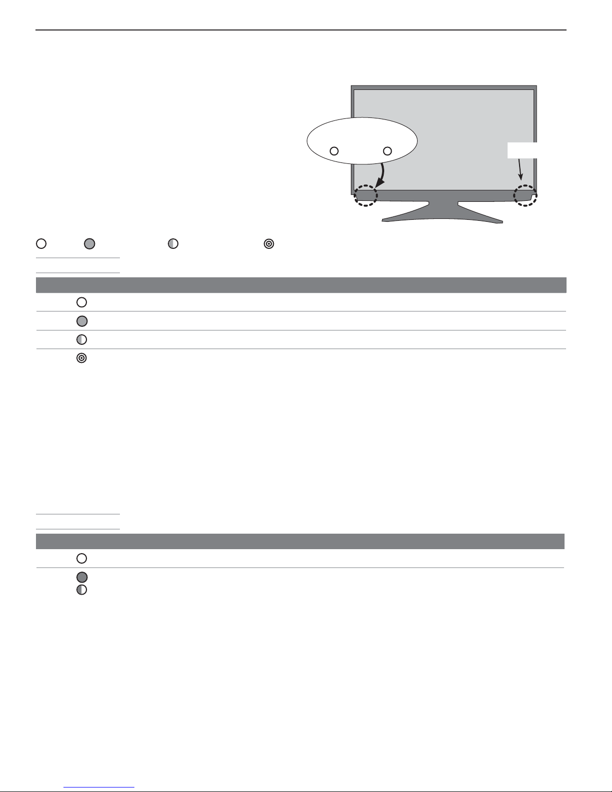
STATUSPOWER
Front-Panel Indicators
STATUS•
operation.
POWER/TIMER• indicator. Lit when TV is
powered on; flashes when TV is powered
off and the auto-on TV Timer is set
IR Sensor• (Infrared Sensor). Detects infra-
red signals emitted by the remote control.
Off Steady On Slow Blinking Fast Blinking
POWER Indicator
LED Color TV Condition Additional Information
None
Green
Green
Green
indicator. Off during normal TV
.
Standby condition. Normal operation.
TV is powered on.
TV powered off, auto-on timer is set.
1. TV just plugged into AC outlet.
2.
AC just restored after power failure.
3. TV rebooting after System Reset
used.
4. TV rebooting after power fluctuation or receiving abnormal
digital signals from a digital
channel or digital device.
5. You have begun the procedure
to update software from an
authorized flash memory device.
Normal operation.
Normal operation. TV can be turned on at any time.
Wait approximately one minute for blinking to stop before turning
on. Normal operation.
IR Sensor
STATUS Indicator
LED Color TV Condition Additional Information
None
Red
Normal TV on or standby condition.
TV may require service.
Normal operation.
Turn off the TV and unplug the set from the AC power source.
Wait one minute and then plug the set back in. See Appendix F .
If the LED is still on, contact your dealer, go to
www.mitsubishi-presentations.com, or call (888) 307-0309 to
receive authorized service information.
1. Television Overview 9
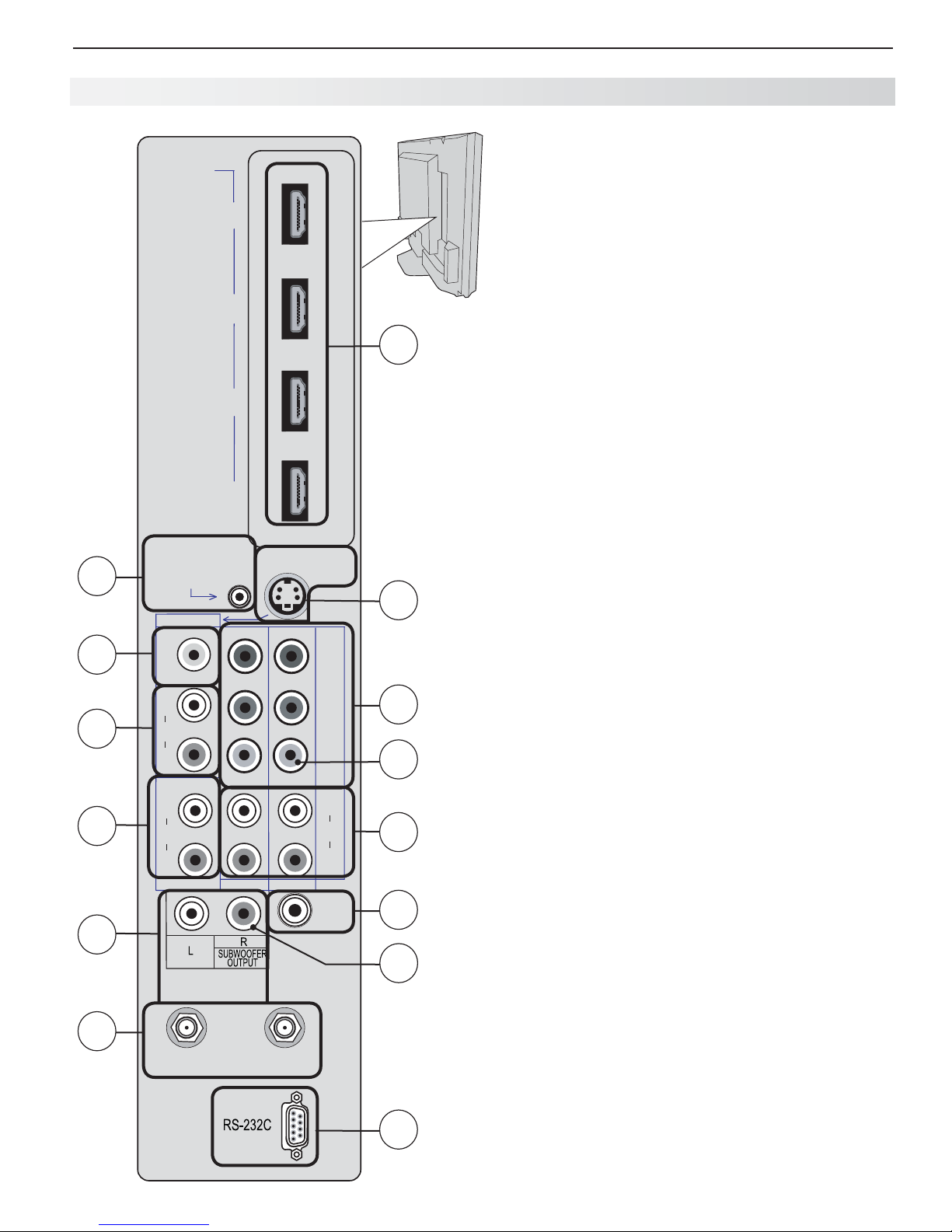
TV Main Panel
1. ANT 1/ANT 2 ( Antenna)
If you are connecting an antenna or direct cable service
without a cable box, connect the main antenna or cable
source to
ANT 1
and
ANT 1
. Use
ANT 2
for a second source.
ANT 2
can each receive digital and analog
over-the-air channels from a VHF/UHF antenna or nonscrambled digital/analog cable source.
ANT 1/MAIN and CableCARD™
Use
INPUT 1
INPUT 1
ANT 1/MAIN
or
to receive premium subscription
AUDIO R
INPUT 2
if you wish to send audio to the TV.
INPUT 1
and L
component
video (Y Pb Pr) or composite video (single yellow cable).
INPUT 2
INPUT 2
component
video exclusively.
AUDIO R
INPUT 3
VIDEO
(item 6) if you wish to send audio to the TV.
jacks to connect a VCR, Super VHS (S-VHS)
AUDIO R
and L inputs for
INPUT 1
if you wish to send audio to the TV. Note that the
S-VIDEO
.
and L
or
INPUT
12
5
6
7
9
HDMI
VIDEO: 480i,
480p /720p
1080i /1080p
AUDIO:
PCM STEREO
PC: VGA,
W-VGA, SVGA,
W-SVGA, XGA,
W-XGA, SXGA /
720p/1080p
NetCommand
IR-
Output / External
Controller Input
INPUT3
VIDEO
L
AUDIO
R
DVI/PC
L
AUDIO
R
L
4
3
2
1
S-VIDEO
Y
Y / VIDEO
INPUT2 INPUT1
R
) i 0 8 0 1 / p 0 2 7 / p 0 8 4 / i 0 8 4 (
Pr
Pb
L
AUDIO
R
DIGITAL
AUDIO
OUTPUT
8
4
2
5
3
11
cable TV service authorized by the CableCARD™ access card.
The CableCARD access card is provided by your local cable
company.
2. Component Video (INPUT 1, INPUT 2)
Y Pb Pr Component Video (480i/480p/720p/1080i)
Use these jacks to connect devices with component video
outputs, such as DVD players, external HDTV receivers, or compatible video game systems. Use the adjacent
jacks for
See Appendix A specifications for signal compatibility.
3. AUDIO L and R (INPUT 1, INPUT 2)
Analog stereo inputs shared by more than one video input.
• audio jacks are for use with
• audio jacks are for use with
4. S-VIDEO (INPUT 3)
Connect an S-Video device to this input. Use the
jacks for
5. Composite Video (INPUT 1, INPUT 3)
Use the
VCR, DVD player, standard satellite receiver, or other A/V device
to the TV. Use the adjacent
INPUT 3
3
composite video jack is automatically disabled when you
connect to
AVR AUDIO
OUTPUT
1
ANT2/AUX
ANT1/MAIN
10
13
6. AUDIO L and R (INPUT 3)
Analog stereo inputs shared by
S-VIDEO
.
INPUT 3
composite video and
7. DVI/PC INPUT AUDIO
Use the
to one of the TV’s HDMI inputs using a DVI-to-HDMI cable.
These jacks allow you to send left and right analog audio from
your computer or other DVI device to the TV.
DVI/PC INPUT AUDIO
jack when connecting a DVI device

10 1. Television Overview
TV Main Panel, continued
8. HDMI™ Inputs
(High-Definition
Multimedia Interface)
The HDMI inputs support uncompressed standard and highdefinition digital video formats and PCM digital stereo audio.
Use the HDMI inputs to connect to CEA-861 HDMI compliant devices such as a high-definition receiver or DVD player.
These inputs support 480i, 480p, 720p, 1080i, and 1080p
video formats.
Mitsubishi recommends you use category 2 HDMI cables,
also called high-speed HDMI cables, to connect HDMI 1.3
source devices. High-speed category 2 cables bring you
the full benefits of Deep Color and x.v.Color.
These HDMI inputs can also accept digital DVI video signals.
To connect a DVI input, use an HDMI-to-DVI adapter or
cable plus analog audio cables. Connect the analog audio
cables to the DVI/PC INPUT AUDIO jacks on the TV to
receive left and right stereo audio from your DVI device.
The TV’s HDMI inputs are compatible with many DVI-D and
HDMI computer video signals. For additional information on
PC compatibility, see “Using the TV with a Personal Computer,” page 18 , and Appendix A , “Specifications,” page 66 .
These inputs are HDCP (High-Bandwidth Digital Copy Protection) compliant.
9. AVR AUDIO OUTPUT
Use
AVR AUDIO OUTPUT
program currently shown on the screen to an analog A/V
surround sound receiver or stereo system. Digital audio
from digital channels and HDMI devices is converted to
analog audio by the TV. This is the only audio connection needed between it and the TV if using an analog A/V
receiver or stereo system.
Selecting Audio Output Types
The red audio jack can output either right stereo
audio for an A/V receiver or mono bass audio
for a subwoofer. Select the output type when
prompted in the Auto Output Sensing screen.
to send analog audio of the
IMPORTANT
10. SUBWOOFER OUTPUT
Connect a powered subwoofer to the
OUTPUT
Sensing screen displays.
jack. Select Subwoofer when the Auto Output
SUBWOOFER
11. DIGITAL AUDIO OUTPUT
This output sends Dolby Digital or PCM digital audio to
your digital A/V surround sound receiver. Analog audio
from analog channels and devices is converted by the TV
to PCM digital audio. If you have a digital A/V receiver,
in most cases this is the only audio connection needed
between the TV and your A/V receiver.
H DMI Cable Categories
HDMI cables are available as Category 1 and Category 2
types.
Category 2 Cables• (also called high-speed HDMI
cables). Newer, HDMI 1.3-compliant DVD players,
video games, and set-top boxes require Category 2
cables, suitable for clock frequencies up to 340 MHz
or data rates of up to 10.2 gigabits per second. Use
category 2 cables for high-speed 1080p HD signals
carrying extended color encodings (i.e., 30 or more
bits, also called Deep Color). Category 2 cables are
also suitable for standard HDTV signals.
Category 1 Cables• (also called standard HDMI
cables). Category 1 cables may be unmarked. They
are suitable for standard HDTV 720p and 1080i
signals with 8-bit color depth. Use category 1 cables
for clock frequencies up to 74.25 MHz or data rates
of up to 2.23 gigabits per second.
12. IR NetCommand Output/External
Controller Input
IR emitters connected to this jack are used by the TV’s
Net Command system to send control signals to external IR
remote-controlled devices such as cable boxes, VCRs, DVD
players, satellite receivers and audio receivers.
When Net Command is not in use, this jack can be switched
to receive wired IR control signals from external system controllers. To switch this jack to an input, connect the external
controller’s IR output to this jack, then:
Press 1.
MENU
to display the TV menu.
Enter the number sequence 2, 4, 7, 0 to display the 2.
Installer menu.
Highlight the 3. WIRED IR selection and press
change the setting from OFF to ON.
To revert to NetCommand control:
Disconnect the IR device.1.
Press 2.
MENU
to display the TV menu.
Enter the number sequence 2, 4, 7, 0 to display the 3.
Installer menu.
Highlight the 4. WIRED IR selection and press
change the setting from ON to OFF.
Note: When the WIRED IR option is set to ON (control
by an external device), the Low Power setting for
Energy Mode is unavailable.
ENTER
ENTER
to
to
13. RS-232C
Use the RS-232C interface to receive control signals from
compatible home-theater control devices.
1. Television Overview 11
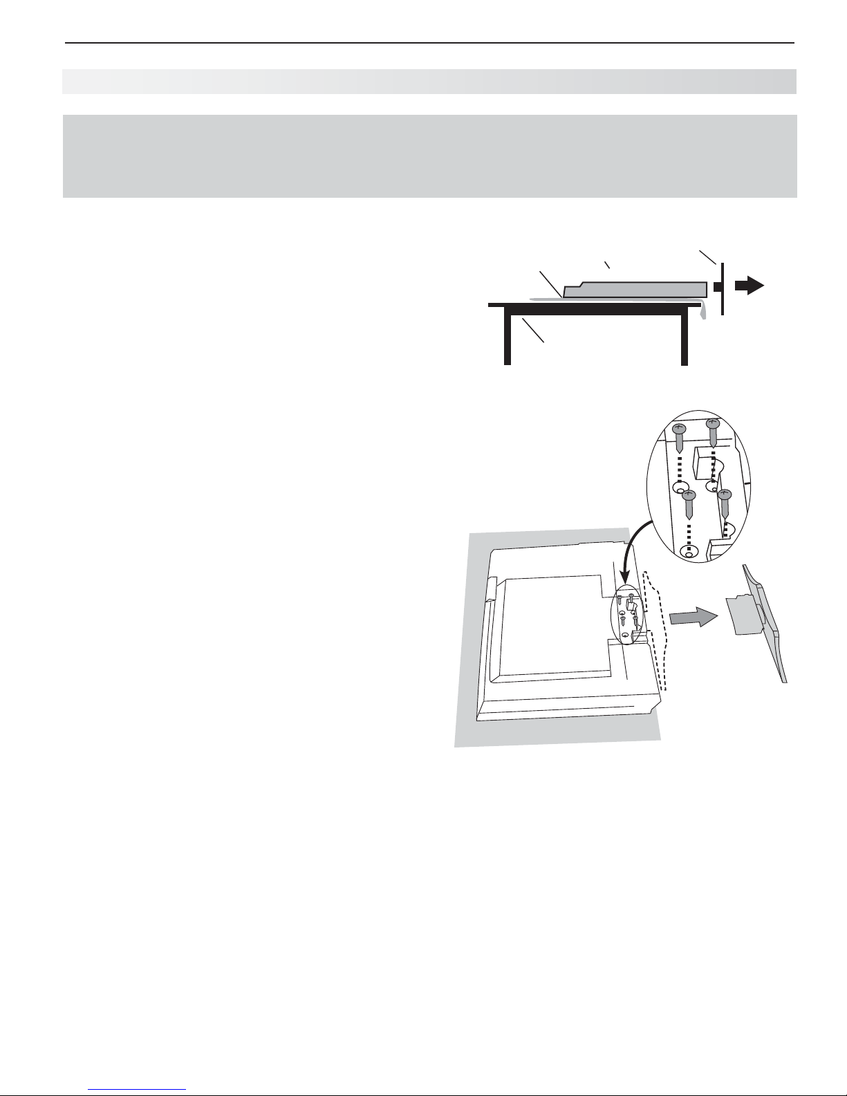
S tand Removal
CAUTION
At least TWO PEOPLE are needed to safely remove the stand. Have one person hold the TV while the other
person removes the stand. Failure to follow these recommendations may result in personal injury and
damage to the product.
Stand-Removal Procedure:
Disconnect the TV’s AC power cord from the AC
1.
power outlet.
Spread the protective sheet that was wrapped
2.
around the TV on a flat, even surface, such as a
sturdy table. The protective sheet will help prevent
damage to the display.
IMPORTANT: To avoid damaging the screen,
make sure there are no foreign objects under or
on top of the protective sheet.
Position one person on each side of the TV (left and
3.
right sides). Have each person firmly grasp their
side of the TV and gently place it face down on the
protective sheet with the display stand hanging over
the edge of the table. See the illustration to the
right.
Use a magnetic philips screwdriver to remove the
4.
four stand screws from the recessed holes (see
illustration to right). Note: A regular screwdriver
can be used with a separate magnetic pick-up tool.
While one person holds the TV with both hands,
5.
have the other person grasp the plastic portion of
the stand (see illustration to the right) and remove
the stand by pulling it away from the TV in the direction of the large arrow shown in both illustrations.
The TV is now ready for wall mounting. See “Wall
6.
Mount Kit” below.
1SPUFDUJWF
TIFFU
5BC M F
TV Back
Cover
57
4UBOE
Wall Mounting Kit (purchased separately)
To order a Wall Mounting Kit, please contact Peerless
Industries, Inc. at (800) 473-3753 or visit www.peerlessmounts.com. Use wall mounting kit Model ST650.
Note: Complete instructions are included with the kit.
To order a Wall Mounting Kit from Mitsubishi Digital
Electronics America, Inc., please visit
www.mitsubishi-presentations.com or call
(888) 307-0349.
Protective Sheet
CAUTION: Using this TV with other than the authorized accessories may cause the TV to become
unstable, which can cause damage to the product
or possible injury.
12
TV Set-Up
2
G uidelines for Setting Up and Using Your New Widescreen TV
Getting Started
Review the important safety, installation, and oper-1.
ating information at the beginning of this book.
Choose a location for your TV.2.
Allow at least four inches of space on all sides •
of the TV to help prevent overheating. Overheating may cause premature failure of the TV.
Avoid locations where light may reflect off the •
screen or where the TV is exposed to direct
sunlight.
Refer also to • “Installation Notes,” page 5 .
Install the batteries in the remote control. See 3. this
page for instructions. See page 30 for more on use
of the remote control.
Plug your TV into a power outlet. The green LED on 4.
the front of the TV will start blinking rapidly. After
the green LED stops blinking, press the
power on the TV.
When the 5. Welcome screen appears the first time
you power on the TV, select a language for TV
menus. You can later change the language through
the Setup menu.
Connect your audio/video (A/V) devices to the TV 6.
and perform initial setup.
See chapter 3, “TV Connections,” for connec-•
tion diagrams.
See the following pages for initial TV setup and •
use of the Auto Input Sensing feature.
To connect the TV to a personal computer, see •
“Using the TV with a Personal Computer,” page
18 .
See chapter 6, “Net Command IR Control,” to •
perform Net Command IR “learning” to set up
control of your home theater.
To set up NetCommand HDMI control of CEC-•
enabled devices, see Appendix E .
Mitsubishi recommends you perform a channel 7.
scan for channels received on
See “Initial TV Setup” page 14 .
You can now start watching TV or you can perform 8.
additional setup and customization through the TV
menus.
ANT 1
and
POWER
ANT 2
key to
.
Turning the TV On or Off
To turn the TV on or off, point the remote control at the
front of the TV and press the
tively, press the
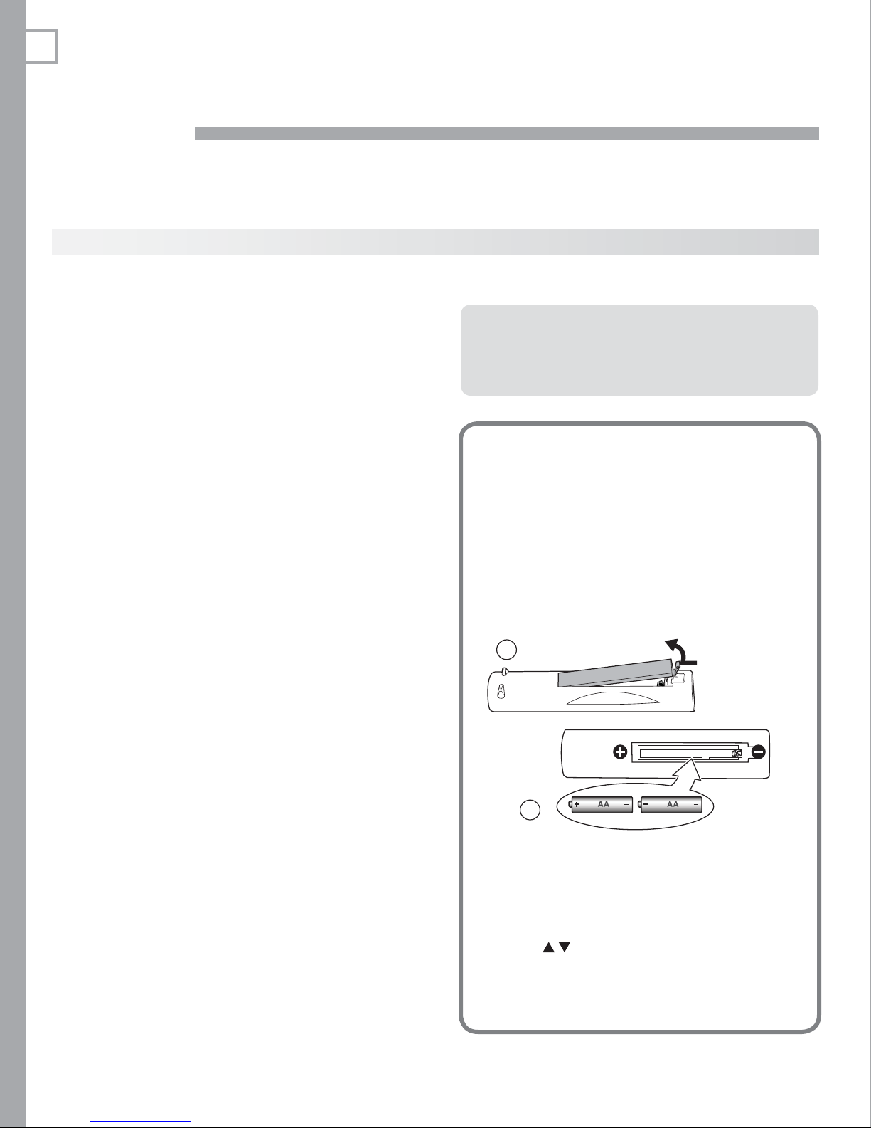
Installing the R emote Control
Batteries
Remove the remote control’s back cover by
1.
gently pressing in the tab and lifting off the
cover.
Load the batteries, making sure the polarities
2.
(+) and (-) are correct. For best results, insert
the negative (-) end first.
Snap the cover back in place.
3.
1
2
When You First Power On the TV
Choosing a Language for Menus
Power on the TV for the first time.
1.
Press
2.
for all menus. You can later change the language selection through the Setup > Lan-
guage menu. See page 44 .
POWER button. Alterna-
POWER button on the TV’s control panel.
The remote
control requires
two AA alkaline
batteries.
to select either English or Spanish

2. TV Setup 13
Additional TV Setup
Review chapter 5, “TV Menus,” to customize TV 1.
operation. Press the
system. Some examples of settings you may wish
to change include:
• Fav. Use an on-screen menu to create custom
lists of your favorite channels from
ANT 2
. See Setup > Edit, page 45 .
• Order. Rearrange the device icons in the Input
Selection menu to put frequently used icons
near the front. See Inputs > Order, page 50 .
• Name. Change the device types that appear
in the Input Selection menu. See Inputs >
Name options, page 50 .
• Parental Locks. Restrict TV viewing by
program rating, by channel, or by time of day.
You can also disable the control-panel buttons
if you have small children.
To restrict TV use by program rating, see the Lock > Parent menu, page 52 .
To lock the control-panel buttons, use the Lock > Control Panel menu, page 53 .
To restrict TV use by channel, see - Setup >
Edit > Lock, page 45 .
• Video Settings. Change video adjustments to
get the best picture for your viewing conditions.
See “AV Menu,” page 38 .
MENU
key to enter the menu
ANT 1
and
TV Operation
Review chapter 4, “TV Operation and Features,” for 1.
TV features including:
• Input Selection (viewing source). Select a
connected program source to watch, such as a
VCR, DVD player, or antenna. Press
remote control to select from icons for the TV
inputs. See “Choosing a Viewing Source,” page
29 .
• Listings. Press
For ChannelView™ display of listings on
ANT 1
Channel Listings,” page 31 .
If you have set up and activated the TV Guide Daily system, press the
display listings using TV Guide Daily. See
Appendix D ,
• Picture Formats. Press
picture sizes and shapes to find the one best
suited to the current program. See “TV Signals
and Display Formats,” page 34 .
To view still and moving digital camera images on 2.
the TV, see page 35, “Viewing Camera Files and
GalleryPlayer Images .”
To control A/V devices with Net Command, see 3.
page 58, “Operating NetCommand-Controlled
Devices .”
and
GUIDE
.
ANT 2,
see “ChannelView
GUIDE
FORMAT
to cycle through
INPUT
key to
on the
Note: You may wish to change the Picture Mode from
the default Brilliant to either Bright or Natural,
which are suitable for most home viewing.
To see a demo of beautiful images in high-definition 2.
from the Mitsubishi.GalleryPlayer.com collection,
see page 49 .
To program the remote control to operate A/V 3.
devices not under Net Command control, see
Appendix C , “ Programming the Remote Control .”
To set up the TV Guide Daily system, see Appendix 4.
D .
TV Cleaning
See “Cleaning Recommendations,” page 5 .
Assistance
• For troubleshooting, service, and product
support, see Appendix F .
• For warranty information, see the TV warranty
on page 92 .
14 2. TV Setup
Initial TV Setup
Use the Setup menu for basic TV setup options.
Press
1.
2.
M emorizing Channels
For ANT 1 and ANT 2
Note: I
To start channel memorization
1. ANT 1
2.
Start channel memorization from the Setup menu.
MENU
to open the Main menu.
Press
Setup menu.
Connect the incoming cable to
This is the cable from an antenna or a cable service
without a cable box.
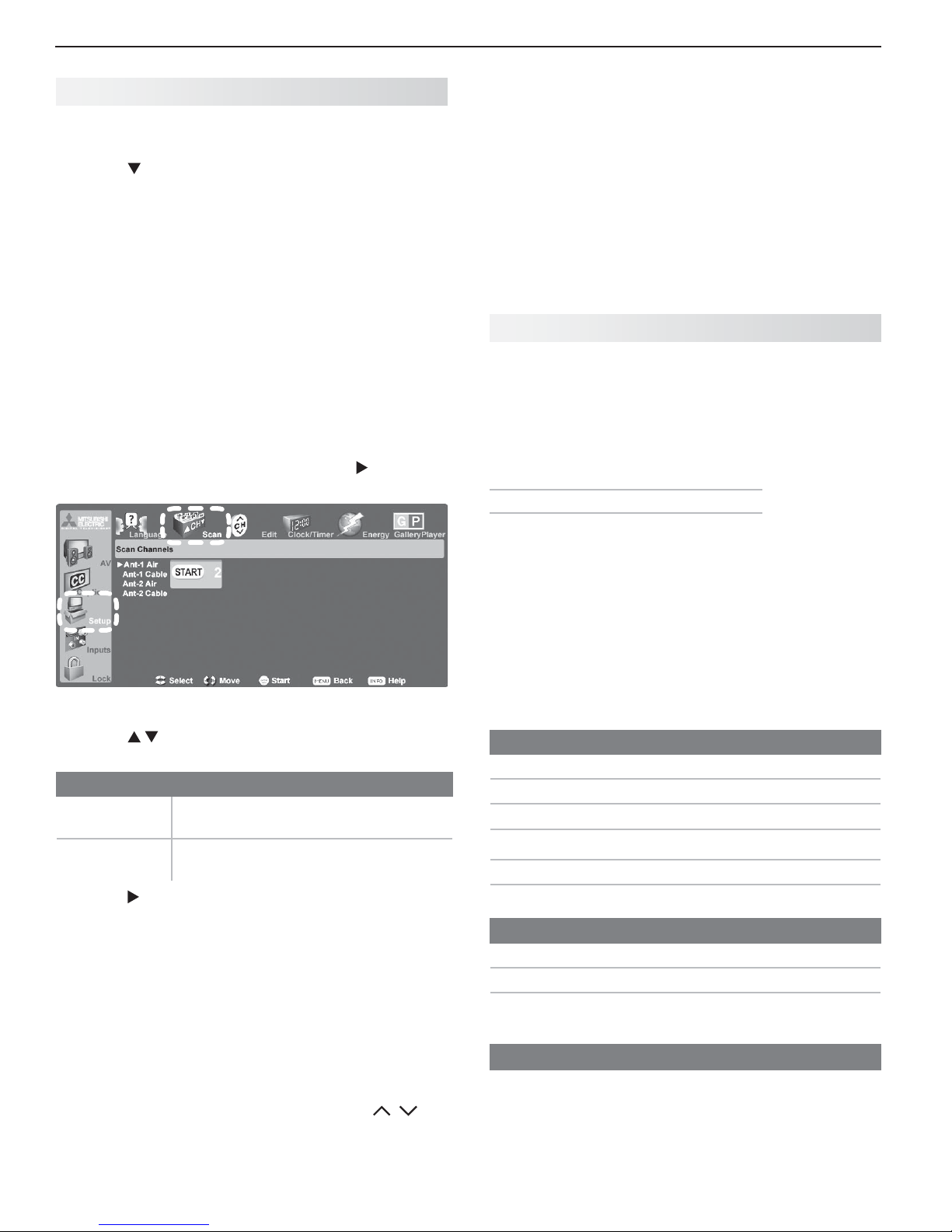
With the
light the Scan icon.
to highlight the Setup icon and display the
f using a CableCARD, the TV will automatically
acquire the complete list of available channels
from the service provider. Perform channel
memorization for
if you need to reacquire the channel list.
Setup menu displayed, press to high-
ANT 1
CableCARD service only
or
ANT 2
.
• Use the Setup > Edit menu ( page 45 ) for additional
channel options, such as adding or deleting channels from memory, naming channels, and saving
favorite channels in custom memory banks.
See chapter 5, “TV Menu Settings,” to:
• Set the TV clock ( page 46 )
• Set the TV Timer ( page 47 ) to have the TV power on
at a preset time.
• Select an Energy Mode to manage power use while
the TV is off ( page 48 ).
Setting Up TV Inputs
When You First Connect a Device
The TV’s Easy Connect™ Auto Input Sensing feature
detects most connections automatically.
Note: For connection and setup of a personal com-
puter, see the information on page 18 .
Auto In put Sensing for Most Devices
When you first connect a device, the TV will:
a. Detect the connection and automatically switch
to the input
b. Prompt you to identify the device type (if not
recognized automatically)
c. Prompt you to perform Net Command set-up for
the device, if available
d. Repeat these steps for any additional newly
detected devices
See below for connections which trigger Auto Input Sensing.
Press
3.
your connections:
Input Condition
Ant 1 Air
Ant 2 Air
Ant 1 Cable
Ant 2 Cable
Press
4.
Press
5.
tion.
To stop channel memorization before
completion, press
When memorization is complete you can:
6.
• Press
• Press
• Press
After channels have been memorized:
• To tune to memorized channels, press
while watching TV on the
to highlight an input selection based on
When connected to an indoor or
outdoor antenna
When connected to direct cable (no
cable box)
to highlight the on-screen START button.
ENTER
to start automatic channel memoriza-
CANCEL
.
MENU once to return to the top row of icons.
MENU again to return to the Main menu.
EXIT
to watch TV.
ANT 1
or
ANT 2
CH
/
input.
Auto Input Sensing Available
Y/VIDEO
Y/VIDEO
S-VIDEO
HDMI
USB (USB photo port)
INPUT 4 AUDIO (with video plug, see page 28 .
Auto Output Sensing
DIGITAL AUDIO OUTPUT
AVR AUDIO OUTPUT (red jack)
AVR AUDIO OUTPUT/
SUBWOOFER OUTPUT
No Auto Sensing
ANT 1
*
(detected as
plus Pb (detected as component video)
composite video)
*
Available
(orange jack)
(
red jack)
and
ANT 2
If the device is powered off when connected, detection occurs when the device is next powered on.
2. TV Setup 15
Setting Up TV Inputs, continued
Auto Input Sensing for CEC-Enabled Devices
When the TV’s NetCommand for HDMI feature is
enabled, most CEC-enabled devices are recognized
and identified automatically by the TV. Net Command
for HDMI may allow you to control functions of a CECenabled device. See Appendix E , page 80 .
Setup Procedure
Power on the TV.
1.
Connect your devices to the TV, making note
2.
of which TV input is used for each device. See
chapter 3, “TV Connections.”
Note: If you wish to use an HDMI device’s CEC capa-
bilities, follow the steps in Appendix E
First select a
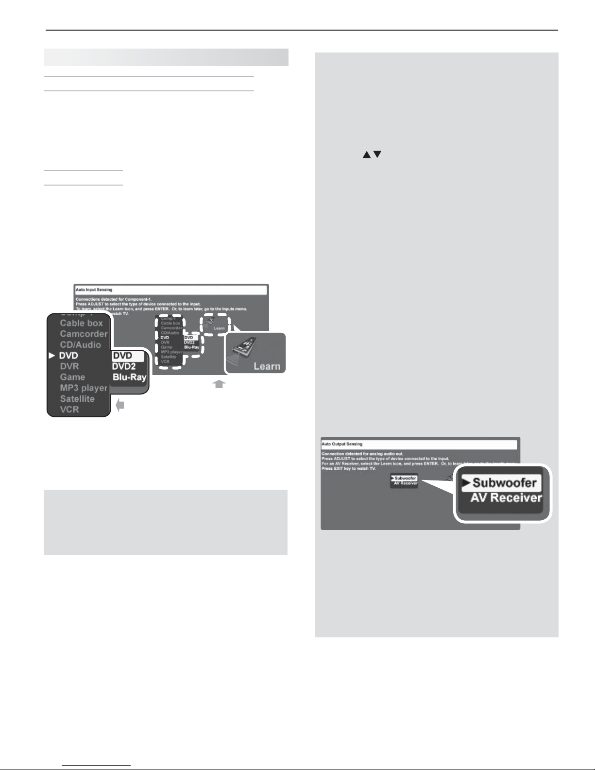
device type.
Sample Auto Input Sensing screen.
.
Next perform
IR “learning” if
available.
Auto Input/Auto Output S ensing Screens
See below for how different connections are handled
by Auto Input/Auto Output Sensing.
Most Device Types.• Select the device type
from the on-screen list.
here will appear as an icon in the Input Selection
menu.
Press
the device type connected to the input. Some device
types also display a
if using more than one of the same device. See
the sample Auto Input Sensing screen shown.
A/V Receiver•
Sub woofer.• With the subwoofer connected to
the
Subwoofer when the Auto Output Sensing
screen displays. With this setting, a limited
range of bass frequencies is passed to the subwoofer.
to move through the device list to highlight
The TV detects audio connections on the -
DIGITAL AUDIO OUTPUT jack and the right (red)
AVR AUDIO OUTPUT jack.
If using an analog A/V receiver, highlight - AV
Receiver when the Auto Output Sensing
screen displays. This setting causes the TV
to pass the full range of stereo sound to the
A/V receiver.
For an HDMI connection, select - AVR from
the list of device types if the A/V receiver is
not recognized automatically.
right (red) AVR AUDIO OUTPUT jack,
The device type you select
sub-menu of names—useful
highlight
When the TV detects a new connection, the
3.
Sensing screen for the connection type will display.
Select the device type if required.
Important Note for NetCommand IR Users
Be sure to select the correct device type here.
Although you can change the device type later in the
Inputs > Name menu, any “learned” Net Command
IR codes will be erased when you make the change.
You can perform Net Command IR “learning” after
4.
selecting the device type or at a later time when
convenient. To perform now, highlight the Learn
icon and press
Setup for Most Devices,” page 56 or “Setting Up
NetCommand Control of an A/V Receiver,” page 60 .
Press
5.
6.
EXIT
TV will then display the Auto Sensing screen for
the next connection it finds.
After completing Auto Input/Auto Output Sensing,
you may wish to set up or change control of your
equipment using one of the home-theater control
methods described in this Owner’s Guide. See
“About Home-Theater Control Systems” on page 17 .
ENTER
. See
“Initial NetCommand
to close the Auto Sensing screen. The
Auto
Auto Output Sensing screen choices for analog audio
HDMI Devices Compatible with the TV’s •
Net Command for HDMI Feature.
CEC-enabled HDMI devices are often recognized
automatically by the TV. After connecting the
device, you may briefly see the standard Auto
Input Sensing screen before the TV recognizes
the device type. See
Appendix E
Compatible
.

16 2. TV Setup
Setting Up TV Inputs, continued
Tips on Auto Sensing and Changing
Connected Devices
Choose a different name for each input.•
Antenna inputs (• ANT 1/ANT 2) are never detected,
although you can turn off unused antenna inputs in the
Inputs > Name menu.
You can change the device type displayed in the • Input
Selection menu by using the Inputs > Name menu ( page
50 ). Any “learned” Net Command IR codes will be erased,
however.
Changing Devices on an HDMI Input
Disconnect the HDMI device.
1.
Delete the HDMI input in the
2.
See page 50 .
Connect the new device and the
3.
Sensing screen will display. If you want the device
under Net Command IR control, perform Net Command “learning” for the new device.
Disconnecting an Analog A/V Receiver
When you disconnect an analog A /V receiver, be sure
to change the Speakers setting to TV to:
Hear sound from the TV speakers.•
Redisplay the • Auto Output Sensing screen when
you reconnect a device to the
Inputs > Name menu.
Auto Input
AVR AUDIO OUTPUT
C ontrolling A/V Receiver Sound Volume
Use one of the methods below to control sound volume from
the A/V receiver.
With a Standard TV Setup
Recommended Method:• Program the TV’s
remote control for your A/V receiver and enable the
Audio Lock feature. See page 70 .
Program the TV’s remote control for your A/V •
receiver and set the TV remote’s slide switch to the
AUDIO
position to control A/V receiver volume. Set
the switch back to the TV position to control the TV.
Use the remote control that came with the A/V •
receiver.
With NetCommand IR Control
Set up NetCommand control of the A/V receiver’s
volume functions in the Inputs > AVR menu. The TV’s
remote will then control A/V receiver volume. See page
60 .
With NetCommand for HDMI (CEC-Enabled
HDMI A/V Receiver)
The TV’s remote control may control some functions
of the A/V receiver. See “About Home-Theater Control
Systems,” page 17 and Appendix E , page 80 .
.
Change the setting using the remote control’s
or the AV > Audio > Speakers menu.
Resetting the SUBWOOFER OUTPUT Jack (AVR
AUDIO R)
Follow these steps to enable redisplay of the Auto
Output Sensing screen.
Repeatedly press the
1.
woofer option and change it to Off.
Power off the TV.
2.
Disconnect the subwoofer from the TV.
3.
Power on the TV.
4.
Connect the device to the
5. SUBWOOFER OUTPUT
(
AVR AUDIO R
screen will display.
) jack and the Auto Output Sensing
AUDIO
key to display the Su b-
AUDIO
key
2. TV Setup 17
About H ome-Theater Control Systems
This summary offers some examples of the control methods available using the TV’s remote control. You may
wish to use one or more of these methods in your home theater after completing Auto Input Sensing.
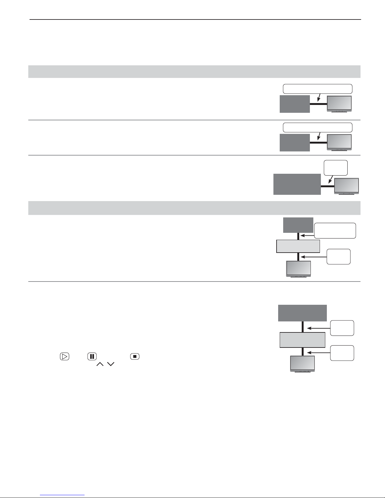
Source device connected directly to the TV
Remote Control Programming with Any Connection Type
Program the remote control to operate the A/V device. To control the device, set
the slide switch to the correct position for the device type. See Appendix C , “ Programming the Remote Control .” In the case of an A/V receiver, use the Audio Lock
Any Connection Type
A/V
Device
feature, page 70 .
NetCommand Control with Any Connection Type
Any Connection Type
Set up Net Command IR control of the device’s keys as desired. See “IR Emitter
Placement,” page 55 , and “Initial NetCommand Setup for Most Devices,” page 56 .
A/V
Device
C EC-Enabled HDMI Device with HDMI Connection Only
Turn on the TV’s NetCommand for HDMI feature. See the instructions in Appen-1.
dix E , “NetCommand HDMI Control of CEC Devices,” page 80 .
Experiment with the TV’s remote control (slide switch set to 2.
TV
which device functions it can operate.
) to determine
CEC-Enabled
A/V Device
Source device connected to an A/V receiver connected to the TV
A/V Receiver with HDMI Output (no CEC)
Assign the device to an A/V receiver input to allow you to set up Net Command 1.
IR control of the A/V receiver’s keys as desired. See “IR Emitter Placement,”
page 55 , and “Setting Up NetCommand Control of an A/V Receiver,” page 60 .
Set up Net Command IR control of the 2. source device’s keys as desired. See
“Initial NetCommand Setup for Most Devices,” page 56 .
Source
Device
A/V Receiver
TV
TV
TV
HDMI
Cable
TV
Any Con-
nection Type
HDMI
Cable
CEC-Enabled HDMI A/V Receiver
Turn on the TV’s NetCommand for HDMI feature. See the instructions in Appen-1.
dix E , “NetCommand HDMI Control of CEC Devices,” page 80 .
Try using the TV’s remote control to operate the A/V receiver’s volume and mute 2.
functions.
If the source device you want to connect also has CEC capability, see Appendix 3.
E for setup.
Try using the TV’s remote control to determine which device functions it can 4.
operate. For example, on a CEC-enabled DVD player, check for a response
to the
response to
(
PLAY
), (
CH/PAGE
PAUSE
/ .
), and (
STOP
) keys. For a cable box, check for a
CEC-Enabled
Source Device
HDMI
Cable
A/V Receiver
HDMI
Cable
TV
18 2. TV Setup
O
S
A
L
R
DVI/PC
INPUT3
INPUT2
INPUT1
L
R
U
OUTPUT
P
b
/ VIDE
O
A
D
T
AL
A
UDIO
OUTPUT
/
3
C
S
O
AUDIO
L
I
INPUT2
U
INPUT1
L
AVRA
UDIO OUTPU
R
b
Y Y
/ VIDE
O
P
r
A
A
I
A
UDIO
/
/
Using the TV with a Pe rsonal Computer
Connecting a Computer to the TV
Use one of the connection methods listed below based
on your computer’s video output.
Computer
Video Output
Video Connection
Digital DVI DVI-to-HDMI cable
or an HDMI cable
with an HDMI-toDVI adapter
Note: If the computer’s audio output
is a single mini jack, a mini audio-toRCA-male “Y” adapter cable is also
required.
HDMI HDMI-to-HDMI
cable
IMPORTANT
This TV accepts digital computer signals only.
Audio
Connection
Stereo audio
cables
No additional
audio connection is required.
Computer with
DVI and stereo
audio outputs
2.
3.
3.
2.
TV main
DVI/PC
L
AUDIO
R
panel
HDMI
HDMI
NetCommand
NetCommand
IR-
-
Output / External
utput / External
Controller Input
Controller Input
INPUT3
VIDEO
VIDEO
L
AUDIO
UDIO
R
DVI/PC
DVI/PC
L
L
AUDIO
AUDIO
AUDIO
R
R
L
ANT2/AUX
ANT2/AUX
AVR AUDIO
OUTPUT
4
3
2
1
DIO
Y
Y / VIDEO
INPUT2 INPUT1
R
NT1/MAIN
ANT1/MAIN
S-VIDEO
-VIDEO
Pr
Pb
L
AUDIO
AUDIO
R
DIGITAL
IGI
AUDIO
OUTPUT
) i 0 8 0 1 / p 0 2 7 / p 0 8 4 / i 0 8 4 (
/
7
See the TV specifications in Appendix
1.
A to confirm
that your computer signal is compatible with the TV.
Connect the computer’s digital signal output to one
2.
of the TV’s
HDMI
jacks. See the connection dia-
grams for the method suited to your equipment.
Connect the computer’s audio output using one of
3.
these options:
• For digital DVI signals, connect analog left/right
audio to the TV’s
DVI PC AUDIO INPUT
jacks.
• For HDMI signals, no additional audio connection is required.
Power on the TV and computer. The TV will detect
4.
the connection and display the Auto Input Sensing
screen.
In the
5.
Auto Input Sensing screen, press to
highlight PC in the list of device types. It is important to use the name PC so that the TV can process
the video signal correctly.
Press
6.
EXIT
to close the Auto Input Sensing screen.
Note: If your computer provides digital audio
output (coaxial or digital), you can connect it
directly to a digital A/V receiver and bypass
the TV.
A DVI connection from a personal computer requires
a separate audio connection. Computer connected to
the TV main panel (above).
Computer with
HDMI audio/video
output
2.
2.
HDMI
HDMI
4
4
3
3
2
2
1
1
NetCommand
NetCommand
IR-
-
S-VIDEO
-VIDEO
Output / External
Output / External
Controller Input
ontroller Input
INPUT3
NPUT3
Pr
VIDEO
VIDE
Pb
L
AUDIO
R
Y
Y / VIDEO
DVI/PC
DVI/PC
L
AUDIO
AUDIO
AUDIO
AUDIO
R
INPUT2 INPUT1
DIGITAL
DIG
AUDIO
OUTPUT
OUTPUT
L
R
AVR AUDIO
OUTPUT
T
ANT2/AUX
NT2/AUX
NT1/MAIN
ANT1/MAIN
TV main panel
) i 0 8 0 1 / p 0 2 7 / p 0 8 4 / i 0 8 4 (
1
2
L
R
An HDMI-to-HDMI connection carries all video and
audio on a single cable.
2. TV Setup 19
Using the TV with a Personal Computer
Co mputer Video Adjustments
Power on the computer if it is not already on.
1.
Select
2.
this, press
move the highlight to the PC icon, and press
Working from the computer, change the resolution
3.
of the computer image. View the computer image
on the TV and maximize the computer resolution
while maintaining a suitable aspect ratio for the
image.
Perform TV video adjustments.
4.
VIDEO
adjustment options. The following
additional adjustments are available
for computer video:
Horiz Position (Horizontal Position).
Manually adjust the horizontal
position.
Vert Position (Vertical Position).
Manually adjust the vertical position.
Press
5.
picture format best suited to the
image. See the chart on this page
showing how different computer resolutions can be displayed on the TV.
PC from the Input Selection menu. To do
INPUT
to open the Input Selection menu,
Press
repeatedly to access video-
FORMAT
repeatedly to find the
Tip
Set the computer’s screen saver to display a pattern
after several minutes of inactivity. This acts as a
reminder that the TV is powered on.
ENTER.
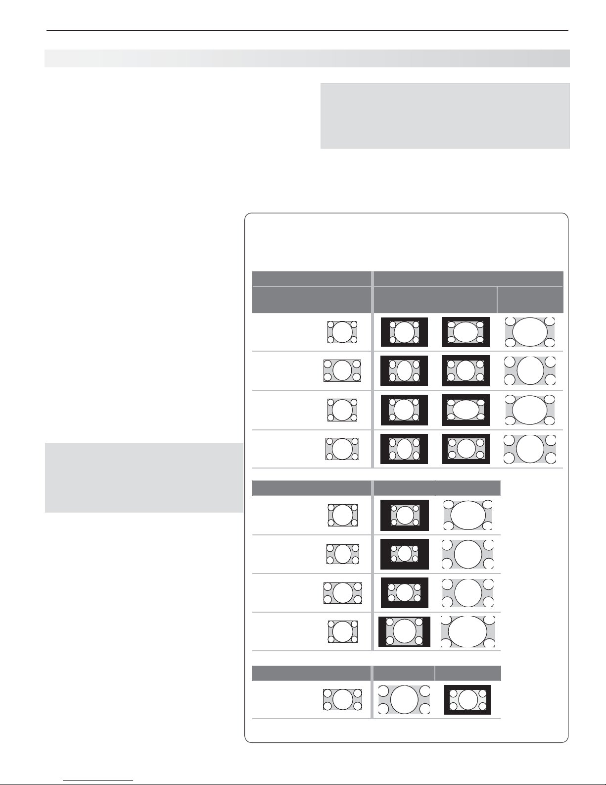
C omputer Display Formats
Press the
available for your computer’s video signal.
VGA
640 X 480
WVGA
848 X 480
SVGA
800 X 600
FORMAT
key repeatedly to cycle through the TV displays
Computer Signal
Original Format
As Displayed on TV Screen
4 X 3
Standard
16 X 9
Standard
Zoom
Distortion in Computer Images
Computer images may show distortion
when viewed on the TV, e.g., lines that
should be straight may appear slightly
curved.
Image Resolution
Your Mitsubishi TV can display resolutions
from standard VGA (640 x 480) through
1920 x 1080 signals at a refresh rate of
60 Hz. See Appendix A , “ Specifications ”
( page 66 ) for more on compatible screen
resolutions.
In most cases, the computer will select
the best resolution match to display on
the TV. You can override this setting if you
wish. Refer to your computer operating
system’s instructions for information on
changing the screen resolution.
You may need to restart the computer for
changes to take effect.
WSVGA
1064 X 600
Original Format Standard Zoom
XGA
1024 X 768
PC 720p
1280 X 720
WXGA
1360 X 768
SXGA
1280 X 1024
Original Format Standard Reduce
PC 1080p
1920 X 1080
20 2. TV Setup
HDMI
3
2
1
IR
Outp
C
t
S
O
V
O
AUDIO
R
A
O
C
3
INPUT2
INPUT1
R
UDIO
OUTPUT
A
O
L
PbY
Y
/ VIDE
O
P
N
DIG
A
U
O
/
/
/
Using a CableCARD
The CableCARD™ system allows your TV to receive,
decode, and unscramble the premium digital channels
included in your cable TV subscription without the use
of a cable box. The system is unidirectional, meaning
that certain digital cable services, such as requests
for video-on-demand and pay-per-view programs, a
cable operator’s enhanced program guide, and dataenhanced television services may require use of a
set-top box instead. For more information, call your
local cable operator.
Note: CableCARD requires the TV’s Fast Power On
setting. If you insert a CableCARD, the TV will
automatically override a Low Power setting and
change to the Fast Power On setting.
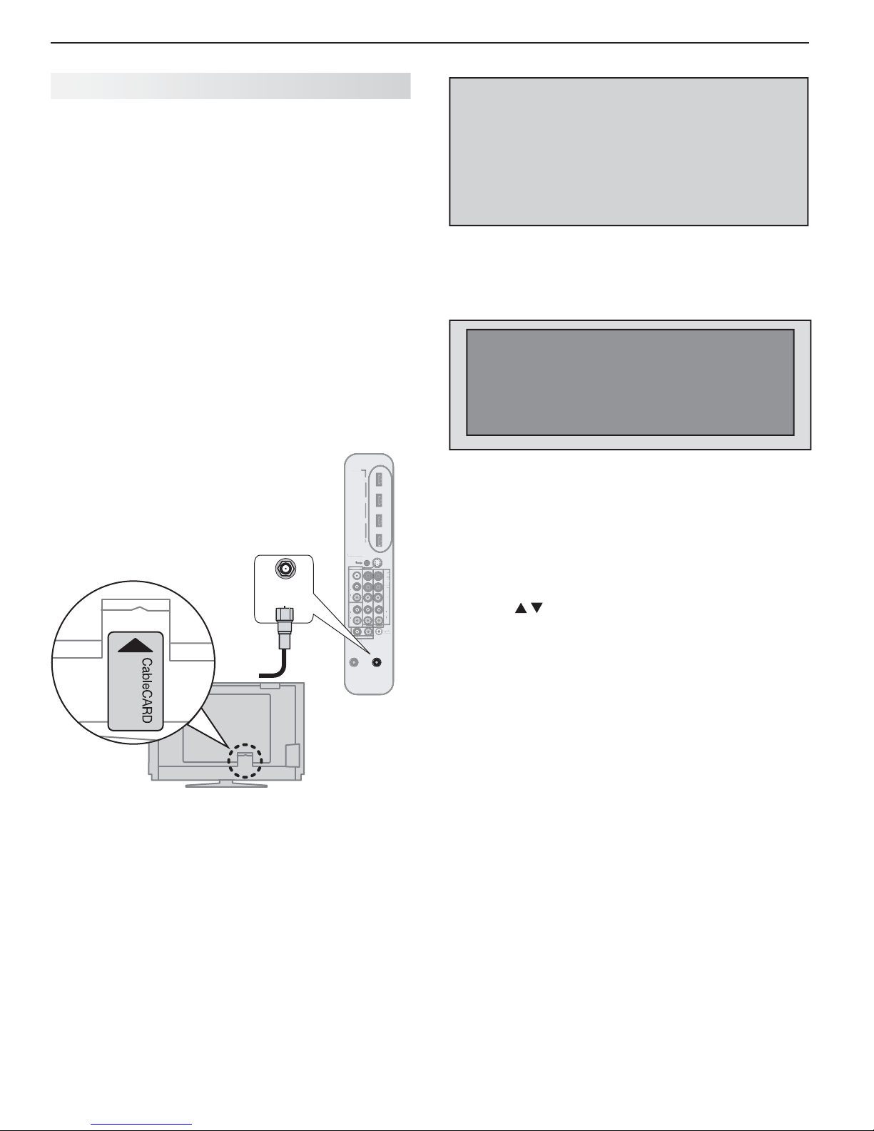
Installing a CableCARD
Connect your primary incoming cable to
1. ANT1/MAIN
on the back of the TV.
Power on the TV.
2.
Insert the CableCARD
3.
into the CableCARD
slot with the front of
the card oriented as
shown in the diagram
below
.
TV main panel
ANT1/MAIN
To ANT 1
HDMI
NetCommand
NetCommand
IR-
-
Output / External
ut / External
ontroller Inpu
Controller Input
INPUT3
INPUT
VIDEO
IDE
L
AUDIO
R
DVI/PC
DVI/P
L
AUDIO
UDI
R
ANT2/AUX
ANT2/AUX
4
3
2
1
S-VIDEO
-VIDE
)i0801 / p027 / p084 / i084(
Pr
r
Pb
Y
Y / VIDEO
L
AUDIO
UDI
R
INPUT2 INPUT1
DIGITAL
I
DIO
AUDIO
OUTPUT
UTPUT
L
R
AVR AUDIO
OUTPUT
ANT1/MAIN
ANT1/MAI
In order to start cable
service for this device, please contact
your cable provider
1-800-xxx-xxxx
CableCARD(tm): xxx-xxx-xxx-xxx-xxx-x
Host: xxx-xxx-xxx-xxx-x
Data: xxx-xxx-xxx-xx
UnitAddress: xx-xxxxx-xxxxx-xxx
Press EXIT to exit.
Sample CableCARD information screen. Write down
the information before contacting your cable provider.
CableCARD Menu
CableCARD menu
Network Setup
CableCARD(tm) Status
CableCARD(tm) Pairing
Conditional Access
Sample CableCARD menu
To display the CableCARD menu with links to applications from your cable provider:
While watching CableCARD, press
1.
INPUT
Input Selection menu.
With the CableCARD icon highlighted, press
2.
open the CableCARD menu.
Press
3.
to highlight a link, then press ENTER to
access the linked page.
To redisplay the
4.
CableCARD menu, repeat steps 1
and 2.
Press
5.
EXIT
to return to TV viewing.
If there are technical problems with the CableCARD, an
error screen automatically displays with information that
may be needed by your cable provider when you call
them for assistance.
to open the
MENU
to
Wait a few moments while the CableCARD initial-
4.
izes. A message will display on screen when initialization is complete.
Displaying CableCARD Information
To display information needed by your service provider
to start cable service, press
menu appears, press
9 9 9.
MENU
and when the Main
Moving Through Other CableCARD Screens
In addition to CableCARD menus, other CableCARD
application screens may display and require you to
make additional selections. When using these screens
on your Mitsubishi television:
Blue text denotes a function. Press •
ENTER
to perform
the function.
You cannot move backward through the links. To •
exit the CableCARD system, press
EXIT
. The
CANCEL
key may not work with some CableCARD screens.
Contact your cable provider if you have any problems
with the application screen displays.
TV Connections
3
Before You Begin
21
Auto Input Sensing
The TV’s Auto Input Sensing feature automatically recognizes most connections and prompts you to identify
the type of device connected. See page 14 for more on
Auto Input Sensing.
Connection Types
Review the connection types available on your input
devices and use connections that will give the best
video quality. For example, choose HDMI over component video, and choose component video over S-video
or composite video.
Picture Quality
For best picture quality, route signals directly from
the input device to the TV; avoid routing video signals
through an A/V receiver, for example.
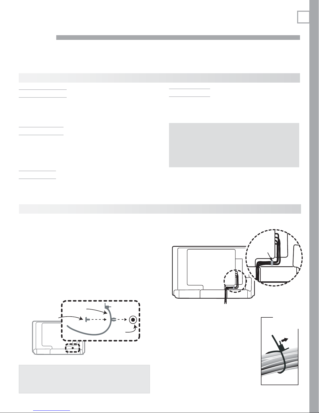
Cable Management
One cable tie with a locking pin is supplied with the accessories. Use the tie to keep cables organized and connected.
Surround Sound
For best surround sound audio quality, route audiosignal cables or HDMI cables from the source device
directly to your A/V receiver or sound system.
IMPORTANT
Accessory items such as cables, adapters,
splitters, or combiners required for TV
connections are not supplied with the TV.
These items are available at many electronics
stores.
Cable Routing
Installing the Cable Tie
Remove the locking pin from the cable tie and
1.
insert the anchor prongs into the hole on the back
of the TV.
Reinsert the pin in the cable tie to secure the tie to
2.
the TV.
$BCMFUJF
1JO
#BDLPG57
IMPORTANT
Be sure to leave enough cable slack below the cable tie
to allow the TV to swivel freely. Without enough slack,
there is a risk of damaging the cables and the TV.
)PMFJO
CBDLPG57
Cable tie
Unlatching the Cable Tie
Pry up the latch tab and push or pull
the free end of the tie through the
latch.
You may be able to lift the latch tab
by pinching the tab and latch body
between your thumb and index finger.
You may find it easier to pry up the
latch tab using a plastic wallet card or
similar object.
Cable routing on
back of TV
Pry up tab
to release
22 3. TV Connections
3
O
C
S
O
AUDIO
L
R
AUDIO
L
INPUT3
INPUT2
1
L
U
OUTPUT
O
L
b
Y Y
/ VIDE
O
A
GI
T
AL
O
T
/
/
H
4
2
I
O
C
S
V
O
A
R
INPUT2
UDIO
T
AUDIO
b
Y Y
/ VIDE
O
DIG
UDIO
T
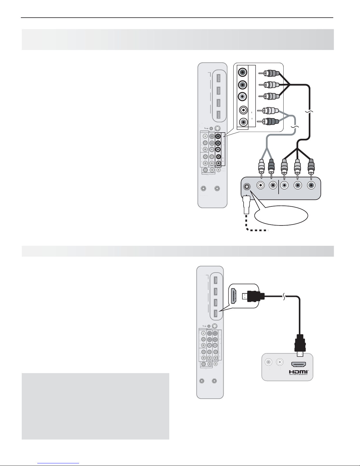
H DTV Cable Box or Satellite Receiver, DVD Player, or Other Device with
Co mponent Video
If your cable box or satellite receiver has an HDMI
output, use the connections for HDMI devices
described on this page .
Required: RCA component video cables, left/right
analog stereo audio cables.
Connect RCA-type cables from the
1. Y Pb Pr
on the device to the
Y Pb Pr
inputs on the TV main
outputs
panel, matching the colored green, blue, and red
connections.
Connect left (white) and right (red) audio cables
2.
from the device to
AUDIO L
and R on the TV main
panel.
Cable Box or Satellite Receiver Only:
3.
Connect
the cable from the outside cable or satellite service
to
CABLE IN
or
SATELLITE IN
on the cable box or
satellite receiver. See your device’s owner’s guide
for instructions and cable compatibility.
HDMI
NetCommand
NetCommand
IR-
-
Output / External
utput / External
ontroller Input
Controller Input
INPUT3
VIDEO
VIDEO
L
AUDIO
R
DVI/PC
DVI/PC
L
AUDIO
R
L
AVR AUDIO
OUTPUT
4
3
2
1
Y
Y / VIDEO
Y / VIDEO
INPUT1
INPUT
INPUT2 INPUT1
R
DIO
S-VIDEO
-VIDE
Pr
Pr
Pb
Pb
AUDIO
AUDI
AUDIO
DIGITAL
DI
AUDIO
AUDIO
OUTPUT
UTPU
) i 0 8 0 1 / p 0 2 7 / p 0 8 4 / i 0 8 4 (
) i 0 8 0 1 / p 0 2 7 / p 0 8 4 / i 0 8 4 (
0
8
0
L
L
R
R
TV
main
panel
Y / VIDEO
INPUT1
) i 0 8 0 1 / p 0 2 7 / p 0 8 4 / i 0 8 4 (
Pr
Pb
L
AUDIO
R
2.
2.
1.
1.
Note:
To hear digital surround sound, connect the digital
audio output from the device directly to your digital
ANT2/AUX
ANT2/AUX
NT1/MAIN
ANT1/MAIN
A/V receiver.
3.
Incoming from
Figure 1. Connecting a device with
component video outputs
H
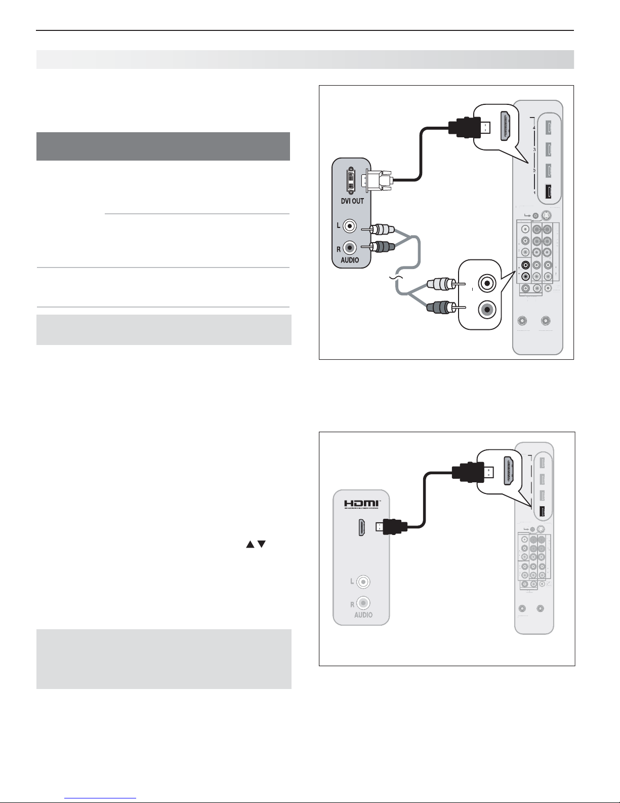
D MI Device (Cable Box, Satellite Receiver, DVD Player, or Other Device
Required: HDMI-to-HDMI cable.
Connect an HDMI cable from the TV main panel to the
HDMI device output. HDMI devices provide video and
audio through the single cable.
Mitsubishi recommends you use category 2 (highspeed) HDMI cables to connect HDMI 1.3 source
devices. High-speed category 2 cables bring you the
full benefits of Deep Color and x.v.Color. See “HDMI
Cable Categories,” page 10 , for more on HDMI cable
types.
IMPORTANT
HDMI and Audio Signals
Digital Surround Sound: The TV’s HDMI inputs
can receive digital stereo audio signals only. To
hear digital surround sound from an HDMI device,
connect the device’s HDMI or digital audio output
directly to your A/V receiver. See the Owner’s
Guides for those devices for instructions.
cable service or
satellite dish
HDMI
DMI
4
3
3
2
1
1
NetCommand
NetCommand
IR-
R-
Output / External
Controller Input
utput / External
ontroller Input
INPUT3
INPUT3
VIDEO
IDEO
L
AUDIO
AUDI
R
DVI/PC
DVI/PC
L
L
AUDIO
UDIO
R
L
AVR AUDIO
ANT2/AUX
ANT2/AUX
INPUT2 INPUT1
OUTPUT
OUTPU
Y
Y / VIDEO
R
R
ANT1/MAIN
ANT1/MAIN
S-VIDEO
INPUT1
-VIDEO
DIGITAL
AUDIO
OUTPUT
OUTPU
Pr
Pb
AUDIO
) i 0 8 0 1 / p 0 2 7 / p 0 8 4 / i 0 8 4 (
4
i
4
L
R
I
TV main
panel
Figure 2. Connecting an HDMI device.
L
R
AUDIO
CABLE IN or
SATELLITE IN
)
Any HDMI
device
R L
AUDIO
AUDIO
Pb Y Pr
3. TV Connections 23
3
I
Outp
C
S-VIDEO
AUDIO
R
3
INPUT2
UDIO
OUTPU
AUDIO
L
R
b
/ VIDE
O
P
r
A
DIG
A
UDIO
O
T
NetC
/
A
C
O
S
O
O
A
O
R
C
INPUT2
INPUT1
R
AVRA
UDIO
O
AUDIO
L
b
/ VIDE
O
P
r
A
A
GI
T
AL
A
NetC
/
/
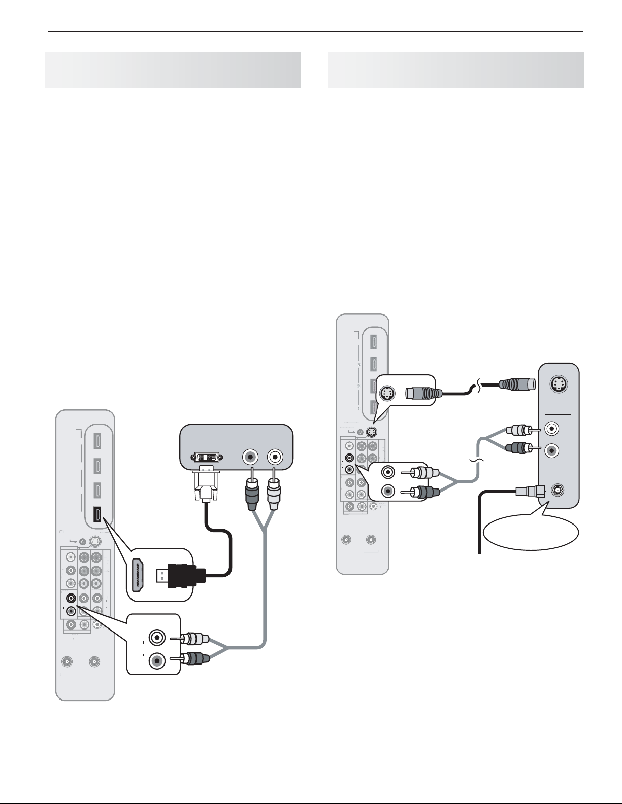
DVI Video Device ( Cable Box, Satellite
Receiver, DVD Player, or Other Device)
Standard Cable Box, Satellite Receiver,
or Other Device with S-V ideo
Connect DVI devices (digital only) to the TV’s HDMI
input jacks.
Analog stereo audio cables and a DVI-to-HDMI cable or
DVI/HDMI adapter and HDMI cable are required.
Connect the DVI-to-HDMI cable (recommended) or
1.
HDMI cable with DVI/HDMI adapter from the DVI
device’s back panel to the TV’s HDMI jack.
Note: If you are using a DVI/HDMI adapter, it is impor-
tant to connect the adapter to the DVI device for
best performance.
Connect a set of audio cables from
2. AUDIO OUT
on the DVI device back panel to the
AUDIO
on the TV main panel. Connect the red
DVI/PC INPUT
cable to the R jack and the white cable to the L
jack.
Note: The HDMI connection supports copy protection
(HDCP).
Some devices require connection to an analog input
first in order to view on-screen menus and to select DVI
as the ouput. Please review your equipment instructions for DVI connectivity and compatibility.
Digital DVI device
DVI OUT
AUDIO
R L
1.
1.
2.
2.
HDMI
NetCommand
ommand
IR-
R-
Output / External
ut / External
Controller Input
ontroller Input
INPUT3
INPUT
VIDEO
VIDEO
L
L
AUDIO
R
DVI/PC
DVI/P
DVI/PC
L
L
AUDIO
UDIO
AUDIO
R
R
L
AVR AUDIO
ANT2/AUX
ANT2/AUX
4
3
2
2
1
1
Y
INPUT2 INPUT1
R
OUTPUT
T
Y / VIDEO
INPUT1
NT1/MAIN
ANT1/MAIN
S-VIDEO
Pr
Pb
L
AUDIO
R
DIGITAL
AUDIO
OUTPUT
UTPU
TV
main
panel
) i 0 8 0 1 / p 0 2 7 / p 0 8 4 / i 0 8 4 (
I
DVI/PC
L
AUDIO
R
Required: S-Video cable and left/right analog stereo
audio cables.
Connect the cable from the outside cable or satel-
1.
lite service to
CABLE IN
or
SATELLITE IN
on the
cable box or satellite receiver.
Connect an S-Video cable from
2. S-VIDEO OUT
on
the cable box or satellite receiver back panel to
INPUT 3 S-VIDEO
Connect left (white) and right (red) audio cables
3.
from
AUDIO OUT
receiver to
on the TV main panel.
on the cable box or satellite
INPUT 3 AUDIO L
and R on the TV main
panel.
Note: Refer to the cable box or satellite receiver
Owner’s Guide for cable or dish antenna connections to the receiver.
HDMI
HDMI
4
TV main panel
Any S-Video
device
2.
S-VIDEO
2.
S-VIDEO
OUT
NetCommand
ommand
IR-
IR-
Output / External
utput / External
Controller Input
Controller Input
VIDEO
VIDE
L
L
AUDIO
AUDIO
AUDIO
R
R
R
DVI/PC
DVI/P
L
L
AUDIO
UDI
R
INPUT3
INPUT3
L
L
AVR AUDIO
OUTPUT
UTPUT
Y
Y / VIDEO
INPUT2 INPUT1
R
S-VIDEO
-VIDE
S-VIDEO
Connect audio
) i 0 8 0 1 / p 0 2 7 / p 0 8 4 / i 0 8 4 (
Pr
cables to INPUT
Pb
P
3 AUDIO
(
L
L
AUDIO
AUDIO
R
R
R
DIGITAL
DI
AUDIO
UDIO
OUTPUT
OUTPUT
3.
Incoming
cable from
ANT2/AUX
NT2/AUX
NT1/MAIN
ANT1/MAIN
wall
Figure 4. Connecting a device with S-Video
3.
AUDIO
1.
CABLE IN or
SATELLITE IN
L
R
Figure 3. Connecting a digital DVI device
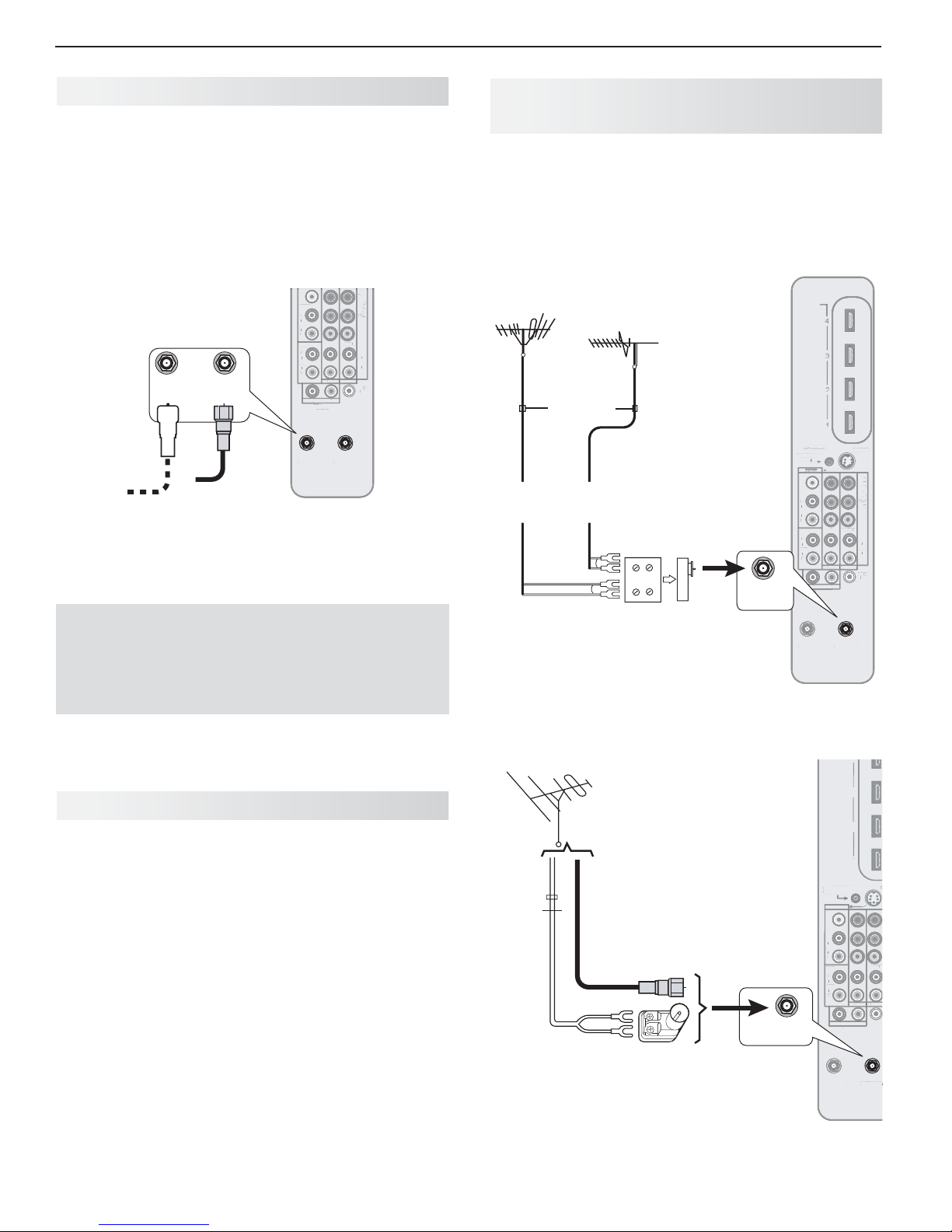
24 3. TV Connections
V
O
O
A
DVI/PC
INPUT2
INPUT1
L
A
VR
O
O
O
b
/ VIDE
O
A
I
T
AL
UDIO
O
IR
O
C
S
O
L
R
AUDIO
R
DVI/PC
INPUT2
A
VR
A
U
OUTPU
AUDIO
b
Y Y
/ VIDE
O
P
r
DIG
OUTPU
/
/
4
N
4
3
O
C
V
O
A
O
L
R
O
DVI/PC
L
INPUT2
INPU
R
U
OUTPUT
Y
/ VIDE
O
A
N
NetCommand
Wall Outlet Cable (no cable box)
(can be used with a CableCARD™)
It is very important to connect the incoming cable for
your primary viewing source to
Connect the primary incoming coaxial lead cable to
1.
ANT 1
on the TV main panel.
For an optional secondary antenna source, connect
2.
an antenna (or cable) to
ANT2/AUX
ANT1/MAIN
To ANT 1
To ANT 2
Figure 5. Wall Outlet Cable
Mitsubishi strongly recommends you avoid using
antennas with flat twin leads. Flat twin lead
antenna wires are subject to interference which
may adversely affect the performance of the TV.
We recommend using coaxial antenna cable.
ANT 1
.
ANT 2
.
VIDEO
IDE
L
AUDIO
AUDI
R
DVI/PC
L
AUDIO
UDIO
R
L
AVR AUDIO
OUTPUT
UTPUT
ANT2/AUX
NT2/AUX
TV main panel
Y
INPUT2 INPUT1
R
AUDI
ANT1/MAIN
ANT1/MAIN
Y / VIDEO
Pr
Pb
AUDIO
AUDI
DIGITAL
DIG
AUDIO
OUTPUT
L
L
R
UTPUT
) i 0 8 0 1 / p 0 2 7 / p 0 8 4 / i 0 8 4 (
i
p
7
p
4
Antennas with Separate UHF and
VHF Leads
Required: UHF/VHF combiner
Connect the UHF and VHF antenna leads to the
1.
UHF/VHF combiner.
Push the combiner onto
2. ANT 1
panel.
VHF antenna
(channels 2–13)
Flat twin lead
External antenna
or cable
1.
Figure 6. Connecting separate UHF and VHF Antennas
UHF antenna
(channels 14–69)
Side
Back
view
view
UHF
VHF
300-ohm-to75ohm combiner
on the TV main
HDMI
TV
IR-
-
Output / External
utput / External
ontroller Input
main
Controller Input
panel
VIDEO
VIDEO
L
AUDI
AUDIO
R
DVI/PC
L
L
AUDIO
R
2.
ANT1/MAIN
ANT2/AUX
ANT2/AUX
L
AVR AUDIO
OUTPUT
Y
Y / VIDEO
INPUT2 INPUT1
INPUT1
R
R
DIO
T
ANT1/MAIN
ANT1/MAIN
S-VIDEO
-VIDEO
Pr
Pb
P
AUDIO
DIGITAL
AUDIO
AUDIO
OUTPUT
) i 0 8 0 1 / p 0 2 7 / p 0 8 4 / i 0 8 4 (
L
R
I
T
Antenna with a Single Lead
A.
For an antenna with flat twin leads
Required: 300-ohm-to-75-ohm transformer.
A1. For an antenna with flat twin leads, connect the
300-ohm twin leads to the 300-ohm-to-75-ohm
transformer.
A2. Push the 75-ohm side of the transformer onto
ANT 1
on the TV main panel.
B.
For cable or antenna with coaxial lead
Connect the coaxial lead directly to
TV main panel.
ANT 1
on the
3
NetCommand
IR-
-
Output / External
utput / External
Controller Input
ontroller Input
INPUT3
INPUT3
VIDEO
IDE
L
AUDIO
UDI
R
DVI/PC
L
AUDIO
AUDI
R
L
ANT2/AUX
NT2/AUX
AVR AUDIO
OUTPUT
2
1
1
Y
Y
INPUT2 INPUT1
R
DIO
ANT1/MAI
ANT1/MAI
Y / VIDEO
T1
TV main panel
75-ohm
coaxial
lead
300-ohm
flat twin
lead
B.
A2.
Optional 300-ohm-
A1.
to75-ohm matching
transformer
Figure 7. Connecting a Single Antenna Lead
ANT1/MAIN
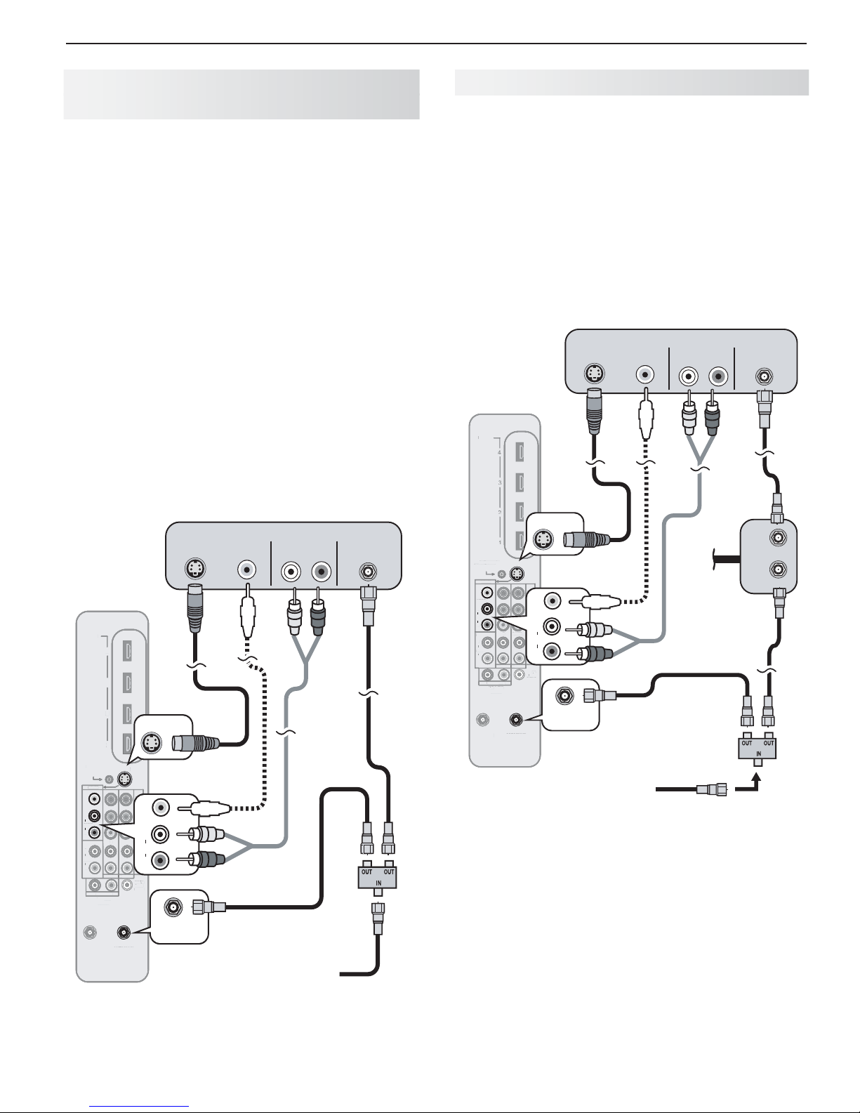
3. TV Connections 25
3
2
IR
O
C
S
V
O
I
INPUT2
I
1
UDIO
OUTPUT
O
P
b
Y
Y
/ VIDE
O
P
r
A
A
DIG
T
AL
A
UDIO
OUTPUT
/
/
/
AUDIO
R
DVI/PC
HDMI
I
Outp
S
O
V
R
INPUT2
INPUT1
L
U
OUTPU
AUDIO
R
P
b
Y
Y
/ VIDE
O
A
DIGI
T
AL
A
UDIO
OUTPUT
/
/
O
DVI/PC
L
VCR to an Antenna or
Wall Outlet Cable
Required: Two-way RF splitter, two coaxial cables, right
and left analog audio cables, either S-video or composite video cable.
Connect the incoming cable or antenna to
1. IN
RF splitter.
Connect one coaxial cable from
2. OUT
splitter to
Connect one coaxial cable from
3. OUT
splitter to
Connect either an S-Video or composite video
4.
cable from
VIDEO
ANTENNA IN
ANT 1
on the TV main panel.
VIDEO OUT
composite or
on the VCR back panel.
on the VCR back panel to a
S-VIDEO
jack on the TV main
on the RF
on the RF
panel. Connect only one type of video cable;
S-Video is recommended, if available.
To use the TV speakers with the VCR, connect left
5.
(white) and right (red) audio cables from
on the VCR to the associated
AUDIO L
on the TV main panel. If your VCR is mono (nonstereo), connect only the white (left) cable.
VCR
S-VIDEO
OUT
VIDEO
OUT
AUDIO OUT ANTENNA
L R
4.
HDMI
4
4
3
2
S-VIDEO
1
NetCommand
NetCommand
IR-
-
Output / External
utput / External
ontroller Input
Controller Input
INPUT3
VIDEO
IDEO
VIDEO
L
L
AUDI
AUDIO
AUDIO
R
R
DVI/PC
L
AUDIO
R
ANT2/AUX
NT2/AUX
NPUT3
L
AVR AUDIO
OUTPUT
S-VIDEO
S-VIDEO
Y
Y / VIDEO
INPUT2 INPUT1
NPUT
R
ANT1/MAIN
ANT1/MAIN
NT1/MAIN
-VIDEO
) i 0 8 0 1 / p 0 2 7 / p 0 8 4 / i 0 8 4 (
i
Pr
1
7
Pb
4
VIDEO
4
L
AUDIO
L
AUDIO
AUDI
R
R
DIGITAL
I
AUDIO
OUTPUT
ANT1/MAIN
TV main panel
4.
5.
3.
Incoming
Figure 8. Connecting a VCR to allow recording from an
antenna source.
5.
cable
on the
AUDIO OUT
and R jacks
IN
2.
2.
3.
1.
VCR to a Cable Box (Audio & Video)
Required: Two-way RF splitter, three coaxial cables,
right and left audio cables, S-Video or composite video
cable, plus video and audio cables required to connect
the TV to the cable box.
Connect the incoming cable to
1. IN
Connect one coaxial cable from
2. OUT
splitter to
Connect one coaxial cable from
3. OUT
splitter to
Connect one coaxial cable from
4. OUT
box to
HDMI
NetCommand
NetCommand
IR-
R-
Output / External
ut / External
Controller Input
Controller Input
INPUT3
INPUT3
VIDEO
IDEO
VIDEO
L
L
L
AUDIO
AUDIO
AUDIO
R
R
DVI/PC
L
AUDIO
AUDI
R
INPUT2 INPUT1
L
AVR AUDIO
DIO
OUTPUT
T
ANT2/AUX
NT2/AUX
Figure 9. Connecting a VCR to a cable box
Connect the cable box outputs to the TV as shown
5.
in one of the options listed below. This connection
allows the TV to receive the best available signal
directly from the cable box.
• Figure 1, page 22 : Component video output to
• Figure 2, page 22 : HDMI output to the TV’s
• Figure 4, page 23 : S-Video output to the TV’s
CABLE IN
ANT 1
on the TV main panel.
ANTENNA IN
S-VIDEO
OUT
VCR
TV
main
panel
S-VIDEO
S-VIDEO
-VIDE
S-VIDEO
i
) i 0 8 0 1 / p 0 2 7 / p 0 8 4 / i 0 8 4 (
Pr
2 7
Pb
4
VIDEO
i
4
L
Y
Y / VIDEO
AUDIO
L
L
AUDIO
R
R
DIGITAL
AUDIO
OUTPUT
R
ANT1/MAIN
ANT1/MAIN
ANT1/MAIN
the TV’s
6.
ANT1/MAIN
Y Pb Pr
the associated
HDMI
jack.
INPUT 3 S-VIDEO
the
INPUT 3 AUDIO
on the cable box.
on the VCR back panel.
VIDEO
6.
7.
3.
Incoming
cable
jacks; analog stereo audio to
AUDIO
jack; analog stereo audio to
jacks.
OUT
jacks.
on the RF splitter.
on the RF
on the RF
on the cable
AUDIO OUT ANTENNA
L R
Cable
box
5.
Audio and
video from
cable box
to TV
1.
7.
3.
IN
4.
4.
OUT
IN
2.
2.
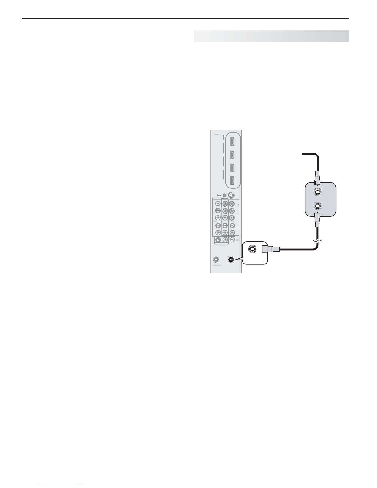
26 3. TV Connections
H
3
2
Outp
C
S
O
O
L
I
INPUT2
I
L
UDIO
O
AUDIO
L
Pb Y
Y
/ VIDE
O
A
GI
A
UDIO
O
/
/
D
Connect either an S-Video or composite video
6.
cable from
to a
VIDEO
main panel. Connect only one type of video cable.
S-Video is preferable to composite video, if available.
To use the TV speakers with the VCR, connect left
7.
(white) and right (red) audio cables from
on the VCR back panel to the associated
AUDIO L
is mono (non-stereo), connect only the white (left)
cable.
VIDEO OUT
composite or
on the VCR back panel
S-VIDEO
jack on the TV
AUDIO OUT
INPUT
and R on the TV main panel. If your VCR
Older Cable Box
Required: One coaxial cable.
Note: This connection is not recommended. The
other connections described in this chapter
provide better quality audio and video to the TV
and allow NetCommand to work with the cable
1. IN
2. OUT
box.
Connect the incoming cable to
Connect one coaxial cable from
box to
ANT 1
on the TV main panel.
on cable box.
on the cable
Note:
When using this connection confi guration with the
connections used in step 5, it is possible to view
live cable programs through the VCR Device. For
best picture quality always view live cable programs
directly from the TV input connected to the cable
box device.
HDMI
DMI
4
Incoming
cable
Cable
box
2.
NetCommand
NetCommand
IR-
IR-
Output / External
ut / External
ontroller Input
Controller Input
INPUT3
NPUT3
VIDEO
VIDE
L
AUDIO
AUDI
R
DVI/PC
VI/PC
L
AUDIO
AUDIO
R
L
ANT2/AUX
NT2/AUX
AVR AUDIO
UTPUT
OUTPUT
3
2
1
Y
Y / VIDEO
NPUT1
INPUT2 INPUT1
R
ANT1/MAIN
ANT1/MAIN
ANT1/MAIN
S-VIDEO
-VIDEO
) i 0 8 0 1 / p 0 2 7 / p 0 8 4 / i 0 8 4 (
0
Pr
1
0 2
Pb
TV main panel
L
AUDIO
R
R
DIGITAL
DI
AUDIO
OUTPUT
UTPUT
ANT1/MAIN
Figure 10. Connecting an older cable box
1.
IN
OUT
2.
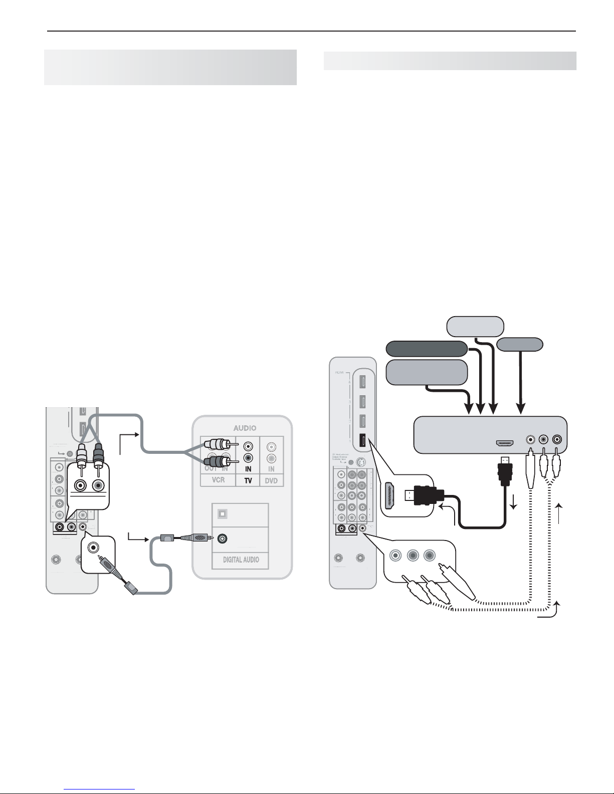
3. TV Connections 27
2
2
O
C
S
O
3
INPUT2
L
R
O
R
b
Y
/ VIDE
O
P
r
DIGI
T
AL
O
O
/
/
A
R
DVI/PC
L
CO
S-VIDEO
O
AUDIO
3
INPUT2
1
A
VR
A
UDIO
OUTPU
b
/ VIDE
O
A
T
AL
O
OUTPUT
/
D
L
A/ V Receiver (Sound System) Using
the TV’s Audio Output
Most setups require either a digital audio cable or
analog stereo audio cables. To send audio from TV
channels received on
nected directly to the TV, you must use one of the connections shown below.
The TV makes all audio available in digital and analog
formats:
Analog audio coming into the TV is output in digital •
stereo format on the
Digital incoming audio is output on the analog •
AUDIO OUTPUT L
Usually, only one of the following audio connections is
required.
To connect an analog A/V receiver•
Connect left (white) and right (red) audio cables
from
AVR AUDIO OUTPUT L
panel to the
To connect a digital A/V receiver with • Dolby
Digital surround sound and PCM audio support:
Connect one end of the digital audio cable to
DIGITAL AUDIO OUTPUT
Connect the other end to the
INPUT
on the back of the A/V receiver.
ANT 1, ANT 2
DIGITAL AUDIO OUTPUT
and R jacks.
and R on the TV main
TV AUDIO INPUT
on the back of the TV.
, or devices con-
jack.
AVR
on the A/V receiver.
COAXIAL DIGITAL
A/ V Receiver with HDMI Output
Required: One HDMI-to-HDMI cable
This option allows you to view content from devices
connected to an A/V receiver. The A/V receiver can
send audio and video to the TV over a single HDMI
cable. You can use an HDMI connection as described
here in addition to an audio connection from the TV’s
audio output.
You may be able to use the TV’s remote control (with
slide switch set to
enabled HDMI devices. Experiment with your equipment to determine which functions are available to the
TV’s remote control. See Appendix E , page 80 .
This setup allows you to use NetCommand-controlled
audio and video switching over the HDMI cable. See
“A/V Receiver Control: Automatic Audio and Video
Switching via HDMI” on page 63 .
TV main
panel
TV
) to operate connected CEC-
Cable box
DVD player
High-definition
DVD player
VCR
1
NetCommand
NetCommand
IR-
-
Output / External
utput / External
ontroller Input
Controller Input
VIDEO
VIDEO
L
L
AUDIO
AUDIO
R
DVI/PC
L
AUDIO
UDIO
R
ANT2/AUX
ANT2/AUX
INPUT3
INPUT
L
L
AVR AUDIO
AVR AUDIO
OUTPUT
OUTPUT
UTPUT
UDIO
L
Y
Y / VIDEO
Y
AVR AUDIO
OUTPUT
INPUT2 INPUT1
INPUT1
R
R
ANT1/MAIN
ANT1/MAIN
S-VIDEO
-VIDE
i0 80
Stereo analog cables
) i 0 8 0 1 / p 0 2 7 / p 0 8 4 / i 0 8 4 (
Pr
Pb
L
AUDIO
AUDIO
R
DIGITAL
DIGITAL
AUDIO
AUDIO
UDI
OUTPUT
UTPUT
OUTPUT
7
0
(for connecting an
analog A/V receiver)
R
Digital coaxial cable
(for connecting a
digital A/V receiver)
DIGITAL
AUDIO
OUTPUT
A/V receiver back panel
Figure 11. Connecting the TV to an A/V receiver
Note:
On rare occasions, an HDMI signal may be copy-•
restricted and cannot be output from the TV as a
digital signal. To hear these copy-protected signals
through the A/V receiver, use the connection for an
analog A/V receiver.
Check the A/V receiver’s Owner’s Guide for infor-•
mation concerning use of the digital input and
switching between digital sound and analog stereo
sound from the TV.
OPTICAL
OPTICAL
INPUT
COAXIAL
AXIAL
COAXIAL
INPUT
INPUT
INPUT
A/V receiver with
HDMI OUT
HDMI output
S-VIDEO
INPUT3
INPUT
VIDEO
VIDE
L
AUDIO
R
DVI/PC
VI/PC
L
AUDIO
AUDIO
R
L
L
L
ANT2/AUX
ANT2/AUX
AVR AUDIO
AVR AUDIO
OUTPUT
OUTPUT
Y
Y / VIDEO
INPUT
INPUT2 INPUT1
R
R
R
T
ANT1/MAIN
NT1/MAIN
Pr
Pr
Pb
AUDIO
AUDIO
DIGITAL
DIGI
DIGITAL
AUDIO
AUDIO
AUDI
OUTPUT
OUTPUT
) i 0 8 0 1 / p 0 2 7 / p 0 8 4 / i 0 8 4 (
L
R
HDMI
cable
(Video to TV)
DIGITAL
AUDIO
L
AVR AUDIO
OUTPUT
OUTPUT
R
Optional
analog or
digital audio
connection
Audio from TV to A/V Receiver
Figure 12. An A/V receiver connected to the TV with an
HDMI cable may offer special control capabilities.
To hear sound from devices connected to the TV only,
use the optional audio connection to send audio from
the devices through the TV to the A/V receiver..
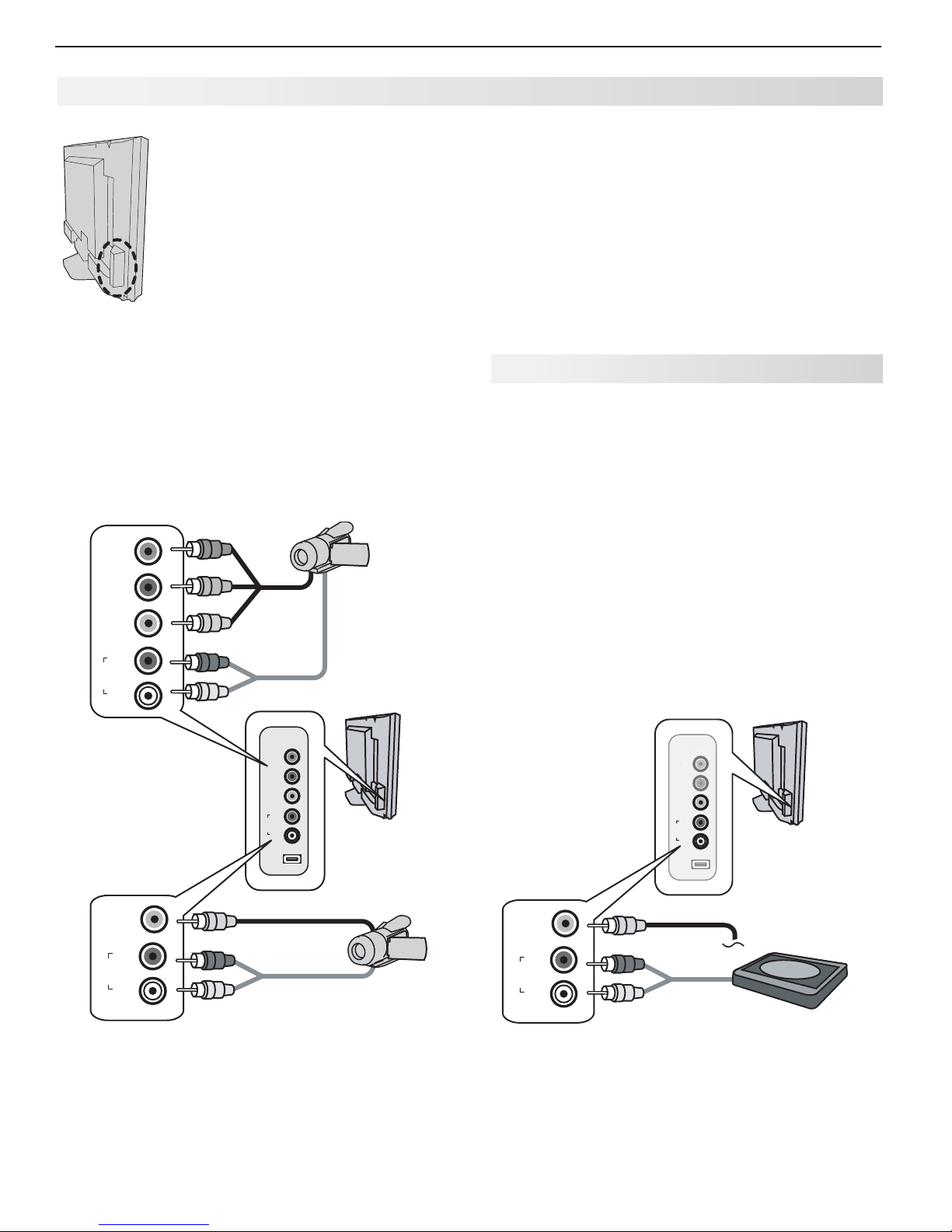
28 3. TV Connections
LL
USB US
R R
Y/Y/
V
Pb Pb
AA
INPUINPU
Camcorder
Convenience input jacks on the TV’s
side panel offer the easiest way to
connect a camcorder. Two different
connection options are described on
this page. You can alternatively use
any of the jacks on the main connection
panel.
Use jacks on the TV’s side panel
to connect a camcorder
A: Y Pb Pr Component Video Connection
Required: Component video and analog stereo audio
cables supplied with the camcorder.
Connect component video cables from
1. VIDEO OUT
on the camcorder to the TV’s
convenience jacks.
Connect left (white) and right (red) audio cables
2.
from
AUDIO OUT
R
on the TV.
Pr
Pb
Y/
VIDEO
R
O I D U A
L
on the camcorder to
VIDEO
VIDEO
O I D U A
O I D U A
USB
USB
1.
2.
INPUT 4
INPUT 4
Pr
Pr
Pb
Pb
Y/
Y/
R
R
L
L
Y Pb Pr
component
AUDIO L
A: Component
video plus
audio
TV back
TV convenience
panel
and
B: Composite Video Connection
Required: Composite video and analog stereo audio
cables supplied with the camcorder.
Connect the composite video cable from
1. VIDEO
OUT
on the camcorder to
VIDEO/Y
on the front of
the TV.
Connect left (white) and right (red) audio cables
2.
from
AUDIO OUT
R
on the front of the TV.
on the camcorder to
AUDIO L
and
A udio-Only Device
If you wish to connect an audio-only device to the TV, such
as an audio CD player or an MP3 player, follow these instructions.
Insert an unused RCA-style connector into the
1.
INPUT 4 VIDEO/Y
jack. The presence of this connector activates the TV’s Auto Input Sensing
feature.
When the
2.
Auto Input Sensing screen displays,
name the new input CD/Audio or MP3 Player.
Connect left (white) and right (red) audio cables from
3.
AUDIO OUT on the device to AUDIO L and R on the TV.
Keep the connector in the
4. VIDEO/Y
jack while using
the audio-only device.
TV back
INPUT 4
INPUT 4
Pr
Pr
Pb
Pb
Y/
Y/
Y/
VIDEO
VIDEO
VIDEO
IDEO VIDEO
R
R
R
O I D U A
O I D U A
O I D U A
L
L
L
USB
USB
B
TV convenience
panel
Y/
VIDEO
R
O I D U A
L
2.
B: Composite video
plus audio
Figure 13. Two connection options for a camcorder.
1.
Y/
VIDEO
R
O I D U A
L
1.
2.
Audio-only device
Figure 14. First insert an unused RCA-type connector
into the
VIDEO/Y
jack on the TV side or main panel
before connecting audio cables.
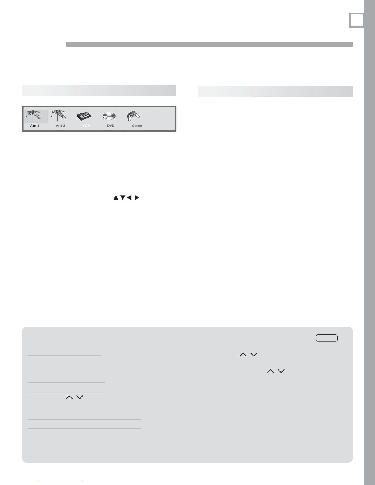
4
29
TV Operation and Features
Choosing a Vi ewing Source
Input Selection menu
Choose a viewing source from the Input Selection
menu. The current TV input appears as a full-color icon
in this menu.
Press
1.
2.
3.
More About the Input Selection Menu
• To assign meaningful names to the icons, see the
• To rearrange the icons, see the Inputs > Order
INPUT
to display the Input Selection menu. If
there are only two inputs to the TV,
between them without displaying the menu.
Highlight an input icon using
Press
ENTER
to switch to the input and close the
menu.
Inputs > Name menu, page 50 .
menu, page 50 .
INPUT
.
switches
Sleep Timer
The Sleep Timer turns the TV off after the length of time
you set. To set the TV to turn on at a certain time, see
the Setup > Timer menu on page 47 .
Setting the Sleep Timer
Press
1.
2.
3.
4.
Cancelling the Sleep Timer
1.
2.
Note: After fi ve seconds of inactivity, the message box
SLEEP
on the remote control.
Press
SLEEP
additional times to increase the time in
30-minute increments up to the maximum of 120
minutes.
Press
EXIT
or wait five seconds without pressing any
keys for the message to disappear.
Press
SLEEP
to view the time remaining before the
sleep timer turns off the TV.
Press
SLEEP
to display the on-screen message.
Press
SLEEP
repeatedly until OFF is displayed.
will disappear.
TV Tips
Turning the TV On or Off
To turn the TV on or off, point the remote control at the
front of the TV and press the
tively, press the
Controlling Sound Volume
Press •
See also • “Controlling A/V Receiver Sound Volume” on
page 16 .
Changing Channels (antenna sources)
To change channels:
Enter the channel number using the number keys •
on the remote control and press
POWER
button on the TV’s control panel.
VOL
/ to adjust the sound level.
POWER
button. Alterna-
ENTER
. For a two-
—
3
part digital channel, such as 3-1, press
to enter a dash (separator).
Press •
CH/PAGE
/ to change channels one
channel at a time.
Press and hold •
through channels.
Press •
QV
(QuickView) to switch back to the previ-
ously tuned channel.
Press •
GUIDE
highlight a channel, and press
Use the Fav (Favorites) feature to set up lists of •
favorite channels and tune to them with the
See Setup > Edit > Fav1–Fav6 on page 45 .
NOTE: Perform channel memorization to make fi nding
channels easier. See Setup > Scan, page 44 .
CH/PAGE
/ to move quickly
to display ChannelView channel listings,
ENTER
.
CANCEL
FAV
key.
1
 Loading...