

Page 1
MODEL
L75-A96
SUPPLEMENTAL OWNER’S GUIDE
For questions:
- Visit our website at www.mitsubishi-tv.com.
- E-mail us at TVsupport@mevsa.com.
- Call Consumer Relations at 1 (877) 675-2224 for operational or connection assistance.
• For information on System Reset, please see the back cover.
• To order replacement or additional remote controls, visit our website at www.mitsuparts.com or call
800-553-7278.
®
Page 2
2
CAUTION
RISK OF ELECTRIC SHOCK
DO NOT OPEN
CAUTION: TO REDUCE THE RISK OF ELECTRIC
SHOCK, DO NOT REMOVE COVER (OR BACK).
NO USER SERVICEABLE PARTS INSIDE. REFER
SERVICING TO QUALIFIED SERVICE PERSONNEL.
The lightning flash with arrowhead symbol within
an equilateral triangle is intended to alert the
user of the presence of uninsulated “dangerous voltage” within the product’s enclosure that may be of
sufficient magnitude to constitute a risk of electric shock to
persons.
The exclamation point within an equilateral
triangle is intended to alert the user to the
presence of important operating and maintenance (servicing) instructions in the literature accompanying the product.
MAINS DISCONNECTION: The mains plug is used
as the disconnect device. The mains plug shall remain
readily operable.
WARNING: This product contains chemicals known
to the State of California to cause cancer and/or birth
defects or other reproductive harm.
TV WEIGHT: This TV is heavy. Exercise extreme care
when lifting or moving it. Lift or move the TV with a
minimum of two adults. To prevent damage to the TV,
avoid jarring or moving it while it is turned on. Always
power off your TV, unplug the power cord, and disconnect all cables before moving it.
St and Requirement
Mitsubishi does not design, manufacture or sell matching
bases for the L75-A96 model television. When selecting
a stand, base, or other furniture to support the TV, please
make sure it is designed with the appropriate dimensions for stability and to support the TV’s weight plus the
weight of any additional equipment you plan to store.
Custom cabinet installation must allow for proper
air circulation around the television.
NOTE TO CATV SYSTEM INSTALLER: THIS REMINDER
IS PROVIDED TO CALL THE CATV SYSTEM INSTALLER’S
ATTENTION TO ARTICLE 820-40 OF THE NEC THAT PROVIDES
GUIDELINES FOR THE PROPER GROUNDING AND, IN PARTICULAR, SPECIFIES THAT THE CABLE GROUND SHALL BE CONNECTED TO THE GROUNDING SYSTEM OF THE BUILDING, AS
CLOSE TO THE POINT OF CABLE ENTRY AS PRACTICAL.
WARNING: To reduce the risk of fire or electric shock,
do not expose this apparatus to rain or moisture.
This apparatus shall not be exposed to dripping or
splashing and no objects filled with liquids, such as
vases, shall be placed on the apparatus.
En français
Cet appareil ne doit pas être exposé à des gouttes
ou à des éclaboussures et aucun objet rempli d’un
liquide, comme un vase, ne doit être placé sur
l’appareil.
FCC Declaration of Conformity
Product: Projection Television Receiver
Models: L75-A96
Responsible
Party:
Telephone: 1 (800) 332-2119
This device complies with Part 15 of the FCC Rules.
Operation is subject to the following two conditions:
(1) This device may not cause harmful interference, and
(2) This device must accept any interference received,
including interference that may cause undesired
operation.
Note: This equipment has been tested and found to
comply with the limits for a Class B digital device, pursuant to part 15 of the FCC Rules. These limits are designed
to provide reasonable protection against harmful interference in a residential installation. This equipment generates, uses and can radiate radio frequency energy and, if
not installed and used in accordance with the instructions,
may cause harmful interference to radio communications.
However, there is no guarantee that interference will not
occur in a particular installation. If this equipment does
cause harmful interference to radio or television reception, which can be determined by turning the equipment
off and on, the user is encouraged to try to correct the
interference by one or more of the following measures:
- Reorient or relocate the receiving antenna.
- Increase the separation between the equipment and
the receiver.
- Connect the equipment into an outlet on a circuit different from that to which the receiver is connected.
- Consult the dealer or an experienced radio/TV technician for help.
Changes or modifications not expressly approved by
Mitsubishi could cause harmful interference and would
void the user’s authority to operate this equipment.
Children and TV Viewing
The American Academy of Pediatrics discourages
media use by children younger than two years. For
more information, visit www.aap.org.
TV Software
• Do not attempt to update the software of this TV
with software not provided by or authorized by
Mitsubishi Electric Visual Solutions America, Inc.
Non-authorized software may damage the TV and
will not be covered by the warranty.
• Automatic software updates will be downloaded
over the internet to the TV if StreamTV is set up
and connected to the internet.
Note: Features and specifications described in this
owner’s guide are subject to change without notice.
Mitsubishi Electric Visual Solutions
America, Inc.
9351 Jeronimo Road
Irvine, CA 92618-1904
For assistance call 1(877) 675-2224
Page 3

3
Contents
Important Safety Instructions ................ 4
Laser Safety ............................. 5
1 Additional TV Features
Camera Images and Music Files
Using the TV with a Personal Computer ....... 10
Picture Shape and Display Formats .......... 12
Inputs and Outputs ...................... 13
2 TV Menus
Main Menu ............................ 15
Picture............................... 15
Sound ............................... 19
Captions ............................. 20
............................... 21
Setup
Inputs
............................... 24
Lock ................................ 26
3 HDMI Control of CEC Devices
Enabling HDMI Control of CEC Devices
HDMI Control of an HDMI A/V Receiver and
Connected Devices .................... 31
Resolving CEC Conflicts .................. 32
Removing an HDMI Device ................ 32
Using HDMI Control ..................... 32
............. 6
....... 30
Mitsubishi Electric Visual Solutions
America and the Environment
As part of its ongoing environmental efforts, Mitsubishi
Electric Visual Solutions America, Inc. (MEVSA) joined
the Electronic Manufacturers Recycling Management
Company’s (MRM) national recycling initiative. Your
MEVSA TV can be recycled at no charge to the consumer through MRM’s growing infrastructure of dropoff locations around the United States.
We encourage all of our customers to recycle their used
electronics. All waste computer monitors, portable
computers, digital picture frames, televisions, portable
DVD players, desktop printers, VCRs, and video game
consoles should be recycled.
For a listing of MRM recycling drop-off locations,
please visit www.MRMrecycling.com. MRM can also
be reached toll free at 1-888-769-0149
For more information about Maine’s electronic waste
law, please visit the Maine Department of Environmental
Protection website at www.maine.gov/dep/rwm/ewaste/
index.htm.
For other states please check your state or local government web sites for more information about local
laws and recycling options.
Appendices
Appendix A: TV Care .................... 33
Appendix B: Troubleshooting .............. 34
Trademark and License Information .......... 38
Warranty .............................. 47
Index ................................. 50
For assistance call 1(877) 675-2224
Page 4
4
Important Safety Instructions
Please read the following safeguards for your TV and
retain for future reference. Always follow all warnings
and instructions marked on the television.
1) Read these instructions.
2) Keep these instructions.
3) Heed all warnings.
4) Follow all instructions.
5) Do not use this apparatus near water.
6) Clean only with dry cloth.
7) Do not block any ventilation openings. Install in
accordance with the manufacturer’s instructions.
8) Do not install near any heat sources such as
radiators, heat registers, stoves, or other apparatus
(including amplifiers) that produce heat.
9) Do not defeat the safety purpose of the polarized
or grounding-type plug. A polarized plug has two
blades with one wider than the other. A grounding
type plug has two blades and a third grounding
prong. The wide blade or the third prong are
provided for your safety. If the provided plug does
not fit into your outlet, consult an electrician for
replacement of the obsolete outlet.
10) Protect the power cord from being walked on
or pinched particularly at plugs, convenience
receptacles, and the point where they exit from the
apparatus.
11) Only use attachments/accessories specified by the
manufacturer.
12) Use only with the cart,
stand, tripod, bracket,
or table specified
by the manufacturer,
or sold with the
apparatus. When
a cart is used, use
caution when moving
the cart/apparatus
combination to avoid
injury from tip-over.
13) Unplug this apparatus
during lightning storms or when unused for long
periods of time.
14) Refer all servicing to qualified service personnel.
Servicing is required when the apparatus has been
damaged in any way, such as power-supply cord or
plug is damaged, liquid has been spilled or objects
have fallen into the apparatus, the apparatus has
been exposed to rain or moisture, does not operate
normally, or has been dropped.
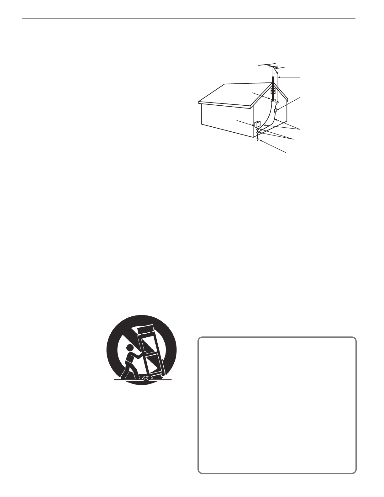
EXAMPLE OF ANTENNA GROUNDING
ANTE NNA
LEAD IN WIRE
GROUND CLAMP
ELECTRIC
SERVICE
EQUIPMENT
NEC — NATIONAL ELECTR ICAL CODE
ANTE NNA
DISCHAR GE UNIT
(NE C AR TIC LE 810-20)
GROUNDING
CONDUCTORS
(NEC ARTICLE 810-21)
GROUND CLAMPS
POWER SERVICE GROUNDING
ELECTRODE SYSTEM
(NE C AR T 250, P AR T H)
Outdoor Antenna Grounding
If an outside antenna or cable system is connected
to the TV, be sure the antenna or cable system is
grounded so as to provide some protection against
voltage surges and built-up static charges.
Replacement Parts
When replacement parts are required, be sure the
service technician has used replacement parts specified by the manufacturer or have the same characteristics as the original part. Unauthorized substitutions
may result in fire, electric shock or other hazards.
To avoid the risk of injury to the eyes and face, do not
look directly into the air vents while the television is
operating.
To avoid the risk of fire, do not use flammable solvents
(such as benzene or paint solvents) or flammable aerosols (such as polishes, cleaners, or insecticides) near
the television while it is operating or cooling.
ENERGY STAR
This is an ENERGY STAR® qualified TV. Products that earn ENERGY STAR reduce greenhouse
gas emissions by meeting strict energy efficiency
guidelines set by the U.S. Environmental Protection
Agency.
This TV uses power within ENERGY STAR guidelines
when the TV is in the default Home operations mode
(Welcome Screen > Home selection).
• Picture mode is set to Bright (Picture > Video
menu)
• Ambient Light Sensor is set to Minimum (Setup
> Energy menu)
The TV may exceed ENERGY STAR guidelines when
other picture modes are selected and/or when the
Ambient Light Sensor is set to Off.
®
For assistance call 1(877) 675-2224
Page 5
Laser Safety
Laser Safety
• This TV is in compliance with the requirements of IEC
60825-1 Ed. 2(2007).
• This TV is a CLASS 1 laser product. This TV poses
no risk to eyes or skin during normal use. An exposure hazard may exist only if the protective housing
is removed.
• This TV contains a CLASS 4 laser device, which by
itself may be hazardous. However, this TV incorporates a protective housing, optics and electronics
such that there should be no exposure to unsafe
levels of laser light during normal operation and
proper service.
• Do not open this product. No consumer controls
are inside. Only a trained LASERVUE® technician
should service this TV. Please call Mitsubishi for
assistance at
Safe Operation
• Always inspect the TV for damage after moving
it. If the cabinet or screen is physically damaged,
DO NOT connect the TV to an AC outlet.
1 (877) 675-2224 for assistance.
DO NOT power on the TV until it has been repaired
by qualified service personnel authorized by
Mitsubishi. See “Service and Customer Support”
page 34 .
• Caution. Use of controls or adjustments or performance of procedures other than those specified
herein may result in hazardous radiation exposure.
• Use external or remote controls to operate the
product. Connection to signal sources and power
are accomplished through the external connectors.
1 (877) 675-2224.
Call
5
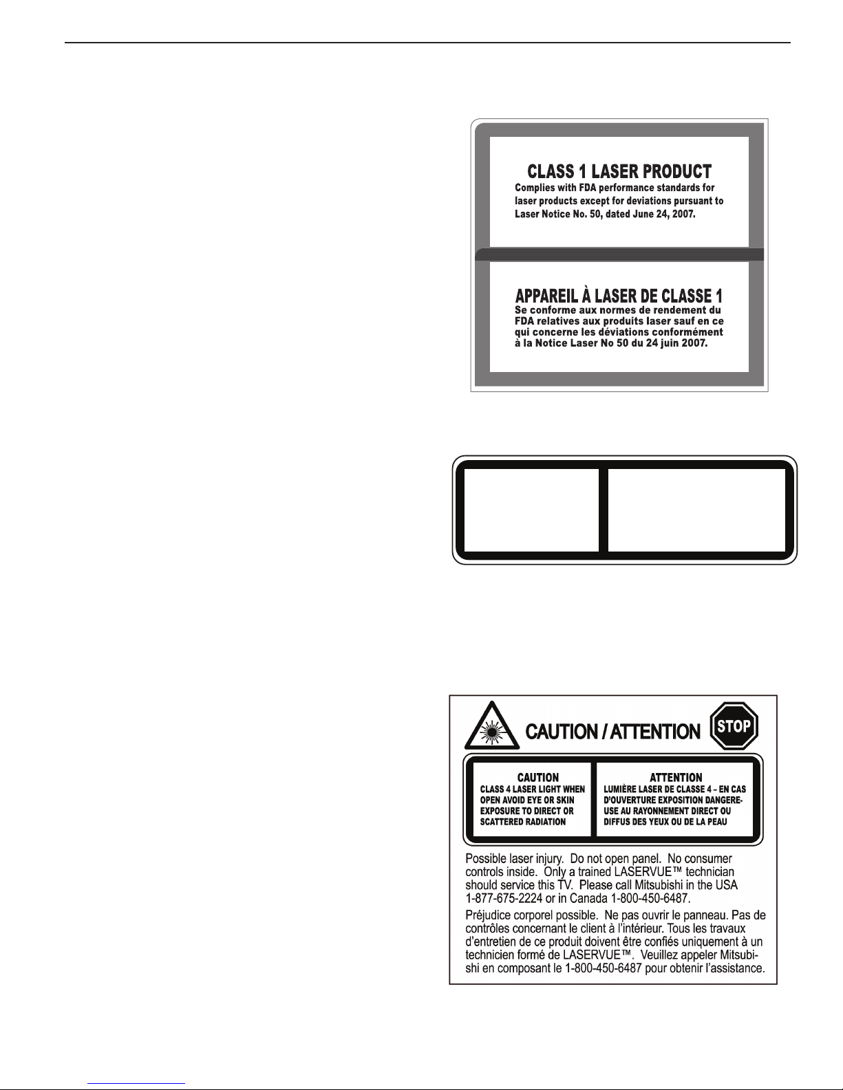
This label is located on the right lower back of the
television set.
CLASS 4 LASER LIGHT WHEN
CAUTION
OPEN AVOID EYE OR SKIN
EXPOSURE TO DIRECT OR
SCATTERED RADIAITON
LUMIÈRE LASER DE CLASSE 4 - EN CAS
D’OUVERTURE EXPOSITION DANGEREUSE AU RAYONNEMENT DIRECT OU
DIFFUS DES YEUX OU DE LA PEAU
This class-4 label and similar service warning labels
are located inside the back cover of the television in an
area that should not be accessed by the user under any
circumstances.
An additional class-4 label is located at the lower front
access panel under the front decorative bezel.
ATTENTION
Damage and Repair
• There are no user serviceable components in this
TV. Do not attempt to disassemble any part of the
TV.
• If damaged, the device must not be powered on or
used until it is repaired by qualified service personnel authorized by Mitsubishi. See “Service and
Customer Support” page 34 .
• Under no circumstances shall attempts be made to
operate this device without the screen in place or if
any portion of the enclosure, including the screen,
is cracked, broken, a liquid is spilled onto the TV or
is otherwise damaged.
This class-4 label is located at the center back of the TV
under the outer cover.
For assistance call 1(877) 675-2224
Page 6
6
Additional TV Features
1
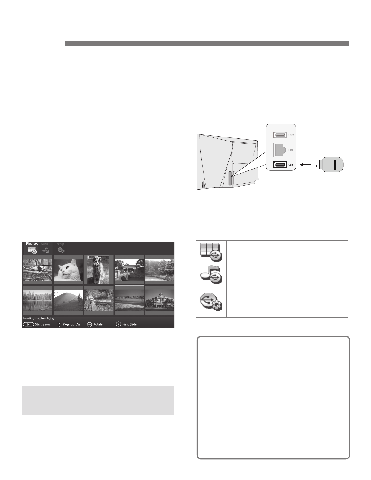
Camera Images and M usic Files
• The TV can read photo and music files from a
USB device. Photos must be in JPEG format and
music files must be in mp3 format. To play music
files while displaying a photo slide show, see “USB
Media Setup Menu” on the opposite page .
• The TV can display still images or motion video
from a camera through the
8 .
• To play music through the TV speakers from an
audio-only device, see “Using an Audio-Only
Device,” page 8 .
USB Source Devices
Y/VID EO
port. See page
2.
Connect your USB drive to the TV’s USB port.
The USB Media Player menu displays while files
are being read. Wait until icons appear in the menu
before continuing.
IMPORTANT
Do not use USBa for this purpose.
The TV is unable to read files from
the USBa port.
Use the lower USB port for photo or music files.
The USB Media Player Menu
USB Media menu, Photos option selected
Displaying the Menu
1.
Back up the data on your USB drive before connecting it to the TV. Mitsubishi is not responsible
for any file damage or data loss.
The TV can read JPEG files as created by the
camera. If you edit a picture file on a computer
and resave the image, the TV may be unable to
read the resaved file.
3.
When the USB Media Player icons display, highlight one of these choices and press
Photos
View photos or play a slide show
Audio
Listen to audio tracks or a playlist.
Setup
Perform setup for a slide show or playlist.
If music and image files are both present,
lets you play a slide show with music.
Picture Files Compatible with the USB Port
• Still images recorded on digital cameras using
the Exchangeable Image File Format, version
2.1 (EXIF 2.1) standard for digital still cameras
and Design Rules for Camera File Systems
version 1.0 (DCF 1.0)
• Some images opened and resaved on a computer may not play back or may not display
in the thumbnail list. This happens if the files
were resaved in an incompatible format.
ENTER
.
For assistance call 1(877) 675-2224
• Full path file names can be no longer than
50 characters and must end in a .jpg extension. Only the first 20 of the 50 characters will
display.
Page 7
1. Additional TV Features 7
Camera Images and Music Files, continued
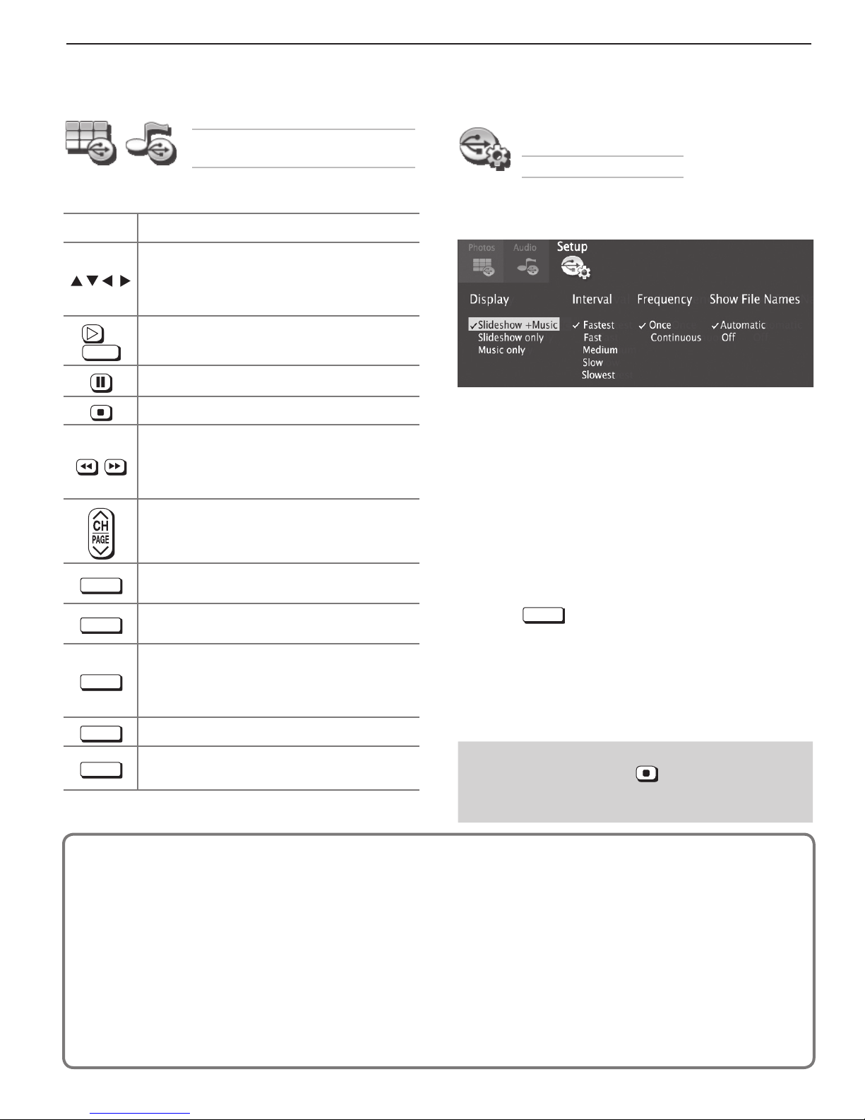
Using the Photos and Audio
Menus
U SB Media Setup Menu
Use these keys with your photo and audio files.
Key For Photos or Audio Tracks
• Moves the highlight left/right through
or
ENTER
GUIDE
INFO
EXIT
icons to select Photos, Audio, or
Setup.
• Moves the highlight from item to item.
Plays the slide show or playlist starting
from the highlighted item.
Pauses a slide show or playlist.
Stops a slide show or playlist.
• Highlights the first or last item on the
current page.
• Skips to the previous or next item
during play.
Displays the previous or next page of
items.
Rotates an image clockwise in 90˚ increments.
Displays the item name during play. Press
EXIT
to clear.
• Clears file information from the
screen.
• Moves the highlight to the top of the
Media menu.
Use the USB Media Setup menu to set up play of a
slide show or playlist.
• If JPEG image files and mp3 files are both on the
USB device, choose from:
- Slideshow + Music
- Slideshow only
- Music only
• Interval. Select the type of time interval for display
of each slide. The intervals may be longer for larger
files than for smaller ones.
• Frequency.
to play the complete slide show and/or playlist.
• Show File Names. Choose Automatic or Off.
• Press
and return to the USB Media Player menu.
Select the number of times (frequency)
EXIT
to close the USB Media Setup menu
MENU
INPUT
Notes on Using the USB Port
• The TV ignores all commands while reading files.
• Large files or high-capacity storage devices may
• The TV can read files up to 10 MB in size with a
• Use a USB drive instead of a card reader.
• Back up the data on your USB drive before con-
Displays the main menu; stops play.
Displays the
play.
take a long time to display.
maximum of 2,500 files stored on the device. The
FAT16 or FAT32 file system is recommended.
necting it to the TV. Mitsubishi is not responsible
for any file damage or data loss.
Input Selection menu; stops
IMPORTANT
Always stop playback with (STOP) or change to
a different TV input before disconnecting your USB
device.
Note:
Some manufacturers’ devices may be incompatible with the TV. If the TV is unable to display
your photos, you can:
• Transfer
• Use your digital camera’s composite
video output. See page 8 .
files to a different USB device.
For assistance call 1(877) 675-2224
Page 8
8 1. Additional TV Features
U
O
OU
UT
D
G
L
U
O
OU
UT
3D
G
SS
S
R
T
1
/
C
L
RLR
UT
e
a
p
t
P
b
P
r
L
R
/
E
O
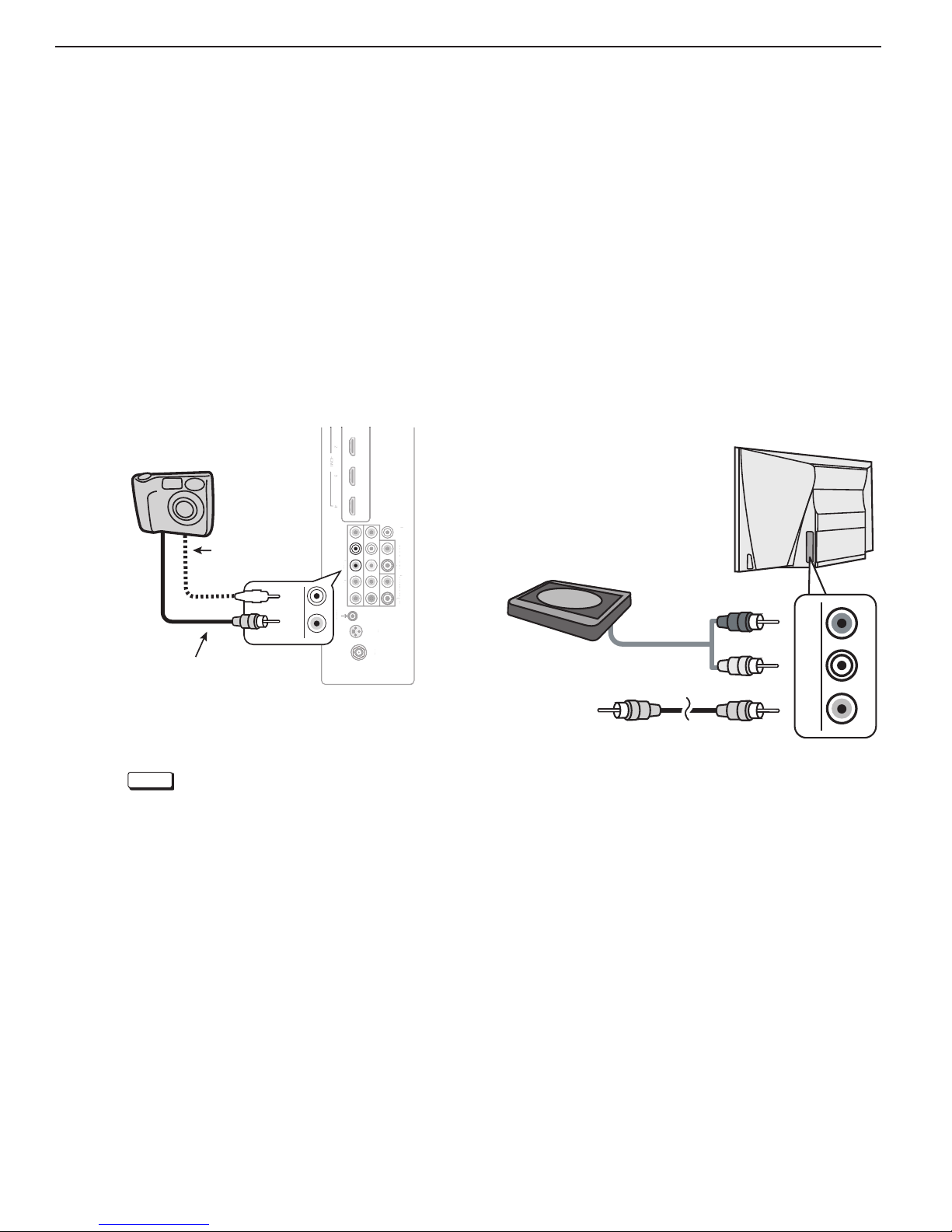
Camera Images and Music Files, continued
Phot os and Motion Video as Composite
Video
Connect the camera to the TV using a composite video
cable and control the slide show or movie through the
camera. The display resolution will be standard-definition (480i).
1.
Refer to the owner’s manual supplied with the
camera for instructions needed for this setup.
2.
Set the camera’s output signal type to NTSC and
put the camera into playback mode.
3.
With the camera still turned on, connect your digital
camera’s composite video cable (usually yellow) to
the TV’s
camera’s audio output cable to the
Camera connection using a composite video cable
Y/VID EO
Composite
video cable
jack. To hear audio, connect the
Optional audio
cable
L
Y/ VIDEO
TV
AUDIO L
IR-External
Controller Input
IR-Ext
Controller In
rn
l
u
jack.
OUTPUT
DIGITAL
A
AUDIO
I
TP
DI
ITA
DVI/PC
DVI
INPUT 2
INPUT 2INPUT
GLASSES
EMITTER
EMITTE
LA
E
ANT
AN
R
P
INPUT
INP
L
AVR AUDIO OUTPUT
AVR A
R
DI
TP
L
3D
LR
L
Y/ VIDEO
Y
Y/ VIDEO
VID
Pb Pr
INPUT 1
Using an A udio- Only Device
To use the TV speakers with an audio device such as an
MP3 or CD player with analog output,
1.
Insert an unused RCA-style connector into the
Y/VID EO
jack associated with the TV’s analog audio
input. The presence of this connector activates the
TV’s auto-detection.
2.
When the TV detects the
Y/VID EO
display the New Device Found screen. Name the
new input CD/Audio or MP3 Player.
3.
Connect left (white) and right (red) audio cables from
AUDIO OUT on the device to
on the TV.
4.
Keep the connector in the
VIDEO/Y
the audio-only device.
Audio-only
device
Unused
RCA-style plug
(plug in first)
follow these steps.
connector, it will
the
L and R audio inputs
jack while using
LR
Y/ VIDEO
4.
When the New Device Found screen displays,
assign the name Camcorder.
5.
Press
EXIT
to close the New Device Found
screen.
6.
If viewing photos, control the slideshow from the
camera. Advance through the images manually or
check if the camera can advance automatically.
For assistance call 1(877) 675-2224
Page 9
1. Additional TV Features 9
Camera Images and Music Files, continued
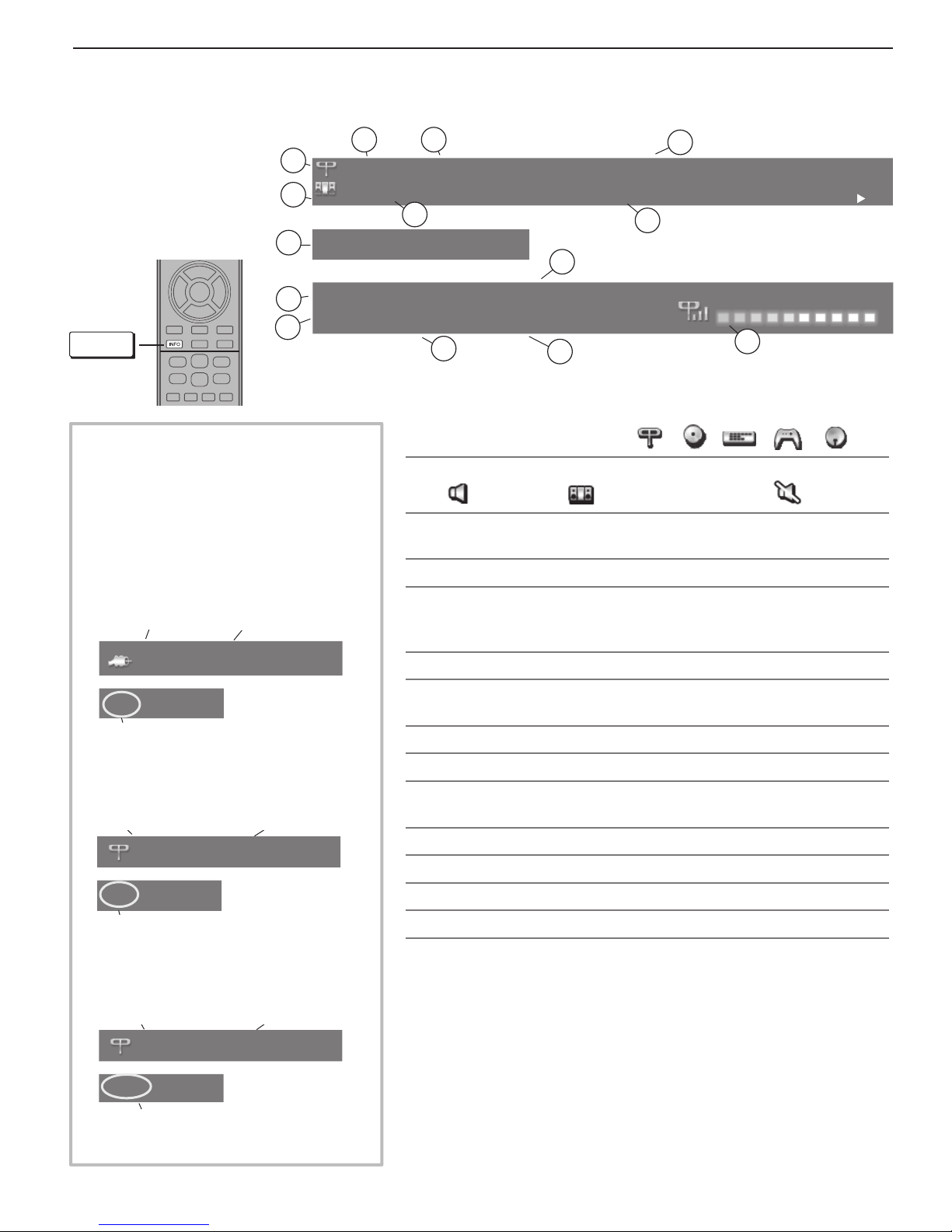
St atus Display
Press the
INFO
key to see
the on-screen status
display. The most
common displays are
shown here.
1
2
8
Sleep 30 min
Tuesday 9:10 PM
9
1080i Standard
10
INFO
About Channel Numbers
Channel Numbers for Over-the-Air
Reception or Reception by Direct
Cable
Note: All signals are automatically
converted to 1080p for display.
Standard-Definition Analog Channels
Cable Reception
Cable 3
Channel 3
3
4
6
402-101 KABC Monday Night Football
TV-PG DLSV
5
11
1.
Current Input. Examples:
2. Audio Indicator. Key:
3. Channel number (antenna source only)
Digital channel includes major and sub-channel numbers.
4. Digital channel name (if broadcast); antenna source only.
5. V-Chip rating
• Digital signal: Antenna source only
• Analog signal:
6. Program name (if broadcast); digital antenna source only
St. Louis vs. Tampa Bay, played in Tampa for
7
Sample information from the
13
on-screen status display
English
Surround
12
Antenna
DVD
TV speakers External sound system Mute
Antenna or
VIDEO
14
DVR
Game
composite jack
Sat. Rcvr.
480i Stretch
Receiving Standard-Definition
Analog Signal (480i)
Standard-Definition Digital Channels
Over-the-Air
Antenna
Reception
Main Channel 7
Sub-Channel 1
Ant 7-1 KABC-SD
480i Stretch
Receiving Standard-Definition
Digital Signal (SD)
High-Definition Digital Channels
Over-the-Air
Antenna
Reception
Main Channel 7
Sub-Channel 1
Ant 7-1 KABC-HD
1080i Standard
Receiving High-Definition
Digital Signal (HD)
7. Program description (if broadcast); digital source,
Press the
INFO
key additional times to see more of the description.
antenna only.
8. Sleep Timer remaining time
9. Day and time
10. Signal type being received. See “Signal Definitions” on this
page .
11. Screen format in use
12. Program audio indicator (antenna source only)
13. Available language (digital source, antenna only)
14. Signal-strength indicator (digital source, antenna only)
Sign al Definitions
480i: Standard-definition, older type interlaced signals from the
composite
VIDEO
, component
Y Pb Pr
, or
HDMI
jacks.
480p: Standard-definition progressive-scan signals on the
component
Y Pb Pr,
or
HDMI
jacks.
720p and 1080i: High-definition signals received through the
component
Y Pb Pr,
or
HDMI
jacks. These signals are always 16:9
(widescreen), but may contain embedded 4:3 images with sidebars.
1080p: High-definition signals from a PC, Blu-ray player, or some
satellite and set-top boxes; HDMI inputs only.
ANT
ANT
,
ANT,
,
For assistance call 1(877) 675-2224
Page 10
10 1. Additional TV Features
A
U
O
OU
UT
G
L
AU
O
OU
UT
3D
G
SS
S
E
R
T
INPUT 2
INPUT 1
/
C
LRL
R
UT
e
al
C
t
P
b
P
r
Y/
E
O
R
H
I
U
O
OU
UT
G
L
AU
O
OU
UT
3
G
SS
E
R
2
1
/
C
L
RLR
UT
IR
E
e
al
C
t
P
b
r
L
R
/
E
O
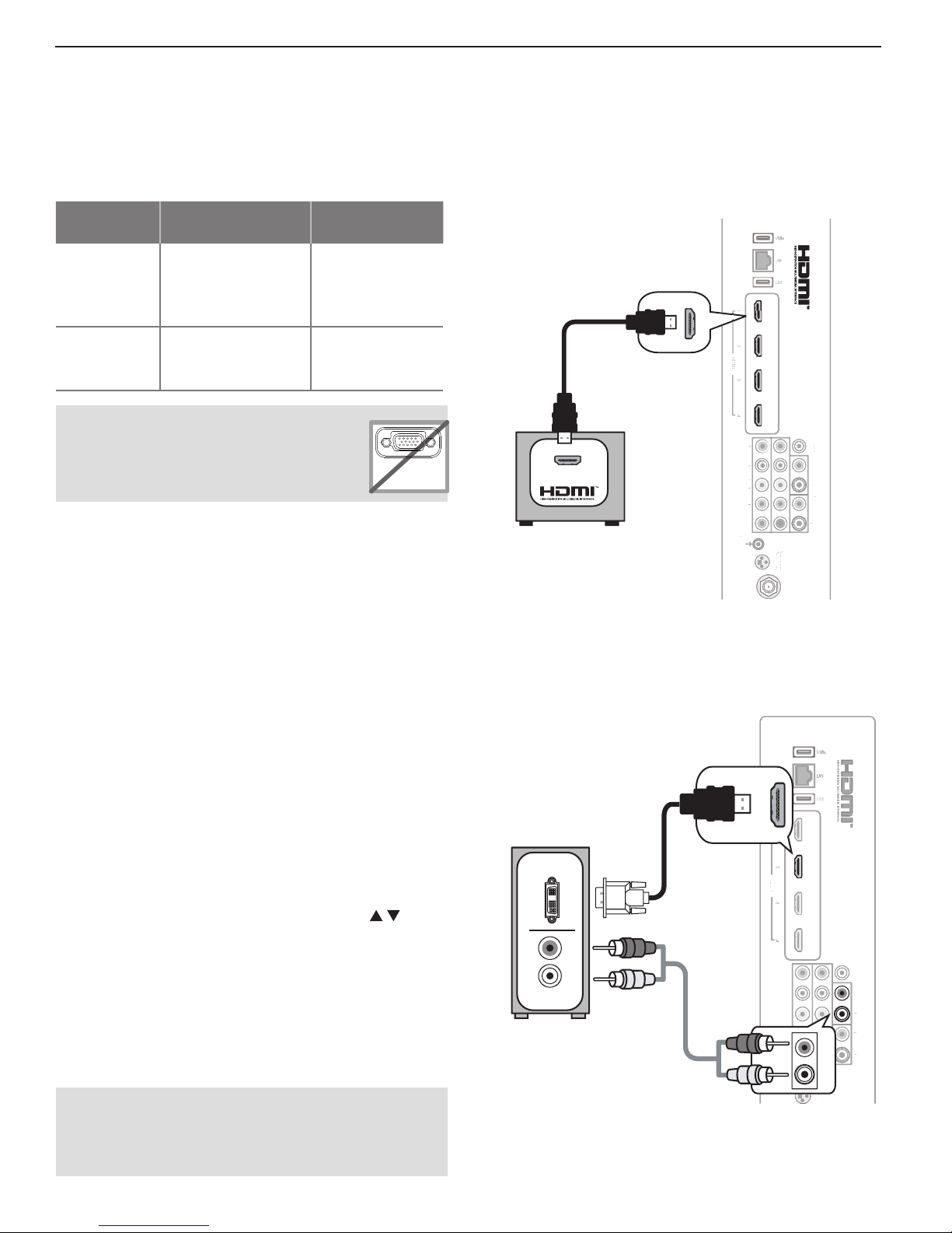
Using the TV with a Pe rsonal Computer
Connecting a Computer to the TV
Use one of the connection methods listed below based
on your computer’s video output.
Computer Video
Output
Video Connection
Digital DVI DVI-to-HDMI cable
or an HDMI cable
with a DVI-to-HDMI
adapter
Audio
Connection
Stereo audio
cables
H
DMI Connection
Mitsubishi recommends using high-speed HDMI cables
to connect newer devices incorporating HDMI technology.
HDMI cable
HDMI HDMI-to-HDMI
cable
No additional
audio connection
is required.
IMPORTANT
This TV accepts digital computer video
signals only. This TV is not compatible
with VGA (analog) computer video.
1.
Connect the computer’s digital video output to
PC MONITOR OUT
one of the TV’s HDMI jacks. See the connection
diagrams on this page for the method suited to your
equipment.
2.
Connect the computer’s audio output using one of
these options:
• For digital DVI video signals, connect the
analog audio output to the TV’s
DVI/PC INPUT
jack.
• For HDMI signals, no additional audio connection is required.
Note: If you are unable to hear audio from the
computer, there may be an incompatibility in
the computer’s hardware, software, or internal
settings. Consult a trained computer technician
for advice.
3.
Power on the TV and computer. The TV will detect
the connection and display the New Device Found
screen.
4.
In the New Device Found screen, press to
highlight PC in the list of device types. It is important to use the name PC so that the TV processes
the PC signal correctly.
5.
Highlight EXIT and press
ENTER
to close the New
Device Found screen.
Note: If your computer provides digital audio out-
put (coaxial or optical), you can connect it
directly to a digital A/V receiver and bypass
the TV.
VGA
TV
panel
OUTPUT
DIGITAL
DI
AUDIO
TP
DI
ITA
DVI/PC
DVI
R
P
INPUT
INPUT 2
EMITTER
MITTE
GLASSES
LA
3D
E
ANT
AN
R
INP
L
AVR AUDIO OUTPUT
VR A
DI
TP
L
Computer with
HDMI output
IR-External
Controller Input
IR-Ext
ontroller Inpu
rn
Y/ VIDEO
VID
Pb Pr
INPUT 1
An HDMI-to-HDMI connection carries all video and
audio on a single cable.
DVI Video Connection
TV
DVI OUT
R
L
AUDIO
Computer with
DVI and analog
stereo outputs
A DVI connection from a personal computer requires a
separate audio connection.
HDMI
DM
IR-External
Controller Input
ontroller Inpu
-
xt
rn
LR
Y/ VIDEO
Y
VID
Pb Pr
P
INPUT 1
INPUT
INPUT 2
INPUT
R
L
GLASSE
EMITTE
LA
MITTE
E
DVI/PC
INPUT
3D
D
OUTPUT
DIGITAL
DI
AUDIO
TP
DI
ITA
DVI/PC
DVI
DVI/PC
R
R
P
INPUT
INP
INPUT
L
L
AVR AUDIO OUTPUT
AVR A
R
DI
TP
L
For assistance call 1(877) 675-2224
Page 11
1. Additional TV Features 11
Using the TV with a Personal Computer, continued
Co mputer Video Adjustments
1.
Power on the computer.
2.
Select PC from the Input Selection menu. To do
this, press
move the highlight to the PC icon, and press
3.
Working from the computer, change the resolution
of the computer image. View the computer image
on the TV and maximize the computer
resolution while maintaining a suitable
aspect ratio for the image.
4.
Perform TV video adjustments. Press
VIDEO
adjustment options.
5.
Press
picture shape best suited to the
image. See the chart on this page
showing how different computer resolutions can be displayed on the TV.
INPUT
to open the Input Selection menu,
repeatedly to access video-
FORMAT
repeatedly to find the
Tip
Set the computer’s screen saver to display a pattern
after several minutes of inactivity. This acts as a
reminder that the TV is powered on.
ENTER.
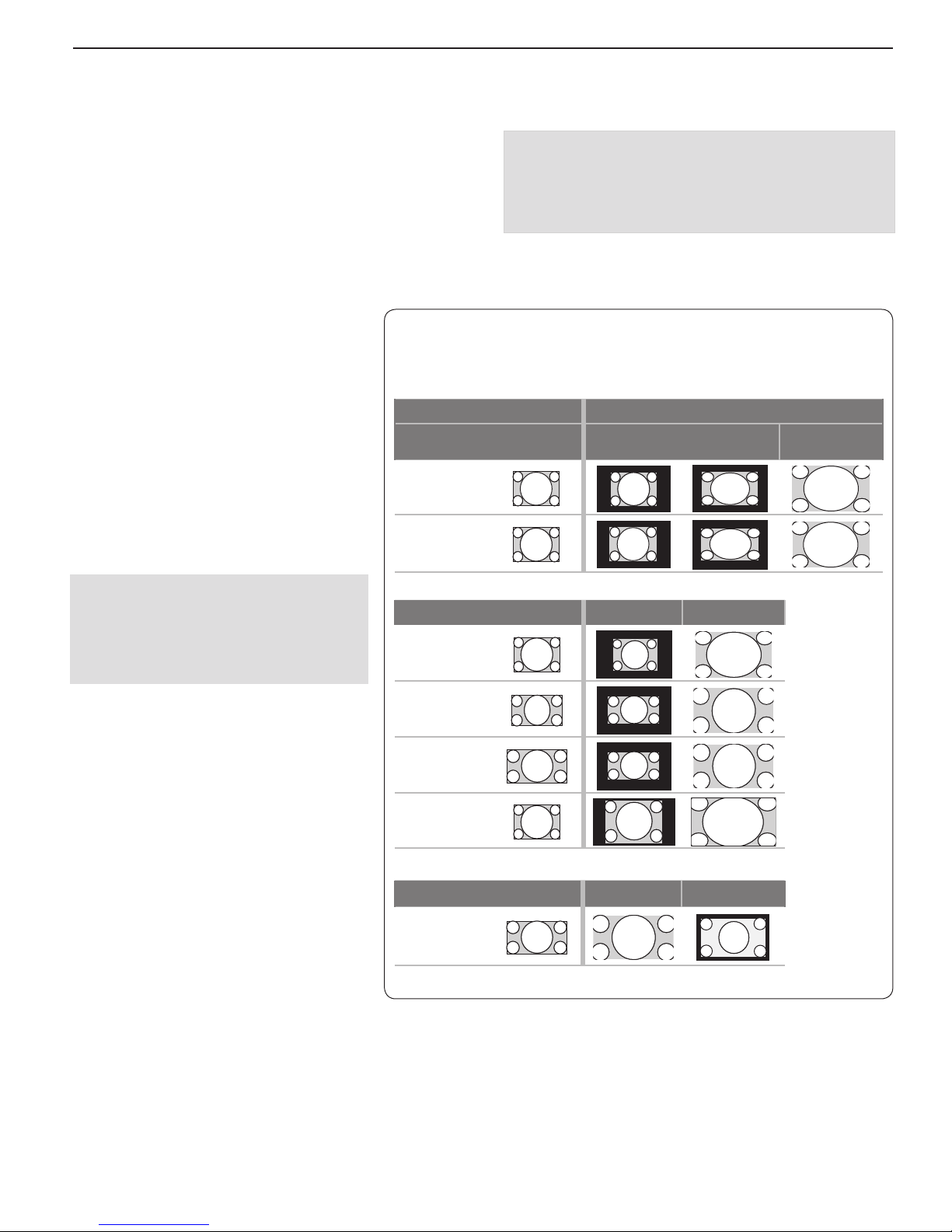
C omputer Display Formats
Press
FORMAT
your computer’s video signal.
Computer Signal
Original Format
VGA
640 X 480
SVGA
800 X 600
repeatedly to cycle through the TV displays available for
4 X 3
Standard
As Displayed on TV Screen
16 X 9
Standard
Zoom
Distortion in Computer Images
Computer images may show distortion
when viewed on the TV, e.g., lines that
should be straight may appear slightly
curved.
Image Resolution
Your Mitsubishi TV can display the resolutions shown in the chart from standard
VGA (640 x 480) through 1920 x 1080
signals at a refresh rate of 60 Hz.
In most cases, the computer will select the
best resolution match to display on the TV.
You can override this setting if you wish.
Refer to your computer operating system’s
instructions for information on changing
the screen resolution.
You may need to restart the computer for
changes to take effect.
Original Format Standard Zoom
XGA
1024 X 768
PC 720p
1280 X 720
WXGA
1360 X 768
SXGA
1280 X 1024
Original Format Standard Reduce
PC 1080p
1920 X 1080
For assistance call 1(877) 675-2224
Page 12
12 1. Additional TV Features
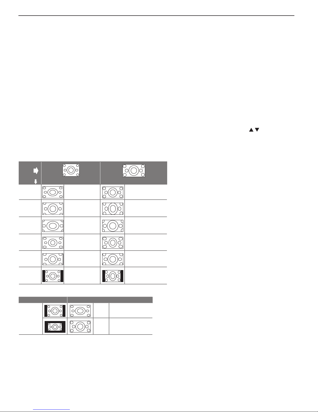
Picture Shape and Display Formats
Fo rmat Definitions
Use the
Standard: The full-screen format used by HDTV
signals. Use this format to display anamorphic DVDs
with a 1.78:1 or 1.85:1 aspect ratio. Anamorphic DVDs
with a 2.35:1 aspect ratio are displayed correctly but
with top and bottom black bars. Squarish (4:3) images
are stretched evenly from side to side. Available for all
signals.
Expand: Enlarges the picture to fill the screen by
cropping the top and bottom; useful for reducing the
letter box top and bottom bars of non-anamorphic DVD
images.
FORMAT
key to apply the formats described here.
Effect of Mitsubishi Formats on Picture Types
Original
Signal
TV Display
Format
Standard
Expand
Zoom
Stretch
Stretch
Plus
Narrow
Note 1: Available for 480i, 480p, and digital SD 4:3 signals only.
Original Signal Display Formats
SD 16:9 or
HD Digital
720p, 1080i,
1080p Signal
Non-anamorphic or SD 4:3 Anamorphic DVD
Distorted; Not
recommended.
Recommended
for letterbox. See
Note 1.
Distorted; Not
recommended.
See Note 1.
Recommended for
standard broadcasts. See Note 1.
Recommended for
standard broadcasts. See Note 1.
See Note 1
Recommended to
Wide
Expand
Zoom
remove side bars.
Recommended to remove bars from the top,
bottom, and sides.
Recommended
Distorted; not
recommended. See
Note 1.
Recommended for
anamorphic 2.35:1
images. See Note 1.
Distorted; not
recommended. See
Note 1.
Distorted; not
recommended. See
Note 1.
Distorted; not
recommended. See
Note 1.
Zoom: Enlarges the picture to fill the screen by cropping the sides, top, and bottom to eliminate black bars.
• 480i/480p and SD 4:3 signals: Eliminates top and
bottom bars on anamorphic DVDs with a 2.35:1
aspect ratio.
• 720p, 1080i, SD 16:9, and HD signals: Eliminates
bars added to squarish 4:3 images.
Stretch: Stretches a squarish 4:3 image across the
screen to display the entire image with less distortion
than the Standard format.
Stretch Plus: Similar to Stretch, but minimizes distortion on the sides by expanding the picture to crop off
portions of the top and bottom. Use to adjust the
vertical position of the picture.
Narrow: Displays narrow 4:3 images in their original shape. Adds black side bars to fill the screen.
Wide Expand: Enlarges the picture, cropping the
image on both sides. Removes or reduces black
side bars added to narrow images converted to
16:9 signals for digital broadcast.
Note: All high-definition channels send widescreen (16:9) signals, but not all programming was
created for the widescreen format. The broadcaster may stretch the image or add side bars to
fill the widescreen area.
DVD Image Definitions
Image information may be stated on the DVD
case. Some DVDs support both formats
described below.
Anamorphic (or Enhanced for WideScreen TV)
Indicates DVDs recorded to show widescreen
images properly on 16:9 TV sets using the TV’s
Standard format mode (recommended).
Non-Anamorphic (or 4:3, 1.33:1, Letter Box, or
Full Screen)
Indicates DVDs recorded for viewing on squarish TV screens. They may be full screen (4:3 or
1.33:1) which crops movies to fit the narrow TV, or
letter box, which adds black top and bottom bars.
TV Display Formats. Press the
FORMAT
different displays for the current program. Press the
see the name of the format in use.
For assistance call 1(877) 675-2224
key repeatedly to see
INFO
key to
Page 13
1. Additional TV Features 13
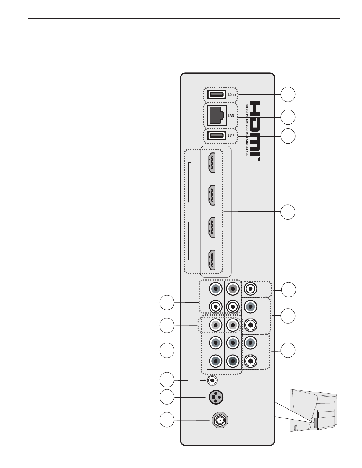
Inputs and Outputs
The Basic Owner’s Guide supplied with your TV contains connection diagrams showing how to use most of
these jacks.
1. USB (Power Only)
Standard USB 5-volt, 500-milliamp power output you
can use to supply power to an accessory device.
USBa
1
(power
only)
2. LAN
Use the
to the TV.
LAN
Ethernet jack for streaming internet video
3. USB
• The TV can read JPEG photo files and mp3 music
files from a USB storage device connected to this
input.
• This USB port can be used to power accessory
devices.
4. HDMI® Inputs
(High-Definition
Multimedia Interface)
The HDMI inputs support uncompressed standard and
high-definition digital video formats, bitstream Dolby
Digital 5.1, and PCM digital stereo audio. These inputs
are HDCP (High-Bandwidth Digital Copy Protection)
compliant.
Mitsubishi recommends you use high-speed HDMI
cables to connect newer source devices incorporating
HDMI technology. High-speed cables bring you the full
benefits of Deep Color and x.v.Color.
These HDMI inputs can also accept
digital DVI video signals.
To connect a device’s DVI
output to the TV’s HDMI
(analog audio inputs)
input, use an HDMI-to-DVI
adapter or cable plus an
analog audio. Connect the
audio cable to the
INPUT
jack on the TV to
DVI/PC
receive audio from your DVI
device.
Use the HDMI inputs to connect
to CEA-861 HDMI compliant
devices such as a high-definition
receiver or DVD player.
These inputs support
3D GLASSES EMITTER
480i, 480p, 720p, 1080i,
and 1080p video formats.
The TV’s HDMI inputs are
compatible with many DVI-D
and HDMI computer video
signals.
(composite video)
(component video)
IR-External
Controller Input
(antenna input)
R/L
Y/VID EO
Y Pb Pr
ANT
8
9
10
11
12
13
123 4
HDMI
LR
Y/ VIDEO
Pb Pr
IR-External
Controller Input
INPUT 1
INPUT 2
GLASSES
EMITTER
3D
ANT
OUTPUT
DIGITAL
AUDIO
DVI/PC
R
INPUT
L
AVR AUDIO OUTPUT
R
L
LAN
2
3
USB
4
HDMI
DIGITAL AUDIO
5
OUTPUT
DVI/PC INPUT
6
(audio input)
AVR AUDIO
7
OUTPUT
( page 6 )
For assistance call 1(877) 675-2224
Page 14

14 1. Additional TV Features
Inputs and Outputs, continued
H DMI Cable Categories
HDMI cables are available as Standard and High-Speed
types.
• High-Speed HDMI Cables. Blu-ray players, newer
DVD players, video games, 3D content, and set-top
boxes require High-Speed HDMI cables, suitable
for clock frequencies up to 340 MHz or data rates
of up to 10.2 gigabits per second. Use high-speed
cables for 1080p HD signals carrying extended color
encodings (i.e., 30 or more bits, also called Deep
Color). High-Speed HDMI cables are also suitable for
standard HDTV signals.
• Standard HDMI Cables. Standard HDMI cables
may be unmarked. They are suitable for standard
HDTV 720p, 1080i, and 1080p signals with 8-bit color
depth. Use Standard HDMI cables for clock frequencies up to 74.25 MHz or data rates of up to 2.23
gigabits per second.
5. DIGITAL AUDIO OUTPUT
This output sends Dolby Digital or PCM digital audio
to your digital A/V surround sound receiver. Incoming
analog audio is converted by the TV to PCM digital audio.
If you have a digital A/V receiver, this is the only audio
connection needed between the TV and your A/V receiver.
8. L/R (INPUT 1 and INPUT 2 audio)
Analog stereo inputs for use in conjunction with adjacent composite or component video jacks.
9. Y/
VIDEO
Analog standard-definition video inputs. Use the adjacent R and L inputs if you wish to send audio to the TV
speakers.
(Composite Video)
10. Y/VIDEO Pb Pr (Component Video)
Analog video inputs able to accept high-definition video
from a high-definition source device. Use the adjacent R and L inputs if you wish to send audio to the TV
speakers.
11. IR-EXTERNAL CONTROLLER INPUT
Accepts control signals from an external controller
when set up by your professional installer. The controller should send electronic versions of remote control
commands.
12. 3D GL ASSES EMITTER
Use this jack for the special IR emitter supplied with
some 3D glasses. The emitter sends out an infrared
signal that synchronizes your 3D glasses with the screen
display.
6. DVI/PC INPUT
Connect a DVI device to one of the TV’s HDMI inputs
and use this jack to send analog audio to the TV.
7. AVR AUDIO OUTPUT
Sends analog audio of the current program to an
analog A/V surround sound receiver or stereo system.
Digital audio from digital channels and HDMI devices is
converted to analog audio by the TV for output on this
jack. This is the only audio connection needed to the
TV if using an analog A/V receiver or stereo system.
Note: If connecting headphones, set Sound > Global >
Analog Audio Out to Variable.
13. ANT ( Antenna)
Connect your main antenna or direct cable service
(without a cable box) to
receive digital and analog over-the-air channels from
a VHF/UHF antenna or non-scrambled digital/analog
cable source.
ANT
. The
ANT
input can
For assistance call 1(877) 675-2224
Page 15
TV Menus
2
Ma in Menu
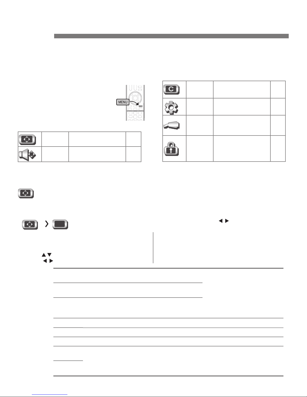
Press
MENU
on the remote control to
open the main menu.
Captions
Closed captions on/and
off; caption displays
15
20
Picture
Sound
Pi cture
Picture settings 15
Sound settings 19
Assign a name to the TV input before making video adjustments (use the New Device Found
or Inputs > Name menu). Adjustments will be reset to the defaults if you rename the input after
making adjustments.
Picture Vide o
Settings in this menu are saved for the current input only. Press to make changes and
then press
To make Video adjustments while watching TV and without
using the menu:
1. Press the
2. Press
3. Press to change the setting.
VIDEO
key.
to select a video option.
MENU
to return to the menu screen.
Setup
Inputs
Lock
Note: If the picture is too dim for your viewing environ-
ment, even after changing the Picture Mode or
brightness, go to the Setup > Energy menu and
set Ambient Light Sensor Sensitivity to Off.
Basic TV setup 21
Name assignments
for TV inputs, HDMI
Control setup
Setting a pass code
and restrictions on
TV use. Disabling the
control-panel buttons.
24
26
P icture
Mode
Super
Brilliant
Brilliant
Game
Bright For most daytime viewing and x.v.Color sources
Natural For most nighttime viewing and x.v.Color sources
Cinema
ADV1,
ADV2
ISF Day/3D,
ISF Night/2D
For use under retail lighting; not recommended for
home use.
For use under bright light; unavailable when the
current input is named
Optimizes picture and video processing for
gaming consoles. Available only when the name
of the input is
For viewing movies made for theatrical release; offers an extended color gamut.
Advanced Picture Modes. Contact your professional installer for setup. See page 17
for an overview.
Game
Game or PC.
or PC.
Set the Picture Mode first before
changing other video settings,
as some settings are stored
independently for each Picture
Mode. Use Picture Modes to get
the best image under different
viewing conditions.
For assistance call 1(877) 675-2224
Page 16
16 2. TV Menus
Picture, continued
Contrast • Low contrast shows a variety of shades in darker
images.
• In most home lighting situations, medium contrast looks
best.
• High contrast shows darker images more uniformly
black and makes colors appear more vibrant. High contrast is good for brightly lit environments.
Brightness Adjusts overall picture brightness. Settings are stored independently for each Picture Mode.
Color Adjusts overall color intensity from monochromatic to fully saturated.
Tint Adjusts the red-to-green ratio.
Sharpness Adjusts picture detail and clarity.
Color
Temp eratu re
Video
Noise
High
Low Gives white images a warm cast. Natural/
High,
Medium,
Low, Off
Gives white images a cool cast. May provide the
most realistic picture under bright lighting.
Color Temp at the low setting displays video at
approximately the 6500K industry standard for
NTSC pictures.
• High. For poor-quality signals.
• Medium.
• Low. For good-quality signals.
• Off. Leaves the picture unaltered.
For moderate noise reduction.
Adjusts the white-to-black level
Settings are stored independently
for each Picture Mode.
Adjusts the white balance. Settings are stored independently
for each Picture Mode.
Reduces minor noise (graininess)
in the picture.
EdgeEnhance
DeepField
Imager
On, Off
On, Off DeepField™ Imager dynamically enhances black levels in portions of the screen to
Demo For comparison, displays a split picture to show On (right side) and Off (left side).
EdgeEnhance™ adds special edge enhancements to make the image appear sharper.
provide strong contrast with detail over mixed screen content.
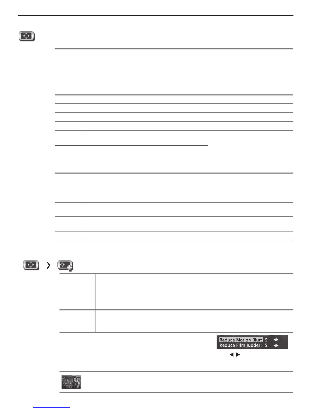
Picture Pi cture+ (Picture Plus)
Screensaver
Film Mode Auto, Off 480i and 1080i signals only.
Smooth 120
Film Motion
Test Pict u re
On, Off Select On to display a screensaver pattern while playing an audio-only input. To
use this feature, the input must either
• Be named as an audio source (e.g., CD, MP3 Player)
or
• Be the antenna input tuned to an audio-only signal.
film-decoding correction to movies filmed at 24 frames per second. Try the
setting if images show many jagged edges. Setting saved by input.
Highlight the icon and press
active, reduces motion blur in action scenes but may show
pixel structure during slower motion or in still images. Works in
conjunction with Film Mode. The adjustment side of the screen
only shows changes if the content was a film source shot at 24
frames per second.
Press
ENTER
to make changes. When
ENTER
to display a test picture.
In
Auto
, the TV automatically detects and applies
Press
to make adjustments.
Off
For assistance call 1(877) 675-2224
Page 17

2. TV Menus 17
Picture, continued
Picture Reset
• Resets sound and picture adjustments for the current input. Highlight the Reset icon and
press
ENTER
twice to perform reset
• Reset has no effect on universal settings (Balance, Listen To, Language) or on
Advanced Picture Mode settings.
.
Picture Pe rfect
PerfectColor Sliders Adjusts the saturation (intensity) of six colors for the current image source.
PerfecTint Sliders
Using PerfectColor:
Highlight the Perfect icon and press
for each TV input.
Using PerfecTint:
o switch between PerfectColor™ and PerfecTint™ adjustments, highligh
• T
• Press to move from one color bar to the next.
• Press to change settings.
• Press
• Press
CANCEL
MENU
to restore default settings.
to return to the main menu.
Adjusts six hues for the current image source.
ENTER
to display the PerfectColor menu. Settings are retained independently
t PerfectColor/PerfecTint
and press
.
Picture Adv anced
Picture > Advanced allows you to save highly customized picture adjustments for each input. Mitsubishi recommends these adjustments be
made only by a trained professional installer.
1. Press
2. With Picture Mode (the first option) highlighted,
3. Use
4. Press
5. Use
6. Press
Saving Custom 3D Settings
This menu can be used to create a custom Picture
Mode for viewing 3D content. Mitsubishi recommends
saving 3D settings under the name ADV1 and 2D set-
tings under the name ADV2.
To create a custom 3D picture mode:
• The TV must be receiving a 3D signal
• One of the TV’s 3D Source Formats must be
• You must be wearing 3D glasses matched to the
MENU
. Under Picture, highlight the
Advanced icon and press
press
ENTER
to change
ADV1
(daytime settings) or
to
highlight an option you wish to change and
press ENTER
to change settings
menu and save the adjustments for the current
input. Press
selected
emitter in use.
to see the adjustment display.
to change settings.
to
navigate to additional options and press
MENU
to return to the Picture > Advanced
EXIT
to close the menu
ENTER
from blank (undefined)
ADV2 (nighttime settings).
.
Locking Custom Picture Mode Settings
.
to
.
Once set up, you can protect custom Picture Mode settings with a pass code. With the Picture > Advanced
menu displayed, highlight the Picture Mode name and
press keys
7
4 1 5 3 6 9
Once locked, the name of each Picture Mode changes:
ADV1
is locked as
ADV2 is locked as ISF Night/2D
Use the same key sequence to unlock the settings and
make changes.
To Use a Custom Picture Mode at a Later Time
• Press
• Press
To Return to the Default Values for Advanced
Display the Picture > Advanced menu and:
1. Highlight the name of the Advanced mode to change.
2. Highlight RESET Pic Mode and press
VIDEO
option. Press to select the desired mode.
MENU
Mode and select the desired mode.
must perform the reset separately for both ADV1
and ADV2.
ISF Day/3D
and use to find the Picture Mode
and go to Picture > Video > Picture
ENTER
ENTER
.
. You
For assistance call 1(877) 675-2224
Page 18

18 2. TV Menus
Picture, continued
Picture 3 D Mode
Source
Format
Automatic • When the TV receives a 3D signal from an HDMI 1.4a-compliant device, forces
Side-by-Side
Top/ bottom
Checkerboard
2D+ Depth When active, generates a simulated 3D image from an ordinary 2D image.
Glasses
Emitter
Internal
Glasses
Emitter
External
Depth • Available only when Source Format is set to Automatic, Side by Side, Top /
DLP Link
Standard,
Reverse, Off
Standard,
Reverse
Standard,
Reverse, Off
Off Turns off 3D mode for the current input. Restores normal TV operation for an ordi-
nary 2D signal.
the TV automatically into 3D mode and selects the correct 3D format.
• When the TV receives a normal 2D signal, makes the TV automatically exit 3D
mode.
3D formats supported by the TV
• For use with the TV’s internal emitters
• Select the Off setting when using an external IR
emitter to prevent IR interference.
For use with an external emitter connected to the
TV’s
3D GLASSES EMITTER
Bottom, or 2D+ Depth.
• Highlight the icon and press
• Allows adjustment of the 3D effect from a flatter image to one with more depth.
• For use with DLP Link.
• Select the Off setting if you are not using DLP
Link glasses.
jack.
ENTER
to display the adjustment screen.
Use the Standard or
Reverse setting to synchronizes left/right images to
work with your 3D glasses.
Use the Standard or
Reverse setting to synchronizes left/right images to
work with your 3D glasses.
Notice Concerning Format Compatibility
The Mitsubishi TVs will support the mandatory HDMI
1.4a 3D signals intended for the United States. Specifically, the TVs will support the 3D signals known as
Frame Packing 1080p@24 Hz and 720p@60 Hz (primarily from Blu-ray players and gaming consoles), Sideby-Side(Half) 1080p@24/30/60 Hz, 1080i@60 Hz, and
720p@60 Hz, Top-and-Bottom 1080p@24/30/60 Hz
and 720p@60 Hz, and Checkerboard 1080p@60 Hz.
However, there may be some 3D sources that are not
For assistance call 1(877) 675-2224
compatible with the TVs. In all cases: (1) 3D sources
must connect to the TVs using the HDMI inputs or via
StreamTV™ Internet Media; and (2) Active Shutter 3D
glasses that match the TV’s internal synchronization
emitter, or Active Shutter 3D glasses with their own
external matching synchronization emitter connected to
the rear of the TV or DLP Link Active Shutter 3D glasses
are required in order to view 3D content.
Page 19

2. TV Menus 19
S ound
Sound Au dio
Settings in this menu are saved for the current input only with the exception of TV Speakers
and Balance, which applies to all inputs. Press to make changes and then press
return to the menu screen.
To make Audio adjustments while watching TV and without using the menu:
1. Press the
2. Press to select an audio option.
3. Press to change the setting.
TV Speakers On Turns on the internal TV speakers.
Balance Controls audio balance between the right and left TV speakers.
Sou nd Mode Stereo No special audio effects from the TV speakers.
Level Sound On, Off Reduces differences in sound volume between programming segments, such as the
Li sten To
(applies only
to analog
channels from
ANT
the
AUDIO
key.
Off
Turns off the internal TV speakers so you hear sound only from a connected A/V receiver.
Note: When you disconnect an A/V receiver, be sure to change the Sound setting
to TV to hear sound from the TV speakers.
Bass Controls volume of low-pitched sound from the TV speakers.
Treb le Controls volume of high-pitched sound from the TV speakers.
Surround Modifies audio from the TV speakers.
• For monaural (non-stereo) programs, creates a simulated stereo effect.
• For stereo programs, creates a simulated surround sound effect.
difference between regular broadcast programs and commercial segments.
Mono Reduces background noise. Use when receiving a weak stereo audio signal. All
audio is played as mono.
Stereo The TV plays stereo broadcasts in stereo and mono broadcasts in mono. The word
input)
(Second Audio
Program)
Stereo is displayed when you tune to a channel broadcasting in stereo.
SAP
Selects an additional monaural sound track not audible during normal TV viewing.
The SAP signal might be related to the program (such as a sound track in a foreign
language), or it might be unrelated (such as a weather report). If an SAP signal is
broadcast, the letters SAP are displayed when you tune to the channel.
MENU
to
Sound Glo bal
Settings in this menu apply to all inputs.
jack.
Analog Audio
Out
Fixed Use with an analog A/V receiver. Control volume from the A/V receiver. The
volume of the audio output signal is fixed and is unaffected by the TV’s volume
control.
Variable Use with headphones. Adjust headphone volume using the TV’s volume controls.
When set to Variable, the audio output signal is adjustable from the TV’s volume
controls.
These settings affect audio from the AVR AUDIO OUTPUT
For assistance call 1(877) 675-2224
Page 20

20 2. TV Menus
C aptions
Captions on Digital Channels
The TV can decode captions from the ANT input only.
Broadcasters can send up to six different captioning
selections or can send analog captions for a program
that originated in analog format. A TV station may broad-
cast only one or two types of captions or none at all
Captions on Analog Channels
The TV can decode captions from the
the composite
either standard closed captions or text service. Standard
closed captions follow the dialogue of the program and
display in a small section of the screen. Text-service closed
captions often conta
news and cover a large portion of the screen.
VIDEO
jacks. Broadcast
in information such as weather or
ANT
input and
ers can send
.
IMPORTANT
• Analog text-service options display a large
black or gray box on the screen when no
caption signal is being broadcast.
• The content of captions is determined by the
broadcaster. If captions show strange characters, misspellings, or odd grammar, it is not
a malfunction of the TV.
•
Closed-caption signals are not available through
HDMI or component jacks. See the menus for
devices connected to these inputs for closedcaption decoding.
Captions Services
Service On if Mute, On, Off On if Mute: Displays digital closed-caption signal Caption 1 (digital) or CC1
(analog) when audio from the TV speakers is muted. While watching TV,
press
MUTE
to turn closed captions on/off.
Digital Caption 1–Caption 6 Caption signals sent by the broadcaster.
Analog
CC 1–CC 4
Tex t 1–Text 4
• CC 1–CC 4. Standard closed-caption signals
• Tex t 1–Text 4 . Tex t-se r v i ce sig nals
Captions Font
These choices apply to digital captions only.
Style As Broadcast or
choice of font styles
(digital captions only)
Size
Large, Medium, Small
As Broadcast changes settings to those selected by the captions provider,
or, if none, to the TV’s own caption defaults. Use one of the font styles to
give digital captions a custom appearance.
Large is recommended.
Captions Color
Font White, Black, Magenta, etc. Recommendations for digital captions:
Opacity
Background
Color
Background
Opacity
For assistance call 1(877) 675-2224
Translucent, Opaque, Flashing, Transparent
White, Black, Magenta, etc.
Translucent, Opaque, Flashing, Transparent
• A white font on a black translucent back-
ground makes an easy-to-read combination.
• Use contrasting colors for captions and back-
ground.
Page 21

2. TV Menus 21
Setup
Setup La nguage
Menu English
Spanish
Antenna
Digital
Audio
Selects the current language for a digital program from the
up to seven language choices or no language choice.
Displays on-screen menus in either English or Spanish.
ANT
input. A digital program may include
Setup Cl ock
Set the TV clock to:
• Use the TV Timer to power on the TV automatically at a time you specify
• Lock the TV by time
Note:
• When the Daylight Saving Time change occurs, you must open this menu and set the TV’s clock ahead or back.
• You must reset the TV’s clock after an interruption of power such as unplugging the TV’s power cord.
Time
Date
Time
Zone
Highlight the Clock icon and press
• Press
• Press t
• Press
Eastern, Central, Mountain, Pacific, etc.
ENTER
to select the item to change.
o change values.
to move to another column.
ENTER
Press
or to highlight the time. To edit time and date:
ENTER
to confirm entries.
Daylight
Savings
Off, On Select the setting for your area.
Setup Timer
The Timer tells the TV to power on automatically at a time you set. Use this menu to set a day,
time, input, and channel for the Timer. If the TV is already on at the set time, the TV will automatically change to the designated channel or input.
• The TV clock must be set before you can use the Timer feature.
• As a reminder that the TV Timer is set, the TV
•
When the Timer turns on the TV, press any key on the remote control to keep it from turning off after five minutes.
Ti mer On, Off Select On to enable the Timer.
Day Daily, Mon-Fri, (every) Sunday, (every) Monday,
(every) Tu esday, etc.
Time To set the time for the TV to come on:
1. Highlighted the time and press
2. Press t
Input Ant, DVD, VCR, etc.
Select the input you want displayed when the TV comes on. Choose from the defined and enabled
inputs that appear in the Input Selection menu.
Channel
If the source is the
o change values.
ANT
input, press to select a channel number or press and hold to scroll quickly.
POWER
ENTER
Press
indicator flashes slowly while the TV is powered off.
Select the day or days of the week for the Timer to
turn on the TV.
.
ENTER
to confirm entries.
For assistance call 1(877) 675-2224
Page 22

22 2. TV Menus
Setup, continued
Setup Cha nnel
Ant Air,
Ant Cable
All Channels,
Add only new
channels
Scan
E dit After channel scan, Edit lets you add and delete memorized channels. Memorized channels are
Adding/Deleting Channels Using the Channel Edit Menu
• Channels marked with a check are in memory.
• To add or delete a channel from memory, highlight
the channel number and press
• To add a single digital channel not in the list, see the
notes under Scan on this page .
• Digital channels are listed by virtual channel number
with the physical channel number shown in small
gray text.
You must perform a channel scan to receive digital channels. The scan searches for broadcast channels and adds them to TV memory. To start channel scan:
1. Highlight one of the input selections based on your connection to the ANT input
• Air when connected to an indoor or outdoor antenna.
• Cable when connected to direct cable (no cable box).
2. Select the scan type.
• Select All Channels for an initial scan or after moving the TV to an new area with a differ-
ent channel line-up.
• Select Add only new channels to search for channels newly broadcasting since the
previous scan.
3. Press to highlight SCAN.
4. Press
See below for additional notes on Scan.
those you can tune using the CH key. Edit the channel list to limit tuning to channels you watch.
• Press
• Press to move through all channel numbers, one at a time.
ENTER
to start channel memorization.
CH/PAGE
to jump to the next or previous page of channel numbers.
ENTER
.
:
- Virtual Channel Number (digital channels only).
A channel number sent by a local broadcaster.
- Physical Digital Channel Number. The
channel number officially assigned to the actual
broadcast frequency; shown on screen in gray
text.
Notes on Sca n and Channel Memorization
• Channel memorization may take up to 15 minutes to
complete.
•
To stop channel memorization before completion, press
CANCEL. Channels already added are retained
• When watching TV, press CH to move through
memorized channels. Press and hold CH to speed
through channels.
•
To add a digital channel that does not appear in the
Edit menu without performing channel memorization:
1. Look up the physical channel number for
the new digital channel. See the website
www.antennaweb.org for help.
2. Press
For assistance call 1(877) 675-2224
INPUT
and select the
ANT
input.
3. Use the number and
physical channel number followed by “-1” and
ENTER
. For example, for physical channel 36,
3 6
.
The TV will search for a digital channel on the
channel 36 frequency. When it finds the channel, it
will:
a. Add the channel to memory.
b. Change the channel number to the virtual
channel number sent by the broadcaster.
c. Add to memory any associated sub-chan-
nels.
• Rememorize channels if you move the TV to a different geographic area with a different channel line-up.
1
CANCEL
keys to enter the
ENTER
.
Page 23

2. TV Menus 23
Setup, continued
Setup Energy
Ambient Light Sensor When on, automatically adjusts picture brightness based on room lighting.
Blue Glow Select On to see blue accent lighting when the TV is powered on.
Setup Network
Ethernet Connection DHCP (automatic), Manual
[Connection Data]
Wireless Connection [Network ID]
[Connection Data]
Off. Turns off the TV’s wireless system radio receiver. Use this option if there is RF inter-
ference with other devices.
For assistance call 1(877) 675-2224
Page 24

24 2. TV Menus
Input s
Inputs N ame
INPUT and HDMI jacks:
Cable box, Cam(corder), CD,
DVD (DVD, DVD2, Blu-ray), DVR,
Game (Game, PS, Xbox, Wii),
Media Box, PC, Satellite, AVR,
On/Off (ANT only)
INPUT
jacks
only:
CD/Audio, MP3 Player, VCR
HDMI
jacks
only:
PC, AVR, Delete
General Notes for the Inputs > Name Menu
When you change an input name and then exit the
Name menu:
• The name is changed
• The icon in the Input Selection menu is changed
• Audio and video settings are changed to the
defaults for the new device type.
Notes for HDMI devices
• Disconnecting an HDMI device: When you disconnect an HDMI device, the icon remains in the
Input Selection menu until you remove it. Select
Delete in the Inputs > Name menu to remove an
unwanted icon for an HDMI input.
• HDMI Control and CEC-Enabled Devices: See
“HDMI Control of CEC Devices” on page 30 .
• Lets you assign or change the names of inputs appearing in the Input
Selection menu. Highlight an input and press
through the name choices.
• Lets you turn the Ant input On/Off to display or hide them in the Input
Selection menu; highlight the input and press
and Off.
• Lets you delete unused HDMI inputs from the Input Selection menu.
• A CEC-enabled tuner can be named either Cable Box or Satellite.
• A CEC-enabled DVD player can be named DVD, DVD2, or Blu-ray.
ENTER
multiple times to cycle
ENTER
to switch between On
• In case of CEC conflicts: Turn off CEC signals in
one of these ways:
- Turn off the TV’s HDMI Control signals to the
device (Inputs > HDMI Control menu).
- Turn off each device’s internal CEC capability.
See “HDMI Control of CEC Devices” on page 30 for
the TV’s HDMI Control or, to turn on/off a specific
device’s response to CEC signals, see the device
owner’s manual.
• If the New Device Found screen does not display
as expected when you connect an HDMI device:
a. Power off the device.
b. Disconnect the HDMI cable.
c. Press
d. Go to Inputs > Name.
e. Highlight the HDMI input name and press
f. Press
g. Connect the new device and the New Device
MENU
on the TV remote control to enter
the TV main menu.
to select Delete.
EXIT
to clear the menus.
Found screen will display.
ENTER
For assistance call 1(877) 675-2224
Page 25

2. TV Menus 25
Inputs, continued
HDMI
Inputs
Inputs O rder
1. Press to highlight an input icon.
2. Press
3. Press to drag the icon to the desired position.
4. Press
Control
On, Off
Lets you rearrange icons in the Input Selection menu.
ENTER
to confirm the selection.
ENTER
to confirm the new position.
Select On or Off to enable or disable the TV’s control of a CEC-enabled device.
See “Enabling HDMI Control of CEC Devices” on page 30 for use of this
feature.
Inputs
StreamTV
Inputs Demo
Inputs Update
Internet Services
Deactivation
See demonstrations showcasing selected TV features.
Provides instructions for updating TV software.
Highlight the service name and press
information stored in the TV.
ENTER
to purge your account
For assistance call 1(877) 675-2224
Page 26

26 2. TV Menus
L ock
TV Locks
Parental
Time
Channel
Panel
Other
Lock by Program Ratings
Restricts access using U.S.-based ratings
sent by broadcasters.
Lock by Time
Restricts TV use by time of day.
Lock by Channel
Blocks access to the channels you specify.
Lock Control Panel
Disables the buttons on the TV’s control
panel. Use this feature if small children
in the home try to press buttons on the
control panel.
Lock by Other Program Ratings
Restricts access using non-U.S.-based
ratings sent by broadcasters.
Pa ss Code
Setting a Pass Code
You are prompted to enter a pass code whenever you
select Lock on the main menu. To set a pass code for
the first time:
1. Press
2. Input a four-digit pass code using the number keys
3. Enter the code a second time to confirm.
MENU
and highlight Lock. A screen prompt-
ing you for a pass code will display.
on the remote control.
• Press
• Press
CANCEL
back one space.
MENU
setting a pass code.
to delete a number and move
or
EXIT
to close the menu without
Other Menu (Alternate Rating System)
This TV can recognize new rating systems that may
come into effect in the future. The Other menu allows
you to block digital programming when such systems
come into effect. The Start Time and Stop Time
options in the Parental menu apply to U.S.-based
ratings only and do not affect alternate rating systems.
The first time you tune to a channel broadcasting an
alternate rating system, the TV defaults to the most
restrictive setting if the Lock menu > Other Lock
option is set to On. Use this menu to change the
allowed rating if you are unable to watch a program
rated with an alternate system.
Important Notes on Rating Locks
•
Parental menu rating locks apply only to channels and signals received on the ANT
posite
• Other
nels received on ANT
• When viewing a cable box, satellite receiver,
or other device connected to the component
Y Pb Pr
owner’s guide for parental locks.
VIDEO
jacks.
menu rating locks apply only to digital chan-
.
or
HDMI
inputs, check the device’s
and com-
Resetting a Pass Code
See the procedure in “Bypassing TV Locks” on page 27 .
P arental Menu
The TV comes from the factory with the rating locks
turned off and with pre-set U.S. ratings TV-PG and
movie rating PG. You must turn on blocking for U.S.
ratings to activate these rating restrictions. Use the
Lock > Parental menu to change the level of blocking
with U.S. ratings.
Any time you change the channel or device, it may take
up to five seconds for the rating restrictions to take effect.
For assistance call 1(877) 675-2224
Page 27

2. TV Menus 27
Lock, continued
Using TV Locks
After you set the lock, you must use your pass code to:
• View a locked program
• View a locked channel
• View the locked TV
• Cancel the lock
• Open the Lock menus
Tips for Using the Lock Menu
When entering the Lock menu, you will be prompted to
enter a pass code.
• To change the pass code, press 9 and
same time. Either enter a new pass code to open
the Lock menu and make changes or press
close the menu.
• If any of the locks are turned on and you exit the
menus when prompted for a new code, the old code
and all lock settings will be retained.
LAST
at the
EXIT
to
• If all locks are turned off and you exit the menus
when prompted for a new code, then the previous
code will be erased.
Bypassin g TV Locks
• If you try to watch a blocked program or channel
or the TV is locked by time, a notice will appear
prompting you for a pass code. To use the TV, input
ENTER
your four-digit pass code and press
• To reactivate the locks after using a pass code,
power the TV off and then on.
• If a program is blocked, you can still use the TV
without entering a pass code. Change to a channel
airing an allowed program or change to another
device.
• If you forget your pass code, you can view the
locked TV without entering your pass code. When
prompted for the pass code, press the number 9 and
LAST
keys on the TV remote control at the same time.
This process temporarily unlocks the TV.
.
IMPORTANT
When changing or deleting your pass code,
you must use the remote control included
with this TV. You cannot use a Mitsubishi
remote control from another component or a
“universal” remote.
For assistance call 1(877) 675-2224
Page 28

28 2. TV Menus
Lock, continued
Lock Par ental
Lock
TV Rating
Movie
Rating
Start Time/
Stop Time
Disables or enables blocking based on V-Chip signals and the U.S. rating system.
Highlight the rating level you wish to change and press
block it (
You can apply supplemental content blocking to the age-based
ratings by using the TV content categories. (FV, D, L, S, V)
Highlight the rating level you wish to change and press ENTER
Sets the time of day for enforcement of rating restrictions chosen in the Parental menu. The TV
clock must be set in the Setup > Clock menu before you can use Start Time/Stop Time. To make
rating restrictions active 24 hours a day, make Start Time and Stop Time the same.
1. Highlight the start time or stop time.
2. Press
3. Press to make changes.
4. Press
) or allow it (
ENTER
to start editing.
ENTER
to confirm changes.
).
ENTER
to block it (
to
) or allow it (
).
TV Program Ratings
TV-Y
TV-Y7
TV-G
TV-PG
TV-14
TV Age-Based Ratings
TV-MA
FV
D
TV Content Categories
Yout h . For children under 7.
Youth 7 and older.
General Audience. For the entire family.
Parental Guidance. Parental Guidance
recommended; may not be suitable for
some children.
Adolescent 14 and older. Not recommended
for children under 14.
Mature Audience. For adults only.
Fantasy Violence. Applies to TV-Y7 only.
Sexual Dialog. Applies in differing
degrees to TV-PG and TV-14.
L
Adult Language. A
degrees to TV-PG, TV-14, and TV-MA.
S
Sexual Situations. Applies in differing
degrees to TV-PG, TV-14, and TV-MA.
V
Violence (graphic or realistic). Applies in dif-
fering degrees to TV-PG, TV-14, and TV-MA.
pplies in differing
Movie Ratings
G
General Audience. Designed for the
entire family.
PG
PG-13
NC-17
Not
Rated
Parental Guidance. Parental Guidance
recommended; may not be suitable for
some children.
Parental Guidance, 13 and Older. Not
recommended for children under 13.
R
Restricted. Restricted in theaters to 17
years old and older unless accompanied
by an adult.
No Children 17 or Under. Restricted
in theaters to 18 years old and older.
X
Adult. Designed for and restricted in
theaters to adult audiences only.
No MPAA rating assigned
For assistance call 1(877) 675-2224
Page 29

2. TV Menus 29
Lock, continued
Lock Time
Lock by Time
Lock Time,
Unlock Time
Enables/disables Lock by Time.
To set the lock and unlock times:
1. Highlight the lock or unlock time.
2. Press
3. Press to make changes.
4. Press
Note: T
Lock Channel
Lock Panel
Blocks all use of the TV during the time period you specify. You must enter a pass code to use
the TV when the time lock is in effect. After releasing the lock with the pass code, the lock does
not go back into effect until the next time the TV is powered on.
ENTER
to start editing.
ENTER
to confirm changes.
o make Lock by Time active 24 hours a day, make Start Time and Stop Time the same.
The Channel Lock menu lists channels currently in memory (see page 22 ). Highlight a
channel and press
cleared the next time you perform a channel scan.
ENTER
to lock (
) or allow (
) the channel. Channels locks will be
Off, On On locks and Off unlocks the buttons on the TV’s control panel. Use this option if small children try
to press TV buttons.
• To release the Panel Lock from the TV’s control panel, press and hold the
seconds. If the TV is powered off, press
• To reactivate the lock, return to this menu and change the setting to On.
POWER
after the lock releases to make the TV power on.
INPUT
button for ten
Lock Other
Other Menu Options (alternate rating system)
This TV can recognize new rating systems that may come into effect in the future. Such alternate rating systems will apply only to digital programming received on the
Lock On, Off Enables/disables program blocking.
System
Group Rating groups available in the rating system shown on the screen. Rating groups are defined by the
Rating Rating restrictions available in the selected rating system and group. Highlight the rating and press
The rating system available for the channel
rating system in effect.
ENTER
to check (block) or uncheck (allow) rated content.
ANT
input.
For assistance call 1(877) 675-2224
Page 30

30
3
HDMI C ontrol of CEC Devices
Many newer HDMI devices have a feature called
Consumer Electronics Control (CEC) or HDMI Control.
HDMI Control allows one device, such as the TV, to
control other devices, such as an A/V receiver or disc
player. Use of CEC is optional.
Each manufacturer chooses which CEC functions to
support so it is difficult to predict which devices and
features are compatible with Mitsubishi’s HDMI Control.
You may find that CEC functions for a specific device are
limited.
To use HDMI Control, you must enable it in both
the TV and the device.
• In the TV. Enable HDMI control from the New
Device Found screen or from the Inputs > HDMI
Control menu.
• I
n the Device. Most devices with HDMI CEC com-
patibility let you turn it on or off in the device menus,
where it is typically listed as “HDMI Control.”
Enabling HD MI Control
of CEC Devices
To ensure proper detection
• Power on HDMI devices before connecting
them to the TV.
• Connect and set up HDMI devices one at a
time.
1.
Power on the device and allow it to complete the
power-on sequence (boot up). Stop any playback.
2.
Connect the device to one of the TV’s HDMI inputs.
3.
When the TV detects the connection, the New
Device Found screen will appear.
Note: See “If the New Device Found Screen Has No
HDMI Control Option” on this page if an HDMI
Control option is not offered.
New Device Found screen with HDMI Control option.
This screen displays only if the device’s HDMI Control is
enabled
For assistance call 1(877) 675-2224
.
4.
If prompted for a name, highlight a name for the device
and press
check. The device itself may
later override the name you
assign.
5.
Highlight On and press
to add a check.
6.
Highlight EXIT and press
Device Found screen.
Note: At any time after completing Auto Input Sens-
ing, you can set the TV’s HDMI control on or off
in the Inputs > HDMI Control menu.
ENTER
to add a
ENTER
ENTER
to close the New
If the New Device Found Screen
Has No HDMI Co ntrol Option
If the New Device Found screen shows no option for
HDMI Control, one of these conditions applies:
• HDMI Control is turned off in the menus of the
new device
Action:
a. Highlight EXIT and press
New Device Found screen.
b. Display the device’s setup menus and enable
the device’s CEC capabilities.
c. Wait for the TV’s New Device Found screen
to appear again.
d. If the New Device Found screen does not
appear, power off the device. Power on the
device and wait for the New Device Found
screen to display with the HDMI Control
option.
• The HDMI cable cannot support CEC
Action:
Upgrade your HDMI cable to one that supports
CEC.
• The device does not have CEC compatibility
Action:
Control the device with its own remote control or
program the TV’s remote control to operate the
device.
ENTER
to close the
Page 31

3 HDMI Control of CEC Devices 31
t
A
U
O
OU
UT
G
L
U
O
OU
UT
2
1
/
C
LRL
R
INPUT
C
t
P
b
r
L
/
E
O
HDMI Control of an HDMI A/V
Receiver and Connected Devices
1.
Enable HDMI Control for the A/V receiver as
described in “Enabling HDMI Control of CEC
Devices” on the opposite page .
2.
Power on the HDMI device you wish to connect to
the A/V receiver (such as a disc player, cable box,
or satellite receiver). Allow the device to complete
the power-on sequence (boot up). Stop playback if
the device starts playing.
3.
Select the device’s HDMI input on the A/V receiver’s front panel controls or remote control.
4.
Connect the device to the A/V receiver with an
HDMI cable.
5.
When the TV detects the connection, the New
Device Found screen will appear.
Note: If the TV is unable to detect the device, either
the device’s CEC capability is not enabled or
the device is not CEC compatible. Enable
HDMI control through the device’s menus
before continuing. You may need to temporarily connect the device directly to the TV to view
device menus.
6.
Highlight On and
press
ENTER
to
add a check.
7.
Highlight EXIT and press
Device Found screen.
8.
Optional: Connect the TV’s
OUTPUT
to an input on the A/V receiver. Use this
additional connection if:
• You want the ability to switch between the A/V
receiver speakers and the TV speakers.
• You want to use the A/V receiver to listen to
devices connected to the TV only, e.g., an
antenna input or camcorder.
ENTER
to close the New
DIGITAL AUDIO
If your A/V receiver converts
all video signals for output
on HDMI, you can use any
connection types from
external devices; content
can be HD or SD video.
DVD
player
Cable
box
VCR
A/V receiver with
HDMI output
HDMI OUT
DIGITAL
AUDIO IN
HDMI
cable
OUTPUT
OUTPUT
DIGITAL
DI
DIGITAL
A
AUDIO
AUDIO
TP
DI
ITA
DVI/PC
DVI
INPUT 2
INPUT
R
L
R
L
P
INPUT
AVR AUDIO OUTPUT
VR A
DI
TP
TV
L
Y/ VIDEO
Y
VID
Pb Pr
P
IR-E
Con
IR-E
INPUT 1
INPUT
on
OUTPUT
DIGITAL
AUDIO
Optional digital
audio connection
Connecting HDMI devices. The optional digital audio
connection allows you to hear audio through the A/V
receiver from devices connected to the TV only.
To hear audio from a device without HDMI Control, you
must manually select the correct A/V receiver input for
the device.
For assistance call 1(877) 675-2224
Page 32

32 3 HDMI Control of CEC Devices
Resolving CEC Conflicts
Because each manufacturer selects which CEC functions to support, some devices may conflict with other
devices. If control conflicts arise, you can:
• Turn off TV control of an individual CEC-enabled
device (see below).
• Turn off CEC in the device itself. Refer to the
device’s Owner’s Guide for instructions.
Turning Off the TV’s HDMI Control of a CEC
Device
1.
Press
MENU
on the TV remote control.
2.
Highlight Inputs > HDMI Control.
3.
Move to the device name and press
Off to turn off the TV’s ability to control the device.
4.
Press
EXIT
to clear the menu.
ENTER
to select
Using H DMI Control
As an example of using HDMI Control, press
the device itself to:
• Power on the TV
• Switch to the device (no need to display the
Input Selection menu)
• Begin play of the device
Direct Keys
Test your equipment with the TV’s remote control to
find additional supported commands. See the table
below for commands that may be available, depending
on the individual device.
CEC-enabled VCR, DVD, and DVR functions that
may be available:
Record/
Playback
Menu
Navigation
ENTER
CANCEL
(to cancel)
Channel
Tuning
CH GUIDE
Digits
0–9
,
CANCEL
ENTER
PLAY
on
Other
TOOLS
Check the
TOOLS menu
for supported
functions.
Inputs > HDMI Control menu
Remo ving an HDMI Device
1.
Power off the device.
2.
Disconnect the HDMI cable.
3.
Press
MENU
on the TV remote control to enter the
TV main menu.
4.
Go to Inputs > Name.
5.
Highlight the HDMI input name and press
select Delete.
6.
Press
EXIT
to clear the menus.
Inputs > Name menu with Delete selected for HDMI-3.
ENTER
to
If you have a CEC-enabled A/V receiver, CEC-enabled
devices connected to the A/V receiver with an HDMI
cable may also be controllable. They can be selected
from the TV’s Input Selection menu.
CEC-enabled A/V receiver functions that may be
available:
• Try the
• To open the A/V receiver menu, follow these steps:
1. While watching TV, press
2. Press until the TV Speakers option displays.
3. Press to select Off (to send audio to the A/V
4. Press
5. Press
6. Select Menu from the Tools menu.
VOL, MUTE
receiver).
INPUT
in the Input Selection menu.
TOOLS
, and menu-navigation keys.
AUDIO
and highlight the A/V receiver icon
.
.
For assistance call 1(877) 675-2224
Page 33

Appendices 33
Appendix A: TV Care
Cl eaning Recommendations
Normally, light dusting with a dry, non-scratching duster
will keep your TV clean. If cleaning beyond this is
needed, please use the following guidelines:
First, turn off the TV and unplug the power cord from
the power outlet.
Occasionally clean dust build-up from the air-intake
grilles on the back and sides of the TV. Clean using a
vacuum cleaner with a brush attachment.
Top and Sides of the TV
• Gently wipe down your TV with a soft, non-abrasive
cloth such as cotton flannel or microfiber, or a clean
cloth diaper, lightly moistened with water. Dry with
a second dry, soft, non-abrasive cloth.
• For oily dirt, add a few drops of mild liquid detergent, such as dishwashing detergent, to the water
used to moisten the cloth. Rinse with a second
cloth moistened only with water. Dry with a third
dry, soft, non-abrasive cloth.
Ca re of the Remote Control
Remote Control Tips
• For longer life, use alkaline batteries.
• Do not mix old and new batteries.
• Be within 20 feet of the equipment.
• Do not press two or more keys at the same time
unless instructed to do so.
• Do not allow the unit to get wet or become heated.
• Keep the unit out of direct sunlight.
• Avoid dropping on hard surfaces.
• Do not use harsh chemicals to clean. Use only a
soft, lightly moistened cloth.
Low-Battery Indicator
If you press a key and the mode indicator blinks five
times, replace the remote control’s batteries.
Screen
• Follow the instructions for the top and sides, wiping
gently in an up and down motion.
• Clean the entire screen evenly, not just sections of
the screen.
• Do not allow liquid to drip down the screen, as
some liquid may enter the TV through the gap
between the screen and screen frame.
• You may purchase Mitsubishi Screen Cleaner, part
number CLEANER-VSS, by calling (800) 553-7278.
General Cleaning Precautions
• DO NOT allow liquid to enter the TV through the
ventilation slots or any crevice.
• DO NOT use any strong or abrasive cleaners, as
these can scratch the surfaces.
• DO NOT use any cleaners containing ammonia,
bleach, alcohol, benzene, or thinners, as these can
dull the surfaces.
• DO NOT spray liquids or cleaners directly on the
TV’s surfaces.
• DO NOT scrub or rub the TV harshly. Wipe it gently.
Installing the R emote Control
Batteries
1.
Remove the remote control’s back cover by
gently pressing in the tab and lifting off the cover.
2.
Load the batteries, making sure the polarities
(+) and (-) are correct. For best results, insert
the negative (-) end first.
3.
Snap the cover back in place.
1
2
The remote
control
requires two
AA batteries.
For assistance call 1(877) 675-2224
Page 34

34 Appendices
Appendix B: Troubleshooting
General TV Operation
Symptom Remarks
1.
The TV remote control does not work.
2. When I try to use the remote control, the
POWER key blinks five times
3. TV does not respond to the remote control
or to control-panel buttons and TV will not
power on or off.
4.
When a device is selected from the Input
Selection menu, the screen is blue or black (no
signal source).
5. You have forgotten your Lock menu pass
code.
6. Rating restrictions are not working.
7. On-screen displays appear each time you
change a function.
8. A warning message appeared on screen
stating, “TV will shut down in a few seconds.
Please check if the air flow is blocked.”
.
• Check that the batteries are fresh and installed correctly.
• Be no more than 20 feet from the TV when using the remote
control.
• If using an external 3D emitter, try pointing the emitter in a
different direction or disconnect the emitter.
• There may be interference from the TV’s internal IR emitters
for 3D glasses. Turn off the emitters in the Picture > 3D
Mode menu.
Replace the batteries.
• Unplug the AC power cord for 10 seconds.
POWER
• Press and hold the
ten seconds to perform system reset.
• Make sure the selected device is turned on.
• Check connections to the device.
• Begin play of the device.
See “Bypassing the Parental Lock” , page 27 .
Open the Lock > Parental menu and:
• Verify that the ratings locks are active.
• Check the Lock Time/Unlock Time to check if rating restrictions are disabled.
• Rating restrictions apply only to content on the
composite
Normal TV operation.
• Internal TV temperature has exceeded proper levels. Cool
the room.
• The TV has overheated. Clear blocked air vents and ensure
at least four inches of clearance on all sides of the TV.
Y/VID EO
inputs.
button on the control panel for
ANT
input and
Service
If you are unable to correct a problem with your
TV, consult Mitsubishi Consumer Relations at
1 (877) 675-2224.
• DO NOT adjust any controls other than those
described in this Owner’s Guide.
•
DO NOT remove the protective back cover of your TV.
For assistance call 1(877) 675-2224
Service and Custo mer Support
Customer Support
• To order replacement or additional remote controls
visit our website at www.mitsuparts.com or call
1 (800) 553-7278.
• For questions:
- Call Consumer Relations at 1 (877) 675-2224.
-E-mail: TVsupport@mevsa.com
- Website: www.mitsubishi-tv.com
,
Page 35

Appendices 35
Appendix B: Troubleshooting, continued
General TV Operation
Symptom Remarks
9. I have turned on CEC for my HDMI devices
but control is erratic and I wish to disable it.
TV Channels
Symptom Remarks
1. The TV takes several seconds to respond to
channel changes.
2. You cannot access a channel. • Use number keys instead of CH.
• First
• Disable CEC on the device itself. See the device’s instruc-
• If the problem persists, do the following:
• It is normal for digital channels to take longer to tune in.
• Press
• Use a 4-digit number for an over-the-air digital channel.
• Use a 6-digit number for digital cable channels if your cable
• Be sure the channel you want to view is in memory.
• Check that the TV is switched to the correct device or
• Make sure the Lock > Parental menu lock is set to Off.
• If you cannot tune to a virtual digital channel even though the
• You may be trying to tune to an analog channel that is no
turn off the TV’s HDMI control for the specific device.
Open the Inputs > HDMI Control menu, select the device,
select Off.
tions.
1. Disconnect the device from the TV.
2. Open the Inputs > Name menu and select Delete for
the device.
3. Reconnect the device to the TV and Auto Input Sensing
will recognize the device with CEC disabled.
ENTER
after entering a channel number to minimize
delays.
service is able to recognize 6-digit channel numbers.
antenna for that channel by pressing the INPUT key.
TV has already memorized digital channels, tune to the physical channel number used by the broadcaster. The virtual
channel will then be automatically added to memory.
longer broadcasting.
For assistance call 1(877) 675-2224
Page 36

36 Appendices
Appendix B: Troubleshooting, continued
TV Power On/Off
Symptom Remarks
1. TV takes an excessively long time to power
on.
2. You cannot program the TV to turn on automatically (Timer function)
3. TV turned itself off and the light on the front
panel started to blink.
4. TV will not power off. Press the
When powered on, the TV needs time to boot up, just as a computer does.
• The TV may be locked.
• The clock may not be set.
• Momentary power fluctuation can cause the TV to turn off
to prevent damage. Wait for the green light to stop flashing
and turn the TV on again.
• If the TV does not stay on, press the
control panel for ten seconds to perform System Reset. If
this happens frequently, obtain an AC line power conditioner/surge protector.
• An unusual digital signal may have been received, triggering a
protection circuit. Wait for the light to stop flashing and turn TV
on.
perform System Reset.
POWER
POWER
key on the control panel for ten seconds to
button on the
Picture
Symptom Remarks
1.
Picture does not look like a high-definition
picture.
2.
TV has sound but no picture. • Press
3.
You cannot view a picture when playing a
VHS tape.
4.
VCR or DVD player’s on-screen menus jitter
up and down.
5.
When viewing a stopped VCR, white lines are
rolling on the screen.
6.
A color program appears as a black and
white image, or the colors are dim, or the
screen is black.
7.
Picture from an HDMI input is noisy (poor
quality).
8.
The image from a computer appears distorted when viewed on the TV.
Not all signals are high-definition signals. To receive high-definition programming from your cable or satellite provider, you must
subscribe to the provider’s high-definition service. Some overthe-air broadcasts are in high-defi nition and can be received with
a high-quality antenna suited to your location.
MENU
on the remote control. If the menu displays, then
there is a problem with the incoming signal.
• Check that all video inputs are plugged in firmly.
• Press and hold the
seconds to perform System Reset.
Check your VCR’s owner’s guide for further troubleshooting.
Stop playback. Possible cause: Many VCRs and DVD players
provide on-screen menus at only half-resolution that may appear
to jitter up and down.
• Turn off video mute for the VCR.
• Begin playing the tape.
• Change the VCR input from Line 1 to the VCR antenna input.
The PerfectColor color balance has been incorrectly set. Reset
the PerfectColor balance.
Upgrade a standard (unmarked) HDMI cable to a high-speed
HDMI cable.
• Normal TV operation. The TV does not correct distortion in
the picture from a computer because the correction process
may cut off the edges of the image.
• The aspect ratio may be wrong for the image. Press
to change.
POWER
button on the control panel for ten
FORMAT
For assistance call 1(877) 675-2224
Page 37

Appendices 37
Appendix B: Troubleshooting, continued
Sound
Symptom Remarks
1. There is no sound even when the volume
is turned up.
• Check if the
• The TV’s analog
program from the ANT input) but no SAP is being broadcast.
• Check that the Sound > Audio > TV Speakers option is set to On
to hear sound from the TV speakers. Possibly the
option is
• If using an A/V receiver, check that the Sound > Audio > TV Speak-
ers option is set to
ers.
•
Press and hold the
seconds to perform System Reset.
• The language selected in the Setup > Antenna Digital Audio
menu is not being broadcast for the current program.
Off
MUTE
.
key is on.
Listen to
Off
setting may be set to SAP (analog
TV Speakers
to hear sound from the A/V receiver speak-
POWER
button on the control panel for 10
2. The sound does not match the screen
picture.
3. The sound from my A/V receiver does
not match the screen picture (I should
hear the correct audio from my A/V
receiver).
4. Cannot select an audio-only device; it
does not appear in the Input Selection
menu.
5. Sound is coming from the TV speakers
instead of the A/V receiver.
The TV’s analog
from the
• Check that
Plug an unused video plug into the
Input Sensing. Assign the name CD/Audio or MP3 to make the
audio device selectable in the Input Selection menu.
• Connect the TV’s audio output to the A/V receiver.
• Change TV Speakers setting to Off.
ANT
on TV’s connection panel is connected to the A/V receiver.
Without this connection, devices connected only to the TV (and
not the A/V receiver) can be heard only from the TV speakers.
Note that this includes the
camcorder) connected to the TV, and any other device sending
audio to the TV only.
Listen to
input)
.
DIGITAL AUDIO OUTPUT
setting
ANT
may be set to SAP
and/or
input, a device (such as a
Y/VID EO
jack to activate Auto
(analog program
AVR AUDIO OUTPUT
For assistance call 1(877) 675-2224
Page 38

38 Trademark and License Information
Trademark and License Information
LICENSOR’S SUPPLIERS DO NOT MAKE OR PASS ON TO END USER OR ANY OTHER THIRD PARTY, ANY
EXPRESS, IMPLIED OR STATUTORY WARRANTY OR REPRESENTATION ON BEHALF OF SUCH SUPPLIERS,
INCLUDING, BUT NOT LIMITED TO THE IMPLIED WARRANTIES OF NON-INFRINGEMENT, TITLE, MERCHANTABILITY OR FITNESS FOR A PARTICULAR PURPOSE.
Apple, iPad, iPhone, iTouch, iTunes, are trademarks of Apple Inc., registered in the U.S. and other countries.
Digital Light Processing
Manufactured under license from Dolby Laboratories. Dolby is a trademark of Dolby Laboratories.
ENERGY STAR® and the ENERGY STAR mark are registered U.S. marks. ENERGY STAR is a registered mark owned
by the U.S. government.
HDMI®, the HDMI Logo, and High-Definition Multimedia Interface are trademarks or registered trademarks of HDMI
Licensing LLC in the United States and other countries.
Imaging Science Foundation Certified Calibration Controls
The software in this TV is based in part on the work of the Independent JPEG Group, copyright © 1991-1998, Thomas
G. Lane, all rights reserved.
VUDU
XPAND, X3D, X4D, X6D, their respective logos and other identifying marks of XPAND and X6D Ltd. are and shall
remain the trade-marks and trade names and exclusive property of X6D Ltd.
“x.v.Color” and the “x.v.Color” logo are trademarks of Sony Corporation.
DeepField™ Imager, Easy Connect™, EdgeEnhance™, LASERVUE®, PerfectColor™, PerfecTint™, Plush 1080p® 5G,
StreamTV™, are trademarks of Mitsubishi Electric Visual Solutions America, Inc.
is a trademark of VUDU, Inc.
™
®
and DLP® are registered trademarks of Texas Instruments.
For assistance call 1(877) 675-2224
Page 39

Trademark and License Information 39
Mitsubishi TV Software
END-USER LICENSE AGREEMENT FOR EMBEDDED SOFTWARE
IMPORTANT – READ CAREFULLY: This License Agreement is a legal agreement between you (either an individual or an entity) and
Mitsubishi Electric Visual Solutions America, Inc. (MEVSA) for all software pre installed and/or provided along with this television
(“Software”). By utilizing this television and Software, you agree to be bound by the terms of this License Agreement.
The Software is protected by United States copyright laws and international treaty provisions, as well as other intellectual property laws
and treaties. The Software is licensed, not sold.
1. LICENSE GRANT. MEVSA grants you a non-exclusive, non-transferable, limited right and license to use one copy of the
Software only with the Mitsubishi television model that included this owner’s guide and owned by you.
2. RIGHTS AND LIMITATIONS.
Software Not for Resale. You may not resell or otherwise transfer for value the Software, except in conjunction with a sale of the T V that
Software has been pre installed.
Prohibition on Reverse Engineering, Decompilation and Disassembly. The Software contains trade secrets or other proprietary material
in its human perceivable form and to protect them, you may not reverse engineer, decompile, or disassemble, or otherwise reduce the
Software to any human perceivable form, except to the extent that the foregoing restriction is expressly prohibited by applicable law.
Separation of Components. The Software is licensed as a single product. Its component parts may not be separated for use on more
than one TV.
No Rental. You may not rent, lease, lend, or sublicense the Software.
Trademarks. This License Agreement does not grant you any rights to any trademarks of MEVSA.
3. VIOLATIONS. You understand that any use, copying or transfer of the Software, except as permitted pursuant to this License,
may subject you to serious criminal and civil penalties including damages and an award to MEVSA of attorneys’ fees in connection with
any violation of this License. You further understand that you may be held legally responsible for any copyright infringement or other
violation of intellectual property rights that is caused, encouraged, or induced by your failure to abide by the terms of the License. This
license is effective until terminated, and will terminate immediately without notice from MEVSA or judicial resolution if you fail to comply
with any provision of this License.
4. COPYRIGHT. All title and intellectual property rights in and to the Software (including but not limited to any images, photographs,
animations, video, audio, music, text, and “applets” incorporated into the Software), and any accompanying printed materials are owned
by or licensed to MEVSA. All title and intellectual property rights in and to the content which may be accessed through use of the
Software is the property of the respective content owner and may be protected by applicable copyright or other intellectual property laws
and treaties. This License Agreement grants you no rights to use such content, except that you own the media on which the Software is
recorded, but MEVSA and its licensors retain ownership of the Software itself. All rights not expressly granted are reserved by MEVSA.
5. EXPORT RESTRICTIONS. MEVSA is licensing the Software for use within the United States. You agree that you will not
export or re-export the Software. You specifically agree not to export or re-export the Software: (i) to any country to which the U.S. has
embargoed or restricted the export of goods or services, which currently include, but are not necessarily limited to Cuba, Iran, Iraq, Libya,
North Korea, Sudan, and Syria, or to any national of any such country, wherever located, who intends to transmit or transport the Software
back to such country; (ii) to any person or entity who you know or have reason to know will utilize the Software in the design, development,
or production of nuclear, chemical, or biological weapons; or (iii) to any person or entity who has been prohibited from participating in
U.S. export transactions by any federal agency of the U.S. government. You warrant and represent that neither the BXA nor any other U.S.
federal agency has suspended, revoked, or denied your export privileges.
6. DISCLAIMER OF WARRANTY. EXCEPT AS OTHERWISE PROVIDED IN THIS LICENSE OR IN THE LIMITED WARRANTY
APPLICABLE TO THE TV, MEVSA MAKES NO OTHER WARRANTIES OF ANY KIND WHATSOEVER REGARDING THE SOFTWARE
AND HEREBY EXPRESSLY DISCLAIMS ALL WARRANTIES OF ANY KIND WHATSOEVER, EXPRESS OR IMPLIED, WITH
RESPECT TO THE SOFTWARE. ALL IMPLIED WARRANTIES, INCLUDING, WITHOUT LIMITATION, THE IMPLIED WARRANTIES
OF MERCHANTABILITY AND FITNESS FOR A PARTICULAR PURPOSE ARE HEREBY EXPRESSLY DISCLAIMED BY MEVSA . IN
NO EVENT SHALL MEVSA BE LIABLE TO YOU OR ANY THIRD PARTIES, IN CONTRACT, IN TORT OR OTHERWISE, FOR ANY
DIRECT, INDIRECT, SPECIAL, INCIDENTAL OR CONSEQUENTIAL DAMAGES OF ANY KIND OR NATURE. BECAUSE SOME
JURISDICTIONS DO NOT ALLOW THE EXCLUSION OR LIMITATION OF IMPLIED WARRANTIES, THE ABOVE LIMITATION MAY
NOT APPLY TO YOU.
7. LIMITATION OF LIABILITY. MEVSA SHALL NOT, UNDER ANY CIRCUMSTANCES BE LIABLE TO YOU OR ANY THIRD
PARTIES FOR ANY DAMAGES OF ANY NATURE, WHETHER INDIRECT, SPECIAL, INCIDENTAL, CONSEQUENTIAL OR
OTHERWISE, INCLUDING, BUT NOT LIMITED TO, ANY CLAIMS FOR LOST PROFITS, LOSS OF GOOD WILL OR EXPENDITURES
MADE OR COMMITTED FOR IN RELIANCE ON THE CONTINUATION OF THIS LICENSE. YOU AGREE THAT NEITHER MEVSA’S
BREACH OF THIS LICENSE NOR ITS FAILURE TO REPAIR A DEFECT, ERROR OR BUG SHALL CONSTITUTE A FAILURE OF THE
ESSENTIAL PURPOSE OF THIS LICENSE. BECAUSE SOME JURISDICTIONS DO NOT ALLOW THE EXCLUSION OR LIMITATION
OF LIABILITY FOR CONSEQUENTIAL OR INCIDENTAL DAMAGES, THE ABOVE LIMITATIONS MAY NOT APPLY TO YOU. MEVSA’s
liability to you for direct damages for any cause whatsoever and regardless of the form of the action, will be limited to the money
paid by you for the TV (based on fair market value of the TV ) that caused the damages.
8. GENERAL. This License Agreement will be governed by the laws of the State of California.
WARNING: This product contains chemicals known to the State of California to cause cancer and/or birth defects
or other reproductive harm.
For assistance call 1(877) 675-2224
Page 40

40 Trademark and License Information
GNU GENERAL PUBLIC LICENSE
Version 3, 29 June 2007
Copyright © 2007 Free Software Foundation, Inc. <http://fsf.org/>
Everyone is permitted to copy and distribute verbatim copies of this license document, but changing it is not allowed.
Preamble
The GNU General Public License is a free, copyleft license for software and other kinds of works.
The licenses for most software and other practical works are designed to take away your freedom to share and change the works. By contrast, the GNU General Public
License is intended to guarantee your freedom to share and change all versions of a program--to make sure it remains free software for all its users. We, the Free
Software Foundation, use the GNU General Public License for most of our software; it applies also to any other work released this way by its authors. You can apply it to
your programs, too.
When we speak of free software, we are referring to freedom, not price. Our General Public Licenses are designed to make sure that you have the freedom to distribute
copies of free software (and charge for them if you wish), that you receive source code or can get it if you want it, that you can change the software or use pieces of it in
new free programs, and that you know you can do these things.
To protect your rights, we need to prevent others from denying you these rights or asking you to surrender the rights. Therefore, you have certain responsibilities if you
distribute copies of the software, or if you modify it: responsibilities to respect the freedom of others.
For example, if you distribute copies of such a program, whether gratis or for a fee, you must pass on to the recipients the same freedoms that you received. You must
make sure that they, too, receive or can get the source code. And you must show them these terms so they know their rights.
Developers that use the GNU GPL protect your rights with two steps: (1) assert copyright on the software, and (2) offer you this License giving you legal permission to
copy, distribute and/or modify it.
For the developers’ and authors’ protection, the GPL clearly explains that there is no warranty for this free software. For both users’ and authors’ sake, the GPL requires
that modifi ed versions be marked as changed, so that their problems will not be attributed erroneously to authors of previous versions.
Some devices are designed to deny users access to install or run modifi ed versions of the software inside them, although the manufacturer can do so. This is fundamentally incompatible with the aim of protecting users’ freedom to change the software. The systematic pattern of such abuse occurs in the area of products for individuals to use, which is precisely where it is most unacceptable. Therefore, we have designed this version of the GPL to prohibit the practice for those products. If such
problems arise substantially in other domains, we stand ready to extend this provision to those domains in future versions of the GPL, as needed to protect the freedom
of users.
Finally, every program is threatened constantly by software patents. States should not allow patents to restrict development and use of software on general-purpose
computers, but in those that do, we wish to avoid the special danger that patents applied to a free program could make it effectively proprietary. To prevent this, the GPL
assures that patents cannot be used to render the program non-free.
The precise terms and conditions for copying, distribution and modifi cation follow.
TERMS AND CONDITIONS
0. Defi nitions.
“This License” refers to version 3 of the GNU General Public License.
“Copyright” also means copyright-like laws that apply to other kinds of works, such as semiconductor masks.
“The Program” refers to any copyrightable work licensed under this License. Each licensee is addressed as “you”. “Licensees” and “recipients” may be individuals or
organizations.
To “modify” a work means to copy from or adapt all or part of the work in a fashion requiring copyright permission, other than the making of an exact copy. The resulting
work is called a “modifi ed version” of the earlier work or a work “based on” the earlier work.
A “covered work” means either the unmodifi ed Program or a work based on the Program.
To “propagate” a work means to do anything with it that, without permission, would make you directly or secondarily liable for infringement under applicable copyright
law, except executing it on a computer or modifying a private copy. Propagation includes copying, distribution (with or without modifi cation), making available to the
public, and in some countries other activities as well.
To “convey” a work means any kind of propagation that enables other parties to make or receive copies. Mere interaction with a user through a computer network, with
no transfer of a copy, is not conveying.
An interactive user interface displays “Appropriate Legal Notices” to the extent that it includes a convenient and prominently visible feature that (1) displays an appropriate copyright notice, and (2) tells the user that there is no warranty for the work (except to the extent that warranties are provided), that licensees may convey the work
under this License, and how to view a copy of this License. If the interface presents a list of user commands or options, such as a menu, a prominent item in the list
meets this criterion.
1. Source Code.
The “source code” for a work means the preferred form of the work for making modifi cations to it. “Object code” means any non-source form of a work.
A “Standard Interface” means an interface that either is an offi cial standard defi ned by a recognized standards body, or, in the case of interfaces specifi ed for a particular
programming language, one that is widely used among developers working in that language.
The “System Libraries” of an executable work include anything, other than the work as a whole, that (a) is included in the normal form of packaging a Major Component,
but which is not part of that Major Component, and (b) serves only to enable use of the work with that Major Component, or to implement a Standard Interface for which
an implementation is available to the public in source code form. A “Major Component”, in this context, means a major essential component (kernel, window system,
and so on) of the specifi c operating system (if any) on which the executable work runs, or a compiler used to produce the work, or an object code interpreter used to run
it.
The “Corresponding Source” for a work in object code form means all the source code needed to generate, install, and (for an executable work) run the object code and
to modify the work, including scripts to control those activities. However, it does not include the work’s System Libraries, or general-purpose tools or generally available
free programs which are used unmodifi ed in performing those activities but which are not part of the work. For example, Corresponding Source includes interface defi nition fi les associated with source fi les for the work, and the source code for shared libraries and dynamically linked subprograms that the work is specifi cally designed to
require, such as by intimate data communication or control fl ow between those subprograms and other parts of the work.
The Corresponding Source need not include anything that users can regenerate automatically from other parts of the Corresponding Source.
The Corresponding Source for a work in source code form is that same work.
2. Basic Permissions.
All rights granted under this License are granted for the term of copyright on the Program, and are irrevocable provided the stated conditions are met. This License
explicitly affi rms your unlimited permission to run the unmodifi ed Program. The output from running a covered work is covered by this License only if the output, given its
content, constitutes a covered work. This License acknowledges your rights of fair use or other equivalent, as provided by copy
You may make, run and propagate covered works that you do not convey, without conditions so long as your license otherwise remains in force. You may convey covered works to others for the sole purpose of having them make modifi cations exclusively for you, or provide you with facilities for running those works, provided that you
comply with the terms of this License in conveying all material for which you do not control copyright. Those thus making or running the covered works for you must do
so exclusively on your behalf, under your direction and control, on terms that prohibit them from making any copies of your copyrighted material outside their relationship with you.
Conveying under any other circumstances is permitted solely under the conditions stated below. Sublicensing is not allowed; section 10 makes it unnecessary.
3. Protecting Users’ Legal Rights From Anti-Circumvention Law.
No covered work shall be deemed part of an effective technological measure under any applicable law fulfi lling obligations under article 11 of the WIPO copyright treaty
adopted on 20 December 1996, or similar laws prohibiting or restricting circumvention of such measures.
When you convey a covered work, you waive any legal power to forbid circumvention of technological measures to the extent such circumvention is effected by exercising rights under this License with respect to the covered work, and you disclaim any intention to limit operation or modifi cation of the work as a means of enforcing,
against the work’s users, your or third parties’ legal rights to forbid circumvention of technological measures.
right law.
If you are interested in obtaining open source code for this product, please contact Mitsubishi at
(800) 332-2119. A nominal handling and mailing charge may apply.
For assistance call 1(877) 675-2224
Page 41

Trademark and License Information 41
4. Conveying Verbatim Copies.
You may convey verbatim copies of the Program’s source code as you receive it, in any medium, provided that you conspicuously and appropriately publish on each
copy an appropriate copyright notice; keep intact all notices stating that this License and any non-permissive terms added in accord with section 7 apply to the code;
keep intact all notices of the absence of any warranty; and give all recipients a copy of this License along with the Program.
You may charge any price or no price for each copy that you convey, and you may offer support or warranty protection for a fee.
5. Conveying Modifi ed Source Versions.
You may convey a work based on the Program, or the modifi cations to produce it from the Program, in the form of source code under the terms of section 4, provided
that you also meet all of these conditions:
a) The work must carry prominent notices stating that you modifi ed it, and giving a relevant date.
b) The work must carry prominent notices stating that it is released under this License and any conditions added under section 7. This requirement modifi es the
requirement in section 4 to “keep intact all notices”.
c) You must license the entire work, as a whole, under this License to anyone who comes into possession of a copy. This License will therefore apply, along with any
applicable section 7 additional terms, to the whole of the work, and all its parts, regardless of how they are packaged. This License gives no permission to license
the work in any other way, but it does not invalidate such permission if you have separately received it.
d) If the work has interactive user interfaces, each must display Appropriate Legal Notices; however, if the Program has interactive interfaces that do not display Ap-
propriate Legal Notices, your work need not make them do so.
A compilation of a covered work with other separate and independent works, which are not by their nature extensions of the covered work, and which are not combined
with it such as to form a larger program, in or on a volume of a storage or distribution medium, is called an “aggregate” if the compilation and its resulting copyright are
not used to limit the access or legal rights of the compilation’s users beyond what the individual works permit. Inclusion of a covered work in an aggregate does not
cause this License to apply to the other parts of the aggregate.
6. Conveying Non-Source Forms.
You may convey a covered work in object code form under the terms of sections 4 and 5, provided that you also convey the machine-readable Corresponding Source
under the terms of this License, in one of these ways:
a) Convey the object code in, or embodied in, a physical product (including a physical distribution medium), accompanied by the Corresponding Source fi xed on a
durable physical medium customarily used for software interchange.
b) Convey the object code in, or embodied in, a physical product (including a physical distribution medium), accompanied by a written offer, valid for at least three
years and valid for as long as you offer spare parts or customer support for that product model, to give anyone who possesses the object code either (1) a copy
of the Corresponding Source for all the software in the product that is covered by this License, on a durable physical medium customarily used for software inter-
change, for a price no more than your reasonable cost of physically performing this conveying of source, or (2) access to copy the Corresponding Source from a
network server at no charge.
c) Convey individual copies of the object code with a copy of the written offer to provide the Corresponding Source. This alternative is allowed only occasionally and
noncommercially, and only if you received the object code with such an offer, in accord with subsection 6b.
d) Convey the object code by offering access from a designated place (gratis or for a charge), and offer equivalent access to the Corresponding Source in the same
way through the same place at no further charge. You need not require recipients to copy the Corresponding Source along with the object code. If the place to
copy the object code is a network server, the Corresponding Source may be on a different server (operated by you or a third party) that supports equivalent copy-
ing facilities, provided you maintain clear directions next to the object code saying where to fi nd the Corresponding Source. Regardless of what server hosts the
Corresponding Source, you remain obligated to ensure that it is available for as long as needed to satisfy these requirements.
e) Convey the object code using peer-to-peer transmission, provided you inform other peers where the object code and Corresponding Source of the work are being
offered to the general public at no charge under subsection 6d.
A separable portion of the object code, whose source code is excluded from the Corresponding Source as a System Library, need not be included in conveying the
object code work.
A “User Product” is either (1) a “consumer product”, which means any tangible personal property which is normally used for personal, family, or household purposes,
or (2) anything designed or sold for incorporation into a dwelling. In determining whether a product is a consumer product, doubtful cases shall be resolved in favor of
coverage. For a particular product received by a particular user, “normally used” refers to a typical or common use of that class of product, regardless of the status of
the particular user or of the way in which the particular user actually uses, or expects or is expected to use, the product. A product is a consumer product regardless of
whether the product has substantial commercial, industrial or non-consumer uses, unless such uses represent the only signifi cant mode of use of the product.
“Installation Information” for a User Product means any methods, procedures, authorization keys, or other information required to install and execute modifi ed versions
of a covered work in that User Product from a modifi ed version of its Corresponding Source. The information must suffi ce to ensure that the continued functioning of the
modifi ed object code is in no case prevented or interfered with solely because modifi cation has been made.
If you convey an object code work under this section in, or with, or specifi cally for use in, a User Product, and the conveying occurs as part of a transaction in which the
right of possession and use of the User Product is transferred to the recipient in perpetuity or for a fi xed term (regardless of how the transaction is characterized), the
Corresponding Source conveyed under this section must be accompanied by the Installation Information. But this requirement does not apply if neither you nor any third
party retains the ability to install modifi ed object code on the User Product (for example, the work has been installed in ROM).
The requirement to provide Installation Information does not include a requirement to continue to provide support service, warranty, or updates for a work that has been
modifi ed or installed by the recipient, or for the User Product in which it has been modifi ed or installed. Access to a network may be denied when the modifi cation itself
materially and adversely affects the operation of the network or violates the rules and protocols for communication across the network.
Corresponding Source conveyed, and Installation Information provided, in accord with this section must be in a format that is publicly documented (and with an implementation available to the public in source code form), and must require no special password or key for unpacking, reading or copying.
7. Additional Terms.
“Additional permissions” are terms that supplement the terms of this License by making exceptions from one or more of its conditions. Additional permissions that are
applicable to the entire Program shall be treated as though they were included in this License, to the extent that they are valid under applicable law. If additional permissions apply only to part of the Program, that part may be used separately under those permissions, but the entire Program remains governed by this License without
regard to the additional permissions.
When you convey a copy of a covered work, you may at your option remove any additional permissions from that copy, or from any part of it. (Additional permissions
may be written to require their own removal in certain cases when you modify the work.) You may place additional permissions on material, added by you to a covered
work, for which you have or can give appropriate copyright permission.
Notwithstanding any other provision of this License, for material you add to a covered work, you may (if authorized by the copyright holders of that material) supplement
the terms of this License with terms:
a) Disclaiming warranty or limiting liability differently from the terms of sections 15 and 16 of this License; or
b) Requiring preservation of specifi ed reasonable legal notices or author attributions in that material or in the Appropriate Legal Notices displayed by works containing
it; or
c) Prohibiting misrepresentation of the origin of that material, or requiring that modifi ed versions of such material be marked in reasonable ways as different from the
original version; or
d) Limiting the use for publicity purposes of names of licensors or authors of the material; or
e) Declining to grant rights under trademark law for use of some trade names, trademarks, or service marks; or
f) Requiring indemnifi cation of licensors and authors of that material by anyone who conveys the material (or modifi ed versions of it) with contractual assumptions of
liability to the recipient, for any liability that these contractual assumptions directly impose on those licensors and authors.
All other non-permissive additional terms are considered “further restrictions” within the meaning of section 10. If the Program as you received it, or any part of it, contains a notice stating that it is governed by this License along with a term that is a further restriction, you may remove that term. If a license document contains a further
restriction but permits relicensing or conveying under this License, you may add to a covered work material governed by the terms of that license document, provided
that the further restriction does not survive such relicensing or conveying.
If you add terms to a covered work in accord with this section, you must place, in the relevant source fi les, a statement of the additional terms that apply to those fi les, or
a notice indicating where to fi nd the applicable terms.
Additional terms, permissive or non-permissive, may be stated in the form of a separately written license, or stated as exceptions; the above requirements apply either
way.
8. Termination.
You may not propagate or modify a covered work except as expressly provided under this License. Any attempt otherwise to propagate or modify it is void, and will
automatically terminate your rights under this License (including any patent licenses granted under the third paragraph of section 11).
For assistance call 1(877) 675-2224
Page 42

42 Trademark and License Information
However, if you cease all violation of this License, then your license from a particular copyright holder is reinstated (a) provisionally, unless and until the copyright holder
explicitly and fi nally terminates your license, and (b) permanently, if the copyright holder fails to notify you of the violation by some reasonable means prior to 60 days
after the cessation.
Moreover, your license from a particular copyright holder is reinstated permanently if the copyright holder notifi es you of the violation by some reasonable means, this is
the fi rst time you have received notice of violation of this License (for any work) from that copyright holder, and you cure the violation prior to 30 days after your receipt of
the notice.
Termination of your rights under this section does not terminate the licenses of parties who have received copies or rights from you under this License. If your rights have
been terminated and not permanently reinstated, you do not qualify to receive new licenses for the same material under section 10.
9. Acceptance Not Required for Having Copies.
You are not required to accept this License in order to receive or run a copy of the Program. Ancillary propagation of a covered work occurring solely as a consequence
of using peer-to-peer transmission to receive a copy likewise does not require acceptance. However, nothing other than this License grants you permission to propagate
or modify any covered work. These actions infringe copyright if you do not accept this License. Therefore, by modifying or propagating a covered work, you indicate your
acceptance of this License to do so.
10. Automatic Licensing of Downstream Recipients.
Each time you convey a covered work, the recipient automatically receives a license from the original licensors, to run, modify and propagate that work, subject to this
License. You are not responsible for enforcing compliance by third parties with this License.
An “entity transaction” is a transaction transferring control of an organization, or substantially all assets of one, or subdividing an organization, or merging organizations.
If propagation of a covered work results from an entity transaction, each party to that transaction who receives a copy of the work also receives whatever licenses to the
work the party’s predecessor in interest had or could give under the previous paragraph, plus a right to possession of the Corresponding Source of the work from the
predecessor in interest, if the predecessor has it or can get it with reasonable efforts.
You may not impose any further restrictions on the exercise of the rights granted or affi rmed under this License. For example, you may not impose a license fee, royalty,
or other charge for exercise of rights granted under this License, and you may not initiate litigation (including a cross-claim or counterclaim in a lawsuit) alleging that any
patent claim is infringed by making, using, selling, offering for sale, or importing the Program or any portion of it.
11. Patents.
A “contributor” is a copyright holder who authorizes use under this License of the Program or a work on which the Program is based. The work thus licensed is called
the contributor’s “contributor version”.
A contributor’s “essential patent claims” are all patent claims owned or controlled by the contributor, whether already acquired or hereafter acquired, that would be
infringed by some manner, permitted by this License, of making, using, or selling its contributor version, but do not include claims that would be infringed only as a consequence of further modifi cation of the contributor version. For purposes of this defi nition, “control” includes the right to grant patent sublicenses in a manner consistent
with the requirements of this License.
Each contributor grants you a non-exclusive, worldwide, royalty-free patent license under the contributor’s essential patent claims, to make, use, sell, offer for sale,
import and otherwise run, modify and propagate the contents of its contributor version.
In the following three paragraphs, a “patent license” is any express agreement or commitment, however denominated, not to enforce a patent (such as an express permission to practice a patent or covenant not to sue for patent infringement). To “grant” such a patent license to a party means to make such an agreement or commitment not to enforce a patent against the party.
If you convey a covered work, knowingly relying on a patent license, and the Corresponding Source of the work is not available for anyone to copy, free of charge and
under the terms of this License, through a publicly available network server or other readily accessible means, then you must either (1) cause the Corresponding Source
to be so available, or (2) arrange to deprive yourself of the benefi t of the patent license for this particular work, or (3) arrange, in a manner consistent with the requirements of this License, to extend the patent license to downstream recipients. “Knowingly relying” means you have actual knowledge that, but for the patent license, your
conveying the covered work in a country, or your recipient’s use of the covered work in a country, would infringe one or more identifi able patents in that country that you
have reason to believe are valid.
If, pursuant to or in connection with a single transaction or arrangement, you convey, or propagate by procuring conveyance of, a covered work, and grant a patent
license to some of the parties receiving the covered work authorizing them to use, propagate, modify or convey a specifi c copy of the covered work, then the patent
license you grant is automatically extended to all recipients of the covered work and works based on it.
A patent license is “discriminatory” if it does not include within the scope of its coverage, prohibits the exercise of, or is conditioned on the non-exercise of one or more
of the rights that are specifi cally granted under this License. You may not convey a covered work if you are a party to an arrangement with a third party that is in the
business of distributing software, under which you make payment to the third party based on the extent of your activity of conveying the work, and under which the
third party grants, to any of the parties who would receive the covered work from you, a discriminatory patent license (a) in connection with copies of the covered work
conveyed by you (or copies made from those copies), or (b) primarily for and in connection with specifi c products or compilations that contain the covered work, unless
you entered into that arrangement, or that patent license was granted, prior to 28 March 2007.
Nothing in this License shall be construed as excluding or limiting any implied license or other defenses to infringement that may otherwise be available to you under
applicable patent law.
12. No Surrender of Others’ Freedom.
If conditions are imposed on you (whether by court order, agreement or otherwise) that contradict the conditions of this License, they do not excuse you from the conditions of this License. If you cannot convey a covered work so as to satisfy simultaneously your obligations under this License and any other pertinent obligations, then
as a consequence you may not convey it at all. For example, if you agree to terms that obligate you to collect a royalty for further conveying from those to whom you
convey the Program, the only way you could satisfy both those terms and this License would be to refrain entirely from conveying the Program.
13. Use with the GNU Affero General Public License.
Notwithstanding any other provision of this License, you have permission to link or combine any covered work with a work licensed under version 3 of the GNU Affero
General Public License into a single combined work, and to convey the resulting work. The terms of this License will continue to apply to the part which is the covered
work, but the special requirements of the GNU Affero General Public License, section 13, concerning interaction through a network will apply to the combination as such.
14. Revised Versions of this License.
The Free Software Foundation may publish revised and/or new versions of the GNU General Public License from time to time. Such new versions will be similar in spirit
to the present version, but may differ in detail to address new problems or concerns.
Each version is given a distinguishing version number. If the Program specifi es that a certain numbered version of the GNU General Public License “or any later version”
applies to it, you have the option of following the terms and conditions either of that numbered version or of any later version published by the Free Software Foundation.
If the Program does not specify a version number of the GNU General Public License, you may choose any version ever published by the Free Software Foundation.
If the Program specifi es that a proxy can decide which future versions of the GNU General Public License can be used, that proxy’s public statement of acceptance of a
version permanently authorizes you to choose that version for the Program.
Later license versions may give you additional or different permissions. However, no additional obligations are imposed on any author or copyright holder as a result of
your choosing to follow a later version.
15. Disclaimer of Warranty.
THERE IS NO WARRANTY FOR THE PROGRAM, TO THE EXTENT PERMITTED BY APPLICABLE LAW. EXCEPT WHEN OTHERWISE STATED IN WRITING THE COPYRIGHT HOLDERS AND/OR OTHER PARTIES PROVIDE THE PROGRAM “AS IS” WITHOUT WARRANTY OF ANY KIND, EITHER EXPRESSED OR IMPLIED, INCLUDING,
BUT NOT LIMITED TO, THE IMPLIED WARRANTIES OF MERCHANTABILITY AND FITNESS FOR A PARTICULAR PURPOSE. THE ENTIRE RISK AS TO THE QUALITY
AND PERFORMANCE OF THE PROGRAM IS WITH YOU. SHOULD THE PROGRAM PROVE DEFECTIVE, YOU ASSUME THE COST OF ALL NECESSARY SERVICING,
REPAIR OR CORRECTION.
16. Limitation of Liability.
IN NO EVENT UNLESS REQUIRED BY APPLICABLE LAW OR AGREED TO IN WRITING WILL ANY COPYRIGHT HOLDER, OR ANY OTHER PARTY WHO MODIFIES
AND/OR CONVEYS THE PROGRAM AS PERMITTED ABOVE, BE LIABLE TO YOU FOR DAMAGES, INCLUDING ANY GENERAL, SPECIAL, INCIDENTAL OR CONSEQUENTIAL DAMAGES ARISING OUT OF THE USE OR INABILITY TO USE THE PROGRAM (INCLUDING BUT NOT LIMITED TO LOSS OF DATA OR DATA BEING
RENDERED INACCURATE OR LOSSES SUSTAINED BY YOU OR THIRD PARTIES OR A FAILURE OF THE PROGRAM TO OPERATE WITH ANY OTHER PROGRAMS),
EVEN IF SUCH HOLDER OR OTHER PARTY HAS BEEN ADVISED OF THE POSSIBILITY OF SUCH DAMAGES.
17. Interpretation of Sections 15 and 16.
If the disclaimer of warranty and limitation of liability provided above cannot be given local legal effect according to their terms, reviewing courts shall apply local law that
most closely approximates an absolute waiver of all civil liability in connection with the Program, unless a warranty or assumption of liability accompanies a copy of the
Program in return for a fee.
For assistance call 1(877) 675-2224
Page 43

Trademark and License Information 43
GNU General Public License
Version 2, June 1991
Copyright (C) 1989, 1991 Free Software Foundation, Inc.
675 Mass Ave, Cambridge, MA 02139, USA
Everyone is permitted to copy and distribute verbatim copies of this license document, but changing it is not allowed.
The licenses for most software are designed to take away your freedom to share and change it. By contrast, the GNU General Public License is intended to
guarantee your freedom to share and change free software--to make sure the software is free for all its users. This General Public License applies to most of the
Free Software Foundation’s software and to any other program whose authors commit to using it. (Some other Free Software Foundation software is covered by
the GNU Library General Public License instead.) You can apply it to your programs, too.
When we speak of free software, we are referring to freedom, not price. Our General Public Licenses are designed to make sure that you have the freedom to distribute copies of free software (and charge for this service if you wish), that you receive source code or can get it if you want it, that you can change the software
or use pieces of it in new free programs; and that you know you can do these things.
To protect your rights, we need to make restrictions that forbid anyone to deny you these rights or to ask you to surrender the rights. These restrictions translate
to certain responsibilities for you if you distribute copies of the software, or if you modify it.
For example, if you distribute copies of such a program, whether gratis or for a fee, you must give the recipients all the rights that you have. You must make sure
that they, too, receive or can get the source code. And you must show them these terms so they know their rights.
We protect your rights with two steps: (1) copyright the software, and (2) offer you this license which gives you legal permission to copy, distribute and/or modify
the software.
Also, for each author’s protection and ours, we want to make certain that everyone understands that there is no warranty for this free software. If the software is
modified by someone else and passed on, we want its recipients to know that what they have is not the original, so that any problems introduced by others will
not reflect on the original authors’ reputations.
Finally, any free program is threatened constantly by software patents. We wish to avoid the danger that redistributors of a free program will individually obtain
patent licenses, in effect making the program proprietary. To prevent this, we have made it clear that any patent must be licensed for everyone’s free use or not
licensed at all.
The precise terms and conditions for copying, distribution and modifi cation follow.
GNU GENERAL PUBLIC LICENSE
TERMS AND CONDITIONS FOR COPYING, DISTRIBUTION AND MODIFICATION
0. This License applies to any program or other work which contains a notice placed by the copyright holder saying it may be distributed under the terms of this
General Public License. The “Program”, below, refers to any such program or work, and a “work based on the Program” means either the Program or any derivative work under copyright law: that is to say, a work containing the Program or a portion of it, either verbatim or with modifications and/or translated into another
language. (Hereinafter, translation is included without limitation in the term “modification”.) Each licensee is addressed as “you”.
Activities other than copying, distribution and modification are not covered by this License; they are outside its scope. The act of running the Program is not
restricted, and the output from the Program is covered only if its contents constitute a work based on the Program (independent of having been made by running
the Program). Whether that is true depends on what the Program does.
1. You may copy and distribute verbatim copies of the Program’s source code as you receive it, in any medium, provided that you conspicuously and appropriately publish on each copy an appropriate copyright notice and disclaimer of warranty; keep intact all the notices that refer to this License and to the absence of
any warranty; and give any other recipients of the Program a copy of this License along with the Program.
You may charge a fee for the physical act of transferring a copy, and you may at your option offer warranty protection in exchange for a fee.
2. You may modify your copy or copies of the Program or any portion of it, thus forming a work based on the Program, and copy and distribute such modifications or work under the terms of Section 1 above, provided that you also meet all of these conditions:
a) You must cause the modified files to carry prominent notices stating that you changed the files and the date of any change.
b) You must cause any work that you distribute or publish, that in whole or in part contains or is derived from the Program or any part thereof, to be licensed
as a whole at no charge to all third parties under the terms of this License.
c) If the modified program normally reads commands interactively when run, you must cause it, when started running for such interactive use in the
most ordinary way, to print or display an announcement including an appropriate copyright notice and a notice that there is no warranty (or else, saying
that you provide a warranty) and that users may redistribute the program under these conditions, and telling the user how to view a copy of this License.
(Exception: if the Program itself is interactive but does not normally print such an announcement, your work based on the Program is not required to print
an announcement.)
These requirements apply to the modified work as a whole. If identifiable sections of that work are not derived from the Program, and can be reasonably considered independent and separate works in themselves, then this License, and its terms, do not apply to those sections when you distribute them as separate works.
But when you distribute the same sections as part of a whole which is a work based on the Program, the distribution of the whole must be on the terms of this
License, whose permissions for other licensees extend to the entire whole, and thus to each and every part regardless of who wrote it.
Thus, it is not the intent of this section to claim rights or contest your rights to work written entirely by you; rather, the intent is to exercise the right to control the
distribution of derivative or collective works based on the Program.
In addition, mere aggregation of another work not based on the Program with the Program (or with a work based on the Program) on a volume of a storage or
distribution medium does not bring the other work under the scope of this License.
3. You may copy and distribute the Program (or a work based on it, under Section 2) in object code or executable form under the terms of Sections 1 and 2 above
provided that you also do one of the following:
a) Accompany it with the complete corresponding machine-readable source code, which must be distributed under the terms of Sections 1 and 2 above on
Preamble
For assistance call 1(877) 675-2224
Page 44

44 Trademark and License Information
a medium customarily used for software interchange; or,
b) Accompany it with a written offer, valid for at least three years, to give any third party, for a charge no more than your cost of physically performing
source distribution, a complete machine-readable copy of the corresponding source code, to be distributed under the terms of Sections 1 and 2 above on a
medium customarily used for software interchange; or,
c) Accompany it with the information you received as to the offer to distribute corresponding source code. (This alternative is allowed only for
noncommercial distribution and only if you received the program in object code or executable form with such an offer, in accord with Subsection b above.)
The source code for a work means the preferred form of the work for making modifications to it. For an executable work, complete source code means all the
source code for all modules it contains, plus any associated interface definition files, plus the scripts used to control compilation and installation of the executable. However, as a special exception, the source code distributed need not include anything that is normally distributed (in either source or binary form) with the
major components (compiler, kernel, and so on) of the operating system on which the executable runs, unless that component itself accompanies the executable.
If distribution of executable or object code is made by offering access to copy from a designated place, then offering equivalent access to copy the source code
from the same place counts as distribution of the source code, even though third parties are not compelled to copy the source along with the object code.
4. You may not copy, modify, sublicense, or distribute the Program except as expressly provided under this License. Any attempt otherwise to copy, modify,
sublicense or distribute the Program is void, and will automatically terminate your rights under this License. However, parties who have received copies, or rights,
from you under this License will not have their licenses terminated so long as such parties remain in full compliance.
5. You are not required to accept this License, since you have not signed it. However, nothing else grants you permission to modify or distribute the Program
or its derivative works. These actions are prohibited by law if you do not accept this License. Therefore, by modifying or distributing the Program (or any work
based on the Program), you indicate your acceptance of this License to do so, and all its terms and conditions for copying, distributing or modifying the Program
or works based on it.
6. Each time you redistribute the Program (or any work based on the Program), the recipient automatically receives a license from the original licensor to copy,
distribute or modify the Program subject to these terms and conditions. You may not impose any further restrictions on the recipients’ exercise of the rights
granted herein. You are not responsible for enforcing compliance by third parties to this License.
7. If, as a consequence of a court judgment or allegation of patent infringement or for any other reason (not limited to patent issues), conditions are imposed on
you (whether by court order, agreement or otherwise) that contradict the conditions of this License, they do not excuse you from the conditions of this License. If
you cannot distribute so as to satisfy simultaneously your obligations under this License and any other pertinent obligations, then as a consequence you may not
distribute the Program at all. For example, if a patent license would not permit royalty-free redistribution of the Program by all those who receive copies directly
or indirectly through you, then the only way you could satisfy both it and this License would be to refrain entirely from distribution of the Program.
If any portion of this section is held invalid or unenforceable under any particular circumstance, the balance of the section is intended to apply and the section as
a whole is intended to apply in other circumstances.
It is not the purpose of this section to induce you to infringe any patents or other property right claims or to contest validity of any such claims; this section has
the sole purpose of protecting the integrity of the free software distribution system, which is implemented by public license practices. Many people have made
generous contributions to the wide range of software distributed through that system in reliance on consistent application of that system; it is up to the author/
donor to decide if he or she is willing to distribute software through any other system and a licensee cannot impose that choice.
This section is intended to make thoroughly clear what is believed to be a consequence of the rest of this License.
8. If the distribution and/or use of the Program is restricted in certain countries either by patents or by copyrighted inter faces, the original copyright holder who
places the Program under this License may add an explicit geographical distribution limitation excluding those countries, so that distribution is permitted only in
or among countries not thus excluded. In such case, this License incorporates the limitation as if written in the body of this License.
9. The Free Software Foundation may publish revised and/or new versions of the General Public License from time to time. Such new versions will be similar in
spirit to the present version, but may differ in detail to address new problems or concerns.
Each version is given a distinguishing version number. If the Program specifies a version number of this License which applies to it and “any later version”, you
have the option of following the terms and conditions either of that version or of any later version published by the Free Software Foundation. If the Program does
not specify a version number of this License, you may choose any version ever published by the Free Software Foundation.
10. If you wish to incorporate parts of the Program into other free programs whose distribution conditions are different, write to the author to ask for permission.
For software which is copyrighted by the Free Software Foundation, write to the Free Software Foundation; we sometimes make exceptions for this. Our decision
will be guided by the two goals of preserving the free status of all derivatives of our free software and of promoting the sharing and reuse of software generally.
NO WARRANTY
11. BECAUSE THE PROGRAM IS LICENSED FREE OF CHARGE, THERE IS NO WARRANTY FOR THE PROGRAM, TO THE EXTENT PERMITTED BY APPLICABLE LAW. EXCEPT WHEN OTHERWISE STATED IN WRITING THE COPYRIGHT HOLDERS AND/OR OTHER PARTIES PROVIDE THE PROGRAM “AS IS”
WITHOUT WARRANTY OF ANY KIND, EITHER EXPRESSED OR IMPLIED, INCLUDING, BUT NOT LIMITED TO, THE IMPLIED WARRANTIES OF MERCHANTABILITY AND FITNESS FOR A PARTICUL AR PURPOSE. THE ENTIRE RISK AS TO THE QUALITY AND PERFORMANCE OF THE PROGRAM IS WITH YOU. SHOULD
THE PROGRAM PROVE DEFECTIVE, YOU ASSUME THE COST OF ALL NECESSARY SERVICING, REPAIR OR CORRECTION.
12. IN NO EVENT UNLESS REQUIRED BY APPLICABLE LAW OR AGREED TO IN WRITING WILL ANY COPYRIGHT HOLDER, OR ANY OTHER PARTY WHO
MAY MODIFY AND/OR REDISTRIBUTE THE PROGRAM AS PERMITTED ABOVE, BE LIABLE TO YOU FOR DAMAGES, INCLUDING ANY GENERAL, SPECIAL,
INCIDENTAL OR CONSEQUENTIAL DAMAGES ARISING OUT OF THE USE OR INABILITY TO USE THE PROGRAM (INCLUDING BUT NOT LIMITED TO LOSS OF
DATA OR DATA BEING RENDERED INACCURATE OR LOSSES SUSTAINED BY YOU OR THIRD PARTIES OR A FAILURE OF THE PROGRAM TO OPERATE WITH
ANY OTHER PROGRAMS), EVEN IF SUCH HOLDER OR OTHER PARTY HAS BEEN ADVISED OF THE POSSIBILITY OF SUCH DAMAGES.
For assistance call 1(877) 675-2224
Page 45

Trademark and License Information 45
GNU LESSER GENERAL PUBLIC LICENSE
Version 2.1, February 1999
Copyright (C) 1991, 1999 Free Software Foundation, Inc.
51 Franklin Street, Fifth Floor, Boston, MA 02110-1301 USA
Everyone is permitted to copy and distribute verbatim copies of this license document, but changing it is not allowed.
[This is the first released version of the Lesser GPL. It also counts as the successor of the GNU Library Public
License, version 2, hence the version number 2.1.]
Preamble
The licenses for most software are designed to take away your freedom to share and change it. By contrast, the GNU
General Public Licenses are intended to guarantee your freedom to share and change free software--to make sure the
software is free for all its users.
This license, the Lesser General Public License, applies to some specially designated software packages--typically
libraries--of the Free Software Foundation and other authors who decide to use it. You can use it too, but we suggest
you first think carefully about whether this license or the ordinary General Public License is the better strategy to use
in any particular case, based on the explanations below.
When we speak of free software, we are referring to freedom of use, not price. Our General Public Licenses are
designed to make sure that you have the freedom to distribute copies of free software (and charge for this service if
you wish); that you receive source code or can get it if you want it; that you can change the software and use pieces
of it in new free programs; and that you are informed that you can do these things.
To protect your rights, we need to make restrictions that forbid distributors to deny you these rights or to ask you to
surrender these rights. These restrictions translate to certain responsibilities for you if you distribute copies of the
library or if you modify it.
For example, if you distribute copies of the library, whether gratis or for a fee, you must give the recipients all the
rights that we gave you. You must make sure that they, too, receive or can get the source code. If you link other code
with the library, you must provide complete object files to the recipients, so that they can relink them with the library
after making changes to the library and recompiling it. And you must show them these terms so they know their
rights.
We protect your rights with a two-step method: (1) we copyright the library, and (2) we offer you this license, which
gives you legal permission to copy, distribute and/or modify the library.
To protect each distributor, we want to make it very clear that there is no warranty for the free library. Also, if the
library is modified by someone else and passed on, the recipients should know that what they have is not the original
version, so that the original author’s reputation will not be affected by problems that might be introduced by others.
Finally, software patents pose a constant threat to the existence of any free program. We wish to make sure that
a company cannot effectively restrict the users of a free program by obtaining a restrictive license from a patent
holder. Therefore, we insist that any patent license obtained for a version of the library must be consistent with the full
freedom of use specified in this license.
Most GNU software, including some libraries, is covered by the ordinary GNU General Public License. This license,
the GNU Lesser General Public License, applies to certain designated libraries, and is quite different from the ordinary
General Public License. We use this license for certain libraries in order to permit linking those libraries into non-free
programs.
When a program is linked with a library, whether statically or using a shared library, the combination of the two is
legally speaking a combined work, a derivative of the original library. The ordinary General Public License therefore
permits such linking only if the entire combination fits its criteria of freedom. The Lesser General Public License
permits more lax criteria for linking other code with the library.
We call this license the “Lesser” General Public License because it does Less to protect the user’s freedom than the
ordinary General Public License. It also provides other free software developers Less of an advantage over competing
non-free programs. These disadvantages are the reason we use the ordinary General Public License for many libraries. However, the Lesser license provides advantages in certain special circumstances.
For example, on rare occasions, there may be a special need to encourage the widest possible use of a certain
library, so that it becomes a de-facto standard. To achieve this, non-free programs must be allowed to use the library.
For assistance call 1(877) 675-2224
Page 46

46 Trademark and License Information
A more frequent case is that a free library does the same job as widely used non-free libraries. In this case, there is
little to gain by limiting the free library to free software only, so we use the Lesser General Public License.
In other cases, permission to use a particular library in non-free programs enables a greater number of people to use
a large body of free software. For example, permission to use the GNU C Library in non-free programs enables many
more people to use the whole GNU operating system, as well as its variant, the GNU/Linux operating system.
Although the Lesser General Public License is Less protective of the users’ freedom, it does ensure that the user of
a program that is linked with the Library has the freedom and the wherewithal to run that program using a modified
version of the Library.
The precise terms and conditions for copying, distribution and modification follow. Pay close attention to the difference between a “work based on the library” and a “work that uses the library”. The former contains code derived from
the library, whereas the latter must be combined with the library in order to run.
• This product includes software developed by Independent JPEG Group.
• This product includes software developed by the FreeType Project.
The FreeType Project is copyright (C) 1996-2000 by David Turner, Robert Wilhelm, and Werner Lemberg. All rights
reserved.
• OpenSSL License
This product includes software developed by the OpenSSL Project for use in the OpenSSL Toolkit. (http://www.
openssl.org/)
• Original SSLeay License
This product includes cryptographic software written by Eric Young. (eay@cryptsoft.com)
• libxml2 is free software available under the MIT License.
The MIT License
Copyright (C) 1998-2003 Daniel Veillard. All Rights Reserved.
Permission is hereby granted, free of charge, to any person obtaining a copy of this software and associated
documentation files (the “Software”), to deal in the Software without restriction, including without limitation the
rights to use, copy, modify, merge, publish, distribute, sublicense, and/or sell copies of the Software, and to
permit persons to whom the Software is furnished to do so, subject to the following conditions:
The above copyright notice and this permission notice shall be included in all copies or substantial portions of the
Software.
THE SOFTWARE IS PROVIDED “AS IS”, WITHOUT WARRANTY OF ANY KIND, EXPRESS OR IMPLIED, INCLUD-
ING BUT NOT LIMITED TO THE WARRANTIES OF MERCHANTABILITY, FITNESS FOR A PARTICULAR PURPOSE
AND NONINFRINGEMENT. IN NO EVENT SHALL THE AUTHORS OR COPYRIGHT HOLDERS BE LIABLE FOR
ANY CLAIM, DAMAGES OR OTHER LIABILITY, WHETHER IN AN ACTION OF CONTRACT, TORT OR OTHERWISE, ARISING FROM, OUT OF OR IN CONNECTION WITH THE SOFTWARE OR THE USE OR OTHER DEALINGS IN THE SOFTWARE.
For assistance call 1(877) 675-2224
Page 47

Warranty 47
Mitsubishi LASERVUE® Television Limited W arranty
MITSUBISHI ELECTRIC VISUAL SOLUTIONS AMERICA, INC. (“MEVSA”) warrants as follows to the original purchaser
of this television from an authorized MITSUBISHI Audio/Video Dealer, should it prove defective by reason arising from
improper workmanship and/or material:
a. Parts. All parts (except any software incorporated into this television and Lenticular screen surface) are warranted
for a period of one (1) year from the date of the original purchase at retail. We will repair or replace, at our option, any
defective part without charge for the part. Lenticular (i.e. front picture) screen surface is warranted against defect in
materials and workmanship for a period of thirty (30) days from the date of the original purchase at retail. Parts used
for replacement may be replaced with those of like kind and quality and may be new or remanufactured. Parts used
for replacement are warranted for the remainder of the original warranty period.
b. Embedded Software. MEVSA warrants that all software developed by MEVSA and incorporated into this television
set (the “Embedded Software”) will perform in accordance with the functional description of Embedded Software in
all material respects, but MEVSA does not warrant that the Embedded Software is error-free. MEVSA also does not
warrant that the Embedded Software will be compatible under HDMI CEC software standards with products produced by any other manufacturer. The limited warranty contained in this section shall continue for a period of one (1)
year from the date of the original purchase at retail. If, after prompt notice within the warranty period, MEVSA determines that the Embedded Software has failed to perform in accordance with such functional description in all material
respects and if such failure is not due to accident, misuse, modification or misapplication of the Embedded Software,
then MEVSA shall modify the nonconforming Embedded Software and make available the modified Embedded Software at no charge to you, which at MEVSA’s sole discretion may be fulfilled by means of modification or replacement
software contained on a replacement memory card or made available through download via the Internet or email for
Customer installation. The foregoing shall be MEVSA’s sole obligation to you under this limited warranty. All rights
under this limited warranty on the Embedded Software also subject to your acceptance of and compliance with the
terms of the Software License Agreement applicable to this television, and this limited warranty on the Embedded
Software shall be null and void if the Embedded Software is modified or changed in any manner except as specifically
authorized by MEVSA.
c. Labor. For thirty (30) days after the original purchase at retail, we will repair or replace, at our option the Lenticular
Screen if the surface proves defective. For certain items that are designed to be replaced by the consumer, including
(but not limited to) some Embedded Software, the consumer is solely responsible for any replacement labor. For all
other parts, we will provide the labor for a warranty repair by an authorized MITSUBISHI service center without charge
for one (1) year from the original date of purchase at retail.
d. Notice. To obtain warranty service, you must notify an authorized MITSUBISHI service center of any defect within
the applicable warranty time period.
e. This LASERVUE Television uses a single DLP chip to create the screen image. This technology creates the image
using small dots, or picture elements (pixels). Your LASERVUE TV is manufactured to a high level of performance and
quality, in fact, 99.99% perfect in the number of properly functioning pixels. As in other display technology, sometimes a pixel is continuously active, inactive or the incorrect color. Our standard is clear; MEVSA warrants only that
the percentage of properly functioning pixels will be not less than 99.99% of all pixels.
BEFORE REQUESTING SERVICE, please review the instruction booklet to insure proper installation and correct
customer control adjustment. If the problem persists please arrange for warranty service.
1. TO OBTAIN WARRANTY SERVICE:
a. Contact your nearest authorized MITSUBISHI service center, whose name and address can be obtained from
your MITSUBISHI dealer, by writing at the address provided below, calling MEVSA at 800-332-2119, or by using the
support feature of our website at www.Mitsubishi-tv.com.
b. Warranty service will be provided in your home or, if required, at an authorized service shop, provided that your
television is located within the geographic territory customarily covered by an authorized MITSUBISHI service center.
If not, you must either deliver your television to an authorized service location at your own expense, or pay for any
travel and/or transportation costs the service center may charge to and from your home. Actual service labor will be
provided without charge.
c. Proof of purchase date from an authorized MITSUBISHI dealer is required when requesting warranty service.
Present your sales receipt or other document which establishes proof and date of purchase. THE RETURN OF THE
OWNER REGISTRATION CARD IS NOT A CONDITION OF COVERAGE UNDER THIS LIMITED WARRANTY. However,
please return the Owner Registration Card so that we can contact you should a question of safety arise which could
affect you.
For assistance call 1(877) 675-2224
Page 48

48 Warranty
2. THIS LIMITED WARRANTY DOES NOT COVER:
a. Up to .01% pixel outages (small dot picture elements that are dark or incorrectly illuminated).
b. Damage to the lenticular screen or Fresnel lens, screen frame, cosmetic damage or to any other damage where
such damage is caused by unauthorized modification, alteration, repairs to or service of the product by anyone other
than an authorized MITSUBISHI service center; physical abuse to or misuse of the product (including any failure to
carry out any maintenance as described in the Owner’s Guide including air vent cleaning or any product damaged
by excessive physical or electrical stress); any products that have had a serial number or any part thereof altered,
defaced or removed; product use in any manner contrary to the Owner’s Guide; freight damage; or any damage
caused by acts of God or other factors beyond the reasonable control of MEVSA, such as power surge damage
caused by electrical system or lightning. This limited warranty also excludes service calls where no defect in the
product covered under this warranty is found, service calls related to unsatisfactory audio or visual reception or
signal unless caused by a defect in the product that is covered under this limited warranty, all costs, expenses or any
other damages arising from product installation, removal from or re-installation into custom installations or on wall
mountings, or set-ups, any adjustments of user controls (including contrast, brightness, color, tint, fine tuning, sharpness), other adjustment necessary to prepare the unit for display or use, connection with any external audio receiver,
antenna, cable or satellite systems, or service of products purchased or serviced outside the U.S.A. Please consult
the operating instructions contained in the Owner’s Guide furnished with the product for information regarding user
controls.
3. ANY EXPRESS WARRANTY NOT PROVIDED HEREIN, AND ANY REMEDY WHICH, BUT FOR THIS PROVISION,
MIGHT ARISE BY IMPLICATION OR OPERATION OF LAW, IS HEREBY EXCLUDED AND DISCLAIMED. THE IMPLIED
WARRANTIES OF MERCHANTABILITY AND OF FITNESS FOR ANY PARTICULAR PURPOSE ARE EXPRESSLY
LIMITED TO A TERM OF ONE YEAR.
4. UNDER NO CIRCUMSTANCES SHALL MEVSA BE LIABLE TO PURCHASER OR ANY OTHER PERSON FOR ANY
INCIDENTAL, SPECIAL OR CONSEQUENTIAL DAMAGES, WHETHER ARISING OUT OF BREACH OF WARRANTY,
BREACH OF CONTRACT, OR OTHERWISE.
5. Some states do not allow limitations on how long an implied warranty lasts, or the exclusion or limitation of inciden-
tal, special, or consequential damages, so the above limitations or exclusions may not apply to you.
6. This limited warranty gives you specific legal rights, and you may also have other rights which vary from state to
state.
MITSUBISHI ELECTRIC VISUAL SOLUTIONS AMERICA, INC.
9351 Jeronimo Road
Irvine, CA 92618-1904
For assistance call 1(877) 675-2224
Page 49

49
Mitsubishi Electric Visual Solutions America, Inc. (MEVSA) Internet Applications Policy
MEVSA Internet Applications afford the opportunity to access third party Internet product offerings or services (“Third Party
Services”) on certain Mitsubishi TVs. The Third Party Services accessible herein are provided as per our agreement with these
third parties. These agreements are subject to change, interruption, suspension (including termination) at any time and for various
reasons. MEVSA makes no warranties or representations that any particular Third Party Service will be accessible, available, function in any particular manner or function at all.
Internet Access Required for Third Party Services; Updates:
To use these Third Party Services, you must obtain high-speed/broadband access to the Internet (such as DSL, cable or T1 lines),
either directly or through devices that access the Internet and pay any service fees associated with such access. In addition, you
must provide all equipment necessary to make such connection to the Internet including a modem or other Internet access device.
Each individual third party Internet product may require different minimum Internet connection speed. The usability and availably
of a functional Mitsubishi television and its internet connected feature may highly be dependent and varied based on high-speed/
broadband internet access, connection speed, bandwidth, other equipment(s), third party applications, firmware updates and other
factors outside of MEVSA’s control and/or responsibility which may also be independent of the actual operation of the television. It
is further understood that Mitsubishi televisions are integrated with sophisticated technologies (software and hardware) which may
exhibit delayed boot-up/shutdown time and/or interrupted services. You further understand that the Third Party Services specifications and functionality are constantly evolving and that we may directly, or indirectly via third parties, update or change the Third
Party Services, in whole or in part, at any time and without notice to you. Such updates may be required for you to use certain
aspects of the Third Party services or to continue to connect to the Third Party Services.
Availability of Content on Third Party Services:
MEVSA or said third parties providing Third Party Services reserve the right to delete data from their servers, or prevent access
to their servers or to change data categories, product offerings or service levels for any reason that MEVSA or said third parties
deem sufficient in their sole discretion at any time, without notice. MEVSA may also impose additional or different limits on the use
of or access to certain Third Party Services, in any case and without notice or liability. Some or all of the data or functionality of the
Third Party Services may require additional payment and/or subscription by you. However, in no event will you be charged for any
Third Party Services unless those charges are made known to you in advance. MEVSA makes no warranties or representations of
any kind as to the accuracy, currency, or completeness of any information contained on the data servers of such third party providers of any Third Party Services. Furthermore, we do not review, control, or endorse the content, products or services of Third Party
Services or their data servers.
THIRD PARTY SERVICES ARE PROVIDED SERVICE “AS IS” AND “AS AVAILABLE,” WITHOUT WARRANTY OF ANY KIND
(INCLUDING ANY IMPLIED WARRANTY OF MERCHANTABILITY, NON-INFRINGEMENT, OR FITNESS FOR A PARTICULAR
PURPOSE), TO THE MAXIMUM EXTENT PERMITTED BY LAW. USE OF THE THIRD PARTY SERVICES IS AT YOUR SOLE RISK.
THIS MEANS, FOR EXAMPLE, THAT MEVSA DOES NOT GUARANTEE THAT THE THIRD PARTY SERVICES WILL ALWAYS WORK
PROPERLY OR WORK AT ALL. THIS ALSO MEANS WE DO NOT GUARANTEE THAT THE THIRD PARTY SERVICES, CONTENT
OR PRODUCTS WILL BE FREE FROM VIRUSES, HACKS, OR OTHER POTENTIALLY HARMFUL INTRUSIONS. PLEASE NOTE
THAT SOME STATES DO NOT ALLOW SUCH WARRANTY LIMITATIONS, SO THESE LIMITATIONS MAY NOT APPLY TO YOU.
Third Party Services Content Disclaimer:
Certain Third Party Services may include materials from third parties or links to certain third party data servers. You acknowledge
and agree that MEVSA is not responsible for examining or evaluating the content or accuracy of any Third Party Services, their
data servers or related third-party materials. MEVSA does not warrant or endorse and does not assume and will not have any
liability or responsibility for any third-party materials or web sites, or for any other materials, products, or services of third parties.
Links to Third Party Services and any associated links to other data servers are provided solely as a convenience to you. To the
extent provided, content types or descriptions of Third Party Services provided for convenience, and you acknowledge and agree
that MEVSA does not guarantee their accuracy. You understand that by using any of the Third Party Services, you may encounter
content that may be deemed offensive, indecent, or objectionable, which content may or may not be identified as having explicit
language. Nevertheless, you agree to use the Third Party Services at your sole risk and that MEVSA shall have no liability to you for
content that may be found to be offensive, indecent, or objectionable. You agree that you will not use any third-party materials in a
manner that would infringe or violate the rights of any other party, and that MEVSA is not in any way responsible for any such use
by you.
For assistance call 1(877) 675-2224
Page 50

50 Index
Index
A
Anamorphic Picture Format 12
Antenna Input (ANT) 14
Signal Strength for Digital Chan-
nels 9
Audio Output Jacks 14
Auto-On (Timer) 21
B
Batteries 33
Brightness (picture adjustment) 16
C
Captions Menu 20
CD Player 8
CEC (Consumer Electronics Control)
30
A/V Receiver 31
Troubleshooting 35
Channels
antennaweb.org 22
Physical/Virtual Channel Num-
bers 22
Scan (memorize) 22
Troubleshooting 35
Cleaning 33
Clock, Set Date and Time 21
Closed Captions 20
Color Adjustments
Menu Controls 16
Reset Color 17
Computer 10, 11
Contrast 16
Control Panel Lock 29
D
Date.
See
Clock
DIGITAL AUDIO OUTPUT 14
DVI Device, Connecting 10
F
Film Mode 16
G
Game
Game Picture Mode 15
HDMI Cables for Games 14
H
HDMI
Connecting an HDMI Device 10
HDMI Cable Types 14
HDMI Jack 13
Headphones 19
I
INFO Key
Status Display 9
INPUT Key/Input Selection Menu
Change Input Name 24
Removing a Disconnected HDMI
Device 24
L
Language
Changing the Menu Language
21
In Digital Programs 21
SAP (Second Audio Program) 19
Laser Safety 5
Letter Box Image Display 12
Level Sound 19
Listen To 19
Lock TV
Lock by Channel 29
Lock by Ratings 28
Lock by Time 29
Lock Control Panel 29
Preset V-Chip Blocking 28
M
Memorizing Channels 22
Add Single Channel to Memory
22
MP3 Player (audio-only connection)
8
P
Pass Code
Resetting 26
Setting 26
PerfectColor 17
Photo Viewing 7
Picture
Picture Menu Adjustments 15
Picture Quality and Film Mode
16
Shape (format) 11, 12
Troubleshooting 36
Power On/Off
Troubleshooting 36
R
Ratings (TV and Movie) 28
S
Safety Instructions 4, 5
SAP (second audio program) 19
Scan (memorize channels) 22
Screensaver 16
SD (Standard-Defi nition Signal) 9
Service and Support 34
Signal Defi nitions 9
Signal Strength Indicator 9
Sound
Level Sound 19
Menu Adjustments 19
Sound Mode (audio effects) 19
Standard-Defi nition Signal 9
Stand 2
Status Display 9
Surround Sound
Simulated Surround Sound 19
TV Audio Outputs 14
T
3D GLASSES EMITTER Jack 14
3D Video 18
Time.
See
Clock
Timer (auto-on) 21
See
Time Zone.
Troubleshooting 34
Clock
U
USB Port 13
File Types 6
USB Media Player Menu 6
V
V-Chip Ratings
Defi nitions 28
In Status Display 9
Video from a Digital Camera 8
For assistance call 1(877) 675-2224
Page 51

Page 52

Website:
www.mitsubishi-tv.com
E-mail:
TVsupport@mevsa.com
For questions, call Consumer Relations at
1 (877) 675-2224
To order replacement or additional
remote controls,
Visit our website www.mitsuparts.com
or call
800-553-7278
If the TV does not respond to the remote control,
control-panel buttons, or will not power on/off, press
and hold the
ten seconds.
The TV will turn off. Power on the TV and the green LED
will flash quickly for about one minute. Recent settings
changes
V46+
© 2012 Mitsubishi Electric Visual Solutions America, Inc. V46+_IB_a_20120401
SYSTEM RESET
POWER
may be lost.
button on the control panel for
 Loading...