

Page 1
BACKUP
---
Service
Manual
LASER
TALON
1991
Volume-Z
Electrical
FOREWORD
This Service Manual has been prepared with the
latest service information available at the time of
+ ‘.
publication. It is subdivided into various group
categories and each section contains diagnosis,
disassembly, repair, and installation procedures
along with complete specifications and tightening
references. Use of this manual will aid in properly
performing any servicing necessary to maintain or
restore the high levels of performance and reliability
designed into these outstanding vehicles.
This
BACKUP DSM
manual IS
to be used ONLY as a BACKUP. Please DO
NOT REDISTRIBUTE
WHOLE SECTIONS. This
BACKUP
was
sold to you
under the fact that
you do
indeed OWN
a GENUINE
DSM MANUAL. It
CANNOT BE considered a
REPLACEMENT
(Unless your original
manual was
lost or
destroyed.)
Please See
README.N
or
README.HTML for additional information
Thank you.
G~mm~emymanual@hotma~l.com
GROUP/SECTION INDEX NOOAA--
Electrical
.....................................
El
5
Fusible Liqk and
Fuse
Location
.............
Inspection Terminal
Location..
................
Grounding Location
..............................
m
Diode Location
....................................
Junction Block
..........................
.
.........
.
Centralized Junction
.............................
Inspection
of
Harness
Connector
............
Troubleshooting
...................................
Configuration Diagrams
.........................
Circuit Diagrams
..................................
”
Engine Electrical
......................
r.‘..........
Chassis Electrical
..................................
Chrysler Corporation
reserves the right to make
changes in
design or
to
-
make
additions to or improvements in
its
products
without
imposing
any obligations
upon
itself to
install
them on
its
products previously
manufactured.
NOTE: For Engine, Chassis & Body,
refer to Volume-l
“Engine, Chassis & Body”.
0 1990
Mitsubishi Motors Corporation
Printed in U.S.A.
Page 2
8-2
FUSIBLE LINK
AND
FUSE LOCATION
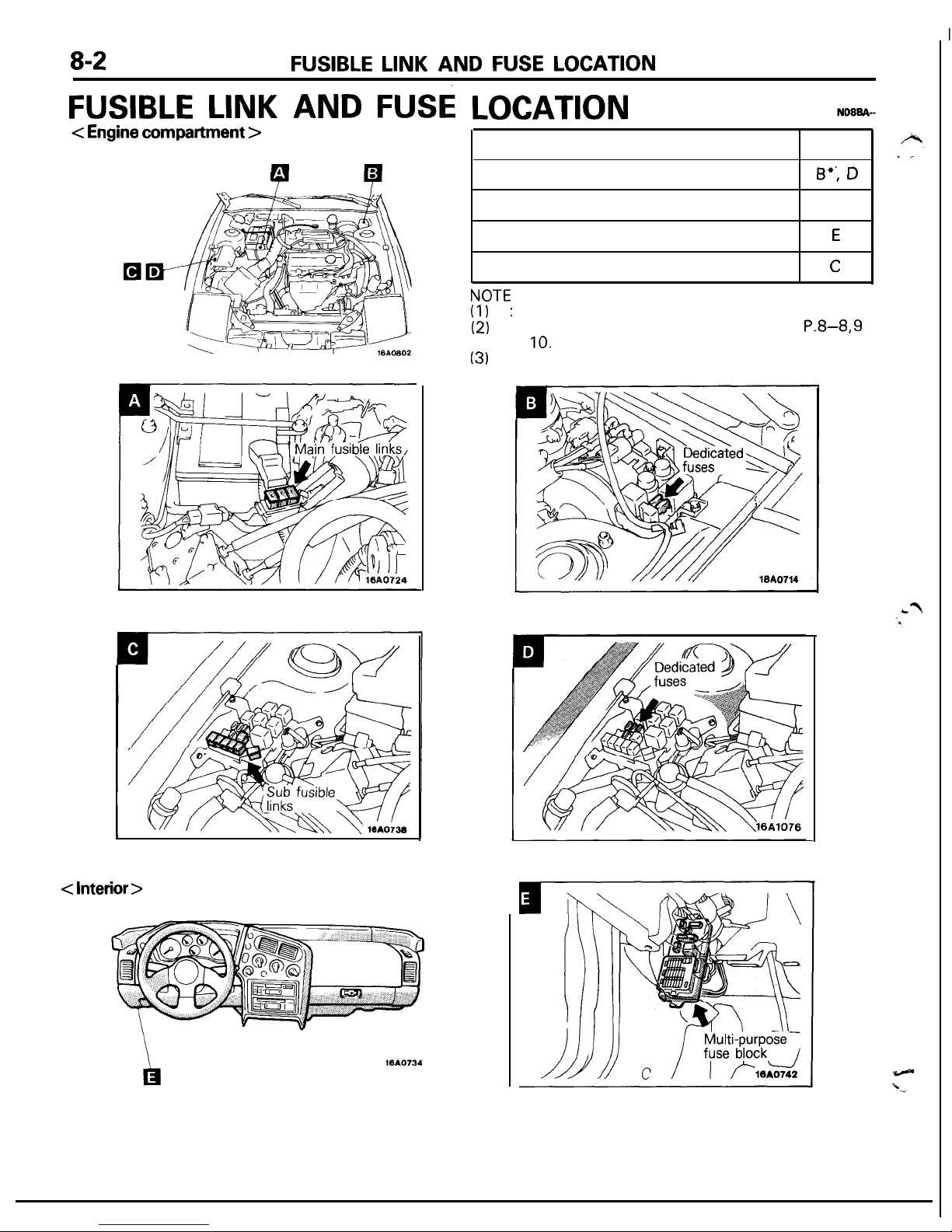
FUSIBLE LINK AND FUSE
LOCATION
< Engine compartment >
1
P
P
:
< Interior >
Name
Dedicated fuses
Main fusible links
Multi-purpose fuse block
Sub fusible links
.
a--r
Symbol
0”; D
A
E
C
NVIE
(1)
l
:
Air conditioner equipped models.
(2)
For details of fusible link and fuse, refer to
P.8-8, 9
and
10.
(3)
The “Name” column is arranged in alphabetical order.
Page 3
INSPECTION TERMINAL LOCATION
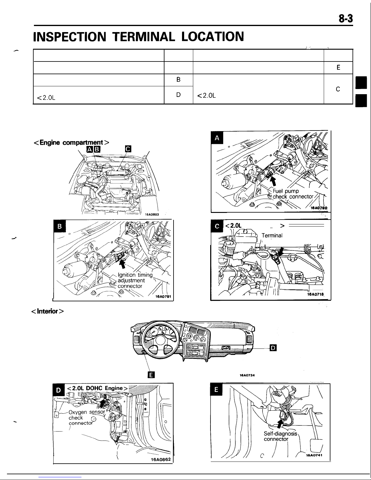
INSPECTION TERMINAL LOCATION
:’
1
.A-
Name
Symbol
Name
Symbol
Fuel pump check connector
A
Self-diagnosis connector.
E
Ignition timing adjustment connector
B
Terminal for detecting the engine
Oxygen sensor check connector
revolution speed
C
c2.OL
DOHC Engine>
D
<2.OL
DOHC Engine>
NOTE
The “Name” column is arranged in alphabetical order.
3
< Engine
compartment
>
I
< Interior >
< 2.OL
DOHC Engine
>
for detecting the
engine revolution speed
\
16A0662
Page 4
8-4
GROUNDING LOCATION
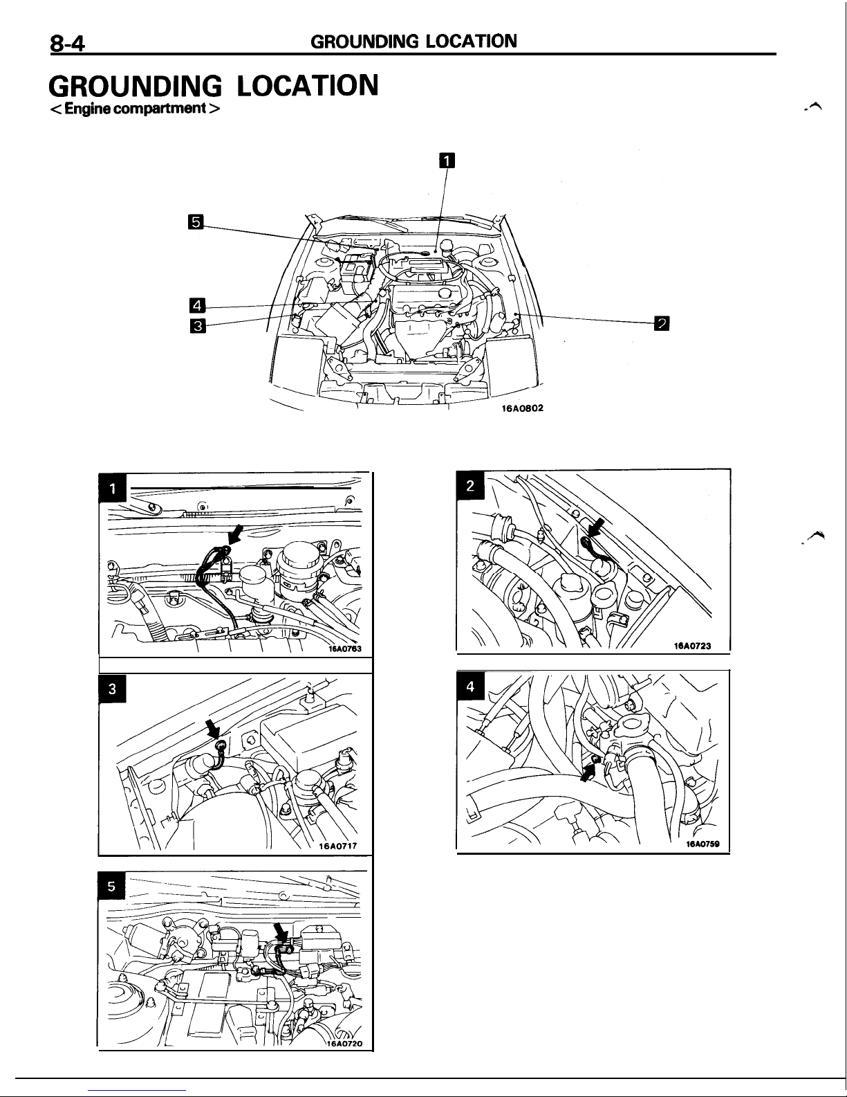
GROUNDING LOCATION
c Engine
compartment
>
Page 5
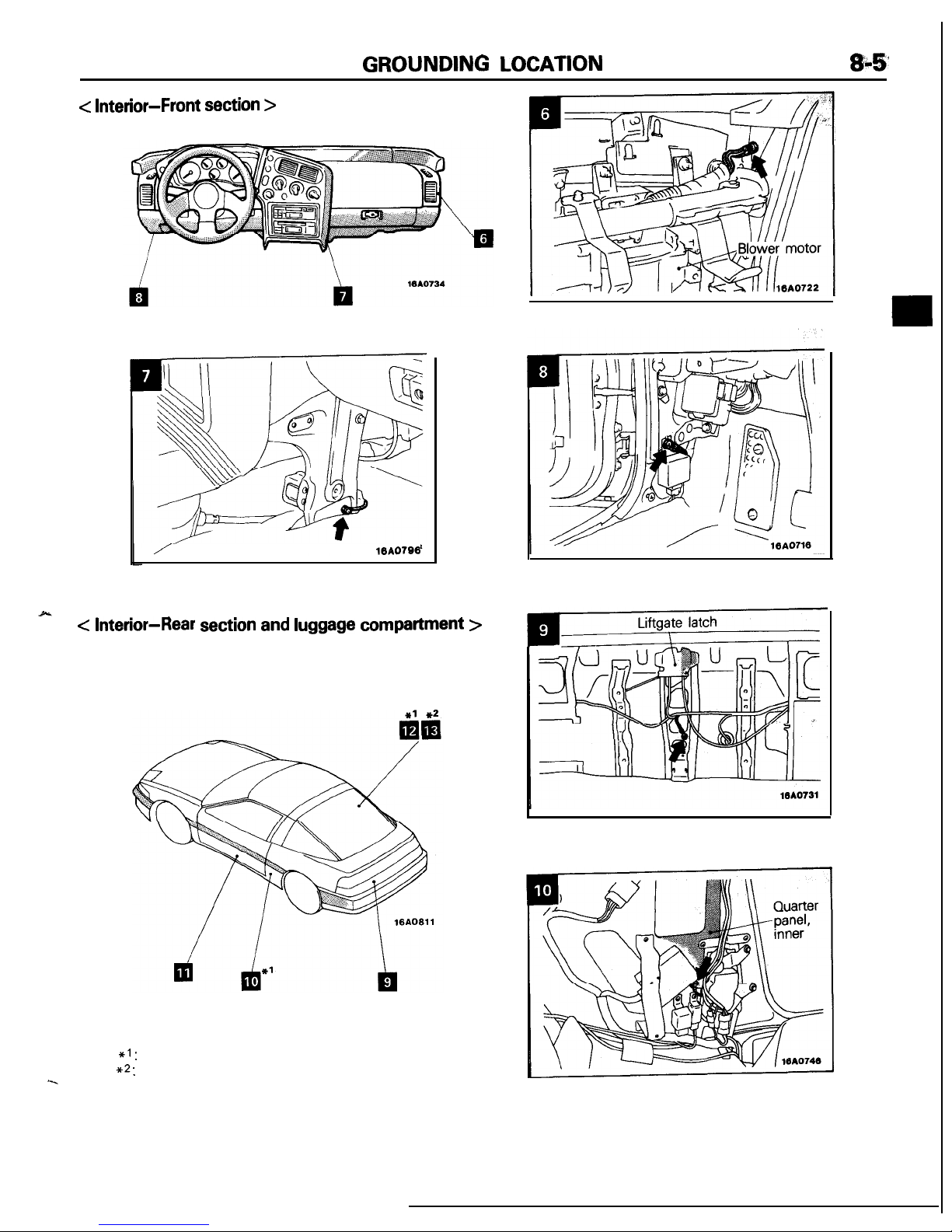
GROUNDING
LOCATION
&;$’
<
Interior-Front
section >
/
10A0786
< Interior-Rear section and luggage compartment >
NOTE
(1)
*I:
Vehicles with automatic seat belt
(2)
**:
Vehicles with ABS
‘-.
Page 6
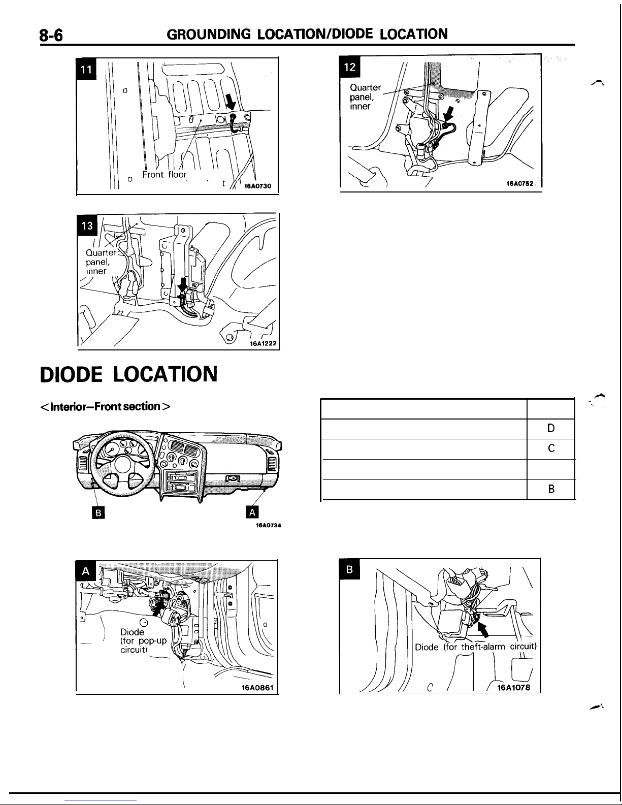
8-6
GROUNDING LOCATION/DIODE
LOCATION
crossmember. front
DIODE LOCATION
< Interior-Front section >
IV\
/
18AO752,
Name
Symbol
Diode (for ABS circuit)
D
Diode (for door ajar-warning circuit)
C
Diode (for pop-up circuit)
A
Diode (for theft-alarm circuit)
B
NOTE
The “Name” column is arranged in alphabetical order.
Page 7
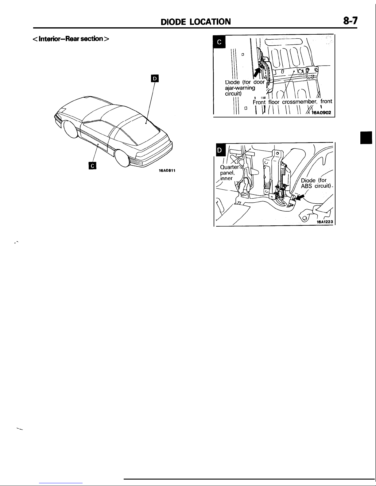
DIODE LOCATION
8-7
<
Interior-Rear
section >
Page 8
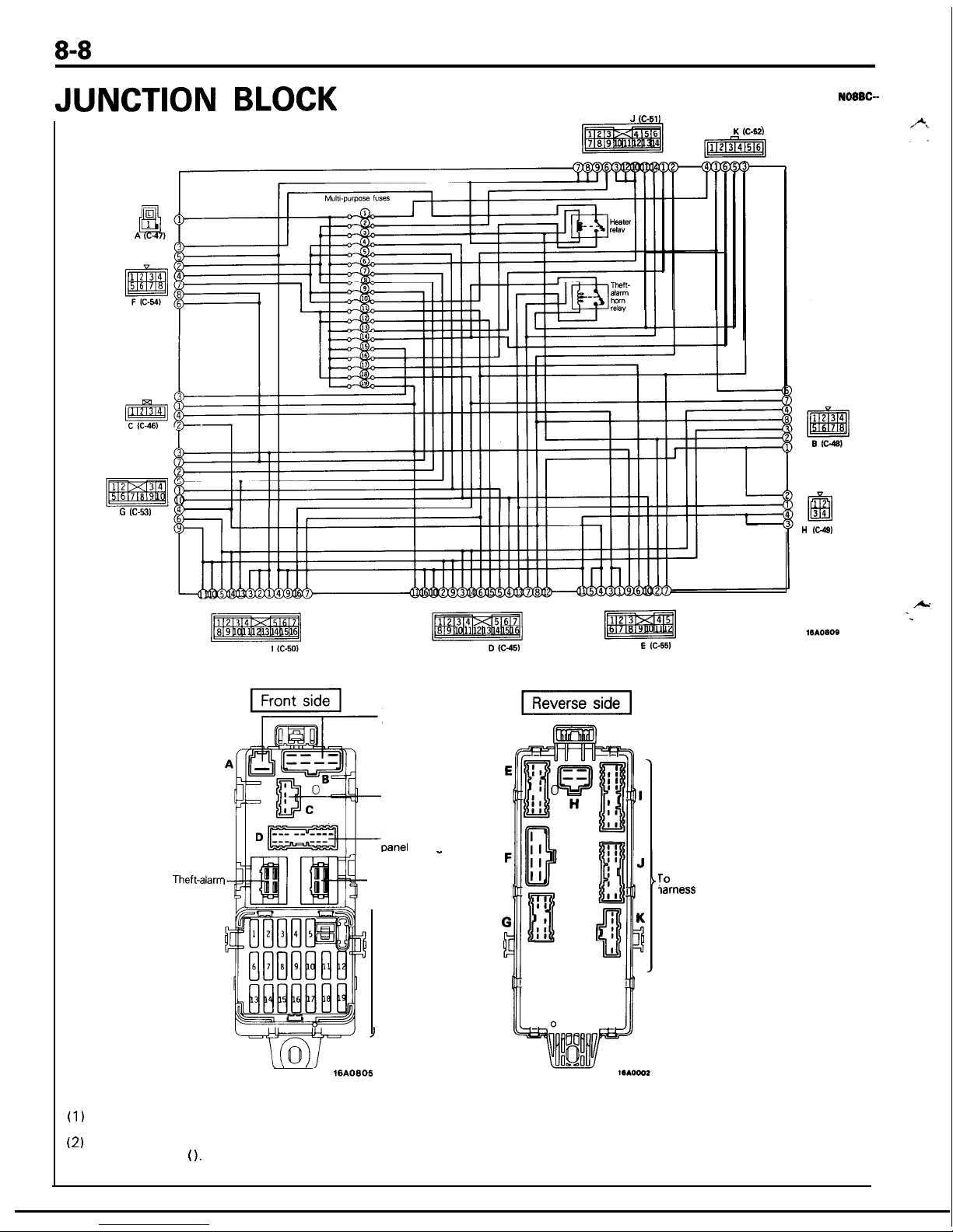
8-8
JUNCTION BLOCK
JUNCTION BLOCK
NOBBC-
G C-531
J (C-511
K IC-52)
Theft-alam
horn relay
To engine compartment
wiring-harness
No connection
To instrument
oanel
wiring
7
1610805
harness
-
-Heater relay
Fuse block
(multi-purpose
fuses)
To
body wiring
iarness
H GW
Remarks
(1)
Same alphabets in the diagram indicate the counterparts
of connectors.
(2)
Terminals of the harness side connector are indicated in
parentheses (
1.
Page 9
CENTRALIZED JUNCTION
CENTRALIZED JUNCTION
N08BB-
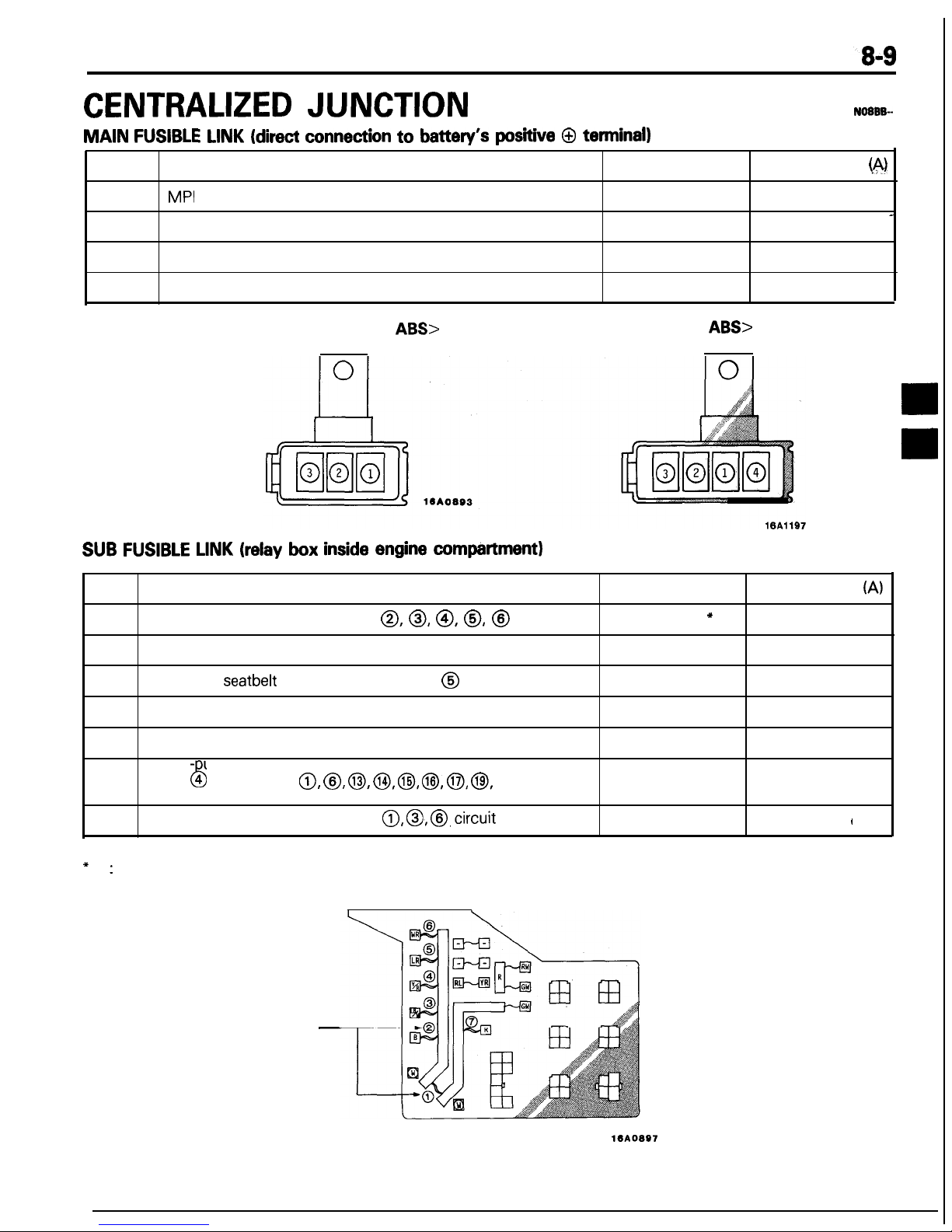
MAIN
FUSIBLE LINK (direct connection
to
battery’s positive 0 terminal)
No.
Circuit
Housing color Rated capacity
@I
1
MPI
circuit
Blue
20
2
Radiator fan motor circuit
Pink
30
-
3
Ignition switch circuit
Pink
30
4
ABS circuit
Yellow
60
<Vehicles without
ABS>
<Vehicles with
ABS>
SUB FUSIBLE LINK (relay box inside engine compartment)
No.
Circuit
Housing color Rated capacity
(A)
--
1
Alternator circuit, sub fusible link
0, 0, @, 0, @
Black, Blue
*
80, 100”
2
Defogger circuit
Green
40
3
Automatic
seatbelt
circuit, dedicated fuse @ circuit
Pink
30
4 Pop-up circuit, Alternator circuit
Pink
30
5
Power window circuit
Pink
30
6
Multi- 6 urpose fuse 0, @, 0,
@I, 0,
@, 0, @, dedicated
fuse 4 circuit
Green
40
7
Headlight circuit, dedicated fuse 0, 0,
@,circuit
Green
40
(
NOTE
*
:
<Vehicles for Canada>
Sub fusible links
-
lOA
Page 10
CENTRALIZED
JUNCTION
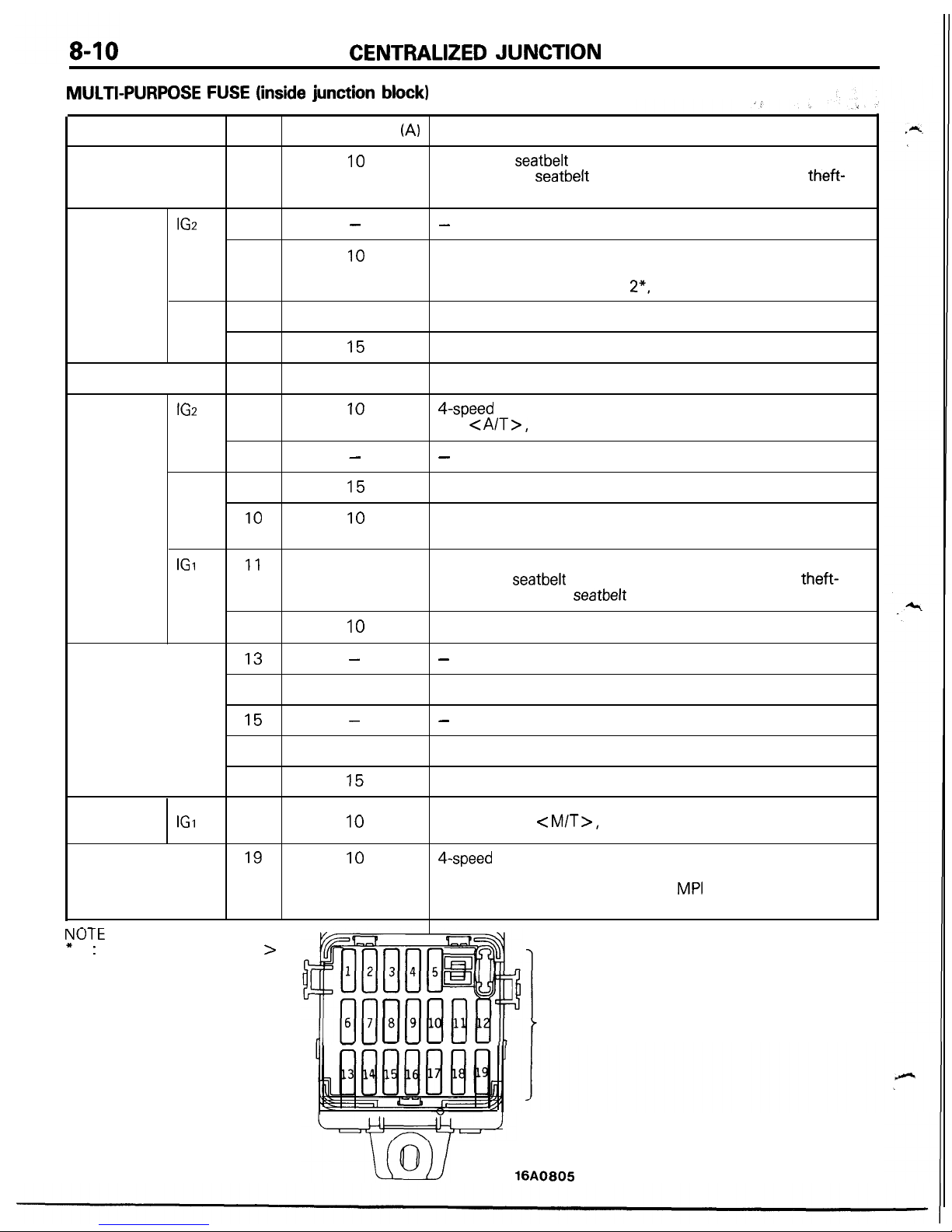
MULTI-PURPOSE FUSE (inside junction block)
Power supply circuit
No.
Rated capacity
(A)
Load circuit
Battery
1
10
Automatic
seatbelt
control unit, key reminder switch, passing
control relay,
seatbelt
warning buzzer, taillight relay, theft-
alarm starter relay
Ignition
switch
IGs
2
3
-
10
-
Air conditioner control unit, air conditioner switch, defogger
timer, heater relay, power window relay, transistor relay*,
daytime running light relay 2*, ABS relay
Battery
Ignition
switch
ACC 4
5
6
IGs
7
8
ACC 9
10
10
15
15
IO
15
IO
Radio
Cigarette lighter, remote controlled mirror
Door lock relay, door lock control unit
4-speed
automatic transaxle control unit, auto-cruise control
unit
<A/T>,
combination meter
-
Intermittent wiper relay, wiper motor, washer motor
Headlight relay, horn, theft-alarm control unit, daytime
running light relay 1 l
IGI
11
10
Auto-cruise control unit, auto-cruise control actuator
automatic
seatbelt
control unit, combination meter, theft-
alarm control unit,
seatbelt
timer*
Battery
Ignition
switch
Battery
IGI
12
13
14
15
16
17
18
19
10
-
10
-
30
15
10
10
Turn-signal and hazard flasher unit
-
Theft-alarm horn relay
-
Blower motor
Stop light
Back-up light
<M/T>,
dome light relay
4-speed
automatic transaxle control unit, dome light,
door-ajar warning light, foot light, ignition key illumination
light, luggage compartment light,
MPI
control unit, radio,
security light, ABS relay
.
.---
NWlt
x
:
<Vehicles for Canada
>
I
Multi-purpose
fuses
16A0805
Page 11
CENTRALIZED
JUNCTION
8-1-I
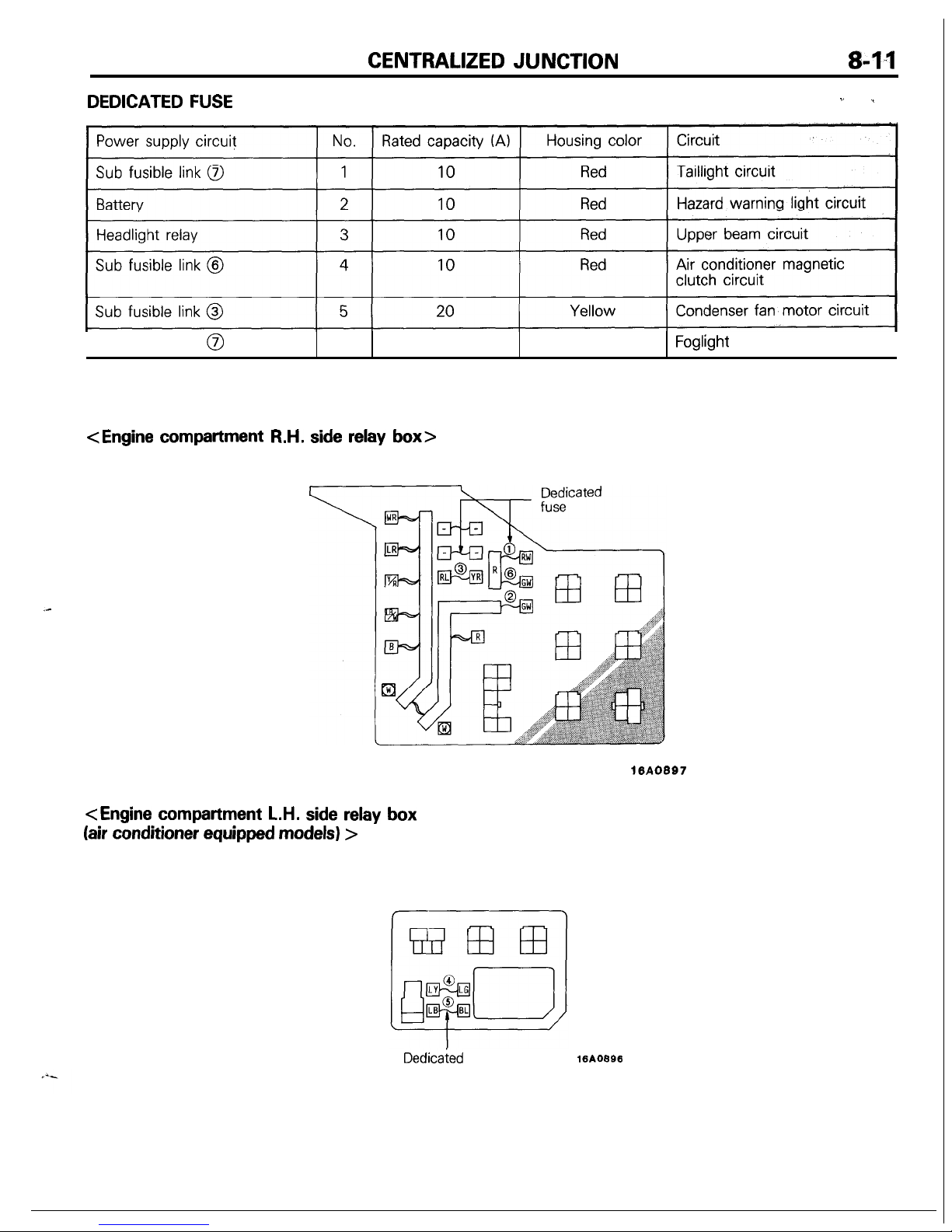
DEDICATED FUSE
,’ >
Sub fusible link @
6
15
Blue
Foglight
circuit
I
<Engine
compartment R.H. side relay box>
16A0897
<Engine
compartment L.H. side relay box
(air conditioner equipped models) >
Dedicaied
fuse
16AOBSS
Page 12
8-12
CENTRALIZED
JUNCTION
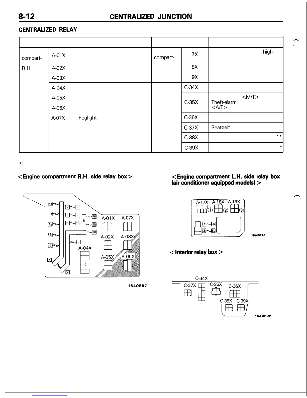
CENTRALIZED RELAY
Classification
Name
Classification
Name
Engine
compart-
A-01X
Taillight relay
Engine
A-l
7X
Condenser fan motor
high-
compart-
low changeover relay
ment
ment
R.H.
side
A-02X
Headlight relay
L.H. side
A-l
8X
Condenser fan motor relay
relay box
relay box
A-03X
Radiator fan motor relay
A-l
9X
Magnetic clutch relay
A-04X
Pop-up motor relay
Interior
c-34x
Door lock relay
relay box
A-05X
Power window relay
Starter relay
<M/T>
c-35x
A-06X
Alternator relay
TJh$;larm
starter relay
A-07X
Foglight
relay
C-36X
Defogger timer
c-37x
Seatbelt
timer*
C-38X
Daytime running light relay
1’
c-39x
Daytime running light relay 2’
NOTE
*:
<Vehicles for Canada>
<Engine
compartment R.H. side relay box>
16A0897
<Engine
compartment L.H. side relay box
(air conditioner equipped models) >
< Interior relay box >
c-34x
Page 13
INSPECTION OF HARNESS CONNECTOR
8-13
INSPECTION OF HARNESS
CONNECTOR
CONTlNUlTY AND VOLTAGE TEST FOR CONNECTOR
Following procedures shall be followed for testing
conti&ty
and
voltage at connector in order to prevent improper contact and
deterioration of waterproof in connector.
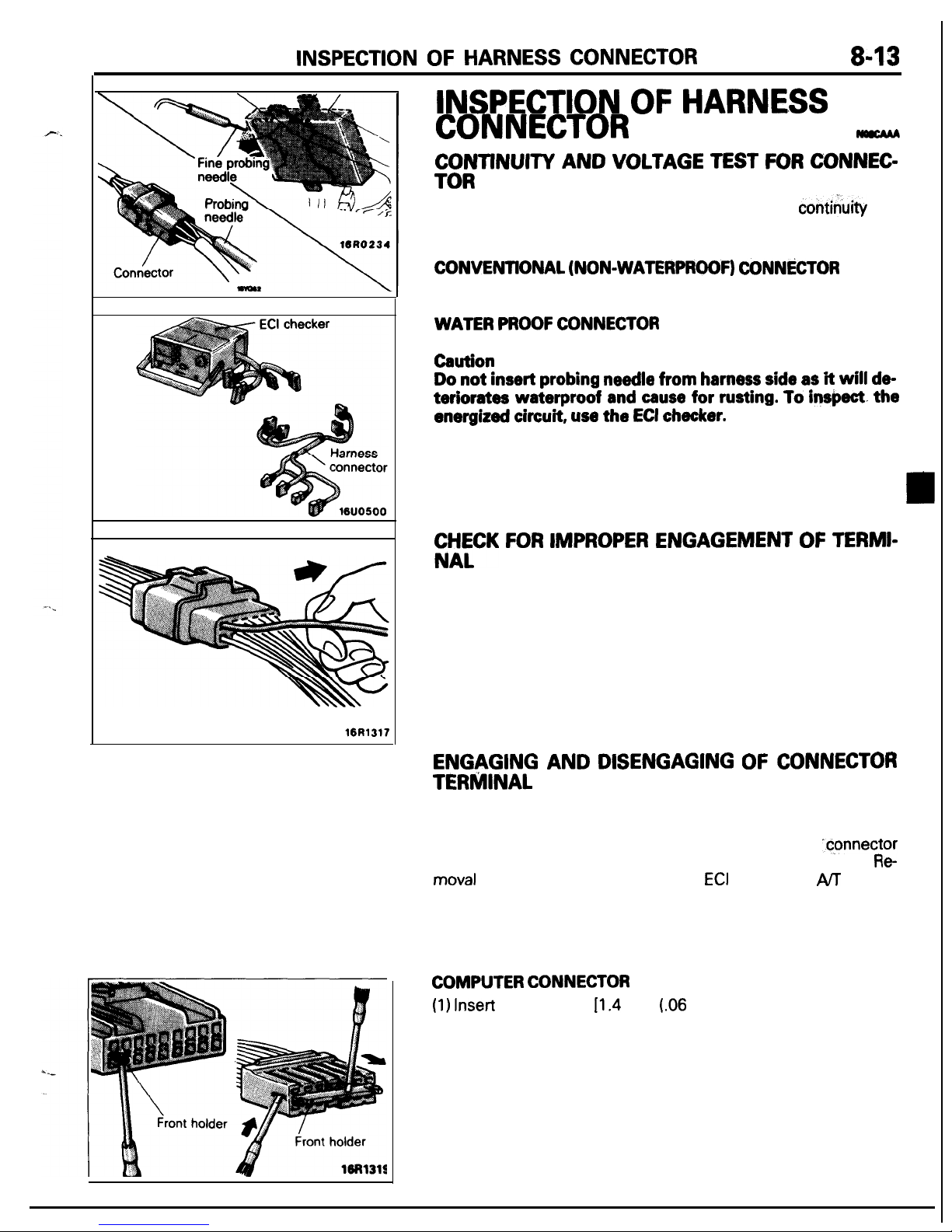
CONVENTlONAL (NON-WATERPROOF)
CONN&TOR
Check shall be done by inserting a probing needle from harness
side.
WATER PROOF CONNECTOR
Caution
Do not insert probing needle from harness side as
it will
de-
terlorates waterproof and cause for rusting. To Inspect.
the
energized circuit, use
the
ECI checker.
flCK FOR IMPROPER ENGAGEMENT OF TERMI-
When terminal stopper of connector is out of order, engagement
of male and female terminals becomes improper even when connector itself is engaged perfectly and terminal sometimes slips out
to rear side of connector. Ascertain, therefore, that each terminal
does not come off connector by pulling each harness wire.
ENGAGING AND DISENGAGING OF CONNECTOR
TERMINAL
Connector which gives loose engagement shall be rectified by
removing female terminal from connector housing and raise its
lance to establish securer engagement. Removal of
“cpnnector
housing and raise its lance to establish securer engagement.
Re
moval
of connector terminal used for
ECI
and ELC 4
AIT
control
circuit shall be done in the following manner.
COMPUTER CONNECTOR
(1) Insert
screwdriver
Il.4
mm
(.06
in.) width] as shown in the
figure, disengage front holder and remove it.
Page 14
8-14
INSPECTION OF HARNESS CONNECTOR
Housing lance
16R1321
Needle
16R1322
I
Housing lance
16R1323
24
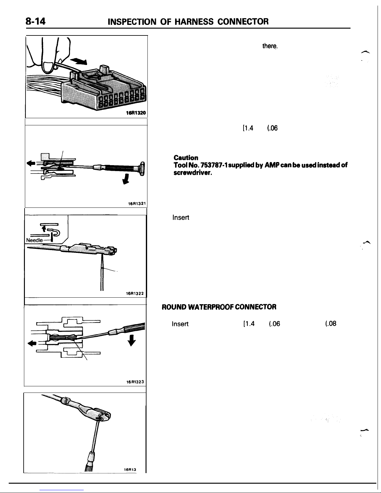
(2) Insert harness of terminal to be rectified deep into connector
from harness side and hold it
there.
(3)
Insert tip of screwdriver
[1.4
mm
(06
in.) width] into connector
in a manner as shown in the figure, raise housing lance slightly
with it and pull out harness.
Caution
Tool No.
753787-l
supplied by
AMP
can be used instead
of
screwdriver.
(4)
Insert
needle through a hole provided on terminal and raise
contact point of male terminal.
ROUND WATERPROOF CONNECTOR
(1) Remove waterproof cap by using a screwdriver.
(2)
Insert
tip of screwdriver
[1.4
mm
(.06
in.) or 2.0 mm
(.08
in.)
width] into connector in a manner as shown in the figure, raise
housing lance slightly with it and pull out harness.
(3) Insert screwdriver through a hole provided on terminal and
raise contact point of male terminal.
Page 15
INSPECTION OF HARNESS CONNECTOR
8-15
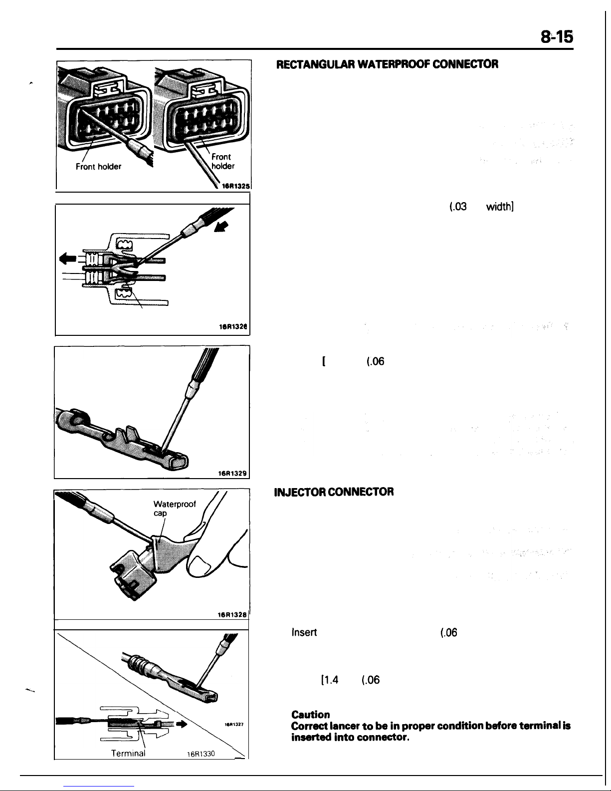
RECTANGULAR WATERPROOF CONNECTOR
(1) Disengage front holder by using a screwdriver and remove it.
Housing lance
16R132d
16R1329
16R1328
Termlnai
lance
16Rl330
\
-
(2)
Insert tip of screwdriver (“0.8 mm
(03
in.)
width]
into connec-
tor in a manner as shown in the figure, push it lightly to raise
housing lancer and pull out harness.
l
lf right size screwdriver is not available, convert a conven-
tional driver to suit the size.
(3)
Press contact point of male terminal down by holding a screwdriver [ 1.4 mm
(06
in.) width] in a manner as shown in the
figure.
INJECTOR CONNECTOR
(1) Remove waterproof cap.
(2)
Insert
tip of screwdriver (1.4 mm
(.06
in.) width] into connector
in a manner as shown in the figure, press in terminal lance and
pull out harness.
(3)
Press contact point of male terminal down by holding a screw-
driver
[1.4
mm
(.06
in.) width] in a manner as shown in the
figure.
Caution
Correct lancer
to be in
proper condition before terminal is
inserted into connector.
Page 16

8-16
TROUBLESHOOTING
TROUBLESHOOTING
The most important point in troubleshooting is to determine “Probable Causes”. Once the probable
causel’&
determined, parts to be checked can be limited to those associated with such probable causes. Therefore,
Uhnec-
essary
checks can be eliminated. The determination of the probable causes must be based on ‘B
th$oqgn! ,b
supported by facts and must not be based on intuition only.
.- I
,
1
i. ,._“‘I. ,,
TROUBLESHOOTING STEPS
If an attempt is made to solve a problem without going through correct steps for troubleshooting, the problem
symptoms could become more complicated, resulting in failure to determine the causes correctly and making
incorrect repairs. The four steps below should be followed in troubleshooting.
1
Observation of Problem Symptoms
I
2 Determination of Probable Causes
0
Checking
of
Parts Associated
with
Troubleshooting is carried out by making step by step checks until
3
Probable Causes and Determination
I
the true cause is found. Always go through the procedures con-
of Faulty Parts
sidering what check is to be made where for the best results.
4 Repair and Confirmation
Observe the symptom carefully. Check if there are also other
problems.
In determining the probable causes, it is necessary to check the
wiring diagram to understand the circuit as a system. Knowledge
of switches, relays and other parts is
necessaty
for accurate determination. The causes of similar problems in the past must be
taken into account.
After the problems are corrected, be sure to check that the system operates correctly. Also check that new problems have not
been caused by the repair.
INFORMATION FOR DIAGNOSIS
This manual contains the cable diagrams as well as the individual circuit drawings, operational explanations,
and troubleshooting hints for each component required to facilitate the task of troubleshooting. The
information is compiled in the following manner:
(1) Cable diagrams show the connector positions, etc., on the actual vehicle as well as the harness path.
(2) Circuit drawings show the configuration of the circuit with all switches in their normal positions.
(3) Operational explanations include circuit drawings of voltage flow when the switch is operated and how
the component operates in reaction.
(4) Troubleshooting hints include numerous examples of problems which might occur, traced backward in a
common-sense manner to the origin of the trouble. Problems whose origins may not be found in this
manner are pursued through the various system circuits.
NOTE
Components of
ECI,
ETACS. ECS, etc. with ECU do not include 3 and 4 above. For this information, refer
to a manual which includes details of these components.
Page 17
-.
Changeover knob
16BO225
16D0226
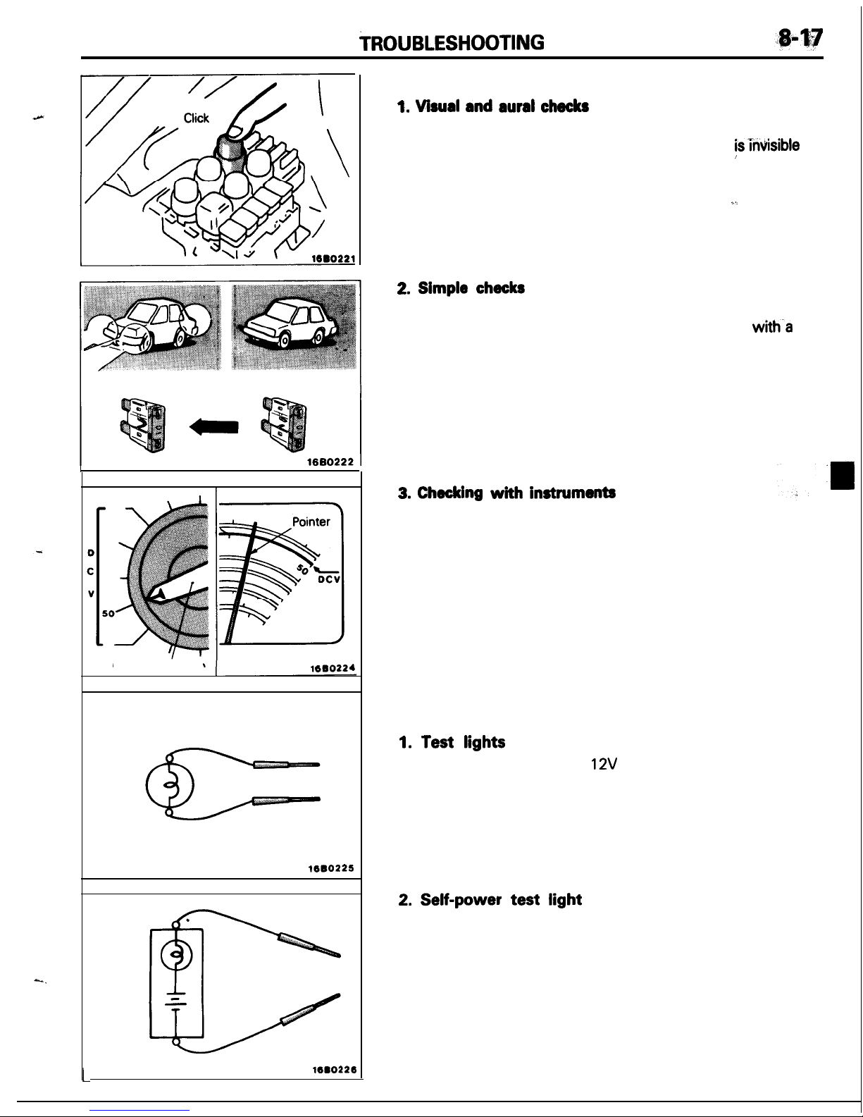
INSPECTION
1. Visual and aural checks
Check relay operation, blower motor rotation, light illumination, etc. visually or aurally. The flow of current
is’invisible
but
can be checked by the operation of the parts.
’
I.
2. Slmple checks
For example, if a headlight does not come on and a faulty fuse
or poor grounding is suspected, replace the fuse with.a new
one or ground the light to the body by a jumper wire to determine which part is responsible for the problem.
3. Checking
with
instruments
Use an appropriate instrument in an adequate range and read
the indication correctly. You must have sufficient knowledge
and experience to handle instruments correctly.
INSPECTION INSTRUMENTS
In inspection, make use of the following instruments.
1. Test
lights
A test light consists of a
12V
bulb and lead wires. It is used
to check voltages or shortcircuits.
2.
Self-power test light
A self-power test light consists of a bulb, battery and lead
wires connected in series. It is used to check continuity or
grounding.
L
Page 18
8-18
TROUBLESHOOTING
16BO227
Ground T
Normal
open
(NO)
type
OFF ON
’
ill&
-//j
Current does not flow
Current flows
1
Current flows
)
Current does
n;;I;Is
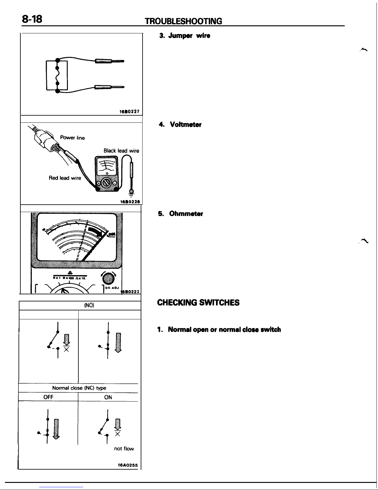
3. Jumper
wire
A jumper wire is used to close an open circuit. Never use one
to connect a power supply directly to a load.
4.
Voltmeter
A voltmeter is used to measure the circuit voltage. Normally,
the positive (red lead) probe is applied to the point of voltage
measurement and the negative (black lead) probe to the body
ground.
5. Ohmmeder
An ohmmeter is used to check continuity or measure resistance of a switch or coil. If the measuring range has been
changed, the zero point must be adjusted before measurement.
CHECKING SWITCHES
In a circuit diagram, a switch is represented by a symbol and in the
idle state.
1.
Normal open or normal close switch
Switches are classified into those which make the circuit open
and those which make the circuit closed when off.
Page 19

TROUBLESHOOTING
849
16A0253
Coil
Iron
piece
.
Cover
Spring
Iron
core
Contact
1600231
Power supply
I I
10AO254
Current does not flow
I
I
Normal
open
(NO) type
Energized
state
nml
a
Current flows
16AO250
2. SWITCH
CONNECTION
This figure illustrates a complex switch. The continuity
between terminals at each position is as indicated in the
table below.
,.
-stage
I-
-.- -‘-J’-
‘L
NOTE
o---O
denotes continuity between terminals.
CHECKING RELAYS
1. When current flows through the coil of a relay, its core is
magnetized to attract the iron piece, closing (ON) the contact
at the tip of the iron piece. When the coil current is turned off,
the iron piece is made to return to its original position by a
spring, opening the contact (OFF).
,.
2.
By using a relay, a heavy current can be turned on and off
by a switch of small capacity. For example, in the circuit
shown here, when the switch is turned on (closed), current
flows to the coil of the relay. Then, its contact is turned on
(closed) and the light comes on. The current flowing at this
time to the switch is the relay coil current only and is very
small.
3.
The relays may be classified into the normal open type and the
normal close type by their contact construction.
NOTE
The deenergized state means that no current is flowing
through the coil and the energized state means that current is
flowing through the coil.
Page 20
8-20
TROUBLESHOOTING
Normal close
(NC) type
Deenergized
state
Energized state
i
I
Current flows
Current does not flow
MAO257
1680235
State of fuse blown due to overcurrent
1680237
State of fuse blown due to thermal fatigue
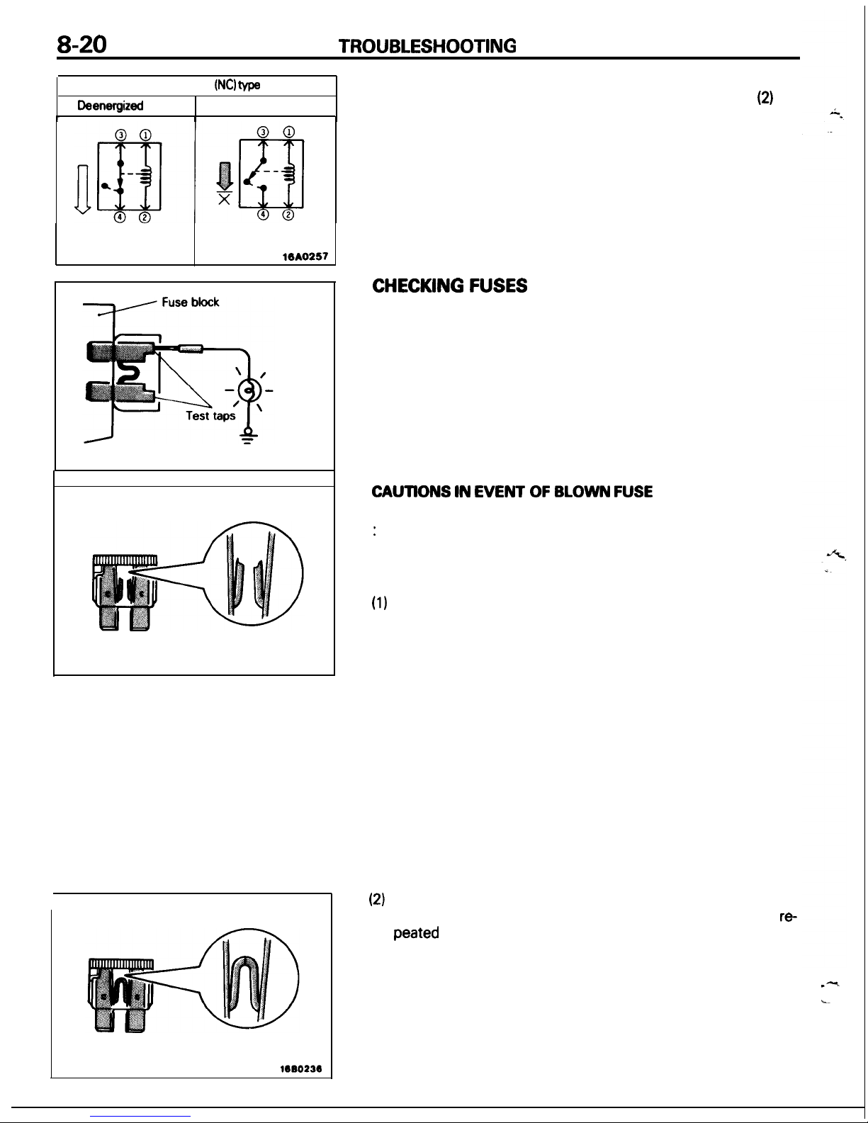
When a normal close type relay as illustrated here is checked,
there should be continuity between terminals (1) and
(2)
and
between terminals 3 and 4 when the relay is deenergized,
and
the continuity should be lost between terminals 3 and 4
when the battery voltage is applied to the terminals 1 and 2.
A
relay can be checked in this manner and it cannot be determine if a relay is okay or faulty by checking its state only when
it is deenergized (or energized).
CHECKING FUSES
A blade type fuse has test taps provided to allow checking of
the fuse itself without removing it from the fuse block. The
fuse is okay if the test light comes on when its one lead is
connected to the test taps (one at a time) and the other lead is
grounded. (Change the ignition switch position adequately so
that the fuse circuit becomes live.)
CAUTlONS IN EVENT OF BLOWN FUSE
When a fuse is blown, there are two probable causes as follows
:
One is that it is blown due to flow of current exceeding its rating.
The other is that it is blown due to repeated on/off current flowing
through it. Which of the two causes is responsible can be easily
determined by visual check as described below.
(1)
Fuse blown due to current exceeding rating
The illustration shows the state of a fuse blown due to this
cause. In this case, do not replace the fuse with a new one
hastily since a current heavy enough to blow the fuse has
flowed through it. First, check the circuit for shorting and
check for abnormal electric parts. Only after the correction of
such shorting or parts, fuse of the same capacity should be
used as a replacement. Never use a fuse of lager capacity than
the one that has blown. If such a fuse is used, electric parts or
wirings could be damaged before the fuse blows in the event
an overcurrent occurs again.
(2)
Fuse blown due to repeated current on/off
The illustration shows the state of a fuse blown due to
re
peated
current on/off. Normally, this type of problem occurs
after fairly long period of use and hence is less frequent than
the above type. In this case, you may simply replace with a
new fuse of the same capacity.
Page 21
TROUBLESHOOTING
8-21
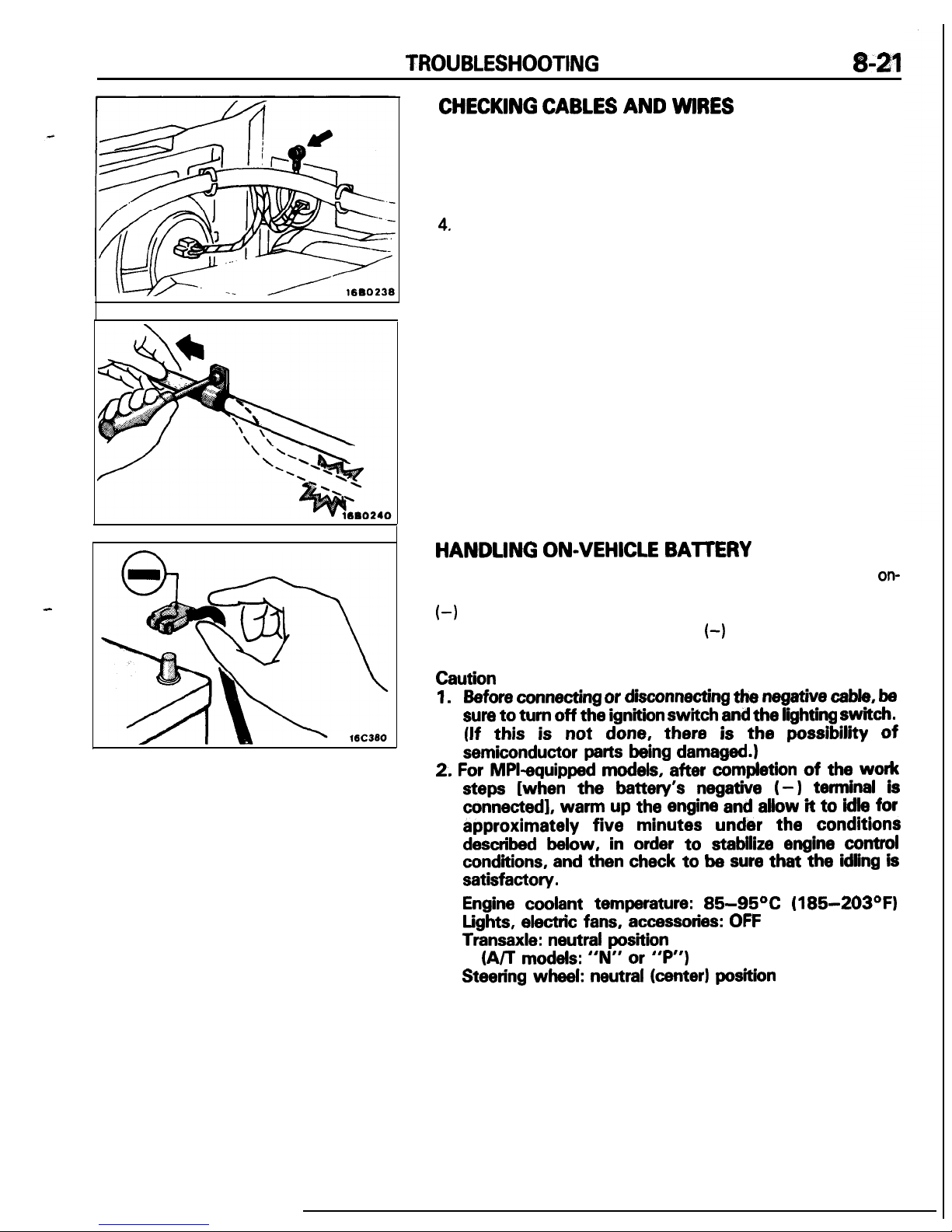
CHECKING CABLES AND WlRES
1.
Check connections for looseness, rust and stains.
2.
Check terminals and wires for corrosion by battery electrolyte,
etc.
3.
Check terminals and wires for open circuit or impending open
circuit.
4.
Check wire insulation and coating for damage, cracks and de
grading.
5. Check conductive parts of terminals for contact with other
metallic parts (vehicle body and other parts).
6.
Check grounding parts to verify that there is complete continuity between attaching bolt(s) and vehicle body.
7. Check for incorrect wiring.
8.
Check that wirings are so clamped as to prevent contact with
sharp corners of the vehicle body, etc. or hot parts (exhaust
manifold, pipe, etc.).
9.
Check that wirings are clamped firmly to secure enough clear-
ance from the fan pulley, fan belt and other rotating or moving
parts.
.
10. Check that the wirings between the fixed parts such as the
vehicle body and the vibrating parts such as the engine are
made with adequate allowance for vibrations.
HANDLING ON-VEHICLE BATTERY
When checking or servicing does not require power from the
on-
vehicle battery, be sure to disconnect the cable from the battery
(-)
terminal. This is to prevent problems that could be caused by
shorting of the circuit. Disconnect the
(-)
terminal first and recon-
nect it last.
Caution
1.
Before connecting or disconnecting
the
negative cable, be
sure
to
turn off
the
ignition
switch
and
the
lighting
switch.
(If this is not done, there is the
possibility
of
semiconductor parts being damaged.)
2.
For MPI-equipped models, after completion
of
the work
steps [when
the
battery’s negative f-1 terminal is
connected],
warm up
the engine and allow it
to
idle for
approximately five minutes
under
the conditions
described below, in order to stabilize engine control
conditions, and then check to be sure
that the
idling is
satisfactory.
Engine coolant temperature: B5-95% (185-203OF)
Lights, electric fans, accessories: OFF
Transaxle: neutral position
(A/T
models: “N” or “P”)
Steering wheel: neutral (center) position
Page 22
8-22
TROUBLESHOOTING
Power supply
10A0200
Power supply
(Remove the fuse
iii
lllumlnation
light
T
16A0502
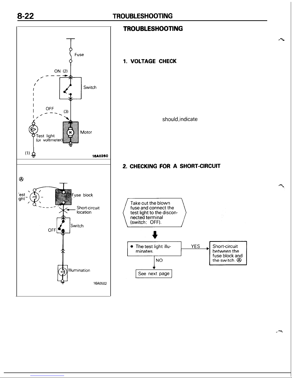
TROUBLESHOOTING
A circuit consists of the power supply, switch, relay, load, ground,
etc. There are various methods to check a circuit including an
overall check, voltage check, shortcircuit check and continuity
check. Each of these methods is briefly described in the following.
1. VOLTAGE CHECK
(1) Ground one lead wire of the test light. If a voltmeter is
used instead of the test light, ground the grounding side
lead wire.
(2) Connect the other lead wire of the test light to the
power side terminal of the switch connector. The test
light should come on or the voltmeter should indicate a
voltage.
(3) Then, connect the test light or voltmeter to the motor
connector. The test light should not come on, or the
voltmeter
should.indicate
no voltage. When the switch
is turned on in this state, the test light should come on,
or the voltmeter should indicate a voltage, with motor
starting to run.
(4) The circuit illustrated here is normal but if there is any
problem such as the motor failing to run, check voltages
beginning at the connector nearest to the motor until
the faulty part is identified.
2. CHECKING FOR
A
SHORT-CIRCUIT
Because the fuse has blown, it is probable that there is a
short-circuited circuit. Follow the procedures below to
narrow down the short-circuit location.
Page 23
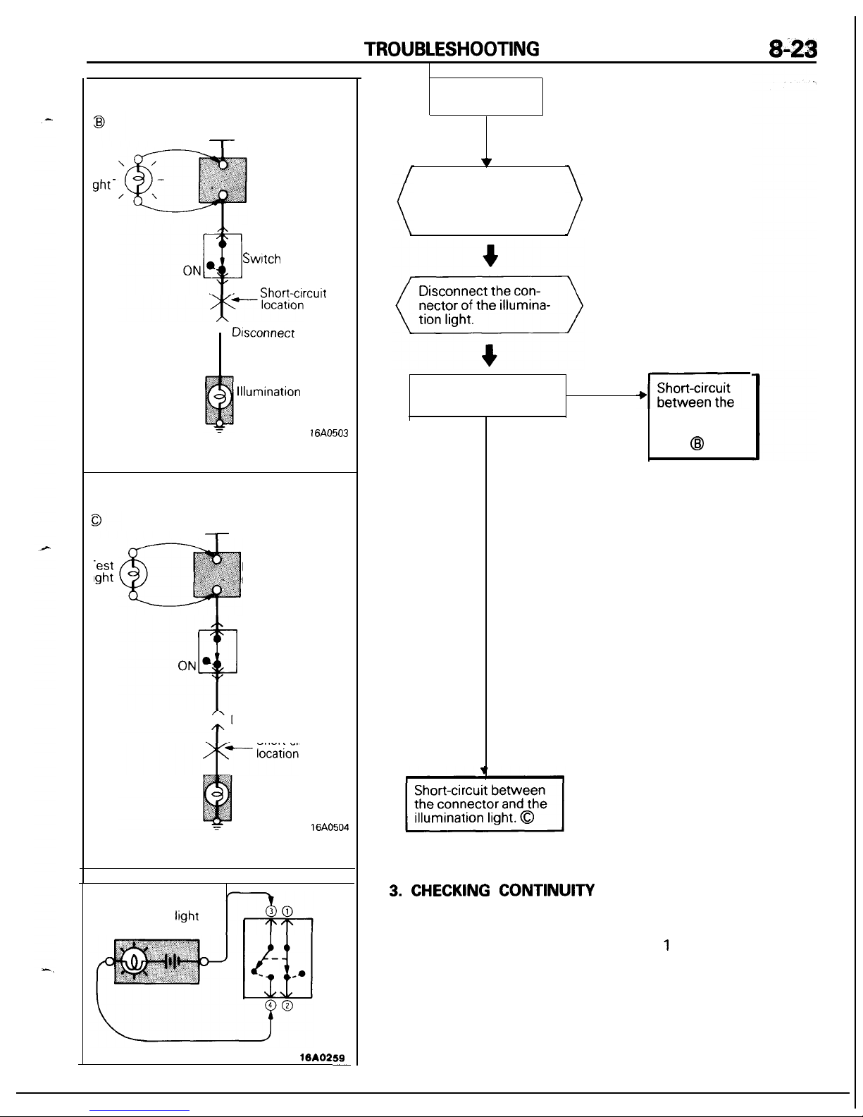
TROUBLESHOOTING
8-28
Power supply
l-
‘est
ght-
Fuse block
(Remove the fuse
Switch
Short-clrcutt
Disconnect
the load
llluminatlon
light
16A0503
Power supply
-
-est
lght
Fuse block
(Remove the
fuse.)
Switch
Disconnect the load
Short-circuit
Illumination
light
16A0504
Self power test light
(or ohmmeter)
16A0259
-
Continued from
previous page
w
Switch ON the switch.
(The test light illumi-
nates but the illumination light does not.)
l
The test light re-
mains illuminated.
YES
+B
I
I
NO
switch and the
illumination
light.
@I
3. CHECKING
CONTINUITY
(1) When the switch is in the OFF position, the self power
test light should come on or the ohmmeter should read
0 ohm only when the terminals 1 and 2 are interconnected.
(2) When the switch is the ON position, the self power test
light should come on or the ohmmeter should read 0
ohm only when the terminals 3 and 4 are interconnected.
Page 24
8-24
NOTES
Page 25
CONFIGURATION
DIAGRAMS
CONTENTS
NOWA -.
Dash Panel ...................................................... 36
Engine
Compartment
<2.OL DOHC
Engine
(Turbo)>
.....................
32
Engine and Transaxle
<1.8L Engine>
........
34
How to
Read
Configuration Diagrams..
......
27
Engine and Transaxle
<2.OL DOHC
Engine>
....................................
35
Instrument
Panel and Floor Console
.......... 39
Engine
Compartment
<1.8L
Engine>
.........
28
Interior
.............................................................
40
Engine
Compartment
Overall
Configuration
Diagram ..................... 26
<2.OL DOHC Engine
(Non-Turbo)>
............. 30
Page 26
CONFIGURATION DIAGRAMS
- Overall Configuration Diagram
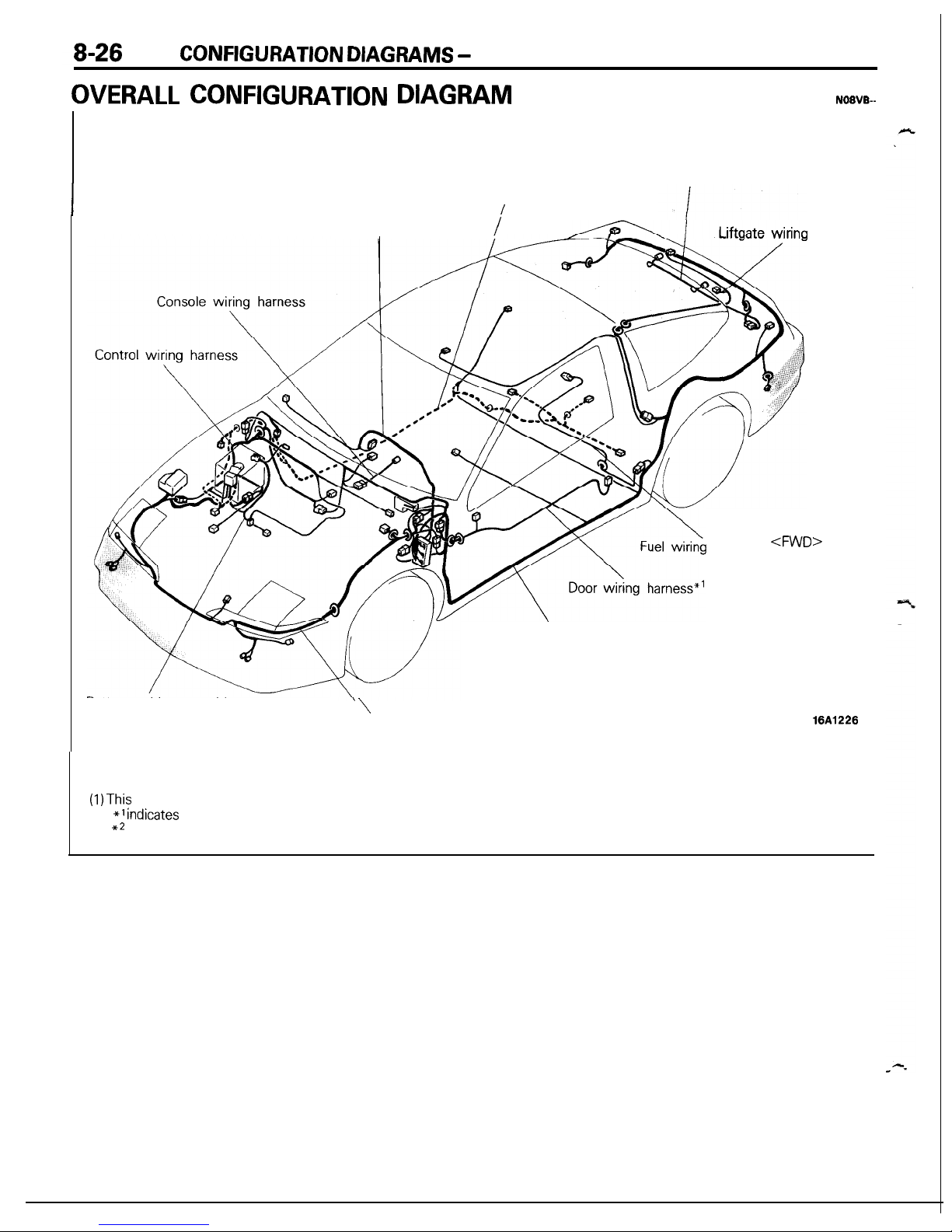
OVERALL CONFIGURATION DIAGRAM
NOIVB-
License plate light
wiring harness
ABS wiring harness**
/
Instrument panel wiring harness
/
harness
harness
<FWD
Body wiring harness
>
Battery cable
assembly
\
Engine room wiring harness
NOTE
(I)
This
illustration shows only the major wiring harness.
(2) *l
Indicates
also equipped at the right side.
(3) *2 indicates vehicles with ABS.
16A1226
Page 27
CONFIGURATION DIAGRAMS
-
How to Read Configuration Diagrams 8-27
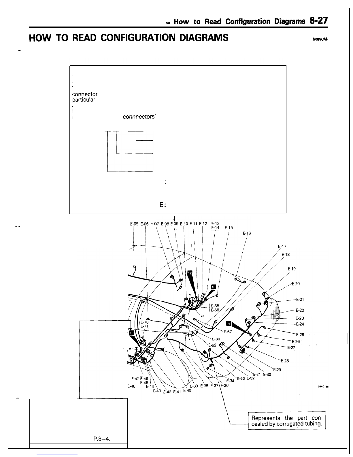
HOW TO READ CONFIGURATION DIAGRAMS
NosvcAH
I.
The wiring diagrams are prepared in such a way that the arrangement of connectors for each vehicle, and the
routing of each harness, can be easily understood for each individual wiring section.
Indicates the connector number.
The connector number used is the same number as that used for circuit diagrams;
these numbers facilitate the location of the connector positions.
The alphabet letter used as the prefix represents the wiring section in which that
sonnector
is used; subsequent numerals make up the number that indicates
oarticular
characteristics of that individual connector. As a general rule, numbers are
assigned clockwise around the wiring diagram.
Vote that, if there is a concentration of connectors with the same form (same
lumber of pins), the connnectors’ colors are noted in order to facilitate identification,
Example: A-l 2 (Black)
Connector color
Number indicating the connector’s
characteristics (series number)
Symbol indicating wiring section
location of the connector
A : Engine compartment
B: Engine and transaxle
C: Dash panel
D: Instrument panel and floor console
E :
Interior
I
E-05 E-06 E-07 E-08 E-09 E-10 E-11 E-12 E-13
1)
\\\~\~'14‘;:"
-\\I
II I
/
/
E-17
E-22
E-23
Indicates ground point.
The ground number used is the
same number as that used for circuit
diagrams; these numbers facilitate
the location of the ground points,
For detailed information concerning
ground points, refer to P.B-4.
Page 28
8-28
CONFIGURATION DIAGRAMS
- Engine Compartment
<1.8L
Engine>
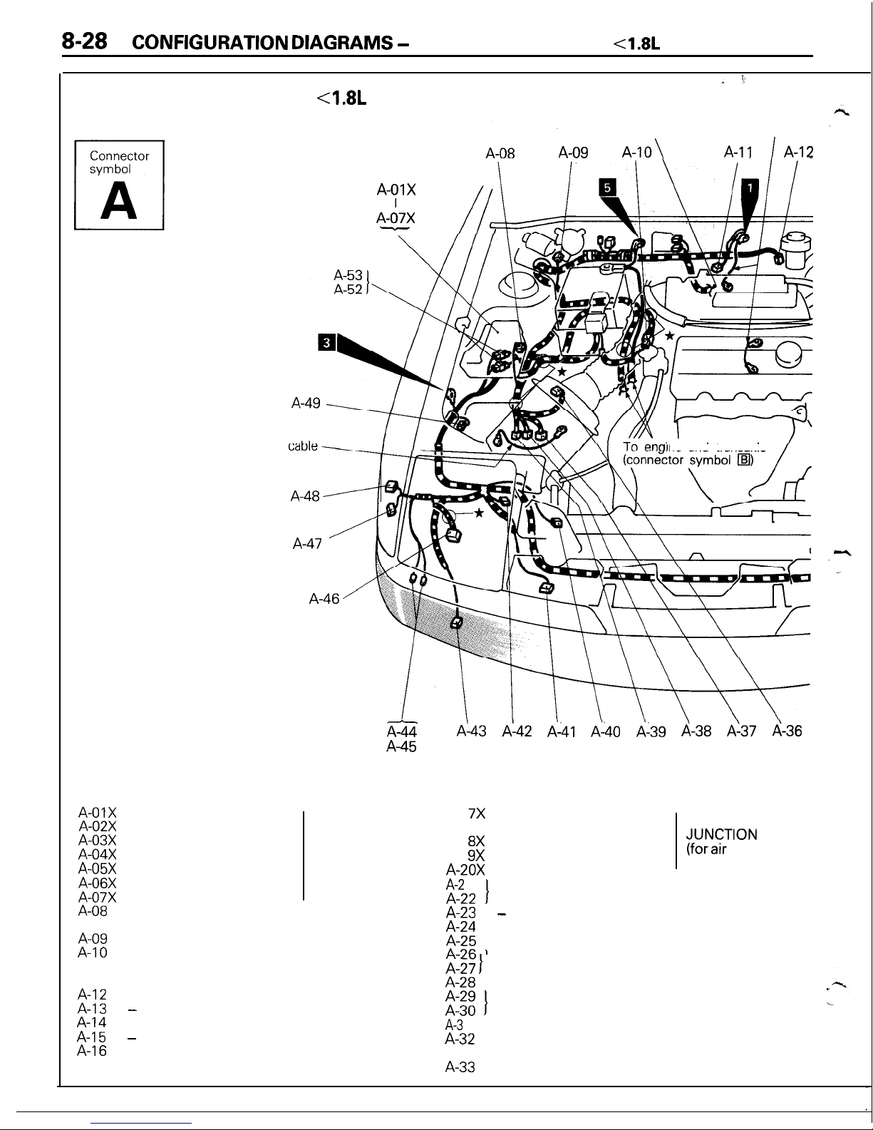
ENGINE COMPARTMENT
4.8L
Engine>
Connector
symbol
3
A
To engine and transaxle ‘Ground
(connector symbol
q
)
cable
A-09
A-10\
A-11
/
A-12
Ground
A-01X
A-02X
A-03X
A-04X
A-05X
A-06X
A-07X
A-08
A-09
Taillight relay
Headlight relay
Radiator fan motor relay
Pop-up motor relay
Power window relay
Alternator relay
Fog light relay
Dual pressure switch
(for air conditioner circuit)
Wiper motor
A-01X
A-d7X
-
ne and transaxle
A-47
iiz
A-45
A-46 ’
Refer to
CENTRALIZED
JUNCTION
A-10
Control wiring harness and battery cable
assembly combination
A-l 1
A-12
Auto-cruise control vacuum pump
Brake fluid level sensor
A-13 -
A-14
Purge control solenoid valve
A-15 A-16
EGR control solenoid valve
(Vehicles for California)
A-43 A-42 A-41 A-40 A-39 A-38 A-37 A-36
A-l
7X
Condenser fan motor
A-l
8X
high-low changeover relay
A-l
9X
Condenser fan motor relay
Magnetic clutch relay
A-20X
Condenser
A-2
1
A-22
t
Air conditioner relay box
A-23 A-24
Washer motor
A-25
A?C 1
Pop-up motor (Left side)
Refer to
CENTRALIZED
?firNaYrTloN
conditioner
circuit)
i$y 1
Front combination light (Left side)
A-28
A-29
Headlight (Left side)
A-30
t
Horn (Left side)
A-3
1
A-32
Fog light (Left side)
Condenser fan motor
(for air conditioner circuit)
A-33
Front turn-signal light (Left side)
Page 29
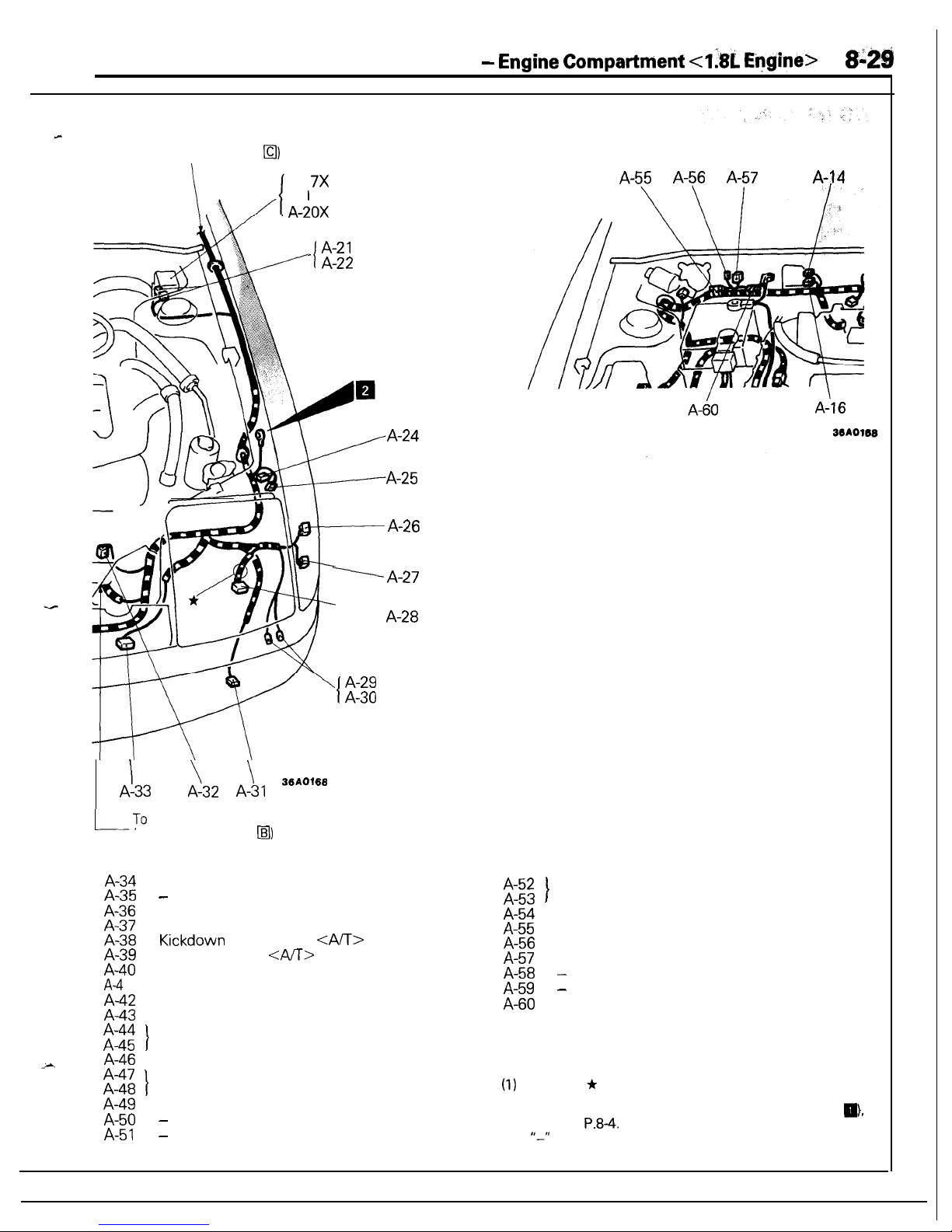
CONFIGURATION DIAGRAMS
- Engine Compartment <I& Engine>
8:gg
To dash panel
(connector symbol
El)
A-l
7X
A-:0X
_ A-21
1
A-22
A-24
A-25
A-26
I
\
\
A-33
A-32 A-31 36A0168
ITo
engine and transaxle
(connector symbol
a)
y
A-27
-------
A-28
1
A-29
A-30
A-34
A-35
A-36
A-37
A-38
A-39
A-40
A-4
1
A-42
A-43
A-44
A-45
>.A
A-46
A-47
A-48
A-49
A-50
A-51
-
Air flow sensor
Automatic transaxle fluid temperature sensor
Kickdown
servo switch
<A/T>
Pulse generator
<AA>
Radiator fan assembly
Front turn-signal light (Right side)
Radiator water level switch
Fog light (Right side)
t
Horn (Right side)
Headlight (Right side)
I
Front combination light (Right side)
Pop-up motor (Right side)
-
-
A-55 A-56 A-57
A-14
A-52
A-53
A-54
A-55
A-56
A-57
A-58
A-59
A-60
t
Control wiring harness and engine
compartment wiring harness combination
Fuel pump check connector
Noise condenser
Defogger relay
-
-
Ignition timing adjustment connector
Remarks
(I) The mark * shows the standard mounting position of
wiring harness.
(2)
For details concerning the ground point ‘(example:
a).
refer to
P.8-4.
(3)
1(-11
means that the connector with code-number is not
used.
Page 30
8-30
CONFIGURATION DIAGRAMS
-
Engine Compartment
<Z.OL
DOHC Engine (Non-Turbo)>
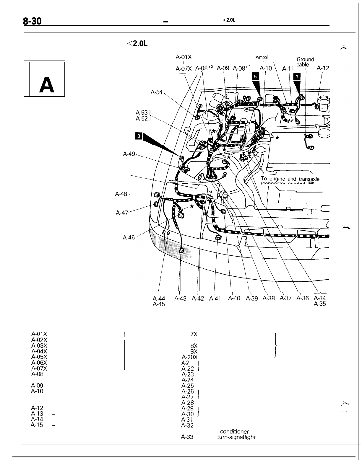
ENGINE COMPARTMENT
<2.OL
DOHC Engine (Non-Turbo)>
Connector
symbol
A
A-01X
A-02X
A-03X
A-04X
A-05X
A-06X
A-07X
A-08
Ground cable
A-47
Taillight relay
Headlight relay
Radiator fan motor relay
Pop-up motor relay
Power window relay
Alternator relay
Fog light relay
Dual pressure switch
(for air conditioner circuit)
\
A-01X
To engine and transaxle
(connector
sympol
q )
Ground
A-&X A-gBx2 A-09 A-08”’
A-IO\
A-11
cab!e
A-12
- I
(connector symbol
q
)
IL-
A-44
A-45
Refer to
CENTRALIZED
JUNCTION
A-09
Wiper motor
A-10
Control wiring harness and battery cable
A-l 1
assembly combination
A-12
Auto-cruise control vacuum pump
Brake fluid level sensor
A-13 A-14
Purge control solenoid valve
A-15 -
A-l 6
EGR control solenoid valve
(Vehicles for California)
A!43 A-142 A-&
A!40
A!39 d-38 d-37 A-36 AZ
A-35
A-l
7X
Condenser fan motor
Refer to
A-l
8X
high-low changeover relay
CENTRALIZED
Condenser fan motor relay
JUNCTION
A-l
9X
Magnetic clutch relay
(for air
A-20X
Condenser
conditioner
A-2
1
I
circuit)
A-22
Air conditioner relay box
A-23
ABS front speed sensor (Left side)
A-24
Washer motor
A-25
Pop-up motor (Left side)
A-26
A-27
I
Front combination light (Left side)
A-28
Headlight (Left side)
A-29
A-30
I
Horn (Left side)
A-3 1
A-32
Fog light (Left side)
Condenser fan motor
A-33
(for air
cond,itioner
circuit)
Front turn-signal
lrght
(Left side)
Page 31

CONFIGURATION DIAGRAMS
-
E
ngine Compartment
<2.OL
DOHC Engine
(Non-Turbo)>
8131
To
dash panel
(connector symbol
fl)
I
,
I
A-l
7X
I
A-21
-
A-22
:\
,
A-23
\
\
WA0172
A-33
A-32
A-31
1
To engine and transaxle
(connector symbol
q
)
A-34
A-35
A-36
A-37
A-38
A-39
A-40
A-4
1
A-42
A-43
A-44
A-45
A-46
A-47
A-48
A-49
A-50
A-51
t
I
A-29
A-30
Hydraulic unit
Air flow sensor
Automatic transaxle fluid temperature sensor
Kickdown
servo switch
<A/T>
Pulse generator
<A/T>
Radiator fan assembly
Front turn-signal light (Right side)
Radiator water level switch
Fog light (Right side)
Horn (Right side)
Headlight (Right side)
Front combination light (Right side)
Pop-up motor (Right side)
-
-
A-55 A-56 A-57
A-14 A-59
A-52
A-53
t
Control wiring harness and engine
compartment wiring harness combination
A-54
A-55
ABS front speed sensor (Right side)
Fuel pump check connector
A-56
Noise condenser
A-57
Defogger relay
A-58 -
A-59
Engine speed adjustment connector
A-60
Ignition timing adjustment connector
A-60
A-116
36AO172
Remarks
(1)
The mark * shows the standard mounting position of
(2)
wiring harness.
For details concerning the ground point (example:
m,
refer to
P.84.
(3)
‘I-”
means that the connector with code-number is not
used.
(4) The wiring indicated by the
*I
symbol is applicable to
vehicles with ABS and the wiring indicated by the
+2
symbol is applicable to vehicles Gthout ABS.
J
Page 32

8-32
CONFIGURATION
DIAGRAMS
-
Engine Compartment
<2.OL
DOHC Engine (Turbo)>
ENGINE
TMENT
<2.OL DOHC Engine
(Turbo)>
A-01X
To engine and transaxle
(connector symbol
ail)
Ground
cabje
A-09 A-O8*3
A-IO
I
Connector
symbol
A-53
A-52
A-5
1
\
Ground
To
‘engine and transaxle
(connector symbol
n
A-43 A!42
A140 d-39 A-38 d-37 A-36
g
A-l
7X
A-l
8X
A-l
9X
A-20X
A-21
A-22
A-23
A-24
Condenser fan motor
I
Refer to
high-low changeover relay
CENTRALIZED
Condenser fan motor relay
JUNCTION
Magnetic clutch relay
(for air
Condenser
conditioner
circuit)
I
Air conditioner relay box
ABS front speed sensor (Left side)
Washer motor
A-25
Pop-up motor (Left side)
A-26
A-27
I
Front combination light (Left side)
A-28
Headlioht (Left side)
-A-44
A-45
A-01X
A-02X
A-03X
A-04X
$0”;::
A-07X
A-08
Taillight relay
Headlight relay
Radiator fan motor relay
Pop-up motor relay
Power window relay
Alternator relay
Fog light relay
Dual pressure switch
(for air conditioner circuit)
.
Refer to
CENTRALIZED
JUNCTION
H-UY
A-IO
A-l 1
A-12
A-13
A-14
A-15
A-16
Wiper motor
Control wiring harness and battery cable
assembly combination
Auto-cruise control vacuum pump
Brake fluid level sensor
Control wiring harness and solenoid valve
harness assembly combination
Purge control solenoid valve
Fuel pressure solenoid valve
EGR control solenoid valve
(Vehicles for California)
A-29
I
Horn (Left side)
*A
I
A-30
A-3
1
Fog light (Left side)
A-32
Condenser fan motor
(for air conditioner circuit)
A-33
Front turn-signal light (Left side)
Page 33

CONFIGURATION DIAGRAMS
-
Engine Compartment
<2.OL
D&lC
Engine (Turbo)>
&i33
To dash panel
t
(connector symbol
q
)
A-14
A-;3 1
A-55
A-56
A-57
A-58 A-59
\
\
I
I
I.
c
I
A-2
1
A-22
,
A-23
A-27
\ A-29
’ A-30
A-33 A-32 A-31
To engine and transaxle
-
(connector symbol
@I)
A-34
A-35
t
Hydraulic unit
A-36
Air flow sensor
A-37
Automatic transaxle fluid temperature sensor
A-38
Kickdown
servo switch
<A/l>
A-39
Pulse generator
<AIT>
A-40
Radiator fan assembly
A-41
Front turn-signal light (Right side)
A-42
Radiator water level switch
A-43
Fog light (Right side)
A-44
- -
~.
A-45
t
Horn (Right
side)
A-46 Headlight (Right side)
A-47
A-48
I
Front combination light (Right side)
A-49
Pop-up motor (Right side)
A-50
Hood switch
A-51
Waste gate solenoid valve
A-52
t
Control wiring harness and engine
A-53
compartment wiring harness combination
A-60
3SA0171
A-54 ABS front speed sensor
(Right.
side)
A-55
Fuel pump check connector
A-56
Noise condenser
A-57
Defogger relay
A-58
Resistor
A-59
Engine speed adjustment connector
A-60
Ignition timing adjustment connector
$m??mark Ir
shows the standard mounting position of
wiring
harness.
(2)
For details concerning the ground point (example:
ai,
refer to
P.8-4.
(3) The wiring indicated by the *t symbol is applicable to
vehicles with the theft-alarm system and the wiring
indicated by the +2 symbol is applicable to vehicles
without the theft-alarm system.
(4) The wiring indicated by the *3 symbol is applicable to
vehicles with ABS and the wiring indicated by the
*4
symbol is applicable to vehicles without ABS.
Page 34

8-34
CONFIGURATION
DIAGRAMS
-
Engine and
Transaxle <1.8L
Engine>
ENGINE
AND
TRANSAXLE
<1.8L Engine>
B-o2 Bmoz\B-O\
B-r B-r Bi” 7””
~-‘,
To engine compartment
(connector symbol
i&l) L\
b&
I
\\
f&z-l
I
I
I
I
I
I
B-26 \
v
1
To engine compartment
-------BY%
(connector symbol
@I) y-
/j
II
-m
B-l 6
-
B-21
/
----
/
\
B-22
B-23
36A0170
B-01
Injector No. 4
B-02
Throttle position sensor
B-03
Motor position sensor
B-04
Idle
speed control actuator
B-05 B-06
Injector No. 3
B-07 B-08
EGR temperature sensor
B-og
(Vehicles for California)
Injector No. 2
B-l 0
Injector No. 1
B-l
1
CRC filter
B-l 2
B-l 3
I
Distributor assembly
B-14 B-15 -
B-16
B-l 7
Magnetic clutch (for air conditioner circuit)
B-l 8
Power steering oil pressure switch
B-l 9
I
Alternator
B-20
B-21
oil
pressure switch
B-22
B-23
Oil pressure gauge unit
Back-up light switch
<M/T>
B-24
4-speed automatic transaxle control solenoid
valve
B-25
Inhibitor switch
B-26
Oxvaen sensor
B-27
‘-
B-28
I
Starter motor
B-29
EIUy
Engine coolant temperature gauge unit
Engine coolant temperature sensor
B-32
1
Remarks
(1) The mark + shows the standard mounting position of
(2)
wiring harness.
For details concerning the ground point (example:
q
),
refer to
P.8-4.
(3)
“-‘I
means that the connector with code-number is not
used.
Page 35

CONFIGURATION
DIAGRAMS
-
E
ngine and
Transaxle <2.OL
DOHC Engine>
w35
ENGINE
AND
TRANSAXLE <2.OL DOHC
Engine>
Connector
symbol
n
B
To engine compartment
(connector symbol
q
)
B-28
B-27
B-26 -
To engine compartment
(connector symbol
q
)
B-25,
\
/
B-24 ’
71
-J--
\
B-l 5
B-l 6
B-l 7
B-l 8
B-l 9
compartment
symbol
f&f)
B-20
B-21
,22
/
B-23
36AOlS9
B-01
Injector No. 4
B-02
Throttle position sensor
B-03 B-04
Idle speed control actuator
B-05
Idle switch
B-06
Injector No. 3
B-07
Detonation sensor
<2.OL
DOHC turbo>
B-08
EGR temperature sensor
B-0g
(Vehicles for
Californra)
Injector No. 2
B-l 0
Injector No. 1
B-l 4
Ignition coil
B-15
Power transistor
B-l 6
Magnetic clutch (for air conditioner circuit)
B-l 7
Power
steering
oil pressure switch
-
B-18
B-l 9
I
Alternator
B-20
Engine compartment wiring harness and
engine wiring harness combination
B-21
Oil pressure switch
B-22
Oil pressure gauge unit
B-23
Back-up light switch
tMiT>
B-24
4-speed automatic transaxle control solenoid
valve
B-25
Inhibitor switch
B-26
Oxygen sensor
B-27
-
B-28
I
Starter motor
B-29
Engine coolant temperature gauge unit
B-30
Engine coolant temperature sensor
B-31
Engine coolant temperature switch
(for air conditioner circuit)
B-32
Crank angle and top dead center sensor
Remarks
(1)
The mark + shows the standard mounting position of
(2)
wiring harness.
For details concerning the ground point (example:
q
),
refer to
P.8-4.
(3)
“_”
means that the connector with code-number is not
used.
Page 36

8-36
CONFIGURATION
DIAGRAMS -
Dash Panel
DASH PANEL
Connector
symbol
C
-01
-E
I
I
g;::
c-37x
C-36X
c-35x
c-34x
To interior
(connector
symbol
C
c-03
C-04 C-05 C-06 C-07
C-98
c-09
c-,I
0
/
\
c-30
\
229 228 C-27
/
c-25
Ez
C-24
To interior
(connector symbol
0)
To
inkrument
panel
To
instriment
panel
and floor console
and floor console
(connector symbol
q
I)
(connector symbol
lI%
c-01
Auto-cruise control unit or jumper connector
c-02
c-03
I
Stop light switch
c-04
Ignition switch
c-05
Kev reminder switch
C-06
’
c-07
I
Column switch
C-08
Accelerator pedal switch
<A/T>
C-09
Blower switch
EI; y
Air conditioner switch
Blower
resrstor
C-l
2
Air conditioner wiring harness and bodywiring
harness combination
C-l 3
Diode (for pop-up circuit)
C-14
Transistor relay (for daytime running light
circuit)
c-15
Foot light (Right side)
C-l 6
t
Body wiring harness and ABS wiring harness
C-l 7 combination
C-18
Door lock control unit
c-19
c-20
t
Theft-alarm control unit
c-21
Blower motor high relay (vehicles with an air
conditioner) or jumper connector
c-22
Blower motor
C-23
C-24
I
Radio
:I;;
Theft-alarm starter relay
<M/T>
Floor console
wlrmg
harness and body wiring
harness combination
C-27 Buzzer
C-28
Clutch
medal
switch (for starter circuit)
<M/T>
C-29
$!~~~edal
switch (for auto-cruise circuit)
E113y Self-d,iagnosis
connector
Foot light (Left
srde)
C-32
Turn-signal and hazard flasher unit
C-33
Diode (for theft-alarm system or daytime
c-34x
c-35x
C-36X
c-37x
running light circuit)
Door lock relay
Starter relay
<M/T>
or
theft-alarm starter
relay <A/T>
Defogger timer
Seatbelt
timer
(without automatic
seatbelt)
Daytime running light relay
1
Daytime running light relay 2
Air conditioner control unit
Air inlet sensor
C-38X
::;;x
c-41
Refer to
CENTRALIZED
IUNCTION
h
L
Page 37

CONFIGURATION DIAGRAMS
- Dash Panel
8137
C-42
c-43
c-44
c-45
Air therm0 sensor
Heater relay
C-46
c-47
C-48
c-49
c-50
c-51
C-52
c-53
c-54
c-55
Theft-alarm horn relay
Instrument panel wiring harness and junction
block combination
No connection
Engine compartment wiring harness and
junction block combination
Body wiring harness and junction block
combination
c-12 c-42 6-41
-
[Junction block I
36AOOJl
, To instrument panel
(connector symbol
q
)
I
C-48
c-47
c-55
C-46
c-451
c-54
c-44
~;?mTa~keSmark
* shows the standard mounting position of
c-43
c-53
wiring harness.
(2)
For details concerning the ground point (example:
q
),
refer to
P.8-4.
Front side)
16A0903
(Rear side)
C-16
^ a-
z-22
c-21
To
i\nterior
(connector symbol
q
)
36AO137
symbol
q
)
[
Vehicles with
an air conditioner
1
Page 38

8-38
CONFIGURATION
DIAGRAMS -
Dash Panel
DASH PANEL
Connector
symbol
Ll
C
-56
-:“3
C-56
c-7
1
C-72
c-73
EG
c\-68
c-67
G-4
C83
GE
c-70
C-65
C-61
C-66
C-62
EG
C-58
c-59
C-56
Oxygen sensor check connector
C-69
Instrument panel wiring harness and body
<2.OL DOHC engine
>
C-70Iwiring harness combination
c-57
C-58
Control wiring harness and body wiring
c-7 1
C-72
Engine compartment wiring harness and body
c-59
harness combination
c-73
wiring harness combination
C-60
C-61
1
4-speed
automatic transaxle control unit
C-62
J
C-63
MPI control relav
C-64 I
C-65
MPI
control unit
C-66
C-67
Control wiring harness and body wiring
Remarks
harness combination
(1)
The mark + shows the standard mounting position of
C-68
Instrument panel wiring harness and engine
wiring harness.
compartment wiring harness combination
(2)
For details concerning the ground point (example:
a),
refer to P.84.
Page 39

CONFIGURATION DIAGRAMS
- Instrument Panel and Floor Console
8-m
INSTRUMENT
PANEL
AND
FLOOR CONSOLE
D-l 1
D-09
D-08
D-O<
D-01
.
\xx
Refer to
d&h
panel
(connector symbol
m)
I
I
\
D-18
D-l 7
D-l 6
36A0166
D-O 1
Rheostat
D-l 5
Cigarette lighter illumination light
D-02
Fog light switch
:I~?
Cigarette lighter (+)
D-03
Pop-up switch
Cigarette lighter (-1
D-04
Front speaker (Left side)
D-l 8
Overdrive switch and automatic transaxle
D-05
D-06
1
Combination meter
selector lever position illumination light
4J-b
E:Nz
Heater control panel illumination light
D-l 9
Power/Economy changeover switch
<A/T>
Rear wiper and washer
switch
D-09
Defogger switch
D-IO
Hazard switch
D-l 1
Front speaker (Right side)
D-l 2
Glove compartment light
Remark
D-l 3
Glove compartment light switch
The mark
*
shows
the standard mounting position of
Wiring
D-l 4
Ashtray illumination light
harness.
Page 40

8-40
CONFIGURATION
DIAGRAMS
-
Interior
NTERIOR
Connector
symbol
E
E-01
gg
E-04
E-05
E-06
E-07
E-08
E-09
E-l 0
E-l 1
E-l 2
E-l 3
E-14
E-l 5
E-l 6
E-l 7
E-l 8
E-l 9
E-20
E-2
1
E-01
E-02
E-03
E-04
To dash panel
(connector symbol
q
)
Dome light
Door speaker (Right side)
Door mirror (Right side)
Power window motor (Right side)
Power window sub-switch
Outer switch (for automatic seat belt)
Door latch switch (Right side)
(for automatic seat belt)
Door key cylinder unlock switch (Right side)
(for theft-alarm system)
Door lock actuator (Right side)
Door switch (Right side)
ABS power relay
ABS control unit
Diode (for ABS circuit)
Resistor (for ABS circuit)
Rear speaker (Right side)
Defogger
(-)
Rear wiper motor
High-mounted stop light
Rear combination light (Right side)
Rear side marker light (Right side)
Rear combination light (Right side)
E-56
E-55
E-54
E-53 ,E-52
E-51
E-50 E-49
E-22
E-23
E-24
E-25
E-26
E-27
E-28
E-29
E-30
E-31
E-32
E-33
E-34
E-35
E-36
E-37
E-38
E-39
E-40
E-41
Liftgate unlock switch
(for theft-alarm system)
Liftgate latch switch
Liftgate switch
(for theft-alarm system)
Back-up light (Right side)
1
License plate lights
Back-up light (Left side)
License plate light wiring harness and body
wiring harness combination
Rear combination light (Left side)
Rear washer motor
Rear combination light (Left side)
Fuel pump and gauge assembly
<AWD>
Rear side marker light (Left side)
5
sensor (for ABS circuit)
ABS rear speed sensor (Right side)
Luggage compartment light
ABS rear speed sensor (Left side)
Rear speaker (Left side)
Automatic seat belt control unit
Page 41

CONFIGURATION DIAGRAMS
- Interior
849
E;05 E-r)6 E-y7 E-y8 E-09 E-10 E-1 1 E-,l2 E-13
\
E-14 E-15
\\\I
I
l-i-
I
E-y
6
I
E-47
E-48
E-42
E-43
E-44
E-45
E-46
E-47
E-48
E-49
E-50
E-51
E-52
E-53
E-54
E-55
E-56
E-57
E-58
I
E-59
E-60
\ K\I
//
E-19
*E-20
\
//E-21
E-43 g42 E-\41
E-40
Noise condenser
Intermittent wiper relay (Rear wiper)
Dome light relay
Automatic seat belt motor relay (Left side)
Fuel wiring harness and body wiring harness
combination
<FWD>
Door switch (Left side)
Door lock actuator (Left side)
Door key cylinder unlock switch (Left side)
(for theft-alarm system)
Door latch switch (Left side)
(for automatic seat belt)
Diode (for door-ajar warning light or buzzer
circuit*)
Power window main switch
Power window motor (Left side)
Door speaker (Left side)
Passing control relay
Door wiring harness and
body wiring harness
combination (Left side)
Door mirror (Left side)
Remote controlled mirror switch
E-61
E-62
E-63
E-64
E-65
E-66
E-67
E-68
E-69
E-70
E-71
36AO165
Seat belt buckle switch or seat belt switch*
Parking brake switch
Door wiring harness and
body wiring harness
combination (Right side)
Automatic seat belt motor relay (Right side)
Defogger
(+I
Fuel gauge unit
<FWD>
Fuel pump
<FWD>
Liftgate wiring harness and body wiring
harness combination
~~m%~mark * shows the standard mounting position of
wiring harness.
(2)
For details concerning the ground point (example:
q
3,,
refer to
P.8-4.
(3)
fl-”
means that the connector with code-number is not
used.
(4) *
indicates vehicles without automatic seat belt.
(5)
The wiring indicated by the *l symbol is applicable to
vehicles with ABS and the wiring indicated by the *2
symbol is applicable to vehicles without ABS.
Page 42

8-42
NOTES
Page 43

CIRCUIT
DIAGRAMS
CONTENTS
NOWE-
Air Conditioner
Circuit ................................
99
Anti-Lock
Braking System Circuit
..............
111
Audio
Circuit .................................................
270
Auto-Cruise
Control Circuit .........................
121
Automatic Seat
Belt Circuit
.......................
105
Back-Up Light Circuit
..................................
230
Buzzer Circuit
................................................
109
Central
Door
Locking Circuit
......................
95
Charging Circuit
............................................
143
Cigarette Lighter
Circuit
..............................
267
Cooling Circuit
.............................................. 84
Defogger Circuit ...........................................
297
Dome
Light,
Ignition
Key
Illumination
Light,
Foot Light, Glove
Compartment Light
and
Luggage
Compartment Light
Circuit
.........
228
ELC 4-Speed
Automatic
Transaxle
Circuit
............................................................. 89
Fog
Light
Circuit
..........................................
222
Headlight
Circuit ...........................................
213
Y
Heater
Circuit
................................................
98
Horn Circuit
................................................... 264
How to
Read Circuit Diagrams .................. 44
Ignition
Circuit
..............................................
171
Indicator Light Circuit
..................................
200
Meter and Gauges Circuit ..........................
196
MPI
Circuit
. . . . . . . . . . . . . . . . . . . . . . . . . . . . . . . . . . . . . . . . . . . . . . . . . ..~
52
Pop-Up Mechanism
Circuit. . . . . . . . . . . . . . . . . . . . . . . . .225
Power Distribution
Circuit
,,.~,..........~.......,..
49
Power
Window
Circuit
. . . . . . . . . . . . . . . . . ..a............
86
Rear
Wiper
and
Washer
Circuit ................. 255
Remote Controlled Mirror
Circuit
..............
104
Starting Circuit
.............................................
154
Stop Light
Circuit ........................................
234
Taillight,
Position Light, Side
Marker
Light
and License Plate
Light
Circuit . . . . . . . . . . . . . . . . . .227
Theft-alarm Circuit
. . . . . . . . . . . . . . . . . . . . . . . . . . . . . . . . . . . . . . .
130
Turn
Signal Light
and Hazard
Light
Circuit. . . . . . . . . . . . . . . .
..*.*........................................
231
Warning Light
Circuit
.,............................#...
198
Windshield Wiper
and
Washer
Circuit ,.-, 253
Page 44

8-44
CIRCUIT
DIAGRAMS
-
How to Read Circuit Diagrams
HOW TO READ CIRCUIT DIAGRAMS
NOSVFAG
The circuit of each system from the fuse (or fusible link) to ground is shown. The power supply is shown at
x
the top and the ground at the bottom to facilitate understanding of how the current flows.
I
Indicates connector No.
The same No. as in the
Indicates power takeout.
wiring harness diagram is
used.
\
ly
SUB F
IBLE
LINK e
5
i?l
c;
1.25BR
I
I
If the same connector is
shown at two or more
I
-..-.-.
locatrons,
the connector
is indicated by 25 with
I
connector symbol shown
An “X” at the end of a
connector No. indicates
that the connector is connected to a centralized
junction that is shown in
the section “Centralized
Junction”.
Indicates the operating,
conditions of the engine
coolant switch, etc.
\
Indicates that the diagram
is continued at 7 on the
next page.
I--
BENBOR
c-10
@
Page 45

CIRCUIT DIAGRAMS - How to
Read
Circuit Diagrams
8-45
-
--
Indicates that the
dia-
ram is continued from
b
on the previous
page.
I
-1
..d
‘23
d
mm--) ---_______----__-----
-------
%52
Y
I-
Indicates input/output to/from
\
Indicates J/B (Junction Block).
Indicates that the terminal is a
Indicates vehicle body ground
y-g$s&]
Page 46

CIRCUIT DIAGRAMS
- How to Read Circuit Diagrams
CONNECTOR/GROUND INDICATIONS
REE
$UOIpO
A-12
G!l
I
I
ITOR
7
Page 47

CIRCUIT DIAGRAMS -
HOW
to
Read Circuit Diagrams
the equipment is shown; for intermediate
connectors, the symbol for the connector at the
male side is shown.
‘I
Page 48

8-48
CIRCUIT
DIAGRAMS
-
How to Read Circuit Diagrams
SYMBOLS
Devices appearing in circuit diagrams are indicated by the following symbols.
Battery
Body ground
Single bulb
Resistor Diode
Capacitor
Fusible link
Connector
ECU interior
ground
Motor
Speaker
Coil
Transistor
Crossing of
wires
~j j
with
cortron
+
Horn
Pulse generator
Buzzer
Chime
Thyristor Piezoelectric
device
-loI-
Thermistor Light emitting
Photo diode
Photo transistor
16AO252
WIRE COLOR CODES
Wire colors are identified by the following color codes.
Examole:
1.25F-GB
LG:
Basic color
B:
Marking color
1600244
1.25:Wire
size
(mm*)
F: Flexible wire
T:Twisted wire
(1)
No code indicates 0.5
mm2 LOO08 in.‘).
(2)
Cable color code in parentheses indicates
0.3 mm*
(.0005 in.*).
NOTE
If a cable has two colors, the first
of the two color code characters
indicates the basic color (color of the cable coating) and the second
indicates the marking color.
Page 49

CIRCUIT
DIAGRAMS -
Power Distribution Circuit
8-49
POWER DISTRIBUTION CIRCUIT
BATTERY
SUB
FUSIBLE
LINK
DEDICATED
FUSE
c
0
10A
HAZARD
SWITCH
K35-AC-U0104-NC
Q
SOA
lOOAX'
VEHICLES WITH
ABS
0
1,
@
0
0.3
30A
30A
40A
:‘:
ik
m
EE:
7
?
il
CL
%I
Y
5
5.i
cu
Ku
cl
L:
v*
*
V
ALTERNATOR
AUTOMATIC
(B-TERMINAL)
i3EEKGER
SEATBELT
MOTOR
RELAY
V
62
id zc3
I -
ki
COLUMN SWITCH OR
,GROUND*'
62
CL
+
ki
V
HEADLIGHT
ALTERNATOR
(S-TERMINAL)
REP
RELAY
I
POWER
WINDOW
RELAY
CONDENSOR
;;rJAyOTOR
A-22
lea
Ii3
466
Page 50

8-50
CIRCUIT
DIAGRAMS
-
Power Distribution Circuit
,,,&USIBLE
fXJ;k--;UISE
*INHIBITOR
SWITCH(A/T)
UNIT(A/T)
'STARTER
RELAY(M/T
b
%X~EfiLA M
RELAY(A/T)
J/B
1
I
c-i
.IGNITION
COIL
.MPI
CONTROL
.pAf~~~OR
WWA$ONTROL
*POWER
TRANSISTORI'
7
----------___------------~~~~~
,.
IULTI-PURPOSE FUSE
/\
*RADIATOR
FAN MOTOR
.!%&NSER
FA
N
MOTOR RELAY
125.4
m
ss-fa
I c-54
V
E
;;Ml;NATION
;;EfiQJig;U16E
I
.DOME
LIGHT
*DEFOGGER TIMER
'EE
TE
.iM&M4+i~~
.DEFOGGER EWITCH
.OVER
DRIVE
GWITCH
.POWER
WINDOW
*AUTO-CRUIEE
.&&
GWITCH
CONTROL UNIT
.REMOTE
CONTROL
*INHIBITOR
BWITCH
MIRROR
BWI TCH
f
WITCH
UTOMATIC
.~~';'~~ITOR
SWITCH
.HEATER
RELAY
.POWER/ECONOMY
SEATBELT
CONTROL
.;$fJf3;~'0"
CHANGE OVER
UNIT
*!f$%fi~T
I
4
*THEFT-
THEFT-ALARM
*DAYTIME RUNNING
CONTROL UNIT
LIGHT
RELAYPXl
.fi;.4A;OWER
!s
RADIO
ARNING)
*INTERMITTENT k!k!~;;
WIPER RELAY
mxW%'
.WIPER
AND
HAZAD
.l"Sf~~~R&p
f?'i'tffjNG
BWITCH
RELAY181
'HORN
e
REMARKS
(3)
THE ABOVE CIRCUIT DIAGRAM SHOWS THE CURRENT FLOW AT THE IGNITION KEY
POSITIONS
"ACC",
"ON" AND "ST" COMBINED.
(2) ~~s~ESP;NTRACE
THE APPROPRIATE CIRCUIT DEPENDING ON THE IGNITION KEY
(3) %l:VEHICiES
FOR CANADA.
(4) :P:VEHICLES
WITH THEFT-ALARM SYSTEM.
--
Page 51

CIRCUIT
DIAGRAMS
- Power Distribution Circuit
&
r
J
1
5
.-------------------------------.
r
0
-63
a3
-
i!
T
PA _-_
Y-...-
,
.RE R
CO
BINATION
II
LIGHT
Q?;I?E);;AT
1
DOOR LOCK RELAY
:DICA1
JSEO
I'ED
SUB FUSIBLE
LINKQ
C
Q
1
z?L+'GHT
A-01X
El
34
FRONT
COMBINATION
LIGHT
-48
q
B
,,l c-47 1
J/B
"
MULTI-PURPOSE FUSE
-
_-_
BWITCil
Hsw%
.COLUMN SWITCH
(LIGHTING
BWITCH)
'~;~T~~MINDER
THEFT-ALARM
HORN RELAY
.THEFT-
LARM
it!
GTARTE
RELAY
CONTROL
UNIT*IGNlTION
KEY
ILLUMINATION
.k8iTLOCK
CONTROL UNIT
REMARK
.%l:VEHICLES
FOR CANADA.
KX35-AC-U0104A-NC
Page 52

8-52
CIRCUIT
DIAGRAMS -
MPI Circuit <1.8L Engine-M/T>
MPI CIRCUIT
1.8L Engine <M/T>
MAIN
LINK
USIBLE
1
i%f
-v
IGNITION
SWITCH(IG1)
?
cl:
2
r:
--______________________________^___
z
(:
-----~
Fs
pisg
A
E-47
c-59
123
m
456
FUEL
PUMP
E-69
MPI
CONTROL
RELAY
?J;bKPUMP
:ONNEGTOR
\,
\L
DISTRIBUTOR
5
ASSEMBLY
m
Al
d
h
2
1 C-63
cl
7
J
-
IFF
‘TON
-- ---2
i
1
I
>
m
&
r
107
56
C-65
0
c!
C-64
108 C-64
I
1
POWER
GOURCE
,X35-AC-U0514-NC
Page 53

CIRCUIT
DIAGRAMS -
MPI Circuit <1.8L Engine-M/T>
8-53
3-BW
COMBINATION
C-69
m
SUB
LINK
c
C-6;
C-65
64
FUS
IBLE
A-22
MAGNETIC
CRLE EH
i!
A-19X
-
C-64
AIR CONDITIONER
CONTROL UNIT
3C-12 i46i
lefel
I
8%~:
i3OPS
1)
N
8~~iz~33PS
1)
ON+OFF:-
..2700PB
(384~8 I)
N!Ik!“;k% (2QQps I )
1
Page 54

8-54
CIRCUIT
DIAGRAMS
- MPI
Circuit
4.8L
Engine-M/T>
r
F
r
102
C-64
py?jdJq
iv@
---
-------
---
1
___
_-----_-_----
f
-_-----
__----------
---
---
---
---
17 13
23
6
14
24
20
19
15
c+
%
3
3
?
5
3
B
-
@
t
(VEHICLES
FOR
CALIFORNIA)
B-08 m
KXa5-AC-UO514A-NC
Page 55

CIRCUIT
DIAGRAMS
- MPI
Circuit
4.8L
Engine-M/T>
,845
MPI
CONTROL
RELAY
7
ial
-6
1
I
I
2
INJECTOR
B-10
Iii@
-elm
r
C-65
c
I
.----
1
12
5
Y
I
[
MO:
DR:
$
--------_
3
12
R:
-6
3
I-
;
r
----.
58
5
I
1
_--------------------
--____-__--_---------
---
5
r
18
T
1
.----
2
A-47
:
0
M
CONNECTOR
IDLE SPEED
CONTROL
ACTUATOR
--I
L-L-
B-26
63
12
Page 56

CIRCUIT
DIAGRAMS
-
MPI
Circuit
<1.8L
Engine-A/T>
1.8L Engine <A/T>
IGNI’
SWITI
3-BW
C-54
C
0
1OA
c-45
is
5
ION
I (ST)
s
14
I
)
9
10
5
123
c-59
m
466
2
c:
I
1
C-69
I
I
I
I
cl
I
a
r
IGNITION
COIL
J POWER
,TRANSISTOR
CRANK ANGLE
AND TOP DEAD
CENTER SENSOR
---
i
s
--
----
------
i13
T
>
m
f.G
Ii
-Z
]
d.4
C-64
I!
I
C-67
2
c-59
123
EB
436
zi
Al
I
i4
I,
21
----_-.
:X35-AC-U0515-NC
Page 57

CIRCUIT
DIAGRAMS
- MPI
Circuit
<1.8L
Engine-A/T>
INHIBITOR
SWITCH
IGNITION
SWITCHtIGl)
JSIBLE
:kKPUMP
1NNECTOR
r
7
MPI
CONTROL
RELAY
/
---
)FFon
-------------
I
C-63
b
T
6
z
I
::
-
3
%
107
3
5
s
cx
c
u
c:
n
0
UR35-AC-U0515A-NC
LX
.Y
6
C-65C-64,
MPI
CONTROL
UNIT
Page 58

8-58
CIRCUIT
DIAGRAMS
-
MPI
Circuit
<1.8L
Engine-A/T>
SUB I
LINK
J/I
c
c
IBLE
7
C-67
!z
I
it2
d
C
@
1OA
AIR CONDITIONER
CONTROL UNIT
#&CATED
/
g4 C-58
,.
G
'3 C-72
s
$:5 A-21 I e
lEhfa
3466
>
1
2
m
c-12 2422
ONiOFF
:
210kPa~30Dsl)
!iw!h33,,
I)
ON+OFF :
2700kPa (384~sl)
8%%%
(2QQPS
I )
1
G
4-SPEED
AUTOMATIC
TRANSAXLE
biC.I$RDL
Page 59

CIRCUIT
DIAGRAMS
- MPI
Circuit
~1.8L
Engine-A/T>
. . .
A-36
102
C-64
POWER
GOURCE
Ii
KX35-AC-U0515B-NC
I
I
MOTOR
IDLE
THROTTLE
g;WtlT,iON
SWITCH
;;i;;EAF;fiiANT $E&&;ON
SENSOR
B-03
B-30
B-02
lpqfQ@~
1
IBI
~~~
EGR
;;;;;;ATURE
(VEHICLES FOR
CALIFORNIA)
B-08 @@
Page 60

8-60
CIRCUIT
DIAGRAMS
- MPI
Circuit
<1.8L Enaine-A/T>
INJECTOR
B-10
IEa
I
C-65
1
INJECTOR
31
-----_-----
4
-
m
I
B-26
CB
1
e
1
INJECT0
II
1
B-06
lm
2
52
------__--
7
PURGE
g
CONTROL
SOLENOID
6
VALVE
5v
b
a
C-67
--1
3
16
---
3
1
-
IC
-23
v
I
-- --
59-l
I
8
\/
J/B
Page 61

EOMPONENTS LOCATION < 1.8L ENGINE>
lanition timing adiustment
terminal
Ah-flow
sensor
I_ntake
tir,
temperature sensor
1% servo,
IrIle posmon switC”, lvw3
EGR
control solenoid. valve
[Calif. only1
..
.-.
-- .
--^
Purge
control
solenoid valve I
Crankshaft fa’gle
sensor,
-TDC
sansor
Page 62

CIRCUIT
DIAGRAMS
- MPI
circuit
~2.0~ DOHC
Engine (Non-Turbo)-M/T>
2.OL DOHC Engine
(Non-Turbo)
<M/T>
.---------_--------
2-BW a
2 E-47
pig
;b[bKPUMP
CONNECTOR
I
I
I
I
I
I
I
I
I
I
I
I
I
I
I
I
0
10
.--
ON
4
i
ii
.07
B
C-64
E------------
C-65156
iR
3
!C
t35-AC-lJ0515-NC
Page 63

CIRCUIT
DIAGRAMS
- MPI
Circuit
<2.OL
DOHC Engine
(Non-Turbo)-MIT>
a-63
IGNI
SW17
?N
(IGl)
[TI
TCH
3-BW
7
1
J/B
!Ll
6
C-6E
c
0
C-67
c!
0
14
)
1
3
10
13
34
NG NE
i E
SPEED
DJ STMENT
CONNECTOR
c-05
"
rla~a~4~6lsl7la
lel
~0l11~1~15/14l16l15l1
~#hTOR
'
B-15
r
El
+
COMBINATION
METERtTACHO)
L
,L
-
I
4
3
4,
r
E-
3
5
10
------------
,109
i
d
7,
54
-------
Page 64

8-64
CIRCUIT
DIAGRAMS
- MPI
Circuit
<2.OL
DOHC Engine
(Non-Turbo)-M/T>
_ 1.25-R
Ix
4?
AIR FLOW SENSOR
I
INTIIS AIR AIR
TEYPERATURE FLOW
BENBOR BENBOR
A-36
B-04
5
Fsl
-6
r
C-64
104 106 101 15
m
I
93
Ki
%
ms
s
q3
cu
*
SWITCH
c
CK
I
::
A
EGR TEMPERATURE ENGINE
THROTTLE
=
SENSOR
a
COOLANT
POSITION
(VEHICLES FOR
CALIFORNIA)
;E;E;EATURE
SENSOR
B-02
B-30 i
Lid
rpJ&$l
KX35-AC-U0516A-NC
Page 65

CIRCUIT
DIAGRAMS
- MPI
Circuit
~2.0~ DOHC
Engine
(Non-TurbobMfT>
mm4
c-45
10
pR?zEaq
c-54
5
J/B
12a4
m
F
T
5878
cu
-
-
I
uo
SONNIES 1 or4
5
44
I
I
I
I
I ’
I
I
____--------------.-
2&
4
l-6-J
REVERSE SIDE
5
I
r
P
-
B-26
Page 66

SUB
FUSI
P
-i
U
8-66
CIRCUIT
DIAGRAMS
-
MPI
Circuit
<2,OL
DOHC
Engine
(Non-Turbo)-M/T>
C-6,
I
KXS-AC-U0516B-NC
MPI
EFRoL
A-19X
IFI
94
,
‘5 C-72
,,5 A-21
1
2
" Ilfsf31
3455
.,l
G
,4l
,\
hlblYia~'C
4
C-67
Y
ENGINE
~@#TuRE
2
B-31@
7 C-66
1
Page 67

CIRCUIT
DIAGRAMS
-
MPI circuit ~2.0~
DOHC Engine
(Non-TurW-~>
&‘Ii”;t-
,,
2.OL DOHC Engine
(Non-Turbo)
<A/T>
IGN
PBLE -
SW1
TION
CH(ST)
F
6
~~
--________________________
_____________
1
2-BW
o
i?l
CL
a
9
4
E-47
fgal
C
2
E-69
M
F
FUEL
1
F
_" 2
41
cu
=
E$IJbKPUMP
CONNECTOR
PUMP
INHIBITOR%
B-25
SWITCH
g
Al
G
0
10
"4
,\
MPI
CONTROL
RELAY
ON
6
j6
C-63
El
m
AJ
I
i
i
MPI
CONTROL
UNIT
104
C-64
__--__--__---~~---~~~~~
EL--------C3Li
tX35-AC-U0517-NC
Page 68

CIRCUIT
DIAGRAMS
- MPI
circuit
~2.0~
DOHC Engine
(Non-TurboIA/T>
3-BW
c-45
3
0
C
ADJUSTMENT
CONNECTOR
:7
1
lx
a-
54
,------_
.O
2
3
i
c!z
P
t
m
C-67
0
c
II!
55
C-65
-----_-------------------------------
%
3
r
3
COMBINATION
METERtTACHO:
09
;4
Page 69

CIRCUIT
DIAGRAMS
- MPI
Circuit
<2.OL
DOHC Engine
(Non-Turbo)-A/l>
Y
2
AIR FLOW
6ENSOR
-1
tic
INTAKK
AIR
A-36
B-04
I
3
al
-6
I
‘1
>
58
.--_
7
3
al
i7
---
iF
1
J
I
3
--
-
E
3
.C
L
GNIVI
GND
V
---
---_-
-----
106
~lolt%------------k@~20
717
----
rig
E
I
:
;
h
6
‘=
IDLE
SWITCH
B-05
q
1
7
.*
OFF
n
k
T-
EGR TEMPERATURE
g;gt;;iT
THROTTLE
;B;gfjEATURE @j&ON
B-08 @J
B-02
{m
POWER
STEERING OIL
;['qB#RE
B-17b
KX35-AC-U0617A-NC
Page 70

8-70
CIRCUIT
DIAGRAMS
- MPI
Circuit
<2.OL
DOHC Engine (Non-Turbo)-A/T>
EGR
CONTROL
9
GOLENOID
h
VALVE
W;;ICLES s
CALIFORNIA)
CONNECTION
m
!
a
L-9
e
4
OXYGEN
E
SENSOR
B-26
GELFDIAGNOSIS
CHECK CONNECTOR
IGNITION
TIMING
OXYGEN
SENSOR
ADJUSTMENT CHECK
CONNECTOR CONNECTOR
c-30
FRONT SIDE
piIzf#q
REVERSE SIDE
p!Ei&q
A-60
m
C-56
iz4
d
6
1
2
a3
3 4
Page 71

CIRCUIT DIAGRAMS
- MPI
Circuit
<2.OL
DOHC Engine (Non-Turbo)-A/T>
8-73
SUB
FUSII
m
El,
1 c-47
c-50
&J
i
)
,C
:
1
.\l
x-
"2
!
s
\I
E
C-67
C-6L
I
!
LINK
@
?
4
5
1
CL
!2
6
Y
2 c
lEEa
S468
----_-------
------------
I
5
1-12
3
tz
1-58
2
1
AIR
CONDITIONER
$&ROL
c-40
1
G
XbFO&%“”
TRANSAXLE
CONTROL UNIT
KX35-AC-UOSl?d-MC
Page 72

8-72
CIRCUIT
DIAGRAMS
-
MPI
Circuit
<2.OL
DOHC Engine
(Non-Turbo)>
Page 73

CIRCUIT
DIAGRAMS
- MPI
Circuit
<2.OL
DOHC Engine
(Turbo)-M/T>
81;73
2.OL DOHC Engine (Turbo) <M/T>
MAIl
LIN:
C-E
{SIBLE
d
-
0
IGNITIO:
ZWITCHt
:
cl
2-BW
8
c!
_________--_--_--_---------
--------
3
2
P-RW
i
.
.
FUEL
PUMF
AND GAUGE
AfSiiBLY
Z-64
--
108
_-______________--_--------.
1)
-
5
X3&AC-UOSlB-NC
Page 74

8-74
CIRCUIT
DIAGRAMS
- MPI
Circuit
<2&L
DOHC Engine (Turbo)-M/T>
0
3-BW
lQ84
c-54
l3m
6671
r
0
7
1
J/B
3
1
IOA
C%
IGNITION
COIL
z
B-14
12
E!l
3
TO SPARK
PLUG
14
RwE
ADJUSTMENT
CONNECTOR
c
P
C-67
=
‘O
lotC/GigTpq
2
>
109
7
I
9
54
-------
ad-
E2
-c
i3
9
I
z=
1
z
COMBINATION
METERtTACHO)
55
C-65
_________-_--_-------~~-~~.
__--------------------
%
-Q
Page 75

CIRCUIT DIAGRAMS
- MPI Circuit <2.OL DOHC Engine
(Turbo)-M/T;
8-75
cl
LL
cx
r
3
>
1
;
h
0
.-
A-36
MPI
mBoL
CRANK ANGLE
AND TOP DEAD
CENTER SENSOR
m
1
2
cl
s
A V
A V
cl
-67
IA-32
I
1
A-51
0
0
-6
105
V
>
I
it3
59
--- --
4
fXXS$fiMPERATURE
ENGINE
THROTTLE
(VEHICLES
FOR
CALIFORNIA)
~~k%&iTURE ;;~~&~oN
B-30 I
B-02
B-08 @$J
l!d
~~~
KX35-AC-UOSlSA-NC
Page 76

8-76
CIRCUIT DIAGRAMS
- MPI Circuit <2.OL DOHC Engine (Turbo)-M/T>
I
I
I
I
I
I
I
I
I
I
I
I
I
I
I
I
I
I
I
I
1
nl. 25,-R
--------------------
--------------------.
I
18
5
4
C-67
I$
g
---
----- ------.
2 12
E
II
s
3
-
k
12
1.12 l
,“j,
El
”
IGNITION
TIMING
ADJUSTMENT
CONNECTOR
>
A-60
I
$JQ
cz
SELFDIAGNOSIS
CHECK CONNECTOR
c-30
FRONT SIDE
pi%iRTq
REVERSE SIDE
fiEFLiE]
4
%@!
.#
CHECK
CONNECTOR
1 C-56
;
El3
DETONATION
!f$#/
RING
c?crr.znn
CXXKJ”K
K
B-07
I I
Fl-3E
-m
SL, A”.‘
II&
B-17 D
Page 77

CIRCUIT
DIAGRAMS -
MPI Circuit <2.OL DOHC Engine (Turbo)-M/T>
8-77
I
LINK
6)
3LE
r
SUB
FUSIE
--lc-40
piliJq
‘FI
UNIT
1
2
\,
2’3
3
\I
S”1
2
5,2
7r
c-5,
I
A-OS
0
@P
“3
F
IC
t
OF;
1
1
ENGINE
F!%J~~~TATuRE
I
SWITCH
!?I
r
@’
lOA’
1
J/B
@
iOA
A-19X. j---
ii!z
1
65
C-65
Y
03
C-64
r
KX35-AC-UO5i88-NC
Page 78

8-78
CIRCUIT
DIAGRAMS
-
MPI
Circuit
<2.OL
DOHC Engine
(Turbo)-A/T>
ZOL DOHC Engine (Turbo) <A/T>
IGNITION
SWITCHtST)
r
SUB FUSIBLE
LINK
@
3-BW
5
c-59
J/B
WiEN
KEY IS
REMOVED
B-14
c!J
WITH
;fLHKZ-
\
h
TO SPARK
PLUG
I--
A-59
1
IBA
--
EsWE
ADJUSTMENT
CONNECTOR
.\6
..8
,,l
I
/\ /\
/\
==I-4
7
2 3
7
m
I
1
%
IZ
L
3
W
I
I-
COMBINATION
METER
(TACHO)
3
10
.--
54
4
55 C-65
------
INHIhTOR
SW
ITCH
B-25
2
Al
K35-AC-UOSIQ-NC
104
C-64
-----------------
MPI
CONTROL
UNIT
Page 79

CIRCUIT
DIAGRAMS -
MPI Circuit <2.OL DOHC Engine (Turbo)-A/?>
8-79
<SIBLE
IGN
SWI'
ION
! (IGIl
c!
4
0
v..mKPUMP
I
CONNECTOR
, FWD
AAWD
-.
FUEL PUMP
AND GAUGE
ASSEMBILY
E-33
pzTiq
MPI
COVTROL
RELAY
C-63
k-
.--------
--
El
56
1
08
C-64
MPI
CONTROL
UNIT
KX35-AC-U051QA-NC
Page 80

8-80
CMXJIT
DIAGRAMS
- MPI
Circuit
<2.0L
DOHC Engine
(Turbo):A/T>
C-67+
C-65
SUB
FUS
g
1
•a
B
c-l4i
J/B
.4
Is
-t
--------------.
9
C-64
03
A65 C-65
3
LINK
@
51
AIR
@@#ONER
UNIT
c-40
1
L
DUAL
~~~I?~JRE
r
=4 C-58
t
G
y5 C-72
8
N-OFF:
10kPaEtODsl)
OFF-ON:
235kPa K%~DB I)
!#fll~~3.34PS I)
210OkPa
(2ooDS I)
ELC
4-SPEED
AUTOMATIC
TRANSAXLE
CONTROL UNIT
1
I
ENGINE
COOLANT
TEMPERATURE
in
SWITCH
Page 81

CIRCUIT
DIAGRAMS
-
MPI Circuit
<2.OL
DOHC Engine (Turbo)-A/T>
849
A-36
IPI
iKTRoL
MPI
CONTROL
RELAY
&TEMPERATURE
ENGINE
COOLANT
THROTTLE
(VEHICLES FOR
CALIFORNIA)
;#lWBATURE &f&;~oN
B-30 m
B-02
_--__--
--em------
14
, I
11
ii2
FWD
.AWD
,'
1
.*
OFF
=
IDLE,
SWITCH
B-05
q ,
KX35-AC-U051QEbNC
Page 82

8-82
CIRCUIT
DIAGRAMS
-
MPI
Circuit
<2.OL
DOHC Engine (Turbo)-A/T>
lE3
C-6
RESISTOR I
2
A-13
A-58
r--J,?
0
I
2
1
+1
3'
'4
\I
"5
\I
6 7
,\
,l
/\
PURGE
”
-FUEL
\
-EGR
? ?
?
%
lx
I
t\
I
FE8
CONTROL
SOLENOID
VALVE
I88
PREWURE
vXlLf$OID
u
CONTROL
f’@O’D
2
zl
z
k
.
A-14
A-15
WEWCLEG FOR
& B-106 B-096 B-066 B-Ol-
\/ _
IQI
*/
CALIFORNIA)
1
\t
m
m
\I
1
2
I
-
.il
d\l
Al Al
INJECTORYCT I-_';;
.-
.-----
E
1
-----
-
-
4
ll
I3
c
02
C-61
-r
I
5
6
-7
C-60
g ;;yh#NATION
\/
D-05 2"
ml2
IGNITION
TIMING
ADJUSTMENT
CONNECTOR >
A-60
'
SELFDIAGNOSIS
CHECK CONNECTOR
c-30
FRONT SIDE
fili%aq
REVERSE SIDE
pRi$q
POWER
STEERING
OIL
Hif#$RE
B-17 D
Page 83

COMPONENTS LOCATION < 2.OL DOHC Engine
(Turbo)>
Throttle position
sensor
Ignition
timing adjustment terminal
Fuel pump check terminal
Injector
EGR control solenoid valve
[Calif. only]
Purge control solenoid valve
Fuel pressure control valve [Turbo
only1
ISC
servo (stepper motor)
\LU
J/
Ignition coil, Power transistor
Vaste
gate control valve [Turbo
only1
P
lower steering fluid pressure switch
Page 84

CIRCUIT DIAGRAMS
- Cooling Circuit
35-AC-U0602-NC
Page 85

CIRCUIT DIAGRAMS -
Coolina
Circuit
COMPONENTS LOCATION
Name
Symbol
Name
Symbol
Air conditioner control unit
C
Condenser fan motor relay
B
Condenser fan motor High-Low select relay
B
Radiator fan motor relay
A
NOTE
The “Name” column is arranged in alphabetical order.
Air
condjtioner
unit
MAO735
WA0734
Page 86

8-86
CIRCUIT
DIAGRAMS -
Power Window Circuit
POWER
WINDOW
CIRCUIT
POWER WINDOW
RELAY
J/B
0
10A
5
15(A/T) C-67
'"lO(M/T) C-67
5
/t
5
0-l
3
-,,4
-
/\ 1 A-05X
,
SIBLE IGNITION
3
SWITCH(IG2)
X35-AC-U1107-NC
Page 87

CIRCUIT
DIAGRAMS -
Power Window Circuit
POWER
WINDOW
RELAY
v
Y
POWER
WINDOW
RELAY
MAIN SWITCH
E-53
p&q
KYI
s*\5
(DRIVER'B RIDE)
I
b
:
DOWN
-r-
4
I
!!ia%H
q
OFF
--i-r-
ONE-TOUCH DOWN CIRCUIT
I
F
-
-
-
3
i
@
\/
rl
“1
+
ZJ
r(
, ,
+
3
3
7
.------
I
I
)
_------_--
I
1
I
I
I
1
1
J
I
I
id
CL Al
I
E-64
c
C
6UB
SWITCH
(PASSENGER'S
SIDE)
E-05
1
2
m
3462
POWER WINDOW
MOTOR
E-54
POWER WINDOW
MOTOR
E-04
(PASSENGER'S SIDE)
Page 88

8-88
CIRCUIT
DIAGRAMS
- Power Window Circuit
COMPONENTS LOCATION
Name
Power window relay
Symbol
A
Page 89

CIRCUIT DIAGRAMS
- ELC-4-Speed Automatic Transaxle Circuit
ELC-4-SPEED
AUTOMATIC TRANSAXLE CIRCUIT
!ON
I
(IGl)
ION
IGNI
H(ST) SW11
2
cl
J/B
r
fy&F&SIBLE
IGNI
SWIl
7
---_-~---_----
-__---____--____--__----------------
@
IOA
a
.3
l-
---AWD
1
-
Q
Q
z!l
;- I
!
!
03
I
t
cl
i
13 C-67
I
14
C-58
!3
i
e3
I
ALTERNATOF
(L
TERMINAL
THEFT-ALARM
CONTROL UNIT
,>
!
I
3
‘a
!
1;
04
--
-
INHIBITOR
SWITCH
B-25
4-SPEED
AUTOMATIt
;I??fpgL'
UNIT
4
L
--
STARTER MOTOR
:X35-AC-U0705-NC
Page 90

8-90
CIRCUIT DIAGRAMS
-
ELC-4-Speed
Automatic Transaxle Circuit
[GHT
IGNITION
SWITCH(IG2)
m
+.I
$2 c-54
1234
(EBEI/
5278
_-------------
P
o (LB)
?I
2
z
E
,3
\,
3
OVER
POWER/
DRIVE
ECONOMY
SWITCH
a.
0:
N
--.
F
D-18
"sHwT"H"
OVER
'OK-
?L-
3
\I \J
"4 "5
D-19
I\
3
Ea
3458 1
2
F
1
,I-
h
c-70
p@qGG%q
A/T SELECTOR
LEVER POSITION
ILLUMINATION
LIGHT
I
I
(1:62 2
J,,609,!,g7g,,63
/\ /\
II
%
s
,,2
94
/\
"
RHEOSTAT
3
m
r-L
16
C-45
J/B
-
Remark
,XMark indicates the
optional wiring
;;;n7;s
for
auto-cruise
control
.
Page 91

CIRCUIT DIAGRAMS
- ELC-dSpeed Automatic Transaxle Circuit
R
AIR CONDITIONER
51
STOR
CONTROL UNIT
IGNITION COIL
-?-
ONiOFF:
210RPe(30~sl)
OFFiON:
ONiOFF:
2700kPaC384Psl)
OFF+ON:
2100kPa(299PSl)
4-SPEED
AUTOMATIC
;;FZK;;LE
UNIT
&
\
/
1.
8L
ENGINE
6
C-60
Y
Y
62
l-6
0
-1
-01
9
AUTO-
CRUISE
CONTROL
UNIT
KX35-AC-U0705A-NC
SELF
4
-DIAGNOSIS
CONNECTOR
c-30
FRONT SIDE
iJ
----.
06
9
GNoD
GNd)
GsjD
“tD
--a-
1
ml
\
/
v
B-24 4-SPEED
AUTOMATIC
TRANSAXLE SOLENOID VALVE
-
0
-6
Remark
.XMark
indicates the
oPtlondl wirlnP
harness for auto-cruise control
system.
Page 92

8-92
CIRCUIT DIAGRAMS
- ELC-6Speed Automatic Transaxle Circuit
r
1.8L
ENGINE
2. OL DOHC ENGINE
: C-66
SUB FUSIBLE
LINK
0
I
ts
1
Ill
lb
1
c-47 l
B
5V
L
n-3
-
19 fl3 f24
-
Y
14
5
>
,C
,
5
ON
SFF
-Y
IDLE
SWITCH
B-05
q
’
-___
----------------p
----
---
ri
:ggg
i--b
1
i
d
f
----
_-_---
---1------
1
5-V
!
4-@
- ---
---
14
I
a
2 ;
-N-
+k
1asaBoI
I-----I
I@
TURBO
1’ -,
.--
--
.-v
. .
-I
’
I
gBg;;OWN
SWITCH
3
I
CL
0
c
,
A-38
.-
1
;
3
4
.--
Y--
-
1
_--
-
AUTOMATIC
;E#iAXLE
L
;Ei;;EATURE
Il-----ll
FRONT SIDE
GENERATOR
11
6
SIDE
Page 93

CIRCUIT DIAGRAMS
-
ELC-4-Speed Automatic Transaxle Circuit
8-93
COMPONENTS LOCATION
:,.
Name
Symbol
Diagnosis connector
Engine control unit
F
I
Oil temperature sensor
D
Power
(PWR)/Economy (ECO)
select switch
G
Pulse generator A
1
Symbol
1
Pulse generator
B
Solenoid valves
A
C
Throttle position sensor
Transaxle control unit
B
H
NOTE
1.
The “Name” column is arranged in alphabetical order.
2.
Refer to GROUP
14-On
vehicle inspection of MPI components for installation position of q throttle position
Vehicle-speed sensor
E
sensor.
1.8L
Engine
2.OL DOHC
Engine
D
Page 94

8-94
CIRCUIT
DIAGRAMS
-
ELC-4-Speed
Automatic Transaxle Circuit
c,
Diagnosis
\\
Page 95

CIRCUIT DIAGRAMS - Central Door Locking Circuit
CENTRAL DOOR LOCKING CIRCUIT
Vehicles without
theft-alarm
system
SUB FU
IBLE
LINK
8
d
I
F.
I
IOA
15A
\/
\I \/
I
1L 2,
1
c-50
I-F
10 c-51
.,2 ,,7
\ I\
UNLOCK 4
I
m
5
!3
I I
-t+
- 4
c-49
E-63J.7
Y
cu
m
12
Al
34
DOOR LOCK
E-49
1
DOOR LOCK
-E-09
ACTUATOR
(LEFT SIDE)
0
?8~8~~0~~DE, m
E-64
KX35-AC-UllOB-NC
Page 96

CIRCUIT
DIAGRAMS
- Central Door Locking Circuit
Vehicles with
theft-alarm
system
IGNITION IGNITION
SUB FU
8
IBLE
SWITCH(ACC) SWITCH(IG1)
LINK
6
!z
l.h
1
c-47 '
II!3
/\
8
15A
o--
\/
\/
\/ \I \/
------_
\I
\L
A,
C-52
1
1
c-50
1-F 10 c-53
,2 ,7
I\ ,\
m
5
!?I
EG-
CONTROL
IUNIT
%-----A=
z
-____--
I
;I-
iil;il.l:-
* “ffff
I--------
-______
V-Y
- -----------------J
c-20
57
58
F
7
ll C-19
62 iE!E9
":
=J
mm
E-64
H35-AC-UYlOg-NC
p7iE%Fq
Page 97

CIRCUIT DIAGRAMS
- Central Door Locking Circuit
8-97
COMPONENTS LOCATIONS
-.
Name
Symbol
Door lock control unit
S
I
Door lock relay
I
A
I
Theft-alarm control unit
B
Theft-alarm
control unit
Page 98

8-98
CIRCUIT DIAGRAMS - Heater Circuit
HEATER CIRCUIT
SUB
IGNITION
SUB
FUSIBLE
LINK0
EYWRl
%;FH
-_- ~~~
-
“3 ‘9
LW
LIGHTING
)
SWITCH
/\
J/B
0
z
,,l
/\
HEATER
ch
) 3-BW _
z
CONTROL
\\L&h$lNATION
%
\I
',2
hi3
D-07
@zJ
I I
1;
I I
D-01
Illl.lnlall
c11
3627
BLOWER
/\ /\ I\ /\
SWITCH c
-k
L0.M J”,” “,
!l
1
2
0
/\
I
u(
I
I
m
4
1
c-49 ,2
CL
El
34
-
-
q
w
:X36-AC-U1207-NC
Page 99

CIRCUIT
DIAGRAMS -
Air Conditioner Circuit
81199
J/B
AIR CONDITIONER CIRCUIT
6UB
SUB FUSIBLE LINKa
MK$jE
-
s
l&l
SC
7
In
I!254
In
5
m
5878
' c-47/,3
c-54
,\
RHEOSTAT
D-01
J/B
X35-AC-Ul205-NC
El
GNITION
)'.#H
kg
;I
d-
362'
7
E
" " " "
-77
%I7
5
I
dJ
C
--_----
BLOWER
RESISTOR
c-11
Page 100

8-100
CIRCUIT DIAGRAMS
- Air Conditioner Circuit
SUB FUSIBLE LINK
@
9
IGNITION
WH
MAIN FUSIBLE LINK@
.4
! A-21
1'
e
m
1418
3 A-52
CONDENSER FAN
MOTOR RELAY
J
___________---_-----_I
OFF- ON
5’”
&I..
5
1
cl
_---_
_____ ------ ----
s2
A-03X
12
El
54
3
A
A-22
CONDENSER
0
i
0
RESISTOR
(
CONDENSER
FAN MOTOR
>
.A-32
5
-+
-?
cu
cu
tt
_---
5
4
lA-22
.-I
CL
CL
t
A-21
1
2
ll3a
3452
[I
GB
c
T-----l
THERM0
SENSOR
@IATOR
ASSEMBLY
A-40
ON-DOFF
: 78’ C (172’
F)
OFF--ON
\,:
85’ C (185’
F)
$94
\'
CONDENSER
FAN MOTOR
A-32
KX35-AC-Ul208A-NC
 Loading...