

Page 1

GROUP 52A
INTERIOR
CONTENTS
52A-1
GENERAL INFORMATION . . . . . . . . 52A-2
INSTRUMENT PANEL AND FLOOR
CONSOLE . . . . . . . . . . . . . . . . . . . . . 52A-3
SEAT . . . . . . . . . . . . . . . . . . . . . . . . . 52A-5
FRONT SEAT . . . . . . . . . . . . . . . . . . . . . . . 52A-5
REAR SEAT . . . . . . . . . . . . . . . . . . . . . . . . 52A-7
SEAT BELT. . . . . . . . . . . . . . . . . . . . . 52A-8
TRIMS . . . . . . . . . . . . . . . . . . . . . . . . . 52A-10
INTERIOR TRIMS . . . . . . . . . . . . . . . . . . . . 52A-10
DOOR TRIM . . . . . . . . . . . . . . . . . . . . . . . . 52A-11
HEADLINING . . . . . . . . . . . . . . . . . . . 52A-12
Page 2

52A-2
INTERIOR
GENERAL INFORMATION
GENERAL INFORMATION
Functionality, interior comfort, and safety have been
emphasized, giving interior design for elegance and
relaxation space. Various measures have been taken
to protect the environment and recycle resources.
FEATURES
Quality improvement
1. Two-tone interior
2. Full interior trim
Usability improvement
1. Armrest (floor console, rear seat, front door trim,
rear door trim)
2. Cup holder (floor console, rear seat armrest)
3. Bottle holder (front door trim)
Convenient storage
1. Glove box
2. Seatback pocket (driver’s seat)
3. Card holder (glove box)
4. Tissue paper holder (floor console)
5. Floor console box
6. Door pocket (front door trim, rear door trim)
Safety improvement
1. Front and rear collision protection seat mechanism (front seat)
M2520000101013
2. ISO-FIX lower anchor (rear seat outside)
3. Upper tether anchor (rear shelf)
4. ELR 3-point seat belt (driver’s seat)
5. ELR/ALR 3-point seat belt (front passenger, rear)
6. Seat belt retractor with a driver's side pretensioner and force limiter
7. Seat belt retractor with a passenger’s side pretensioner and force limiter
8. Headliner energy absorption rib <Vehicles without curtain air bag>
Consideration for the optimum driving position
1. Seat height adjustment (driver’s seat)
2. Head restraint with height adjustment (front, rear)
3. Seat slide adjustment (front)
Measures for resource recycling
1. Aggressively use PP materials that are easy to
recycle and easy to stamp material symbols on
the plastic (resin) parts.
2. Reduction of chemical material (formaldehyde*,
organic solvent)
NOTE: *: Clear and colourless, toxic, irritating odour
Page 3
INTERIOR
INSTRUMENT PANEL AND FLOOR CONSOLE
52A-3
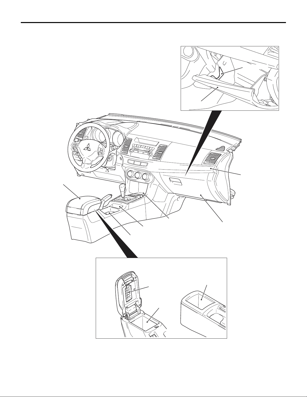
INSTRUMENT PANEL AND FLOOR CONSOLE
Card holder
Glove box
Ornament panel
Armrest
M2520001000793
Tr ay
Cup holder
Type B Type C
The instrument panel and the floor console have the
following features.
• The instrument panel is two-toned.
Center tray
Console box
Tissue paper
holder
Console box
Glove box
• The division unit of each part has been enlarged,
also the gap and level difference between the
instrument panel has been minimized to achieve
the delicate quality.
AC609712
Page 4

52A-4
INTERIOR
INSTRUMENT PANEL AND FLOOR CONSOLE
• The decorated panel creating uniformity from the
instrument panel to the door trim has been
adopted.
• The holder in which two cards can be stored has
been installed in the glove box.
• The glove box with damper function has been
installed. <Except DE>
• The center tray for storing small items has been
installed in front of the selector or shift lever cen
ter panel.
• The cup holder which can hold two 20-oz bottles
has been equipped. The cup holder can store two
CDs in the upright position and pen-size long
items horizontally.
• Under the arm rest of type B, a large box that can
store 6 CDs has been equipped. (9 CDs for type
C)
• A tray that can store cigarettes and lighters has
-
been equipped. <Vehicles without console
switch>
• The synthetic cloth is used for the arm rest lid to
enhance luxury and soft feelings.
Page 5
INTERIOR
SEAT
SEAT
52A-5
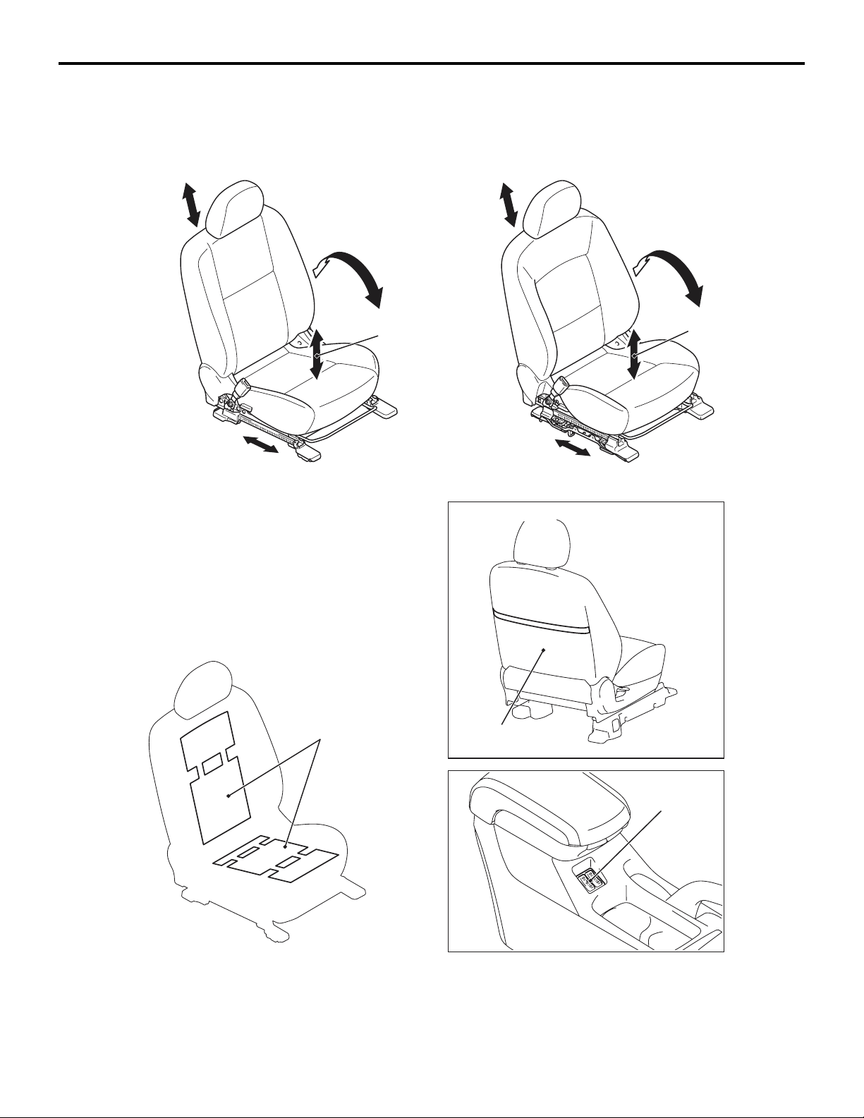
FRONT SEAT
Head restraint
vertical adjustment
Sliding adjustment Sliding adjustment
<Standard type>
M2520004000996
<Sports type>
Head restraint
vertical adjustment
Reclining adjustment Reclining adjustment
Height adjustment
(Driver's side)
<Driver's seat>
Height adjustment
(Driver's side)
<Heated seat>
Seat heater
Seatback pocket
<Except DE>
Heated seat
switch
AC609378
The front seats offer the following advantages. • The cross frame has been installed below the
seat cushion to reduce a risk of injury by restrain
ing the forward travel of the passenger. (Waist
position travel reduction frame structure)
AB
-
Page 6
52A-6
INTERIOR
SEAT
• The seat frame and head restraint have been
installed to the proper positions to minimize the
severity of whiplash injury at rear-end collision at
a low speed. (Whiplash injury reduction seat
structure)
• The overall height mechanism raises and lowers
the seat cushion together with the seatback, thus
the driver's posture is always kept at the best
position, resulting in the improved riding comfort.
• The pump-type height lever has been adopted for
easier operation with a light force by the vertical
adjustment system. Also, the height adjustment
amount has been increased for more optimum
driving position.
• The variable hardness pad has been adopted for
the sporty-look seat with increased bucket
amount of side bolster in order to establish the
sporty shape with support function <GTS>, and
the standard shape which is basic and for actual
use and comfortable driving.
• Heated seats are available for the driver's and
passenger's seats. <ES, GTS: Option>
• The genuine leather for the seat has been
upgraded to enhance the texture and luxury feel
ing. <GTS: Option>
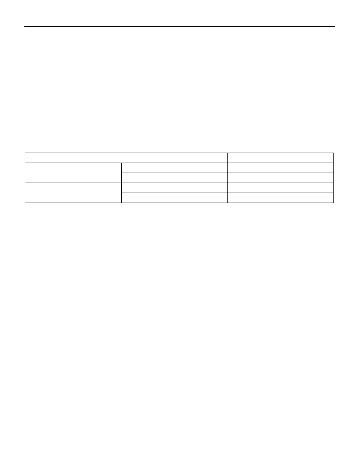
SPECIFICATIONS FOR HEATED SEAT
Item Specifications
ENERGY CONSUMPTION W HIGH 61 ± 6.1
LOW 16 ± 1.6
THERMOSTAT ° C ON → OFF 40 ± 4
OFF → ON 30 ± 5
-
Page 7
INTERIOR
SEAT
52A-7
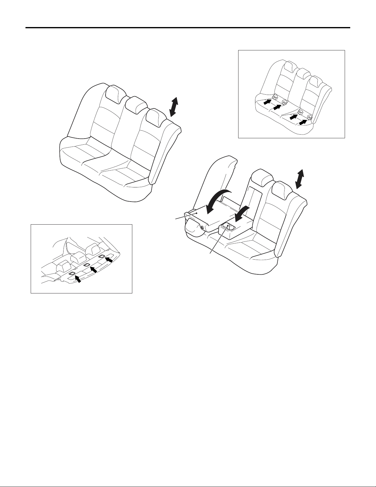
REAR SEAT
<Bench seat>
M2520007000605
<Lower anchorage for child seat>
Head restraint
vertical adjustrment
<Trunk through seat>
Head restraint
vertical adjustrment
Rear seatback
<Uper tether anchor>
forward folding
A low-back bench seat is used for rear seat. The rear
seat offer the following advantages:
• The center armrest has a cup holder.
Cup holder
AC609174
• An upper tether anchor has been installed on the
rear shelf trim, and an ISO-FIX lower anchor has
been installed on the body side.
AB
Page 8
52A-8
INTERIOR
SEAT BELT
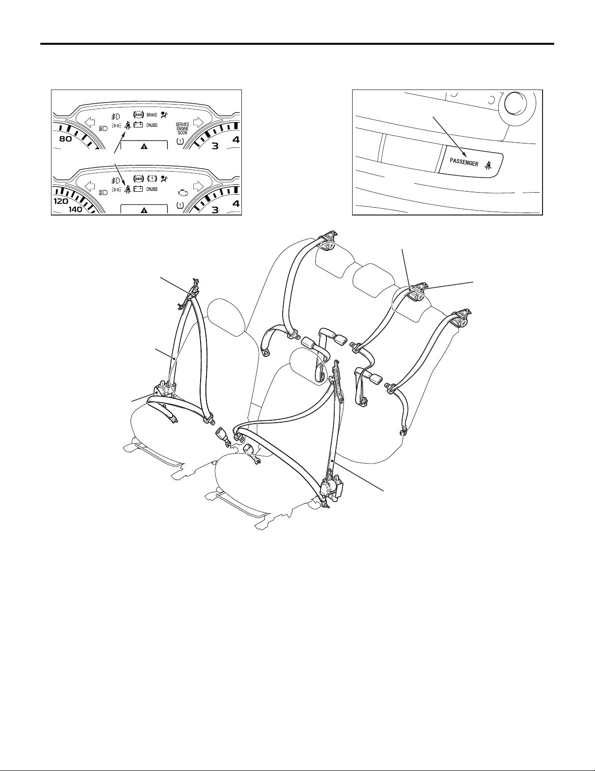
<USA>
<CANADA>
ELR/automatic locking
retractor (ALR) switching
three-point seat belt
Seat belt warning lamp
One-touch push button style
adjustable seat belt
shoulder anchor
SEAT BELT
M2520010000683
Seat belt warning lamp
ELR/automatic locking retractor
(ALR) switching three-point seat belt
Seat belt
retractor
Seat belt retractor
with a pre-tensioner
and force limiter
FRONT SEAT BELT
• An ELR three-point seat belt (driver's side) and
three-point seat belt with ELR/ALR changeover
mechanism (passenger's side) is used.
• One-touch push button style adjustable seat belt
anchor and retractable buckle provide the most
suitable belt fitting.
ELR three-point
seat belt
AC608590
• The seat belt retractor with the force limiter for
the driver’s seat and the front passenger’s seat
increase safety.
• A seat belt warning light is installed to the driver’s
and passenger’s seat.
REAR SEAT BELT
• 3-point seat belt with Automatic Locking Retractor (ALR)/ELR changeover mechanism
(LH/RH/Center) is used for the rear seat.
AB
Page 9
BELT
TORSION BAR
SPINDLE
AC100083
AB
INTERIOR
SEAT BELT
52A-9
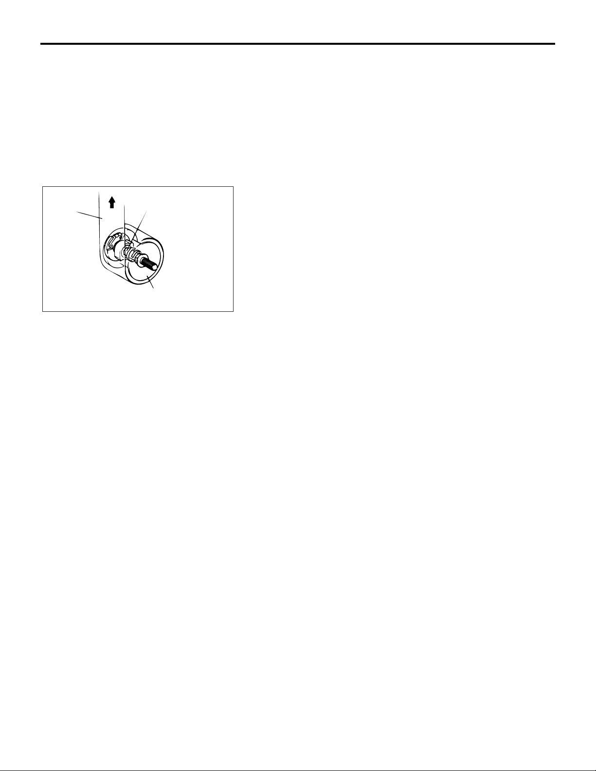
SEAT BELT RETRACTOR WITH FORCE LIMITER
.
The driver’s/front passenger’s seat belt retractor has been
equipped with a force limiter. The force limiter is a device which
operates when a predetermined force is applied, and limits the
force.
.
OPERATION
1. If a collision energy is transmitted to the seat belt, the ELR
mechanism will operate to lock the seat belt.
2. If the energy increases to a predetermined value, the torsion
bar will be distorted. As the spindle rotates together with the
torsion bar, the seat belt webbing is pulled out, reducing the
impact to the occupants.
Page 10
52A-10
INTERIOR
TRIMS
TRIMS
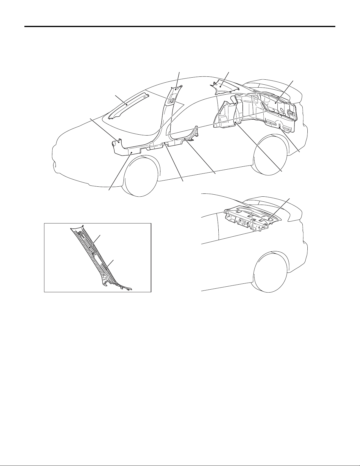
INTERIOR TRIMS
Front pillar trim
Cowl side trim
Front scuff plate
Center pillar trim upper
Center pillar trim lower
Rear pillar trim
Rear scuff plate
M2520012000559
Trunk lid trim
Rear end trim
Trunk side trim
Rear shelf trim
Energy absorption rib
Front pillar trim
(back side)
• The interiors are fully covered by trims.
• The energy absorption rib molding located in the
back side of the front pillar trim and the rear pillar
trim protect head from side impacts and the resin
materials for the trims are unbreakable materials.
AC608126
AB
• Use of nonflammable materials for the trims has
increased safety as outstanding interiors. Also,
material codes are indicated to deal with recy
-
cling easily.
Page 11
INTERIOR
TRIMS
52A-11
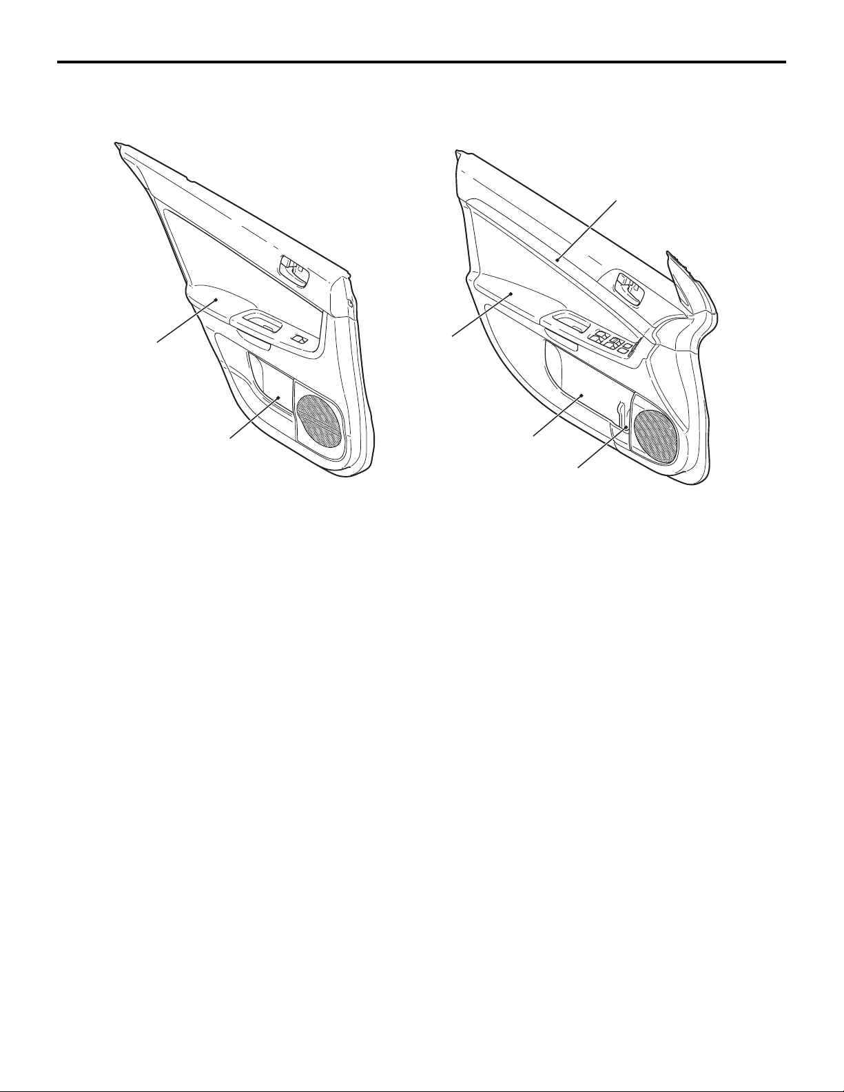
DOOR TRIM
Armrest
Door pocket
M2520012300594
<Front door trim><Rear door trim>
Ornament panel
Armrest
Door pocket
Bottle holder
• The decorated panel has been adopted for the
front door trim.
• The bottle holder for bottles with shapes that are
difficult to keep upright has been adopted for the
front door pocket.
• The front door pocket with a large capacity has
been adopted for items such as A4-size map.
Also, the rear door pocket has been added.
AC608432
AB
• The shock absorbing arm rest has been adopted
which reduces the mid section injuries to passen
gers by collapsing upon side impact.
• The arm rest which is formed with cloth has been
adopted to create a continuous flow with the
ornament section.
-
Page 12
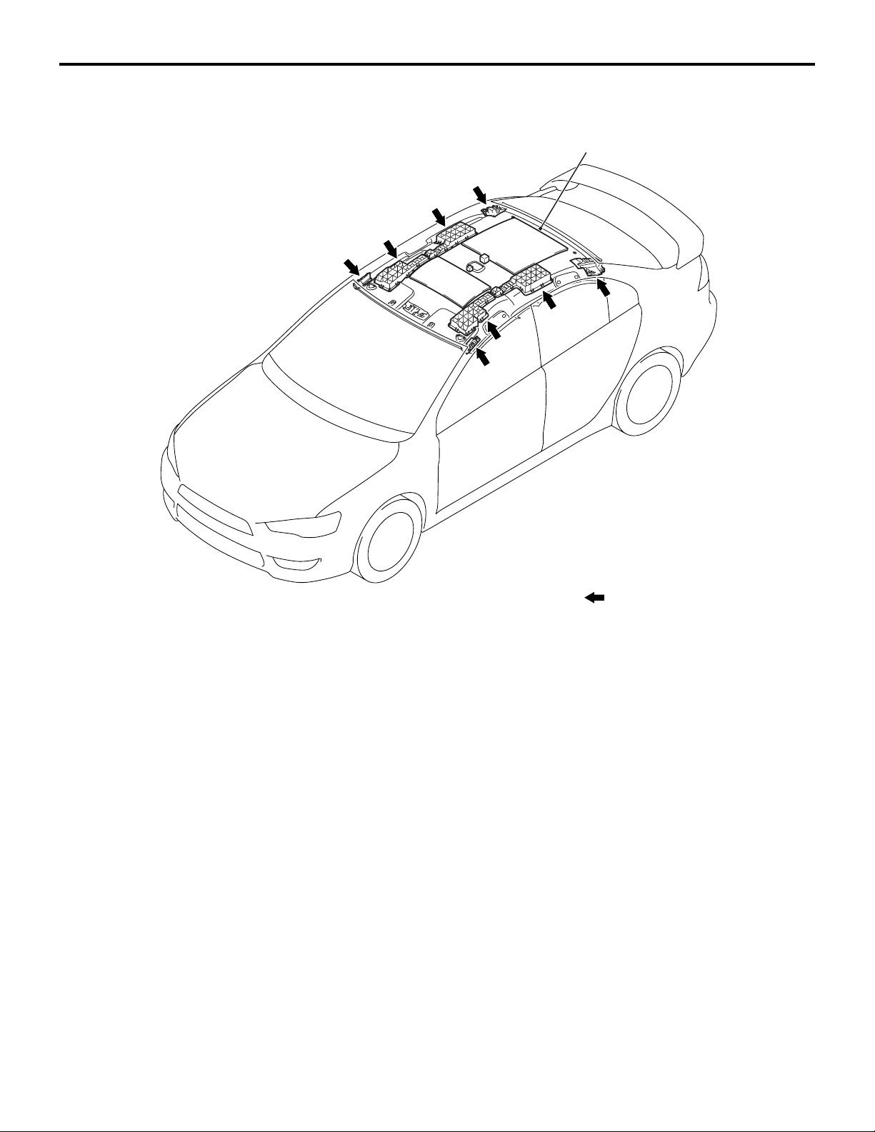
52A-12
INTERIOR
HEADLINING
HEADLINING
M2520014000306
Headliner
Interior design with safe material has been adopted,
achieving more safe and comfortable interior.
NOTE
: Energy absorption box positions
AC608128AC
• Energy absorption pad and rib have been
adopted to the inside of headliner. This reduces
head injuries upon the secondary impact against
the cabin during a collision, and improves safety.
Page 13
GROUP 52A
INTERIOR
CONTENTS
52A-1
GENERAL DESCRIPTION. . . . . . . . . 52A-2
SPECIAL TOOL . . . . . . . . . . . . . . . . . 52A-2
INSTRUMENT PANEL ASSEMBLY*. 52A-2
REMOVAL AND INSTALLATION . . . . . . . . 52A-2
GLOVE BOX . . . . . . . . . . . . . . . . . . . 52A-5
REMOVAL AND INSTALLATION . . . . . . . . 52A-5
INSTRUMENT CENTER PANEL . . . . 52A-6
REMOVAL AND INSTLLATION . . . . . . . . . 52A-6
INSTRUMENT LOWER PANEL. . . . . 52A-7
REMOVAL AND INSTALLATION . . . . . . . . 52A-7
FLOOR CONSOLE ASSEMBLY . . . . 52A-8
REMOVAL AND INSTALLATION . . . . . . . . 52A-8
TRIMS. . . . . . . . . . . . . . . . . . . . . . . . . 52A-10
REMOVAL AND INSTALLATION . . . . . . . . 52A-10
DOOR TRIM . . . . . . . . . . . . . . . . . . . . 52A-13
REMOVAL AND INSTALLATION . . . . . . . . 52A-13
HEADLINING . . . . . . . . . . . . . . . . . . . 52A-15
REMOVAL AND INSTALLATION . . . . . . . . 52A-15
INSIDE REAR VIEW MIRROR . . . . . . 52A-17
FRONT SEAT ASSEMBLY* . . . . . . . . 52A-17
REMOVAL AND INSTALLATION . . . . . . . . 52A-17
INSPECTION. . . . . . . . . . . . . . . . . . . . . . . . 52A-19
DISASSEMBLY AND ASSEMBLY . . . . . . . 52A-21
REAR SEAT ASSEMBLY. . . . . . . . . . 52A-23
REMOVAL AND INSTALLATION . . . . . . . . 52A-23
DISASSEMBLY AND ASSEMBLY . . . . . . . 52A-26
FRONT SEAT BELT* . . . . . . . . . . . . . 52A-28
REMOVAL AND INSTALLATION . . . . . . . . 52A-28
INSPECTION. . . . . . . . . . . . . . . . . . . . . . . . 52A-29
REAR SEAT BELT . . . . . . . . . . . . . . . 52A-31
REMOVAL AND INSTALLATION . . . . . . . . 52A-31
WARNINGS REGARDING SERVICING OF SUPPLEMENTAL RESTRAINT SYSTEM (SRS) EQUIPPED VEHICLES
WARNING
•
Improper service or maintenance of any component of the SRS, or any SRS-related component, can lead to
personal injury or death to service personnel (from inadvertent firing of the air bag) or to the driver and
passenger (from rendering the SRS inoperative).
•
Service or maintenance of any SRS component or SRS-related component must be performed only at an
authorized MITSUBISHI dealer.
•
MITSUBISHI dealer personnel must thoroughly review this manual, and especially its GROUP 52B - Supplemental
Restraint System (SRS) before beginning any service or maintenance of any component of the SRS or any
SRS-related component.
NOTE
The SRS includes the following components: SRS air bag control unit, SRS warning light, front impact sensors, driver’s and
passenger’s (front) air bag modules, knee air bag module, side-airbag module, curtain air bag module, side impact sensors,
seat belt pre-tensioners, clock spring, and interconnecting wiring. Other SRS-related components (that may have to be
removed/installed in connection with SRS service or maintenance) are indicated in the table of contents by an asterisk (*).
Page 14
52A-2
INTERIOR
GENERAL DESCRIPTION
GENERAL DESCRIPTION
OPERATION
.
SEAT BELT WARNING SYSTEM
If the driver turns the ignition switch to the "ON" position without fastening the seat belt, the seat belt
warning light illuminates.
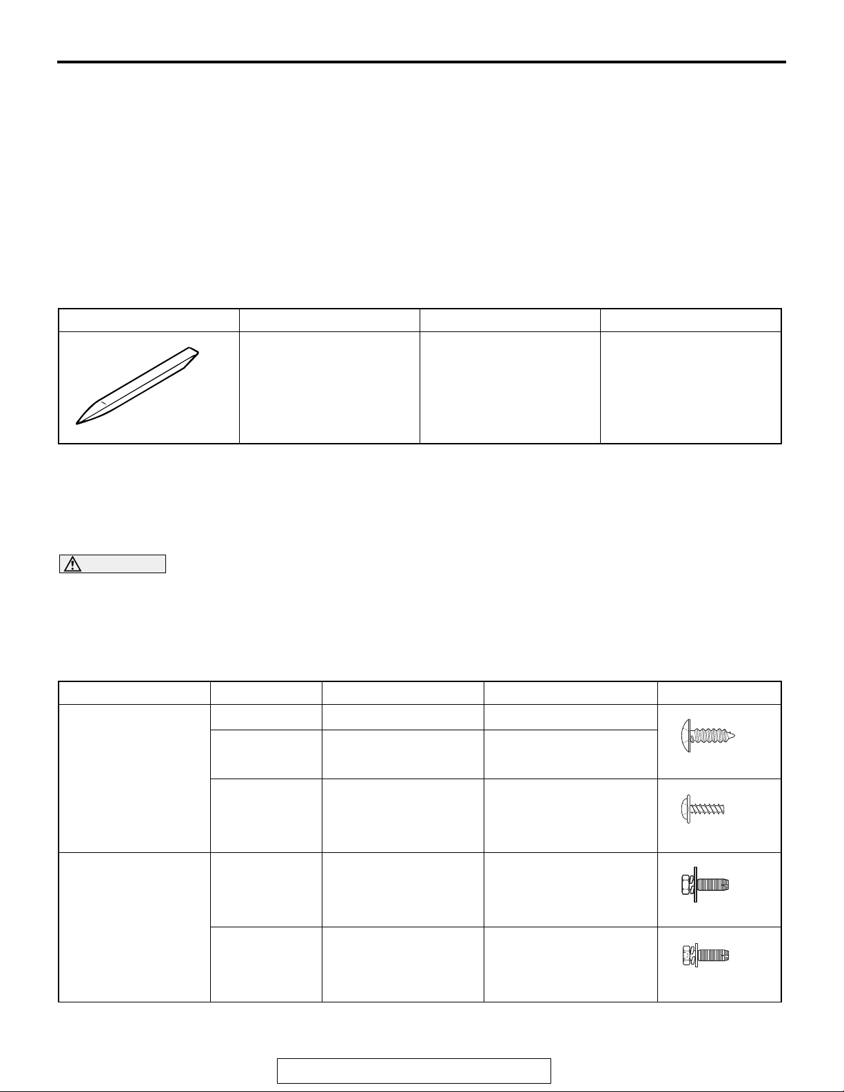
SPECIAL TOOL
Tool Tool number and name Supersession Application
MB990784
Ornament remover
MB990784
General service tool Removal of switch, trim,
etc.
M1521000100429
M1521000600576
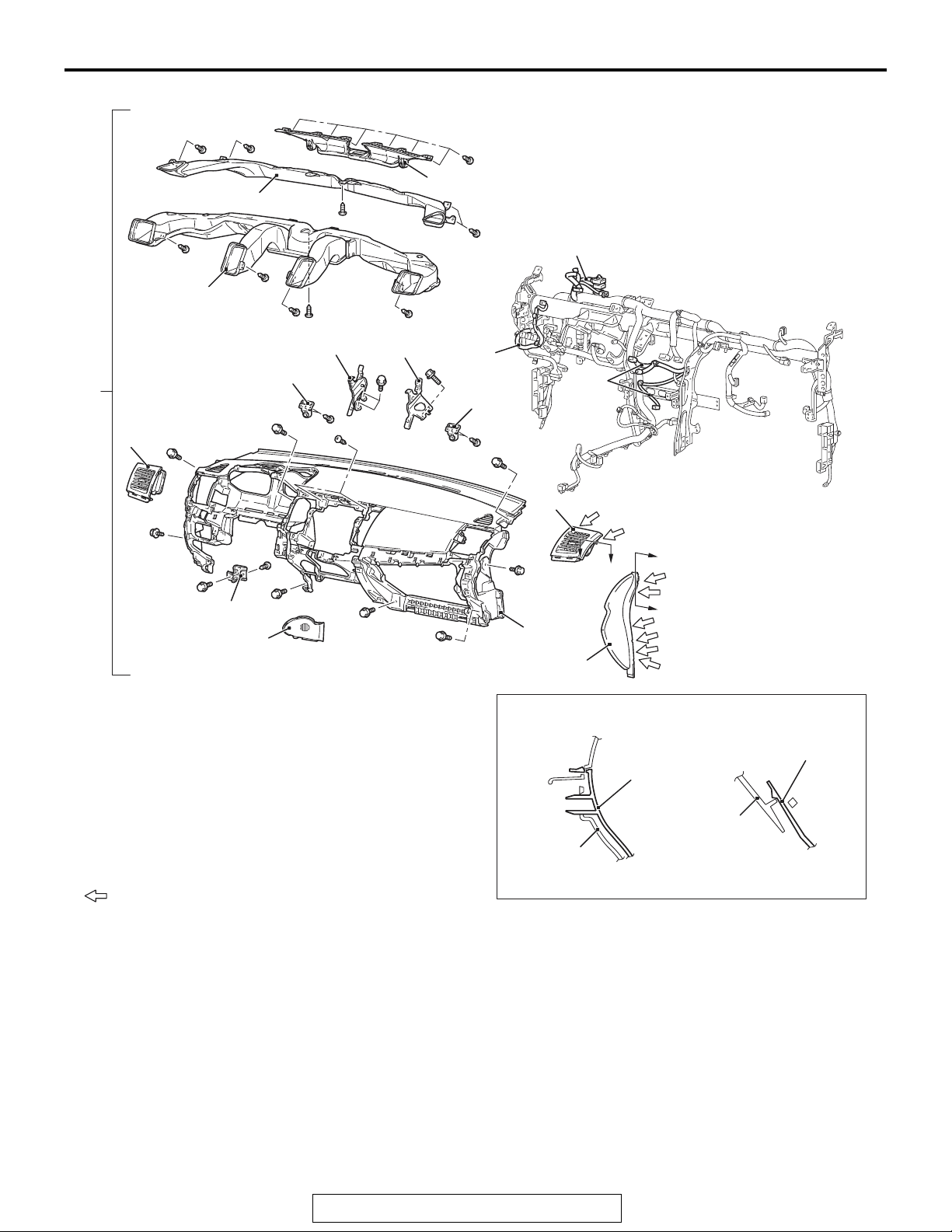
INSTRUMENT PANEL ASSEMBLY
REMOVAL AND INSTALLATION
WARNING
For removal and installation of the passenger's side air bag module, always observe the service procedures described in GROUP 52B, Air Bag Module and Clock Spring P.52B-367.
The following bolts and screws are used for installing the instrument panel. Bolts and screws are indicated as
marks shown in the illustration in the sections of "Removal and Installation" and "Disassembly and Assem
bly."
Name Symbol Size (D × L) mm Color Shape
Tapping screw a 5 × 12
b 5 × 16
c 5 × 12
Bolt with washer d 5 × 20
−
−
−
−
M1521001701591
-
AC104450
AC104436
e 6 × 16
D: Thread diameter, L: Effective thread length
TSB Revision
AC104417
−
AC104429
Page 15
INTERIOR
INSTRUMENT PANEL ASSEMBLY
52A-3
CAUTION
• Refer to GROUP 52B-SRS Service Precautions P.52B-24 and Air bag Module and Clock Spring
P.52B-367 before removing the passenger side air bag module.
• Do not subject the SRS-ECU to any shocks when removing or installing the instrument panel.
Pre-removal and Post-installation Operation
• Removal and Installation of Front Pillar Trim (Refer to
P.52A-10).
• Removal and Installation of Instrument Under Cover
(Refer to
• Removal and Installation of Glove Box (Refer to
P.52A-10).
• Removal and Installation of Instrument Cover Lower, Air
Outlet Garnish (Refer to
• Removal and Installation of Audio Unit (Refer to GROUP
54A, Radio with CD Player
• Removal and Installation of Audio Visual Navigation Unit,
GPS antenna (Refer to GROUP 54A, MMCS
• Removal and Installation of Steering shaft (Refer to
GROUP 37, Steering Column Shaft
• Removal and Installation of Hands-free Cellular Phone
System (Refer to GROUP 54A, Hands-free Module
P.54A-435).
• Removal and Installation of Sensors (Refer to GROUP
55B, Interior Temperature Sensor
P.52A-10).
P.52A-10).
P.54A-307).
P.54A-391).
P.37-25).
P.55B-25).
TSB Revision
Page 16
52A-4
INTERIOR
INSTRUMENT PANEL ASSEMBLY
AC608286
c
c
c
11
10
c
9
c
c
7
5
d
3
d
a
c
4
a
8
c
b
c
8
e
4
e
4
7
c
d
3
d
c
d
6
d
d
2
d
d
12
B
B
A
A
1
Note
: Claw positions
1. Instrument panel side cover
• .
2. Instrument panel console side cover
3. Instrument panel side air outlet
4. Instrument panel harness clamp
5. Instrument panel assembly
•
Removal steps
Combination meter (Refer to GROUP
54A, Combination Meter
P.54A-90).
Photo sensor (Refer to GROUP 55B,
Sensors
P.55B-25).
Section A – A Section B – B
Instrument panel
Instrument panel
side cover
Instrument
panel core
Instrument
panel core
side air outlet
Removal steps (Continued)
Passenger’s (front) air bag module
•
(Refer to GROUP 52B, Air Bag
Module(s) and Clock Spring
P.52B-367).
6. Instrument panel side bracket lower
7. Instrument panel holder
8. Instrument panel reinforcement
center
9. Ventilator air distribution duct
10. Side defroster duct
11. Defroster nozzle
12. Instrument panel
AC610166
AB
TSB Revision
Page 17
INTERIOR
GLOVE BOX
GLOVE BOX
52A-5
REMOVAL AND INSTALLATION
5
4
M1521011500034
Section A – A
2
3
A
A
B
B
Instrument
panel
Clip
Glove box
side panel
Note
: Clip positions
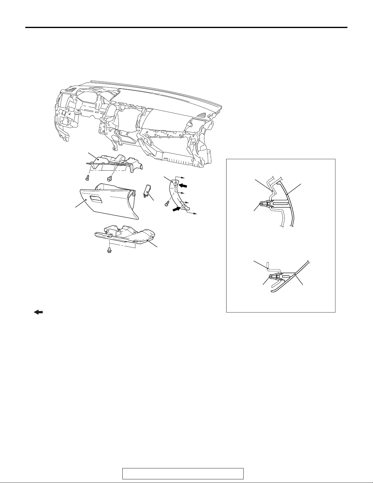
1. Bottom cover (passenger side)
2. Glove box side panel
3. Glove box damper <Vehicles with
Removal steps
glove box damper>
Section B – B
1
Instrument
panel
Clip
Removal steps (Continued)
4. Glove box
5. Glove box cover
Glove box
side panel
AC610054
AB
TSB Revision
Page 18
52A-6
INTERIOR
INSTRUMENT CENTER PANEL
INSTRUMENT CENTER PANEL
REMOVAL AND INSTLLATION
B
B
2
3
B
B
A
A
M1521011300030
1
4
Section B – BSection A – A
Clip
Instrument panel
Instrument panel
under cover ,
Instrument panel
Note
: Clip positions
: Claw positions
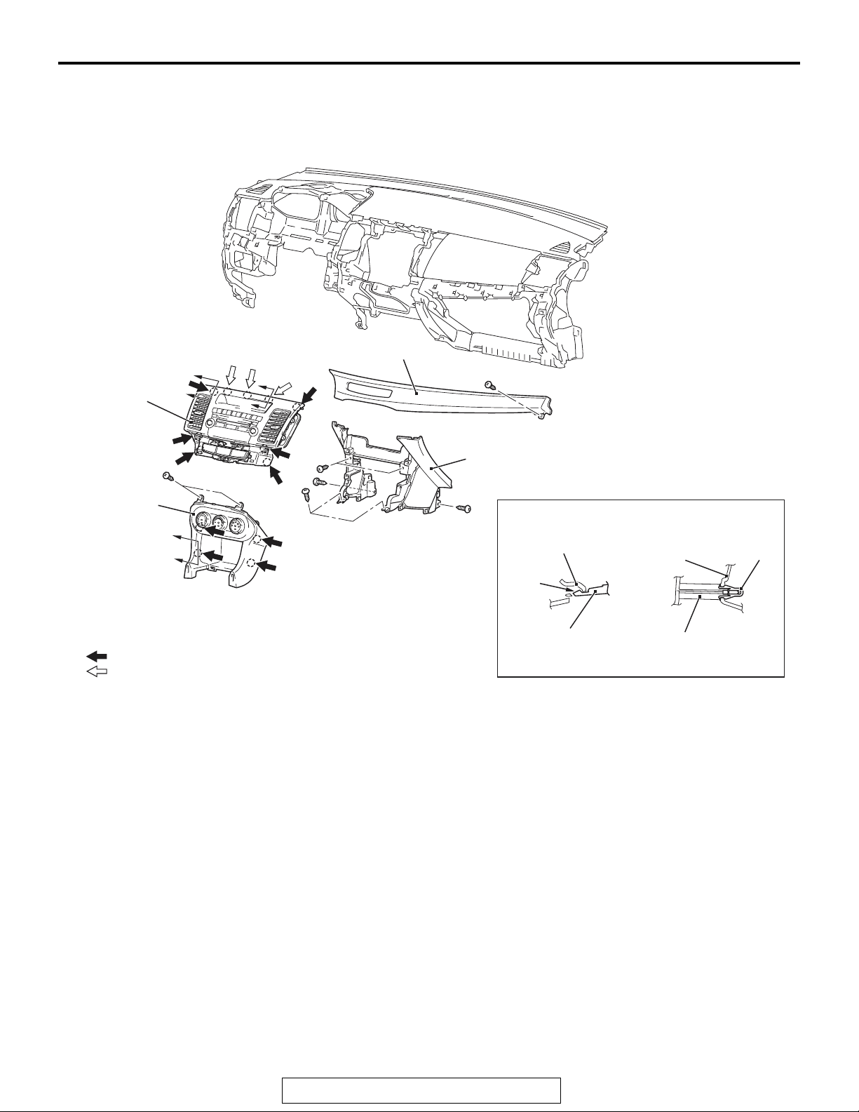
Removal steps
Glove box side panel (Refer
• .
to
1. Instrument panel air outlet garnish
lower (RH)
2. Instrument center panel
P.52A-5).
Claw
Instrument
center panel
Removal steps (Continued)
Floor console assembly (Refer to
• .
P.52A-8).
3. Instrument console box
Floor console side cover (Refer to
• .
P.52A-8).
4. Instrument under cover
Instrument panel
console box ,
Instrument center panel
AC610150
AB
TSB Revision
Page 19
INTERIOR
INSTRUMENT LOWER PANEL
INSTRUMENT LOWER PANEL
52A-7
REMOVAL AND INSTALLATION
2
A
1
Note
: Clip positions
: Claw positions
A
B
M1521011700038
C
C
B
Section A – A
Instrument panel
Clip
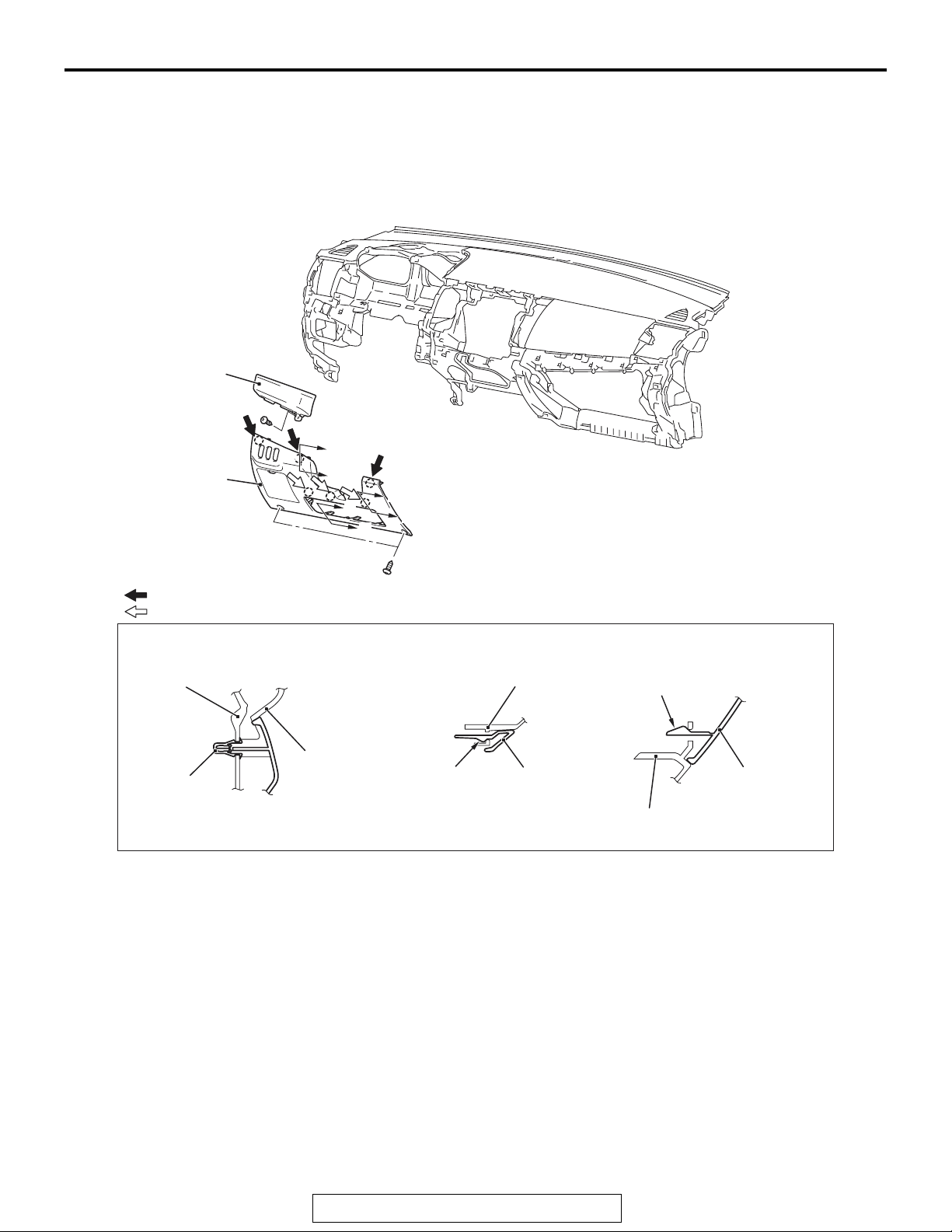
Removal steps
1. Instrument panel cover lower
2. Instrument panel air outlet garnish
lower (LH)
Bottom cover
assembly
Section B – B Section C – C
Claw
Knee airbag
Instrument panel
cover lower
Claw
Instrument panel
cover lower
Knee airbag
AC610152
AB
TSB Revision
Page 20
52A-8
INTERIOR
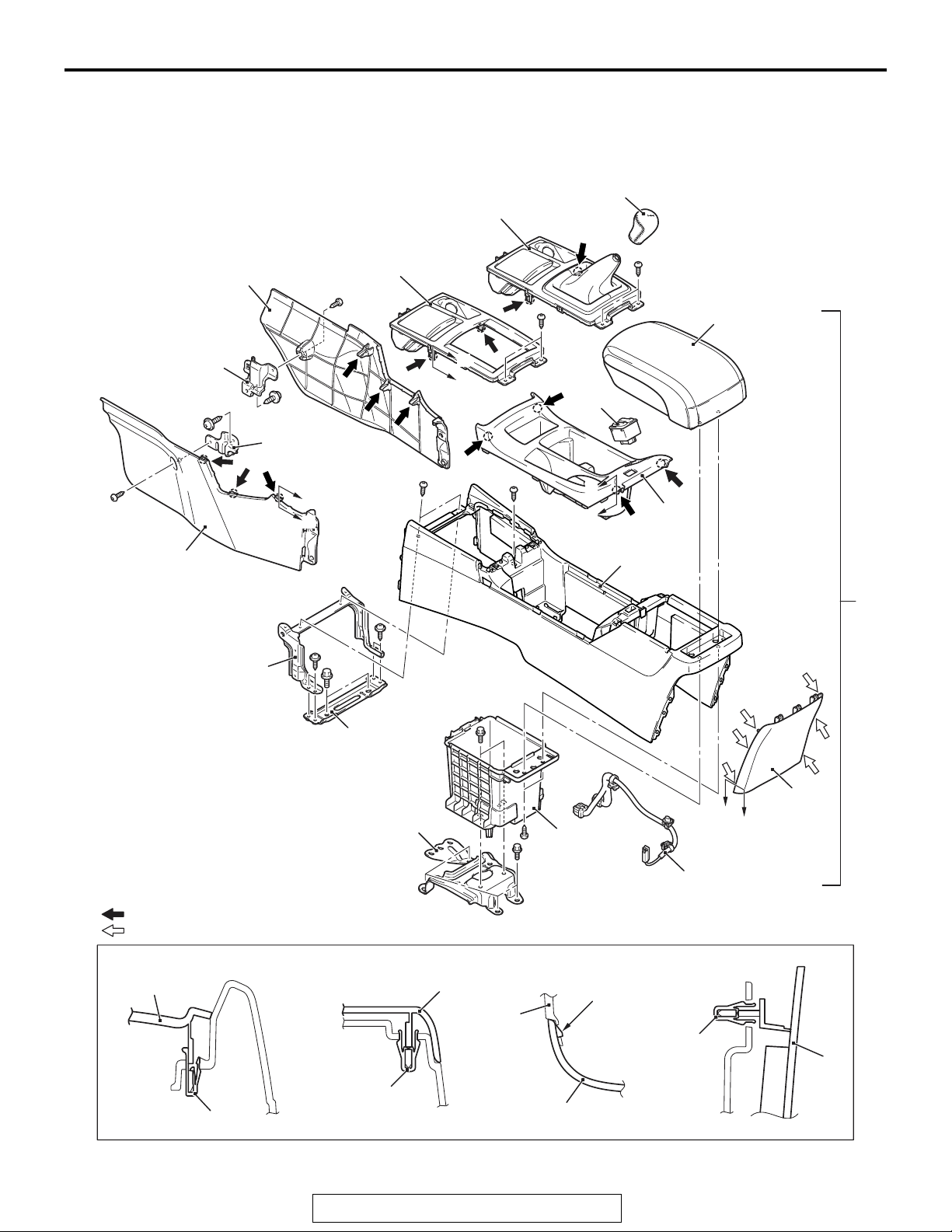
FLOOR CONSOLE ASSEMBLY
FLOOR CONSOLE ASSEMBLY
REMOVAL AND INSTALLATION
14
16
15
D
D
14
4 <A/T>
M1521005200368
3
4
<M/T>
8
A
A
2
B
B
1
10
12
13
11
Note
: Clip positions
: Claw positions
Section A – A Section B – B Section C – C
3
1
10
5
7
C
C
9
6
Section D – D
Claw
Clip
14
Clip
Clip
TSB Revision
7
AC608810
AB
Page 21
INTERIOR
FLOOR CONSOLE ASSEMBLY
52A-9
Removal steps
1. Floor console assembly
2. Heated seat switch
3. Shift knob
4. Floor console panel assembly
5. Floor console assembly
6. Floor console harness
7. Floor console cover
8. Floor console box
Floor console
Floor console
cover
Removal steps (Continued)
9. Floor console lid
>>A<<
10. Floor console
11. Floor console bracket rear
12. Floor console bracket (A)
13. Floor console bracket (B)
14. Floor console side cover
15. Floor console front bracket (LH)
16. Floor console front bracket (RH)
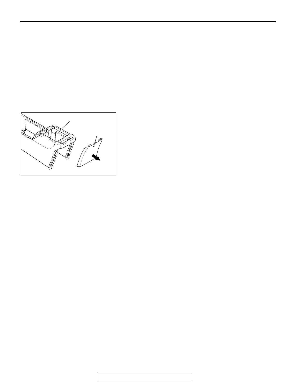
REASSEMBLY SERVICE POINT
.
>>A<< FLOOR CONSOLE REASSEMBLY
Floor console rear ends (shown in the dotted lines) may damage when removing the floor console cover. You can neglect
this damage and floor console is reusable.
AC611409
AB
TSB Revision
Page 22
52A-10
INTERIOR
TRIMS
TRIMS
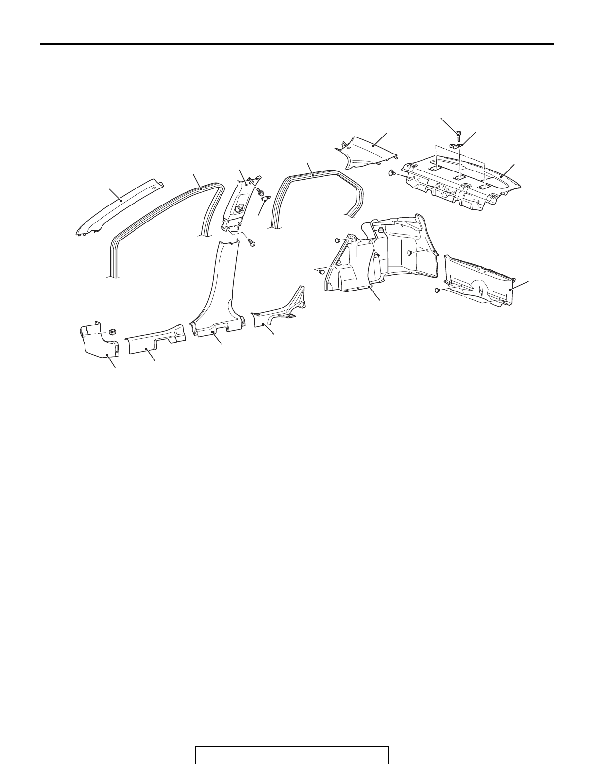
REMOVAL AND INSTALLATION
4
6
1
Removal steps
Rear seat cushion (Refer
P.52A-23).
to
<<A>>
2
1. Front scuff plate
2. Cowl side trim
•
3. Rear scuff plate
4. Front door opening trim
5. Rear door opening trim
6. Front pillar trim
7. Lower center pillar trim
8. Upper center pillar trim cap
M1521001101049
22 ± 4 N·m
16 ± 3 ft-lb
10
9
5
14
11
8
12
13
3
7
Removal steps (Continued)
Outer seat belt (Refer toP.52A-28).
•
9. Upper center pillar trim
10. Rear pillar trim
Seat side back (Refer toP.52A-23).
•
11. Rear shelf trim
12. Rear end trim
13. Trunk side trim
14. Child restraint fitting
Required Special Tool:
• MB990784: Ornament Remover
AC610310
AB
TSB Revision
Page 23
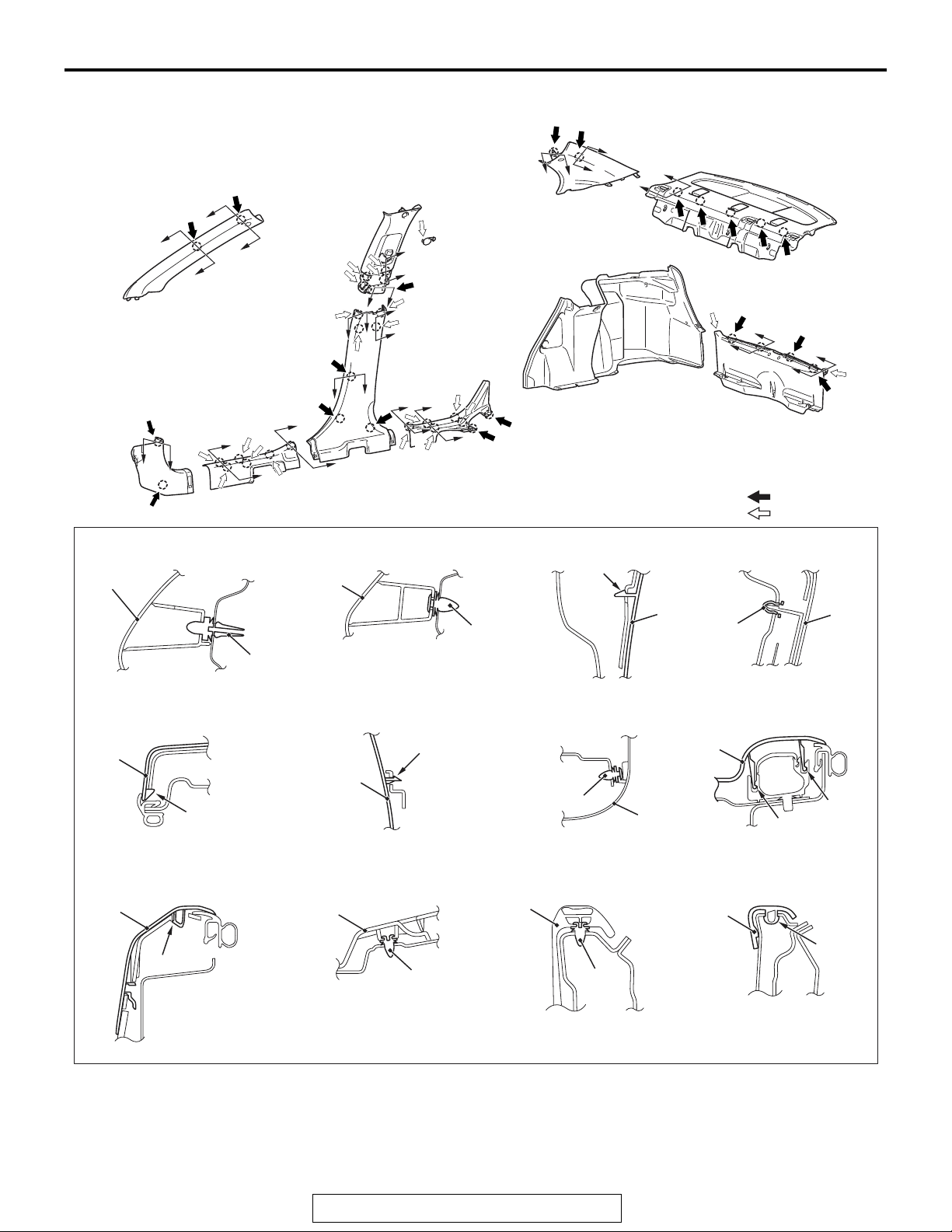
CLIP POSITION
A
B
B
GG
INTERIOR
TRIMS
B
A
A
DD
F
B
B
H
I
I
H
C
C
E
E
F
I
H
I
H
B
A
J
J
K
K
Note
: Clip positions
: Claw positions
52A-11
L
L
Section A – A Section B – B Section C – C Section D – D
Clip
Claw
Clip
9
2
Clip
1, 3
12
Clip
6, 7, 10
11
Clip
Claw
7
12
Clip
6, 10
Section E – E Section F – F Section G – G Section H – H
7
Claw
Section I – I Section J – J Section K – K Section L – L
1, 3
Claw
9
Claw
Claw
Claw
NOTE: Each number in the illustration indicates a
part number.
TSB Revision
AC610026AB
Page 24
52A-12
Section A – A
MB990784
INTERIOR
TRIMS
REMOVAL SERVICE POINT
.
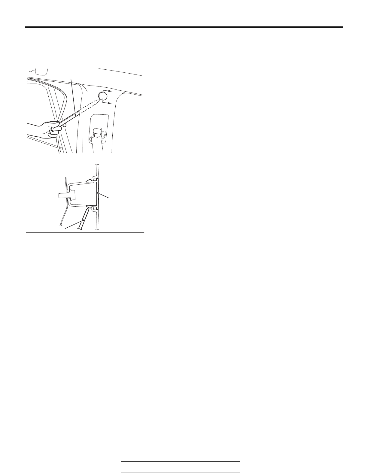
<<A>> UPPER CENTER PILLAR TRIM CAP
REMOVAL
Remove the opening trim. Remove the upper center pillar trim
cap by inserting the special tool MB990784 between the upper
center pillar trim and body as shown in the illustration.
A
A
MB990784
Upper center
pillar trim cap
AC606516
AI
TSB Revision
Page 25
INTERIOR
DOOR TRIM
DOOR TRIM
52A-13
REMOVAL AND INSTALLATION
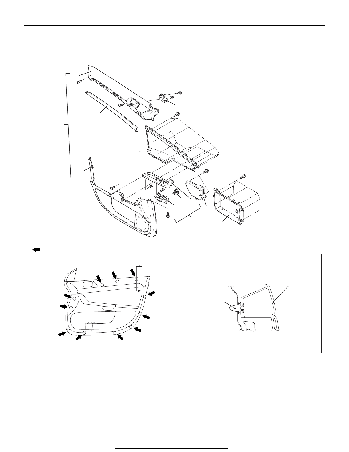
<Front door trim>
5
7
1
12
M1521006400752
6
2
9
11
10
4
Note
:
Clip positions
1. Front door trim assembly
2. Front door ornament
3. Front door pocket
4. Front lower pad energy absorption
5. Front door trim upper
6. Door inside handle
7. Decoration panel
8. Front door power window switch
9. Remote control mirror switch
Removal steps
panel assembly
8
A
A
3
Section A – A
Front door trim
assembly
Clip
AC611164
Removal steps (Continued)
10. Front door power window switch
11. Front power window switch panel
12. Front door trim lower
AB
Required Special Tool:
• MB990784: Ornament Remover
TSB Revision
Page 26
52A-14
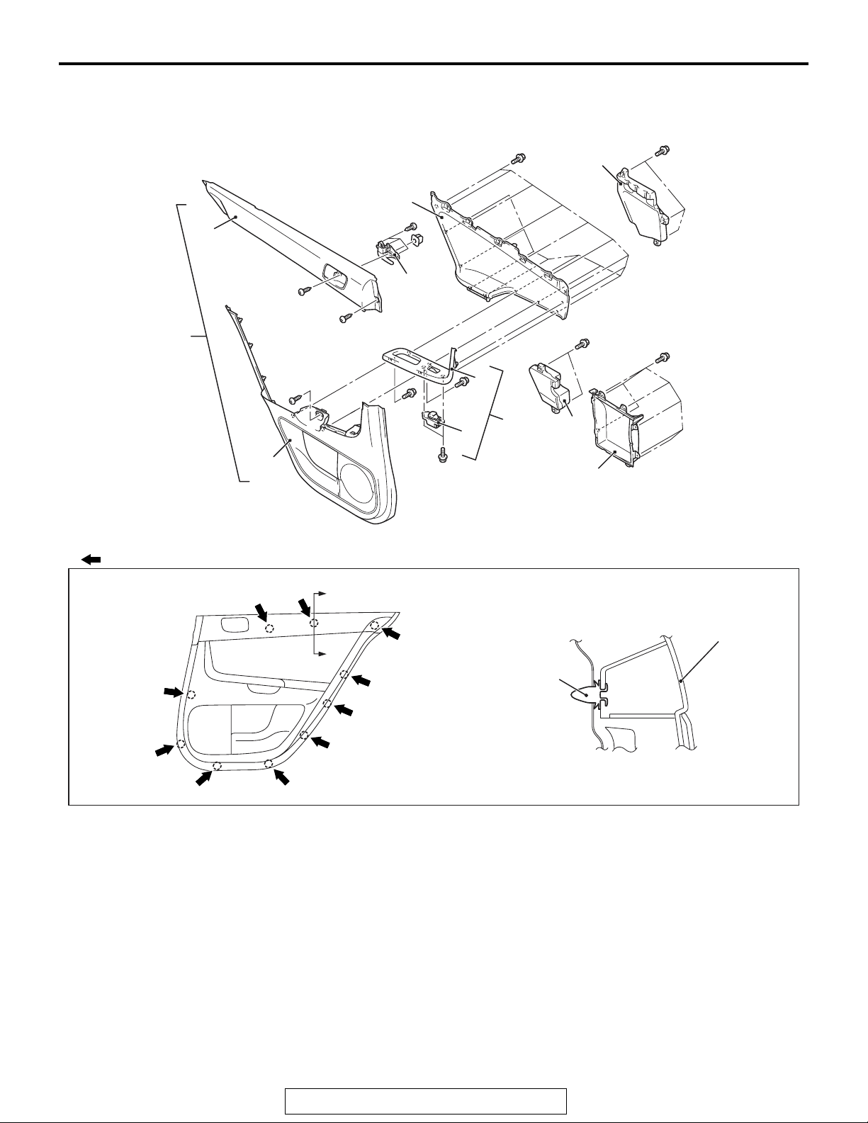
<Rear door trim>
INTERIOR
DOOR TRIM
2
3
6
7
1
10
NOTE
: Clip positions
11
A
A
Removal steps
1. Rear door trim assembly
2. Rear upper pad energy absorption
3. Rear door ornament
4. Rear door pocket
5. Rear lower pad energy absorption
6. Rear door trim upper
7. Door inside handle
8
9
5
4
Section A – A
Clip
Removal steps (Continued)
8. Rear door power window switch
panel assembly
9. Rear door power window switch
10. Rear power window switch panel
11. Rear door trim lower
Required Special Tool:
• MB990784: Ornament Remover
Rear door trim
assembly
AC611175
AB
TSB Revision
Page 27
INTERIOR
HEADLINING
HEADLINING
52A-15
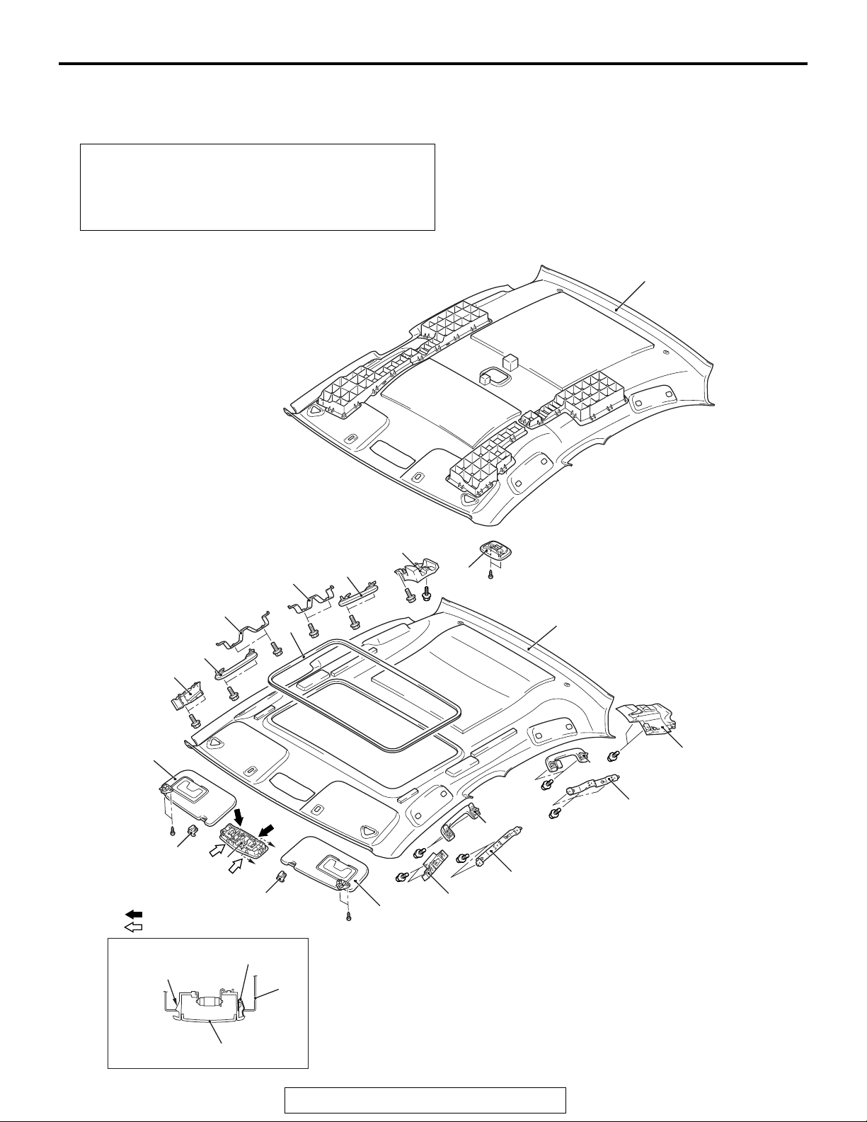
REMOVAL AND INSTALLATION
Pre-removal and Post-installation Operation
• Removal and Installation of Front Pillar Trim, Upper Center Pillar Trim, Rear Pillar Trim (Refer to P.52A-10).
• Removal and Installation of Instrument Under Cover
(Refer to
P.52A-6).
<Vehicles without sunroof>
M1521001400973
7
<Vehicles with sunroof>
8
1
9
4
5
Note
(1) : Clip positions
(2) : Claw positions
Section A – A
Claw
3
Clip
10
8
1
6
2
7
10
1
8
1
A
A
8
5
4
9
8
3
AC609656
AB
TSB Revision
Page 28
52A-16
INTERIOR
HEADLINING
<<A>>
<<B>>
MB990784
Removal steps
1. Assist grip
2. Rear dome light assembly <Vehicles
without sunroof>
3. Front dome light
4. Sun visor assembly
5. Sun visor holder
6. Sunroof lid inner weather strip rear
<Vehicles with sunroof>
7. Headlining
Sun visor holder
Removal steps (Continued)
8. Assist grip bracket
9. Front side roof energy absorption box
<Vehicle with sunroof>
10. Rear side roof energy absorption box
<Vehicle with sunroof>
Required Special Tool:
• MB990784: Ornament Remover
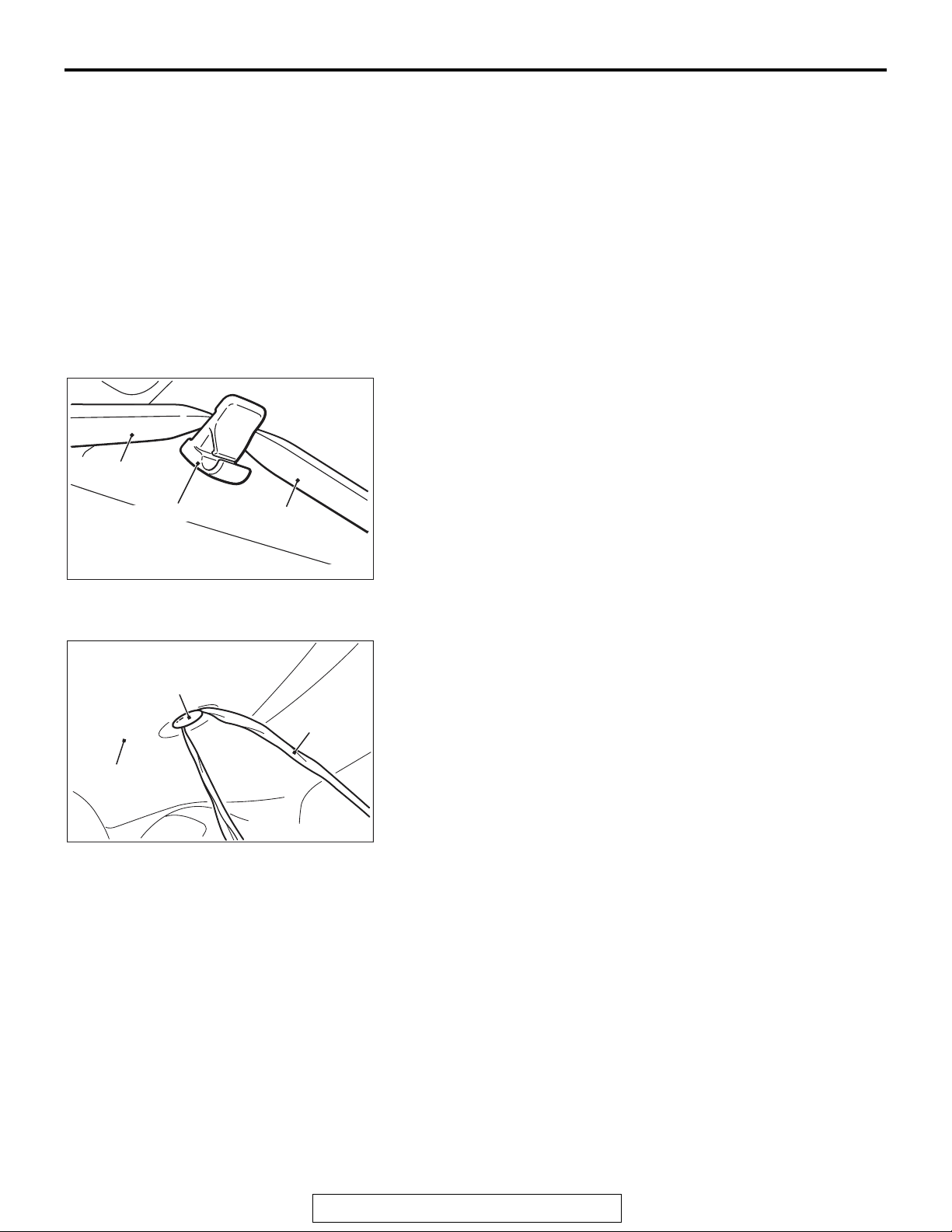
REMOVAL SERVICE POINTS
.
<<A>> SUN VISOR HOLDER REMOVAL
Insert the special tool MB990784 into side claws of the sun
visor holder through the both sides of the sun visor holder to
remove the hinges.
MB990784
Headlining
Clip
AC005512
Vinyl cord
AC600751AD
AF
.
<<B>> HEADLINING ASSEMBLY REMOVAL
To remove the clip, insert a vinyl cord into a clearance between
the clip and the headlining, and pass it around the clip. Then,
pull out the clip downwards while pulling the vinyl cord.
TSB Revision
Page 29
INTERIOR
INSIDE REAR VIEW MIRROR
52A-17
INSIDE REAR VIEW MIRROR
M1521002600561
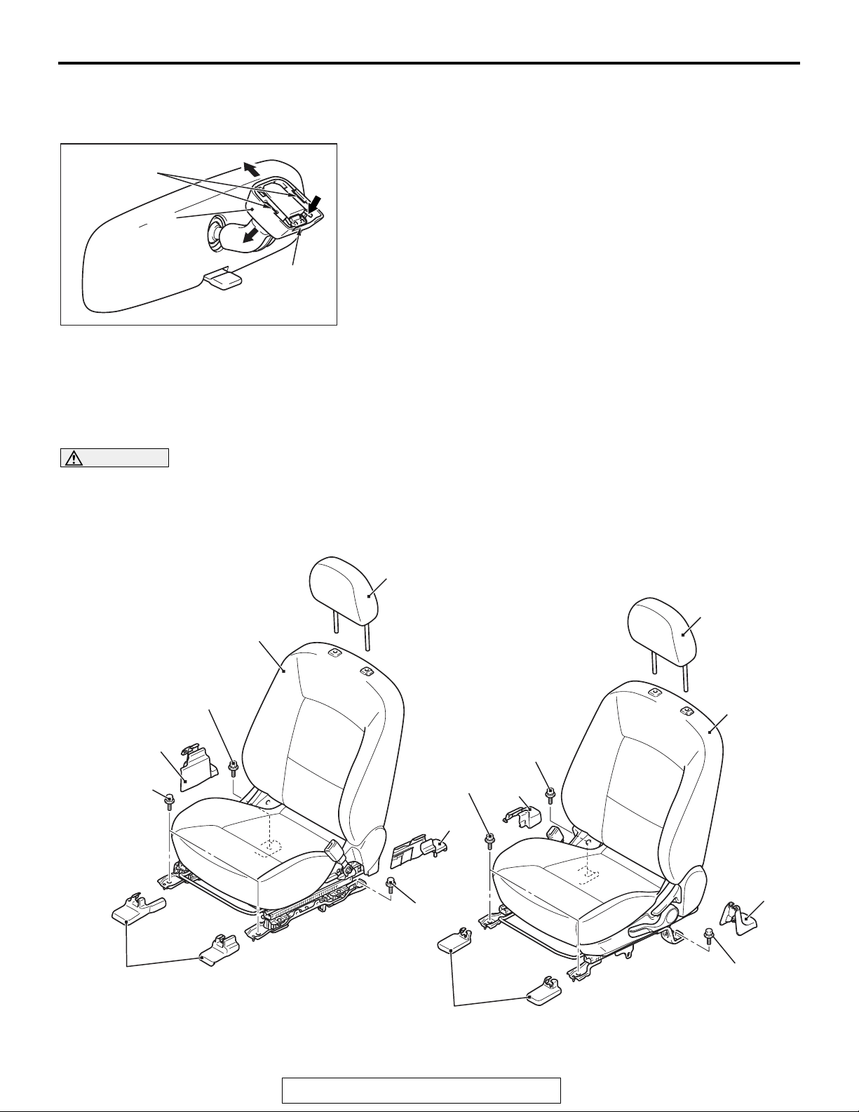
REMOVAL SERVICE POINT
1. Disengage claw A and lower the cover in the arrow 1
direction.
2. Push claw B in the arrow 2 direction to unlock, and pull out
the mirror in the arrow 3 direction.
Claw A
Cover
3
2
1
Claw B
AC209066
AD
FRONT SEAT ASSEMBLY
REMOVAL AND INSTALLATION
WARNING
Before removing the front seat assembly, refer to GROUP 52B, Service Precautions P.52B-24
and Air Bag Module and Clock Spring P.52B-367.
M1522001301165
43 ± 8 N·m
32 ± 6 ft-lb
3
43 ± 8 N·m
32 ± 6 ft-lb
2
1
1
4
4
43 ± 8 N·m
32 ± 6 ft-lb
43 ± 8 N·m
32 ± 6 ft-lb
2
2
2
43 ± 8 N·m
32 ± 6 ft-lb
43 ± 8 N·m
32 ± 6 ft-lb
TSB Revision
3
AC609288
AB
Page 30
52A-18
INTERIOR
FRONT SEAT ASSEMBLY
D-35
D-34
D-33
1. Head restraint
Front seat assembly removal
steps
2. Front seat anchor cover rear
3. Front seat anchor cover front
D-30
D-29
D-32
D-28
D-27
AC611243
AB
Front seat assembly removal steps
(Continued)
<<A>>
>>A<<
Harness connector
•
4. Front seat assembly
REMOVAL SERVICE POINT
.
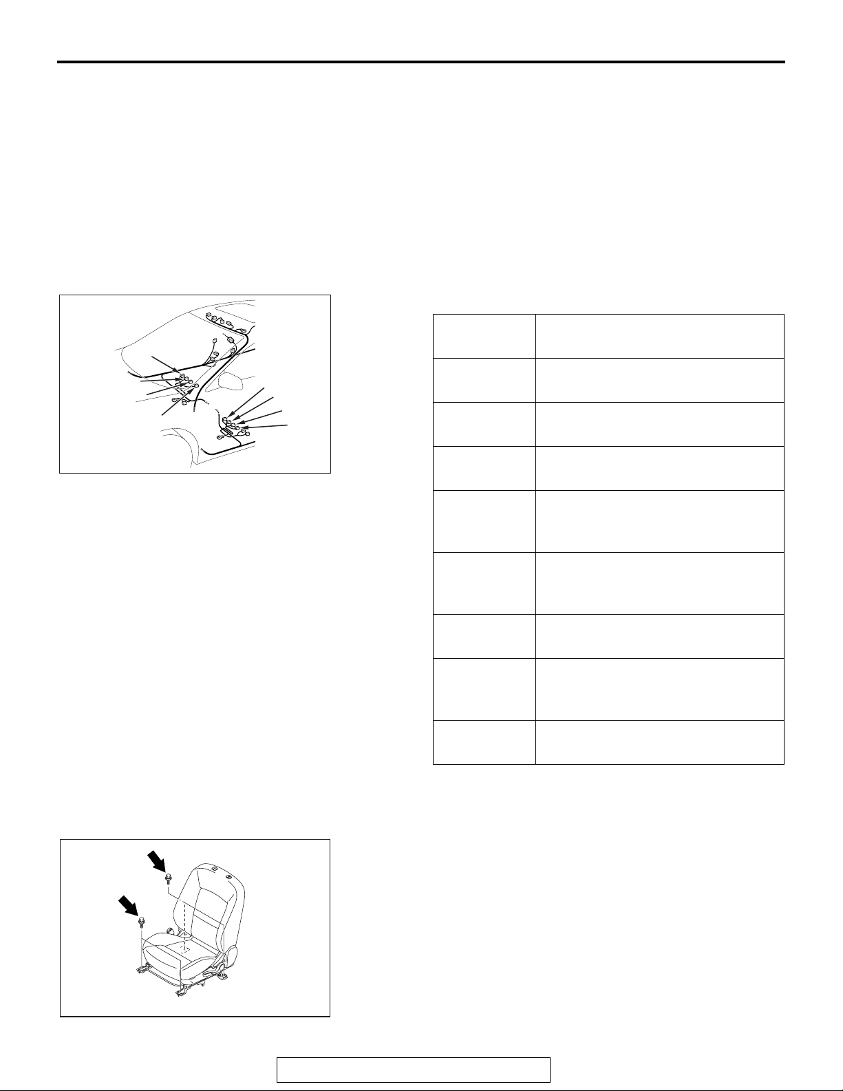
<<A>> WIRING HARNESS CONNECTOR DISCONNECTION
Disconnect the following wiring harness connectors:
Connector
number
D-27 (4 −
black)
D-28 (2 −
gray)
D-29 (4 −
black)
Connector name
Heated seat connector (driver's
seat) <Vehicle with heated seat>
Seat slide sensor connector
(driver's seat)
Seat belt switch connector (driver's
seat)
D-30 (2 −
yellow)
Side air bag module (squib)
connector (driver's seat) <Vehicles
with side air bag>
D-32 (2 −
yellow)
Side air bag module (squib)
connector (front passenger's seat)
<Vehicles with side air bag>
D-33 (4 −
black)
D-34 (4 −
black)
Seat belt switch connector (front
passenger's seat)
Heated seat connector
(passenger's seat) <Vehicle with
heated seat>
D-35 (6) Occupant classification system
connector (passenger's seat)
INSTALLATION SERVICE POINT
.
>>A<< FRONT SEAT ASSEMBLY INSTALLATION
1. Temporarily tighten the bolts in all mounting locations
shown in the illustration with no load applied to the front
seat cushion and check the operation of the seat slide.
2. Tighten the bolts in all mounting locations to the specified
torque.
AC610011
AB
TSB Revision
Page 31
INTERIOR
FRONT SEAT ASSEMBLY
52A-19
ACX00625
INSPECTION
M1522005500287
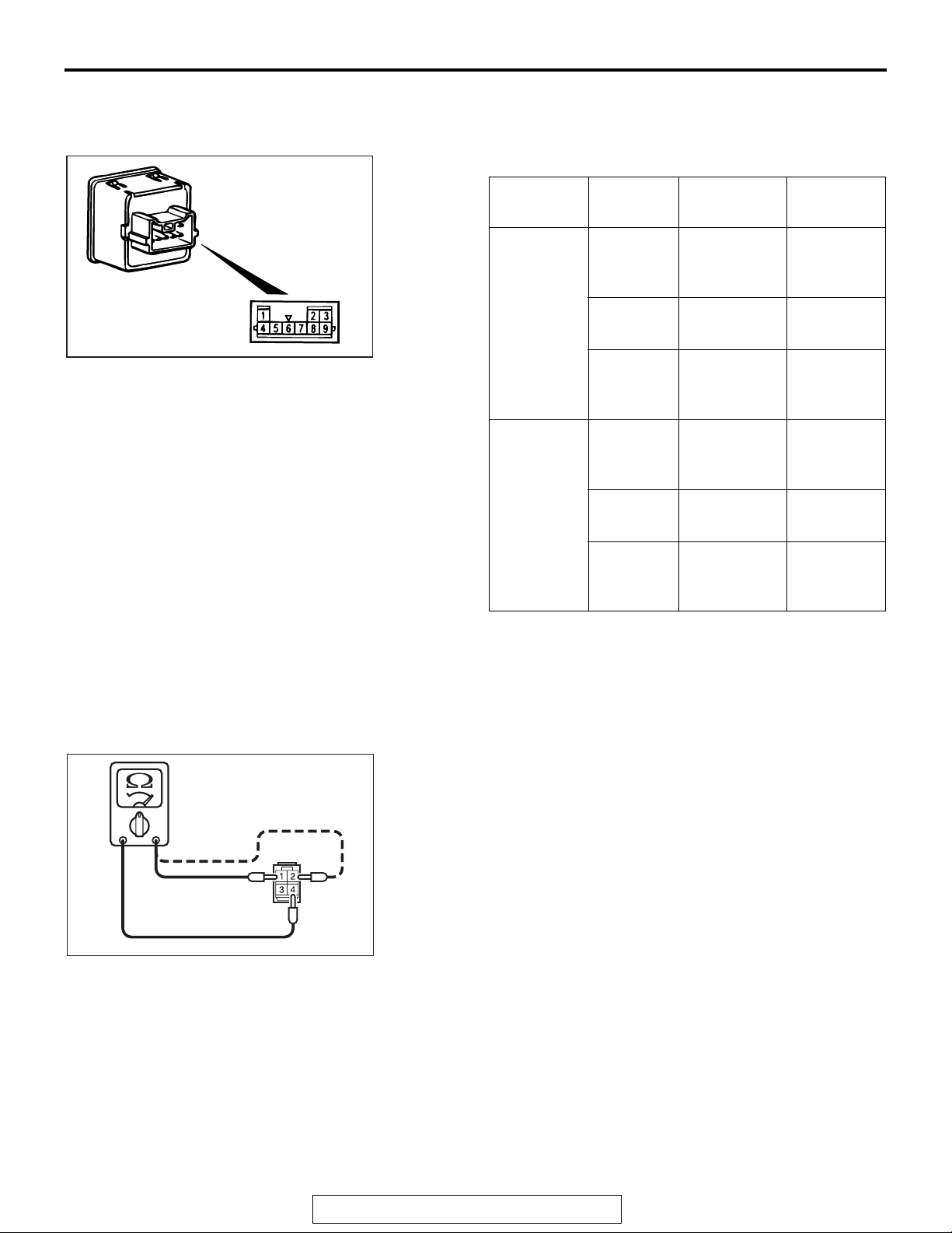
CONTINUITY TEST OF HEATED SEAT SWITCH
.
1. Check for continuity between terminals.
Item Switch
position
Driver's
HI 1 − 5, 3 − 8 Continuity
seat side
OFF 1 − 5, 3 − 5, 5
LO 3 − 5 Continuity
Front
HI 4 − 5, 8 − 9 Continuity
passenger'
s seat side
OFF 4 − 5, 5 − 8, 5
Tester
connection
− 8
− 9
Specified
condition
exists (2
or less)
Open
circuit
exists (2
or less)
exists (2
or less)
Open
circuit
Ω
Ω
Ω
AC610374
LO 5 − 9 Continuity
exists (2
Ω
or less)
2. Check that the indicator is lighted at HI or LO when battery
voltage is supplied to terminal 5 and terminal 8 is grounded.
3. Check that indicator is lighted when battery voltage is
supplied to terminals 2 and terminal 6.
.
SEAT CUSHION HEATER CHECK
Measure the resistance between terminals.
Standard value: At room temperature 20 ° C (68 ° F)
Between terminals 1 and terminal 2
Standard type: Approximately 3.82 ± 4.66 ohms
Spots type: Approximately 4.47 ± 5.48 ohms
Between terminals 1 and terminal 4
Standard type: 8.90 ± 10.88 ohms
Spots type: 8.79 ± 10.75 ohms
.
TSB Revision
Page 32
52A-20
1
2
AC200100
INTERIOR
FRONT SEAT ASSEMBLY
SEATBACK HEATER CHECK
Measure the resistance between terminals.
Standard value: At room temperature 20 ° C (68 ° F)
Standard type: 4.86 ± 5.94 ohms
Spots type: 4.06 ± 4.96 ohms
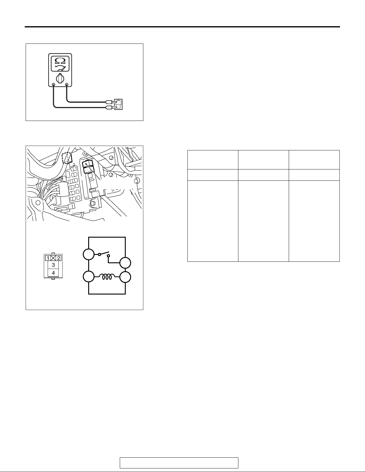
HEATED SEAT RELAY CONTINUITY CHECK
4
1
Heated seat
relay
3
2
AC610364
AB
Battery voltage Tester
connection
Specified
condition
Not applied 3 − 4 Open circuit
• Connect
terminal 1 to
the positive
3 − 4 Continuity
exists (2
Ω or
less)
battery
terminal
• Connect
terminal 2 to
the negative
battery
terminal
TSB Revision
Page 33
INTERIOR
FRONT SEAT ASSEMBLY
52A-21
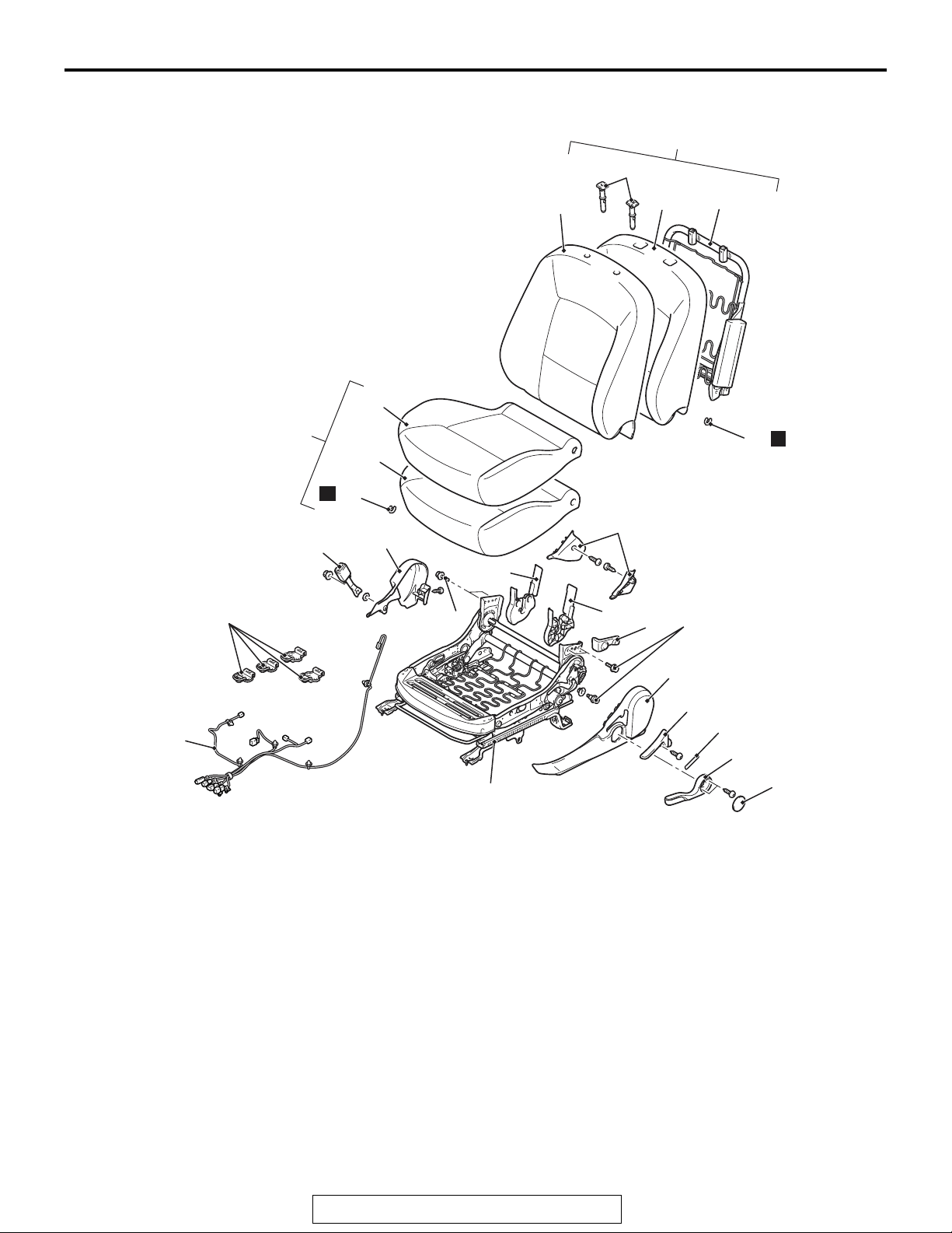
DISASSEMBLY AND ASSEMBLY
21
19
22
N
20
6
M1522001501211
13
AC506551
14
16
17
18
15
N
8
7
10
<<A>>
<<B>>
12
11
Disassembly steps
1. Height adjuster lever cap
2. Height adjuster lever
3. Reclining adjuster cap
4. Reclining adjuster lever
5. Side shield cover
6. Inner seat belt
7. Hinge cover
8. Side shield inner cover
9. Reclining adjuster upper cover
10. Reclining adjuster cover
11. Harness
12. Hook
13. Front seatback pad and frame
assembly
14. Head restraint guide
41 ± 10 N·m
30 ± 8 ft-lb
10
41 ± 10 N·m
30 ± 8 ft-lb
9
5
4
23
Disassembly steps (Continued)
15. Hog ling
16. Front seatback cover
17. Front seatback pad
18. Front seatback frame
19. Front seat cushion assembly
20. Hog ling
21. Front seat cushion cover
22. Front seat cushion pad
23. Front seat cushion frame
Required Special Tool:
• MB990784: Ornament Remover
3
2
1
AC609289AB
TSB Revision
Page 34
52A-22
Height adjuster
lever cover
MB990784
INTERIOR
FRONT SEAT ASSEMBLY
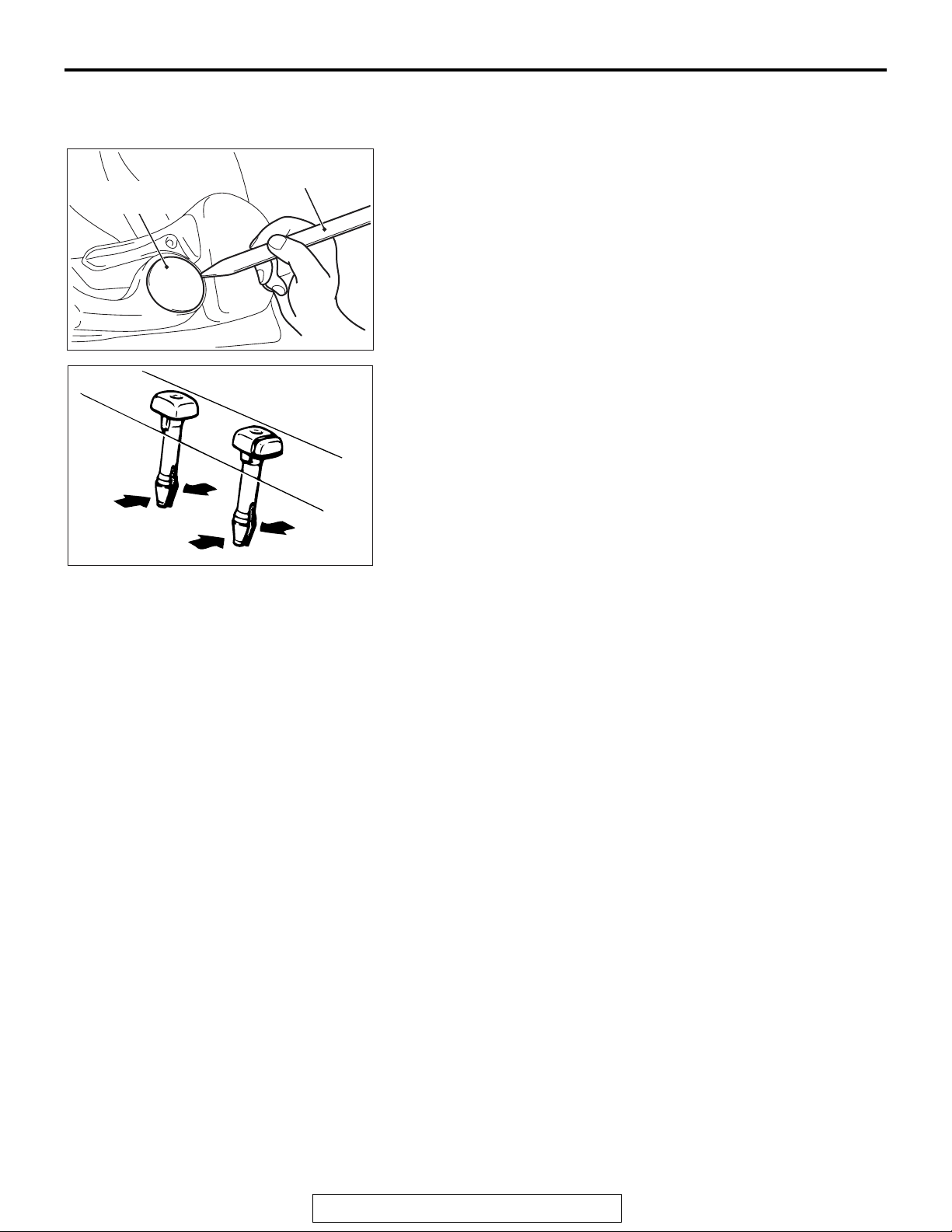
REMOVAL SERVICE POINT
.
<<A>> HEIGHT ADJUSTER CAP REMOVAL
Use special tool MB990784 as shown to remove the height
adjuster lever cover.
.
AC609290
ACX01300
AB
<<B>> HEAD RESTRAINT GUIDE REMOVAL
AB
TSB Revision
Page 35
INTERIOR
REAR SEAT ASSEMBLY
REAR SEAT ASSEMBLY
52A-23
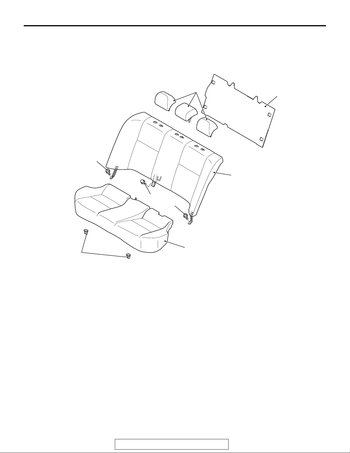
REMOVAL AND INSTALLATION
<Bench seat>
43 ± 8 N·m
32 ± 6 ft-lb
M1522001800639
1
5
3
43 ± 8 N·m
32 ± 6 ft-lb
>>C<<
>>A<<
4
Removal steps
1. Rear seat head restraint
2. Rear seat cushion assembly
3. Rear seatback assembly
2
AC611154
Removal steps (Continued)
4. Rear seat hook
5. Luggage room partition board
AB
TSB Revision
Page 36
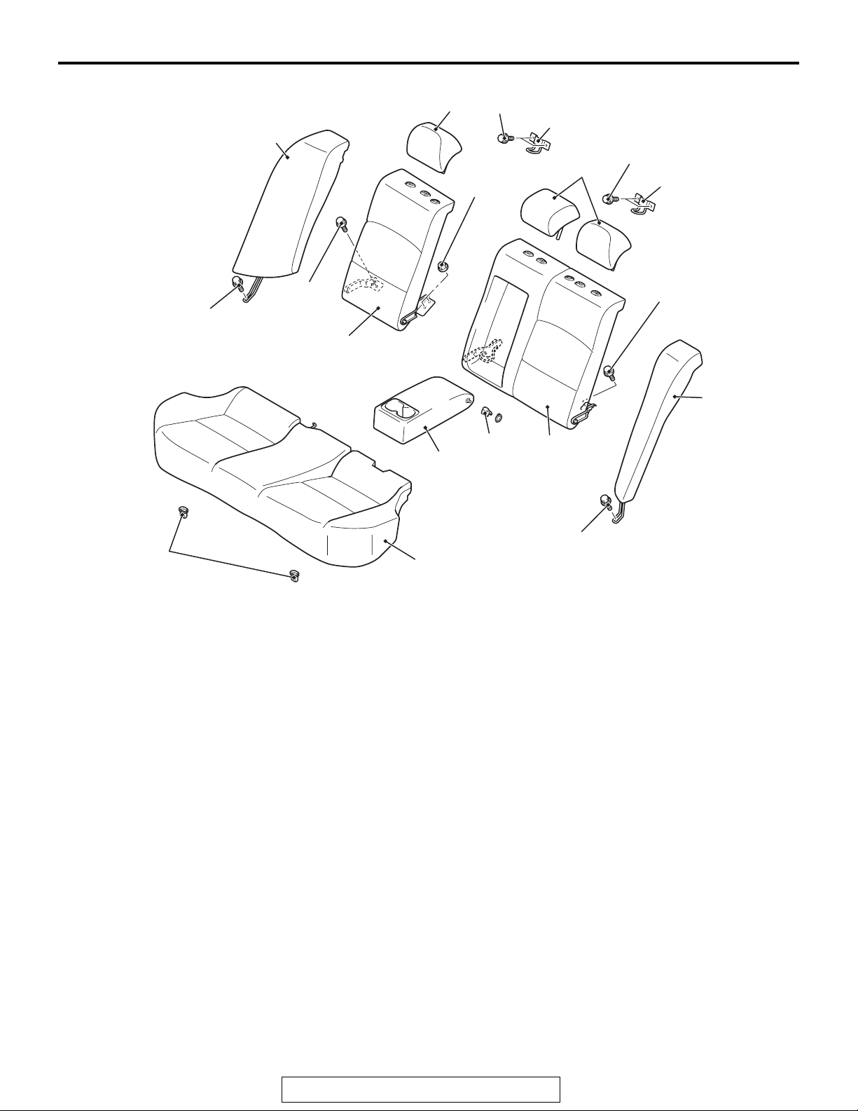
52A-24
INTERIOR
REAR SEAT ASSEMBLY
<Sprit seat>
43 ± 8 N·m
32 ± 6 ft-lb
4
43 ± 8 N·m
32 ± 6 ft-lb
21 ± 4 N·m
15 ± 3 ft-lb
1
10
21 ± 4 N·m
15 ± 3 ft-lb
38 ± 13 N·m
28 ± 10 ft-lb
1
10
43 ± 8 N·m
32 ± 6 ft-lb
6
5
8
7
9
>>C<<
>>B<<
>>B<<
>>A<<
3
Removal steps
1. Rear seat head restraint
2. Rear seat cushion assembly
3. Rear seat hook
4. Rear seatback side assembly (RH)
5. Rear seatback side assembly (LH)
6. Rear seatback assembly (RH)
43 ± 8 N·m
32 ± 6 ft-lb
2
AB
>>A<<
AC609245
Removal steps (Continued)
7. Rear seatback assembly (LH)
8. Spacer
9. Snap ring
10. Rear seat armrest
11. Rear seat striker
TSB Revision
Page 37
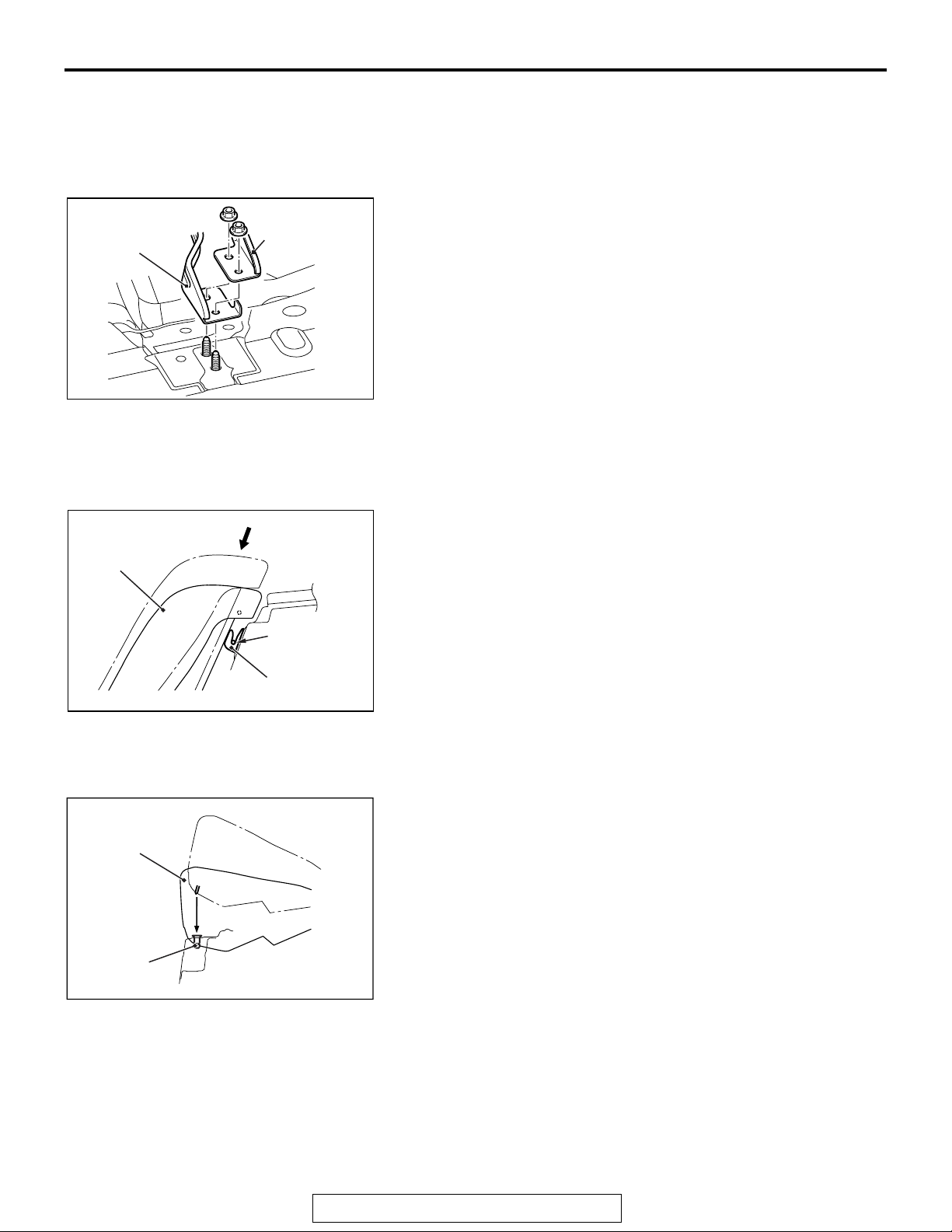
Center hinge
bracket of rear
seatback assembly
(LH)
Center hinge
bracket of rear
seatback assembly
(RH)
INTERIOR
REAR SEAT ASSEMBLY
52A-25
INSTALLATION SERVICE POINTS
.
>>A<< INSTALLATION OF REAR SEATBACK
ASSEMBLY (LH)/REAR SEATBACK ASSEMBLY
(RH)
Place the center hinge bracket of the rear seatback assembly
(LH) on top of the center hinge bracket of the rear seatback
assembly (RH) for installation.
Rear seatback
side assembly
Rear seat
cushion
assembly
AC609262
Attachment
wire
Hook
AC609261
AB
.
>>B<< INSTALLATION OF REAR SEATBACK SIDE
ASSEMBLY (LH)/REAR SEATBACK SIDE
ASSEMBLY (RH)
Press the rear seatback side assembly in the direction shown
in the illustration and fit the attachment wire into the hook
securely to install the rear seatback side assembly.
AB
.
>>C<< INSTALLATION OF REAR SEAT CUSHION
ASSEMBLY
Fit the rear seat cushion into the rear seat hook securely.
Rear seat
hook
AC609260
AB
TSB Revision
Page 38
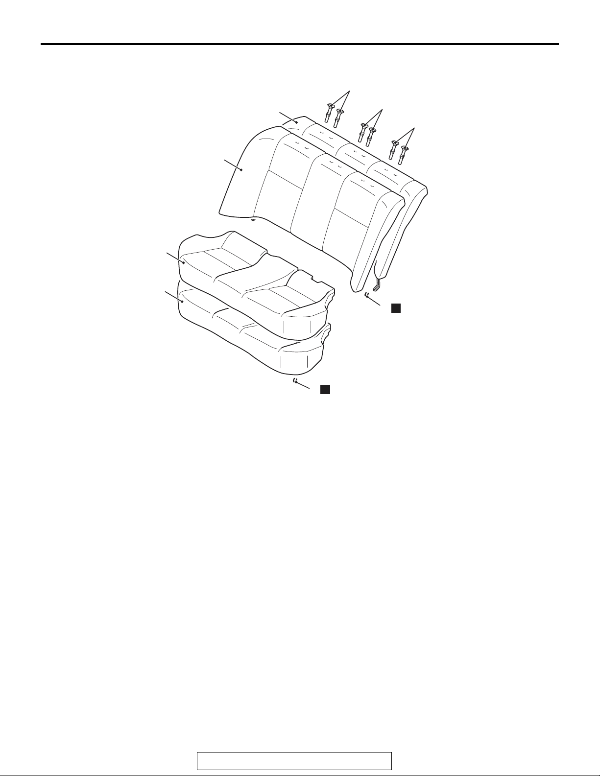
52A-26
INTERIOR
REAR SEAT ASSEMBLY
DISASSEMBLY AND ASSEMBLY
6
2
3
M1522002000766
5
7
5
5
N
4
Disassembly steps
1. Hog ring
2. Rear seat cushion cover
3. Rear seat cushion pad
4. Hog ring
N
1
AC609246
Disassembly steps (Continued)
5. Rear seat head restraint guide
6. Rear seatback cover
7. Rear seatback pad
AB
TSB Revision
Page 39
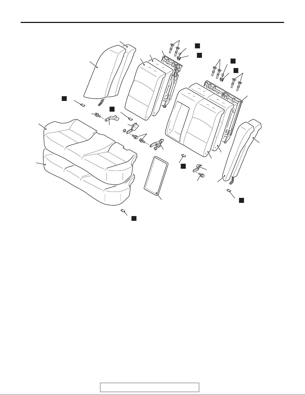
INTERIOR
REAR SEAT ASSEMBLY
52A-27
22
20
21
N
N
10
N
8
10
N
9
18
19
26
28
27
16
N
17
N
24
23
25
22 ± 4 N·m
16 ± 3 ft-lb
22 ± 4 N·m
16 ± 3 ft-lb
2
6
12
3
11
N
15
14
13
N
1
Disassembly steps
1. Hog ring
2. Rear seat cushion cover
3. Rear seat cushion pad
4. Hog ring
5. Rear seatback side cover (LH)
6. Rear seatback side pad (LH)
7. Rear seatback armrest board
8. Rear seat folding knob garnish
9. Rear seat folding knob
10. Rear seat head restraint guide
11. Hog ring
12. Center hinge bracket (LH)
13. Side hinge bracket (LH)
14. Rear seatback cover (LH)
22 ± 4 N·m
16 ± 3 ft-lb
7
15. Rear seatback pad (LH)
16. Rear seatback frame (LH)
17. Hog ring
18. Rear seatback side cover (RH)
19. Rear seatback side pad (RH)
20. Rear seat folding knob garnish
21. Rear seat folding knob
22. Rear seat head restraint guide
23. Hog ring
24. Side hinge bracket (RH)
25. Center hinge bracket (RH)
26. Rear seatback cover (RH)
27. Rear seatback pad (RH)
28. Rear seatback frame (RH)
5
N
4
AC609247
Disassembly steps (Continued)
AB
TSB Revision
Page 40
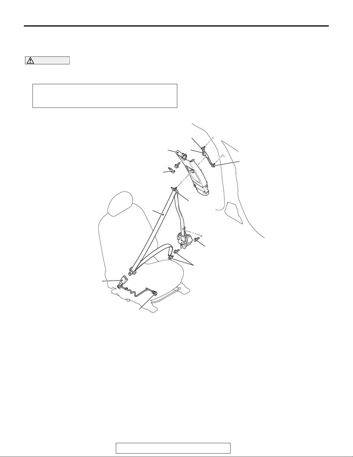
52A-28
INTERIOR
FRONT SEAT BELT
FRONT SEAT BELT
REMOVAL AND INSTALLATION
M1523001300972
CAUTION
SRS: Before removing and installing the seat belts with pre-tensioner, refer to GROUP 52B − SRS Ser-
vice Precautions P.52B-24 and Seat Belt with Pre-tensioner P.52B-393.
Pre-removal and Post-installation Operation
• Turn the ignition key to the LOOK (OFF) position.
• Disconnect the negative battery terminal.
AC608130
AC608130
43 ± 8 N·m
32 ± 6 ft-lb
2
4
43 ± 8 N·m
32 ± 6 ft-lb
1
43 ± 8 N·m
3
32 ± 6 ft-lb
<<A>>
6
5
Outer seat belt removal steps
1. Center pillar trim cup
Lower center pillar trim (Refer to
•
P.52A-10).
2. Upper center pillar trim (Refer to
P.52A-10).
3. Outer seat belt (Refer to GROUP
52B, Seat Belt with Pre-tensioner
P.52B-389).
4. Adjustable seat belt anchor
5 ± 1 N·m
44 ± 9 in-lb
43 ± 8 N·m
32 ± 6 ft-lb
Inner seat belt removal steps
5. Harness connector
Shield cover (Refer to P.52A-21).
•
6. Inner seat belt
Required Special Tool:
• MB990784: Ornament Remover
AC610305
AB
TSB Revision
Page 41
MB990784
Section A – A
INTERIOR
FRONT SEAT BELT
52A-29
REMOVAL SERVICE POINT
.
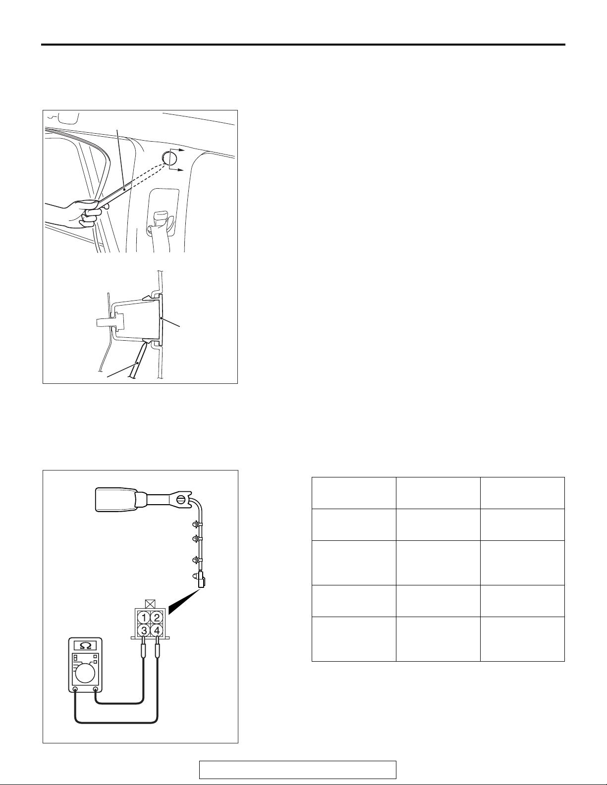
<<A>> UPPER CENTER PILLAR TRIM CAP
REMOVAL
Remove the opening trim. Remove the upper center pillar trim
cap by inserting the special tool MB990784 between the upper
center pillar trim and body as shown in the illustration.
A
A
MB990784
Upper center
pillar trim cap
AC606516
AI
INSPECTION
.
M1523004400451
SEAT BELT BUCKLE SWITCH CONTINUITY
CHECK (DRIVER’S SIDE)
Item Tester
connection
Fastened seat
1 − 2 Open circuit
belt
Unfastened
1 − 2 Continuity
seat belt
Fastened seat
3 − 4 Open circuit
belt
Specified
condition
exists (2
less)
Ω or
AC610208
TSB Revision
Unfastened
seat belt
3 − 4 Continuity
exists (2
Ω or
less)
Page 42
52A-30
INTERIOR
FRONT SEAT BELT
.
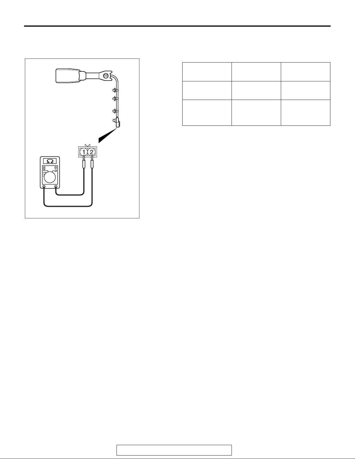
SEAT BELT BUCKLE SWITCH CONTINUITY
CHECK (PASSENGER’S SIDE)
AC610208
Item Tester
connection
Fastened seat
1 − 2 Open circuit
belt
Unfastened
1 − 2 Continuity
seat belt
Specified
condition
exists (2
Ω or
less)
TSB Revision
Page 43
INTERIOR
REAR SEAT BELT
REAR SEAT BELT
52A-31
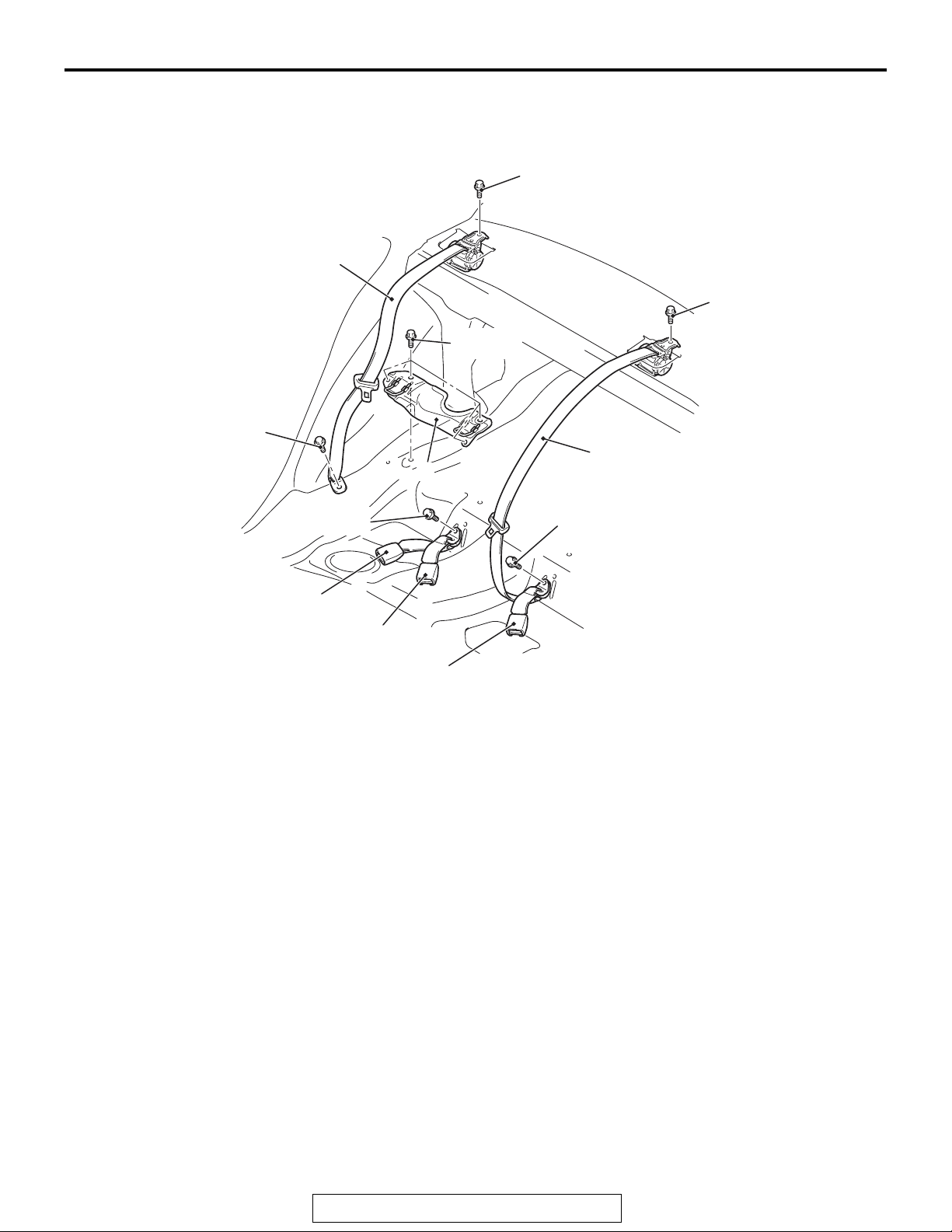
REMOVAL AND INSTALLATION
4
43 ± 8 N·m
32 ± 6 ft-lb
43 ± 8 N·m
32 ± 6 ft-lb
M1523001600810
43 ± 8 N·m
32 ± 6 ft-lb
43 ± 8 N·m
32 ± 6 ft-lb
43 ± 8 N·m
32 ± 6 ft-lb
3
5
43 ± 8 N·m
32 ± 6 ft-lb
1
2
Removal steps
Rear seat cushion assembly (Refer to
•
P.52A-23).
Rear seatback assembly (Refer to
•
P.52A-23).
Rear shelf trim (Refer to P.52A-10).
•
1
Removal steps (Continued)
1. Inner seat belt
2. Center seat belt, inner
3. Center seat belt, outer
4. Outer seat belt
5. Lower child anchor bracket
AC609742
AB
TSB Revision
Page 44

NOTES
 Loading...