

Page 1

Table of contents
General information
Locking and unlocking
Seat and seat belts
Instruments and controls
Starting and driving
For pleasant driving
Vehicle care
For emergencies
Maintenance
Specifications
Page 2
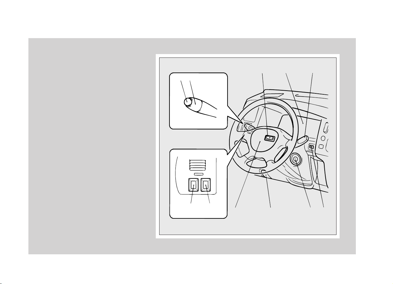
Overview - Instruments and Controls
EB21APDd
1 - Headlamp washer switch* → p. 4-17
2 - Combination headlamps, dipper and turn signal
switch → p. 4-12
3 - Rear differential lock switch* → p. 5-23
4 - Meters and gauges → p. 4-2
5 - Windscreen wiper and washer switch → p. 4-15
6 - Rear fog lamp switch* (except*1) → p. 4-19
Electric remote-controlled outside rear-view
mirrors* → p. 5-38
7 - Rheostat* → p. 4-20
Rear fog lamp switch*1→ p. 4-19
8 - Supplemental restraint system-air bag
(for driver's seat)* → p. 3-20
Horn switch → p. 4-20
9 - Bonnet release lever → p. 2-7
10 - Ignition switch → p. 5-9
11 - Headlamp levelling switch* → p. 4-14
LHD
12
67
34 5
8 9 10 11
B21A627
NOTE: *1- Vehicle with electric remote-controlled outside rear-view mirrors as
optional equipment only
Page 3
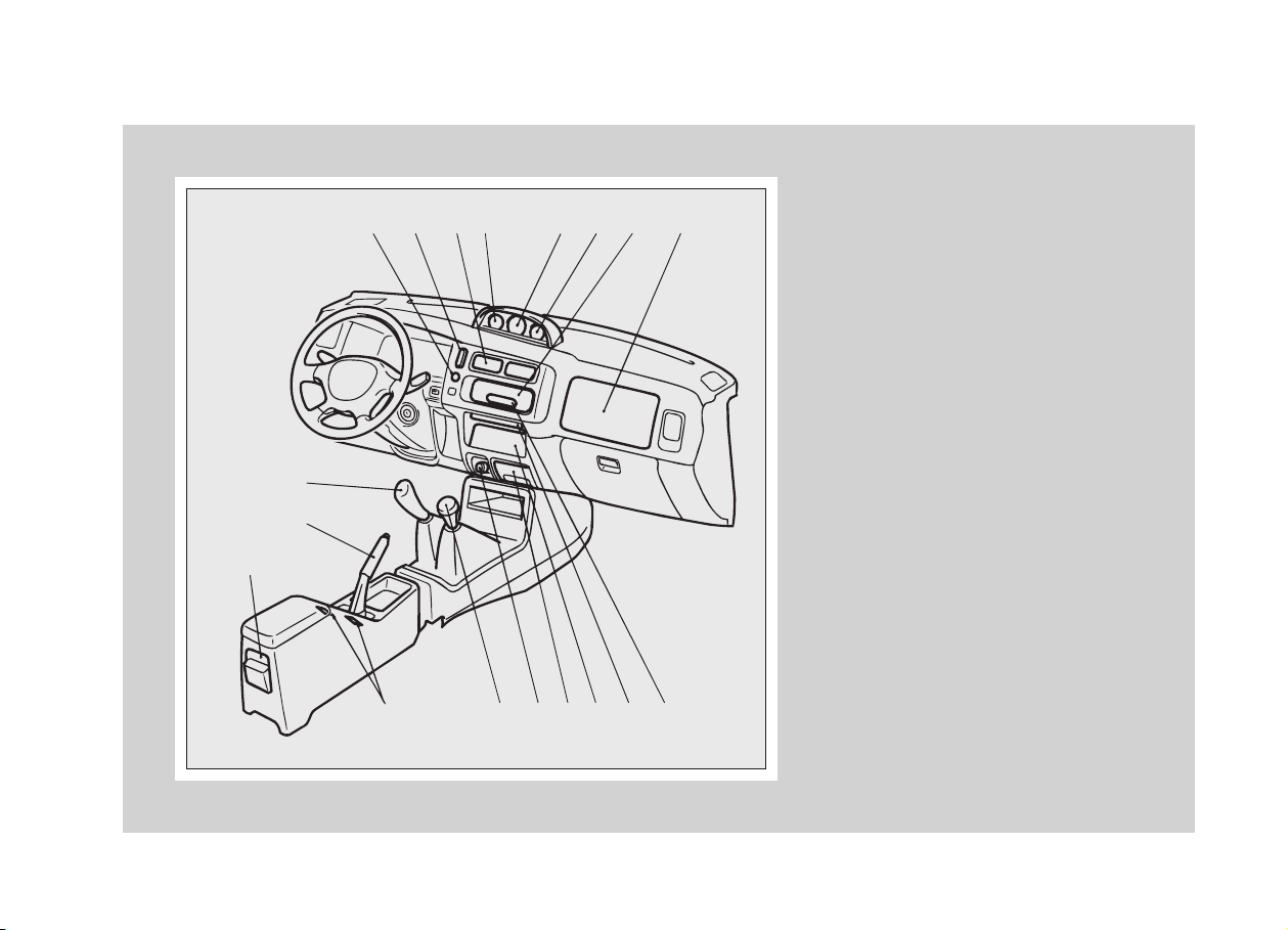
Instruments and Controls
LHD
11
9
10
21345678
12
13 14 15 16 17 18
1 - Rear window demister switch* → p. 4-18
2 - Hazard warning flasher switch → p. 4-18
3 - Ventilators → p. 6-18
4 - Inclinometer* → p. 4-4
5 - Thermometer* → p. 4-5
6 - Voltage meter* → p. 4-5
7 - Heater/Air conditioning* → p. 6-19, p. 6-25
8 - Supplemental restraint system-air bag*
(for front passenger's seat) → p. 3-20
9 - Gearshift lever or selector lever → p. 5-14, p. 5-16
10 - Parking brake lever → p. 5-30
11 - Rear heater* → p. 6-30
12 - Heated seat switch* → p. 3-7
13 - Transfer shift lever (4WD only) → p. 5-20
14 - Cigarette lighter → p. 6-33
15 - Ashtray → p. 6-34
16 - Audio* → p. 6-2
17 - Cup tray → p. 6-37
18 - Digital clock → p. 6-34
B21A474
Page 4
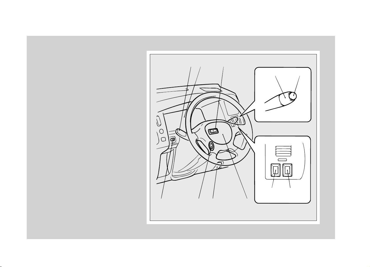
Instruments and Controls
1 - Windscreen wiper and washer switch → p. 4-15
2 - Meters and gauges → p. 4-2
3 - Rear differential lock switch* → p. 5-23
4 - Combination headlamp, dipper and turn signal
switch → p. 4-12
5 - Headlamp washer switch* → p. 4-17
6 - Headlamp levelling switch* → p. 4-14
7 - Ignition switch → p. 5-9
8 - Bonnet release lever → p. 2-7
9 - Supplemental restraint system-air bag
(for driver's seat)* → p. 3-20
Horn switch → p. 4-20
10 - Rheostat* → p. 4-20
Rear fog lamp switch*1→ p. 4-19
11 - Rear fog lamp switch (except*1) → p. 4-19
Electric remote-controlled outside rear-view
mirrors* → p. 5-38
RHD
12 3
45
10 11
6789
B21A624
NOTE: *1- Vehicle with electric remote-controlled outside rear-view mirrors as
optional equipment only
Page 5
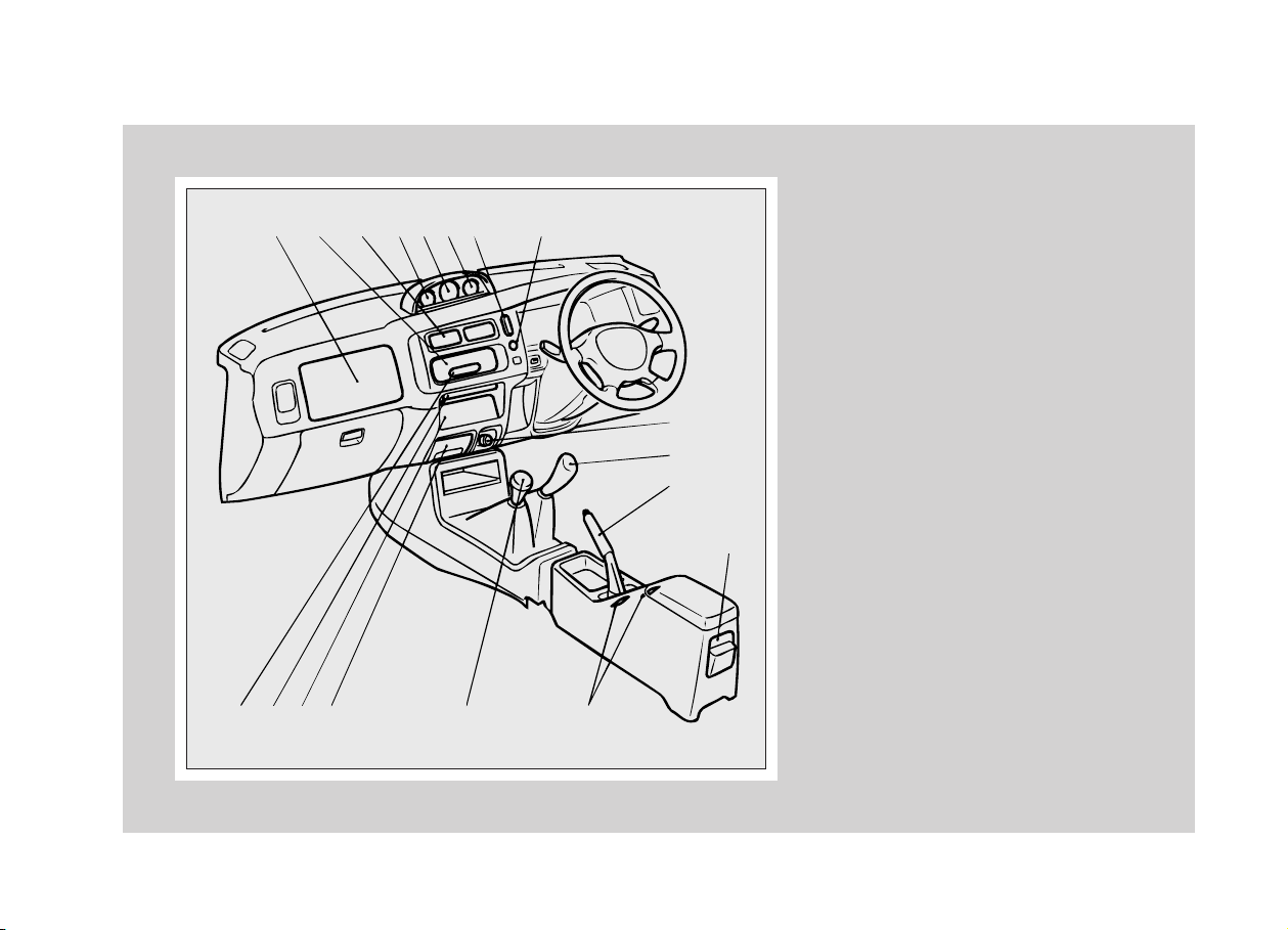
Instruments and Controls
RHD
1234567 8
9101112 13 14
18
17
16
15
B21A625
1 - Supplemental restraint system-air bag
(for front passenger's seat)* → p. 3-20
2 - Heater/Air conditioning* → p. 6-19
3 - Ventilators → p. 6-18
4 - Voltage meter* → p. 4-5
5 - Thermometer* → p. 4-5
6 - Inclinometer* → p. 4-4
7 - Hazard warning flasher switch → p. 4-18
8 - Rear window demister switch* → p. 4-18
9 - Digital clock → p. 6-34
10 - Cup tray → p. 6-37
11 - Audio* → p. 6-2
12 - Ashtray → p. 6-34
13 - Transfer shift lever (4WD only) → p. 5-20
14 - Heated seat switch* → p. 3-7
15 - Rear heater* → p. 6-30
16 - Parking brake lever → p. 5-30
17 - Gearshift lever → p. 5-14
18 - Cigarette lighter → p. 6-33
NOTE: *1- Vehicle with electric remote-controlled outside rear-view mirrors as
optional equipment only
Page 6
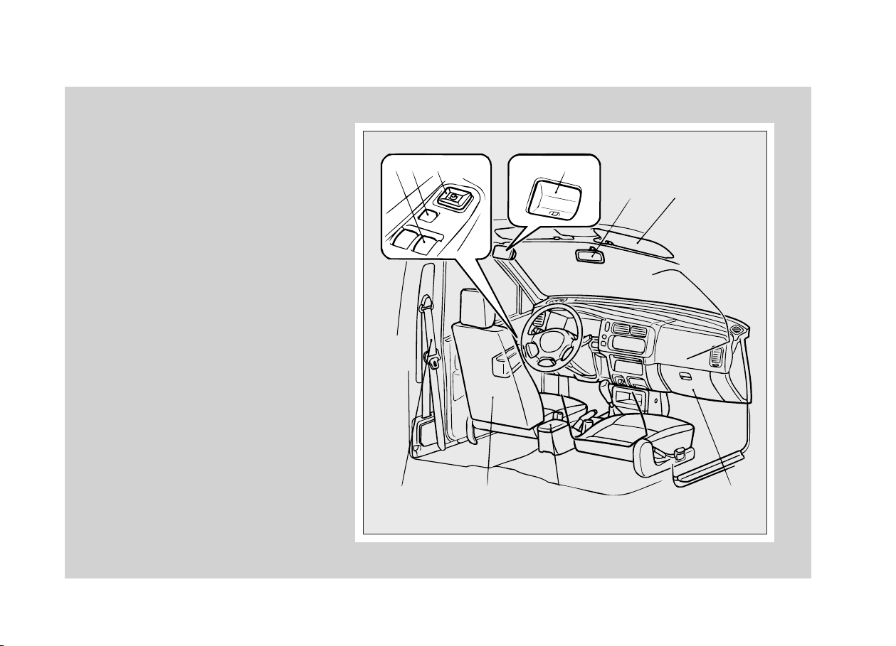
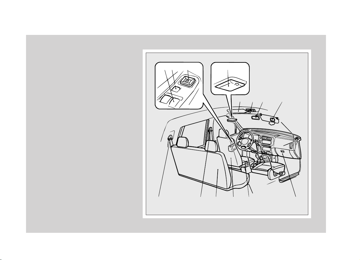
Interior (Single cab)
EB21BPDe
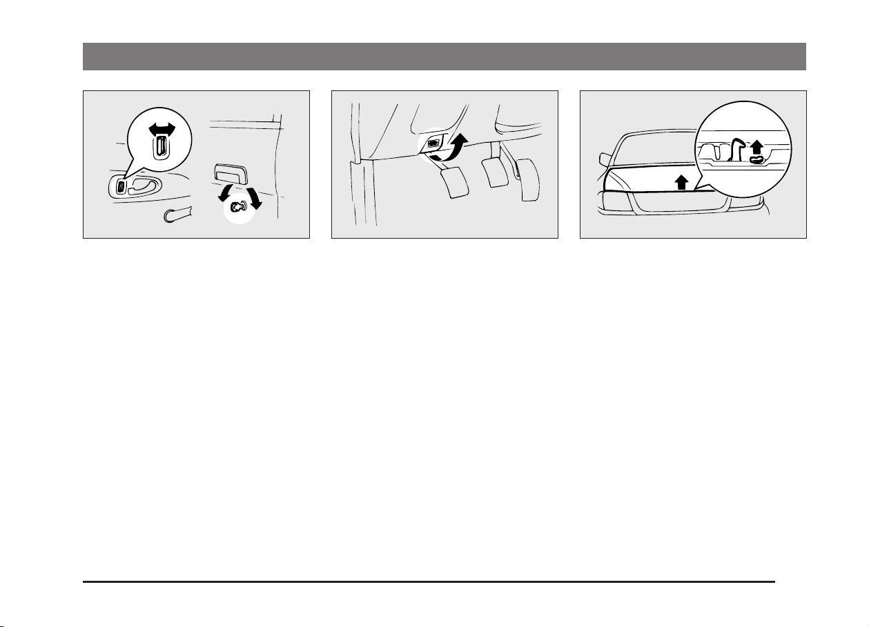
1 - Electric window control* → p. 2-9
2 - Lock switch* → p. 2-10
3 - Electric remote-controlled outside rear-view
mirror* → p. 5-38
4 - Room lamp → p. 4-20
5 - Inside rear-view mirror → p. 5-37
6 - Sun visor → p. 6-32
7 - Seat belt → p. 3-8
8 - Seat → p. 3-2
9 - Centre console box* → p. 6-36
10 - Glove box → p. 6-35
LHD
12 3
4
56
789 10
B21B519
Page 7
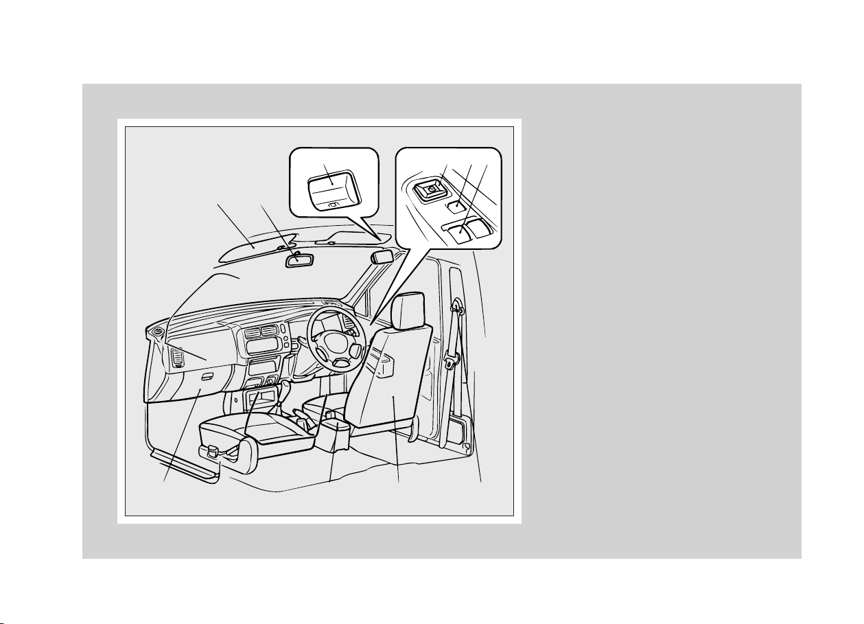
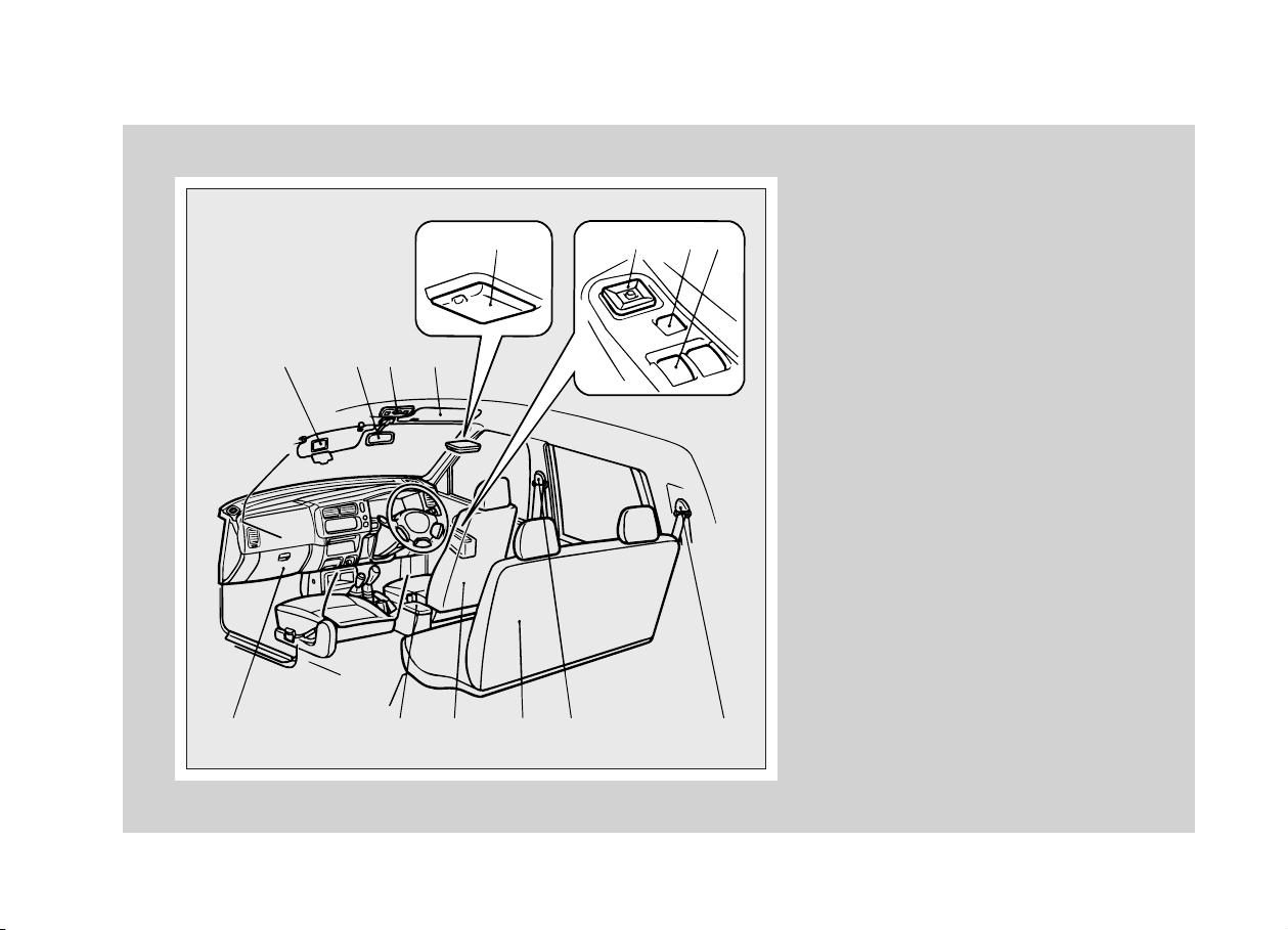
Interior (Single cab)
RHD
3456
12
1 - Sun visor → p. 6-32
2 - Inside rear-view mirror → p. 5-37
3 - Room lamp → p. 4-20
4 - Electric remote-controlled outside rear-view
mirror* → p. 5-38
5 - Lock switch* → p. 2-10
6 - Electric window control* → p. 2-9
7 - Glove box → p. 6-35
8 - Centre console box* → p. 6-36
9 - Seat → p. 3-2
10 - Seat belt → p. 3-8
78910
B21B520
Page 8
Interior (Club cab)
1 - Electric window control* → p. 2-9
2 - Lock switch* → p. 2-10
3 - Electric remote-controlled outside rear-view
mirror* → p. 5-38
4 - Room lamp → p. 4-20
5 - Sun visor → p. 6-32
6 - Personal lamp* → p. 4-21
7 - Inside rear-view mirror → p. 5-37
8 - Vanity mirror* → p. 6-32
9 - Seat belt → p. 3-8
10 - Adjustable seat belt anchor (for front seats)
→ p. 3-11
11 - Front seat → p. 3-3
12 - Rear seat → p. 3-5
13 - Secret box → p. 6-37
14 - Centre console box* → p. 6-36
15 - Glove box → p. 6-35
LHD
123 4
8765
91011121314 15
B21B541
Page 9
Interior (Club cab)
RHD
5678
1234
9101112131415
B21A344
B21B542
1- Vanity mirror* → p. 6-32
2- Inside rear-view mirror → p. 5-37
3- Personal lamp* → p. 4-21
4- Sun visor → p. 6-32
5- Room lamp → p. 4-20
6- Electric remote-controlled outside rear-view
mirror* → p. 5-38
7- Lock switch* → p. 2-9
8- Electric window control* → p. 2-9
9- Glove box → p. 6-35
10- Centre console box* → p. 6-36
11- Rear seat → p. 3-5
12- Front seat → p. 3-3
13- Adjustable seat belt anchor (for front seats)
→ p. 3-11
14- Secret box → p. 6-37
15- Seat belt → p. 3-8
Page 10
Interior (Double cab)
1 - Electric window control* → p. 2-9
2 - Lock switch* → p. 2-10
3 - Electric remote-controlled outside rear-view
mirror* → p. 5-38
4 - Room lamp → p. 4-20
5 - Sun visor → p. 6-32
6 - Personal lamp* → p. 4-21
7 - Inside rear-view mirror → p. 5-37
8 - Vanity mirror* → p. 6-32
9 - Seat belt → p. 3-8
10 - Adjustable seat belt anchor (for front seats)
→ p. 3-11
11 - Rear seat → p. 3-5
12 - Front seat → p. 3-3
13 - Centre console box* → p. 6-36
14 - Glove box → p. 6-35
LHD
12 3 4
567 8
910111213 14
B21A342
B21B522
Page 11
Interior (Double cab)
RHD
5678
1234
1 - Vanity mirror* → p. 6-32
2 - Inside rear-view mirror → p. 5-37
3 - Personal lamp* → p. 4-21
4 - Sun visor → p. 6-32
5 - Room lamp → p. 4-20
6 - Electric remote-controlled outside rear-view
7 - Lock switch* → p. 2-10
8 - Electric window control* → p. 2-9
9 - Glove box → p. 6-35
10 - Centre console box* → p. 6-36
11 - Front seat → p. 3-3
12 - Rear seat → p. 3-5
13 - Adjustable seat belt anchor (for front seats)
14 - Seat belt → p. 3-8
91011121314
B21A344
B21B523
mirror* → p. 5-38
→ p. 3-11
Page 12
Exterior (Single cab, Club cab)
1 - Rear gate → p. 2-12
2 - High-mounted stop lamp* → p. 8-34, 8-38
3 - Electric window control* → p. 2-9
4 - Engine compartment → p. 10-25
5 - Bonnet → p. 2-7
6 - Windscreen wiper and washer → p. 4-15
7 - Antenna → p. 6-18
8 - Door mirrors → p. 5-37
9 - Locking and unlocking → p. 2-4
Keyless entry system* → p. 2-5
10 - Fuel filler → p. 5-3
11 - Rear fog lamp (Driver’s side only)*
→ p. 4-19, 8-34, 8-38
12 - Number-plate lamps → p. 4-12, 8-34, 8-37
13 - Stop and tail lamps → p. 8-34, 8-37
14 - Reversing lamps → p. 8-34, 8-37
15 - Rear turn-signal lamps → p. 4-13, 8-34, 8-37
16 - Headlamps → p. 4-12, 8-35
17 - Front turn-signal lamps → p. 4-13, 8-34, 8-36
18 - Position lamps → p. 4-12, 8-34, 8-36
19 - Tyre chains → p. 9-13
Tyre rotation → p. 9-11
Changing tyres → p. 8-16
Tyre inflation pressure → p. 9-11
20 - Side turn-signal lamps → p. 4-13, 8-34, 8-36
A- Single Cab
B- Club Cab
1
A
B
2
11 12 11 13 14 15 16 17 18 19 20
12
11 12 13 14 15 16 17 18 19 20
4
3
5
4
3
5
678910
678910
B21A342
A02A279
EB21DPDf
Page 13
1
236789104
5
11 12 11 13 14 15 16 17 18 19 20
Exterior (Double cab)
1 - Rear gate → p. 2-12
2 - High-mounted stop lamp* → p. 8-34, 8-38
3 - Electric window control* → p. 2-9
4 - Engine compartment → p. 10-25
5 - Bonnet → p. 2-7
6 - Windscreen wiper and washer → p. 4-15
7 - Antenna → p. 6-18
8 - Door mirrors → p. 5-37
9 - Locking and unlocking → p. 2-4
Keyless entry system* → p. 2-5
10 - Fuel filler → p. 5-3
11 - Rear fog lamp (Driver’s side only)*
→ p. 4-19, 8-34, 8-38
12 - Number-plate lamps → p. 4-12, 8-34, 8-37
13 - Stop and tail lamps → p. 8-34, 8-37
14 - Reversing lamps → p. 8-34, 8-37
15 - Rear turn-signal lamps → p. 4-13, 8-34, 8-37
16 - Headlamps → p. 4-12, 8-35
17 - Front turn-signal lamps → p. 4-13, 8-34, 8-36
18 - Position lamps → p. 4-12, 8-34, 8-36
19 - Tyre chains → p. 9-13
Tyre rotation → p. 9-11
Changing tyres → p. 8-16
Tyre inflation pressure → p. 9-11
20 - Side turn-signal lamps → p. 4-13, 8-34, 8-36
B21A344
A02A280
Page 14

GENERAL INFORMATION
Installation of accessories
EB24A-E
Before fitting any accessories, please consult your authorized MITSUBISHI dealer.
(1) The installation of accessories, op-
tional parts, etc., should only be carried out within the limits prescribed by
law in your country, and in accordance with the guidelines and warnings contained within the documents
accompanying this vehicle.
Only MITSUBISHI approved accessories should be fitted to your vehicle.
(2) Improper installation of electrical
parts could cause fire, please refer to
the Modification/Alteration to the electrical or fuel systems section within
this manual.
(3) When using a communication system
such as a cellular phone or a radio set
inside the vehicle, a separate external
antenna must be fitted. When a
cellular phone or a radio set is used
by using an internal antenna alone, it
may interfere with the vehicle’s electrical system and adversely affect
safe operation of the vehicle.
(4) Tyres and wheels which do not meet
specifications must not be used.
Refer to the “Specification” section for
information regarding wheel and tyre
sizes.
1-14
(5) Do not fail to read all relative instruc-
tions before first putting into service
the attachment or installation of
accessories, parts or other modifications to the vehicle!
Important points!
Due to the large number of accessory and
replacement parts of different manufacturers in the market, it is not possible, not
only for MITSUBISHI, but also for an authorized MITSUBISHI dealer, to check
whether the attachment or installation of
such parts affects the driving safety of
your MITSUBISHI-vehicle.
Even when such parts are officially authorized, for example by a general operators “permit” (an appraisal for the part) or
through the execution of the part in an officially approved manner of construction, or
when a single operation permit following
the attachment or installation of such
parts, it cannot be deduced from that
alone, that the driving safety of your vehicles has not been affected.
Consider also that there basically exists
no liability on the part of the appraiser
or the official. Only in the case of parts
(MITSUBISHI original replacement or exchange parts as well as MITSUBISHI
accessories) that are recommended and
released by an authorized MITSUBISHI
dealer and that are attached or installed
by an authorized MITSUBISHI dealer can
you assume, that optimal safety has been
provided. The same also pertains to modifications of MITSUBISHI vehicles with respect to the production specifications. For
your own safety, in such cases as well,
you should only undertake modifications
according to the recommendations of an
authorized MITSUBISHI dealer.
Page 15
GENERAL INFORMATION
Modification / alterations
to the electrical or fuel
systems
MITSUBISHI has always manufactured
safe, high quality vehicles. In order to
maintain this safety and quality, it is important that any accessory that is to be fitted,
or any modifications that are to be carried
out which involve the electric or fuel systems, should be carried out in accordance
with MITSUBISHI guidelines.
EB11A-D
CAUTION
Please consult an authorized MITSUBISHI dealer concerning any
such fitment or modification.
If the wires interfere with the vehicle
body or if improper installation
methods are used (protective fuses
not included, etc.), electronic devices may be adversely affected, resulting in fire or an other accident.
B
A
B10A013
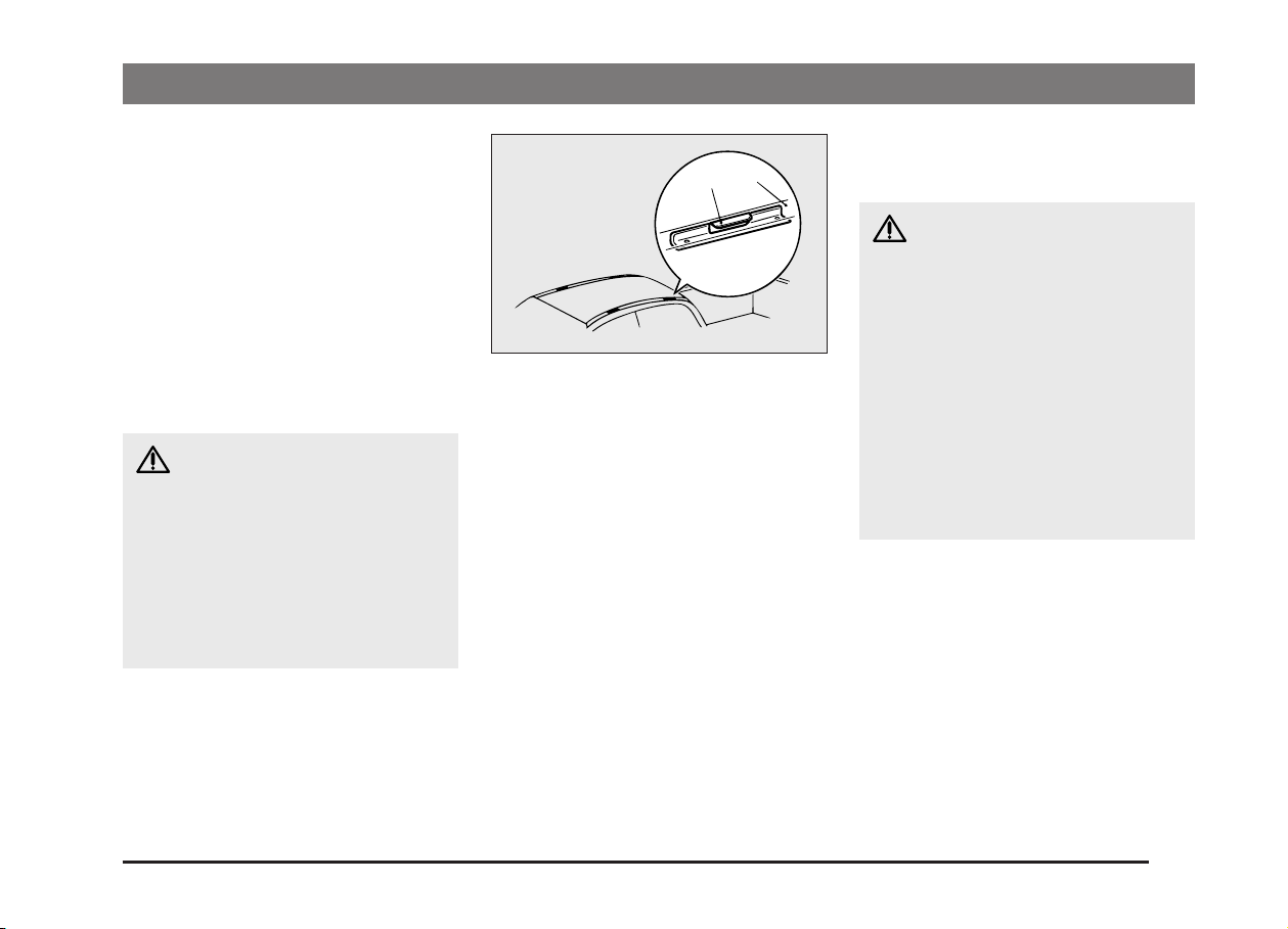
Roof drip moulding*
When installing the roof rack, use the
brackets (A).
There are brackets (A) under roof drip
moulding (B).
NOTE
(1) Use a genuine MITSUBISHI roof car-
rier, since the brackets to be used are
of special shape. For details, consult
a nearby authorized MITSUBISHI
dealer.
(2) For the roof load, refer to page 10-6,
10-12, 10-19.
EB10A-Fb
Roof carrier precaution
EB10A-S
CAUTION
(1) Make sure that the weight of the
luggage does not exceed the allowable roof load.
If the allowable roof load is exceeded, this may cause damage
to the vehicle.
The roof load is the total allowable load on the roof (the weight
of the roof carrier plus the
weight of luggage placed on the
roof carrier).
For specific figures, please refer
to the “Maximum roof load” on
page 10-6, 10-12, 10-19.
1-15
Page 16
GENERAL INFORMATION
CAUTION
(2) When luggage is loaded onto
the vehicle, please make sure to
drive slowly and avoid excessive manoeuvres such as sudden braking or quick turning.
In addition, place the luggage on
the carrier so that its weight is
distributed evenly with the heaviest items on the bottom. Do not
load items that are wider than
the roof carrier.
The additional weight on the
roof could heighten the vehicle’s centre of gravity and affect
the vehicle's handling characteristics.
As a result, driving errors or
emergency manoeuvres could
lead to loss of control and result
in an accident.
(3) Before driving and after travel-
ling a short distance, always
check the load to make sure it is
securely fastened to the roof
carrier. Check periodically during your travel that the load remains secure. If the load is not
secure, it could fall from the vehicle and damage your vehicle,
another vehicle or create road
hazard.
NOTE
(1) To prevent wind noise or reduction in
gas mileage, remove the roof carrier
when not in use.
(2) Before using an automatic car wash,
check with the attendant to determine
if the roof carrier should be removed.
Genuine parts
Don’t play around with substitutes.
MITSUBISHI has gone to great lengths to
bring you a superbly crafted vehicle offering the highest quality and dependability.
Don’t reduce that quality and dependability
by using substitute parts.
Always use MITSUBISHI Genuine Parts
designed and manufactured to maintain
your MITSUBISHI vehicle at top performance. The operation of vehicle components can be less efficient in case of using
Non-Genuine Parts.
Failure to use Genuine Parts, may invalidate any future warranty claim.
MITSUBISHI will not be liable for any malfunction of your vehicle that may have
been caused by the use of substitute parts
in place of MITSUBISHI Genuine Parts.
At the MITSUBISHI dealer you can also
get appropriate advise and the assembling of Genuine Parts will be handled professionally.
MITSUBISHI Genuine Parts are identified
by this mark, and are available at all authorized MITSUBISHI dealers.
EB05A-Fi
1-16
Page 17
GENERAL INFORMATION
Used engine oils safety
instructions
EB12A-A
WARNING
(1) Prolonged and repeated contact
may cause serious skin disorders, including dermatitis and
cancer.
(2) Avoid contact with the skin as
far as possible and wash thoroughly after any contact.
(3) Keep out of reach of children.
Protect the environment
It is illegal to pollute drains, water courses
and soil. Use authorized waste collection
facilities, including civic amenity sites and
garages providing facilities for disposal of
used oil and used oil filters. If in doubt,
contact your local authority for advice on
disposal.
Driving and alcohol
Driving under the influence of alcohol is
one of the most frequent causes of accidents.
Your driving ability can even be seriously
impaired with blood alcohol levels below
the legal minimum. If you are drinking,
don’t drive. Ride with a designated nondrinking driver, call a cab, a friend, or use
public transportation.
EB25A-Aa
WARNING
Driving after drinking can lead to an
accident. Your perceptions are less
sharp, your reflexes are slower, and
your judgement is impaired when
you have been drinking.
NEVER DRINK AND THEN DRIVE.
Safe driving techniques
EB26A-Cb
Driving safety and protection against injury cannot be fully ensured. However, we
recommend that you pay extra attention to
the following:
(1) Before starting the vehicle, make sure
that you and your passengers have
fastened your seat belts.
(2) Never leave your vehicle unattended
with the key in the ignition and
children inside the vehicle. Children
may play with the driving controls and
this could lead to an accident.
(3) Make sure that infants and small chil-
dren are properly restrained in accordance with the laws and regulations,
and for maximum protection in case
of an accident.
1-17
Page 18

GENERAL INFORMATION
(4) Switch off the engine if you stop for a
short sleep. If the engine is left running while you sleep, unexpected vehicle operation or other accidents
may be caused by unconsciously
moving the shift lever (selector lever
on automatic transmission vehicles)
or pressing the accelerator pedal. If
you inadvertently keep the accelerator pedal pressed, the engine may
overheat or the engine, exhaust pipe,
etc. may be abnormally overheated,
resulting in an accidental fire. If poorly
ventilated, there is a risk of poisoning
by exhaust gases.
1-18
Page 19

Locking and unlocking
Keys .............................................................. 2-2
Electronic immobilizer
(Anti-theft starting system)*.................. 2-2
Doors............................................................. 2-4
Keyless entry system*................................. 2-5
“Child-protection” rear doors
(Double cab) ........................................... 2-6
Central door locks* ...................................... 2-7
Bonnet........................................................... 2-7
Manual window control*.............................. 2-9
Electric window control* ............................. 2-9
Quarter window (Club cab) ......................... 2-11
Rear gate....................................................... 2-12
2
Page 20
LOCKING AND UNLOCKING
1
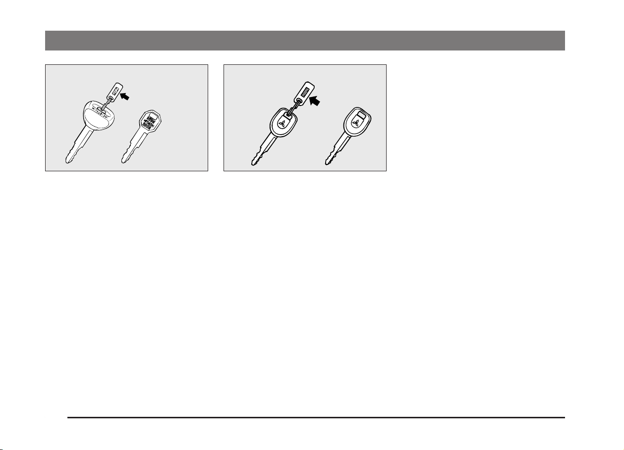
Keys
2
F11A034
EF21ABM
Without an electronic immobilizer
(Type 1)
1 - Master key
2 - Sub key*
With an electronic immobilizer
(Type 2)
3 - Master key (Black)
4 - Sub key (Grey)*
Two master keys are provided. They fit all
locks. Keep one in a safe place as a spare
key.
One sub key is provided (for some models). It fits all locks except for the glove
box.
Type 2Type 1
34
F11A090
NOTE
(1) The key number is stamped on the
tag as indicated in the illustration.
Make a record of the key number and
store the key and key number tag
in separate places, so that you can
order a key from your authorized
MITSUBISHI dealer in the event the
original keys are lost.
(2) If your vehicle is equipped with an
electronic immobilizer, the engine is
designed so that it will not start if the
ID code registered in the immobilizer
computer and the key’s ID code do
not match. Refer to the section entitled “Electronic Immobilizer” for
details and key usage.
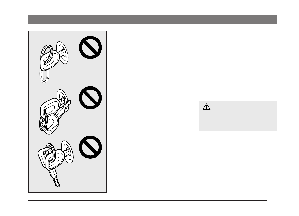
(3) Keys should never be placed in areas
which contain magnetic or metal objects as this may interfere with the
transponder.
Electronic immobilizer
(Anti-theft starting system)*
EF11CPD
The electronic immobilizer is designed to
reduce significantly the possibility of vehicle theft. The purpose of the system is to
immobilize the vehicle if an invalid start is
attempted. A valid start attempt can only
be achieved (subject to certain conditions), using a key “registered” to the immobilizer system.
2-2
Page 21
LOCKING AND UNLOCKING
NOTE
A
B
C
(1) In the following cases the vehicle may
not be able to receive the registered
ID code from the key. This means the
engine will not start even when the
registered key is turned to the
“START” position:
• When the key contacts a key ring or
other metallic or magnetic object
(Type A)
• When the key grip contacts metal of
another key (Type B)
• When the key contacts another immobilizing key, or some other
transponder (Type C)
In cases like these, remove the above
object from the key and turn the key
back to the “ACC” or “LOCK” position.
Then try again to start the engine.
If the engine does not start, consult an
authorized MITSUBISHI dealer.
(2)
Be careful not to damage the key with a
cutter etc. since there is a transponder
inside the key
.
(3) If you lose your keys, order a key from
your authorized MITSUBISHI dealer
as soon as possible.
To obtain a key, take your vehicle and
any remaining key to your authorized
MITSUBISHI dealer.
If you need an extra spare key, take
your vehicle and ALL the keys to your
authorized MITSUBISHI dealer.
All the keys have to be re-registered
in the immobilizer computer unit.
The immobilizer allows up to 8 different ID codes to be registered; you can
possess a maximum of 8 keys.
CAUTION
Do not make any alterations or additions to the immobilizer system, alterations or additions could cause
failure of the immobilizer.
F11C003
2-3
Page 22
LOCKING AND UNLOCKING
1
2
3
F12A100
Doors
EF12AAEd
Operation from outside the vehicle
1 - Insert or remove the key
2 - Lock
3 - Unlock
4
5
F12A101
Operation from inside the vehicle
Lock knob
4 - Lock
5 - Unlock
Pull the inside door handle toward you to
open the door.
1
2
3
F12A102
To lock the front doors without
a key
Set the inside lock knob (1) to the locked
position (so that the red mark cannot be
seen) and, while pulling the outside handle up (2), close the door (3).
“Forgotten-key-prevention” mechanism
(Vehicles with keyless entry system)
If the lock knob on the driver’s door is in
the locked position and the driver’s door is
closed with the key still inserted in the ignition switch, the lock will be automatically
released.
2-4
Page 23
1
2
F12A103
To lock the rear doors (Double cab)
Set the inside lock knob (1) to the locked
position (so that the red mark cannot be
seen), and close the door (2).
CAUTION
(1) Make sure the doors are closed:
driving with doors incompletely
closed is very dangerous.
(2) Never leave children in the
vehicle unattended.
(3) Be careful not to lock the doors
while the key is inside the
vehicle.
F12D030
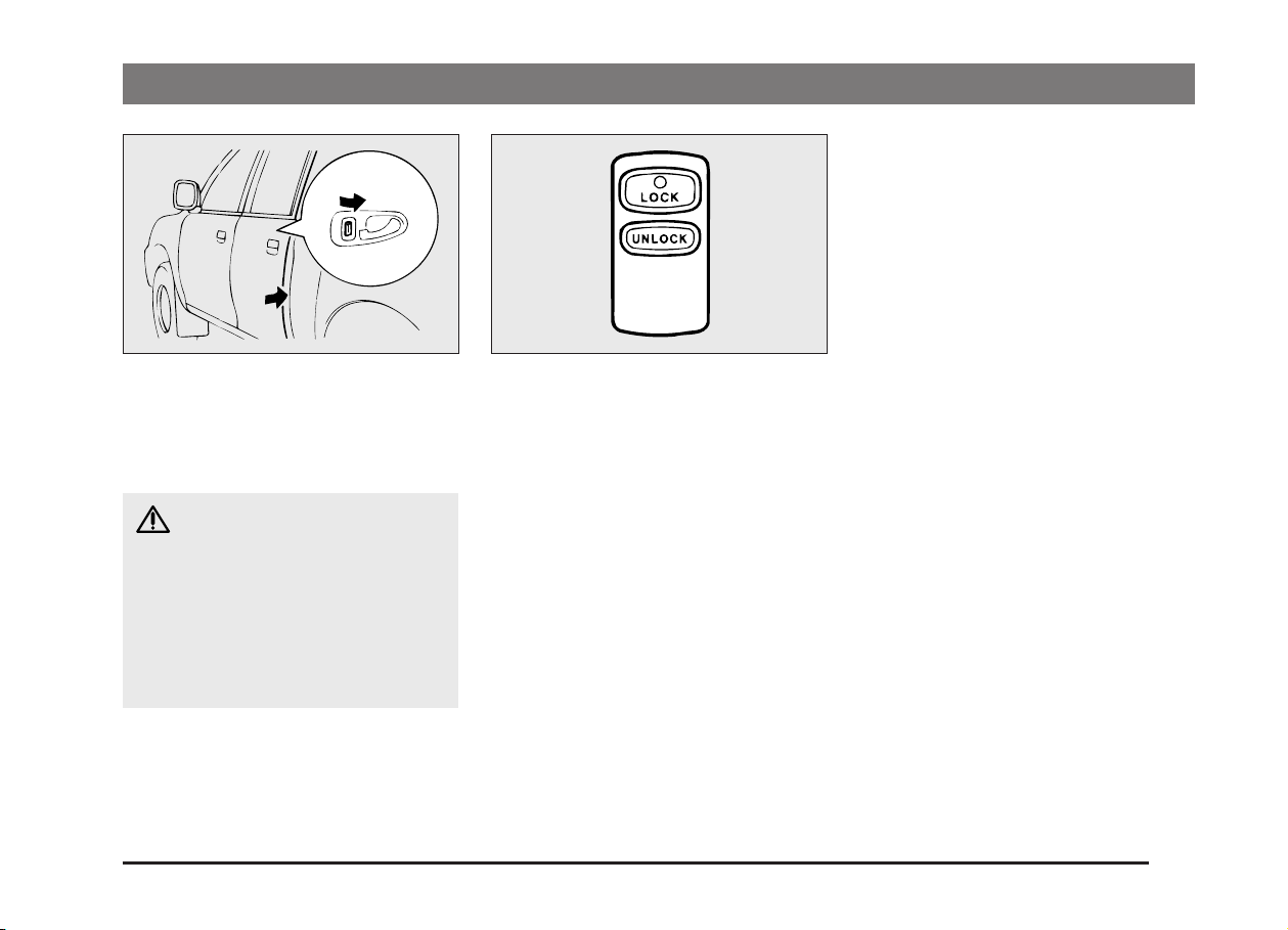
Keyless entry system*
Press the remote control switch, and all
doors will be locked or unlocked as
desired.
EF11B-Za
Operation of all doors
To lock
Press the LOCK switch, and all doors will
be locked. When they are locked with the
room lamp at the [•] position, the room
lamp and the turn-signal lamps blink
twice.
To unlock
Press the UNLOCK switch, and all doors
will be unlocked. When unlocked with the
room lamp at the [•] position, the room
lamp will be turned on for approximately
15 seconds and turn-signal lamps will
blink 4 times.
LOCKING AND UNLOCKING
NOTE
(1) The keyless entry system does not
operate if the key is left in the key
cylinder, or any door is open.
(2) If the UNLOCK switch is pressed and
no door is opened within approximately 30 seconds: relocking will
automatically occur.
(3) The remote control switch will operate
within about 4m from the vehicle.
However, the operating range of the
remote control switch may change if
the vehicle is located near a TV transmitting tower, power station, or radio
broadcasting station.
(4) If the doors cannot be locked or un-
locked after pressing the remote control switch, the battery inside the
switch may need to be replaced.
Replace the battery at your authorized MITSUBISHI dealer.
(5) If your remote control switch is lost,
please contact your authorized
MITSUBISHI dealer for a replacement remote control switch.
2-5
Page 24
LOCKING AND UNLOCKING
CAUTION
(1) Do not leave the remote control
switch where it may be exposed
to heat caused by the direct rays
of the sun.
(2) The remote control switch is a
precision electronic device.
Therefore, pay attention to the
following:
• Avoid knocking the remote
control switch hard against
other objects or dropping it.
• Keep the remote control
switch dry.
• Do not disassemble the remote control switch.
2
1
F12C016
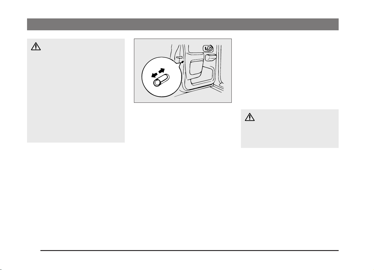
“Child-protection” rear
doors (Double cab)
1 - Lock
2 - Free
Child protection helps prevent doors from
being opened accidentally, especially
when small children are in the rear seat.
A lever is provided on each rear door.
If the lever is set to the locked position, the
rear doors cannot be opened using the
inside handle.
To open the rear door while the child protection is in use, pull the outside door handle.
If the lever is set to the “Free” position, the
child protection mechanism does not function.
EF12C-Ra
CAUTION
When driving with a child in the rear
seat, please use the child protection
to prevent accidental door opening
which may cause an accident.
2-6
Page 25
LOCKING AND UNLOCKING
1
2
1
2
F12B044
F13A085
F13A089
Central door locks*
EF02B-Wb
By locking or unlocking either the driver’s
door using the inside lock knob, or one of
the front doors (driver and passenger
side) using the key, all of the doors can be
simultaneously locked or unlocked.
1 - Lock
2 - Unlock
NOTE
(1) Each of the doors can be locked or
unlocked independently by using the
inside lock knob.
(2) Repeated continuous operating be-
tween lock and unlock could cause
the central door locking systems builtin protection circuit to prevent the system from operating. If this occurs, wait
about one minute before operating
the inside lock knob or the key.
Bonnet
EF13A-Od
To open
Pull the release lever toward you to unlock
the bonnet.
Raise the bonnet while pressing the safety
lock.
NOTE
Only open the bonnet when the wipers are
in the parked position.
Failure to do so may cause paint/body
damage.
2-7
Page 26
LOCKING AND UNLOCKING
F13A090 F13A091
Support the bonnet by inserting the support bar in its slot.
CAUTION
(1) Note that the support bar may
disengage the bonnet if the
open bonnet is lifted by a strong
wind.
(2) Always insert the support bar
into the hole provided specifically for this purpose. Supporting the bonnet at any other location could result in the support
bar slipping out and lead to an
accident.
2-8
To close
Unlatch the support bar and clip it in its
holder.
Slowly lower the bonnet to a position
30 cm above the closed position, then let
it drop.
NOTE
(1) If the bonnet does not latch, release it
from a slightly higher position.
(2) Do not press down the bonnet hard
with your hand as it may damage the
bonnet.
CAUTION
(1) Be careful that hands or fingers
are not trapped when closing
the bonnet.
(2) Before driving, make sure that
the bonnet is securely locked.
An incompletely locked bonnet
can suddenly open while driving. This can be extremely
dangerous.
Page 27
LOCKING AND UNLOCKING
1
2
F17B010
Manual window control*
EF17B-Ac
1 - To close
2 - To open
LHD
5
1
3
2
4
F17A091
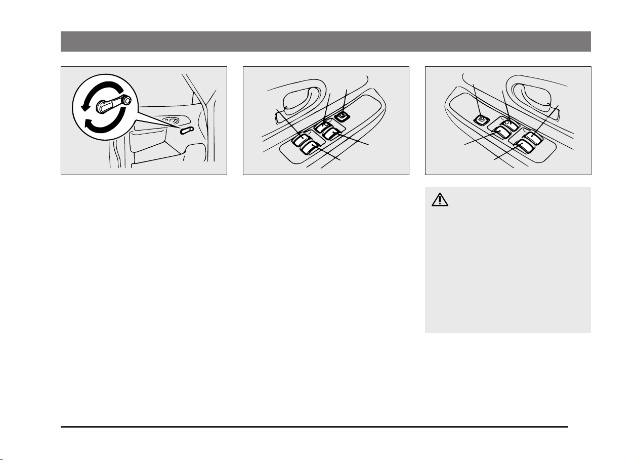
Electric window control*
EF17APD
The electric windows can only be operated with the ignition switch in the “ON”
position.
Each door window opens or closes while
the corresponding switch is operated.
1 - Driver’s door window
2 - Front passenger’s door window
3 - Rear left door window (Double cab)*
4 - Rear right door window (Double cab)*
5 - Lock switch
RHD
5
1
4
2
3
F17A094
WARNING
(1) Before operating the electric
window control, make sure that
nothing is capable of being
trapped (head, hand, finger,
etc.).
(2) Never leave the vehicle without
removing the key.
(3) Never leave a child (or other per-
son who might not be capable of
safe operation of the electric
window control switch) in the
vehicle alone.
NOTE
Repeated operation with the engine
stopped will run down the battery. Operate
the window switches only while the engine
is running.
2-9
Page 28
LOCKING AND UNLOCKING
1
2
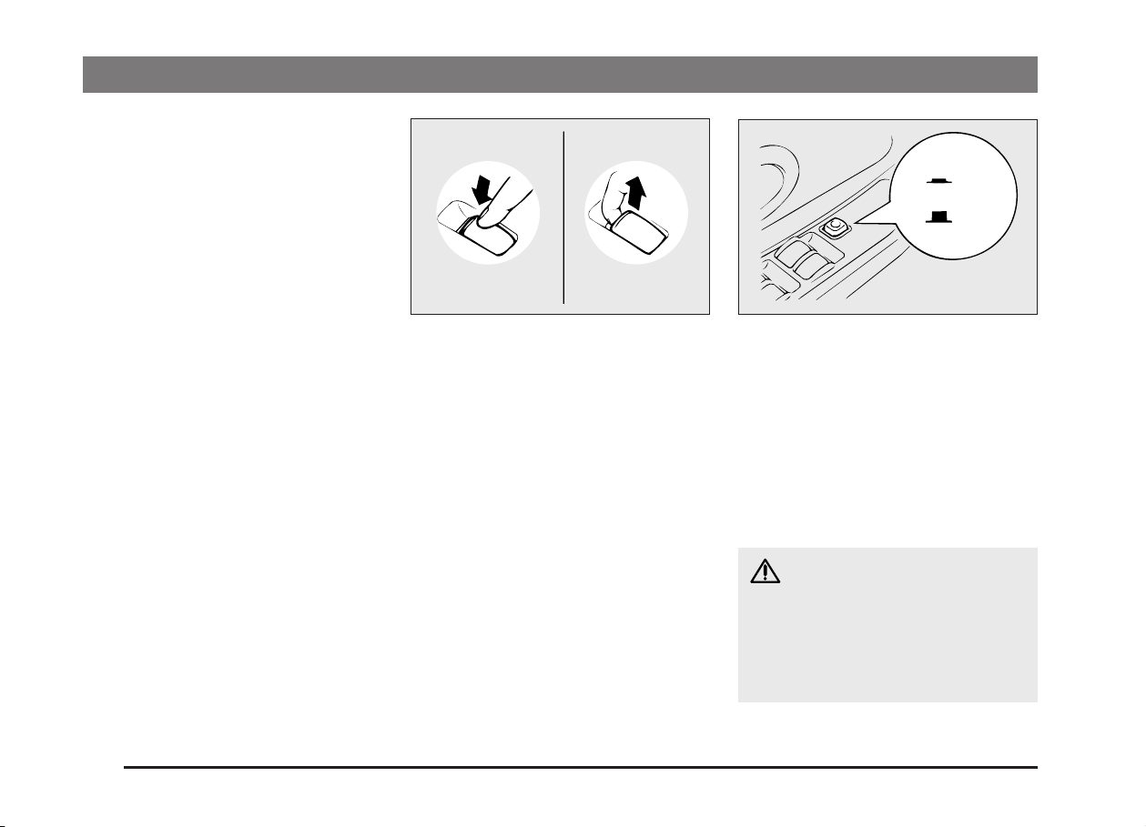
Driver’s switches
The driver’s switches can be used to operate all door windows. A window can be
opened or closed by operating the corresponding switch.
Press the switch down to open the window, and pull up the switch to close it. If
the switch for the driver’s window is fully
pressed down/pulled up, the door window
automatically opens/closes completely.
If you want to stop the window movement,
operate the switch lightly.
2-10
F17A008
Passenger’s switches
The passenger’s switches can be used to
operate the corresponding passenger’s
door windows.
Press the switch down to open, and pull
up to close.
F17A120
Lock switch
When this switch is operated, the passenger’s switches cannot be used to open or
close the door windows and the driver’s
switch cannot open or close any door windows other than the front door windows.
To unlock, press it once again.
1 - Locked
2 - Unlocked
WARNING
A child may tamper with the switch
at the risk of its hands or head being
trapped in the window. When driving
with a child in the vehicle, please
press the window lock switch to disable the passenger’s switches.
Page 29
Safety mechanism
If a hand or head is trapped in a closing
window, the window glass will lower automatically.
Nonetheless, be sure that nobody sticks
their head or hand out the window when
closing a window.
The lowered window will become operational after a few seconds.
LOCKING AND UNLOCKING
2
1
F18B005
1
2
F18B006
WARNING
The safety mechanism is cancelled
just before the window is fully
closed. This allows the window to
close completely. Therefore be especially careful that no fingers are
trapped in the window.
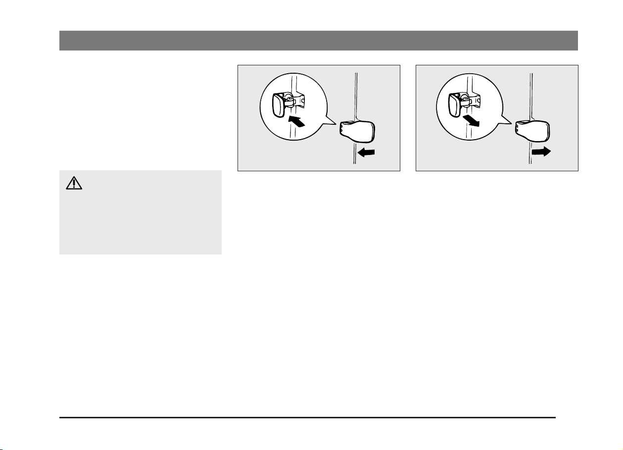
Quarter window (Club cab)
EF18B-E
To open
1. Pull the lever all the way in the direction of the arrow.
2. Press the centre of the lever to hold it
securely in place.
To close
1. Pull the centre of the lever toward
you.
2. When the window is closed, lock the
lever securely.
2-11
Page 30
LOCKING AND UNLOCKING
A
F05D008 F05D009
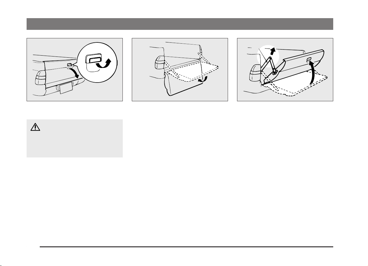
Rear gate
EF05D-Dd
CAUTION
Do not stand behind the exhaust
pipe when loading and unloading
luggage. A heat from the exhaust
could lead to burns.
To open
Lift up the handle and lower the reargate.
To close
Raise the rear gate and close with enough
force to latch the assembly securely into
position.
2-12
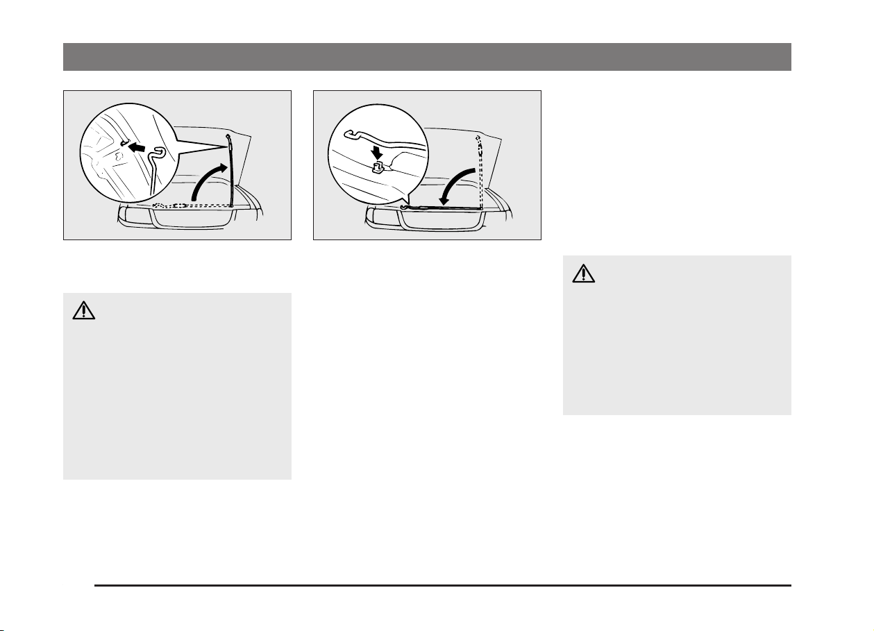
The rear gate can be swung down in two
stages. To lower it to the second stage,
proceed as follows:
F05D013
1. Swing open the rear gate to the first
position. Then, lift it up to the position
shown in the illustration while holding
the link (A).
Page 31

A
B
F05D014
2. Undo the link (A) on one side while
aligning the hole in the link with the
hook (B).
3. Undo the link on the other side in the
same manner, and have the rear gate
swing down slowly.
NOTE
Never close the rear gate with the link left
unhooked.
CAUTION
(1) Pay attention not to catch your
fingers in the rear gate or link.
(2) Do not weight the rear gate.
(3) Before driving, make sure that
the rear gate is securely locked.
If the rear gate is opened, lug-
gage could fall onto the road
and cause an accident.
LOCKING AND UNLOCKING
2-13
Page 32

Page 33

Seat and seat belts
Seat adjustment ........................................... 3-2
Front seat...................................................... 3-3
Rear seat* ..................................................... 3-5
Head restraints............................................. 3-5
Armrest*........................................................ 3-7
Heated seats* ............................................... 3-7
Seat belts ...................................................... 3-8
Child restraint............................................... 3-11
Pregnant women restraint........................... 3-20
Seat belt inspection ..................................... 3-20
Supplemental restraint system
(SRS) - air bag*....................................... 3-20
3
Page 34

SEAT AND SEAT BELTS
Seat adjustment
Adjust the driver’s seat so that you are
comfortable and that you can reach the
pedals, steering wheel, switches etc.
while retaining a clear field of vision.
EG21A-Ya
WARNING
(1) If required, always adjust the
seating before the vehicle is in
motion. After adjustments are
made, ensure the seating is
locked in position by attempting
to move the seat and seatback
forward and rearward without
using the adjusting mechanism.
(2) It is extremely dangerous to ride
in the cargo area of a vehicle.
Also, the cargo area and rear
seats should never be used as a
play area by children. In a collision, people or children riding
unrestrained in these areas are
more likely to be seriously injured or killed.
Do not allow people or children
to ride in any area of your vehicle that is not equipped with
seats and seat belts, and make
sure that everyone travelling in
your vehicle is in a seat and
wearing a seat belt, or in the
case of a child is strapped in a
child restraint.
In the interest of their safety,
children should not be allowed
to adjust the seats.
(3) To minimize the risk of personal
injury in the event of a collision
or sudden braking, both the driver and passenger seatbacks
should always be in the almost
upright position while the vehicle is in motion. The protection
provided by the seat belts may
be reduced significantly when
the seatback is reclined. There is
greater risk that the passenger
will slide under the seat belt, resulting in serious injury, when
the seatback is reclined.
CAUTION
(1) Make sure that the seat is ad-
justed by an adult.
If it is adjusted by a child, an unexpected accident might occur.
(2) Do not place a cushion or the
like between your back and
the seatback while driving. The
effectiveness of the headrestraints will be reduced in the
event of an accident.
(3) When sliding or reclining the
seat rearward, pay careful attention to the rear seat passengers.
3-2
Page 35

SEAT AND SEAT BELTS
Type 1
G21B092
Front seat
EG21B-V
To adjust forward or backward
Pull the seat adjusting lever and adjust the
seat forward or backward to the desired
position. After adjustment, release the adjusting lever to lock the seat in position.
WARNING
To ensure the seat is locked securely, try to move the seat forward
or backward without using the lever.
Type 2
G21B093
G21C117
To recline the seatback*
EG23B-Bd
In order to recline the seatback, lean forward slightly, pull the seatback lock lever
up, and then lean backward to the desired
position and release the lever. The seatback will lock in that position.
3-3
Page 36

SEAT AND SEAT BELTS
WARNING
To minimize the risk of personal injury in the event of a collision or sudden stop, both the driver and passenger seatbacks should always be
in the almost upright position while
the vehicle is in motion. The protection provided by the seat belts may
be reduced significantly when the
seatback is reclined. There is greater
risk that the passenger will slide under the seat belt, resulting in serious
injury, when the seatback is reclined.
CAUTION
The reclining mechanism of the
seatback is spring loaded, causing it
to return to the vertical position
when the lock lever is operated.
When using the lever, sit close to the
seatback or hold it with your hand.
G21H001 G01J025
Tilting the seatback forward*
1. Slide the seat all the way forward.
2. Push the lever and tilt the seatback
forward.
EG21H-Aa
2
1
To get in and out of the rear seat*
EG01J-P
The lever can be used to make getting in
and out easier.
1 - To get in or out.
2 - To get out (passenger’s seat only).
When the lever or pedal is used, the seatback wil tilt forward and at the same time
the entire seat will move forward. To return the seat, push it backward until there
is a “click” and the seat will lock in the original position.
3-4
Page 37

SEAT AND SEAT BELTS
Double cab
G02C042
Rear seat*
EG02C-R
Folding the seatback forward
(Double cab)
To fold the seatback forward, pull up the
band on the top of the seatback and fold it
forward.
Confirm that the seatback locks securely
when it is returned.
Club cab
G02C043
Folding up the seat cushion
(Club cab)
The right and left seat cushions can be
folded up separately.
To fold the seat cushions up, just raise the
seat cushions until they lock.
Confirm that the seat cushions lock
securely when they are returned.
A
G26A064
Head restraints
EG26A-Cj
Height adjustment
WARNING
(1) The head restraints can only
protect you if they are correctly
adjusted.
(2) A cushion or similar device
should not be placed on the
seatback as it may increase the
distance between your head and
the head restraint and reduce
the effectiveness of the restraint.
3-5
Page 38

SEAT AND SEAT BELTS
A
Adjust the head restraint height so that the
centre of the restraint is as close as possible to eye level to reduce the chances of
injury in the event of collision.
Any person too tall for the restraint to
reach their seated eye level, should adjust
the restraint as high as possible.
To raise the head restraint, move it upward. To lower the restraint, move it downward while pushing the height adjusting
knob (A) in the direction of the arrow. After
adjustment, push the head restraint downward and make sure that it is locked.
3-6
G26A064
Removal of head restraints
EG28BAOa
To remove the head restraints, lift the
head restraint with the height adjusting
knob (A) pushed in.
To install the head restraints, first confirm
that they are facing the correct direction,
and then insert them into the seatback
while pressing the height adjusting knobs
(A) in the direction indicated by the arrows.
G26B022
Confirm that the height adjusting knobs
(A) are correctly adjusted as shown in the
illustration and also lift the head restraints
to ensure that they do not come out of the
seatback.
WARNING
It is dangerous to drive with incorrectly adjusted head restraints or
without head restraints installed; always have them correctly fitted
when using the vehicle.
Failure to do so could cause serious
injury if involved in an accident.
Page 39

SEAT AND SEAT BELTS
3
1
2
CAUTION
If your vehicle is equipped with the
rear seat head restraint, the head restraints for the front and rear seats
differ in size.
When installing head restraints,
make sure the front and rear head restraints are fitted in their respective
seats.
Failure to do so could cause serious
injury if involved in an accident.
G27A046
Armrest*
Tilt the armrest for use as illustrated.
EG27AAA
G16A013
Heated seats*
The heated seats can only be operated
with the ignition switch in the “ON” position.
1 - Heater high (for quick heating)
2 - Heater off
3 - Heater low (to keep the seat warm)
EG16A-Ga
3-7
Page 40

SEAT AND SEAT BELTS
CAUTION
(1) Switch off seat heaters when not
in use.
(2) Operate in the high position for
quick heating. Once the seat is
warm, set the heater to low to
keep it warm. Slight variations in
the seat temperature may be felt
while using the heated seats.
This is caused by the operation
of the heater’s internal thermostat and does not indicate a malfunction.
(3) If the following types of persons
use the heated seats, they might
become too hot or receive minor
burns (red skin, heat blisters,
etc.):
• Children, elderly persons, ill
people
• People with sensitive skin
• Excessively tired people
• People under the influence of
alcohol or sleep inducing
medication (cold medicine,
etc.)
(4) Do not use a blanket, cushion,
or other material with high heat
insulation properties on the seat
while using the heater; this
might cause the heater element
to overheat.
(5) Turn the heater off immediately
if it appears to be malfunctioning during use.
NOTE
(1) Do not place heavy objects on the
seat or stick pins, needles, or other
pointed objects into it.
(2) When cleaning the seat, do not use
benzene, gasoline, alcohol, or other
organic solvents; this might damage
not only the surface of the seat, but
also the heater element.
(3) If water or any other liquid is spilled on
the seat, allow it to dry thoroughly
before attempting to use the heater.
Seat belts
To protect you and your passengers in the
event of an accident, it is most important
that the seat belts are worn correctly when
you drive.
EG28AAPe
WARNING
(1) Never wear the shoulder portion
of the seat belt under the arm or
other position which is incorrect.
(2) One seat belt should be used by
only one person. Doing otherwise can be dangerous.
(3) The seat belt will provide its
wearer with maximum protection if the recliner seatback is
placed in fully upright position.
When the seatback is reclined,
there is greater risk that the passenger will slide under the belt,
especially in a forward impact
accident, and may be injured by
the belt or by striking the instrument panel or seatbacks.
3-8
Page 41

WARNING
(4) Seat belts should always be
worn by every adult who drives
or rides in this vehicle, and by all
children who are large enough
to wear seat belts properly.
(5) Remove any twists when using
the belt.
(6) No modifications or additions
should be made by the user
which will either prevent the seat
belt adjusting devices from operating to remove slack, or prevent the seat belt assembly from
being adjusted to remove slack.
(7) To reduce risk of serious or fatal
injury in an accident, including
from a deploying driver’s air
bag, the driver should adjust the
driver’s seat to the rear most position that still allows good visibility and good control of the
steering wheel, the brake and
accelerator, and vehicle controls.
G28A089
WARNING
(8) Never hold a child in your arms
or on your lap when riding in this
vehicle, even if you are wearing
your seat belt. To do so risks severe or fatal injury to your child
in a collision or sudden stop.
(9) Always adjust the belt to a snug
fit.
SEAT AND SEAT BELTS
3-point type seat belt (with
emergency locking mechanism)
This type of belt requires no length adjustment. Once worn, the belt adjusts itself to
the movement of the wearer, but in the
event of a sudden or strong shock, the belt
automatically locks to hold the wearer’s
body.
3-9
Page 42

SEAT AND SEAT BELTS
G28A068G28A067
To fasten
Pull the seat belts out slowly while holding
the plate.
NOTE
When the seat belts cannot be pulled out
in a locked condition, pull the belts once
forcefully and then return them. After that,
pull the belts out slowly once again.
Insert the plate into the buckle until a
“click” is heard.
3-10
CAUTION
(1)
Never wear the lap belt portion of
the across your abdomen. During
accidents it can press sharply
against the abdomen and increase
the risk of injury.
(2) The seat belts must not be
twisted when worn.
Pull the belt slightly to adjust looseness as
desired.
To unfasten
Hold the latch plate and push the button
on the buckle.
NOTE
As the belt retracts automatically, keep the
latch plate held while retracting so that the
belt stows slowly. Failure to do this could
damage the vehicle.
Page 43

SEAT AND SEAT BELTS
1
90°
2
G28A052
Lap belts*
The lap belts should be adjusted by holding the belt and latch plate at right angles
to each other, and then pulling the belt as
shown in the illustration to a snug fit
around the occupant.
1 - Tighten
2 - Loosen
While holding the latch plate, insert the
latch plate into the buckle until a “click” is
heard.
NOTE
The buckle and latch plate of the centre
lap belt are marked with “CENTER”.
Be sure to check the marking before wearing the centre lap belt.
A
G08C009
Adjustable seat belt anchor*
(front seats)
The seat belt anchor height can be adjusted.
Move the seat belt anchor down with the
lock knob (A) depressed. To move the anchor up, slide it without depressing the
lock knob (A).
EG08C-Ca
CAUTION
When adjusting the seat belt anchor,
set it at a position that is sufficiently
high so that the belt will make full
contact with your shoulder but will
not touch your neck.
Child restraint
When transporting children in your vehicle, some type of child restraint system
should be used according to the size of
the child. This is required by law in most
countries.
The regulations concerning driving with
children in the front seat may differ from
country to country. You are advised to
comply with the relevant regulations.
EG28BPUd
WARNING
(1) When possible, put children in
the rear seat. Accident statistics
indicate that children of all sizes
and ages are safer when properly restrained in the rear seat
rather than in the front seat.
(Double cab, Club cab)
(2) Holding a child in your arms is
no substitute for a restraint system. Failure to use a proper
restraint system can result in severe or fatal injury to your child.
(3) Each restraint device or fixing is
to be used only by one child.
3-11
Page 44

SEAT AND SEAT BELTS
G28G236
Caution for installing the child restraint
on vehicle with front passenger air
bag*
The label shown here is attached on vehicles with front passenger air bag.
If this label is attached, do not install a
rear-facing child restraint on the front passenger’s seat.
3-12
WARNING
(1) Extreme Hazard!
REAR-FACING CHILD RESTRAINTS must NOT be used in
the front passenger seat as it
places an infant too close to the
passenger air bag. The force of
an inflating air bag could kill or
cause serious injuries to the
child.
G28G439G28G436
(2) FRONT-FACING CHILD RE-
STRAINTS should be used in the
rear seat whenever possible; if
used in the front seat, adjust the
seat as far back as possible.
Page 45

G28B005
Infants and small children
When transporting infants and small children in your vehicle, follow the instruction
given below.
Instruction:
(1) For small infants an infant carrier
should be used. For small children
whose height when seated allows the
shoulder belt to lie in contact with the
face or the throat, a child seat should
be used.
(2) The child restraint system should be
appropriate for your child’s weight
and height and properly fit the vehicle.
(3)
Before purchasing a child seat or infant
carrier, first try to install it in the seat to
ensure it fits well. Due to the location of
the seat belt buckles in the seat cushion, it may be difficult to securely install
some child restraint systems.
If the child restraint system can be
pulled forward easily on the seat
cushion after the belt has been tightened, choose another child restraint
system.
SEAT AND SEAT BELTS
WARNING
(1) When installing a child restraint
system, refer to the instructions
provided by the manufacturer of
the restraint system. Failure to
do so can result in severe or
fatal injury to your child.
(2) After installation, push and pull
the child restraint system back
and forth, and side to side, to
see that it is positively secured.
If the child restraint system is
not installed securely, it may
cause injury to the child or other
occupants in case of accident or
sudden stops.
(3) When not in use, keep your child
or infant seat secured with the
seat belt or remove it from the
vehicle in order to prevent injury
to your child.
3-13
Page 46

SEAT AND SEAT BELTS
Suitability for various seating positions
Single cab (Separate seat)
EG20CPUa
Single cab (Bench seat)
Seating position
Mass Group
0- - Up to 10 kg (0-9 months) X X
0+ - Up to 13 kg (0-2 years) X L*
I - 9 to 18 kg (9 months - 4 years) L*
II & III - 15 to 36 kg (4-12 years) L*
Front Passenger
With
Air Bag
Without
Air Bag
2
L*
3
L*
Front
Mass Group
Centre
0- - Up to 10 kg (0-9 months) X L*
1
2
3
-
0+ - Up to 13 kg (0-2 years) X X X
I - 9 to 18 kg (9 months - 4 years) L*
II & III - 15 to 36 kg (4-12 years) L*
Key of letters to be inserted in the table above:
U - Suitable for “universal” category restraints approved for use in this mass group.
UF - Suitable for forward-facing “universal” category restraints approved for use in this mass group.
L - Suitable for particular child restraints (MITSUBISHI genuine parts).
B - Built-in restraint approved for this mass group.
X - Seat position not suitable for children in this mass group.
L (Genuine part information)
1
Genuine parts No.
*
2
*
3
*
4
*
5
*
MZ312807 E1-03301146
MZ312745 E1-03301136
MZ312808 E1-03301148
MZ311097 E1-03301063
MZ311099 E1-03301061
ECE No.
Seating position
Front Passenger
With
Air Bag
2
5
Without
Air Bag
L*
L*
Front
Centre
4
2
5
X
X
X
NOTE
MITSUBISHI MOTORS Europe B.V. reserves the right to changes without any prior announcement.
For detailed information, please consult your authorized MITSUBISHI dealer.
3-14
Page 47

SEAT AND SEAT BELTS
Club cab
Seating position
Mass Group
With Air Bag Without Air Bag
0- - Up to 10 kg (0-9 months)
0+ - Up to 13 kg (0-2 years)
I - 9 to 18 kg (9 months - 4 years)
II & III - 15 to 36 kg (4-12 years)
XXX
XL*
2
L*
3
L*
Key of letters to be inserted in the table above:
U - Suitable for “universal” category restraints approved for use in this mass group.
UF - Suitable for forward-facing “universal” category restraints approved for use in this mass group.
L - Suitable for particular child restraints (MITSUBISHI genuine parts).
B - Built-in restraint approved for this mass group.
X - Seat position not suitable for children in this mass group.
L (Genuine part information)
1
*
2
*
3
*
Genuine parts No. ECE No.
MZ312807 E1-03301146
MZ312745 E1-03301136
MZ312808 E1-03301148
Front Passenger
1
2
L*
3
L*
Rear Outboard
1
L*
2
L*
3
L*
NOTE
There is no MITSUBISHI Genuine Part applicable to the Mass Group 0-Up to 10 kg (0-9 months)”.
MITSUBISHI MOTORS Europe B.V. reserves the right to changes without any prior announcement.
For detailed information, please consult your authorized MITSUBISHI dealer.
3-15
Page 48

SEAT AND SEAT BELTS
Double cab
Seating position
Mass Group
With Air Bag Without Air Bag
0- - Up to 10 kg (0-9 months)
0+ - Up to 13 kg (0-2 years)
I - 9 to 18 kg (9 months - 4 years)
II & III - 15 to 36 kg (4-12 years)
Key of letters to be inserted in the table above:
U - Suitable for “universal” category restraints approved for use in this mass group.
UF - Suitable for forward-facing “universal” category restraints approved for use in this mass group.
L - Suitable for particular child restraints (MITSUBISHI genuine parts).
B - Built-in restraint approved for this mass group.
X - Seat position not suitable for children in this mass group.
L (Genuine part information)
1
*
2
*
3
*
Genuine parts No.
MZ312807 E1-03301146
MZ312745 E1-03301136
MZ312808 E1-03301148
Front Passenger
Rear Outboard Rear Centre
XXXX
XL*
2
L*
3
L*
1
2
L*
3
L*
1
L*
2
L*
3
L*
ECE No.
X
X
X
NOTE
There is no MITSUBISHI Genuine Part applicable to the Mass Group “0-Up to 10 kg (0-9 months)”.
MITSUBISHI MOTORS Europe B.V. reserves the right to changes without any prior announcement.
For detailed information, please consult your authorized MITSUBISHI dealer.
3-16
Page 49

SEAT AND SEAT BELTS
G18C006
Installing a child restraint system
to a 3-point type seat belt
(with emergency/automatic locking
mechanism)*
The 3-point type seat belts at the outboard
seat positions can be converted from normal emergency locking retractor (ELR)
mode to automatic locking retractor (ALR)
mode. It must be so converted, when installing a child restraint system.
EG20D-G
G18C054
Installation:
1. Place the child restraint system in the
rear seating position as shown in the
illustration.
2. Route the belt through the child restraint according to the child restraint
system manufacturer’s instructions,
then insert the plate into the buckle.
G18C055
3. To activate the ALR mode, slowly pull
the shoulder part of the belt all the
way out until it stops, then let the belt
feed back into the retractor.
4. After the belt has retracted, tug on it. If
the belt is locked, you will not be able
to pull it out. If you can pull the belt
out, it is not locked and you will need
to repeat these steps.
3-17
Page 50

SEAT AND SEAT BELTS
G18C056
5. After confirming that the belt is
locked, grab the shoulder part of the
belt near the buckle and pull up to remove any slack from the lap part of
the belt. Remember, if the lap part of
the belt is not tight, the child restraint
will not be secure. It may help to put
weight on the child restraint, or push
on the seatback while pulling up on
the belt.
6. Before putting the child in the restraint, push and pull the restraint in
all directions to be sure it is secure.
Do this before each use.
7. To deactivate the ALR mode in order
to remove a child restraint etc., after
removing the child from the restraint,
unlatch the buckle, unroute the seat
belt, let the belt fully retract, and
rewind the belt.
NOTE
If the seat belt does not lock, rewind it fully
then perform step 1 to 6 again.
WARNING
(1) Before putting the child in the re-
straint, be absolutely sure to
make the conversion of the retractor from the ELR mode to the
ALR mode. By doing so, the
child restraint system is always
tightly secured to the seat by the
automatic lock. If the conversion
to ALR is not made, the child restraint system could move forward in the event of sudden
braking or an accident, seriously injuring the child or other
occupants.
(2) If a person wearing the seat belt
moves one’s upper body significantly such that the belt completely unwinds, the retractor
may switch to its ALR mode and
lock, thus preventing further
movement. If this happens, the
person should switch the retractor back to its ELR mode by taking off the seat belt and fully
rewinding it. The person should
then wear the seat belt again.
G18C082
Installing a child restraint system
to a 3-point type seat belt
(with emergency locking
mechanism) or a lap belt*
For safety, you are advised to install the
child restraint system using a 3-point type
seat belt with emergency/automatic locking mechanism. If you cannot avoid installing it using another type of seat belt,
follow the instructions given below.
EG20E-L
3-18
Page 51

SEAT AND SEAT BELTS
Installation:
1. Fasten the seat belt to secure the
child restraint system. Make sure you
hear a “click” when you insert the
latch plate in the buckle.
2. Remove all slack of a lap belt by
pulling the webbing through the belt’s
adjustment feature.
3-point type seat belt requires no
length adjustment, remove all slack
by using the locking clip.
3. Push and pull the child restraint in all
directions to be sure it is secure.
A
G28B059
CAUTION
(1) For some type of child restraint,
the locking clip (A) should be
used to help avoid personal injury during a collision or sudden
manoeuvre.
It must be fitted and used in accordance with the child restraint
manufactures instructions.
(2) The locking clip must be re-
moved when the child restraint
is removed.
Older children
Children who have outgrown the child restraint system should wear the combination lap shoulder belt.
The lap portion of the belt should be snug
and positioned low on the abdomen so
that it is below the top of the hip-bone.
Otherwise, the belt could intrude into the
child’s abdomen during an accident and
cause injury.
EG20F-J
CAUTION
(1) Children who are not buckled up
can be thrown out of the vehicle
in an accident.
(2) Children who are not buckled up
can strike other people.
(3) A child should never be left un-
attended in your vehicle. When
you leave the vehicle, take the
children with you.
3-19
Page 52

SEAT AND SEAT BELTS
Pregnant women restraint
EG28C-Ad
WARNING
Safety belts work for everyone, including pregnant women. Pregnant
women should use the available seat
belts. This will reduce the likelihood
of injury to both the woman and the
unborn child. The lap belt should be
worn across the thighs and as snug
against the hips as possible, but not
across the waist. The woman’s doctor should be consulted if there are
any questions.
Seat belt inspection
(1) Check the belts for cuts, worn or
frayed webbing and for cracked or deformed metallic parts. Replace the
belt assembly if defective.
(2) A dirty belt should be cleaned with
neutral detergent in warm water. After
rinsing in water, let it dry in the shade.
Do not attempt to bleach or re-dye the
belts because this affects their characteristics.
EG28D-Ad
WARNING
(1) All seat belt assemblies includ-
ing retractors and attaching
hardware should be inspected
by an authorized MITSUBISHI
dealer after any collision. We
recommend that seat belt assemblies in use during a collision be replaced unless the collision was minor and the belts
show no damage and continue
to operate properly.
(2) Do not attempt to repair or re-
place any part of the seat belt assemblies; this work should be
done by an authorized MITSUBISHI dealer. Failure to have an
authorized MITSUBISHI dealer
perform the work could reduce
the effectiveness of the belts
and could result in serious injury in the event of a collision.
Supplemental restraint
system (SRS)-air bag*
The information written in this supplemental restraint system (SRS) section contains important points concerning the
driver and front passenger air bags.
The SRS air bag is designed to supplement the primary protection of the driver
and front passenger side seat belt systems by providing those occupants with
protection against head and chest injuries
in certain moderate-to-severe frontal collisions.
The SRS is NOT a substitute for the seat
belts; for maximum protection in all types
of crashes and accidents, seat belts
should ALWAYS be worn by everyone
who drives or rides in this vehicle. (With
infants and small children in child restraints and older children buckled in the
rear seat).
EG08G-Mc
3-20
Page 53

SEAT AND SEAT BELTS
WARNING
IT IS VERY IMPORTANT TO ALWAYS
PROPERLY WEAR YOUR SEAT
BELT, EVEN WITH AN AIR BAG.
(1)
Seat belts help keep the driver
and front passenger properly positioned, which reduces injury
risk in all collisions, and reduces
the risk of serious or fatal injuries
when the air bags inflate.
During sudden braking just before a collision, an unrestrained
or improperly restrained driver
or front passenger can move
forward into direct contact with
or within close proximity to the
air bag which may then deploy
during the collision.
The initial stage of air bag inflation is the most forceful which
could cause serious or fatal injuries if the occupant contacts it
at this stage.
(2) Seat belts reduce the risk of in-
jury in roll-overs, side or rear impact collisions, and in lowerspeed frontal collisions, because driver’s and passenger’s
air bags are not designed to inflate in those situations.
(3) Seat belts reduce the risk of be-
ing thrown from your vehicle in
a collision or roll-over.
WARNING
IT IS VERY IMPORTANT TO BE
PROPERLY SEATED.
A driver or front passenger too close
to the steering wheel or instrument
panel during air bag deployment can
be killed or seriously injured.
Air bags inflate very fast, and with
great force.
If the driver and front passenger are
not properly seated and restrained,
the air bags may not protect you
properly, and could cause serious or
fatal injuries when it inflates.
(1) Before driving, adjust the dri-
ver’s seat as far back as possible while still maintaining complete control of the vehicle.
(2) Before driving, adjust the front
passenger seat as far back as
possible.
(3) Make sure all vehicle occupants
are always properly restrained
using the available seat belts.
(4) With seat belts properly fas-
tened, the driver and front passenger should sit well back and
upright without leaning against
the window or door.
G28G157
(5) Do not sit on the edge of the
seat, or lean head or chest close
to the steering wheel or instrument panel. Do not put feet or
legs on or against the instrument panel.
(6) Place all infants and small chil-
dren in the rear seat and properly restrained using an appropriate child restraint system.
The rear seat is the safest for infants and children.
3-21
Page 54

SEAT AND SEAT BELTS
G28G176
(7) Infants and small children
should never be unrestrained,
stand up against the instrument
panel or held in your arms or on
your lap. They could be seriously injured or killed in a collision, including when the air bag
inflates. They should be properly seated in the rear seat in an
appropriate child restraint system. See the “Child restraint”
section of this owner’s manual.
3-22
G28G436 G28G439
• REAR-FACING CHILD RESTRAINTS
must NOT be used in the front passenger seat as it places an infant
too close to the passenger air bag.
The force of an inflating air bag
could kill or cause serious injuries
to the child.
• FRONT-FACING CHILD RESTRAINTS
should not be used in the front passenger seat whenever possible; if
they must be used in the front passenger seat, adjust the seat to the
fully backward position. Failure to
do so could kill or cause serious injuries to the child.
Page 55

G28G236
SEAT AND SEAT BELTS
1
3
5
4
2
G28G235
(8) Older children should be seated
in the rear seat, properly wearing the seat belt, with an appropriate booster seat if needed.
NOTE
The label shown here is attached on vehicles with front passenger air bag.
If this label is attached, never install the
rear-facing child restraint on the front passenger’s seat.
How the supplemental restraint
system works
The SRS includes the following components:
1 - Front impact sensor (Left)
2 - Front impact sensor (Right)
3 - Air bag module (For driver’s seat)
4 - Air bag control unit
5 - Air bag module (Front passenger’s
seat)
The air bags will operate only when the ignition switch is in the “ON” or “START”
position.
3-23
Page 56

SEAT AND SEAT BELTS
When the impact sensors detect an impact
of sufficient frontal force, an automated circuit ignites materials in the inflator to generate gas and inflate the air bags.
The air bags deployment produces a sudden, loud noise, and releases some
smoke and powder, but these conditions
are not injurious, and do not indicate a fire
in the vehicle. People with respiratory
problems may feel some temporary irritation from chemicals used to produce the
deployment; open the windows after air
bag deployment, if safe to do so.
The air bags deflate very rapidly after deployment, so there is little danger of obscured vision.
The time required from the sensors detecting an impact to deflation of the air
bags after deployment is shorter than a
blink of an eye.
CAUTION
Air bags are inflated at an extremely
rapid speed. In certain situations,
contact with inflating air bags can
result in light cuts, bruises, and the
like.
G28G012
Air bag system
The driver’s air bag is located under the
padded cover in the middle of the steering
wheel. The front passenger air bag is contained in the instrument panel above the
glove box.
The driver air bag and the front passenger
air bag are designed to inflate at the same
time even if the passenger seat is not occupied.
3-24
Page 57

SEAT AND SEAT BELTS
1
G28L125
Deployment of front air bags
The front air bags ARE DESIGNED TO DEPLOY when...
The front air bags are designed to deploy when the vehicle suffers
a moderate to severe frontal impact. A typical condition is shown
in the illustration:
1 - Head-on collision with a solid wall at speed of approximately
25 km/h or higher
2 - Moderate to severe frontal impact within the shaded area
between the arrows
The air bags will deploy if the severity of impact is above the designed threshold level, comparable to an approximately 25 km/h
collision when impacting straight into a solid wall that does not
move or deform. If the severity of the impact is below the above
threshold level, the air bags may not deploy. However, this
threshold speed will be considerably higher if the vehicle strikes
an object that absorbs the impact by either deforming or moving
(for example, another stationary vehicle, pole or a guard rail).
Because frontal collisions can easily move you out of position, it is
important to always properly wear your seat belts; Your seat belts
will help keep you a safe distance from the steering wheel and instrument panel during the initial stages of air bag deployment.
The initial stage of air bag inflation is the most forceful, and can
possibly cause serious or fatal injuries. Moreover, the seat belts in
your vehicle are your primary means of protection in a collision.
The SRS (Supplemental Restraint System) air bags are designed
to provide additional protection. Therefore, for your safety and the
safety of all occupants, be sure to always properly wear your seat
belts.
3-25
Page 58

SEAT AND SEAT BELTS
12 3
G28L126
The front air bags MAY NOT DEPLOY when...
With certain types of frontal collisions, the vehicle’s body structure
is designed to absorb the shock to help protect the occupants
from harm. (The vehicle body’s front area may deform significantly as it absorbs the impact.) Under such circumstances, the
air bags may not deploy irrespective of the deformation and damage to the vehicle body.
Examples of some typical conditions are shown in the illustration:
1 - Collision with a utility pole, tree or other narrow object
2 - Vehicle slides under the rear body of a truck
3 - Oblique frontal impacts
Because the front air bags do not protect the occupant in all types
of frontal collisions, be sure to always properly wear your seat
belts.
3-26
Page 59

SEAT AND SEAT BELTS
123
G28L127
The front air bags ARE DESIGNED NOT TO DEPLOY
when...
The front air bags are not designed to deploy in conditions where
they cannot typically provide protection to the occupant.
Such conditions are shown in the illustration:
1 - Rear end collisions
2 - Side collisions
3 - Vehicle rolls onto its side or roof
Because the front air bags do not protect the occupant in all types
of frontal collisions, be sure to always properly wear your seat
belts.
3-27
Page 60

SEAT AND SEAT BELTS
123
The front air bags MAY DEPLOY when...
The front air bags may deploy if the bottom of the vehicle suffers a
moderate to severe impact (undercarriage damage).
Examples of some typical conditions are shown in the illustration:
1 - Collision with an elevated median/island or curb
2 - Vehicle travels over a deep hole/pothole
3 - Vehicle drives down a steep slope and hits the ground
Because the front air bags may deploy in certain types of unexpected impacts as shown in the illustrations that can easily move
you out of position, it is important to always properly wear your
seat belts. Your seat belts will help keep you a safe distance from
the steering wheel and instrument panel during the initial stages
of air bag deployment. The initial stage of air bag inflation is the
most forceful and can possibly cause serious or fatal injuries if
you contact it at this stage.
G28L128
3-28
Page 61

G28G269
WARNING
(1) Do not attach anything to the
steering wheel padded cover,
such as trim material, badges,
etc. It might strike and injure an
occupant if the air bag inflates.
(2) Do not set anything on, or attach
anything to, the instrument
panel above the glove box. It
might strike and injure an occupant if the air bag inflates.
(3) Do not attach accessories to, or
put them in front of, the windshield. These objects could restrict air bag inflation, or strike
and injure an occupant if the air
bags inflate.
(4) Do not put packages, pets or
other objects between the air
bags and the driver or front passenger. It could affect air bag
performance, or could cause injury when the air bag inflates.
(5) Right after air bag inflation, sev-
eral air bag system components
will be hot. Do not touch them;
you could be burned.
(6) The air bag system is designed
to work only once. After the air
bags deploy, they will not work
again. They must promptly be
replaced, and the entire air bag
system inspected, by an authorized MITSUBISHI dealer.
(7) If the vehicle is involved in a
frontal collision but the air bags
are not inflated, have the air bag
system checked and, if necessary, replaced by an authorized
MITSUBISHI dealer.
SEAT AND SEAT BELTS
SRS
SRS
G28G109
SRS warning lamp
There is a supplemental restraint system
(“SRS”) warning lamp on the instrument
panel. The system self-checks and the
warninglamp warns you if there is a
problem. When the ignition key is turned
to the “ON” or “START” position, the warning lamp should illuminate for several seconds and then should go out. This means
the system is ready.
The SRS warning lamp is shared by the
driver’s front air bag and the front passenger’s air bag (if so equipped).
3-29
Page 62

SEAT AND SEAT BELTS
WARNING
If any of following conditions occur,
the SRS is not working properly, and
you should immediately have it inspected by an authorized MITSUBISHI dealer.
• The SRS warning lamp does not illuminate when you start the vehicle.
• The SRS warning lamp does not
go out after several seconds.
• The SRS warning lamp illuminates
while driving.
SRS servicing
The entire SRS system must be inspected
by an authorized MITSUBISHI dealer at
10 years.
WARNING
(1) Any maintenance performed on
or near the components of the
SRS must be performed only by
an authorized MITSUBISHI
dealer. Do not permit anyone
else to do service, inspection,
maintenance or repair on any
SRS components or wiring; similarly, no part of the SRS system
should ever be handled or disposed of by anyone except an
authorized MITSUBISHI dealer.
Improper work on the SRS components or wiring could result in
inadvertent deployment of the air
bag, or could render the SRS system inoperative; either situation
could result in serious injury.
(2)
Do not modify your steering
wheel or any other SRS components. For example, replacement
of the steering wheel, or modifications to the front bumper or
body structure can adversely affect SRS performance and lead
to possible injury.
(3) If your vehicle has received any
front - end damage, you should
have the SRS inspected by an
authorized MITSUBISHI dealer
to ensure it is in proper working
order.
NOTE
(1) When you transfer ownership of the
vehicle to some other person, we
urge you to alert the new owner that it
is equipped with the SRS and refer
that owner to the applicable section in
this owner’s manual.
(2) If you junk or scrap the vehicle, we
urge you to first take the vehicle to an
authorized MITSUBISHI dealer so
that the SRS can be rendered safe.
3-30
Page 63

G28G234
Caution label
Passenger’s restraint warning/caution labels are attached as shown in the illustration.
SEAT AND SEAT BELTS
3-31
Page 64

Page 65

Instruments and controls
Instruments .................................................. 4-2
Speedometer ................................................ 4-2
Odometer/Tripmeter .................................... 4-3
Tachometer................................................... 4-3
Fuel gauge .................................................... 4-3
Water temperature gauge............................ 4-4
Inclinometer* ................................................ 4-4
Thermometer*............................................... 4-5
Volt meter* .................................................... 4-5
Indication and warning lamps .................... 4-6
Combination headlamps, dipper and turn
signal switch .......................................... 4-12
Headlamp levelling switch*......................... 4-14
Windscreen wiper and washer switch ....... 4-15
Headlamp washer switch*........................... 4-17
Hazard warning flasher switch ................... 4-18
Rear window demister switch* ................... 4-18
Rear fog lamp switch* ................................. 4-19
Rheostat (meter illumination control)*....... 4-20
Horn switch .................................................. 4-20
Room lamps ................................................. 4-20
4
Page 66

INSTRUMENTS AND CONTROLS
1
2
6
5
3
74
D01A063
89
10
D01A110
Type 1 Type 2
D03A026
Instruments
1 - Speedometer
2 - Odometer
3 - Tachometer
4 - Fuel gauge
5 - Tripmeter
6 - Tripmeter reset button
7 - Water temperature gauge
4-2
ED01APD
8 - Inclinometer*
9 - Thermometer*
10 - Voltage meter*
Speedometer
ED03A-Ca
Type 1
The speedometer indicates the vehicle’s
speed in kilometers per hour (km/h).
Type 2
The speedometer indicates the vehicle’s
speed in miles per hour (mph) and kilometers per hour (km/h).
Page 67

INSTRUMENTS AND CONTROLS
1
2
3
Odometer/Tripmeter
1 - Odometer
The odometer indicates the total distance the vehicle has travelled.
2 - Tripmeter
The tripmeter indicates the distance
travelled during a particular trip or
period.
Press the reset button (3) to return the
tripmeter indication to zero.
D03B003
ED03B-Fa
1
Tachometer
2
D04A038
ED04A-Ja
Type 1: For diesel-powered vehicles
Type 2: For petrol-powered vehicles
The tachometer indicates the engine
speed (r/min). The tachometer can help
you obtain more economical driving and
also warns you of excessive engine
speeds.
CAUTION
During travel, watch the tachometer
making sure that the engine speed
indication does not rise to the red
zone (excessive engine rpm).
1
2
Fuel gauge
D05A007
ED05A-Cd
The fuel gauge indicates the fuel level in
the fuel tank irrespective of the ignition
switch position.
NOTE
Just after refueling, it takes time for the
correct fuel level to be indicated after turning on the ignition.
1 - Full
2 - Empty
CAUTION
Do not drive with an extremely low
fuel level; running out of fuel could
cause damage to the catalystic converter.
4-3
Page 68

INSTRUMENTS AND CONTROLS
12
A
D06A008
Water temperature gauge
ED06A-R
The water temperature gauge indicates
the engine coolant temperature when the
ignition switch is “ON”.
CAUTION
If the indication needle enters the
overheating zone (A) while the engine is running, it indicates that the
engine is possibly overheating. Immediately park your vehicle in a safe
place and make the necessary corrections. (Refer to “Engine overheating” on page 8-23.)
While driving, care should always be
taken to maintain the normal operating temperature.
15°
D11A009
Inclinometer*
ED11A-D
This meter indicates the inclination angle
of the vehicle, both front-to-rear and sideto-side.
Examples
1 - Side-to-side inclination
(Right inclination of 15°)
20°
D11A010
2 - Front-to-rear inclination
(Rear inclination of 20°)
NOTE
The inclinometer indicates the correct inclination when the vehicle is stationary,
but a slight reading error may be given
when driving the vehicle.
4-4
Page 69

INSTRUMENTS AND CONTROLS
D10A012
Thermometer*
The thermometer displays the temperatures outside the vehicle when the ignition
switch is at “ACC” or “ON”.
NOTE
(1) The external temperature displayed
may differ from the actual temperature on account of surrounding conditions, driving conditions, etc.
(2) Temperatures outside the vehicle that
are below -30 °C or over 70 °C will result in an error message being displayed (-E °C, E °C).
If an error message is displayed even
though the actual t emperature is
within the range of -30 °C to 70 °C
contact an authorized MITSUBISHI
dealer for inspection of the thermometer’s thermo sensor.
ED10A-Ta
D09A001
Volt meter*
The volt meter indicates the battery voltage.
While the engine is running, the meter
should indicate somewhere between 12 V
and 16 V.
If the needle is consistently below 11 V or
rises above 16 V, there is something
wrong with either the battery or the
charging system. Consult an authorized
MITSUBISHI dealer.
NOTE
The meter indication may fall below 11 V
when the engine is started; this is normal,
however, and does not indicate a malfunction.
ED09A-F
4-5
Page 70

INSTRUMENTS AND CONTROLS
12 32
4 5 6 7 8 9 10 11 12 13 14 15 16 17 18 19
Indication and warning lamps
1 - Automatic transmission indication lamp
(vehicle with automatic transmission) → p. 5-16
2 - Turn-signal indication lamps / Hazard warning indication
lamps
3 - High-beam indication lamp
4 - Low fuel indication lamp
5 - Check engine indication lamp (diesel-powered vehicles)*
6 - Supplemental restraint system (SRS) warning lamp*
→ p. 3-29
7 - Door ajar warning lamp
8 - Anti-lock brake (ABS) warning lamp
(diesel-powered vehicles)* → p. 5-34
9 - Overdrive off indication lamp
(vehicle with automatic transmission) → p. 5-18
10 - Rear fog lamp indication lamp*
4-6
ED50APDc
D50A467
11 - A/T (automatic transmission) temperature warning lamp*
12 - 4WD indication lamp (4-wheel drive vehicles) → p. 5-22
13 - Charge warning lamp
14 - Oil pressure warning lamp
15 - Fuel filter indication lamp (diesel-powered vehicles)
16 - Brake warning lamp
17 - Diesel preheat warning lamp (diesel- powered vehicles)
18 - Check engine indication lamp (petrol-powered vehicles)
19 - Anti-lock brake (ABS) warning lamp
(petrol-powered vehicles)* → p. 5-34
NOTE
To find information concerning the indication or warning lamps
marked by the symbol “ → p. x-xx”, refer to the specified pages.
For the other indication and warning lamps, refer to the subsequent pages.
Page 71

INSTRUMENTS AND CONTROLS
Turn-signal indication lamps - green
These indication lamps blink on and off when a
turn-signal lamp is operating.
NOTE
If the blinking is too fast, the cause may be a faulty
turn-signal connection or a blown lamp bulb.
ED52A-Bb
Hazard warning indication lamps - green
ED30A-A
When the hazard warning lamp switch is pressed, all
turn-signal lamps will flash on and off continuously.
High-beam indication lamp - blue
This indication lamp illuminates when the high
beam is used.
Low fuel warning lamp - amber
The indication lamp illuminates on when the fuel
tank is getting low. Refuel as soon as possible.
ED51A-Aa
ED63ABDa
CAUTION
On petrol-powered vehicles, do not drive
with an extremely low fuel level, running
out of fuel could cause damage to the catalytic converter.
NOTE
(1) On inclines or curves, due to the movement
of fuel in the tank, the low fuel indication lamp
may indicate incorrectly.
(2) When the engine on diesel-powered vehicles
fails to operate owing to running out of fuel, it
may sometimes not be restarted after refueling. This is due to air entering the fuel system. Therefore, air must be bled from the
system. (Refer to the page 8-25.)
Door-ajar warning lamp - red
This lamp illuminates when a door is either open
or incompletely closed.
ED56A-Aa
CAUTION
Before moving your vehicle, check that the
warning lamp is OFF.
Rear fog lamp indication lamp* - amber
ED74A-B
This lamp illuminates while the rear fog lamp is
on.
4-7
Page 72

INSTRUMENTS AND CONTROLS
A/T
A/T (Automatic transmission) warning
lamp* - red
The A/T warning lamp comes on when the A/T
fluid temperature becomes abnormally high. Normally the warning lamp comes on when the ignition switch is placed in the “ON” position, and it
goes out when the engine is started. When the
lamp comes on, reduce the engine speed and
move the vehicle to a safe area.
Then, set the selector lever to “P” position and
idle the engine until the warning lamp goes off.
When the warning lamp goes off, the vehicle can
run as before. It the warning lamp does not go off,
please have your vehicle inspected at an authorized MITSUBISHI dealer.
NOTE
If there is something wrong with the control system of the automatic transmission, the A/T warning lamp flashes. While the warning lamp is flashing, a safety device is activated, causing the
speed to remain constant during driving and the
acceleration to be insufficient when starting out
on an uphill grade. If the warning lamp flashes,
have your vehicle inspected at an authorized
MITSUBISHI dealer.
ED73A-Xa
Charge warning lamp - red
This lamp illuminates when the ignition switch is
turned “ON”, and goes off after the engine has
started.
ED54A-La
CAUTION
If it illuminates while the engine is running,
there is a problem in the charging system.
In this case, immediately park your vehicle
in a safe place and contact your nearest authorized MITSUBISHI dealer.
[Petrol-powered vehicle]
Abnormality in the charging system.
[Diesel-powered vehicle]
Broken alternator belt or abnormality in
the charging system. A broken alternator
belt causes poor braking efficiency.
Depress the brake pedal harder than
usual to park the vehicle in a safe place.
4-8
Page 73

INSTRUMENTS AND CONTROLS
Oil pressure warning lamp - red
This lamp illuminates when the ignition key is
turned “ON”, and goes off after the engine has
started. If it illuminates while the engine is running, the oil pressure is too low.
If the warning lamp illuminates while the engine is
running, turn the engine off. And contact your nearest authorized MITSUBISHI dealer for inspection.
ED25A-Ai
CAUTION
(1) If this lamp illuminates when the engine
oil level is not low, contact your nearest
authorized MITSUBISHI dealer for inspection.
(2) This warning lamp does not indicate
the amount of oil in the crankcase. This
must be determined by checking the oil
level on the dipstick, while the engine
is switched off.
(3) If you continue driving with low engine
oil level or with this warning lamp illuminated, engine seizure may occur.
NOTE
The oil pressure warning lamp should not be
treated as an indication of the engine’s oil level.
The oil level must be checked using the dipstick.
Fuel filter indication lamp - amber
(diesel-powered vehicles only)
This lamp illuminates when the ignition switch is
turned to the “ON” position and goes off after the
engine has started. If it lamps up while the engine
is running, it indicates that water has accumulated inside the fuel filter; if this happens, remove
the water from the fuel filter.
When the lamp goes out, you can resume driving.
If it either does not go out or comes on from time to
time, have the vehicle inspected at an authorized
MITSUBISHI dealer.
Brake warning lamp - red
With the ignition switch “ON”, the brake warning
lamp illuminates under the following conditions:
(1)
When the parking brake lever has been engaged.
(2) When the brake fluid level in the reservoir
falls to a low level.
(3) If a malfunction develops in the brake servo
system. (Diesel-powered vehicles only)
(4)
If the brake warning lamp and charge warning
lamp come on at the same time while the engine is running, it is possible that the alternator
belt is broken. (Diesel-powered vehicles only)
ED59A-Bc
ED23A-Ie
4-9
Page 74

INSTRUMENTS AND CONTROLS
CAUTION
If the brake warning lamp does not illuminate when you pull the parking brake lever,
or if it does not go out when you release
the lever, contact your nearest authorized
MITSUBISHI dealer immediately.
If the brake warning lamp illuminates while driving, it could mean braking system deterioration.
Park your vehicle in a safe place and follow these
procedures:
1.
If, when pressing the brake pedal, braking is poor,
press your foot harder against the brake pedal.
2. Should the brakes fail, use engine braking to
reduce your speed and slowly pull the parking brake lever to park your vehicle.
Depress the brake pedal to operate the stop
lamp (brake lamp) to alert the vehicles behind you.
CAUTION
Sudden application of the parking brake is
dangerous and can lock the rear wheels.
Diesel preheat warning lamp - amber
(diesel-powered vehicles only)
The warning lamp illuminates when the ignition
switch is placed in the “ON” position. As the glow
plug becomes hot, the lamp goes out and the engine can be started.
NOTE
(1) If the engine is cold, the diesel preheat warn-
ing lamp is on for a longer time.
(2) When the engine has not been started within
about 5 seconds after the diesel preheat
warning lamp went out, return the ignition key
to the “LOCK” position. Then, turn the key to
the “ON” position to preheat the engine
again.
(3) When the engine is warm, the diesel preheat
warning lamp does not come on even if the
ignition key is placed in the “ON” position.
ED58A-Hb
4-10
Page 75

Check engine indication lamp - amber*
ED85AAH
This lamp is a part of an onboard diagnostic system which monitors the emissions, engine systems.
If a problem is detected in one of these systems,
this lamp illuminates. Although your vehicle will
usually be drivable and not need towing, have the
system checked as soon as possible at an authorized MITSUBISHI dealer. This lamp will also illuminate for a few seconds when the ignition key is
turned to the “ON” position. If it does not go off after a few seconds, take the vehicle to an authorized MITSUBISHI dealer.
CAUTION
(1) Prolonged driving with this lamp illumi-
nated can cause further damage to the
emission control system. It could also
affect fuel economy and drivability.
(2) If the lamp does not illuminate when
the ignition key is turned to the “ON”
position, have the system checked at
an authorized MITSUBISHI dealer.
INSTRUMENTS AND CONTROLS
CAUTION
(3) If the lamp illuminates while the engine
is running, avoid driving at high speeds.
During vehicle operation with the lamp
illuminated, the vehicle may not accelerate when you depress the accelerator
pedal. When the vehicle is stationary
with the lamp illuminated you must depress the brake pedal more firmly than
usual since the engine idling speed is
higher than usual and the vehicle with
an automatic transmission has a
stronger tendency to creep forward.
NOTE
The engine electronic control module accommodating the onboard diagnostic system has various
fault data (especially about the exhaust emission)
stored.
This data will be erased if a battery cable is disconnected, which will make a diagnosis more difficult. Do not disconnect a battery cable when the
check engine indication lamp is ON.
4-11
Page 76

INSTRUMENTS AND CONTROLS
E11A015
Combination headlamps,
dipper and turn signal
switch
Headlamps
Rotate the switch to turn on the lamps.
- All lamps off
- Position, tail, licence-plate, and instrument panel lamps on
- Headlamps on and other lamps go
on
NOTE
[Vehicles with Dim Dip]
When the ignition key is in the “ON” position and the lamp switch is set to the
“ ” position, the low beam of the headlamp will illuminate dimly.
EE11AAMb
[Vehicles with Daytime Running Lamp]
When the ignition key is in the “ON” position and the lamp switch is set to the “ ”
position, the low beam of the headlamps,
tail lamps, etc., will illuminate.
Lamp monitor system
If the driver’s door is opened when the key
is in the “LOCK” or “ACC” position or removed from the ignition switch with the
lamp switch in the “ ” or “ ” position,
a buzzer will sound to remind the driver to
turn off the lamps.
Turn of the lamp switch, and the buzzer
will stop.
NOTE
(1) Do not leave the headlamps and
other lamps on for too long while the
engine is stationary. A run-down battery could result.
(2) When it rains, or when the vehicle has
been washed, the inside of the lens
sometimes becomes foggy. This is the
same phenomenon as when window
glass mists up on a humid day, and
does not indicate a functional problem. When the lamp is switched on,
the heat will remove the fog. However,
if water gathers inside the lamp,
please go to an authorized MITSUBISHI dealer for a check.
2
1
E11C013
Dipper (High/Low beam change)
EE11B-Dd
When the lamp switch is in the “ ” position, the beam changes from high to low
(or low to high) each time the lever is
pulled to (1). While the high beam is on,
the high beam indication lamp in the instrument cluster will also illuminate.
4-12
Page 77

INSTRUMENTS AND CONTROLS
1
2
2
1
E11D009
Headlamp flasher
EE11C-Fb
The headlamps flash when the lever is
pulled slightly to (2), and will go off when it
is released.
When the high beam is on, the high beam
indication lamp in the instrument cluster
will also illuminate.
NOTE
The headlamps can also flash when the
lamp switch is OFF.
Turn/lane-change signals
EE11D-Ag
The turn-signal lamps flash when the
switch is operated (with the ignition switch
“ON”). At the same time, the turn-signal
indicator flashes.
1 - Turn-signals
When making a normal turn, use position (1). The lever will return automatically when cornering is completed.
There are times when the lever will
not return after cornering. This occurs
when the steering wheel is turned
only slightly. In such cases, return the
lever by hand.
2 - Lane-change signals
When changing lanes, use position
(2). It will return to the neutral position
when released.
NOTE
If the lamp flashes unusually quickly, the
bulb in a turn-signal lamp may have failed.
Have the vehicle inspected by an authorized MITSUBISHI dealer.
4-13
Page 78

INSTRUMENTS AND CONTROLS
Vehicle condition
Switch
position
2WD “0” “2”
4WD “0”
“4”,
“2*
1
”
Vehicle condition
Switch
position
Petrol-
powered
vehicles
“0” “4”, “3*
1
”
Diesel-
powered
vehicles
“0” “3”, “2*
1
,*
2
”
0
4
E01G020
Headlamp levelling switch*
EE01GPDc
The angle of the headlamp beam varies
depending upon the load carried by the
vehicle.
The headlamp levelling switch can be
used to adjust the headlamp illumination
distance (when the lower beam is illumin-
Single cab
1
*
: Vehicles with heavy duty suspension
● : 1 person : Full luggage loading
Switch position 0-Driver only
Switch position 1-Driver + full luggage loading
Switch position 2-Driver + full luggage loading
Switch position 3-Driver + full luggage loading
Switch position 4-Driver + full luggage loading
Club cab
1
*
: Vehicles with heavy duty suspension
*2: GLS models
● : 1 person : Full luggage loading
Switch position 0-Driver only
Switch position 1-Driver + full luggage loading
Switch position 2-Driver + full luggage loading
Switch position 3-Driver + full luggage loading
Switch position 4-Driver + full luggage loading
ated) so that the headlamps’ glare does
not distract the drivers of approaching vehicles.
Set the switch (referring to the following
table) to the appropriate position according to the number of people and the load
in the vehicle.
4-14
Page 79

INSTRUMENTS AND CONTROLS
Vehicle condition
Switch position
2WD “0” “4”, “3*
1
”
4WD
Except for
GLS (A/T)
models
“0” “4”, “3*
1
”
GLS
(A/T) models
“0” “3”, “2*
1
”
Double cab
1
*
: Vehicles with heavy duty suspension
● : 1 person : Full luggage loading
Switch position 0-Driver only
Switch position 1-Driver + full luggage loading
Switch position 2-Driver + full luggage loading
Switch position 3-Driver + full luggage loading
Switch position 4-Driver + full luggage loading
Type 1
E13A035
Windscreen wiper and
washer switch
The windscreen wiper and washer can be
operated with the ignition switch in the
“ON” or “ACC” position.
Move the switch to operate the windscreen wipers or spray the washer fluid.
Windscreen wipers
Type 1
- Off
- Intermittent operation at intervals of
approximately 4 seconds
- Slow
- Fast
EE13A-Yc
Type 2
E13A061
Type 2
- Off
- Intermittent operation
- Slow
- Fast
4-15
Page 80

INSTRUMENTS AND CONTROLS
A
On vehicles with the variable intermittent
type (Type 2), the intermittent intervals are
adjustable from 2 to 15 seconds by turning
the adjusting knob (A).
Turn the knob toward you to increase the
intermittent intervals.
1 - Fast
2 - Slow
1
2
1
2
E13A063
Misting function
Pull the lever lightly toward you (1) and release, and the wipers will operate once.
Use this function when you are driving in
the mist or drizzle.
Pulling the lever further (2) will operate the
washer and also operate the wipers several times.
E13A140E13A114
Windscreen washer
The washer fluid will be sprayed onto the
windscreen by moving the lever in the
direction of the arrow.
The wipers operate automatically while
the washer fluid is being sprayed.
CAUTION
If the washer is used in cold weather,
the washer fluid sprayed against the
glass may freeze resulting in poor
visibility. Heat the glass with the defroster or demister before using the
washer.
4-16
Page 81

INSTRUMENTS AND CONTROLS
1
E02A004
Headlamp washer switch*
EE02A-La
The headlamp washer can be operated
with the ignition switch “ON” position and
the lamp switch at “ ” or “ ” position.
1 - Push the button once and the washer
fluid will be sprayed on to the headlamps for about 0.5 second.
NOTE
Check the headlamp washers periodically
to confirm that the washer fluid is being
sprayed properly on to the headlamp
lenses.
Precautions to observe when
using wipers and washers
(1) If the moving wipers become blocked
by ice or other deposits on the glass,
the motor may burn out even if the
wiper switch is turned to OFF. If obstruction occurs, park your vehicle in
a safe place, turn off the ignition, and
clean the deposits from the glass so
that the wipers operate smoothly.
(2) Do not use the wipers when the glass
is dry. They may scratch the glass
surface or the blades may prematurely wear out.
(3)
Before using the wipers in cold
weather, check that the wiper blades
are not frozen onto the glass. The motor may burn out if the wipers are used
with the blades frozen onto the glass.
(4) Avoid using the washer continuously
for more than 20 seconds. Do not
operate the washer when the fluid
reservoir is empty.
Otherwise, the motor may burn out.
(5) Periodically check the level of washer
fluid in the reservoir and refill if required
During cold weather, add a recommended washer solution that will not
freeze in the washer reservoir. Failure
to do so could result in loss of washer
function and frost damage to the system components.
EE13C-Af
(6) If the washer is used in cold weather,
the washer fluid sprayed against the
glass may freeze resulting in poor visibility. Heat the glass with the
defroster or demister before using the
washer.
4-17
Page 82

INSTRUMENTS AND CONTROLS
A
E16A026
Hazard warning flasher
switch
Use the hazard warning flasher switch
when the vehicle has to be parked on the
road for any emergency.
The hazard warning flashers can always
be operated, regardless of the position of
the ignition key.
Push the switch to turn on the hazard
warning flashers; push the switch again to
turn them off.
When this switch is operated, all turn-signal lamps flash continuously, as do the
turn-signal indication lamps in the instrument cluster.
4-18
EE16A-Dd
CAUTION
If the lamps are kept flashing for a
long time, the battery will be discharged, resulting in hard engine
starting or a no starting at all.
E17A025
Rear window demister
switch*
The rear window demister switch can be
operated with the ignition switch in the
“ON” position.
Push the switch to turn on the rear window
demister.
To turn off the demister, press the switch
once again.
If your vehicle is equipped with the rear
window demister timer, this will be turned
off automatically in about 11 minutes.
To turn off the demister within 11 minutes,
push the switch again.
The indication lamp (A) will illuminate
while the demister is on.
If your vehicle is equipped with heated
mirrors, these operate in conjunction with
the demister.
EE17ABAa
Page 83

INSTRUMENTS AND CONTROLS
Refer to “Electric remote-controlled outside rear-view mirrors” on page 5-38.
CAUTION
(1) The demister switch is not for
melting snow but for cleaning
mist. Remove snow before using the demister switch.
(2) To avoid unnecessary battery
discharge, do not use the rear
window demister during starting
of the engine or when the engine
is not running. Turn the demister off immediately after the window is clear.
(3) When cleaning the inside of the
rear window, use a soft cloth
and wipe gently along the heater
wires, being careful not to damage the wires.
(4) Do not allow objects to touch
the inside of the rear window
glass, damaged or broken wires
may result.
Type 1
1
2
E08B020
Rear fog lamp switch*
EE08B-Ma
The rear fog lamp can only be operated
when the headlamps turn on.
1 - Rear fog lamp on.
2 - Rear fog lamp off.
The indication lamp in the instrument cluster will illuminate while the rear fog lamp is
on.
Type 2
1
2
E08B037
NOTE
(1) The rear fog lamp is automatically
turned off when the headlamp is
turned off.
(2) In case of vehicles with Daytime Run-
ning Lamp, the front fog lamp can be
operated even if the lamp switch is set
to the “ ” (OFF) position, because
the low beam of the headlamps, tail
lamps, etc. illuminate when the ignition key is at the “ON” position.
(3) The rear fog lamp is installed only on
the driver’s side.
4-19
Page 84

INSTRUMENTS AND CONTROLS
1
2
Single cab
12
3
E15A018
Rheostat (meter
illumination control)*
The rheostat can be adjusted while the
lamp switch is on.
Turn the dial to adjust the meter illumination to the desired brightness.
1 - To increase brightness
2 - To reduce brightness
4-20
EE15A-Da
E23A001
Horn switch
When the ignition switch is in the “ON” or
“ACC” position, pressing the “
the steering wheel, causes the horn to
sound.
EE23A-Ac
” mark on
Room lamps
Room lamp
1 (OFF) -The lamp goes out.
2 (
) -[Vehicles without keyless entry
•
system]
The lamp illuminates when a
door is opened and goes out
when all doors are closed.
E19A034
EE19AAOa
Page 85

Club cab, Double cab
INSTRUMENTS AND CONTROLS
1
2
3
E19A052
[Vehicles with keyless entry system]
The room lamp goes on when a door
is opened. When all doors are closed,
the room lamp is illuminated and
dimmed gradually for 30 seconds
then goes out.
However, the lamp goes out immediately without being dimmed in case of
the followings:
• The ignition switch is turned “ON”.
• All doors are locked using the key
mechanism of the driver’s door, the
lock knob of the driver’s door, or the
remote control switch of the keyless
entry system.
NOTE
If the ignition key is removed with the
doors closed, the room lamp is dimmed
gradually for 30 seconds and then goes
out.
3 (ON) -The lamp illuminates.
E19A058
Personal lamps*
Push the button to turn on the lamp. Push
it again to turn it off.
NOTE
If you leave the lamps on without running
the engine, you will run down the battery.
Before you leave the vehicle, make sure
that all the lamps are off.
4-21
Page 86

Page 87

Starting and driving
Running-in recommendations .................... 5-2
Fuel selection ............................................... 5-3
Filling the fuel tank ...................................... 5-3
Catalytic converter* ..................................... 5-5
Economical driving...................................... 5-6
Trailer towing ............................................... 5-7
Ignition switch.............................................. 5-9
Starting ......................................................... 5-11
Manual transmission ................................... 5-14
Automatic transmission .............................. 5-16
Operation of the automatic transmission .. 5-18
Transfer shift lever (4WD vehicles) ............ 5-20
Rear differential lock* .................................. 5-23
Correct 4-wheel drive operation ................. 5-26
Cautions on handling of 4WD vehicles...... 5-29
Parking brake ............................................... 5-30
Parking.......................................................... 5-32
Braking.......................................................... 5-32
Anti-lock brake system (ABS)* ................... 5-33
Limited-slip differential* .............................. 5-35
Steering wheel height adjustment.............. 5-36
Power steering system* .............................. 5-37
Day/Night type inside rearview mirror ....... 5-37
Manual outside rear-view mirrors* ............. 5-37
Electric remote-controlled outside
rear-view mirrors* .................................. 5-38
5
Page 88

STARTING AND DRIVING
Running-in
recommendations
During the running-in period for the first
1,000 km, it is advisable to drive your new
vehicle using the following precautions as
a guideline to aid long life as well as future
economy and performance.
(1) Do not race the engine at high speeds.
(2) Avoid rapid starting, accelerating,
braking and prolonged high-speed
running.
(3) Keep to the running-in speed limit
shown below.
Please note that the legal speed limits
displayed must be adhered to.
(4) Do not exceed loading capacity.
(5) Refrain from towing a trailer.
Vehicles with manual transmission
2WD
Drive range
1st 20 (12) 20 (12)
2nd 40 (24) 35 (21)
3rd 65 (40) 55 (34)
4th 85 (52) 85 (52)
5th 100 (62) 105 (65)
5-2
Speed limit km/h (mph)
With
turbocharger
EA01APD
Without
turbocharger
4WD
Petrol-powered vehicles
Drive range
1st 25 (15) 10 (6)
2nd 50 (31) 25 (15)
3rd 75 (46) 40 (24)
4th 105 (65) 55 (34)
5th 125 (77) 65 (40)
Diesel-powered vehicles
Speed limit km/h (mph)
Drive
205/80R16 tyre size
range
20 (12) 10 (6) 20 (12) 10 (6)
1st
35 (21) 20 (12) 40 (24) 20 (12)
2nd
60 (37) 30 (18) 65 (40) 30 (18)
3rd
85 (52) 45 (27) 90 (55) 45 (27)
4th
105 (65) 55 (34) 110 (68) 55 (34)
5th
Speed limit km/h (mph)
2H, 4H 4L
Vehicles with
265/70R16 tyre size
2H, 4H 4L 2H, 4H 4L
Vehicles with
Vehicles with automatic transmission
2WD
Drive range
“L” (LOW)
“2” (SECOND)
“D” (DRIVE)
Speed limit km/h (mph)
25 (15)
50 (31)
1
75 (46)*
105 (65)*
2
*1with overdrive switched OFF
*2with overdrive switched ON
4WD
Speed limit km/h (mph)
Drive
range
Vehicles with
205/80R16
tyre size
2H, 4H 4L 2H, 4H 4L
“L”
30 (18) 15 (9) 30 (18) 15 (9)
(LOW)
“2”
(SECOND)
(DRIVE)
55 (34) 30 (18) 60 (37) 30 (18)
85 (52)*
125 (77)*
1
2
45 (27)*
65 (40)*
“D”
*1with overdrive switched OFF
*2with overdrive switched ON
Vehicles with
265/70R16
tyre size
1
85 (52)*
2
125 (77)*
1
2
45 (27)*
65 (40)*
1
2
Page 89

STARTING AND DRIVING
Fuel selection EC20CPF
Petrol-powered vehicles
Unleaded petrol octane rating
Recommended
fuel
(DIN 51607)
91 RON or higher (Normal)
Diesel-powered vehicles
Cetane rating (DIN 51601)
45 or higher
CAUTION
For diesel-powered vehicles, fuel additives can cause ignition components to be damaged and never use
the fuel additives.
Filling the fuel tank
EC20DPF
CAUTION
Gasoline is highly flammable and explosive. You could be burned or seriously injured when handling it.
When refuelling your vehicle, always
turn the engine off and keep away
from flames, sparks and smoking
materials. Always handle fuel in
well-ventilated outdoor areas.
Fuel tank capacity
2WD : 69 litres
4WD : 75 litres
Type 1
C20A042
1. Before filling with fuel, stop the engine.
2. The fuel tank filler is located on the
rear left side of your vehicle.
Type 1
The fuel tank filler door can be opened
from inside the vehicle by using the fuel
tank filler door release lever located beside the driver’s seat.
5-3
Page 90

STARTING AND DRIVING
Type 2
1
2
C30B001
Type 2
Slide the cover (1). Insert the key in the
cap (2) and unlock it.
Turn the cap and remove it.
A
B
C20A160
A - Remove
B - Close
3. Open the fuel tank filler tube by slowly
turning the cap anticlockwise.
CAUTION
Since the fuel system may be under
pressure, remove the fuel tank filler
tube cap slowly. This relieves any
pressure or vacuum that might have
built up in the fuel tank. If the cap is
venting vapour or if you hear a hissing sound, wait until it stops before
removing the cap. Otherwise, fuel
may spray out, injuring you or others.
4. To fill with fuel correctly depends
mainly on correct handling of the fuel
filler gun.
Do not tilt the gun. Insert the gun in
the tank port as far as it goes.
CAUTION
Petrol-powered vehicles have a label
located on the fuel tank filler lid that
states “UNLEADED FUEL ONLY”.
The vehicles also have a fuel tank
filler tube especially designed to accept the smaller diameter of the unleaded petrol dispensing nozzles
only.
If the fuel cap must be replaced, use
only a MITSUBISHI original part
specified for your vehicle.
5. When the gun stops automatically, remove the gun half the way in the tank
port. After the second automatic stop,
do not fill with fuel anymore.
CAUTION
To avoid fuel spillage and overfilling,
do not “top-off” the fuel tank.
5-4
Page 91

6. To close, turn the fuel tank filler tube
cap slowly clockwise until you hear
clicking sounds, then gently push the
fuel tank filler door closed.
CAUTION
If you need to replace the fuel tank
filler tube cap, use only the cap
specified for your model vehicle.
C18A001
Catalytic converter*
In case of the petrol-powered vehicles, for
ordinary use, there are no particular precautions except that of using unleaded
petrol.
The exhaust gas scavenging device with
catalytic converter is extremely efficient
for the reduction of noxious gases. The
catalytic converter is installed in the exhaust system.
It is important to keep the engine properly
tuned to ensure proper catalyst operation
and prevent possible catalyst damage.
EC18A-Pa
STARTING AND DRIVING
CAUTION
Damage to the catalytic converter
can result if your vehicle is not kept
in proper operating condition. In the
event of an engine malfunction particularly involving engine misfire or
other apparent loss of performance
have your vehicle serviced promptly. Continued operation of your
vehicle with a severe overheated
condition may result in possible
damage to the converter and
vehicle.
WARNING
(1) As with any vehicle, do not park
or operate this vehicle in areas
where combustible materials
such as dry grass or leaves can
come in contact with a hot
exhaust since a fire could occur.
(2) Undercoating paint should not
be applied to the catalytic converter.
5-5
Page 92

STARTING AND DRIVING
The catalytic converter itself gets hot
quickly, and may be damaged if overheated. The following points should be noted
in order to prevent the ignition of unburned
petrol within the catalytic converter.
(1) In case of the petrol-powered vehi-
cles, use UNLEADED PETROL
ONLY of the type of recommended in
“Fuel selection” on page 5-3.
(2) Do not drive with an extremely low
fuel level; running out of fuel could
cause damage to the catalytic converter.
(3) Do not switch OFF the ignition switch
while driving.
(4) Do not try to start the engine by push-
ing the vehicle. If the battery is weak
or discharged, use another battery to
start the engine.
(5) In case of the petrol-powered vehi-
cles, do not idle the engine with any
spark plug wires disconnected or removed such as performing diagnostic
tests.
(6) Do not idle the engine for prolonged
periods during very rough idle or malfunctioning operating conditions.
(7) Do not race the engine when turning
off the ignition switch to prevent catalytic converter from being damaged
due to unburnt fuel.
(8) Stop driving the vehicle if you think
the performance is noticeably low, or
that there is unnecessary engine rotation, or any other engine trouble, such
as with the ignition, etc.
If it is impractical to stop driving immediately, reduce the speed and drive
for only a short time. Have an inspection made by your nearest authorized
MITSUBISHI dealer as soon as possible.
(9) In unusual situations involving grossly
malfunctioning engine operation, a
burnt smell may indicate severe and
abnormal catalyst overheating.
If this occurs, the vehicle should be
stopped in a safe place, the engine
switched off and the vehicle allowed
to cool. Once the engine is cool, a
service, including a tune-up to manufacturer’s specifications, should be
obtained immediately.
Economical driving
For economical driving, there are some
technical requirements that have to be
met. The prerequisite for low fuel consumption is a properly adjusted engine. In
order to achieve longer life of the vehicle
and the most economical operation, have
the vehicle serviced by an authorized
MITSUBISHI dealer at regular intervals in
accordance with the service standards.
Fuel economy and generation of exhaust
gas and noise are highly influenced by
personal driving habits as well as the particular operating conditions. The following
points should be observed in order to minimize wear of brakes, tyres and engine as
well as to reduce environmental pollution.
EC19AAPa
5-6
Page 93

STARTING AND DRIVING
(1) Starting
Avoid rapid acceleration and sudden
starts; such operation will result in
higher fuel consumption.
(2) Shifting
Shift only at an appropriate engine
speed. Always use the highest gear
possible.
The transfer shift lever should be set
to “2H” when driving 4WD vehicles on
normal roads and express ways to
obtain best possible fuel economy.
(3) City traffic
Frequent starting and stopping increases the average fuel consumption. Use roads with smooth traffic
flow whenever possible. When driving
on congested roads, avoid use of a
low gear at high engine speeds.
(4) Idling
The vehicle consumes fuel even during idling. Avoid extended idling
whenever possible.
(5) Speed
The higher the vehicle speed, the
more fuel consumed. Avoid driving at
full speed. Even a slight release of the
accelerator pedal will save a significant amount of fuel.
(6) Tyre inflation pressure
Check the tyre inflation pressures at
regular intervals. Low tyre inflation
pressure increases road resistance
and fuel consumption. In addition, low
tyre pressures adversely affect tyre
wear and driving stability.
(7) Load
Do not drive with unnecessary articles
in the luggage compartment. Especially during city driving where frequent starting and stopping is necessary, the increased weight of the
vehicle will greatly affect fuel consumption. Also avoid driving with unnecessary luggage, etc., on the roof;
the increased air resistance will increase more fuel consumption.
(8) Cold engine starting
Starting of a cold engine consumes
more fuel.
Unnecessary fuel consumption is also
caused by keeping a hot engine running. After the engine is started, commence driving as soon as possible.
(9) Air conditioning*
The use of the air conditioning will increase the fuel consumption.
Trailer towing
In order to tow a trailer with your vehicle,
have a trailer towing device that meets all
pertinent regulations in your area mounted at an authorized MITSUBISHI dealer.
The regulations concerning the towing of
a trailer may differ from country to country.
It is recommended that you obey the regulations in each area.
EC21APDd
CAUTION
Danger of Accident!
A towing bar should be fitted by an
authorized MITSUBISHI dealer.
NOTE
Fitting of a towing bar requires specialized
skills and equipment.
Contact an authorized MITSUBISHI dealer
for details. If you are going to tow a trailer,
pay careful attention to the following
points.
5-7
Page 94

STARTING AND DRIVING
Maximum towable weight with brake
and maximum trailer-nose weight
Never exceed the maximum towable
weight with brake and the maximum trailernose weight as listed in the specifications.
(Refer to page 10-6, 10-12, 10-19.)
If you tow a trailer at an altitude of more
than 1000 m above sea-level, reduce your
weight by 10% of the gross combination
weight for every increase of 1000 m above
sea-level, as the engine output is lowered
owing to decrease in atmospheric pressure.
1
5
6
7
8
11
12
Towing bar mounting
specifications
2
34
10
9
C21A068 C21A069
A
15
14
13
A
5-8
See the following table for fixing points (A)
for the towing bar.
Page 95

STARTING AND DRIVING
mm
2WD models 4WD models
1 19.5 19.5
214 14
323 23
4 88 188
535 35
660 60
785 85
8 145 145
9 322 275
10 342 to 392 372 to 422
11 965 956*1, 1,071*
12 1,287 1,231*1, 1,346*
13 30 30
14 525 525
15 1,050 1,050
1
: Single cab, double cab
*
2
*
: Club cab
2
2
NOTE
The values under item 10 are applicable
to unladen vehicles. These values can
also be varied depending on the tyre size,
optional equipment and suspension conditions.
Operating hints
(1) Do not let the clutch slip (vehicles with
a manual transmission only) and do
not increase the engine speed more
than necessary when starting.
(2) Be sure that the driving speed does
not exceed the maximum speed for
trailer operation.
(3) To prevent shocks from the overrun
brake, depress the brake pedal lightly
at first and then more strongly.
(4) To make full use of engine braking,
change to a lower gear before descending a slope.
(5) The body, brakes, clutch, and chassis
will be under additional strain when
towing a trailer.
(6) The heavier weight and higher rolling
and air resistance will increase fuel
consumption.
Additional precautions for vehicles
equipped with an automatic transmission
It is recommended to use the “2” position
on slopes or at low speed. Use the “L” position in mountainous areas in order to
make better use of engine braking and to
assist the brake system. However, be sure
that the speed does not exceed the maximum speed limit for the selected gear.
For maximum speed, refer to the description of the “Possible driving speed” on
page 5-19.
3
2
1
Ignition switch
4
I21A042
EI01ABGa
1 - The engine is stopped, and the steer-
ing wheel locked. The key can only be
inserted and removed only when the
switch is in this position.
2 - The engine is stopped, but the radio,
cigarette lighter and other electrical
devices can be operated.
3 - The engine is running and all the vehi-
cle’s electrical devices can be operated.
4 - The starter motor operates. After the
engine has started, release the key
and it will automatically return to the
“ON” position.
5-9
Page 96

STARTING AND DRIVING
I21A043
NOTE
(1) To remove the key, push in the key at
the “ACC” position and keep it depressed until it is turned to the
“LOCK” position and remove it.
(2) If your vehicle is equipped with igni-
tion switch illumination, the ignition
switch illumination comes on while
the driver’s door is opened and
remains on for approximately 15 seconds (with keyless entry system,
approximately 30 seconds) after the
driver’s door is closed.
However, it will go off even before a
lapse of 15 seconds (with keyless
entry system, approximately 30 seconds) if the ignition switch is set to the
“ON” position.
[Vehicle with keyless entry system]
When you get out of the vehicle and
remove the ignition key, it will be illuminated for about 30 seconds.
(3) If your vehicle is equipped with an elec-
tronic immobilizer, to start the engine,
the ID code which the transponder
inside the key sends must match the
one registered in the immobilizer computer. (Refer to page 2-2.)
(4) If your vehicle is equipped with the
Daytime Running Light, when the
ignition switch is “ON”, the headlamp
low beams etc. are turned on. Refer
to “Headlamps”.
CAUTION
(1) Do not remove the ignition key
from the ignition switch while
driving. The steering wheel will
be locked, causing loss of control.
(2) If the engine is stopped while
driving, the brake servomechanism will cease to function and
braking efficiency will deteriorate. Also, for vehicles with
power steering, the power steering system will not function and
it will require greater manual effort to operate the steering.
(3) Never coast downhill with the
engine OFF. Keep the engine
running whenever the vehicle is
in motion.
(4) Do not leave the key in the “ON”
position for a long time when the
engine is not running; doing so
will cause the battery to be discharged.
(5) Do not turn the key to the
“START” position when the engine is running; doing so could
damage the starter motor.
5-10
Page 97

STARTING AND DRIVING
I01B013
How to lock and unlock the
steering wheel
To lock
Remove the key at the “LOCK” position.
Turn the steering wheel until it is locked.
To unlock
Turn the key to the “ACC” position while
moving the steering wheel slightly.
EI01B-Ka
CAUTION
Remove the key when leaving the
vehicle.
NOTE
If the front wheels are turned, the anti-theft
lock may sometimes make it difficult to
turn the key from “LOCK” to “ACC”. Firmly
turn the steering wheel to the left or to the
right as you turn the key.
Starting
Tips for starting
(1) Do not operate the starter motor con-
tinuously for anything longer than
10 seconds; doing so could run down
the battery. If the engine does not
start, turn the ignition switch back to
“LOCK”, wait a few seconds, and then
try again.
Trying repeatedly with the starter motor still turning will damage the starter
mechanism.
(2) If the engine cannot be started be-
cause the battery is weak or dead,
refer to the “Emergency starting”
section for instructions on starting the
engine.
(3) The engine is sufficiently warmed up
if the coolant temperature gauge needle starts to move (the engine speed
decreases). Extended warming-up
operation will result in excessive fuel
consumption.
EI02FAGe
WARNING
Never run the engine in a closed or
poorly ventilated area any longer
than is needed to move your vehicle
in or out of the area. Carbon monoxide
gases are odourless and can be
fatal.
CAUTION
(1) Do not attempt to start the en-
gine by pulling or pushing the
vehicle. This can be very dangerous.
(2) Do not run the engine at high
rpm or drive the vehicle at high
speed until the engine has had a
chance to warm up.
(3) Release the ignition key as soon
as the engine starts to avoid
damaging the starter motor.
(4) If your vehicle is equipped with a
turbocharger, do not stop the
engine immediately after operating the vehicle at high speeds.
Allow the engine to idle for
approximately 60 seconds or
more to give the turbocharger a
chance to cool down.
NOTE
After replacing the battery, the electronic
control system data for the engine will be
erased. As a result, the engine speed may
become unstable.
If the engine speed becomes unstable, initial engine adjustments will need to be
performed.
Refer to the section “What to do if the engine speed becomes unstable after the
battery is replaced” on page 8-30.
5-11
Page 98

STARTING AND DRIVING
I27A088
Starting (petrol-powered vehicles)
This vehicle is equipped with an electronically controlled fuel injection system which
is automatically controlled. When starting
the engine, do not depress the accelerator
pedal.
Normal conditions
The starting procedure is as follows:
1. Insert the ignition key and fasten the
seat belt.
2. Apply the parking brake.
3. Depress and hold the brake pedal.
4. Place the gearshift lever in the “N”
(Neutral) position.
5. Fully depress the clutch pedal.
6. After turning the ignition key to the
“ON” position, make certain that all
warning lamps are functioning properly before starting the engine.
7. Turn the ignition key to the “START”
position without depressing the accelerator pedal, and release the key
when the engine starts.
NOTE
A ticking noise may be heard after starting
the engine. This is not an abnormal condition. The noise will disappear after a short
time of engine running.
If the ticking noise continues after the engine is warmed up, have your vehicle
checked at an authorized MITSUBISHI
dealer.
Flooded engine
If the engine was flooded during starting,
first operate the starter for 5 to 6 seconds
while fully depressing the accelerator
pedal, then start the engine without depressing the accelerator pedal.
At extreme cold ambient
temperature
If the engine won’t start, depress the
accelerator pedal about halfway during
cranking the engine. Once the engine
starts, release the accelerator pedal.
CAUTION
When starting the engine, make sure
that you press on the brake pedal. At
extreme cold ambient temperature
move your foot to the brake pedal
immediately after the engine has
started.
5-12
Page 99

STARTING AND DRIVING
PN
I27A032
Starting (diesel-powered vehicles)
EI02BAH
1. Insert the ignition key and fasten the
seat belt.
2. Apply the parking brake.
3. Depress and hold the brake pedal.
4. Place the gearshift lever (manual
transmission) in the “N” (Neutral) or
the selector lever (automatic transmission) in the “P” (PARK) position.
5. Fully depress the clutch pedal (manual transmission).
6. After turning the ignition key to the
“ON” position, make certain that all
warning lamps are functioning properly before starting the engine.
7. Turn the ignition key to the “START”
position without depressing the accelerator pedal, and release it when the
engine starts.
NOTE
(1) If the engine is cold, the diesel pre-
heat warning lamp is on for a longer
time.
(2) When the engine has not been start-
ed within about 5 seconds
after the diesel preheat warning lamp
went out, return the ignition key to the
“LOCK” position. Then, turn the key to
the “ON” position to preheat the engine again.
(3) When the engine is warm, the diesel
preheat warning lamp does not come
on even if the ignition key is placed in
the “ON” position.
Start the engine by turning the
ignition key right to the “START” position.
8.
Operate the accelerator pedal as described below in accordance with the
atmospheric temperature and/or engine condition and then start the engine.
(1) When the atmospheric temperature is
moderate or the engine is warm, start
the engine without depressing the
accelerator pedal.
(2) When the atmospheric temperature is
low and the engine is cold, start the
engine while following the procedures:
• 2WD with turbocharger, 4WD with
catalytic converter
While depressing the accelerator
pedal, start the engine.
• 2WD without turbocharger, 4WD
without catalytic converter
Start the engine without depressing the accelerator pedal.
5-13
Page 100

STARTING AND DRIVING
1
3
5
2
4
Manual transmission
N
R
I29A011
EI29A-Af
The shift pattern is shown on the gearshift
lever knob. Be sure to always fully depress the clutch pedal before attempting
to shift the lever.
CAUTION
(1) Do not move the gearshift lever
into reverse while the vehicle is
moving forward; doing so will
damage the transmission.
(2) Do not rest your foot on the
clutch pedal while driving as this
will cause premature clutch
wear or damage.
NOTE
(1) If it is hard to shift into 1st gear,
depress the clutch pedal again; the
shift will then be easier to make.
(2) To shift into reverse from 5th gear,
move the gearshift lever to the “N”
(Neutral) position, and then shift it into
reverse.
Changing gears
EI03CPDg
Always use care to change gear with the
vehicle speed matched to the engine
speed. Proper shifting will improve fuel
economy and prolong engine life.
Avoid shifting down at high speed, as this
may cause excessive engine speed (the
tachometer needle into the red zone) and
damage the engine.
Economical driving speed
The following shift points are recommended to assist fuel economy. The driver
may vary these points to suit driving conditions and load.
2WD
Shift point
1st to 2nd 10 (6) 15 (9)
2nd to 3rd
3rd to 4th
4th to 5th
Speed limit km/h (mph)
With
Turbocharger
25 (15) 25 (15)
40 (24) 45 (27)
55 (34) 65 (40)
Without
Turbocharger
5-14
 Loading...