

Page 1

GROUP 00
GENERAL
CONTENTS
GENERAL . . . . . . . . . . . . . . . . . . . . . . . . . . . . . . . . . . . . . . . . . . 00
GENERAL<ELECTRICAL> . . . . . . . . . . . . . . . . . . . . . . . . . . . . 00E
00-1
Page 2

NOTES
Page 3

GROUP 00
GENERAL
CONTENTS
00-1
HOW TO USE THIS MANUAL. . . . . . 00-2
HOW TO USE
TROUBLESHOOTING/INSPECTION
SERVICE POINTS . . . . . . . . . . . . . . . 00-5
CONTENTS OF TROUBLESHOOTING . . . 00-5
DIAGNOSIS FUNCTION. . . . . . . . . . . . . . . 00-7
HOW TO USE THE INSPECTION
PROCEDURES. . . . . . . . . . . . . . . . . . . . . . 00-8
CONNECTOR MEASUREMENT SERVICE
POINTS. . . . . . . . . . . . . . . . . . . . . . . . . . . . 00-10
CONNECTOR INSPECTION SERVICE
POINTS. . . . . . . . . . . . . . . . . . . . . . . . . . . . 00-11
INSPECTION SERVICE POINTS FOR A
BLOWN FUSE . . . . . . . . . . . . . . . . . . . . . . 00-12
HOW TO COPE WITH INTERMITTENT
MALFUNCTIONS . . . . . . . . . . . . . . . . . . . . 00-12
HOW TO TREAT PAST TROUBLE . . . . . . 00-13
VEHICLE IDENTIFICATION . . . . . . . 00-13
INJECTOR IDENTIFICATION CODE
REGISTRATION PROCEDURE . . . . . . . . . 00-24
SMALL INJECTION QUANTITY LEARNING
PROCEDURE . . . . . . . . . . . . . . . . . . . . . . . 00-25
SUPPLY PUMP CORRECTION LEARNING
PROCEDURE . . . . . . . . . . . . . . . . . . . . . . . 00-26
LEARNING PROCEDURE FOR IDLING. . . 00-27
SERVICING ELECTRICAL SYSTEM . . . . . 00-27
VEHICLES WITH SEMI AUTOMATIC AIR
CONDITIONER . . . . . . . . . . . . . . . . . . . . . . 00-27
APPLICATION OF ANTI-CORROSION
AGENTS AND UNDERCOATS . . . . . . . . . . 00-27
VEHICLE WASHING . . . . . . . . . . . . . . . . . . 00-27
PRE-INSPECTION CONDITION . . . . . . . . . 00-27
MULTI USE TESTER (M.U.T.-III) SUB
ASSEMBLY . . . . . . . . . . . . . . . . . . . . . . . . . 00-28
HOW TO USE THE THROTTLE CONTROLLER
. . . . . . . . . . . . . . . . . . . . . . . . . . . . . . . . . . . . . . 00-28
IN ORDER TO PREVENT VEHICLES FROM
FIRE . . . . . . . . . . . . . . . . . . . . . . . . . . . . . . 00-29
ENGINE OILS . . . . . . . . . . . . . . . . . . . . . . . 00-29
GENERAL DATA AND SPECIFICATIONS
. . . . . . . . . . . . . . . . . . . . . . . . . . . . . . . . . 00-17
PRECAUTIONS BEFORE SERVICE. 00-23
SUPPLEMENTAL RESTRAINT SYSTEM
(SRS) AND SEAT BELT WITH PRE-
TENSIONER . . . . . . . . . . . . . . . . . . . . . . . . 00-23
WHAT THE COMMON RAIL ENGINE LEARNS
. . . . . . . . . . . . . . . . . . . . . . . . . . . . . . . . . . . . . . 00-24
SUPPLEMENTAL RESTRAINT SYSTEM
(SRS). . . . . . . . . . . . . . . . . . . . . . . . . . 00-30
SRS SERVICE PRECAUTIONS . . . . . 00-31
SUPPORT LOCATIONS FOR LIFTING
AND JACKING . . . . . . . . . . . . . . . . . . 00-33
STANDARD PART/TIGHTENING-
TORQUE TABLE . . . . . . . . . . . . . . . . 00-37
Page 4

00-2
HOW TO USE THIS MANUAL
HOW TO USE THIS MANUAL
SCOPE OF MAINTENANCE, REPAIR AND SERVICING EXPLANATIONS
This manual provides explanations, etc. concerning
procedures for the inspection, maintenance, repair
and servicing of the subject model. Note, however,
that for engine and transmission-related component
parts, this manual covers only on-vehicle inspec
tions, adjustments, and the removal and installation
procedures for major components. For detailed infor
mation concerning the inspection, checking, adjustment, disassembly and reassembly of the engine,
transmission and major components after they have
been removed from the vehicle, please refer to sepa
rate manuals covering the engine and the transmission.
ON-VEHICLE SERVICE
"On-vehicle Service" is procedures for performing
inspections and adjustments of particularly important
locations with regard to the construction and for
maintenance and servicing, but other inspection (for
looseness, play, cracking, damage, etc.) must also
be performed.
INSPECTION
Under this title are presented inspection and checking procedures to be performed by using special
tools and measuring instruments and by feeling, but,
for actual maintenance and servicing procedures,
visual inspections should always be performed as
well.
DEFINITION OF TERMS
STANDARD VALUE
Indicates the value used as the standard for judging
the quality of a part or assembly on inspection or the
value to which the part or assembly is corrected and
adjusted. It is given by tolerance.
LIMIT
Shows the standard for judging the quality of a part
or assembly on inspection and means the maximum
or minimum value within which the part or assembly
must be kept functionally or in strength. It is a value
established outside the range of standard value.
-
GENERAL
M1001000101016
REFERENCE VALUE
Indicates the adjustment value prior to starting the
work (presented in order to facilitate assembly and
adjustment procedures, and so they can be com
pleted in a shorter time).
DANGER, WARNING, AND CAUTION
DANGER, WARNING, and CAUTION call special
attention to a necessary action or to an action that
must be avoided. The differences among DANGER,
WARNING, and CAUTION are as follows:
• If a DANGER is not followed, the result is severe
-
bodily harm or even death.
• If a WARNING is not followed, the result could be
bodily injury.
• If a CAUTION is not followed, the result could be
damage to the vehicle, vehicle components or
service equipment.
INDICATION OF TIGHTENING TORQUE
Tightening torques (units: N⋅ m) are set to take into
account the central value and the allowable toler
ance. The central value is the target value, and the
allowable tolerance provides the checking range for
tightening torques. If bolts and nuts are not provided
with tightening torques, refer to
P.00-37.
MODEL INDICATIONS
The following abbreviations are used in this manual
for identification of model types.
2500:Indicates an engine with the 2,477mL <4D56>
diesel engine.
3200:Indicates an engine with the 3,200mL <4M41>
diesel engine.
DOHC: Indicates an engine with the double over-
head camshaft.
M/T:Indicates the manual transmission.
A/T:Indicates the automatic transmission.
A/C:Indicates the air conditioner.
-
-
Page 5
GENERAL
HOW TO USE THIS MANUAL
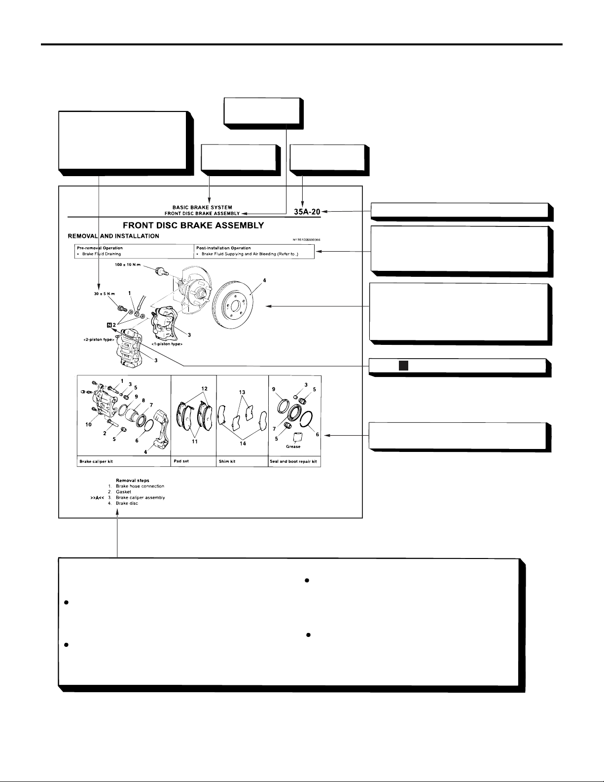
EXPLANATION OF MANUAL CONTENTS
Indicates the
Denotes tightening torque.
For bolts and nuts which do
not have a tightening torque
listed, refer to the "Standard
Parts tightening-torque Table"
section title.
Indicates the
group title.
00-3
Indicates the
group number.
Indicates the page number.
Indicates procedures to be performed before the work in that section is started, and
procedures to be performed after the work
in that section is finished.
Component diagram
A diagram of the component parts is provided near the front of each section in order
to give the reader a better understanding of
the installed condition of component parts.
Maintenance and servicing procedures
The numbers provided within the diagram indicate the
sequence for maintenance and servicing procedures.
Removal steps :
The part designation number corresponds to
the number in the illustration to indicate remov al steps.
Disassembly steps :
The part designation number corresponds to
the number in the illustration to indicate disas sembly steps.
Mark denotes nonreusable part.
N
Repair kit or parts sets are shown.
(Only very frequently used parts are shown.)
Installation steps :
Specified in case installation is impossible in
reverse order of removal steps. Omitted if
installation is possible in reverse order of re moval steps.
Reassembly steps :
Specified in case installation is impossible in
reverse order of removal steps. Omitted if
reassembly is possible in reverse order of dis assembly steps.
AC311238
AB
Page 6
00-4
GENERAL
HOW TO USE THIS MANUAL
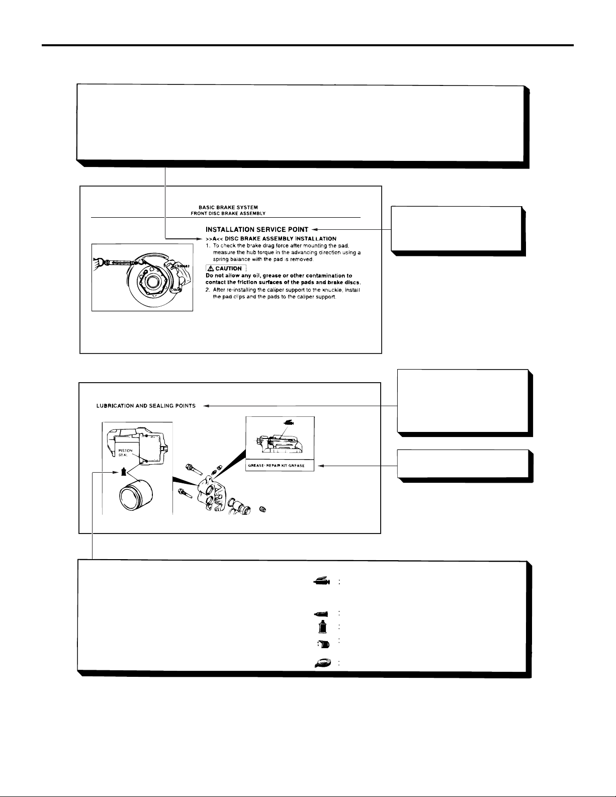
Classifications of major maintenance / service points
When there are major points relative to maintenance and servicing procedures (such as essential maintenance
and service points, maintenance and service standard values, information regarding the use of special tools, etc.).
These are arranged together as major maintenance and service points and explained in detail.
<<A>> : Indicates that there are essential points for removal or disassembly.
>>A<< : Indicates that there are essential points for installation or reassembly.
35A-21
Operating procedures,
cautions, etc. on removal,
installation, disassembly and
reassembly are described
The title of the page
(following the page on which
the diagram of component
parts is presented) indicating
the locations of lubrication and
sealing procedures.
Indicates (by symbols) where
lubrication is necessary.
Symbols for lubrication, sealants and adhesives
Symbols are used to show the locations for lubrication
and for application of sealants and adhesives.
These symbols are included in the diagram of component parts or on the page following the component
parts page. The symbols do not always have accompanying text to support that symbol.
Grease
(Multi-purpose grease unless there is a
brand or type specified)
Sealant or adhesive
Brake fluid or automatic transmission fluid
Engine oil, gear oil or air conditioning compressor oil
Adhesive tape or butyl rubber tape
AC311239
AB
Page 7

GENERAL
HOW TO USE TROUBLESHOOTING/INSPECTION SERVICE POINTS
00-5
HOW TO USE TROUBLESHOOTING/INSPECTION SERVICE
POINTS
CONTENTS OF TROUBLESHOOTING
M1001013300211
CAUTION
During diagnosis, a diagnosis code associated
with other system may be set when the ignition
switch is turned on with connector(s) discon
nected. On completion, confirm all systems for
diagnosis code(s). If diagnosis code(s) are set,
erase them all.
WARNING
Since the radiator fan rotates during CAN
bus line diagnostics, make sure that no one
is servicing the engine compartment before
diagnosing the CAN bus line. Since the CAN
communication stops when diagnosing the
CAN bus line, the ETACS-ECU detects the
time-out of the engine-ECU, and activates
the radiator fan to prevent overheating as
fail-safe.
Troubleshooting of electronic control systems for
which the M.U.T.-III can be used follows the basic
outline described below. Even in systems for which
the M.U.T.-III cannot be used, some of these sys
tems still follow this outline.
-
-
1. STANDARD FLOW OF DIAGNOSIS TROUBLESHOOTING
Troubleshooting sections are based on the diagnostic flow as below. If the diagnostic flow is different from
that given below, or if additional explanation is required, the details of such differences or additions will also
be listed.
Page 8

00-6
Diagnosis method
GENERAL
HOW TO USE TROUBLESHOOTING/INSPECTION SERVICE POINTS
Gathering information
from the customer.
Reoccurs
CAN bus diagnosis*
OK
Read the diagnosis code. Read the diagnosis code.
No diagnosis code
or communication
with M.U.T.-III not
possible
Refer to the INSPECTION CHART
FOR TROUBLE SYMPTOMS
(Refer to applicable group).
1
Diagnosis code
displayed.
(Past trouble)*
How to treat past
trouble*
3
4
Diagnosis code
displayed.
(Current trouble)*
Check trouble symptom.
NG
CAN bus diagnosis chart*
3
After taking note of the
malfunction code, erase the
diagnosis code memory.
Recheck trouble symptom.
Read the diagnosis codes.
Diagnosis code
displayed.
Refer to the INSPECTION CHART
FOR DIAGNOSIS CODES
(Refer to applicable group).
2
Diagnosis code
displayed.
(Current trouble)*
Does not reoccur
3
Diagnosis code
displayed.
(Past trouble)*
How to treat past
trouble*
4
No diagnosis
code.
INTERMITTENT MALFUNCTIONS*
3
No diagnosis
code.
5
AC501888
• *1: For how to diagnose CAN bus lines, refer to GROUP 54C .
• *2: For the CAN bus diagnosis chart, refer to GROUP 54C .
• *3: When the M.U.T.-III detects a diagnosis code, its display informs users whether a mechanical problem
currently exists or whether it existed before. The message for the former state identifies it as a "Active"
and the message for the latter identifies it as a "Stored".
• *4: For how to treat past trouble, refer to P.00-13.
• *5: For how to cope with intermittent malfunctions, refer to P.00-12.
2. SYSTEM OPERATION AND SYMPTOM VERIFICATION TESTS
If verification of the symptom(s) is difficult, procedures for checking operation and verifying symptoms
5. DIAGNOSIS CODE PROCEDURES
Indicates the inspection procedures corresponding to
each diagnosis code (Refer to How to Use Inspection
Procedures
P.00-8).
are shown.
6. TROUBLE SYMPTOM CHART
3. DIAGNOSIS FUNCTION
Details which are different from those in the "Diagnosis Function P.00-7" section are described.
If there are trouble symptoms even though the
M.U.T.-III does not find any diagnosis codes, Inspec
tion procedures for each trouble symptom will be
found by means of this chart.
4. DIAGNOSIS CODE CHART
Diagnostic trouble codes and diagnostic items are
shown.
-
Page 9
GENERAL
HOW TO USE TROUBLESHOOTING/INSPECTION SERVICE POINTS
00-7
7. SYMPTOM PROCEDURES
Indicates the inspection procedures corresponding to
each symptoms classified in the Symptom Chart
(Refer to How to Use Inspection Procedures
P.00-8).
8. SERVICE DATA REFERENCE TABLE
Inspection items and normal judgment values have
been provided in this chart as reference information.
9. ACTUATOR TEST TABLE
The Actuator Test item numbers, inspection items,
and judgment values have been provided in this
chart as reference information.
10. CHECK AT ECU TERMINALS
Terminal numbers for the ECU connectors, inspection items, and judgment values have been provided
in this chart as reference information.
11. INSPECTION PROCEDURE BY USING AN OSCILLOSCOPE
When there are inspection procedures using an
oscilloscope, these are described here.
DIAGNOSIS FUNCTION
M1001013400100
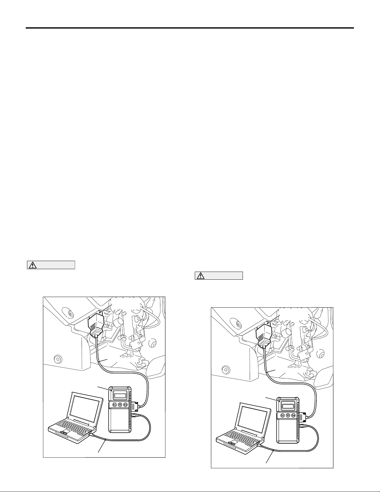
HOW TO READ DIAGNOSIS CODE
Connect the M.U.T.-III to the 16-pin diagnosis connector, and read the diagnosis code.
NOTE: For details on how to use the M.U.T.-III, refer
to the "M.U.T.-III operation manual."
1. Ensure that the ignition switch is at the "LOCK"
(OFF).
2. Start up the personal computer.
3. Connect M.U.T.-III USB cable MB991827 to
special tool Vehicle Communication Interface
(V.C.I.) MB991824 and the personal computer.
4. Connect M.U.T.-III main harness A MB991910 to
the V.C.I.
5. Connect the M.U.T.-III main harness A to the
diagnosis connector.
6. Turn the V.C.I. power switch to the "ON" position.
NOTE: When the V.C.I. is energized, the V.C.I.
indicator lamp will be illuminated in a green col
-
our.
7. Start the M.U.T.-III system on the personal
computer and turn the ignition switch to the "ON"
position.
8. Read the diagnosis code.
9. Disconnecting the M.U.T.-III is the reverse of the
connecting sequence, making sure that the
ignition switch is at the "LOCK" (OFF).
CAUTION
Before connecting or disconnecting the
M.U.T.-III, turn the ignition switch to the "LOCK"
(OFF) position.
Diagnosis
connector
MB991910
MB991824
ERASING DIAGNOSIS CODE
CAUTION
Before connecting or disconnecting the
M.U.T.-III, turn the ignition switch to the "LOCK"
(OFF) position.
Diagnosis
connector
MB991910
MB991824
MB991827
AC501413
AB
MB991827
AC501413
AB
Page 10
00-8
HOW TO USE TROUBLESHOOTING/INSPECTION SERVICE POINTS
GENERAL
Connect the M.U.T.-III to the diagnosis connector,
and erase the diagnosis code. The procedure is the
same as "How to Read Diagnosis Code
."
HOW TO USE THE INSPECTION PROCEDURES
M1001013500237
The causes of many of the problems occurring in electric circuitry are generally the connectors, components,
the ECU, the wiring harnesses between connectors, in that order. These inspection procedures follow this
order. They first try to discover a problem with a connector or a defective component.
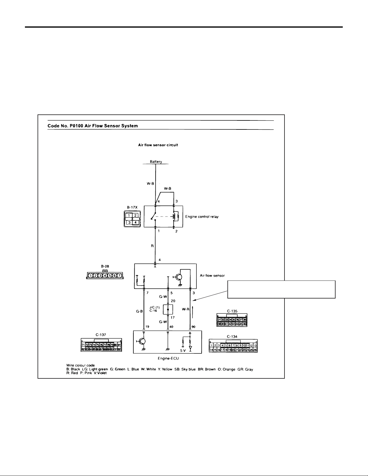
Relevant circuit(s) of the component which
the Code No. indicates are described.
AC301964
AB
Page 11
GENERAL
HOW TO USE TROUBLESHOOTING/INSPECTION SERVICE POINTS
00-9
Explains about the basic
operation of the components.
Explains about
technical details.
Describes the
conditions for that
diagnosis code being
set.
Start of diagnosis
procedure
Describes
inspection
procedure.
M.U.T.-III data list
Describes possible
causes(s) for that
diagnosis code.
CURRENT TROUBLE
Indicates that the status is "Active" and the trouble is
currently present. Carry out troubleshooting as
described in the applicable inspection procedure.
PAST TROUBLE
Indicates that the status is "Stored" and the trouble is
historic. Since the trouble may still be present, set
the vehicle to the diagnosis code detection condition
and check that the status changes to "Active". If the
status does not change from "Stored", observe the
applicable inspection procedure with particular
emphasis on connector(s) and wiring harness.
AC313955
AC
HARNESS CHECK
Check for an open or short circuit in the harness
between the terminals which are faulty according to
the connector measurements. Carry out this inspec
tion while referring to the Electrical Wiring Manual.
Here, "Check the wiring harness between the power
supply and terminal xx" also includes checking for
blown fuse. For inspection service points when there
is a blown fuse, refer to "Inspection Service Points
for a Blown Fuse
P.00-12."
MEASURES TO TAKE AFTER REPLACING THE ECU
If the trouble symptoms have not disappeared even
after replacing the ECU, repeat the inspection proce
dure from the beginning.
-
Page 12
00-10
GENERAL
HOW TO USE TROUBLESHOOTING/INSPECTION SERVICE POINTS
CONNECTOR MEASUREMENT SERVICE POINTS
M1001013600223
CAUTION
During diagnosis, a diagnosis code associated
with other system may be set when the ignition
switch is turned on with connector(s) discon
nected. On completion, confirm all systems for
diagnosis code(s). If diagnosis code(s) are set,
erase them all.
Turn the ignition switch to the "LOCK" (OFF) position
when connecting and disconnecting the connectors.
Turn the ignition switch to "ON" when measuring,
unless there are instructions to the contrary.
IF INSPECTING WITH THE CONNECTOR
CONNECTED <WATERPROOF
CONNECTORS>
CAUTION
Never insert a test probe from the harness side,
as this will reduce the waterproof performance
and result in corrosion.
Inspect by inserting a test probe from the harness
side. If the connector is too small to insert a test
probe (e.g. control unit connector), do not insert it
forcibly. Use special tool extra fine probe
(MB992006).
IF INSPECTING WITH THE CONNECTOR
DISCONNECTED <WHEN INSPECTING A
FEMALE PIN>
CAUTION
• Use special tool check harness (MB991219). If
the test bar is inserted forcibly, it will cause a
poor contact.
•
If the connector is disconnected, a diagnosis
code may be stored for the system to be
checked or other systems.
MB991219
Special tool
AC105597
AB
Use the special tools such as test harness, harness
connector or check harness.
IF INSPECTING WITH THE CONNECTOR
CONNECTED <ORDINARY
(NON-WATERPROOF) CONNECTORS>
MB992006
AC105598
AH
AC105599
AB
Use check harness (MB991219) of special tool harness set (MB991223).
IF INSPECTING WITH THE CONNECTOR
DISCONNECTED <WHEN INSPECTING A
MALE PIN>
CAUTION
• Be careful not to short the connector pins
with the test bars. To do so may damage the
circuits inside the ECU.
•
If the connector is disconnected, a diagnosis
code may be stored for the system to be
checked or other systems.
AC105600
Touch the pin directly with the test bar.
Page 13
GENERAL
HOW TO USE TROUBLESHOOTING/INSPECTION SERVICE POINTS
00-11
CONNECTOR INSPECTION SERVICE POINTS
M1001013700189
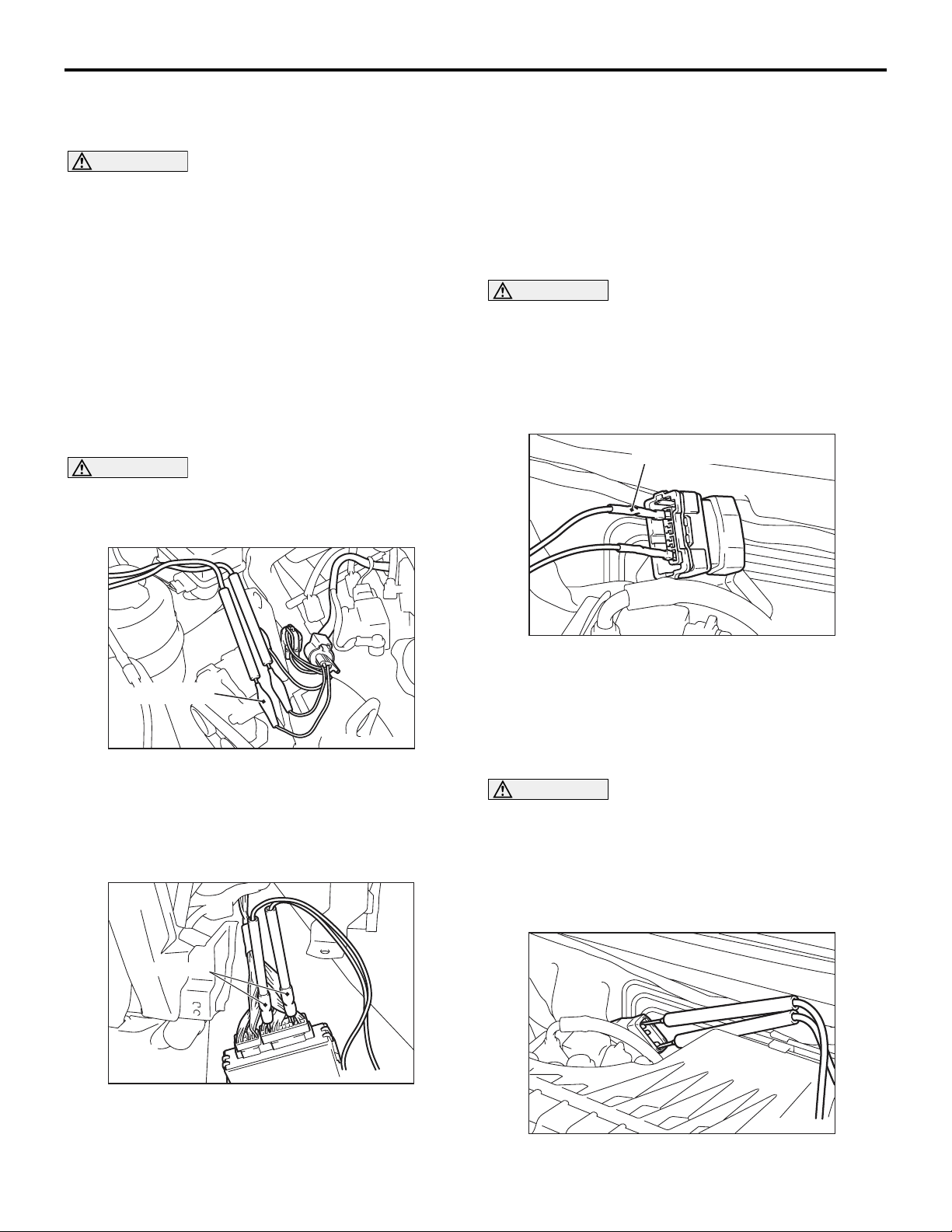
VISUAL INSPECTION
•
Connector disconnected or
improperly connected
Stretched or broken wires
• Low contact pressure between male and female
terminals
• Low connection pressure due to rusted terminals
or foreign matter lodged in terminals
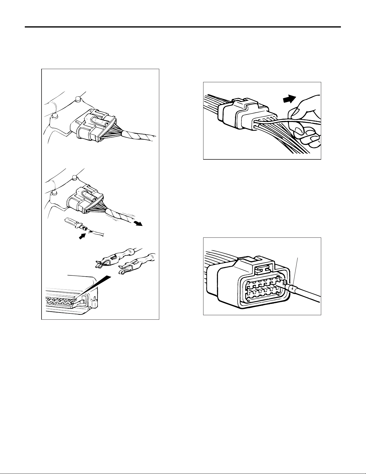
CONNECTOR PIN INSPECTION
AC300898
If the connector pin stopper is damaged, the terminal
connections (male and female pins) will not be per
fect even if the connector body is connected, and the
pins may pull out of the reverse side of the connec
tor. Therefore, gently pull the harnesses one by one
to make sure that no pins pull out of the connector.
-
-
Harness wire breakage
at terminal section
Low contact
pressure
Good
Bad
AC300896
AB
Connector is disconnected or improperly connected
• Connector pins are pulled out
• Due to harness tension at terminal section
CONNECTOR ENGAGEMENT
INSPECTION
MB991219
AC300899
Use special tool inspection harness (MB991219)
(connector pin connection pressure inspection har
ness of the inspection harness set) to inspect the
engagement of the male pins and female pins. (Pin
drawing force: 1 N or more)
AB
-
Page 14
00-12
GENERAL
HOW TO USE TROUBLESHOOTING/INSPECTION SERVICE POINTS
INSPECTION SERVICE POINTS FOR A BLOWN FUSE
M1001013800186
CAUTION
A diagnosis code may be stored due to a blown
fuse.
Battery
Fuse
Short-circuit
Load
switch
occurrence
section
HOW TO COPE WITH INTERMITTENT MALFUNCTIONS
M1001013900183
Load
AC300900
AB
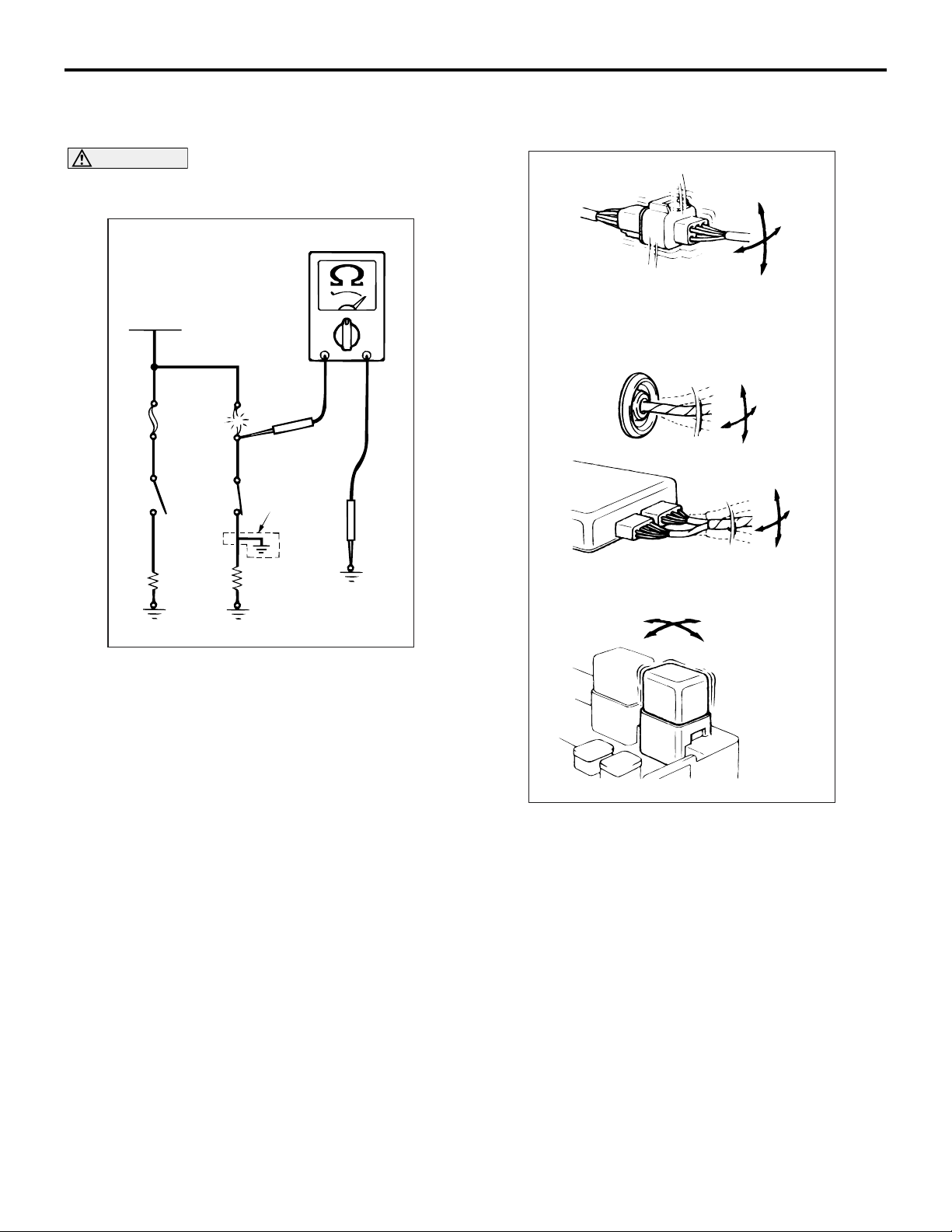
Remove the blown fuse and measure the resistance
between the load side of the blown fuse and the
earth. Close the switches of all circuits which are
connected to this fuse. If the resistance is almost 0
Ω
at this time, there is a short somewhere between
these switches and the load. If the resistance is not 0
Ω, there is no short at the present time, but a momentary short has probably caused the fuse to blow.
The main causes of a short circuit are the following.
• Harness being clamped by the vehicle body
• Damage to the outer casing of the harness due to
wear or heat
• Water getting into the connector or circuitry
• Human error (mistakenly shorting a circuit, etc.)
AC300901
Intermittent malfunctions often occur under certain
conditions, and if these conditions can be ascer
tained, determining the cause becomes simple. In
order to ascertain the conditions under which an
intermittent malfunction occurs, first ask the cus
tomer for details about the driving conditions,
weather conditions, frequency of occurrence and
trouble symptoms, and then try to recreate the trou
ble symptoms. Next, ascertain whether the reason
why the trouble symptom occurred under these con
ditions is due to vibration, temperature or some other
factor. If vibration is thought to be the cause, carry
out the following checks with the connectors and
components to confirm whether the trouble symptom
occurs. The objects to be checked are connectors
and components which are indicated by inspection
procedures or given as probable causes (which gen
erates diagnosis codes or trouble symptoms).
-
-
Page 15
GENERAL
VEHICLE IDENTIFICATION
00-13
• Gently shake the connector up, down and to the
left and right.
• Gently shake the wiring harness up, down and to
the left and right.
• Gently rock each sensor and relay, etc. by hand.
• Gently shake the wiring harness at suspensions
and other moving parts.
NOTE: If determining the cause is difficult, the drive
recorder function of the M.U.T.-III can also be used.
(For details on how to use the M.U.T.-III, refer to the
"M.U.T.-III operation manual).
VEHICLE IDENTIFICATION
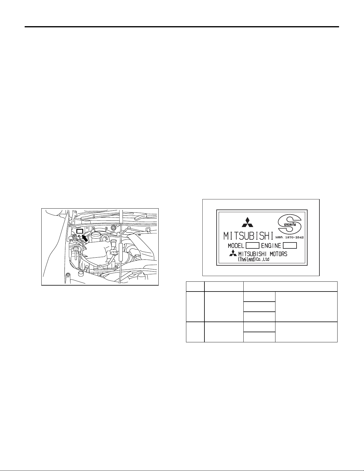
VEHICLE NAME PLATE
HOW TO TREAT PAST TROUBLE
M1001014100157
Since the trouble may still be present even the status
is "Stored", set the vehicle to the diagnosis code
detection condition and check that the status
changes to "Active". If the status does not change
from "Stored", carry out the following procedure.
1. Establish from the customer whether a fuse or
connector has been replaced or disconnected.
2. If yes, erase the diagnosis code, and then check
that no diagnostic code is reset. If no diagnosis
code is reset, the diagnosis is complete.
3. If no, follow the applicable Diagnostic Trouble
Code Chart. Then check the wiring harness and
connector, and refer to "How to Cope with
Intermittent Malfunction
P.00-12 ."
M1001000401255
AC501406
AB
The name plate is riveted to the cowl top outer panel
in the engine compartment.
12
AC501266
AB
No. Item Content
1 MODEL KA4 Vehicle model
KB4
KB8
2 ENGINE 4D56 Engine model
4M41
Page 16

00-14
VEHICLE IDENTIFICATION
GENERAL
MODELS
<CLUB CAB>
Model code Engine model Transmission model Fuel supply system
KA4T NCNMFRU 4D56 IDI (Indirect
Diesel Injection) SOHC
engine with Turbo
charger (2,477 mL)
NCNUZRU 4D56 DI-D (Direct
Injection-Diesel) DOHC
engine with Turbo
NCRUZRU R4AW4
charger (2,477 mL)
2WD
(rear axle
drive)
R5M21
(5-speed manual
transmission)
R5MB1
(5-speed manual
transmission)
(4-speed automatic
transmission)
Electrical fuel injection
(distribution type
injection pump system)
Electrical fuel injection
(common rail engine
control system)
KB4T GCNHZRU 4D56 DI-D (Direct
Injection-Diesel) DOHC
engine with Inter cooler,
Turbo charger (2,477
mL)
KB8T GCNHZRU 4M41 DI-D (Direct
Injection-Diesel) engine
with Inter cooler, Turbo
charger (3,200 mL)
<DOUBLE CAB>
Model code Engine model Transmission model Fuel supply system
KA4T NJNMZRU 4D56 DI-D (Direct
Injection-Diesel) DOHC
engine with Turbo
NJNUZRU
NJRUZRU R4AW4
charger (2,477 mL)
4WD
(easy select
4WD)
2WD
(rear axle
drive)
V5MB1
(5-speed manual
transmission)
R5MB1
(5-speed manual
transmission)
(4-speed automatic
transmission)
Electrical fuel injection
(common rail engine
control system)
KB4T GJNHZRU 4D56 DI-D (Direct
Injection-Diesel) DOHC
engine with Inter cooler,
Turbo charger (2,477
mL)
KB8T GJNHZRU 4M41 DI-D (Direct
Injection-Diesel) engine
with Inter cooler, Turbo
GJNXZRU
GJRXZRU V4A5A
charger (3,200 mL)
4WD
(easy select
4WD)
V5MB1
(5-speed manual
transmission)
(4-speed automatic
transmission)
Page 17

GENERAL
VEHICLE IDENTIFICATION
MODEL CODE
1 2 3 4 5 6 7 8 9 10 11
No. Item Content
1 Development K TRITON
2 Drive system A 2WD
B 4WD
3 Engine type 4 2,477 mL
8 3,200 mL
4 Sort T Truck
5 Vehicle width N Standard
G Wide fender
6 Body style C Club cab
00-15
AC407365
AB
J Double cab
7 Transmission type N 5-speed manual transmission
R 4-speed automatic transmission
8 Vehicle grade M GL
U GLX
H GLS
X GLS-S
9 Specification engine feature F Turbo charger
9 Specification engine feature Z Inter cooler, turbo charger
10 Steering wheel location R Right hand
11 Destination U For Thailand
Page 18
00-16
GENERAL
VEHICLE IDENTIFICATION
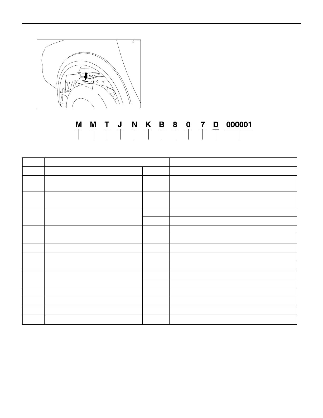
CHASSIS NUMBER
The chassis number is stamped on the side wall of
the frame near the rear wheel (RH).
Frame
AC501503
AB
1234567891011 12
No. Item Content
1 Country of manufacture M Asia
2 Maker
(distribution channel)
M MMC Sittipol Co., Ltd.
(Thailand)
AC501425
AB
3 Destination and steering wheel
T For Thailand, right hand
location
4 Body style C Club cab
J Double cab
5 Transmission type N 5-speed manual transmission
R 4-speed automatic transmission
6 Vehicle line K MITSUBISHI TRITON
7 Development order A 2-wheel drive
B 4-wheel drive
8 Engine type 4 2,477mL diesel engine
8 3,200mL diesel engine
9 MSC internal purpose 0 No meaning
10 Model year 7 2006
11 Plant D MMC Sittipol Co., Ltd.
12 Serial number
− −
Page 19
GENERAL
GENERAL DATA AND SPECIFICATIONS
00-17
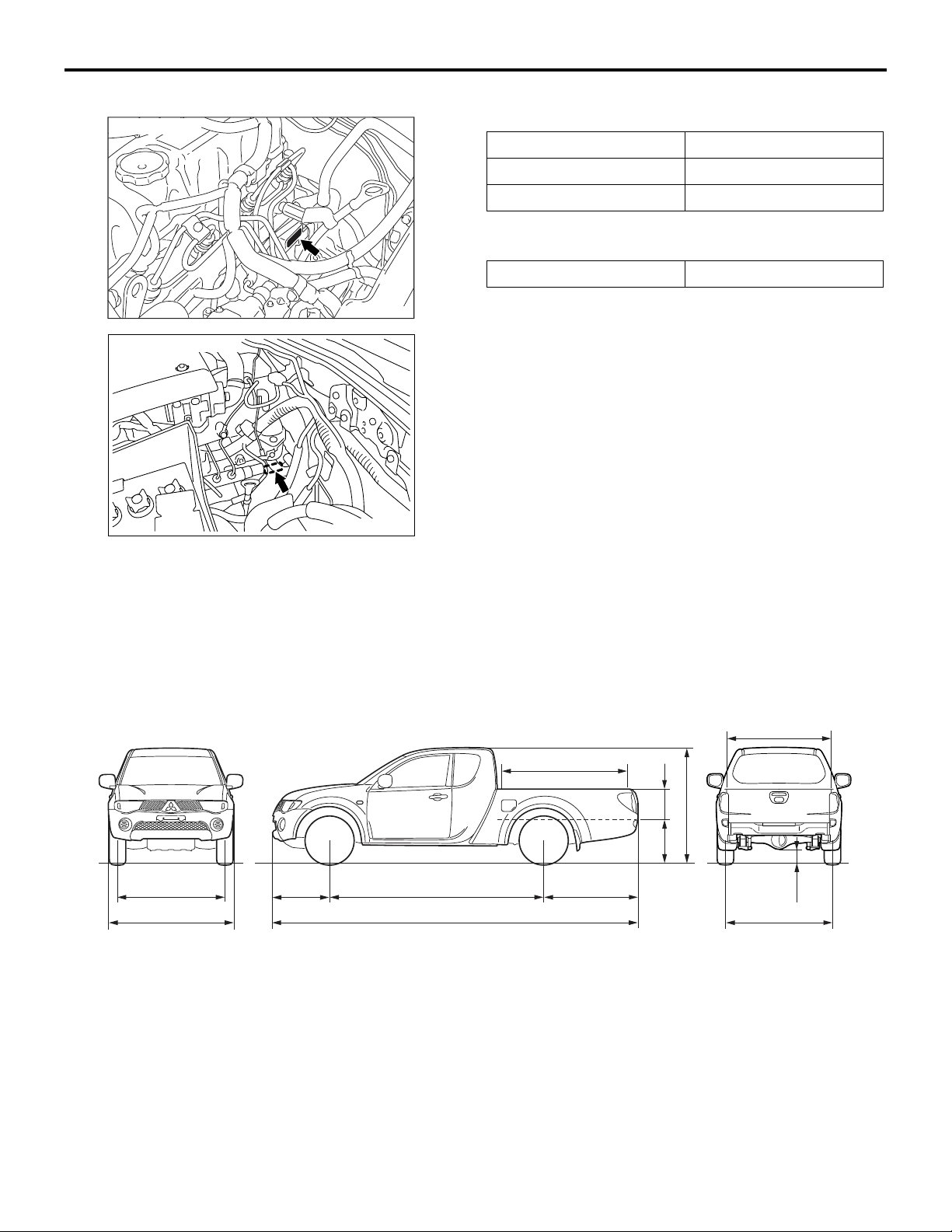
ENGINE MODEL STAMPING
<4D5-SOHC>
<4D5-DOHC, 4M4>
AC502319
AC502538
The engine model is stamped on the cylinder block.
This engine model numbers is as shown as follow.
Engine model Engine displacement
4D56 2,477 mL
4M41 3,200 mL
The engine serial number is stamped near the
engine model number.
Engine serial number AA0201 to YY9999
AB
AB
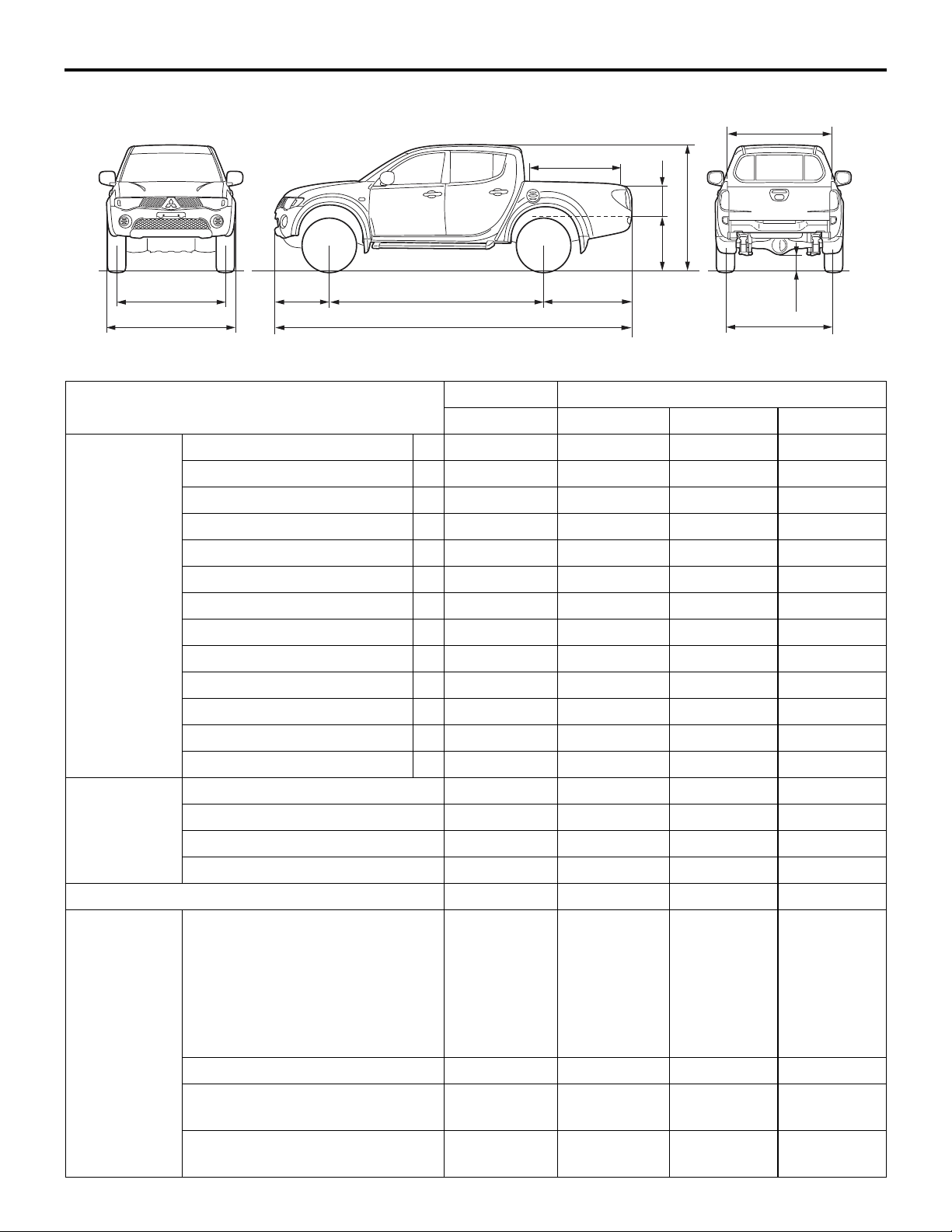
CLUB CAB
<2WD>
GENERAL DATA AND SPECIFICATIONS
10
1
3
2
4
5
6
12
8
13
M1001000900945
11
7
9
AC502183
AB
Page 20

00-18
Items KA4T
GENERAL DATA AND SPECIFICATIONS
GENERAL
NCNMFRU NCNUZRU NCRUZRU
Vehicle
dimensions
mm
Vehicle weight kgKerb weight 1,565 1,600 1,600
Seating capacity 2 2 2
Front track 1 1,505 1,505 1,505
Overall width 2 1,750 1,750 1,750
Front overhang 3 785 785 785
Wheel base 4 3,000 3,000 3,000
Rear overhang 5 1,325 1,325 1,325
Overall length 6 5,110 5,110 5,110
Ground clearance (unladen) 7 200 195 195
Overall height (unladen) 8 1,660 1,655 1,655
Rear track 9 1,500 1,500 1,500
BED interior length 10 1,805 1,805 1,805
BED interior width 11 1,470 1,470 1,470
BED interior height 12 405 405 405
Cargo floor height (unladen) 13 725 720 720
Max. gross vehicle weight 2,285 2,330 2,330
Max. axle weight rating-front 1,030 1,030 1,030
Max. axle weight rating-rear 1,500 1,500 1,500
Engine Model No. 4D56 IDI (Indirect
Diesel Injection)
engine with
Turbo charger
Total displacement mL 2,477 2,477 2,477
Max. output kW (SP)/rpm 66 (90)/4,000 81 (110)/4,000 81 (110)/4,000
Max. torque N⋅ m/rpm 196 (20)/2,000 240 (24.5)/2,000 240 (24.5)/2,000
Transmission Model No. R5M21 R5MB1 R4AW4
Type 5-speed manual 5-speed manual 4-speed
Fuel system Fuel supply system Electrical fuel
injection
(distribution type
injection pump
system)
Max speed km/h 150 160 158
Turning radius m 5.7 5.7 5.7
4D56 DI-D
(Direct
Injection-Diesel)
engine with
Turbo charger
Electrical fuel
injection
(common rail
engine control
system)
4D56 DI-D (Direct
Injection-Diesel)
engine with Turbo
charger
automatic
Electrical fuel
injection
(common rail
engine control
system)
Page 21

<4WD>
GENERAL
GENERAL DATA AND SPECIFICATIONS
00-19
11
10
1
2
3
4
6
5
12
8
13
Items KB4T KB8T
GCNHZRU GCNHZRU
Vehicle
dimensions
mm
Front track 1 1,520 1,520
Overall width 2 1,800 1,800
Front overhang 3 785 785
Wheel base 4 3,000 3,000
Rear overhang 5 1,325 1,325
Overall length 6 5,110 5,110
Ground clearance (unladen) 7 205 205
7
9
AC502184
AB
Overall height (unladen) 8 1,780 1,780
Rear track 9 1,515 1,515
BED interior length 10 1,805 1,805
BED interior width 11 1,470 1,470
BED interior height 12 405 405
Cargo floor height (unladen) 13 860 860
Vehicle weight kgKerb weight 1,795 1,840
Max. gross vehicle weight 2,535 2,605
Max. axle weight rating-front 1,250 1,250
Max. axle weight rating-rear 1,600 1,600
Seating capacity 2 2
Engine Model No. 4D56 DI-D (Direct
Injection-Diesel) engine
with Inter cooler, Turbo
charger
4M41 DI-D (Direct
Injection-Diesel) engine
with Inter cooler, Turbo
charger
Total displacement mL 2,477 3,200
Max. output kW (PS)/rpm 100 (136)/4,000 118 (136)/3,800
Max. torque N⋅ m/rpm 314 (32)/2,000 343 (35)/2,000
Transmission Model No. V5MB1
Type 5-speed manual
Page 22
00-20
GENERAL DATA AND SPECIFICATIONS
GENERAL
Items KB4T KB8T
GCNHZRU GCNHZRU
Fuel system Fuel supply system Electrical fuel injection
(common rail engine
control system)
Electrical fuel injection
(common rail engine
control system)
Max speed km/h 175 175
Turning radius m 5.9 5.9
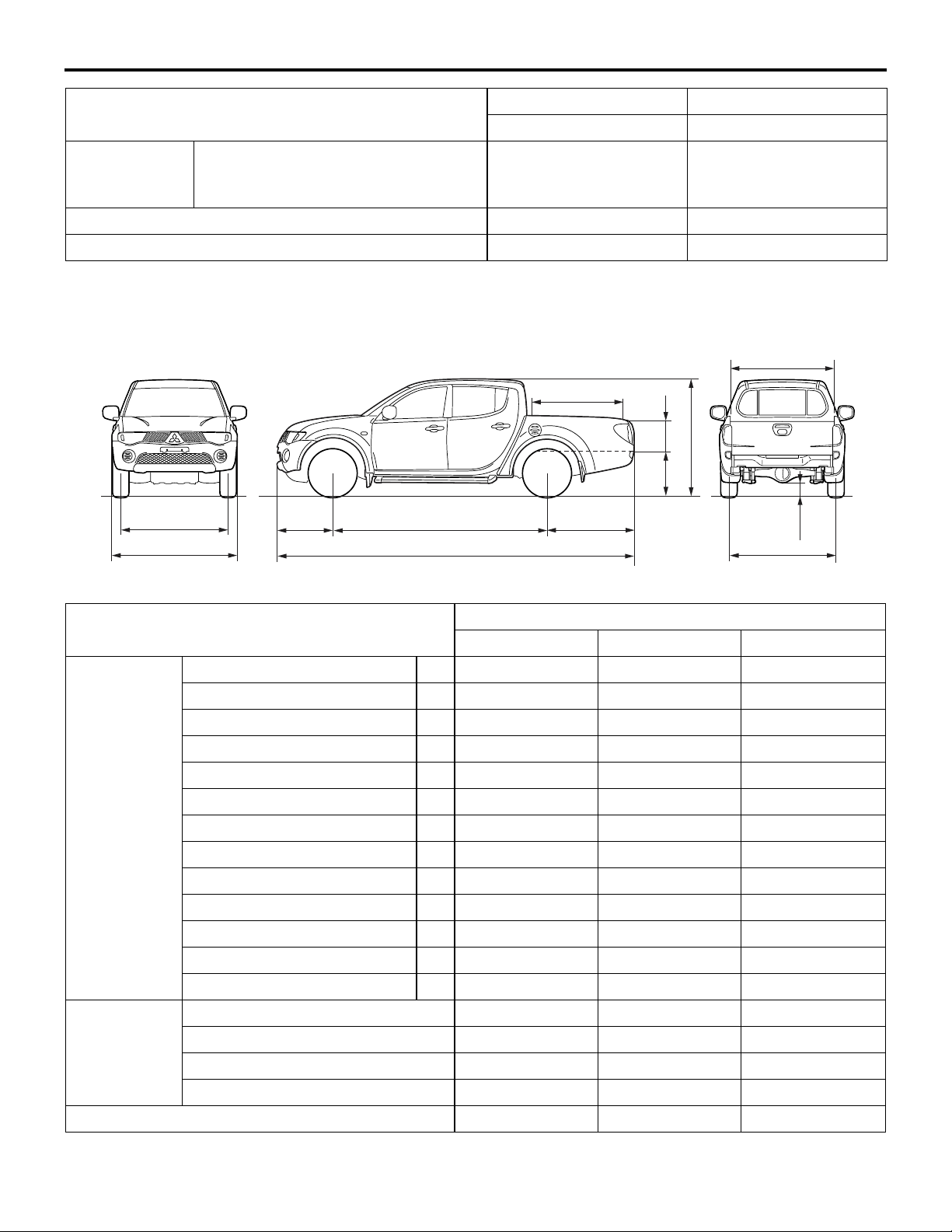
DOUBLE CAB
<2WD>
10
1
2
3
4
6
5
12
8
13
11
9
7
AC502185
AB
Items KA4T
NJNMZRU NJNUZRU NJRUZRU
Vehicle
dimensions
Front track 1 1,505 1,505 1,505
Overall width 2 1,750 1,750 1,750
mm
Front overhang 3 785 785 785
Wheel base 4 3,000 3,000 3,000
Rear overhang 5 1,210 1,210 1,210
Overall length 6 4,995 4,995 4,995
Ground clearance (unladen) 7 200 195 195
Overall height (unladen) 8 1,655 1,650 1,650
Rear track 9 1,500 1,500 1,500
BED interior length 10 1,325 1,325 1,325
BED interior width 11 1,470 1,470 1,470
BED interior height 12 405 405 405
Cargo floor height (unladen) 13 715 710 710
Vehicle
weight kg
Kerb weight 1,640 1,640 1,640
Max. gross vehicle weight 2,330 2,330 2,330
Max. axle weight rating-front 1,030 1,030 1,030
Max. axle weight rating-rear 1,500 1,500 1,500
Seating capacity 5 5 5
Page 23

GENERAL
GENERAL DATA AND SPECIFICATIONS
Items KA4T
NJNMZRU NJNUZRU NJRUZRU
00-21
Engine Model No. 4D56 DI-D
(Direct
Injection-Diesel)
engine with
Turbo charger
Total displacement mL 2,477 2,477 2,477
Max. output kW (PS)/rpm 81 (110)/4,000 81 (110)/4,000 81 (110)/4,000
Max. torque N⋅ m/rpm 240 (24.5)/2,000 240 (24.5)/2,000 240 (24.5)/2,000
Transmission Model No. R5MB1 R5MB1 R4AW4
Type 5-speed manual 5-speed manual 4-speed
Fuel system Fuel supply system Electrical fuel
injection
(common rail
engine control
system)
Max speed km/h 160 160 158
Turning radius m 5.7 5.7 5.7
4D56 DI-D
(Direct
Injection-Diesel)
engine with
Turbo charger
Electrical fuel
injection
(common rail
engine control
system)
4D56 DI-D (Direct
Injection-Diesel)
engine with Turbo
charger
automatic
Electrical fuel
injection
(common rail
engine control
system)
Page 24
00-22
<4WD>
GENERAL
GENERAL DATA AND SPECIFICATIONS
11
10
1
2
3
4
6
5
Items KB4T KB8T
GJNHZRU GJNHZRU GJNXZRU GJRXZRU
Vehicle
dimensions
Front track 1 1,520 1,520 1,520 1,520
Overall width 2 1,800 1,800 1,800 1,800
mm
Front overhang 3 785 785 785 785
Wheel base 4 3,000 3,000 3,000 3,000
Rear overhang 5 1,210 1,210 1,210 1,210
Overall length 6 4,995 4,995 4,995 4,995
Ground clearance (unladen) 7 205 205 205 205
Overall height (unladen) 8 1,780 1,780 1,780 1,780
12
13
8
7
9
AC502186
AB
Rear track 9 1,515 1,515 1,515 1,515
BED interior length 10 1,325 1,325 1,325 1,325
BED interior width 11 1,470 1,470 1,470 1,470
BED interior height 12 405 405 405 405
Cargo floor height (unladen) 13 850 850 850 850
Vehicle
weight kg
Kerb weight 1,860 1,920 1,930 1,940
Max. gross vehicle weight 2,535 2,605 2,605 2,605
Max. axle weight rating-front 1,250 1,250 1,250 1,250
Max. axle weight rating-rear 1,600 1,600 1,600 1,600
Seating capacity 5 5 5 5
Engine Model No. 4D56 DI-D
(Direct
Injection-Dies
el) engine
with Inter
cooler, Turbo
charger
4M41 DI-D
(Direct
Injection-Die
sel) engine
with Inter
cooler, Turbo
charger
4M41 DI-D
(Direct
Injection-Die
sel) engine
with Inter
cooler, Turbo
charger
Total displacement mL 2,477 3,200 3,200 3,200
Max. output kW (PS)/rpm 100
(136)/4,000
Max. torque N⋅ m/rpm 314
(32)/2,000
118
(160)/3,800
343
(35)/2,000
118
(160)/3,800
343
(35)/2,000
4M41 DI-D
(Direct
Injection-Die
sel) engine
with Inter
cooler, Turbo
charger
118
(160)/3,800
343
(35)/2,000
Page 25

GENERAL
PRECAUTIONS BEFORE SERVICE
Items KB4T KB8T
GJNHZRU GJNHZRU GJNXZRU GJRXZRU
Transmission Model No. V5MB1 V5MB1 V5MB1 V4A5A
Type 5-speed
manual
Fuel system Fuel supply system Electrical fuel
injection
(common rail
engine
control
system)
Max speed km/h 175 175 175 175
Turning radius m 5.9 5.9 5.9 5.9
5-speed
manual
Electrical fuel
injection
(common rail
engine
control
system)
5-speed
manual
Electrical
fuel injection
(common rail
engine
control
system)
00-23
4-speed
automatic
Electrical
fuel injection
(common rail
engine
control
system)
PRECAUTIONS BEFORE SERVICE
SUPPLEMENTAL RESTRAINT SYSTEM (SRS) AND SEAT BELT WITH PRE-TENSIONER
M1001011600238
CAUTION
Items to review when servicing SRS:
1. Be sure to read GROUP 52B − Supplemental
Restraint System (SRS). For safe operation,
please follow the directions and heed all
warnings.
2. Wait at least 60 seconds after disconnecting
the battery cable before doing any further
work. The SRS system is designed to retain
enough voltage to deploy the air bag even
after the battery has been disconnected. Seri
ous injury may result from unintended air bag
deployment if work is done on the SRS sys
tem immediately after the battery cable is disconnected.
3. Warning labels must be heeded when servic-
ing or handling SRS components. Warning
labels can be found in the following locations.
• SRS air bag control unit (SRS-ECU)
• Front impact sensor
• Clock spring
• Driver's and front passenger's air bag
modules
• Seat belt with pre-tensioner
4. Always use the designated special tools and
test equipment.
5. Store components removed from the SRS in a
clean and dry place. The air bag module
should be stored on a flat surface and placed
-
so that the pad surface is facing upward. Do
not place anything on top of it.
6. Never attempt to disassemble or repair the
SRS components (SRS-ECU, air bag module
and clock spring).
7. Whenever you finish servicing the SRS, check
the SRS warning lamp operation to make sure
that the system functions properly.
8. Be sure to deploy the air bag before dispos-
ing of the air bag module or disposing of a
vehicle equipped with an air bag (Refer to
GROUP 52B
dures).
Observe the following when carrying out operations on places where SRS components are
installed, including operations not directly
related to the SRS air bag.
1. When removing or installing parts, do not
allow any impact or shock to the SRS compo
nents.
2. If heat damage may occur during paint work,
remove the SRS-ECU, the air bag module,
clock spring, the front impact sensor, and the
seat belt pre-tensioner.
• SRS-ECU, air bag module, clock spring,
front impact sensor: 93
• Seat belt pre-tensioner: 90 ° C or more
− Air Bag Module Disposal Proce-
° C or more
-
Page 26
00-24
PRECAUTIONS BEFORE SERVICE
GENERAL
WHAT THE COMMON RAIL ENGINE LEARNS
After fuel-related parts are replaced, the common rail
engine must register their identification codes with
the engine-ECU and execute learning.
The table below shows what should be registered
and learned after each type of operation.
Correspondence table
Registration and
learning item
Injector identification
code registration
Small injection quantity
learning
Supply pump correction
learning
Operation type
Injector replacement Supply pump
replacement
appricable
appricable
−
−
−
appricable
M1001012500018
NOTE: When the engine-ECU is replaced, collect in
advance the injector identification code from the cur
rent engine-ECU. Doing it makes registration easy.
Engine-ECU
replacement
appricable
appricable
−
-
REGISTRATION AND LEARNING PROCEDURE
Injector identification code registration
Refer to P.00-24, INJECTOR IDENTIFICATION
CODE REGISTRATION PROCEDURE.
Small injection quantity learning
Refer to P.00-25, SMALL INJECTION QUANTITY
LEARNING PROCEDURE.
Supply pump correction learning
Refer to P.00-26, SUPPLY PUMP CORRECTION
LEARNING PROCEDURE.
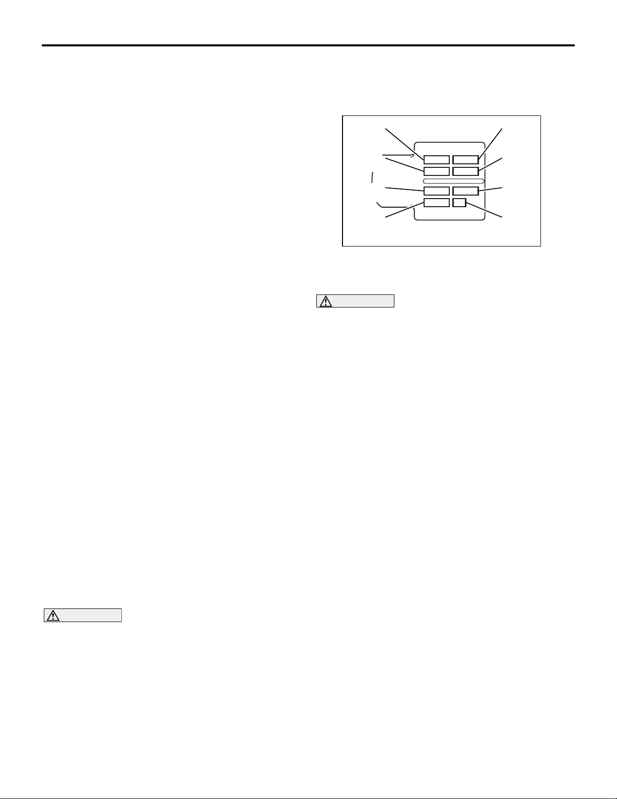
INJECTOR IDENTIFICATION CODE REGISTRATION PROCEDURE
CAUTION
1. If the injector identification code is not regis-
tered, the engine warning lamp goes on and
diagnosis code No. P1626 is logged.
2. Failure to register the injector identification
code correctly will cause rough idling, abnor
mal noise, and emission deterioration.
PURPOSE
Identification code
-
Because individual injectors have different injection
characteristics, the engine-ECU corrects injection
time for each cylinder to improve injection accuracy.
For this reason, when the injector or engine-ECU is
replaced, injector correction data must be registered
afterwards in the engine-ECU using the Multi Use
Tester III (M.U.T.-III).
Correction data is converted into an identification
code consisting of 30 alphanumeric characters and
printed on the injector connector.
AK501491
M1001012600015
AB
Page 27
GENERAL
PRECAUTIONS BEFORE SERVICE
00-25
REGISTRATION PROCEDURE
1. When replacing the engine-ECU, connect the
current engine-ECU to the body harness.
NOTE: This operation is purposed to read the injector identification code stored in the engine-ECU.
Reading the identification code in this way before
replacement can eliminate manual input of the identi
fication code after replacement.
2. After the ignition switch is in "LOCK" (OFF)
position, connect the M.U.T.-III to the diagnosis
connector.
3. Turn the ignition switch to "ON" position.
4. Select SPECIAL FUNCTION from the function
menu.
5. When the current engine-ECU is still mounted,
read and register the injector identification code
as follows:
(1) Select Read Injector ID Code (for engine-ECU
replacement) from the SPECIAL FUNCTION
menu.
(2) Select Write and Save Injector ID Code from
the menu to read data from the current
engine-ECU and save the data if it could be
read normally.
(3) Mount the new engine-ECU on the vehicle.
(4) Select SPECIAL FUNCTION from the function
menu.
(5) Select Write Injector ID Code (for engine-ECU
replacement) from the SPECIAL FUNCTION
menu.
(6) Select SAVED INJECTOR ID WRITING from
the Write Injector ID Code menu to write the
data, which was saved previously, to the
engine-ECU.
6. If the injector has been replaced or data has not
been read from the current engine-ECU, register
the injector identification code as follows:
(1) Select Write Injector ID Code from the
SPECIAL FUNCTION menu.
(2) If the injector was replaced, specify whether to
write to every cylinder or a specific cylinder.
Frame 1
(4 digits)
Frame 2
(4 digits)
-
Frame 3
(4 digits)
Frame 5
(4 digits)
Frame 7
(4 digits)
Frame 4
(4 digits)
Frame 6
(4 digits)
Frame 8
(2 digits)
AK501492
AB
(3) Select the write mode from the menu, enter
the identification code printed on the injector,
and execute writing.
CAUTION
Even if the number of the cylinder to be registered does not match the actual injector mounting location, registration ends normally. Specify
the cylinder number correctly.
NOTE: The identification code is displayed in order
of the frame numbers when it is read.
7. Makes sure that the engine warning lamp that is
on changes to blinking, indicating the registration
is complete.
NOTE: When the injector is replaced, executing the
write operation also clears the values of small injec
tion quantity learning.
8. Execute small injection quantity learning.
Refer to P.00-25, the SMALL INJECTION
QUANTITY LEARNING PROCEDURE for the
learning procedure.
9. Confirm that the engine warning lamp is off.
Confirm also that the diagnosis code is not stored.
-
SMALL INJECTION QUANTITY LEARNING PROCEDURE
CAUTION
1. If small injection quantity learning has not
been executed, the engine warning lamp
blinks.
2. When the requirements for learning are satis-
fied by operation after replacement of the
engine-ECU, learning is automatically exe
cuted even if no instruction is given from the
M.U.T.-III. Accordingly, the malfunction indica
tor lamp goes off. However, the learning thus
executed is tentative and limited. Be sure to
complete leaning using the M.U.T.-III.
PURPOSE
To keep emission and noise level at adequate levels,
the engine-ECU must learn injector fuel injection in
idle mode.
During learning, the engine-ECU calculates actual
injection from each cylinder based on changes in
engine speeds and corrects pilot injection control. It
then keeps records of this amount of correction as a
learned value.
-
For this reason, after the engine-ECU or injector is
replaced, learning must be executed using the
M.U.T.-III.
M1001014300010
Page 28

00-26
GENERAL
PRECAUTIONS BEFORE SERVICE
NOTE: Engine friction changes or injector deterioration over time may cause fluctuation in pilot injection.
After use over time, it may prevent injection of an
accurate amount of fuel according to the indication
by the engine-ECU. This is why learning must be
executed again periodically.
For this reason, the engine-ECU periodically leans
injection according to the cumulative mileage.
Note that making the M.U.T.-III learn again resets the
cumulative mileage.
NOTE: The engine sound may change or idling
engine speeds may increase during injection learn
ing. These are not abnormalities.
-
LEARNING PROCEDURE
1. After the ignition switch is in "LOCK" (OFF)
position, connect the M.U.T.-III to the diagnosis
connector.
2. Put the vehicle in the following idling stable
conditions:
• Engine coolant temperature: 80 − 90°C
• Automatic transmission fluid temperature: 60° C
or higher
• Lamps, A/C condenser fan and all accessories:
OFF
• Transmission: Neutral <M/T>, "P" range <A/T>
• Power steering: Static state
3. Select SPECIAL FUNCTION from the function
menu.
4. Select SMALL INJECTION QUANTITY
LEARNING from the SPECIAL FUNCTION menu
to execute learning.
CAUTION
If the vehicle conditions go out of the learning
conditions during idling, learning is interrupted.
To reexecute learning, the ignition switch
must once be turned off.
5. Continue idling for about 3 minutes before
learning is completed.
6. Confirm that the engine warning lamp is off. If it
still blinks, reexecute learning.
SUPPLY PUMP CORRECTION LEARNING PROCEDURE
PURPOSE
The engine-ECU learns the relation between the
suction control valve (linear solenoid valve) of the
supply pump drive current and the fuel injection vol
ume.
The learning value is calculated from the suction
control valve drive current and the rail pressure sen
sor output voltage.
When the supply pump is replaced, therefore, this
learning must be executed.
Re-learning is executed when the engine is idling
after the learning value in the engine-ECU has been
reset by the M.U.T.-III.
M1001014400017
-
Page 29
GENERAL
PRECAUTIONS BEFORE SERVICE
LEARNING PROCEDURE FOR IDLING
After the ignition switch is in "LOCK" (OFF) position,
connect the M.U.T.-III to the diagnosis connector.
1. Turn the ignition switch to "ON" position. (Do not
start the engine.)
2. Select SPECIAL FUNCTION from the function
menu.
3. Select SUPPLY PUMP CORRECTION
LEARNING from the SPECIAL FUNCTION menu
and execute the initializing of the learning value.
4. After initializing, run the engine at idle in the
following conditions.
• Accelerator pedal: OFF
• Engine coolant temperature: 60° C or higher
• Fuel temperature: 30° C or higher
5. Confirm that the item No. 65 High pressure pump
learned status on M.U.T.-III Service Data is "2".
NOTE: "2" indicates that the learning has completed.
00-27
M1001014500014
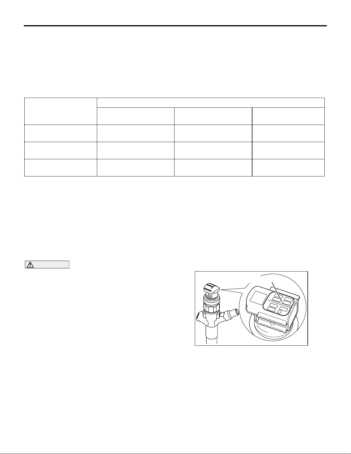
APPLICATION OF ANTI-CORROSION AGENTS AND UNDERCOATS
M1001011000173
If oil or grease gets onto the oxygen sensor, it will
cause a drop in the performance of the sensor.
Cover the oxygen sensor with a protective cover
when applying anti-corrosion agents and undercoats.
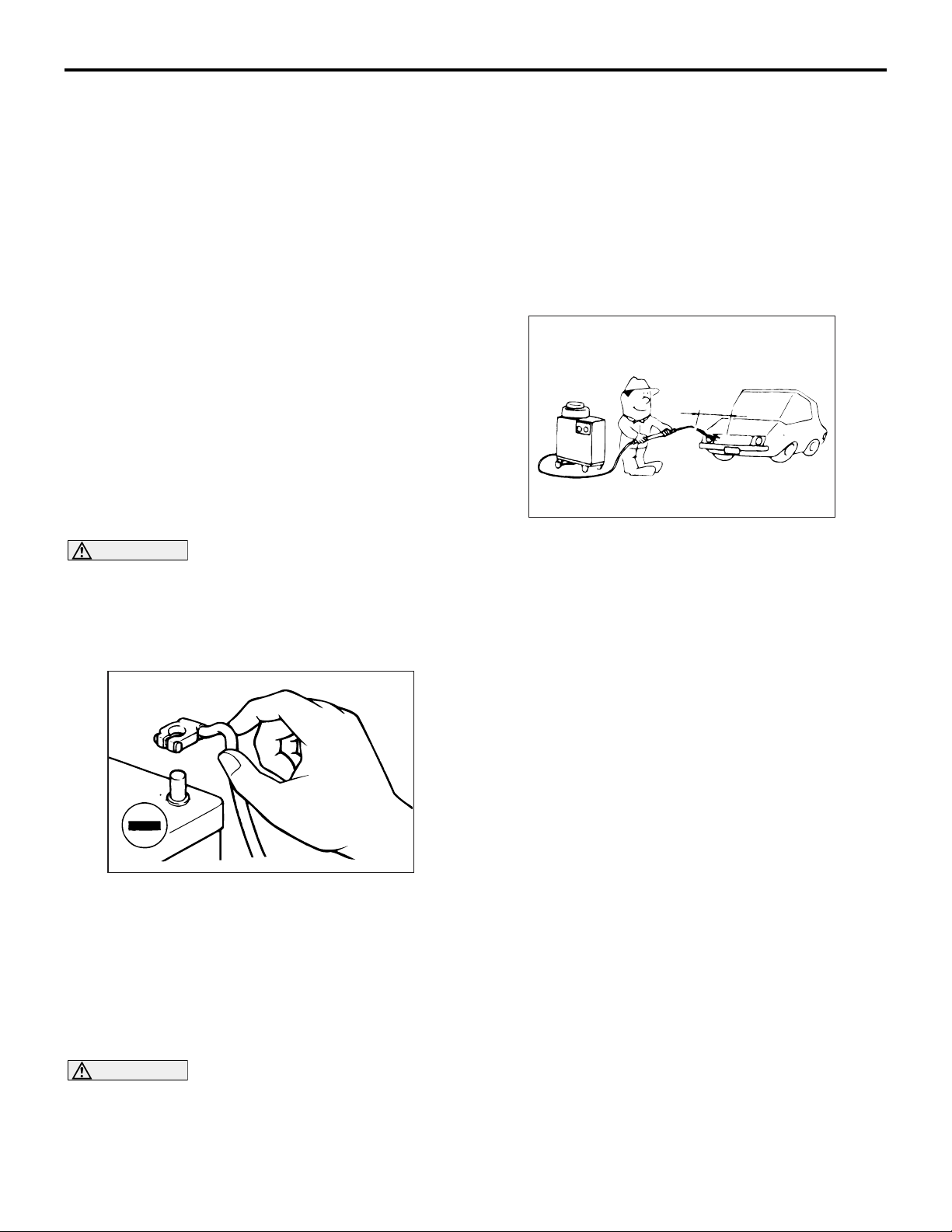
VEHICLE WASHING
M1001012000206
Approximately 40 cm
SERVICING ELECTRICAL SYSTEM
M1001011900217
CAUTION
Before connecting or disconnecting the negative
(
−) cable, be sure to turn off the ignition switch
and the lighting switch (If this is not done, there
is the possibility of semiconductor parts being
damaged).
AC300693
Before replacing a component related to the electrical system and before undertaking any repair procedures involving the electrical system, be sure to first
disconnect the negative (
−) cable from the battery in
order to avoid damage caused by short-circuiting.
VEHICLES WITH SEMI AUTOMATIC AIR CONDITIONER
M1001011300055
CAUTION
Never start the engine with the refrigerant system
empty as it will damage the A/C compressor.
AC300832
AB
If high-pressure car-washing equipment or steam
car-washing equipment is used to wash the vehicle,
be sure to note the following information in order to
avoid damage to plastic components, etc.
• Spray nozzle distance: Approximately 40 cm or
more
• Spray pressure: 3,900 kPa or less
• Spray temperature: 82°C or less
• Time of concentrated spray to one point: within
30 sec.
PRE-INSPECTION CONDITION
M1001012100117
"Pre-inspection condition" refers to the condition that
the vehicle must be in before proper engine inspec
tion can be carried out. If you see the words "Set the
vehicle to the pre-inspection condition" in this man
ual. It means to set the vehicle to the following condition.
• Engine coolant temperature 80 to 90° C
• Lamps, electric cooling fan and all accessories:
OFF
• M/T: Neutral
• A/T: N range
-
-
Page 30
00-28
GENERAL
PRECAUTIONS BEFORE SERVICE
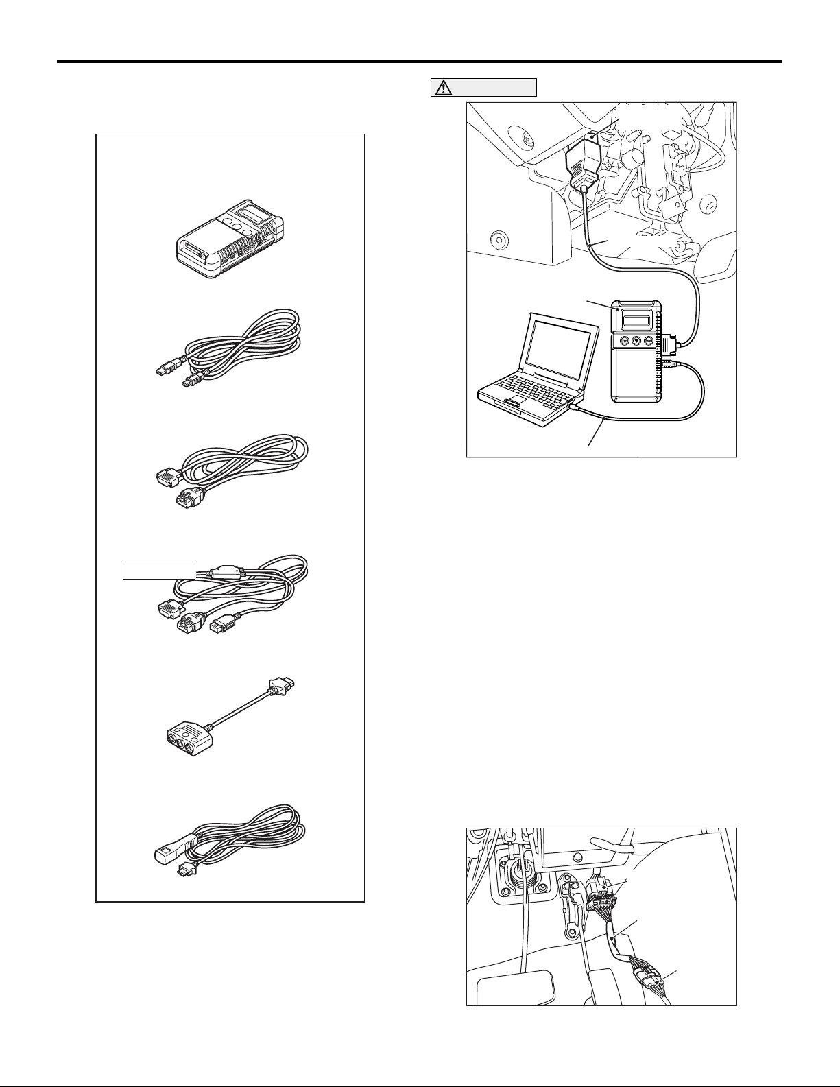
MULTI USE TESTER (M.U.T.-III) SUB ASSEMBLY
M1001012400011
MULTI USE TESTER (M.U.T.-III)
sub assembly
Vehicle communication interface (V.C.I.)
MB991824
M.U.T.-III USB cable
MB991827
M.U.T.-III main harness A
MB991910
M.U.T.-III main harness B
CAUTION
Diagnosis
connector
MB991910
MB991824
MB991827
AC501413
AB
Turn the ignition switch to the "LOCK" (OFF)
position before connecting or disconnecting the
M.U.T.-III.
Connect the M.U.T.-III to the diagnosis connector as
shown in the illustration.
Do not use
MB991911
M.U.T.-III measurement adapter
MB991825
M.U.T.-III trigger harness
MB991826
AC305090
AI
Refer to the "M.U.T.-III OPERATION MANUAL" for
instructions on handling the M.U.T.-III.
HOW TO USE THE THROTTLE CONTROLLER
M1001009300014
As for a vehicle with the electronic control throttle
*
, engine operations such as racing can not be
valve
performed from outside the vehicle. Thus, the throttle
valve controller (MB991791) is provided as a special
tool to enable the engine operation from outside the
vehicle.
NOTE: *: A vehicle with the accelerator pedal position sensor (APS) installed to the accelerator pedal
THE THROTTLE CONTROLLER
CONNECTION
APS harness
side connector
MB991894
MB991791
AC103781
AC
Page 31

GENERAL
PRECAUTIONS BEFORE SERVICE
00-29
1. Disconnect the accelerator pedal position sensor
(APS) connector installed to the accelerator
pedal, and connect the 6-pin connector of throttle
controller adaptor (MB991894) to the vehicle
harness-side connector.
2. Connect the throttle controller (MB991791) to the
8-pin connector of throttle controller adaptor
(MB991894).
IN ORDER TO PREVENT VEHICLES FROM FIRE
M1001011100073
"Improper installation of electrical or fuel related parts
could cause a fire. In order to retain the high quality
and safety of the vehicle, it is important that any
accessories that may be fitted or modifica
tions/repairs that may be carried out which involve
the electrical or fuel systems, MUST be carried out in
accordance with MMC's information/Instructions".
-
ENGINE OILS
M1001011200081
HEALTH WARNING
Prolonged and repeated contact with mineral oil will
result in the removal of natural fats from the skin,
leading to dryness, irritation and dermatitis. In addi
tion, used engine oil contains potentially harmful contaminants which may cause skin cancer. Adequate
means of skin protection and washing facilities must
be provided.
-
RECOMMENDED PRECAUTIONS
The most effective precaution is to adapt working
practices which prevent, as far as practicable, the
risk of skin contact with mineral oils, for example by
using enclosed systems for handling used engine oil
and by degreasing components, where practicable,
before handling them.
Other precautions:
• Avoid prolonged and repeated contact with oils,
particularly used engine oils.
• Wear protective clothing, including impervious
gloves where practicable.
• Avoid contaminating clothes, particularly under-
pants, with oil.
• Do not put oily rags in pockets, the use of overalls
without pockets will avoid this.
• Do not wear heavily soiled clothing and
oil-impregnated foot-wear. Overalls must be
cleaned regularly and kept separately from per
sonal clothing.
• Where there is a risk of eye contact, eye protec-
tion should be worn, for example, chemical goggles or face shields; in addition an eye wash
facility should be provided.
• Obtain First Aid treatment immediately for open
cuts and wounds.
• Wash regularly with soap and water to ensure all
oil is removed, especially before meals (skin
cleansers and nail brushes will help). After clean
ing, the application of preparations containing
lanolin to replace the natural skin oils is advised.
• Do not use petrol, kerosine, diesel fuel, gas oil,
thinners or solvents for cleaning skin.
• Use barrier creams, applying them before each
work period, to help the removal of oil from the
skin after work.
• If skin disorders develop, obtain medical advice
without delay.
-
-
Page 32

00-30
SUPPLEMENTAL RESTRAINT SYSTEM (SRS)
SUPPLEMENTAL RESTRAINT SYSTEM (SRS)
The Supplemental Restraint System (SRS) and seat
belt with pre-tensioner is designed to supplement the
driver's and front passenger's seat belts to help
reduce the risk or severity of injury to the driver and
front passenger by activating and deploying both
front air bags in certain frontal collisions.
The SRS consist of two air bag modules, SRS air
bag control unit (SRS-ECU), front impact sensors,
SRS warning lamp, clock spring and seat belt
pre-tensioner. Front air bags are located in the centre
of the steering wheel and above the glove box. Each
air bag is made up of a folded air bag and an inflator
unit. The SRS-ECU is located for front the floor con
<A/T>
SRS warning lamp
GENERAL
M1001009800150
sole and has a front air bag safing G-sensor, front air
bag analogue G-sensor The front impact sensor is
installed outside of the readlamp sopport panel. The
warning lamp on the instrument panel indicates the
operational status of the SRS. The clock spring is
installed in the steering column. The seat belt
pre-tensioner is built into the driver's and passen
ger's front seat belt retractor.
Only authorized service personnel should do work on
or around the SRS components. Those service per
sonnel should read this manual carefully before starting any such work.
-
Passenger's (front)
air bag module
Driver's air bag
module
-
-
<M/T>
Front impact sensor
AC502001
SRS warning lamp
AC502000
SRS-ECU
SRS-ECU
Seat belt
pre-tensioner
AC500480
Clock spring
AC501190
AC500479
AB
Page 33

GENERAL
SRS SERVICE PRECAUTIONS
SRS SERVICE PRECAUTIONS
DANGER
In order to avoid injury to yourself or others
from accidental deployment of the air bag
during servicing, read and carefully follow all
the precautions and procedures described in
this manual.
CAUTION
Do not use any electrical test equipment on or
near SRS components, except those specified on
.
CAUTION
Never Attempt to Repair the Following Components:
• SRS air bag control unit (SRS-ECU)
• Front impact sensor
• Clock spring
• Driver's and passenger's (front) air bag mod-
ules
• Seat belt with pre-tensioner
NOTE: If any of these components are diagnosed as
faulty, they should only be replaced, in accordance
with the INDIVIDUAL COMPONENTS SERVICE pro
cedures in this manual, starting at page .
SRS-ECU terminal No. Destination of harness Remedy
-
CAUTION
SRS-ECU connector
Do not attempt to repair the wiring harness connectors of the SRS. If a defective wiring harness
is found, repair or replace it by referring to the
table below.
AC103220
00-31
M1001006000155
AC
1, 2 Instrument panel wiring harness →
Front wiring harness
sensor (RH)
3, 4 Instrument panel wiring harness →
Front wiring harness
sensor (LH)
27, 28 Instrument panel wiring harness →
Front wiring harness
pre-tensioner (LH)
29, 30 Instrument panel wiring harness →
Front wiring harness
pre-tensioner (RH)
9, 10 Instrument panel wiring harness →
passenger's (Front) side air bag
module
11, 12 Instrument panel wiring harness →
Clock spring
module
13 Instrument panel wiring harness →
Junction block (fuse No.8)
→ Driver's side air bag
→ Front impact
→ Front impact
→ Seat belt
→ Seat belt
Correct or replace each wiring
harness.
Correct or replace each wiring
harness.
Correct or replace each wiring
harness.
Correct or replace each wiring
harness.
Correct or replace the instrument
panel wiring harness.
Correct or replace instrument panel
wiring harness. Replace the clock
spring.
Correct or replace the instrument
panel wiring harness.
16 Instrument panel wiring harness →
Junction block (fuse No.15)
Correct or replace the instrument
panel wiring harness.
Page 34

00-32
SRS SERVICE PRECAUTIONS
GENERAL
SRS-ECU terminal No. Destination of harness Remedy
8 Instrument panel wiring harness
→SRS wiring lamp
18 Instrument panel wiring harness→
Earth
20 Instrument panel wiring harness →
Diagnosis connector
DANGER
Insulating tape
Battery cable
Battery
AC300580
AB
CAUTION
After disconnecting the battery cable, wait 60
seconds or more before proceeding with the
following work. In addition, insulate the neg
ative battery terminal with a tape. The condenser inside the SRS-ECU is designed to
retain enough voltage to deploy the air bag
for a short time even after the battery has
been disconnected, so serious injury may
result from unintended air bag deployment if
work is done on the SRS system immediately
after the battery cables are disconnected.
CAUTION
The SRS components and seat belt with pre-tensioner should not be subjected to heat, so
remove the SRS-ECU, driver’s and front passen
ger’s air bag modules, clock spring, front impact
sensor, seat belt pre-tensioner before drying or
baking the vehicle after painting.
• Air bag modules: 93° C or more
CAUTION
Whenever you finish servicing the SRS, always
erase the diagnosis code and check warning
lamp operation to make sure that the system
functions properly.
If checks are carried out by using the SRS-ECU
harness connector, observe the following proce
dures: Insert the special tool extra fine probe
(MB992006) into connector from harness side
-
(rear side), and connect the tester to this probe. If
any tool than special tool is used, damage to the
harness and other components will result. Never
insert the probe directly to the terminals from the
front of the connector. The terminals are plated
to increase their conductivity, so that if they are
touched directly by the probe, the plating may
break, which will cause drops in reliability.
Correct or replace the Instrument
panel wiring harness.
Correct or replace the instrument
panel wiring harness.
Correct or replace the instrument
panel wiring harness.
SRS-Harness connector
SRS-ECU harness connector
(rear side)
AC006195
AF
-
Page 35

GENERAL
SUPPORT LOCATIONS FOR LIFTING AND JACKING
00-33
SUPPORT LOCATIONS FOR LIFTING AND JACKING
M1001000700286
SUPPORT POSITIONS FOR A GARAGE JACK AND AXLE STANDS
CAUTION
Do not support the vehicles at locations other than specified supporting points. Doing so will cause
damage, etc.
<2WD>
AXLE STANDS
GARAGE JACK
<Front>
AC502650
AC502651
<Rear>
AC502647
AC502074
AC502069
AC502070
AC502562
AB
Page 36

00-34
<4WD>
AXLE STANDS
GENERAL
SUPPORT LOCATIONS FOR LIFTING AND JACKING
GARAGE JACK
<Front>
AC502650
AC502651
<Rear>
AC502647
AC502069
AC502070
AC502553
AB
Page 37

GENERAL
SUPPORT LOCATIONS FOR LIFTING AND JACKING
00-35
SUPPORT POSITIONS FOR A SINGLE-POST LIFT OR DOUBLE-POST LIFT
CAUTION
When service procedures require removing rear suspension, spare tyre and rear bumper, place additional weight on rear end of vehicle or anchor vehicle to hoist to prevent tipping of centre of gravity
changes.
<2WD>
AC502652
AC502653
AC502571
AB
Page 38

00-36
<4WD>
GENERAL
SUPPORT LOCATIONS FOR LIFTING AND JACKING
AC502652
AC502653
AC502572
AB
Page 39

GENERAL
STANDARD PART/TIGHTENING-TORQUE TABLE
STANDARD PART/TIGHTENING-TORQUE TABLE
Each torque value in the table is a standard value for
tightening under the following conditions.
1. Bolts, nuts and washers are all made of steel and
plated with zinc.
2. The threads and bearing surface of bolts and
nuts are all in dry condition.
The values in the table are not applicable:
STANDARD BOLT AND NUT TIGHTENING TORQUE
Thread size Torque N⋅ m
Bolt nominal
diameter (mm)
M5 0.8 2.5 ± 0.5 5.0 ± 1.0 6.0 ± 1.0
M6 1.0 5.0 ± 1.0 8.5 ± 1.5 10 ± 2
M8 1.25 11 ± 2 20 ± 4 24 ± 4
M10 1.25 23 ± 4 42 ± 8 53 ± 7
Pitch
(mm)
Head mark "4" Head mark "7" Head mark "8"
1. If toothed washers are inserted.
2. If plastic parts are fastened.
3. If bolts are tightened to plastic or die-cast
inserted nuts.
4. If self-tapping screws or self-locking nuts are
used.
00-37
M1001001100715
M12 1.25 42 ± 8 80 ± 10 93 ± 12
M14 1.5 70 ± 10 130 ± 20 150 ± 20
M16 1.5 105 ± 15 195 ± 25 230 ± 30
M18 1.5 150 ± 20 290 ± 40 335 ± 45
M20 1.5 210 ± 30 400 ± 60 465 ± 65
M22 1.5 290 ± 40 540 ± 80 630 ± 90
M24 1.5 375 ± 55 705 ± 105 820 ± 120
FLANGE BOLT AND NUT TIGHTENING TORQUE
Thread size Torque N⋅ m
Bolt nominal
diameter (mm)
M6 1.0 5.0 ± 1.0 10 ± 2 12 ± 2
M8 1.25 13 ± 2 24 ± 4 28 ± 5
M10 1.25 26 ± 5 50 ± 5 58 ± 7
M10 1.5 25 ± 4 46 ± 8 55 ± 5
M12 1.25 47 ± 9 93 ± 12 105 ± 15
M12 1.75 43 ± 8 83 ± 12 98 ± 12
Pitch
(mm)
Head mark "4" Head mark "7" Head mark "8"
NOTE: .
•
Be sure to use only the specified bolts and nuts, and always tighten them to the specified torques.
•
Bolts marked with indications such as 4T or 7T are reinforced bolts. The larger the number, the greater the
bolt strength.
Page 40

NOTES
Page 41

GROUP 11
ENGINE
CONTENTS
ENGINE MECHANICAL <4D5-SOHC>. . . . . . . . . . . . . . . . . . . . 11A
ENGINE OVERHAUL <4D5-SOHC>. . . . . . . . . . . . . . . . . . . . . . 11B
11-1
ENGINE MECHANICAL <4D5-DOHC> . . . . . . . . . . . . . . . . . . . 11C
ENGINE OVERHAUL <4D5-DOHC> . . . . . . . . . . . . . . . . . . . . . 11D
ENGINE MECHANICAL <4M4> . . . . . . . . . . . . . . . . . . . . . . . . . 11E
ENGINE OVERHAUL <4M4> . . . . . . . . . . . . . . . . . . . . . . . . . . . 11F
Page 42

NOTES
Page 43

GROUP 11A
ENGINE
MECHANICAL
<4D5-SOHC>
CONTENTS
11A-1
GENERAL INFORMATION . . . . . . . . 11A-2
SERVICE SPECIFICATIONS. . . . . . . 11A-2
SEALANTS . . . . . . . . . . . . . . . . . . . . 11A-3
SPECIAL TOOLS. . . . . . . . . . . . . . . . 11A-4
ON-VEHICLE SERVICE. . . . . . . . . . . 11A-6
DRIVE BELT TENSION CHECK AND
ADJUSTMENT . . . . . . . . . . . . . . . . . . . . . . 11A-6
VALVE CLEARANCE CHECK AND
ADJUSTMENT . . . . . . . . . . . . . . . . . . . . . . 11A-8
INJECTION TIMING CHECK AND
ADJUSTMENT . . . . . . . . . . . . . . . . . . . . . . 11A-10
IDLE SPEED CHECK . . . . . . . . . . . . . . . . . 11A-12
COMPRESSION PRESSURE CHECK. . . . 11A-12
TIMING BELT TENSION ADJUSTMENT . . 11A-13
TIMING BELT B TENSION ADJUSTMENT 11A-14
CRANKSHAFT PULLEY . . . . . . . . . . 11A-15
REMOVAL AND INSTALLATION . . . . . . . . 11A-15
CAMSHAFT AND VALVE STEM
SEAL . . . . . . . . . . . . . . . . . . . . . . . . . . 11A-18
REMOVAL AND INSTALLATION . . . . . . . . 11A-18
OIL PAN AND OIL SCREEN . . . . . . . 11A-22
REMOVAL AND INSTALLATION . . . . . . . . 11A-22
CRANKSHAFT OIL SEAL . . . . . . . . . 11A-25
REMOVAL AND INSTALLATION . . . . . . . . 11A-25
CYLINDER HEAD GASKET . . . . . . . . 11A-27
REMOVAL AND INSTALLATION . . . . . . . . 11A-27
TIMING BELT . . . . . . . . . . . . . . . . . . . 11A-31
REMOVAL AND INSTALLATION . . . . . . . . 11A-31
TIMING BELT B . . . . . . . . . . . . . . . . . 11A-34
REMOVAL AND INSTALLATION . . . . . . . . 11A-34
ENGINE ASSEMBLY . . . . . . . . . . . . . 11A-36
REMOVAL AND INSTALLATION . . . . . . . . 11A-36
Page 44

11A-2
ENGINE MECHANICAL <4D5-SOHC>
GENERAL INFORMATION
GENERAL INFORMATION
Item 4D56
Total displacement mL 2,477
Bore × Stroke mm 91.1 × 95.0
Compression ratio 21
Combustion chamber Vortex chamber type
Camshaft arrangement SOHC
Number of valve Intake 4
Exhaust 4
Valv e timi ng Intake Opening BTDC 20°
Closing ABDC 49°
Exhaust Opening BBDC 55°
Closing ATDC 2 2 °
Fuel system Distribution type injection pump
Rocker arm Double roller type
M1111000100839
Adjusting screw Elephant foot type
SERVICE SPECIFICATIONS
Items Standard value Limit
Alternator drive belt
(When checked)
Alternator drive belt
(When adjusted)
Alternator drive belt
(When replaced)
Power steering oil pump drive belt
tension (When checked)
Power steering oil pump drive belt
tension (When adjusted)
Power steering oil pump drive belt
tension (When replaced)
Ten s i on N 245 − 441
Deflection mm (Reference) 12.0 −17.0
Ten s i on N 294 − 392
Deflection mm (Reference) 13.0 − 16.0
Ten s i on N 392 − 588
Deflection mm (Reference) 10.0 − 13.0
Ten s i on N 294 − 490
Deflection mm (Reference) 8.0 − 12.0
Ten s i on N 343 − 441
Deflection mm (Reference) 9.0 − 11.5
Ten s i on N 490 − 686
Deflection mm (Reference) 6.0 − 8.0
−
−
−
−
−
−
−
−
−
−
−
−
M1111000300899
A/C compressor drive belt tension
(When checked)
A/C compressor drive belt tension
(When adjusted)
A/C compressor drive belt tension
(When replaced)
Ten s i on N 338 − 430
Deflection mm (Reference) 7.2 − 8.4
Ten s i on N 338 − 430
Deflection mm (Reference) 7.2 − 8.4
Ten s i on N 461 − 614
Deflection mm (Reference) 5.5 − 6.9
−
−
−
−
−
−
Page 45

ENGINE MECHANICAL <4D5-SOHC>
SEALANTS
Items Standard value Limit
Valve clearance (at hot) mm 0.25
Injection timing (Value indicated on dial gauge mm) 9° ATDC (1 ± 0.03)
−
−
11A-3
Idle speed r/min 750 ± 30
Compression pressure kPa (at engine speed of 280 r/min) 3,100 Min. 2,800
Compression pressure difference of all cylinder (at engine speed
of 280 r/min) kPa
Timing belt tension mm 4 − 5
Timing belt B tension mm 4 − 5
−
−
Max. 294
−
−
SEALANTS
M1111000500440
Item Specified Sealant Remark
Semi-circular packing 3M ATD Part No. 8660 or equivalent Semi-drying sealant
Engine oil pan MITSUBISHI GENUINE PART MD970389
or equivalent
Semi-drying sealant
Page 46

11A-4
ENGINE MECHANICAL <4D5-SOHC>
SPECIAL TOOLS
SPECIAL TOOLS
Tool Number Name Use
A
A: MB991824
B: MB991827
C: MB991910
D: MB991911
MB991955
MB991824
B
MB991827
C
MB991910
E: MB991825
F: MB991826
M.U.T.-III sub assembly
A: Vehicle communication
interface (V.C.I.)
B: M.U.T.-III USB cable
C: M.U.T.-III main harness A
(Vehicles with CAN
communication system)
D: M.U.T.-III main harness B
(Vehicles without CAN
communication system)
E: M.U.T.-III measurement
adapter
F: M.U.T.-III trigger harness
• Checking the ignition timing
• Checking the idle speed
For vehicles with CAN
communication, use M.U.T.-III
main harness A to send
simulated vehicle speed. If
you connect M.U.T.-III main
harness B instead, the CAN
communication does not
function correctly.
M1111000601150
CAUTION
D
DO NOT USE
E
F
MB991911
MB991825
MB991826
MB991955
MD998384 Prestroke measuring adapter Adjustment of the injection
timing
D998384
B992040
MB992040 Crank pulley holder Holding the crankshaft sprocket
Page 47

ENGINE MECHANICAL <4D5-SOHC>
SPECIAL TOOLS
Tool Number Name Use
MB990767 Front hub and flange yoke
Holding the camshaft sprocket
holder
B990767
MD998719 Crankshaft pulley holder pin
D998719
MD998381 Camshaft oil seal installer Camshaft oil seal installation
D998381
MD998772 Valve spring compressor Compressing valve spring
11A-5
MD998772
MD998729
D998727
D998781
MD998729 Valve stem seal installer Valve stem seal installation
MD998727 Oil pan FIPG cutter Oil pan removal
MD998781 Flywheel stopper Supporting the flywheel
assembly
MD998376 Crankshaft rear oil seal
installer
Crankshaft rear oil seal
installation
Page 48

11A-6
ENGINE MECHANICAL <4D5-SOHC>
ON-VEHICLE SERVICE
Tool Number Name Use
MD998383 Crankshaft front oil seal
guide
D998383
Crankshaft front oil seal
installation
MD998382 Crankshaft front oil seal
installer
D998382
MD998051 Cylinder head bolt wrench Removal and installation of
cylinder head bolt
MB991614 Angle gauge Tightening cylinder head bolt
MB991614
MB991683 Sling chain set Removal and installation of
B991683
ON-VEHICLE SERVICE
DRIVE BELT TENSION CHECK AND ADJUSTMENT
ALTERNATOR DRIVE BELT TENSION CHECK AND ADJUSTMENT
Check the drive belt tension in the following procedure.
Standard value:
Item When
checked
Tension N 245 − 441 294 − 392 392 − 588
Deflection mm
(Reference)
12.0 −
17.0
When
adjusted
13.0 −
16.0
M1111003100991
When
replaced
10.0 −
13.0
engine assembly
<When using the tension gauge>
Tension gauge
Alternator pulley
Use a belt tension gauge to check that the belt tension is within the standard value.
Water pump
pulley
Crankshaft
pulley
AK403465
AB
Page 49

ENGINE MECHANICAL <4D5-SOHC>
ON-VEHICLE SERVICE
11A-7
<Belt deflection check>
Water pump
Approximately
100 N
Deflection
Alternator pulley
Apply approximately 100 N of force to the middle of
the drive belt between the pulleys (at the place indi
cated by the arrow) and check that the amount of
deflection is within the standard value.
Adjusting
bolt
Alternator
fixing nut
Nut for alternator
pivot bolt
If not within the standard value, adjust the belt tension by the following procedure.
1. Loosen the nut of the nut for alternator pivot bolt.
2. Loosen the alternator fixing nut.
3. Use the adjusting bolt to adjust the belt tension
and belt deflection to the standard values.
4. Tighten the nut of the nut for alternator pivot bolt.
Tightening torque: 44 ± 10 N⋅ m
pulley
Crankshaft
pulley
AK403466
AK403467
AB
AB
POWER STEERING OIL PUMP DRIVE BELT TENSION CHECK
Water pump
pulley
Power steering
pump pulley
Check the drive belt tension in the following proce-
Crankshaft
pulley
AC501167
dure.
Standard value:
Item When
checked
When
adjusted
When
replaced
Tension N 294 − 490 343 − 441 490 − 686
Deflection mm
8.0 − 12.0 9.0 − 11.5 6.0 − 8.0
(Reference)
<When using the tension gauge>
Place a belt tension gauge at the centre of the belt
between the pulleys (arrow), and check that the belt
tension is within the standard value.
<Belt deflection check>
Apply approximately 100 N of pressure against the
location between the pulleys shown by the arrow in
the illustration and then measure the deflection.
If not within the standard value, adjust the belt tension by the following procedure.
AB
5. Tighten the alternator fixing nut.
Tightening torque: 23 ± 2 N⋅ m
6. Tighten the adjusting bolt.
Tightening torque: 5.0 ± 1.0 N⋅ m
CAUTION
Always replace the two V-belts together as a
set, and do not apply any oil to the belts.
A
B
C
AC503534
AB
1. Loosen the power steering oil pump fixing bolts A,
B, and C.
2. Adjust the belt tension by placing a bar or others
to the body of the power steering oil pump, giving
an appropriate tension to the belt by hands.
Page 50

11A-8
ENGINE MECHANICAL <4D5-SOHC>
ON-VEHICLE SERVICE
3. Tighten the fixing bolts in the order of A, B, and C
to the specified torque.
Tightening torque: 23 ± 3 N⋅ m
CAUTION
When checking the belt tension, turn the crankshaft clockwise one turn or more.
4. Check the belt tension, and readjust if necessary.
A/C COMPRESSOR DRIVE BELT TENSION CHECK AND ADJUSTMENT
Tension pulley
Crankshaft pulley
Check the drive belt tension by the following procedures.
Standard value:
Item When
checked
Tension N 338 − 430 338 − 430 461 − 614
Deflection mm
7.2 − 8.4 7.2 − 8.4 5.5 − 6.9
(Reference)
A/C compressor pulley
AC501168
When
adjusted
AB
When
replaced
If not within the standard value, adjust the belt tension by the following procedure.
Tension pulley
Adjusting bolt
AC501168
AC
1. Use the adjusting bolt to adjust the belt tension.
The tension will increase when turning the
adjusting bolt clockwise, and decrease when
turning anti-clockwise.
CAUTION
When checking the belt tension, turn the crankshaft clockwise one turn or more.
2. Check the belt tension, and readjust if necessary.
VALVE CLEARANCE CHECK AND ADJUSTMENT
M1111001500380
1. Start the engine and allow it to warm up until the
engine coolant temperature reaches 80 to 90
2. Remove the timing belt upper cover.
3. Remove the rocker cover.
Timing marks
Timing marks
° C
<When using the tension gauge>
Place a belt tension gauge at the centre of the belt
between the pulleys (arrow), and check that the belt
tension is within the standard value.
<Belt deflection check>
Apply approximately 100 N of pressure against the
location between the pulleys shown by the arrow in
the illustration and then measure the deflection.
Camshaft
sprocket
Crankshaft pulley
AK403468
AB
4. Align the camshaft sprocket timing marks and set
the No. 1 cylinder at top dead centre.
Page 51

ENGINE MECHANICAL <4D5-SOHC>
ON-VEHICLE SERVICE
11A-9
CAUTION
The crankshaft should always be turned in a
clockwise direction.
AK403469 AB
5. Measure the valve clearance at the places
indicated by arrows in the illustration according to
the methods shown below.
Standard value: 0.25 mm
Adjusting
screw
pad
6. If the clearance is outside the standard value,
loosen the lock nut of the rocker arm and adjust
by turning the adjusting screw while using a
thickness gauge to measure the clearance.
7. Tighten the lock nut while holding the adjusting
screw with a screwdriver so that it doesn't turn.
8. Turn the crankshaft 360° clockwise to bring No. 4
cylinder to the top dead centre position.
AK403469 AC
9. Measure the valve clearances at the places
indicated by arrows in the illustration. If the
clearance is not within the standard value, repeat
steps 7 and 8 above.
Thickness
Flat-tipped screwdriver
gauge
AK403470
AB
a. Give a clearance, pushing the pad by a
flat-tipped screwdriver in the opposite
direction of the thickness gauge insertion
as shown in the illustration.
NOTE: Do not damage the pad retainer and
so on when pushing the pad by a
flat-tipped screwdriver.
b. Insert the thickness gauge into the clear-
ance.
AK402925
AK202860AB
10 mm
10 mm
Semicircular
packing
Cylinder head
AK304411
AB
10.Apply specified sealant to the section of the
semi-circular packing shown in the illustration.
Specified sealant: 3M ATD Part No. 8660 or
equivalent
11.Install the rocker cover.
12.Install the timing belt upper cover.
Page 52

11A-10
ENGINE MECHANICAL <4D5-SOHC>
INJECTION TIMING CHECK AND ADJUSTMENT
1. Remove all of the glow plugs.
2. Remove the timing belt upper cover.
ON-VEHICLE SERVICE
M1111001800024
Timing marks
Camshaft
sprocket
Timing marks
Crankshaft pulley
AK403468
AB
3. Align the timing marks of the camshaft sprocket
and set the No. 1 cylinder to the top dead centre
position.
Timing
check plug
AK403474 AB
4. Remove the timing check plug at the rear of the
injection pump.
Nut
Push rod
MD998384
MD998384
AK403476
AB
7. Install the special tool prestroke measuring
adapter (MD998384) to the check plug at the rear
of the injection pump.
Approximately 30˚
AK403477
AB
8. Turn the crankshaft clockwise to move the No. 1
cylinder approximately 30
° before compression
top dead centre.
9. Set the needle of the dial gauge to 0.
10.Check that the needle doesn't move even if the
crankshaft is turned slightly (2
− 3°) in both
clockwise and counterclockwise direction.
NOTE: If the needle moves, the notch is not positioned properly, so once again move the No. 1 cylinder approximately 30° before compression top
dead centre.
10mm
AK403475
AB
5. Before installation of special tool prestroke
measuring adapter (MD998384), make sure that
push rod is protruding by 10 mm. Protrusion of
push rod can be adjusted with an inner nut.
6. Connect the dial gauge to the special tool.
1±0.003mm
Set to 9˚ ATDC
AK403478
AB
11.Turn the crankshaft clockwise to align the No. 1
cylinder to 9
° ATDC.
12.Check that the value indicated on the dial gauge
is at the standard value.
Standard value: 1 ± 0.03 mm
Page 53

ENGINE MECHANICAL <4D5-SOHC>
ON-VEHICLE SERVICE
11A-11
Injection pipe
Nuts
union nuts
Bolts
AK408479
AB
13.If the needle is outside the standard value, adjust
the injection timing by the following procedure.
(1) Loosen the injection pipe union nuts (4 places)
on the injection pump. (Do not remove the
union nuts.)
CAUTION
When loosening the nuts, hold the delivery valve
holders with a spanner so that they don't turn at
the same time.
(2) Loosen the upper mounting nuts and the lower
mounting bolts of the injection pump. (Do not
remove the nut and bolt.)
1±0.03mm or more
1±0.03mm or less
Injection pipe
Nuts
union nuts
Bolts
AK408479
AB
(6) Tighten the mounting nuts to the specified
torque.
Tightening torque: 19 ± 3 N⋅ m
(7) Tighten the mounting bolts to the specified
torque.
Tightening torque: 24 ± 3 N⋅ m
(8) Tighten the injection pump union nuts to the
specified torque.
Tightening torque: 30 ± 7 N⋅ m
CAUTION
When tightening the nuts, hold the delivery valve
holders with a spanner so that they don't turn at
the same time.
14.Remove the special tool prestroke measuring
adapter (MD998384).
Front
View
AK403480
AB
(3) Tilt the injection pump to the left and right and
adjust the needle on the dial gauge so that the
display value is uniform.
(4) Provisionally tighten the mounting nut and bolt
of the injection pump.
(5) Repeat steps 8 − 12 to check if the adjustment
has been made correctly.
Gasket
Timing
check plug
AK403482 AB
15.Install a new gasket to the timing check plug.
16.Tighten the timing check plug to the specified
torque.
Tightening torque: 17 ± 2 N⋅ m
17.Install the timing belt upper cover.
18.Install all of the glow plugs
Tightening torque: 17 ± 2 N⋅ m
Page 54

11A-12
ENGINE MECHANICAL <4D5-SOHC>
ON-VEHICLE SERVICE
IDLE SPEED CHECK
M1111003501141
1. Set the vehicle to the pre-inspection condition.
Diagnosis
connector
MB991910
MB991824
MB991827
Tachometer
AC501413
AB
2. Remove all of the glow plugs.
Injection pump assembly
connector (
12 pin
)
AK403485AB
3. Disconnect the injection pump assembly
connector (12 pin).
NOTE: Doing this will prevent carrying out fuel
injection.
4. Cover the glow plug hole with a shop towel etc.,
and after the engine has been cranked, check that
no foreign material is adhering to the shop towel.
CAUTION
• Keep away from the glow plug hole when
cranking.
•
If compression is measured with water, oil,
fuel, etc., that has come from cracks inside
the cylinder, these materials will become
heated and will gush out from glow plug hole,
which is dangerous.
Compression
gauge
Injection
nozzle
AK403483
AB
2. Turn the ignition switch to "LOOK" (OFF) position,
and connect the diagnosis connector to the
M.U.T.-III.
If the M.U.T.-III is not used, connect a tachometer
to the injection nozzle or the pipe.
3. Start the engine, and let it run at idle.
4. Check the idle speed.
Standard value: 750 ± 30 r/min
5. If the idle speed is not within the standard value,
inspect the diesel system (Refer to GROUP 13A
Troubleshooting
).
Code
− Inspection Chart for Diagnosis
COMPRESSION PRESSURE CHECK
M1111002601327
1. Before inspection, check that the engine oil,
starter and battery are normal. In addition, set the
vehicle to the pre-inspection condition.
AK403486
5. Set compression gauge to one of the glow plug
holes.
6. Crank the engine and measure the compression
pressure.
Standard value (at engine speed of 280
−
r/min): 3,100 kPa
Limit (at engine speed of 280 r/min): min.
2,800 kPa
7. Measure the compression pressure for all the
cylinders, and check that the pressure differences
of the cylinders are below the limit.
Limit: max 294 kPa
AB
Page 55

ENGINE MECHANICAL <4D5-SOHC>
ON-VEHICLE SERVICE
11A-13
8. If there is a cylinder with compression or a
compression difference that is outside the limit,
pour a small amount of engine oil through the
glow plug hole, and repeat the operations in steps
(6) and (7).
(1) If the compression increases after oil is added,
the cause of the malfunction is a worn or
damaged piston ring and/or cylinder inner
surface.
(2) If the compression does not rise after oil is
added, the cause is a burnt or defective valve
seat, or pressure is leaking from the gasket.
9. Connect the injection pump assembly connector
(12 pin).
10.Install the glow plugs.
Tightening torque: 17 ± 2 N⋅ m
TIMING BELT TENSION ADJUSTMENT
M1111002800094
1. Remove the timing belt upper cover.
2. Turn the crankshaft in the clockwise direction and
check the timing belt around its entire
circumference for abnormalities.
4. Loosen the two tensioner mounting bolts 1 or 2
turns.
NOTE: This will allow the tensioner spring to tension the timing belt automatically.
Camshaft spocket
AK403489
AB
5. Turn the crankshaft clockwise and stop at the
second teeth of the camshaft sprocket.
CAUTION
• This will allow the timing belt to be tensioned
by a specified amount, so never overturn the
crankshaft.
•
Never turn the crankshaft counterclockwise.
Timing marks
Timing marks
AK403487
AB
3. Align the timing marks on the sprockets with the
timing mark on the front upper case.
CAUTION
When aligning the timing mark, be sure not to
turn the crankshaft in the counterclockwise
direction as this can cause improper belt ten
-
sion.
Tension side
Bolt A
(slot side)
Bolt A
(slot side)
Bolt B
AK403488
AC
6. To prevent the tensioner bracket from be turned
together with the crankshaft, first tighten slot-side
bolt A to the specified torque, and then tighten bolt
B to the specified torque.
Tightening torque: 26 ± 3 N⋅ m
Bolt B
AK403488
AB
Page 56

11A-14
Deflection
ENGINE MECHANICAL <4D5-SOHC>
ON-VEHICLE SERVICE
CAUTION
When aligning the timing mark, be sure not to
turn the crankshaft in the counterclockwise
direction as this can cause improper belt ten
sion.
-
AK403491
AB
7. Turn the crankshaft counterclockwise to align the
timing marks. Push down belt at a point halfway
with a forefinger to check that defection of belt is
up to standard value.
Standard value: 4.0 − 5.0 mm
8. Mount the timing belt upper cover.
TIMING BELT B TENSION ADJUSTMENT
M1111004900019
1. Remove timing belt upper cover.
2. Turn the crankshaft in the clockwise direction and
check the timing belt around its entire
circumference for abnormalities.
Timing marks
Timing marks
AK403487
3. Align the timing marks on the sprockets with the
timing mark on the front upper case.
AB
Access cover
AK403492
AB
4. Remove the access cover.
Pivot side bolt
Slot side nut
AK403493
AB
5. Loosen the tensioner pivot side bolt 1 turn and
slot side nut 1 or 2 turns.
NOTE: These works will allow the tensioner
spring to tension timing belt B automatically.
6. First tighten tensioner slot side nut, and then
tighten pivot side bolt to the specified torque.
Tightening torque:
Pivot side bolt 23 ± 3 N⋅ m
Slot side nut 26 ± 3 N⋅ m
Access cover
Guide
AK403494
AB
7. Install the access cover while sliding the front
lower cover down along the two guides.
8. Install the timing belt upper cover.
Page 57

ENGINE MECHANICAL <4D5-SOHC>
CRANKSHAFT PULLEY
CRANKSHAFT PULLEY
11A-15
REMOVAL AND INSTALLATION
M1112001600959
Pre-removal Operation
• Engine Room Under Cover Removal (Refer to GROUP 51
− Under Cover ).
25 ± 4 N·m
185 ± 5 N·m
Post-installation Operation
• Drive Belt Tension Check and Adjustment (Refer to
P.11A-6).
• Engine Room Under Cover Installation (Refer to GROUP
51
− Under Cover ).
7
4
<<A>>
<<B>>
<<C>>
5
2
(Engine oil)
6
3
1
AB
Removal steps
1. A/C compressor drive belt
2. Power steering oil pump drive belt
3. Alternator drive belts
4. Crankshaft pulley (for A/C)
<<D>> >>A<<
>>A<<
>>A<<
AC501887
Removal steps (Continued)
5. Crankshaft pulley centre bolt
6. Special washer
7. Crankshaft pulley
Page 58

11A-16
ENGINE MECHANICAL <4D5-SOHC>
CRANKSHAFT PULLEY
REMOVAL SERVICE POINTS
<<A>> A/C COMPRESSOR DRIVE BELT
REMOVAL
<<C>> ALTERNATOR DRIVE BELTS
REMOVAL
CAUTION
To reuse the drive belt, draw an arrow indicating
the rotating direction (to the right) on the back of
the belt using chalk, etc.
Adjusting bolt
A/C compressorCrankshaft pulley
AC503581
AB
Turn the adjusting bolt anti-clockwise (in the left
turn), and remove the drive belt.
<<B>> POWER STEERING OIL PUMP
DRIVE BELT REMOVAL
CAUTION
To reuse the drive belt, draw an arrow indicating
the rotating direction (to the right) on the back of
the belt using chalk, etc.
Adjusting
bolt
Alternator
fixing nut
Nut for alternator
pivot bolt
AC503982
AB
1. Loosen the nut for alternator pivot bolt and locking
bolt.
CAUTION
To reuse the drive belt, draw an arrow indicating
the rotating direction (to the right) on the back of
the belt using chalk, etc.
2. Turn the adjusting bolt anti-clockwise (in left turn),
and remove the drive belt.
<<D>> CRANKSHAFT PULLEY CENTRE
BOLT REMOVAL
A
B
C
AC503534
AB
Loosen the mounting bolts shown in the figure to
remove the drive belt.
MB992040
AC502472
AB
1. Use special tool crank pulley holder (MB992040),
hold the crankshaft pulley.
2. Remove the crankshaft pulley centre bolt.
Page 59

ENGINE MECHANICAL <4D5-SOHC>
CRANKSHAFT PULLEY
11A-17
INSTALLATION SERVICE POINT
>>A<< CRANKSHAFT PULLEY/SPECIAL
WASHER/CRANKSHAFT PULLEY CEN
-
TRE BOLT INSTALLATION
Crankshaft
pulley centre
bolt
Special washer
1. Clean and then degrease the crankshaft sprocket
contacting surface of the crankshaft pulley.
NOTE: Degreasing is necessary to prevent
decrease in the friction between contacting sur
faces.
Crankshaft
pulley
Clean
Degrease
Crankshaft
AC503579
AB
-
2. Clean the bolt hole in the crankshaft, the
crankshaft contacting surface and special washer
contacting surface of the crankshaft pulley, and
the special washer.
3. Apply an appropriately small amount of oil to the
threads and seating surface of the crankshaft
pulley centre bolt.
MB992040
AC502472
AB
4. Use special tool crank pulley holder (MB992040)
as in the removal procedure to retain crankshaft
pulley, and tighten crankshaft pulley centre bolt to
the specified torque.
Tightening torque: 185 ± 5 N⋅ m
Page 60

11A-18
ENGINE MECHANICAL <4D5-SOHC>
CAMSHAFT AND VALVE STEM SEAL
CAMSHAFT AND VALVE STEM SEAL
REMOVAL AND INSTALLATION
M1112006600987
CAUTION
*Remove and assemble the marked parts in each cylinder unit.
Apply engine oil to all
moving parts before
installation.
10 mm
7
10
Sealant: 3M ATD Part No. 8660 or
equivalent
2
10 mm
AC503599
7
N
9
37 ± 2 N·m
20 ± 1 N·m
6
8
5.9 ± 1.0 N·m
11 ± 1 N·m
N
10
37 ± 2 N·m
13
14
1
11 ± 1 N·m
11 ± 1 N·m
11 ± 1 N·m
>>E<<
N
12
11
5
69 ± 5 N·m
43
Camshaft removal steps
1. Control wiring harness connector
2. Battery wiring harness connector
3. Crank angle position sensor
connector
4. Crank angle position sensor
connector clamp
5. Timing belt front upper cover
6. Breather hose connection
7. Rocker cover
8. Oil filler cap
<<A>> >>H<<
>>G<<
<<B>> >>D<<
>>F<<
16*
15
17*
18*
19*
N
20*
AC502018
Camshaft removal steps
9. Rocker cover gasket
10. Semi-circular packing
Valve clearance adjustment
•
(Refer to
11. Camshaft sprocket
12. Camshaft oil seal
13. Rocker arm and shaft assembly
14. Camshaft bearing caps
15. Camshaft
P.11A-8).
AB
Page 61

Valve stem seal removal steps
1. Control wiring harness connector
2. Battery wiring harness connector
3. Crank angle position sensor
connector
4. Crank angle position sensor
connector clamp
>>E<<
<<B>> >>D<<
<<C>> >>C<<
>>B<<
>>A<<
5. Timing belt front upper cover
6. Breather hose connection
7. Rocker cover
9. Rocker cover gasket
13. Rocker arm and shaft assembly
Windshield wiper (Refer to
•
GROUP 51
Cowl top panel
•
16. Valve spring retainer locks
17. Valve spring retainers
18. Valve springs
19. Valve stem seals
20. Valve spring seats
− Windshield wiper ).
REMOVAL SERVICE POINTS
ENGINE MECHANICAL <4D5-SOHC>
CAMSHAFT AND VALVE STEM SEAL
2. Secure the camshaft sprocket and the valve
timing belt with cable bands to prevent deviation
from the relative positions between the camshaft
sprocket and the valve timing belt.
MB990767
Cable tie wrap
Camshaft sprocket
11A-19
AC502476
AB
<<A>> CAMSHAFT SPROCKET
REMOVAL
CAUTION
Always turn the crankshaft in the forward direction (clockwise).
Timing marks
AC503587
1. Turn the crankshaft in the forward direction
(clockwise) to align the timing mark so that No.1
cylinder is at the compression TDC (Top Dead
Centre) position.
AB
MD998719
AC503762
AB
3. Use the following special tools to stop the
camshaft sprocket from turning.
• Front hub and flange yoke holder (MB990767)
• Crankshaft pulley holder pin (MD998719)
CAUTION
Do not turn the crankshaft after the camshaft
sprocket is removed.
4. Remove the camshaft sprocket with the valve
timing belt attached.
<<B>> ROCKER ARM AND SHAFT
ASSEMBLY REMOVAL
CAUTION
Never disassemble the rocker arm and shaft
assembly.
Loosen the rocker arm and shaft assembly mounting
bolt, and then remove the rocker arm and shaft
assembly with the bolt still attached.
Page 62

11A-20
ENGINE MECHANICAL <4D5-SOHC>
CAMSHAFT AND VALVE STEM SEAL
<<C>> VALVE SPRING RETAINER LOCKS
REMOVAL
CAUTION
When removing valve spring retainer lock, leave
the piston of each cylinder in the TDC position.
The valve may fall into the cylinder if the piston is
not properly in the TDC position.
MD998772
AC502475
Use special tool valve spring compressor
(MD998772) to compress the valve spring, remove
the valve spring retainer lock.
AB
>>B<< VALVE SPRINGS INSTALLATION
Rocker arm side
Identification
colour
AC201453
AD
Install the valve spring with its identification colour
painted end facing the rocker arm.
>>C<< VALVE SPRING RETAINER LOCKS
INSTALLATION
INSTALLATION SERVICE POINTS
>>A<< VALVE STEM SEALS INSTALLA-
TION
1. Apply a small amount of engine oil to the valve
stem seal.
CAUTION
Valve
Valve spring
seat
Valve guide
• Valve stem seal cannot be reused.
• Special tool valve stem seal installer
(MD998729) must be used to install the valve
stem seal. Improper installation could result
in oil leaking past the valve guide.
2. Use special tool to fill a new valve stem seal in the
valve guide using the valve stem area as a guide.
MD998729
Valve stem
seal
AC308920
AC
MD998772
AC502475
AB
Use special tool valve spring compressor
(MD998772) to compress the valve spring in the
same manner as removal, and install the valve
spring retainer lock.
>>D<< ROCKER ARM AND SHAFT
ASSEMBLY INSTALLATION
1. Install the rocker arm and shaft assembly to the
bearing caps.
Chamfer
AC503766
AB
2. Set the washer so that it faces in the direction
shown in the illustration, and then install the bolt.
Page 63

ENGINE MECHANICAL <4D5-SOHC>
CAMSHAFT AND VALVE STEM SEAL
11A-21
>>E<< TIMING BELT FRONT UPPER
COVER INSTALLATION
1
1
3
2
AC503597
1
AB
Install the bolts to the timing belt front upper cover at
the shown position.
No. Bolt diameter × length mm
1 6 × 22
2 6 × 50
3 6 × 60
>>F<< CAMSHAFT BEARING CAPS
INSTALLATION
>>G<< CAMSHAFT OIL SEAL
INSTALLATION
MD998381
Oil seal
1. Apply new engine oil to the camshaft oil seal lip.
2. Use special tool camshaft oil seal installer
(MD998381) to press-fit the camshaft oil seal.
Camshaft
AC502587
AB
>>H<< CAMSHAFT SPROCKET
INSTALLATION
MB990767
Cap numbers
2
Front of engine
3
4
AC503779
AB
The cap numbers are embossed on the top surface
of the bearing caps, so install in the order of the num
bers. However, no numbers are embossed on bearing caps 1 and 5.
MD998719
AC503762
1. Use the following special tools to stop the
camshaft sprocket from turning in the same way
as was done during removal.
• Front hub and flange yoke holder (MB990767)
• Crankshaft pulley holder pin (MD998719)
-
2. Tighten the timing belt train bolt to the specified
torque.
Tightening torque: 69 ± 5 N⋅ m
AB
Page 64

11A-22
ENGINE MECHANICAL <4D5-SOHC>
OIL PAN AND OIL SCREEN
OIL PAN AND OIL SCREEN
REMOVAL AND INSTALLATION
M1112002500319
Pre-removal Operation
• Engine Room Under Cover Removal (Refer to GROUP 51
− Under Cover ).
• Engine Oil Draining (Refer to GROUP 12 − On-vehicle
Service, Engine Oil Replacement
).
Post-installation Operation
• Engine Oil Refilling (Refer to GROUP 12 − On-vehicle
Service, Engine Oil Replacement
• Engine Room Under Cover Installation (Refer to GROUP
51
− Under Cover ).
).
5
39 ± 5 N·m
3
>B<<
N
9
19 ± 3 N·m
1
N
2
9.0 ± 3.0 N·m
9.0 ± 1.0 N·m
Removal steps
1. Engine oil pan drain plug
2. Engine oil pan drain plug gasket
3. Alternator vacuum pump oil return
hose connection
4. Flywheel housing front lower
cover
5. Engine oil level gauge
4
9.0 ± 1.0 N·m
<<A>>
<<B>>
<<B>>
<<B>>
<<C>> >>A<<
19 ± 3 N·m
8
6
7
AC501853
Removal steps (Continued)
Steering column shaft assembly
•
and shaft assembly connecting
bolt
Power steering gear box
•
connecting bolts
Return tube clamp
•
Pressure tube clamp
•
6. Engine oil pan and engine oil pan
strainer assembly
AB
Page 65

ENGINE MECHANICAL <4D5-SOHC>
OIL PAN AND OIL SCREEN
11A-23
Removal steps (Continued)
7. Engine oil pan
8. Engine oil pan strainer
9. Engine oil pan strainer gasket
REMOVAL SERVICE POINTS
<<A>> STEERING COLUMN SHAFT
ASSEMBLY AND SHAFT ASSEMBLY
CONNECTING BOLT DISCONNECTION
<R.H. fender side>
Shaft assembly
connecting bolt
18 ± 2 N·m
Upper arm (R.H.)
Disconnect the steering column shaft and the shaft
assembly.
AC502232
AB
CAUTION
A
MD998727
B
AC504256AB
MD998727
AC104547
AC
<<B>> POWER STEERING GEAR BOX
CONNECTING BOLTS/RETURN TUBE
CLAMP/PRESSURE TUBE CLAMP
REMOVAL
AC502231
Remove the mounting bolts of the power steering
gear box and of the tube clamp, and hung the power
steering gear box using a wire or other similar mate
rial.
AB
<<C>> ENGINE OIL PAN AND ENGINE
OIL PAN STRAINER ASSEMBLY
REMOVAL
1. Remove the engine oil pan mounting bolts.
Do not use special tool oil pan FIPG cutter
(MD998727) in area A of the oil pan. Using the
special tool in area A may cause deformation of
the front case because the front case is made of
aluminium.
2. Tap special tool MD998727 into the range (B)
between the cylinder block and the oil pan, and
then slide the tool sideways.
NOTE: If any sounding parts interfere with the
removal, there is no need to use special tool
MD998727.
3. With the oil pan separated from the cylinder block,
remove the oil screen assembly mounting bolts,
and then remove the oil pan together with the oil
screen assembly.
INSTALLATION SERVICE POINTS
>>A<< ENGINE OIL PAN AND ENGINE
-
OIL PAN STRAINER ASSEMBLY INSTAL
LATION
1. Remove sealant from the engine oil pan and
cylinder block surfaces.
-
Page 66

11A-24
Ø4 mm
ENGINE MECHANICAL <4D5-SOHC>
OIL PAN AND OIL SCREEN
CAUTION
Then wait at least one hour. Never start the
engine or let engine oil or coolant touch the seal
ant surface during that time.
4. Tighten the engine oil pan bolts to the specified
torque.
Tightening torque: 9.0 ± 3.0 N⋅ m
-
Groove
Bolt hole
AC503481
AB
2. Apply a bead of the sealant to the cylinder block
mating surface of the engine oil pan as shown.
Specified sealant: MITSUBISHI GENUINE
PART MD970389 or equivalent
NOTE: Install the engine oil pan within 15 minutes
after applying sealant.
3. Assemble the engine oil pan to the cylinder block.
>>B<< ENGINE OIL PAN DRAIN PLUG
GASKET INSTALLATION
Engine oil pan side
AC102325
Replace the gasket with a new gasket. Install the
new gasket in the direction shown in the illustration.
AI
Page 67

ENGINE MECHANICAL <4D5-SOHC>
CRANKSHAFT OIL SEAL
CRANKSHAFT OIL SEAL
11A-25
REMOVAL AND INSTALLATION
M1112003101094
132 ± 5 N·m
11 ± 1 N·m
5
N
6
4
N
N
8
3
7
2
8
1
>>D<<
N
2
Crankshaft front oil removal
steps
Timing belt B (Refer to P.11A-34).
•
1. Crankshaft sprocket B
2. Crankshaft front oil seal
Crankshaft rear oil seal
removal steps
Transmission assembly (Refer to
•
GROUP 22A
assembly
).
− Transmission
(Lip section) (Lip section)
<<A>> >>C<<
>>B<<
>>A<<
Engine oil
AC502585
Crankshaft rear oil seal
removal steps (Continued)
3. Flywheel assembly
4. Ball bearing
5. Oil seal case
6. Gasket
7. Oil separator
8. Crankshaft rear oil seal
AB
Page 68

11A-26
ENGINE MECHANICAL <4D5-SOHC>
CRANKSHAFT OIL SEAL
REMOVAL SERVICE POINT
<<A>> FRYWHEEL ASSEMBLY
REMOVAL
MD998781
AC503817
1. Use the special tool flywheel stopper
(MD998781), hold the flywheel.
2. Remove the flywheel assembly.
AB
INSTALLATION SERVICE POINTS
>>A<< CRANKSHAFT REAR OIL SEAL
INSTALLATION
Push the oil separator into the oil seal case, with its
oil hole at the case bottom (indicated by an arrow in
illustration).
>>C<< FLYWHEEL ASSEMBLY
INSTALLATION
MD998781
AC503817
1. Use special tool flywheel stopper (MD998781) to
secure the flywheel assembly in the same manner
as removal.
2. Tighten the flywheel bolts to the specified torque.
Tightening torque: 132 ± 5 N⋅ m
AB
MD998376
AC503776
AB
Use the special tool crankshaft rear oil seal installer
(MD998376), press-fit the rear oil seal in the oil seal
case.
>>B<< OIL SEPARATOR INSTALLATION
Oil seal case Oil separator
>>D<< CRANKSHAFT FRONT OIL SEAL
INSTALLATION
Crankshaft
MD998382
Oil seal
MD998383
(Apply oil to outer surface)
1. Attach special tool crankshaft front oil seal guide
(MD998383) to the crankshaft and apply engine
oil to the outer surface of the tool.
2. Using special tool crankshaft front oil seal installer
(MD998382), press-fit the front oil seal into the
front lower case.
Front lower
case
Oil pump
drive shaft
AC503778
AB
Oil pan mounting surface
Oil hole
AC503777
AB
Page 69

ENGINE MECHANICAL <4D5-SOHC>
CYLINDER HEAD GASKET
CYLINDER HEAD GASKET
11A-27
REMOVAL AND INSTALLATION
29 ± 2 N·m to 122˚ - +124˚
(During cold engine)
(Engine oil)
10
23 ± 3 N·m
23 ± 3 N·m
23 ± 3 N·m
11
23 ± 3 N·m
N
13
M1112004001692
6
5
12
5.0 ± 1.0 N·m
5.0 ± 1.0 N·m
7
5.0 ± 1.0 N·m
4
30 ± 7 N·m
8
3
9
12 ± 1 N·m
<<A>> >>D<<
Removal steps
1. Oil level gauge and guide
assembly
2. O-ring
3. Radiator upper hose
Rocker cover (Refer to
•
P.11A-18).
4. Engine coolant temperature
gauge unit connector
5. Engine coolant temperature
sensor connector
6. Glow plug terminal
<<B>> >>C<<
<<C>>
<<D>> >>B<<
>>A<<
1
N
2
Removal steps (Continued)
7. Fuel injection pipes
8. By-pass hose connection
9. Fuel hose
Water pipe C (Refer to GROUP
•
14
− Water hose and water pipe ).
10. Power steering oil pump
assembly
11. Power steering oil pump bracket
12. Cylinder head assembly
13. Cylinder head gasket
(Engine oil)
AC502586
AB
Page 70

11A-28
ENGINE MECHANICAL <4D5-SOHC>
CYLINDER HEAD GASKET
REMOVAL SERVICE POINTS
<<A>> RADIATOR UPPER HOSE DISCON-
NECTION
After making mating marks on the radiator upper
hose and the hose clamp, disconnect the radiator
upper hose.
<<B>> FUEL INJECTION PIPES
REMOVAL
CAUTION
After disconnecting the injection pipe, plug the
opening so that no foreign particles get inside
the pump or into the injection nozzle.
Nut
Delivery holder
AC503283
AB
<<C>> POWER STEERING OIL PUMP
ASSEMBLY REMOVAL
1. Remove the power steering oil pump assembly
from the bracket with the hose attached.
2. Place the removed power steering oil pump
assembly in a place where it will not be a
hindrance when removing and installing the
engine assembly, and tie it with cord.
<<D>> CYLINDER HEAD ASSEMBLY
REMOVAL
MD998051
AC502540
When loosening nuts at both ends of injection pipe,
hold the delivery holder (for pump side) and the
injection nozzle assembly (for nozzle side) with
wrench and loosen nut.
6
2
1
Front of engine
10
9
5
14
13
18
17
16
15
12
11
4
8
7
AC503868
AC503912
3
AB
Using special tool cylinder head bolt wrench
(MD998051), loosen the cylinder head bolts in two or
three steps in the order of the numbers shown in the
illustration.
Page 71

ENGINE MECHANICAL <4D5-SOHC>
INSTALLATION SERVICE POINTS
CYLINDER HEAD GASKET
11A-29
>>A<< CYLINDER HEAD GASKET
INSTALLATION
CAUTION
The thickness of the original cylinder head gasket is selected according to the protrusion
amount of the piston. Therefore, if the piston or
the connecting rod is replaced, the protrusion
amount may be changed. Always select a correct
gasket by measuring the protrusion amount.
(Refer to GROUP 11B>
Valves
).
A
− Cylinder Head and
Identification mark
CAUTION
Do not allow foreign material to enter the engine
coolant or oil passages and the cylinder.
2. Clean the cylinder head assembly and the
cylinder block mating surfaces with a scraper or a
wire brush.
Cylinder head
bolt washer
Chamfered
side
AC503931AB
3. Install the cylinder head bolt washer to the
cylinder head bolt so that the washer chamfered
side faces as shown.
4. Apply a small amount of engine oil to the cylinder
head bolt thread and the washer.
B
C
AC503769
AB
When replacing the cylinder head gasket only, confirm the gasket identification mark, and then select a
replacement part according to the following table.
Spec Identification mark (size) Part number
A D5-774 (fitted thickness 1.45 ±
MD377774
0.04)
B D5-774 (fitted thickness 1.50 ±
MD377775
0.04)
C D5-774 (fitted thickness 1.55 ±
MD377776
0.04)
>>B<< CYLINDER HEAD ASSEMBLY
INSTALLATION
1. Select a cylinder head gasket of correct
specification.
MD998051
AC502540
13
17
18
Front of engine
9
10
14
5
3
1
2
6
11
15
7
8
4
12
AC503868
AC503912
16
AC
5. Tighten the cylinder head bolts according to the
following procedure (angle-tightening procedure).
(1) Use special tool cylinder head bolt wrench
(MD998051) to tighten the cylinder head bolts
in the order of illustrated numbers to 29
⋅ m.
N
± 2
Page 72

11A-30
ENGINE MECHANICAL <4D5-SOHC>
CYLINDER HEAD GASKET
CAUTION
• If the cylinder head bolt is tightened less than
the specified lower limit of 120 degree angle,
the bolt may become loose. Be sure to tighten
correctly.
•
If the cylinder head bolt is tightened in excess
of the specified upper limit of 124 degree
angle, loosen the bolt completely and repeat
the entire procedures.
>>C<< FUEL INJECTION PIPES
INSTALLATION
When tightening the nuts at both ends of the fuel
injection pipe, hold the delivery holder (for pump
side) and the injection nozzle assembly (for nozzle
side) with a wrench, and tighten the nuts to the spec
ified torque.
Tightening torque: 30 ± 7 N⋅ m
-
MB991614
MD998051
AC502541
13
17
18
Front of engine
9
10
14
5
3
1
2
6
11
15
7
8
4
16
12
AC503868
AC503913
AB
(2) Using special tool angle gauge (MB991614),
tighten the cylinder head bolts in the illustrated
sequence by a further 120 to 124 degree
angle.
>>D<< RADIATOR UPPER HOSE
CONNECTION
To reuse the radiator upper hose, align the mating
marks that were made during removal, and then
install the hose clamp.
Page 73

ENGINE MECHANICAL <4D5-SOHC>
TIMING BELT
TIMING BELT
11A-31
REMOVAL AND INSTALLATION
M1112004301358
Pre-removal Operation
• Cooling Fan Removal (Refer to GROUP 14 − Radiator Fan
).
2
3
26 ± 3 N·m
11 ±1 N·m
11 ±1 N·m
Post-installation Operation
• Cooling Fan Installation (Refer to GROUP 14 − Radiator
Fan
).
• Drive Belt Tension Check and Adjustment (Refer to
P.11A-6).
11
10
9
26 ± 3 N·m
7
11 ±1 N·m
11 ±1 N·m
>>B<<
>>B<<
1
9.0 ± 1.0 N·m
8
5
11 ±1 N·m
Removal steps
1. Crank angle sensor connector
2. Battery wiring harness connector
3. Timing belt front upper cover
4. Tension pulley and tension pulley
bracket assembly
5. Timing belt front lower cover
22 ± 4 N·m
<<A>>
6
>>A<<
4
AC502129
Removal steps (Continued)
6. Crank angle sensor
7. Crankshaft sensing blade
8. Timing belt
9. Tensioner spacer
10. Tensioner spring
11. Timing belt tensioner
AB
Page 74

11A-32
ENGINE MECHANICAL <4D5-SOHC>
TIMING BELT
REMOVAL SERVICE POINT
<<A>> TIMING BELT REMOVAL
1. When reinstalling timing belt, mark an arrow at the
belt to show rotation direction.
Tilt to water pump side
A
B
AC503588
2. Loosen the timing belt tensioner mounting bolt A
and B.
3. Push timing belt tensioner to water pump side and
tighten the timing belt tensioner mounting bolt A
and B. Secure so that timing tensioner will not
move back.
AB
1. Align the timing marks of the 3 sprocket.
2. When reusing timing belt, make sure the arrow
mark is pointing in the same direction as when the
belt was removed.
CAUTION
1. Engage the belt on the various sprockets
while maintaining tension on the belt of ten
sion side.
2. Align the injection pump sprocket with the
timing mark, hold the sprocket so that is does
not turn and engage the belt.
Timing
marks
Camshaft
sprocket
Tension
side
Timing
marks
-
INSTALLATION SERVICE POINTS
>>A<< TIMING BELT INSTALLATION
Timing
marks
Timing
marks
Camshaft
sprocket
Fuel injection
pump sprocket
Timing
marks
Crankshaft
sprocket
AC504264
AB
Fuel injection
pump sprocket
Timing
marks
Crankshaft
sprocket
AC501169
AB
3. Install the timing belt to the crankshaft sprocket, to
injection pump sprocket, to tensioner and to
camshaft sprocket in that order. Being careful not
to allow deflection on the tension side of the
timing belt.
4. Loosen the tensioner mounting bolts and apply
tension with the spring.
Page 75

ENGINE MECHANICAL <4D5-SOHC>
TIMING BELT
11A-33
CAUTION
1. When turning the crankshaft in step 5, strictly
observe the specified amount of rotation (2
teeth on the camshaft sprocket) in order to
apply a constant force to the tension side of
the belt.
2. Do not turn the crankshaft anti-clockwise.
3. Do not touch the belt buring adjustment.
Camshaft sprocket
2 teeth
AC503593
AB
5. Turn the crankshaft clockwise and stop at the
second lobe of the camshaft sprocket.
A
Tensioner
mounting bolt
Amount of belt
deflection
AC503595
AB
9. Press on the centre of the bolt with an index finger
to check the amount of deflection.
Standard value: 4 − 5 mm
>>B<< TIMING BELT FRONT LOWER
COVER/TIMING BELT FRONT UPPER
COVER INSTALLATION
1
1
2
1
Tensioner
Tensioner
mounting bolt
AC503594
AB
6. Make sure that the part indicated by arrow A does
not float upward.
7. Tighten the tensioner mounting bolts, starting with
the bolt in the elongated hole. If the lower bolt is
tightened first, belt tension will become too tight.
8. Turn the crankshaft anti-clockwise and align the
timing mark. Next, make sure that the timing
marks of all sprockets are aligned.
3
1
1
1
2
1
AC503596
AB
Install the bolts to the timing belt front lower cover
and timing belt front upper cover at the shown posi
tion.
No. Bolt diameter × length mm
1 6 × 22
2 6 × 50
3 6 × 60
-
Page 76

11A-34
ENGINE MECHANICAL <4D5-SOHC>
TIMING BELT B
TIMING BELT B
REMOVAL AND INSTALLATION
5
N
4
3
2
26 ± 3 N·m
M1112004600185
7
6
1
Removal steps
Timing belt (Refer to P.11A-31).
•
1. Crankshaft sprocket
2. Flange
<<A>> >>A<<
3. Timing belt B
REMOVAL SERVICE POINT
<<A>> TIMING BELT B REMOVAL
1. When reinstalling timing belt B, mark an arrow at
the belt to show rotation direction.
Water pump
A
B
AC502130
Removal steps (Continued)
4. Gasket
5. Tensioner spacer B
6. Tensioner spring B
7. Timing belt tensioner B
AB
3. Push timing belt tensioner to water pump side and
tighten the timing belt tensioner mounting bolt A
and nut B. Secure so that timing belt tensioner will
not move back.
AC503589
AB
2. Loosen the timing belt tensioner mounting bolt A
and nut B.
Page 77

ENGINE MECHANICAL <4D5-SOHC>
TIMING BELT B
11A-35
INSTALLATION SERVICE POINT
>>A<< TIMING BELT B INSTALLATION
Timing marks
A
Timing belt
tensioner B
Timing
marks
Timing
marks
1. Align the timing marks of the 3 sprocket.
2. When reusing timing belt B, make sure the arrow
mark is pointing in the same direction as when the
belt was removed.
B
AC504265
AB
3. Install timing belt B and make sure there is no
deflection on the tension side.
4. Press the deflection side of timing belt B with the
hand and fully stretch the tensioner side.
5. Make sure that the timing marks are aligned.
6. Loosen the tensioner mounting bolt and nut so
that only the pressure of the spring is applied to
timing belt B.
7. Tighten the tensioner mounting bolt A and nut B,
tightening the nut first. If the bolt is tightened first,
the tensioner will move and tension the belt.
Tightening torque: 26 ± 3 N⋅ m
Countrebalance
shaft sprocket
Belt deflection
Crankshaft
sprocket B
AC503591
AB
8. Press in the direction of the arrow in the figure
with the index finger to check the amount of
deflection.
Standard value: 4 − 5 mm
Timing marks
Timing
marks
Timing
marks
Deflection
side
A
Tension
side
AC503590
B
AB
Page 78

11A-36
ENGINE MECHANICAL <4D5-SOHC>
ENGINE ASSEMBLY
ENGINE ASSEMBLY
REMOVAL AND INSTALLATION
M1112001002221
Pre-removal Operation
• Engine Oil Draining (Refer to GROUP 12 − On-vehicle Service,
Engine Oil Replacement
• Engine Coolant Draining (Refer to GROUP 14 - On-vehicle Serv-
ice, Engine Coolant Replacement ).
• Engine Room Under Cover Removal (Refer to GROUP 51 −
Under Cover
• Hood Removal (Refer to GROUP 42 − Hood ).
• Air Cleaner Removal (Refer to GROUP 15 − Air Cleaner ).
• Battery and Battery Tray Removal
• Radiator Removal (Refer to GROUP 14 − Radiator ).
• Windshield Wiper assembly Removal (Refer to GROUP 51 −
Windshield Wiper
• Cowl Top Panel Front Removal
• Front Exhaust Pipe Removal (Refer to GROUP 15 − Exhaust
Pipe, Main Muffler and Catalytic Converter
).
).
).
).
Post-installation Operation
• Front Exhaust Pipe Installation (Refer to GROUP 15 − Exhaust
Pipe, Main Muffler and Catalytic Converter
• Cowl Top Panel Front Installation
• Windshield Wiper assembly Installation (Refer to GROUP 51 −
Windshield Wiper
• Radiator Installation (Refer to GROUP 14 − Radiator ).
• Battery and Battery Tray Installation
• Air Cleaner Installation (Refer to GROUP 15 − Air Cleaner ).
• Hood Installation (Refer to GROUP 42 − Hood ).
• Engine Coolant Refilling (Refer to GROUP 14 - On-vehicle Serv-
ice, Engine Coolant Replacement ).
• Engine Oil Refilling (Refer to GROUP 12 − On-vehicle Service,
Engine Oil Replacement
• Engine Room Under Cover Installation (Refer to GROUP 51 −
Under Cover
• Fuel Line Air-bleeding (Refer to GROUP 13A − On-vehicle Serv-
ice, Evacuation of Water from Fuel Filter ).
• Drive Belt Tension Check and Adjustment (Refer to P.11A-6).
).
).
).
20 ± 2 N·m
3
5.0 ± 1.0 N·m
).
1
2
12 ± 2 N·m
12 ± 2 N·m
Removal steps
1. Control wiring harness
connection
22 ± 4 N·m
AC501848
AB
Removal steps (Continued)
2. Battery wiring harness connection
3. Earth cable connection
Page 79

23 ± 3 N·m
45 ± 5 N·m
4
5
6
5.0 ± 1.0 N·m
ENGINE MECHANICAL <4D5-SOHC>
ENGINE ASSEMBLY
23 ± 3 N·m
11A-37
8
7
10
47 ± 7 N·m
<<A>>
11
Cooling fan (Refer to GROUP 14 −
•
Radiator fan
4. Power steering oil pump
assembly
5. Engine oil cooler feed hose
connection
6. Engine oil cooler return hose
connection
7. Fuel hoses connection
).
9
<<B>>
<<C>> >>A<<
22 ± 4 N·m
AC502602
8. Brake booster vacuum hose
connection
9. A/C compressor assembly
Transmission assembly (Refer to
•
GROUP 22A
assembly
Starter motor (Refer to GROUP
•
16
− Starter motor ).
10. Engine mounting bolts
11. Engine assembly
− Transmission
).
AB
Page 80

11A-38
REMOVAL SERVICE POINTS
ENGINE MECHANICAL <4D5-SOHC>
ENGINE ASSEMBLY
<<A>> POWER STEERING OIL PUMP
ASSEMBLY REMOVAL
1. With the hose installed, remove the power
steering oil pump assembly from the engine
assembly.
2. After removing the power steering oil pump
assembly, secure it with a cord in the location
where the removal and installation of the engine
assembly cannot be hindered.
<<B>> A/C COMPRESSOR ASSEMBLY
REMOVAL
1. With the hose installed, remove the A/C
compressor assembly from the bracket.
2. After removing the A/C compressor assembly,
secure it with a cord in the location where the
removal and installation of the engine assembly
cannot be hindered.
<<C>> ENGINE ASSEMBLY REMOVAL
1. Check that all cables, hoses and wiring harness
connectors are disconnected from the engine
2. Lift special tool sling chain set (MB991683) and
chain block slowly to remove the engine assembly
upwards from the engine compartment.
INSTALLATION SERVICE POINT
>>A<< ENGINE ASSEMBLY INSTALLA-
TION
MB991683
AC502542
1. Use special tool sling chain set (MB991683) and
chain block to lift the engine assembly in the same
manner as removal.
2. Install the engine assembly, being careful not to
pinch the cables, hoses or wiring harness
connectors.
AB
MB991683
AC502542
AB
Page 81

GROUP 12
ENGINE
LUBRICATION
CONTENTS
12-1
GENERAL INFORMATION . . . . . . . . 12-2
SERVICE SPECIFICATION . . . . . . . . 12-2
SEALANTS . . . . . . . . . . . . . . . . . . . . 12-2
LUBRICANTS . . . . . . . . . . . . . . . . . . 12-3
SPECIAL TOOLS. . . . . . . . . . . . . . . . 12-3
ON-VEHICLE SERVICE. . . . . . . . . . . 12-3
ENGINE OIL CHECK . . . . . . . . . . . . . . . . . 12-3
ENGINE OIL REPLACEMENT . . . . . . . . . . 12-3
ENGINE OIL FILTER REPLACEMENT. . . . 12-4
OIL PRESSURE CHECK . . . . . . . . . . . . . . 12-6
ENGINE OIL COOLER . . . . . . . . . . . . 12-7
REMOVAL AND INSTALLATION
<4D5-SOHC> . . . . . . . . . . . . . . . . . . . . . . . 12-7
REMOVAL AND INSTALLATION
<4D5-DOHC> . . . . . . . . . . . . . . . . . . . . . . . 12-8
REMOVAL AND INSTALLATION <4M4> . . 12-9
Page 82

12-2
ENGINE LUBRICATION
GENERAL INFORMATION
GENERAL INFORMATION
The lubrication method is a fully force-fed, full-flow filtration type.
• Air-cooled engine oil cooler have been adopted,
and installed forward of the radiator.
<4D5-SOHC>
• Water-cooled oil cooler have been adopted, and
which is buit into the oil filter bracket has been
adopted . <4D5-DOHC>
• Water-cooled oil cooler have been adopted, and
which is buit into the crankcase has been
adopted . <4M4>
ENGINE OILS
HEALTH WARNING
Prolonged and repeated contact with mineral oil will
result in the removal of natural fats from the skin,
leading to dryness, irritation and dermatitis. In addi
tion, used engine oil contains potentially harmful contaminants which may cause skin cancer. Adequate
means of skin protection and washing facilities must
be provided.
RECOMMENDED PRECAUTIONS
The most effective precaution is to adapt working
practices which prevent, as far as practicable, the
risk of skin contact with mineral oils, for example by
using enclosed systems for handling used engine oil
and by degreasing components, where practicable,
before handling them. Other precautions:
-
M1121000100625
• Avoid prolonged and repeated contact with oils,
particularly used engine oils.
• Wear protective clothing, including impervious
gloves where practicable.
• Avoid contaminating clothes, particularly under-
pants, with oil.
• Do not put oily rags in pockets, the use of overalls
without pockets will avoid this.
• Do not wear heavily soiled clothing and
oil-impregnated foot-wear. Overalls must be
cleaned regularly and kept separate from per
sonal clothing.
• Where there is a risk of eye contact, eye protec-
tion should be worn, for example, chemical goggles or face shields; in addition an eye wash
facility should be provided.
• Obtain First Aid treatment immediately for open
cuts and wounds.
• Wash regularly with soap and water to ensure all
oil is removed, especially before meals (skin
cleansers and nail brushes will help). After clean
ing, the application of preparations containing
lanolin to replace the natural skin oils is advised.
• Do not use petrol, kerosine, diesel fuel, gas oil,
thinners or solvents for cleaning skin.
• Use barrier creams, applying them before each
work period, to help the removal of oil from the
skin after work.
• If skin disorders develop, obtain medical advice
without delay.
-
-
SERVICE SPECIFICATION
M1121000300328
Item Standard value
Oil pressure kPa at idle 29 or more
at 3,500 r/min 294 − 686
SEALANTS
M1121000500366
Item Specified sealant Remark
Oil pressure switch 3M ATD Part No. 8660 or equivalent Semi-drying sealant
Engine oil cooler taper plug 3M Nut Locking Part No.4171 or equivalent Drying sealant
Engine oil filter bracket taper plug
Page 83

ENGINE LUBRICATION
LUBRICANTS
LUBRICANTS
Item 4D5-SOHC 4D5-DOHC 4M4
Engine oil ACEA classification B1, B2, B3 or B4
Engine oil API classification CD or higher
Engine oil quantity L Oil pan 6.5 6.5 7.0
Oil filter 0.8 0.8 1.0
Oil cooler 0.3 0.1 1.3
Tot al 7.6 7.4 9.3
SPECIAL TOOLS
Tool Number Name Use
MH061590 Oil filter wrench Removal and installation of engine
oil filter [When using the oil filter of
MD069782 <4D5-SOHC>,
MD326489 <4D5-SOHC> or
1230A045 <4D5-DOHC>]
MH061590
12-3
M1121000400842
M1121000600578
ENGINE OIL CHECK
Maximum Minimum
MD998012 Oil pressure switch wrench Removal and installation of oil
pressure switch
ON-VEHICLE SERVICE
2. Check that the oil is not excessively dirty, that
there is no coolant or petrol mixed in, and that it
has sufficient viscosity.
ENGINE OIL REPLACEMENT
M1121001000847
1. Start the engine and allow it to warm up until the
temperature of the coolant reaches 80
° C.
2. Remove the engine oil filler cap.
CAUTION
Use care as oil could be hot.
° C to 90
Good
M1121000900579
AC205268
AE
1. Pull out the engine oil level gauge slowly and
check that the oil level is in the illustrated range.
3. Remove the drain plug to drain oil.
Page 84

12-4
ENGINE LUBRICATION
ON-VEHICLE SERVICE
<2WD>
Engine oil pan
drain plug
Engine oil
pan side
AC502276
<4WD>
Engine oil pan
drain plug
Engine oil
pan side
AC502277
AB
AB
4. Install a new drain plug gasket so that it faces in
the direction shown in the illustration, and then
tighten the drain plug to the specified torque.
Tightening torque: 39 ± 5 N⋅ m
NOTE: Install the drain plug gasket so it faces in
the direction shown in the illustration.
7. Check oil level.
ENGINE OIL FILTER REPLACEMENT
M1121001100640
1. Start the engine and allow it to warm up until the
temperature of the coolant reaches 80
° C.
2. Remove the engine oil filler cap.
CAUTION
Use care as oil could be hot.
3. Remove the drain plug to drain oil.
4. Remove the under cover.
MH061590 or
commerciallyavailable tool
5. Use the respective tool in the following table to
remove the engine oil filter.
6. Clean the filter bracket side mounting surface.
AC000093
° C to 90
AL
AC503612
AB
5. Refill with specified quantity of oil.
Specified Engine Oil (ACEA and API classifica-
tion): ACEA B1, B2, B3 or B4/API CD or
higher
Total quantity (Includes volume inside oil filter
and oil cooler):
<4D5-SOHC> 7.6 L
<4D5-DOHC> 7.4 L
<4M4> 9.3 L
6. Install the engine oil filler cap.
O-ring
AC103250
AD
7. Apply a small amount of engine oil to the O-ring of
the new oil filter.
8. Once the O-ring of the oil filter is touching the
flange, use the respective tool in the following
table to tighten to the specified torque.
9. Install the drain plug and refill the engine oil (Refer
to
P.12-3).
10.Race the engine 2−3 times, and check to be sure
that no engine oil leaks from installation section of
the oil filter.
Page 85

ENGINE LUBRICATION
ON-VEHICLE SERVICE
Engine model Oil filter number Special tool Tightening torque
4D5-SOHC MD069782 Oil filter wrench (MH061590) or
equivalent
MD326489 Oil filter wrench (MH061590) or
equivalent
4D5-DOHC 1230A045 Oil filter wrench (MH061590) or
equivalent
4M4 1230A046 Commercially available tool Approximately 3/4 turn (22 ± 2 N⋅ m)
Approximately 5/8 turn (20 ± 2 N⋅ m)
Approximately 3/4 turn (22 ± 2 N⋅ m)
Approximately 3/4 turn (22 ± 2 N⋅ m)
12-5
Page 86

12-6
ENGINE LUBRICATION
ON-VEHICLE SERVICE
OIL PRESSURE CHECK
1. Check engine oil quantity.
CAUTION
<4D5-SOHC>
Oil pressure switch
<4D5-DOHC>
Oil pressure switch
AK403472
M1121002300711
AB
NOTE: Remove the terminal of oil pressure switch
where the special tool Oil pressure switch wrench
(MD998012) is not fitted.
3. Install the oil pressure gauge.
NOTE: Use an adapter of PT 1/8 thread.
4. Run the engine to warm it.
5. After the engine has been warmed up, check that
oil pressure is within the standard value.
Standard value:
At idle: 29 kPa or more
At 3,500 r/min: 294 − 686 kPa
6. Remove the oil pressure gauge.
AK403473
<4M4>
Oil pressure switch
AK403481
MD998012
AKX00294
AB
AB
AF
Since sealant is applied to the thread of oil pressure switch, take care not to damage the oil pressure switch when removing it.
AKX00295
AD
7. Apply the specified sealant to the thread of oil
pressure switch.
Specified sealant: 3M ATD Part No. 8660 or
equivalent
CAUTION
MD998012
AKX00294
AF
Do not start the engine within one hour after the
oil pressure switch has been installed.
8. Use the special tool Oil pressure switch wrench
(MD998012) to tighten the oil pressure switch to
the specified torque.
<4D5> Tightening torque: 10 ± 2 N⋅ m
<4M4> Tightening torque: 19 ± 3 N⋅ m
2. Use the special tool Oil pressure switch wrench
(MD998012) to remove the oil pressure switch.
Page 87

ENGINE LUBRICATION
ENGINE OIL COOLER
ENGINE OIL COOLER
12-7
REMOVAL AND INSTALLATION <4D5-SOHC>
Pre-removal Operation
• Engine Oil Draining (Refer to P.12-3).
• Engine Room Under Cover Removal (Refer to GROUP 51
− Under Cover ).
45 ± 5 N·m
2
5
45 ± 5 N·m
5.0 ± 1.0 N·m
8
5.0 ± 1.0 N·m
10
M1121001300246
Post-installation Operation
• Engine Room Under Cover Installation (Refer to GROUP
51
− Under Cover ).
• Engine Oil Refilling (Refer to P.12-3).
5.0 ± 1.0 N·m
3
N
1
6
48 ± 7 N·m
N
7
33 ± 2 N·m
48 ± 7 N·m
N
4
33 ± 2 N·m
N
9
11 ± 2 N·m
11
Removal steps
1. Engine oil cooler hose gaskets
2. Engine oil cooler feed tube
connection
3. Engine oil cooler feed hose
4. Engine oil cooler hose gaskets
5. Engine oil cooler return tube
connection
AC501401
Removal steps (Continued)
6. Engine oil cooler return hose
7. Engine oil cooler tube gaskets
8. Engine oil cooler feed tube
9. Engine oil cooler tube gaskets
10. Engine oil cooler return tube
11. Engine oil cooler
AB
Page 88

12-8
ENGINE LUBRICATION
ENGINE OIL COOLER
REMOVAL AND INSTALLATION <4D5-DOHC>
M1121001300235
Pre-removal Operation
• Engine Room Under Cover Removal (Refer to GROUP 51
− Under Cover ) <2WD>.
• Under Skid Plate and Engine Room Under Cover
Removal (Refer to GROUP 51
• Engine Coolant Draining (Refer to GROUP 14 − On-vehi-
cle Service, Engine Coolant Replacement ).
• Engine Oil Draining (Refer to P.12-3).
• Alternator Removal (Refer to GROUP 16 − Alternator).
− Under Cover ) <4WD>.
Post-installation Operation
• Alternator Installation (Refer to GROUP 16 − Alternator).
• Engine Coolant Refilling (Refer to GROUP 14 − On-vehi-
cle Service, Engine Coolant Replacement ).
• Engine Oil Refilling (Refer to P.12-3).
• Engine Room Under Cover Installation (Refer to GROUP
51
− Under Cover ) <2WD>.
• Under Skid Plate and Engine Room Under Cover Installa-
tion (Refer to GROUP 51 − Under Cover ) <4WD>.
>>A<<
Removal steps
1. Water hose
2. Water hose
3. Engine oil cooler bolt
4. Engine oil cooler
1
4
3
39 ± 5 N·m
2
AC502934
AB
INSTALLATION SERVICE POINT
>>A<< ENGINE OIL COOLER INSTALLA-
TION
Ta b
Engine oil cooler
AC502935
Position the tab as shown in the illustration.
AB
Page 89

ENGINE LUBRICATION
ENGINE OIL COOLER
REMOVAL AND INSTALLATION <4M4>
12-9
M1121001300213
Pre-removal Operation
• Under Skid Plate and Engine Room Under Cover
Removal (Refer to GROUP 51
• Engine Oil Draining (Refer to P.12-3).
• Exhaust Manifold Removal (Refer to GROUP 15 −
Exhaust Manifold and Turbocharger
Apply engine oil to all
O-ring parts before
installation.
45 ± 3 N·m
12
13
− Under Cover ).
37 ± 7 N·m
N
16
14
).
15
24 ± 3 N·m
16
Post-installation Operation
• Exhaust Manifold Installation (Refer to GROUP 15 −
Exhaust Manifold and Turbocharger
• Engine Oil Refilling (Refer to P.12-3).
• Under Skid Plate and Engine Room Under Cover Installation (Refer to GROUP 51 − Under Cover ).
N
17
N
N
18
19
).
24 ± 3 N·m
N
1
22 ± 2 N·m
>>B<<
>>A<<
20 ± 4 N·m
44 ± 10 N·m
N
N
5
5
N
4
10 ± 2 N·m
3
15
14
N
2
Removal steps
1. Engine oil filter assembly
2. Engine oil filter bracket assembly
3. Engine oil filter bracket taper plugs
4. O-ring
5. Engine oil cooler gaskets
6. Engine oil cooler water drain plug
7. Engine oil cooler water drain gasket
8. Engine oil cooler assembly
9. Engine oil cooler cover
10. Engine oil cooler core
13
12
3
45 ± 3 N·m
25 ± 4 N·m
6
31 ± 2 N·m
20 ± 4 N·m
N
18
10
N
11
9
8
N
7
3, 16
Specified sealant:
3M Nut Locking Part No.4171
or equivalent
AC503265
Removal steps (Continued)
11. Engine oil cooler gaskets
12. Engine oil cooler plugs
13. Engine oil cooler gaskets
14. Engine oil cooler relief springs
15. Engine oil cooler relief plungers
16. Engine oil cooler taper plugs
17. Engine oil cooler gasket
18. O-rings
19. Engine oil cooler water separate lip
AB
Page 90

12-10
ENGINE LUBRICATION
ENGINE OIL COOLER
INSTALLATION SERVICE POINTS
>>A<< ENGINE OIL COOLER ASSEMBLY
INSTALLATION
Flange bolt
D
L
Engine oil cooler assembly
1
2
3
4
Symbol No. Part name
(head
mark)
1 Flange bolt
(7T)
2 Flange bolt
(7T)
3 Flange bolt
(7T)
D× L mm Tightening
8 × 32 24 ± 3
8 × 55 24 ± 3
10 × 55 44 ± 10
1
1
1
AC504005
AB
AB
torque
N
⋅ m
>>B<< ENGINE OIL FILTER BRACKET
ASSEMBLY INSTALLATION
Flange bolt
D
L
Engine oil filter bracket
1
Symbol No. Part name
(head
mark)
1 Flange bolt
(7T)
2 Flange bolt
(7T)
3 Flange bolt
(7T)
2
3
AC504095
D× L mm Tightening
torque
N
⋅ m
8 × 40 24 ± 3
8 × 55 24 ± 3
8 × 75 24 ± 3
AB
4 Flange bolt
(7T)
10 × 80 44 ± 10
Page 91

GROUP 15
INTAKE AND
EXHAUST
CONTENTS
15-1
SERVICE SPECIFICATIONS. . . . . . . 15-2
SPECIAL TOOL . . . . . . . . . . . . . . . . . 15-3
ON-VEHICLE SERVICE. . . . . . . . . . . 15-4
TURBOCHARGER SUPERCHARGING
PRESSURE CHECK. . . . . . . . . . . . . . . . . . 15-4
WASTE GATE ACTUATOR CHECK . . . . . 15-5
AIR CLEANER . . . . . . . . . . . . . . . . . . 15-6
REMOVAL AND INSTALLATION
<4D5-SOHC> . . . . . . . . . . . . . . . . . . . . . . . 15-6
REMOVAL AND INSTALLATION
<4D5-DOHC, 4M4>. . . . . . . . . . . . . . . . . . . 15-7
INTERCOOLER <4D5-DOHC,4M4> . 15-8
REMOVAL AND INSTALLATION . . . . . . . . 15-8
INLET AND EXHAUST MANIFOLDS
<4D5-SOHC> . . . . . . . . . . . . . . . . . . . 15-9
REMOVAL AND INSTALLATION
<4D5-SOHC> . . . . . . . . . . . . . . . . . . . . . . . 15-9
INLET MANIFOLD . . . . . . . . . . . . . . . 15-11
REMOVAL AND INSTALLATION
<4D5-DOHC> . . . . . . . . . . . . . . . . . . . . . . . 15-11
REMOVAL AND INSTALLATION <4M4> . . 15-13
EXHAUST MANIFOLD AND
TURBOCHARGER . . . . . . . . . . . . . . . 15-14
REMOVAL AND INSTALLATION
<4D5-DOHC> . . . . . . . . . . . . . . . . . . . . . . . 15-14
REMOVAL AND INSTALLATION <4M4> . . 15-16
TURBOCHARGER ASSEMBLY
<4D5-SOHC> . . . . . . . . . . . . . . . . . . . 15-18
REMOVAL AND INSTALLATION
<4D5-SOHC> . . . . . . . . . . . . . . . . . . . . . . . 15-18
EXHAUST PIPE, MAIN MUFFLER
AND CATALYTIC CONVERTER
<4D5-SOHC> . . . . . . . . . . . . . . . . . . . 15-19
REMOVAL AND INSTALLATION
<4D5-SOHC> . . . . . . . . . . . . . . . . . . . . . . . 15-19
EXHAUST PIPE AND MAIN MUFFLER
<4D5-DOHC, 4M4> . . . . . . . . . . . . . . . 15-20
REMOVAL AND INSTALLATION . . . . . . . . 15-20
Page 92

15-2
INTAKE AND EXHAUST
SERVICE SPECIFICATIONS
SERVICE SPECIFICATIONS
Item Standard value Limit
Turbocharger supercharging pressure
(waste gate solenoid valve not operating) kPa
4D5-SOHC 144.3 − 174.9
4D5-DOHC-2WD181.6 − 215.0
−
−
M1151000300677
Initial activation pressure of waste gate
actuator
(at the stroke of approximately 1 mm) kPa
4D5-DOHC-4WD178.9 − 215.0
4M4 178.9 − 188.2
4D5-SOHC 90 − 94
4D5-DOHC 125.3 − 135.7
4M4 126.0 − 131.4
−
−
−
−
−
Page 93

INTAKE AND EXHAUST
SPECIAL TOOL
SPECIAL TOOL
Tool Number Name Use
A
B
C
D
DO NOT USE
MB991824
MB991827
MB991910
MB991955
A: MB991824
B: MB991827
C: MB991910
D: MB991911
E: MB991825
F: MB991826
M.U.T.-III sub assembly
A: Vehicle
communication
interface (V.C.I.)
B: M.U.T.-III USB cable
C: M.U.T.-III main
harness A (Vehicles
with CAN
communication
system)
D: M.U.T.-III main
harness B (Vehicles
without CAN
communication
system)
E: M.U.T.-III
measurement
adapter
F: M.U.T.-III trigger
harness
Measurement of turbocharger
supercharging pressure
For vehicles with CAN
communication, use M.U.T.-III
main harness A to send
simulated vehicle speed. If you
connect M.U.T.-III main harness
B instead, the CAN
communication does not
function correctly.
15-3
M1151000600582
CAUTION
MB991911
E
MB991825
F
MB991826
MB991955
Page 94

15-4
INTAKE AND EXHAUST
ON-VEHICLE SERVICE
ON-VEHICLE SERVICE
TURBOCHARGER SUPERCHARGING PRESSURE CHECK
M1151001000260
CAUTION
Conduct the driving test in a location where driving at full acceleration can be done with safety.
Two person should be in the vehicle when the
test is conducted; the person in the passenger
seat should read the indications shown by the
M.U.T.-III.
1. Set the vehicle to the pre-inspection condition.
Diagnosis
connector
MB991910
MB991824
2. Turn the ignition switch to "LOOK" (OFF) position,
and connect the diagnosis connector to the
M.U.T.-III.
3. Use the data list function named "Item No. 6"
boost pressure sensor of the M.U.T.-III to check
the supercharging pressure when the engine
speed increases to approximately 3,000 r/min or
more by driving at full acceleration in 2nd.
Standard value:
144.3 − 174.9 kPa <4D5-SOHC>,
181.6 − 215.0 kPa <4D5-DOHC-2WD>,
178.9 − 215.0 kPa <4D5-DOHC-4WD>,
178.9 − 188.2 kPa <4M4>
4. If the supercharging pressure deviates from the
standard value, check the following items for
possible cause.
• Malfunction of the waste gate actuator
• Malfunction of the boost pressure sensor
• Leakage of supercharging pressure
• Malfunction of the turbocharger
5. When the indicated supercharging is more than
standard value, supercharging control may be
faulty, therefore check the followings.
• Disconnection or cracks of the waste gate actua-
tor rubber hose
• Malfunction of the waste gate actuator
• Malfunction of the waste gate valve
• Malfunction of the manifold absolute pressure
sensor
MB991827
AC501413
AB
Page 95

INTAKE AND EXHAUST
ON-VEHICLE SERVICE
15-5
WASTE GATE ACTUATOR CHECK
M1151001200220
<4D5-SOHC>
AK403490
<4D5-DOHC>
AK403495
AB
AB
2. While gradually applying pressure, check the
pressure that begins to activate (approximately 1
mm stroke) the waste gate actuator rod.
Standard value:
90 − 94 kPa <4D5-SOHC>
125.3 − 135.7 kPa <4D5-DOHC>
126.0 − 131.4 kPa <4M4>
3. If there is a significant deviation from the standard
value, check the actuator or the waste gate valve:
replace actuator or turbocharger assembly if
necessary.
<4M4>
AK403496
AB
1. Connect a manual pump (pressure-application
type) to nipple.
CAUTION
In order to avoid damage to the diaphragm, do
not apply a pressure of 109 kPa <4D5-SOHC>,
159 kPa <4D5-DOHC>, 153 kPa <4M4> or higher.
Page 96

15-6
INTAKE AND EXHAUST
AIR CLEANER
AIR CLEANER
REMOVAL AND INSTALLATION <4D5-SOHC>
3
4
9.0 ± 1.0 N·m
5
M1151002101036
4.0 ± 1.0 N·m
6
2
4.0 ± 1.0 N·m
9.0 ± 1.0 N·m
1
Removal steps
1. Air duct
2. Breather hose connection
3. Air cleaner cover
9.0 ± 1.0 N·m
Removal steps (Continued)
4. Air cleaner element
5. Air cleaner body
6. Air intake hose
AC501353
AB
Page 97

INTAKE AND EXHAUST
AIR CLEANER
REMOVAL AND INSTALLATION <4D5-DOHC, 4M4>
0.7 ± 0.1 N·m
15-7
M1151002100947
9.0 ± 1.0 N·m
8
2
3
4
5
6
4.0 ± 1.0 N·m
4.0 ± 1.0 N·m
1
7
9.0 ± 1.0 N·m
9
Removal steps
1. Air cleaner element
2. Intake air flow sensor connector
3. Intake air flow sensor
4. Harness clamp
5. Air cleaner cover
6. Breather hose connection
9.0 ± 1.0 N·m
10
Removal steps (Continued)
7. Air intake hose
8. Radiator condenser tank hose
connection
9. Air duct
10. Air cleaner body
AC501396
AB
Page 98

15-8
INTAKE AND EXHAUST
INTERCOOLER <4D5-DOHC,4M4>
INTERCOOLER <4D5-DOHC,4M4>
REMOVAL AND INSTALLATION
4
12 ± 2 N·m
N
5
6
12 ± 2 N·m
M1151002400131
1
3
2
9.0 ± 1.0 N·m
8
>>A<<
7
Removal steps
Air Duct (Refer to P.15-7).
•
1. Air A1 hose
2. Air B2 hose
3. Intercooler assembly, intercooler
gasket, intercooler pipe
Front bumper assembly (Refer to
•
GROUP 51
Assembly
4. Intercooler pipe
5. Intercooler gasket
6. Intercooler assembly
7. Air B1 hose
Oil reservoir bolt (Refer to
•
GROUP 37
Hose
8. Air B1 pipe
− Front Bumper
).
− Power Steering
). <4M4>
AC501310
AB
INSTALLATION SERVICE POINT
>>A<< INTERCOOLER GASKET INSTAL-
LATION
AC504286
The tab on the intercooler gasket should be position
as shown.
AB
Page 99

INTAKE AND EXHAUST
INLET AND EXHAUST MANIFOLDS <4D5-SOHC>
INLET AND EXHAUST MANIFOLDS <4D5-SOHC>
15-9
REMOVAL AND INSTALLATION <4D5-SOHC>
Pre-removal Operation
• Engine Oil Draining (Refer to GROUP 12 − On-vehicle
Service, Engine Oil Replacement
• Engine Coolant Draining (Refer to GROUP 14 − On-vehi-
cle Service, Engine Coolant Replacement ).
• Engine Room Under Cover Removal (Refer to GROUP 51
− Under Cover ).
• Air Cleaner Removal (Refer to P.15-6).
• Throttle Body Removal (Refer to GROUP 13A − Throttle
• EGR Cooler Removal (Refer to GROUP 17 − EGR Valve
).
Body
and EGR Cooler
18 ± 2 N·m
).
).
24 ± 4 N·m
8
24 ± 4 N·m
11
9
15
13
M1151003600031
Post-installation Operation
• EGR Cooler Installation (Refer to GROUP 17 − EGR Valve
and EGR Cooler
• Throttle Body Installation (Refer to GROUP 13A − Throttle
Body
).
• Air Cleaner Installation (Refer to P.15-6).
• Engine Coolant Refilling (Refer to GROUP 14 − On-vehi-
cle Service, Engine Coolant Replacement ).
• Engine Oil Refilling (Refer to GROUP 12 − On-vehicle
Service, Engine Oil Replacement
• Engine Room Under Cover Installation (Refer to GROUP
− Under Cover ).
51
67
).
).
6.0 ± 1.0 N·m
3
5
1
4
6.0 ± 1.0 N·m
2
10
12
9.0 ± 1.0 N·m
14
20 ± 2 N·m
N
16
Removal steps
1. Manifold absolute pressure
sensor connector
2. Vacuum hose assembly
3. Manifold absolute pressure
sensor
20 ± 2 N·m
AC501902
Removal steps (Continued)
4. Manifold absolute pressure
sensor bracket
5. EGR solenoid valve No.1
connector
AB
Page 100

15-10
INTAKE AND EXHAUST
INLET AND EXHAUST MANIFOLDS <4D5-SOHC>
Removal steps (Continued)
6. EGR solenoid valve No.2
connector
7. Throttle solenoid valve connector
8. Vacuum hose connection
9. Vacuum hose assembly
10. Vacuum hose connection
11. Solenoid valve assembly
12. Engine hanger
13. Inlet manifold
Turbocharger assembly (Refer to
•
P.15-18).
14. Exhaust manifold heat protector
15. Exhaust manifold
16. Inlet and Exhaust manifold gasket
 Loading...