

Page 1

MELSEC-L CPU Module User's Manual
(Built-In Ethernet Function)
-L02CPU
-L02CPU-P
-L06CPU
-L06CPU-P
-L26CPU
-L26CPU-P
-L26CPU-BT
-L26CPU-PBT
Page 2

Page 3
SAFETY PRECAUTIONS
WARNING
CAUTION
Indicates that incorrect handling may cause hazardous conditions,
resulting in death or severe injury.
Indicates that incorrect handling may cause hazardous conditions,
resulting in minor or moderate injury or property damage.
(Read these precautions before using this product.)
Before using this product, please read this manual and the relevant manuals carefully and pay full attention
to safety to handle the product correctly.
In this manual, the safety precautions are classified into two levels: " WARNING" and " CAUTION".
Under some circumstances, failure to observe the precautions given under " CAUTION" may lead to
serious consequences.
Observe the precautions of both levels because they are important for personal and system safety.
Make sure that the end users read this manual and then keep the manual in a safe place for future
reference.
1
Page 4

[Design Precautions]
WARNING
● Configure safety circuits external to the programmable controller to ensure that the entire system
operates safely even when a fault occurs in the external power supply or the programmable controller.
Failure to do so may result in an accident due to an incorrect output or malfunction.
(1) Emergency stop circuits, protection circuits, and protective interlock circuits for conflicting
operations (such as forward/reverse rotations or upper/lower limit positioning) must be configured
external to the programmable controller.
(2) Machine OPR (Original Point Return) of the positioning function is controlled by two kinds of data:
an OPR direction and an OPR speed. Deceleration starts when the near-point dog signal turns on.
If an incorrect OPR direction is set, motion control may continue without deceleration. To prevent
machine damage caused by this, configure an interlock circuit external to the programmable
controller.
(3) When the CPU module detects an error during control by the positioning function, the motion
slows down and stops.
(4) When the programmable controller detects an abnormal condition, it stops the operation and all
outputs are:
• Turned off if the overcurrent or overvoltage protection of the power supply module is activated.
• Held or turned off according to the parameter setting if the self-diagnostic function of the CPU
module detects an error such as a watchdog timer error.
(5) All outputs may be turned on if an error occurs in a part, such as an I/O control part, where the
CPU module cannot detect any error. To ensure safety operation in such a case, provide a safety
mechanism or a fail-safe circuit external to the programmable controller. For a fail-safe circuit
example, refer to "General Safety Requirements" in the MELSEC-L CPU Module User's Manual
(Hardware Design, Maintenance and Inspection).
(6) Outputs may remain on or off due to a failure of a component such as a transistor in an output
circuit. Configure an external circuit for monitoring output signals that could cause a serious
accident.
● In an output circuit, when a load current exceeding the rated current or an overcurrent caused by a
load short-circuit flows for a long time, it may cause smoke and fire. To prevent this, configure an
external safety circuit, such as a fuse.
● Configure a circuit so that the programmable controller is turned on first and then the external power
supply. If the external power supply is turned on first, an accident may occur due to an incorrect output
or malfunction.
● For the operating status of each station after a communication failure, refer to relevant manuals for
each network. Incorrect output or malfunction due to a communication failure may result in an
accident.
● To prevent the malfunction of the programmable controller system due to harmful e-mails, take
preventive measures (such as antivirus measures) so that the mail server for this module does not
receive harmful e-mails.
● To maintain the safety of the programmable controller system against unauthorized access from
external devices via the network, take appropriate measures. To maintain the safety against
unauthorized access via the Internet, take measures such as installing a firewall.
2
Page 5

[Design Precautions]
WARNING
● When changing data from a peripheral device connected to the CPU module during operation,
configure an interlock circuit in the program to ensure that the entire system will always operate safely.
For other forms of control (such as program modification or operating status change) of a running
programmable controller, read the relevant manuals carefully and ensure that the operation is safe
before proceeding. Especially, when a remote programmable controller is controlled by an external
device, immediate action cannot be taken if a problem occurs in the programmable controller due to a
communication failure. To prevent this, configure an interlock circuit in the program, and determine
corrective actions to be taken between the external device and CPU module in case of a
communication failure.
● An absolute position restoration by the positioning function may turn off the servo-on signal (servo off)
for approximately 20ms, and the motor may run unexpectedly. If this causes a problem, provide an
electromagnetic brake to lock the motor during absolute position restoration.
[Design Precautions]
CAUTION
● Do not install the control lines or communication cables together with the main circuit lines or power
cables. Keep a distance of 100mm or more between them. Failure to do so may result in malfunction
due to noise.
● During control of an inductive load such as a lamp, heater, or solenoid valve, a large current
(approximately ten times greater than normal) may flow when the output is turned from off to on.
Therefore, use a module that has a sufficient current rating.
● After the CPU module is powered on or is reset, the time taken to enter the RUN status varies
depending on the system configuration, parameter settings, and/or program size. Design circuits so
that the entire system will always operate safely, regardless of the time.
[Installation Precautions]
WARNING
● Shut off the external power supply (all phases) used in the system before mounting or removing a
module. Failure to do so may result in electric shock or cause the module to fail or malfunction.
3
Page 6

[Installation Precautions]
CAUTION
● Use the programmable controller in an environment that meets the general specifications in the
MELSEC-L CPU Module User's Manual (Hardware Design, Maintenance and Inspection). Failure to
do so may result in electric shock, fire, malfunction, or damage to or deterioration of the product.
● To interconnect modules, engage the respective connectors and securely lock the module joint levers
until they click. Incorrect interconnection may cause malfunction, failure, or drop of the module.
● Do not directly touch any conductive parts and electronic components of the module. Doing so can
cause malfunction or failure of the module.
● Securely connect an extension cable to the connectors of a branch module and an extension module.
After connections, check that the cable is inserted completely. Poor contact may cause malfunction.
● When using an SD memory card, fully insert it into the SD memory card slot. Check that it is inserted
completely. Poor contact may cause malfunction.
● Do not directly touch any conductive parts and electronic components of the module or SD memory
card. Doing so can cause malfunction or failure of the module.
[Wiring Precautions]
WARNING
● Shut off the external power supply (all phases) used in the system before wiring. Failure to do so may
result in electric shock or cause the module to fail or malfunction.
● After installation and wiring, attach the included terminal cover to the module before turning it on for
operation. Failure to do so may result in electric shock.
4
Page 7

[Wiring Precautions]
CAUTION
● Individually ground the FG and LG terminals of the programmable controller with a ground resistance
of 100 ohms or less. Failure to do so may result in electric shock or malfunction.
● Use applicable solderless terminals and tighten them within the specified torque range.
If any spade solderless terminal is used, it may be disconnected when a terminal block screw comes
loose, resulting in failure.
● Check the rated voltage and terminal layout before wiring to the module, and connect the cables
correctly. Connecting a power supply with a different voltage rating or incorrect wiring may cause a fire
or failure.
● Connectors for external devices must be crimped or pressed with the tool specified by the
manufacturer, or must be correctly soldered. Incomplete connections may cause short circuit, fire, or
malfunction.
● Tighten the terminal block screws within the specified torque range. Undertightening can cause short
circuit, fire, or malfunction. Overtightening can damage the screw and/or module, resulting in drop,
short circuit, or malfunction.
● When disconnecting the cable from the module, do not pull the cable by the cable part. For the cable
with connector, hold the connector part of the cable. For the cable connected to the terminal block,
loosen the terminal screw. Pulling the cable connected to the module may result in malfunction or
damage to the module or cable.
● Prevent foreign matter such as dust or wire chips from entering the module. Such foreign matter can
cause a fire, failure, or malfunction.
● A protective film is attached to the top of the module to prevent foreign matter, such as wire chips,
from entering the module during wiring. Do not remove the film during wiring. Remove it for heat
dissipation before system operation.
● To use the high-speed counter function, ground the shield cable on the encoder side (relay box).
Always ground the FG and LG terminals to the protective ground conductor. Failure to do so may
cause malfunction.
● Mitsubishi programmable controllers must be installed in control panels. Connect the main power
supply to the power supply module in the control panel through a relay terminal block.
Wiring and replacement of a power supply module must be performed by qualified maintenance
personnel with knowledge of protection against electric shock.
For wiring methods, refer to the MELSEC-L CPU Module User's Manual (Hardware Design,
Maintenance and Inspection).
[Startup and Maintenance Precautions]
WARNING
● Do not touch any terminal while power is on. Doing so will cause electric shock or malfunction.
● Correctly connect the battery connector. Do not charge, disassemble, heat, short-circuit, solder, or
throw the battery into the fire. Also, do not expose it to liquid or strong shock.
Doing so will cause the battery to produce heat, explode, ignite, or leak, resulting in injury and fire.
● Shut off the external power supply (all phases) used in the system before cleaning the module or
retightening the terminal block screws. Failure to do so may result in electric shock.
5
Page 8

[Startup and Maintenance Precautions]
CAUTION
● Before performing online operations (especially, program modification, forced output, and operating
status change) for the running CPU module from the peripheral connected, read relevant manuals
carefully and ensure the safety. Improper operation may damage machines or cause accidents.
● Do not disassemble or modify the module. Doing so may cause failure, malfunction, injury, or a fire.
● Use any radio communication device such as a cellular phone or PHS (Personal Handy-phone
System) more than 25cm away in all directions from the programmable controller. Failure to do so
may cause malfunction.
● Shut off the external power supply (all phases) used in the system before mounting or removing a
module. Failure to do so may cause the module to fail or malfunction.
● Tighten the terminal block screws within the specified torque range. Undertightening can cause drop
of the component or wire, short circuit, or malfunction. Overtightening can damage the screw and/or
module, resulting in drop, short circuit, or malfunction.
● After the first use of the product (module, display unit, and terminal block), the number of
connections/disconnections is limited to 50 times (in accordance with IEC 61131-2). Exceeding the
limit may cause malfunction.
● After the first use of the SD memory card, do not insert/remove the memory card more than 500 times.
Exceeding the limit may cause malfunction.
● Do not drop or apply shock to the battery to be installed in the module. Doing so may damage the
battery, causing the battery fluid to leak inside the battery. If the battery is dropped or any shock is
applied to it, dispose of it without using.
● Before handling the module, touch a conducting object such as a grounded metal to discharge the
static electricity from the human body. Failure to do so may cause the module to fail or malfunction.
● Before testing the operation by the positioning function, set a low speed value for the speed limit
parameter so that the operation can be stopped immediately upon occurrence of a hazardous
condition.
[Disposal Precautions]
CAUTION
● When disposing of this product, treat it as industrial waste. When disposing of batteries, separate
them from other wastes according to the local regulations. (For details on battery regulations in EU
member states, refer to the MELSEC-L CPU Module User's Manual (Hardware Design, Maintenance
and Inspection).)
[Transportation Precautions]
CAUTION
● When transporting lithium batteries, follow the transportation regulations. (For details on the regulated
models, refer to the MELSEC-L CPU Module User's Manual (Hardware Design, Maintenance and
Inspection).)
6
Page 9

CONDITIONS OF USE FOR THE PRODUCT
(1) Mitsubishi programmable controller ("the PRODUCT") shall be used in conditions;
i) where any problem, fault or failure occurring in the PRODUCT, if any, shall not lead to any major
or serious accident; and
ii) where the backup and fail-safe function are systematically or automatically provided outside of
the PRODUCT for the case of any problem, fault or failure occurring in the PRODUCT.
(2) The PRODUCT has been designed and manufactured for the purpose of being used in general
industries.
MITSUBISHI SHALL HAVE NO RESPONSIBILITY OR LIABILITY (INCLUDING, BUT NOT
LIMITED TO ANY AND ALL RESPONSIBILITY OR LIABILITY BASED ON CONTRACT,
WARRANTY, TORT, PRODUCT LIABILITY) FOR ANY INJURY OR DEATH TO PERSONS OR
LOSS OR DAMAGE TO PROPERTY CAUSED BY the PRODUCT THAT ARE OPERATED OR
USED IN APPLICATION NOT INTENDED OR EXCLUDED BY INSTRUCTIONS, PRECAUTIONS,
OR WARNING CONTAINED IN MITSUBISHI'S USER, INSTRUCTION AND/OR SAFETY
MANUALS, TECHNICAL BULLETINS AND GUIDELINES FOR the PRODUCT.
("Prohibited Application")
Prohibited Applications include, but not limited to, the use of the PRODUCT in;
• Nuclear Power Plants and any other power plants operated by Power companies, and/or any
other cases in which the public could be affected if any problem or fault occurs in the PRODUCT.
• Railway companies or Public service purposes, and/or any other cases in which establishment of
a special quality assurance system is required by the Purchaser or End User.
• Aircraft or Aerospace, Medical applications, Train equipment, transport equipment such as
Elevator and Escalator, Incineration and Fuel devices, Vehicles, Manned transportation,
Equipment for Recreation and Amusement, and Safety devices, handling of Nuclear or
Hazardous Materials or Chemicals, Mining and Drilling, and/or other applications where there is a
significant risk of injury to the public or property.
Notwithstanding the above, restrictions Mitsubishi may in its sole discretion, authorize use of the
PRODUCT in one or more of the Prohibited Applications, provided that the usage of the PRODUCT
is limited only for the specific applications agreed to by Mitsubishi and provided further that no
special quality assurance or fail-safe, redundant or other safety features which exceed the general
specifications of the PRODUCTs are required. For details, please contact the Mitsubishi
representative in your region.
7
Page 10

INTRODUCTION
Remark
Thank you for purchasing the Mitsubishi MELSEC-L series programmable controllers.
This manual describes the functions of the CPU module and programming necessary for Ethernet communication.
Before using this product, please read this manual and the relevant manuals carefully and develop familiarity with the
functions and performance of the MELSEC-L series programmable controller to handle the product correctly.
When applying the program examples introduced in this manual to an actual system, ensure the applicability and
confirm that it will not cause system control problems.
Please make sure that the end users read this manual.
Relevant CPU modules
CPU module Model
LCPU
● This manual describes only the functions of CPU module using Ethernet communication.
For other CPU module functions, refer to the following.
MELSEC-L CPU Module User's Manual (Function Explanation, Program Fundamentals)
MELSEC-L CPU Module User's Manual (Built-In I/O Function)
QnUDVCPU/LCPU User's Manual (Data Logging Function)
● The L02SCPU and L02SCPU-P do not support the built-in Ethernet function.
L02CPU, L02CPU-P, L06CPU, L06CPU-P, L26CPU, L26CPU-P, L26CPU-BT, and
L26CPU-PBT
8
Page 11

RELEVANT MANUALS
(1) CPU module user's manual
Manual name
<manual number (model code)>
MELSEC-L CPU Module User's Manual (Hardware Design, Maintenance and
Inspection)
<SH-080890ENG, 13JZ36>
MELSEC-L CPU Module User's Manual (Function Explanation, Program
Fundamentals)
<SH-080889ENG, 13JZ35>
MELSEC-L CPU Module User's Manual (Built-In I/O Function)
<SH-080892ENG, 13JZ38>
QnUDVCPU/LCPU User's Manual (Data Logging Function)
<SH-080893ENG, 13JZ39>
(2) Programming manual
Manual name
<manual number (model code)>
MELSEC-Q/L Programming Manual (Common Instruction)
<SH-080809ENG, 13JW10>
Description
Specifications of the CPU modules, power supply modules, display unit,
branch module, extension module, SD memory cards, and batteries,
information on how to establish a system, maintenance and inspection,
and troubleshooting
Functions and devices of the CPU module, and programming
The general-purpose I/O function, interrupt input function, pulse catch
function, positioning function, and high-speed counter function of the
CPU module
The data logging function of the CPU module
Description
Detailed description and usage of instructions used in programs
(3) Operating manual
Manual name
<manual number (model code)>
GX Works2 Version 1 Operating Manual (Common)
<SH-080779ENG, 13JU63>
GX Developer Version 8 Operating Manual
<SH-080373E, 13JU41>
System configuration, parameter settings, and online operations of GX
Works2, which are common to Simple projects and Structured projects
Operating methods of GX Developer, such as programming, printing,
monitoring, and debugging
(4) I/O module and intelligent function module manual
Manual name
<manual number (model code)>
MELSEC Communication Protocol Reference Manual
<SH-080008, 13JF89>
Details of MELSEC communication protocol (MC protocol) that is used
for data communication between a target device and a CPU module
Description
Description
9
Page 12

CONTENTS
CONTENTS
SAFETY PRECAUTIONS . . . . . . . . . . . . . . . . . . . . . . . . . . . . . . . . . . . . . . . . . . . . . . . . . . . . . . . . . . . . . 1
CONDITIONS OF USE FOR THE PRODUCT . . . . . . . . . . . . . . . . . . . . . . . . . . . . . . . . . . . . . . . . . . . . . 7
INTRODUCTION . . . . . . . . . . . . . . . . . . . . . . . . . . . . . . . . . . . . . . . . . . . . . . . . . . . . . . . . . . . . . . . . . . . . 8
RELEVANT MANUALS . . . . . . . . . . . . . . . . . . . . . . . . . . . . . . . . . . . . . . . . . . . . . . . . . . . . . . . . . . . . . . . 9
MANUAL PAGE ORGANIZATION . . . . . . . . . . . . . . . . . . . . . . . . . . . . . . . . . . . . . . . . . . . . . . . . . . . . . . 14
TERMS . . . . . . . . . . . . . . . . . . . . . . . . . . . . . . . . . . . . . . . . . . . . . . . . . . . . . . . . . . . . . . . . . . . . . . . . . . 17
CHAPTER 1 OVERVIEW 18
CHAPTER 2 COMMUNICATION SPECIFICATIONS 20
CHAPTER 3 CONNECTION WITH PROGRAMMING TOOL AND GOT 22
3.1 Setting Required for the CPU Module . . . . . . . . . . . . . . . . . . . . . . . . . . . . . . . . . . . . . . . . . . . 23
3.2 Setting Required for the Programming Tool . . . . . . . . . . . . . . . . . . . . . . . . . . . . . . . . . . . . . . . 25
3.3 Searching CPU Modules on the Network. . . . . . . . . . . . . . . . . . . . . . . . . . . . . . . . . . . . . . . . . 27
3.4 Communication via Routers . . . . . . . . . . . . . . . . . . . . . . . . . . . . . . . . . . . . . . . . . . . . . . . . . . . 28
3.5 Precautions. . . . . . . . . . . . . . . . . . . . . . . . . . . . . . . . . . . . . . . . . . . . . . . . . . . . . . . . . . . . . . . . 29
CHAPTER 4 DIRECT CONNECTION TO PROGRAMMING TOOL
(SIMPLE CONNECTION) 31
4.1 Setting Method . . . . . . . . . . . . . . . . . . . . . . . . . . . . . . . . . . . . . . . . . . . . . . . . . . . . . . . . . . . . . 32
4.2 Precautions. . . . . . . . . . . . . . . . . . . . . . . . . . . . . . . . . . . . . . . . . . . . . . . . . . . . . . . . . . . . . . . . 33
CHAPTER 5 MC PROTOCOL COMMUNICATION 34
5.1 Sending a Command from an External Device to the CPU Module . . . . . . . . . . . . . . . . . . . . . 34
5.1.1 Setting Method. . . . . . . . . . . . . . . . . . . . . . . . . . . . . . . . . . . . . . . . . . . . . . . . . . . . . . . . . . . . .36
5.1.2 MC Protocol Commands . . . . . . . . . . . . . . . . . . . . . . . . . . . . . . . . . . . . . . . . . . . . . . . . . . . . .38
5.1.3 Precautions . . . . . . . . . . . . . . . . . . . . . . . . . . . . . . . . . . . . . . . . . . . . . . . . . . . . . . . . . . . . . . .40
5.1.4 Error Codes for MC Protocol Communication . . . . . . . . . . . . . . . . . . . . . . . . . . . . . . . . . . . . . 42
5.2 Sending a Command from the CPU Module to an External Device . . . . . . . . . . . . . . . . . . . . . 43
5.2.1 Sending an SLMP frame (SP.SLMPSND) . . . . . . . . . . . . . . . . . . . . . . . . . . . . . . . . . . . . . . . . 44
CHAPTER 6 DATA COMMUNICATIONS USING THE PREDEFINED PROTOCOL 53
6.1 Specifications . . . . . . . . . . . . . . . . . . . . . . . . . . . . . . . . . . . . . . . . . . . . . . . . . . . . . . . . . . . . . . 54
6.2 Setting Method . . . . . . . . . . . . . . . . . . . . . . . . . . . . . . . . . . . . . . . . . . . . . . . . . . . . . . . . . . . . . 55
6.3 Setting Items of Predefined Protocol Support Function . . . . . . . . . . . . . . . . . . . . . . . . . . . . . . 60
6.3.1 Communication type . . . . . . . . . . . . . . . . . . . . . . . . . . . . . . . . . . . . . . . . . . . . . . . . . . . . . . . .60
6.3.2 Packet elements set for "Packet Setting" . . . . . . . . . . . . . . . . . . . . . . . . . . . . . . . . . . . . . . . . . 60
6.4 Predefined Protocol Function Instructions . . . . . . . . . . . . . . . . . . . . . . . . . . . . . . . . . . . . . . . . 61
6.4.1 Executing the predefined protocol (SP.ECPRTCL) . . . . . . . . . . . . . . . . . . . . . . . . . . . . . . . . .61
6.5 Execution Conditions of Predefined Protocol Function. . . . . . . . . . . . . . . . . . . . . . . . . . . . . . . 62
6.6 Operation Image and Data Structure of the Predefined Protocol Function. . . . . . . . . . . . . . . . 62
6.7 Precautions. . . . . . . . . . . . . . . . . . . . . . . . . . . . . . . . . . . . . . . . . . . . . . . . . . . . . . . . . . . . . . . . 63
10
Page 13

CHAPTER 7 SOCKET COMMUNICATION FUNCTION 64
7.1 Communication Using TCP . . . . . . . . . . . . . . . . . . . . . . . . . . . . . . . . . . . . . . . . . . . . . . . . . . .66
7.2 Communication Using UDP . . . . . . . . . . . . . . . . . . . . . . . . . . . . . . . . . . . . . . . . . . . . . . . . . . .77
7.3 Precautions for the Socket Communication Function. . . . . . . . . . . . . . . . . . . . . . . . . . . . . . . . 83
7.4 Socket Communication Function Instructions. . . . . . . . . . . . . . . . . . . . . . . . . . . . . . . . . . . . . . 85
7.4.1 Establishing a connection (SP.SOCOPEN) . . . . . . . . . . . . . . . . . . . . . . . . . . . . . . . . . . . . . . .86
7.4.2 Disconnecting a connection (SP.SOCCLOSE) . . . . . . . . . . . . . . . . . . . . . . . . . . . . . . . . . . . .92
7.4.3 Reading out received data in the END processing (SP.SOCRCV) . . . . . . . . . . . . . . . . . . . . .95
7.4.4 Reading out received data during instruction execution (S.SOCRCVS) . . . . . . . . . . . . . . . . .99
7.4.5 Sending data (SP.SOCSND) . . . . . . . . . . . . . . . . . . . . . . . . . . . . . . . . . . . . . . . . . . . . . . . . .102
7.4.6 Reading out connection information (SP.SOCCINF) . . . . . . . . . . . . . . . . . . . . . . . . . . . . . . .106
7.4.7 Changing the target of a connection (UDP/IP) (SP.SOCCSET) . . . . . . . . . . . . . . . . . . . . . . .109
7.4.8 Changing the receive mode of a connection (SP.SOCRMODE) . . . . . . . . . . . . . . . . . . . . . . 111
7.4.9 Socket communication receive data read (S(P).SOCRDATA) . . . . . . . . . . . . . . . . . . . . . . . . 114
CHAPTER 8 TIME SETTING FUNCTION (SNTP CLIENT) 116
8.1 Setting Method . . . . . . . . . . . . . . . . . . . . . . . . . . . . . . . . . . . . . . . . . . . . . . . . . . . . . . . . . . . . 117
8.2 Precautions. . . . . . . . . . . . . . . . . . . . . . . . . . . . . . . . . . . . . . . . . . . . . . . . . . . . . . . . . . . . . . . 118
CHAPTER 9 FILE TRANSFER FUNCTION (FTP SERVER) 119
9.1 Setting for FTP Communication . . . . . . . . . . . . . . . . . . . . . . . . . . . . . . . . . . . . . . . . . . . . . . . 120
9.2 Files That Can Be Transferred Using FTP . . . . . . . . . . . . . . . . . . . . . . . . . . . . . . . . . . . . . . . 123
9.3 Files That Can Be Deleted Using FTP . . . . . . . . . . . . . . . . . . . . . . . . . . . . . . . . . . . . . . . . . . 125
9.4 FTP Commands . . . . . . . . . . . . . . . . . . . . . . . . . . . . . . . . . . . . . . . . . . . . . . . . . . . . . . . . . . . 127
9.4.1 List of FTP commands . . . . . . . . . . . . . . . . . . . . . . . . . . . . . . . . . . . . . . . . . . . . . . . . . . . . . .127
9.4.2 How to specify an FTP command . . . . . . . . . . . . . . . . . . . . . . . . . . . . . . . . . . . . . . . . . . . . .129
9.4.3 Details of FTP commands . . . . . . . . . . . . . . . . . . . . . . . . . . . . . . . . . . . . . . . . . . . . . . . . . . .130
9.5 Precautions. . . . . . . . . . . . . . . . . . . . . . . . . . . . . . . . . . . . . . . . . . . . . . . . . . . . . . . . . . . . . . . 137
CHAPTER 10 FILE TRANSFER FUNCTION (FTP CLIENT) 139
10.1 Transferrable Files . . . . . . . . . . . . . . . . . . . . . . . . . . . . . . . . . . . . . . . . . . . . . . . . . . . . . . . . . 140
10.2 Setting Method . . . . . . . . . . . . . . . . . . . . . . . . . . . . . . . . . . . . . . . . . . . . . . . . . . . . . . . . . . . . 141
10.2.1 Parameter setting. . . . . . . . . . . . . . . . . . . . . . . . . . . . . . . . . . . . . . . . . . . . . . . . . . . . . . . . . .141
10.2.2 Settings at programming . . . . . . . . . . . . . . . . . . . . . . . . . . . . . . . . . . . . . . . . . . . . . . . . . . . .143
10.3 File Transfer Function Instruction . . . . . . . . . . . . . . . . . . . . . . . . . . . . . . . . . . . . . . . . . . . . . . 146
10.3.1 FTP client file transmission (SP.FTPPUT) . . . . . . . . . . . . . . . . . . . . . . . . . . . . . . . . . . . . . . . 146
10.3.2 FTP client file acquisition (SP.FTPGET) . . . . . . . . . . . . . . . . . . . . . . . . . . . . . . . . . . . . . . . . 152
10.4 Diagnostics . . . . . . . . . . . . . . . . . . . . . . . . . . . . . . . . . . . . . . . . . . . . . . . . . . . . . . . . . . . . . . . 157
10.5 Precautions. . . . . . . . . . . . . . . . . . . . . . . . . . . . . . . . . . . . . . . . . . . . . . . . . . . . . . . . . . . . . . . 158
CHAPTER 11 REMOTE PASSWORD 159
11.1 Communication Using Remote Password . . . . . . . . . . . . . . . . . . . . . . . . . . . . . . . . . . . . . . . 160
11.2 Remote Password Setting . . . . . . . . . . . . . . . . . . . . . . . . . . . . . . . . . . . . . . . . . . . . . . . . . . . 161
11
Page 14

11.3 Precautions. . . . . . . . . . . . . . . . . . . . . . . . . . . . . . . . . . . . . . . . . . . . . . . . . . . . . . . . . . . . . . . 163
11.4 Detection of Unauthorized Access and Actions . . . . . . . . . . . . . . . . . . . . . . . . . . . . . . . . . . . 164
CHAPTER 12 SIMPLE PLC COMMUNICATION FUNCTION 165
12.1 Setting Method . . . . . . . . . . . . . . . . . . . . . . . . . . . . . . . . . . . . . . . . . . . . . . . . . . . . . . . . . . . . 166
12.2 Program to Check Communications. . . . . . . . . . . . . . . . . . . . . . . . . . . . . . . . . . . . . . . . . . . . 177
12.3 Diagnostics . . . . . . . . . . . . . . . . . . . . . . . . . . . . . . . . . . . . . . . . . . . . . . . . . . . . . . . . . . . . . . . 178
12.4 Errors Related to the Simple PLC Communication Function . . . . . . . . . . . . . . . . . . . . . . . . . 178
12.5 Precautions. . . . . . . . . . . . . . . . . . . . . . . . . . . . . . . . . . . . . . . . . . . . . . . . . . . . . . . . . . . . . . . 179
CHAPTER 13 IP ADDRESS CHANGE FUNCTION 181
13.1 IP Address of the Built-in Ethernet Port . . . . . . . . . . . . . . . . . . . . . . . . . . . . . . . . . . . . . . . . . 182
13.2 How to Use the Function . . . . . . . . . . . . . . . . . . . . . . . . . . . . . . . . . . . . . . . . . . . . . . . . . . . . 183
13.2.1 Write operation . . . . . . . . . . . . . . . . . . . . . . . . . . . . . . . . . . . . . . . . . . . . . . . . . . . . . . . . . . . .183
13.2.2 Clear operation. . . . . . . . . . . . . . . . . . . . . . . . . . . . . . . . . . . . . . . . . . . . . . . . . . . . . . . . . . . .186
13.3 Checking the IP Address . . . . . . . . . . . . . . . . . . . . . . . . . . . . . . . . . . . . . . . . . . . . . . . . . . . . 189
13.4 Precautions. . . . . . . . . . . . . . . . . . . . . . . . . . . . . . . . . . . . . . . . . . . . . . . . . . . . . . . . . . . . . . . 190
CHAPTER 14 IP PACKET TRANSFER FUNCTION 191
CHAPTER 15 E-MAIL SEND/RECEIVE FUNCTION 193
15.1 E-mail Specifications. . . . . . . . . . . . . . . . . . . . . . . . . . . . . . . . . . . . . . . . . . . . . . . . . . . . . . . . 194
15.2 Setting Method . . . . . . . . . . . . . . . . . . . . . . . . . . . . . . . . . . . . . . . . . . . . . . . . . . . . . . . . . . . . 195
15.2.1 Parameter setting. . . . . . . . . . . . . . . . . . . . . . . . . . . . . . . . . . . . . . . . . . . . . . . . . . . . . . . . . .195
15.2.2 Settings at programming . . . . . . . . . . . . . . . . . . . . . . . . . . . . . . . . . . . . . . . . . . . . . . . . . . . .198
15.3 Function Details . . . . . . . . . . . . . . . . . . . . . . . . . . . . . . . . . . . . . . . . . . . . . . . . . . . . . . . . . . . 199
15.3.1 Function to read/write device when e-mail is received. . . . . . . . . . . . . . . . . . . . . . . . . . . . . .199
15.3.2 Send destination e-mail address edit function . . . . . . . . . . . . . . . . . . . . . . . . . . . . . . . . . . . .203
15.4 E-mail Send/Receive Function Instructions . . . . . . . . . . . . . . . . . . . . . . . . . . . . . . . . . . . . . . 204
15.4.1 Send e-mail (SP.MLSEND) . . . . . . . . . . . . . . . . . . . . . . . . . . . . . . . . . . . . . . . . . . . . . . . . . .204
15.4.2 Send e-mail (SP.MLRECV) . . . . . . . . . . . . . . . . . . . . . . . . . . . . . . . . . . . . . . . . . . . . . . . . . .208
15.4.3 E-mail address registration/deletion (SP.MLOPEADR) . . . . . . . . . . . . . . . . . . . . . . . . . . . . .213
15.4.4 E-mail address acquisition (SP.MLGETADR). . . . . . . . . . . . . . . . . . . . . . . . . . . . . . . . . . . . .216
15.5 Diagnostics . . . . . . . . . . . . . . . . . . . . . . . . . . . . . . . . . . . . . . . . . . . . . . . . . . . . . . . . . . . . . . . 218
APPENDICES 219
Appendix 1 Operation Processing Time for Each Instruction. . . . . . . . . . . . . . . . . . . . . . . . . . . . . . 219
Appendix 2 Port Numbers Used by Built-in Ethernet Port LCPU. . . . . . . . . . . . . . . . . . . . . . . . . . . 221
Appendix 3 Added and Changed Functions. . . . . . . . . . . . . . . . . . . . . . . . . . . . . . . . . . . . . . . . . . . 222
Appendix 4 Performance List of Simple PLC Communication Function . . . . . . . . . . . . . . . . . . . . . 223
Appendix 5 Specifications Comparison with Ethernet Module. . . . . . . . . . . . . . . . . . . . . . . . . . . . . 225
INDEX 231
12
Page 15

INSTRUCTION INDEX 233
REVISIONS . . . . . . . . . . . . . . . . . . . . . . . . . . . . . . . . . . . . . . . . . . . . . . . . . . . . . . . . . . . . . . . . . . . . . . 235
WARRANTY . . . . . . . . . . . . . . . . . . . . . . . . . . . . . . . . . . . . . . . . . . . . . . . . . . . . . . . . . . . . . . . . . . . . . 237
TRADEMARKS . . . . . . . . . . . . . . . . . . . . . . . . . . . . . . . . . . . . . . . . . . . . . . . . . . . . . . . . . . . . . . . . . . . 238
13
Page 16
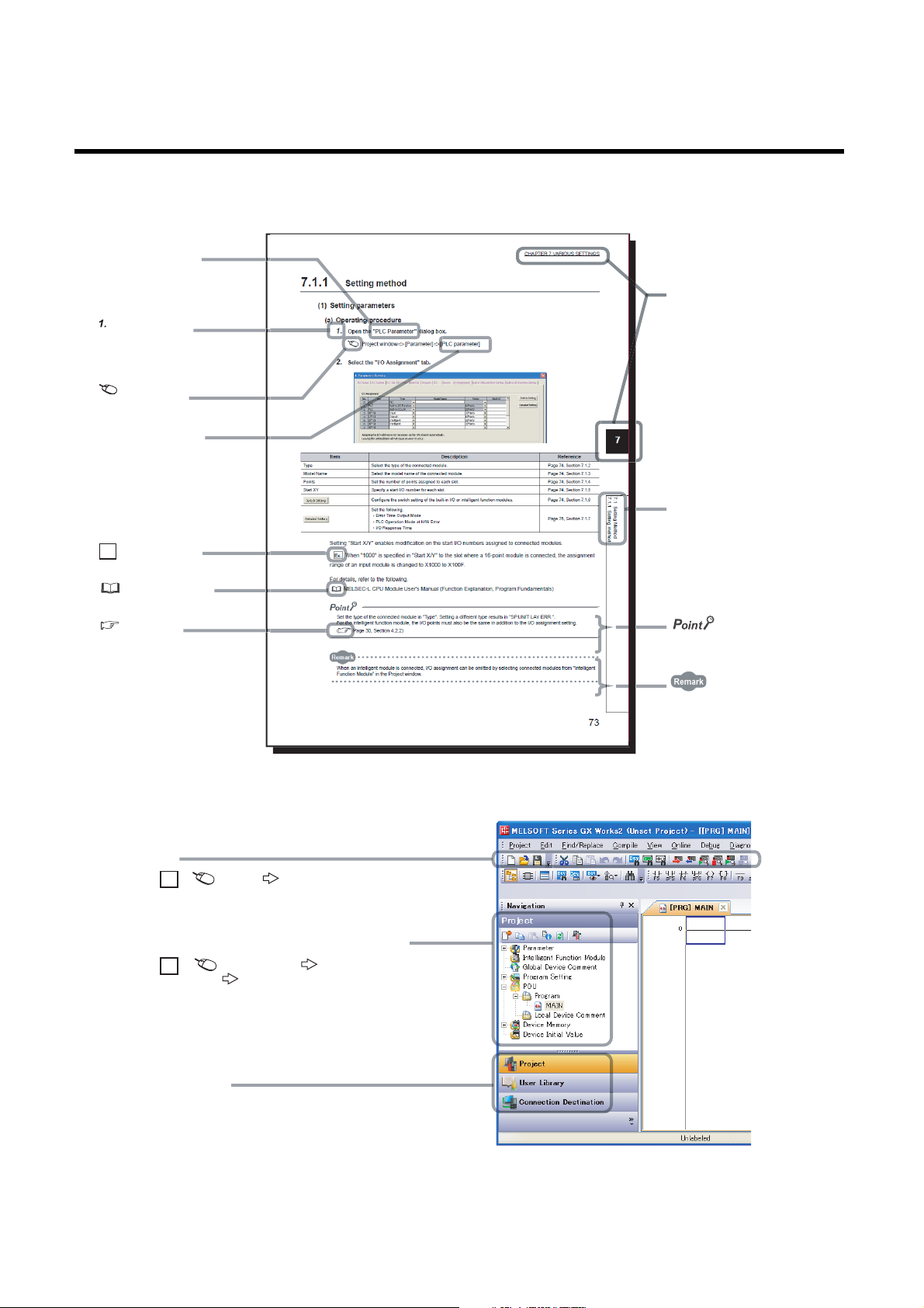
MANUAL PAGE ORGANIZATION
The section of
the current page is shown.
The chapter of
the current page is shown.
"" is used for
screen names and items.
[ ] is used for items
in the menu bar and
the project window.
shows operating
procedures.
shows reference
manuals.
shows notes that
requires attention.
shows mouse
operations.
*1
shows
reference pages.
shows setting or
operating examples.
Ex.
shows useful
information.
A window selected in the view selection area is displayed.
View selection area
[Online] [Write to PLC...]
Select [Online] on the menu bar,
and then select [Write to PLC...].
Project window
[Parameter]
[PLC Parameter]
Select [Project] from the view selection
area to open the Project window.
Menu bar
Ex.
Ex.
In the Project window, expand [Parameter] and
select [PLC Parameter].
In this manual, pages are organized and the symbols are used as shown below.
The following illustration is for explanation purpose only, and should not be referred to as an actual documentation.
*1 The mouse operation example (for GX Works2) is provided below.
14
Page 17
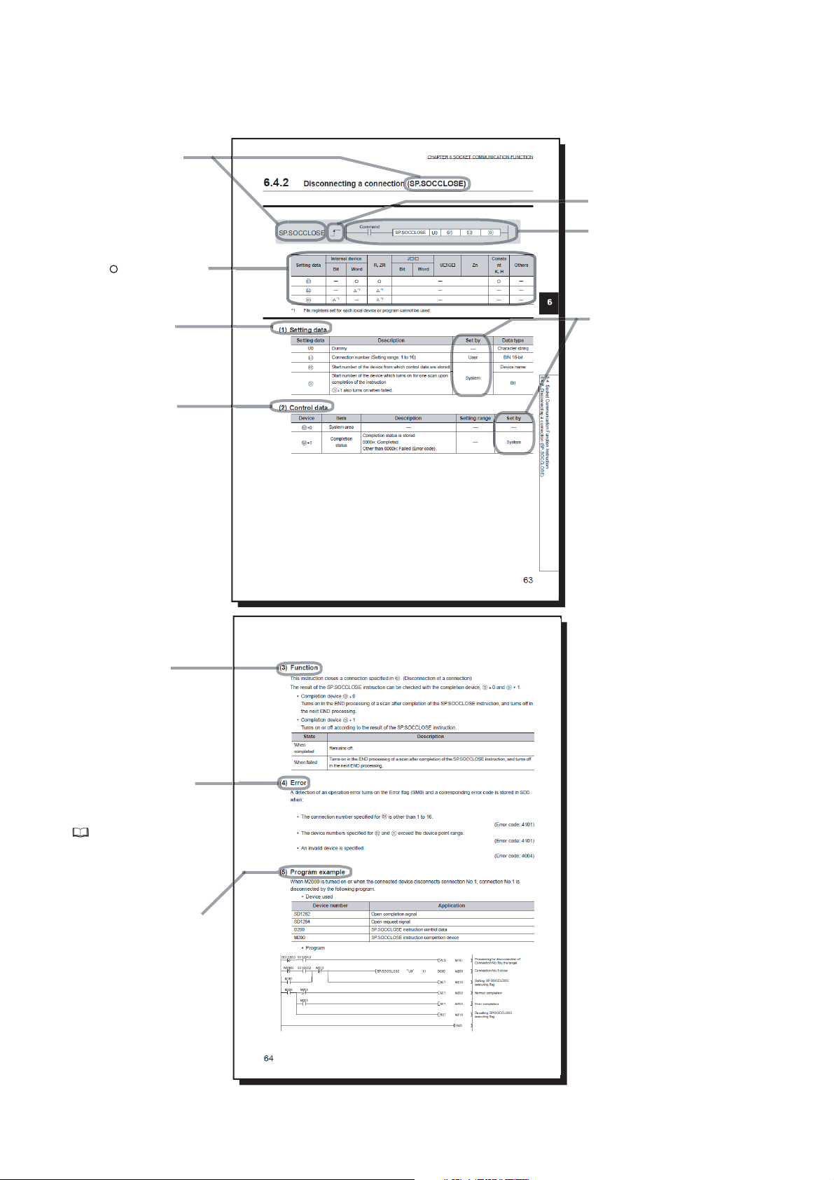
Pages describing instructions are organized as shown below.
Descriptions of
setting data and data type
Instruction name
Structure of the instruction
in the ladder mode
shows the devices
applicable to the instruction
Descriptions of
control data (if any)
Execution condition of the instruction
Setting side
User
: Device value is set by the user
System: Device value is set by
the CPU module.
Conditions for the error and
error codes
For the errors not described in
this manual, refer to the following.
MELSEC-Q/L Programming
Manual (Common Instruction)
Simple program example(s)
and descriptions of the devices used
Detailed descriptions
of the instruction
The following illustration is for explanation purpose only, and should not be referred to as an actual documentation.
15
Page 18

• Instructions can be executed under the following conditions.
Execution condition Any time During on
Symbol No symbol
On the rising
edge
During off
• The following devices can be used.
Link direct
device
J\
Setting
data
Internal device
(system, user)
File
register
Bit Word Bit Word
Applicable
*1
device
X, Y, M,
L, SM, F,
B, SB,
FX, FY
*2
T, ST, C,
D, W,
SD, SW,
FD, @
R, ZR U\G Z K, H, E, $
*1 For details on each device, refer to the following.
MELSEC-L CPU Module User's Manual (Function Explanation, Program Fundamentals)
*2 FX and FY can be used for bit data only, and FD for word data only.
*3 In the "Constant" and "Others" columns, a device(s) that can be set for each instruction is shown.
Intelligent
function module
device
U\G
Index
register
Zn
Constant *3Others
• The following data types can be used.
Data type Description
Bit Bit data or the start number of bit data
BIN 16-bit 16-bit binary data or the start number of word device
BIN 32-bit 32-bit binary data or the start number of double-word device
BCD 4-digit Four-digit binary-coded decimal data
BCD 8-digit Eight-digit binary-coded decimal data
Real number Floating-point data
Character string Character string data
Device name Device name data
On the falling
edge
*3
P, I, J , U, D,
X, DY, N,
BL, TR,
BL\S, V
16
Page 19

TERMS
Unless otherwise specified, this manual uses the following terms.
Ter m Description
Branch module The abbreviation for the MELSEC-L series branch module
Built-in Ethernet port LCPU
CPU module The abbreviation for the MELSEC-L series CPU module
Display unit A liquid crystal display to be attached to the CPU module
END cover A cover to be attached to the right side of the rightmost MELSEC-L series module
Extension cable The abbreviation for the MELSEC-L series extension cable
Extension module The abbreviation for the MELSEC-L series extension module
External device
FTP The abbreviation for File Transfer Protocol, which is a standard network protocol used to exchange files
GX Works2
GX Developer
LCPU Another term for the MELSEC-L series CPU module
MC protocol
Power supply module The abbreviation for the MELSEC-L series power supply module
Programming tool A generic term for GX Works2 and GX Developer
SD memory card
SNTP
A generic term for the L02CPU, L02CPU-P, L06CPU, L06CPU-P, L26CPU, L26CPU-P, L26CPU-BT, and
L26CPU-PBT
A GOT, measuring instrument, ID module, bar code reader, adjuster, and other CPU modules connected
with a CPU module for the data communication
The product name of the software package for the MELSEC programmable controllers
The abbreviation for the MELSEC communication protocol, a protocol to access a CPU module from a target
device in the Ethernet or serial communication
Secure Digital Memory Card, which is a flash memory device.
The NZ1MEM-2GBSD, NZ1MEM-4GBSD, NZ1MEM-8GBSD, NZ1MEM-16GBSD, L1MEM-2GBSD, and
L1MEM-4GBSD are available.
The abbreviation for Simple Network Time Protocol, which is a protocol for synchronizing the clocks of
computer systems over a TCP/IP based network
17
Page 20

CHAPTER 1 OVERVIEW
The following describes the built-in Ethernet function of the CPU module.
(1) Connection with programming tool and GOT ( Page 22, CHAPTER 3)
• By using a hub, the CPU module can be connected to multiple programming tools and GOTs. Up to 16
external devices can be connected to a single CPU module at the same time.
• When CPU modules and a programming tool are connected to the same hub, these CPU modules can be
searched from the programming tool. Displayed search results include IP addresses so that any of them can
be specified.
• MELSOFT connection allows access through routers in an environment such as a corporate LAN.
(2) Direct connection to programming tool (simple connection) ( Page 31,
CHAPTER 4)
The CPU module can be directly connected to a programming tool with a single Ethernet cable only, without
using a hub (simple connection).
For direct connection, the IP address and host name need not be specified in the transfer setup.
(3) MC protocol communication ( Page 34, CHAPTER 5)
From an external device such as a personal computer or HMI, device data of the CPU module can be read or
written using MC protocol commands.
In addition, MC protocol messages (QnA-compatible 3E frame) can be sent from the CPU module to external
devices connected on the Ethernet network.
(4) Communications using the predefined protocol ( Page 53, CHAPTER 6)
The predefined protocol function sends and receives packets predefined by using GX Works2, enabling easy
communications with external devices (such as measuring instruments and bar code readers). Protocol can be
either selected from the prepared predefined protocol library, or created and edited by users.
(5) Socket communication function ( Page 64, CHAPTER 7)
By using instructions dedicated to socket communication, any data can be transferred from and to the external
devices connected through Ethernet using TCP or UDP.
(6) Time setting function (SNTP client) ( Page 116, CHAPTER 8)
• Automatic time setting of the CPU module can reduce the maintenance cost for time setting.
• By sharing the same clock data among CPU modules connected to Ethernet via their built-in Ethernet ports,
the order of errors between processes can be traced, facilitating problem solving.
• Since the automatic time setting is enabled upon power-on of the CPU module, operations can be started
based on accurate clock data.
(7) File transfer function (FTP server) ( Page 119, CHAPTER 9)
Each of the files stored in the CPU module can be read or written from the interfacing device with the FTP client
function, and a large amount of data can be easily transferred.
18
Page 21

CHAPTER 1 OVERVIEW
(8) File transfer function (FTP client) ( Page 139, CHAPTER 10)
Each of the files stored in the CPU module can be read or written from the interfacing device with the FTP server
function, and a large amount of data can be easily transferred.
(9) Remote password ( Page 159, CHAPTER 11)
Remote password setting can prevent unauthorized access from the outside and enhance the security of the
system.
(10)Simple PLC communication function ( Page 165, CHAPTER 12)
Device data can be communicated between the CPU modules connected with Ethernet cable without
programming.
(11)IP packet transfer function ( Page 191, CHAPTER 14)
Communications can be performed with a device which supports the following IP addresses, which have been
specified via a CC-Link IE Field Network module, using a protocol such as the FTP or HTTP via a built-in
Ethernet port from an Ethernet device such as a personal computer.
• External devices on CC-Link IE Field Network
• External devices on the Ethernet network, which are connected through the built-in Ethernet ports
(12)E-mail send/receive function ( Page 193, CHAPTER 15)
E-mail can be sent and received between the CPU module and electronic devices such as mobile phones and
personal computers.
In addition, writing an MC protocol command in the message body of incoming mail enables device reading and
writing.
1
19
Page 22

CHAPTER 2 COMMUNICATION SPECIFICATIONS
The following are the communication specifications of the built-in Ethernet port of the CPU module.
Item Specifications
Data transfer speed 100/10Mbps
Communication mode Full-duplex or half-duplex
Transmission method Base band
Transmission
specifications
Number of
connections
Connection
*1
cable
Maximum distance between hub and
node
Maximum
number of
nodes/connection
TCP/IP A total of 16 connections of socket communications, MELSOFT connection,
UDP/IP
10BASE-T
100BASE-TX Ethernet cable of category 5 or higher (STP cable)
*1 Straight cables can be used. When the CPU module is directly connected to GOT with the Ethernet cable, a cross cable
of Category 5e or lower can also be used.
*2 This number applies when a repeater hub is used. When using a switching hub, check the number of cascaded stages
with the manufacturer of the hub to be used.
*3 Use of STP cables is recommended in an environment with noise.
*4 One setting of FTP client or e-mail uses two consecutive connections.
10BASE-T
100BASE-TX
Cascade connection: Up to four
Cascade connection: Up to two
MC protocol, predefined protocol, FTP client, and e-mail
1 connection for FTP server
Ethernet cable of category 3 or higher (STP/UTP cable)
100m
*2
*2
*4
*3
Hubs with 10BASE-T or 100BASE-TX ports*5 can be used.
Up to 16 external devices can access one CPU module at the same time.
*5 The ports must comply with the IEEE802.3 10BASE-T or IEEE802.3 100BASE-TX standards.
● When connected to a hub, the CPU module determines the cable used (10BASE-T or 100BASE-TX) and the
communication mode (full-duplex or half-duplex) according to the hub. Set the hub into the half-duplex mode if the hub
that does not have the auto-negotiation function.
● The operation of commercial devices used for the following applications is not guaranteed. Check the operation before
using the module.
• Internet (general public line) (Internet-access service offered by an Internet service provider or a
telecommunications carrier)
• Firewall device(s)
• Broadband router(s)
• Wireless LAN
● If Ethernet communication is performed with "Specify service process execution counts" selected for "Service processing
setting" in the PLC system tab of PLC parameter, a scan time increases by time for service processing. (approximately
500ms)
To reduce it to 500ms or less, select an item other than "Specify service process execution counts".
(Example: Select "Specify service process time" and then enter a time value.)
● If broadcast storm occurs in the network, scan time may be increased.
● If the destination device of the CPU module does not respond due to power-off or other reasons, Ethernet communication
of the CPU module may delay up to 500ms.
20
Page 23

CHAPTER 2 COMMUNICATION SPECIFICATIONS
Remark
TCP and UDP are defined as follows:
● TCP (Transmission Control Protocol)
In communications among programmable controllers and networked devices, this protocol establishes a connection
between port numbers of the two devices to perform reliable data communications.
● UDP (User Datagram Protocol)
This is a connectionless protocol and thereby its speed is faster than that of TCP. However, the reliability in data
communications is low. (Data may be lost or not be received in correct order.) Note that simultaneous broadcast is
available.
Select an appropriate protocol, considering the specifications of the external device and the characteristics of the above
protocols.
2
21
Page 24
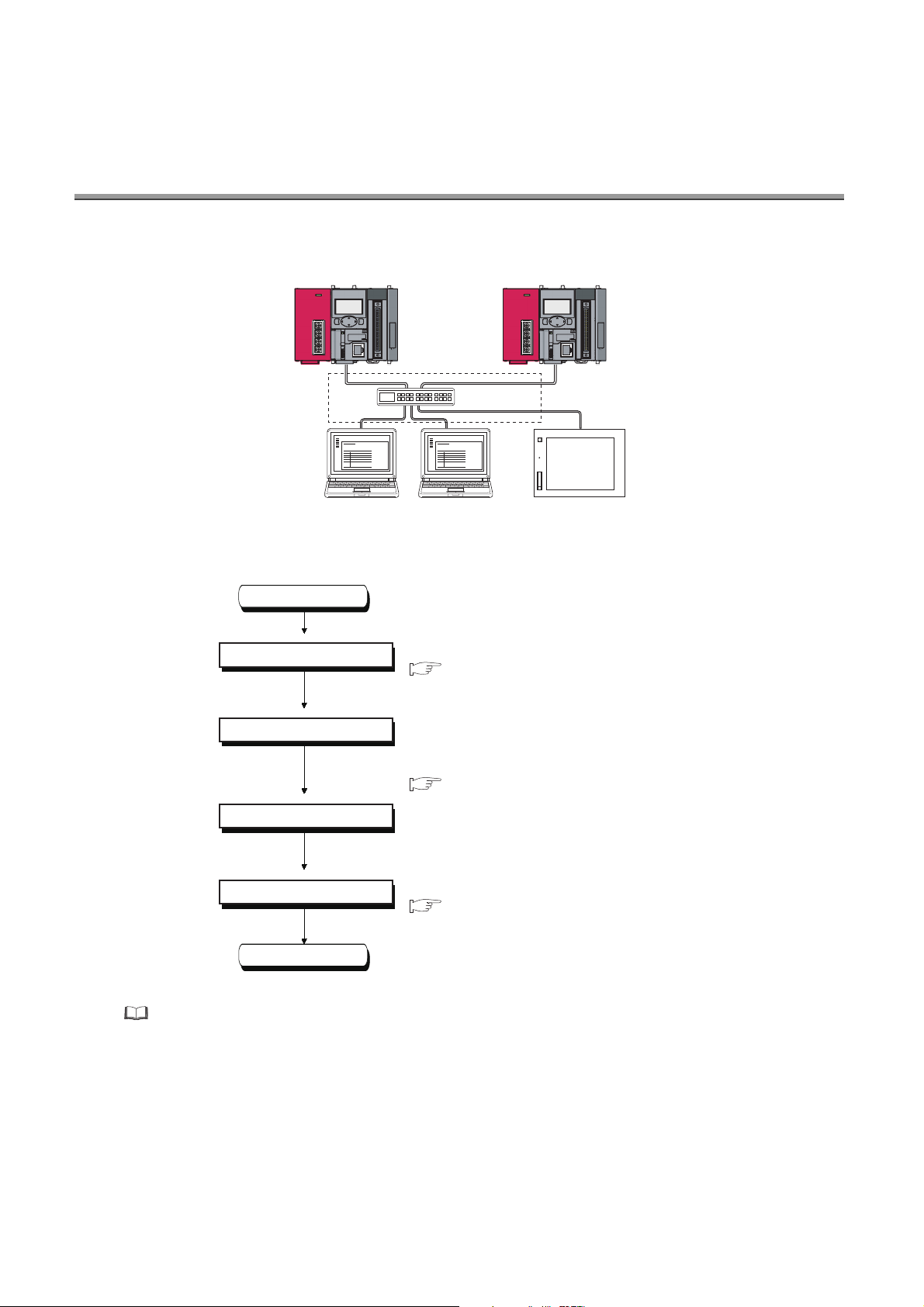
CHAPTER 3 CONNECTION WITH PROGRAMMING
Programming
tool
Programming
tool
GOT
Hub
Ethernet
CPU module CPU module
Start
Setting parameters
Writing to the CPU module
Connecting cables and external
devices
Setting the connection target
End
TOOL AND GOT
This chapter describes how to connect the CPU module to a programming tool or GOT.
To start Ethernet communication, perform the following steps.
For the GOT setting, refer to the following.
Manual for the GOT used
Set PLC parameters using the programming tool.
( Page 23, Section 3.1 (1))
Write the set parameters to the CPU module. Power off
and on or reset the CPU module to enable the
parameters.
( Page 24, Section 3.1 (2))
Connect cables and devices required for Ethernet
communication.
Set a connection target by the programming tool.
( Page 25, Section 3.2)
22
Page 25
CHAPTER 3 CONNECTION WITH PROGRAMMING TOOL AND GOT
1.
2.
3.1 Setting Required for the CPU Module
(1) PLC parameter setting
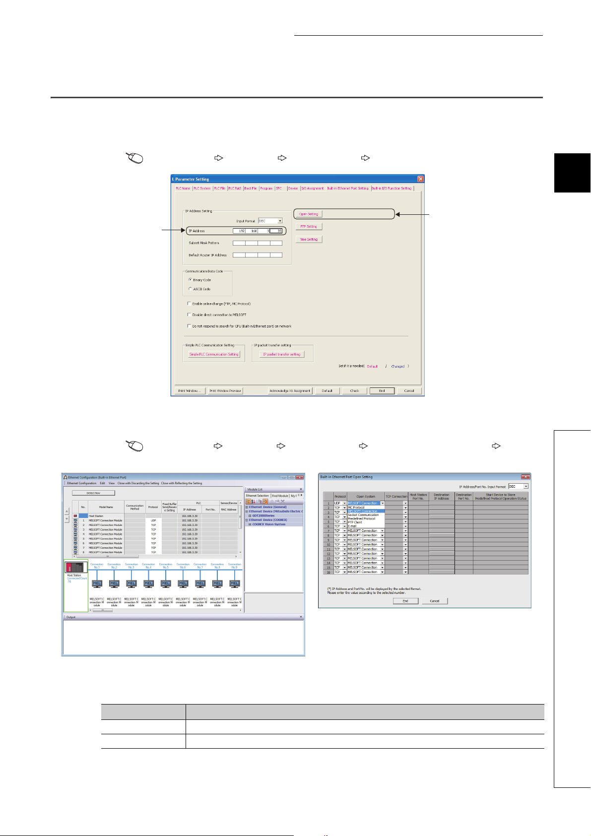
Select the "Built-in Ethernet Port Setting" tab and set the parameters.
Project window [Parameter] [PLC Parameter] [Built-in Ethernet Port Setting]
3
1. Set the IP address of the CPU module.
2. Set MELSOFT connection.
Project window [Parameter] [PLC Parameter] [Built-in Ethernet Port Setting] [Ethernet
Conf.] or [Open Setting] button
• For the "Ethernet Conf.", drag and drop the "MELSOFT Connection Module" from "Module List" to the left
side on the window. Select a protocol from "Protocol" depending on the target device.
• For the "Open Setting"
Item Setting
Protocol Select "TCP" or "UDP" depending on the connected device.
Open System Select "MELSOFT Connection".
3.1 Setting Required for the CPU Module
23
Page 26

(2) Writing parameters to the CPU module
From the "Write to PLC" window, write the parameters to the CPU module.
[Online] [Write to PLC]
After writing the parameters to the CPU module, power off and on or reset the CPU module to enable the
parameters.
24
Page 27
CHAPTER 3 CONNECTION WITH PROGRAMMING TOOL AND GOT
3.2 Setting Required for the Programming Tool
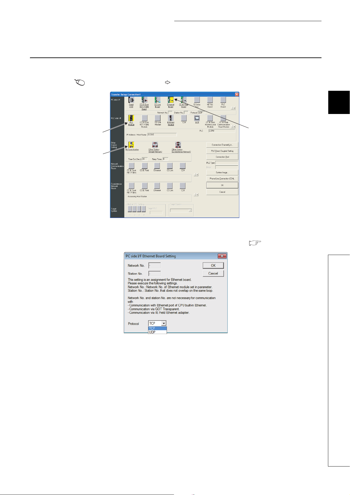
Configure the settings in the "Transfer Setup" window.
Connection Destination window [Connection1]
3
2.
3.
1.
1. Select "Ethernet Board" for "PC side I/F".
In the "PC side IF Ethernet Board Setting" window, select a "TCP" or "UDP" protocol. Select the same
protocol as the one set in the "Ethernet Conf." or "Open Setting" window. ( Page 23, Section 3.1)
3.2 Setting Required for the Programming Tool
25
Page 28
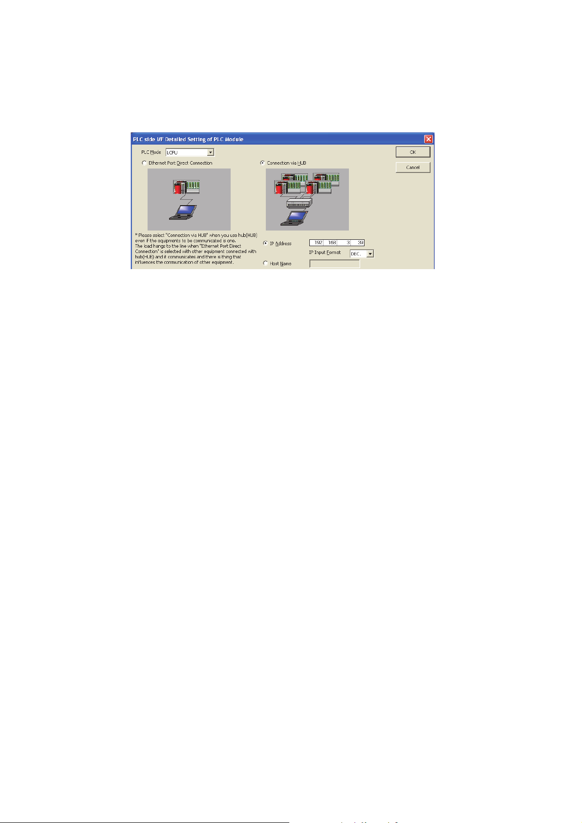
2. Select "PLC Module" for "PLC side I/F".
Enter the IP address or host name of the CPU module in the "PLC side I/F Detailed Setting of PLC
Module" window, as shown below. (For the host name, enter the name set in the Microsoft
hosts file.)
3. Set "Other Station Setting".
Select an item appropriate to the operating environment.
Windows
26
Page 29
CHAPTER 3 CONNECTION WITH PROGRAMMING TOOL AND GOT
Clicking this button will
automatically enter the
IP address of the CPU
module.
3.3 Searching CPU Modules on the Network
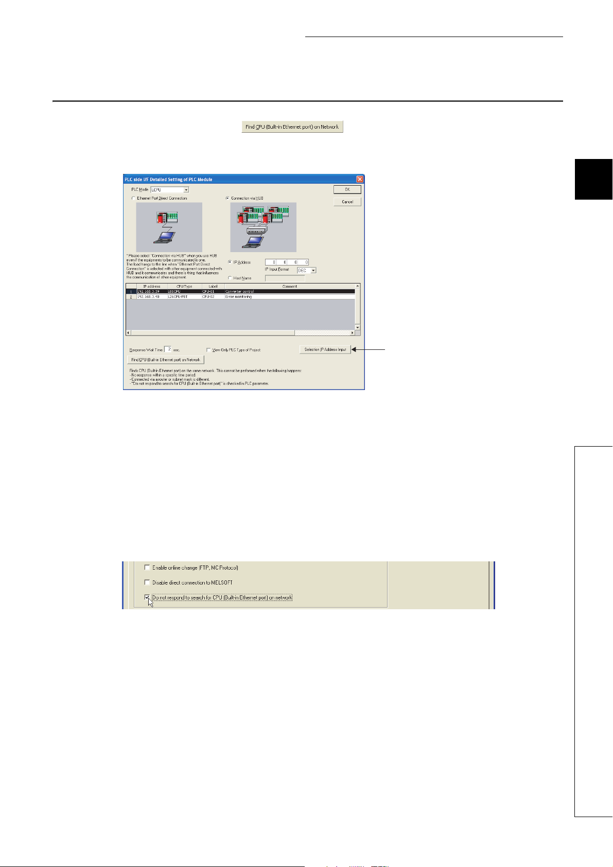
In a configuration using a hub, clicking in the "PLC side I/F Detailed Setting of PLC Module"
window will start searching for CPU modules connected to the hub where the programming tool is also connected, and
display a list of them.
3
• CPU modules connected to cascaded hubs are also searched and a list of them is displayed.
• CPU modules connected via a router cannot be searched.
• Some CPU modules connected via wireless LAN may not be found since Ethernet communication may not
be stable due to packet loss.
• If multiple CPU modules with the same IP address are found in the list, check the IP address parameters for
the CPU modules. Starting communication with the IP address duplicated will cause a communication error.
• Appropriate CPU modules may not be found if a heavy load for service processing is applied. Increase the
response waiting time value in the "Find CPU (Built-in Ethernet port)" window, or the service processing time
value in the Service processing setting tab of PLC parameter.
• By selecting the item shown below in the "Built-in Ethernet Port Setting" tab of PLC parameter, the Find CPU
function can be disabled and the system does not respond to a search request on the network.
3.3 Searching CPU Modules on the Network
27
Page 30
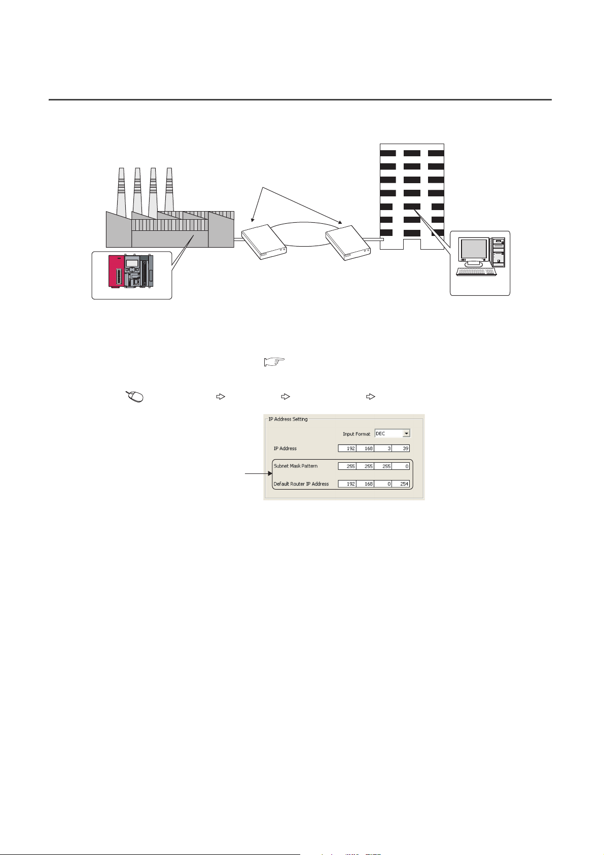
3.4 Communication via Routers
Corporate
LAN
Router
Factory
Control room
Personal
computer
CPU module
From the built-in Ethernet port, access is available via routers on a network such as a corporate LAN.
*1 The following functions do not support the communication via routers.
Searching CPU modules on the network
Simultaneous broadcast in socket communication
For access via a router, follow the instruction ( in the step 1 on Page 23, Section 3.1) to set the subnet mask
pattern and the default router IP address in addition to the IP address.
Project window [Parameter] [PLC Parameter] [Built-in Ethernet Port Setting]
*1
Set the subnet mask pattern
and default router IP address.
28
Page 31

3.5 Precautions
(1) IP address duplication
Check that the IP address is not duplicated when configuring a network or connecting a new device to a network.
If the IP address is duplicated, a device may communicate with the wrong device.
Check for the IP address duplication in the following ways.
• Check for the IP address duplication with the find CPU function.
• Disconnect the device from the line and send ping to the IP address of the disconnected device. Having a
response means the IP address duplication.
(2) KeepAlive check
When the protocol is set to TCP, KeepAlive check is performed. (A response to a KeepAlive ACK message is
checked.) An alive check message is sent five seconds after reception of the last message from the connected
device to check if the device returns a response or not. If no response is received, the alive check message will
be resent at intervals of five seconds. When no response is received for 45 seconds, the connected device is
regarded as non-existent and the connection is disconnected. If the connected device does not support the TCP
KeepAlive function, the connection may be disconnected.
CHAPTER 3 CONNECTION WITH PROGRAMMING TOOL AND GOT
3
(3) Connections exceeding the setting
Do not exceed the number of connections set for "Ethernet Conf." or "Open Setting" of parameters. Establishing
too many TCP connections from a personal computer may cause the following states, depending on the
application.
• Time before timeout error detection is increased.
• An unexpected timeout error occurs in any of the communicating devices.
(4) Retransmission on TCP connection
If no ACK response is returned from the other end of a TCP connection, the ACK will be resent six times, starting
in 0.3 seconds after the first transmission, and then 0.6, 1.2, 2.4, 4.8, and 9.6 seconds. When no TCP ACK
response is returned within 19.2 seconds after the last retransmission, the device is regarded as faulty and the
connection is disconnected. (As a result, the connection is disconnected in total of 38.1 seconds.)
3.5 Precautions
29
Page 32

(5) MELSOFT connection over TCP or UDP
Ethernet
MELSOFT device MELSOFT device
MELSOFT device
Hub
Set the same number
of protocols as that of
MELSOFT devices.
CPU module
For TCP or UDP communications with multiple MELSOFT devices, set the same number of connections as that
of the connected MELSOFT devices in PLC parameter.
When all MELSOFT devices start communicating at the same time, devices may fail to communicate because of the
congestion of communications. In such a case, schedule the timing for when each device starts communicating so that the
communication congestion will not occur. When using GOTs, for example, set different rise time and time-out values in the
GOTs.
(6) Sampling trace
When the function has been executed using the programming tool via a built-in Ethernet port, stop the function
before powering off or resetting the CPU module.
(7) Remote STOP or remote PAUSE
When remote STOP or remote PAUSE has been executed using the programming tool via a built-in Ethernet
port, perform the following operations before powering off or resetting the CPU module.
• Remote RUN
• Remote RESET
30
Page 33

CHAPTER 4 DIRECT CONNECTION TO PROGRAMMING TOOL (SIMPLE CONNECTION)
CHAPTER 4 DIRECT CONNECTION TO
PROGRAMMING TOOL (SIMPLE
CONNECTION)
The CPU module can be directly connected to the programming tool with an Ethernet cable, without using a hub
(simple connection).
For direct connection, the IP address and host name need not be specified in the connection target setting.
(Simultaneous broadcast is used.)
CPU module
4
Ethernet cable
An Ethernet cable used for direct connection will be longer compared with the case of using a USB cable. This can cause an
unauthorized connection from a remote location.
Unauthorized connections can be prevented by selecting the following option in the "Built-in Ethernet port" tab of PLC
parameter.
Programming tool
31
Page 34

4.1 Setting Method
2.
3.
1.
Set the items on the "Transfer Setup" window.
Connection Destination window [Connection1]
1. Select "Ethernet Board" for "PC side I/F".
2. Select "PLC Module" for "PLC side I/F".
In the "PLC side IF Detailed Setting of PLC Module" window, select the Ethernet Port Direct Connection
checkbox as shown below.
3. Complete setting of "Other Station Setting".
Select an item appropriate to the operating environment.
32
Page 35

4.2 Precautions
Remark
Ethernet cable
Programming tool
CPU module
Hub
(1) Connection to LAN line
When connecting the CPU module to a LAN line, do not set direct connection. Doing so will apply a load to the
LAN line and adversely affect communications with other external devices.
(2) Indirect connection
• Do not set up direct connection when a CPU module is connected to an external device in a one-to-one
basis using a hub as shown below.
CHAPTER 4 DIRECT CONNECTION TO PROGRAMMING TOOL (SIMPLE CONNECTION)
4
• When two or more Ethernet ports are enabled in the network connections setting on the personal computer,
communication by direct connection is not possible. In the setting, leave only one Ethernet port enabled for
direct connection and disable other Ethernet ports.
(3) Conditions that disallow direct connection
When any of the following conditions is met, communication by direct connection may not be available. In that
case, check the setting of the CPU module and/or personal computer.
• In the CPU module IP address bits, the bits corresponding to "0" in the personal computer subnet mask are
all on or all off.
Example: CPU module IP address : 64. 64. 255. 255
Personal computer IP address : 64. 64. 1. 1
Personal computer subnet
mask
• In the CPU module IP address bits, the bits corresponding to the host address of the class in the personal
computer IP address are all on or all off.
Example: CPU module IP address : 64. 64. 255. 255
Personal computer IP address : 192. 168. 0. 1
Personal computer subnet
mask
: 255. 255. 0. 0
:255.0.0. 0
4.2 Precautions
● The IP address pattern for each class is as follows.
Class A: 0.x.x.x to 127.x.x.x, Class B: 128.x.x.x to 191.x.x.x, Class C: 192.x.x.x to 223.x.x.x
● The host address for each class is the part shown with "0".
Class A: 255. 0. 0. 0, Class B: 255.255. 0. 0, Class C: 255.255.255. 0
33
Page 36

CHAPTER 5 MC PROTOCOL COMMUNICATION
Connecting cables and external
devices
The built-in Ethernet port allows MC protocol communication.
5.1 Sending a Command from an External Device to the CPU
Module
From an external device such as a personal computer or HMI, device data of the CPU module can be read or written
using MC protocol. Monitoring of CPU module operation, data analysis, and production control are available on a
personal computer or HMI by these device data reading and writing. Besides, the remote password function can
prevent unauthorized access from outside of the system. ( Page 159, CHAPTER 11)
CPU module
Hub
GOT
From the external device such as a personal computer or HMI, only the CPU module connected can communicate using MC
protocol.
An access to a CPU module on another station via CC-Link network is not allowed.
To start MC protocol communication, perform the following steps.
Start
Setting parameters
Writing to the CPU module
Communication using MC protocol
Connect cables and devices required for MC protocol
communication.
Set PLC parameters using the programming tool.
( Page 36, Section 5.1.1)
Write the set parameters to the CPU module. Power
off and on or reset the CPU module to enable the
parameters.
End
For the MC protocol communication, refer to the following manual.
MELSEC Communication Protocol Reference Manual
34
MC protocol communication is available.
Page 37

CHAPTER 5 MC PROTOCOL COMMUNICATION
Remark
Access through routers is also available. When configuring the settings for it, set the subnet mask pattern and default router
IP address. ( Page 28, Section 3.4)
5
5.1 Sending a Command from an External Device to the CPU Module
35
Page 38

5.1.1 Setting Method
Setting for communication using the MC protocol is described below.
Project window [Parameter] [PLC Parameter] [Built-in Ethernet Port Setting]
1.
2.
3.
1. Select Binary or ASCII code as the communication data code used for MC protocol.
2. Select the "Enable online change (FTP, MC Protocol)" checkbox to enable data to be written to the
CPU module even in the RUN state.
36
Page 39

CHAPTER 5 MC PROTOCOL COMMUNICATION
3. Set connections used for MC protocol communication.
Project window [Parameter] [PLC Parameter] [Built-in Ethernet Port Setting] [Ethernet
Conf.] or [Open Setting] button
• For "Ethernet Conf.", drag and drop "SLMP Connection Module" from "Module List" to the left side on the
window. Select a protocol from "Protocol" depending on the target device. Set the port number of the host
station in "Port No.". (Setting range: 1025 to 4999, 5010 to 65534) Do not specify 5000 to 5009 because
these ports are used by the system. ( Page 221, Appendix 2)
5
• For the "Open Setting"
Item Description
Protocol Select TCP or UDP depending on the target device.
Open System Select "MC Protocol".
Host Station Port No.
*1 Do not specify 1388H to 1391H (5000 to 5009) because these ports are used by the system. ( Page 221, Appendix
2)
When the "Enable online change (FTP, MC protocol)" setting is disabled, if the CPU module in the RUN state receives a data
write request from the target device, data will not be written and an NAK message will be returned.
Set the port number of the host station. (Setting range: 0401
(1025 to 4999, 5010 to 65534))
*1
to 1387H, 1392H to FFFEH
H
5.1 Sending a Command from an External Device to the CPU Module
37
Page 40

5.1.2 MC Protocol Commands
(1) Command list
The following commands are executable for MC protocol communication of the CPU module.
Command
(Subcommand)
0401
(0001)
0401
(0000)
1401
(0001)
1401
(0000)
0403
(0000)
1402
(0001)
1402
(0000)
*2
0801
(0000)
0802
(0000)
1630
(0000)
1631
(0000)
*1
Reads bit devices in units of one point.
Reads bit devices in units of 16 points.
Reads word devices in units of one point. 960 points
Writes bit devices in units of one point.
Writes bit devices in units of 16 points.
Writes word devices in units of one point. 960 points
Reads bit devices in units of 16 or 32
points by randomly specifying the target.
Reads word devices in units of one or two
points by randomly specifying the target.
Sets or resets bit devices in units of one
point by randomly specifying the target.
Sets or resets bit devices in units of 16 or
32 points by randomly specifying the
target.
Writes word devices in units of one or two
points by randomly specifying the target.
Registers bit devices to be monitored in
units of 16 or 32 points.
Registers word devices to be monitored
in units of one or two points.
Monitors the devices registered.
Specifies a remote password to unlock
the locked state.
Specifies a remote password to lock the
unlocked state.
Device
memory
Remote
password
Function
Batch read
Batch write
Random read
Test (Random
write)
Monitor
registration
Monitor
Unlock
Lock
*2*3*4
*2
In units
of bits
In units
of
words
In units
of bits
In units
of
words
In units
of
words
In units
of bits
In units
of
words
In units
of
words
In units
of
words
Description
: Available, : N/A
CPU module status
Number of
processed
points
ASCII: 3584
points
BIN: 7168
points
960 words
(15360
points)
ASCII: 3584
points
BIN: 7168
points
960 words
(15360
points)
192 points
188 points
*5
192 points
Number of
registered
points
STOP
Write
enabled
RUN
Write
disabled
38
*1 These commands are for QnA-compatible 3E frames.
*2 Devices, TS, TC, SS, SC, CS, and CC cannot be specified in units of words. Specifying any of these for monitor
registration will cause an error (4032
) at the time of monitoring execution.
H
*3 For monitor registration, monitoring conditions cannot be set.
*4 Do not execute monitor registration from multiple devices. If executed, the last monitor registration takes effect.
*5 Set the number of processed points so that the following condition is satisfied.
(Number of word access points) 12 + (Number of double-word access points) 14 1920
For bit devices, one point is regarded as 16 bits in word access and 32 bits in double-word access. For word devices,
one point is regarded as one word in word access, and two words in double-word access.
Page 41

(2) Applicable devices
The following table lists the devices applicable in the commands used for MC protocol communication.
Classification Device
Input X*
Output Y*
Internal relay M*
Latch relay L*
Annunciator F*
Edge relay V*
Link relay B*
Data register D*
Link register W*
Contact TS
Timer
Internal user device
Retentive
timer
Counter
Link special relay SB
Link special register SW
Step re lay S *
Direct input
Direct output
Function input
Function output Hexadecimal
Internal system device
Function register Decimal
Special relay SM
Special register SD
Index register Z*
File register
Extended data register D*
Extended link register W*
Current value TN
Contact SS
Current value SN
Contact CS
Current value CN
*2
*2
DX
DY
R*
ZR
Device code
*1
ASCII Binary
9C
H
9D
H
90
H
92
H
93
H
94
H
A0
H
A8
H
B4
H
C1
H
C0
H
C2
H
C7
H
C6
H
C8
H
C4
H
C3
H
C5
H
A1
H
B5
H
98
H
A2
H
A3
H
91
H
A9
H
CC
H
AF
H
B0
H
A8
H
B4
H
CHAPTER 5 MC PROTOCOL COMMUNICATION
Device number range
The number range of a device in a CPU module, which
is accessed to, can be specified.
The number range of a device in a CPU module, which
is accessed to, can be specified. Note that the access
to a local device is not possible.
The number range of a device in a CPU module, which
is accessed to, can be specified.
Cannot be accessed.
The number range of a device in a CPU module, which
is accessed to, can be specified.
The number range of a device in a CPU module, which
is accessed to, can be specified. Note that the access
to a local device is not possible.
The number range of a device in a CPU module, which
is accessed to, can be specified.
Hexadecimal
Hexadecimal
Decimal
Decimal
Decimal
Decimal
Hexadecimal
Decimal
Hexadecimal
DecimalCoil TC
DecimalCoil SC
DecimalCoil CC
Hexadecimal
Hexadecimal
Decimal
Hexadecimal
Hexadecimal
Hexadecimal
Decimal
Decimal
Decimal
Decimal
Decimal
Decimal
Hexadecimal
5
5.1 Sending a Command from an External Device to the CPU Module
*1 This is a code specified in MC protocol messages. When communicating data in ASCII code, specify the code in two
characters. If the code consists of only one character, add "*" (ASCII code: 2A
) or a space (ASCII code: 20H) after the
H
character.
*2 For the L02CPU and L02CPU-P, devices of DX/DY400 or later number cannot be used. Use X/Y devices to access
devices of X/Y400 or later. For the L06CPU, L06CPU-P, L26CPU, L26CPU-P, L26CPU-BT, and L26CPU-PBT, devices
of DX/DY1000 or later number cannot be used. Use X/Y devices to access devices of X/Y1000 or later.
39
Page 42

5.1.3 Precautions
(1) Number of devices
Only the external devices set in "Ethernet Conf." or "Open Setting" can be connected concurrently using MC
protocol.
Project window [Parameter] [PLC Parameter] [Built-in Ethernet Port Setting] [Ethernet
Conf.] or [Open Setting] button
(2) Data communication frame
The QnA-compatible 3E frames only are applicable to CPU modules.
(3) Access range
• Only the connected CPU module can be accessed. Accessing another module will cause an error.
• Accessing another station on a network such as CC-Link is not allowed via the connected CPU module.
(4) When UDP is selected for Protocol
• If a new request message is sent to a UDP port after the previous request message is sent to the same port
and before no response is returned, the new request message will be discarded.
• Setting the same host station port number for multiple UDP connections is regarded as one setting. For
communication with multiple devices using the same host station port number, select TCP.
(5) File access during MC communication
The CPU module will perform file access processing prior to Ethernet communication processing. Because of
this, processing of the MC protocol function may be delayed if a file is accessed by FTP or a programming tool
during use of the MC protocol function.
When accessing a file while response time monitoring is performed on the connected device with the MC protocol
function, add the time required for file access to the monitoring time.
40
Page 43

(6) Receiving a response message
The following shows an example of receive processing on the other device side.
Communication processing on the other device side
Request message, send processing
Response message, receive processing
CHAPTER 5 MC PROTOCOL COMMUNICATION
Is TCP connection open?
YES
Received data
within the time specified by
the monitoring timer
value?
YES
Check the received data size.
NO
Sufficient receive
data size?
YES
Processing for the response message
Was the entire
received message
processed?
YES
End Error handling
NO
NO
NO
For Ethernet communication, TCP socket functions are used inside personal computers.
The functions do not have boundary concept. Therefore, if the sender sent data by calling the "send" function once, the
receiver needs to call the "recv" function once or more times to read out the data. ("send" does not correspond to "recv" on
the one-to-one basis.)
For this reason, the processing shown above is always required on the program of the receiving device.
Note that, if the "recv" function is used in blocking mode, data may be read by calling the function once.
5
5.1 Sending a Command from an External Device to the CPU Module
41
Page 44

5.1.4 Error Codes for MC Protocol Communication
When an error occurs during MC protocol communication, an error code is sent from the CPU module to the external
device. The following table lists error codes, error descriptions, and actions to be taken.
Error code
(Hexadecimal)
4000H to 4FFF
0055
H
C050
H
C051
to C054
H
C056
H
C058
H
C059
H
C05B
H
C05C
H
C05D
H
C05F
H
C060
H
C061
H
C06F
H
C070
H
C0B5
H
C200
H
C201
H
C204
H
Errors detected by the CPU module
H
(Errors occurred in other than MC protocol communication)
Although online change is disabled, the connected device
requested the RUN-state CPU module for data writing.
When "Communication Data Code" is set to ASCII Code, ASCII
code data that cannot be converted to binary were received.
The number of read or write points is outside the allowable range.
H
The read or write request exceeds the maximum address.
The request data length after ASCII-to-binary conversion does not
match the data size of the character area (a part of text data).
• The command and/or subcommand are specified incorrectly.
• The CPU module does not support the command and/or
subcommand.
The CPU module cannot read data from or write data to the
specified device.
The request data is incorrect. (e.g. reading or writing data in units of
bits from or to a word device)
No monitor registration Perform monitor registration before monitoring.
The request cannot be executed to the CPU module.
The request data is incorrect. (ex. incorrect specification of data for
bit devices)
The request data length does not match the number of data in the
character area (a part of text data).
The CPU module received a request message in ASCII format
when "Communication Data Code" is set to Binary Code, or
received it in binary format when the setting is set to ASCII Code.
(This error code is only registered to the error history, and no
abnormal response is returned.)
The device memory extension cannot be specified for the target
station.
The CPU module cannot handle the data specified.
The remote password is incorrect.
The port used for communication is locked with the remote
password. Or, because of the remote password lock status with
"Communication Data Code" set to ASCII Code, the subcommand
and later part cannot be converted to a binary code.
The connected device is different from the one that requested for
unlock processing of the remote password.
Description Action
Refer to the following.
MELSEC-L CPU Module User's Manual (Hardware Design,
Maintenance and Inspection)
• Before enabling online change, write the data.
• Change the operating status of the CPU module to STOP and
write the data.
• Select Binary Code for "Communication Data Code", and restart
the CPU module.
• Correct the send data of the connected device and resend the
data.
Correct the number of read or write points, and resend the data to
the CPU module.
Correct the start address or the number of read or write points, and
resend the data to the CPU module. (The maximum address must
not be exceeded.)
Check and correct the text data or the request data length of the
header, and resend the data to the CPU module.
• Check the request.
• Use commands and/or subcommands supported by the CPU
module.
Check the device to be read or written.
Correct the request data and resend it to the CPU module. (e.g.
subcommand correction)
• Correct the network number, PC number, request destination
module I/O number, or request destination module station
number.
• Correct the read/write request data.
Correct the request data and resend it to the CPU module.
Check and correct the text data or the request data length of the
header, and resend the data to the CPU module.
• Send a request message that matches the "Communication Data
Code" setting.
• Change the "Communication Data Code" setting so that it will
match the request message.
Read data from or write data to the device memory without
specifying the extension.
• Correct the request data.
• Stop the current request.
Correct the remote password, and unlock and lock the remote
password function again.
Unlock the remote password before communication.
From the device that requested the unlock processing, request for
lock processing of the remote password.
42
Page 45

CHAPTER 5 MC PROTOCOL COMMUNICATION
Remark
5.2 Sending a Command from the CPU Module to an
External Device
MC protocol messages (QnA-compatible 3E frame) can be sent from the CPU module to external devices on the
Ethernet network.
To send the messages, use the SLMP frame send instruction.
External device
CPU module
Request message
Ethernet
Before sending the messages from the CPU module to external devices by using the SLMP frame send instruction, check
the version of the CPU module used. ( Page 222, Appendix 3)
Header Subheader CommandAccess destination
Header Subheader Response data
Response message
5
5.2 Sending a Command from the CPU Module to an External Device
43
Page 46

5.2.1 Sending an SLMP frame (SP.SLMPSND)
SP.SLMPSND
SP.SLMPSND
"U0"
S1 S2 D1 D2
Command
S2
D2
D1
D2
Setting data
S1
D1
Internal device
Bit Word Bit Word
*1 Local devices cannot be used.
(1) Setting data
Setting data Description
U0 Dummy
S1
S2
Start number of the device from which control data are stored User, system Device name
Start number of the device from which a request frame is
stored
Start number of the device from which a response frame is
stored
Start number of the device which turns on for one scan upon
completion of the instruction
D2
error.
R, ZR
*1
*1
*1
J\
U\G Zn
Set by
Constant
*1
K, H
Data type
Character string
Others
User Device name
System Device name
System Bit
+1 also turns on when the instruction is completed with an
44
*1 The "Set by" column indicates the following.
User: The data must be set before the SP.SLMPSND instruction is executed.
System: The CPU module stores the execution result of the SP.SLMPSND instruction.
Page 47

CHAPTER 5 MC PROTOCOL COMMUNICATION
S1
S1
S1
S1
S1
S1
S1
S1
S1
S1
b15 b7b8 b0
12
S1S1S1
S1
(2) Control data
Device Item Description Setting range
b15 b7 b0
10 0[2] [1]
[1] Execution type
• 0: Without arrival check (The instruction is regarded as completed
*2
User
System
00000001
FFFFFFFE
to
H
H
(both +3 and
+4 together)
(1 to
4294967294)
1 to 65534
(1 to FFFE
0000
00FF
03FF
H
03E3
H
03D3
)
H
H
H
, 03E0H to
, 03D0H to
H
+0
+1
+2
+3
+4
+5
+6
+7
+8
Execution/error
completion type
Completion
status
Host station
channel No.
IP address of
external device
(third and fourth
octets)
IP address of
external device
(first and second
octets)
Target device
port number
Request
destination
network number
Request
destination
station number
Request
destination
module I/O
number
when a request message is sent from the host station.)
• 1: With arrival check (The instruction is regarded as completed
when a response message is received from the external device.)
[2] Error completion type
Specify whether to set data at completion with an error.
• 0: Do not set data in +13 and later at completion with an
S1
error. (Clear +13 or later.)
• 1: Set data in +13 or later at completion with an error.
The completion status is stored.
0000
: Completed normally
H
Other than 0000
: Completed with an error (error code)
H
Fixed to 1 1 User
Specify the IP address (third and fourth octets) of external device.
b15 b7b8 b0
34
3, 4: Indicates the octets of the IP address.
Specify the IP address (first and second octets) of external device.
1, 2: Indicates the octets of the IP address.
Specify the port number of the target device.
Fixed to 0000
Fixed to 00FF
H
H
Specify an access target module.
• 03FF
: Host station/control CPU
H
: Multiple CPU No.1
• 03E0
H
: Multiple CPU No.2
• 03E1
H
: Multiple CPU No.3
• 03E2
H
• 03E3
: Multiple CPU No.4
H
: Control system CPU
• 03D0
H
: Standby system CPU
• 03D1
H
: System A CPU
• 03D2
H
• 03D3
: System B CPU
H
*1
Set by
5
User
5.2 Sending a Command from the CPU Module to an External Device
User
User
User
User
User
45
Page 48

Device Item Description Setting range
S1
S1
S1
S1
S1
S1
S1
S1
S1
S1
S1
S1
b15 b7b8 b0
12
S1
Request
destination
+9
multidrop station
number
+10
+11
+12
Number of
resends
Arrival monitoring
time
Clock setting flag
+13
+14
Clock data
+15
+16
IP address of
+17
error detected
device (third and
fourth octets)
IP address of
+18
error detected
device (first and
second octets)
*1 The "Set by" column indicates the following.
User: The data must be set before the SP.SLMPSND instruction is executed.
System: The CPU module stores the execution result of the SP.SLMPSND instruction.
*2 If +0 is set to "0: Without arrival check", receive data is not set. Set 0 in +0 in the following cases:
When a command that does not return a response message is used
When a response message is not referred to
Fixed to 0000
H
The device becomes effective when the execution type specified by
S1
+0 is "1: With arrival check".
■Before instruction execution
Specify the number of resends to be performed if the instruction is
not completed within the monitoring time specified by +11.
S1
• Setting range: 0 to 15
■At completion of instruction
The number of resends performed (result) is stored.
• Setting range: 0 to 15
Specify the monitoring time until completion of processing. If
processing is not completed within the monitoring time, the request
is resent for the number of resends specified in +10.
0: 10 seconds
1 to 32767: 1 to 32767 seconds
The validity status (valid or invalid) of the data in +13 and later is
stored. The data in +13 and later is cleared when the instruction
S1
is completed successfully.
0: Invalid
1: Valid
Upper 8 bits: Month (01
Lower 8 bits: Last two digits of the year (00
Upper 8 bits: Hour (00
Lower 8 bits: Day (01
Upper 8 bits: Second (00
Lower 8 bits: Minute (00
Upper 8 bits: First two digits of the year (00
Lower 8 bits: Day of the week (00
to 12H)
H
to 23H)
H
to 31H)
H
H
to 59H)
H
to 59H)
to 99H)
H
to 99H)
H
(Sun) to 06H (Sat))
H
The IP address (third and fourth octets) of the device where an error
was detected is stored.
b15 b7b8 b0
34
3, 4: Indicates the octets of the IP address.
The IP address (first and second octets) of the device where an
error was detected is stored.
1, 2: Indicates the octets of the IP address.
S1
0000
H
0 to 15 User/system
0 to 32767 User
System
System
System
Set by
User
*1
46
Page 49

CHAPTER 5 MC PROTOCOL COMMUNICATION
S2
S2
S2
S2
D1
(3) Request frame
Device Item Description Setting range
+0
+1
Request data
length
Monitoring timer
Specify the data length from the monitoring timer to the request
data. (In units of bytes)
This timer sets the waiting time for the external device that received
a request message to wait for the response after it issued a
processing request to the access destination. (Unit: Increments of
250ms)
0: Infinite wait
1 to 65535: 1 to 65535 250ms
1 to 2000 User
0 to 65535 User
Set by
*1
+2 to
+n
Request data The request data of the MC protocol message is stored. User
*1 The "Set by" column indicates the following.
User: The data must be set before the SP.SLMPSND instruction is executed.
(4) Response frame
Device Item Description Setting range
D1
D1
+2 to
D1
+0
+1
+n
Response data
length
End code
Response data
*1 The "Set by" column indicates the following.
System: The CPU module stores the execution result of the SP.SLMPSND instruction.
The data length from the end code to the response data is stored.
(In units of bytes)
The result of command processing is stored.
In normal end, 0 is stored. In abnormal end, an error code set by the
external device is stored.
Execution results for the request data are set.
(Some commands do not return response data.)
2 to 2000 System
System
System
Set by
5
*1
5.2 Sending a Command from the CPU Module to an External Device
47
Page 50

(5) Function
Request
destination
module I/O No.
Header FooterSubheader
Request
destination
station No.
Request
destination
network
No.
Request
destination
multidrop
station No.
Request data
length
Monitoring timer Request data
Specified by (except some devices) Specified by
+8+3 to +5 +7 +6 +9 +0 +1 +2 to +n
S1 S1 S1
S1
S1 S1 S1
S2S2 S2
S2
S2
Request
destination
module I/O No.
Header Subheader
Request
destination
station No.
Request
destination
network
No.
Request
destination
multidrop
station No.
Response data
length
End code Response data Footer
Stored in
+0 +2 to +n
D1
+1
D1 D1
D1
D1
• This instruction sends the request frame in the device specified by and later to the external device
S2
specified by the external device IP address in the control data. When a response message is received from
the external device, it is stored in the device specified by .
D1
The following figures show the request data and the response data in normal/abnormal end.
Request data
Response data
When completed normally
When completed with an error
Header Subheader
• The SP.SLMPSND instruction communicates using UDP. Set the external device to use UDP.
• The SP.SLMPSND instruction communicates in binary code. Match the setting of the external device also
with the binary code.
• When the setting is configured in "Simple PLC Communication Setting" of the PLC parameter, the
SP.SLMPSND instruction cannot be executed.
Request
Request
destination
destination
station No.
network
No.
Response data
length
D1 D1
+0
Request
destination
module I/O No.
+1
Request
destination
multidrop
station No.
Network No.
(responding
station)
Station No.
(responding
station)
Stored in
Request
destination
module I/O No.
D1
Request
destination
multidrop
station No.
Error information
Command SubcommandEnd code
Footer
48
Page 51

CHAPTER 5 MC PROTOCOL COMMUNICATION
Ex.
34H12H02H00HEFH1D
H
12
H
00
H
1D
H
34
H
02
H
EF
H
b8b7 b0
......
b15
+2
+3
+4
D1
D1
D1
D100 D101 D102
• The result of the SP.SLMPSND instruction can be checked with the completion device, +0 and +1.
• Completion device +0
D2
D2 D2
This device turns on at the END processing of the scan in which the SP.SLMPSND instruction is completed and turns off at
the next END processing.
• Completion device +1
D2
This device turns on or off according to the result of the SP.SLMPSND instruction.
State Description
When completed
normally
When completed
with an error
Remains off.
Turns on at the END processing of scan in which the SP.SLMPSND instruction is completed and turns off
at the next END processing.
When the instruction is completed with an error, an error code is stored in the completion status of +1.
S1
Sending "Batch read in word units (command: 0401H)" which reads the value in D100 to D102
Request data
Command
01H04H00H00H64H00H00HA8H03H00
......
b8b7 b0
b15
S2
+2
04
01
H
H
+3
00
00
A8
00
00
H
H
64
H
H
00
H
H
03
H
H
S2
+4
S2
+5
S2
+6
S2
Subcommand
Start device No.
Device
code
Number of
device points
H
5
5.2 Sending a Command from the CPU Module to an External Device
Response data
49
Page 52

(6) Error
S1
S2S1S2
D1
D2
S1
Each of the following events results in an operation error, and the error flag (SM0) turns on and an error code is
stored in SD0.
• An instruction is used in a CPU module with a serial number (first five digits) of "18111" or earlier.
(Error code: 4002)
• The value specified by +2 as the host station channel number is outside the specified range.
(Error code: 4101)
• The value specified by +0 as the request data length is out of the range of 1 to 2000.
(Error code: 4100)
• The device specified by , , , or exceeds the range of the number of device points.
(Error code: 4101)
• A device which cannot be specified is specified.
(Error code: 4004)
• An instruction has been executed when the simple PLC communication is set in the PLC parameter.
(Error code: 4161)
When the instruction completes with an error, the completion status indication device +1 turns on and an error
code is stored in the completion status +1. For the error code stored in the completion status +1, refer to the
S1
following.
MELSEC-L CPU Module User's Manual (Hardware Design, Maintenance and Inspection)
D2
50
Page 53

CHAPTER 5 MC PROTOCOL COMMUNICATION
(7) Precautions
• Do not execute multiple SP.SLMPSND instructions concurrently. Multiple SP.SLMPSND instructions
specifying the same channel cannot be used concurrently.
• Specify the arrival monitoring time ( +11) of the control data and monitoring timer ( +1) of the request
S1
frame so that the arrival monitoring time monitoring timer.
S2
CPU module External device
(1)
(2)
+1+11
(4)
S2
(3)
S1
(1)Request message
(2)Processing request from external device to request destination
(3)Processing response from request destination to external device
(4)Response message
The SP.SLMPSND instruction is successfully completed even if the external device returns an abnormal response. When
the SP.SLMPSND instruction is completed successfully, whether the response is normal or abnormal can be identified by the
end code of the response frame. When an abnormal response is returned, check the manual of the external device being
used and take corrective action.
Request
destination
5
5.2 Sending a Command from the CPU Module to an External Device
• An available port number F000H to FFFEH is used for the SP.SLMPSND instruction as a host station port
number. Therefore, during the execution of the SP.SLMPSND instruction, do not specify F000
to FFFEH as
H
a host station port number for other functions such as the SP.SOCOPEN instruction and the iQ Sensor
Solution function of the built-in Ethernet port. If these numbers are set, the function may not be completed
properly.
51
Page 54

(8) Program example
Setting clock data at completion with an error
(with arrival check)
Specifying own station channel
IP address of external device (192.168.20.4)
Destination port number
Request destination module I/O number
Number of resends
Arrival monitoring time
Request data length
Monitoring timer
Request data
(batch read command (word unit))
Execution of the SP.SLMPSND instruction
Normal completion
Error completion
When M4000 is turned on, this sample program sends "Batch read in word units (command: 0401H)" to the CPU
module on another station for which the IP address has been set to 192.168.20.4, and reads the values in D100
to D101 (two words).
52
Page 55

CHAPTER 6 DATA COMMUNICATIONS USING THE PREDEFINED PROTOCOL
Remark
CHAPTER 6 DATA COMMUNICATIONS USING
THE PREDEFINED PROTOCOL
The predefined protocol function sends and receives packets predefined by using GX Works2, enabling easy
communications with external devices (such as measuring instruments and bar code readers). Protocols can be either
selected from the prepared predefined protocol library, or created and edited by users.
1) Setting protocols 2) Writing protocols
Protocols can be set easily using the predefined
protocol support function of GX Works2.
The set protocols are written to the CPU module.
6
GX Works2
Send
External device External device
3) Executing protocols
Execute protocols by dedicated instructions.
One dedicated instruction can execute multiple protocols.
When using the predefined protocol function, check the versions of the CPU module and GX Works2. ( Page 222,
Appendix 3)
Receive
Data communication becomes
possible with the protocol
corresponding to each connected
device.
53
Page 56

6.1 Specifications
The following table lists the specifications.
Item Description
Number of protocols
Protocol setting data
Available connection Connection No.1 to No.16
Protocol execution method SP.ECPRTCL instruction
Communication data code Binary code
Length of data that can be sent or received at a time Up to 2046 bytes
*1 Number of protocols specified as the protocol setting data
*2 Total number of packets set to each protocol
*3 Size as a sum of all packets
Number of packets
Packet area data size
*1
*2
*3
Up to 128
Up to 256
Up to 12288 bytes
54
Page 57

CHAPTER 6 DATA COMMUNICATIONS USING THE PREDEFINED PROTOCOL
6.2 Setting Method
The setting required for using the predefined protocol function is described below.
1. Open the "Predefined Protocol Support Function"
window.
2. Create a new file.
[Tool] [Predefined Protocol Support Function]
[Built-in Ethernet]
[File] [New] "Add"
6
3. In the "Add Protocol" window, select "Predefined
Protocol Library" or "Add New".
When "Predefined Protocol Library" is selected, select a
desired protocol from the library registered in GX
Works2.
Select "User Protocol Library" in the "Add Protocol" window to read the protocol stored by the user. For details on the user
protocol library, refer to the following.
GX Works2 Version 1 Operating Manual (Intelligent Function Module)
4. Set the items required for data communications.
In the "Protocol Detailed Setting" window, set the
communication parameters for the protocol.
"Protocol Setting" window Select protocol
[Edit] [Protocol Detailed Setting]
6.2 Setting Method
55
Page 58

5. Set the packet configuration.
In the "Packet Setting" window, set the configuration of
packets to be sent or received.
"Protocol Setting" window" "Variable Unset" or
"Element Unset"
6. Write the protocol setting data to the CPU module.
In the "Writing Protocol Setting" window, specify the
write-target drive in the CPU module and write the
protocol setting data.
[Module Read/Write] [Write to Module]
*1 The written protocol setting data will be enabled when
• the CPU module is powered on or is reset, or
• SM1355 (Predefined protocol setting check request) is turned on.
● To enable the written protocol setting data without powering off or resetting the CPU module, turn on SM1355
(Predefined protocol setting check request). Before enabling the protocol setting data, stop the CPU module and check
that no instruction is being executed. Depending on the on-timing of SM1355 (Predefined protocol setting check
request), the instruction being executed may end abnormally.
*1
56
Page 59

CHAPTER 6 DATA COMMUNICATIONS USING THE PREDEFINED PROTOCOL
Item Description
Protocol Select "TCP" or "UDP".
Open System Select "Predefined Protocol".
TCP Connection
Host Station
Destination IP Address
Destination Port No.
Start Device to Store
Predefined Protocol
When "Protocol" is "TCP", select the connection method. ( Page 66, Section 7.1)
Set the port number of the CPU module.
Setting range: 0001
Set the IP address of the external device.
Setting range: 0.0.0.1 to 223.255.255.254
Set the port number of the external device.
• Setting range: 0001
• Setting range: 0001
Set the start device number for storing the protocol execution status, received data verification
result, number of protocol executions, and protocol cancellation status. ( Page 59, Section
6.2 (1))
The area of 19 words starting from the specified device is used.
Available devices: D, W, R, ZR
to 1387H, 1392H to FFFEH (1 to 4999, 5010 to 65534)
H
to FFFEH (1 to 65534) (for TCP)
H
to FFFEH/FFFFH (1 to 65534/65535) (for UDP)
H
7. Set the connection for connecting the predefined
protocol.
[PLC Parameter] [Built-in Ethernet Port
Setting] [Open Setting]
*1
6
6.2 Setting Method
*1 Do not specify 1388H to 1391H (5000 to 5009) because these ports are used by the system. ( Page 221, Appendix
2)
57
Page 60

When using the predefined protocol function, open setting in the Ethernet configuration window is not available.
Do not select the "Set Open Setting in Ethernet Configuration Window" checkbox in "Built-in Ethernet Port Setting" tab.
8. Create a program for starting data communications.
In the case of Active open, create the program in which
SP.SOCOPEN instruction is used to establish a
connection. ( Page 86, Section 7.4.1)
To activate the predefined protocol, the SP.ECPRTCL
instruction is used. ( Page 61, Section 6.4.1)
9. Write the program to the CPU module.
[Online] [Write to PLC]
10. Execute the program written to the CPU module by
using the SP.ECPRTCL instruction.
For the protocol setting method, refer to the following.
GX Works2 Version 1 Operating Manual (Intelligent Function Module)
58
Page 61

CHAPTER 6 DATA COMMUNICATIONS USING THE PREDEFINED PROTOCOL
(1) Start device to store the predefined protocol operation status
In the open setting, set the start device where the predefined protocol operation status is to be stored. The
following information is stored in the area of 19 words starting from the selected device.
Start Device to Store
Predefined Protocol
(offset)
+0
Protocol execution
status
Name
Description
The execution status of the predefined protocol function is stored. (Default: 0)
• 0: Not executed
• 1: Waiting for data to be sent
• 2: Data being sent
• 3: Waiting for data to be received
• 5: Execution completed
*1
+1
+2 to 16
+17
+18
Received data
verification result
(received packet No.1)
Received data
verification result
(received packet No.2
to 16)
Number of protocol
executions
Protocol cancellation
specification
*1 Even after data communications by the predefined protocol function (executed by the SP.ECPRTCL instruction) is
completed, the stored values are held.
The verification result of received packet No.1 is stored. (Default: 0) ( Page 59,
Section 6.2 (1) (a))
• b0 to b7: Element No. where the verification result did not match
• b8 to b15: The cause of mismatch (verification result code)
The bit configuration is the same as the received packet No.1.
The number of protocol executions is stored. (Default: 0)
• 0: No execution
• 1 to 65535: Number of executions (The value remains the same after 65535.)
The protocol cancellation request status is stored. (Default: 0)
• 0: No cancellation requested
• 1: Cancellation requested (set by users)
• 2: Cancellation completed (set by the system)
(a) Received data verification result
The following information is stored in the Received data verification result.
• Element No. where the verification result did not match (b0 to b7)
Stored value Description
0 Verification matched
1 to 32 Element No. where the verification result did not match
FF
H
Verification not performed
6
6.2 Setting Method
• The cause of mismatch (verification result code) (b8 to b15)
Stored
value
00
H
01
H
10
H
11
H
12
H
30
H
FF
H
Description Cause
Normal
Insufficient receive data
Data not matched The receive data do not match the value set in protocol data.
ASCII-Binary conversion
error
Data length error The received Length value exceeds 2046 bytes.
Data length size error
Verification not performed
The total packet size of receive data is smaller than that set in protocol
data.
When "ASCII Hexadecimal" is set in Code Type, data not in ASCII code
are received.
The Length value received from the external device does not match the
actual length of received data.
59
Page 62

6.3 Setting Items of Predefined Protocol Support Function
6.3.1 Communication type
There are three protocol communication types: "Send Only", "Receive Only", and "Send & Receive".
For details on the protocol communication types, refer to the following.
MELSEC-L Ethernet Interface Module User's Manual (Basic)
6.3.2 Packet elements set for "Packet Setting"
The packet elements include "Length", "Static data", "Non-conversion Variable", and "Non-verified Reception".
Up to 32 elements can be set in a single packet.
The protocol setting method and packet elements are the same as those of the Ethernet interface module, except for
some differences. MELSEC-L Ethernet Interface Module User's Manual (Basic)
The following are the differences.
• Read the E71 (Ethernet interface module) as the CPU module in the manual.
• Buffer memory cannot be set as a data storage area for non-conversion variable.
60
Page 63

CHAPTER 6 DATA COMMUNICATIONS USING THE PREDEFINED PROTOCOL
6.4 Predefined Protocol Function Instructions
The predefined protocol function instructions are provided for the CPU module to use the predefined protocol function.
This section describes the predefined protocol function instructions.
Instruction Description Reference
Establishes a connection with the external device.
SP.SOCOPEN
SP.SOCCLOSE Closes a connection with the external device. Page 92, Section 7.4.2
SP.SOCCINF Reads out connection information.
SP.SOCCSET
SP.ECPRTCL Executes the configured predefined protocol. Page 61, Section 6.4.1
If an Active open is performed by the CPU module, the
SP.SOCOPEN instruction is used to establish a connection with
the external device.
Changes the target of the connection for UDP/IP
communications.
Page 66, Section 7.1
Page 86, Section 7.4.1
Page 106, Section
Page 109, Section
7.4.6
7.4.7
6
If the instruction has a completion device, do not change any data (such as control data and request data) specified for the
instruction until the execution is completed.
6.4.1 Executing the predefined protocol (SP.ECPRTCL)
This instruction sends and receives packets set by the predefined protocol support function of GX Works2.
Usage of the SP.ECPRTCL instruction is the same as that of the GP.ECPRTCL instruction for the Ethernet interface
module, except for some differences. For the GP.ECPRTCL instruction, refer to the following.
MELSEC-L Ethernet Interface Module User's Manual (Basic)
The following are the differences.
Item Differences
U0 (dummy) needs to be specified.
Setting data Un
Setting data n1
Protocol execution status
Pairing open
Cancellation of protocol execution
Since this is a dummy, no change is required when replacing from the
GP.ECPRTCL instruction of the Ethernet interface module.
The connection No. set in the "Open Setting" of the "Built-in Ethernet Port Setting"
tab need to be specified.
The protocol execution status can be checked by "Start Device to Store Predefined
Protocol" in the "Open Setting" of the "Built-in Ethernet Port Setting" tab.
The pairing open setting is not available in the CPU module. The CPU module
sends and receives data using one connection.
Protocol execution can be cancelled by "Start Device to Store Predefined Protocol"
(offset+18) set in the "Open Setting" of the "Built-in Ethernet Port Setting" tab.
( Page 59, Section 6.2 (1))
6.4 Predefined Protocol Function Instructions
61
Page 64

6.5 Execution Conditions of Predefined Protocol Function
The predefined protocol function can be executed when the protocol setting data is enabled and SM1354 (Predefined
protocol ready) is on. The written protocol setting data will be enabled when
• the CPU module is powered on or is reset, or
• SM1355 (Predefined protocol setting check request) is turned on.
SM1354 is used as an interlock signal to execute the protocol.
(1) Operation of SM1354
SM1354 (Predefined protocol ready) is turned on when the protocol setting data is normal, and remains off when
the protocol setting data is abnormal or not written.
If the protocol setting data is abnormal, the following occurs.
• The error details are stored in SD1359 to SD1362 (Predefined protocol setting data error information).
• The error code is stored in SD1381 (Predefined protocol function error code).
Registration of the protocol setting data can be checked in the following special register areas.
• SD1363 (Number of protocols registered)
• SD1365 to SD1372 (Protocol registration status)
(2) Changing the protocol setting data without powering off or resetting the CPU
module
The protocol setting data can be changed by turning on SM1355 (Predefined protocol setting check request).
After SM1355 turns on, the following occurs.
• SM1354 (Predefined protocol ready) turns off.
• If the protocol setting data is normal, SM1354 turns on, and SM1355 turns off.
• If the protocol setting data is abnormal, SM1354 does not turn on, and SM1355 turns off. The error
information is stored in SD1359 to SD1362 (Predefined protocol setting data error information) and SD1381
(Predefined protocol function error code).
6.6 Operation Image and Data Structure of the Predefined
Protocol Function
For operation image and data structure of the predefined protocol function, refer to the following. (Read the E71
(Ethernet interface module) as the CPU module.)
MELSEC-L Ethernet Interface Module User's Manual (Basic)
62
Page 65

6.7 Precautions
(1) Send/receive packet
• When a message larger than 1460 bytes is sent from the external device using TCP, a packet may be
divided. As a result, data may not be received as one message with the predefined protocol function. Keep
the message less than 1460 bytes or use UDP.
• When data is received using TCP, separate data blocks that are sent successively may be combined at the
receiving side. Therefore, handshaking is required prior to communications.
(2) Predefined protocol setting
(a) To use two predefined protocol functions simultaneously (Ethernet or RS-
232/422/485)
Store the predefined protocol setting files in the same drive. If the setting files are stored separately in the SD
memory card and the standard ROM, the setting stored in the SD memory card is enabled while the setting
stored in the standard ROM is disabled.
To enable the predefined protocol setting stored in the standard ROM, format the SD memory card or delete
the predefined protocol setting stored in the SD memory card. Then, enable the setting.
The predefined protocol setting can be checked and deleted by operating the PLC user data.
CHAPTER 6 DATA COMMUNICATIONS USING THE PREDEFINED PROTOCOL
6
[Online] [PLC User Data] [Read] or [Delete]
(b) After writing the predefined protocol setting
Power on or reset the CPU module, or turn on SM1355 (Predefined protocol setting check request) to enable
the written protocol setting data. If the written data are not enabled, the data may be changed unintentionally
when the CPU module is powered on or is reset.
(3) Device data
Data set by the predefined protocol function are communicated during the service processing. Therefore, if COM
instruction is executed while b15 of SD778 (Refresh processing selection when the COM/CCOM instruction is
executed) is on, data communications are also performed at the execution of the COM instruction.
(4) Connection with different open systems
Even the connection for which the open system is set to "Socket Communication" in parameter can be reopened
as the predefined protocol after the connection is closed. Similarly, the connection for which the open system is
set to "Predefined Protocol" in parameter can be reopened as the socket communication after the connection is
closed.
However, if the connection for which the open system is set to "Socket Communication" in parameter is reopened
as the predefined protocol after completion of closing, the status storage and protocol cancellation are not
possible since the start device to store the predefined protocol operation status cannot be specified.
6.7 Precautions
63
Page 66

CHAPTER 7 SOCKET COMMUNICATION
Remark
SP.SOCSND instruction
Program
Connection No.1
Connection No.3
to
Connection No.2
Connection No.16
Reading receive data Receiving data
SP.SOCRCV instruction
S.SOCRCVS instruction
External device
Sending data
Socket communication
receive area*
1
FUNCTION
The socket communication function allows data communications with the devices on Ethernet by TCP or UDP using
various dedicated instructions.
*1 The area is used for storing data received from the connected open devices.
● For dedicated instructions used for the socket communication function, refer to Page 85, Section 7.4.
● Access through routers is also available (except for simultaneous broadcast). When configuring the settings for it, set the
subnet mask pattern and default router IP address. ( Page 28, Section 3.4)
64
Page 67

CHAPTER 7 SOCKET COMMUNICATION FUNCTION
CPU module
(IP address: xx.xx.xx.xx)
External device 2
(IP address: zz.zz.zz.zz)
External device 3
(IP address: ww.ww.ww.ww)
External device 1
(IP address: yy.yy.yy.yy)
Port No.L
Sending UDP data from port No.A of the CPU
module to port No.L of external device 1
Sending UDP data from port No.L of
external device 1 to port No.A of the CPU
module
Sending UDP data from port No.C of the CPU
module to port No.N of external device 3
Sending UDP data from port No.N of
external device 3 to port No.C of the CPU
module
Sending data via TCP connection
Sending data via TCP connection
Port No.M
Port No.N
Port No.A
Port No.B
Port No.C
Ethernet
(1) Port numbers
In socket communication, port numbers are used to identify respective communications and thereby multiple
communications are available both on TCP and UDP.
• For sending: Specify the port number of the CPU module from which data are sent, and the port number of
the destination device.
• For receiving: Specify the port number of the CPU module, and read out the data sent to the port.
7
65
Page 68

7.1 Communication Using TCP
Remark
TCP (Transmission Control Protocol) establishes a connection to a device with a port number, and performs reliable
data communications.
To perform socket communication using TCP, confirm the following in advance.
• IP address and port number of the target device
• IP address and port number of the CPU module
• Which side will open a connection, the target device or CPU module? (Active open or Passive open)
(1) TCP connection
There are two types of open operation for TCP connection: Active open and Passive open.
Firstly, the device waiting for a TCP connection performs a Passive open at the specified port.
The other device performs an Active open by specifying the port number of the device which is waiting in Passive
open state.
Through the above process, a TCP connection is established and communication is available.
(a) Active open
Active open is a TCP connection method, which actively opens a connection to the device that is passively
waiting for a TCP connection.
(b) Passive open
The following two types of Passive open methods are available for TCP connection.
TCP connection
method
Unpassive
Fullpassive
Allows a connection regardless of the IP address and port number of the connected device. (The
IP address and port number of the device connected can be acquired using the SP.SOCCINF
instruction.)
Allows a connection to the device only when the specified IP address and port number are met. A
connection made by another device that does not have the specified IP address and port number
is automatically disconnected before communication.
Description
66
The expressions of Active and Passive opens may vary according to the device.
• Active open: TCP connection initiating device, client, connecting side, etc.
• Passive open: TCP connection waiting device, server, listening side, etc.
Page 69

(2) Program example for Active open
Start
Open processing:
SP.SOCOPEN instruction
NO
Send by the SP.SOCSND
instruction, or receive by the
SP.SOCRCV or
S.SOCRCVS instruction.
Close processing:
SP.SOCCLOSE instruction
YES (Completed, or disconnected by the external device.)
Specify the port number of the external device waiting for
TCP connection and open a connection by Active open.
Was data transfer
completed?
End
The following shows a communication flow of an Active open.
CHAPTER 7 SOCKET COMMUNICATION FUNCTION
(a) Parameter setting
The following parameters are set for the sample program.
• For "Ethernet Conf.", drag and drop "Active Connection Module" from "Module List" to the left side on the
PLC Port No.
Sensor/device
Project window [Parameter] [PLC Parameter] [Built-in Ethernet Port Setting] [Ethernet
Conf.] or [Open Setting] button
window. Set the port numbers and IP address as mentioned below.
Item Description
4096 (Setting range: 1 to 4999, 5010 to 65534)
IP Address 192.168.3.40 (Setting range: 0.0.0.1 to 223.255.255.254)
Port No. 4096 (Setting range: 1 to 65534)
Do not specify 5000 to 5009 because these ports are used by the
system. ( Page 221, Appendix 2)
7
7.1 Communication Using TCP
67
Page 70

• For the "Open Setting"
Item Description
Protocol TCP
Open System Socket Communication
TCP Connection Active
Host Station Port No.
Destination IP Address 192.168.3.40 (Setting range: 0.0.0.1 to 223.255.255.254)
Destination Port No.
*1 Do not specify 1388H to 1391H (5000 to 5009) because these ports are used by the system. ( Page 221, Appendix
2)
1000
(Setting range: 0001H to 1387H, 1392H to FFFEH (1 to 4999, 5010 to 65534))
H
1000
(Setting range: 0001H to FFFEH (1 to 65534))
H
*1
68
Page 71

CHAPTER 7 SOCKET COMMUNICATION FUNCTION
(b) Devices used in programs
The following table lists the device numbers and applications used in the sample program.
Device number Application
M1000 Open direction
D100 to D109 SP.SOCOPEN instruction control data
M100 and M101 SP.SOCOPEN instruction completion device
M1002 Normal open indication
M1003 Open error indication
M3000 Send direction
D3000 and D3001 SP.SOCSND instruction control data
M300 and M301 SP.SOCSND instruction completion device
D300 to D303
M3002 Normal send indication
M3003 Send error indication
M4000 Close direction
M4001 Disconnection by the other device
SD1282 Open completion signal
SD1284 Open request signal
SD1286 Receive state signal
SD1288 Connection state signal
D200 and D201 SP.SOCCLOSE instruction control data
M200 and M201 SP.SOCCLOSE instruction completion device
M4002 Normal close indication
M4003 Close error indication
M4004 Closing flag
D400 to D403 SP.SOCRMODE instruction control data
D5000 and D5001 SP.SOCRCV instruction control data
M500 and M501 SP.SOCRCV instruction completion device
D500 and higher Receive data length and receive data
M5002 Normal receive indication
M5003 Receive error indication
Send data length and send data (6 bytes of 12
, 34H, 56H, 78H, 9AH, and BCH)
H
7
7.1 Communication Using TCP
69
Page 72

(c) Sample program
*
1
Setting TCP receive mode to 1
Setting receive data size to 6
Changing TCP receive mode of
Connection No.1
Setting Execution/completion
type to 0
Connection No.1 open
Normal completion
Error completion
Setting send data length
Setting send data
Sending data to Connection No.1
Normal completion
Error completion
Normal completion
Error completion
Normal completion
Error completion
Processing for disconnection
by the target
Connection No.1 close
Setting closing flag
Resetting closing flag
Receiving data
<<Fixed length mode setting>>
<<Connection No.1 open processing (Active)>>
<<Data sending>>
<<Data receiving>>
<<Connection No.1 close processing>>
*1 There are two kinds of TCP receive modes: TCP standard receive mode and TCP fixed-length receive mode.
For fixing the data size, run the program enclosed by a dotted line.
(It can be omitted when the data size is not fixed.)
For the TCP receive mode, refer to the section for the SP.SOCRMODE instruction. ( Page 111, Section 7.4.8)
70
Page 73

CHAPTER 7 SOCKET COMMUNICATION FUNCTION
(d) Precaution for Active open communication
Configure an interlock circuit using the Open completion signal (SD1282) and Open request signal (SD1284) in
the program.
The following chart shows on/off timings of the Open completion signal and Open request signal.
<When disconnected by the CPU module>
Open completion signal
(SD1282)
Open request signal
(SD1284)
ON
OFF
ON
OFF
TCP disconnection completed upon
response from the external device
TCP disconnection request from the CPU module
SOCOPEN instruction
SOCCLOSE instruction
<When disconnected by the external device>
TCP disconnection request from the external device
TCP disconnection completed upon
response from the CPU module
SOCCLOSE instruction
7
7.1 Communication Using TCP
71
Page 74

(3) Program example for Passive open
Send or receive?
Send by the SP.SOCSND
instruction, or receive by
the SP.SOCRCV or
S.SOCRCVS instruction.
NO
Waiting for TCP connection in
Passive open state.
YES
Start
The following shows a communication flow of a Passive open.
(a) Parameter setting
The following parameters are set for the sample program.
Project window [Parameter] [PLC Parameter] [Built-in Ethernet Port Setting] [Ethernet
Conf.] or [Open Setting] button
• For "Ethernet Conf.", drag and drop "Unpassive Connection Module" or "Fullpassive Connection Module"
PLC Port No.
Sensor/device
72
from "Module List" to the left side on the window. Set the port numbers and IP address as mentioned below.
Item Description
4096 (Setting range: 1 to 4999, 5010 to 65534)
Do not specify 5000 to 5009 because these ports are used by the
system. ( Page 221, Appendix 2)
Blank
IP Address
Port No.
When "Fullpassive Connection Module" is selected, a value must be
set. (Setting range: 0.0.0.1 to 223.255.255.254)
Blank
When "Fullpassive Connection Module" is selected, a value must be
set. (Setting range: 1 to 65534)
Page 75

CHAPTER 7 SOCKET COMMUNICATION FUNCTION
• For the "Open Setting"
Item Description
Protocol TCP
Open System Socket Communication
TCP Connection Unpassive
Host Station Port No.
Destination IP Address
Destination Port No.
*1 Do not specify 1388H to 1391H (5000 to 5009) because these ports are used by the system. ( Page 221, Appendix
2)
1000
(Setting range: 0001H to 1387H, 1392H to FFFEH (1 to 4999, 5010 to 65534))
H
Blank.
When "Fullpassive" is selected for "TCP Connection", a value must be set. (Setting range:
0.0.0.1 to 223.255.255.254)
Blank.
When "Fullpassive" is selected for "TCP Connection", a value must be set. (Setting range: 0001
to FFFE
(1 to 65534))
H
*1
H
7
7.1 Communication Using TCP
73
Page 76

(b) Devices used in programs
The following table lists the device numbers and applications used in the sample program.
Device number Application
M3000 Send direction
D3000 and D3001 SP.SOCSND instruction control data
M300 and M301 SP.SOCSND instruction completion device
D300 to D303
M3002 Normal send indication
M3003 Send error indication
D400 to D403 SP.SOCRMODE instruction control data
SD1282 Open completion signal
SD1286 Receive state signal
D5000 and D5001 SP.SOCRCV instruction control data
M500 and M501 SP.SOCRCV instruction completion device
D500 and higher Receive data length and receive data
M5002 Normal receive indication
M5003 Receive error indication
D6000 and D6001 SP.SOCCINF instruction control data
D6010 to D6014 SP.SOCCINF instruction connection information
Send data length and send data (6 bytes of 12
, 34H, 56H, 78H, 9AH, and BCH)
H
74
Page 77

(c) Sample program
<<Fixed length mode setting>>
*
1
*
2
Setting TCP receive mode to 1
Setting receive data size to 6
Changing TCP receive mode of
Connection 1
Obtaining information of connected
device
Setting send data length
Setting send data
Sending data to Connection No.1
Normal completion
Error completion
Normal completion
Error completion
Receiving data
<<Target checking>>
<<Data sending>>
<<Data receiving>>
CHAPTER 7 SOCKET COMMUNICATION FUNCTION
*1 There are two kinds of TCP receive modes: TCP standard receive mode and TCP fixed-length receive mode.
For fixing the data size, run the program enclosed by a dotted line.
(It can be omitted when the data size is not fixed.)
For the TCP receive mode, refer to the section for the SP.SOCRMODE instruction. ( Page 111, Section 7.4.8)
*2 For acquiring information of the device connected on TCP, run the program enclosed by a dotted line.
(It can be omitted when the information acquisition is not needed.)
7
7.1 Communication Using TCP
75
Page 78

(d) Precaution for Passive open communication
• Configure an interlock circuit using the Open completion signal (SD1282) and Open request signal
(SD1284) in the program. The following chart shows on/off timings of the Open completion signal and
Open request signal.
TCP disconnection completed
by the external device
Open completion signal
(SD1282)
Open request signal
(SD1284)
ON
OFF
ON
OFF
TCP connection completed
by the external device
Always on
• When a device establishes a connection by Passive open, the IP address and port number of the connected
device can be acquired using the SP.SOCCINF instruction. For the SP.SOCCINF instruction, refer to Page
106, Section 7.4.6.
• On TCP, one connection is established with one target device. To communicate with multiple devices from
one port number, prepare the same number of connections as that of the target devices. A connection that
exceeds the preset number of connections will be disconnected immediately.
• Do not accept a connection from a device until the CPU module is placed in the wait-for-open state. If a TCP
connection request is received before entering the wait-for-open state after completion of CPU startup, the
request will be recognized as an error, and a forced close message for the connection will be returned to the
interfacing device. In this case, wait until the CPU state is changed to the wait-for-open state and then retry
the connection from the device.
• Do not execute the SP.SOCCLOSE instruction in a program. Doing so will disable data transfer since the
Open completion signal and Open request signal of the corresponding connection turn off for close
processing. To reopen a closed connection, execute the SP.SOCOPEN instruction. For the SP.SOCOPEN
instruction, refer to Page 86, Section 7.4.1.
76
Page 79

CHAPTER 7 SOCKET COMMUNICATION FUNCTION
7.2 Communication Using UDP
UDP (User Datagram Protocol) is a simple protocol that does not perform data sequencing and retransmission.
To perform socket communication using UDP, confirm the following in advance.
• IP address and port number of the target device
• IP address and port number of the CPU module
(1) Program example
This section provides a program example for communication using UDP.
(a) Parameter setting
The following parameters are set for the sample program.
Project window [Parameter] [PLC Parameter] [Built-in Ethernet Port Setting] [Ethernet
Conf.] or [Open Setting] button
• For "Ethernet Conf.", drag and drop "UDP Connection Module" from "Module List" to the left side on the
window. Set the port numbers and IP address as mentioned below.
Item Description
4096 (Setting range: 1 to 4999, 5010 to 65534)
PLC Port No.
Sensor/device
• For the "Open Setting"
Item Description
Protocol UDP
Open System Socket Communication
TCP Connection Blank
Host Station Port No.
Destination IP Address 192.168.3.40 (Setting range: 0.0.0.1 to 223.255.255.254/255.255.255.255)
Destination Port No.
IP Address 192.168.3.40 (Setting range: 0.0.0.1 to 223.255.255.254/255.255.255.255)
Port No. 4096 (Setting range: 1 to 65534/ 65535)
1000
(Setting range: 0001H to 1387H, 1392H to FFFEH (1 to 4999, 5010 to 65534))
H
1000
(Setting range: 0001H to FFFEH/FFFFH (1 to 65534/65535))
H
Do not specify 5000 to 5009 because these ports are used by the system. (
Page 221, Appendix 2)
*1
7
7.2 Communication Using UDP
*1 Do not specify 1388H to 1391H (5000 to 5009) because these ports are used by the system. ( Page 221, Appendix
2)
77
Page 80

(b) Devices used in programs
The following table lists the device numbers and applications used in the sample program.
Device number Application
M3000 Send direction
D3000 and D3001 SP.SOCSND instruction control data
M300 and M301 SP.SOCSND instruction completion device
D300 to D303
M3002 Normal send indication
M3003 Send error indication
D5000 and D5001 SP.SOCRCV instruction control data
M500 and M501 SP.SOCRCV instruction completion device
SD1282 Open completion signal
SD1286 Receive state signal
SD1288 Connection state signal
M3001 Target change direction
D500 and higher Receive data length and receive data
M5002 Normal receive indication
M5003 Receive error indication
D400 to D404 SP.SOCCSET instruction control data
D450 and D451 SP.SOCCINF instruction control data
D460 to D464 SP.SOCCINF instruction connection information
Send data length and send data (6 bytes of 12
, 34H, 56H, 78H, 9AH, and BCH)
H
78
Page 81

(c) Sample program
<<Target changing>>
*
1
*
2
Setting target IP address
Setting target port No.
Changing setting of
Connection No.1
Setting send data length
Setting send data
Sending data to Connection No.1
Normal completion
Error completion
Normal completion
Error completion
Receiving data
Obtaining information of
target device
<<Data sending>>
<<Data receiving>>
CHAPTER 7 SOCKET COMMUNICATION FUNCTION
*1 For changing the target device, run the program enclosed by a dotted line. (It can be omitted when the communication
target is not changed.) For details, refer to the section of the SP.SOCCSET instruction. ( Page 109, Section 7.4.7)
*2 For acquiring information of the target device connected on UDP, run the program enclosed by a dotted line. (It can be
omitted when the information acquisition is not needed.)
7
7.2 Communication Using UDP
79
Page 82

(2) Simultaneous broadcast
For simultaneous broadcast using UDP, set the parameters as follows.
• Destination IP Address: FF.FF.FF.FF
• Destination Port No.: FFFF
CPU module
(IP address: xx.xx.xx.xx, Subnet mask: 255.255.255.0)
Port No.A
H
Sending data from port No.A of the
CPU module to each port No.N of all
external devices.
H
Ethernet
Port No.L
Port No.N
External device 1
(IP address: xx.xx.xx.yy)
Destination IP
Address
Destination Port
No.
Other than FF.FF.FF.FFHOther than FFFF
Other than FF.FF.FF.FF
FF.FF.FF.FF
FF.FF.FF.FF
H
H
FFFF
H
Other than FFFF
FFFF
H
H
Port No.M
Port No.N
Port No.N
External device 2
(IP address: xx.xx.xx.zz)
External device 3
(IP address: xx.xx.xx.ww)
Receiving Sending
Receives only the data sent from the specified IP
H
address and port No. among the entire data sent to
the host station port No.
Receives the data sent from all ports of the specified
IP address among the entire data sent to the host
station port No.
Receives the data sent from the specified port No. of
H
all the IP addresses among the entire data sent to
the host station port No.
Receives all data that have sent to the host station
port No.
Sends data from the host
station port No. to the
specified IP address and
port No.
N/A
Sends data to the port No.
specified in the settings for
simultaneous broadcast.
N/A
80
Page 83

CHAPTER 7 SOCKET COMMUNICATION FUNCTION
(3) Precautions
(a) Use of UDP
Data may be lost, or may arrive out of order. Consider the application of TCP if any problem is expected.
(b) Sending and receiving data
Data sending process may be terminated even if the communication line between the CPU module and target
device is not connected due to a reason such as cable disconnection. To avoid this, it is recommended to
provide communication procedures at the user's discretion.
(c) Changing the target
Use the SP.SOCCSET instruction to change the target device.
For the SP.SOCCSET instruction, refer to Page 109, Section 7.4.7.
(d) Open completion signal and Open request signal
Once UDP is selected for a connection, the Open completion signal and Open request signal of the connection
are always on.
(e) SP.SOCCLOSE instruction
Do not execute the SP.SOCCLOSE instruction in a program.
Doing so will disable data transfer since the Open completion signal and Open request signal of the
corresponding connection turn off for close processing.
To reopen a closed connection, execute the SP.SOCOPEN instruction.
For the SP.SOCOPEN instruction, refer to Page 86, Section 7.4.1.
(f) Simultaneous broadcast targets
With simultaneous broadcast, data can be sent to the devices which are connected to the same hub of the
CPU module, and to those connected to the cascaded hub(s). Data cannot be received from the devices
connected through routers.
(g) Receiving data using simultaneous broadcast
When data are received through a connection of simultaneous broadcast, the IP address and port number of
the sender can be acquired by the SP.SOCCINF instruction.
For the SP.SOCCINF instruction, refer to Page 106, Section 7.4.6.
(h) Connection of simultaneous broadcast
Data cannot be sent when FFFFH is specified for the port number of the transmission target. To send data,
specify a value other than FFFF
.
H
7
7.2 Communication Using UDP
81
Page 84

(i) Destination IP address of the message transferred by simultaneous broadcast
Use a CPU module IP address of which all the bits corresponding to the host address are on. When the subnet
musk pattern is specified, apply the pattern before using the above mentioned IP address.
Example: CPU module IP address : 64. 168. 3. 39
Subnet mask pattern : None
IP address of simultaneous
broadcast
Example: CPU module IP address : 64. 168. 3. 39
Subnet mask pattern : 255. 255. 255. 0
IP address of simultaneous
broadcast
: 64. 255. 255. 255
: 64. 168. 3. 255
82
Page 85

CHAPTER 7 SOCKET COMMUNICATION FUNCTION
7.3 Precautions for the Socket Communication Function
This section provides other precautions for the socket communication function.
(1) Port number
Host station port number, 0001H to 03FFH, are assigned for reserved port numbers (WELL KNOWN PORT
NUMBERS) and F000
to EFFFH is recommended.
1392
H
Do not specify 1388H to 1391H because these ports are used by the system. ( Page 221, Appendix 2)
Do not specify 0014
(FTP server).
Do not specify 007B
Do not specify F000
function.
Do not specify B0B5
Solution function.
to FFFEH are for other communication functions. Therefore, using 0400H to 1387H and
H
and 0015H for the socket communications function when using the file transfer function
H
for the socket communication function when using the time setting function (SNTP).
H
to FFFEH for the socket communication function when using the data logging file transfer
H
and F000H to FFFEH for the socket communication function when using the iQ Sensor
H
(2) Reading out received data
Read out received data when the Receive state signal (SD1286) has turned on.
Communication via the built-in Ethernet port may be affected if a considerable amount of received data have not
been read out for a long time.
(3) Conditions for closing
In TCP communications, even if no close request is sent from the connected device, the Open completion signal
will turn off to close the connection in the following cases.
• Alive check is timed out.
• Forced close is received from the connected device.
(4) Elements for TCP connection
The following four elements control TCP connections, and only one connection can be established with a unique
setting for these elements. To use multiple TCP connections at the same time, at least one of the four elements
must be different.
• IP address of the CPU module
• Port number of the CPU module
• IP address of the target device
• Port number of the target device
7
7.3 Precautions for the Socket Communication Function
(5) Reestablishment of the same connection
Allow eight seconds or more before reestablishing a connection of the same target IP address, the same host
station port number, and the same target port number after closing it.
If the reestablishment is time-critical, it is recommended to change the host station port number on the Active
open side.
83
Page 86

(6) Precautions for file access during communication
Receive processing on the other device side
End
Received message, receive processing
NO
NO
NO
NO
YES
YES
YES
YES
Is TCP connection open?
Received data within
the time specified by the monitoring
timer value?
Sufficient receive data size?
Processing for the received message
Check the received data size.
TCP connection is closed.Receive the rest of the message.
Was the entire received
message processed?
Error handling
The CPU module will perform file access processing prior to Ethernet communication processing. Because of
this, processing of the socket communication function may be delayed if a file is accessed by FTP or a
programming tool during the processing.
When accessing a file while response time monitoring is performed on the connected device with the socket
communication function, add the time required for file access to the monitoring time.
(7) Checking receive data length
Since no delimiter is provided for TCP communication data, on the receiving end, separate data blocks that are
sent continuously may be combined, or data sent all at once may be segmented. The receive data length must be
confirmed on the receiving side as necessary.
When data are received on the CPU module side and the data length is determined, the fixed-length mode is
recommended.
When receiving data on the target device side, confirm the receive data length as shown below.
(8) If an error (error code: 41A0H) has occurred
In TCP communications, if an error (error code: 41A0H) occurs at the sender, part of send data may have been
sent. Therefore, if the data are sent again after the error (error code: 41A0
), close the connection to discard the
H
data. Then open a connection again, and send the data again.
84
Page 87

CHAPTER 7 SOCKET COMMUNICATION FUNCTION
7.4 Socket Communication Function Instructions
The socket communication function instructions are provided for the CPU module to use the socket communication
function.
This section describes the socket communication function instructions.
The following is a list of the instructions.
Instruction Description Reference
SP.SOCOPEN Establishes a connection. Page 86, Section 7.4.1
SP.SOCCLOSE Closes a connection. Page 92, Section 7.4.2
SP.SOCRCV Reads out received data (in END processing). Page 95, Section 7.4.3
S.SOCRCVS Reads out received data (upon instruction execution). Page 99, Section 7.4.4
SP.SOCSND Sends data. Page 102, Section 7.4.5
SP.SOCCINF Reads out connection information. Page 106, Section 7.4.6
SP.SOCCSET Changes the target of the connection for UDP/IP communication. Page 109, Section 7.4.7
SP.SOCRMODE Changes receive mode of the connection. Page 111, Section 7.4.8
S(P).SOCRDATA Reads out data from the socket communication receive data area. Page 114, Section 7.4.9
● For configuration of data communication using the socket communication function, refer to Page 66, Section 7.1, Page
77, Section 7.2.
● If the instruction has a completion device, do not change any data, such as control data and request data, that are
specified for the instruction until the execution of the instruction is completed.
● Do not execute any socket communication function instruction in an interrupt program.
● For error codes, refer to the following.
MELSEC-Q/L Programming Manual (Common Instruction)
7
7.4 Socket Communication Function Instructions
85
Page 88

7.4.1 Establishing a connection (SP.SOCOPEN)
SP.SOCOPEN
SP.SOCOPEN
"U0"
S1 S2
D
Command
S2
S2
D
Setting data
S1
D
Internal device
Bit Word Bit Word
*1
(Except
for T, ST, C)
*1 Local devices cannot be used.
(1) Setting data
Setting data Description
U0 Dummy Character string
S1
D
*1 The "Set by" column indicates the following.
User: The data must be set before executing the SP.SOCOPEN instruction.
System: The CPU module stores the execution result of the SP.SOCOPEN instruction.
Connection number (Setting range: 1 to 16) User BIN 16-bit
Start number of the device from which control data are stored User, system Device name
Start number of the device which turns on for one scan upon
completion of the instruction
D
+1 also turns on when failed.
R, ZR
*1
*1
*1
J\
U\G
Zn
Set by
Constant
*1
K, H
Others
Data type
System Bit
86
Page 89

(2) Control data
S2
S2
S2
S2
S2
S2
S2
S2
S2
S2
S2
S2
S2
Device Item Description Setting range
CHAPTER 7 SOCKET COMMUNICATION FUNCTION
Specify which settings are used to open a
connection, parameter settings configured by a
programming tool or control data settings +2 to
+9.
Set by
*1
Execution/completion
+0
+1
+2
+3
+4
Completion status
Application setting
Host station port
Target device IP
+5
Target device port
+6
type
area
number
address
number
0000
0000
: Connection is opened according to the
H
settings set in "Ethernet Conf." or "Open Setting" of
PLC parameter. The control data +2 to +9 do
S2 S2
8000
H
H
User
not need to be set.
: Connection is opened according to the
8000
H
values specified for control data +2 to +9.
Completion status is stored
0000H: Completed normally
Other than 0000
b15 b14 b13 b10b11 b9 b8 b7 b0to to
[4]
S2 +2
: Failed (Error code)
H
00[2][3] [1]
[1] Communication method (protocol)
0: TCP/IP
System
7
1: UDP/IP
[2] Socket communication and predefined protocol
procedure
1: Nonprocedural (fixed)
[3] Predefined protocol setting
0: Predefined protocol function is not used. (Socket
communication function is used.)
Refer to the left
column.
7.4 Socket Communication Function Instructions
1: Predefined protocol function is used.
[4] Open system
00: Active open or UDP/IP
User
10: Unpassive open
11: Fullpassive open
1
to 1387
Specify the port number of the host station.
*2
Specify the IP address of the target device.
H
1392H to FFFE
1
to FFFFFFFFH
H
(FFFFFFFF
Simultaneous
H
*3
H
:
H
broadcast)
1
to FFFFH
H
:
(FFFF
*2
Specify the port number of the target device.
Simultaneous
H
broadcast)
+7 to
Use prohibited System
+9
87
Page 90

*1 The "Set by" column indicates the following.
User: The data must be set before executing the SP.SOCOPEN instruction.
System: The CPU module stores the execution result of the SP.SOCOPEN instruction.
*2 For the Unpassive open, the IP address and port number of the target device are ignored.
*3 Because host station port numbers, 0001
PORT NUMBERS) and F000
to EFFF
221, Appendix 2)
is recommended. Do not specify 1388H to 1391H because these ports are used by the system. ( Page
H
to FFFEH are used for other communication functions, using 0400H to 1387H and 1392H
H
to 03FFH, are assigned for generally reserved port numbers (WELL KNOWN
H
88
Page 91

CHAPTER 7 SOCKET COMMUNICATION FUNCTION
S1
S2
D
S2
(3) Function
This instruction opens a connection specified in .
The set values used for the open processing is selected in +0.
The result of the SP.SOCOPEN instruction can be checked with the completion device, +0 and +1.
• Completion device +0
This device turns on during END processing of the scan where the SP.SOCOPEN instruction completes, and
turns off during the next END processing.
• Completion device +1
This device turns on or off according to the result of the SP.SOCOPEN instruction.
State Description
When completed
normally
When failed
Program
D
D
Remains off.
Turns on during END processing of the scan where the SP.SOCOPEN instruction completes, and turns
off during the next END processing.
END processing END processing END processing
D
SP.SOCOPEN instruction executed
SP.SOCOPEN instruction
Completion device
Completion deviceD+1
D
+0
OFF
OFF
Connection
open
ON
When failed
ON
1 scan when
normally completed
• A connection with no parameters (no protocol is specified) can be opened. In this case, specify 8000
+0 and configure open settings in +2 to +9.
S2 S2
(4) Error
A detection of an operation error turns on the Error flag (SM0) and a corresponding error code is stored in SD0
when:
• The connection number specified for is other than 1 to 16.
• The device numbers specified for and exceed the device point range.
• An invalid device is specified.
S1
(Error code: 4101)
S2
D
(Error code: 4101)
(Error code: 4004)
H
7
7.4 Socket Communication Function Instructions
for
89
Page 92

(5) Program examples
(a) Opening a connection using parameter settings
When M1000 is turned on, connection No.1 is opened using the parameters set in "Ethernet Conf." or "Open
Setting" of PLC parameter.
• Devices used
Device number Application
SD1282 Open completion signal
SD1284 Open request signal
SD1288 Connection state signal
D100 SP.SOCOPEN instruction control data
M100 SP.SOCOPEN instruction completion device
•Program
Setting Execution/
completion type to 0
Connection No.1 open
Normal completion
Error completion
H
90
Page 93

CHAPTER 7 SOCKET COMMUNICATION FUNCTION
Setting Execution/
completion type to 8000
H
Setting Application area
to 200
H
(TCP/IP, Active open)
Normal completion
Setting port No. of target
device to 4096
Connection No.1 open
Setting port No. of host
station to 4096
Setting target IP address
to 10.97.79.14
Error completion
(b) Opening a connection using control data settings
When M1000 is turned on, connection No.1 is opened using control data.
• Devices used
Device number Application
SD1282 Open completion signal
SD1284 Open request signal
SD1288 Connection state signal
D100 SP.SOCOPEN instruction control data
M100 SP.SOCOPEN instruction completion device
• Program
7
7.4 Socket Communication Function Instructions
91
Page 94

7.4.2 Disconnecting a connection (SP.SOCCLOSE)
SP.SOCCLOSE
SP.SOCCLOSE
"U0"
S1 S2
D
Command
S1
S2
D
S1
D
S2
S2
Internal device
Setting data
Bit Word Bit Word
(Except
*1
for T, ST, C)
*1 Local devices cannot be used.
(1) Setting data
Setting data Description
U0 Dummy Character string
Connection number (Setting range: 1 to 16) User BIN 16-bit
S2
D
*1 The "Set by" column indicates the following.
User: The data must be set before executing the SP.SOCCLOSE instruction.
System: The CPU module stores the execution result of the SP.SOCCLOSE instruction.
Start number of the device from which control data are stored
Start number of the device which turns on for one scan upon
completion of the instruction
D
+1 also turns on when failed.
R, ZR
J\
U\G Zn
Constan
t
Others
K, H
*1
*1
*1
Set by
*1
Data type
Device name
System
Bit
92
(2) Control data
Device Item Description Setting range
+0
+1
*1 The "Set by" column indicates the following.
System: The CPU module stores the execution result of the SP.SOCCLOSE instruction.
System area
Completion
status
Completion status is stored
0000
: Completed normally
H
Other than 0000
: Failed (Error code)
H
*1
Set by
System
Page 95

(3) Function
Remark
D
CHAPTER 7 SOCKET COMMUNICATION FUNCTION
This instruction closes a connection specified in . (Disconnection of a connection)
The result of the SP.SOCCLOSE instruction can be checked with the completion device, +0 and +1.
• Completion device +0
D
S1
D
This device turns on during END processing of the scan where the SP.SOCCLOSE instruction completes, and
turns off during the next END processing.
• Completion device +1
D
This device turns on or off according to the result of the SP.SOCCLOSE instruction.
State Description
When
completed
normally
When failed
Remains off.
Turns on during END processing of the scan where the SP.SOCCLOSE instruction completes, and turns
off during the next END processing.
END processing END processing END processing
Program
SP.SOCCLOSE instruction executed
SP.SOCCLOSE instruction
Completion device
Completion deviceD+1
D
+0
OFF
OFF
Connection
close
ON
When failed
ON
1 scan when
normally completed
7
7.4 Socket Communication Function Instructions
(4) Error
A detection of an operation error turns on the Error flag (SM0) and a corresponding error code is stored in SD0
when:
• The connection number specified for is other than 1 to 16.
• The device numbers specified for and exceed the device point range.
• An invalid device is specified.
Do not use Passive open for execution of the SP.SOCCLOSE instruction. Doing so will turn off the Open completion signal
and Open request signal of the connection and cause close processing, which disables data transfer.
S1
(Error code: 4101)
S2
D
(Error code: 4101)
(Error code: 4004)
93
Page 96

(5) Program example
Processing for disconnection of
Connection No.1 by the target
Setting SP.SOCCLOSE
executing flag
Resetting SP.SOCCLOSE
executing flag
Normal completion
Error completion
Connection No.1 close
When M1000 is turned on, connection No.1 is opened using the parameters set in "Ethernet Conf." or "Open
Setting" of PLC parameter.
• Devices used
Device number Application
SD1282 Open completion signal
SD1284 Open request signal
D200 SP.SOCCLOSE instruction control data
M200 SP.SOCCLOSE instruction completion device
•Program
94
Page 97

CHAPTER 7 SOCKET COMMUNICATION FUNCTION
SP.SOCRCV
SP.SOCRCV
"U0"
S1 S2 D1 D2
Command
D1
D2
S1
S2
7.4.3 Reading out received data in the END processing
(SP.SOCRCV)
Setting data
S1
S2
*1 Local devices cannot be used.
(1) Setting data
Setting data Description
U0 Dummy Character string
Connection number (Setting range: 1 to 16) User BIN 16-bit
Start number of the device from which control data are
specified
D1
D2
Start number of the device from which receive data are stored
Start number of the device which turns on for one scan upon
completion of the instruction
D2 D2
Internal device
Bit Word Bit Word
*1
+1 also turns on when failed.
*1
*1
(Except
for T, ST, C)
R, ZR
*1
*1
*1
J\
U\G Zn
Set by
System
Constant
*1
K, H
Device name
Others
Data type
Bit
7
7.4 Socket Communication Function Instructions
*1 The "Set by" column indicates the following.
User: The data must be set before executing the SP.SOCRCV instruction.
System: The CPU module stores the execution result of the SP.SOCRCV instruction.
95
Page 98

(2) Control data
S2
S2
Device Item Description Setting range
+0
+1
D1
+0
D1
+1 to
D1
+n
*1 The "Set by" column indicates the following.
System: The CPU module stores the execution result of the SP.SOCRCV instruction.
● When the SP.SOCRCV instruction is executed, data are read from Socket communication receive data area at END
processing. Therefore, executing the SP.SOCRCV instruction will increase the scan time.
● If the CPU module receives odd-byte data, invalid data is stored to the high byte of the device where the last received
data is stored.
System area
Completion
status
Receive data
length
Receive data
Completion status is stored
0000
: Completed normally
H
Other than 0000
The length of the data which were read out from
the Socket communication receive data area is
stored. (Number of bytes)
The data which were read out from the Socket
communication receive data area are stored in
order.
: Failed (Error code)
H
0 to 2046
Set by
System
*1
(3) Function
This instruction reads out received data of the connection specified in from the Socket communication receive
data area in the END processing after execution of the SP.SOCRCV instruction.
CPU module
D1 +0
D1 +1
D1 +2
D1 +n
Receive data
length
Receive data
Receive data
Receive data
Socket communication
receive data area
Connection
SP.SOCRCV
(Reading receive data)
No. specified by S1
The result of the SP.SOCRCV instruction can be checked with the completion device, +0 and +1.
• Completion device +0
D2
This device turns on during END processing of the scan where the SP.SOCRCV instruction completes, and
turns off during the next END processing.
• Completion device +1
D2
This device turns on or off according to the result of the SP.SOCRCV instruction.
State Description
When completed
normally
When failed
Remains off.
Turns on during END processing of the scan where the SP.SOCRCV instruction completes, and turns
off during the next END processing.
S1
External device
Receiving
D2 D2
96
Page 99

CHAPTER 7 SOCKET COMMUNICATION FUNCTION
Data read
processing
Sequence program
END
processing
END
processing
Abnormal termination
SP.SOCRCV
instruction
Open completion
signal (SD1282, n)
ON
OFF
ON
OFF
ON
OFF
1 scan
Open
processing
Data
transmission
processing
END
processing
Reception status
signal (SD1286, n)
SP.SOCRCV instruction execution
ON
OFFONOFF
Data
read
processing
ACK
(TCP only)
Completion
device
D2
Completion
device
+1
D2
Data reception
The following figure shows the timing of reception processing with the SP.SOCRCV instruction.
7
7.4 Socket Communication Function Instructions
97
Page 100

(4) Error
S1
S2
D1
A detection of an operation error turns on the Error flag (SM0) and a corresponding error code is stored in SD0
when:
• The connection number specified for is other than 1 to 16.
(Error code: 4101)
• The received data size exceeds the size of the receive data storage device.
(Error code: 4101)
• The device numbers specified for , , and exceed the device point range.
D2
(Error code: 4101)
• An invalid device is specified.
(Error code: 4004)
(5) Program example
When M5000 is turned on, data received from the connected device are read out.
• Devices used
Device number Application
SD1282 Open completion signal
SD1286 Receive state signal
D5000 SP.SOCRCV instruction control data
D500 Receive data length and receive data storage location
M500 SP.SOCRCV instruction completion device
•Program
Reading receive
data of Connection
No.1
Normal completion
Error completion
● To avoid receiving large amounts of data, the volume of received data can be limited by setting the receive data size
using the SP.SOCRMODE instruction.
● Consecutively sent data can be consecutively read out by connecting the completion device of the SP.SOCRCV
instruction to the execution command at the normally closed contact.
98
 Loading...