

Page 1
VRF INVERTER MULTI-SYSTEM AIR-CONDITIONERS
(OUTDOOR UNIT)
Manual No. '14
• KX-SM-202
Standard series
Single use (Used also for combination)
FDC280KXZE1, 335KXZE1, 400KXZE1, 450KXZE1, 475KXZE1, 500KXZE1, 560KXZE1
Combination use
FDC615KXZE1, 670KXZE1, 735KXZE1, 800KXZE1, 850KXZE1, 900KXZE1, 950KXZE1, 1000KXZE1,
1060KXZE1, 1120KXZE1, 1200KXZE1, 1250KXZE1, 1300KXZE1, 1350KXZE1,1425KXZE1,
1450KXZE1, 1500KXZE1, 1560KXZE1, 1620KXZE1, 1680KXZE1
KXZ series
(Heat pump type)
Corrosion protection treatment series (Non-CE Marking models)
Single use (Used also for combination)
FDCS280KXZE1, 335KXZE1, 400KXZE1, 450KXZE1, 475KXZE1, 500KXZE1, 560KXZE1
Combination use
FDCS615KXZE1, 670KXZE1, 735KXZE1, 800KXZE1, 850KXZE1, 900KXZE1, 950KXZE1, 1000KXZE1,
1060KXZE1, 1120KXZE1, 1200KXZE1, 1250KXZE1, 1300KXZE1, 1350KXZE1,1425KXZE1,
1450KXZE1, 1500KXZE1, 1560KXZE1, 1620KXZE1, 1680KXZE1
SERVICE MANUAL
(1) Regarding the Indoor unit series, refer to the No.'14
•
KX-DB-206
(2) Regarding the Duct Connected-High static Pressure-type Outdoor Air Processing Unit Series
(FDU500〜1800FKXE6), refer to the DATA BOOK No.'08
•
KX-DB-122
•
Note:
Page 2

'14 • KX-SM-202
CONTENTS
1. OUTLINE OF OPERATION CONTROL BY MICROCOMPUTER ..................... 1
1.1 Remote control (Option parts) ................................................................... 1
1.2 Operation control function by the wired remote control ............................. 4
1.3 Operation control function by the indoor control ....................................... 9
1.4 Operation control function by the outdoor control ................................... 22
2. SYSTEM TROUBLESHOOTING PROCEDURE ............................................. 66
2.1 Basics of troubleshooting ........................................................................ 66
2.2 Explanation of troubleshooting ................................................................ 67
2.3 Contents of troubleshooting .................................................................... 68
2.4 Outdoor unit control PCB replacement procedure ................................ 124
2.5 Outdoor unit inverter PCB replacement procedure ............................... 126
2.6 Outdoor unit transistor module replacement procedure ........................ 128
3. ELECTRICAL WIRING .................................................................................. 131
4. PIPING SYSTEM ............................................................................................ 134
5. APPLICATION DATA .................................................................................... 137
5.1 Installation of outdoor unit ..................................................................... 137
5.2 Instructions for installing the branch pipe set ........................................ 162
5.3 Procedure to attach or remove the front panel ...................................... 166
Page 3
– 1 –
'14 • KX-SM-202
⑤LCD display (With backlight)
④Operation lamp
This lamp lights in green (yellow-green) during
operation. It changes to red if any error occurs.
⑥USB port (mini-B)
USB connector (mini-B) allows connecting to a
personal computer.
For operating methods, refer to the instruction
manual attached to the software for personal
computer (eco-touch remote control RC-EX1,
utility software).
②switch (High Power switch)
Pushing this button starts the high power
operation.
A tap on the LCD lights the backlight.
The backlight turns off automatically if there is no
operation for certain period of time.
Lig hti ng perio d o f the ba ckl ight lig hting ca n b e
changed.
If the backlight is ON setting, when the screen
is tapped while the backlight is turned off, the
backlight only is turned on.(Op erati ons w ith
switches ①,② and ③ are excluded.)
③ switch (Energy Saving switch)
Pushing this button starts the energy-saving
operation.
⑬Fan speed change button
Displays the fan speed which is selected currently.
Tap this button to change the fan speed.
⑨Menu button
When setting or changing other than the following
⑩-⑭, tapthemenubutton.When menu items are
displayed, select one and set.
⑫Flap direction button
Displays the flap direction which is selected currently.
Tap this button to change the flap direction.
⑦Clock, R/C name display
Displays the current time and
the name of R/C
⑪Change set temp button
Displays the temperature which
is set currently.Tap this button
to change the set temperature.
⑩Change operation mode button
Displays the operation mode which
is selected currently. Tap this button
to change the operation mode.
⑭Timer button
Displays simplified contents of the
timer which is set currently.
(When two or more timers are set,
contents of the timer which will be
operated immediately after is
displayed.)
Tap this button to set the timer.
①switch (Run/Stop switch)
One push on the button starts operation
and another push stops operation.
⑧Icon display
Each icon is displayed when one of following settings
is going on.(It is referring to the following figure for
details.)
⑮Message display
Status of air conditioner operation and messages of
the R/C operations etc.are displayed.
When the demand control
is effective.
When setting is made
from the sub R/C.
When the central control
(Optional) is running.
When the periodical
inspection is necessary.
During the ventilation
operation
When ”filter sign” is up.
When the Permission/
Prohibition setting is made.
When the peak-cut timer is setWhen the weekly timer
is set.
⑧Icon display
Each icon is displayed when one of following settings is going on.
Touch panel system, which is operated by tapping the LCD screen with a finger, is employed for any operations
other than the ① Run/Stop, ② High power and ③ Energy-saving switches.
All icons are shown for the sake of explanation.
Model RC-EX1A
1.
OUTLINE OF OPERATION CONTROL BY MICROCOMPUTER
1.1 Remote control (option parts)
(1) Wired remote control
Page 4
– 2 –
'14 • KX-SM-202
(1) Wired remote control
Model RC-E5
The figure below shows the remote control with the cover opened. Note that all the items that may be displayed in
the liquid crystal display area are shown in the figure for the sake of explanation.
Characters displayed with dots in the liquid crystal display area are abbreviated.
* All displays are described in the liquid crystal display for explanation.
The figure below shows the remote control with the cover opened.
Ventilaion display
Displayed during ventilation operation
Central control display
Displayed when the air conditioning system is
controlled by centralized remote control.
Timer operation display
Displays the timer operation setting.
Temperature setting buttons
These buttons are used to set the
temperature of the room.
Timer button
This button is used to set
the timer mode.
Timer setting buttons
These buttons are used to set
the timer mode and the time.
ESP button
This button is used to
select the auto static
pressure adjustment mode.
Cover
AIR CON No. button
Display the indoor unit number connected to this
remote control.
CHECK button
This button is used at servicing.
TEST button
This button is used during test operation.
Weekly timer display
Displays the settings of the
weekly timer.
Operation setting display area
Displays setting temperature, airflow
volume, operation mode and oparation
message.
Operation/check indicator light
During oparation: Lit in green
In case of error: Flashing in red
Operation/stop button
This button is used to operate and stop
the air conditioning system.
Press the button once to operate the
system and press it once again to stop
the system.
MODE button
This button is used to change the
operation mode.
FAN SPEED button
This button is used to set the airflow
volume.
VENT button
This button is used to operate external
ventilator.
LOUVER button
This button is used to operate/stop the
swing louver.
SET button
●
This button is used to fix the setting.
●
This button is used to set the silent mode.
RESET button
●
Press this button while making settings to go back to the
previous operation.
●
This button is also used to reset the "FILTER CLEANING" display.
(Press it after cleaning the air filter)
Page 5
– 3 –
'14 • KX-SM-202
(2) Wireless remote control
* All displays are described in the liquid crystal display for explanation
Indication section
Operation section
Indicates set temperature.
Indicates the status of swing louver.
Indicates selected operation with .
Indicates for two seconds when FILTER
button is pressed.
Indicates when OFF-TIMER is set.
Indicates OFF-TIMER setting time. Indicates the
current time when the OFF-TIMER is not set.
When this is pressed once, the unit starts to
operate and when this is pressed once again,
it stops operating.
Used to swing the louver.
Every time this button is pressed, displays switch
as below.
Sets room temperature by pressing or button.
Sets time when setting the time.
Used to cancel the TIMER SETTINGS.
Used to reset the microcomputer.
Indicates the selected airflow volume
Indicates when ON-TIMER is set.
Indicates the ON-TIMER setting time.
Nothing displayed when ON-TIMER is
not set.
Sends signal to the air conditioner.
Every time this button is pressed, the mode is
switched as below.
Used to reset (turn off) the filter sign.
Press the button only after completing
the filter cleaning.
Sets ON TIMER operation.
Sets OFF TIMER operation.
Sets current time.
Page 6
– 4 –
'14 • KX-SM-202
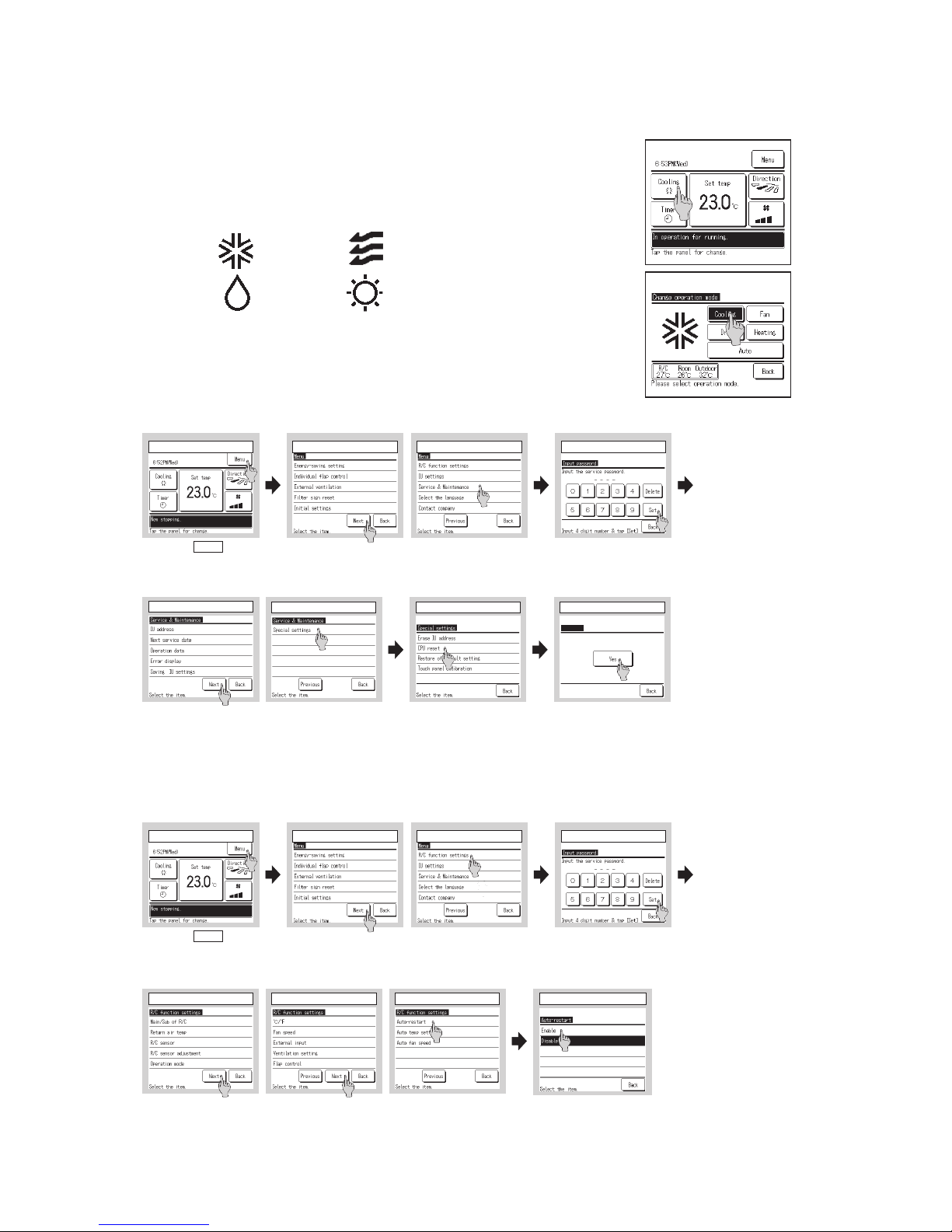
1.2 Operation control function by the wired remote control
Cooling Fan
Dry Heating
(1) Switching sequence of the operation mode switches of remote control
(a) Tap the change operation mode button on the TOP screen.
(b) When the change operation mode screen is displayed, tap the button of desired mode.
(c) When the operation mode is selected, the display returns to the TOP screen.
Icons displayed have the following meanings.
Notes(1) Operation modes which cannot be selected depending on combinations of IU and
OU are not displayed.
Notes(2) Whe n the Au to is selected, the cool ing a nd heati ng swi tching o perat ion is
performed automatically according to indoor and outdoor temperatures.
(2) CPU reset
Reset CPU from the remote control as follows.
(3) Power failure compensation function (Electric power supply failure)
Enable the Auto-restart function from the remote control as follows.
①Tap the Menu button
on the TOP screen.
②,③ Main menu screen is displayed.
Tap the “Service & Maintenance” on the menu screen.
④Display the service
password input screen.
Enter the service password
(4-digit number).
①TOP screen ②Menu screen 1 ③ Menu screen 3 ④ Service password input
①Tap the Menu button
on the TOP screen.
②,③ Main menu screen is displayed.
Tap the “Service & Maintenance” on the menu screen.
④Display the service
password input screen.
Enter the service password
(4-digit number).
①TOP screen ②Menu screen 1 ③ Menu screen 3 ④ Service password input
⑤
Service & maintenance menu 1
⑥
Service & maintenance menu 2
⑤,⑥ Service & maintenance menus are displayed.
⑦ Special settings
⑦Special settings
CPU reset : Micr ocompu ters of IU
and OU connected are reset
(State of restoration after
power failure).
⑧CPU reset
All microcomputers on the R/C operated,
other R/Cs, IUs and OUs are reset (State
of restoration after power failure).
Tap [Yes] to reset CPU
⑤,⑥,⑦Display the R/C setting menu screens.
⑤R/C setting menu 1 ⑥R/C setting menu 2 ⑦R/C setting menu 3
⑱ Auto-restart
Enable : It returns to the state be fore the supply
power fai lure as soon as the p ower is
restored (After the end of the primary
control at the power on).
Disable : It stops after the restoration of power
supply, regardless the state of operation
before the power failure.
⑱Auto-restart
Set the state of operation to be started when the
power supply is restored after a power failure.
⑧ CPU reset
CPUreset
Restartafterreset
IfOK,
tap[Set.
]
Model RC-EX1A
Page 7

– 5 –
'14 • KX-SM-202
• Since it memorizes always the condition of remote control, it starts operation according to the contents of memory no
sooner than normal state is recovered after the power failure. Although the auto swing stop position and the timer mode are
cancelled, the weekly timer setting is restored with the holiday setting for all weekdays.
After recovering from the power failure, it readjusts the clock and resets the holiday setting for each weekday so that the
setting of weekly timer becomes effective.
• Content memorized with the power failure compensation are as follows.
Note (1) Items (f), (g) and (h) are memorized regardless whether the power failure compensation is effective or not while the setting of silent mode is cancelled
regardless whether the power failure compensation is effective or not.
(a)
At power failure – Operating/stopped
If it had been operating under the off timer mode, sleep timer mode, the state of stop is memorized. (Although the
timer mode is cancelled at the recovery from power failure, the setting of weekly timer is changed to the holiday
setting for all weekdays.)
(b)
Operation mode
(c)
Airowvolumemode
(d)
Room temperature setting
(e)
Louver auto swing/stop
However, the stop position (4-position) is cancelled so that it returns to Position (1).
(f)
“Remote control function items” which have been set with the remote control function setting (“Indoor function
items” are saved in the memory of indoor unit.)
(g)
Upper limit value and lower limit value which have been set with the temperature setting control
(h)
Sleep timer and weekly timer settings (Other timer settings are not memorized.)
Page 8
– 6 –
'14 • KX-SM-202
⑥ Operation and setting from remote control
A: Refer to the in struction manual for RC-EX series.
B: Refer to the in stallation manual for RC-EX series.
C: Loading a utili ty software vie Internet
○: Nearly same fun ction setting and operations are possible.
△: Similar functio n setting and operations are possible.
Description
RC-EX
series
RC-E4
RC-E5
1. Remote Control network
1
1
2
3
4
5
6
7
8
9
Control plural indoor units
by a single remote control
A remote controller can control plural indoor units up to 16 (in one group of remote control network). An address is set to each indoor unit.
○ ○
2
A maximum of two remote controllers (include option wireless) can be connected to one indoor unit. Set one to "Master" and the other to "Slave".
B ○
2. TOP screen, Switch manipulati on A
Menu "Control", "Settings", or "Details" can be selected. (3.-19.) A
Operation mode "Cooling", "Heating", "Fan" or "Dry" can be set. A
Set temp. "Set temperature" can be set by 0.5℃ interval. A
○A "Air flow direction". [Individual flap control setting] can be set. Air flow direction
Fan speed "Fan speed" can be set. A
Timer setting "Timer operation" can be set. A
ON/OFF "On/Off operation of the system" can be done. A
○
○
○
○
○
High power SW "High power operation" or "Normal operation" can be selected. A
Energy-saving SW "Energy-saving operation" or "Normal operation" can be selected. A
3.Energy-sa ving setting [メニュー] 1番目 A
1
△
2 Peak-cut timer
[Administrator password]
3 Automatic temp. set back
[Administrator password]
△
4. Individual flap contro l setting [メニュー] 3番目 A
The moving range (the positions of upper limit and lower limit) of the flap for individual air outlet port can be set. A
5. Ventilation [メニュー] 4番目
1
External ventilation
(In combination with
ventilator)
On/Off operation of the external ventilator can be done.
・The settings of [Interlock] with AC (air-conditioner), [Single operation] of ventilator or operation [invalid] of ventilation can be done through
[Ventilation settings] in the [Remote controller] menu.
○
○A
A
A
A
Master/slave setting of remote
controllers
Setting & display item
Individual flap control setting
Auto OFF timer
[Administrator password]
For preventing the timer from keeping ON, set hours to stop operation automatically with this timer.
・The selectable range of setting time is from 30 to 240 minutes (10minutes interval)
・When setting is "Valid", this timer will activate whenever the ON timer is set.
Power consumption can be reduced by restricting the maximum capacity.
Set the [Start time], the [End time] and the capacity limit % (Peak-cut %).
・4-operation patterns per day can be set at maximum.
・The setting time can be changed by 5-minutes inter val.
・The selectable range of capacity limit % (Peak-cut %) is from 0% to 40-80% (20% interval).
・Holiday setting is available.
After the elapse of the set time period, the current set temp. will be set back to the [Set back temp.]
・The setting can be done in cooling and heating mode respectively.
・The selectable range of the set time is from 20 min. to 120 min. (10 min. interval).
・Set the [Set back temp.] by 1℃ interval.
6.Filter sign r eset [メニュー] 7番目 A
○
1 Filter sign reset B
2 Setting next cleaning date A
7.Initial set tings
[メニュー] 8番目
1 Clock setting △
2 Date and time display A
A
3 Summer time A
4 Contrast A
5 Backlight A
6 Controller sound A
8.Timer setting s
[メニュー] 9番目 A
1
Set On timer by hour
・The period of set time can be set within the range of 1hour-12hours (1hr interval).
・The operation mode, set temp and fan speed at starting operation can be set.
2 Set Off timer by hour
・The period of set time can be set within the range of 1hour-12hours (1hr interval).
3 Set On timer by clock
・The set clock time can be set by 5 minutes interval.
・[Once (one time only)] or [Everyday] operation can be switched.
・The operation mode, set temp and fan speed at starting operation can be set.
4 Set Off timer by clock
・The set clock time can be set by 5 minutes interval.
・[Once (one time only)] or [Everyday] operation can be switched.
5 Confirmation of timer settings A
[メニュー] 10番目
1 Weekly timer
[Administrator password]
△
・8-operation patterns per day can be set at a maximum.
・The setting clock time can be set by 5 minutes inter val.
・Holiday setting is available.
・The operation mode, set temp and fan speed at starting operation can be set.
△
△
[メニュー]?[次ページ] 1番目
1
When leaving home for a long period like a vacation leave, the unit can be operated to maintain the room temperature not to be hotter in summer or not to be colder in winter.
・The judgment to switch the operation mode (Cooling⇔Heating) is done by the both factors of the set temp. and outdoor air temp.
・The set temp. and fan speed can be set.
△
△
△
△
A
A
A
A
A
A
Home leave mode
[Administrator password]
9.Weekly timer
10.Home leave mode
The filter sign can be reset.
The next cleaning date can be set.
When select [Valid], the +1hour adjustment of current time can be set.When select [Invalid], the [Summer time] adjustment can be reset.
The current date and time can be set or revised.
[Display] or [Hide] the date and/or time can be set, and the [12H] or [24H] display can be set.
The contrast of LCD can be adjusted higher or lower.
Switching on/off a light can be set and the period of the lighting time can be set within the range of 5sec-90sec (5sec interval).
It can set with or without [Controller sound (beep sound)] at touching panel.
The period of time to start operation after stopping can be set.
The period of time to stop operation after starting can be set.
The clock time to start operation can be set.
The clock time to stop operation can be set.
Status of timer settings can be seen.
On timer and Off timer on weekly basis can be set.
⑥ Operation and setting from remote control (continued)
Description
[Administrator password]
1
Enable/Disable setting ・Enable/Disable setting of operation can be set. [On/Off] [Change set temp.] [Change operation mode] [Change air flow direction]
[Individual flap control setting][Fan speed] [High power operation] [Energy-saving operation] [Timer settings] [Weekly timer setting]
・Request for administrator password can be set. [Individual flap control setting][Weekly timer][Energy-saving setting][Home leave mode][Administrator settings]
2
Silent mode timer The period of time to operate the outdoor unit by prioritizing the quietness can be set.
・The [Start time] and the [End time] for operating outdoor unit in silent mode can be set. ・The period of the operation time can be set once a day by 5 minutes interval.
3 Setting temp. range The upper/lower limit of indoor temp. setting range can be set.
・The limitation of indoor temp. setting range can be set for each operation mode in cooling and heating.
4 Temp. increment setting The temp increment setting can be changed by 0.5℃ or 1.0℃. A
5
RC display setting
Register [Room name] [Name of I/U]
Display [indoor temp.] or not.
Display [inspection code] or not.
Display [Heating stand-by] [Defrost operation] [Auto cooling/heating] or not
6
1
2
3
4
5
6
1
2
3
4
5
6
7
8
9
10
11
Change administrator password The administrator password can be changed. (Default setting is "0000")
The administrator password can be reset.
[Service password]
Installation date The [Installation date] can be registered.
・
When registering the [Installation date], the [Next service date] is displayed automatically. (For changing the [Next service date]. please refer the item of [Service & Maintenance].)
Service contact The [Service contact] can be registered and can be displayed on the RC.
・The [Contact company] can be registered within 10 characters. ・The [Contact phone] can be registered within 13 digits.
Test run
Cooling test run
On/Off operation of the test run can be done.
The [Cooling test run] can be done at 5℃ of set temp. for 30 minutes. ○
Drain pump test run Only the drain pump can be operated. ○
Compressor Hz fixed oper ation
The [Test run] operation can be done with fixed compressor Hz set by installer. ○
Static pressure adjust ment In case of combination with only the ducted indoor unit which has a function of static pressure adjustment, the static pressure is adjustable.
Change auto-address The set address of each indoor unit decided by auto-address setting method can be changed to any other address. (For multiple KX units only) B
Address setting of Main IU
[Service password]
Main/Sub RC setting The setting of [Main/Sub RC] can be changed. B
RC sensor
The [Valid/Invalid] setting of [RC sensor] can be done. Respective setting in cooling and heating is available.
RC sensor adjustment The offset value of [RC sensor] sensing temp. can be set respectively in heating and cooling.
・The setting range of offset value is ±3℃ both in cooling and heating.
Operation mode The [Valid/Invalid] setting of [Auto][Cooling][Heating] and [Dry] can be done respectively. B
Fan speed The setting of [Fan speed] can be done from following patterns.・1-speed, 2-speeds (Hi-Me), 2-speeds (Hi-Lo), 3-speeds, 4-speeds. B
External input The applicable range ([Individual] or [All units]) of CnT input to the multiple indoor units connected in one control system.
・[Individual] : Only the unit received CnT input signal.・[All units] : All the units connected to one control system received CnT input signal.
Ventilation setting The setting of [Invalid] operation of ventilator, [Interlock] with AC or [Independent] of ventilator can be selected.
・When setting [Interlock], the operation of external ventilator is interlocked with the operation of AC ・When setting [Independent], only the operation of external ventilator is available.
Flap control The [Flap control] method can be switched to[Stop at fixed position] or [Stop at any position]・[Stop at fixed position] : Stop the flap at a certain position
among the designated 4 positions.・[Stop at any position] : Stop the flap at any arbitrary position just after the stopping command from RC was sent.
Auto-restart The operation control method after recovery of power blackout happened during operation can be set. B
Auto temp. setting [Valid] or [Invalid] of [Auto temp. setting] can be selected. B
Auto fan speed setting [Valid] or [Invalid] of [Auto fan speed setting] can be selected. B
Main indoor unit address can be set.
・Only the Main indoor unit can change operation mode and the Sub indoor units dominated by the Main indoor unit shall follo w.
・The Main indoor unit can domain 10 indoor units a t a maximum.
12.Installer settings
13.RC function settings
Setting & display item
11. Administrato r settings
[Service password]
High ceiling The fan tap of indoor fan can be changed. ・[Standard] [High ceiling 1] [High ceiling 2] can be selected. B
Filter sign The setting of filter sign display timer can be done from following patterns. B
External input 1
The content of control by external input can be changed.・The selectable contents of control are [On/Off] [Permission/Prohibition] [Cooling/heating] [Emergency stop]
External input 1 signal The type of external input signal ([Level input]/[Pulse input]) can be changed. B
External input 2 ・The selectable contents of control are [On/Off] [Permission/Prohibition] [Cooling/heating] [Emergency stop] B
External input 2 signal The type of external input signal ([Level input]/[Pulse input]) can be changed. B
Heating thermo-off tem p. adjust.
The judgment temp. of heating thermo-off can be adjusted within the range from 0 to +3℃(1℃ interval) B
Return air sensor adjus t. The sensing temp. of return air temp. sensor built in the indoor unit can be adjusted within the range of ±2℃. B
Fan control i n heating t hermo OFF
The fan control method at heating thermo-off can be changed.・The selectable fan control methods are [Low] [Set fan speed] [Intermittent] [Stop]. B
Anti-frost temp. The judgment temp. of anti-frost control for the indoor unit in cooling can be changed to [Temp. High] or [Temp. Low]. B
Anti-frost control When the anti-frost control of indoor unit in cooling is activated, the fan speed can be changed.
Drain pump operation In any operation mode in addition to cooling and dry mode, the setting of drain pump operation can be done. B
Residual fan operation in cooling
The time period of residual fan operation after stopping in cooling mode can be set. B
Residual fan operation in heating
The time period of residual fan operation after stopping or thermo-off in heating mode can be set. B
Intermittent fan opera tion in hea ting
The fan operation rule following the residual fan operation after stopping or thermo-off in heating mode can be set. B
Fan circulat or operatio n In case that the fan is operated as the circulator, the fan control rule can be set. B
Control pressure adjust . (For OA processing uni t only)
When only the OA processing units are operated, control pressure value can be changed. B
Auto operation mode The [Auto rule selection] for switching the operation mode automatically can be selected from 3 patterns. B
Thermo. rule setting When selecting [Outdoor air temp. control], the judgment temp can be offset by outdoor temp.. B
Auto fan speed control
Under the [Auto fan speed control] mode, the switching range of fan speed can be selected from following 2 patterns [Auto 1] [Auto 2]. ・[Auto 1] : Hi ⇔Me⇔Lo・[Auto 2] : P-hi⇔Hi⇔Me ⇔Lo
[Service password]
1
2
3
4
5
6
IU address No. Max. 16 indoor units can be connected to one remote control, and all address No. of the connected indoor units can be displayed.
・The indoor unit conforming to the address No. can be identified by selecting the address No. and tapping [Check] to operate the indoor fan.
Next service date The [Next service date] can be registered.・The [Next service date] and [Service contact] is displayed on the [Periodical check] message screen. AB
Operation data Total 39 items of [Operation data] for indoor unit and outdoor unit can be displayed. B
Error history [Date and time of error occurred] [I/U address] [Error code] for Max. 16 latest cases of error history can be displayed. B
Display anomaly data The operation data just before the latest error stop can be displayed. B
Reset periodical check The timer for the periodical check can be reset. B
Saving I/U settings The I/U settings memorized in the indoor PCB connected to the remote control can be saved in the memory of the remote control.
Special settings [Erase I/U address] [CPU reset] [Initializing] [Touch panel calibration] B
14. I/U settings
15.Service & Maintenance
1
2
3
4
5
6
7
8
9
10
11
12
13
14
15
16
17
18
19
20
(4) Operation and setting from remote control
Page 9
– 7 –
'14 • KX-SM-202
⑥ Operation and setting from remote control (continued)
Description
[Administrator password]
A
1
Enable/Disable setting ・Enable/Disable setting of operation can be set. [On/Off] [Change set temp.] [Change operation mode] [Change air flow direction]
[Individual flap control setting][Fan speed] [High power operation] [Energy-saving operation] [Timer settings] [Weekly timer setting]
・Request for administrator password can be set. [Individual flap control setting][Weekly timer][Energy-saving setting][Home leave mode][Administrator settings]
2
Silent mode timer The period of time to operate the outdoor unit by prioritizing the quietness can be set.
・The [Start time] and the [End time] for operating outdoor unit in silent mode can be set. ・The period of the operation time can be set once a day by 5 minutes interval.
3 Setting temp. range The upper/lower limit of indoor temp. setting range can be set.
・The limitation of indoor temp. setting range can be set for each operation mode in cooling and heating.
4 Temp. increment setting The temp increment setting can be changed by 0.5℃ or 1.0℃. A
5
RC display setting
Register [Room name] [Name of I/U]
Display [indoor temp.] or not.
Display [inspection code] or not.
Display [Heating stand-by] [Defrost operation] [Auto cooling/heating] or not
○
△
△
△
△
○
6
1
2
3
4
5
6
1
2
3
4
5
6
7
8
9
10
11
Change administrator password The administrator password can be changed. (Default setting is "0000")
The administrator password can be reset.
A
B
[Service password]
B
Installation date The [Installation date] can be registered.
・
When registering the [Installation date], the [Next service date] is displayed automatically. (For changing the [Next service date]. please refer the item of [Service & Maintenance].)
B
Service contact The [Service contact] can be registered and can be displayed on the RC.
・The [Contact company] can be registered within 10 characters. ・The [Contact phone] can be registered within 13 digits.
Test run
Cooling test run
On/Off operation of the test run can be done.
The [Cooling test run] can be done at 5℃ of set temp. for 30 minutes. ○
Drain pump test run Only the drain pump can be operated. ○
Compressor Hz fixed oper ation
The [Test run] operation can be done with fixed compressor Hz set by installer. ○
Static pressure adjust ment In case of combination with only the ducted indoor unit which has a function of static pressure adjustment, the static pressure is adjustable.
Change auto-address The set address of each indoor unit decided by auto-address setting method can be changed to any other address. (For multiple KX units only) B○△
Address setting of Main IU
[Service password]
B
Main/Sub RC setting The setting of [Main/Sub RC] can be changed. B
RC sensor
The [Valid/Invalid] setting of [RC sensor] can be done. Respective setting in cooling and heating is available.
B
RC sensor adjustment The offset value of [RC sensor] sensing temp. can be set respectively in heating and cooling.
・The setting range of offset value is ±3℃ both in cooling and heating.
B
Operation mode The [Valid/Invalid] setting of [Auto][Cooling][Heating] and [Dry] can be done respectively. B
Fan speed The setting of [Fan speed] can be done from following patterns.・1-speed, 2-speeds (Hi-Me), 2-speeds (Hi-Lo), 3-speeds, 4-speeds. B
External input The applicable range ([Individual] or [All units]) of CnT input to the multiple indoor units connected in one control system.
・[Individual] : Only the unit received CnT input signal.・[All units] : All the units connected to one control system received CnT input signal.
B
Ventilation setting The setting of [Invalid] operation of ventilator, [Interlock] with AC or [Independent] of ventilator can be selected.
・When setting [Interlock], the operation of external ventilator is interlocked with the operation of AC ・When setting [Independent], only the operation of external ventilator is available.
B
Flap control The [Flap control] method can be switched to[Stop at fixed position] or [Stop at any position]・[Stop at fixed position] : Stop the flap at a certain position
among the designated 4 positions.・[Stop at any position] : Stop the flap at any arbitrary position just after the stopping command from RC was sent.
B
Auto-restart The operation control method after recovery of power blackout happened during operation can be set. B
○
○
△
○
○
○
○
○
○
Auto temp. setting [Valid] or [Invalid] of [Auto temp. setting] can be selected. B
Auto fan speed setting [Valid] or [Invalid] of [Auto fan speed setting] can be selected. B
△B
B
B
B
A
A
A
A
Main indoor unit address can be set.
・Only the Main indoor unit can change operation mode and the Sub indoor units dominated by the Main indoor unit shall follo w.
・The Main indoor unit can domain 10 indoor units a t a maximum.
12.Installer settings
13.RC function settings
Setting & display item
11. Administrator settings
RC-EX
series
RC-E4
RC-E5
[Service password]
B
High ceiling The fan tap of indoor fan can be changed. ・[Standard] [High ceiling 1] [High ceiling 2] can be selected. B
Filter sign The setting of filter sign display timer can be done from following patterns. B
External input 1
The content of control by external input can be changed.・The selectable contents of control are [On/Off] [Permission/Prohibition] [Cooling/heating] [Emergency stop]
B
External input 1 signal The type of external input signal ([Level input]/[Pulse input]) can be changed. B
External input 2 ・The selectable contents of control are [On/Off] [Permission/Prohibition] [Cooling/heating] [Emergency stop] B
External input 2 signal The type of external input signal ([Level input]/[Pulse input]) can be changed. B
Heating thermo-off tem p. adjust.
The judgment temp. of heating thermo-off can be adjusted within the range from 0 to +3℃(1℃ interval) B
Return air sensor adjus t. The sensing temp. of return air temp. sensor built in the indoor unit can be adjusted within the range of ±2℃. B
Fan control i n heating t hermo OFF
The fan control method at heating thermo-off can be changed.・The selectable fan control methods are [Low] [Set fan speed] [Intermittent] [Stop]. B
Anti-frost temp. The judgment temp. of anti-frost control for the indoor unit in cooling can be changed to [Temp. High] or [Temp. Low]. B
Anti-frost control When the anti-frost control of indoor unit in cooling is activated, the fan speed can be changed.
B
Drain pump operation In any operation mode in addition to cooling and dry mode, the setting of drain pump operation can be done. B
Residual fan operation in cooling
The time period of residual fan operation after stopping in cooling mode can be set. B
Residual fan operation in heating
The time period of residual fan operation after stopping or thermo-off in heating mode can be set. B
Intermittent fan opera tion in hea ting
The fan operation rule following the residual fan operation after stopping or thermo-off in heating mode can be set. B
Fan circulat or operatio n In case that the fan is operated as the circulator, the fan control rule can be set. B
Control pressure adjust . (For OA processing uni t only)
When only the OA processing units are operated, control pressure value can be changed. B
○
○
○
○
△
△
○
○
○
○
○
○
○
○
Auto operation mode The [Auto rule selection] for switching the operation mode automatically can be selected from 3 patterns. B
Thermo. rule setting When selecting [Outdoor air temp. control], the judgment temp can be offset by outdoor temp.. B
Auto fan speed control
Under the [Auto fan speed control] mode, the switching range of fan speed can be selected from following 2 patterns [Auto 1] [Auto 2]. ・[Auto 1] : Hi ⇔Me⇔Lo・[Auto 2] : P-hi⇔Hi⇔Me⇔Lo
B
[Service password]
B
1
2
3
4
5
6
IU address No. Max. 16 indoor units can be connected to one remote control, and all address No. of the connected indoor units can be displayed.
・The indoor unit conforming to the address No. can be identified by selecting the address No. and tapping [Check] to operate the indoor fan.
B
Next service date The [Next service date] can be registered.・The [Next service date] and [Service contact] is displayed on the [Periodical check] message screen. AB
Operation data Total 39 items of [Operation data] for indoor unit and outdoor unit can be displayed. B
Error history [Date and time of error occurred] [I/U address] [Error code] for Max. 16 latest cases of error history can be displayed. B
Display anomaly data The operation data just before the latest error stop can be displayed. B
Reset periodical check The timer for the periodical check can be reset. B
Saving I/U settings The I/U settings memorized in the indoor PCB connected to the remote control can be saved in the memory of the remote control.
B
Special settings [Erase I/U address] [CPU reset] [Initializing] [Touch panel calibration] B
○
○
△
○
△
△
Confirmation of Inspect ion The address No, of anomalous indoor/outdoor unit and error code are displayed.
USB connection Weekly timer setting and etc., can be set from PC.
C
A
17.PC connection
14. I/U settings
15.Service & Maintenance
16.Inspection
1
2
3
4
5
6
7
8
9
10
11
12
13
14
15
16
17
18
19
20
Page 10
– 8 –
'14 • KX-SM-202
Model RC-E5
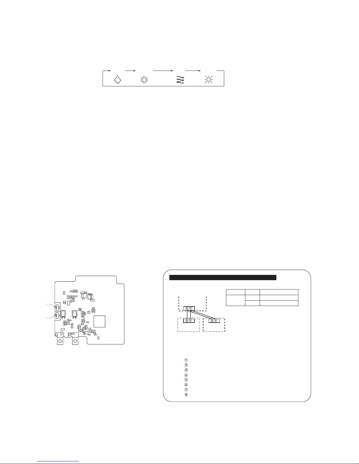
(1) Switching sequence of the operation mode switches of remote control
DRY COOL FAN HEAT
(2) CPU reset
This functions when “CHECK” and “ESP” buttons on the remote control are pressed simultaneously. Operation is same as that
of the power supply reset.
(3) Power failure compensation function (Electric power supply failure)
• This becomes effective if “Power failure compensation effective” is selected with the setting of remote control function.
• Since it memorizes always the condition of remote control, it starts operation according to the contents of memory no
sooner than normal state is recovered after the power failure. Although the auto swing stop position and the timer mode are
cancelled, the weekly timer setting is restored with the holiday setting for all weekdays.
After recovering from the power failure, it readjusts the clock and resets the holiday setting for each weekday so that the
setting of weekly timer becomes effective.
• Content memorized with the power failure compensation are as follows.
Note (1) Items (f), (g) and (h) are memorized regardless whether the power failure compensation is effective or not while the setting of silent mode is cancelled
regardless whether the power failure compensation is effective or not.
(a)
At power failure – Operating/stopped
If it had been operating under the off timer mode, sleep timer mode, the state of stop is memorized. (Although the
timer mode is cancelled at the recovery from power failure, the setting of weekly timer is changed to the holiday
setting for all weekdays.)
(b)
Operation mode
(c)
Airowvolumemode
(d)
Room temperature setting
(e)
Louver auto swing/stop
However, the stop position (4-position) is cancelled so that it returns to Position (1).
(f)
“Remote control function items” which have been set with the remote control function setting (“Indoor function
items” are saved in the memory of indoor unit.)
(g)
Upper limit value and lower limit value which have been set with the temperature setting control.
(h)
Sleep timer and weekly timer settings (Other timer settings are not memorized.)
[Parts layout on remote control PCB]
X
Y
SW2
SW1
A
B
M
S
親
子
SW1
SW2
Master/ slave setting when more than one remote controls are used
A maximum of two remote controls can be connected to one indoor unit (or one group of indoor units.)
Remote control cord (no polarity)
Remote control
SW1 "Master"
Switch Setting Contents
M Master remote control
SW1
S Slave remote control
Remote control
SW1 "Slave"
Indoor units
Note (1) Don’t change SW2 because it is not used normally.
Caution
When using multiple remote controls, the following dispiays or settings
cannot be done with the slave remote control. It is available only with
the master remote control.
Louver position setting (set upper or lower limit of swinging range)
Setting indoor unit functions
Setting temperature range
Operation data display
Error data display
Silent mode setting
Test operation of drain pump
Remote control sensor setting
Page 11
– 9 –
'14 • KX-SM-202
1.3 Operation control function by the indoor control
(1) Operations of functional items during cooling/heating
Cooling Heating
Dehumidifying
Fan
Operation
Functional item
Thermostat
ON
Thermostat
ON
Thermostat
OFF
Thermostat
OFF
Hot start
(Defrost)
Compressor
4-way valve
Outdoor unit fan
Indoor unit fan
Drain pump
(3)
(2)
(2)
/
/
()
()
/
/
/
/
Thermostat ON:
Thermostat OFF:
(2)
/
(2)
Note (1) : Operation : Stop /: Turned ON/OFF by the control other than the room temperature control.
(2) ON during the drain motor delay control.
(3) Drain pump ON setting may be selected with the indoor unit function setting of the wired remote control.
(2) Dehumidifying operation
Return air temperature thermistor [Th
I-A (by the remote control when the remote control thermistor is enabled)] controls
the indoor temperature environment simultaneously.
(a) Operation is started in the cooling mode. When the difference between the return air temperature and the setting
temperature is 2°C or less, the indoor unit fan tap is brought down by one tap. That tap is retained for 3 minutes
after changing the indoor unit fan tap.
(b) If the return air temperature exceeds the setting temperature by 3°C during dehumidifying operation, the indoor unit
fan tap is raised. That tap is retained for 3 minutes after changing the indoor unit fan tap.
(c) If the thermostat OFF is established during the above control, the indoor unit fan tap at the thermostat ON is retained
so far as the thermostat is turned OFF.
(3) Timer operation
(a) RC-EX1A
(i) Sleep timer
Set the time from the start to stop of operation. The time can be selected in the range from 30 to 240 minutes (in the
unit of 10-minute).
Note (1) Enable the “Sleep timer” setting from the remote control. If the setting is enabled, the timer operates at every time.
(ii) Set OFF timer by hour
Set the time to stop the unit after operation, in the range from 1 to 12 hours (in the unit of hour).
(iii) Set ON timer by hour
Set the time to start the unit after the stop of operation, in the range from 1 to 12 hours (in the unit of hour). It is
allowed also to set simultaneously the indoor temperature, operation mode, air flow rate and warm-up enabled/
disabled.
(iv) Set ON timer by clock
Set the time to start operation. The time can be set in the unit of 5-minute. This setting can be activated only once
oratevery time. It is allowed alsotosetsimultaneouslytheindoor temperature, operation mode, air owrateand
warm-up enabled/disabled.
Note (1) It is necessary to set the clock to use this timer.
(v) Set OFF timer by clock
Set the time to stop operation. The time can be set in the unit of 5-minute. This setting can be activated only once or
at every time.
Note (1) It is necessary to set the clock to use this timer.
(vi) Weekly timer
Set the ON or OFF timer for a week. Up to 8 patterns can be set for a day. The day-off setting is provided for
holidays and non-business days.
Note (1) It is necessary to set the clock to use the weekly timer.
Page 12
– 10 –
'14 • KX-SM-202
(vii)
Combination of patterns which can be set for the timer operations
Note (1) : Allowed : Not
Sleep time
Sleep time
Set OFF timer by hour
Weekly timer
Set ON timer by hour
Set OFF timer by clock
Set ON timer by clock
Set OFF timer by hour
Set ON timer by hour
Set OFF timer by clock
Set ON timer by clock
Weekly timer
(b) RC-E5
(i) Sleep timer
Set the duration of time from the present to the time to turn off the air-conditioner.
It can be selected from 10 steps in the range from “OFF 1 hour later” to “OFF 10 hours later”. After the sleep timer
setting, the remaining time is displayed with progress of time in the unit of hour.
(ii) OFF timer
Time to turn OFF the air-conditioner can be set in the unit of 10 minutes.
(iii) ON timer
Time to turn ON the air-conditioner can be set. Indoor temperature can be set simultaneously.
(iv) Weekly timer
Timer operation (ON timer, OFF timer) can be set up to 4 times a day for each weekday.
(v) Timer operations which can be set in combination
Timer
OFF timer
ON timer
Weekly timer
Timer
OFF timer
ON timer
Weekly timer
Note (1) : Allowed : Not
Item
Item
(2) Since the ON timer, sleep timer and OFF timer are set in parallel, when the times to turn ON and OFF the airconditioner are duplicated, the setting
of the OFF timer has priority.
(4) Remote control display during the operation stop
When the operation is stopped (the power supply is turned ON), it displays preferentially the “Room temperature”, “Center/
Remote”, “Filter sign”, “Inspection” and “Timer operation”.
(5) Hot start (Cold draft prevention at heating)
(a) Operating conditions
When either one of following conditions either of (i) to (iv), the hot start control is performed.
(i) From stop to heating operation
(ii) From cooling to heating operation
(iii) From heating thermostat OFF to ON
(iv) After completing the defrost control (only on units with thermostat ON)
(b) Contents of operation
(i) Indoor fan motor control at hot start
1) Within 7 minutes after starting heating operation, the fan mode is determined depending on the condition of
thermostat (fan control with heating thermostat OFF).
a) Thermostat OFF
i) Operates according to the fan control setting at heating thermostat OFF.
ii) Even if it changes from thermostat OFF to ON, the fan continues to operate with the fan control at thermostat
OFF till the heat exchanger thermistor (ThI-R1 or R2, whichever higher) detects 35°C or higher.
iii) When the heat exchanger thermistor (ThI-R1 or R2, whichever higher) detects 35°C or higher, the fan
operateswiththesetairowvolume.
Page 13

– 11 –
'14 • KX-SM-202
b) Thermostat ON
i) When the heat exchanger thermistor (ThI-R1 or R2, whichever higher) detects 25°C or lower, the fan is
turned OFF and does not operate.
ii) When the heat exchanger thermistor (ThI-R1 or R2, whichever higher) detects 25°C or higher, the fan
operates with the fan control at heating thermostat OFF.
iii) When the heat exchanger thermistor (ThI-R1 or R2, whichever higher) detects 35°C or higher, the fan
operateswiththesetairowvolume.
c) Ifthe fan controlatheatingthermostat OFFissetat the “Setairowvolume”(from the remotecontrol),the
fanoperateswiththesetairowvolumeregardlessofthethermostatON/OFF.
2) Once the fan motor is changed from OFF to ON during the thermostat ON, the indoor fan motor is not turned
OFF even if the heat exchanger thermistor detects lower than 25
°C.
Note (1) When the defrost control signal is received, it complies with the fan control during defrosting.
3) Once the hot start is completed, it will not restart even if the temperature on the heat exchanger thermistor drops.
(ii) During the hot start, the louver is kept at the horizontal position.
(iii) When the fan motor is turned OFF for 7 minutes continuously after defrosting, the fan motor is turned ON regardless
of the temperatures detected with the indoor heat exchanger thermistors (ThI-R1, R2).
(c) Ending condition
(i) If one of following conditions is met during the hot start control, this control is terminated, and the fan is operated with
thesetairowvolume.
1) Heat exchanger thermistor (ThI-R1 or R2, whichever higher) detects 35
°C or higher.
2) It has elapsed 7 minutes after starting the hot start control.
(6) Hot keep
Hot keep control is performed at the start of the defrost control.
(a) Control
(i) When the indoor heat exchanger temperature (detected with ThI-R1 or R2) drops to 35°C or lower, the speed of
indoor fan is changed to the lower tap at each setting.
(ii) During the hot keep, the louver is kept at the horizontal position.
(b) Ending condition
Whentheindoorfan isatthe lowertapat eachsetting,itreturnsto thesetairow volumeastheindoorheatexchanger
temperature rises to 45°C or higher.
(7) Auto swing control (FDT, FDTC, FDTW, FDTS, FDE only)
(a) RC-EX1A
(i) Louver control
1) To operate the swing louver when the air conditioner is operating, press the “Direction” button on the TOP screen of
remote control. The wind direction select screen will be displayed.
2) Toswingthelouver,touchthe“Autoswing”button.Theloverwillmoveupanddown.Toxtheswinglouverata
position, touch one of [1] - [4] buttons. The swing lover will stop at the selected position.
3) Louver operation at the power on with a unit having the louver 4-position control function
The louver swings one time automatically (without operating the remote control) at the power on.
This allows the microcomputer recognizing and inputting the louver motor (LM) position.
(ii) Automatic louver level setting during heating
At the hot start and the heating thermostat OFF, regardless whether the auto swing switch is operated or not (auto
swing or louver stop), the louver takes the level position (in order to prevent blowing of cool wind). The louver position
display LCD continues to show the display which has been shown before entering this control.
(iii) Louver free stop control
If you touch the “Menu” → “Next” → “R/C settings” buttons one after another on the TOP screen of remote control,
the “Flap control” screen is displayed. If the free stop is selected on this screen, the louver motor stops upon receipt of
the stop signal from the remote control. If the auto swing signal is received from the remote control, the auto swing will
start from the position before the stop.
Page 14
– 12 –
'14 • KX-SM-202
(b) RC-E5
(i) Louver control
1) Press the “LOUVER” button to operate the swing louver when the air conditioner is operating.
“SWING ” is displayed for 3 seconds and then the swing louver moves up and down continuously.
2) Toxtheswinglouverataposition,pressonetimethe“LOUVER”buttonwhiletheswinglouverismovingsothat
four stop positions are displayed one after another per second.
When a desired stop position is displayed, press the “LOUVER” button again. The display stops, changes to show
the “STOP 1
” for 5 seconds and then the swing louver stops.
3) Louver operation at the power on with a unit having the louver 4-position control function
The louver swings one time automatically (without operating the remote control) at the power on.
This allows inputting the louver motor (LM) position, which is necessary for the microcomputer to recognize the
louver position.
Note (1) If you press the “LOUVER” button, the swing motion is displayed on the louver position LCD for 10 second. The display changes to the
“SWING ” display 3 seconds later.
(ii) Automatic louver level setting during heating
At the hot start with the heating thermostat OFF, regardless whether the auto swing switch is operated or not (auto
swing or louver stop), the louver takes the level position (In order to prevent the cold start). The louver position display
LCD continues to show the display which has been shown before entering this control.
(iii) Louver-free stop control
When the louver-free stop has been selected with the indoor function of wired remote control “ POSITION”, the
louver motor stops when it receives the stop signal from the remote control. If the auto swing signal is received from the
remote control, the auto swing will start from the position where it was before the stop.
Note (1) When the indoor function of wired remote control “ POSITION” has been switched, switch also the remote control function “
POSITION” in the same way.
(8) Thermostat operation
(a) Cooling
(i) Thermostat is operated with the room temperature control.
(ii) Thermostat is turned ON or OFF relative to the set room temperature as shown below.
(iii) Thermostat is turned ON when the room temperature is in the range of -1 < Set temperature < +1 at the start of cooling
operation (including from heating to cooling).
(b) Heating
(i) Thermostat is operated with the room temperature control.
(ii) Thermostat is turned ON or OFF relative to the set room temperature as shown below.
(iii) Thermostat is turned ON when the room temperature is in the range of -1 < Set point < +1 at the start of cooling opera-
tion (including from cooling to heating).
Thermostat OFF
Set room temperature
Temperature drop
Temperature rise
-1
+1
Thermostat ON
Thermostat OFF
Heater OFF
Temperature rise
Temperature drop
Thermostat ON
Set room temperature
-1
+1
-1
+1
Heater ON
3C
◦
Page 15

– 13 –
'14 • KX-SM-202
(c) Fan control during heating thermostat OFF
(i) Following fan controls during the heating thermostat OFF can be selected with the indoor function setting of the wired
remote control.
① Low fan speed (Factory default), ② Set fan speed, ③ Intermittence, ④ Fan OFF
(ii) When the “Low fan speed (Factory default)” is selected, the following taps are used for the indoor fans.
・ For AC motor : Lo tap
・ For DC motor : ULo tap
(iii) When the “Set fan speed” is selected, it is operated with the set fan speed also in the thermostat OFF condition.
(iv) If the “Intermittence” is selected, following controls are performed:
1) If the thermostat is turned OFF during the heating operation, the indoor unit fan motor stops.
2) IndoorfanOFFisxedfor5minutes.Afterthe5minutes,theindoorfanisoperatedatLoorULofor2minutes.
In the meantime the louver is controlled at level.
3) After operating at Lo or ULo for 2 minutes, the indoor fan moves to the state of 1) above.
4) If the thermostat is turned ON, it moves to the hot start control.
5) When the heating thermostat is turned OFF, the remote control displays the temperature detected at the fan stop
and revises the temperature later when the indoor fan changes from Lo or ULo to stop.
The remote control uses the operation data display function to display temperatures and updates values of
temperature even when the indoor fan is turned OFF.
6) When the defrosting starts while the heating thermostat is turned OFF or the thermostat is turned OFF during
defrosting, the indoor fan is turned OFF. (Hot keep or hot start control takes priority.) However, the suction
temperature is updated at every 7-minute.
7) When the heating thermostat is turned ON or the operation is changed to another mode (including stop), this
control is stopped immediately, and the operating condition is restored.
(v) When the “Fan OFF” is selected, the fan on the indoor unit of which the thermostat has been turned OFF, is turned OFF.
The same occurs also when the remote control sensor is effective.
(d) Fan control during cooling thermostat OFF
(i) Following fan controls during the cooling thermostat OFF can be selected with the indoor function setting of the wired
remote control.
① Low fan speed, ② Set fan speed (Factory default), ③ Intermittence, ④ Fan OFF
(ii) When the “Low fan speed” is selected, the following taps are used for the indoor fans.
・ For AC motor : Lo tap
・ For DC motor : ULo tap
(iii) When the “Set fan speed” is selected, it is operated with the set fan speed also in the thermostat OFF condition.
(iv) If the “Intermittence” is selected, following controls are performed:
1) If the thermostat is turned OFF during the cooling operation, the indoor unit fan motor stops.
2) IndoorfanOFFisxedfor5minutes.Afterthe5minutes,theindoorfanisoperatedatLoorULofor2minutes.
3) After operating at Lo or ULo for 2 minutes, the indoor fan moves to the state of 1) above.
4) If the thermostat is turned ON, the fan starts operation at set fan speed.
5) When the cooling thermostat is turned OFF, the remote control displays the temperature detected at the fan stop
and revises the temperature later when the indoor fan changes from Lo or ULo to stop.
By using operation data display function at wireless remote control, the tempenature as displayad and the value is
updated including the fan stops.
6) When the cooling thermostat is turned ON or the operation is changed to another mode (including stop), this
control is stopped immediately, and the operating condition is restored.
(v) When the “Fan OFF” is selected, the fan on the indoor unit of which the thermostat has been turned OFF, is turned OFF.
The same occurs also when the remote control sensor is effective.
Page 16
– 14 –
'14 • KX-SM-202
(9) Filter sign
As the operation time (Total ON time of ON/OFF switch) accumulates to 180 hours
(1)
, “FILTER CLEANING” is displayed on
the remote control. (This is displayed when the unit is in trouble and under the centralized control, regardless of ON/OFF)
Note(1)Timesettingforthelter signcanbemadeasshownbelow usingtheindoor functionofwiredremotecontrol“FILTERSIGNSET”.(Itis setatTYPE1
at the shipping from factory.)
Filter sign setting
TYPE 1
TYPE 2
TYPE 3
TYPE 4
Function
Setting time: 180 hrs (Factory default)
Setting time: 600 hrs
Setting time: 1,000 hrs
Setting time: 1,000 hrs (Unit stop)
(2)
(2) After the setting time has elapsed, the “FILTER CLEANING” is displayed and, after operating for 24 hours further (counted also during the stop), the unit
stops.
(10) Compressor inching prevention control
(a) Once the indoor unit thermostat has been turned ON, the thermostat is not turned OFF for 2 minutes (*1) after the
compressor ON even if the thermostat is turned OFF at the state of (9).
Thermostat ON/OFF with this control
2 minutes2 minutes
OFF
ON
ON
ON
Stopped by remote control, etc.
*1
*1Even when the thermostat of another indoor
unit is turned ON after the compressor ON,
the thermostat is not turned OFF for 2 minutes
after the compressor ON.
*1
OFF
OFF
3 minutes delay
Thermostat OFF in the condition of (9)
Compressor
Indoor unit A
Thermostat
Indoor unit B
Thermostat
(11) Drain pump control
(a) This control is operated when the inverter frequency is other than 0 Hz during the cooling operation and automatic
cooling and dehumidifying operations.
(b) Drain pump ON condition continues for 5 minutes even when it enters the OFF range according to (i) above after turning
the drain pump ON, and then stops. The 5-minute delay continues also in the event of anomalous stop.
(c) The drain pump is operated with the 5-minute delay operation when the compressor is changed from ON to OFF.
(d) Even in conditions other than the above (such as heating, fan, stop, cooling thermostat OFF), the drain pump control is
performed by the drain detection.
(e) Following settings can be made using the indoor function setting of the wired remote control.
(i)
(ii)
(iii)
(iv)
Note (1) Values in 〔
〕
are for the RC-EX1A model.
ާStandardin cooling & dryި: Drain pump is run during cooling and dry.
ާOperate in standard & heatingި: Drain pump is run during cooling, dry and heating.
ާOperate in heating & fanި: Drain pump is run during cooling, dry, heating and fan.
ާOperate in standard & fanި: Drain pump is run during cooling, dry and fan.
(b) When the oil return control has started while the thermostat is turned ON, the thermostat is not turned OFF even if the
thermostat OFF condition is met during the oil return control.
Page 17
– 15 –
'14 • KX-SM-202
(12) Drain motor (DM) control
(a)
DraindetectionswitchisturnedONorOFFwiththeoatswitch(FS)andthetimer.
[
*
1]Draindetectionswitchisturned“ON”whentheoatswitch“Open”isdetectedfor3secondscontinuouslyinthe
drain detectable space.
[
*
2]Draindetectionswitchisturned“OFF”whentheoatswitch“Close”isdetectedfor10secondscontinuously.
(i) It detects always from 30 seconds after turning the power ON.
1) There is no detection of anomalous draining for 10 seconds after turning the drain pump OFF.
2) Turning the drain detection switch “ON” causes to turn ON the drain pump forcibly.
3) Turning the drain detection switch “OFF” releases the forced drain pump ON condition.
Normal state
[*1] [*2]
Normal state
Drain detection switch ON
Stop
(1)
Indoor unit operation mode
Control A
Control B
Compressor ON
Compressor OFF
Cooling Dry HeatingFan
(2)
Note (1) Including the stop from the cooling, dehumidifying, fan
and heating, and the anomalous stop
(2) Including the “Fan” operation according to the
mismatch of operation modes
(i) Control A
1) Iftheoatswitchdetectsanyanomalousdrainingcondition,theunitstopswiththeanomalousstop(displaysE9)
and the drain pump starts. After detecting the anomalous condition, the drain motor continues to be ON.
2) Itkeepsoperatingwhiletheoatswitchisdetectingtheanomalouscondition.
(ii) Control B
If the oat switch detects any anomalous drain condition, the drain motor is turned ON for 5 minutes, and at 10
seconds after the drain motor OFF it checks the oat switch. If it is normal, the unit is stopped under the normal
mode or, if there is any anomalous condition, E9 is displayed and the drain motor is turned ON. (The ON condition is
maintained during the drain detection.)
(b)
Indoor unit performs the control A or B depending on each operating condition.
(13) Operation check/drain pump test run operation mode
(a)
If the power is turned on by the dip switch (SW7-1) on the indoor PCB when electric power source is supplied, it enters the
mode of operation check/drain pump test run. It is ineffective (prohibited) to change the switch after turning power on.
(b) When the communication with the remote control has been established within 60 seconds after turning power on by the
dip switch (SW7-1) ON, it enters the operation check mode. Unless the remote control communication is established, it
enters the drain pump test run mode.
Note (1) To select the drain pump test run mode, disconnect the remote control connector (CNB) on the indoor PCB to shut down the remote control
communication.
(c) Operation check mode
There is no communication with the outdoor unit but it allows performing operation in respective modes by operating the
remote control.
(d) Drain pump test run mode
As the drain pump test run is established, the drain pump only operates and during the operation protective functions by
the microcomputer of indoor unit become ineffective.
(14) Cooling, dehumidifying frost protection
To prevent frosting during cooling mode or dehumidifying mode operation, the of thermostat-OFF if the indoor heat exchanger
temperature (detected with ThI-R) drops to 1.0 °C or lower at 4 minutes after the thermostat-ON. If the indoor unit heat
exchanger temperature is 1.0 °C or lower after 5 minutes, the indoor unit is controlled thermostat-OFF. If it becomes 10°C or
higher, the control terminates. When the indoor heat exchanger temperature has become as show, the indoor unit send outdoor
unit the “Anti-frost” signal.
101.0
Indoor heat exchanger temperature (°C)
Thermostat-OFF
5 minutes
Thermostat-ON capable
SRC40~60
FDC100~140
Model
Symbol
A
4
4
1
1
1.0
1.0
2.5
2.5
B C
D
• Frost prevention temperature setting can be selected with the
indoor unit function setting of the wired remote control.
Symbol
Item
A
Temperature - Low (Factory default) 1.0
Temperature - High 2.5
Page 18

– 16 –
'14 • KX-SM-202
(15) Anomalous fan motor
(a)
After starting the fan motor, if the fan motor speed is 200min-1 or less is detected for 30 seconds continuously and 4 times
within 60 minutes, then fan motor stops with the anomalous stop (E16).
(b) If the fan motor fails to reach at -50(FDU: -500)
min
-1
less than the required speed, it stops with the anomalous stop (E20).
(16) High ceiling control
When sufficient air flow rate cannot be obtained from the indoor unit which is installed at a room with high ceiling, the air flow
rate can be increased by changing the fan tap. To change the fan tap, use the indoor unit function “FAN SPEED SET” on the
wired remote control.
--- -- --
PHi1 - Hi
PHi1 - Hi
PHi1 - Me
PHi1 - Me
PHi1 - Hi - Me
PHi1 - Hi - Me
STANDARD
HIGH SPEED1
HIGH SPEED2
FAN SPEED SET
Hi - Lo
Hi - Lo
Hi - Lo
Hi - Me Except FDT
Except FDT, FDTW, FDTS
Only FDT
Only FDT, FDTW, FDTS
Only FDT, FDTW, FDTS
Hi - Me
Hi - M
Hi - Me - Lo
Hi - Me - Lo
Hi - Me - Lo
PHi1 - PHi1 - Hi - Me
PHi2 - Hi - Me - Lo
PHi2 - PHi1 - Hi - Me
PHi1 - Hi - Me - Lo
PHi2 - Hi - Me - Lo
Indoor unit airflow setting
Series
Fan tap
Notes (1) Factory default is STANDARD.
(2) At the hot-start and heating thermostat OFF, or other, the indoor unit fan is operated at the low speed tap of each setting.
(3) This function is not able to be set with wireless remote controls or simple remote control (RCH-E3)
(17)
Abnormal temperature thermistor (return air/indoor heat exchanger) wire/short-circuit detection
(a) Broken wire detection
When the return air temperature thermistor detects -20°C or lower or the heat exchanger temperature thermistor detect
-40°C or lower for 5 seconds continuously, the compressor stops. After a 3-minute delay, the compressor restarts but,
if it is detected again within 60 minutes after the initial detection for 6 minutes continuously, stops again (the return air
temperature thermistor: E7, the heat exchanger temperature thermistor: E6).
(b) Short-circuit detection
If the heat exchanger temperature thermistor detects 70°C or higher for 5 seconds continuously at 2 minutes and 20
seconds after the compressor ON during cooling operation, the compressor stops (E6).
(18) External input/output control (CnT or CnTA)
Be sure to connect the wired remote control to the indoor unit. Without wired remote control remote operation by CnT is not
possible to perform.
・
CnT ・CnTA
①
Operation output (CnT-2: XR1)
②
Heating output (CnT-3: XR2)
③
Thermostat ON output (CnT-4: XR3)
④
Error output (CnT-5: XR4)
⑤
Remote operation input (CnT-6: Volt-free contact)
XR1
1
2
3
4
5
6
XR3
XR4
CnT
Blue
12V
XR2
Option
XR5
■
Priority order for combinations of CnT and CnTA input.
Note (1) Following operation commands are accepted when the operation prohibition is set with CnTA as indicated with *.
Individual operation command from remote control, test run command from outdoor unit and operation command from optional device, CNT input.
Reference: Explanation on the codes and the combinations of codes in the table above
1.
In case of CnT “Number”, the CnT “Number” is adopted and CnTA is invalidated.
2.
In case of CnTA “Number”, the CnTA “Number” is adopted and CnT is invalidated.
3.
In case of CnT “Number”/CnTA “Number”, the CnT “Number” and the CnTA “Number” become independent functions each other.
4.
In case of CnT “Number” + CnTA “Number”, the CnT “Number” and the CnTA “Number” become competing functions each other.
5.
In case of CnT “Number” > CnTA “Number”, the function of CnT “Number” supersedes that of CnTA “Number”.
6.
In case of CnT “Number” < CnTA “Number”, the function of CnTA “Number” supersedes that of CnT “Number”.
(The “Number” above means ① - ⑦ in the table.)
CnTA
Blue
12V
XR6
1
2
Note (1) CnTA f un ct ion can be
changed by RC-EX1A.
CnTA
①
Operation
stop level
②
Operation
stop pulse
③
Operation
permission/prohibition
④
Operation
permission/prohibition pulse
⑤
Cooling/heating
selection level
⑥
Cooling/heating
selection pulse
⑦
Emergency
stop
CnT
①
Operation stop level CnT
①
CnT
①
CnT
①
+
CnTA②CnT
①
CnT
①
/
CnTA⑤CnT
①
/
CnTA⑥CnT
①
<
CnTA
⑦
②
Operation stop pulse CnT
②
CnT
②
CnT
②
+
CnTA③CnT
②
CnT
②
/
CnTA⑤CnT
②
/
CnTA⑥CnT
②
<
CnTA
⑦
③
Operation permission/prohibition level
CnT
③
>
CnTA①CnT
③
>
CnTA②CnT
③
+
CnTA③CnT
③
CnT
③
/
CnTA⑤CnT
③
/
CnTA⑥CnT
③
<
CnTA
⑦
④
Operation permission/prohibition pulse
CnT
④
CnT
④
CnT
④
+
CnTA
③
※
CnT
④
CnT
④
/
CnTA⑤CnT
④
/
CnTA⑥CnT
④
<
CnTA
⑦
⑤
Cooling/heating selection level
CnT
⑤
/
CnTA①CnT
⑤
/
CnTA②CnT
⑤
/
CnTA
③
※
CnT
⑤
/
CnTA④CnT
⑤
CnT
⑤
CnT
⑤
/
CnTA
⑦
⑥
Cooling/heating selection pulse
CnT
⑥
/
CnTA①CnT
⑥
/
CnTA②CnT
⑥
/
CnTA③CnT
⑥
/
CnTA④CnT
⑥
CnT
⑥
CnT
⑥
/
CnTA
⑦
⑦
Emergency stop
CnT
⑦
>
CnTA①CnT
⑦
>
CnTA②CnT
⑦
>
CnTA③CnT
⑦
>
CnTA④CnT
⑦
/
CnTA⑤CnT
⑦
/
CnTA⑥CnT
⑦
+
CnTA
⑦
Page 19
– 17 –
'14 • KX-SM-202
(a) Output for external control (remote display)
Following output connectors (CnT) are provided on the indoor control PCB for monitoring operation status.
①
Operation output:
Outputs DC12V signal for driving relay during operation
②
Heating output:
Outputs DC12V signal for driving relay during heating operation
③
Thermostat ON output:
Outputs DC12V signal for driving relay when compressor is operating.
④
Error output:
Outputs DC12V signal for driving relay when anomalous condition occurs.
(b) Remote operation input
Remote operation input connector (CnT-6 or CnTA) is provided on the indoor control PCB.
However remote operation by CnT-6 or CnTA is not effective, when “Center mode” is selected by center controller.
In case of plural unit (twin, triple, double twin), remote operation input to CnT-6 or CnTA on the slave indoor unit is
invalid.
Only the “LEVEL INPUT” is acceptable for external input
, however when the indoor function setting of “Level
input (Factory default)” or “Pulse input” is selected by the function for “External input” of the wired remote control,
operation status will be changed as follows.
(i) In case of “Level input” setting (Factory default)
InputsignaltoCnT-6orCnTAisOFF→ON……unitON
InputsignaltoCnT-6orCnTAisON→OFF……unitOFF
Operation is not inverted.
ONON
OFF
OFF
OFF
ON
ON
ON
ON
Remote
control OFF
Remote
control ON
OFF
OFF
OFF
CnT-6 or CnTA input
Unit A
Unit B
Note: The latest operation has priority
It is available to operate/stop by remote control or center control
(ii) In case of “Pulse input” setting (Local setting)
ItiseffectiveonlywhentheinputsignaltoCnT-6orCnTA ischangedOFF→ON,andatthattimeunitoperation[ON/
OFF] is inverted.
ONON
OFF
OFF
OFF
ON
ON
ON
ON
Remote
control OFF
Remote
control ON
Remote
control OFF
Remote
control ON
OFF
OFF
ON
ON
OFF
OFF
ON
OFF
OFF
OFF
OFF
ON
ON
OFF
OFF
CnT-6 or CnTA input
Unit A
Unit B
CnT-6 or CnTA input
Unit A
Unit B
Page 20
– 18 –
'14 • KX-SM-202
(19) Operation permission/prohibition
(In case of adopting card key switches or commercially available timers)
When the indoor function setting of wired remote control for “Operation permission/prohibition” is changed from “Invalid
(Factory default)” to “ Valid”, following control becomes effective.
・
CnT ・CnTA
XR5
Card key
switch
XR1
1
2
3
4
5
6
XR3
XR4
CnT
Blue
12V
XR2
Optional
XR5
Note (1) CnTA f un ct ion can be
changed by RC-EX1A.
CnTA
Blue
12V
XR6
1
2
Normal operation
(Factory default)
Operation permission/prohibition mode
“Valid” (Local setting)
CnT-6 or
CnTA
ON OFF ON OFF
Operation Stop
Operation
permission*1
Operation prohibition
(Unit stops)
*1
Only the “LEVEL INPUT” is acceptable for external input
, however when the indoor function setting of
“Level input (Factory default)” or “Pulse input” is selected by the function for “External input” of the wired remote
control, operation status will be changed as follows.
In case of “Level input” setting In case of “Pulse input” setting
Unit operation from the wired
remote control becomes
available*(1)
Unit starts operation
*(2)
*(1) In case that “Operation permission/prohibition mode” setting is “Valid” and “External input” setting is “Level
input (Factory default)”;
①
When card key switch is ON (CnT-6 or CnTA ON: Operation permission), start/stop operation of the unit
from the wired remote control becomes available.
②
When card key switch is OFF (CnT-6 or CnTA OFF: Operation prohibition), the unit stops operation in
conjunction with OFF signal, and start/stop operation of the unit from the wired remote control becomes not
available.
*(2) In case that “Operation permission/prohibition mode” setting is “Valid” and “External input” setting is “Pulse
input (Local setting)”;
①
When card key switch is ON (Operation permission), the unit starts operation in conjunction with ON signal.
and also start/stop operation of the unit from the wired remote control becomes available.
②
When card key switch is OFF (Operation prohibition), the unit stops operation in conjunction with OFF signal, and
start/stop operation of the unit from the wired remote control becomes not available.
(3) This function is invalid only at “Center mode” setting done by central control.
(a) In case of CnT① Operation stop level > CnTA③ Operation permission/prohibition level
(
※
) CnT level input supersedes CnTA operation prohibition.
Operation permission Operation permission
CnTԘ
Level input
CnTAԚ
Operation permission/
prohibition setting
Operation permission/
prohibition zone
Actual operation
Operation permission
Operation prohibition
Operation
Operation Operation
Operation
Operation()
Operation
Prohibition
StopStopStop
Stop Stop Stop
Prohibition
Page 21
– 19 –
'14 • KX-SM-202
(b) In case of CnT③ Operation permission/prohibition level + CnTA③ Operation permission/prohibition level
(
※
) Operation prohibition zone is determined by the OR judgment between CnT Operation prohibition zone and CnTA
Operation prohibition zone.
CnTԚ
Operation permission
prohibition setting
CnTAԚ
Operation permission/
prohibition setting
Operation permission/
prohibition zone
Operation permission Operation permission
Operation permission
Operation permission
Operation
permission
Operation
permission
Operation
permission
Operation
permission
Operation()
permission
(20) Selection of cooling/heating external input function
(a) When “External input 1 setting: Cooling/heating” is set for the indoor unit function from remote control, the cooling or
heating is selected with CnT-6 or CnTA.
(b) When the External input 1 method selection: Level input is set for the indoor unit function:
・
CnT-6orCnTA:OPEN→Coolingoperationmode
・
CnT-6orCnTA:CLOSE→Heatingoperationmode
(c) When the External input 1 method selection: Pulse input is set for the indoor unit function:
If the external input is changed OPEN → CLOSE, operation modes are inverted (Cooling → Heating or Heating →
Cooling).
Operation Operation Operation
Stop Stop Stop Stop
Operation
prohibition
Operation
prohibition
Operation
prohibition
Operation
prohibition
Operation
prohibition
Operation
prohibition
Operation
permission
Operation permission Operation permission
Operation
permission
CnTA
Operation/
stop pulse
CnT
Operation permission/
prohibition level
Operation permission/
prohibition zone
Actual operation
Remote control
CnT
Operation/
stop pulse
CnTA
Operation permission/
prohibition level
Operation permission/
prohibition zone
Actual operation
Remote control
Remote
control ON
Remote
control OFF
Remote
control ON
Remote
control ON
Remote
control OFF
Remote
control ON
ON ON
ON ON
ON ON ON
OFF OFF OFF OFF
OFFOFF
OFF
ON ON
OFF
ON ON ON ON ON
OFF OFF OFF OFF
OFF OFF
OperationOperation Operation Operation
Stop Stop Stop Stop Stop
(c) In case of CnT ③ Operation permission/prohibition level > CnTA ② Operation/stop pulse
(d) In case of CnT ② Operation/stop pulse + CnTA ③ Operation permission/prohibition level
Note (1) If it is prohibited by CnT, all “Operation” and “Stop” commands are not accepted.
Page 22
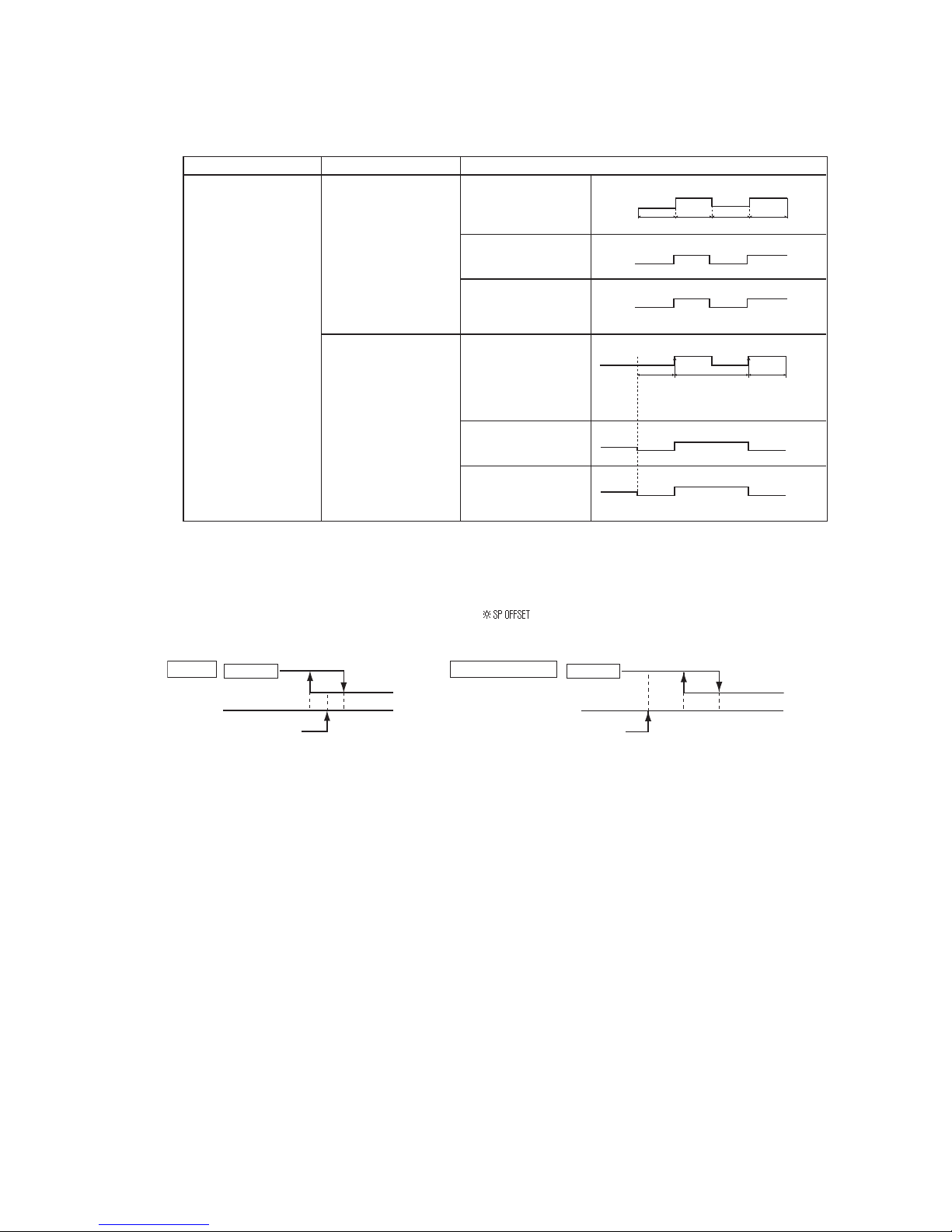
– 20 –
'14 • KX-SM-202
(d) If the cooling/heating selection signal is given by the external input, the operation mode is transmitted to the remote
control.
■
Selection of cooling/heating external input function
Notes (1) Regarding the priority order for combinations of CnT and CnTA, refer to Page 16.
External input selection
External input selection
Cooling/heating selection
External input method
⑤ Level
External terminal input
(CnT or CnTA)
Cooling/heating
Cooling/heating
(Competitive)
External terminal input
(CnT or CnTA)
Cooling/heating
Cooling/heating
(Competitive)
⑥Pulse
Operation
OFF
Cooling zone
Heating zone Cooling zone
Cooling zoneHeating zone Heating zone
OFF
ON
OFFOFF
ON ON
ON
Cooling
Heating Heating
Cooling
Cooling
Cooling
Auto
Auto
Cooling
Auto, cooling, dry mode↑
command from remote control
↑Heating, auto, heating mode
command from remote control
↑Set “Cooling/
Heating” “Pulse”
↑Auto, cooling, dry mode
command by remote control
↑Auto, heating mode
command by remote control
↑After setting “Cooling/heating selection”, the cooling/heating is
selected by the current operation mode.
During heating:: Set at the heating zone (cooling prohibition zone).
During cooling, dry, auto and fan mode: Set
at cooling zone (heating prohibition zone).
Heating
Heating
Heating
Cooling
Heating
Cooling
Cooling
(21) Room temperature detection temperature compensation during heating
Withthestandardspecication,thecompressoristurnedON/OFFwiththethermostatsettingtemperature.Whenthethermostat
is likely to turn OFF earlier because the unit is installed at the ceiling where warm air tends to accumulate, the setting can be
changed with the wired remote control indoor unit function “ ”. The compressor and the heater are turned ON/OFF at
one of the setting temperature +3, +2 or +1°C in order to improve the feeling of heating. The setting temperature, however, has
the upper limit of 30°C.
Compressor Compressor
Standard
Operation
Stop
Setting temperature
-1 +1
Room temperature (deg)
Operation
Stop
Setting temperature
+2 +4
Room temperature (deg)
When it is set at +3°C
(22) Return air temperature compensation
This is the function to compensate the deviation between the detection temperature by the return air temperature thermistor and
the measured temperature after installing the unit.
(a) It is adjustable in the unit of 0.5°C with the wired remote control indoor unit function “RETURN AIR TEMP”.
• +1.0°C, +1.5°C, +2.0°C • -1.0°C, -1.5°C, -2.0°C
(b) Compensated temperature is transmitted to the remote control and the compressor to control them.
Note (1) The detection temperature compensation is effective on the indoor unit thermistor only.
(23) High power operation (RC-EX1A only)
Itoperatesatwith the set temp. xed at 16°C for cooling, 30°C for heating and maximum indoor fan speed for 15 minutes
maximum.
(24) Energy-saving operation (RC-EX1A only)
It operates with the setting temperature fixed at 28°C for cooling, 22°C for heating or 25°C for auto. (Maximum capacity is
restricted at 80%.)
(25) Warm-up control (RC-EX1A only)
Operation will be started 5 to 60 minutes before use according to the forecast made by the microcomputer which calculates
when the operation should be started in order to warm up the indoor temperature near the setting temperature at the setting time
of operation start.
Page 23

– 21 –
'14 • KX-SM-202
(26) Home leave mode (RC-EX1A only)
When the unit is not used for a long period of time, the room temperature is maintained at a moderate leval, avoiding extremely
hot or cool temperature.
(a) Cooling or heating is operated according to the outdoor temperature (factory setting 35°C for cooling, 0°C for heating)
and the set temp. (factory setting 33°C for cooling, 10°C for heating
)
(b) Set temp and indoor fan speed can be set by RC-EX1A.
(27) Auto temp. setting (RC-EX1A only)
Setting temperature is adjusted automatically at the adequate temperature the center set temp. is 24°C by correcting the outdoor
air temperature.
(28) Fan circulator operation (RC-EX1A only)
When the fan is used for circulation, the unit is operated as follows depending on the setting with the remote control.
(a) If the invalid is selected with the remote control, the fan is operated continuously during the fan operation. (mormal fan
mode)
(b) If the valid is selected with the remote control, the fan is operated or stopped when on the difference of
the remote control
temperature sensor and the indoor unit return air temperature sensor becomes bigger than 3
°C.
(29) The operation judgment is executed every 5 minutes (RC-EX1A only)
Setting temperature Ts is changed according to outdoor temperature
This control is valid with cooling and heating mode. (NOT auto mode)
(a) Operate 5 minutes forcedly.
(b) Setting temperature is adjusted every 10 minutes.
(i) Cooling mode.
Ts = outdoor temperature - offset value
(ii) Heating mode.
Ts = outdoor temperature - offset value
(c)
If the return air temperature lower than 18°C or return air temperature becomes lower than 25°C, unit goes thermo OFF.
(30) Auto fan speed control (RC-EX1A only)
Inordertoreachtheroomtemperaturetothesettemperatureasquicklyaspossible,theairowrateisincreasedwhentheset
temperature of thermostat differs largely from the return air temperature. According to temperature difference be tureen set
temperature and return air temperature, indoor fan tap are controlled automalically.
・
Auto1:ChangestheindoorunitfantapwithintherangeofHi↔Me↔Lo.
・
Auto2:ChangestheindoorunitfantapwithintherangeofPHi↔Hi↔Me↔Lo.
(31) IU overload alarm (RC-EX1A only)
Ifthefollowingconditionissatisedat30minutesafterstartingoperation,RC-EX1Ashowsmaintenancecode"M07"andthe
signal is transmitted to the external output (CnT-5).
(a) Receipt of the signal by the external output is indicated by lighting an LED or other prepared on site.
・
Cooling, Dry, Auto(Cooling) : Indoor air temperature = Set room temperature by remote control + Alarm temperature difference
・
Heating, Auto(Heating)
: Indoor air temperature = Set room temperature by remote control - Alarm temperature difference
Alarm temperature difference is selectable between 5 to 10°C.
(b) If the following condition is satisfied or unit is stopped, the signal is disappeared.
・
Cooling, Dry, Auto(Cooling) : Indoor air temperature = Set room temperature + Alarm temperature difference -2
°C
・
Heating, Auto(Heating)
: Indoor air temperature = Set room temperature - Alarm temperature difference +2
°C
(32) Peak-cut time (RC-EX1A only)
Power consumption can be reduced by restricting the maximum capacity.
Set the [Start time], the [End time] and the capacity limit % (Peak-cut %).
・
4-operation patterns per day can be set at maximum.
・
The setting time can be changed by 5-minutes interval.
・
The selectable range of capacity limit % (Peak-cut %) is from 0% to 40-80% (20% interval)
.
・
Holiday setting is available.
Page 24
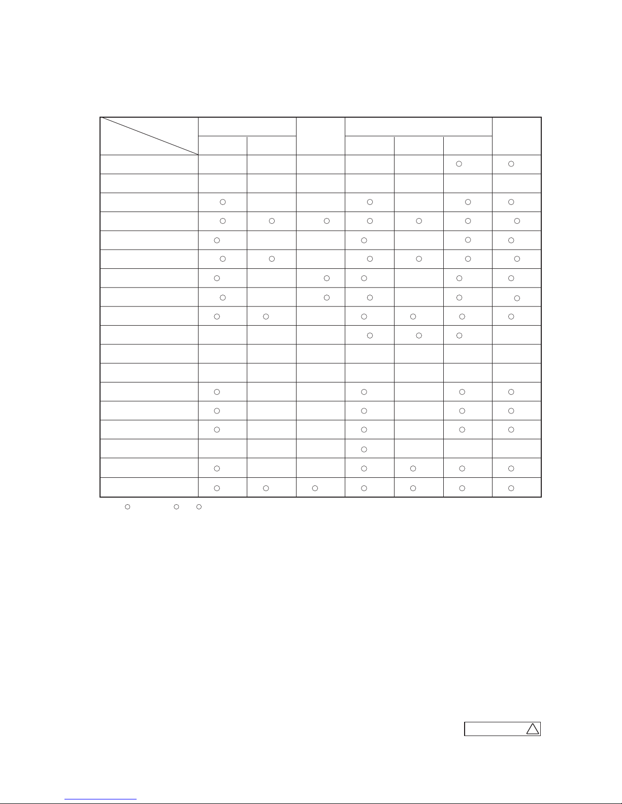
– 22 –
'14 • KX-SM-202
1.4 Operation control function by the outdoor control
(A) Normal control
(1) Operation of major functional components under each operation mode
Functional
Components
Indoor unit fan
Compressor [CM1]
Compressor [CM2]
Outdoor unit fan [FMo-1]
Outdoor unit fan [FMo-2]
4 way valve [20S]
Solenoid valve [SV6] [SV7]
Solenoid valve [SV11]
Electronic expansion valve
for heating [EEVH1, 2]
Electronic expansion valve
for sub-cooling [EEVSC]
Indoor unit electronic
expansion valve
Operation
mode
Cooling Heating
Defrost
Thermostat OFFThermostat ONThermostat OFFThermostat ON
Fan
Dehumidify
Remote control
command
Superheating
control response
Outlet temperature
control response
Superheating
Control Response
Fully closed Fully closed
Slight opening
control
Model-specific
aperture opening
angle
Fully open
※1
※3
Fully open
※3※4
Fully closed※2Fully closed Fully closed Fully closed Fully closed
※2
Superheating
control response
Opening pulse
control
Fully closed
/ Fully open
Opening pulse
control
Remote control
command
Remote control
command
Remote control
command
Intermittent
operation
→ /
/
/
→
→
→
/
/ /
/
/
/
/
Inverter cooling fan
[FMC1, 2]
/ / / / / /
/
/
/
/
/
Solenoid valve [20UF]
/ / / / /
Magnetic contactor CM1
[52X1]
/
Magnetic contactor CM2
[52X2]
Solenoid valve [SV1]
/ / / /
Solenoid valve [SV2]
/ / / /
Crankcase heater [CH1,2]
/ / / / / / /
Notes(1) : ON, : OFF, /, /: ON or OFF
(2) ※1: The EEVH1, 2 of master unit are fully opened and those of slave unit are fully closed.
(3) ※2: When the unit is stopped from cooling operation, the EEVH1, 2 of master unit are fully opened and those of slave unit are fully closed.
When the unit is stopped from heating operation, the EEVH1, 2 of both master and slave units are fully closed unless the opening degree is specified
by the low pressure protective control.
(4) ※3: When the operation mode is changed from heating to cooling/dehumidifying, EEVH1, 2 are maintained at fully closed position and EEV of only one
indoor unit keeps 60 pulse until 20S is turned OFF.
(5) ※4: When the operation mode is changed from cooling/dehumidifying to heating, EEVH1, 2 are maintained at fully opened position and EEVs of all
indoor units keep 0 pulse until 20S is turned ON.
(6) This shows the state of output when all indoor units are in the same operation mode.
F
ES P - FP-210 0
Page 25
– 23 –
'14 • KX-SM-202
(2) Compressor control (Master unit/slave unit)
(a) Starting compressor
(i) Compressor starting order
Afterturningthepoweron,rstlyCM1compressorstarts.(Incaseofthecombinationuse,itisCM01ofmasterunit)
And corresponding to the condition of under-dome temperature and to the required capacity of indoor units thermo-
statON,thenextcompressorwillstartsequentially,andnallymaximum6compressors(incaseof3outdoorunits
combination use) will start simultaneously.
1) Single use (Model 280, 335)
CM1
Range of the compressor operation speed relative to load is as follows.
System load range
(Number of operating outdoor units)
0
1
Local load range
(Number of compressors operating in outdoor units)
0 1
CM1
0rps 20−140rps
*
Note(1)
*
only model 355 is MAX 140rps, model 280 is MAX 120rps.
2) Single use (Model 400, 450)
CM1
Range of the compressor operation frequency relative to load is as follows.
System load range
0
1
Local load range
0 1
CM1
0rps 20−120rps
3) Single use (Model 475, 500, 560 : 2 compressors specification)
CM1 CM2
Range of the compressor operation frequency relative to load is as follows.
System load range
0
1
Local load range
0 1 2
CM1
0rps 20−112rps 31−120rps
CM2
0rps 0rps 31−120rps
4) 2 outdoor units combination use (Model 615, 670)
Master unit
Slave unit
CM01 CM11
(CM1)(CM1)
Range of the compressor operation frequency relative to load is as follows. Following table is applicable when CM01 starts initially.
System load range
0
1 1
Local load range
0 1 1
Master unit CM01
0rps 20−112rps 31−120rps
Slave unit CM11
0rps 0rps 31−120rps
Page 26
– 24 –
'14 • KX-SM-202
5) 2 outdoor units combination use (Model 735)
Model 400 (Master) + 335 (Slave)
Master unit Slave unit
CM01 CM11
(CM1)(CM1)
Range of the compressor operation speed relative to load is as follows. Following table is applicable when CM01 starts initially.
System load range
0
1 2
Local load range
0 1 1
Master unit CM01
0rps 20−112rps 52−120rps
Slave unit CM11
0rps 0rps 31−70rps
Model 335 (Master) + 400 (Slave)
Master unit Slave unit
CM01 CM11
(CM1)(CM1)
Range of the compressor operation speed relative to load is as follows. Following table is applicable when CM01 starts initially.
System load range
0
1 2
Local load range
0 1 1
Master unit CM01
0rps 21−65rps 31−70rps
Slave unit CM11
0rps 0rps 52−120rps
6) 2 outdoor units combination use (Model 800, 850, 900)
Master unit
Slave unit
CM01 CM11
(CM1)(CM1)
Range of the compressor operation speed relative to load is as follows. Following table is applicable when CM01 starts initially.
System load range
0
1 2
Local load range
0 1 1
Master unit CM01
0rps 20−65rps 31−120rps
Slave unit CM11
0rps 0rps 31−120rps
7) 2 outdoor units combination use (Model 950, 1000, 1060, 1120)
Master unit
Slave unit
CM01 CM11
(CM1)(CM1)
CM02 CM12
(CM2)(CM2)
Range of the compressor operation speed relative to load is as follows. Following table is applicable when CM01 starts initially.
System load range
0
1 2
Local load range
0 1 1 2
Master
unit
CM01
0rps 20−112rps 31−112rps 31−120rps
CM02
0rps 0rps 0rps 31−120rps
Slave
unit
CM11
0rps 0rps 31−112rps 31−120rps
CM12
0rps 0rps 0rps 31−120rps
Page 27
– 25 –
'14 • KX-SM-202
9) 3 outdoor units combination use (Model 1200, 1250, 1300, 1350)
Master unit
Slave unit 1 Slave unit 2
CM01 CM11
(CM1)
CM21
(CM1)(CM1)
Range of the compressor operation speed relative to load is as follows. Following table is applicable when CM01 starts initially.
System load range
0
1 2 3
Local load range
0 1 1 1
Master unit CM01
0rps 20−112rps 31−65rps 31−120rps
Slave unit 1 CM11
0rps 0rps 31−65rps 31−120rps
Slave unit 2 CM21
0rps 0rps 0rps 31−120rps
10) 3 outdoor units combination use (Model 1425, 1450, 1500, 1560, 1620, 1680)
Master unit
Slave unit 1 Slave unit 2
CM01 CM11
(CM1)(CM1)
CM02 CM12
(CM2)
CM21
(CM1)
CM22
(CM2)(CM2)
Range of the compressor operation speed relative to load is as follows. Following table is applicable when CM01 starts initially.
System load range
0
1 2 3
Local load range
0 0 1 1 2
Master
unit
CM01
0rps 20−112rps 31−112rps 31−112rps 31−120rps
CM02
0rps 0rps 0rps 0rps 31−120rps
Slave
unit 1
CM11
0rps 0rps 31−112rps 31−112rps 31−120rps
CM12
0rps 0rps 0rps 0rps 31−120rps
Slave
unit 2
CM21
0rps 0rps 0rps 31−112rps 31−120rps
CM22
0rps 0rps 0rps 0rps 31−120rps
(ii) Rotation of compressor start/stop order
1) The compressors will be changed over by determinating the start/stop order in each heat load zone.
2) In case of single use, the starting order of CM1 and CM2 will be changed over on each occasion when the out
-
door unit stops.
3) In case of combination use, the starting order of CM01(CM11)
〔
CM21〕 and CM02(CM12) 〔CM22
〕
will be
changed over on each occation when the master unit or slave unit stops all independently.
4) In case of combination use, the starting order of master and slave units will be changed over on each occasion
when the master unit or slave unit stops all independently.
Startingorderofoutdoorunits Master→Slave→Master
Page 28
– 26 –
'14 • KX-SM-202
(3) Outdoor fan control (Master unit/slave unit)
(a) Outdoor fan speed and fan motor rotation speed
Fan tap
Cooling Heating Remarks˝
FMo1 FMo2 FMo1 FMo2
0th speed 0 0 0 0 stop
1st speed 0 160 0 160
Min. speed at 1 FM operation
2nd speed 200 200 0 400
Max. speed at 1 FM operation
(During heating)
3rd speed 300 300 160 160
Min. speed at 2 FM operation
(During heating)
4th speed 400 400 1140 1140
Max. speed at 2 FM operation
(During heating)
Rated speed of heating
5th speed 500 500 − −
6th speed 600 600 − −
7th speed 700 700 − −
8th speed 800 800 − −
9th speed 900 900 − −
10th speed 1000 1000 − −
11th speed 1100 1100 − −
12th speed 1140 1140 − − Rated speed of cooling
(b) Outdoor fan control in cooling mode
Fan speed is controlled based on the high pressure during cooling/dehumidifying (detected with PSH) and the outdoor air
temperature (detected with Tho-A).
(i) Initial fan speed is as follows.
Initial cooling speed of outdoor fan
Outdoor temperature ≦ 10°C
10°C ≦ Outdoor temperature < 15°C
15°C
≦
Outdoor temperature
2nd speed 4th speed 6th speed
(ii) Speed changes depending on high pressure values.
(c)
Outdoor fan control in heating mode
Fan speed is controlled based on the low pressure (detected with PSL) during heating operation.
(i) Speed changes depending on low pressure values.
(ii) Under normal condition, the stepless fan control between 1st speed and 4th speed is performed.
Unit : min
-1
Page 29
– 27 –
'14 • KX-SM-202
(4) Defrosting (Master unit/Slave unit)
If the defrost starting conditions at the outdoor heat exchanger are established, defrost operation starts.
(a) Temperature conditions for defrosting
(i) Conditions for starting defrost
Whenalloffollowingconditionsaresatised,defrostoperationwillbestarted.
1) When the cumul ative operati on time
of the compressor becomes 33 minutes
afte r co mplet ion of previ ous defro st
operation, or it becomes 33 minutes after
heating operation starts.
2) When 8 minutes have elapsed after one
compressor is turned ON from the state
of all compressors OFF.
3) When 8 minutes have elapsed after one
outdoor fan is turned ON from the state
of all outdoor fan OFF.
4) Wheneitheroffollowingconditionsisestablishedafteralloftheaboveconditionsaresatised.
•
When the temperatures detected with the outdoor heat exchanger temperature thermistor (Tho-R1,-R2) and
outdoor air temperature thermistor (Tho-A) are below the defrost starting temperature mentioned in the above
graph continuously for 3 minutes.
•
When t he suction pressure saturation
temperature has continued for 3 minutes
in the defrost zone which is determined
by the outdoor air temperature sensor
(Fig. 2)
(ii) Conditions for finishing defrost
• Standard (J14 is shorted)
1) When the temperature detected with both outdoor heat exchanger temperature thermistors (Tho-R1 and
Tho-R2) is higher than 9ºC
2) Or when 12 minutes have elapsed since defrosting started.
• Cold region setting (J14 is open)
1) When (Tho-R1 and Tho-R2)
>
=
9ºC is satised,after2 minutes and30secondshave elapsedsincedefrosting
started,andwheneitheroffollowingconditionsissatised,thedefrostingendoperationstarts.
a) 2 minutes and 30 seconds have elapsed since the temperature of either Tho-R1 or Tho-R2 was 14ºC or
higher
b) The temperature of either Tho-R1 or Tho-R2 is 30ºC or higher.
c) 14 minutes have elapsed since defrosting started.
2) When (Tho-R1andTho-R2)<9ºCissatised,after2minutesand30secondshaveelapsedsincedefrosting
started,andwheneitheroffollowingconditionsissatised,thedefrostingendoperationstarts.
a) 5 minutes have elapsed since the temperature of either Tho-R1 or Tho-R2 was 14ºC or higher.
b) The temperature of either Tho-R1 or Tho-R2 is 30ºC or higher.
c) 14 minutes have elapsed since defrosting started.
-20 -15 6
J15 opened
Cold region
specification
J15 shorted
Outdoor air temp. (ºC) [Tho-A]
Cold region
Defrost start zone
Standard
(Factory setting)
Heat exchanger temp. (°C) [Tho-R]
Fig.1
-2
-6
-15
-19
-21
-25
-20
-15 6
J15 opened
Cold region
specification
J15 shorted
Outdoor air temp. (ºC) [Tho-A]
Cold region
Defrost start zone
Standard
(Factory setting)
5WEVKQPRTGUUWTGUCVWTCVKQPVGORGTCVWTG°C
Fig.2
-6
-10
-19
-23
-25
-29
Page 30
– 28 –
'14 • KX-SM-202
(5) Protective control
(a) High pressure protective control/error
If the high pressure exceeds 3.7 MPa, the compressor speed is reduced gradually.
It reduces to 20 rps at the lowest.
If the high pressure still rises to 4.15 MPa, the compressor stops.
(b)
Low pressure protective control/error
If the low pressure drops below 0.18 MPa, the compressor speed is reduced gradually.
It reduces to 20 rps at the lowest.
If the low pressure still drops below 0.134 MPa, the compressor stops.
(c)
Discharge pipe temperature control/error
If discharge pipe temperatures (detected with Tho-D1, -D2) exceed 120ºC, the compressor speed is reduced gradually. (To 20
rps at the lowest) If the temperatures still continue to rise beyond 130ºC, the compressor stops.
(d) Compressor compression ratio protective control
If the compressor compression ratio exceeds the setting value, the compressor speed is reduced gradually.
It reduces to 20 rps at the lowest.
(e)
Current safe control
(i) The current safe control monitors current values at T-phase of inverter. If the value exceeds the setting value, the com
-
pressor speed is reduced.
If the value is higher than the setting value even if the speed is reduced, the speed is reduced further.
(ii) This control is reset if the current value at T-phase of inverter becomes lower than the setting value – 1 A for 3 minutes
continuously or lower than the setting value for 6 minutes continuously.
(f)
Current cut control
(i) Current sensor built in the power transistor monitors current values output from the inverter. If the value exceeds 88 A,
the current cut control stops the compressor. The compressor starts automatically 3 minutes after the stop.
(ii) If the above control activates 4 times within 15 minutes, 52C1 or 52C2 is turned off, and the operation is stopped with
the error stop.
State of the error continues for 3 minutes after the error stop. The error can be reset by operating the inspection reset
from the remote control.
(g)
Power transistor temperature (PT) protective control
If temperatures on the power transistor exceed the setting value, the compressor speed is reduced gradually.
It reduces to 20 rps at the lowest.
(h)
Under-dome temperature protective control
If the under-dome temperature exceeds the setting value, the compressor speed is reduced gradually.
It reduces to 20 rps at the lowest.
(i) Protection for combination of outdoor units (Master unit)
The capacity of connectable outdoor units is checked when the communication check is performed after turning the power ON.
If the checked result is other than the allowable combinations mentioned in the following table ① it is prohibited to start
operation due to outdoor unit combination error.
When this error occurs, the error code mentioned in the following table
②
is displayed on the 7-segment display.
Table②Contents displayed on 7-segment display at the combination error
Table①combination list
Code display area Data display area Contents of invalid operation
3OPE
Invalid combination of outdoor units
Capacity
615
670
735
800
850
900
950
1000
1060
1120
Combination patterns
Combination(280+335)
Combination(335+335)
Combination(335+400)
Combination(400+400)
Combination(400+450)
Combination(450+450)
Combination(475+475)
Combination(500+500)
Combination(500+560)
Combination(560+560)
Capacity
1200
1250
1300
1350
1425
1450
1500
1560
1620
1680
Combination patterns
Combination(400+400+400)
Combination(400+400+450)
Combination(400+450+450)
Combination(450+450+450)
Combination(475+475+475)
Combination(475+475+500)
Combination(500+500+500)
Combination(500+500+560)
Combination(500+560+560)
Combination(560+560+560)
Page 31

– 29 –
'14 • KX-SM-202
(6) Auto backup operation
(a) Classi cation of auto backup operations
When the auto backup operation is enabled, anomaly stops are classifiedas follows and countermeasures are provided for
respective categories.
System stop: All stop including master/slave units
Unit stop: Stop in the unit of outdoor unit
Compressor stop: Stop in the unit of compressor
(b) Control contents of auto backup operation
(i) Condition of auto backup operation is established when the dip switch SW3-2 on the PCB of master unit is turned
ON (selected).
(ii) However, the switching of SW3-2 is effective only at the power on. (It does not become effective unless the power
supply is reset.)
(iii)
Anomaly contents in the following table are invalid and are not detected when the auto backup is effective.
Anomaly detection invalid code SW3-2ON Anomaly detection invalid code SW3-2ON
E32: Open L3 phase on power supply at
primary side
E45: Communication error between inverter
PCB and outdoor control PCB
E36: Discharge pipe temperature error E48: Outdoor DC fan motor anomaly
E37: Outdoor heat exchanger and sub-cooling
coil temperature thernistor anomaly
E51: Power transister overheat
(Continuousness)
E38: Outdoor air temperature thermistor
anomaly
E53: Suction pipe temperature thermistor
anomaly
E55: Under-dome temperature thermistor
anomaly
E39: Discharge pipe temperature thermistor
anomaly
E40: High pressure anomaly
E56: Power transitor temperature thermistor
anomaly
○
○
○
○
○
○
○
○
○
○
○
○
E41: Power transister overheat
E58: Anomalous compressor by loss
synchronism
E42: Current cut
E44: Liquid flooding anomaly
E59: Compressor startup failure
E60: Rotor position detection failure
○
○
○
○
○
○
(iv)Ifanyanomalyoccurswhentheautobackupiseffective,theoperationoutput(CnH),Anomalyoutput(CnY),7-seg-
ment display and LED show as follows.
1) At the system stop
Operation output on the master unit is turned OFF, the Anomaly output is turned ON, 7-segment display and
LED show the anomaly, and the remote control displays E??. (To reset the anomaly, it is necessary to reset the
inspection from the remote control.)
2) At the unit stop
On the anomaly occurred unit only, the operation output is turned OFF, the Anomaly output is turned ON, 7-segment
display and LED show the anomaly and normal units continue their operation ON(or stop).
To reset the state of anomaly on the unit the anomaly occurred, it depends on the condition to reset the state of each anomaly.
3) At the compressor stop
Only the compressor concerned stops, previous states are maintained on the operation output, anomaly output,
7-segment display and LED. To reset the state of anomaly on the compressor, it depends on the condition to reset
the state of each anomaly.
Page 32

– 30 –
'14 • KX-SM-202
E31
E32
E36
E37
E38
E39
E40
E41
E42
E43
E44
Duplicated outdoor unit address No.
Open L3 Phase on power supply at primary side
Discharge pipe temperature error
Outdoor air temperature thermistor anomaly
Discharge pipe temperature thermistor anomaly
High pressure anomaly
Power thansistor overheat
Current cut
Anomaly contents
Anomalous stop of master outdoor unit Anomalous stop of slave outdoor unit
System stop Unit stop
Compressor stop
System stop Unit stop
Compressor stop
Remote control
error display
Outdoor heat exchanger and subcooling
coil temperature thermistor anomaly
Liquid flooding anomaly
Excessive number of indoor unit connected,
excessive to tal capacity of connection
E45
E48
E49
E51
E53
E54
E55
E56
E59
E60
E61
E63
Outdoor DC fan motor anomaly
Low pressure error
Suction pipe temperature thermistor anomaly
Under-dome temperature thermistor anomaly
Power transitor temperture thermistor anomaly
Compressor startup failure
Rotor position detection failure
Emergency stop
Communication error between inverter
PCB and outdoor control PCB
High pressure sensor/Low pressure
sensor anomaly
Power transister overheat (continuousness)
Communications error between the master
unit and slave units
Backup operation function is only for emergency purpose when one of compressors or one of units is damaged.
If backup operation is performed continuously for long period, it may cause the damage of good compressors.
Accordingly be sure to repair the damaged unit or to replace the damaged compressor and to cancel the
backup operation within 48 hours after starting backup operation.
(c) Prohibiting conditions of auto backup operation
(i) When the conditions of oil return control are not established
(ii)
When the backup operation time has exceeded the limit value
(d) Control after the conditions to prohibit the auto backup operation have been established
All compressor stop, and the error display [E-XX] is shown on the 7-segment display and the remote control.
In this state, the inspection reset of remote control is effective. → [E-XX] is displayed continuously on the remote con-
In this state, the inspection reset of remote control is effective. → [E-XX] is displayed continuously on the remote control.
E45
E48
E49
E51
E53
E54
E55
E56
E59
E60
E61
E63
Outdoor DC fan motor anomaly
Low pressure error
Suction pipe temperature thermistor anomaly
Under-dome temperature thermistor anomaly
Power transitor temperture thermistor anomaly
Compressor startup failure
Rotor position detection failure
Emergency stop
Communication error between inverter
PCB and outdoor control PCB
High pressure sensor/Low pressure
sensor anomaly
Power transister overheat (continuousness)
Communications error between the master
unit and slave units
Backup operation function is only for emergency purpose when one of compressors or one of units is damaged.
If backup operation is performed continuously for long period, it may cause the damage of good compressors.
Accordingly be sure to repair the damaged unit or to replace the damaged compressor and to cancel the backup operation
within 48 hours after starting backup operation.
(c) Prohibiting conditions of auto backup operation
(i) When the conditions of oil return control are not established
(ii) When the backup operation time has exceeded the limit value
(d) Control after the conditions to prohibit the auto backup operation have been established
All compressor stop, and the error display [E-XX] is shown on the 7-segment display and the remote control.
trol.
Page 33

– 31 –
'14 • KX-SM-202
(7) Test run
(a) This control can be performed from the master unit, not from the slave unit.
If this control is done from the slave unit, the following display is shown on the 7-segement display.
The display returns to normal display if the test run control switch is reset.
(b) Test run from master outdoor units with dip switches SW5-1 and SW5-2.
Take note that this operation has priority over other option devices such as center console and etc.
This operation status is transmitted to the option devices.
(Note) Test run operation by external input is also available with following method. (Refer next page for detail)
• Select the external input terminal (CnS1) and set 7-segment [P11]-[6] for the function of SW5-1, and select the external input terminal (CnS2) and
set 7-segment [P12]-[7] for the function of SW5-2.
• Other combination of external input terminals (CnS1, CnS2, CnG1, CnG2) and of setting function with 7-segment ([P11], [P12], [P13], [P14] and
-[6], -[7]) are avilable to use.
(c) Starting conditions of test run operation
(i) Dip switch SW5-1 is turned ON. However the input before the power ON is invalid.
(ii) The dip switches SW3 and SW5, other than SW5-1and SW5-2, should be turned OFF.
However, regarding the dip switch SW3-2 for automatic backup operation, it is invalid during test run operation
regardlesswhetherSW3-2isturnedON(valid)orOFF(invalid).→Inordertochecktroubleduringtestrunoperation.
(d) Control during test run (If indoor units are normal)
(i) Heating operation is performed with SW5-2 OFF, while cooling operation is performed with SW5-2 ON.
(ii) IndoorEEVcontrolattheendoftestrunisdependedonthespecicationsoftheindoorunit.
(iii)
Cooling operation: Compressor frequency control is depended on the cooling low pressure control.
(iv) Heating operation: Compressor frequency control is depended on the heating high pressure control.
(e) Ending conditions of test run operation
Testrunoperationisterminatedifoneoffollowingconditionsissatised.
(i) Test run operation ends when the dip switch SW5-1 is turned OFF.
(ii)
When the operation is stopped by the error control during test run, the error is displayed same as the normal operation
and the state of error stop is retained even if SW5-1 is turned OFF.
Code indicator Data indicator Contents of invalid operation
10OPE
Slave setting is invalid.
ON
SW5-1
SW5-2
OFF
ON
OFF
Test run for heating
Test run for cooling
Normally operation and after test operation
CnS1
Shorted CnS2
Open Test run for heating
Shorted Test run for cooling
Open
Normal operation and after test operation
Page 34

-
32
-
(1) External input and demand input (Master unit/Slave unit)
(a) Operation permission or prohibition mode
(Note) Following explanation is based on using CnS1 terminal and setting function [P07]-[0] with 7-segment display.
However other terminals can be used with following function setting of 7-segment display.
CnS2: [P08]-[0] CnG1: [P09]-[0] CnG2: [P10]-[0]
1) Operation permission or prohibition mode is switched with the connector (CnS1) and the Jumper wire (J13) on
the outdoor control PCB after setting function [P07]-[0] (Factory setting) with 7-segment display
2) Operation permission/prohibition control by the external input CnS1 to outdoor unit.
Note (1) Factory setting J13: Shorted, CnS1: Shorted (Short pin is connected)
(B) Option controls
• External input terminal
①
4 External input terminals (CnS1, CnS2, CnG1 and CnG2) are provided. (See Fig-1)
②
Each external input terminal can be changed its function by allotting the external input function No. of P07-P10 selected
with 7-segment respectively. (External input functions of the code P07-P10 are shown in Fig-2)
③
The following function is effective, when the external input function of PXX-"X" is allotted and the signal is input to the
external terminal of CnXX.
(Example) If CnS1 terminal is used for demand control (pulse input), allot the "1" of P07 and open J13, and if CnS2 terminal is
used for demand control (level input), allot the "1" of P08 and short J13.
④
J13: Switching of CnS1,S2 input method (CnS1, S2 only)
J13 shorted: Level input by CnS1, S2
J13 open : Pulse input by CnS1, S2
*1 "Setting" means;
Master : Set only the master unit. (No necessary to set the slave unit)
Master/Slave: Set both master/slave unit same.
External input terminal External input function allotment of 7-segment
Terminal Specication Factory setting Code Function No. Factory setting
CnS1 No voltage contact (DC12V) Shorted P07 "0"-"9" "0"
CnS2 No voltage contact (DC12V) Shorted P08 "0"-"9" "1"
CnG1 No voltage contact (DC12V) Open P09 "0"-"9" "2"
CnG2 No voltage contact (DC12V) Open P10 "0"-"9" "3"
Fig-1
The switch will continuously change the display indication to the next one in every 0.25 seconds when it is pressed for 0.75 seconds or longer.
If the Reset switch is pressed during an operation, the display indication returns to the one that was shown before the last Set switch operation.
Even if an indoor unit No. is changed in this mode, the registered indoor unit No. before address change mode is displayed when [I/U SELECTION
▼] is shown.
When “SET COMPLETE” is shown, indoor unit No.’s are registered.
Selecting an indoor unit
to be changed address
Setting a new indoor unit No.
2
3
Setting a new outdoor unit No.
Ending the session
4
5
④ Pressing the switch will change the display indication cyclically to show the unit No.’s
of the indoor units connected to the remote control and the unit No.’s of the outdoor units
connected with them.
⑤ Then the address No. of the indoor unit to be changed is determined and the screen switches to the
display “ SET I/U ADD.”
⑥ Set a new indoor unit No. with the switch.
A number indicated on the display will increase or decrease by 1 upon pressing the ▲ or ▼ switch
respectively.
⑦
After selecting an address, press the
SET
switch. Then the address No.of the indoor unit is determined.
⑧ The display will indicate the determined indoor address No. for 2 seconds and then switch to the
“ SET O/U ADD.” screen.
A default value shown on the display is the current address.
⑨ Set a new outdoor unit No. with the switch.
A number indicated on the display will increase or decrease by 1 upon pressing the ▲ or ▼ switch
respectively.
⑩ After selecting an address, press the SET switch.
Then the address of the indoor unit and outdoor unit are determined.
⑪ If you want to continue to change addresses, return to step ④.
⑫ If you want to end the session (and reflect new address settings)
In Step ⑩, press the ▼ switch to select “END ▲.”
If you have finished changing addresses, press the SET switch while “END ▲” is shown. While new
settings are being transmitted, “SET COMPLETE” will be indicated. Then the remote control display will
change to the normal state.
⑬ If you want to end the session (without reflecting new address settings)
Before you complete the present address setting session, press the “ON/OFF” switch.
Then the display is change to exit from this mode and switch the display to the normal state.
All address settings changed in the session will be aborted and not reflected.
[I/U002](2sec)
[I/U 002](2sec lighting)
⇔[SET O/U ADD.](1sec)
⇔[O/U01 ](Blink)
[O/U 00▲]
⇔[O/U 01 ]
⇔[O/U 02 ]
⇔ ・・・
⇔[O/U 31▼]
[I/U 002 O/U 02](2sec lighting)
→[SELECT](1sec lighting)
→[I/U SELECTION▼](lighting)
[Press the switch](1sec)
→[SET COMPLETE](2〜10sec
lighting)
[END▲]
→[SET COMPLETE](2〜10sec lighting)
→Normal state
[ON/OFF]
→Forced termination
[I/U 001 O/U 01▲」
⇔[I/U 002O/U 01 ]
⇔[I/U 003O/U 01 ]
⇔ ・・・
⇔[I/U 016 O/U 01▼」
[SET I/U ADD.](1sec)
→[I/U 001 ](Blink)
[I/U000▲]
⇔[I/U001 ]
⇔[I/U002 ]
⇔ ・・・
⇔[I/U127▼]
Turn on power to centralized control equipment after the addresses are determined.
Turning on power in wrong order may result in a failure to recognize addresses.
NOTICE
7 segment display indication in automatic address setting
Code Contents of a display
P30
P31
P32
P34
Code
Contents of a display
Items that are to be set by the customer
Communication protocol 0: Previous SL mode
1: New SL mode
Polarity difinition 0: Network polarity not defined.
1: Network polarity defined.
AUX
During automatic address setting.
X: The number of indoor units recognized by the outdoor unit.
AUE
Indoor unit address setting is completed normally.
End
Polarity is defined. (Automatic address)
Completed normally.
Automatic address start
Input starting address Specify a starting indoor unit address in automatic address setting.
(The communication plotocol is displayed ; display only)
P33
Input number of connected indoor units Specify the number of indoor units connected in the refrigerant system in automatic address setting.
7 segment display indication in automatic address setting.
*1 Valid/invalid is changed depending on outdoor temperatures.
*2 It is always Valid, regardless of outdoor temperature.
*3 According to the demand setting table.
“0” : External operation input
“1” : Demand input
“2” : Cooling / heating force input
“3” : Silent mode 1 *1
“4” : Spare
“5” : Outdoor fan snow control input
“6” : Test run external input 1 (SW5-1 equivalent)
“7” : Test run external input (SW5-2 equivalent)
“8” : Silent mode 2 *1
“9” : Demand input
“10” : AF periodic inspection display
“11” : AF error display
“12” : Building multi energy save control
Permitted
*3
Heating
Valid
Valid
Test run start
Cooling
Valid
*3
Valid
Valid
Valid
Prohibited
*3
Cooling
Invalid
Invalid
Normal
Heating
Invalid
*3
Invalid
Invalid
Invalid
By changing the allocation of external input function (P07-10) on the 7-segment, functions of external input terminal
may be selected. Inputting signals to external input terminals enable the following functions.
Demand
control
Function
assignment 1
Function
assignment 9
None (Normal)
1-step
2-step
3-step
Shorted
Open
Open
Shorted
Shorted
Shorted
Open
Open
*3 Demand setting table
Setting value for external input function assignment External input terminal shorted External input terminal open
Fig-2
'14 • KX-SM-202
Input: CnS1
Switching CnS1
input method:J13
CnS1: Switching operation
permission/prohibition mode
Shorted (Level input)
Shorted
Shorted
Open
Open
Operation prohibition mode
Operation permission mode
Operation permission mode
Operation prohibition mode
—
(NOP)
Switching operation permission/
Operation prohibition mode (Reversal)
Shorted (Level input)
Open (Pulse input)
Open (Pulse input)
Page 35

-
33
-
(b) Demand control
(Note) Following explanation is based on using CnS2 terminal and setting function [P08]-[1] with 7-segment display.
However other terminals can be used with following function setting of 7-segment display
CnS1: [P07]-[1] CnG1: [P09]-[1] CnG2: [P10]-[1]
1) Demand control or normal control is switched with the connector (CnS2) and the jumper wire (J13) on the outdoor
control PCB after setting function [P08]-[1] (Factory setting) with 7-segment display.
J13: Switching of CnS2 input method
J13 shorted: Level input by CnS2
J13 open : Pulse input by CnS2
2) Demand control/Normal operation by the external input CnS2 to outdoor unit.
Note (1) Factory setting J13: Shorted, CnS2: Shorted (Short pin is connected)
3) The operation condition is displayed on the LCD of remote control and it is transferred to option centralized control.
①
J13 − Shorted
②
J13 - Open
5) CnS1 performs the following operation according to switching the jumper wire (J13) shorted or open. In case of
pulse input, the pulse width is 500ms or larger.
PUSH
CnS1 input OFF (Open)
Remote control operation
Remote control display
Air-conditioner operation/stop
PUSH PUSH PUSH
OFF
Center Remote
ON (Shorted)
Center
OFF
OFF (Open)
Air-conditioner ON OK
OFF ONON
OFF OFF ONON
Remote control operation
Remote control display
Air-conditioner operation/stop
Center Center Center
Remote
Remote
Air-conditioner ON OK
CnS1 input
OFF
OFF
ON
ON OFF OFFON
OFFON
PUSH PUSH PUSH PUSH PUSH
Input: CnS2
Switching CnS2
input method:J13
CnS2: Switching operation
permission/prohibition mode
Shorted (Level input)
Shorted
Shorted
Open
Open
Demand control
Normal operation
Normal control
Demand operation
—
(NOP)
Switching Demand control/
Normal operation (Reversal)
Shorted (Level input)
Open (Pulse input)
Open (Pulse input)
'14 • KX-SM-202
OFF ON OFF OFFON
3)
The operation condition is displayed on the LCD of remote control and it is transferred to option centralized control.
4) When the operation command from remote control is not accepted by this control, "Center" is displayed on the
LCD of remote control. (See item 5 mentioned next page.)
6) After changing mode from operation prohibition mode to permission mode, the indoor units operation status can be
select by 7-segment [P17] setting.
7-segment [P17] =0 → Keeping STOP
7-segment [P17] =1 → Automatically RUN
'14 • KX-SM-202
Page 36

-
34
-
5)
4) Demand control
Demand ratio can be changed with the 7-segment "P04" on the outdoor control PCB.
P04 setting
Compressor
output (%)
080(Factory default)
80
060 60
040 40
000 0
6) CnS2 performs the following operation according to switching the jumper wire (J13) shorted or open.
In case of pulse input, the pulse width is 500ms or larger.
①
J13 − Shorted
②
J13 - Open
PUSH
CnS2 input
OFF OFF
ONON
Compressor
Compressor Demand
PUSH PUSH PUSH
Remote control operation
Remote control display
Air-conditioner operation/stop
Remote
ON (Shorted) ON (Open) ON (Shorted)
Demand control
NormalNormal
CnS2 input
Compressor
Compressor Demand
Remote control operation
Remote control display
Air-conditioner operation/stop
Remote
Demand control Demand control
OFFOFF
ONON
PUSH PUSH PUSH PUSH
(c) 3 step demand control
'14 • KX-SM-202
OFF OFF
ONON
Demand
OFF OFF
ONON
ONON
OFF OFF
Demand
This control has priority over the controls of 4-way valve safeguard, compressor protective start operation, defrost
operation, oil equalized operation, oil return operation, pump-down operation for replacement, Start/Stop pump-down
operation and check operation.
1) Starting condition
When the “Demand input 2” via the external input terminal of outdoor unit (master unit) has become valid.
2) Contents of control
The demand control is performed at the demand rate which has been set with [P14] and [P15] according to the de-
mand input or the demand input 2.
Demand control
Following is assigned to one of P07 - P10.
Demand rate
setting
Demand input
(Function assignment: 1)
Demand input 2
(Function assignment: 9)
None (Normal) Shorted Shorted ─
1st step demand Open Shorted P04
2nd step demand Open Open P14
3rd step demand Shorted Open P15
'14 • KX-SM-202
Page 37

-
35
-
PUSH
Demand input 2
OFF OFF
ON
ON
PUSH PUSH PUSH
Remote control operation
Remote control display
Air-conditioner operation/stop
Remote
Demand control
NormalNormal
.;60
OFF OFF
ONON
Demand control
Demand control
demand demand demand demand demand demand
1st step 1st step 2nd step 3rd step 2nd step 1st step
Normal Normal
Demand input
(CnS1,S2,G1,G2)
(CnS1,S2,G1,G2)
Valid(Open)
Invalid(Shorted)
Valid(Open)
Invalid(Shorted)
NormalNormal
3) Ending condition
When the starting conditions have been lost.
(d) Demand control from indoor unit
1) Starting condition
①
When a demand ratio (“80%”, “60%”, “40%” or “0%”) has been transmitted from an indoor unit of “Peak-cut
timer” function.
②
Normal demand of Item (b) is not activated.
③
This control is performed on the RC-EX1A remote control.
2) Contents of control
①
Compressor’s upper limit speed is restricted according to the demand restriction rate.
②
The demand ratio controlled by the restriction rate which is transmitted from an indoor unit.
③
If the demand control rate signals are received from two or more indoor units, the control takes the lowest rate.
④
When the demand rate is other than 0%, this control is superseded by the controls of 4-way valve safeguard, de-
frost operation, oil return operation, oil equalized operation, pump-down operation for replacement, Start/Stop
pump-down operation and check operation.
3) Ending condition
When the starting conditions have been lost.
'14 • KX-SM-202
Page 38

-
36
-
(2) Silent mode control
(Note) With CnG2 terminal and 7-segment display [P10]-[3] for silent mode 1(Factory default) or with CnG2 terminal and 7-segment display [P10]-[8]
for silent mode 2 (Setting on site) It is also avilable to use other terminals as follows.
CnS2: [P08]-[3] or -[8] CnS1: [P07]-[3] or -[8] CnG1: [P09]-[3] or -[8]
(a) Silent mode is commanded either from the indoor unit (remore control setting) or from the master outdoor unit (CnG2).
(b) When the "Silent mode start" signals is received from one of indoor units, it enters the silent mode operation.
(c) When CnG2 of master unit is shorted after setting function [P10]-[3] (Silent mode 1) or [P10]-[8] (Silent mode 2) with
7-segment display, it enters the silent mode operation. (If the signal is input to the slave unit, it is invalid)
(Note) Silent mode 1 and 2 can not be set at same time
(Note) In case of external input of silent mode 2, following temperature conditions are disregarded.
(d) When the "Silent mode start" signal from indoor unit and the "Silent mode" signal from outdoor unit are received, it enters
the silent mode operation under "or"condition.
(e) When silent mode signals from all indoor units become "Silent
mode end" and when silent mode signal input to CnG2 on
outdoor unit becomes open, the silent mode operation is reset.
(f) The operation of silent mode 1 is effective within the following temperature range.
• Cooling • Heating
Outdoor air temperature Outdoor air temperature
(i) Silent mode 0,1 : Effect on field A,B
(g)
Silent mode setting
Silent mode setting can be changed with 7-segment “P05” on the outdoor control PCB.
(ii) Silent mode 2,3 : Effect on field B
Valid (Field B)
Valid (Field A)
Invalid
29 31°C27
Valid (Field A)
Valid (Field B)
Invalid
2 4 6°C
P05 setting
000 (Factry default)
001
002
003
Silent mode setting
Silent mode setting 0
Silent mode setting 1
Silent mode setting 2
Silent mode setting 3
(h) Sound level (Reference data)
Model
SPL
Sound
pressure level
for cooling
SPL
Sound
pressure level
for heating
SPL
Silent
mode
setting 0
SPL
Silent
mode
setting 1
SPL
Silent
mode
setting 2
SPL
Silent
mode
setting 3
PWL
Cooling
PWL
Heating
(dB(A)) (dB(A)) (dB(A)) (dB(A)) (dB(A)) (dB(A)) (dB(A)) (dB(A))
FDC(S)280KXZE1
55 57 55 51 47 43 75 76
FDC(S)335KXZE1
61 58 61 57 53 49 81 78
FDC(S)400KXZE1
60 62 60 56 52 48 81 83
FDC(S)450KXZE1
61 62 61 57 53 49 81 83
FDC(S)475KXZE1
61 62 61 57 53 49 81 83
FDC(S)500KXZE1
61 62 61 57 53 49 81 83
FDC(S)560KXZE1
64 66 64 60 56 52 84 86
'14 • KX-SM-202
Page 39

-
37
-
(3) Outdoor fan snow protection control (Master unit/Slave unit)
(Note) Following explanation is based on setting function with 7-segment display [P02].
However the following terminals and 7-segment function settings are available to use.
CnS1: [P07]-[5] CnS2: [P08]-[5] CnG1: [P09]-[5] CnG2: [P10]-[5]
(a) The setting of this control should be done not only on the master unit but also on the slave unit, because the fans of master
unit and the slave unit are controlled independently.
(b) The control is enabled /disabled by selecting [0] or [1] displayed at 7-segment LED of master/slave units.
(c) Operation method of outdoor fan snow protection control
(i) Set the code [P02] on 7-segment display
(ii) “0” or “1” is displayed at the data display area of 7-segment LED.
“0”: Outdoor fan snow protection control is disabled (Factory setting)
“1”: Outdoor fan snow protection control is enabled
(iii) Press SW7 (Data write/delete) for 3 seconds continuously
(iv) “0” or “1” blinks every 0.5 second at the data display area of 7-segment LED.
(v) Press SW8 (one digit) to toggle the display between “0” and “1”.
(vi) If SW7 is pressed for 3 seconds continuously while “0” and “1” are blinking, “0” or “1” at the data display area of
7-segment LED stops blinking.
With this operation, the enabled/disabled setting of outdoor fan snow protection control is saved in the memory of
EEPROM, and henceforth the outdoor fan is controlled according to the contents of memory.
(vii) Contents of outdoor fan snow protection control are retained even if the power is turned off and backed on again.
(d) Contents of outdoor fan snow protection control
(i) At the status of all stop or emergency stop, if the outdoor air temperature drops 3°C or lower, all of outdoor fans are
operated at the maximum speed (4th speed) once every 10 minutes.
(ii) The outdoor fan runs for 30 minutes
(iii) During this snow protection control, the magnetic
contactor 52C1 of the compressor is ON
(4) Outdoor operation mode
On the standard models of 2 pipe system, the outdoor operation mode of Stop/Cooling/Heating is selected based on the informa-
tion of indoor units, and then respective controls are performed.
<Contents of control>
(a) Determination of outdoor operation mode
Operation mode of outdoor unit is determined based on respective signals of Operation/Stop and Cooling/Heating.
(b) Type of outdoor operation mode
1) Outdoor operation mode - Stop
2) Outdoor operation mode - Cooling
3) Outdoor operation mode - Heating
(c) Priority in operation mode selection.
1) First priority is given to the forced cooling/heating operation.
2) Second priority is given as follows
Priority in the operation mode selection can be changed using the 7-segment setting [P01].
3 5
Outdoor air temperature (°C)
Fan OFF
Fan ON
'14 • KX-SM-202
Page 40

-
38
-
・
First unit’s operation mode: Operation mode of the indoor unit which is operated rst time after stop of the outdoor
unit operation mode
・
Last unit’s operation mode: Operation mode of the indoor unit which is operated at the last time
・
Priority of master unit’s setting operation mode: Operation mode of indoor unit of which the address No. is small-
est (Master indoor unit). When the master indoor unit is turned off,
it become valid the rst push priority on other indoor units’ remote
controls.
・
Priority of required major operation mode: Operation mode of which the total capacity of operating indoor units is
larger. There is no renewed judgment for 10 minutes after a change on the
operation mode.
The judgment, however, is renewed in following cases.
-
At the stop
-
When the P01 setting is changed.
3) In the event that agreement of operation mode is lost between indoor units and outdoor units by selecting the rst or
second priority after determining the operation mode, it is changed forcibly to the “Fan” mode. The operation mode
LCD ickers to warn the “Mode unmatch”
4) Example of operation mode selection
<First unit’s operation mode>
①
If both of indoor units 0 and 1 have the same operation mode, it operates with the mode.
②
Cooling does not match on indoor units 0 and 1 (Priority is given to previous operation.)
P01 setting Mode
0 (Factory default)
First unit’s operation mode
1 Last unit’s operation mode
2
Priority of master unit’s setting operation mode
3 Priority of required major operation mode
Indoor unit 0 Stop Cooling
ON
Cooling
Indoor unit 1 Stop Cooling
ON
Indoor unit 0 Stop Cooling Cooling
ON
Indoor unit 1 Stop Heating “Invalid operation” lamp ickers. Fan
ON
'14 • KX-SM-202
Page 41

-
39
-
Indoor unit 0 Stop Cooling Heating “Invalid operation” lamp ickers. Fan
ON ON
Indoor unit 1 Stop Cooling Cooling
ON
③
When it is changed from same mode to unmatch.
④
Operation mode is prepared for change in the fan mode.
<Last unit’s operation mode>
①
If the indoor unit 1 of which operation mode is different has joined in when the indoor units 0 is operating.
<Priority of required major operation mode>
5) Reset of unmatched condition (Cooling/heating unmatched)
When unmatch occurs among indoor units, it can be reset by either one of followings.
①
If the operation mode of outdoor unit is matched with that of indoor unit.
②
If the operation mode is changed to “Fan” or “Stop” on the indoor units on which Cooling/heating is unmatched.
Indoor unit 0 Stop Fan Fan
ON
Indoor unit 1 Stop Heating Heating
ON
Indoor unit 0 Stop Cooling “Invalid operation” lamp ickers. Fan
ON
Indoor unit 1 Stop Heating Heating
ON
Outdoor operation mode
Indoor unit P90
(Cooling)
Indoor unit P80
(Heating)
Indoor unit P80
(Heating)
ON
Cooling
Heating
OFF
ON
Unmatched ⇒ Fan mode
Unmatched ⇒ Fan mode
Thermostat ON
ON
OFF
'14 • KX-SM-202
Page 42

-
40
-
(d) Forced cooling /heating operation (Master unit)
(Note) Following explanation is based on using CnG1 terminal and setting function [P09]-[2] with 7-segment display.
However other terminals can be used with following function setting of 7-segment display.
CnS1: [P07]-[2] CnS2: [P08]-[2] CnG2:
[P10]-[2]
1) When SW3-7 on the outdoor control PCB is turned ON after setting function [P09]-[2] with 7-segment display, if
CnG1 is shorted, forced heating operation is performed, but if CnG1 is open, forced cooling operation is performed.
2) If the different mode from the forced operation mode is commanded from indoor unit, the "mode unmatch" message
is displayed on the LCD of remote control and the operation is entered in FAN mode.
3) With the forced mode from indoor unit, if a different operation mode is commanded, following operations take place
based on the forced cooling/heating operation set with the 7-segment [P18].
P18 = 0: The operation mode unmatch is displayed on the remote control, etc., and it is changed to the fan
operation.
P18 = 1: It is operated with the forced cooling/heating operation mode.
Setting temperature for cooling … 28
℃
Setting temperature for heating … 20
℃
(5) Emergency stop control
When one of indoor units receives the emergency stop signal through CnT terminal on the indoor control PCB from the device
like as refrigerant leakage detector and that information is transmitted to the outdoor unit, the outdoor unit stops operation and
emergency stop error message transmitted to all indoor units running.
It is able to make the emergency stop function effective by remote control indoor function setting.
(a) When the outdoor unit receives the “Emergency stop” command from the indoor unit, it makes all stop by error.
(b) And the “Emergency stop” command is transmitted to all indoor units and error code “E63” is displayed.
(c) When the outdoor unit receives the “Emergency stop reset” command from the indoor unit, the “Emergency stop reset”
command is transmitted to all indoor units.
SW3-7
ON CnG1
Open Operation in cooling only
Shorted Operation in heating only
OFF Normal operation
'14 • KX-SM-202
Page 43

-
41
-
(6) Operation and error signal output (Master unit/Slave unit)
This is the function to retrieve and display the operation and error information on the outdoor unit as a batch.. Although
indoor units also have the function to retrieve the operation and error information, this function is designed to retrieve the whole
information of each refrigeration system connected to the outdoor unit.
(a) The terminals for the operation and error outputs at the outdoor unit side are provided on the outdoor control PCB.
(b) Diagram of output relay operations
(c) The error output relay (52XE) is turned ON when the error stop occurs, and is turned OFF when the error reset is done
from remote control by pressing "Check" and "Reset" button simultaneously after recovery from the error (Remote con-
trol reset case ②).
Before recovery from the error, if the error reset is done from remote control, 52XE is not turned OFF, but it will be turned
OFF automatically after the error is recovered subsequently (Remote control reset case ①).
(d) If at least one of connected indoor units is operating, the operation output relay (52XR) is turned ON. (Operation means
the state that remote control is turned ON, in which the fan operation and the thermostat OFF is included, but the error
stop is excluded.)
(e) Output relay (52XR, 52XE) of DC12V should be prepared in the eld. The maximum load of relay is LY2F (Omron).
(f) The output connectors (CnH, CnY) to be connected to the relays for operation output (52XR) and for error output (52XE)
is mounted on the outdoor control PCB.
(g) If CPU goes out of control, this function becomes disable.
(h) When the automatic backup operation is effective, there is no error display for any error on the compressor stopping by
detecting its anomaly.
(7) External output
This function is used in order to operate the external option devices in conjunction with relay output of the respective opera-
tional information from outdoor unit.
However, since these models do not have dedicated output, it makes switchable by using the existing 52R relay in order to com
-
ply with various usages.
This control is done for master unit and slave unit independently.
[External output function]
External output function of CnH can be switched by changing of [P06] of 7-segment display from
"0" to "5" as mentioned below.
0: Operation output [Factory default]
1: Error output
·It is turned on at anomalous stop, and turned OFF when "CHECK" and "RESET" buttons on remote control are pressed si
-
multaneously after recovering from the anomaly. Even if "CHECK" and "RESET" buttons are pressed before recovering from
the anomaly, it is not turned OFF. But when recovering from the anomaly later, it is automatically turned OFF.
OFF
OFF
ON
ON
Error output 52XE
Presence of error
Outdoor LED for inspection
Normal Normal
Error
Error
Case ②
Case ①
Remote
control reset
Case ①
Remote
control reset
Case ②
Dip switch
Reset
'14 • KX-SM-202
Page 44

-
42
-
2: Compressor ON output
·It is turned ON, when the compressor is ON
3: Fan ON output
·It is turned ON, when the outdoor fan No.1 speed command > 0, or the outdoor fan No.2 speed command > 0.
4: Oil return operation output
·It is turned ON at oil return operation in cooling or at oil return operation in heating, or at defrost operation in heating.
5: When HP is relatively high
·Signal is output in order to operate a sprinkler system for cooling down the outdoor heat exchanger.
It is turned ON, when high pressure > 3.3MPa in cooling mode
If once starting operation of sprinkler system, it shall be kept operation for 30sec at least.
(8) Pump down control for replacement (Master unit/slave unit)
This control is for recovering refrigerant to outdoor unit quickly in case of replacement or relocation of the outdoor unit.
(a) This control is performed from the master unit side. It cannot be controlled from the slave unit side. If this control is at
-
tempted from the slave unit side, the following codes are displayed on the 7-segment LED of the slave unit.
Note (1) The display returns to normal if the pump-down control switch is reset.
(b) Pump down operation can be performed with the operation of 3 dip switches SW5-1(Test run switch), SW5-2 (Test run
operation mode) and SW5-3 (Pump down switch)
(c) Pump down procedure
1) Shut the liquid side service valve on the outdoor units
2) Turn SW5-2 (test run operation mode) ON (cooling)
3) Turn SW5-3 (pump down switch) ON
4) Turn SW5-1 (test run switch) ON
(d) End condition
If any of the following conditions is satised, this control ends.
(i) When the low pressure (LP) is preset value or less, this control ends normally, and indicates followings
①
Red LED: Keeps lighting
②
Green LED: Keeps ashing
③
7-segment display: PdE
④
Remote control: Stop
(ii) Anomalous all stop by the error detection control
(iii) If the cumulative compressor operation time under pump down control is 15minutes (End control because time is
up), this control ends and indicates followings
①
Red LED: Stays OFF
②
Green LED: Keeps ashing
③
7-segment display: No display
④
Remote control: Stop
(iv) When any of setting switch (SW5-1, SW5-2, SW5-3) is turned OFF during pump down control.
(Note) Even if only SW5-3 is turned OFF, it is not recognized as the cooling test run mode and it stops.
Code display area Data display area Contents of invalid operation
OPE 10 Setting from the slave unit is invalid
'14 • KX-SM-202
Page 45

-
43
-
(9) Pump-down operation by external input
If an error stop is raised by an external input by refrigerant leaking alarm unit, the pump-down operation is performed at the
outdoor unit side in order to prevent the refrigerant from leaking.
They are local arrangements.
①
Refrigerant leaking alarm unit
②
Valve to shut liquid pipe
③
Valve to shut gas pipe
Valves of
②and③shouldbeselectedwhatthepressurelossofrefrigerantpipingdoesn’tincrease.
(a) Status 1: Pump-down operation
(i) Starting condition
①
When the external input function is assigned to “0: External operation input” and the external input terminal is
open (by refrigerant leaking alarm unit).
②
If the pump-down control is valid when the error stop is raised by the setting on 7-segment. ([P19] = “1”)
(ii) Contents of control
①
ON is output on CnY, and the liquid service valve is shut down if it is connected on CnY.
②
The pump-down operation for replacement is performed.
(iii) Ending condition
①
When starting conditions are lost.
②
When the pump-down operation has ended.
(b) Status 2: Emergency stop operation
(i) Starting condition
①
When the pump-down operation has ended in the status 1.
(ii) Contents of control
①
ON is output to CnZ1, and the gas service valve is shut down if it is connected on CnZ1.
②
Operation stops with the error full stop. ([E63] is displayed.)
(iii) Ending tion
①
When starting conditions for the status 1 are lost.
②
State of error continues for 3 minutes after the error full stop. It cannot be reset in this condition from the remote
control. If the starting conditions for Status 1 are not yet established later, this can be reset by the remote control
inspection reset.
6. New funcons
Pump down external input
Emergency call => External operaon input : Opened
Alarm unit
Gas leakage
Pump down
operaon
Activate by 7SEG:[P19]=“1”
E63
<==
'14 • KX-SM-202
Page 46

-
44
-
●Sample of system configuration
Alarm unit
Valve to shut
gas pipe
Valve to shut
liquid pipe
3
Output for valve to shut liquid pipe :CNY
Wiring part no. PCZ006A051A
Output for valve to shut gas pipe : CNZ1
Wiring part no. PCZ006A051B
Need to use DC12V relay (OMRON
LY2F equivalent) for output the
CNY,CNZ1
Keep less than 150mA at maximum
with all CNY, CNZ1, CNH
'14 • KX-SM-202
Page 47

-
45
-
(10) VTCC : Variable Temperature and capacity control (VRF inverter Multi-system energy save control)
On the multi-system, target pressures are set uniformly so that indoor units operate with a constant capacity and repeat the ON/
OFF control with which thermostats are turned OFF when temperatures become near the setting temperature.
Owing to the tuning of target high/low pressure near the setting temperature, it becomes possible to perform the high efciency
operation near the setting temperature.
For this reason, duration of time for highly efcient operation is increased by providing the compressor upper limit speed ac-
cording to the thermostat ON capacity.
・
Thermostat ON capacity … Total capacity of indoor units which are operating with the thermostat ON
(a) Correction of target high/low pressure
(i) Starting condition (either of
①or②
)
①
When the external input function assignment [P07] - [P10]: Multi-system energy save control = Valid
②
When 7-segment [P69] (Multi-system energy save control I) = ON, if the external input function assignment [P07]
- [P10] is not assigned this control.
(ii) Contents of control
①
During the outdoor unit operation mode at cooling
・
Indoor load more than 50% → Corrected to the target cooling low pressure lower.
・
Indoor load less than 50% → Corrected to the target cooling low pressure higher.
②
During the outdoor unit operation mode at heating
・
Indoor load more than 50% → Corrected to the target heating high pressure higher.
・
Indoor load less than 50% → Corrected to the target heating high pressure lower.
(Total capacity of indoor units of which load is high)
(Note) Indoor load condition (%) =
Total capacity of indoor units with the thermostat ON
'14 • KX-SM-202
Page 48

-
46
-
(iii) Ending condition
①
When the starting conditions are lost.
(b) Compressor upper limit speed restriction for each operation capacity
(i) Starting condition (either of
①or②
)
①
When the external input assignment [P07] – [P10]: Multi-system energy save operation = Valid and 7-segment
[P16] (Multi-system energy save control II) = 1 or 2 or 3
Factory default: 0 (OFF)/1 (Setting 1), 2 (Setting 2), 3 (Setting 3)
②
7-segment [P16] = 1 or 2 or 3, if the external input function assignment [P07] – [P10] is not assigned this control.
(ii) Contents of control
①
Compressor upper limit speed is the value obtained by multiplying with the upper limit speed restriction rate ac
-
cording to the thermostat ON capacity.
②
The upper limit restriction rate is divided to the following 3 steps according to each setting of [P16] as follows.
③
Following controls supersede this control.
・
4-way valve safeguard
・
Defrost operation
・
Oil return operation
・
Oil equalized operation
・
Pump-down operation for replacement
・
Start/Stop pump-down operation
(iii) Ending condition
①
When the starting conditions are lost.
Upper limit speed restriction rate
Upper limit Fk
(Normal)
Setting 1: 60%
Thermostat ON capacity
Setting 2:40%
Setting 3:20%
0 100%
'14 • KX-SM-202
Page 49

-
47
-
(C) Data output
(1) 7-segment display and operation data retention
(a) 7-segment display
Operation information is displayed for checking various operation data during test run and for helping malfunction diag
-
nosis at servicing. Input data to microcomputer, contents of outdoor unit control, registration information of indoor units
and etc. are mainly displayed on the 7-segment LED.
(i) Operation information display
1) Each item is displayed at the 7-segment LED with 6-digit on outdoor control PCB
2) Left 3 digits are for code display and right 3 digits are for data display
3) The code No. of each item is selected by pressing SW9 for the order of 10 and SW8 for the order of 1.
4) If the code No. is set at “C99”, the data of the code No. from “C00” to “C29” is displayed cyclically.
Code No. at factory setting is “C99”
5) If the code No. is set at other than “C99”, the data of selected code No. is kept on displaying.
6) The code No. “C77” is for resetting
The contents of retained operation data (the data for a period of 30 minutes prior to error stop) can be erased by
setting the code No. at “C77”.
The resetting method is to select the code “C77” rst. (If any error data is retained, “dEL” is displayed on the
data display area.)
And then when press SW7 for 3 seconds, the retained error data can be erased. However the data of the code No.
“C54” and “C55” (compressor cumulative operation time) are not erased.
When the data is erased, “---” is displayed on the data display area of 7-segment LED. And this is displayed as
well when no error data is retained.
7) If SW8 (order of 1) is pressed, it displays in the order of 0 ⇒ 1 ⇒ 2 …… 9 ⇒ 0.
8) If SW9 (order of 10) is pressed, it jumps to the leading code of each order of 10
(Example) If SW9 is pressed at the code No. “C07” displayed, it jumps to the code No. “C10”.
9) The data of code No. “C54” and “C55” can be erased independently
The compressor cumulative operation time corresponding to the code No. selected can be erased (reset). (For
resetting of the compressor cumulative operation time after replacement of compressor)
The resetting method is to select the code “C54” or “C55” rst. (the compressor cumulative operation time
corresponding to the code No. is displayed on the data display area of 7-segment LED.)
And then when press SW7 for 3 seconds, the retained data can be erased. However the data of the retained operation
data (the data for 30 minutes before error stop) are not erased.
(ii) Individual denition of display contents
1) Code No. “C17”: Subcooling degree at cooling mode
[Subcooling degree at cooling mode] =
[High pressure saturated temperature detected with high pressure sensor (PHS)]
-[ Subcooling coil temperature detected with subcooling temperature thermistor (Tho-SC)]
The calculated result is displayed after rounding to one decimal place. Or if the calculated result is a negative
value, “0.0” is displayed.
During heating mode this data might be unreliable as subcooling degree, but the result is displayed as it is.
2) Code No. “C18”: Suction superheat degree
[Suction superheat degree] =
[Suction pipe temperature detected with suction pipe temperature thermistor (Tho-S)]
-[Low pressure saturated temperature detected with low pressure sensor (PLS)]
The calculated result is displayed after rounding to one decimal place. Or if the calculated result is a negative
value, “0.0” is displayed.
3) Code No. “C19”: Superheat degree of subcooling coil
[Superheat degree of subcooling coil] =
[Subcooling coil temperature detected with subcooling coil temperature thermistor (Tho-H)]
-[Low pressure saturated temperature detected with low pressure sensor (PLS)]
The calculated result is displayed after rounding to one decimal place. Or if the calculated result is a negative
value, “0.0” is displayed.
'14 • KX-SM-202
Page 50

-
48
-
(iii) Error code displayed at error occurrence can be reset with the dip switch SW3-1 ON.
(iv) Discharge pressure saturated temperature and suction pressure saturated temperature are displayed after rounding to
unit, if it is -10.0°C or lower. (Because the 7-segment display range is 3-digit)
(v) Priority of display
1) [EXX] > [CHX] > [PCLX] > [PoE] > [PoS] > [OPE] > [CXX]
Special display
[EXX]: Error code [CHX]: Check mode
[PoE], [PoS]: Pump down operation [OPE]: Outdoor unit setting
2) If the state of 1) is reset, it is automatically switched to [CXX] (Automatic data display mode)
3) When pressing SW8 or SW9 under the state of 1), it switched to [CXX]
However the button input is not done for 10 seconds after switching to [CXX], the display is changed to the spe
-
cial display according to the priority of the state 1)
When Special
display occurs
When Special
display reset
Special display
[CXX]
Button operation
Button operation
No operation for 10 seconds*
* If the special display is reset in the meanwhile, it remains [CXX].
Automatic feeding
[C99]
'14 • KX-SM-202
Page 51

-
49
-
(b) 7-Segment display
Code
No.
RemarksContents of display
Data display
range
Minimum
unit
C00
C01
C02
C03
C04
C05
C06
C07
C08
C10
C11
C12
C13
C14
C15
C16
C18
C19
C20
C21
C22
C23
C24
C25
C26
0~130
0~130
L,-20~43
L,-25~73
L,-25~73
L,-25~73
L,-25~73
L,31~136
L,31~136
L,5~90
L,5~90
L,31~136
L,31~136
L,18~73
L,-25~73
L,-25~73
0~70
0~70
0~500
0~500
0~500
0~1500
0~1500
0~5.00
0~2.00
1Hz
1Hz
1°C
1°C
1°C
1°C
1°C
1°C
1°C
1°C
1°C
1°C
1°C
1°C
1°C
1°C
1A
1A
1 Pulse
1 Pulse
1 Pulse
10 min
10 min
0.01MPa
0.01MPa
CM2 operating frequency
Tho-A Outdoor air temp.
Tho-R1 Heat exchanger temp. 1 (Exit. Front)
Tho-R2 Heat exchanger temp. 2 (Exit. Rear)
Tho-R3 Heat exchanger temp. 3
(Entrance. Front)
Tho-R4 Heat exchanger temp. 4
(Entrance. Rear)
Tho-D1 Discharge pipe temp. (CM1)
Tho-D2 Discharge pipe temp. (CM2)
Tho-C1 Under-dome temp. (CM1)
Tho-C2 Under-dome temp. (CM2)
Tho-P1 Power transistor temp. (CM1)
Tho-P2 Power transistor temp. (CM2)
Tho-SC Sub-cooling coil temp.1
Tho-SC Sub-cooling coil temp.2
Tho-S Suction pipe temp.
CT1 Current (CM1)
CT2 Current (CM2)
EEVH1 Heating expansion valve opening angle
EEVH2 Heating expansion valve opening angle
Opening angle of EEVSC overcooling coil
expansion valve
FM01 Number of rotations
FM02 Number of rotations
PSL Low pressure sensor
−−Ð
CM1 operating frequency
Unusual code
Pump down
Check mode
Outdoor unit setup, piping cleaning
E??
PoE, PoS
CH?, PCL?
oPE??
PSH High pressure sensor
-1
-1
C30 0,1
63H1-1
63H1-2
(63H1-R)
−
Order of 100 : 63H1-1, 2
Order of 10 : 63H1-R
(0: Close, 1: Open)
'14 • KX-SM-202
Page 52

-
50
-
Code
No.
RemarksContents of display
Data display
range
Minimum
unit
C31
C32
C33
C34
C35
C36
C37
C38
C39
C40
C41
C42
C43
C44
C45
C46
C47
C48
C49
C50
C51
C52
C53
C54
C55
C56
C57
0,1
0,1
0,1
0,1
0,1
0,1
0,1
0~50
0.00~2.00
1.60~4.15
0~999
0~140
−
−
−
−
−
−
−
1Hz
CH2
20S
(20SL)
FMC1,2
SV1
SV2(20UF)
(SV3)
(SV4)
SV6
SV7
Cooling operation subcooling
Super heat
Super heat of subcooling coil
Tho-C1 Super heat
Target cooling low pressure
Target Fk
Inverter 1 operating frequency command
Order of 100 : (SV4)
Order of 10 : SV6
Order of 1 : SV7 (0: Close, 1: open)
Order of 100 :
Order of 10 :
Order of 1 :
Minimum unit 1°C at -10°C or lower
Order of 100 : SV1
Order of 10 : SV2(20UF)
Order of 1 : (SV3) (0: Close, 1: Open)
Order of 100 : FMC1,2
Order of 10 : Spare
Order of 1 : Spare (0: Close, 1: Open)
Order of 100 : 52C1
Order of 10 : 52C2
Order of 1 : CH1
(0: Close, 1: Open)
CNS1
CNS2
CNG1
CNG2
SV8
SV10
52C1
52C2
CH1
0,1
0,1
Order of 100 : CNS1
Order of 10 : CNS2
Order of 1 : CNG1 (0: Close, 1: Open)
−
−
Order of 100 : CNG1
Order of 10 : SV8
Order of 1 : SV10 (0: Close, 1: Open)
(0: Close, 1: Open)
Order of 100 : CH2
Order of 10 : 20S
Order of 1 : (20SL)
SV11
(SV13)
Order of 100 : SV11
Order of 10 : Spare
Order of 1 : (SV13) (0: Close, 1: Open)
CNZ1
CNH
CNY
CNZ1(External output)
CNH(Operation output)
CNY(Error output) (0: Close, 1: Open)
Number of connected indoor unit
0~80
1
Capacity of connected indoor unit
0~999
1
Number of operation indoor unit
0~80
Required Fk total
0~999
1Hz
Compressor cumulative operating time (CM1)
0~655
100h
Compressor cumulative operating time (CM2)
0~655
100h
Discharge pressure saturation temperature
-50~70
0.1°C
Suction pressure saturation temperature
-50~30
0.1°C
Minimum unit 1°C at -10°C or lower
Tho-SC1 saturated pressure
-0.68~4.15 0.01MPa
0~50
1deg
0~50
1deg
0~20
1deg
SHS
0~50
0.1deg
Tho-C2 Super heat
0.1deg
0.01MPa
Target heating high pressure
0.01MPa
1rps
C58 0~140
Inverter 2 operating frequency command
1rps
'14 • KX-SM-202
Page 53

-
51
-
Code
No.
Remarks
See table on P.54
See table on P.53
Only displaying
Displays No. of the protection control of which effect is the strongest
among those occurred from the start of operation after the power on.
Displays No. of the protection control of which effect is stronger thirdly
among those occurred from the start of operation after the power on.
Displays No. of the error detection of which effect is the strongest among
those occurred from the start of operation after the power on.
Displays No. of the error detection of which effect is stronger secondly
among those occurred from the start of operation after the power on.
Displays No. of the error detection of which effect is stronger thirdly
among those occurred from the start of operation after the power on.
Displays No. of the protection control of which effect is stronger secondly
among those occurred from the start of operation after the power on.
Contents of display
Data display
range
Minimum
unit
C59
C60
C61
C65
C66
C67
C68
C69
C70
C71
C72
C73
C74
C75
C80
C81
C82
C83
C84
C85
C86
C87
C88
C89
C90
C91
C92
0~999
0~100
0~127
0~127
0~127
0~255
0~127
0~127
10min
1%
1
1h
1
FMo1 operating revolution command
Control status
Protection control status
Compressor stop causes
Time elapsed after compressor stop cause
Protection control causes 1
Compressor error causes 1
Counter · Anomalous FMo1
Counter · Anomalous FMo2
Counter ·
Indoor-outdoor communications error
-1
FMo2 operating revolution command
0~999
10min
-1
Demand ratio
Outdoor operating mode pattern
0~127
1
1
1
Protection control causes 2
1
Protection control causes 3
0~127
1
0~127
1
Compressor error causes 2
0~127
1
Compressor error causes 3
0~127
1
Counter · Current cut (CM1)
0~255
0~255
1
1
EEPROM memory. Resettable.
Counter · Current cut (CM2)
Counter · Power transistor overheat (CM1)
Counter · Power transistor overheat (CM2)
Counter · Compressor startup failure (CM1)
Counter · Compressor startup failure (CM2)
Counter · Anomalous compressor by loss of
synchronism (CM1)
Counter · Anomalous compressor by loss of
synchronism (CM2)
Counter · Communication error between inverter
PCB and outdoor control (CM1)
Counter · Communication error between inverter
PCB and outdoor control (CM2)
0~255
0~255
0~255
0~255
0~255
0~255
0~255
0~255
0~255
0~255
0~255
1
1
1
1
1
1
1
1
1
1
_
EEPROM memory. Resettable.
EEPROM memory. Resettable.
EEPROM memory. Resettable.
EEPROM memory. Resettable.
EEPROM memory. Resettable.
EEPROM memory. Resettable.
EEPROM memory. Resettable.
EEPROM memory. Resettable.
EEPROM memory. Resettable.
EEPROM memory. Resettable.
EEPROM memory. Resettable.
EEPROM memory. Resettable.
C93
0~255
—
Counter · CPU reset
'14 • KX-SM-202
Page 54

-
52
-
Code
No.
RemarksContents of display
Data display
range
Minimum
unit
C94
C98
P01
P02
P03
P04
P05
P06
P14
P15
P16
0~80
0.00~9.99
0~12
0~12
0~12
0~12
0.01
—
1
—
30
—
1
1
1
1
1
1
Switching to operation priority
Outdoor fan snow protection control
Outdoor fan snow protection control ON time
setting
Silent mode setting
CNZ1 function assignment
CNS1 function assignment
CNS2 function assignment
CNG1 function assignment
CNG2 function assignment
Changes to 10, 30, 60, 90 … 600.
Factory setting: 0 (External operation input)
Factory setting: 1 (Demand input)
Factory setting: 2 (Forced cooling/heating input)
Factory setting: 3 (Silent mode input)
0: (Factory default)
0, 1
0: (Factory default)
0, 1
0: (Factory default)
0, 1
0: (Factory default)
0, 1
0: (Factory default)
0, 1
0: (Factory default)
0, 1, 2, 3
0: (Factory default)
0, 1, 2, 3
Program sub-version
Program POL version
C97
C99
Many steps demand setting (1st step demand)
Auto send display
Auto back up capable time
1h
0~991
—
—
0 : Invalid
1 : Valid
30: (Factory default)
10,30~600(sec)
080: (Factory default)
000,040,060,080
080: (Factory default)
000,040,060,080
080: (Factory default)
000,040,060,080
0: (Factory default)
0 ~ 3
0: (Factory default)
0 ~ 9
P07
P08
P09
P10
Many steps demand setting. (2nd step demand)
Many steps demand setting. (3nd step demand)
Multi-system energy save control II
1
—
—
P17
P18
P19
P30
P31
P32
P33
P34
0, 1
—
—
1
1
1
—
Superlink communication status
Start automatic address setting
Input stating indoor address
Input the number of connected indoor units
Polarity definition
<New superlink setting>
0: Current Superlink
1: New Superlink
0: Automatic address setting standby
1: Automatic address setting start
0: Network polarity not defined
1: Network polarity defined
0: (Factory default)
0, 1
0: (Factory default)
1~127
0: (Factory default)
1~24(*)
Specify the starting indoor address connected in one refrigerant system
for automatic address setting.
Specify the number of indoor units connected in one refrigerant system
for automatic address setting.
(*) Maximum connectable number of indoor units for each outdoor unit
After changing mode from operation prohibition
mode
Mode unmatched indoor unit setting in forced mode
Pump-down operation by external input
1
1
1
P69
Multi-system energy save control I
'14 • KX-SM-202
Page 55

-
53
-
[C67] Protection control status
<Definition of signal>
Shows the status of protection control in operation currently.
If two or more controls among the following protection controls are established simultaneously, No. of the control of which number
is larger is displayed.
Protection control status Number
Ordinary control
No operation of protective control 0
Protection control
During HP protection 1
Spare 2
During LP protection 3
During discharge temperature 4
During specic pressure protection 5
During under-dome temperature protection 6
During current safe protection 7
During power transistor temperature protection 8
Code
No.
RemarksContents of display
Data display
range
Minimum
unit
AUX
AUE
A01
A02
A03
A04
Auto address setting on
Indoor unit address No. assi
gnment normal
ending
Indoor unit address No. assignment error 1
Indoor unit address No. assignment error 2
Indoor unit address No. assignment error 3
Superlink setting error
'14 • KX-SM-202
Page 56

-
54
-
[C68] Compressor stop causes
<Definition of signal>
Shows the latest compressor stop cause counted from right now.
(Excluding the ordinary stop, etc.)
Output of the No. is retained till next compressor stop cause occurs.
Compressor stop causes Number
No history
0
Sensor wire breakage
Tho-A 1
Tho-R1
2
Tho-R2
3
Tho-R3
4
Tho-R4
5
Tho-D1
6
Tho-D2
7
Tho-SC
8
Tho-H
9
Tho-S
10
Tho-C1
11
Tho-C2
12
Tho-P1
13
Tho-P2
14
High pressure sensor
15
Low pressure sensor
16
System error
High pressure anomaly
20
Low pressure anomaly
21
Discharge temperature error (Tho-D1)
22
Discharge temperature error (Tho-D2)
23
Liquid ooding anomaly (CM1)
24
Liquid ooding anomaly (CM2)
25
Spare
26
Fan • Compressor
Communication error
Outdoor DC fan motor anomaly (FMo1)
30
Outdoor DC fan motor anomaly (FMo2)
31
Current cut (CM1)
32
Current cut (CM2)
33
Power transistor overheat (CM1)
34
Power transistor overheat (CM2)
35
Compressor startup failure (CM1)
36
Compressor startup failure (CM2)
37
Communication error between inverter PCB and
outdoor control (CM1)
38
Communication error between inverter PCB and
outdoor control (CM2)
39
Anomalous compressor by loss of synchronism (CM1)
40
Anomalous compressor by loss of synchronism (CM2)
41
Communication error between the master unit and
slave units
42
Compressor stop by control
Operation mode change
50
Differential pressure startup prevention control
51
Protect for heating overload
52
Spare
53
'14 • KX-SM-202
Page 57

-
55
-
Code
No.
Contents
Write-in contents
Data write-in
range
Number of
bytes
Write-in unit
Record data
0
100
Dehumidifying stop 0-speed
110
Dehumidifying operation 0-speed
Air inlet temp.
Heat exchanger temp. 1
00
01
02
03
04
05
06
10~52
-
19~71
0~500
1
1
1
1
2
1
2
Indoor unit 1 Thi-A
Indoor unit 1 Thi-R1
Indoor unit 1 Thi-R2
Indoor unit 1 Thi-R3
Indoor unit 1 EEV
Indoor unit I setting temperature
Indoor unit I Operation mode/Air capacity
-
19~71
-
19~71
1 pulse
0~470
0~127
−
Heat exchanger temp. 2
Heat exchanger temp. 3
05H command
Not used (Data not received)
111
112
Dehumidifying operation 2-speed
113
Dehumidifying operation 3-speed
Dehumidifying operation 1-speed
114
115
Dehumidifying operation 5-speed
116
Dehumidifying operation 6-speed
Dehumidifying operation 4-speed
200
210
Cooling operation 0-speed
211
Cooling operation 1-speed
Cooling stop 0-speed
212
213
Cooling operation 3-speed
214
Cooling operation 4-speed
Cooling operation 2-speed
215
216
Cooling operation 6-speed
300
Fan stop 0-speed
Cooling operation 5-speed
310
311
Fan operation 1-speed
312
Fan operation 2-speed
Fan operation 0-speed
313
314
Fan operation 4-speed
315
Fan operation 5-speed
Fan operation 3-speed
316
400
Heating stop 0-speed
410
Heating operation 0-speed
Fan operation 6-speed
(c) Saving of Operation Data
For the purpose to investigate the cause of trouble in the field, the operation data are always saved in the memory, and if the trouble
occurs, the data writing is stopped and the operation data prior to the trouble occurrence are recorded. These data can be retrieved to
personal computer through RS232C connector on the outdoor control PCB and utilized for probing the cause.
(i) Operation data for a period of 30 minutes prior to the present operation are saved and updated sequentially .
(ii) If an anomalous stop occurs, the data are not updated any more.
(iii) Data are written in at 1-minute interval and following data will be transmitted to PC upon demand.
Data
Software version
PID (program ID)
Outdoor unit capacity
Power supply frequency
Outdoor address
Indoor address × 16 units
Indoor capacity × 16 units
Ascii 15 byte
Ascii 2 byte
Ascii 3 byte
Ascii 2 byte
Ascii 2 byte
Ascii 2 byte × 16 units
Ascii 3 byte × 16 units
KV1C100######## (#: NULL)
5D
As shown in table at right
60
00 ~ 3F
40 ~ 7F
022 ~ 280
Data Range Example
Outdoor unit capacity data RemarksOutdoor unit capacity data
Master unit of combination
type
S: Display with Horse Power of single type or
single use of combination type
S: Display with Horse Power of master unit of
combination type
C: Display with Horse Power of slave unit of
combination type
Slave unit of combination
type
Single type Example: 20HP - [S20]
Example: 40HP - [S40]
Example: 20HP - [C20]
(iv) Error retention and monitoring data
< Indoor unit indicate data >
1°C
1°C
1°C
1°C
0.5°C
'14 • KX-SM-202
Page 58

-
56
-
Code
No.
Contents
Write-in contents
Data write-in
range
Number of
bytes
Write-in unit
Record data
07
08
09
10
11
12
0~255
-10~52
0~85
—
1 Hz
—
1
1
1
1
1
Indoor unit 1 Demand frequency
Indoor unit 1 Answer frequency
Indoor unit 1 Indoor local
Indoor unit 1
Thi spare
Indoor unit 1
Model
Indoor unit 1
PID
Data contents for indoor 2 to 16 are same as above.
0~255 1 Hz 1
— —
1°C
Air outlet temp.
—
Code
No.
Contents
Write-in contents
Data write-in
range
Number of
bytes
Write-in unit
Record data
00: No anomalous, outdoor unit all anomalous ???
00~3F: Outdoor unit side, 40~6F: Indoor unit side
00
01
00~99
00~FF
—
—
1
1
Anomalous code
Address of unit where trouble occurred
02 -20~70 A/D value 1Tho-A Outdoor air temp.
Cooling liquid side
Cooling liquid side
Cooling gas side
Cooling gas side
03
04
05
06
-35~75
-35~75
-35~75
-35~75
A/D value
A/D value
A/D value
A/D value
2
2
2
2
Heat exchanger temp. 1 (Exit, Front)
Heat exchanger temp. 2 (Exit, Rear)
Heat exchanger temp. 3 (Entrance, Front
)
Heat exchanger temp. 4 (Entrance, Rear
)
07
08
09
10
20~140
20~140
-15~90
-15~90
A/D value
A/D value
A/D value
A/D value
1
1
1
1
Tho-D1 Discharge pipe temp. (CM1)
Tho-D2 Discharge pipe temp. (CM2)
Tho-C1 Under-dome temp. (CM1)
Tho-C2 Under-dome temp. (CM2)
11 20~140 A/D value 1
Tho-P1 Power transistor temp. (Heat dissipation fin)
12 20~140 A/D value 1
Tho-P2 Power transistor temp. (Heat dissipation fin)
13 -35~75 A/D value 2Tho-S Suction pipe temp.
14 18~73 A/D value 1
Tho-SC Subcooling coil temp. 1
Liquid pipe side
<Outdoor unit indicate data>
Heating operation 1-speed
Heating operation 3-speed
Heating operation 4-speed
Heating operation 2-speed
Heating operation 6-speed
Heating operation 5-speed
411
412
413
414
415
416
Anti-frost
Bit0
Aperture command ON
Bit1
FDT
other
FDE
FDK
Outdoor air intake unit
FDTC
0
1
2
3
4
5
Outdoor air treatment
Spacious area
6
7
'14 • KX-SM-202
Page 59

-
57
-
Code
No.
Contents
Write-in contents
Data write-in
range
Number of
bytes
Write-in unit
Record data
16
15
20
21
18
19
24
34
35
25
26
27
28
36
-40~75
-35~75
0~50
0~50
0~50
0~50
0.00~4.15
0~65535
0~65535
0~255
0~65535
0~255
0~65535
0~65535
A/D value
A/D value
A/D value
A/D value
A/D value
A/D value
A/D value
10 min
-1
10 min
-1
1 unit
—
1 unit
—
1Hz
2
2
1
1
1
1
1
2
2
1
2
1
2
2
Injection suction pipe temp.1 (spare)
Tho-H Sub cooling coil temp.2
Inverter secondary current 1
Inverter secondary current 2
CT1 Current
CT2 Current
Liquid pipe pressure sensor
FM01 Number of rotations
FM02 Number of rotations
Indoor unit connection number
Indoor unit connection capacity
Indoor unit thermostat ON number
Indoor unit cooling thermostat ON capacity
Required Hz total
Suction pipe side
17 -40~75 A/D value 2
Receiver liquid surface detection temp.1 (spare)
22 0.00~5.00 A/D value 1High pressure sensor
23 0.00~2.00 A/D value 1Low pressure sensor
29 0~65535 — 2Indoor unit heating thermostat ON capacity
Stop
Heating
Cooling
0
1
2
30 0~2 — 1Operation mode
31 0~255 1 1Spare (Outdoor unit operation pattern)
Real range is 1~17
32 0~130 1 rps 1CM1 frequency
33 0~130 1 rps 1CM2 frequency
37 -50~70 2Discharge pressure saturation temp.
0.1°C
38 -50~70 2Intake pressure saturation temp.
0.1°C
39 1.0~10.0 0.1 1Pressure ratio
40
41
42
0~50
0~50
0~50
A/D value
A/D value
A/D value
1
1
1
Cooling operation subcooling
Super heat of suction pipe
Super heat of subcooling coil
'14 • KX-SM-202
Page 60

-
58
-
Code
No.
Contents
Write-in contents
Data write-in
range
Number of
bytes
Write-in unit
Record data
43
44
45
46
47
48
49
50
51
52
53
55
56
57
58
62
0~2550
0~2550
0~127
0~25.5
—
1
1
1
1
1
FMo1 rotation command
FMo2 rotation command
Target differential temperature of heating CSST
Spare
Target super heat of outdoor unit EEVSC
Output of relay
Real range is 5~30 deg
Bit0 52C1
(Spare)
0.01ºC
0.01ºC
2
2
Under-dome super heat CM1
Under-dome super heat CM2
-32768~
-32767
-32768~
-32767
0~65535
0~255
1Hz
1Hz
2
1
Target FK
Inverter CM1 operation frequency
0~255
1Hz
1Inverter CM2 operation frequency
10 min
-1
10 min
-1
0~65535
0~65535
0~65535
1pulse
1pulse
1pulse
2
2
2
EEVH1 opening angle
EEVH2 opening angle
EEVSC opening angle
0~65535 1pulse 2EEVD opening angle
54
Target cooling low pressure of compressor
0.00~2.00 0.01MPa
1
Target heating high pressure of compressor
0.00~4.15
0.01MPa
2
1ºC
—
0.1ºC
59
60
61
—
—
—
—
—
—
1
1
1
Spare
Spare
Spare
1
——
63 1Output of relay
——
64 1Output of relay
——
Bit1
Bit2
Bit3
Bit4
Bit5
Bit6
Bit7
Bit0
Bit1
Bit2
Bit3
Bit4
Bit5
Bit6
Bit7
Bit0
Bit1
Bit2
Bit3
Bit4
Bit5
Bit6
Bit7
52C2
CH1
CH2
20S
Spare(20S)
FMC1,2
Spare(FMC3)
SV1
SV2(20UF)
Spare(SV4)
SV6
SV7
Spare(SV8)
Spare(SV10)
SV11
Spare(SV12)
Spare(SV13)
Spare
Spare
Spare
CNZ1
CnH
CnY
0: OFF, 1: ON
0: OFF, 1: ON
0: OFF, 1: ON
0: OFF, 1: ON
0: OFF, 1: ON
0: OFF, 1: ON
0: OFF, 1: ON
0: OFF, 1: ON
0: OFF, 1: ON
0: OFF, 1: ON
0: OFF, 1: ON
0: OFF, 1: ON
0: OFF, 1: ON
0: OFF, 1: ON
0: OFF, 1: ON
0: OFF, 1: ON
0: OFF, 1: ON
0: OFF, 1: ON
0: OFF, 1: ON
0: OFF, 1: ON
0: OFF, 1: ON
0: OFF, 1: ON
0: OFF, 1: ON
0: OFF, 1: ON
65 0~65535
h
2
Compressor 1 cumulative operating time (estimate)
'14 • KX-SM-202
Page 61

-
59
-
Code
No.
Contents
Write-in contents
Data write-in
range
Number of
bytes
Write-in unit
Record data
73
74
75
77
0~127 1
1Control status 1
Bit0
Super Link communication state
0~127 1
Control status
Oil equalization
76 0~4Control status
Low pressure error (cooling) return status
——
78 1Control status 2
——
Bit1
Bit2
Bit3
Bit4
Bit5
Bit6
Bit7
In trial operation control
In demand control
Silent mode
Spare
Spare
In pump-down control at
Start/Stop
0: SLⅠ(old SL)
1: SLⅡ(new SL)
0: Normal
1: Practice
66
67
68
0~65535
0~65535
0~65535
h
20 times
20 times
2
2
2
Compressor 2 cumulative operating time (estimate)
Compressor 1 start times
Compressor 2 start times
69
70
0~180
0~180
1 second
1 second
1
1
Control status
CM1 3-minute delay timer
Control status
CM2 3-minute delay timer
0~360
0~15
3 minutes
—
1
1
71
72
Control status
CH compressor protection timer
Control status
CH compressor protective start
15 Protective start end
0~14 During protective start
—
None
Oil equalized rotation
Oil equalized operation 1
Oil equalized operation 2
Oil equalized operation 3
Oil equalized operation 4-1
Oil equalized operation 4-2
Oil equalized operation 5-1
Oil equalized operation 5-2
Oil equalized operation 6-1
Oil equalized operation 6-2
Oil equalized operation 7-1
Oil equalized operation 7-2
Oil equalized operation 8-1
Oil equalized operation 8-2
None
Oil return (cooling)
0
1
10
20
30
41
42
51
52
61
62
71
72
81
82
0
1
2
0~2
—
1
Control status
Defrost kinds + defrost status
Control status
Oil return
Oil return (gas cycle)
—
0
11
12
13
14
21
22
23
24
31
32
33
34
Thermal condition defrost status 1
Thermal condition defrost status 2
Thermal condition defrost status 3
Thermal condition defrost status 4
Strength type thermal condition defrost status 1
Strength type thermal condition defrost status 2
Strength type thermal condition defrost status 3
Strength type thermal condition defrost status 4
Time condition defrost status 1
Time condition defrost status 2
Time condition defrost status 3
Time condition defrost status 4
1
—
0
1
2
3
4
None
Normal operation
Compressor OFF
For 70 seconds after compressor ON
After 70 to 180 seconds after compressor ON
After 180 to 195 seconds after compressor ON
0: Normal
1: Practice
0: Normal
1: Practice
0: Normal
1: Practice
0: Normal
1: Practice
0: Normal
1: Practice
0: Normal
1: Practice
Spare
0: Normal
1: Practice
0: Normal
1: Practice
0: Normal
1: Practice
0: Normal
1: Practice
0: Normal
1: Practice
0: Normal
1: Practice
Bit0
In low outdoor temperature
control
Bit1
Bit2
Bit3
Bit4
Bit5
In for replacement pump-down
control
Compressor dilution protection
Outdoor heat exchanger
refrigerant purge
Indoor heat exchanger
refrigerant purge
Spare
'14 • KX-SM-202
Page 62

-
60
-
Code
No.
Contents
Write-in contents
Data write-in
range
Number of
bytes
Write-in unit
Record data
84
85 1
87 1Protection control status 3
——
Bit0
Bit1
0: Normal
1: Practice
0
1
2
3
4
5
6
7
Normal
Insufficient check operation start condition
Check operation warm-up
Check operation ON
Check operation stop
Operation valve is closed
Indoor unit abnormal
Normal ending of check operation
HP protection 1
0~127
—
1
Protection control status 1
Control status
Refrigerant quantity check
Compressor capacity control
—
Gas bypass control
HP protection 3
Heating stop indoor unit slight opening control
LP protection 1
Compressor capacity control
LP protection 2
Compressor rising rate control
LP protection 3
Outdoor unit EEV control
LP protection 4
Oil separator SV control
Td protection 1
HP protection 2
Compressor capacity control
0: Normal
1: Practice
0: Normal
1: Practice
0: Normal
1: Practice
0: Normal
1: Practice
0: Normal
1: Practice
0: Normal
1: Practice
0: Normal
1: Practice
0: Normal
1: Practice
0: Normal
1: Practice
Bit2
Bit3
Bit4
Bit6
Bit7
0: Normal
1: Practice
0: Normal
1: Practice
Spare
0: Normal
1: Practice
Spare
79 1Control status 3
Bit0 Auto backup operation
——
Bit1
Bit2
Bit3
Bit4
Bit5
Bit6
Bit7
Spare
Spare
Spare
Spare
0: Count
1: Count up
Spare
Spare
Spare
0: Normal
1: Practice
0: Count
1: Count up
0: Count
1: Count up
0: Count
1: Count up
0: Count
1: Count up
0: Count
1: Count up
0: Count
1: Count up
81 0~127 1 hour 1Backup cumulative time
82
0~2
—
1Check operation status
83
Spare
Bit0
Bit1
Bit2
Bit3
Bit4
Bit5
Bit6
Bit7
0: Normal
1: Practice
0: Normal
1: Practice
0: Normal
1: Practice
0: Normal
1: Practice
0: Normal
1: Practice
0: Normal
1: Practice
0: Normal
1: Practice
0: Normal
1: Practice
Td protection 2-1
EEVSC-Td cooling control
EEVH-Td cooling control
Td protection 4
Heating stop indoor unit slight opening control
Td protection 5
Outdoor unit EEV control
CS protection 1
Compressor capacity control
Tc protection 1
Compressor capacity control
Tc protection 2
Gas bypass control
Tc protection 3
Td protection 2-2
CM dilution protection control
Bit0
Bit1
Bit2
Bit3
Bit4
Bit5
Bit6
Bit7
0: Normal
1: Practice
0: Normal
1: Practice
0: Normal
1: Practice
86 1
Protection control status 2
—
CM protection 1
Compressor capacity control
CM protection 2
Outdoor unit EEV control
Compressor capacity control
PT protection 2
Inverter cooling fan control
Dilution rate protection
PT protection 1
88 1Protection control causes 1
—0~127
89 1Protection control causes 2
—0~127
—
—
'14 • KX-SM-202
Page 63

-
61
-
Code
No.
Contents
Write-in contents
Data write-in
range
Number of
bytes
Write-in unit
Record data
91
90
95
96
93
94
99
100
0~127
0~127
0~5
0~5
0~5
0~5
0~3
0~255
0~255
—
—
1
1
1
1
1
1
1
1
1
1
1
1
1
1
Compressor stop causes
Protection control causes 3
Control status
High pressure anomaly (63H1) counter
Counter ・Current cut (CM1)
92 0~255 1h 1
Compressor stop causes lapse of time
97 0~5 1
98 1
— 1
— 1
1
1
1
1
1
1
1
1
1
—
—
—
Control status
Low pressure anomaly (running) counter
—
Control status
Low pressure anomaly (starting) counter
—
Control status
Low pressure anomaly (stopped) counter
—
Control status
Discharge temperature error (Tho-D1) counter
—
Control status
Discharge temperature error (Tho-D2) counter
0~5
—
Control status
Cut off sensor counter
0~5
—
Control status
Liquid flooding anomaly counter
—
101
102 Counter ・Current cut (CM2) —
103 0~255Counter ・Power transistor overheat (CM1)
104 0~255Counter ・Power transistor overheat (CM2)
105 0~255Counter ・Compressor startup failure (CM1)
—
106 0~255Counter ・Compressor startup failure (CM2)
—
107 0~255
Counter ・Anomalous compressor by loss of
synchronism (CM1)
—
108 0~255
Counter ・Anomalous compressor by loss of
synchronism (CM2)
—
109 0~255
Counter ・Communication error between inverter
PCB and outdoor control (CM1)
—
110 0~255
Counter ・Communication error between inverter
PCB and outdoor control (CM2)
—
111 0~255Counter ・Anomalous FMo1
—
112 0~255Counter ・Anomalous FMo2
—
113 0~255Counter ・Indoor-outdoor communications error
—
114 0~255Counter ・CPU reset
—
115 0~127Compressor error causes 1
—
116 0~127Compressor error causes 2
—
117 0~127Compressor error causes 3
'14 • KX-SM-202
Page 64

-
62
-
Code
No.
Contents
Write-in contents
Data write-in
range
Number of
bytes
Write-in unit
Record data
Bit4
Bit5
Bit6
Bit7
Bit0
Bit1
Bit2
Bit3
Spare
122
Error causes
status
—
1Indoor unit control status 1
Bit2
Bit3
Bit4
Bit5
Bit0
Bit1
Bit2
Bit3
Bit4
Bit5
Bit6
Bit7
Bit0
Bit1
Bit2
Bit3
118 1
INV 1 information
——
119 1
——
120 1
——
121 1
——
Version (Initial value FFh)
DIP SW (Initial value FFh)
INV 2 information
Version (Initial value FFh)
DIP SW (Initial value FFh)
0: Normal
1: Practice
0: Normal
1: Practice
0: Normal
1: Practice
0: Normal
1: Practice
0: Normal
1: Practice
0: Normal
1: Practice
0: Normal
1: Practice
0: Normal
1: Practice
Bit4
Bit5
Bit6
Bit7
Spare
Spare
Indoor unit cooling startup
control 1 (normal)
Indoor unit cooling startup
control 2 (prevent liquid back)
Indoor unit heating startup
control
Indoor unit outlet temp. of
heating control assist
Indoor unit refrigerant
withdrawing control
123
1Indoor unit control status 2
——
Bit0
Bit1
Spare
0: Normal
1: Practice
0: Normal
1: Practice
Spare
63H1
Bit0
Bit1
0: OFF 1: ON
124
1External input
——
Spare
CNS1
CNS2
CNG1
CNG2
125
1DIP SW [SW 3]
——
SW3-1
SW3-2
SW3-3
SW3-4
SW3-5
SW3-6
SW3-7
SW3-8
126
1DIP SW [SW 4]
——
SW4-1
SW4-2
SW4-3
SW4-4
SW4-5
SW4-6
SW4-7
SW4-8
Bit0
Bit1
Bit2
Bit3
127
1DIP SW [SW 5]
——
SW5-1
SW5-2
SW5-3
SW5-4
0: OFF 1: ON
0: OFF 1: ON
0: OFF 1: ON
0: OFF 1: ON
0: OFF 1: ON
0: OFF 1: ON
0: OFF 1: ON
0: OFF 1: ON
0: OFF 1: ON
0: OFF 1: ON
0: OFF 1: ON
0: OFF 1: ON
0: OFF 1: ON
0: OFF 1: ON
0: OFF 1: ON
0: OFF 1: ON
0: OFF 1: ON
0: OFF 1: ON
0: OFF 1: ON
0: OFF 1: ON
0: OFF 1: ON
Bit4
Bit5
Bit6
Bit7
SW5-5
SW5-6
SW5-7
SW5-8
0: OFF 1: ON
0: OFF 1: ON
0: OFF 1: ON
0: OFF 1: ON
0: OFF 1: ON
0: OFF 1: ON
0: OFF 1: ON
0: OFF 1: ON
Bit0
Bit1
Bit2
Bit3
128
1DIP SW [SW 6]
——
SW6-1
SW6-2
SW6-3
SW6-4
Bit4
Bit5
Bit6
Bit7
SW6-5
SW6-6
SW6-7
SW6-8
0: OFF 1: ON
0: OFF 1: ON
0: OFF 1: ON
0: OFF 1: ON
0: OFF 1: ON
0: OFF 1: ON
0: OFF 1: ON
0: OFF 1: ON
Bit0
Bit1
Bit2
Bit3
129
1Jumper SW
——
J11
J12
J13
J14
Bit4
Bit5
J15
J16
0: OFF 1: ON
0: OFF 1: ON
0: OFF 1: ON
0: OFF 1: ON
0: OFF 1: ON
0: OFF 1: ON
130
1Software SW
——
Bit3
Bit2
Bit1
Bit0
Spare
Spare
Spare
Outdoor fan snow protection
control
'14 • KX-SM-202
Page 65

-
63
-
Code
No.
Contents
Write-in contents
Data write-in
range
Number of
bytes
Write-in unit
Record data
Bit4
Bit5
Switching to heating wind
temperature security priority
Spare
131 1Priority operation SW
0 First push priority
—0,1
1 Last push priority
132 40~50 1Heating setting 1 (Target exit temperature)
—
1°C
133 3.15~2.75 1Heating setting 2 (Target of high temperature)
0.05MPa
134 30~38 1Heating setting 3 (Judgment temperature)
1°C
135 0~9 1CNS1 function assignment
—
136 0~9 1CNS2 function assignment
—
137 0~9 1CNG1 function assignment
—
138 0~9 1CNG2 function assignment
—
139 0~9 1
External output function assignment function
assignment
—
140 0~255 1
State in check operation
(User’s operation, limited to 255 – 1→0 only)
141 Spare
'14 • KX-SM-202
Page 66

-
64
-
(2) Outdoor PCB setting
SW1
SW2
SW3-1
SW3-2
SW3-4
SW3-5
SW3-7
SW5-1
SW5-2
SW5-3
SW5-5
SW5-6
SW5-7
SW5-8
SW7
SW8
SW9
SW4-1
SW4-2
SW4-3
SW4-4
SW4-5
SW4-6
SW4-7
SW4-8
J11
J12
J13
J14
J15
J16
Model
Outdoor unit
280 335 400 450 475
(HP)
SW4-1
SW4-2
SW4-3
SW4-4
(10)
1
0
0
0
SW4-7 SW4-8
0 ★
1
0
Master unit
Slave unit 1
Slave unit 2
0 ★
0
1
(12)
0
1
0
0
(14)
0
0
1
0
(16)
1
0
1
0
(17)
1
1
0
0
500
(18)
0
1
1
0
Outdoor address No. (Order of 10)
Outdoor address No. (Order of 1)
Inspection LED reset Normal★/Reset
Auto backup operation None★/With
Refrigerant quantity check Normal★/Check
Check operation start Normal★/Check
Forced cooling/heating Normal★/Forced cooling-heating
Test run SW Normal★/Test run
Test run mode Heating★/Cooling
Pump down SW Normal★/Pump down
SL selector New SL (Auto)★/Old SL
Capacity measurement mode
Capacity measurement mode
Capacity measurement mode
Data erase/write
7-segment display code No. increasing (order of 1)
7-segment display code No. increasing (order of 10)
Model selection
Spare
Master/slave unit setting address
Master/slave unit setting address
Power supply voltage selection
Power supply voltage selection
External input Level★/Pulse
Defrost reset temperature Normal★/Intensive
Defrost start temperature Normal★/Cold region
Spare
See following table
See following table
Keep OFF
0: OFF 1: ON
0: OFF 1: ON
Note (1) Jumper wires J13, J15 indicate short-circuit/open.
(2) Dip switch SW's indicate OFF/ON
(3) ★ indicates the factory setting (OFF).
Code Input Remarks
■Model selection with SW4-1 SW4-4
■Master/slave setting with
SW4-7, SW4-8
SW6-4 High head setting Normal★/High head
'14 • KX-SM-202
Keep OFF
560
(20)
1
1
1
0
'14 • KX-SM-202
Page 67

– 65 –
'14 • KX-SM-202
(3) Indoor PCB setting
SW1 0
0
4
9
SW2
SW3
SW4
SW5-1
SW5-2
SW6-1
SW6-2
OFF OFF : 0, ON : 1
OFF
SW6-3
SW6-4
SW8-1
SW7-1 OFF
keep OFF
keep OFF
keep OFF
Normal*/switch to spare
Normal*/Test run
Test run, Drain motor
SW7-3 OFF
Spare
SW7-4 OFF
Reserved
JSL1 With
Superlink terminal spare
SW7-2
OFF
Reserved
Model selection As per model See table 1
Automatic*/Previous SL
Normal
Normal
0
Automatic
Remarks
Indoor unit address No.(Order of 10)
Indoor unit address No.(Order of 1)
Outdoor unit address No.(Order of 10)
Outdoor unit address No.(Order of 1)
Superlink selection
Indoor unit address No.(Order of 100)
0-9
0-9
0-9
0-9
Code Input Default setting
0 : OFF 1 : ON
P15
0
0
0
0
1
P22
0
0
0
0
0
P28
1
0
0
0
0
P36
0
1
0
0
0
P45
0
0
1
0
0
P56
0
1
1
0
0
P71
0
0
0
1
0
P90
0
1
0
1
0
P112
1
1
0
1
0
P140
0
0
1
1
0
P160
1
0
1
1
0
P224
0
1
1
1
0
P280
1
1
1
1
0
SW6-4
SW8-1
SW6-1
SW6-2
SW6-3
* Default setting
■Model selection with SW6-1 - SW6-4 and SW8-1
Page 68

– 66 –
'14 • KX-SM-202
2.
SYSTEM TROUBLESHOOTING PROCEDURE
2.1 Basics of troubleshooting
Basic troubleshooting is to check/analyze/save data by connecting the Mente PC.
Whenever arriving at the site, always connect the Mente PC before starting work.
Method of error data analysis (Basic procedure)
•
Identify whether particular error occurred during operation or stopping.
•
Is it caused by the installation conditions of outdoor/indoor unit? (Refrigerant quantity, pipe length, short-circuit,
clogged lter, etc.)
•
Isn’t there any beginner’s mistake at the installation? (Wrong address, mistake in piping or wiring, etc.)
•
Is the failure related to any hardware (parts)? (SV main body, coil, capillary, check valve, sensor, etc.)
•
Is it a major component?
Compressor, inverter PCB and outdoor DC fan motor
•
Is it a failure of electrical component
Error on
indoor unit or
outdoor unit?
Indoor unit
Outdoor unit
Is the remote
control
connected?
Was the power
supply reset after the
error occurred?
Check and write down
the momentary data
(retained in the remote
control) just before the
error occurred
Connect the Mente PC
and restart operation
Connect the Mente PC
and restart operation
Save the data for 30
minutes before the error
occurred in Mente PC
Save the momentary
data just before the error
occurred in Mente PC
Connect the Mente PC
and restart operation
Connect the Mente PC
and restart operation
NO
NO
YES
YES
Page 69

– 67 –
'14 • KX-SM-202
2.2 Explanation of troubleshooting
(a) Checking DC15V on the control PCB (Step to check if the inverter PCB fails or not)
Use this to diagnose E41, E42, E45 and E48.
(b) Inspection of short-circuit on the power transistor module terminals
Disconnect the wiring of compressor and check for short-circuit with a tester.
Inspect between terminals of: P-U, P-V, P-W, N-U, N-V, N-W and P-N
It will be easier to contact the tester at the following place at each terminal.
P: P terminal of power transistor
N: N terminal of power transistor
U: End of red harness to compressor
V: End of white harness to compressor
W: End of blue harness to compressor
Power OFF (Power supply circuit breaker OFF)
Fan motor check
Even if DC15V is detected, affection by fan motor anomaly is
suspected. Implement following check.
*Be sure to check both fan motor 1 and 2
*After completion of checking both fan motor 1 and 2,
replace the anomalous fan motor.
Turn the power ON (power circuit breaker ON)
and start operation with the test run SW.
Check between #1 and #2 of CNI1 on the control
PCB to see if DC15V is detected.
Be sure to wait for 3 minutes after turning the
power circuit breaker off.
Disconnect the fan motor wires.
(Both the power cable and control wires)
Turn the power circuit breaker OFF
Wait 3 minutes
Check whether DC15V between ①-② of CNI1
on the control PCB is detected.
Check
E41, 42, 45, 48
Connect the wires of fan motor 1 or 2
Power ON
Test run switch ON
If DC15V is detected, primary check is completed.
Return to ① and check fan motor 2
(Between ①-③ of CNI3).
If no problem on both fan motor 1 and 2, go to further
diagnosis of E41, E42, E45, E48 sequentially.
If DC15V is not detected, the connected fan motor
has anomaly.
Turn the power OFF and disconnect the wires.
If the check of fan motor 2 is not completed, return to ①
and check fan motor 2 (Between ①-③ of CNI3).
Since, unless DC15V is detected, faulty inverter PCB is suspected,
check CNI1 at the control PCB side, the connector connection of
CNI2 at the inverter side and breakage of communication wires.
If everything is all right, replace the inverter PCB.
①
②
③
Terminal (+)
P
N
P
P
P
N
N
N
U
V
W
U
V
W
Terminal (--)
N
P
U
V
W
U
V
W
P
P
P
N
N
N
Normal value (Ω)
About 1M
About 300-400
0
About 1.2M
About 1.3M
0
Several 10 M
Several 10 M
Several 10 M
Several 100K
Several 100K
Several M
Note (1) When a measured value is 0 – a few kΩ, the element may be broken. Replace the power transistor part.
Page 70

– 68 –
'14 • KX-SM-202
2.3 Contents of troubleshooting
(a) List of inspection displays
1) Indoor and outdoor units
Remote
control
error code
7-segment
display
Name of inspection Classification Page
E1 – Remote control communication error Communication error 85
E2 – Duplicated indoor unit address Address setting error 86
E3 – Outdoor unit signal line error
Address pairing setting error
87
E5 – Communication error during operation Communication error 88
E6 –
Indoor heat exchanger temperature thermistor anomaly (ThI-R)
Thermistor wire breakage
89
E7 – Indoor return air temperature thermistor anomaly (ThI-A)
Thermistor wire breakage
90
E9 – Drain trouble System error 91
E10 –
Excessive number of indoor units (more than 17 units) by
controlling one remote control
Communication error 92
E11 – Address setting error between master and slave indoor units Address setting error 93
E12 – Address setting error by mixed setting method Address setting error 94
E16 –
Indoor fan motor anomaly (FDT, FDTC, FDTW, FDTS,
FDU, FDUM, FDK, FDUT71, FDFW series)
DC fan motor error 95
E18 –
Address setting error of master and slave indoor units Address setting error
96
E19 –
Indoor unit operation check drain motor check mode anomaly
Setting error 97
E20 –
Indoor fan motor speed anomaly (FDT, FDTC, FDTW,
FDTS, FDU, FDUM, FDK, FDUT71, FDFW series)
DC fan motor error 98
E21 –
Detective panel switch operation
(FDT) Panel switch error 99
E28 – Remote control temperature thermistor anomaly (Thc)
Thermistor wire breakage
100
E31 E31 Duplicated outdoor unit address No. Address setting error 101
E32 E32 Open L3 Phase on power supply at primary side Site setting error 102
E36 E36-1, 2 Discharge pipe temperature error (Tho-D1, D2) System error 103
E37
E37-1, 2
E37-4, 5
E37-5, 6
Outdoor heat exchanger temperature thermistor (Tho-R)
and subcooling coil temperature thermistor (Tho-SC, -H)
anomaly
Thermistor wire
breakage
104
E38 E38 Outdoor air temperature thermistor anomaly (Tho-A)
Thermistor wire breakage
105
E39 E39-1, 2
Discharge pipe temperature thermistor anomaly (Tho-D1, D2)
Thermistor wire breakage
106
E40 E40 High pressure anomaly (63H1-1, 2 activated) System error 107
E41 (E51)
E41 (E51)-1, 2
Power transistor overheat System error 108
E42 E42-1, 2 Current cut (CM1, 2) System error 109
E43
E43-1
E43-2
Excessive number of indoor units connected, excessive total
capacity of connection
Site setting error 110
E44 E44-1, 2 Liquid flooding anomaly (CM1,2) System error 111
E45 E45-1, 2
Communication error between inverter PCB and outdoor
control PCB
Communication error 112
E46 E46 Mixed address setting methods coexistent in same network Address setting error 113
E48
E48-1
E48-2
Outdoor DC fan motor anomaly DC fan motor error 114, 115
E49 E49 Low pressure anomaly System error 116
E53/E55 E53/E55-1, 2
Suction pipe temperature thermistor anomaly (Tho-S),
Under-dome temperature thermistor anomaly (Tho-C1, C2)
Thermistor wire
breakage
117
E54
E54-1
E54-2
High pressure sensor anomaly (PSH)
Low pressure sensor anomaly (PSL)
Thermistor wire
breakage
118
E56 E56-1, 2
Power transistor temperature thermistor anomaly (Tho-P1, Tho-P2)
Thermistor wire breakage
119
E58 E58-1, 2 Anomalous compressor by loss of synchronism System error 120
E59 E59-1, 2 Compressor startup failure (CM1, 2) System error 121
E61 E61-1, 2 Communication error between the master unit and slave units System error 122
E63 E63
Emergency stop Site setting error 123
Page 71

– 69 –
'14 • KX-SM-202
(b) Troubleshooting
Error code
Remote control:
7-segment display: –
LED Green Red
Indoor
Outdoor
Content
None
Operates but does not cool
Keeps ashing
Stays OFF
Keeps ashing
Stays OFF
1. Applicable model
5. Troubleshooting
All models
Diagnosis Countermeasure
NO
YES
YES
NO
YES
YES
YES
NO
NO
NO
YES
NO
Check the indoor fan operation.
Check the temperature difference between
return and suction air of indoor unit.
Mistake in model selection.
Calculate heat load once more.
Check following operation control function.
.
Control for determine compressor rotation speed
.
Protective control by controlling compressor
rotation speed
Which control is appropriate to this phenomenon.
The unit is operating normally, but is operating
under the protective control of compressor or
other respective components.
Is the
temperature difference
between return and
suction air 10-20°C at
cooling?
Does the
heat load increase after
installation?
Is the compressor
operating?
Is the
compressor rotation
speed low?
Is the
operating conditions of
indoor/outdoor unit
under rated condition?
" WAIT "
message is displayed [for
3 seconds] when performing
cooling, dehumidifying or heating
operation from remote
control?
Note (1) Outdoor: 35ºC
Indoor : 27ºCDB/19ºCWB
It is normal.
(This unit is designed to
start in the soft start mode
by detecting the compressor
under-dome temperature
when it restart after power
reset.)
It is necessary to replace to
higher capacity unit or to
install additional unit.
Compressor refrigerant oil
protective control at starting
is activated.
For the contents of control, refer
to the compressor start control.
Compressor may be stopped
by the error detection control.
For the contents of control,
refer to anomalous stop
control by controlling
compressor rotation speed
of microcomputer control
function.
Check the followings.
•
Minor clogging of filter
•
Minor fouling of heat exchanger
•
Minor short-circuit of airflow
•
Slightly insufficient or excessive
refrigerant amount
•
Poor compression of compressor
Check suspicious points
considering appropriate
operation control.
Check the followings for
reference.
•
Severe clogging of filter
•
Severe clogging of heat
exchanger
•
Severe short-circuit of
airflow
•
Severely insufficient or
excessive refrigerant
amount
•
Under protective control of
compressor
•
Indoor unit fan tap setting
•
Valid setting of silent mode
2. Error detection method
3. Condition of error displayed
4. Presumable cause
•
Poor compression of
compressor
•
Expansion valve operation
anomaly
Note:
Page 72

– 70 –
'14 • KX-SM-202
Error code
Remote control:
7-segment display: –
LED Green Red
Indoor
Outdoor
Content
None
Operates but does not heat
Keeps ashing
Stays OFF
Keeps ashing
Stays OFF
1. Applicable model
5. Troubleshooting
All models
Diagnosis Countermeasure
NO
YES
YES
NO
YES
YES
YES
NO
NO
NO
YES
NO
Check the indoor fan operation.
Check the temperature difference between
return and suction air of indoor unit.
Mistake in model selection.
Calculate heat load once more.
Check following operation control function.
.
Control for determine compressor rotation speed
.
Protective control by controlling compressor
rotation speed
Which control is appropriate to this phenomenon.
The unit is operating normally, but is operating
under the protective control of compressor or
other respective components.
Is the
temperature difference
between return and
suction air 10-30° at
heating?
Does the
heat load increase after
installation?
Is the compressor
operating?
Is the
compressor rotation
speed low?
Is the
operating conditions of
indoor/outdoor unit
under rated condition?
" WAIT "
message is displayed [for
3 seconds] when performing
cooling, dehumidifying or heating
operation from remote
control?
Note (1) Outdoor: 7ºC
Indoor : 20ºCDB
It is normal.
(This unit is designed
to start in the soft start
mode by detecting the
compressor under-dome
temperature when it restart
after power reset.)
It is necessary to replace to
higher capacity unit or to
install additional unit.
Compressor refrigerant
oil protective control at
starting is activated.
For the contents of control,
refer to the compressor
start control.
Compressor may be
stopped by the error
detection control.
For the contents of control,
refer to anomalous stop
control by controlling
compressor rotation speed
of microcomputer control
function.
Check the followings.
• Minor clogging of filter
• Minor fouling of heat exchanger
• Minor short-circuit of airflow
• Slightly insufficient or excessive
refrigerant amount
• Poor compression of compressor
Check suspicious points
considering appropriate
operation control.
Check the followings for
reference.
• Severe clogging of filter
• Severe clogging of heat
exchanger
• Severe short-circuit of airflow
• Severely insufficient or
excessive refrigerant amount
• Under protective control of
compressor
• Indoor unit fan tap setting
• Valid setting of silent mode
2. Error detection method
3. Condition of error displayed
4. Presumable cause
• 4-way valve anomaly
• Poor compression of
compressor
• Expansion valve anomaly
operation
Note:
Page 73

– 71 –
'14 • KX-SM-202
Error code
Remote control:
7-segment display:
LED Green Red
Indoor
Outdoor
Content
None
Earth leakage breaker activated
Stays OFF Stays OFF
Stays OFF Stays OFF
1.Applicable model
5.Troubleshooting
All models
Diagnosis Countermeasure
NO
NO
Is insulation
of respective harnesses OK?
YES
Check of the outdoor unit grounding w ire and ea rth leakag e breaker
Ru n an i nd ep en de nt gr ou nd in g wi re from the g ro un di ng s cr ew
of outd oo r un it t o the g ro un di ng term in al on the dist ri bu ti on
panel. (D o no t connect t o an ot he r gro un di ng w ir e. )
In o rd er t o pr ev en t mal fu nc ti on of the earth le akage bre ak er
itself, c on fi rm t he co nf or mi ty of h ig h harmonic re gu la ti on .
* Insul at io n re si st an ce of c om pr es so r
• I mmediately af te r in st al la ti on or when the u ni t ha s been le ft
for lon g pe ri od w it ho ut power supp ly, t he i ns ul at io n
resistanc e ma y dr op to a f ew M Ω be ca us e of refrig er an t
migrate d in the co mp re ss or.
When th e ea rt h leakage b re ak er is act iv at ed at l ow er i ns ul ation
resistanc e, c heck the fo ll ow in g point s.
6 h ou rs a ft er p ow er ON, check if th e in su la ti on re si st an ce
recover s to n or ma l.
When po we r ON , crankcase h ea te r heat up c om pressor and
evapora te s th e re fr ig er an t migrate d in the co mp re ss or.
C he ck i f the e ar th leakage br ea ke r is co nf or me d to hi gh er
harmoni c re gu la ti on o r not .
Since t he u ni t has inv er te r, it i s nec es sa ry t o use c om po ne nt s
conform ed t o high ha rm on ic regulati on i n order t o pr event
malfu nc ti on o f ea rt h le akage break er.
YES
Check the outdoor unit grounding
wire and earth leakage breaker.
Is any harness bitten
between panel and casing
or etc?
NO
YES
Are the
insulation resistance
and coil resistance of
compressor OK?
Replace compressor. *
Secure insulation
resistance.
Secure insulation
resistance.
2. Error detection method
3.Condition of error displayed
4. Presumable cause
• Compressor anomaly
• Noise
Note:
Stays OFF
Stays OFF
–
Page 74

– 72 –
'14 • KX-SM-202
Error code
Remote control:
7-segment display: –
LED Green Red
Indoor
Outdoor
Content
None
Excessive noise/vibration (1/3)
– –
– –
1. Applicable model
5. Troubleshooting
All models
Diagnosis Countermeasure
Does
the installation
of indoor/outdoor unit have
looseness?
[Installation work]
Does the noise/vibration
occur not only from the
air-conditioner but also
from entire
building?
[Units]
Does noise/vibration
occur when only the fan
is operating?
Are pipes
touching the wall
and etc?
Is fan or louver
touching other
components?
To next page
NO
NO
NO
NO
NO
NO
YES
YES
YES
YES
YES
YES
Does noise/
vibration occur during
or soon after stopping
operation of
air-conditioner?
If excessive noise/vibration
persists when sufcient
time has elapsed after
stopping the unit, it is
considered that the airconditioner is not the
source.
Check the installed
condition carefully, and
correct the installed
position or insert rubber
cushions into the gap or
take other measure in order
to eliminate looseness.
Prevent the vibration from
transmitting to wall and etc
by xing pipes on the wall
tightly or wrapping rubber
cushion around the pipe
which goes through the
hole in the wall or applying
other appropriate means.
Strength of ceiling
wall, oor, etc. may be
insufcient. Review the
installation place or apply
reinforcement to increase
the strength.
Check for leaning of
installed unit or incorrect
mounting of fan, louver or
motor, and then specify the
contacting point and correct
it.
When the heat exchanger
or lter is clogged, clean
them.
In case that the unit is
installed at the site where
background noise is very
low, even the low level
noise from indoor unit like
as refrigerant ow noise can
be heard, but it is normal.
Before installation, check
for background noise. If
background noise is very
low, convince client prior
to installation.
2. Error detection method
3. Condition of error displayed
4. Presumable cause
➀ Improper installation work
・Improper vibration-proof
work at installation
・Insufficient strength of
mounting surface
➁ Anomaly of product
・Before/after shipment from
factory
➂ Improper adjustment during
commissioning
・Excessive/insufficient
refrigerant.
Note:
Page 75

– 73 –
'14 • KX-SM-202
Error code
Remote control:
7-segment display: –
LED Green Red
Indoor
Outdoor
Content
None
Excessive noise/vibration (2/3)
– –
– –
1. Applicable model
5. Troubleshooting
All models
Diagnosis Countermeasure
[Unit]
Does noise/vibration
occur when the cooling/
heating operation is
performing
normally?
Are the pipes
contacting with the
casing?
Is continuous
hissing or roaring sound
occurred?
From previous page
To next page
Is hissing sounds
occurred at the startup or
stopping?
Is blowing
sound occurred at
the start/stop of defrost
operation during
heating mode?
Is cracking noise
occurred during heating
operation?
Is hissing
noise occurred
during cooling operation
or after operation
stopped?
NO
YES
NO
YES
YES
YES
YES
YES
YES
NO
NO
NO
NO
NO
Rearrange the piping to
avoid contact with the
casing.
Noise/vibration is
generated when the
refrigerant gas or liquid
ows through inside of
piping of air-conditioner.
It is likely to occur
particularly during cooling
or defrosting in the heating
mode. It is normal.
The noise/vibration occurs
when the refrigerant starts
or stops owing. It is
normal.
When the defrosting starts
or stops during heating
mode, the refrigerant
ow is reversed due to
switching 4-way valve.
This causes a large change
in pressure which produces
a blowing sound. It may
also accompany the hissing
sound as mentioned above.
This is normal.
After the start or stop of
heating operation or during
defrosting, abrupt changes
in temperature cause resin
parts to shrink or expand.
This is normal.
It is the sound produced
by the drain pump that
discharges drain from
indoor unit.
The pump continues to run
for 5 minutes after stopping
the cooling operation.
This is normal.
Apply the damper sealant
at the place considered
to be the sources such
as the pressure reducing
mechanism. (Expansion
valve, capillary tube, etc.)
2. Error detection method
3. Condition of error displayed
4. Presumable cause
Note:
Page 76

– 74 –
'14 • KX-SM-202
Error code
Remote control:
7-segment display: –
LED Green Red
Indoor
Outdoor
Content
None
Excessive noise/vibration (3/3)
– –
– –
1. Applicable model
5. Troubleshooting
All models
Diagnosis Countermeasure
[Adjustment
during commissioning]
Does noise/vibration occur when the
cooling/heating operation is performed
under anomalous
condition?
From previous page
YES
If insufcient cooling/
heating problem happens
due to anomalous operating
conditions at cooling
/heating, followings are
suspicious.
• Excessive charged
amount of refrigerant
• Insufficient charge
amount of refrigerant
• Intrusion of air, nitrogen,
etc.
In such case, it is necessary
to recover refrigerant,
vacuum-dry and recharge
refrigerant.
* Since there could be
many causes of noise/
vibration, the above may
not cover all.
In such case, check the
conditions when, where,
how the noise/vibration
occurs according to
following check points and
ask our consultation.
• Indoor/outdoor unit
• Cooling/heating/fan
mode
• Startup/stop/during
operation
• Operating condition
(Indoor/outdoor
temperatures and
pressures)
• Time it occurred
• Operation data retained
by remote control or
Mente PC such as
compressor rotation
speed, heat exchanger
temperature, EEV
opening degree and etc.
• Tone (If available, record
the noise)
• Any other anomalies.
2. Error detection method
3. Condition of error displayed
4. Presumable cause
Note:
Page 77

– 75 –
Error code
Remote control:
7-segment display: –
LED Green Red
Indoor
Outdoor
Content
'14 • KX-SM-202
None
Louver motor anomaly
Keeps ashing
Stays OFF
Keeps ashing
Stays OFF
1. Applicable model
5. Troubleshooting
All models
Diagnosis Countermeasure
NO
YES
Is LM harness
broken?
Is there
any disconnection
or breakage of LM
connector?
Is LM locked?
Does LM turn
smoothly?
Is there
any problem on
the connection
link?
� Check at the indoor unit side.
Is the
setting of airflow
direction change
prohibited?
Check how LS reacts
when the power is turned
OFF and ON again
Check the remote control whether
it is fixed free flow setting.
YES
NO
Does the louver
link press LS till crick sound
can be heard?
NO
NO
YES
NO
NO
YES
In cases of FDTW, FDTS and FDTQ
Does the
louver operate when
power on?
Note (1) LM: Louver motor
(2) LS: Limit switch
YES
NO
NO
NO
NO
YES
YES
Operate after waiting for more than 1 minute.
It is normal if LM can
be stopped by pressing
LS two times.
In cases of FDT, FDTC, FDE and FDK
Check the remote control whether
it is fixed free flow setting or not.
Correct it.
Repair harness.
Check connector (CNJ)
Replace Louver Motor.
Correct it.
Correct it.
Replace indoor control
PCB.
Correct it.
Adjust LM lever and then
check again.
• LS anomalyReplace.
• Indoor control PCB
anomalyReplace.
2. Error detection method
3. Condition of error displayed
4. Presumable cause
• Louver motor anomaly
• Disconnection/breakage of
LM harness
• Limit switch anomaly
Note:
Page 78

– 76 –
Error code
Remote control:
7-segment display: –
LED Green Red
Indoor
Outdoor
Content
'14 • KX-SM-202
None
Power supply system anomaly
(Power supply to indoor unit PCB)
Stays OFF Stays OFF
Stays OFF
2-time ash
1. Applicable model
5. Troubleshooting
All models
Diagnosis Countermeasure
YES
YES
YES
YES
YES
NO
NO
NO
NO
NO
NO
NO
YES
YES
Is
AC 220-240V/220V
detected between L-N on
the indoor terminal
block?
Note (2)
Disconnect CNW1 on
models equipped with
transformer.
Note (3) LM: Louver motor
FM: Fan motor
Note (4) ⑤ for GND
IsAC
380/415 V for 3-phase
unit detected between L1, L2, and L3 on
the outdoor terminal block
respectively.
Are fuses OK?
Is power
supply between①-③ of
CNW0 OK?
Is
DC5V detected
between ④-⑤ of
CNW2?
Is power
supply to FM, LM and etc.
OK?
Note (1)
Check the fuse at the power supply side.
(1)
(2)
(3)
(4)
Model equipped with
transformer (Tr㧵)
Models other than
shown at left
Is DC18V or higher
detected between Red-
Red (CNW2) at the
transformer secondary
side?
Outdoor Noise lter PCB
anomaly Replace it.
Wrong wiring or broken
wires between outdoor and
indoor units.
Indoor power PCB
anomaly Replace it.
Replace FM, LM and etc.
Replace fuse.
Indoor power PCB anomaly
Replace it.
Indoor control PCB
anomaly Replace it.
Replace transformer.
Indoor control PCB
anomaly Replace it.
2. Error detection method
3. Condition of error displayed
4. Presumable cause
• Wrong connection or breakage
of connecting wires
• Blown fuse
• Transformer anomaly
• Indoor power PCB anomaly
• Broken harness
• Indoor control PCB anomaly
Note:
Page 79

– 77 –
Error code
Remote control:
7-segment display: –
LED Green Red
Indoor
Outdoor
Content
'14 • KX-SM-202
None
Power supply system error
(Power supply to remote control)
Stays OFF
Keeps lighting
Stays OFF
Keeps lighting
1. Applicable model
5. Troubleshooting
All models
Diagnosis Countermeasure
Isn't there any
loose connection of remote
control wires?
Isn't remote
control wire broken or
short-circuited?
Is 23V
or higher detected
between Brown-Brown at the
transformer secondary
side?
Is
DC18V
detected between
①-② of
CNW2?
Disconnect the
remote control
wires.
NO
Is DC15V or higher
detected between X-Y
of indoor unit terminal
block?
Model equipped
with transformer
(Tr㧵)
Models other
than shown
at left
YES
YES
YES
YES
NO
NO
YES
NO
NO
Correct it.
Replace wires.
Replace remote control.
Indoor power PCB
anomaly
Replace it.
Indoor control PCB
anomaly
Replace it.
Replace transformer.
Indoor control PCB
anomaly
Replace it.
2. Error detection method
3. Condition of error displayed
4. Presumable cause
• Remote control wire
breakage/short-circuit
• Remote control anomaly
• Malfunction by noise
• Indoor power PCB anomaly
• Broken harness
• Indoor control PCB anomaly
Note:
Page 80

– 78 –
Error code
Remote control:
7-segment display: –
LED Green Red
Indoor
Outdoor
Content
'14 • KX-SM-202
WAIT
WAIT
(1)
Keeps ashing
Stays OFF
Keeps ashing Keeps ashing
1. Applicable model
5. Troubleshooting
All models
(In case that is kept
on displaying on the remote
control for more than 2 minutes
after power ON.)
Diagnosis Countermeasure
NO
NO
NO
NO
NO
NO
NO
YES
NO
NO
YES
YES
YES
YES
YES
YES
YES
is kept on
displaying on the remote
control for more than 2
minutes after power ON.
Once turn OFF the breaker
and turn ON it again at 3
minutes after power OFF.
Isn't
the power fuse (5A) on the
outdoor control PCB
blown?
Is
the connection of wire
between noise filter and
inverter PCBs OK?
Are
the wires between indoor
and outdoor units
connected properly ?
Is
AC220-240V detected
between L-N at indoor
terminal block?
Is
AC380-415V detected
between L1-L2, L2-L3, L3-L1
respectively at outdoor
terminal block?
Does
indoor green LED keep
flashing?
Does
indoor green LED flash
2 times?
Is
AC380-415V detected at
the secondary side of
noise filter PCB terminal?
Does it become normal?
Replace fuse
Refer next page.
WAIT
Replace noise lter PCB.
Connect wires correctly.
Indoor control PCB anomaly
Replace it.
Indoor/outdoor control PCB
anomaly
Replace it.
Remote control anomaly
Replace it.
Breakage of wires for remote
control
Replace it.
Correct the connecting wires
between indoor and outdoor
units.
Outdoor control PCB anomaly
Replace it.
Breakage of connecting wire
Noise.
Indoor control PCB anomaly
Replace it.
2. Error detection method
3. Condition of error displayed
4. Presumable cause
• Fuse blown
• Noise filter anomaly
• Anomalous connection of
wire between PCBs
• Indoor control PCB anomaly
• Remote control anomaly
• Breakage of connecting wires
of remote control
• Outdoor control PCB anomaly
Note:
(1)
When anomaly occurs during establishing communication between indoor and outdoor unit, error code E5 is displayed (outdoor red
LED
ash 2-times).
In case of E5, the way of troubleshooting is same as above mentioned (except for checking of connecting wire).
When reset the power after E5 occurs, if this anomaly recurs, is displayed on remote control. If power ON/OFF is repeated in
a short period (within 1 minute), may be displayed. In such case, please wait for 3 minute after the power breaker OFF.
(2)
If any error is detected 30 minutes after displaying “ ” on the remote control, the display changes to “INSPECT I/U”.
WAIT
WAIT
WAIT
WAIT
Page 81

– 79 –
Error code
Remote control:
7-segment display: –
LED Green Red
Indoor
Outdoor
Content
'14 • KX-SM-202
WAIT
WAIT
(2)
Keeps ashing
Stays OFF
Keeps ashing Keeps ashing
1. Applicable model
5. Troubleshooting
All models
(In case of fuse blown, how
to check the unit before
replacement of fuse.)
Diagnosis Countermeasure
YES
YES
NO
NO
YES
NO
Isn't
there any short circuit
between phases of noise
filter?
Isn't
there any crack or damage
on power transistor
module or diode stack?
Isn't
there any anomaly on
reactor?
Replace noise filter
Replace reactor
Replace inverter PCB
Replace fuse.
2. Error detection method
3. Condition of error displayed
4. Presumable cause
• Fuse blown
• Noise filter anomaly
• Anomalous connection of
wire between PCBs
• Indoor control PCB anomaly
• Remote control anomaly
• Breakage of connecting wires
of remote control
• Outdoor control PCB anomaly
Note:
Page 82

– 80 –
Error code
Remote control:
7-segment display: –
LED Green Red
Indoor
Outdoor
Content
'14 • KX-SM-202
WAIT
WAIT
(3)
Keeps ashing
Stays OFF
Keeps ashing Keeps ashing
1. Applicable model
5. Troubleshooting
All models
(No display on the remote
control after power ON.)
Diagnosis Countermeasure
NO
NO
NO
NO
NO
NO
NO
NO
YES
YES
YES
YES
YES
YES
YES
YES
No display on the remote
control after power ON.
Does
indoor green LED keep
flashing?
Does
outdoor red LED flash
2-times?
Is
the connecting wires
between indoor and outdoor
units connected
properly?
Is
AC380-415V detected
between L1-L2, L2-L3,
L3-L1 respectively at outdoor
terminal block?
Is
AC220-240V detected
between L-N at indoor
terminal block?
Is
The fuse on indoor control
PCB OK?
Is
AC18V or higher is
detected between Red-
Red at secondary side of
indoor transformer? (1)
Is
DC10-11V between
X-Y at indoor control PCB
side when removing
remote control?
Note (1)
Model equipped with
transformer (Tr㧵) only
Fuse blown
Replace fuse.
Transformer anomaly.
Remote control wire
short-circuited.
Remote control anomaly.
Indoor control PCB
anomaly.
Remote control anomaly.
Breakage of connecting
wires of remote control.
Correct the connecting
wires properly.
Outdoor control PCB
anomaly
Replace it.
Breakage of connecting
wire
Noise.
Indoor control PCB
anomaly
Replace it.
2. Error detection method
3. Condition of error displayed
4. Presumable cause
• Fuse blown
• Noise filter anomaly
• Anomalous connection of
wire between PCBs
• Indoor control PCB anomaly
• Remote control anomaly
• Breakage of connecting wires
of remote control
• Outdoor control PCB anomaly
Note:
Page 83

– 81 –
Error code
Remote control:
7-segment display: –
LED Green Red
Indoor
Outdoor
Content
'14 • KX-SM-202
WAIT
WAIT
(4)
Keeps ashing
Stays OFF
Keeps ashing Keeps ashing
1. Applicable model
5. Troubleshooting
All models
(In case that is kept
on displaying on the remote
control for more than 2 minutes
after power ON.)
Diagnosis Countermeasure
NO
Does
outdoor green LED keep
flashing?
is kept on
displaying on the remote
control for more than 2
minutes after power ON.
Does
indoor green LED keep
flashing?
Does
outdoor red LED flash
2 times?
Are
the wires between indoor
and outdoor units
connected properly ?
Is
AC380-415V detected
between L1-L2, L2-L3, L3-L1
respectively at outdoor
terminal block?
Is
AC220-240V detected
between L-N at indoor
terminal block?
NO
NO
NO
NO
NO
YES
YES
YES
YES
YES
YES
A
Refer next page.
WAIT
Indoor control PCB
anomaly
Replace it.
Indoor control PCB
anomaly
Replace it.
Remote control anomaly
Replace it.
Breakage of wires for
remote control
Replace it.
Correct the connecting
wires between indoor and
outdoor units.
Outdoor control PCB
anomaly
Replace it.
Breakage of connecting
wire
Noise.
Indoor control PCB
anomaly
Replace it.
2. Error detection method
3. Condition of error displayed
4. Presumable cause
• Fuse blown
• Noise filter anomaly
• Anomalous connection of
wire between PCBs
• Indoor control PCB anomaly
• Remote control anomaly
• Breakage of connecting wires
of remote control
• Outdoor control PCB anomaly
Note:
WAIT
Page 84

– 82 –
Error code
Remote control:
7-segment display: –
LED Green Red
Indoor
Outdoor
Content
'14 • KX-SM-202
WAIT
WAIT
(5)
Stays OFF Stays OFF
Stays OFF Stays OFF
1. Applicable model
5. Troubleshooting
All models
(In case that LED on outdoor
control PCB stays OFF.)
Diagnosis Countermeasure
In case that LED on
outdoor control PCB stays
OFF.
Is
power fuse (5A) on the
outdoor conrol PCB
blown?
Is
AC380-415V detected at
secondary side of noise
filter?
Are
connecting wires between
noise filter and inverter PCB
connected properly?
Is
the connection of
connecting wire of reactor
OK?
Is
there any anomaly on
outdoor fan motor?
Once turn OFF the breaker
and turn ON it again at 3
minutes after power OFF.
Does it become normal?
Check inverter before
replacement of 52C.
NO
NO
NO
NO
NO
NO
YES
YES
YES
YES
YES
YES
A
B
Refer next page.
From previous page.
Normal
(Malfunction by temporary
noise.)
Replace noise lter.
Connect the connecting
wire properly.
Correct connection.
(In case of breakage of
wire replace it.)
Outdoor control PCB
anomaly
Replace it.
Outdoor fan motor
anomaly
Replace it.
2. Error detection method
3. Condition of error displayed
4. Presumable cause
• Fuse blown
• Noise filter anomaly
• Anomalous connection of
wire between PCBs
• Indoor control PCB anomaly
• Remote control anomaly
• Breakage of connecting wires
of remote control
• Outdoor control PCB anomaly
Note:
Page 85

– 83 –
Error code
Remote control:
7-segment display: –
LED Green Red
Indoor
Outdoor
Content
'14 • KX-SM-202
WAIT
WAIT
(6)
Stays OFF Stays OFF
Stays OFF Stays OFF
1. Applicable model
5. Troubleshooting
All models
(In case of fuse blown, how
to check the unit before
replacement of fuse.)
Diagnosis Countermeasure
Isn't
there any short circuit
between phases of noise
filter?
Replace Noise filter
Replace inverter PCB
Replace power fuse
Replace electrolytic
capacitor
Replace reactor
Isn't
there any short circuit
between phases at input
terminal of inverter
PCB?
Isn't
there any crack or damage
on power transistor module
or diode stack?
Isn't
there any anomaly on
reactor?
Isn't
there any anomaly on
electrolytic capacitor?
NO
NO
NO
NO
NO
B
YES
YES
YES
YES
YES
From previous page.
2. Error detection method
3. Condition of error displayed
4. Presumable cause
• Fuse blown
• Noise filter anomaly
• Anomalous connection of
wire between PCBs
• Indoor control PCB anomaly
• Remote control anomaly
• Breakage of connecting wires
of remote control
• Outdoor control PCB anomaly
Note:
Page 86

– 84 –
Error code
Remote control:
7-segment display: –
LED Green Red
Indoor
Outdoor
Content
'14 • KX-SM-202
[No display]
Stays OFF Stays OFF
Stays OFF Stays OFF
1. Applicable model
5. Troubleshooting
All models
(No display on the remote
control after power ON.)
Diagnosis Countermeasure
YES
YES
YES
NO
NO
NO
No display on the remote
control after power ON.
Is DC10V
or higher between X-Y
detected at remote
control terminal?
Is DC10V
or higher between X-Y
wires detected when
removing remote
control?
Are
connecting wires between
indoor and outdoor units
connected properly?
Remote control anomaly.
Remote control anomaly.
Correct connecting wire.
Indoor control PCB
anomaly.
2. Error detection method
3. Condition of error displayed
4. Presumable cause
• Fuse blown
• Noise filter anomaly
• Anomalous connection of
wire between PCBs
• Indoor control PCB anomaly
• Remote control anomaly
• Breakage of connecting wires
of remote control
• Outdoor control PCB anomaly
Note:
[No display]
Page 87

– 85 –
Error code
Remote control:
7-segment display: –
LED Green Red
Indoor
Outdoor
Content
'14 • KX-SM-202
E1
Remote control
communication error
Keeps ashing
Stays OFF
Keeps ashing
Stays OFF
1. Applicable model
5. Troubleshooting
All models
Diagnosis Countermeasure
Is it possible to
reset normally by the power
supply reset?
Does
the drain pump start
automatically at one
minutes after power
ON?
Turn SW7-1 OFF. → ON
Disconnect the wire ③
between indoor and outdoor
units.
YES
YES
NO
Note (1) SW7-1: OFF → ON
Note (2) Does the remote control displays “Internal check ON” even
after 3 minutes?
Reset power supply
(2)
(1)
NO
Malfunction by temporary
noise.
Check peripheral
environment.
Indoor control PCB
anomaly
Replace it.
Remote control
anomaly
Replace it.
2. Error detection method
When normal communication
between remote control and
indoor unit is interrupted
for more than 2 minutes.
(Detectable only with the
remote control.)
3. Condition of error displayed
Same as above
4. Presumable cause
• Anomalous communication
circuit between remote control
and indoor unit.
• Noise
Note:
If the indoor unit cannot communicate normally with the remote control for 180 seconds, the indoor unit PCB starts to
reset automatically.
Page 88

– 86 –
'14 • KX-SM-202
Error code
Remote control:
7-segment display:
LED Green Red
Indoor
Outdoor
Content
E2
–
Duplicated indoor unit address
Keeps ashing Keeps ashing
Keeps ashing
Stays OFF
1. Applicable model
5. Troubleshooting
All models
Diagnosis Countermeasure
Is the number of
connected indoor units up
to 128 units?
Is the different
address No. assigned to each
indoor unit?
Is E2 displayed?
Reset the power supply and restart.
Caution:
Unless the power
supply is reset,
addresses will not
be confirmed.
YES
NO
YES
NO
YES
NO
Review number of
connected units.
Correct indoor unit address
setting.
Implement test run.
Replace indoor control
PCB. *
* Before replacement,
conrm whether the
rotary switch for address
setting is not damaged.
(It was experienced that
No. 5 on rotary switch
was not recognized.)
2. Error detection method
More than 129 indoor units are
connected in the same Superlink
system.
Duplicated indoor unit address
3. Condition of error displayed
Same as above
4. Presumable cause
• Number of connected indoor
units exceeds the limitation.
• Duplicated indoor unit
address
• Indoor control PCB anomaly
Note:
Page 89

– 87 –
'14 • KX-SM-202
Error code
Remote control:
7-segment display:
LED Green Red
Indoor
Outdoor
Content
E3/5
–
Outdoor unit signal line error
Keeps ashing
2-time ash
Keeps ashing
Stays OFF
1. Applicable model
5. Troubleshooting
All models
Diagnosis Countermeasure
Is the power
supply to outdoor
unit OK?
Is the
Superlink communication
wire connection
OK?
Reset the power supply and restart.
E3 is a communication error that occurs when communication between
indoor and outdoor units is not established at all. Once the communication
between indoor and outdoor units is established, it changes to E5.
In both cases, check signal line wired locally.
YES
Is the
outdoor unit address
set on the indoor unit
OK?
YES
Is the LED
on indoor control
PCB OK?
YES
Is protective
fuse for the Superlink
circuit blown?
NO
Does E3/E5 occurs?
YES
NO
NO
NO
YES
YES
NO
NO
Temporary malfunction by
noise.
Identify the source of noise
and correct it.
Change to spare circuit.
Indoor control PCB
anomaly
Replace it.
Correct it.
Correct it.
Correct it.
Outdoor control PCB
anomaly
Replace it.
2. Error detection method
No outdoor unit exists in the
same Superlink system.
3. Condition of error displayed
Same as above
4. Presumable cause
• Power is not supplied to the
outdoor unit
• Unmatch of pairing between
indoor and outdoor units
• Indoor control PCB anomaly
• Outdoor control PCB
anomaly
• Missing local wiring
Note:
Page 90

– 88 –
'14 • KX-SM-202
Error code
Remote control:
7-segment display:
LED Green Red
Indoor
Outdoor
Content
E5
–
Communication error during operation
Keeps ashing
*See below
Keeps ashing
2-time ash
1. Applicable model
5. Troubleshooting
All models
Diagnosis Countermeasure
Does the
remote control
LCD becomes
normal?
Reset the power supply and restart.
YES
NO
* In case that indoor red LED stays OFF
Is the
connection of signal wires
at the outdoor unit side
OK?
Is the
connection of signal wires
between indoor and outdoor
units OK?
Does the
remote control LCD
becomes normal?
Note (1) Check the connection (disconnection, looseness)
of signal wires at outdoor terminal block.
Reset the power supply and restart.
Note (2) Check the connection (disconnection, looseness,
breakage) of signal wires between indoor and
outdoor units.
YES
NO
YES
NO
YES
NO
* In case that indoor red LED flashes 2 times
Repair signal wires.
Repair signal wires.
Go to the diagnosis of
WAIT
(1)
Unit is normal.
(Malfunction by temporary
noise, etc.)
Outdoor control PCB anomaly
(Network communication
circuit anomaly)
→
Replace it.
Unit is normal.
(Malfunction by temporary
noise, etc.)
2. Error detection method
When the communication
between indoor and outdoor
units is interrupted for more than
2 minutes.
3. Condition of error displayed
When this anomaly is detected
during operation.
4. Presumable cause
• Unit address No. setting error
•
Remote control wires broken
•
Poor connection/disconnection
of remote control wires
• Indoor control PCB anomaly
Note:
When the pump down switch is turned on, communication between indoor and outdoor units is cancelled so that
"Communication error E5" will be displayed on the remote control and indoor control PCB, but this is normal.
Page 91

– 89 –
'14 • KX-SM-202
Error code
Remote control:
7-segment display:
LED Green Red
Indoor
Outdoor
Content
E6
–
Indoor heat exchanger
temperature thermistor anomaly (ThI-R)
Keeps ashing
1-time ash
Keeps ashing
Stays OFF
1. Applicable model
5. Troubleshooting
All models
Diagnosis Countermeasure
Is
the connector of
thermistor connected
properly ?
Regarding the characteristics of
the thermistor, see the following chart.
Are
the characteristics
of thermistor OK?
*1
NO
NO
YES
*1 Check several times to prove any poor connection
YES
Temperarture thermistor resistance (kΩ)
Temperature-resistance characteristics of indoor heat
exchanger temperature thermistor (ThI-R1, R2, R3)
5kΩ at 25ºC
Temperature (ºC)
Insert the connector
securely.
Replace thermistor.
(ThI-R)
Replace indoor control.
PCB
2. Error detection method
Detection of anomalously low
temperature (resistance)
of ThI-R1, R2, R3.
3. Condition of error displayed
• If -50ºC or lower is
detected for 5 seconds
continuously, compressor
stops. After 3-minutes delay,
the compressor is restarted
automatically, but if this
anomaly occurs again within
60 minutes after the initial
detection.
• Or if 70ºC or higher is
detected for 5 seconds
continuously.
4. Presumable cause
• Anomalous connection
of indoor heat exchanger
temperature thermistor
• Indoor heat exchanger
temperature thermistor
anomaly
• Indoor control PCB anomaly
Note:
Page 92

– 90 –
'14 • KX-SM-202
Error code
Remote control:
7-segment display:
LED Green Red
Indoor
Outdoor
Content
E7
–
Indoor return air
temperature thermistor anomaly (ThI-A)
Keeps ashing
1-time ash
Keeps ashing
Stays OFF
1. Applicable model
5. Troubleshooting
All models
Diagnosis Countermeasure
Is
the connector of
thermistor connected
properly ?
Regarding the characteristics of
the thermistor, see the following chart.
Temperature-resistance characteristics of indoor
return air temperature thermistor (ThI-A)
Are
the characteristics
of thermistor OK?
*1
NO
NO
YES
YES
*1 Check several times to prove any poor connection
15
10
5
0 10 30 40 20 50
Temperature sensor resistance (kΩ)
Temperature (°C)
5kΩ at 25°C
Insert the connector
securely.
Replace thermistor
(ThI-A).
Replace indoor control
PCB.
2. Error detection method
Detection of anomalously low
temperature (resistance) of
ThI-A.
3. Condition of error displayed
• If -50°C or lower is
detected for 5 seconds
continuously, compressor
stops. After 3-minutes delay
the compressor is restarted
automatically, but if this
anomaly occurs again within
60 minutes after the initial
detection.
• Or if 48°C or higher is
detected for 5 seconds
continuously.
4. Presumable cause
• Anomalous connection of
indoor return air temperature
thermistor
• Indoor return air temperature
thermistor anomaly
• Indoor control PCB anomaly
Note:
Page 93

– 91 –
'14 • KX-SM-202
Error code
Remote control:
7-segment display:
LED Green Red
Indoor
Outdoor
Content
E9
–
Drain trouble
Keeps ashing
1-time ash
Keeps ashing
Stays OFF
1. Applicable model
5. Troubleshooting
FDT, FDTC, FDTW, FDTQ,
FDTS, FDR, FDU, FDUM, and
FDUT series
Diagnosis Countermeasure
Is the humidifier connected?
Drain motor ON from the remote control.
YES
Does the
drain motor
operate?
YES
NO
Check the error data in the remote control.
Is there any overflow?
Is DC
12V detected at CN1
connector?
Is the
CN1 connected
firmly
NO
YES
Is there any
anomaly on the optional
equipment?
NO
YES
YES
Is the
humidifier Drain
Motor interlocked by the indoor unit
function setting of remote
control?
NO
Is
AC220/240V
or DC12V detected at
CNR?
NO
YES
Is the
drain piping unclogged?
Is the drain pipe
slop OK?
NO
YES
NO
YES
NO
NO
YES
Check oat switch.
Check the connection of
CNI.
If it is loose, connect it
securely.
Replace indoor control
PCB.
Check optional equipment
Correct setting to
"Humidier drain motor
interlock".
Indoor control PCB or
power PCB
(FDTC)
anomaly
→
Replace it.
Check the wiring of drain
motor.
Correct it.
Check drain motor.
2. Error detection method
Float switch is activated.
3. Condition of error displayed
If the oat switch OPEN
is detected for 3 seconds
continuously or if oat switch
connector is disconnected or
wire broken.
4. Presumable cause
• Indoor control PCB anomaly
• Mistake in setting of float
switch
• Mistake in setting of
humidifier drain motor
interlock
• Mistake in setting of optional
equipment
• Mistake in drain piping
• Drain motor anomaly
• Disconnection/breakage of
drain motor wires
Note:
When this anomaly occurs at power ON, disconnection of connector or breakage of wire of oat switch is suspected.
Check and correct it (or replace it, if necessary).
Page 94

– 92 –
'14 • KX-SM-202
Error code
Remote control:
7-segment display:
LED Green Red
Indoor
Outdoor
Content
E10
–
Excessive number of indoor units (more than 17 units)
by controlling one remote control
Keeps ashing
Stays OFF
Keeps ashing
Stays OFF
1. Applicable model
5. Troubleshooting
All models
Diagnosis Countermeasure
Aren't more
than 17 indoor units
connected to one remote
control?
NO
YES
Remote control anomaly
Replace it.
Reduce to 16 or less units.
2. Error detection method
When it detects more than 17 of
indoor units connected to one
remote control.
3. Condition of error displayed
Same as above
4. Presumable cause
• Excessive number of indoor
units connected.
• Remote control anomaly.
Note:
Page 95

– 93 –
'14 • KX-SM-202
E11
Address setting error between
master and slave indoor units
Keeps flashing Keeps flashing
1.Applicable model
5.Troubleshooting
All models
Diagnosis Countermeasure
• In cases of RC-E5
Return address No. to
“IU …” using [▲] or
[▲] button.
• In cases of RC-EX1A
Menu➞ Next
➞
IU settings ➞ Select IU
2. Error detection method
IU address has been set using
the “Master IU address set”
function of remote control.
3.
Condition of Error displayed
Same as above
4. Presumable cause
Same as above
Note:
Is “Master IU
address set” function of remote
control used?
E11 occurs
YES
Error code
Remote control:
LED Green Red
Indoor
Content
IU IU IU
R/C
In case the wiring is below and “Master IU address
set” is used, E11 is appeared.
Error code
Remote control:
7-segment display:
LED Green Red
Indoor
Outdoor
Content
E11
–
Address setting error between
master and slave indoor units
Keeps ashing
Stays OFF
Keeps ashing
Stays OFF
Page 96

– 94 –
Error code
Remote control:
7-segment display: –
LED Green Red
Indoor
Outdoor
Content
'14 • KX-SM-202
E12
Address setting error
by mixed setting method
Keeps ashing Keeps ashing
Keeps ashing
Stays OFF
1. Applicable model
5. Troubleshooting
All models
Diagnosis Countermeasure
Isn't the
automatic setting and
manual setting mixed in the address
setting method for indoor
units?
YES
NO
Review address setting.
Replace indoor control
PCB.
2. Error detection method
Automatic address setting and
manual address setting are mixed
when setting address of indoor
units.
3. Condition of error displayed
Same as above
4. Presumable cause
Mistake in address setting for
indoor unit.
Note:
Address setting method list (Figures in [ ] are for Previous Superlink models)
Models for new Superlink protocol Models for Previous Superlink protocol
Indoor unit address setting
Outdoor unit
address setting
Indoor unit address setting
Outdoor unit
address setting
Indoor unit No. SW Outdoor unit No. SW Outdoor unit No. SW Indoor unit No. SW Outdoor unit No. SW Outdoor unit No. SW
Manual address setting
(New SL)
000-127 00-31 00-31
00-47
00-47 00-47
(
Previous SL)[00-47] [00-47] [00-47]
Automatic address setting for
single refrigerant system
(New SL)
000 49 49 49 49 49
(
Previous SL
)
Automatic address setting for
multiple refrigerant systems
(New SL)
000 49 00-31
Not available
(
Previous SL
)
Not available
Page 97

– 95 –
'14 • KX-SM-202
E16
–
Indoor fan motor anomaly
(FDT, FDTC, FDTW, FDTS, FDU,
FDUM, FDK, FDUT71, FDFW series)
Keeps ashing
1-time ash
Keeps ashing
Stays OFF
1. Applicable model
5. Troubleshooting
FDT, FDTC, FDTW, FDTS,
FDU, FDUM, FDK, FDUT71,
FDFW series only
Diagnosis Countermeasure
NO
YES
YES
Does any
foreign matter intervene
in rotational area of fan
propeller?
Is DC280V
detected between -(-) of
fan motor connector
CNM?
(1)(2)
Does it become normal?
Is the fuse F3 (F4) or F202 blown?
Does the fan
rotate smoothly when turned
by hand?
YES
NO
NO
NO
YES
NO
YES
Reset the power supply and restart.
Note (1) () is GND.
(2) Valve in ( ) are for the model
FDFW and FDK
.
Remove foreign matter.
Replace the fan motor.
Check power supply
voltage.
Replace fan motor and
power PCB.
Replace fan motor. (If
the anomaly persists after
replacing the fan motor,
replace the indoor control
PCB.)
Malfunction by temporary
noise.
2. Error detection method
Detected by revolution speed of
indoor fan motor.
3. Condition of error displayed
When actual revolution speed of
indoor fan motor drops to lower
than 200min-1 for 30 seconds
continuously, the compressor
and the indoor fan motor stop.
After 2-seconds delay, fan
motor starts again automatically,
but if this anomaly occurs 4
times within 60 minutes after
the initial detection.
4. Presumable cause
• Indoor fan motor anomaly
• Foreign matter at rotational
area of fan propeller
• Fan motor anomaly
• Dust on control PCB
• Blown fuse
• External noise, surge
Note:
Error code
Remote control:
7-segment display:
LED Green Red
Indoor
Outdoor
Content
Page 98

– 96 –
'14 • KX-SM-202
Address setting error of
master and slave indoor units
Keeps flashing
Keeps flashing
Stays OFF
1-ime flash
1. Applicable model
5. Troubleshooting
All models
Address setting error of the
master indoor unit
No power supply to the master
indoor unit
No co nnection of Super link
signal wires between master
and slave indoor unit.
Diagnosis Countermeasure
2. Error detection method
3.
Condition of Error displayed
4. Presumable cause
Note:
NO
NO
NO
YES
YES
YES
Is the power
surely supplied to the master
indoor unit ?
Is the address
setting for the master indoor
unit correct?
Correct the address setting of
Supply the power to the master
Connect the Superlink signal
Indoor control PCB anomaly
slave indoor unit. If it is not
the master indoor unit as well.)
Are the Superlink
signal wires connected between
master and slave
indoor units?
(1) When the address setting for
the master indoor unit is not
existing in the same Superlink
system.
(2) When the address setting for
the slave indoor unit is set for
the master indoor unit
redundantly.
Same as above
the master indoor unit
indoor unit
wires correctly.
→ Replace it
(Firstly replace PCB on the
recovered, replace PCB on
E18
–
Error code
Remote control:
7-segment display:
LED Green Red
Indoor
Outdoor
Content
Page 99

– 97 –
'14 • KX-SM-202
E19
–
Indoor unit operation check,
drain motor check mode anomaly
Keeps ashing
1-time ash
Keeps ashing
Stays OFF
1. Applicable model
5. Troubleshooting
All models
Diagnosis Countermeasure
Indoor control PCB
anomaly
(Anomalous SW7)
Replace.
Turn SW7-1 on the indoor
control PCB OFF and reset
the power.
2. Error detection method
E19 occurs
3. Condition of error displayed
Same as above
4. Presumable cause
Mistake in SW7-1 setting
Due to forgetting to turn OFF
SW7-1 after indoor operation
check)
Note:
Indoor operation check/drain pump check mode
If the power is ON after SW7-1ON, indoor operation check/drain pump check mode can be established.
1) When the communication between remote control and indoor PCB is established 15 seconds after power ON, it goes to
indoor operation check.
2) When the communication between remote control and indoor PCB is not established, it goes to drain pump check.
(CnB connector should be open before power ON.)
Is SW7-1
on the indoor control
PCB ON?
E19 occurs when the
power ON
NO
YES
Error code
Remote control:
7-segment display:
LED Green Red
Indoor
Outdoor
Content
Page 100

– 98 –
'14 • KX-SM-202
E20
–
Indoor fan motor
rotation speed anomaly
(In case of FDT, FDTC, FDTW, FDTS, FDU, FDUM, FDK, FDUT71, FDFW series)
Keeps ashing
1-time ash
Keeps ashing
Stays OFF
1. Applicable model
5. Troubleshooting
FDT, FDTC, FDTW, FDTS,
FDU, FDUM, FDK, FDUT71,
FDFW series only
Diagnosis Countermeasure
NO
YES
YES
Does any
foreign matter intervene
in rotational area of fan
propeller?
Is DC280V
detected between -(-) of
fan motor connector
CNM?
Does it become normal?
Is the fuse F3(F4) or F202 blown?
Does the fan
rotate smoothly when turned
by hand?
YES
NO
NO
NO
YES
NO
YES
Reset the power supply and restart.
(1) (2)
Note (1) () for GND
(2) Valve in ( ) are for the model
FDFW and FDK
Remove foreign material.
Replace the fan motor.
Check power supply
voltage.
Replace fan motor and
power PCB.
Replace fan motor. (If the
anomaly persists after
replacing the fan motor,
replace the indoor control
PCB.)
Malfunction by temporary
noise
2. Error detection method
Detected by rotation speed of
indoor fan motor
3. Condition of error displayed
When the actual fan rotation
speed does not reach to the
speed of [required speed
─50(FDU:-500)min-1] after 2
minutes have been elapsed since
the fan motor rotation speed
command was output, the unit
stops by detecting indoor fan
motor anomaly.
4. Presumable cause
• Indoor fan motor anomaly
• Foreign matter at rotational
area of fan propeller
• Fan motor anomaly
• Dust on control PCB
• Blown fuse
• External noise, surge
Note:
Error code
Remote control:
7-segment display:
LED Green Red
Indoor
Outdoor
Content
 Loading...