

Mitsubishi Ki-15 Babs Construction Manual
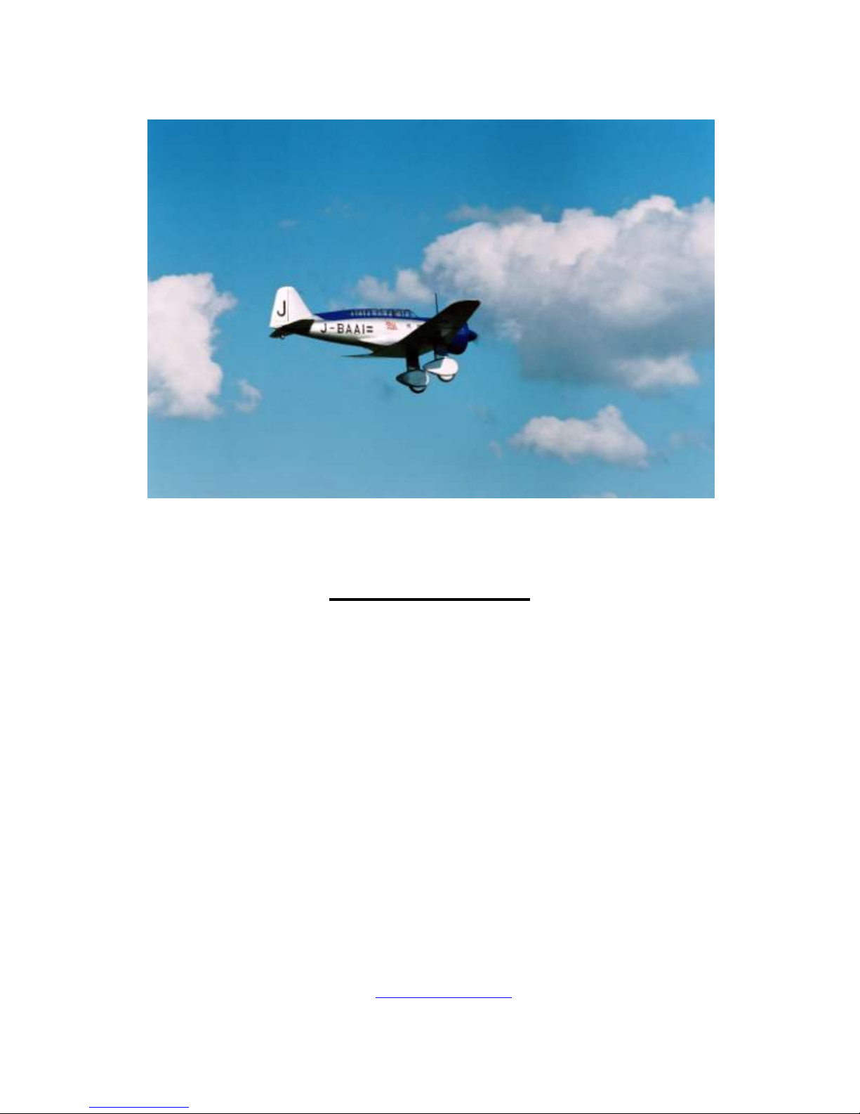
Mitsubishi Ki-15 “Babs”
In Quarter Scale
Construction Manual
Table of Contents:
Fuselage Assembly 2 Completion Views 60
Cowl Assembly 13 In-Flight Photos 68
Canopy Construction 17 Flying 70
Fiberglass Wheel Pants 21 Donald Thorpe Photos 72
Wooden Wheel Pants 26 Full-size Photos 74
Fin & Rudder Assembly 31 Markings 77
Stab & Elevator Assembly 35 References 80
Wing Assembly 40 Alternate Color Schemes 81
Surface Details 51 Four-view Drawing 84
Parts List 57 Paint Masks 85
Modelers’ Comments 59
The CD described on the plans is no longer available because all of its
information is shown here. Also, the email address that appears on the plans is no
longer valid. See the reference on www.mnbigbirds instead.
1
Fuselage Assembly
Overview of the fuselage assembly:
A horizontal crutch framework of ¼” sq. balsa is assembled over the plans on a flat
surface. First, the upper half of the fuselage is attached to this crutch. Then the cockpit interior is
painted and installed before sheeting. The glassed and primed vertical stabilizer is installed;
sheeting of the fuselage is completed and sanded. Then the fuselage is turned over; and the
lower halves of the fuselage formers, tank box and wing saddle are installed. Finally, the bottom
half is sheeted and wing filets are added.
Midway thru this process, before the lower nose and wing filet are completed, the wing is
mated to the fuselage. See notes in Wing Construction.
A removable horizontal stabilizer is shown. This provides access to the rudder and
elevator servos and it allows the airplane to be carried in a compact car. It also makes the
fuselage and stab easier to work on. If you prefer, the stab can just be glued in place.
The cowl assembly instructions are shown separately in another section.
Let’s begin.
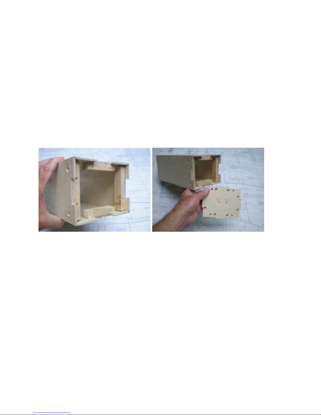
The fuel tank is enclosed in a plywood box. The front of the box is a removable firewall.
The firewall is screwed to hardwood blocks inside the tank box which are, in turn, screwed and glued to
the inside of the tank box. A total of eight flat-head aluminum screws are required for the firewall plus
another eight for the blocks. To adapt to engines other than those shown on the plans, the tank box can be
shifted forward or rearward as needed. Line the box with soft foam rubber for a snug fit of the tank. Slip
string or tape around the tank before installation. The string or tape can be used to pull the tank out later
as needed for maintenance. The rear and side seams of the tank box should be completely sealed with
glue so that if the tank leaks, fuel will spill out the front of the tank box and onto the ground, not into the
interior of the fuselage (you don’t want that to happen).
Fit the engine to the firewall with blind nuts at this time. Remove the engine.
Drill two holes in the firewall for the vent and fill lines. Install the tank and fuel lines and attach the
firewall to the tank box.
2
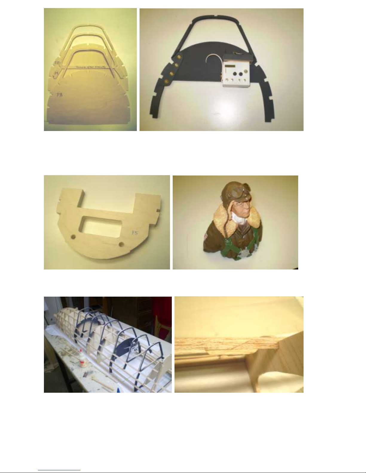
Cut out all the formers before beginning assembly. Note how some formers have temporary cross-braces
to hold their shape until installation. These can be cut away with a razor saw or Dremel wheel cutter after
installation and sheeting. Formers visible in the cockpit area should be assembled and painted before
installation. For example, F12 is shown above with the observer’s radio and other instruments.
Laminate F3, F4 and F5 together. Aces of Iron pilot looks worried as he
This causes F4 to be oddly recessed which contemplates the author’s flying skills.
is, nevertheless, scale.
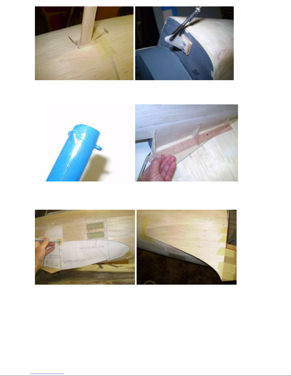
Assemble the upper half of the fuselage over the plans that are protected with waxed paper. The last
former position, F20, must hang over the edge of the work table--this space will be needed later when
attaching the tail cone. Adjust the crutch as needed to fit into the notches in the formers. Long stringers
should be spliced before installation. Note the reinforcing scab under the splice.
3
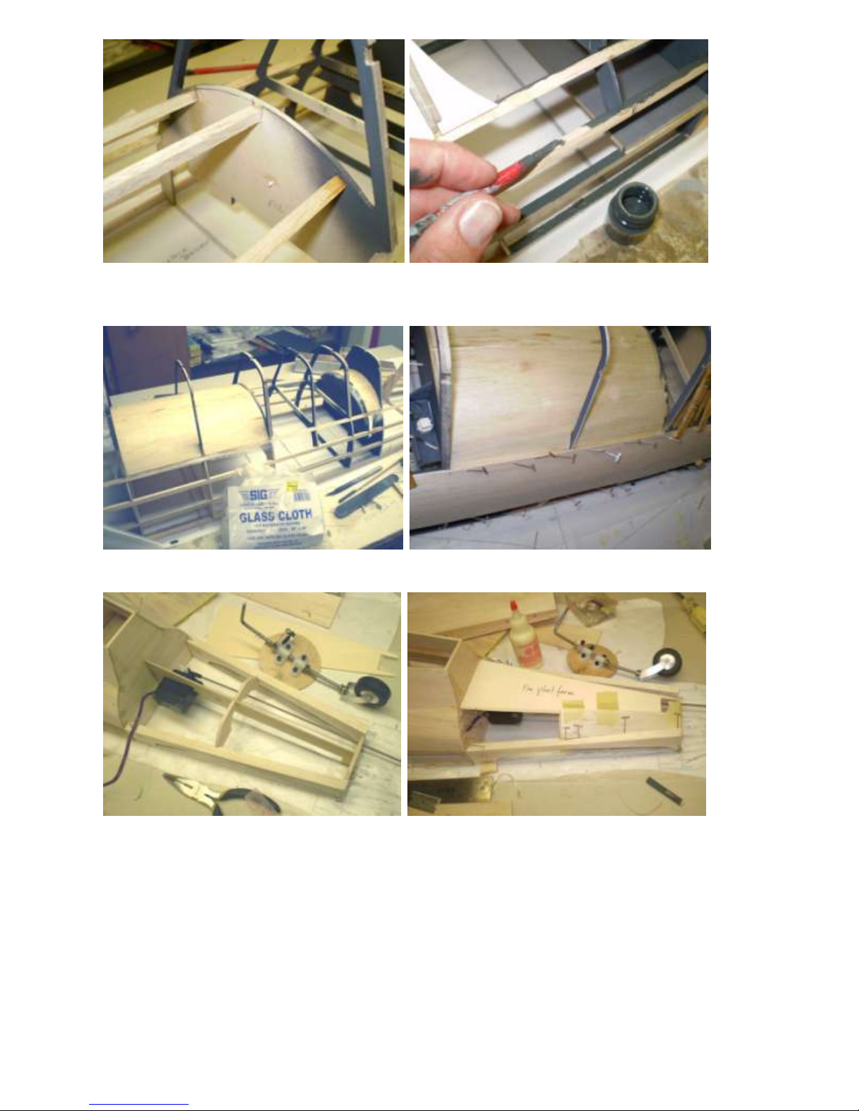
Stringers and sheeting butt up against F12. Paint the cockpit interior before sheeting.
Install rudder and elevator servo cables at this time, before sheeting.
Sheet and glass the cockpit interior surfaces. Then sheet the rest of the fuselage.
V3 is installed, rudder servo and p/r attached. Install fin platform and partial sheeting.
4
Fin platform ready to accept fin. Round the rear turtle deck with a razor plane.
Leave a temporary opening for access
to the rudder servo.
Fit the completed fin and rudder to the fin platform. After the fin and rudder are completed and primed,
install them on the fin platform. Reinforce the fin with gussets.
See also Fin And Rudder Assembly instructions.
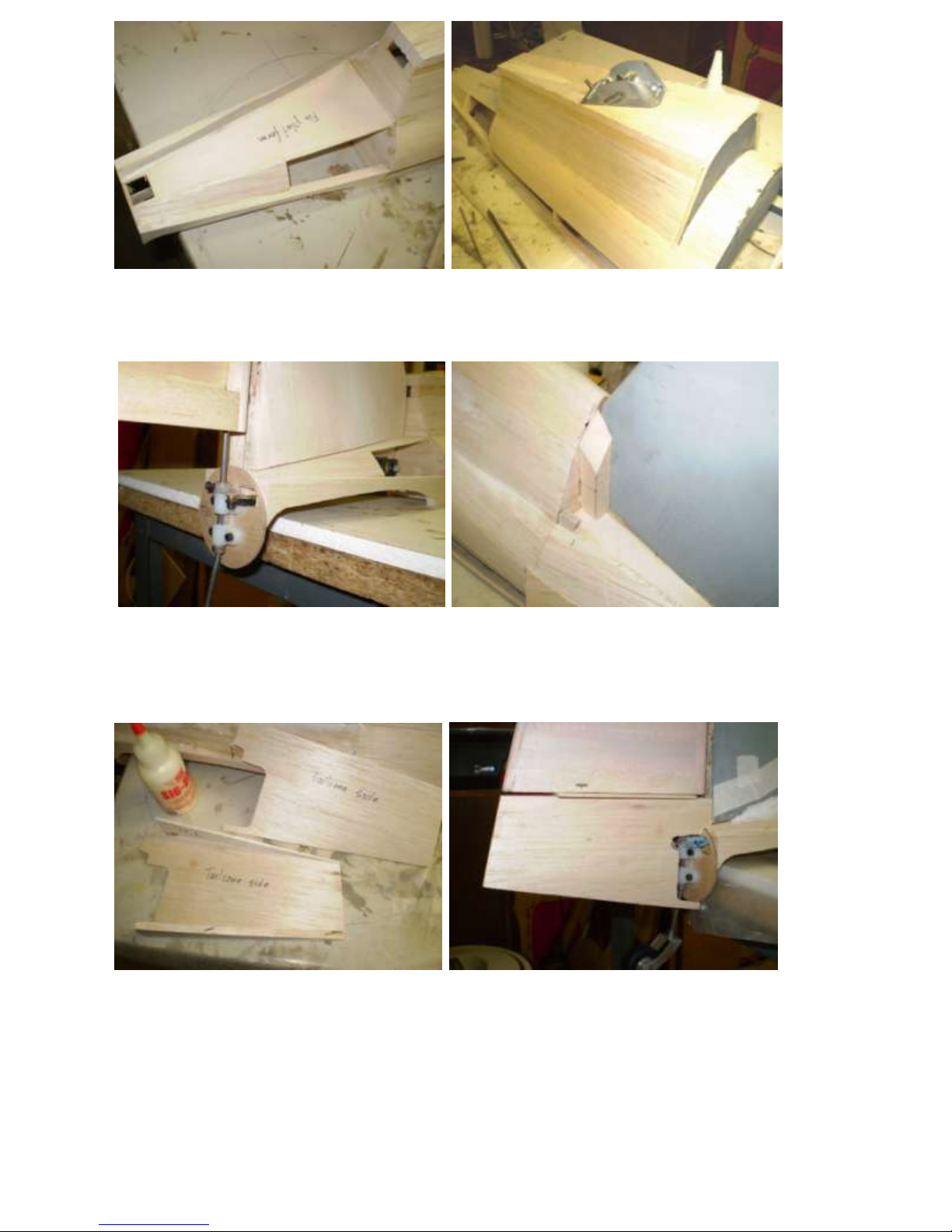
Assemble the tail cone. Install the tail cone.
Openings are clearances for the rudder horn and the tailwheel bracket.
5
Shape and hollow the tail cone fairings. Install the tail cone fairings on the tail cone.
Fit the stabilizer and install the elevator fairings at this time. See Stab and Elevator Assembly
instructions.
Turn the fuselage over, fin hanging over the edge of the workbench. Support the fuselage with foam
blocks. It is now ready to install the lower formers, rudder & elevator servo leads and the tank box.
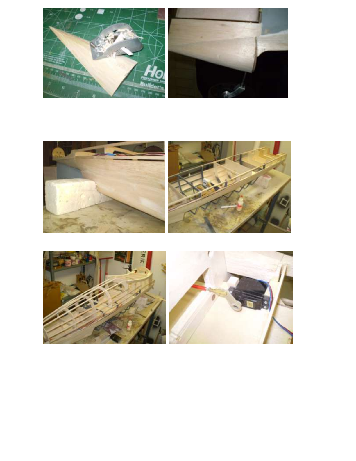
Install the lower formers and wing saddle. Install the tank box and throttle servo under it.
Trim pushrod to length later.
6
Reinforce the tank box at F1-F5 with Route sheet balsa for observer’s window.
triangular gussets. Depth equal to window thickness.
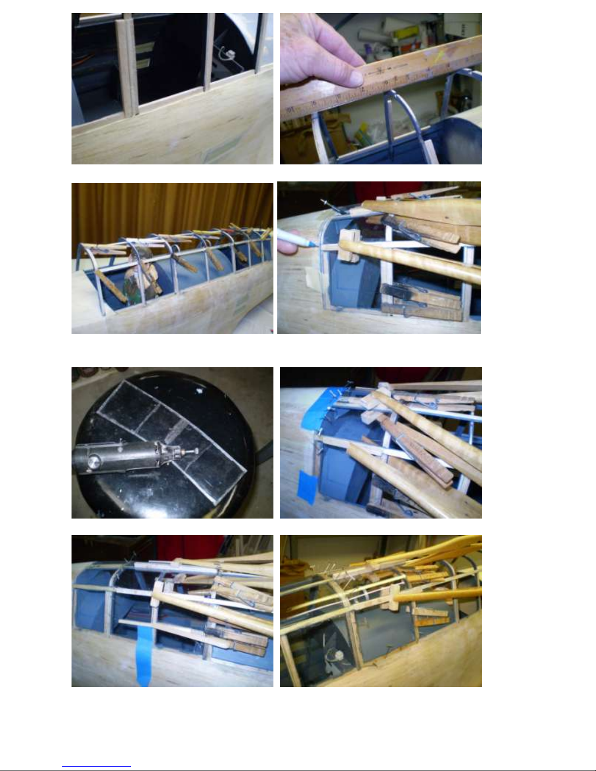
Install plastic windows, mask, paint inside, Paint and install the observer’s floors.
and attach over the observer’s area.
Wing saddle support before shaping. After shaping to match formers.
7
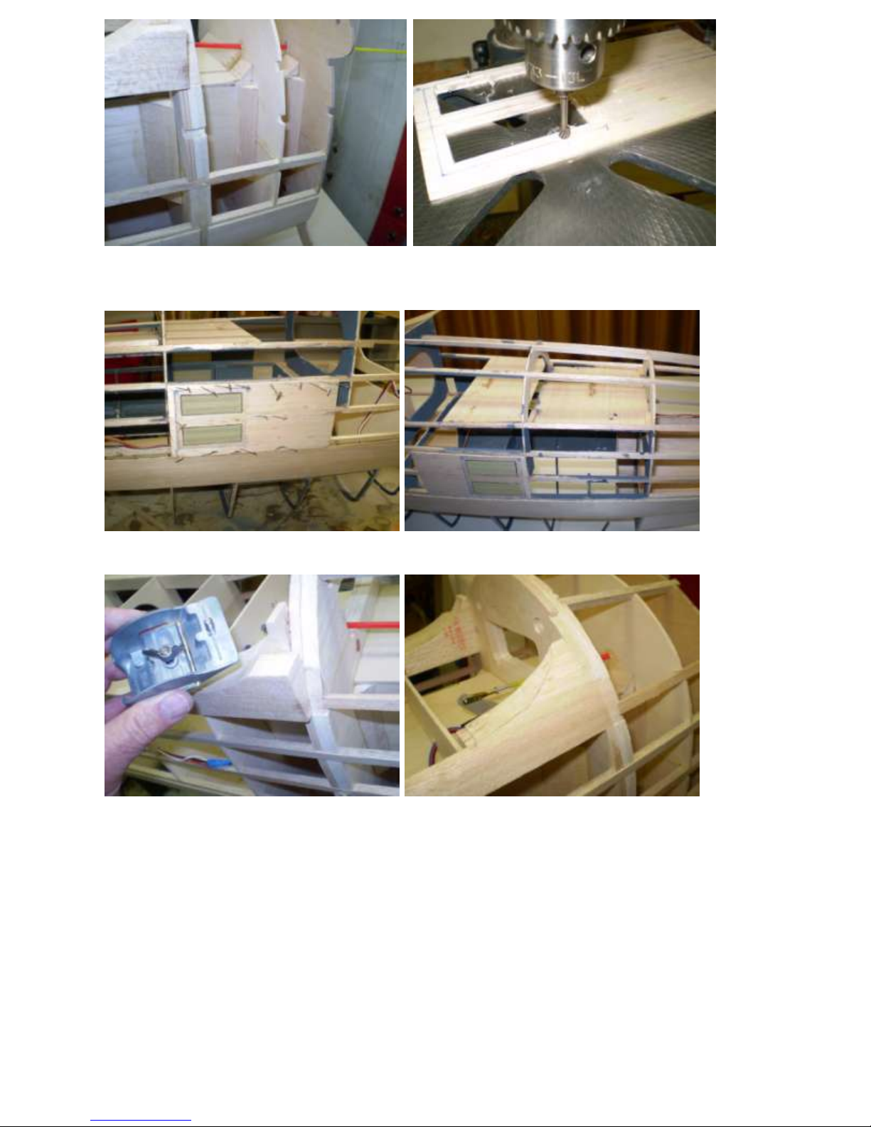
Install two wing bolt blocks. Drill holes for wing bolts under the flap.
The receiver switch can be hidden under the flap here too.
This step should be performed in conjunction with fitting the wing to the fuselage.
See Wing Assembly instructions.
Tap wing bolt blocks for two Assemble the antenna mast and its socket.
¼” x 20 nylon wing bolts. Tab is Popsicle stick or equivalent.
Harden the threads with thin CA. (The mast must be removable for transport.)
Moisten the outside surface and bend sheet balsa sections. Sheet the lower fuselage in large sections.
Fill seams, holes, low spots and other flaws with spackling paste. Sand smooth.
8
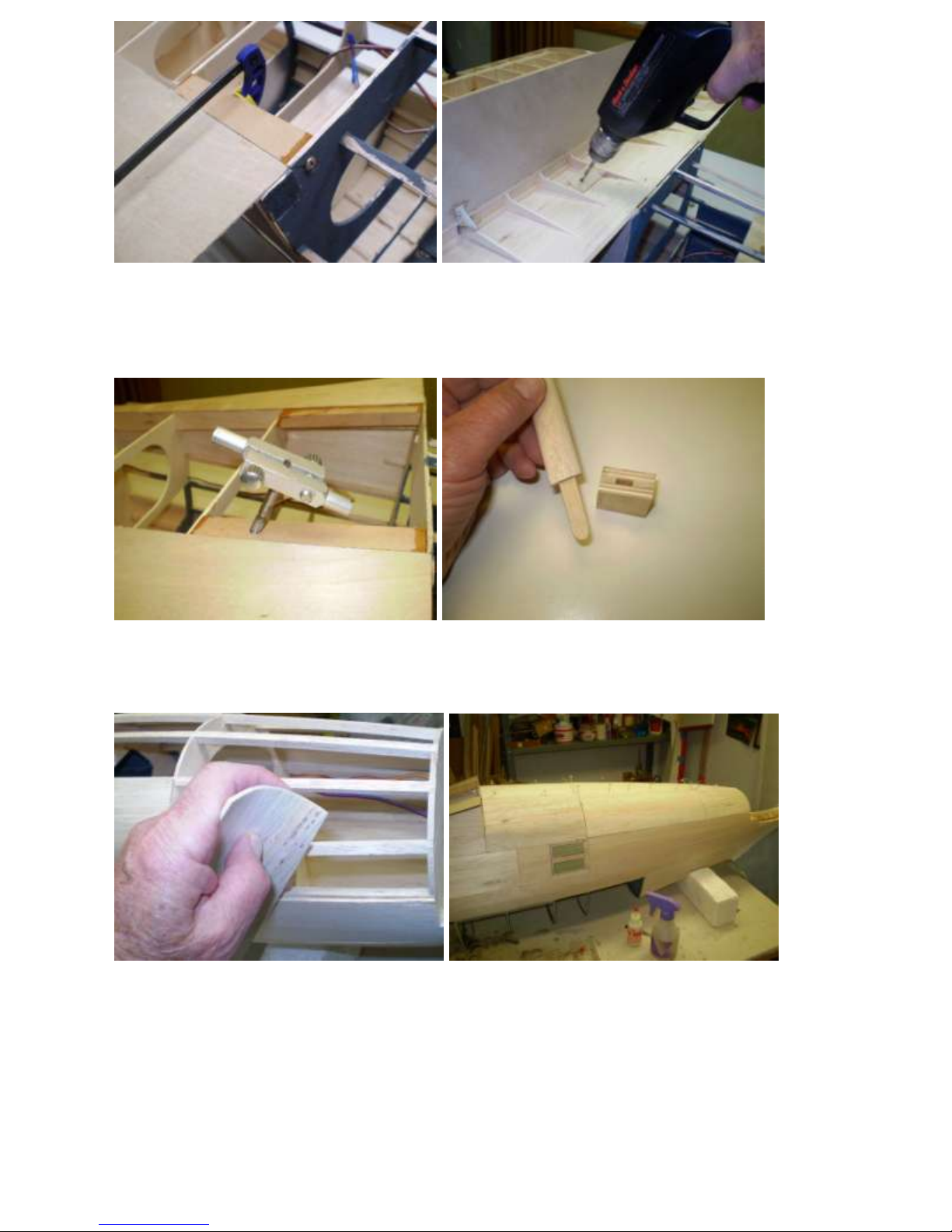
Epoxy the antenna mast socket in place. Rear scale antenna attachment is a nylon
control horn and clevis.
Drill a hole at the top of the antenna mast. Install filet formers with the wing in place.
Insert a cotter pin, bend the ends around Verify that formers align. Trim if necessary.
the mast and epoxy it in place.
Trace the filet pattern onto the fuselage Moisten the inside of the lower rear filet to using the
pattern on the plans. make it more flexible and glue it in place.
Secure with masking tape until the glue sets.
9
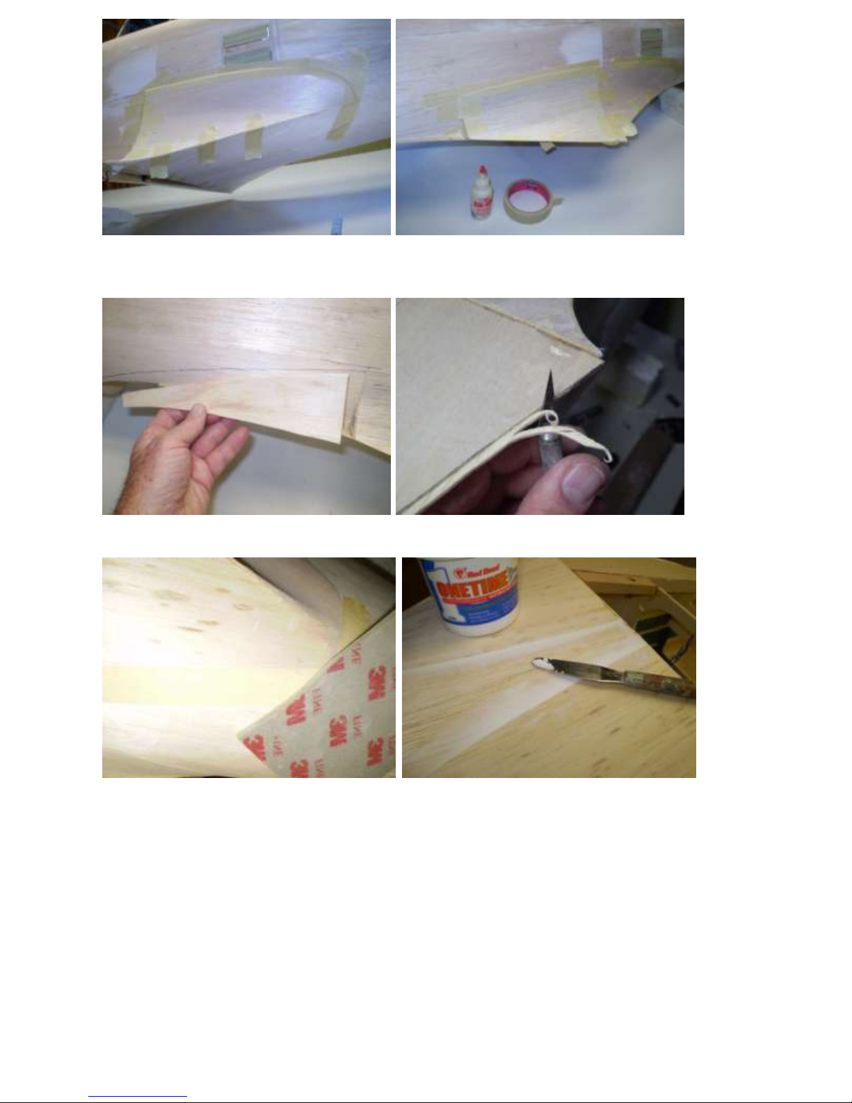
Glue the upper rear filet in place. Glue the upper middle filet in place.
Moisten the inside surface if necessary.
Glue the upper forward filet in place. Trim the wing filet to the wing saddle like so,
leaving a squared-off, not tapered, edge.
Sand the underside of the filet edges. Fill the edges with spackling putty and sand them smooth.
10
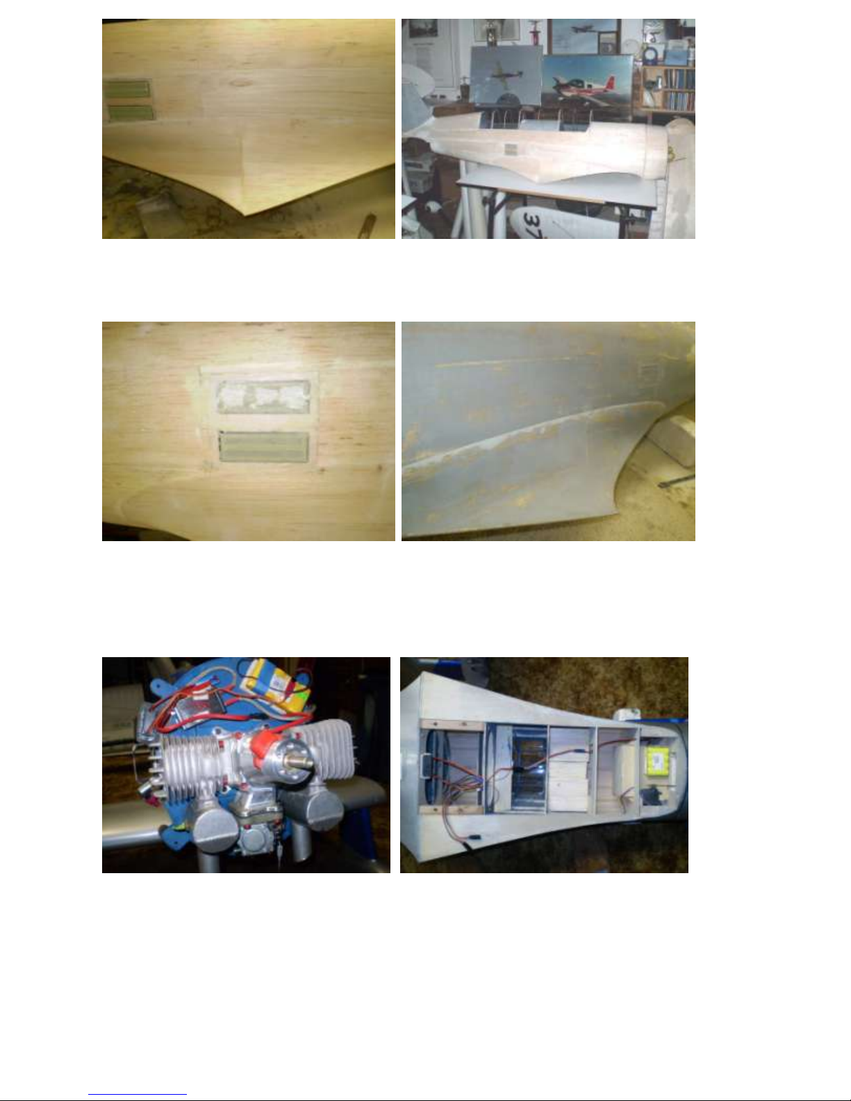
Fuselage sides and filets ready for glass. The entire fuselage is now ready for ¾ oz fiberglass cloth and
resin. Weight before glass as shown is less than 6 lbs.
Glass right over the masked observer’s windows.
After glassing, remove the masking tape After primer, apply masking tape to the filet
from the observer’s windows and apply edge and apply auto body filler. Sand to the
new tape is shown in the lower window. the tape and remove the tape. Result as shown
above simulates overlapping sheet metal.
Ignition module installation. Radio installation.
All wiring is spot-glued or taped in place to keep it from flopping around in flight.
11
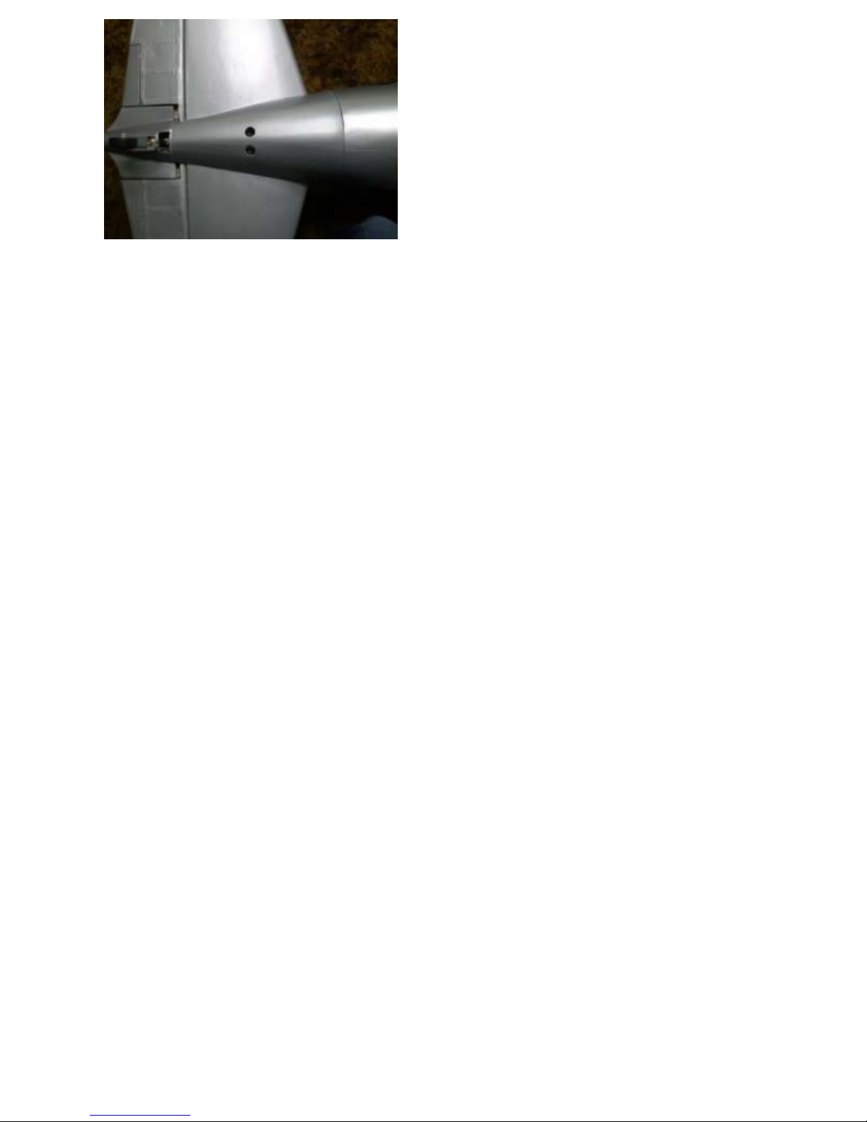
Stab attachment bolt access holes.
12
Cowl Construction
This section describes construction of a wooden cowl. Alternatively, a fiberglass cowl can be
purchased from Micko Aircraft and Accessories at www.mnbigbirds.com.
Some of the steps apply to the fiberglass cowl too. These are marked with an *.
*Fit C2 to F1. Blind nuts in C2 attach *Fit the cooling baffle C1 to the engine.
to the firewall, F1.
*For the glass cowl, C2 can be installed at this time, recessed into the cowl by 3/8 inch.
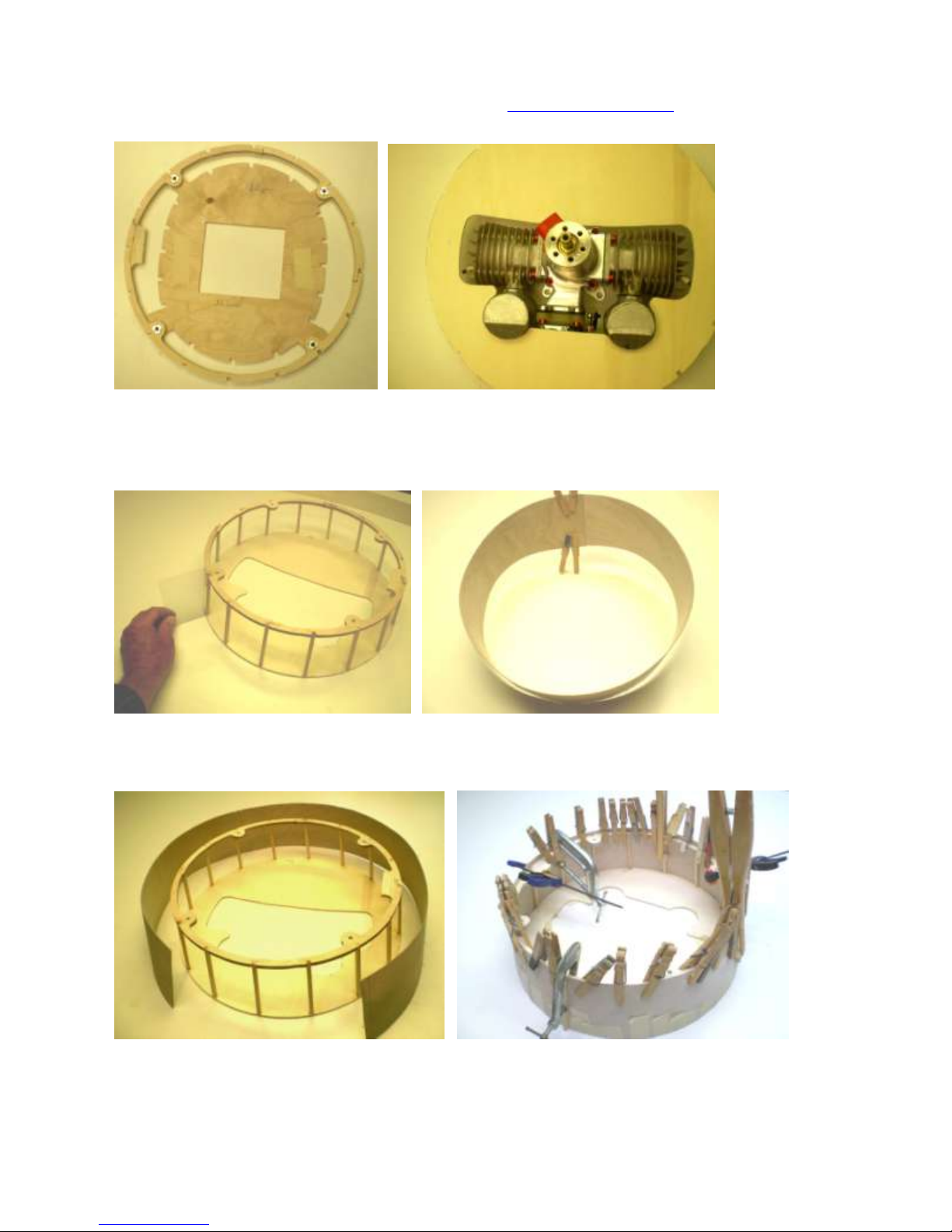
Use an angle template when assembling the cowl frame. Cut the cowl skin slightly oversized,
soak it in hot water and clamp the ends together until dry. This will bend the skin and make it
easier to glue to the frame.
Glue the pre-bent cowl skin to the frame with slow-cure epoxy. Clamp in place with lots of tape,
clothes pins, C-clamps, etc. Trim the front flush with C1. Trim the rear of the cowl skin to
extend 3/8” past C2.
13
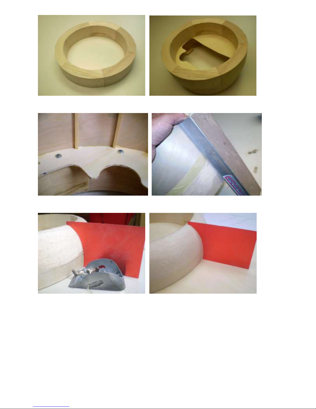
Nosebowl quadrants glued together. Nosebowl ready for shaping.
Temporarily attach the nosebowl to C1 with screws. Sand the outside flush with the cowl frame.
Use the template from the plans to rough-carve the nosebowl with a razor plane. Then sand the
outside to final shape, continuing to use the template as a guide. Very minor irregularities are
okay if they duplicate the hand-shaped sheet metal of the full-size.
14
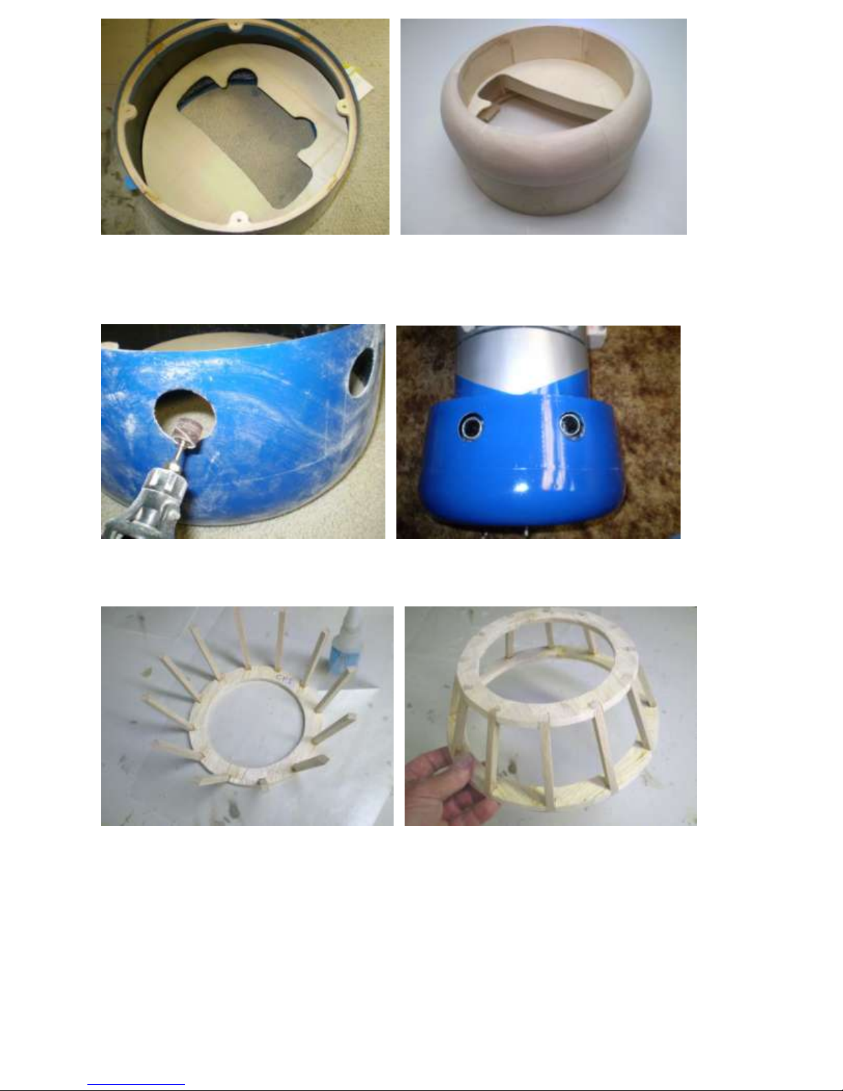
*Rear view of assembled cowl. Ready for glass and paint.
*For the glass cowl, C1 can be fitted but
not installed at this time.
*Cut the exhaust holes by drilling small holes approximately in the center of the exhaust pipes
while the engine and cowl are attached. Then enlarge them to slightly larger than the exhaust
pipes with a Dremel drum sander.
*Cut 12 engine fairing stringers to the shape shown on the plans, exactly the same length. Install
the stringers with thin CA using the angle template shown on the plans. Then add the rear
former CF2. Sheet the frame and cut openings to just barely clear the engine cylinders. Glass
and paint the result.
15
*Temporarily attach the spinner backplate to the engine fairing with double-faced foam tape and
bolt it to the engine. Fit and glue the fairing to C1. Then remove the backplate by cutting away
the foam tape. There must be at least 1/16-inch clearance between the fairing and the backplate.
Block-sand the front of the fairing if necessary.
*For the fiberglass cowl, it is easier to fit and install C1 at this time—pull it forward with tape
and glue it to the fairing and cowl sides.
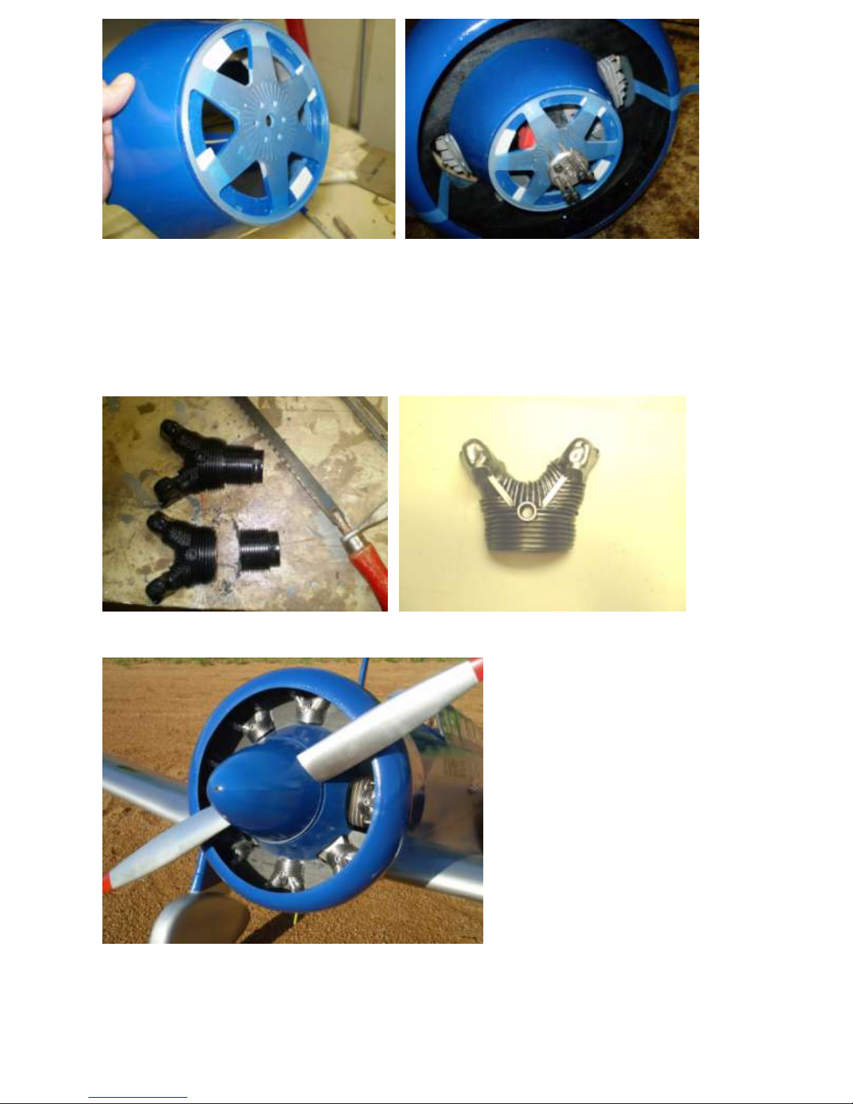
*Cut Williams Bros cylinders to size. *Lightly spray silver, leaving black shadows.
*Completed cowl with dummy engine cylinders in place,
minimally detailed. Lots of built-in headwind.
16

Canopy Construction
The canopy has 31 windows! (Plus 5 windows elsewhere.) All but one are flat sheet. Assembly
proceeds from rear to front, installing the windscreen last.
The only window that must be molded is the upper part of the windscreen. A fully
formed complete windscreen can also be purchased from Micko Aircraft and Accessories at
www.mnbigbirds.com.
The upper windscreen can be molded without vacuum forming by pulling hot plastic over a
carved balsa form. The lower part of the windscreen is folded flat sheet supported by a frame
(the patterns are on the plans). A better solution is to purchase a fully formed complete
windscreen from Micko Aircraft and Accessories.
Access to the cockpit will be difficult after the canopy is installed. So, before assembling
the canopy, the interior of the cockpit should be completed.
Increase the gluing area of each frame Verify frame recess with scrap plastic so that
with additional balsa sticks. the canopy will be flush with the fuselage.
17
Frame wideners in place. Verify that the frames line up. Block-sand if they don’t.
Paint and install horizontal canopy rails. Mark each piece prior to trimming.
Roughen the canopy edge for gluing. Epoxy the rearmost canopy section in place.
Epoxy the observer’s section in place. Install the section in front of the observer.
18

Epoxy the next canopy section in place. Clean up spilled epoxy with alcohol before it sets.
Glue the Micko windscreen in place. Mark the outline of the windscreen
Hold it in place with tape until the frames using a paper pattern cut from the
epoxy sets. plans.
Mark the canopy frames with 3/8” tape. Punch ½” dia circles from masking tape.
Masking tape will be applied inside these Apply to all corners so that all windows
squares, then the 3/8” tape is removed will be rounded.
.
19
Mask the edge of each window using the Cover each window with masking tape.
3/8” tape as a guide. Then, remove the 3/8” tape.
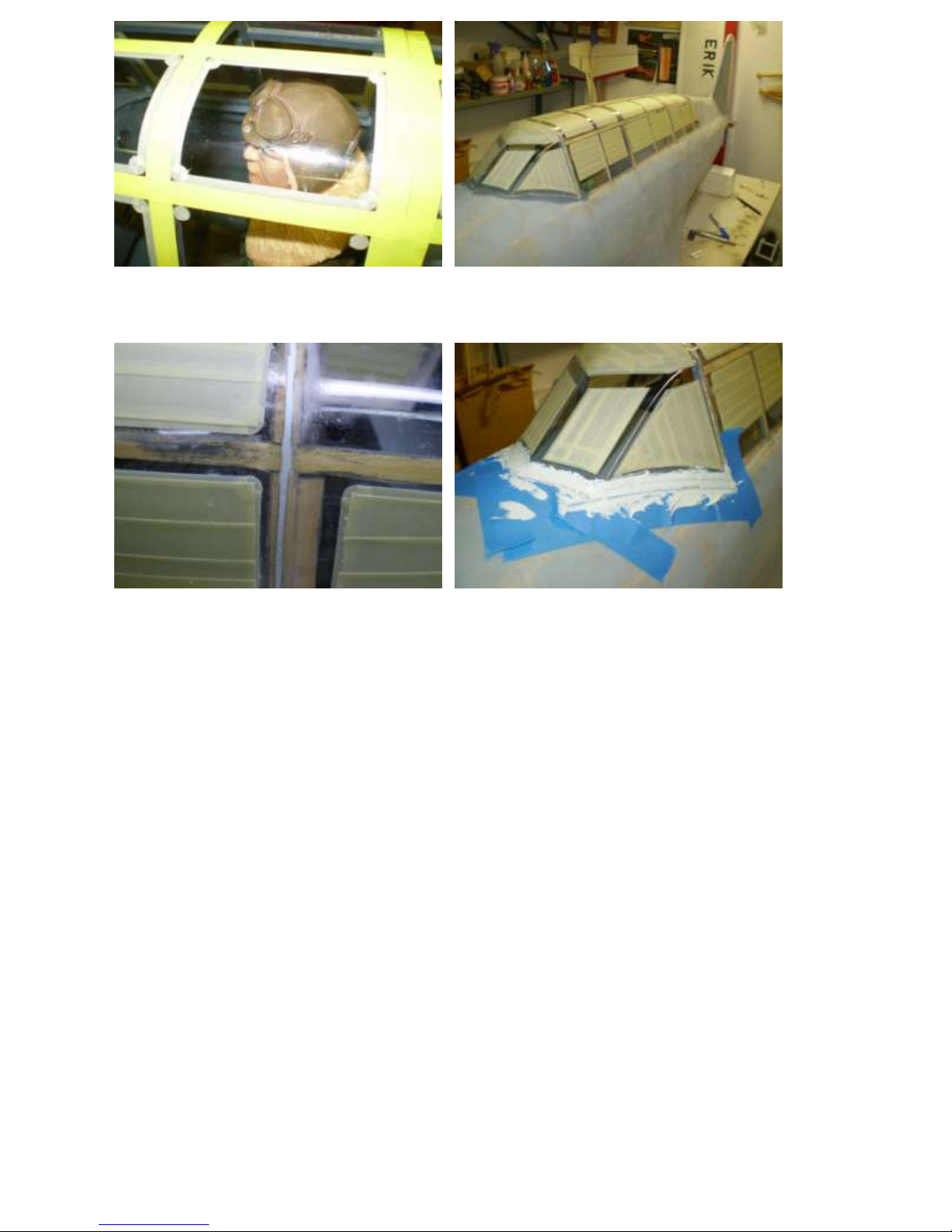
Fill the seams and pin holes between Form the lower windscreen filet with auto
sections with auto body putty. body putty. Sand smooth. Remove tape.
The canopy area is now ready for primer.
20
Fiberglass Wheel Pant Assembly
The plans and instruction manual show wooden wheel pants too. But fiberglass pants are 2-3
times lighter than wood, more durable, typically cheaper, and a lot less work. So I recommend
fiberglass pants. You can make your own fiberglass pants by first assembling one wooden pant
and using it, as a plug, to make two molds. Else, high-quality fiberglass pant sets are available
from Micko Aircraft and Accessories at www.mnbigbirds.com.
The pant is secured to the strut by blocks of wood resting against the oleo portion of the
strut and the axle in a hole in layer E. The entire assembly moves up and down with the oleo.
When compressed, the pant moves into the bottom of the wing.
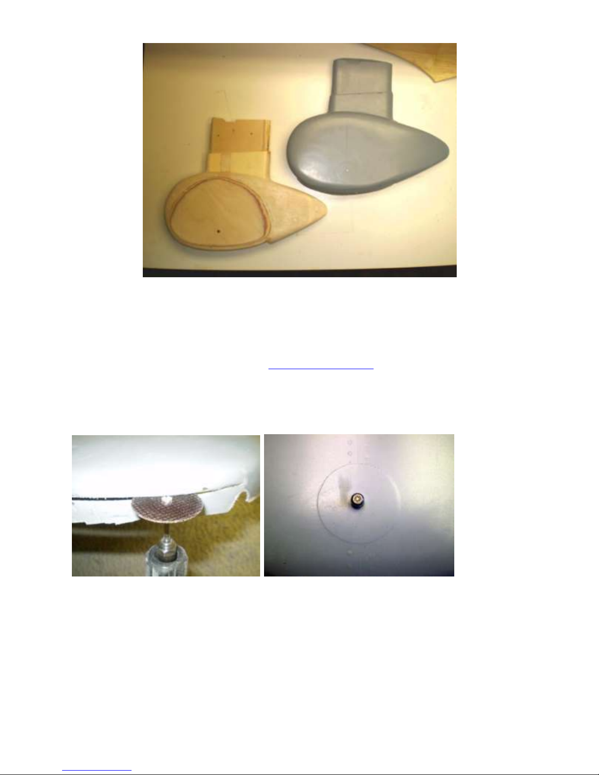
Cut openings for the wheel and strut. Drill ¼” holes in the pant sides for
Save the scrap. the axle.
21
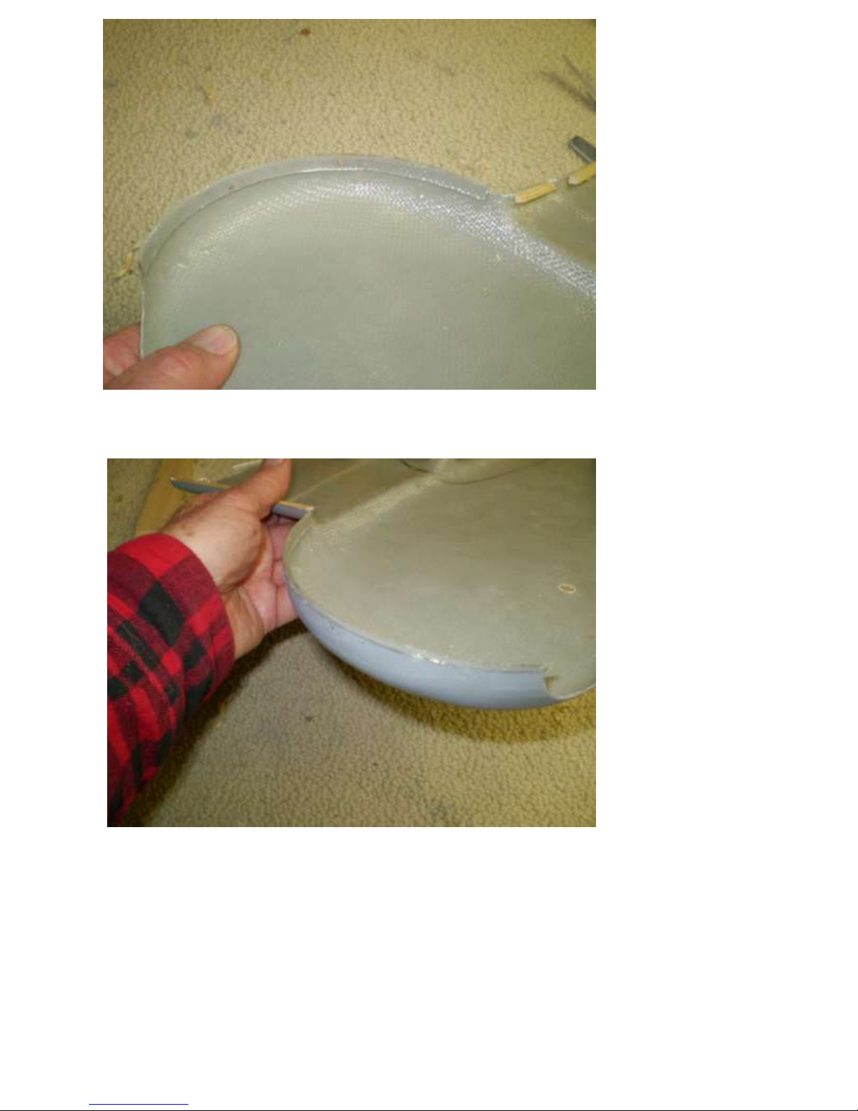
Trim the scrap and install a fiberglass lip inside one side of the pant at the curved edges. This
will strengthen and align the halves when they are glued together.
22
The notch in the top of the pant is necessary clearance for the mounting bracket when the
oleo is compressed.
While the axle is in the hole in the lower pant, epoxy hard ½” sheet balsa blocks beside
the upper strut. Refer to the plans for positioning. Smaller hard balsa sticks at the
straight edges are trimmed flush at the edge of the pant. Do this on both pant halves.
When the pant halves are epoxied together, these sticks will secure the edges of the pants
together.
23
Pant half ready to be glued to its other half, axle in hole in pant.
The strut is in contact with the inside of the pant but it is not attached to it yet. The
unpainted aluminum sheet wheel cover is glued to wheel with methacrylate glue.
Pant halves being epoxied together. Fill and smooth seams with auto
Axle protrudes thru holes in pant, body filler. Evercoat Euro-Soft
both sides. Polyester Glazing Putty shown here.
For extra security, insert a sheet metal screw or self-tapping machine screw thru the pant and into
the strut three inches above the axle, inside surface only. This will reduce wear on the axle holes.
24
File two flat spots on the landing gear strut and install it in the wing. Use medium thread-locker
on the set-screw threads. Set-screw access is thru a hole in the leading edge and another hole in
the rib. Note how the upper pant moves into the wing with oleo compression.
25
Wooden Wheel Pants Assembly Sequence
The wooden wheel pants are composed of several layers. Each pant is composed of a left half
and right half held together by four recessed bolts. This allows disassembly for maintenance and
repair, with the option of permanent gluing together if you do not want a visible seam. Blind
nuts and washers are imbedded in the innermost layers, layer A, with access to the bolts via a
small ball driver. The pant is secured to the strut by blocks of wood resting against the oleo
portion of the strut, the axle in holes in the E layers and one screw in the lower strut.
The entire assembly moves up and down with the oleo. When compressed, the pant
moves into the bottom of the wing.
Note that wooden pants weigh 2-3 times more than fiberglass pants. They are a lot more
work and cost more too. Fiberglass pants are available from Micko Aircraft and Accessories at
www.mnbigbirds.com.
Install blind nuts and washers in level A. Bolt the A layers together.
Press B, C and D to A so that the bolt head in A leaves an indentation in B. Then drill bolt access
holes in B, C and D to align with A.
26
 Loading...