

Mitsubishi Electric HG-KN, HG-SN Instruction Manual

General-Purpose AC Servo
MODEL
HG-KN
HG-SN
SERVO MOTOR INSTRUCTION MANUAL
D
Safety Instructions
Please read the instructions carefully before using the equipment.
To use the equipment correctly, do not attempt to install, operate, maintain or inspect the equipment until you
have read through this Instruction Manual and appended documents carefully. Do not use the equipment
until you have a full knowledge of the equipment, safety information and instructions.
In this Instruction Manual, the safety instruction levels are classified into "WARNING" and "CAUTION".
WARNING
CAUTION
Note that the
Please follow the instructions of both levels because they are important to personnel safety.
What must not be done and what must be done are indicated by the following diagrammatic symbols.
CAUTION level may lead to a serious consequence according to conditions.
Indicates that incorrect handling may cause hazardous conditions,
resulting in death or severe injury.
Indicates that incorrect handling may cause hazardous conditions,
resulting in medium or slight injury to personnel or may cause physical
damage.
Indicates what must not be done. For example, "No Fire" is indicated by
Indicates what must be done. For example, grounding is indicated by .
In this Instruction Manual, instructions at a lower level than the above, instructions for other functions, and so
on are classified into "POINT".
After reading this Instruction Manual, keep it accessible to the operator.
.
A - 1
1. To prevent electric shock, note the following
WARNING
Before wiring and inspections, turn off the power and wait for 15 minutes or more until the charge lamp
turns off. Otherwise, an electric shock may occur. In addition, when confirming whether the charge lamp
is off or not, always confirm it from the front of the servo amplifier.
Ground the servo amplifier and servo motor securely.
Any person who is involved in wiring and inspection should be fully competent to do the work.
Do not attempt to wire the servo amplifier and servo motor until they have been installed. Otherwise, it
may cause an electric shock.
The cables should not be damaged, stressed, loaded, or pinched. Otherwise, it may cause an electric
shock.
To avoid an electric shock, insulate the connections of the power supply terminals.
2. To prevent fire, note the following
CAUTION
Install the servo motor on incombustible material. Installing them directly or close to combustibles will
lead to smoke or a fire.
Provide an adequate protection to prevent screws and other conductive matter, oil and other combustible
matter from entering the servo motor.
3. To prevent injury, note the following
CAUTION
Only the power/signal specified in the Instruction Manual must be supplied/applied to each terminal.
Otherwise, an electric shock, fire, injury, etc. may occur.
Connect cables to the correct terminals. Otherwise, a burst, damage, etc. may occur.
Ensure that polarity (+/-) is correct. Otherwise, a burst, damage, etc. may occur.
The servo motor, etc. may be hot while power is on and for some time after power-off. Take safety
measures such as providing covers to avoid accidentally touching them by hands and parts such as
cables.
The surface temperature of the servo motor may exceed 100 ˚C depending on its mounting and
operating conditions.
During operation, never touch the rotor of the servo motor. Otherwise, it may cause injury.
A - 2
4. Additional instructions
The following instructions should also be fully noted. Incorrect handling may cause a malfunction, injury,
electric shock, fire, etc.
(1) Transportation and installation
CAUTION
Transport the products correctly according to their mass.
Stacking in excess of the specified number of product packages is not allowed.
Do not hold the cables, connectors, shaft, or encoder when carrying the servo motor. Otherwise, it may
drop.
Install the servo motor in a load-bearing place in accordance with the Instruction Manual.
Do not get on or put heavy load on the equipment. Otherwise, it may cause injury.
The equipment must be installed in the specified direction.
Do not install or operate the servo motor which have been damaged or have any parts missing.
Do not drop or strike the servo motor. Otherwise, injury, malfunction, etc. may occur.
Securely fix the servo motor to the machine. If being attached insecurely, the motor may come off during
operation.
When handling the servo motor, be careful with the sharp edges of the servo motor, shaft keyway, or
others.
Do not strike the connector. Otherwise, a connection failure, malfunction, etc. may occur.
Be sure to measure the vibration level with the servo motor mounted on the machine when checking the
vibration level. A great vibration may cause the early damage of a bearing, encoder, and brake. The
great vibration may also cause the poor connector connection or bolt looseness.
For the gain adjustment at the equipment startup, check the torque waveform and the speed waveform
with a measurement device to check that no vibration occurs. If the vibration occurs due to high gain, the
vibration may cause the early damage of the servo motor.
Take safety measures, e.g. provide covers, to prevent accidental access to the rotor of the servo motor
during operation.
Never hit the servo motor or shaft, especially when coupling the servo motor to the machine. Otherwise,
the encoder may malfunction.
Do not subject the servo motor shaft to more than the permissible load. Otherwise, the shaft may break.
To prevent a fire or injury from occurring in case of an earthquake or other natural disasters, securely
install, mount, and wire the servo motor in accordance with the Instruction Manual.
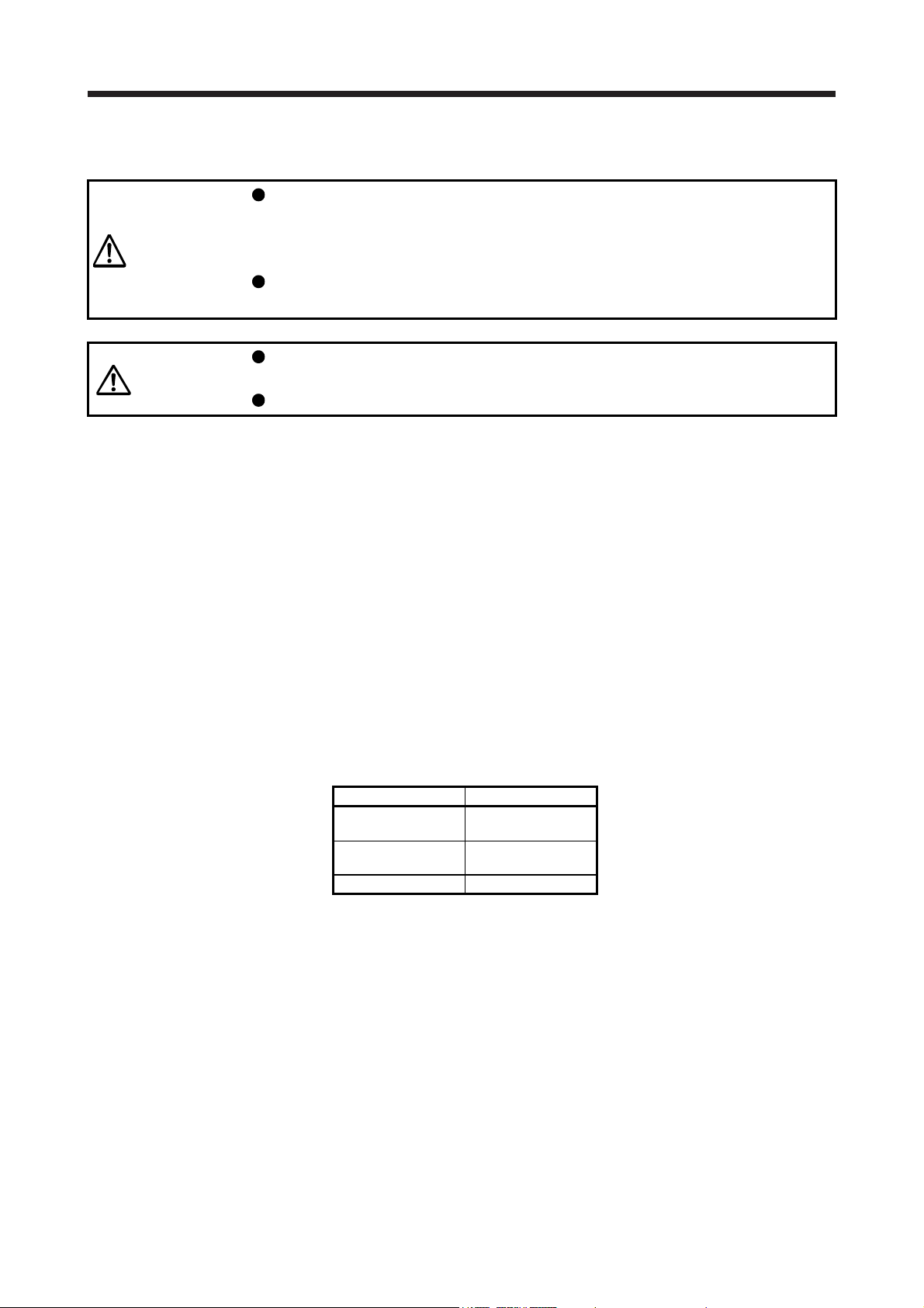
When you keep or use the equipment, please fulfill the following environment.
Item Environment
Ambient temperature
Storage -15 °C to 70 °C (non-freezing)
Ambient humidity
Storage 10 %RH to 90 %RH (non-condensing)
Altitude Max. 2000 m above sea level (Note)
HG-SN52/HG-SN102/HG-SN152 X, Y: 24.5 m/s2
Vibration resistance
HG-SN202/HG-SN302 X: 24.5 m/s2 Y: 49 m/s2
Note. Contact your local sales office for the altitude for options.
Ambience
Operation 0 °C to 40 °C (non-freezing)
Operation 10 %RH to 80 %RH (non-condensing)
Indoors (no direct sunlight), free from corrosive
gas, flammable gas, oil mist, dust, and dirt
HG-KN series X, Y: 49 m/s2
A - 3

(2) Wiring
CAUTION
Wire the equipment correctly and securely. Otherwise, the servo motor may operate unexpectedly.
Make sure to connect the cables and connectors by using the fixing screws and the locking mechanism.
Otherwise, the cables and connectors may be disconnected during operation.
Do not install a power capacitor, surge killer, or radio noise filter (optional FR-BIF) on the servo amplifier
output side.
To avoid a malfunction, connect the wires to the correct phase terminals (U/V/W) of the servo amplifier
and servo motor.
Connect the servo amplifier power output (U/V/W) to the servo motor power input (U/V/W) directly. Do
not let a magnetic contactor, etc. intervene. Otherwise, it may cause a malfunction.
Servo amplifier
U
V
W
Servo motor
U
V
W
Servo motorServo amplifier
U
M
V
W
U
V
W
M
Do not connect AC power supply directly to the servo motor. Otherwise, it may cause a malfunction.
When the cable is not tightened enough to the terminal block, the cable or terminal block may generate
heat because of the poor contact. Be sure to tighten the cable with specified torque.
(3) Test run and adjustment
CAUTION
Before operation, check the parameter settings. Improper settings may cause some machines to operate
unexpectedly.
Never make a drastic adjustment or change to the parameter values as doing so will make the operation
unstable.
A - 4
(4) Usage
CAUTION
When it is assumed that a hazardous condition may occur due to a power failure or product malfunction,
use a servo motor with an external brake to prevent the condition.
For equipment in which the moving part of the machine may collide against the load side, install a limit
switch or stopper to the end of the moving part. The machine may be damaged due to a collision.
Do not scratch the coated surface with hard objects nor clean the coated surface with an organic solvent.
Doing so may scuff the surface.
Do not disassemble, repair, or modify the product. Otherwise, an electric shock, fire, injury, etc. may
occur. Disassembled, repaired, and/or modified products are not covered under warranty.
Use the servo amplifier with the specified servo motor.
Correctly wire options and peripheral equipment, etc. in the correct combination. Otherwise, an electric
shock, fire, injury, etc. may occur.
The electromagnetic brake on the servo motor is designed to hold the motor shaft and should not be
used for ordinary braking.
For such reasons as incorrect wiring, service life, and mechanical structure (e.g. where a ball screw and
the servo motor are coupled via a timing belt), the electromagnetic brake may not hold the motor shaft.
To ensure safety, install a stopper on the machine side.
If the dynamic brake is activated at power-off, alarm occurrence, etc., do not rotate the servo motor by an
external force. Otherwise, it may cause a fire.
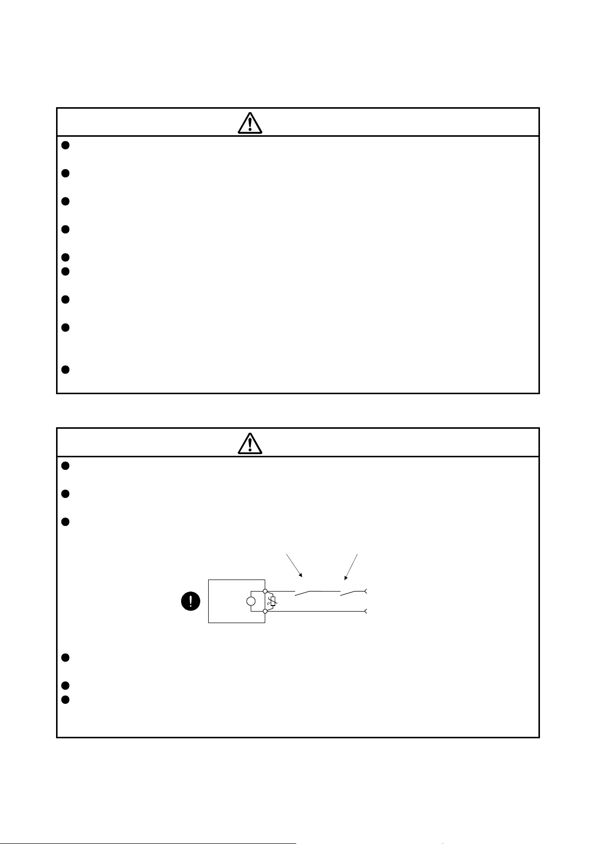
(5) Corrective actions
CAUTION
Ensure safety by confirming the power off, etc. before performing corrective actions. Otherwise, it may
cause an accident.
When it is assumed that a hazardous condition may occur due to a power failure or product malfunction,
use a servo motor with an electromagnetic brake or external brake to prevent the condition.
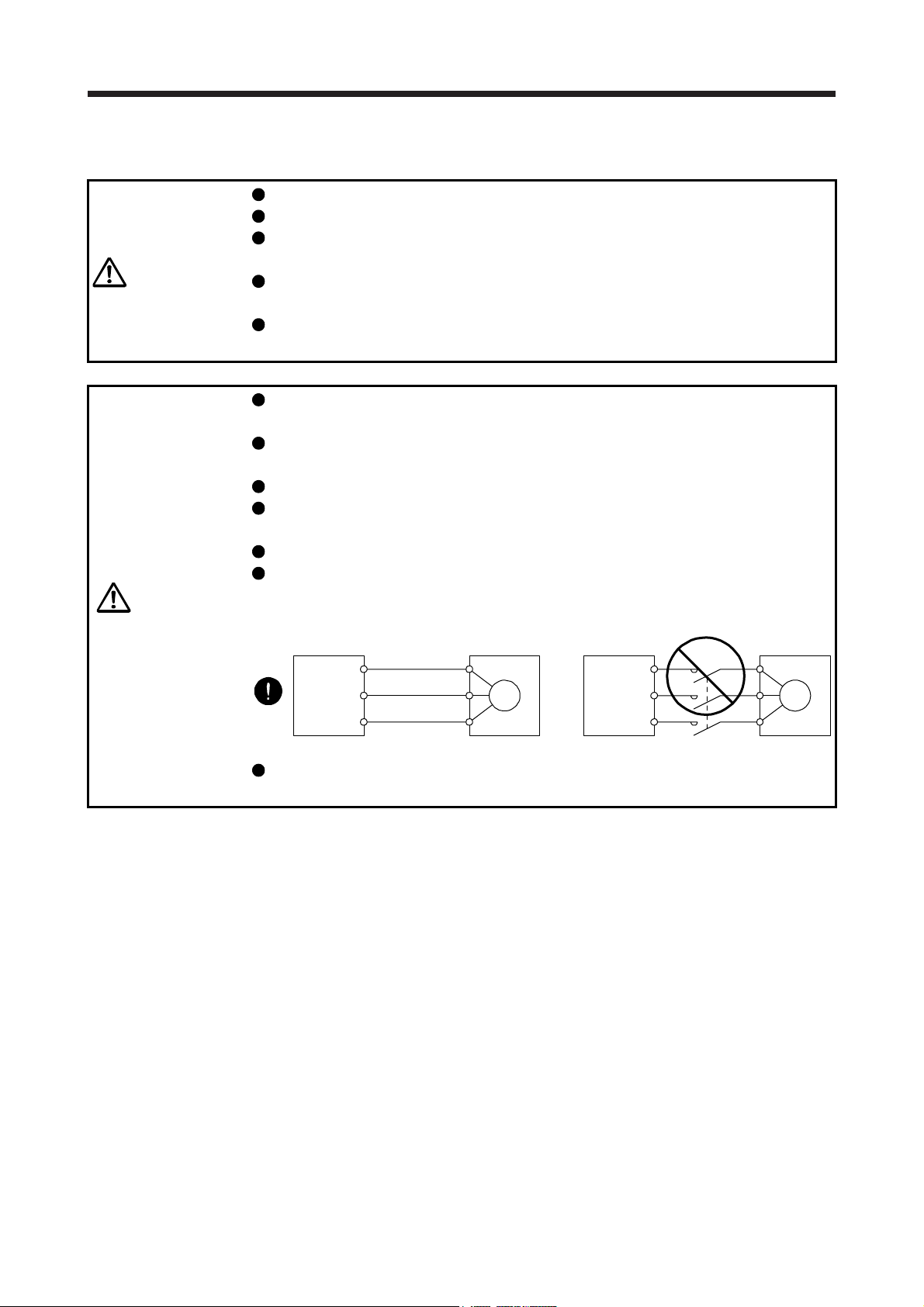
Configure an electromagnetic brake circuit which is interlocked with an external emergency stop switch.
Contacts must be opened when ALM
(Malfunction) or MBR (Electromagnetic
brake interlock) turns off.
Servo motor
B
Electromagnetic brake
When any alarm has occurred, eliminate its cause, ensure safety, and deactivate the alarm before
restarting operation.
Provide an adequate protection to prevent unexpected restart after an instantaneous power failure.
To prevent an electric shock, injury, or fire from occurring after an earthquake or other natural disasters,
ensure safety by checking conditions, such as the installation, mounting, wiring, and equipment before
switching the power on.
Contacts must be opened
with the emergency stop switch.
RA
24 V DC
A - 5
(6) Storage
CAUTION
Note the followings when storing the servo motor for an extended period of time (guideline: three or more
months).
Always store the servo motor indoors in a clean and dry place.
If it is stored in a dusty or damp place, make adequate provision, e.g. cover the whole product.
If the insulation resistance of the winding decreases, check how to store the equipment.
Though the motor is rust-proofed before shipment using paint or rust prevention oil, rust may be
produced depending on the storage conditions or storage period. If the servo motor is to be stored for
longer than six months, apply rust prevention oil again especially to the machined surfaces of the shaft,
etc.
Before using the product after storage for an extended period of time, hand-turn the servo motor output
shaft to confirm that nothing is wrong with the servo motor. When the servo motor is equipped with an
electromagnetic brake, check it after releasing the electromagnetic brake with the brake power supply.
When the product has been stored for an extended period of time, contact your local sales office.
(7) General instruction
To illustrate details, the equipment in the diagrams of this Instruction Manual may have been drawn
without covers and safety guards. When the equipment is operated, the covers and safety guards must
be installed as specified. Operation must be performed in accordance with this Instruction Manual.
DISPOSAL OF WASTE
Please dispose a servo motor and other options according to your local laws and regulations.
«Cables used for wiring»
Wires mentioned in this Instruction Manual are selected based on the ambient temperature of 40 ˚C.
«U.S. customary units»
U.S. customary units are not shown in this manual. Convert the values if necessary according to the
following table.
Mass 1 [kg] 2.2046 [lb]
Length 1 [mm] 0.03937 [inch]
Torque 1 [N•m] 141.6 [oz•inch]
Moment of inertia 1 [(× 10-4 kg•m2)] 5.4675 [oz•inch2]
Load (thrust load/axial load) 1 [N] 0.2248 [lbf]
Temperature N [°C] × 9/5 + 32 N [°F]
Quantity SI (metric) unit U.S. customary unit
A - 6
CONTENTS
1. INTRODUCTION 1- 1 to 1- 6
1.1 Rating plate ....................................................................................................................................... 1- 1
1.2 Parts identification ............................................................................................................................. 1- 2
1.3 Electromagnetic brake ...................................................................................................................... 1- 3
1.4 Servo motor shaft shapes ................................................................................................................. 1- 5
2. INSTALLATION 2- 1 to 2- 8
2.1 Mounting direction............................................................................................................................. 2- 2
2.2 Load mounting/dismounting precautions .......................................................................................... 2- 3
2.3 Permissible load for the shaft ........................................................................................................... 2- 4
2.4 Protection from oil and water ............................................................................................................ 2- 4
2.5 Cable ................................................................................................................................................. 2- 5
2.6 Servo motor with oil seal ................................................................................................................... 2- 5
2.7 Inspection items ................................................................................................................................ 2- 6
2.8 Parts having service life .................................................................................................................... 2- 6
2.9 Machine accuracies .......................................................................................................................... 2- 7
2.10 Mounting servo motors ................................................................................................................. 11- 7
2.11 Restrictions when using the equipment at altitudes exceeding 1000 m and up to 2000 m
above sea level ............................................................................................................................. 11- 7
3. CONNECTORS USED FOR SERVO MOTOR WIRING 3- 1 to 3- 6
3.1 Selection of connectors .................................................................................................................... 3- 1
3.2 Wiring connectors (connector configurations A/B/C) ........................................................................ 3- 2
3.3 Wiring connectors (connector configurations D/E/F/G) .................................................................... 3- 3
4. CONNECTION OF SERVO AMPLIFIER AND SERVO MOTOR 4- 1 to 4- 8
4.1 Connection instructions .................................................................................................................... 4- 2
4.2 Wiring ................................................................................................................................................ 4- 3
4.2.1 HG-KN series servo motor ......................................................................................................... 4- 3
4.2.2 HG-SN series servo motor ......................................................................................................... 4- 5
4.3 Selection example of wires ............................................................................................................... 4- 7
5. WIRING OPTION 5- 1 to 5-22
5.1 Cable/connector sets ........................................................................................................................ 5- 1
5.1.1 Combinations of cable/connector sets ....................................................................................... 5- 2
5.1.2 Cable and connector list ............................................................................................................. 5- 3
5.2 Encoder cable/connector sets .......................................................................................................... 5- 6
5.3 Servo motor power cable ................................................................................................................. 5-17
5.4 Electromagnetic brake cable ........................................................................................................... 5-19
5.5 Wires for option cables .................................................................................................................... 5-20
6. HG-KN SERIES 6- 1 to 6-18
6.1 Model designation ............................................................................................................................. 6- 1
6.2 Combination list of servo motors and servo amplifiers ..................................................................... 6- 1
1
6.3 Standard specifications ..................................................................................................................... 6- 2
6.3.1 Standard specifications list......................................................................................................... 6- 2
6.3.2 Torque characteristics ................................................................................................................ 6- 4
6.4 Electromagnetic brake characteristics .............................................................................................. 6- 5
6.5 Servo motors with special shafts ...................................................................................................... 6- 6
6.5.1 Key shaft (with 2 round end key) ............................................................................................... 6- 6
6.5.2 D cut shaft .................................................................................................................................. 6- 6
6.6 Servo motor with oil seal ................................................................................................................... 6- 7
6.7 Mounting connectors ........................................................................................................................ 6- 8
6.8 Dimensions ....................................................................................................................................... 6- 9
6.8.1 Standard (without an electromagnetic brake) ............................................................................ 6- 9
6.8.2 With an electromagnetic brake ................................................................................................. 6-13
7. HG-SN SERIES 7- 1 to 7-12
7.1 Model designation ............................................................................................................................. 7- 1
7.2 Combination list of servo motors and servo amplifiers ..................................................................... 7- 1
7.3 Standard specifications ..................................................................................................................... 7- 2
7.3.1 Standard specifications list......................................................................................................... 7- 2
7.3.2 Torque characteristics ................................................................................................................ 7- 4
7.4 Electromagnetic brake characteristics .............................................................................................. 7- 5
7.5 Servo motors with special shafts ...................................................................................................... 7- 6
7.6 Servo motor with oil seal ................................................................................................................... 7- 6
7.7 Dimensions ....................................................................................................................................... 7- 7
7.7.1 Standard (without an electromagnetic brake) ............................................................................ 7- 7
7.7.2 With an electromagnetic brake .................................................................................................. 7- 9
APPENDIX App.- 1 to App.-10
App. 1 Servo motor ID codes ........................................................................................................... App.- 1
App. 2 Manufacturer list .................................................................................................................... App.- 1
App. 3 Compliance with the CE marking .......................................................................................... App.- 2
App. 4 Compliance with UL/CSA standard ....................................................................................... App.- 3
App. 5 Selection example of servo motor power cable .................................................................... App.- 4
App. 6 Connector dimensions .......................................................................................................... App.- 5
2
1. INTRODUCTION
1. INTRODUCTION
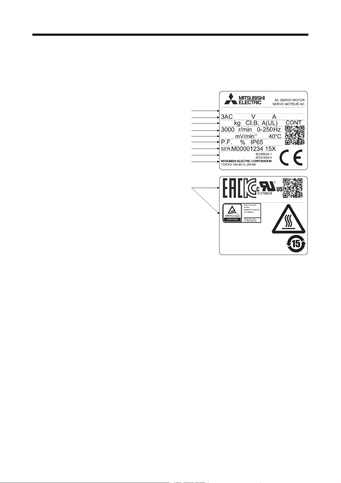
1.1 Rating plate
The following shows an example of rating plate for explanation of each item.
Model
Input power, rated current and rated output
Mass and insulation class
Rated speed
Induced voltage constant and maximum ambient temperature
Power factor and IP rating
Serial number (Note 1)
Country of origin and conforming standards
Manufacturer
0.57
31
MADE IN JAPAN
FABRIQUÉ AU JA PON
HG-KN13J
112 0.8
98
100W
(Note 2)
MSIP-REI-MEK-BSM0060000000A
Note 1. Production year and month of the servo motor are indicated in a serial number on the rating plate.
The year and month are indicated by the last two digits of the year and one digit of the month [1 to 9, X (10),
Y (11), and Z (12)].
For January 2012, the Serial No. is like, "SER. _ _ _ _ _ _ _ _ _ 121".
2. Products approved by Certification Bodies are marked. The marks depends on the Certification Bodies.
1 - 1
1. INTRODUCTION
A
)
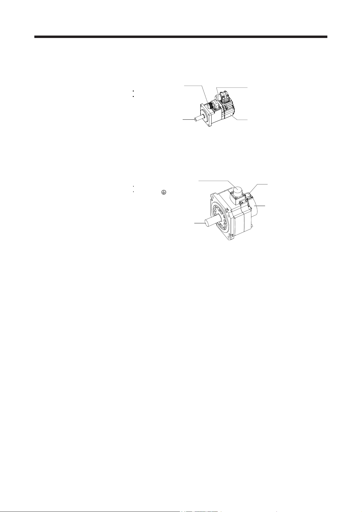
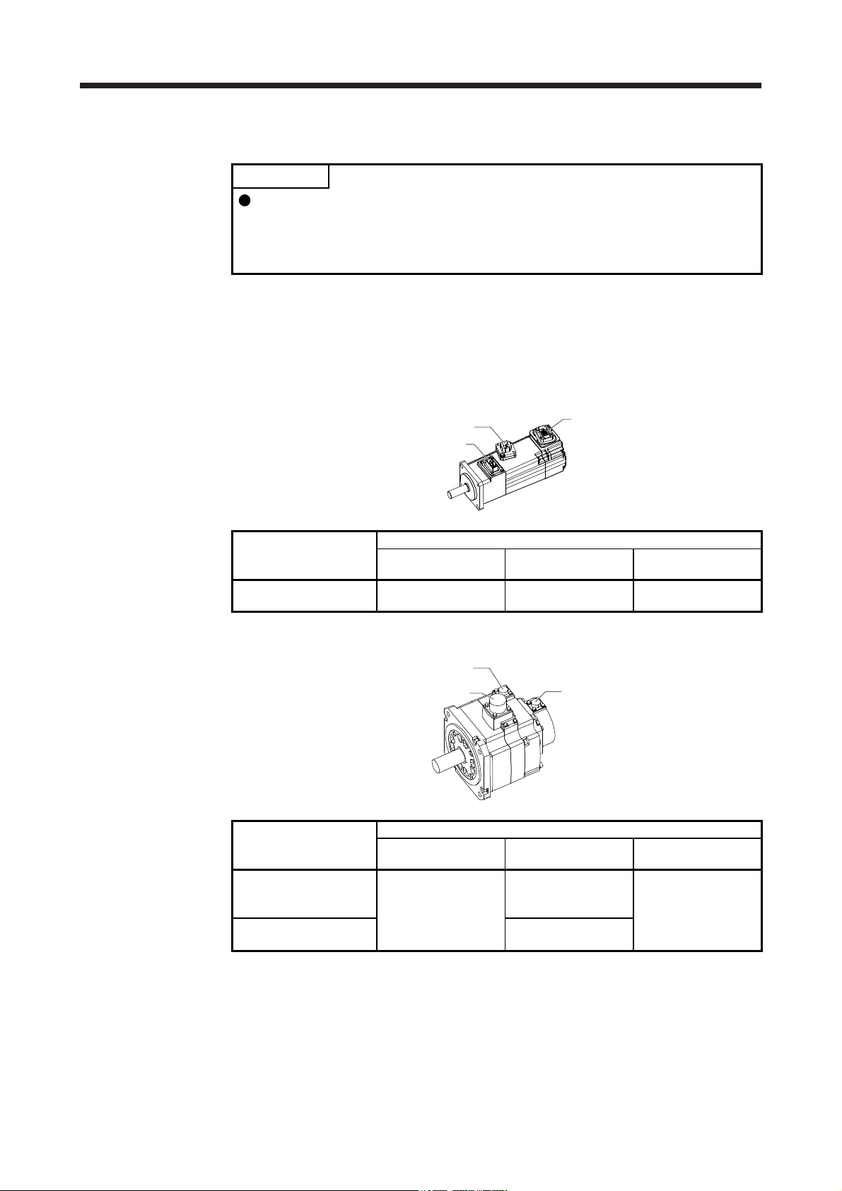
1.2 Parts identification
(1) HG-KN series servo motor
Power cable (Note 1, 2)
Power lead (U/V/W)
Grounding lead
Encoder cable (Note 1)
(2) HG-SN series servo motor
Servo motor shaft
Note 1. The encoder cable and power supply cable are options.
2.
Power supply connector (Note
Power supply (U/V/W)
Grounding ( )
Note. The servo motor with an electromagnetic brake has the electromagnetic brake
n electromagnetic brake cable is separately required for the servo motor with an
electromagnetic brake.
Servo motor shaft
connector separately.
Encoder
Encoder connector
Encoder
1 - 2
1. INTRODUCTION
1.3 Electromagnetic brake
The electromagnetic brake is provided to prevent a drop at a power failure or
alarm occurrence during vertical drive or to hold a shaft at a stop. Do not use it for
normal braking (including braking at servo-lock).
The electromagnetic brake has a time lag. Ensure enough time between releasing
the electromagnetic brake and starting the servo motor. Be sure to check the
operation delay time with an actual machine.
Configure an electromagnetic brake circuit so that it is activated also by an
CAUTION
The servo motor with an electromagnetic brake can be used to prevent a drop in vertical lift applications or to
ensure double safety at an emergency stop, for example. When operating the servo motor, supply power to
the electromagnetic brake to release the brake. Switching power off enables the electromagnetic brake.
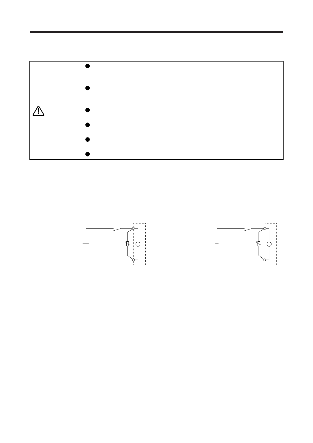
(1) Electromagnetic brake power supply
Prepare the following power supply for use with the electromagnetic brake only. The electromagnetic
brake terminals (B1/B2) have no polarity.
external emergency stop switch.
For details of the circuit configuration and timing chart, refer to each servo
amplifier instruction manual.
While the electromagnetic brake is opened, the motor may be raised to high
temperature regardless of driving.
The life will be shortened under sudden acceleration/deceleration conditions.
B1
B1
24 V DC
power supply for
electromagnetic brake
Switch
VAR
B
U
B2
Electromagnetic brake
24 V DC
or
power supply for
electromagnetic brake
Switch
VAR
U
The surge absorber (VAR) must be installed between B1 and B2. For a selection example of the surge
absorber, refer to "Electromagnetic brake characteristic" in the chapter of each servo motor series.
When you use a diode for a surge absorber, the electromagnetic braking time will be longer.
(2) Sound generation
Though the brake lining may rattle during operation, it poses no functional problem.
If braking sounds, it may be improved by setting the machine resonance suppression filter in the servo
amplifier parameters. For details, refer to each servo amplifier instruction manual.
B2
B
Electromagnetic brake
1 - 3
1. INTRODUCTION
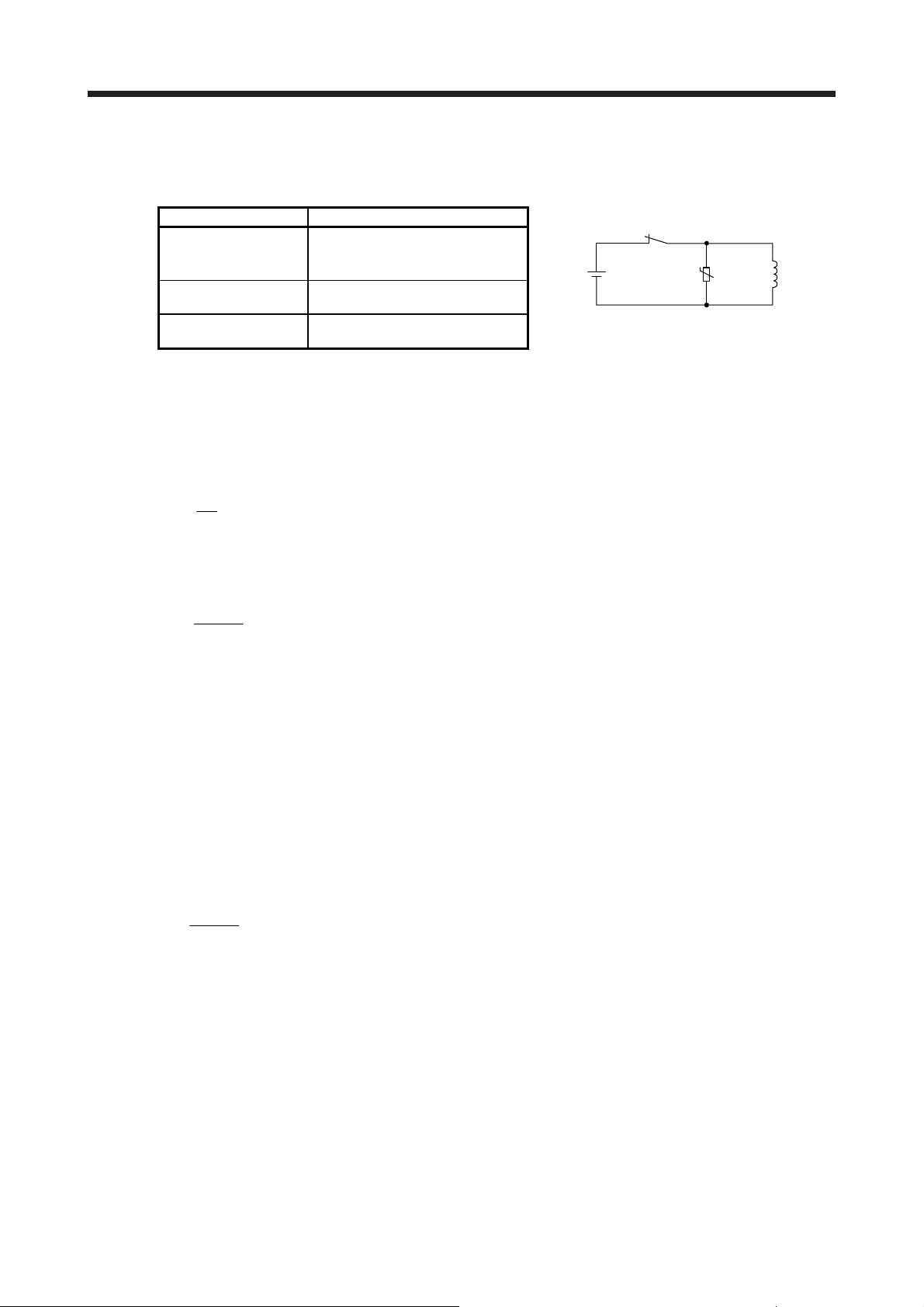
(3) Selection of surge absorbers for electromagnetic brake circuit
The following shows an example how to select a varistor with a surge absorber.
(a) Selection conditions
Electromagnetic brake
specification
Desired suppression
voltage
Durable surge
application time
(b) Tentative selection and verification of surge absorber
1) Maximum allowable circuit voltage of varistor
Tentatively select a varistor whose maximum allowable voltage is larger than Vb [V].
2) Brake current (Ib)
Ib =
3) Energy (E) generated by brake coil
E =
4) Varistor limit voltage (Vi)
From the energy (E) generated in the brake coil and the varistor characteristic diagram, calculate
the varistor limit voltage (Vi) when the brake current (Ib) flows into the tentatively selected varistor
during opening of the circuit.
Vi is favorable when the varistor limit voltage (Vi) [V] is smaller than the desired suppressed
voltage (Vs) [V].
If Vi is not smaller than Vs, reselect a varistor or improve the withstand voltage of devices.
5) Surge current width (τ)
Given that the varistor absorbs all energies, the surge current width (τ) will be as follows.
τ =
6) Examining surge life of varistor
From the varistor characteristic diagram, find the guaranteed current value (Ip) in which the
number of the surge application life is N at the surge current width (τ). Calculate the guaranteed
current value (Ip) ratio to brake current (Ib).
If an enough margin is ensured for Ip/Ib, the number of the surge application life N [time] can be
considered as favorable.
(4) Others
A leakage magnetic flux will occur at the shaft end of the servo motor equipped with an electromagnetic
brake. Note that chips, screws, etc. are attracted.
Item Condition
R [Ω]: Resistance
L [H]: Inductance
Vb [V]: Power supply voltage
Vs [V] or less
N times
Vb
[A]
R
2
L × lb
[J]
2
E
Vi × lb
[S]
Relay
24 V DC
U
Varistor
Brake coil
1 - 4
1. INTRODUCTION
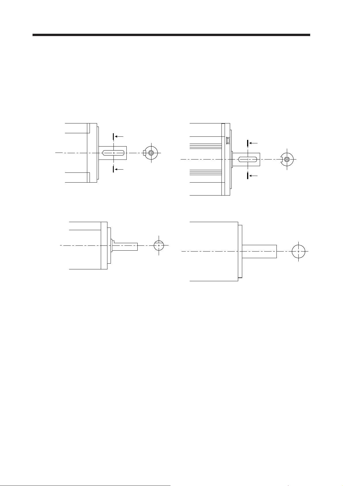
1.4 Servo motor shaft shapes
In addition to the straight shaft, the key shaft and D cut shaft are available.
The key shaft and D cut shaft cannot be used in very frequent start/stop applications.
Since we cannot warrant the servo motor against fracture and similar accidents attributable to a loose key,
use a friction coupling, etc. when coupling the shaft with a machine.
The shaft shape of the standard servo motor changes depending on the series and capacity. Refer to the
chapter of the servo motor series.
A
A
A
Shaft section view AA
A
Shaft section view AA
Key shaft (with 2 round end key) Key shaft (without key)
D cut shaft Straight shaft
1 - 5
1. INTRODUCTION
MEMO
1 - 6
2. INSTALLATION
2. INSTALLATION
WARNING
CAUTION
To prevent electric shock, ground each equipment securely.
Stacking in excess of the specified number of product packages is not allowed.
Install the equipment on incombustible material. Installing them directly or close to
combustibles will lead to smoke or a fire.
Install the servo motor in a load-bearing place in accordance with the Instruction
Manual.
Do not get on or put heavy load on the equipment. Otherwise, it may cause injury.
Use the equipment within the specified environment. For the environment, refer to
the specifications of the servo motor series.
Do not drop or strike the servo motor. Isolate it from all impact loads.
Do not install or operate a faulty servo motor.
Do not carry the servo motor by holding the cables, connectors, shaft, or encoder.
Otherwise, it may drop.
Securely fix the servo motor to the machine. If being attached insecurely, the
motor may come off during operation, leading to injury.
Be sure to measure the vibration level with the servo motor mounted on the
machine when checking the vibration level. A great vibration may cause the early
damage to a bearing, encoder, and brake. The great vibration may also cause the
poor connector connection or bolt looseness.
For the gain adjustment at the equipment startup, check the torque waveform and
the speed waveform with a measurement device to check that no vibration
occurs. If the vibration occurs due to high gain, the vibration may cause the early
damage to the servo motor.
Never hit the servo motor or shaft, especially when coupling the servo motor to
the machine. Otherwise, the encoder may malfunction.
When coupling a load to the servo motor, do not use a rigid coupling. Doing so
can cause the shaft to break and the bearing to wear out.
Balance the load to the extent possible. Not doing so can cause vibration during
servo motor operation or damage the bearings and encoder.
Take safety measures, e.g. provide covers, to prevent accidental access to the
rotor of the servo motor during operation.
Do not subject the servo motor shaft to more than the permissible load.
Otherwise, the shaft may break, leading to injury.
When the product has been stored for an extended period of time, contact your
local sales office.
When handling the servo motor, be careful with the sharp edges of the servo
motor, shaft keyway, or others.
Do not use the servo motor where the shaft-through portion may be subject to
pressure (e.g. compressed air). Applying air pressure to the inside of the servo
motor may cause a malfunction.
2 - 1
2. INSTALLATION
2.1 Mounting direction
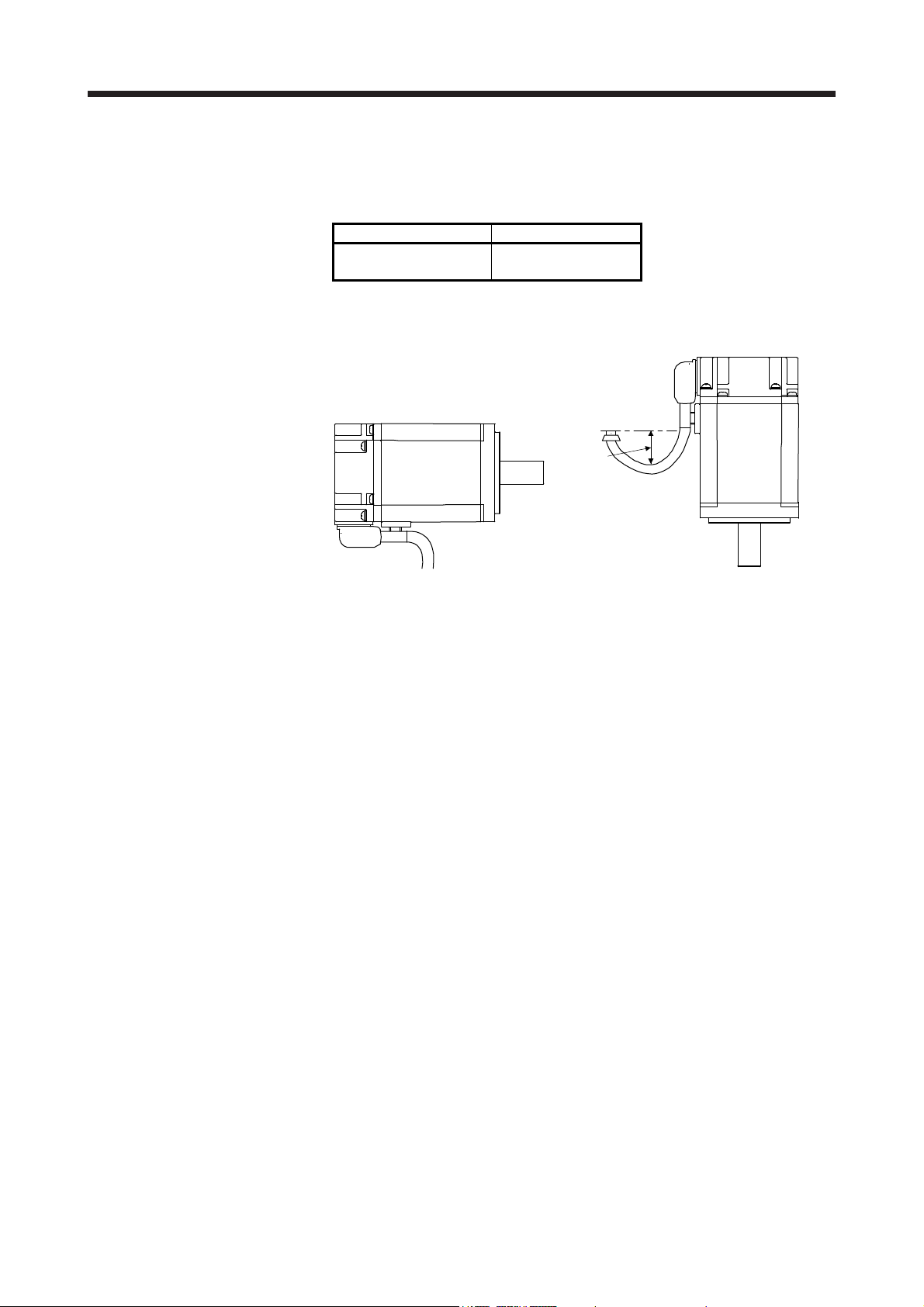
(1) Standard servo motor
The following table indicates the mounting direction of the standard servo motor.
For mounting in the horizontal direction, it is recommended to set the connector section downward.
When mounting the motor vertically or obliquely, give a little slack for the connection cable.
Servo motor series Mounting direction
HG-KN
HG-SN
All direction
Little slack
(2) Servo motor with an electromagnetic brake
The servo motor with an electromagnetic brake can also be installed in the same orientation as the
standard servo motor. When the servo motor with an electromagnetic brake is installed with the shaft
end at top, the brake plate may generate sliding sound but it is not a fault.
2 - 2
2. INSTALLATION
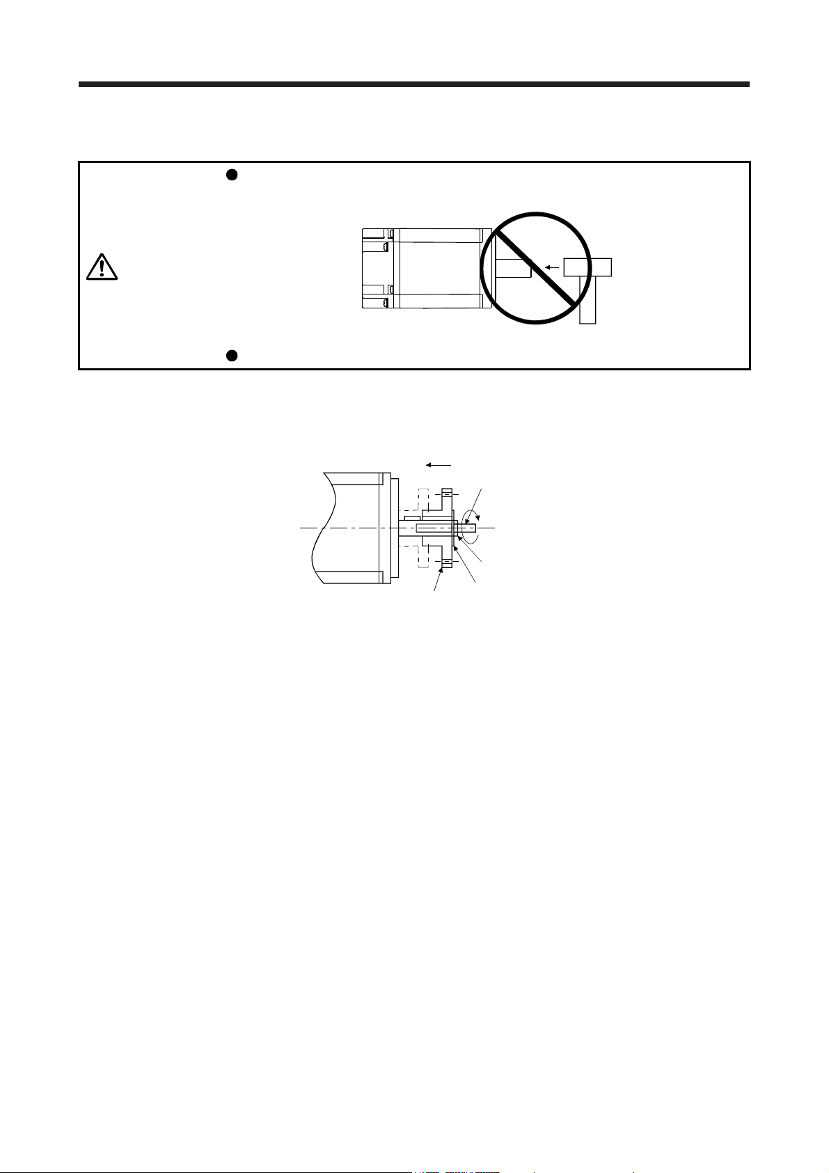
2.2 Load mounting/dismounting precautions
During assembling, the shaft end must not be hammered. Otherwise, the encoder
may malfunction.
CAUTION
Do not process the shaft to avoid damage to the encoder and bearing.
(1) When mounting a pulley to the servo motor with a key shaft, use the screw hole in the shaft end. To fit
the pulley, first insert a double-end stud into the screw hole of the shaft, put a washer against the end
face of the coupling, and insert and tighten a nut to force the pulley in.
Servo motor
Double-end stud
Nut
Pulley
Washer
(2) For the shaft without a key, use a friction coupling or the like.
(3) When removing the pulley, use a pulley remover to protect the shaft from hard load and or impact.
(4) To ensure safety, fit a protective cover or the like on the rotary area, such as the pulley, mounted to the
shaft.
(5) When a threaded shaft end part is needed to mount a pulley on the shaft, please contact your local sales
office.
(6) The direction of the encoder on the servo motor cannot be changed.
(7) When mounting the servo motor, use spring washers, etc. and fully tighten the bolts so that they do not
become loose due to vibration.
2 - 3
2. INSTALLATION
2.3 Permissible load for the shaft
CAUTION
For the permissible shaft load specific to the servo motor, refer to the chapter of the servo motor series.
(1) Use a flexible coupling and adjust the misalignment of the shaft to less than the permissible radial load.
(2) When using a pulley, sprocket, or timing belt, keep the radial load within the permissible value.
(3) Excess of the permissible load can cause the bearing life to reduce and the shaft to break.
(4) The load indicated in this section is static load in a single direction and does not include eccentric load.
Make eccentric load as small as possible. Not doing so can cause the servo motor to be damaged.
2.4 Protection from oil and water
Do not use a rigid coupling as it may apply excessive bending load to the shaft of
the servo motor, leading the shaft to break and the bearing to wear out.
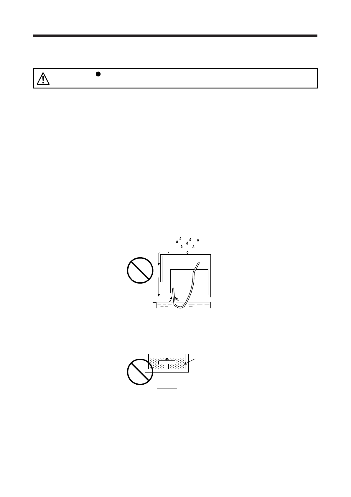
Provide adequate protection to prevent foreign matter, such as oil from entering the servo motor shaft. When
installing the servo motor, consider the items in this section.
(1) Do not use the direct drive motor with its cable soaked in oil or water.
Cover
Servo
motor
Oil/water pool
Capillary action
(2) When the servo motor is to be installed with the shaft end at top, provide measures so that it is not
exposed to oil and water entering from the machine side, gear box, etc.
Gear
Lubricating oil
Servo motor
(3) If oil such as cutting oil drops on the servo motor, the sealant, packing, cable and others may be affected
depending on the oil type.
(4) In the environment where the servo motor is exposed to oil mist, oil, water, grease and/or like, a
standard specifications servo motor may not be usable. Please contact your local sales office.
2 - 4

2. INSTALLATION
2.5 Cable
The power supply and encoder cables routed from the servo motor should be fixed to the servo motor to
keep them unmovable. Otherwise, the cable may disconnect. In addition, do not modify the connectors,
terminals and others at the ends of the cables.
2.6 Servo motor with oil seal
For the servo motor with oil seal, the oil seal prevents the entry of oil into the servo motor. Make sure to
install it according in this section.
The functions have no problem even if the servo motor with oil seal may sound during operation.
(1) Pressure and oil level
Install the servo motor horizontally, and set the oil level in the gear box to be lower than the oil seal lip
always. If the oil level is higher than the oil seal lip, the oil enter the servo motor and may cause a
malfunction. Refer to the chapter of the servo motor series for the height above oil level.
Shaft
Gear
Servo motor
Height above oil level h
Lip
Oil seal
High pressure against the oil seal causes the abrasion and makes the life be short. Keep constant
internal pressure by equipping a ventilator to the gear box.
(2) Temperature
High temperature against the oil seal lip makes the life be short. Avoid exposing the oil seal lip to high
temperature oil since applicable temperature of the material is up to 100 °C and temperature of the oil
seal lip rises within 10 °C to 15 °C at maximum rotation.
2 - 5
2. INSTALLATION
2.7 Inspection items
Before starting maintenance and/or inspection, turn off the power and wait for 15
minutes or more until the charge lamp turns off. Otherwise, an electric shock may
WARNING
CAUTION
It is recommended that the following points periodically be checked.
(1) Check the bearings, brake section, etc. for unusual noise.
(2) Check the cables and the like for scratches or cracks. Especially when the cable is movable, perform
periodic inspections according to operating conditions.
(3) Check the servo motor shaft and coupling for misalignment.
(4) Check the power connector and encoder connector tightening screws for looseness.
2.8 Parts having service life
occur. In addition, when confirming whether the charge lamp is off or not, always
confirm it from the front of the servo amplifier.
To avoid an electric shock, only qualified personnel should attempt inspections.
For repair and parts replacement, contact your local sales office.
Do not perform insulation resistance test on the servo motor. Otherwise, it may
cause a malfunction.
Do not disassemble and/or repair the equipment on customer side.
Service life of the following parts is listed below. However, the service life varies depending on operating
methods and environment. If any fault is found in the parts, they must be replaced immediately regardless of
their service life. For parts replacement, please contact your local sales office.
Part name Life guideline
Bearings
Encoder
Oil seal 5000 hours
20,000 hours to
30,000 hours
20,000 hours to
30,000 hours
(1) Bearings
When the motor is run at rated speed under rated load, bearings should be exchanged in 20,000 to
30,000 hours as a guideline. This differs on the operating conditions. The bearings must also be
changed if unusual noise or vibration is found during inspection.
(2) Oil seal
Oil seals must be changed in 5,000 hours of operation at rated speed as a guideline. They must also be
changed if oil leakage, etc. is found during inspection.
The functions have no problem even if an oil seal may sound during operation.
2 - 6
2. INSTALLATION
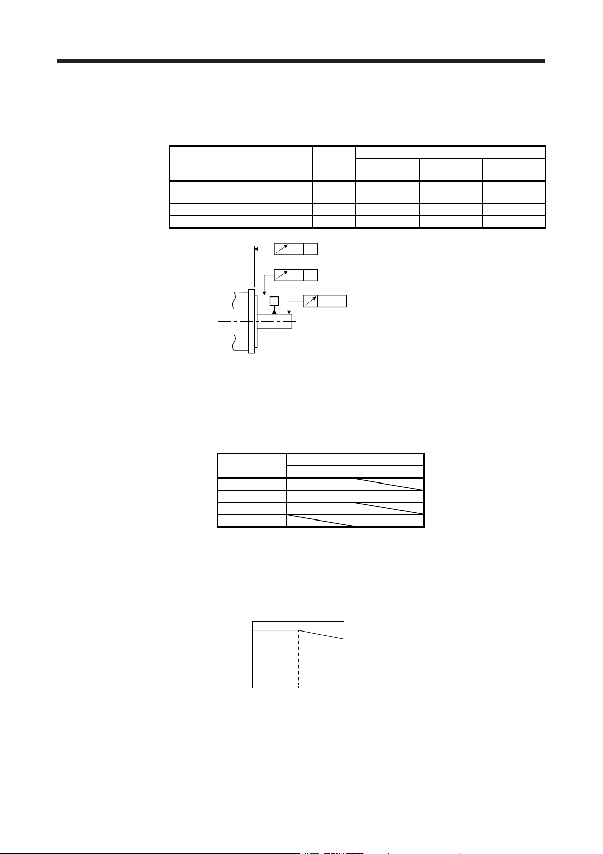
2.9 Machine accuracies
The following table indicates the machine accuracies of the servo motor around the output shaft and
mounting. (except the optional products)
Accuracy [mm]
Runout of flange surface to output
shaft
Runout of fitting OD of flange surface b) 0.04 0.04 0.06
Runout of output shaft end c) 0.02 0.02 0.03
Measuring
position
a) 0.05 0.06 0.08
100 × 100
or less
a)
A
b)
A
A
c)
Flange size
130 × 130 176 × 176
2.10 Mounting servo motors
Be sure to use the servo motor within the specified environment, and mount the servo motor on a machine
having the equivalent heat dissipation effect as the following aluminum flange.
The temperature of the servo motor increases differently depending on its mounting environment, operating
conditions, etc. Make sure to check the temperature with an actual machine.
Flange size [mm]
250 × 250 × 6 13/23
250 × 250 × 12 43 52/102/152
300 × 300 × 12 73
300 × 300 × 20 202/302
Servo motor
HG-KN HG-SN
2.11 Restrictions when using the equipment at altitudes exceeding 1000 m and up to 2000 m above sea level
As heat dissipation effects decrease in proportion to decreasing air density, use the equipment within the
effective load ratio and regenerative load ratio shown in the following figure.
[%]
100
95
Effective load ratio
0
0
Regenerative load ratio
Altitude
[m]
20001000
2 - 7
2. INSTALLATION
MEMO
2 - 8
3. CONNECTORS USED FOR SERVO MOTOR WIRING
r
3. CONNECTORS USED FOR SERVO MOTOR WIRING
POINT
The IP rating indicated is the connector's protection against ingress of dust and
water when the connector is connected to a servo motor. If the IP rating of the
connector, and servo motor vary, the overall IP rating depends on the lowest IP
rating of all components.
3.1 Selection of connectors
Use the connector configuration products given in the table as the connectors for connection with the servo
motor. Refer to section 3.2 and 3.3 for the compatible connector configuration products.
(1) HG-KN series
Electromagnetic brake connector
Power supply connector
Encoder connector
Wiring connector
Servo motor
HG-KN_
For encoder For power supply
Connector
configuration A
Connector
configuration B
For electromagnetic
brake
Connector
configuration C
(2) HG-SN series
Electromagnetic brake connecto
Power supply connector
Encoder connector
Wiring connector
Servo motor
HG-SN52
HG-SN102
HG-SN152
HG-SN202
HG-SN302
For encoder For power supply
Connector
Connector
configuration D
configuration E
Connector
configuration G
For electromagnetic
brake
Connector
configuration F
3 - 1
3. CONNECTORS USED FOR SERVO MOTOR WIRING
3.2 Wiring connectors (connector configurations A/B/C)
Connector
configuration
A
(for encoder)
Feature Connector Crimping tool
Connector: 2174053-1
IP65
(TE Connectivity)
Note. The connector to be mated.
Connector
configuration
B
(for power
supply)
Feature Connector Crimping tool
Connector: KN4FT04SJ1-R
HOOD/SOCKET
INSULATOR/BUSHING/GROUND NUT
IP65
Contact: ST-TMH-S-C1B-100 (A534G)
(JAE)
Note. The connector to be mated.
For ground clip: 1596970-1
For receptacle contact: 1596847-1
(TE Connectivity)
CT170-14-TMH5B
(JAE)
Servo motor encoder
connector (Note)
1674339-1
(TE Connectivity)
Servo motor power
connector (Note)
JN4AT04NJ1
(JAE)
Connector
configuration
C
(for
electromagnetic
brake)
Feature Connector Crimping tool
Connector: JN4FT02SJ1-R
HOOD/SOCKET
INSULATOR/BUSHING/GROUND NUT
IP65
Contact: ST-TMH-S-C1B-100 (A534G)
(JAE)
Note. The connector to be mated.
CT170-14-TMH5B
(JAE)
Servo motor
electromagnetic brake
connector (Note)
JN4AT02PJ1
(JAE)
3 - 2
3. CONNECTORS USED FOR SERVO MOTOR WIRING
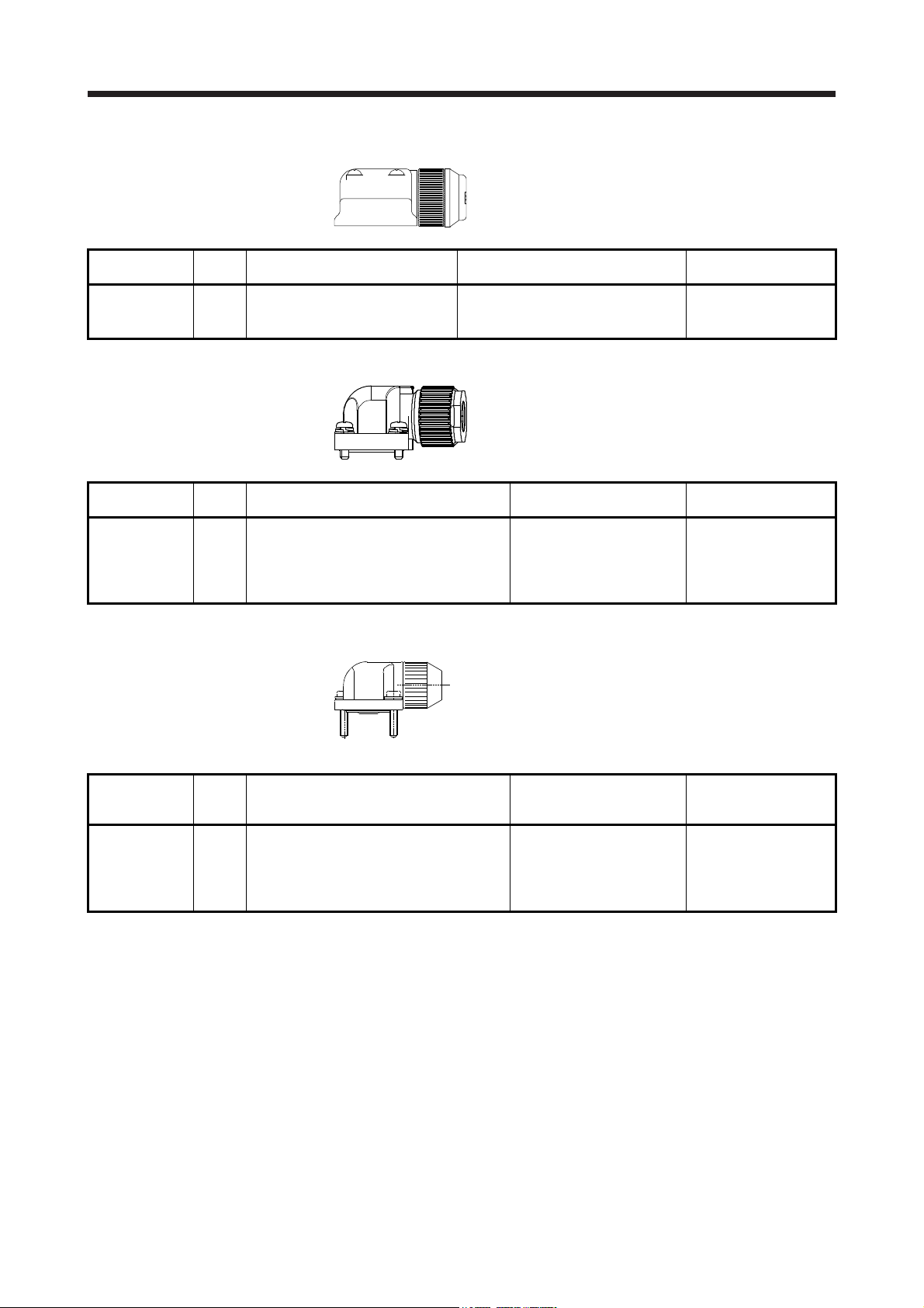
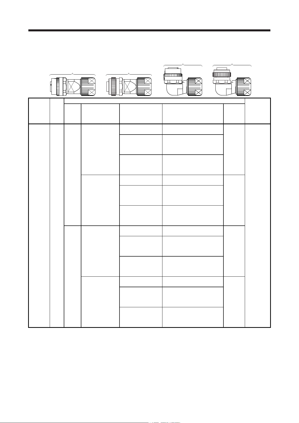
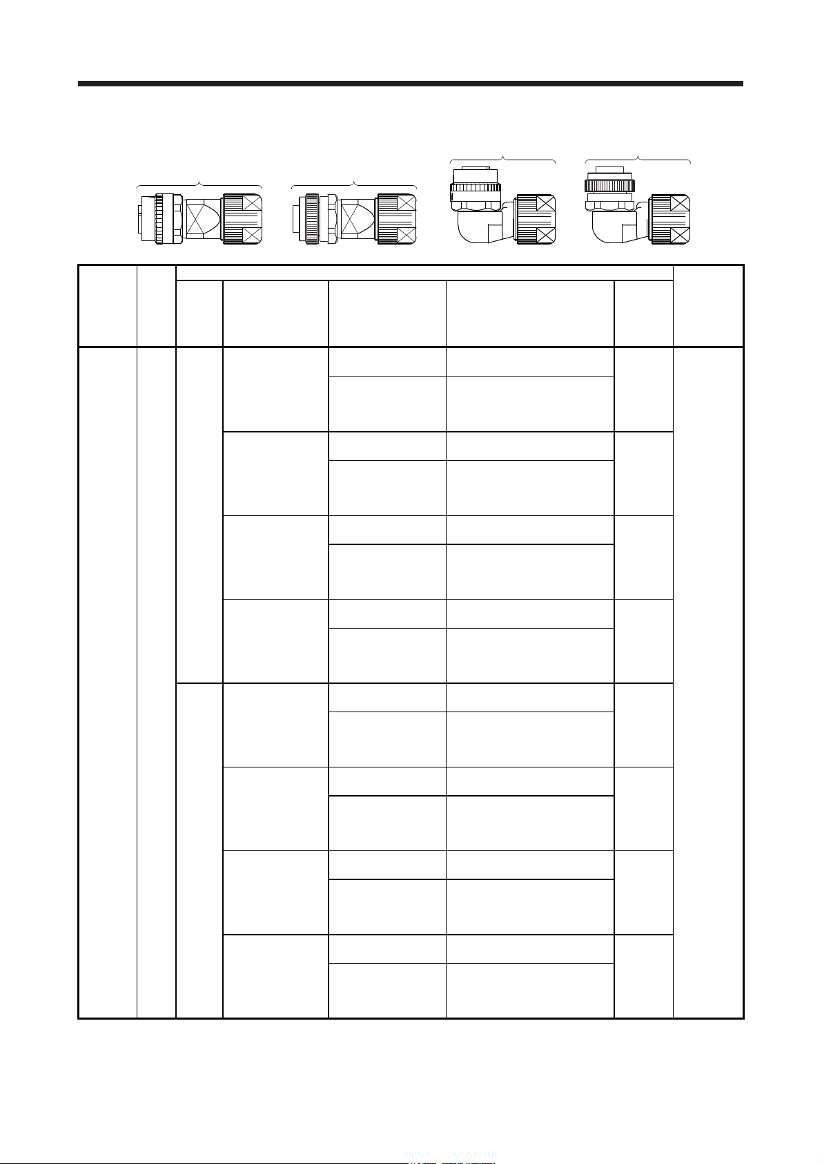
3.3 Wiring connectors (connector configurations D/E/F/G)
Angle plug
Straight plug
(one-touch connection type)
Straight plug
(screw type)
(one-touch connection type)
Angle plug
(screw type)
Connector
configuration
(for encoder)
Feature
D
IP67
Type Plug Socket contact Contact shape
CMV1-SP10S-M1
(one-touch connection
type)
CMV1S-SP10S-M1
(screw type)
Straight
CMV1-SP10S-M2
(one-touch connection
type)
CMV1S-SP10S-M2
(screw type)
CMV1-AP10S-M1
(one-touch connection
type)
CMV1S-AP10S-M1
(screw type)
Angle
CMV1-AP10S-M2
(one-touch connection
type)
CMV1S-AP10S-M2
(screw type)
Note. The connector to be mated.
Plug (DDK)
CMV1-#22ASC-S1-100
CMV1-#22ASC-C1-100
CMV1-#22ASC-C2-100
CMV1-#22ASC-S1-100
CMV1-#22ASC-C1-100
CMV1-#22ASC-C2-100
CMV1-#22ASC-S1-100
CMV1-#22ASC-C1-100
CMV1-#22ASC-C2-100
CMV1-#22ASC-S1-100
CMV1-#22ASC-C1-100
CMV1-#22ASC-C2-100
Soldering type
Applicable wire size: AWG 20 or less
Crimping type
Applicable wire size: AWG 24 to 20
The crimping tool (357J-53162T)
is required.
Crimping type
Applicable wire size: AWG 28 to 24
The crimping tool (357J-53163T)
is required.
Soldering type
Applicable wire size: AWG 20 or less
Crimping type
Applicable wire size: AWG 24 to 20
The crimping tool (357J-53162T)
is required.
Crimping type
Applicable wire size: AWG 28 to 24
The crimping tool (357J-53163T)
is required.
Soldering type
Applicable wire size: AWG 20 or less
Crimping type
Applicable wire size: AWG 24 to 20
The crimping tool (357J-53162T)
is required.
Crimping type
Applicable wire size: AWG 28 to 24
The crimping tool (357J-53163T)
is required.
Soldering type
Applicable wire size: AWG 20 or less
Crimping type
Applicable wire size: AWG 24 to 20
The crimping tool (357J-53162T)
is required.
Crimping type
Applicable wire size: AWG 28 to 24
The crimping tool (357J-53163T)
is required.
Cable
OD
[mm]
(reference)
5.5 to 7.5
7.0 to 9.0
5.5 to 7.5
7.0 to 9.0
Servo motor
encoder
connector
(Note)
CMV1-R10P
3 - 3
3. CONNECTORS USED FOR SERVO MOTOR WIRING
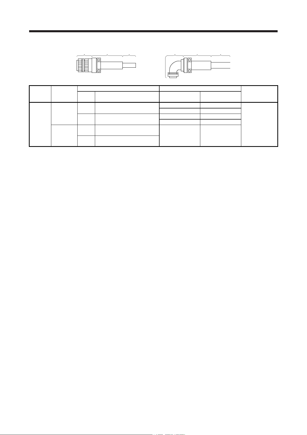
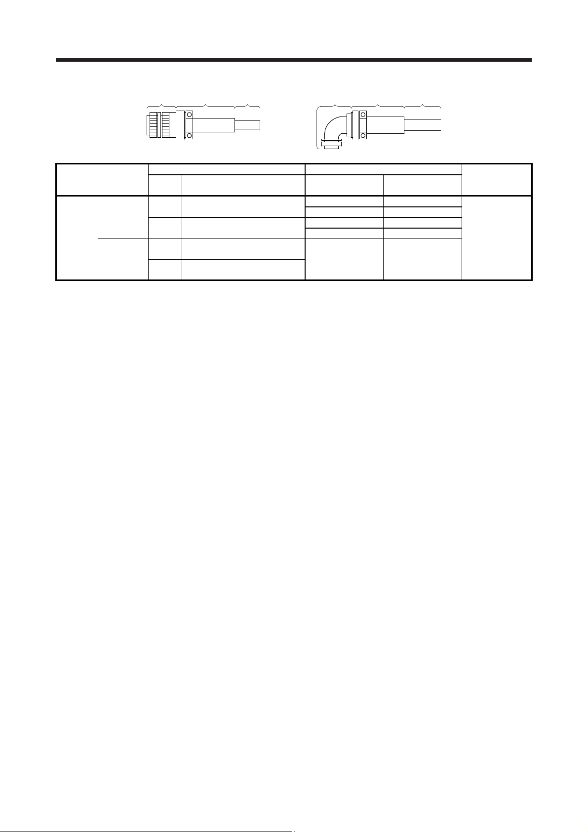
Plug Cable clamp Cable Plug Cable clamp Cable
Connector
configuration
E
(for power
supply)
Feature
IP67
EN compliant
(Note 1)
General
environment
Type Model
Straight
Angle
Straight
Angle
Note 1. Not comply with EN.
2. The connector to be mated.
Plug (DDK) Cable clamp (DDK)
Cable OD
[mm] (reference)
CE05-6A18-10SD-D-BSS
Applicable wire size: AWG 14 to 12
CE05-8A18-10SD-D-BAS
Applicable wire size: AWG 14 to 12
D/MS3106B18-10S
Applicable wire size: AWG 14 to 12
D/MS3108B18-10S
Applicable wire size: AWG 14 to 12
8.5 to 11 CE3057-10A-2-D
10.5 to 14.1 CE3057-10A-1-D
8.5 to 11 CE3057-10A-2-D
10.5 to 14.1 CE3057-10A-1-D
14.3 or less
(bushing ID)
Model
D/MS3057-10A
Servo motor
power connector
(Note 2)
MS3102A18-10P
3 - 4
3. CONNECTORS USED FOR SERVO MOTOR WIRING
Angle plug
Soldering type
Applicable wire size: AWG 16 or less
Crimping type
Applicable wire size: AWG 20 to 16
The crimping tool (357J-53164T) is
required.
Soldering type
Applicable wire size: AWG 16 or less
Crimping type
Applicable wire size: AWG 20 to 16
The crimping tool (357J-53164T) is
required.
Soldering type
Applicable wire size: AWG 16 or less
Crimping type
Applicable wire size: AWG 20 to 16
The crimping tool (357J-53164T) is
required.
Soldering type
Applicable wire size: AWG 16 or less
Crimping type
Applicable wire size: AWG 20 to 16
The crimping tool (357J-53164T) is
required.
Soldering type
Applicable wire size: AWG 16 or less
Crimping type
Applicable wire size: AWG 20 to 16
The crimping tool (357J-53164T) is
required.
Soldering type
Applicable wire size: AWG 16 or less
Crimping type
Applicable wire size: AWG 20 to 16
The crimping tool (357J-53164T) is
required.
Soldering type
Applicable wire size: AWG 16 or less
Crimping type
Applicable wire size: AWG 20 to 16
The crimping tool (357J-53164T) is
required.
Soldering type
Applicable wire size: AWG 16 or less
Crimping type
Applicable wire size: AWG 20 to 16
The crimping tool (357J-53164T) is
required.
Straight plug
(one-touch connection type)
Connector
configuration
electro-
magnetic
brake)
F
(for
Feature
IP67
Type Plug Socket contact Contact shape
CMV1-SP2S-S
(one-touch connection
type)
CMV1S-SP2S-S
(screw type)
CMV1-SP2S-M1
(one-touch connection
type)
CMV1S-SP2S-M1
(screw type)
Straight
CMV1-SP2S-M2
(one-touch connection
type)
CMV1S-SP2S-M2
(screw type)
CMV1-SP2S-L
(one-touch connection
type)
CMV1S-SP2S-L
(screw type)
CMV1-AP2S-S
(one-touch connection
type)
CMV1S-AP2S-S
(screw type)
CMV1-AP2S-M1
(one-touch connection
type)
CMV1S-AP2S-M1
(screw type)
Angle
CMV1-AP2S-M2
(one-touch connection
type)
CMV1S-AP2S-M2
(screw type)
CMV1-AP2S-L
(one-touch connection
type)
CMV1S-AP2S-L
(screw type)
Note. The connector to be mated.
Straight plug
(screw type)
Plug (DDK) Servo motor
CMV1-#22BSC-S2-100
CMV1-#22BSC-C3-100
CMV1-#22BSC-S2-100
CMV1-#22BSC-C3-100
CMV1-#22BSC-S2-100
CMV1-#22BSC-C3-100
CMV1-#22BSC-S2-100
CMV1-#22BSC-C3-100
CMV1-#22BSC-S2-100
CMV1-#22BSC-C3-100
CMV1-#22BSC-S2-100
CMV1-#22BSC-C3-100
CMV1-#22BSC-S2-100
CMV1-#22BSC-C3-100
CMV1-#22BSC-S2-100
CMV1-#22BSC-C3-100
(one-touch connection type)
Angle plug
(screw type)
Cable
OD
[mm]
(reference)
4.0 to 6.0
5.5 to 7.5
7.0 to 9.0
9.0 to 11.6
4.0 to 6.0
5.5 to 7.5
7.0 to 9.0
9.0 to 11.6
electro-
magnetic
brake
connector
(Note)
CMV1-R2P
3 - 5
3. CONNECTORS USED FOR SERVO MOTOR WIRING
Plug Cable clamp Cable Plug Cable clamp Cable
Connector
configuration
G
(for power
supply)
Feature
IP67
EN compliant
(Note 1)
General
environment
Type Model
Straight
Angle
Straight
Angle
Note 1. Not comply with EN.
2. The connector to be mated.
Plug (DDK) Cable clamp (DDK)
Cable OD
[mm] (reference)
CE05-6A22-22SD-D-BSS
Applicable wire size: AWG 10 to 8
CE05-8A22-22SD-D-BAS
Applicable wire size: AWG 10 to 8
D/MS3106B22-22S
Applicable wire size: AWG 10 to 8
D/MS3108B22-22S
Applicable wire size: AWG 10 to 8
9.5 to 13 CE3057-12A-2-D
12.5 to 16 CE3057-12A-1-D
9.5 to 13 CE3057-12A-2-D
12.5 to 16 CE3057-12A-1-D
15.9 or less
(bushing ID)
Model
D/MS3057-12A
Servo motor
power connector
(Note 2)
MS3102A22-22P
3 - 6
4. CONNECTION OF SERVO AMPLIFIER AND SERVO MOTOR
4. CONNECTION OF SERVO AMPLIFIER AND SERVO MOTOR
Any person who is involved in wiring should be fully competent to do the work.
Ground the servo motor securely.
Do not attempt to wire the servo motor until it has been mounted. Otherwise, it
WARNING
CAUTION
may cause an electric shock.
The cables should not be damaged, stressed, loaded, or pinched. Otherwise, it
may cause an electric shock.
To avoid an electric shock, insulate the connections of the power supply
terminals.
Wire the equipment correctly and securely. Otherwise, the servo motor may
operate unexpectedly, resulting in injury.
Connect cables to the correct terminals. Otherwise, a burst, damage, etc. may
occur.
Ensure that polarity (+/-) is correct. Otherwise, a burst, damage, etc. may occur.
Do not install a power capacitor, surge killer or radio noise filter (optional FR-BIF)
with the power line of the servo motor.
Do not modify the equipment.
Connect the servo amplifier power output (U/V/W) to the servo motor power input
(U/V/W) directly. Do not let a magnetic contactor, etc. intervene. Otherwise, it may
cause a malfunction.
Servo amplifier
U
V
W
Servo motor
U
V
W
Servo motorServo amplifier
U
M
V
W
U
V
W
M
Before wiring, switch operation, etc., eliminate static electricity. Otherwise, it may
cause a malfunction.
4 - 1
 Loading...