


General-Purpose AC Servo
MODEL
HG-MR
HG-KR
HG-SR
HG-JR
HG-RR
HG-UR
HG-AK
SERVO MOTOR INSTRUCTION MANUAL (Vol. 3)
J
Safety Instructions
Please read the instructions carefully before using the equipment.
Do not attempt to install, operate, maintain or inspect the equipment until you have read through this
Instruction Manual and appended documents carefully and can use the equipment correctly. Do not use the
equipment until you have a full knowledge of the equipment, safety information and instructions.
In this Instruction Manual, the safety instruction levels are classified into "WARNING" and "CAUTION".
WARNING
CAUTION
Note that the CAUTION level may lead to a serious consequence according to conditions.
Please follow the instructions of both levels because they are important to personnel safety.
What must not be done and what must be done are indicated by the following diagrammatic symbols.
Indicates that incorrect handling may cause hazardous conditions,
resulting in death or severe injury.
Indicates that incorrect handling may cause hazardous conditions,
resulting in medium or slight injury to personnel or may cause physical
damage.
Indicates what must not be done. For example, "No Fire" is indicated by .
Indicates what must be done. For example, grounding is indicated by .
In this Instruction Manual, instructions at a lower level than the above, instructions for other functions, and so
on are classified into "POINT".
After reading this Instruction Manual, keep it accessible to the operator.
A - 1
1. To prevent electric shock, note the following
WARNING
Before wiring and inspections, turn off the power and wait for 15 minutes or more (20 minutes or more for
converter unit and drive unit) until the charge lamp turns off. Then, confirm that the voltage between P+
and N- (L+ and L- for converter unit and drive unit) is safe with a voltage tester and others. Otherwise, an
electric shock may occur. In addition, when confirming whether the charge lamp is off or not, always
confirm it from the front of the servo amplifier (converter unit).
Ground the servo motor securely.
Any person who is involved in wiring and inspection should be fully competent to do the work.
Do not attempt to wire the servo motor until they have been installed. Otherwise, it may cause an electric
shock.
The cables should not be damaged, stressed, loaded, or pinched. Otherwise, it may cause an electric
shock.
To avoid an electric shock, insulate the connections of the power supply terminals.
2. To prevent fire, note the following
CAUTION
Install the servo motor on incombustible material. Installing it directly or close to combustibles will lead to
a fire.
Provide an adequate protection to prevent screws and other conductive matter, oil and other combustible
matter from entering the servo motor.
3. To prevent injury, note the following
CAUTION
Only the voltage specified in the Instruction Manual should be applied to each terminal. Otherwise, a
burst, damage, etc. may occur.
Connect cables to the correct terminals. Otherwise, a burst, damage, etc. may occur.
Ensure that polarity (+/-) is correct. Otherwise, a burst, damage, etc. may occur.
The servo motor, etc. may be hot while power is on or for some time after power-off. Take safety
measures, e.g. provide covers, to prevent accidental contact of hands and parts (cables, etc.) with them.
The surface temperature of the servo motor may exceed 100 ˚C depending on its mounting and
operating conditions.
During operation, never touch the rotor of the servo motor. Otherwise, it may cause injury.
4. Additional instructions
The following instructions should also be fully noted. Incorrect handling may cause a malfunction, injury,
electric shock, etc.
(1) Transportation and installation
CAUTION
Transport the products correctly according to their mass.
Use the eyebolt of the servo motor for the transportation purpose only. Do not use the eyebolts to
transport the servo motor when it is mounted on a machine.
A - 2
CAUTION
Stacking in excess of the specified number of product packages is not allowed.
Do not carry the servo motor by holding the cables, shaft, encoder, or connector.
Install the servo motor in a load-bearing place in accordance with the Instruction Manual.
Do not get on or put heavy load on the equipment.
The equipment must be installed in the specified direction.
Do not install or operate the servo motor which have been damaged or have any parts missing.
Do not block intake and exhaust areas of the servo motor with a cooling fan. Otherwise, it may cause a
malfunction.
Do not drop or strike the servo motor. Isolate it from all impact loads.
Securely fix the servo motor to the machine. If being attached insecurely, the servo motor may come off
during operation.
The geared servo motor must be installed in the specified direction to prevent oil leakage.
When handling the servo motor, be careful about the edged parts such as the corners of the servo motor.
Be sure to measure the motor vibration level with the servo motor mounted to the machine when
checking the vibration level. A great vibration may cause the early damage of a bearing, encoder, brake,
and reducer. The great vibration may also cause the poor connector connection or bolt looseness.
For the gain adjustment at the equipment startup, check the torque waveform and the speed waveform
with a measurement device, and then check that no vibration occurs. If the vibration occurs due to high
gain, the vibration may cause the early damage of the servo motor.
Take safety measures, e.g. provide covers, to prevent accidental access to the rotor of the servo motor
during operation.
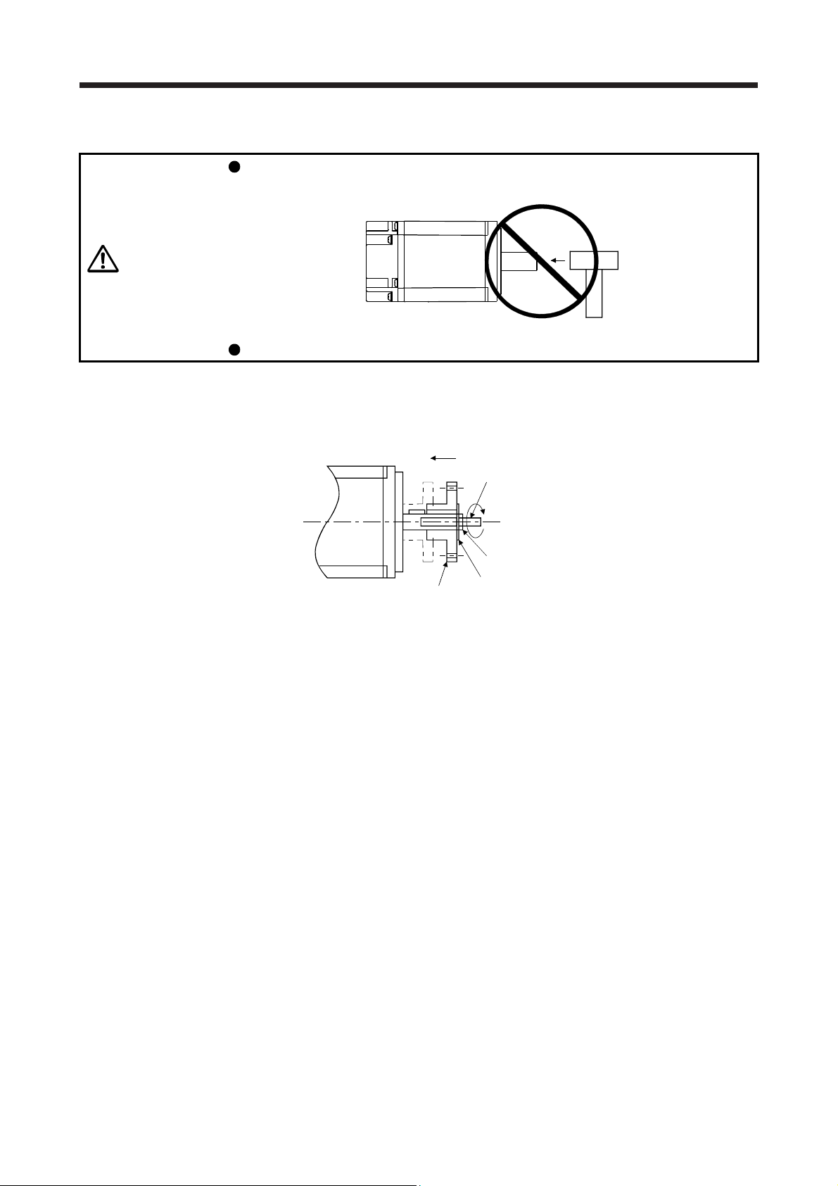
Never hit the servo motor or shaft, especially when coupling the servo motor to the machine. Otherwise,
the encoder may malfunction.
Do not subject the servo motor shaft to more than the permissible load. Otherwise, the shaft may break.
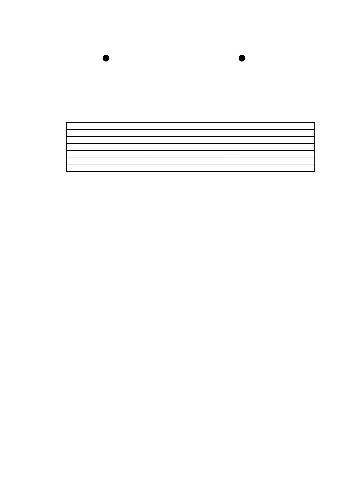
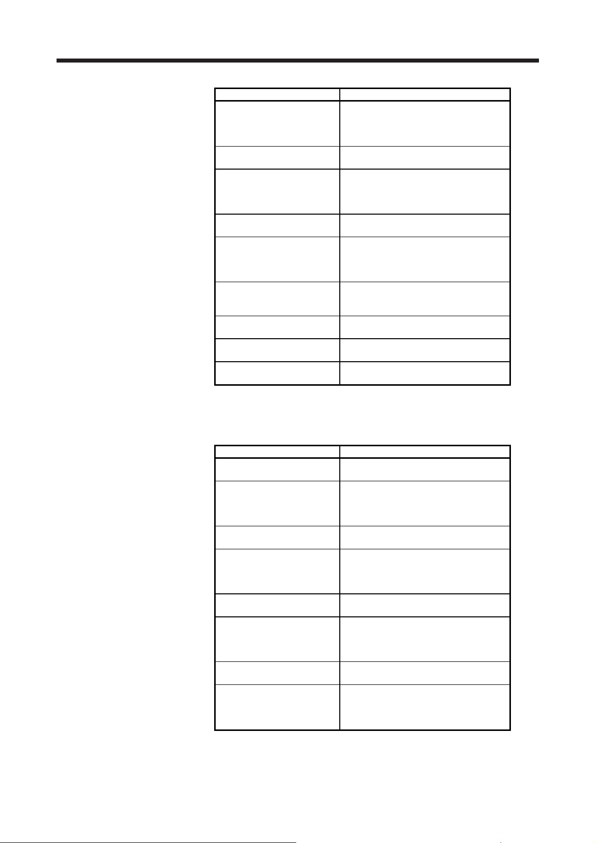
When you keep or use the equipment, please fulfill the following environment.
Item Environment
Ambient temperature
Storage -15 °C to 70 °C (non-freezing)
Ambient humidity
Storage 90 %RH or less (non-condensing)
Altitude Max. 1000 m above sea level
HG-SR51/HG-SR81/HG-SR52(4)/
Vibration resistance
(Note)
HG-SR121/HG-SR201/HG-SR202(4)/
HG-SR301/HG-SR421/HG-SR502(4)/
HG-JR45K1M4/HG-JR55K1M4/
Note. Except the geared servo motor.
Ambience
HG-MR Series/HG-KR Series/HG-AK Series X, Y: 49 m/s2
HG-SR102(4)/HG-SR152(4)/HG-JR53(4)/
HG-JR73(4)/HG-JR103(4)/HG-JR153(4)/
HG-JR203(4)/HG-JR353(4)/HG-JR503(4)/
HG-JR701M(4)/HG-JR11K1M(4)/
HG-JR15K1M(4)/HG-JR22K1M(4)/
HG-JR30K1M(4)/HG-JR37K1M(4)/
HG-JR601(4)/HG-JR801(4)/HG-JR12K1(4)/
HG-JR15K1(4)/HG-JR20K1(4)/HG-JR25K1(4)/
HG-RR Series/HG-UR72/HG-UR152
HG-SR352(4)/HG-UR202/HG-UR352/HG-UR502
HG-SR702(4)/HG-JR703(4)/HG-JR903(4)
HG-JR30K1(4)/HG-JR37K1(4)
Operation 0 °C to 40 °C (non-freezing)
Operation 80 %RH or less (non-condensing)
Indoors (no direct sunlight), free from corrosive
gas, flammable gas, oil mist, dust, and dirt
X, Y: 24.5 m/s
X: 24.5 m/s
X: 24.5 m/s
X: 9.8 m/s
2
2
Y: 49 m/s2
2
Y: 29.4 m/s2
2
Y: 9.8 m/s2
A - 3
r
(2) Wiring
CAUTION
Wire the equipment correctly and securely. Otherwise, the servo motor may operate unexpectedly.
Do not install a power capacitor, surge killer, or radio noise filter (FR-BIF-(H) option) on the servo
amplifier (converter unit) output side.
To avoid a malfunction, connect the wires to the correct phase terminals (U, V, and W) of the servo
amplifier (converter unit) and servo motor.
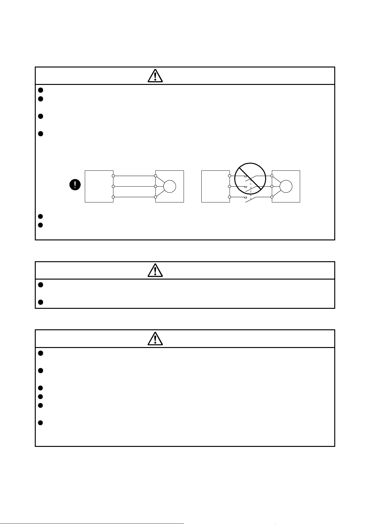
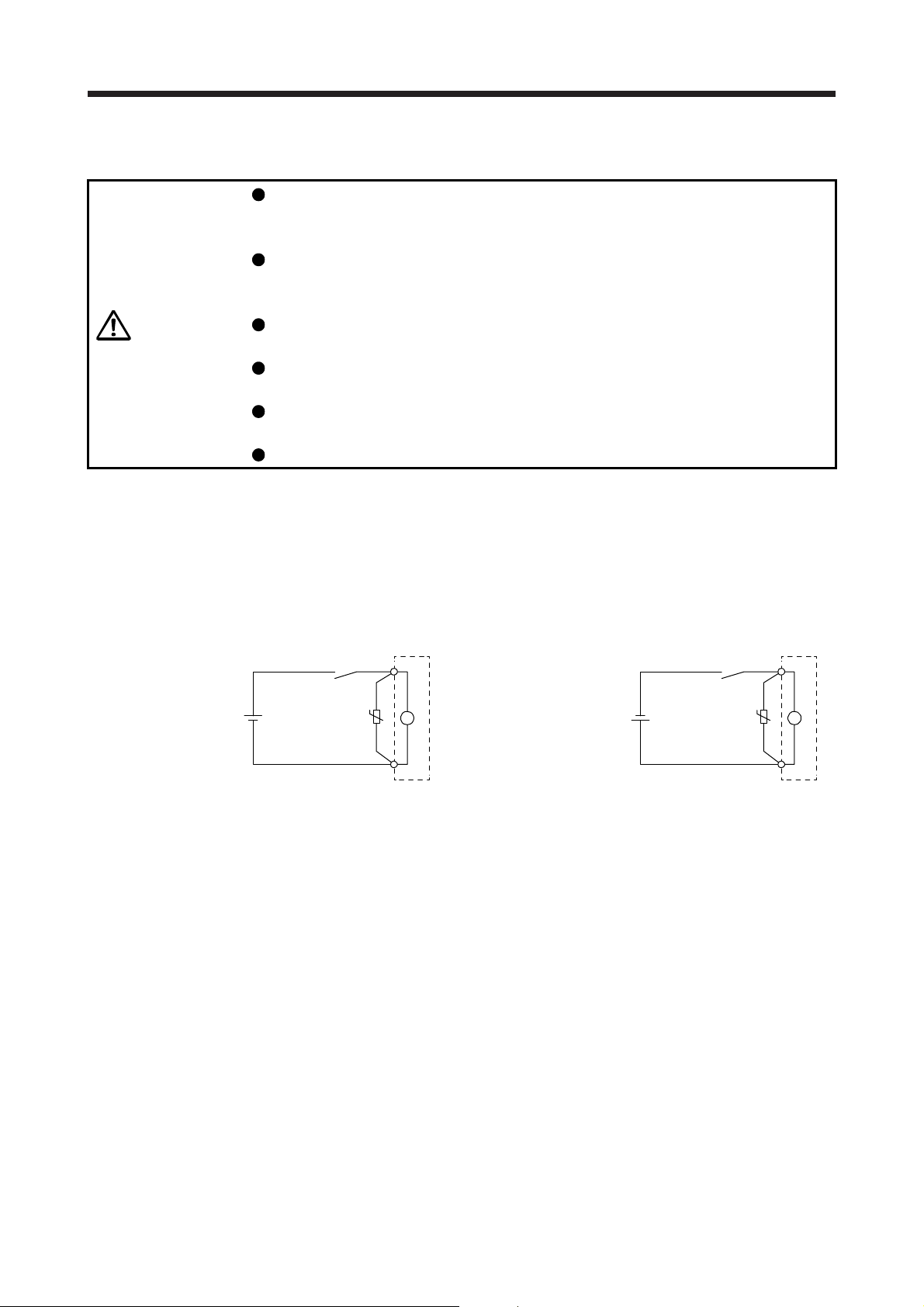
Connect the servo amplifier (converter unit) power output (U, V, and W) to the servo motor power input
(U, V, and W) directly. Do not let a magnetic contactor, etc. intervene. Otherwise, it may cause a
malfunction.
Servo amplifie
(converter unit)
U
V
W
Servo motor
U
V
W
M
Servo amplifier
(converter unit)
U
V
W
Servo motor
U
V
W
M
Do not connect AC power supply directly to the servo motor. Otherwise, it may cause a malfunction.
When the cable is not tightened enough to the terminal block, the cable or terminal block may generate
heat because of the poor contact. Be sure to tighten the cable with specified torque.
(3) Test run and adjustment
CAUTION
Before operation, check the parameter settings. Improper settings may cause some machines to operate
unexpectedly.
Never adjust or change the parameter values extremely as it will make operation unstable.
(4) Usage
CAUTION
Provide an external emergency stop circuit to ensure that operation can be stopped and power switched
off immediately.
Do not scratch the coated surface with hard objects nor clean the coated surface with an organic solvent.
Doing so may scuff the surface.
Do not disassemble, repair, or modify the equipment.
Use the servo amplifier (converter unit) with the specified servo motor.
The electromagnetic brake on the servo motor is designed to hold the motor shaft and should not be
used for ordinary braking.
For such reasons as service life and mechanical structure (e.g. where a ball screw and the servo motor
are coupled via a timing belt), the electromagnetic brake may not hold the motor shaft. To ensure safety,
install a stopper on the machine side.
A - 4
(5) Corrective actions
CAUTION
When it is assumed that a hazardous condition may occur due to a power failure or product malfunction,
use a servo motor with an electromagnetic brake or external brake to prevent the condition.
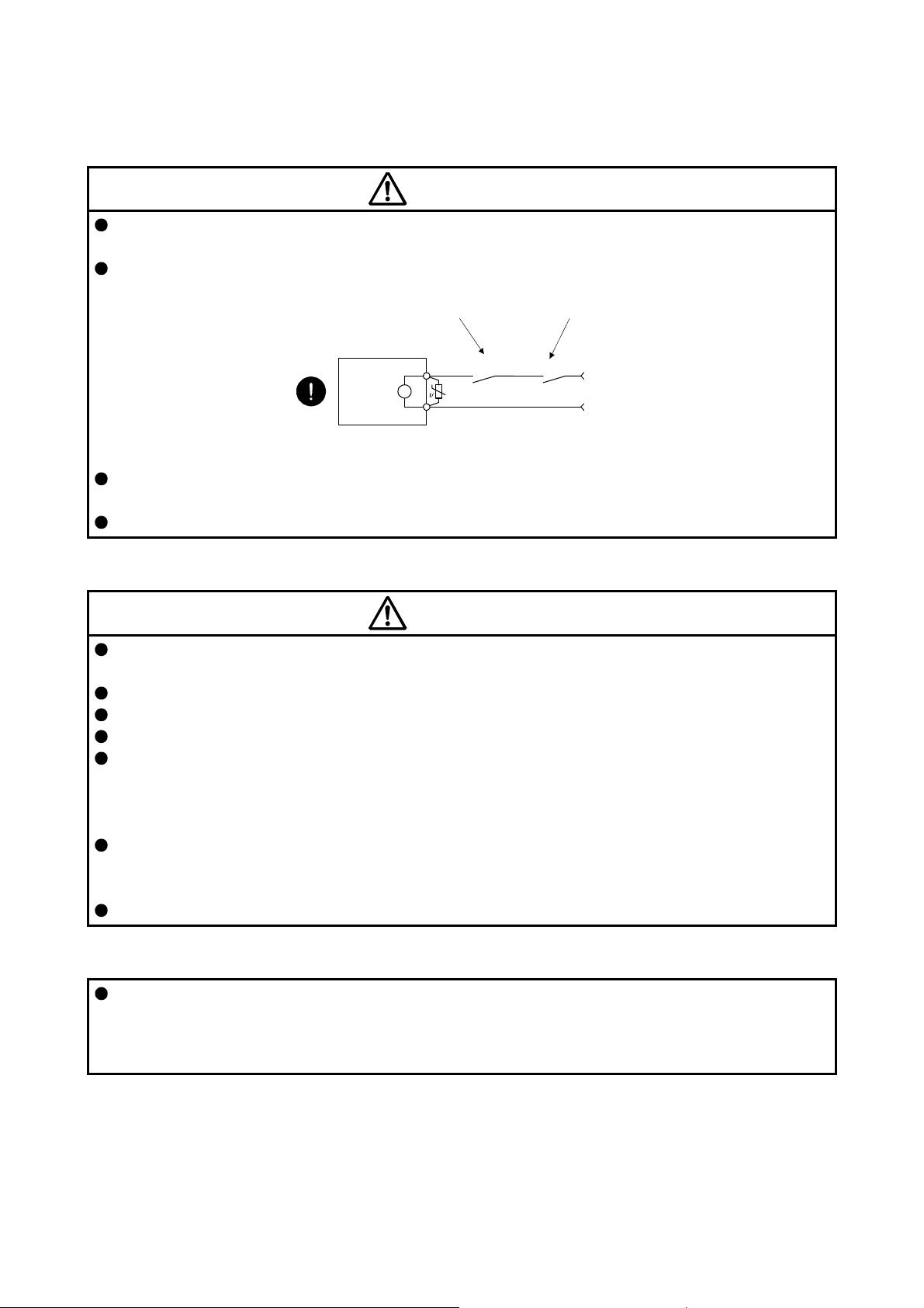
Configure an electromagnetic brake circuit so that it is activated also by an external EMG stop switch.
Contacts must be opened when ALM
(Malfunction) or MBR (Electromagnetic
brake interlock) turns off.
Contacts must be opened
with the EMG stop switch.
Servo motor
B
Electromagnetic brake
When any alarm has occurred, eliminate its cause, ensure safety, and deactivate the alarm before
restarting operation.
Provide an adequate protection to prevent unexpected restart after an instantaneous power failure.
RA
24 V DC
(6) Storage
CAUTION
Note the followings when storing the servo motor for an extended period of time (guideline: three or more
months).
Always store the servo motor indoors in a clean and dry place.
If it is stored in a dusty or damp place, make adequate provision, e.g. cover the whole product.
If the insulation resistance of the winding decreases, check how to store the equipment.
Though the servo motor is rust-proofed before shipment using paint or rust prevention oil, rust may be
produced depending on the storage conditions or storage period.
If the servo motor is to be stored for longer than six months, apply rust prevention oil again especially to
the machined surfaces of the shaft, etc.
Before using the product after storage for an extended period of time, hand-turn the servo motor output
shaft to confirm that nothing is wrong with the servo motor. When the servo motor is equipped with an
electromagnetic brake, check it after releasing the electromagnetic brake with the brake power supply.
When the product has been stored for an extended period of time, contact your local sales office.
(7) General instruction
To illustrate details, the equipment in the diagrams of this Instruction Manual may have been drawn
without covers and safety guards. When the equipment is operated, the covers and safety guards must
be installed as specified. Operation must be performed in accordance with this Specifications and
Instruction Manual.
A - 5
DISPOSAL OF WASTE
Please dispose a servo motor and other options according to your local laws and regulations.
«U.S. customary units»
U.S. customary units are not shown in this manual. Convert the values if necessary according to the
following table.
Mass 1 [kg] 2.2046 [lb]
Length 1 [mm] 0.03937 [inch]
Torque 1 [N•m] 141.6 [oz•inch]
Moment of inertia 1 [(× 10-4 kg•m2)] 5.4675 [oz•inch2]
Load (thrust load/axial load) 1 [N] 0.2248 [lbf]
Temperature N [°C] × 9/5 + 32 N [°F]
Quantity SI (metric) unit U.S. customary unit
A - 6
CONTENTS
1. INTRODUCTION 1- 1 to 1- 8
1.1 Rating plate ....................................................................................................................................... 1- 1
1.2 Parts identification ............................................................................................................................. 1- 2
1.3 Electromagnetic brake ...................................................................................................................... 1- 3
1.4 Servo motor shaft shapes ................................................................................................................. 1- 5
1.5 Servo motor with functional safety .................................................................................................... 1- 6
2. INSTALLATION 2- 1 to 2- 6
2.1 Mounting direction............................................................................................................................. 2- 2
2.2 Cooling fan ........................................................................................................................................ 2- 2
2.3 Load remove precautions ................................................................................................................. 2- 3
2.4 Permissible load for the shaft ........................................................................................................... 2- 4
2.5 Protection from oil and water ............................................................................................................ 2- 4
2.6 Cable ................................................................................................................................................. 2- 5
2.7 Servo motor with oil seal ................................................................................................................... 2- 5
2.8 Inspection items ................................................................................................................................ 2- 5
2.9 Parts having service lives ................................................................................................................. 2- 6
2.10 Machine accuracies ........................................................................................................................ 2- 6
3. CONNECTORS USED FOR SERVO MOTOR WIRING 3- 1 to 3-12
3.1 Selection of connectors .................................................................................................................... 3- 1
3.2 Wiring connectors (connector configurations A/B/C) ........................................................................ 3- 5
3.3 Wiring connectors (connector configurations D/E/F/G/H) ................................................................ 3- 6
3.4 Wiring connectors (connector configurations J/K/L/M/N/P/Q) ......................................................... 3-10
4. CONNECTION OF SERVO AMPLIFIER AND SERVO MOTOR 4- 1 to 4-26
4.1 Connection instructions .................................................................................................................... 4- 2
4.2 Wiring ................................................................................................................................................ 4- 3
4.2.1 HG-MR series/HG-KR series servo motor ................................................................................. 4- 3
4.2.2 HG-SR series/HG-JR series/HG-RR series/HG-UR series servo motor ................................... 4- 8
4.2.3 HG-AK series servo motor ........................................................................................................ 4-14
4.3 Selection example of wires .............................................................................................................. 4-16
4.4 Servo amplifier terminal section ....................................................................................................... 4-20
5. WIRING OPTION 5- 1 to 5-34
5.1 Cable/connector sets ........................................................................................................................ 5- 1
5.1.1 Combinations of cable/connector sets ....................................................................................... 5- 2
5.1.2 Cable and connector list ............................................................................................................. 5- 4
5.2 Encoder cable/connector sets ......................................................................................................... 5-10
5.3 Servo motor power cable ................................................................................................................. 5-27
5.4 Servo motor power cable (for HG-AK series) .................................................................................. 5-29
5.5 Electromagnetic brake cable ........................................................................................................... 5-30
5.6 Wires for option cables .................................................................................................................... 5-32
1
6. HG-MR SERIES/HG-KR SERIES 6- 1 to 6-58
6.1 Model code definition ........................................................................................................................ 6- 1
6.2 Combination list of servo motors and servo amplifiers ..................................................................... 6- 2
6.3 Standard specifications ..................................................................................................................... 6- 3
6.3.1 Standard specifications list......................................................................................................... 6- 3
6.3.2 Torque characteristics ................................................................................................................ 6- 5
6.4 Electromagnetic brake characteristics .............................................................................................. 6- 6
6.5 Servo motors with special shafts ...................................................................................................... 6- 7
6.5.1 Key shaft (with 2 round end key) ............................................................................................... 6- 7
6.5.2 D cut shaft .................................................................................................................................. 6- 7
6.6 Geared servo motors ........................................................................................................................ 6- 8
6.6.1 For general industrial machines (G1) ......................................................................................... 6- 8
6.6.2 For high precision applications (G5/G7) ................................................................................... 6-11
6.7 Mounting connectors ....................................................................................................................... 6-14
6.8 Dimensions ...................................................................................................................................... 6-15
6.8.1 Standard (without electromagnetic brake and reducer) ............................................................ 6-15
6.8.2 With an electromagnetic brake ................................................................................................. 6-18
6.8.3 For general industrial machine with a reducer (without an electromagnetic brake) ................. 6-21
6.8.4 For general industrial machine with a reducer (with an electromagnetic brake) ...................... 6-28
6.8.5 With flange-output type reducer for high precision applications, flange mounting (without an
electromagnetic brake) .............................................................................................................. 6-34
6.8.6 With flange-output type reducer for high precision applications, flange mounting (with an
electromagnetic brake) .............................................................................................................. 6-40
6.8.7 With shaft-output type reducer for high precision applications, flange mounting (without an
electromagnetic brake) .............................................................................................................. 6-46
6.8.8 With shaft-output type reducer for high precision applications, flange mounting (with an
electromagnetic brake) .............................................................................................................. 6-52
7. HG-SR SERIES 7- 1 to 7-96
7.1 Model code definition ........................................................................................................................ 7- 1
7.2 Combination list of servo motors and servo amplifiers ..................................................................... 7- 2
7.3 Standard specifications ..................................................................................................................... 7- 3
7.3.1 Standard specifications list......................................................................................................... 7- 3
7.3.2 Torque characteristics ................................................................................................................ 7- 6
7.4 Electromagnetic brake characteristics .............................................................................................. 7- 8
7.5 Servo motors with special shafts ...................................................................................................... 7- 9
7.6 Geared servo motors ....................................................................................................................... 7-10
7.6.1 For general industrial machines (G1/G1H) ............................................................................... 7-10
7.6.2 For high precision applications (G5/G7) ................................................................................... 7-14
7.7 Dimensions ...................................................................................................................................... 7-17
7.7.1 Standard (without electromagnetic brake and reducer) ............................................................ 7-17
7.7.2 With an electromagnetic brake ................................................................................................. 7-20
7.7.3 For general industrial machine with a reducer (without an electromagnetic brake) ................. 7-27
7.7.4 For general industrial machine with a reducer (with an electromagnetic brake) ...................... 7-37
7.7.5 For general industrial machine with a reducer (foot-mounting/without an
electromagnetic brake) ............................................................................................................ 7-47
7.7.6 For general industrial machine with a reducer (foot-mounting/with an
electromagnetic brake) .............................................................................................................. 7-57
2
7.7.7 With flange-output type reducer for high precision applications, flange mounting (without an
electromagnetic brake) .............................................................................................................. 7-68
7.7.8 With flange-output type reducer for high precision applications, flange mounting (with an
electromagnetic brake) .............................................................................................................. 7-75
7.7.9 With shaft-output type reducer for high precision applications, flange mounting (without an
electromagnetic brake) .............................................................................................................. 7-82
7.7.10 With shaft-output type reducer for high precision applications, flange mounting (with an
electromagnetic brake) ........................................................................................................... 7-89
8. HG-JR SERIES 8- 1 to 8-46
8.1 Model designation ............................................................................................................................. 8- 1
8.2 Combination list of servo motors and servo amplifiers/drive units ................................................... 8- 2
8.3 Standard specifications ..................................................................................................................... 8- 8
8.3.1 Standard specifications list......................................................................................................... 8- 8
8.3.2 Torque characteristics ............................................................................................................... 8-15
8.4 Electromagnetic brake characteristics ............................................................................................. 8-19
8.5 Servo motors with special shafts ..................................................................................................... 8-20
8.6 Oil seal ............................................................................................................................................. 8-21
8.7 Cooling fan ....................................................................................................................................... 8-21
8.8 Dimensions ...................................................................................................................................... 8-22
8.8.1 Terminal box detail diagram ...................................................................................................... 8-22
8.8.2 Standard (without an electromagnetic brake) ........................................................................... 8-23
8.8.3 With an electromagnetic brake ................................................................................................. 8-37
9. HG-RR SERIES 9- 1 to 9-12
9.1 Model designation ............................................................................................................................. 9- 1
9.2 Combination list of servo motors and servo amplifiers ..................................................................... 9- 1
9.3 Standard specifications ..................................................................................................................... 9- 2
9.3.1 Standard specifications list......................................................................................................... 9- 2
9.3.2 Torque characteristics ................................................................................................................ 9- 4
9.4 Electromagnetic brake characteristics .............................................................................................. 9- 5
9.5 Servo motors with special shafts ...................................................................................................... 9- 6
9.6 Oil seal .............................................................................................................................................. 9- 6
9.7 Dimensions ....................................................................................................................................... 9- 7
9.7.1 Standard (without an electromagnetic brake) ............................................................................ 9- 7
9.7.2 With an electromagnetic brake .................................................................................................. 9- 9
10. HG-UR SERIES 10- 1 to 10-12
10.1 Model designation .......................................................................................................................... 10- 1
10.2 Combination list of servo motors and servo amplifiers .................................................................. 10- 1
10.3 Standard specifications .................................................................................................................. 10- 2
10.3.1 Standard specifications list ...................................................................................................... 10- 2
10.3.2 Torque characteristics ............................................................................................................. 10- 4
10.4 Electromagnetic brake characteristics ........................................................................................... 10- 5
10.5 Servo motors with special shafts ................................................................................................... 10- 6
10.6 Oil seal ........................................................................................................................................... 10- 6
10.7 Dimensions .................................................................................................................................... 10- 7
10.7.1 Standard (without an electromagnetic brake) ......................................................................... 10- 7
3
10.7.2 With an electromagnetic brake ................................................................................................ 10- 9
11. HG-AK SERIES 11- 1 to 11-14
11.1 Model designation .......................................................................................................................... 11- 1
11.2 Combination list of servo motors and servo amplifiers .................................................................. 11- 1
11.3 Standard specifications .................................................................................................................. 11- 2
11.3.1 Standard specifications list ...................................................................................................... 11- 2
11.3.2 Torque characteristics ............................................................................................................. 11- 4
11.4 Electromagnetic brake characteristics ........................................................................................... 11- 5
11.5 Servo motors with special shafts ................................................................................................... 11- 6
11.6 Dimensions .................................................................................................................................... 11- 7
11.6.1 Standard (without an electromagnetic brake) ......................................................................... 11- 8
11.6.2 With an electromagnetic brake ............................................................................................... 11-11
APPENDIX App. - 1 to App. -35
App. 1 Servo motor ID codes .......................................................................................................... App.- 1
App. 2 Manufacturer list .................................................................................................................. App.- 3
App. 3 Compliance with the CE marking ......................................................................................... App.- 4
App. 4 Compliance with UL/CSA standard ..................................................................................... App.- 5
App. 5 Calculation methods for designing ....................................................................................... App.- 9
App. 6 Selection example of servo motor power cable .................................................................. App.-27
App. 7 Crimping connector for CNP3_ ........................................................................................... App.-28
App. 8 Connector dimensions ........................................................................................................ App.-29
App. 9 HG-JR22K1M(4) appearance change ................................................................................ App.-35
4
1. INTRODUCTION
1. INTRODUCTION
1.1 Rating plate
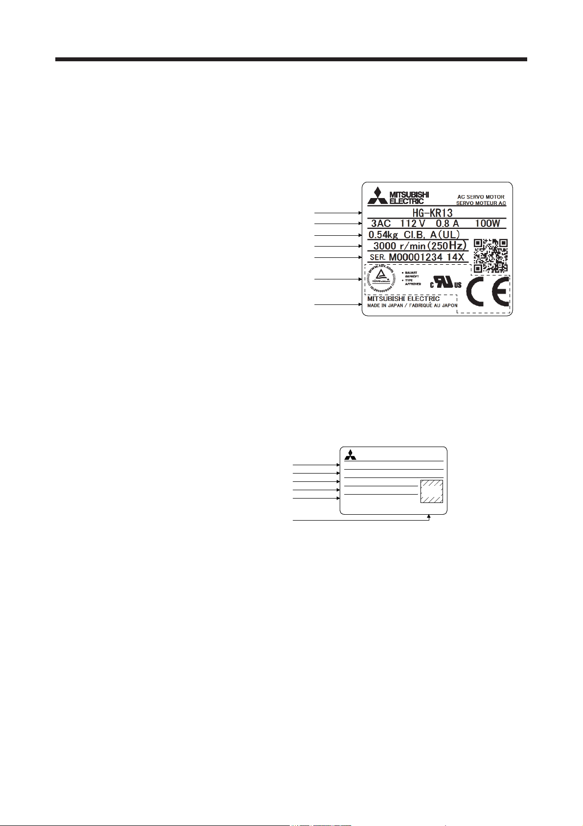
The following shows an example of rating plate for explanation of each item.
(1) HG-MR/HG-KR/HG-SR/HG-JR/HG-RR/HG-UR series servo motor
Model
Input power and rated output
Mass and insulation class
Rated speed
Serial number (Note 1)
(Note 2)
Country of origin
(2) HG-AK series servo motor
Note 1. Production year and month of the servo motor are indicated in a serial number on
the rating plate.
The year and month are indicated by the last two digits of the year and one digit
of the month [1 to 9, X(10), Y(11), and Z(12)].
For January 2012, the Serial No. is like, "SER. _ _ _ _ _ _ _ _ _ 121".
2. Products approved by Certification Bodies are marked. The marks depends on
the Certification Bodies.
AC SERVO MOTORMITSUBISHI
Model, Insulation class
Input power, Mass
Rated output, IP rating
Rated speed
Serial number (Note)
Country of origin
Note. Production year and month of the servo motor are indicated in a serial number on the
rating plate.
The year and month of manufacture are indicated by the last two digits of the year
and one digit of the month [1 to 9, X (10), Y (11), and Z (12)].
For June 2012, the Serial No. is like, "SER. _ _ _ _ _ _ _ _ _ 126".
HG-AK0336
INPUT 3AC 13V 2.2A 0.16kg
OUTPUT 30W IP55
3000 r/min (200Hz)
SER. J12345678 125
CI.B
QR
code
MADE IN JAPANMITSUBISHI ELECTRIC
1 - 1
1. INTRODUCTION
A
)
r
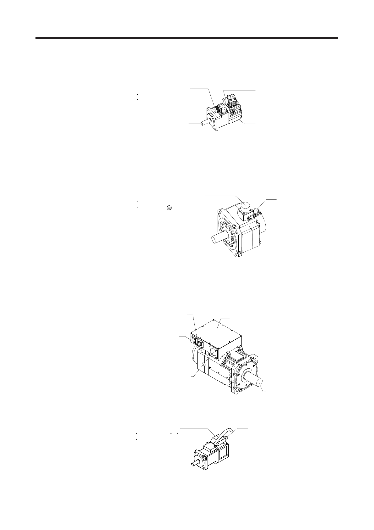
1.2 Parts identification
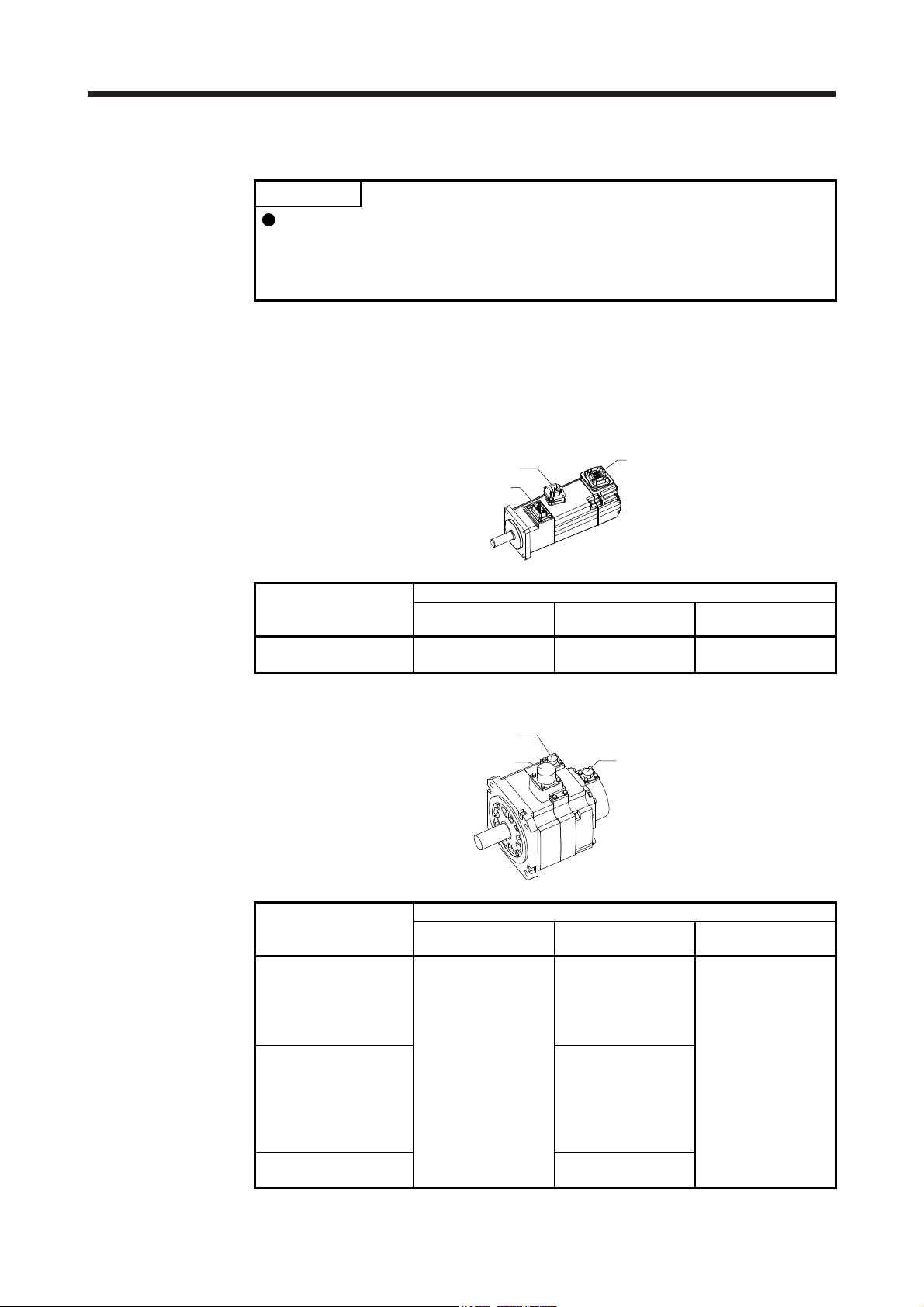
(1) HG-MR series/HG-KR series servo motor
Power cable (Note 1, 2)
Power lead (U/V/W)
Grounding lead
Encoder cable (Note 1)
Servo motor shaft
Note 1. The encoder cable and power supply cable are options.
2.
n electromagnetic brake cable is separately required for the servo motor with an
electromagnetic brake.
Encoder
(2) HG-SR series/HG-JR53(4) to HG-JR903(4)/HG-JR701M(4) to HG-JR15K1M(4)/HG-JR601(4) to HG-
JR12K1(4)/HG-RR series/HG-UR series servo motor
Power supply connector (Note
Power supply (U/V/W)
Grounding ( )
Servo motor shaft
Note. The servo motor with an electromagnetic brake has the electromagnetic brake
connector separately.
Encoder connector
Encoder
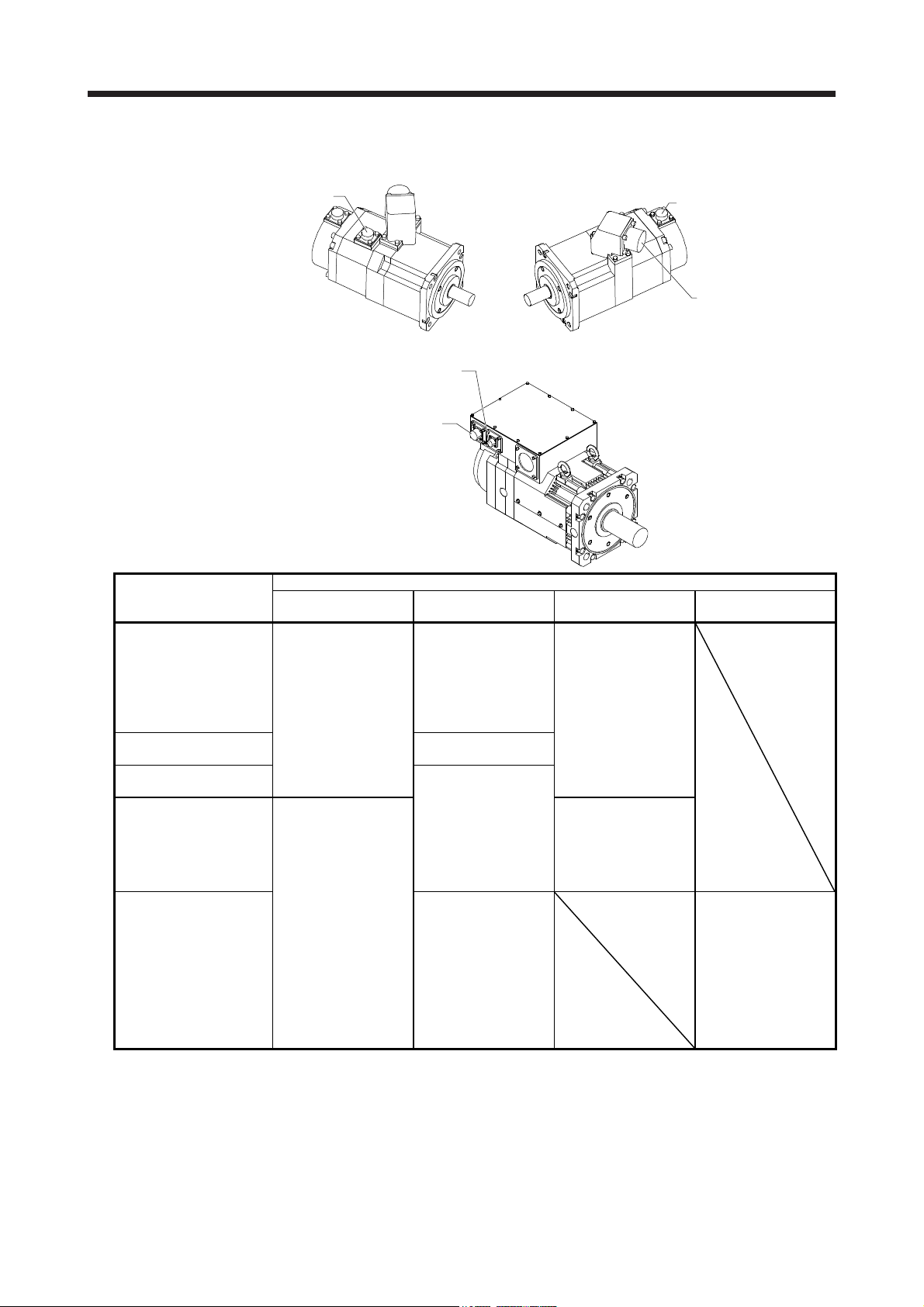
(3) HG-JR22K1M(4) to HG-JR37K1M(4)/HG-JR45K1M4/HG-JR55K1M4/HG-JR15K1(4) to HG-JR37K1(4)
servo motor
Cooling fan connecto
Terminal box
(4) HG-AK series servo motor
Encoder connector
Power lead hole
Servo motor shaft
Power cable (Note)
Power lead (U V W)
Earth lead
Servo motor shaft
Note. The servo motor with an electromagnetic brake has electromagnetic brake lead.
Encoder cable
Encoder
1 - 2
1. INTRODUCTION
1.3 Electromagnetic brake
The electromagnetic brake is provided to prevent a drop at a power failure or
servo alarm occurrence during vertical drive or to hold a shaft at a stop. Do not
use it for normal braking (including braking at servo-lock).
The electromagnetic brake has a time lag. Use the electromagnetic brake so that
servo motor control starts after the electromagnetic brake has completely opened.
Be sure to check the time lag of the braking with a real machine.
Configure an electromagnetic brake circuit so that it is activated also by an
CAUTION
The servo motor with an electromagnetic brake can be used to prevent a drop in vertical lift applications or to
ensure double safety at an emergency stop, for example. When operating the servo motor, supply power to
the electromagnetic brake to release the brake. Switching power off enables the electromagnetic brake.
(1) Electromagnetic brake power supply
Prepare the following power supply for use with the electromagnetic brake only. The electromagnetic
brake terminals (B1 and B2) have no polarity.
external EMG stop switch.
For details of the circuit configuration and timing chart, refer to each servo
amplifier instruction manual.
While the electromagnetic brake is opened, the motor may be raised to high
temperature regardless of driving.
The life will be shorten under sudden acceleration/deceleration conditions.
B1
B1
24 V DC
power supply for
electromagnetic brake
Switch
VAR
B
U
B2
Electromagnetic brake
24 V DC
or
power supply for
electromagnetic brake
Switch
VAR
The surge absorber (VAR) must be installed between B1 and B2. For the selection and example of
surge absorbers, refer to "Electromagnetic brake characteristic" in the chapter of servo motor series.
When you use a diode for a surge absorber, the electromagnetic braking time will be longer.
B
U
B2
Electromagnetic brake
1 - 3
1. INTRODUCTION
(2) Sound generation
Though the brake lining may rattle during operation, it poses no functional problem.
If braking sounds, it may be improved by setting the machine resonance suppression filter in the servo
amplifier (converter unit) parameters. For details, refer to each servo amplifier instruction manual.
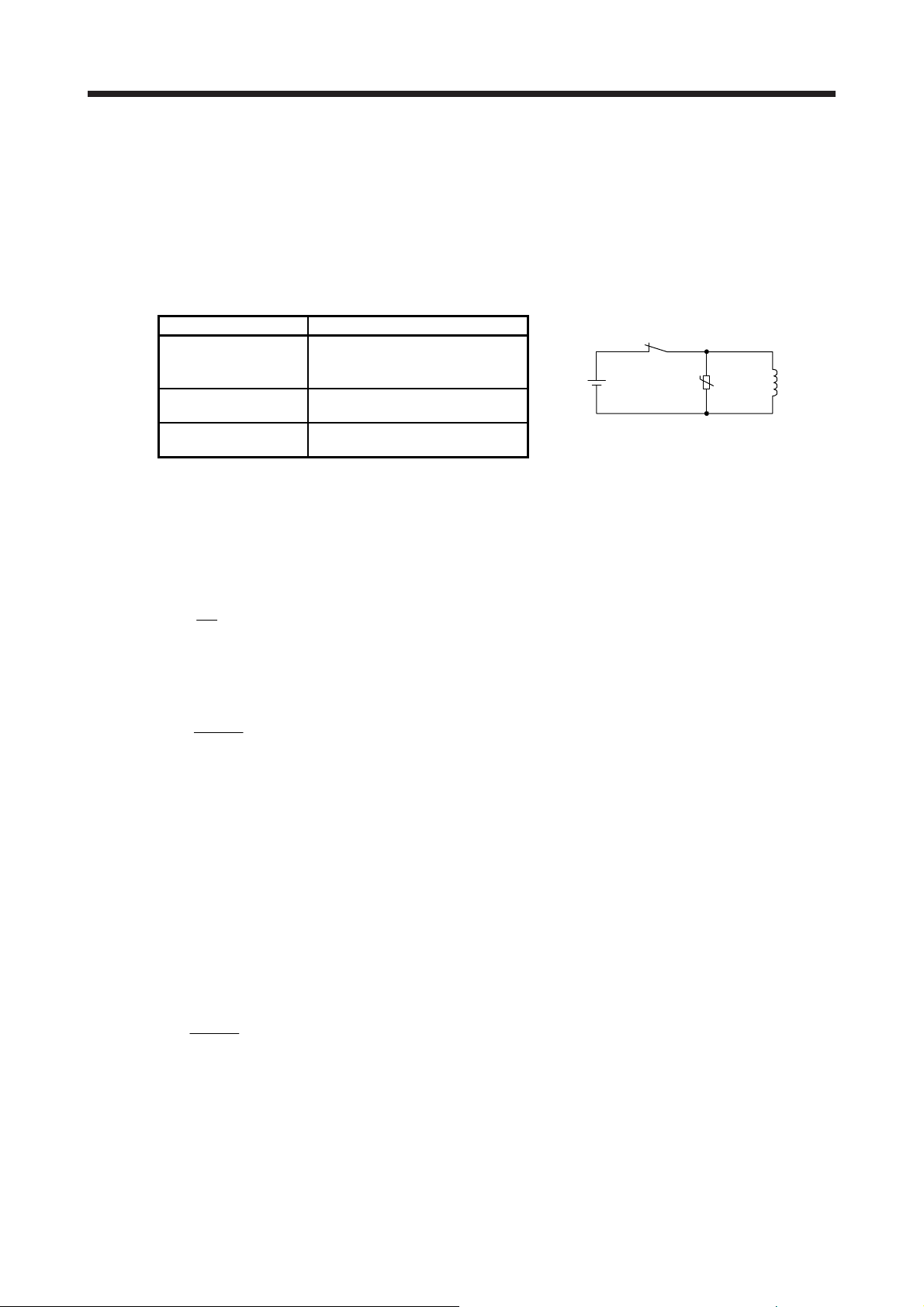
(3) Selection of surge absorbers for electromagnetic brake circuit
The following shows an example how to select a varistor with a surge absorber.
(a) Selection conditions
Electromagnetic brake
specification
Desired suppression
voltage
Durable surge
application time
(b) Tentative selection and verification of surge absorber
1) Maximum allowable circuit voltage of varistor
Tentatively select a varistor whose maximum allowable voltage is larger than Vb [V].
2) Brake current (Ib)
Ib =
3) Energy (E) generated by brake coil
E =
4) Varistor limit voltage (Vi)
From the energy (E) generated in the brake coil and the varister characteristic diagram, calculate
the varistor limit voltage (Vi) when the brake current (Ib) flows into the tentatively selected varistor
during opening of the circuit.
Vi is favorable when the varistor limit voltage (Vi) [V] is smaller than the desired suppressed
voltage (Vs) [V].
If Vi is not smaller than Vs, reselect a varistor or improve the withstand voltage of devices.
5) Surge current width (τ)
Given that the varistor absorbs all energies, the surge current width (τ) will be as follows.
τ =
6) Examining surge life of varister
From the varistor characteristic diagram, the guaranteed current value (Ip) in which the number of
the surge application life is N at the surge current width (τ). Calculate the guaranteed current
value (Ip) ratio to brake current (Ib).
If an enough margin is ensured for Ip/Ib, the number of the surge application life N [time] can be
considered as favorable.
Item Condition
R [Ω]: Resistance
L [H]: Inductance
Vb [V]: Power supply voltage
Vs [V] or less
N times
Vb
[A]
R
2
L × lb
[J]
2
E
Vi × lb
[S]
Relay
24 V DC
U
Varistor
Brake coil
1 - 4
1. INTRODUCTION
(4) Others
A leakage magnetic flux will occur at the shaft end of the servo motor equipped with an electromagnetic
brake. Note that chips, screws, etc. are attracted.
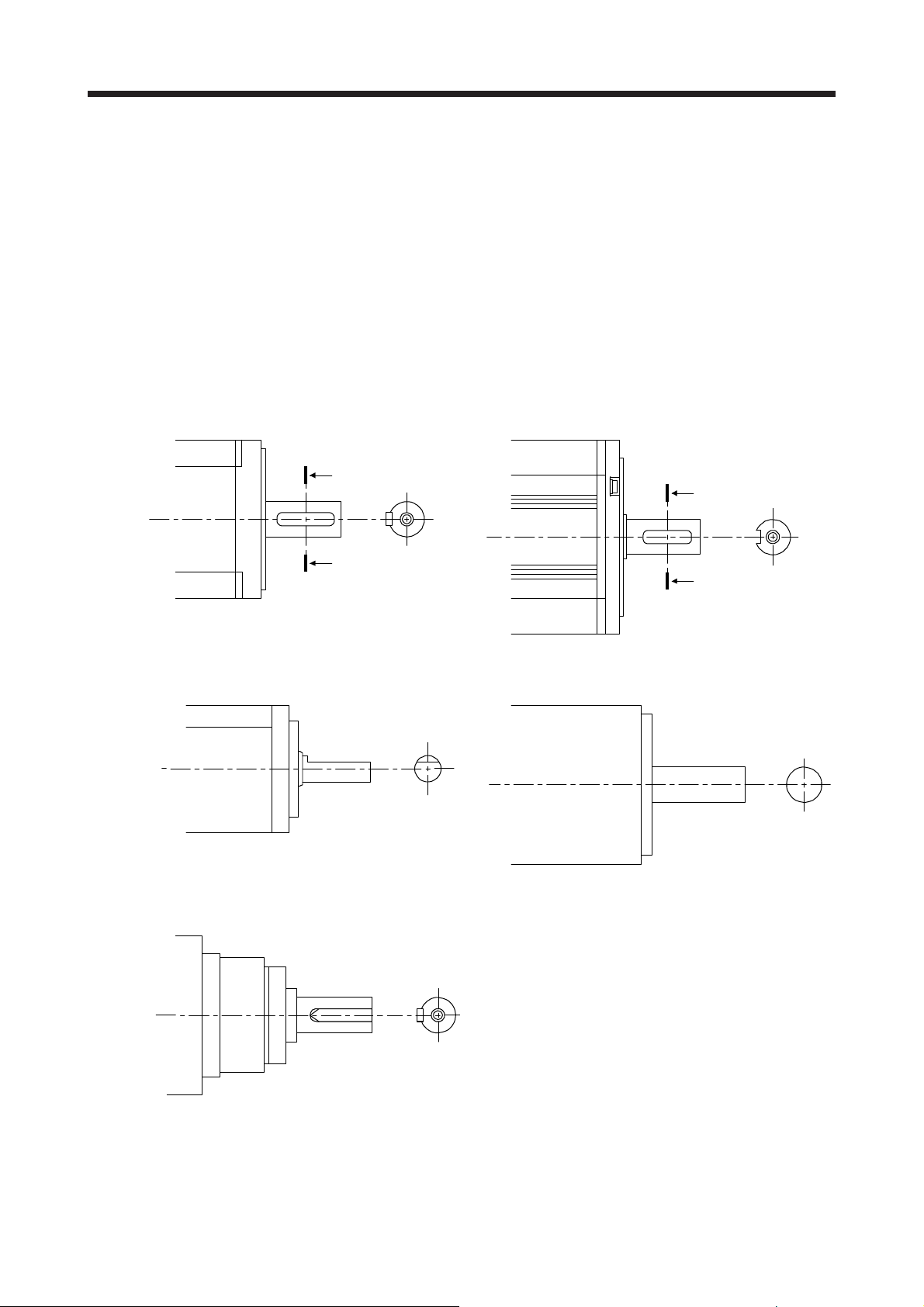
1.4 Servo motor shaft shapes
In addition to the straight shaft, the key shaft and D cut shaft are available.
The key shaft and D cut shaft cannot be used in frequent start/stop applications.
Since we cannot warrant the servo motor against fracture and similar accidents attributable to a loose key,
use a friction coupling, etc. when coupling the shaft with a machine.
The shaft shape of the standard servo motor changes depending on the series and capacity. Refer to the
chapter of the servo motor series.
The key shaft (with single pointed key) applies to only the geared servo motor for high precision application.
A
A
A
Shaft section view AA
A
Shaft section view AA
Key shaft (with 2 round end key) Key shaft (without key)
D cut shaft Straight shaft
Key shaft (with single pointed key)
1 - 5
1. INTRODUCTION
1.5 Servo motor with functional safety
POINT
When you use a servo motor with functional safety, MR-BT6VCASE battery
case cannot be used.
HG-KR, HG-SR, and HG-JR series provide a special specification which expands the safety observation
function with the use of MR-D30 functional safety units and MR-J4-_-RJ servo amplifiers. When using the
servo motor with functional safety, be sure to attach MR-D30 functional safety unit to the servo amplifier.
Other servo motors than HG-KR, HG-SR, and HG-JR series are not compatible with the functional safety.
The servo motors with functional safety have the same specifications and dimensions with the standard
servo motors.
The following is a list of servo amplifiers which are compatible with the servo motors with functional safety.
Refer to section 4.1 of "MR-D30 Instruction Manual" (SH030132) for the available safety observation
functions and achievable safety level.
(1) A combination with 200 V/100 V class servo amplifiers
Servo motor with functional safety Servo amplifier
HG-KR053W0C
HG-KR13W0C
HG-KR23W0C MR-J4-20B-RJ
HG-KR43W0C MR-J4-40B-RJ
HG-SR51W0C
HG-SR52W0C
HG-JR53W0C MR-J4-60B-RJ
HG-KR73W0C MR-J4-70B-RJ
HG-JR73W0C MR-J4-70B-RJ
HG-SR81W0C
HG-SR102W0C
HG-JR103W0C MR-J4-100B-RJ
HG-SR121W0C
HG-SR201W0C
HG-SR152W0C
HG-SR202W0C
MR-J4-10B-RJ
MR-J4-10A-RJ
MR-J4-10B1-RJ
MR-J4-10A1-RJ
MR-J4-20A-RJ
MR-J4-20B1-RJ
MR-J4-20A1-RJ
MR-J4-40A-RJ
MR-J4-40B1-RJ
MR-J4-40A1-RJ
MR-J4-60B-RJ
MR-J4-60A-RJ
MR-J4-60A-RJ
MR-J4-100B-RJ (Note)
MR-J4-100A-RJ (Note)
MR-J4-70A-RJ
MR-J4-70A-RJ
MR-J4-200B-RJ (Note)
MR-J4-200A-RJ (Note)
MR-J4-100B-RJ
MR-J4-100A-RJ
MR-J4-100A-RJ
MR-J4-200B-RJ (Note)
MR-J4-200A-RJ (Note)
MR-J4-200B-RJ
MR-J4-200A-RJ
1 - 6
1. INTRODUCTION
Servo motor with functional safety Servo amplifier
HG-JR153W0C
HG-JR203W0C
HG-SR301W0C
HG-SR352W0C
HG-JR353W0C MR-J4-350B-RJ
HG-SR421W0C
HG-SR502W0C
HG-JR503W0C MR-J4-500B-RJ
HG-SR702W0C
HG-JR703W0C
HG-JR701MW0C
HG-JR903W0C
HG-JR11K1MW0C
HG-JR15K1MW0C MR-J4-15KB-RJ
HG-JR22K1MW0C MR-J4-22KB-RJ
(2) A combination with 400 V class servo amplifiers
Note. This combination increases the maximum torque from 300% to 400% of the rated
torque.
Servo motor with functional safety Servo amplifier
HG-SR524W0C MR-J4-60B4-RJ
HG-JR534W0C MR-J4-60B4-RJ
HG-SR1024W0C
HG-JR1034W0C
HG-JR734W0C
HG-JR1034W0C
HG-SR1524W0C
HG-SR2024W0C
HG-JR1534W0C
HG-JR2034W0C
HG-SR3524W0C MR-J4-350B4-RJ
HG-JR3534W0C MR-J4-350B4-RJ
MR-J4-200B-RJ
MR-J4-200A-RJ
MR-J4-350B-RJ (Note)
MR-J4-350A-RJ (Note)
MR-J4-350B-RJ
MR-J4-350A-RJ
MR-J4-350A-RJ
MR-J4-500B-RJ (Note)
MR-J4-500A-RJ (Note)
MR-J4-500B-RJ
MR-J4-500A-RJ
MR-J4-500A-RJ
MR-J4-700B-RJ (Note)
MR-J4-700A-RJ (Note)
MR-J4-700B-RJ
MR-J4-700A-RJ
MR-J4-11KB-RJ
MR-J4-11KA-RJ
MR-J4-15KA-RJ
MR-J4-22KA-RJ
MR-J4-60A4-RJ
MR-J4-60A4-RJ
MR-J4-100B4-RJ (Note 1)
MR-J4-100A4-RJ (Note 1)
MR-J4-100B4-RJ
MR-J4-100A4-RJ
MR-J4-100B4-RJ
MR-J4-100A4-RJ
MR-J4-200B4-RJ (Note 1)
MR-J4-200A4-RJ (Note 1)
MR-J4-200B4-RJ
MR-J4-200A4-RJ
MR-J4-200B4-RJ
MR-J4-200A4-RJ
MR-J4-350B4-RJ (Note 1)
MR-J4-350A4-RJ (Note 1)
MR-J4-350A4-RJ
MR-J4-350A4-RJ
MR-J4-500B4-RJ (Note 1)
MR-J4-500A4-RJ (Note 1)
1 - 7
1. INTRODUCTION
Servo motor with functional safety Servo amplifier
HG-SR5024W0C MR-J4-500B4-RJ
MR-J4-500A4-RJ
HG-JR5034W0C MR-J4-500B4-RJ
MR-J4-500A4-RJ
MR-J4-700B4-RJ (Note)
MR-J4-700A4-RJ (Note)
HG-SR7024W0C
HG-JR7034W0C
HG-JR701M4W0C
HG-JR9034W0C
HG-JR11K1M4W0C
HG-JR15K1M4W0C MR-J4-15KB4-RJ
HG-JR22K1M4W0C MR-J4-22KB4-RJ
Note. This combination increases the maximum torque from 300% to 400% of the rated
torque.
MR-J4-700B4-RJ
MR-J4-700A4-RJ
MR-J4-11KB4-RJ
MR-J4-11KA4-RJ
MR-J4-15KA4-RJ
MR-J4-22KA4-RJ
1 - 8
2. INSTALLATION
2. INSTALLATION
WARNING
CAUTION
To prevent electric shock, ground each equipment securely.
Stacking in excess of the specified number of product packages is not allowed.
Install the equipment on incombustible material. Installing it directly or close to
combustibles will lead to a fire.
Install the servo motor in a load-bearing place in accordance with the Instruction
Manual.
Do not get on or put heavy load on the equipment. Otherwise, it may cause injury.
Use the equipment within the specified environmental range. For the
environment, refer to the specifications of the servo motor series.
Do not drop or strike the servo motor. Isolate it from all impact loads.
Do not install or operate a faulty servo motor.
Do not carry the servo motor by holding the cables, shaft, encoder, or connector.
Otherwise, it may cause a malfunction or injury.
Use the eyebolts of the servo motor to only transport it. Do not use the eyebolts to
transport the servo motor when it is mounted on a machine.
The geared servo motor must be mounted in the specified direction. Otherwise, it
can leak oil, leading to a fire or malfunction.
Securely fix the servo motor to the machine. If being attached insecurely, the
servo motor may come off during operation, leading to injury.
Be sure to measure the motor vibration level with the servo motor mounted on the
machine when checking the vibration level. A great vibration may cause the early
damage of a bearing, encoder, brake, and reducer. The great vibration may also
cause the poor connector connection or bolt looseness.
For the gain adjustment at the equipment startup, check the torque waveform and
the speed waveform with a measurement device to check that no vibration
occurs. If the vibration occurs due to high gain, the vibration may cause the early
damage of the servo motor.
Never hit the servo motor or shaft, especially when coupling the servo motor to
the machine. Otherwise, the encoder may malfunction.
When coupling a load to the servo motor, do not use a rigid coupling. Doing so
can cause the shaft to break and the bearing to wear out.
Balance the load to the extent possible. Not doing so can cause vibration during
servo motor operation or damage the bearings and encoder.
Take safety measures, e.g. provide covers, to prevent accidental access to the
rotor of the servo motor during operation.
Do not subject the servo motor shaft to more than the permissible load.
Otherwise, the shaft may break, leading to injury.
When the product has been stored for an extended period of time, contact your
local sales office.
When handling the servo motor, be careful about the edged parts such as the
corners of the servo motor.
2 - 1
2. INSTALLATION
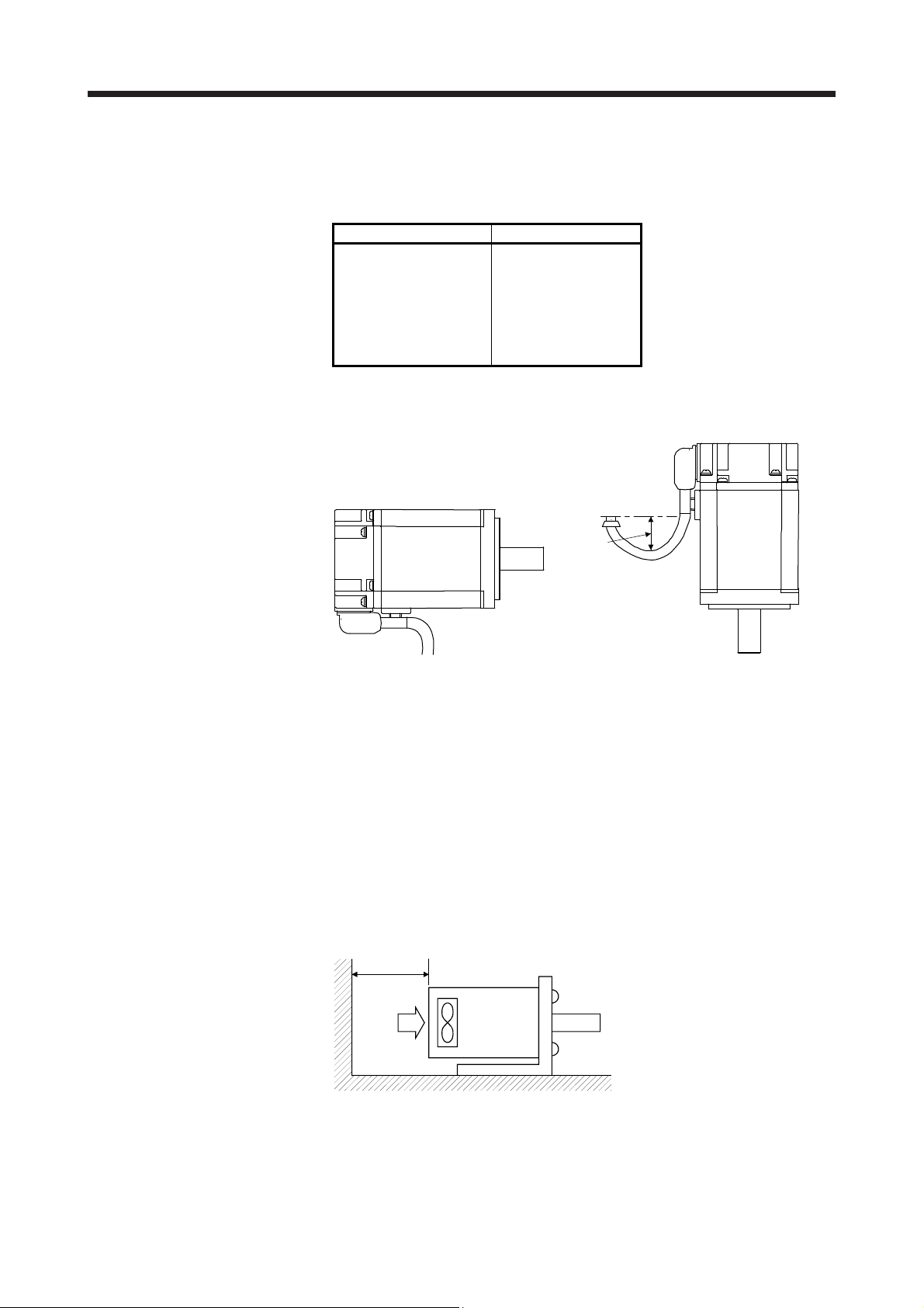
2.1 Mounting direction
(1) Standard servo motor
The following table indicates the mounting direction of the standard servo motor.
For mounting in the horizontal direction, it is recommended to set the connector section downward.
When mounting the motor vertically or obliquely, give a little slack for the connection cable.
Servo motor series Mounting direction
HG-MR
HG-KR
HG-SR
HG-JR
HG-RR
HG-UR
HG-AK
All directions
Little slack
(2) Servo motor with an electromagnetic brake
The servo motor with an electromagnetic brake can also be installed in the same orientation as the
standard servo motor. When the servo motor with an electromagnetic brake is installed with the shaft
end at top, the brake plate may generate sliding sound but it is not a fault.
(3) Geared servo motors
The mounting direction of the geared servo motor differs depending on the reducer type. Be sure to
mount it in the specified direction. Refer to the chapter of the servo motor series for details.
2.2 Cooling fan
For the servo motor with a cooling fan, ensure to put enough space for the distance L between intake port
and wall surface. Refer to the chapter of the servo motor series for the distance L.
L or more
Servo motor
Intake
Cooling fan
2 - 2
2. INSTALLATION
2.3 Load remove precautions
During assembling, the shaft end must not be hammered. Otherwise, the encoder
may malfunction.
CAUTION
Do not process the shaft to avoid damage to the encoder and bearing.
(1) When mounting a pulley to the servo motor with a key shaft, use the screw hole in the shaft end. To fit
the pulley, first insert a double-end stud into the screw hole of the shaft, put a washer against the end
face of the coupling, and insert and tighten a nut to force the pulley in.
Servo motor
Double-end stud
Nut
Pulley
Washer
(2) For the shaft without a key, use a friction coupling or the like.
(3) When removing the pulley, use a pulley remover to protect the shaft from hard load and or impact.
(4) To ensure safety, fit a protective cover or the like on the rotary area, such as the pulley, mounted to the
shaft.
(5) When a threaded shaft end part is needed to mount a pulley on the shaft, please contact your local sales
office.
(6) The direction of the encoder on the servo motor cannot be changed.
(7) When mounting the servo motor, use spring washers, etc. and fully tighten the bolts so that they do not
become loose due to vibration.
2 - 3
2. INSTALLATION
2.4 Permissible load for the shaft
CAUTION
For the permissible shaft load specific to the servo motor, refer to the chapter of the servo motor series.
(1) Use a flexible coupling and adjust the misalignment of the shaft to less than the permissible radial load.
(2) When using a pulley, sprocket or timing belt, select a diameter that will fit into the permissible radial load.
(3) Excess of the permissible load can cause the bearing life to reduce and the shaft to break.
(4) The load indicated in this section is static load in a single direction and does not include eccentric load.
Make eccentric load as small as possible. Not doing so can cause the servo motor to be damaged.
2.5 Protection from oil and water
Do not use a rigid coupling as it may apply excessive bending load to the shaft of
the servo motor, leading the shaft to break and the bearing to wear out.
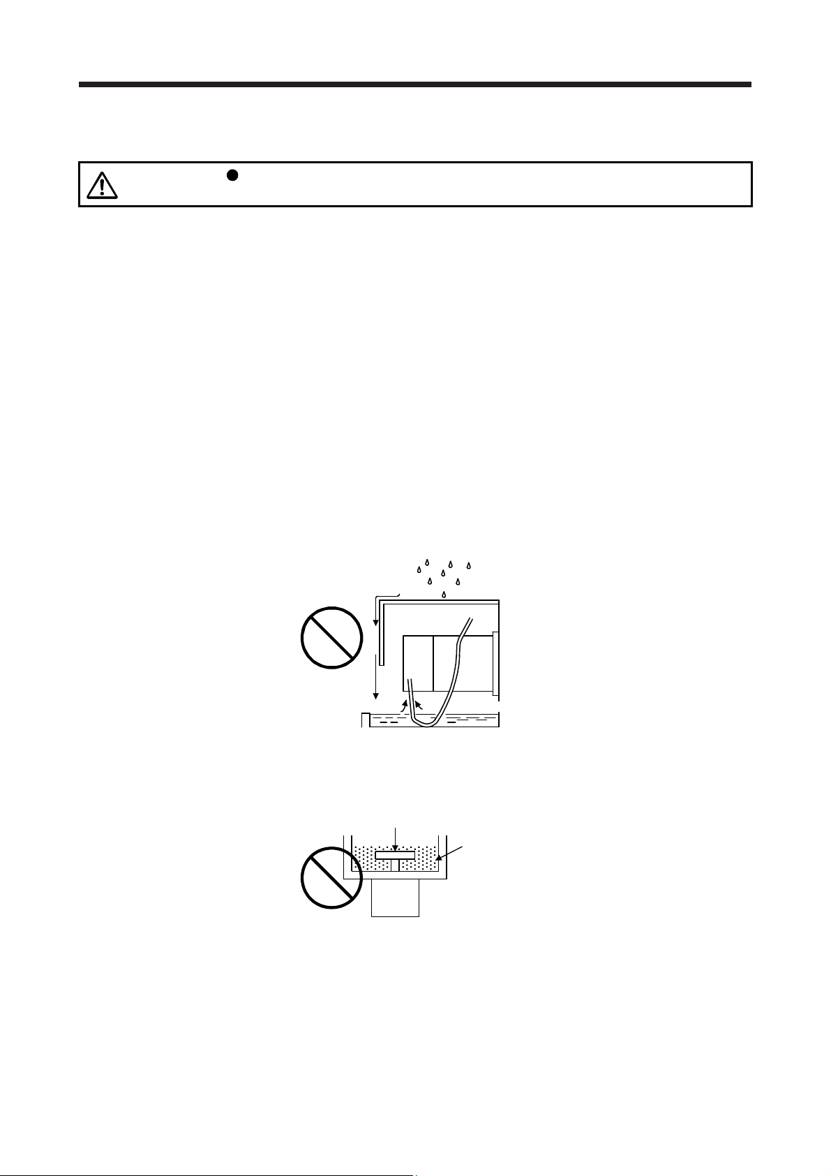
Provide adequate protection to prevent foreign matter, such as oil from entering the servo motor shaft. When
installing the servo motor, consider the items in this section.
(1) Do not use the servo motor with its cable soaked in oil or water.
Cover
Servo
motor
Oil/water pool
Capillary action
(2) When the servo motor is to be installed with the shaft end at top, provide measures so that it is not
exposed to oil and water entering from the machine side, gear box, etc.
Gear
Lubricating oil
Servo motor
(3) If oil such as cutting oil drops on the servo motor, the sealant, packing, cable and others may be affected
depending on the oil type.
(4) In the environment where the servo motor is exposed to oil mist, oil, water, grease and/or like, a
standard specifications servo motor may not be usable. Please contact your local sales office.
2 - 4
2. INSTALLATION
2.6 Cable
The power supply and encoder cables routed from the servo motor should be fixed to the servo motor to
keep them unmovable. Otherwise, the cable may disconnect. In addition, do not modify the connectors,
terminals and others at the ends of the cables.
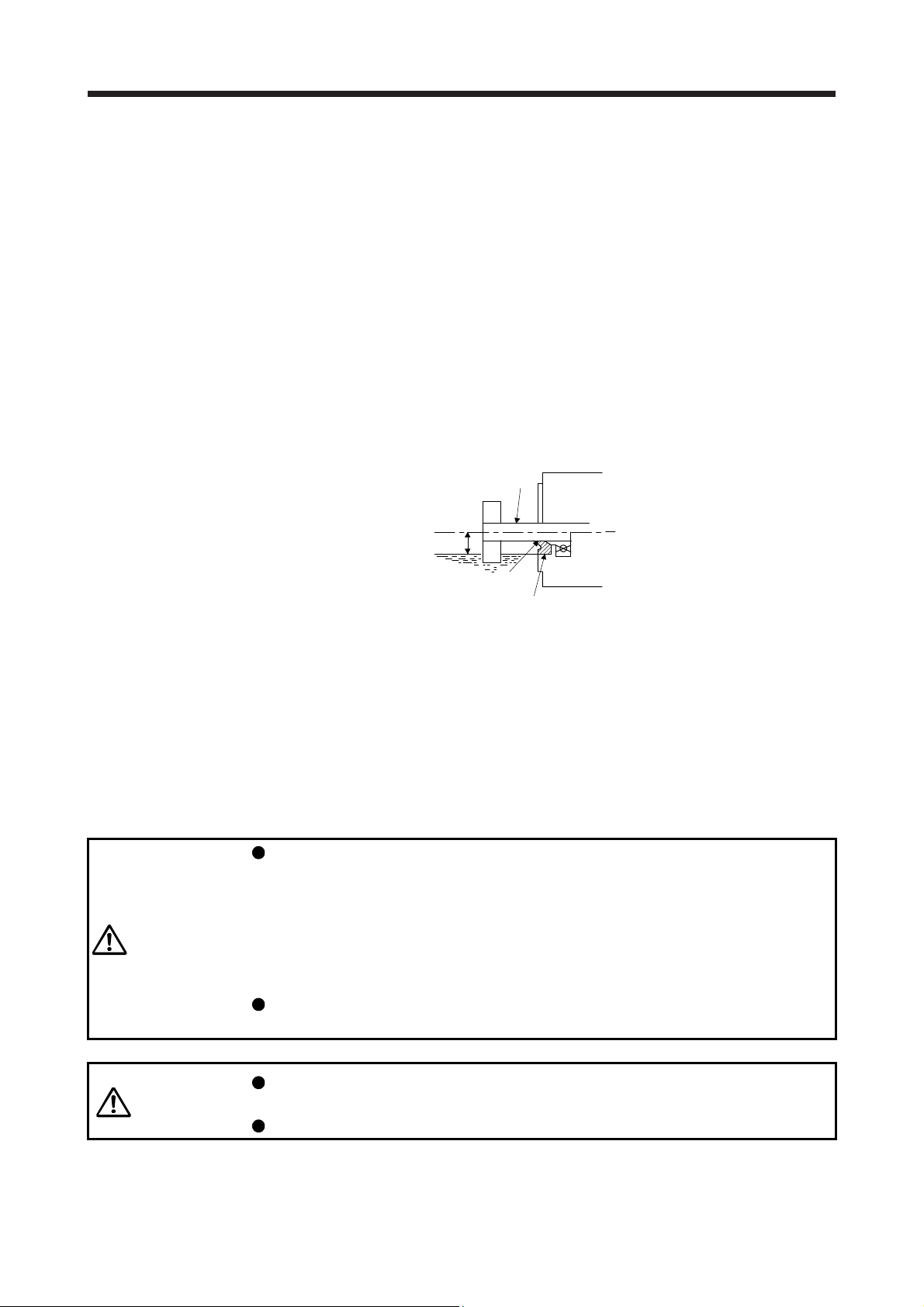
2.7 Servo motor with oil seal
For the servo motor with oil seal, the oil seal prevents the entry of oil into the servo motor. Make sure to
install it according in this section.
The functions have no problem even if the servo motor with oil seal may sound during operation.
(1) Pressure and oil level
Install the servo motor horizontally, and set the oil level in the gear box to be lower than the oil seal lip
always. If the oil level is higher than the oil seal lip, the oil enter the servo motor and may cause a
malfunction. Refer to the chapter of the servo motor series for the oil level.
Shaft
Gear
Servo motor
Height above oil level h
Lip
Oil seal
High pressure against the oil seal causes the abrasion and makes the life be short. Keep constant
internal pressure by equipping a ventilator to the gear box.
(2) Temperature
High temperature against the oil seal lip makes the life be short. Avoid exposing the oil seal lip to high
temperature oil since applicable temperature of the material is up to 100 °C and temperature of the oil
seal lip rises within 10 °C to 15 °C at maximum rotation.
2.8 Inspection items
Before starting maintenance and/or inspection, turn off the power and wait for 15
minutes or more (20 minutes or more for converter unit and drive unit) until the
charge lamp turns off. Then, confirm that the voltage between P+ and N- (L+ and
L- for converter unit and drive unit) is safe with a voltage tester and others.
WARNING
CAUTION
It is recommended that the following points periodically be checked.
(1) Check the bearings, brake section, etc. for unusual noise.
Otherwise, an electric shock may occur. In addition, when confirming whether the
charge lamp is off or not, always confirm it from the front of the servo amplifier
(converter unit).
To avoid an electric shock, only qualified personnel should attempt inspections.
For repair and parts replacement, contact your local sales office.
Do not perform insulation resistance test on the servo motor. Otherwise, it may
cause a malfunction.
Do not disassemble and/or repair the equipment on customer side.
2 - 5
2. INSTALLATION
(2) Check the cables and the like for scratches or cracks. Especially when the cable is movable, perform
periodic inspection according to operating conditions.
(3) Check the servo motor shaft and coupling for misalignment.
(4) Check the power supply connector and encoder connector tightening screws for looseness.
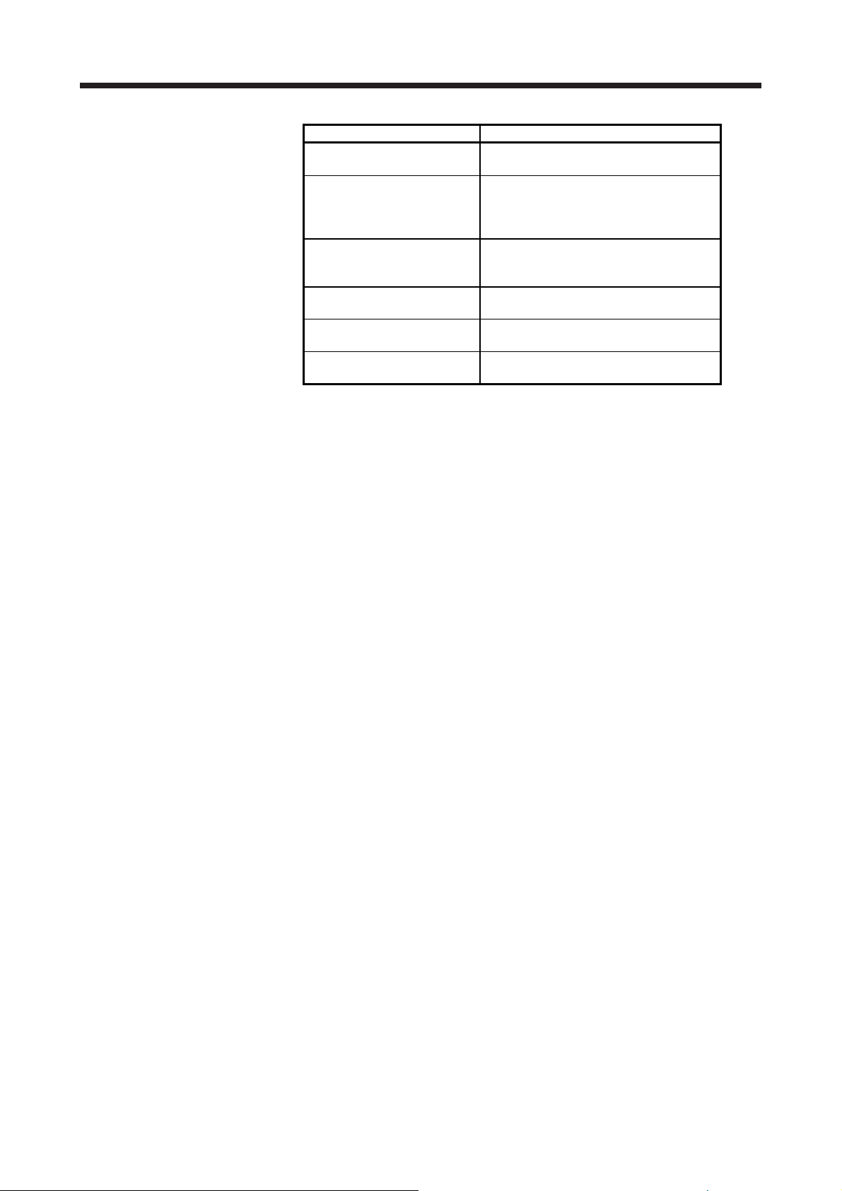
2.9 Parts having service lives
Service lives of the following parts are listed below. However, the service lives vary depending on operation
and environment. If any fault is found in the parts, they must be replaced immediately regardless of their
service lives. For parts replacement, please contact your local sales office.
(1) Bearings
When the servo motor is run at rated speed under rated load, bearings should be exchanged in 20,000
to 30,000 hours as a guideline. This differs on the operating conditions. The bearings must also be
changed if unusual noise or vibration is found during inspection.
(2) Oil seal (including oil seal used on the reducer)
Oil seals must be changed in 5,000 hours of operation at rated speed as a guideline. They must also be
changed if oil leakage, etc. is found during inspection.
The functions have no problem even if an oil seal may sound during operation.
2.10 Machine accuracies
Part name Life guideline
Bearings 20,000 hours to
30,000 hours
Encoder 20,000 hours to
30,000 hours
Cooling fan 20,000 hours
Oil seal 5000 hours
Reducer 10,000 hours to
20,000 hours
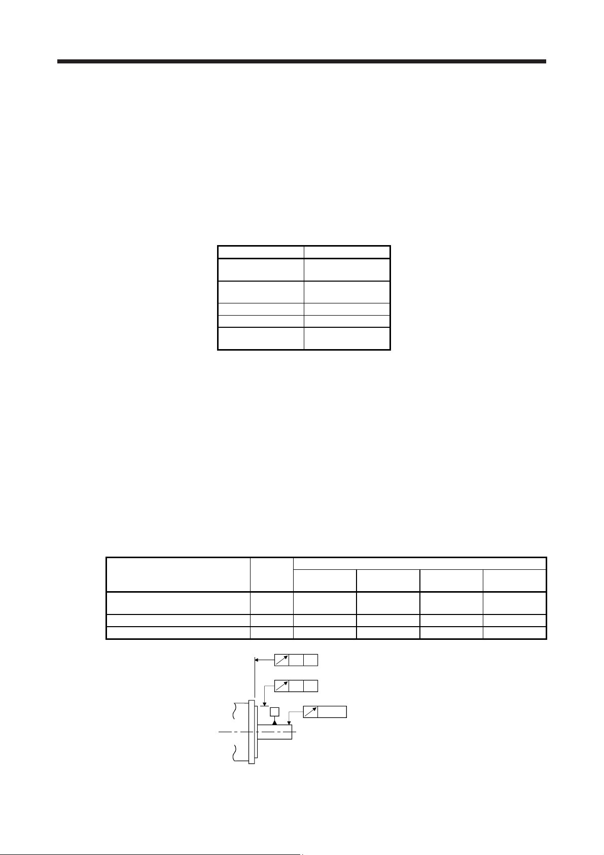
The following table indicates the machine accuracies of the servo motor around the output shaft and
mounting. (except the optional products)
Accuracy [mm]
Runout of flange surface to output
shaft
Runout of fitting OD of flange surface b) 0.04 0.04 0.06 0.08
Runout of output shaft end c) 0.02 0.02 0.03 0.03
Measuring
position
a) 0.05 0.06 0.08 0.08
Flange size
100 × 100 or
less
130 × 130
176 × 176 to
250 × 250
280 × 280 or
a)
A
b)
A
A
c)
2 - 6
more
3. CONNECTORS USED FOR SERVO MOTOR WIRING
r
r
3. CONNECTORS USED FOR SERVO MOTOR WIRING
POINT
The IP rating indicated is the connector's protection against ingress of dust and
water when the connector is connected to a servo motor. If the IP rating of the
connector and servo motor vary, the overall IP rating depends on the lowest IP
rating of all components.
3.1 Selection of connectors
Use the connector configuration products given in the table as the connectors for connection with the servo
motor. Refer to section 3.2 to 3.4 for the compatible connector configuration products.
(1) HG-MR series and HG-KR series
Electromagnetic brake connector
Power supply connector
Encoder connecto
Wiring connector
Servo motor
HG-MR_
HG-KR_
For encoder For power supply
Connector
configuration A
Connector
configuration B
For electromagnetic
brake
Connector
configuration C
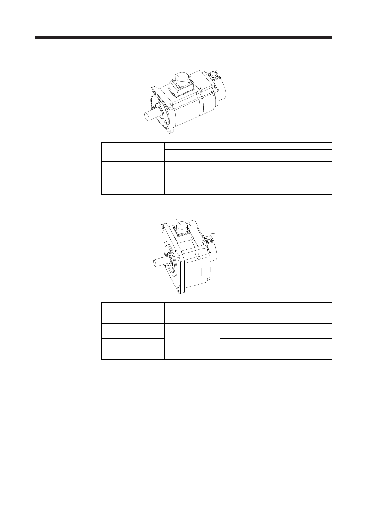
(2) HG-SR series
Electromagnetic brake connecto
Power supply connector
Encoder connector
Wiring connector
Servo motor
HG-SR51
HG-SR81
HG-SR52(4)
HG-SR102(4)
HG-SR152(4)
HG-SR121
HG-SR201
HG-SR301
HG-SR202(4)
HG-SR352(4)
HG-SR502(4)
HG-SR421
HG-SR702(4)
For encoder For power supply
Connector
configuration E
Connector
configuration D
Connector
configuration G
Connector
configuration H
For electromagnetic
brake
Connector
configuration F
3 - 1
3. CONNECTORS USED FOR SERVO MOTOR WIRING
r
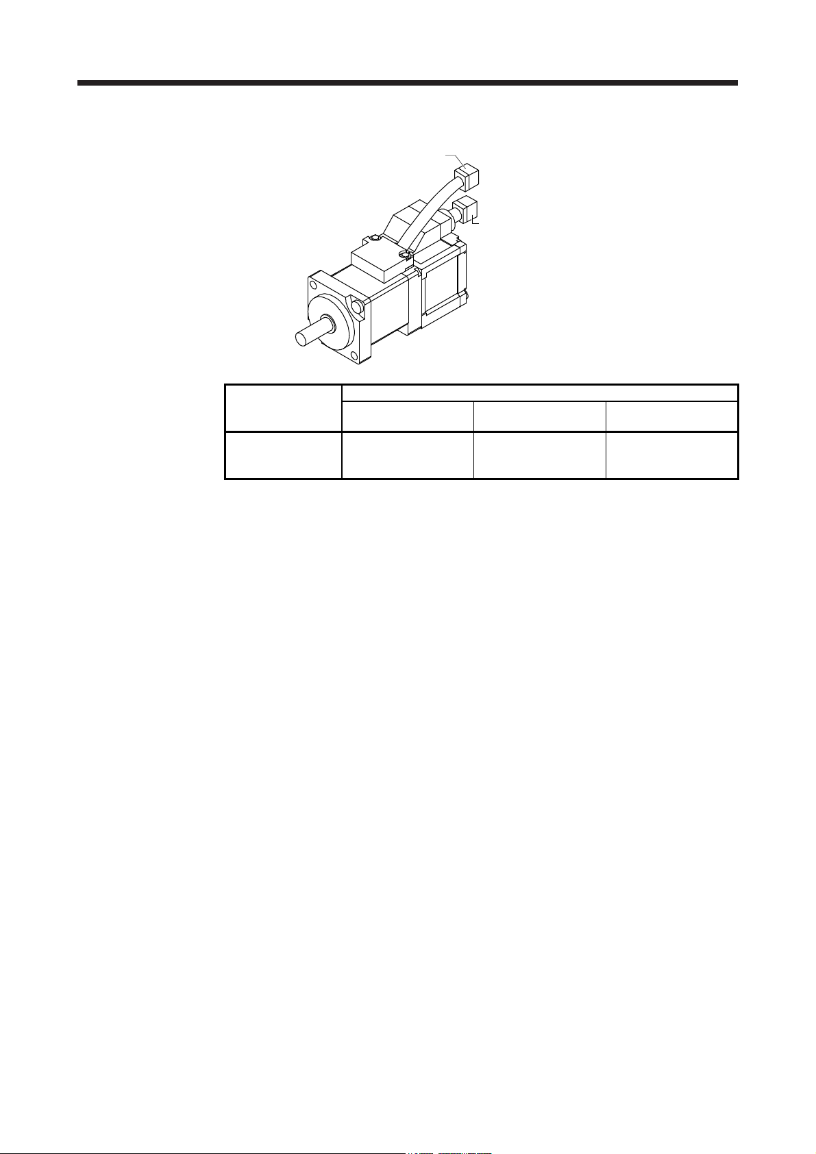
(3) HG-JR series
HG-JR53(4) to HG-JR903(4)/HG-JR701M(4) to HG-JR15K1M(4)/HG-JR601(4) to HG-JR12K1(4)
Electromagnetic brake connector
HG-JR22K1M(4) to HG-JR37K1M(4)/HG-JR45K1M4/HG-JR55K1M4/HG-JR15K1(4) to HG-JR37K1(4)
Cooling fan connecto
Encoder connector
Encoder connector
Power supply connector
Servo motor
HG-JR53(4)
HG-JR73(4)
HG-JR103(4)
HG-JR153(4)
HG-JR203(4)
HG-JR3534
HG-JR5034
HG-JR353
HG-JR503
HG-JR703(4)
HG-JR903(4)
HG-JR701M(4)
HG-JR11K1M(4)
HG-JR15K1M(4)
HG-JR601(4)
HG-JR801(4)
HG-JR12K1(4)
HG-JR22K1M(4)
HG-JR30K1M(4)
HG-JR37K1M(4)
HG-JR45K1M4
HG-JR55K1M4
HG-JR15K1(4)
HG-JR20K1(4)
HG-JR25K1(4)
HG-JR30K1(4)
HG-JR37K1(4)
For encoder For power supply
Connector
configuration E
Connector
configuration D
Connector
configuration G
Connector
configuration H
Connector
configuration K
None (terminal box)
Wiring connector
For electromagnetic
configuration F
configuration J
brake
Connector
Connector
For cooling fan
Connector
configuration L
3 - 2
3. CONNECTORS USED FOR SERVO MOTOR WIRING
r
r
(4) HG-RR series
Power connecto
Encoder connector
(5) HG-UR series
Servo motor
HG-RR103
HG-RR153
HG-RR203
HG-RR353
HG-RR503
Power connecto
For encoder For power supply
Connector
configuration D
Wiring connector
Connector
configuration N
Connector
configuration M
Encoder connector
For electromagnetic
brake
Sharing for power
supply
Wiring connector
Servo motor
HG-UR72
HG-UR152
HG-UR202
HG-UR352
HG-UR502
Note. Electromagnetic brake connector is not required since the power supply connector has a pin
assigned for electromagnetic brake.
For encoder For power supply
Connector
Connector
configuration D
configuration N
Connector
configuration M
For electromagnetic
brake
Sharing for power
supply (Note)
Connector
configuration J
3 - 3
3. CONNECTORS USED FOR SERVO MOTOR WIRING
r
(6) HG-AK series
Power connecto
Encoder connector
Wiring connector
Servo motor
HG-AK0136
HG-AK0236
HG-AK0336
Note.An electromagnetic brake connector is not required since the power connector has a pin assigned
for electromagnetic brake.
For encoder For power supply
Connector configuration P Connector configuration Q Sharing for power supply
For electromagnetic
brake
(Note)
3 - 4
3. CONNECTORS USED FOR SERVO MOTOR WIRING
3.2 Wiring connectors (connector configurations A/B/C)
Connector
configuration
A
(for encoder)
Feature
IP65
Connector: 2174053-1
(TE Connectivity)
Note. The other side connector
Connector
configuration
B
(for power supply)
Feature
Connector: KN4FT04SJ1-R
IP65
Contact: ST-TMH-S-C1B-100 (A534G)
Note. The other side connector
Connector Crimping tool
For ground clip: 1596970-1
For REC. contact: 1596847-1
(TE Connectivity)
Servo motor encoder
1674339-1
(TE Connectivity)
Connector Crimping tool
HOOD/SOCKET INSULATOR/
BUSHING/GROUND NUT
(JAE)
CT170-14-TMH5B
(JAE)
Servo motor power supply
JN4AT04NJ1
(JAE)
connector (Note)
connector (Note)
Connector
configuration
C
(for
electromagnetic
brake)
Feature
Connector: JN4FT02SJ1-R
IP65
Contact: ST-TMH-S-C1B-100 (A534G)
Note. The other side connector
Connector Crimping tool
HOOD/SOCKET INSULATOR/
BUSHING/GROUND NUT
(JAE)
CT170-14-TMH5B
(JAE)
Servo motor
electromagnetic brake
connector (Note)
JN4AT02PJ1
(JAE)
3 - 5

3. CONNECTORS USED FOR SERVO MOTOR WIRING
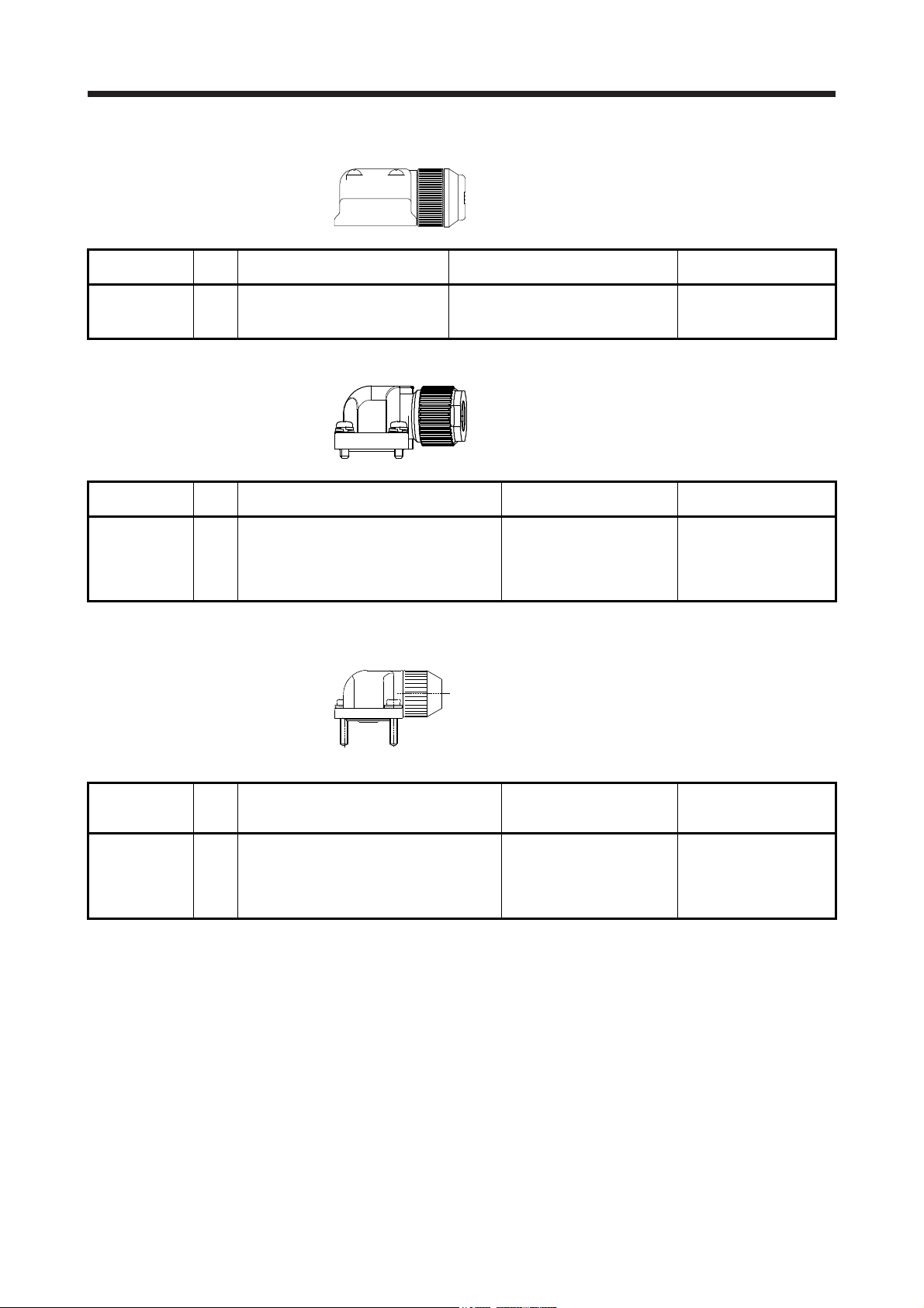
3.3 Wiring connectors (connector configurations D/E/F/G/H)
Angle plug
Straight plug
(one-touch connection type)
Straight plug
(screw type)
(one-touch connection type)
Angle plug
(screw type)
Connector
configuration
(for encoder)
Feature
D
IP67
Type Plug Socket contact Contact shape
Straight
Angle
Note. The other side connector
CMV1-SP10S-M1
(one-touch connection
type)
CMV1S-SP10S-M1
(screw type)
CMV1-SP10S-M2
(one-touch connection
type)
CMV1S-SP10S-M2
(screw type)
CMV1-AP10S-M1
(one-touch connection
type)
CMV1S-AP10S-M1
(screw type)
CMV1-AP10S-M2
(one-touch connection
type)
CMV1S-AP10S-M2
(screw type)
Plug (DDK)
CMV1-#22ASC-S1-100
CMV1-#22ASC-C1-100
CMV1-#22ASC-C2-100
CMV1-#22ASC-S1-100
CMV1-#22ASC-C1-100
CMV1-#22ASC-C2-100
CMV1-#22ASC-S1-100
CMV1-#22ASC-C1-100
CMV1-#22ASC-C2-100
CMV1-#22ASC-S1-100
CMV1-#22ASC-C1-100
CMV1-#22ASC-C2-100
Soldering type
Applicable wire size: AWG 20 or less
Crimping type
Applicable wire size: AWG 24 to 20
The crimping tool (357J-53162T) is
required.
Crimping type
Applicable wire size: AWG 28 to 24
The crimping tool (357J-53163T) is
required.
Soldering type
Applicable wire size: AWG 20 or less
Crimping type
Applicable wire size: AWG 24 to 20
The crimping tool (357J-53162T) is
required.
Crimping type
Applicable wire size: AWG 28 to 24
The crimping tool (357J-53163T) is
required.
Soldering type
Applicable wire size: AWG 20 or less
Crimping type
Applicable wire size: AWG 24 to 20
The crimping tool (357J-53162T) is
required.
Crimping type
Applicable wire size: AWG 28 to 24
The crimping tool (357J-53163T) is
required.
Soldering type
Applicable wire size: AWG 20 or less
Crimping type
Applicable wire size: AWG 24 to 20
The crimping tool (357J-53162T) is
required.
Crimping type
Applicable wire size: AWG 28 to 24
The crimping tool (357J-53163T) is
required.
Cable OD
[mm]
(reference)
5.5 to 7.5
7.0 to 9.0
5.5 to 7.5
7.0 to 9.0
Servo motor
encoder
connector
(Note)
CMV1-R10P
3 - 6

3. CONNECTORS USED FOR SERVO MOTOR WIRING
Plug Cable clamp Cable Plug Cable clamp Cable
Connector
configuration
E
(for power
supply)
Feature
IP67
EN compliant
(Note 1)
General
environment
Type Model
Straight
Angle
Straight
Angle
Note 1. Not comply with EN.
2. The other side connector
Plug (DDK) Cable clamp (DDK) Servo motor
CE05-6A18-10SD-D-BSS
Applicable wire size: AWG 14 to 12
CE05-8A18-10SD-D-BAS
Applicable wire size: AWG 14 to 12
D/MS3106B18-10S
Applicable wire size: AWG 14 to 12
D/MS3108B18-10S
Applicable wire size: AWG 14 to 12
Cabel OD
[mm] (reference)
8.5 to 11 CE3057-10A-2-D
10.5 to 14.1 CE3057-10A-1-D
8.5 to 11 CE3057-10A-2-D
10.5 to 14.1 CE3057-10A-1-D
14.3 or less
(bushing ID)
Model
D/MS3057-10A
power supply
connector
(Note 2)
MS3102A18-10P
3 - 7

3. CONNECTORS USED FOR SERVO MOTOR WIRING
Angle plug
Straight plug
(one-touch connection type)
Connector
configuration
(for electro-
magnetic
brake)
Feature
F
IP67
Type Plug Socket contact Contact shape
Straight
Angle
Note. The other side connector
CMV1-SP2S-S
(one-touch connection
type)
CMV1S-SP2S-S
(screw type)
CMV1-SP2S-M1
(one-touch connection
type)
CMV1S-SP2S-M1
(screw type)
CMV1-SP2S-M2
(one-touch connection
type)
CMV1S-SP2S-M2
(screw type)
CMV1-SP2S-L
(one-touch connection
type)
CMV1S-SP2S-L
(screw type)
CMV1-AP2S-S
(one-touch connection
type)
CMV1S-AP2S-S
(screw type)
CMV1-AP2S-M1
(one-touch connection
type)
CMV1S-AP2S-M1
(screw type)
CMV1-AP2S-M2
(one-touch connection
type)
CMV1S-AP2S-M2
(screw type)
CMV1-AP2S-L
(one-touch connection
type)
CMV1S-AP2S-L
(screw type)
Straight plug
(screw type)
Plug (DDK) Servo motor
CMV1-#22BSC-S2-100
CMV1-#22BSC-C3-100
CMV1-#22BSC-S2-100
CMV1-#22BSC-C3-100
CMV1-#22BSC-S2-100
CMV1-#22BSC-C3-100
CMV1-#22BSC-S2-100
CMV1-#22BSC-C3-100
CMV1-#22BSC-S2-100
CMV1-#22BSC-C3-100
CMV1-#22BSC-S2-100
CMV1-#22BSC-C3-100
CMV1-#22BSC-S2-100
CMV1-#22BSC-C3-100
CMV1-#22BSC-S2-100
CMV1-#22BSC-C3-100
(one-touch connection type)
Soldering type
Applicable wire size: AWG 16 or less
Crimping type
Applicable wire size: AWG 20 to 16
The crimping tool (357J-53164T) is
required.
Soldering type
Applicable wire size: AWG 16 or less
Crimping type
Applicable wire size: AWG 20 to 16
The crimping tool (357J-53164T) is
required.
Soldering type
Applicable wire size: AWG 16 or less
Crimping type
Applicable wire size: AWG 20 to 16
The crimping tool (357J-53164T) is
required.
Soldering type
Applicable wire size: AWG 16 or less
Crimping type
Applicable wire size: AWG 20 to 16
The crimping tool (357J-53164T) is
required.
Soldering type
Applicable wire size: AWG 16 or less
Crimping type
Applicable wire size: AWG 20 to 16
The crimping tool (357J-53164T) is
required.
Soldering type
Applicable wire size: AWG 16 or less
Crimping type
Applicable wire size: AWG 20 to 16
The crimping tool (357J-53164T) is
required.
Soldering type
Applicable wire size: AWG 16 or less
Crimping type
Applicable wire size: AWG 20 to 16
The crimping tool (357J-53164T) is
required.
Soldering type
Applicable wire size: AWG 16 or less
Crimping type
Applicable wire size: AWG 20 to 16
The crimping tool (357J-53164T) is
required.
Cable OD
[mm]
(reference)
4.0 to 6.0
5.5 to 7.5
7.0 to 9.0
9.0 to 11.6
4.0 to 6.0
5.5 to 7.5
7.0 to 9.0
9.0 to 11.6
Angle plug
(screw type)
electro-
magnetic brake
connector
(Note)
CMV1-R2P
3 - 8

3. CONNECTORS USED FOR SERVO MOTOR WIRING
Plug Cable clamp Cable Plug Cable clamp Cable
Connector
configuration
G
(for power
supply)
Feature
IP67
EN compliant
(Note 1)
General
environment
Type Model
Straight
Angle
Straight
Angle
Plug (DDK) Cable clamp (DDK) Servo motor
CE05-6A22-22SD-D-BSS
Applicable wire size: AWG 10 to 8
CE05-8A22-22SD-D-BAS
Applicable wire size: AWG 10 to 8
D/MS3106B22-22S
Applicable wire size: AWG 10 to 8
D/MS3108B22-22S
Applicable wire size: AWG 10 to 8
Cabel OD
[mm] (reference)
9.5 to 13 CE3057-12A-2-D
12.5 to 16 CE3057-12A-1-D
9.5 to 13 CE3057-12A-2-D
12.5 to 16 CE3057-12A-1-D
15.9 or less
(bushing ID)
Model
D/MS3057-12A
power supply
connector
(Note 2)
MS3102A22-22P
Note 1. Not comply with EN.
2. The other side connector
Plug Cable clamp Cable Plug Cable clamp Cable
Backshell
Connector
configuration
H
(for power
supply)
Feature
IP67
EN compliant
(Note 1)
General
environment
Type Model Model
Straight
Angle
Straight
Angle
Plug (DDK) Backshell Cable clamp (DDK) Servo motor
power supply
MS3102A32-17P
(Note 3)
CE05-6A32-17SD-D
Applicable wire size: AWG 4
CE05-6A32-17SD-D-BSS
Applicable wire size: AWG 6 to 4
CE05-8A32-17SD-D-BAS
Applicable wire size: AWG 6 to 4
D/MS3106B32-17S
Applicable wire size: AWG 6 to 4
D/MS3108B32-17S
Applicable wire size: AWG 6 to 4
CE05-32BS-S-D-OB
Cabel OD
[mm] (reference)
30 to 32.5 CE3057-24A-1-D
27 to 29.6 CE3057-24A-2-D
22 to 23.8 CE3057-20A-1-D
23.8 or less
(bushing ID)
Model
D/MS3057-20A
connector
(Note 2)
Note 1. Not comply with EN.
2. The other side connector
3. This connector is used only when the outer diameter of the cable used for HG-JR11K1M(4) and HG-JR15K1M(4) exceeds
23.8 mm.
3 - 9

3. CONNECTORS USED FOR SERVO MOTOR WIRING
3.4 Wiring connectors (connector configurations J/K/L/M/N/P/Q)
Plug Cable
Connector for cable
IP67 compatible IP67 compatible General environmental
Connector
configuration
J
(for
electro-
magnetic
brake)
Feature
IP67
EN
UL/CSA
compliant
(Note1)
General
environment
D/MS3106A10SL-4S
(D190)
Applicable wire size:
D/MS3106A10SL-4S
Applicable wire size:
Note 1. Not comply with EN.
2. The connector to be mated.
Plug
Plug (DDK)
AWG 22 to 16
AWG 22 to 16
Cable
clamp
Connector for cable Cable Plug
Plug
Cable-side connector
Connector for cable
Type Manufacturer
Straight
Angle
Straight
Nippon Flex
Daiwa Dengyo 5 to 8.3 YSO10-5 to 8
Nippon Flex
Daiwa Dengyo 5 to 8.3 YLO10-5 to 8
Cable
Backshell Cable
Cable OD
[mm]
(reference)
4 to 8
8 to 12
4 to 8
8 to 12
5.6 or less
(bushing ID)
Model
ACS-08RLMS10F
ACS-12RLMS10F
ACA-08RLMS10F
ACA-12RLMS10F
D/MS3057-4A
Cable
clamp
electromagnetic
MS3102A10SL4P
Cable
Servo motor
brake
connector
(Note 2)
Backshell
Connector
configuration
K
(for
encoder)
Feature
IP67
EN
compliant
(Note 1)
General
environment
Type Model
Straight
Angle CE-20BA-S-D
Straight D/MS3106B20-29S
Angle D/MS3108B20-29S
Note 1. Not comply with EN.
2. The connector to be mated.
Plug (DDK)
D/MS3106A20-29S (D190)
Plug
Backshell
(DDK)
CE02-20BS-S-D
Cable clamp
Cable clamp (DDK) Servo motor
Cable OD
[mm]
6.8 to 10 CE3057-12A-3-D
15.9 or less
(bushing ID)
Model
D/MS3057-12A
encoder
connector
(Note 2)
D/MS3102A2029P
3 - 10

3. CONNECTORS USED FOR SERVO MOTOR WIRING
Cable
Plug
clamp
Connector
configuration
L
(for
cooling
fan)
Feature
IP67
EN
compliant
Type Model
Straight
Note. The connector to be mated.
Plug Cable clamp Cable Plug Cable clamp Cable
Connector
configuration
M
(for power
supply)
Feature
IP65
EN
UL/CSA
compliant
General
environment
UL/CSA
compliant
Type Model
Straight
Angle
Straight
Angle
Note. The connector to be mated.
Plug (DDK) Cable clamp
Cable OD
[mm] (reference)
CE05-6A14S-2SD-D
Applicable wire size: AWG 22 to 16
Plug (DDK) Cable clamp (DDK)
CE05-6A24-10SD-D-BSS
Applicable wire size: AWG 10 to 8
CE05-8A24-10SD-D-BAS
Applicable wire size: AWG 10 to 8
D/MS3106B24-10S
Applicable wire size: AWG 10 to 8
D/MS3108B24-10S
Applicable wire size: AWG 10 to 8
8.3 to 11.3
Cable OD
[mm] (reference)
13 to 15.5 CE3057-16A-2-D
15 to 19.1 CE3057-16A-1-D
13 to 15.5 CE3057-16A-2-D
15 to 19.1 CE3057-16A-1-D
19.1 or less
(bushing ID)
Model
YSO14-9 to 11
(Daiwa Dengyo)
Model
D/MS3057-16A
Servo motor
cooling fan
connector (Note)
CE05-2A14S-2P
Servo motor
power supply
connector (Note)
CE05-2A24-10P
3 - 11

3. CONNECTORS USED FOR SERVO MOTOR WIRING
Plug Cable clamp Cable Plug Cable clamp Cable
Connector
configuration
N
(for power
supply)
Feature
IP65
EN
UL/CSA
compliant
General
environment
UL/CSA
compliant
Type Model
Straight
Angle
Straight
Angle
Note. The connector to be mated.
Connector
configuration
P
(for
encoder)
Feature
General
environment
(Note 1)
Tab housing Tab contact Applicable wire size
J21DPM-10V-KX
Note. Not comply with EN.
Plug (DDK) Cable clamp (DDK)
Cable OD
[mm] (reference)
CE05-6A22-23SD-D-BSS
Applicable wire size: AWG 14 to 12
CE05-8A22-23SD-D-BAS
Applicable wire size: AWG 14 to 12
D/MS3106B22-23S
Applicable wire size: AWG 14 to 12
D/MS3108B22-23S
Applicable wire size: AWG 14 to 12
9.5 to 13 CE3057-12A-2-D
12.5 to 16 CE3057-12A-1-D
9.5 to 13 CE3057-12A-2-D
12.5 to 16 CE3057-12A-1-D
15.9 or less
(bushing ID)
Model
D/MS3057-12A
Servo motor
power supply
connector (Note)
CE05-2A22-23P
Connector (JST)
SJ2M-01GFM1.0N
2
to 0.50
0.20 mm
2
mm
(AWG 24 to 20)
Insulator OD
[mm]
1.11 to 1.53 YRS-8861 J21DF-10V-KX-L
Crimping tool
Servo motor
encoder connector
Connector
configuration
Q
(for power
supply)
Feature
General
environment
(Note 1)
Note. Not comply with EN.
Connector (JST)
Tab housing Tab contact Applicable wire size
2
J21DPM-06V-KX
SJ2M-21GFM1.0N
0.30 mm
2
mm
to 0.75
Insulator OD
[mm]
1.30 to 1.90 YRF-1120 J21DF-06V-KX-L
Crimping tool
Servo motor power
connector
3 - 12

4. CONNECTION OF SERVO AMPLIFIER AND SERVO MOTOR
4. CONNECTION OF SERVO AMPLIFIER AND SERVO MOTOR
Any person who is involved in wiring should be fully competent to do the work.
Ground the servo motor securely.
Do not attempt to wire the servo motor until it has been mounted. Otherwise, it
WARNING
CAUTION
may cause an electric shock.
The cables should not be damaged, stressed, loaded, or pinched. Otherwise, it
may cause an electric shock.
To avoid an electric shock, insulate the connections of the power supply
terminals.
Wire the equipment correctly and securely. Otherwise, the servo motor may
operate unexpectedly, resulting in injury.
Connect cables to the correct terminals. Otherwise, a burst, damage, etc. may
occur.
Ensure that polarity (+/-) is correct. Otherwise, a burst, damage, etc. may occur.
Do not install a power capacitor, surge killer or radio noise filter (FR-BIF-(H)
option) with the power line of the servo motor.
Do not modify the equipment.
Connect the servo amplifier (converter unit) power output (U, V, and W) to the
servo motor power input (U, V, and W) directly. Do not let a magnetic contactor,
etc. intervene. Otherwise, it may cause a malfunction.
Servo amplifier
(converter unit)
U
V
W
Servo motor
U
V
W
M
Servo amplifier
(converter unit)
U
V
W
Servo motor
U
V
W
M
POINT
We recommend using HIV wires to connect the servo amplifier (converter unit)
to the servo motor. Therefore, recommended wire sizes may different from those
of the used wires for the previous servo motors.
When you use a drive unit, "servo amplifier" explained above will be "drive unit".
4 - 1

4. CONNECTION OF SERVO AMPLIFIER AND SERVO MOTOR
4.1 Connection instructions
To avoid a malfunction, connect the wires to the correct phase terminals (U, V,
and W) of the servo amplifier (converter unit) and servo motor.
Do not connect AC power supply directly to the servo motor. Otherwise, it may
cause a malfunction.
CAUTION
For grounding, connect the grounding lead wire from the servo motor to the protective earth (PE) terminal of
the servo amplifier (converter unit), and then connect the wire from the servo amplifier (converter unit) to the
ground via the protective earth of the cabinet. Do not connect the wire directly to the protective earth of the
cabinet.
Do not use the 24 V DC interface power supply for the electromagnetic brake.
Always use the power supply designed exclusively for the electromagnetic brake.
Otherwise, it may cause a malfunction.
POINT
Refer to chapter 5 for the selection of the encoder cable.
Refer to the chapter of the servo motor series for the selection of a surge
absorber for the electromagnetic brake.
Cabinet
Servo amplifier
(converter unit)
Servo motor
PE
terminal
(Note)
Note. The number of PE terminals of the servo amplifier (converter unit) differs depending
()
(E)
on the amplifier types.
(
)
4 - 2

4. CONNECTION OF SERVO AMPLIFIER AND SERVO MOTOR
r
r
4.2 Wiring
4.2.1 HG-MR series/HG-KR series servo motor
(1) Connection with MR-J4 1-axis servo amplifier
(a) Servo motor power supply cable wiring diagrams
1) When cable length is 10 m or less
10 m or less
MR-PWS1CBL_M-A1-L
MR-PWS1CBL_M-A2-L
Servo amplifier
CNP3
U
V
MR-PWS1CBL_M-A1-H
MR-PWS1CBL_M-A2-H
(Red)
(White)
(Black)
(Green/yellow)
2) When cable length exceeds 10 m
Fabricate an extension cable as shown below. In addition, the motor power supply cable should
be within 2 m.
Refer to section 4.3 for the wire used for the extension cable.
50 m or less 2 m or less
Extension cable
Servo amplifier
CNP3
U
V
Servo moto
U
M
V
WW
MR-PWS1CBL2M-A1-L
MR-PWS1CBL2M-A2-L
MR-PWS1CBL2M-A1-H
MR-PWS1CBL2M-A2-H
MR-PWS2CBL03M-A1-L
MR-PWS2CBL03M-A2-L
(Red)
(White)
(Black)
(Green/yellow)
Servo moto
U
V
WW
M
(Note)
a) Junction connector for
extension cable
Note. Use of the following connectors is recommended when ingress protection (IP65) is necessary.
(Note)
b) Junction connector for
motor power supply cable
Junction connector
a) Junction connector for
extension cable
b)
Junction connector for
motor power supply cable
Connector: RM15WTPZ-4P(71)
Cord clamp: JR13WCC-5(72)
(Hirose Electric)
Connector: RM15WTJZ-4S(71)
Cord clamp: JR13WCC-8(72)
(Hirose Electric)
Description IP rating
IP65
Numeral changes depending on the cable OD.
IP65
Numeral changes depending on the cable OD.
4 - 3

4. CONNECTION OF SERVO AMPLIFIER AND SERVO MOTOR
(b) Electromagnetic brake cable wiring diagrams
1) When cable length is 10 m or less
10 m or less
MR-BKS1CBL_M-A1-L
MR-BKS1CBL_M-A2-L
(Note 3)
24 V DC power supply
for electromagnetic
brake
Note 1. Connect a surge absorber as close to the servo motor as possible.
2. There is no polarity in electromagnetic brake terminals (B1 and B2).
3. Do not use the 24 V DC interface power supply for the electromagnetic brake.
4. Create the circuit in order to shut off by interlocking with the emergency stop switch.
MBR
(Electromagnetic
brake interlock)
ALM
(Malfunction)
(Note 4)
(Note 1)
When fabricating the electromagnetic brake cable MR-BKS1CBL-_M-_, refer to section 5.5 and
5.6.
2) When cable length exceeds 10 m
Fabricate an extension cable as shown below. In addition, the electromagnetic brake cable
should be within 2 m.
Refer to section 4.3 for the wire used for the extension cable.
50 m or less
Extension cable
(To be fabricated)
(Note 5)
24 V DC power supply
for electromagnetic
brake
MBR
(Electromagnetic
brake interlock)
ALM
(Malfunction)
(Note 3)
(Note 1)
MR-BKS1CBL_M-A1-H
MR-BKS1CBL_M-A2-H
U
MR-BKS1CBL2M-A1-L
MR-BKS1CBL2M-A2-L
MR-BKS1CBL2M-A1-H
MR-BKS1CBL2M-A2-H
MR-BKS2CBL03M-A1-L
MR-BKS2CBL03M-A2-L
U
AWG20
AWG20
2 m or less
AWG20
AWG20
Servo motor
(Note 2)
B1
B
B2
Servo motor
(Note 4)
B1
B
B2
(Note 2)
a) Junction connector for
extension cable
Note 1. Connect a surge absorber as close to the servo motor as possible.
2. Use of the following connectors is recommended when ingress protection (IP65) is necessary.
Junction connector Description IP rating
a)
Junction connector for
extension cable
b)
Junction connector for
electromagnetic brake cable
3. Create the circuit in order to shut off by interlocking with the emergency stop switch.
4. There is no polarity in electromagnetic brake terminals (B1 and B2).
5. Do not use the 24 V DC interface power supply for the electromagnetic brake.
CM10-CR2P- (DDK)
Wire size: S, M, L
CMV1-SP2S- (DDK)
Wire size: S, M1, M2, L
(Note 2)
b) Junction connector for
electromagnetic brake cable
IP65
IP65
4 - 4

4. CONNECTION OF SERVO AMPLIFIER AND SERVO MOTOR
(2) Connection with MR-J4 multi-axis servo amplifier
(a) Servo motor power supply cable wiring diagrams
1) When cable length is 10 m or less
10 m or less
MR-PWS1CBL_M-A1-L
MR-PWS1CBL_M-A2-L
MR-PWS1CBL_M-A1-H
MR-PWS1CBL_M-A2-H
CNP3A/CNP3B/
CNP3C
(Note)
Note. CNP3 is for the MR-J4 3-axis servo amplifier.
U
V
W
(Red)
(White)
(Black)
(Green/yellow)
2) When cable length exceeds 10 m
Fabricate an extension cable as shown below. In addition, the motor power supply cable should
be within 2 m.
Refer to section 4.3 for the wire used for the extension cable.
50 m or less 2 m or less
MR-PWS1CBL2M-A1-L
MR-PWS1CBL2M-A2-L
MR-PWS1CBL2M-A1-H
MR-PWS1CBL2M-A2-H
MR-PWS2CBL03M-A1-L
MR-PWS2CBL03M-A2-L
(Green/yellow)
CNP3A/CNP3B/
CNP3C
(Note 1)
Extension cable
U
V
W
Servo motorServo amplifier
U
V
W
(Red)
(White)
(Black)
M
Servo motorServo amplifier
U
V
W
M
(Note 2)
a) Junction connector for
extension cable
Note 1. CNP3 is for the MR-J4 3-axis servo amplifier.
2. Use of the following connectors is recommended when ingress protection (IP65) is necessary.
Junction connector
a) Junction connector for
extension cable
b)
Junction connector for
motor power supply cable
Connector: RM15WTPZ-4P(71)
Cord clamp: JR13WCC-5(72)
(Hirose Electric)
Connector: RM15WTJZ-4S(71)
Cord clamp: JR13WCC-8(72)
(Hirose Electric)
Description IP rating
Numeral changes depending on the cable OD.
Numeral changes depending on the cable OD.
(Note 2)
b) Junction connector for
motor power supply cable
IP65
IP65
4 - 5

4. CONNECTION OF SERVO AMPLIFIER AND SERVO MOTOR
(b) Electromagnetic brake cable wiring diagrams
1) When cable length is 10 m or less
10 m or less
MR-BKS1CBL_M-A1-L
(Note 4)
24 V DC power supply
for electromagnetic
brake
(Note 3)
CALM
(AND
malfunction)
MBR-A
(Electromagnetic
brake interlock
for A-axis)
MBR-B
(Electromagnetic
brake interlock
for B-axis)
MBR-C
(Electromagnetic
brake interlock
for C-axis)
(Note 1)
(Note 1)
(Note 1)
MR-BKS1CBL_M-A2-L
MR-BKS1CBL_M-A1-H
MR-BKS1CBL_M-A2-H
AWG20
U
U
U
AWG20
MR-BKS1CBL_M-A1-L
MR-BKS1CBL_M-A2-L
MR-BKS1CBL_M-A1-H
MR-BKS1CBL_M-A2-H
AWG20
AWG20
MR-BKS1CBL_M-A1-L
MR-BKS1CBL_M-A2-L
MR-BKS1CBL_M-A1-H
MR-BKS1CBL_M-A2-H
AWG20
AWG20
Servo motor
(Note 2)
B1
B
B2
Servo motor
(Note 2)
B1
B
B2
Servo motor
(Note 2)
B1
B
B2
(Note 5)
Note 1. Connect a surge absorber as close to the servo motor as possible.
2. There is no polarity in electromagnetic brake terminals (B1 and B2).
3. Create the circuit in order to shut off by interlocking with the emergency stop switch.
4. Do not use the 24 V DC interface power supply for the electromagnetic brake.
5. This connection is for the MR-J4 3-axis servo amplifier.
When fabricating the electromagnetic brake cable MR-BKS1CBL-_M-_, refer to section 5.5 and
5.6.
4 - 6

4. CONNECTION OF SERVO AMPLIFIER AND SERVO MOTOR
2) When cable length exceeds 10 m
Fabricate an extension cable as shown below. In addition, the electromagnetic brake cable
should be within 2 m.
Refer to section 4.3 for the wire used for the extension cable.
2 m or less50 m or less
MR-BKS1CBL2M-A1-L
MR-BKS1CBL2M-A2-L
MR-BKS1CBL2M-A1-H
MR-BKS1CBL2M-A2-H
(Note 5)
24 V DC power supply
for electromagnetic
brake
(Note 3)
CALM
(AND
malfunction)
MBR-A
(Electromagnetic
brake interlock
for A-axis)
(Note 1)
U
MR-BKS2CBL03M-A1-L
MR-BKS2CBL03M-A2-L
AWG20
AWG20
Servo motor
(Note 4)
B1
B
B2
(Note 2)
a) Junction connector for
extension cable
MBR-B
(Electromagnetic
brake interlock
for B-axis)
(Note 1)
(Note 2)
a) Junction connector for
extension cable
MBR-C
(Electromagnetic
brake interlock
for C-axis)
(Note 1)
(Note 2)
a) Junction connector for
extension cable
(Note 2)
b) Junction connector for
electromagnetic brake cable
MR-BKS1CBL2M-A1-L
MR-BKS1CBL2M-A2-L
MR-BKS1CBL2M-A1-H
MR-BKS1CBL2M-A2-H
MR-BKS2CBL03M-A1-L
MR-BKS2CBL03M-A2-L
U
(Note 2)
b) Junction connector for
electromagnetic brake cable
MR-BKS1CBL2M-A1-L
MR-BKS1CBL2M-A2-L
MR-BKS1CBL2M-A1-H
MR-BKS1CBL2M-A2-H
MR-BKS2CBL03M-A1-L
MR-BKS2CBL03M-A2-L
U
(Note 2)
b) Junction connector for
electromagnetic brake cable
AWG20
AWG20
AWG20
AWG20
Servo motor
(Note 4)
B1
B
B2
Servo motor
(Note 4)
B1
B
B2
(Note 6)
Note 1. Connect a surge absorber as close to the servo motor as possible.
2. Use of the following connectors is recommended when ingress protection (IP65) is necessary.
Junction connector Description IP rating
a)
Junction connector for
extension cable
b)
Junction connector for
electromagnetic brake cable
3. Create the circuit in order to shut off by interlocking with the emergency stop switch.
4. There is no polarity in electromagnetic brake terminals (B1 and B2).
5. Do not use the 24 V DC interface power supply for the electromagnetic brake.
6. This connection is for the MR-J4 3-axis servo amplifier.
CM10-CR2P- (DDK)
Wire size: S, M, L
CMV1-SP2S- (DDK)
Wire size: S, M1, M2, L
IP65
IP65
4 - 7

4. CONNECTION OF SERVO AMPLIFIER AND SERVO MOTOR
4.2.2 HG-SR series/HG-JR series/HG-RR series/HG-UR series servo motor
Refer to section 4.3 for the wires used for wiring.
(1) Wiring diagrams
(a) Connection with MR-J4 1-axis servo amplifier
50 m or less
Servo amplifier
Servo motor
(Note 4)
Power supply
cooling fan
U
V
W
U
V
M
W
MCCB
BU
(Note 2)
24 V DC power supply
for electromagnetic
brake
Note 1. There is no polarity in electromagnetic brake terminals (B1 and B2).
2. Do not use the 24 V DC interface power supply for the electromagnetic brake.
3. Create the circuit in order to shut off by interlocking with the emergency stop switch.
4. Refer to the chapter of the servo motor series for the cooling fan power supply.
MBR
(Electromagnetic
brake interlock)
RA2
ALM
(Malfunction)
RA1
(Note 3)
RA3
Cooling fan
B1
U
B2
BV
BW
(Note 1)
B
4 - 8

4. CONNECTION OF SERVO AMPLIFIER AND SERVO MOTOR
(b) Connection with MR-J4 multi-axis servo amplifier
Servo amplifier
CNP3A
U
V
W
(Note 2)
24 V DC power supply
for electromagnetic
brake
50 m or less
(Note 3)
CALM
(AND
malfunction)
RA1
MBR-A
(Electromagnetic
brake interlock
for A-axis)
RA2
MBR-B
(Electromagnetic
brake interlock
for B-axis)
RA3
U
U
A-axis servo motor
U
M
V
W
(Note 1)
B1
B
B2
B-axis servo motor
(Note 1)
B1
B
B2
CNP3B
W
U
V
U
M
V
W
MBR-C
(Electromagnetic
brake interlock
for C-axis)
RA4
C-axis servo motor
(Note 1)
B1
B2
B
U
CNP3C
U
V
W
U
M
V
W
Note 1. There is no polarity in electromagnetic brake terminals (B1 and B2).
2. Do not use the 24 V DC interface power supply for the electromagnetic brake.
3. Create the circuit in order to shut off by interlocking with the emergency stop switch.
4 - 9

4. CONNECTION OF SERVO AMPLIFIER AND SERVO MOTOR
(2) Servo motor terminal section
The following table shows the servo motor terminal section. For details of the connectors, refer to (3) of
this section. For details of the terminal box, refer to (4) of this section.
The connector fitting the servo motor is prepared as options. Refer to chapter 5 for details of the options.
For types other than those prepared as options, refer to chapter 3.
(a) HG-SR series
(b) HG-JR series
Servo motor
HG-JR53(4)
HG-JR73(4)
HG-JR103(4)
HG-JR153(4)
HG-JR203(4)
HG-JR3534
HG-JR5034
HG-JR353
HG-JR503
HG-JR703(4)
HG-JR903(4)
HG-JR701M(4)
HG-JR11K1M(4)
HG-JR15K1M(4)
HG-JR601(4)
HG-JR801(4)
HG-JR12K1(4)
HG-JR22K1M(4)
HG-JR30K1M(4)
HG-JR37K1M(4)
HG-JR45K1M4
HG-JR55K1M4
HG-JR15K1(4)
HG-JR20K1(4)
HG-JR25K1(4)
HG-JR30K1(4)
HG-JR37K1(4)
Servo motor
HG-SR52(4)
HG-SR102(4)
HG-SR152(4)
HG-SR51
HG-SR81
HG-SR202(4)
HG-SR352(4)
HG-SR502(4)
HG-SR121
HG-SR201
HG-SR301
HG-SR702(4)
HG-SR421
Encoder Power
Connector A
Connector B Connector J
Connector L Terminal box Connector K
Encoder Power
Connector A
Servo motor terminal section
Connector C
Connector D
Connector E
Servo motor terminal section
Connector C
Connector D
Connector E
Electromagnetic
brake
Connector H
Electromagnetic
brake
Connector H
Cooling fan
4 - 10

4. CONNECTION OF SERVO AMPLIFIER AND SERVO MOTOR
(c) HG-RR series
Servo motor
HG-RR103
HG-RR153
HG-RR203
HG-RR353
HG-RR503
Encoder Power
Connector A
(d) HG-UR series
Servo motor
HG-UR72
HG-UR152
HG-UR202
HG-UR352
HG-UR502
Encoder Power
Connector A
(3) Details of servo motor-side connectors
The followings show the encoder connector, power connector, electromagnetic brake connector, and
cooling fan connector viewed from the connection side.
Connector A
Connector B
Servo motor terminal section
Connector F
Connector G
Servo motor terminal section
Connector F
Connector G Connector J
Connector C
Electromagnetic
The connector for
power is shared
Electromagnetic
The connector for
power is shared
brake
brake
Encoder connector
CMV1-R10P
Terminal
7
10
9
8
3
6
2
5
1
4
L
M
N SHD
P
R LG
S P5
T
No.
1 MR A A U
2 MRR B B V
3 C MR C W
4 BAT D MRR
5 LG E (PE)
6 F BAT
7 G LG
8 P5 H
9 J
10 SHD K
Signal
K
Encoder connector
MS3102A20-29P
A
N
T P
S R
G
B
C
D
E
M
L
J
HF
Pin Signal
Power supply connector
MS3102A18-10P
Terminal
No.
CD
AB
D
Signal
4 - 11

4. CONNECTION OF SERVO AMPLIFIER AND SERVO MOTOR
Connector D
Connector E
Connector F
Power supply connector
MS3102A22-22P
Terminal
No.
CD
AB
A U A U A U
B V B V B V
C W C W C W
D
E
F
G
Connector G
Power supply connector
MS3102A32-17P
Signal
CD
(PE) (PE) (PE)
AB
Terminal
No.
D
Signal
Connector H
Power supply connector
CE05-2A22-23P
G
F
E
A
H
B
C
D
Connector J
Terminal
No.
D
H
Note. For the motor
Signal
B1
(Note)
B2
(Note)
with an
electromagnetic
brake, supply
electromagnetic
brake power (24
V DC). There is
no polarity.
Power supply connector
CE05-2A24-10P
A
F
B
G
E
D
C
Terminal
No.
A U
B V
C W
D
E
F
G
Note. For the motor
Signal
(PE)
B1
(Note)
B2
(Note)
with an
electromagnetic
brake, supply
electromagnetic
brake power (24
V DC). There is
no polarity.
Electromagnetic brake connector
CMV1-R2P
Terminal
No.
12
1
2
Note. For the motor
Signal
B1
(Note)
B2
(Note)
with an
electromagnetic
brake, supply
electromagnetic
brake power
(24 V DC).
There is no
polarity.
Electromagnetic brake connector
MS3102A10SL-4P
Terminal
No.
A
A
B
B
Note. For the motor
Signal
(Note)
(Note)
with an
electromagnetic
brake, supply
electromagnetic
brake power
(24 V DC).
There is no
polarity.
B1
B2
4 - 12

4. CONNECTION OF SERVO AMPLIFIER AND SERVO MOTOR
Connector K
Connector L
Cooling fan connector
CE05-2A14S-2P
Terminal
No.
CD
A
AB
B
C
D G LG
Note. Refer to the
chapter of the
servo motor
series for the
specifications of
the power
supplied to the
cooling fan.
Signal
BU
(Note)
BV
(Note)
BW
(Note)
S P5
T
K
Encoder connector
MS3102A20-29P
A
N
T P
S R
G
B
C
D
E
M
L
J
HF
Pin Signal
A
B
C MR
D MRR
E
F BAT
H
J
K THM1
L THM2
M
N SHD
P
R LG
(4) Terminal box inside
HG-JR22K1M(4) to HG-JR37K1M(4)/HG-JR45K1M4/HG-JR55K1M4/HG-JR15K1(4) to HG-JR37K1(4)
POINT
The terminal box of the HG-JR22K1M(4) servo motor has been changed since
September 2014. Refer to appendix 9 for the terminal box detail diagram before
change.
Power supply terminal block: M10 screw (3)
Power lead hole (Note)
Keep plate: M5 screw (4)
Note. Provide measures to prevent oil, water, dust and dirt from entering the servo motor through the power lead hole.
Keep plate
Terminal box lid: M4 screw (10)
Protective earth (PE) terminal: M10 screw (2)
4 - 13

4. CONNECTION OF SERVO AMPLIFIER AND SERVO MOTOR
4.2.3 HG-AK series servo motor
(1) Connection with MR-J4-03A6(-RJ) servo amplifier
(a) Motor power cable wiring diagram (without electromagnetic brake)
30 m or less 0.2 m
Servo motorServo amplifier
U
MR-J4W03PWCBL_M-H
V
W
E
CNP1
(b) Motor power cable wiring diagram (with electromagnetic brake)
30 m or less 0.2 m
MR-J4W03PWBRCBL_M-H
brake
(Note 4)
Fabricate it.
MBR
(Electromagnetic
brake interlock)
RA2
CNP1
U
V
W
E
(Note 3)
24 V DC power
supply for
electromagnetic
ALM
(Malfunction)
RA1
(Note 1)
Power cable supplied
with the servo motor
(Note 2)
(Note 3)
U
Power cable supplied
with the servo motor
Servo motorServo amplifier
Note 1. Connect a surge absorber as close to the servo motor as possible.
2. There is no polarity in electromagnetic brake terminals (B1 and B2).
3. Do not use the 24 V DC interface power supply for the electromagnetic brake.
4. Create the circuit in order to shut off by interlocking with the emergency stop switch.
4 - 14

4. CONNECTION OF SERVO AMPLIFIER AND SERVO MOTOR
(2) Connection with MR-J4W2-0303B6 servo amplifier
(a) Motor power cable wiring diagram (without electromagnetic brake)
30 m or less 0.2 m
A-axis servo motorServo amplifier
U1
V1
MR-J4W03PWCBL_M-H
W1
E1
CNP1
U2
V2
W2
MR-J4W03PWCBL_M-H
E2
(b) Motor power cable wiring diagram (with electromagnetic brake)
30 m or less 0.2 m
CNP1
U1
V1
W1
E1
(Note 3)
24 V DC power
supply for
electromagnetic
MR-J4W03PWBRCBL_M-H
brake
CALM
(AND malfunction)
(Note 4)
MBR-A
(Electromagnetic brake
interlock for A-axis)
RA2
MBR-B
(Electromagnetic brake
interlock for B-axis)
RA4
(Note 1)
(Note 1)
Power cable supplied
with the servo motor
(Note 2)
(Note 3)
U
(Note 3)
U
B-axis servo motor
A-axis servo motorServo amplifier
Power cable supplied
with the servo motor
B-axis servo motor
U2
Fabricate it.
(Note 2)
V2
W2
E2
MR-J4W03PWBRCBL_M-H
Power cable supplied
with the servo motor
Note 1. Connect a surge absorber as close to the servo motor as possible.
2. There is no polarity in electromagnetic brake terminals (B1 and B2).
3. Do not use the 24 V DC interface power supply for the electromagnetic brake.
4. Create the circuit in order to shut off by interlocking with the emergency stop switch.
4 - 15

4. CONNECTION OF SERVO AMPLIFIER AND SERVO MOTOR
4.3 Selection example of wires
POINT
Wires indicated in this section are separated wires. When using a cable for
power line (U, V, and W) between the servo amplifier and servo motor, use a
600 V grade EP rubber insulated chloroprene sheath cab-tire cable (2PNCT).
For selection of cables, refer to appendix 6.
To comply with the UL/CSA standard, use the wires shown in appendix 4 for
wiring. To comply with other standards, use a wire that is complied with each
standard.
Selection condition of wire size is as follows.
Construction condition: Single wire set in midair
Wire length: 30 m or less
The following diagram shows the wires used for wiring. Use the wires given in this section or equivalent.
Servo amplifier
1) Servo motor power lead
Servo motor
U
V
W
2) Electromagnetic
brake lead
Encoder cable
Power supply
3) Cooling fan lead
U
V
Motor
W
B1
Electromagnetic
brake
B2
Encoder
Cooling fan
BU
BV
BW
4 - 16

4. CONNECTION OF SERVO AMPLIFIER AND SERVO MOTOR
When using the 600 V Grade heat-resistant polyvinyl chloride insulated wire (HIV wire)
Selection example of wire size when using HIV wires is indicated below.
(1) HG-MR series and HG-KR series
(2) HG-SR series
Servo motor
HG-MR053
HG-MR13
HG-MR23
HG-MR43
HG-MR73
HG-KR053
HG-KR13
HG-KR23
HG-KR43
HG-KR73
Note 1. It is for wire length of 10 m or less. When fabricating an extension cable, use 1.25 mm2
(AWG 16).
2. For the motor power connector wiring, use fluorine resin wire of 0.75 mm
Servo motor
HG-SR51
HG-SR81
HG-SR121
HG-SR201
HG-SR301 3.5 (AWG 12)
HG-SR421 5.5 (AWG 10) (Note)
HG-SR52
HG-SR102
HG-SR152
HG-SR202
HG-SR352 3.5 (AWG 12)
HG-SR502 5.5 (AWG 10) (Note)
HG-SR702 8 (AWG 8) (Note)
HG-SR524
HG-SR1024
HG-SR1524
HG-SR2024
HG-SR3524
HG-SR5024 3.5 (AWG 12) (Note)
HG-SR7024 5.5 (AWG 10) (Note)
Note. Refer to each servo amplifier instruction manual for crimp terminals and crimping tools used for
connection with the servo amplifier.
1) U/V/W/ 2) B1/B2
0.75 (AWG 18) (Note 1, 2) 0.5 (AWG 20) (Note 1)
1) U/V/W/ 2) B1/B2
1.25 (AWG 16)
2 (AWG 14)
1.25 (AWG 16)
2 (AWG 14)
1.25 (AWG 16)
2 (AWG 14)
Wires [mm
Wires [mm
2
]
2
]
1.25 (AWG 16)
2
(AWG 18).
4 - 17

4. CONNECTION OF SERVO AMPLIFIER AND SERVO MOTOR
2
2
(3) HG-JR series
(a) 3000 r/min series
(b) 1500 r/min series
Wires [mm
Servo motor
Standard
HG-JR53
HG-JR73
HG-JR103
HG-JR153
HG-JR203
HG-JR353 3.5 (AWG 12)
HG-JR503
HG-JR703 8 (AWG 8) (Note 1)
HG-JR903 14 (AWG 6) (Note 1)
HG-JR534
HG-JR734
HG-JR1034
HG-JR1534
HG-JR2034 2 (AWG 14)
HG-JR3534 2 (AWG 14) (Note 1)
HG-JR5034
HG-JR7034
HG-JR9034 8 (AWG 8) (Note 1)
Note 1. Refer to each servo amplifier instruction manual for crimp terminals and crimping
tools used for connection with the servo amplifier.
2. The maximum torque can be increased to 400% by changing the servo amplifier.
Refer to section 8.2 for the combinations.
Servo motor
HG-JR701M 8 (AWG 8) (Note)
HG-JR11K1M 14 (AWG 6) (Note) 1.25 (AWG 16)
HG-JR15K1M 22 (AWG 4) (Note)
HG-JR22K1M 38 (AWG 2) (Note)
HG-JR30K1M
HG-JR37K1M
HG-JR701M4
HG-JR11K1M4
HG-JR15K1M4
HG-JR22K1M4 14 (AWG 6) (Note)
HG-JR30K1M4 22 (AWG 4) (Note)
HG-JR37K1M4 1.25 (AWG 16)
HG-JR45K1M4 38 (AWG 2) (Note)
HG-JR55K1M4
Note. Refer to each servo amplifier instruction manual for crimp terminals and crimping tools
used for connection with the servo amplifier.
1.25 (AWG 16) 1.25 (AWG 16)
2 (AWG 14) 2 (AWG 14)
5.5 (AWG 10)
(Note 1)
1.25 (AWG 16) 1.25 (AWG 16)
3.5 (AWG 12)
(Note 1)
5.5 (AWG 10)
(Note 1)
1) U/V/W/ 2) B1/B2 3) BU/BV/BW
60 (AWG 2/0)
3.5 (AWG 12)
8 (AWG 8) (Note)
1) U/V/W/
When the
maximum torque is
400% (Note 2)
3.5 (AWG 12)
(Note 1)
5.5 (AWG 10)
(Note 1)
2 (AWG 14)
3.5 (AWG 12)
(Note 1)
Wires [mm
(Note)
(Note)
1.25 (AWG 16)
]
]
2) B1/B2
1.25 (AWG 16)
1.25 (AWG 16)
4 - 18

4. CONNECTION OF SERVO AMPLIFIER AND SERVO MOTOR
(c) 1000 r/min series
(4) HG-RR series
(5) HG-UR series
(6) HG-AK series
Servo motor
HG-JR601 8 (AWG 8) (Note)
HG-JR801
HG-JR12K1
HG-JR15K1 22 (AWG 4) (Note)
HG-JR20K1
HG-JR25K1 1.25 (AWG 16)
HG-JR30K1
HG-JR37K1
HG-JR6014
HG-JR8014
HG-JR12K14
HG-JR15K14
HG-JR20K14
HG-JR25K14 14 (AWG 6) (Note) 1.25 (AWG 16)
HG-JR30K14
HG-JR37K14 22 (AWG 4) (Note)
Note. Refer to each servo amplifier instruction manual for crimp terminals and crimping tools
used for connection with the servo amplifier.
Servo motor
HG-RR103
HG-RR153
HG-RR203 3.5 (AWG 12) 1.25 (AWG 16)
HG-RR353
HG-RR503
Note. Refer to each servo amplifier instruction manual for crimp terminals and crimping tools used for
connection with the servo amplifier.
Servo motor
HG-UR72 1.25 (AWG 16)
HG-UR152 2 (AWG 14)
HG-UR202 3.5 (AWG 12) 1.25 (AWG 16)
HG-UR352
HG-UR502
Note. Refer to each servo amplifier instruction manual for crimp terminals and crimping tools used for
connection with the servo amplifier.
Servo motor
HG-AK0136
HG-AK0236 0.75 (AWG 19) (Note 1, 2) 0.75 (AWG 19) (Note 3, 4)
HG-AK0336
Note 1. For the servo motor power connector wiring, use fluorine resin wire of 0.75 mm2 (AWG 19).
2. It is for wire length of 5 m or less. For over 5 m, the short-duration running range in the
torque characteristics may be lower because of voltage drop.
3. For the electromagnetic connector wiring, use fluorine resin wire of 0.75 mm
4. It is for wire length of 5 m or less. For over 5 m, use HIV wires of 3.5 mm
extend the wiring.
14 (AWG 6) (Note)
38 (AWG 2) (Note)
8 (AWG 8) (Note)
1) U/V/W/ 2) B1/B2 3) BU/BV/BW
60 (AWG 2/0)
(Note)
3.5 (AWG 12)
(Note)
5.5 (AWG 10)
(Note)
1) U/V/W/ 2) B1/B2
2 (AWG 14)
5.5 (AWG 10) (Note)
1) U/V/W/ 2) B1/B2
5.5 (AWG 10) (Note)
U/V/W/ 2) B1/B2
Wires [mm
1.25 (AWG 16)
1.25 (AWG 16)
Wires [mm
Wires [mm
Wire [mm
2
]
2
]
2
]
2
]
2
(AWG 19).
2
(AWG12) to
4 - 19

4. CONNECTION OF SERVO AMPLIFIER AND SERVO MOTOR
4.4 Servo amplifier terminal section
POINT
For the sizes of wires used for wiring, refer to section 4.3.
The drive unit do not have these connectors.
To wire to the servo amplifier, use connectors packed with the amplifier or optional connectors.
The following table shows the connectors to be connected to the servo amplifiers. The numbers in the rated
output field of the table indicate the symbol filling the underline "_" in the servo amplifier model. For details of
the connectors, refer to (1) of this section. For wiring, refer to (2) of this section.
Servo amplifier
MR-J4-_A
MR-J4-_A-RJ
MR-J4-_B
MR-J4-_B-RJ
MR-J4-_B-RJ010
MR-J4-_B-RJ020
Rated output
10 20 40 60 70 100 200 350 500 700 11K 15K 22K
Note. For details on the terminal block, refer to each servo amplifier instruction manual.
Servo amplifier
MR-J4-_A4
MR-J4-_A4-RJ
MR-J4-_B4
MR-J4-_B4-RJ
MR-J4-_B4-RJ010
MR-J4-_B4-RJ020
Rated output
60 100 200 350 500 700 11K 15K 22K
Connector D None (terminal block) (Note)
Note. For details on the terminal block, refer to each servo amplifier instruction manual.
Servo amplifier
MR-J4-_A1
MR-J4-_A1-RJ
MR-J4-_B1
MR-J4-_B1-RJ
MR-J4-_B1-RJ020
Rated output
10 20 40
Connector A
Servo amplifier
MR-J4W2-_B Connector C
MR-J4W3-_B Connector C
Rated output (Note)
22 (222) 44 (444) 77 1010
Note. The numbers in parentheses are for the MR-J4 3-axis servo amplifier.
Servo amplifier Connector
MR-J4-03A6(-RJ) Connector E
MR-J4W2-0303B6 Connector F
Connector A Connector B None (terminal block) (Note)
4 - 20

4. CONNECTION OF SERVO AMPLIFIER AND SERVO MOTOR
(1) Connector details
(a) Connector A
Servo amplifier
CNP3
Table 4.1 Connector and applicable wire
Connector Receptacle assembly
CNP3 03JFAT-SAXGDK-H7.5 AWG 18 to 14 3.9 mm or less 9 J-FAT-OT JST
Applicable wire
Wire size Insulator OD
(b) Connector B
MR-J4-200_(-RJ_)
Servo amplifier
Stripped
length [mm]
Open tool Manufacturer
MR-J4-350_(-RJ_)
Servo amplifier
CNP3
CNP3
Table 4.2 Connector and applicable wire
Connector Receptacle assembly
CNP3 03JFAT-SAXGFK-XL AWG 16 to 10 4.7 mm or less 11.5 J-FAT-OT-EXL JST
Applicable wire
Wire size Insulator OD
Stripped
length [mm]
Open tool Manufacturer
4 - 21

4. CONNECTION OF SERVO AMPLIFIER AND SERVO MOTOR
r
(c) Connector C
MR-J4W_
Servo amplifier
CNP3A
CNP3B
CNP3C (Note)
Note. This figure shows the MR-J4 3-axis servo amplifier.
Table 4.3 Connector and applicable wire
(d) Connector D
Connector Receptacle assembly Applicable wire size
CNP3A
CNP3B
CNP3C
04JFAT-SAGG-G-KK AWG 18 to 14 9 J-FAT-OT-EXL JST
Servo amplifie
Stripped
length [mm]
Open tool Manufacturer
CNP3
Table 4.4 Connector and applicable wire
Connector Receptacle assembly
CNP3 03JFAT-SAXGDK-HT10.5 AWG 16 to 14 3.9 mm or less 10 J-FAT-OT-XL JST
Applicable wire size
Wire size Insulator OD
Stripped
length [mm]
Open tool Manufacturer
4 - 22

4. CONNECTION OF SERVO AMPLIFIER AND SERVO MOTOR
(e) Connector E
MR-J4-03A6(-RJ)
servo amplifier
CNP1
Table 4.5 Connector and applicable wire
Stripped
length [mm]
(f) Connector F
Connector Receptacle assembly Applicable wire size
CNP1
DFMC 1,5/ 4-ST-3,5-LR
or equivalent
MR-J4W2-0303B6
servo amplifier
AWG 24 to 16 10 Phoenix Contact
Manufacturer
CNP1
Table 4.6 Connector and applicable wire
Connector Receptacle assembly Applicable wire size
CNP1
DFMC 1,5/ 6-ST-3,5-LR
or equivalent
AWG 24 to 16 10 Phoenix Contact
Stripped
length [mm]
Manufacturer
4 - 23

4. CONNECTION OF SERVO AMPLIFIER AND SERVO MOTOR
r
(2) Cable connection procedure
(a) Cable making
Refer to table 4.1 to 4.4 for stripped length of cable insulator. The appropriate stripped length of
cables depends on their type, etc. Set the length considering their status.
Insulato
Stripped length
Twist strands slightly and straighten them as follows.
Core
(b) Inserting wire
1) For connectors requiring an open tool (connector A to connector D)
Insert the open tool as follows and push down it to open the spring. While the open tool is pushed
down, insert the stripped wire into the wire insertion hole. Check the insertion depth so that the
cable insulator does not get caught by the spring.
Release the open tool to fix the wire. Pull the wire lightly to confirm that the wire is surely
connected.
The following shows a connection example of the 03JFAT-SAXGFK-XL.
Loose and bent strands Twist and straighten
1) Push down the open tool.
the strands.
3) Release the open tool to fix the wire.
2) Insert the wire.
4 - 24

4. CONNECTION OF SERVO AMPLIFIER AND SERVO MOTOR
2) For connectors not requiring an open tool (connector E and connector F)
When using solid wire, insert the wire to the end. When using stranded wire, insert the wire to the
end while pushing the release button with a small flat head screwdriver, etc.
The following shows a connection example of connecting stranded wire to the CNP1 connector.
Release button
Stranded wire
4 - 25

4. CONNECTION OF SERVO AMPLIFIER AND SERVO MOTOR
MEMO
4 - 26

5. WIRING OPTION
5. WIRING OPTION
Before connecting any option, turn off the power and wait for 15 minutes or more
(20 minutes or more for converter unit and drive unit) until the charge lamp turns
WARNING
CAUTION
off. Then, confirm that the voltage between P+ and N- (L+ and L- for converter
unit and drive unit) is safe with a voltage tester and others. Otherwise, an electric
shock may occur. In addition, when confirming whether the charge lamp is off or
not, always confirm it from the front of the servo amplifier (converter unit).
Use specified options. Otherwise, it may cause a malfunction or fire.
MR-J3SCNS(A) and MR-ENCNS2(A) connector sets are packed with a plug and
contacts. Using contacts for other plugs may damage the connector. Be sure to
use the enclosed contacts.
POINT
We recommend using HIV wires to wire the servo motors, options, and
peripheral equipment. Therefore, recommended wire sizes may different from
those of the used wires for the previous servo motors.
When you use a drive unit, "servo amplifier" explained above will be "drive unit".
5.1 Cable/connector sets
POINT
The IP rating indicated is the cable's or connector's protection against ingress of
dust and water when the cable or connector is connected to a servo motor. If the
IP rating of the cable, connector and servo motor vary, the overall IP rating
depends on the lowest IP rating of all components.
Please purchase the cable and connector options indicated in this section for the servo motor.
5 - 1

5. WIRING OPTION
5.1.1 Combinations of cable/connector sets
(1) HG-MR series/HG-KR series servo motor
MR-J4 1-axis
servo amplifier
Direct connection (cable length 10 m or less, IP65)
13) 14) 15) 16)
CNP3
(Note 1)
MR-J4 multi-axis
CNP3A
CNP3B
CNP3C
(Note 3)
Note 1. Connectors for 3.5 kW or less. For 5 kW or more, it is a terminal block.
2. This connection is for the MR-J4 3-axis servo amplifier.
3. Refer to Appendix 7 for the crimp connector for CNP3_.
(Note 2)
CN2
CN4
or
servo amplifier
42)
MR-BAT6V1BJ
CN2A
CN2B
CN2C
(Note 2)
To 24 V DC
power supply for
electromagnetic
brake
Junction connection (cable length more than 10 m, IP65)
24) 25)
26)
Junction connection (cable length more than 10 m, IP20)
19) 20)
21)
7) 8) 9) 10)
5) 6)
1) 2) 3) 4)
Power supply
connector
22) 23)
17) 18)
11) 12)
Electromagnetic
brake connector
(2) HG-SR series/HG-JR53(4) to HG-JR903(4)/HG-JR701M(4) to HG-JR15K1M(4)/HG-JR601(4) to
HG-JR12K1(4)/HG-RR series/HG-UR series servo motor
MR-J4 1-axis
servo amplifier
Encoder
connector
CNP3
(Note 1)
MR-J4 multi-axis
CNP3A
CNP3B
CNP3C
(Note 2)(Note 3)
Note 1. Connectors for 3.5 kW or less. For 5 kW or more, it is a terminal block.
2. This connection is for the MR-J4 3-axis servo amplifier.
3. Refer to Appendix 7 for the crimp connector for CNP3_.
CN2
CN4
or
servo amplifier
42)
MR-BAT6V1BJ
CN2A
CN2B
CN2C
(Note 2)
5 - 2
24) 25) 40)
30) 31) 32) 33) 39)
27) 28) 29) 37) 38)
Power supply
connector
26) 34) 35) 36) 41)
Electromagnetic
brake connector
Encoder
connector

5. WIRING OPTION
(3) HG-JR22K1M(4) to HG-JR37K1M(4)/HG-JR45K1M4/HG-JR55K1M4/HG-JR15K1(4) to HG-JR37K1(4)
servo motor
Servo amplifier
41)
CN4
Note. MR-ENECBL_M-H cannot be used.
(4) HG-AK series servo motor
MR-J4-03A6(-RJ)
servo amplifier
CNP1
MR-J4W2-0303B6
servo amplifier
CN2
or
42)
MR-BAT6V1BJ
CN2
40) (Note)
45) 46)
44)
47)
48)
43)
Cooling fan
connector
Terminal box
Encoder
connector
CNP1
CN2A
CN2B
49) 50)
Power
connector
Encoder
connector
HG-AK servo motor
5 - 3

5. WIRING OPTION
r
5.1.2 Cable and connector list
No. Name Model Description Remark
IP65
Load-side
lead
IP65
Load-side
lead
Long
bending life
IP65
Opposite to
load-side
lead
IP65
Opposite to
load-side
lead
Long
bending life
IP55
Load-side
lead
IP55
Opposite to
load-side
lead
IP65
Load-side
lead
IP65
Load-side
lead
Long
bending life
IP65
Opposite to
load-side
lead
IP65
Opposite to
load-side
lead
Long
bending life
IP55
Load-side
lead
1) Servo motor
power cable
2) Servo motor
power cable
3) Servo motor
power cable
4) Servo motor
power cable
5) Servo motor
power cable
6) Servo motor
power cable
7) Electromagnetic
brake cable
8) Electromagnetic
brake cable
9) Electromagnetic
brake cable
10) Electromagnetic
brake cable
11) Electromagnetic
brake cable
MRPWS1CBL_MA1-L (Note 1, 2)
Cable length:
2/5/10 m
MRPWS1CBL_MA1-H (Note 1)
Cable length:
2/5/10 m
MRPWS1CBL_MA2-L (Note 1, 2)
Cable length:
2/5/10 m
MRPWS1CBL_MA2-H (Note 1)
Cable length:
2/5/10 m
MRPWS2CBL03M
-A1-L (Note 1)
Cable length:
0.3 m
MRPWS2CBL03M
-A2-L (Note 1)
Cable length:
0.3 m
MRBKS1CBL_MA1-L
Cable length:
2/5/10 m
MRBKS1CBL_MA1-H
Cable length:
2/5/10 m
MRBKS1CBL_MA2-L
Cable length:
2/5/10 m
MRBKS1CBL_MA2-H
Cable length:
2/5/10 m
MRBKS2CBL03MA1-L
Cable length:
0.3 m
Refer to section 5.3 for details.
Refer to section 5.3 for details.
Refer to section 5.3 for details.
Refer to section 5.3 for details.
Refer to section 5.5 for details.
Refer to section 5.5 for details.
Refer to section 5.5 for details.
Power supply connector
HG-MR series
HG-KR series
Power supply connector
HG-MR series
HG-KR series
Power supply connector
HG-MR series
HG-KR series
Power supply connector
HG-MR series
HG-KR series
Electromagnetic brake connector
HG-MR series
HG-KR series
Electromagnetic brake connector
HG-MR series
HG-KR series
Electromagnetic brake connecto
HG-MR series
HG-KR series
5 - 4

5. WIRING OPTION
r
No. Name Model Description Remark
12) Electromagnetic
brake cable
13) Encoder cable MR-
14) Encoder cable MR-
15) Encoder cable MR-
16) Encoder cable MR-
17) Encoder cable MR-
18) Encoder cable MR-
19) Encoder cable MR-EKCBL_M-
20) Encoder cable MR-EKCBL_M-
21) Encoder
connector set
22) Encoder cable MR-
MRBKS2CBL03MA2-L
Cable length:
0.3 m
J3ENCBL_MA1-L (Note 1)
Cable length:
2/5/10 m
J3ENCBL_MA1-H (Note 1)
Cable length:
2/5/10 m
J3ENCBL_MA2-L (Note 1)
Cable length:
2/5/10 m
J3ENCBL_MA2-H (Note 1)
Cable length:
2/5/10 m
J3JCBL03MA1-L (Note 1)
Cable length:
0.3 m
J3JCBL03MA2-L (Note 1)
Cable length:
0.3 m
L
Cable length:
20/30 m
H
Cable length:
20/30/40/50 m
MR-ECNM
J3JSCBL03MA1-L (Note 1)
Cable length:
0.3 m
Electromagnetic brake connector
Refer to section 5.5 for details.
Refer to section 5.2 (1) for details.
Refer to section 5.2 (1) for details.
HG-MR series
HG-KR series
Encoder connecto
HG-MR series
HG-KR series
Encoder connector
HG-MR series
HG-KR series
Encoder connector
HG-MR series
HG-KR series
Refer to section 5.2 (3) for details.
Encoder connector
HG-MR series
HG-KR series
Refer to section 5.2 (3) for details.
HG-MR/HG-KR series
Refer to section 5.2 (2) for details.
IP20
HG-MR/HG-KR series
Refer to section 5.2 (2) for details.
Encoder connector
HG-MR series
HG-KR series
IP55
Opposite
to loadside lead
IP65
Load-side
lead
IP65
Load-side
lead
Long
bending life
IP65
Opposite
to loadside lead
IP65
Opposite
to loadside lead
Long
bending life
IP20
Load-side
lead
IP20
Opposite to
load-side
lead
IP20
Long
bending life
IP20
IP65
Load-side
lead
Refer to section 5.2 (4) for details.
5 - 5

5. WIRING OPTION
No. Name Model Description Remark
23) Encoder cable MR-
J3JSCBL03MA2-L (Note 1)
Cable length:
0.3 m
Refer to section 5.2 (4) for details.
24) Encoder cable MR-
J3ENSCBL_ML (Note 1)
Cable length:
2/5/10/20/30 m
25) Encoder cable MR-
J3ENSCBL_MH (Note 1)
Cable length:
2/5/10/20/30/40
/50 m
26) Encoder
connector set
HG-KR/HG-MR/HG-SR/HG-RR/HG-UR series/
27) Power connector
set
28) Power connector
set
29) Power connector
set
MR-J3SCNS
(Note 1)
MR-PWCNS4 Plug: CE05-6A18-10SD-D-BSS
MR-PWCNS5 Plug: CE05-6A22-22SD-D-BSS
MR-PWCNS3 Plug: CE05-6A32-17SD-D-BSS
HG-KR/HG-MR/HG-SR/HG-RR/HG-UR series/
HG-JR53(4)/HG-JR73(4)/HG-JR103(4)/HG-JR153(4)/HG-JR203(4)/
HG-JR353(4)/HG-JR503(4)/HG-JR703(4)/HG-JR903(4)
Refer to section 5.2 (5) for details.
HG-JR53(4)/HG-JR73(4)/HG-JR103(4)/HG-JR153(4)/HG-JR203(4)/
HG-JR353(4)/HG-JR503(4)/HG-JR703(4)/HG-JR903(4)
Refer to section 5.2 (5) for details.
Cable clamp: CE3057-10A-1-D
(DDK)
Applicable cable
Applicable wire size: 2 mm
3.5 mm
Cable OD: 10.5 mm to 14.1 mm
Cable clamp: CE3057-12A-1-D
(DDK)
Applicable cable
Applicable wire size: 5.5 mm
8 mm
Cable OD: 12.5 mm to 16 mm
Cable clamp: CE3057-20A-1-D
(DDK)
Applicable cable
Applicable wire size: 14 mm
22 mm
Cable OD: 22 mm to 23.8 mm
Encoder connector
2
(AWG 14) to
2
(AWG 12)
2
(AWG 10) to
2
(AWG 8)
2
(AWG 6) to
2
(AWG 4)
HG-MR series
HG-KR series
HG-SR51
HG-SR81
HG-SR52(4)
HG-SR102(4)
HG-SR152(4)
HG-JR53(4)
HG-JR73(4)
HG-JR103(4)
HG-JR153(4)
HG-JR203(4)
HG-JR3534
HG-JR5034
HG-SR121
HG-SR201
HG-SR301
HG-SR202(4)
HG-SR352(4)
HG-SR502(4)
HG-JR353
HG-JR503
HG-SR421
HG-SR702(4)
HG-JR703(4)
HG-JR903(4)
HG-JR701M(4)
HG-JR11K1M(4)
HG-JR15K1M(4)
HG-JR601(4)
HG-JR801(4)
HG-JR12K1(4)
IP65
Load-side
lead
IP67
Standard
bending
life
IP67
Long
bending life
IP67
IP67
EN
compliant
IP67
EN
compliant
IP67
EN
compliant
5 - 6

5. WIRING OPTION
No. Name Model Description Remark
30) Electromagnetic
brake connector
set
31) Electromagnetic
brake connector
set
32) Electromagnetic
brake connector
set
33) Electromagnetic
brake connector
set
34) Encoder
Connector set
HG-KR/HG-MR/HG-SR/HG-RR/HG-UR series/
MR-BKCNS1
(Note 1)
MR-BKCNS1A
(Note 1)
MR-BKCNS2 Straight plug: CMV1S-SP2S-L
MR-BKCNS2A Angle plug: CMV1S-AP2S-L
MR-ENCNS2
Straight plug: CMV1-SP2S-L
Socket contact: CMV1-#22BSC-S2-100
(DDK)
Angle plug: CMV1-AP2S-L
Socket contact: CMV1-#22BSC-S2-100
(DDK)
Socket contact: CMV1-#22BSC-S2-100
(DDK)
Socket contact: CMV1-#22BSC-S2-100
(DDK)
HG-JR53(4)/HG-JR73(4)/HG-JR103(4)/HG-JR153(4)/HG-JR203(4)/
HG-JR353(4)/HG-JR503(4)/HG-JR703(4)/HG-JR903(4)
Refer to section 5.2 (5) for details.
HG-SR series
HG-JR53(4)
HG-JR73(4)
HG-JR103(4)
HG-JR153(4)
HG-JR203(4)
HG-JR353(4)
HG-JR503(4)
HG-JR703(4)
HG-JR903(4)
HG-SR series
HG-JR53(4)
HG-JR73(4)
HG-JR103(4)
HG-JR153(4)
HG-JR203(4)
HG-JR353(4)
HG-JR503(4)
HG-JR703(4)
HG-JR903(4)
HG-SR series
HG-JR53(4)
HG-JR73(4)
HG-JR103(4)
HG-JR153(4)
HG-JR203(4)
HG-JR353(4)
HG-JR503(4)
HG-JR703(4)
HG-JR903(4)
HG-SR series
HG-JR53(4)
HG-JR73(4)
HG-JR103(4)
HG-JR153(4)
HG-JR203(4)
HG-JR353(4)
HG-JR503(4)
HG-JR703(4)
HG-JR903(4)
IP67
IP67
IP67
IP67
IP67
5 - 7

5. WIRING OPTION
No. Name Model Description Remark
35) Encoder
Connector set
MR-J3SCNSA
(Note 1)
IP67
HG-KR/HG-MR/HG-SR/HG-RR/HG-UR series/
HG-JR53(4)/HG-JR73(4)/HG-JR103(4)/HG-JR153(4)/HG-JR203(4)/
HG-JR353(4)/HG-JR503(4)/HG-JR703(4)/HG-JR903(4)
Refer to section 5.2 (5) for details.
36) Encoder
Connector set
HG-KR/HG-MR/HG-SR/HG-RR/HG-UR series/
37) Power connector
set
38) Power connector
set
39) Electromagnetic
brake connector
set
40) Encoder cable MR-ENECBL_
41) Encoder
connector set
42) Junction battery
cable
MR-ENCNS2A
HG-JR53(4)/HG-JR73(4)/HG-JR103(4)/HG-JR153(4)/HG-JR203(4)/
HG-JR353(4)/HG-JR503(4)/HG-JR703(4)/HG-JR903(4)
Refer to section 5.2 (5) for details.
MR-PWCNS1 Plug: CE05-6A22-23SD-D-BSS
Cable clamp: CE3057-12A-2-D
(DDK)
Applicable cable
Applicable wire size: 2 mm
Cable OD: 9.5 mm to 13 mm
MR-PWCNS2 Plug: CE05-6A24-10SD-D-BSS
Cable clamp: CE3057-16A-2-D
(DDK)
Applicable cable
Applicable wire size: 5.5 mm
Cable OD: 13 mm to 15.5 mm
MR-BKCN Plug: D/MS3106A10SL-4S(D190) (DDK)
Cable clamp: YSO10-5-8 (Daiwa Dengyo)
Applicable cable
Applicable wire size: 0.3 mm
Cable OD: 5 mm to 8.3 mm
M-H-MTH
HG-JR701M(4)/HG-JR11K1M(4)/HG-JR15K1M(4)/HG-JR22K1M(4)/
HG-JR30K1M(4)/HG-JR37K1M(4)/HG-JR45K1M4/HG-JR55K1M4/
HG-JR601(4)/HG-JR801(4)/HG-JR12K1(4)/HG-JR15K1(4)/HG-JR20K1(4)/
HG-JR25K1(4)/HG-JR30K1(4)/HG-JR37K1(4)
Refer to section 5.2 (6) for details.
MR-ENECNS
HG-JR701M(4)/HG-JR11K1M(4)/HG-JR15K1M(4)/HG-JR22K1M(4)/
HG-JR30K1M(4)/HG-JR37K1M(4)/HG-JR45K1M4/HG-JR55K1M4/
HG-JR601(4)/HG-JR801(4)/HG-JR12K1(4)/HG-JR15K1(4)/HG-JR20K1(4)/
HG-JR25K1(4)/HG-JR30K1(4)/HG-JR37K1(4)
Refer to section 5.2 (6) for details.
MRBT6VCBL03M
Refer to section 5.2 (7) for details.
2
to 3.5 mm2
(AWG 14 to 12)
2
to 8 mm2
(AWG 10 to 8)
2
to 1.25 mm2
(AWG 22 to 16)
HG-RR103
HG-RR153
HG-RR203
HG-UR72
HG-UR152
HG-RR353
HG-RR503
HG-UR202
HG-UR352
HG-UR502
HG-UR202
HG-UR352
HG-UR502
HG-JR701M(4)
HG-JR11K1M(4)
HG-JR15K1M(4)
HG-JR601(4)
HG-JR801(4)
HG-JR12K1(4)
IP67
IP65
EN
compliant
IP65
EN
compliant
IP67
Long
bending
life
IP67
Only for
MRBAT6V1BJ
5 - 8

5. WIRING OPTION
No. Name Model Description Remark
43) Cooling fan power
connector set
44) Encoder cable MR-
45) Encoder
connector set
46) MR-
47) Servo motor
power cable
48) Servo motor
power cable
49) Servo motor
power connector
set
50) MR-
Note 1. The cable and the connector set may contain different connectors but still usable.
2. For servo motor power cable, MR-PWS3CBL_M-A_-L using shielded cable is also available. For details, contact your local
sales office.
MR-PWCNF Plug: CE05-6A14S-2SD-D (DDK)
Cable clamp: YSO14-9 to 11 (Daiwa Dengyo)
J3W03ENCBL
_M-A-H
Cable length:
1/2/5/10/20/30
m
MRJ3W03CN2-2P
J3W03CN2-20P
MR-
J4W03PWCBL
_M-H
Cable length:
1/2/5/10/20/30
m
MRJ4W03PWBRC
BL_M-H
Cable length:
1/2/5/10/20/30
m
MRJ4W03CNP2-2P
J4W03CNP220P
Applicable cable
Applicable wire size: 0.3 mm
Cable OD: 8.3 mm to 11.3 mm
Refer to section 5.2 (8) for details.
Refer to section 5.2 (8) for details.
Refer to section 5.4 for details.
Refer to section 5.4 for details.
Refer to section 5.4 for details.
2
to 1.25 mm
(AWG 22 to 16)
2
HG-JR22K1M(4)
HG-JR30K1M(4)
HG-JR37K1M(4)
HG-JR45K1M4
HG-JR55K1M4
HG-JR15K1(4)
HG-JR20K1(4)
HG-JR25K1(4)
HG-JR30K1(4)
HG-JR37K1(4)
IP67
EN
compliant
Long
bending life
Quantity: 2
Quantity:
20
Long
bending life
Long
bending life
Servo
motor with
an electromagnetic
brake
Quantity: 2
Quantity:
20
5 - 9

5. WIRING OPTION
5.2 Encoder cable/connector sets
POINT
For CN2, CN2A, CN2B, and CN2C side connectors, securely connect the
shielded external conductor of the cable to the ground plate and fix it to the
connector shell.
Ground plate
Cable
Screw
5 - 10

5. WIRING OPTION
r
r
(1) MR-J3ENCBL_M-_-_
These cables are encoder cables for the HG-MR/HG-KR series servo motors. The numbers in the cable
length field of the table indicate the symbol filling the underline "_" in the cable model.
Cable model
MR-J3ENCBL_M-A1-L 2 5 10 IP65 Standard
MR-J3ENCBL_M-A1-H 2 5 10 IP65
MR-J3ENCBL_M-A2-L 2 5 10 IP65 Standard
MR-J3ENCBL_M-A2-H 2 5 10 IP65
(a) Connection of servo amplifier and servo motor
MR-J4 1-axis
servo amplifier
MR-J4 multi-axis
servo amplifier
CN2A
CN2B
CN2C
Cable length
2 m 5 m 10 m
CN2
or
IP rating Bending life Application
Long
bending life
Long
bending life
MR-J3ENCBL_M-A1-L
MR-J3ENCBL_M-A1-H
1)
MR-J3ENCBL_M-A2-L
MR-J3ENCBL_M-A2-H
(Note)
1)
Load-side lead for HG-MR/HG-KR
Opposite to load-side lead for HGMR/HG-KR
or
2)
2)
Servo moto
HG-MR
HG-KR
Servo moto
HG-MR
HG-KR
Note. This connection is for the MR-J4 3-axis servo amplifier.
Cable model 1) CN2, CN2A, CN2B, and CN2C side connector 2) Encoder-side connector
MR-J3ENCBL_M-A1-L Receptacle: 36210-0100PL
Shell kit: 36310-3200-008
(3M or equivalent)
MR-J3ENCBL_M-A1-H
MR-J3ENCBL_M-A2-L
MR-J3ENCBL_M-A2-H
2
LG 8
1
P5
View seen from wiring side. (Note)
Note. Keep open the pins shown with . Especially, pin 10 is provided
6
4
MRR
5
3
MR
for manufacturer adjustment. If it is connected with any other pin, the
servo amplifier cannot operate normally. Referring POINT of section
5.2, securely connect the shielded cable external conductor of the
shielded cable to the ground plate and fix it to the connector shell.
10
9
BAT
7
Connector set: 54599-1019
(Molex)
4
2
MRR
LG
or
1P53
MR
View seen from wiring side. (Note)
8610
5
79
BAT
Connector: 2174053-1
Crimping tool for ground clip:
1596970-1
Crimping tool for receptacle
contact: 1596847-1
(TE Connectivity)
SHD
9
7
5MR
3P5
1
View seen from wiring side.
(Note)
Note. Keep open the pins
shown with
8
6LG
MRR
4
BAT
2
.
5 - 11

5. WIRING OPTION
(b) Cable internal wiring diagram
CN2, CN2A, CN2B, and
CN2C side connector
Encoder-side
connector
P5
LG
MR
MRR34
Plate
SD
1
2
9
P5
3
LG
6
5
4
2
9
MR
MRR
BATBAT
SHD
(2) MR-EKCBL_M-_
POINT
The following encoder cables are of four-wire type.
MR-EKCBL30M-L
MR-EKCBL30M-H
MR-EKCBL40M-H
MR-EKCBL50M-H
When using any of these encoder cables, select "four-wire type" referring each
servo amplifier instruction manual.
If the setting is incorrect, [AL. 16] occurs.
The servo amplifier and the servo motor cannot be connected by these cables alone. The servo motorside encoder cable (MR-J3JCBL03M-_-L) is required.
The numbers in the cable length field of the table indicate the symbol filling the underline "_" in the cable
model.
Cable model
MR-EKCBL_M-L 20
MR-EKCBL_M-H 20
Cable length
20 m 30 m 40 m 50 m
(Note)
(Note)
IP20 Standard
30
(Note)
(Note)
30
40
50
IP rating Bending life Application
For HG-MR/HG-KR
Use in combination with MR-
J3JCBL03M-_-L.
IP20
Long
bending life
Note. Four-wire type cable
5 - 12

5. WIRING OPTION
(a) Connection of servo amplifier and servo motor
MR-J4 1-axis
servo amplifier
CN2
or
MR-J4 multi-axis
servo amplifier
CN2A
CN2B
CN2C
MR-EKCBL_M-L
MR-EKCBL_M-H
1)
2)
(Note)
MR-J3JCBL03M-A2-L
Cable length: 0.3 m
Note. This connection is for the MR-J4 3-axis servo amplifier.
Cable model 1) CN2, CN2A, CN2B, and CN2C side connector 2) Junction connector
MR-EKCBL_M-L Receptacle: 36210-0100PL
Shell kit: 36310-3200-008
(3M)
Connector set: 54599-1019
(Molex)
Housing: 1-172161-9
Connector pin: 170359-1
Crimping tool: 91529-1
(TE Connectivity or equivalent)
Cable clamp: MTI-0002
(Toa Electric Industrial)
123
MR
456
MD
789
P5
View seen from wiring side.
MR-EKCBL_M-H
2
LG
15
P5
View seen from wiring side. (Note)
6
4
MRR
37
MR
8
MDR
MD
10
BAT
9
428610
LG
MRR
MDR
or
13 79
P5 MR
5
MD
View seen from wiring side. (Note)
BAT
Note. Keep open the pins shown with . Especially, pin 10 is provided
for manufacturer adjustment. If it is connected with any other pin, the
servo amplifier cannot operate normally. Referring POINT of section
5.2, securely connect the shielded cable external conductor of the
shielded cable to the ground plate and fix it to the connector shell.
Servo motor
HG-MR
HG-KR
MRR BAT
CONT
MDR
LG SHD
5 - 13

5. WIRING OPTION
(b) Internal wiring diagram
MR-EKCBL20M-L
CN2, CN2A, CN2B, and
CN2C side connector
Junction
connector
MR-EKCBL30M-L
CN2, CN2A, CN2B, and
CN2C side connector
Junction
connector
P5
LG
MR
MRR34
SD
CN2, CN2A, CN2B, and
CN2C side connector
P5
LG
1
2
9
Plate
MR-EKCBL20M-H
1
2
(Note)
7
8
1
2
3
9
Junction
connector
7
8
P5
LG
MR
MRR
BATBAT
SHD
P5
LG
P5
LG
1
2
MR
MRR34
MD
MDR 8 5
SD
CN2, CN2A, CN2B, and
CN2C side connector
P5
LG
7
9
Plate
MR-EKCBL30M-H
MR-EKCBL40M-H
MR-EKCBL50M-H
1
2
(Note)
7
8
1
2
4
3
6 CONT
9
Junction
connector
7
8
P5
LG
MR
MRR
MD
MDR
BATBAT
SHD
P5
LG
1
MR
2
MRR
4
MD
MDR
3
BATBAT
6
CONT
SHD
9
MR
MRR34
Plate
SD
1
MR
2
MRR
BATBAT
9
(Note)
3
SHD
9
MR
MRR34
MD
MDR
Plate
SD
7
85
9
(Note)
Note. Always make connection for use in an absolute position detection system. Wiring is not necessary
for use in an incremental system.
When fabricating the cable, use the wiring diagram corresponding to the length indicated below.
Cable bending life
Standard MR-EKCBL20M-L MR-EKCBL30M-L
Long bending life MR-EKCBL20M-H MR-EKCBL30M-H
Less than 30 m 30 m to 50 m
Applicable wiring diagram
MR-EKCBL40M-H
MR-EKCBL50M-H
5 - 14

5. WIRING OPTION
(c) When fabricating the encoder cable
When fabricating the cable, prepare the following parts, and fabricate it according to the wiring
(3) MR-J3JCBL03M-_-L
diagram in (b). Refer to section 5.6 for the specifications of the cable to use.
Parts Description
Connector set MR-ECNM
CN2, CN2A, CN2B, and CN2C side
connector
Receptacle: 36210-0100PL
Shell kit: 36310-3200-008
(3M)
or
Connector set: 54599-1019
(Molex)
Encoder-side connector
Housing: 1-172161-9
Connector pin: 170359-1
(TE Connectivity or equivalent)
Cable clamp: MTI-0002
(Toa Electric Industrial)
The servo amplifier and the servo motor cannot be connected by these cables alone. The servo motorside encoder cable (MR-EKCBL_M-_) is required.
Cable model Cable length IP rating Bending life Application
Load-side lead for HG-MR/HG-KR
MR-J3JCBL03M-A1-L
0.3 m IP20 Standard
MR-J3JCBL03M-A2-L
Use in combination with MREKCBL_M-_.
Opposite to load-side lead for HGMR/HG-KR
Use in combination with MREKCBL_M-_.
5 - 15

5. WIRING OPTION
(a) Connection of servo amplifier and servo motor
MR-J4 1-axis
servo amplifier
CN2
or
MR-J4 multi-axis
servo amplifier
MR-EKCBL_M-_
MR-J3JCBL03M-A1-L
1)
or
2)
Servo motor
HG-MR
HG-KR
CN2A
CN2B
CN2C
Note. This connection is for the MR-J4 3-axis servo amplifier.
(Note)
MR-J3JCBL03M-A2-L
1)
Cable model 1) Junction connector 2) Encoder-side connector
MR-J3JCBL03M-A1-L Housing: 1-172169-9
Contact: 1473226-1
Cable clamp: 316454-1
Crimping tool: 91529-1
(TE Connectivity)
MR-J3JCBL03M-A2-L
CONT
View seen from wiring side.
MRRBAT
MDR
LGSHD
MR
MD
P5
123
456
789
Connector: 2174053-1
Crimping tool for ground clip: 1596970-1
Crimping tool for receptacle contact: 1596847-1
(TE Connectivity)
SHD
9
MDR
7
5MR
3P5
CONT
1
View seen from wiring side.
MD
8
6LG
MRR
4
BAT
2
2)
Servo motor
HG-MR
HG-KR
(b) Internal wiring diagram
Junction
connector
P5
LG
MR
MRR12
MD 4 8 MD
MDR 5 7 MDR
BAT 3 2 BAT
SHD
7
8
6
9
Encoder-side
connector
3
6
5
4
1
9
P5
LG
MR
MRR
CONTCONT
SHD
5 - 16

5. WIRING OPTION
)
(4) MR-J3JSCBL03M-_-L
The servo amplifier and the servo motor cannot be connected by these cables alone. The servo motorside encoder cable (MR-J3ENSCBL_M-_) is required.
(a) Connection of servo amplifier and servo motor
MR-J4 1-axis
servo amplifier
CN2
or
MR-J4 multi-axis
servo amplifier
Cable model Cable length IP rating Bending life Application
For HG-KR/HG-MR
MR-J3JSCBL03M-A1-L
0.3 m IP65 Standard
MR-J3JSCBL03M-A2-L
(Note 2)
MR-J3ENSCBL_M-_
Load-side lead
Use in combination with MR-
J3ENSCBL_M-_.
For HG-KR/HG-MR
Opposite to load-side lead
Use in combination with MR-
J3ENSCBL_M-_.
MR-J3JSCBL03M-A1-L
1)
or
2)
Servo motor
HG-MR
HG-KR
CN2A
CN2B
CN2C
Note 1. This connection is for the MR-J4 3-axis servo amplifier.
2. For details of this cable, refer to (5) in this section.
(Note 1)
MR-J3JSCBL03M-A2-L
1)
Cable model 1) Junction connector 2) Encoder-side connector
MR-J3JSCBL03M-A1-L Receptacle: CM10-CR10P-M
(DDK)
Applicable wire size: AWG 20 or less
2
3
MRR
MR-J3JSCBL03M-A2-L
View seen from wiring side. (Note)
Note. Keep open the pins shown with . Note. Keep open the pins shown with .
10
SHD
98
1
MR
5LG476
BAT
P5
Connector: 2174053-1
Crimping tool for ground clip: 1596970-1
Crimping tool for receptacle contact: 1596847-1
(TE Connectivity)
SHD
9
7
5MR
3P5
1
View seen from wiring side. (Note
8
6LG
MRR
4
BAT
2
2)
Servo motor
HG-MR
HG-KR
5 - 17

5. WIRING OPTION
R
(b) Internal wiring diagram
Junction
connector
Encoder-side
connector
P5
LG
MR
MRR
BAT BAT
SHD
8
5
1
2
68
77
42
3
10
P5
3
LG
6
MR
5
MR
4
1
9
SHD
(5) MR-J3ENSCBL_M-_
These cables are encoder cables for the HG-MR/HG-KR/HG-SR/HG-RR/HG-UR series/HGJR53(4)/HGJR73(4)/HG-JR103(4)/HG-JR153(4)/HG-JR203(4)/HG-JR353(4)/HG-JR503(4)/HGJR703(4) and HG-JR903(4) servo motors. The numbers in the cable length field of the table indicate the
symbol filling the underline "_" in the cable model.
Cable model
MR-J3ENSCBL_M-L 2 5 10 20 30 IP67 Standard For HG-MR/HG-KR/HG-SR/
MR-J3ENSCBL_M-H 2 5 10 20 30 40 50 IP67
Cable length
2 m 5 m 10 m 20 m 30 m 40 m 50 m
IP rating Bending life Application
HG-RR/HG-UR series/
HG-JR53(4)/HGJR73(4)/
Long
bending life
HG-JR103(4)/HG-JR153(4)/
HG-JR203(4)/HG-JR353(4)/
HG-JR503(4)/HG-JR703(4) and
HG-JR903(4)
(a) Connection of servo amplifier and servo motor
MR-J4 1-axis
servo amplifier
CN2
MR-J3ENSCBL_M-L
MR-J3ENSCBL_M-H
or
MR-J4 multi-axis
servo amplifier
CN2A
CN2B
CN2C
Note. This connection is for the MR-J4 3-axis servo amplifier.
1)
(Note)
2)
Servo motor
HG-SR
HG-RR
HG-UR
HG-JR53(4) to HG-JR903(4)
5 - 18

5. WIRING OPTION
V
)
Cable model
MR-J3ENSCBL_M-L Receptacle: 36210-0100PL
1) CN2, CN2A, CN2B, and CN2C
side connector
Shell kit: 36310-3200-008
(3M)
2
LG
MRR
6
4
8
15
P5
37
MR
View seen from wiring side. (Note)
10
BAT
2) Encoder-side connector
Cable
length
10 m or
shorter
9
20 m or
longer
Bending life
Long
bending life
Standard
Long
bending life
Standard CMV1-SP10S-M2
Straight plug Socket contact
CMV1-SP10S-M1
Plug (DDK)
CMV1-#22ASC-C1-100
Applicable wire size: AWG 24
to 20
Crimping tool:357J-53162T
CMV1-#22ASC-C2-100
Applicable wire size: AWG 28
to 24
Crimping tool:357J-53163T
or
Connector set: 54599-1019
2
3
MRR
5LG476
(Molex)
10
98
SHD
MR-J3ENSCBL_MH
428610
MRR
LG
13 79
P5 MR
5
BAT
View seen from wiring side. (Note)
Note. Keep open the pins shown with .
iew seen from wiring side. (Note
Note. Keep open the pins shown
with
. Especially, pin 10
is provided for manufacturer
adjustment. If it is connected
with any other pin, the servo
amplifier cannot operate
normally. Referring POINT of
section 5.2, securely connect
the shielded cable external
conductor of the shielded
cable to the ground plate and
fix it to the connector shell.
MR
1
BAT
P5
5 - 19

5. WIRING OPTION
R
(b) Cable internal wiring diagram
MR-J3ENSCBL2M-L
MR-J3ENSCBL5M-L
MR-J3ENSCBL10M-L
MR-J3ENSCBL2M-H
MR-J3ENSCBL5M-H
MR-J3ENSCBL10M-H
CN2, CN2A, CN2B, and
CN2C side connector
Encoder-side
connector
MR-J3ENSCBL20M-L
MR-J3ENSCBL30M-L
CN2, CN2A, CN2B, and
CN2C side connector
Encoder-side
connector
P5
LG
MR
MRR34
SD
CN2, CN2A, CN2B, and
CN2C side connector
P5
LG
1
2
9
Plate
MR-J3ENSCBL20M-H
MR-J3ENSCBL30M-H
MR-J3ENSCBL40M-H
MR-J3ENSCBL50M-H
1
2
(Note)
Encoder-side
connector
10
P5
8
LG
5
MR
1
MR
2
BATBAT
4
SHD
P5
LG
1
2
MR
MRR
SD
3
4
9
Plate
(Note)
10
8
P5
5
LG
1
MR
2
MRR
4
BATBAT
SHD
P5
8
5
LG
10
1
MR
2
MRR
BATBAT
4
SHD
MR
MRR34
Plate
SD
9
(Note)
Note. Always make connection for use in an absolute position detection system. Wiring is not necessary
for use in an incremental system.
5 - 20

5. WIRING OPTION
(c) When fabricating the encoder cable
When fabricating the cable, prepare the following parts, and fabricate it according to the wiring
diagram in (b). Refer to section 5.5 for the specifications of the used cable.
Parts
(Connector set)
MR-J3SCNS
(one-touch connection
type)
(Note)
MR-ENCNS2
(screw type)
(Note)
MR-J3SCNSA
(one-touch connection
type)
(Note)
MR-ENCNS2A
(screw type)
(Note)
Note. Cable clamp and bushing for 5.5 mm to 7.5 mm and 7.0 mm to 9.0 mm of cable outer diameter are included.
Receptacle: 36210-0100PL
Shell kit: 36310-3200-008
(3M)
Connector set: 54599-1019
(Molex)
Description
Servo amplifier side connector Encoder-side connector (DDK)
Straight plug: CMV1-SP10S-M2
Socket contact: CMV1-#22ASC-S1-100
Applicable wire size: AWG 20 or less
or
Straight plug: CMV1S-SP10S-M2
Socket contact: CMV1-#22ASC-S1-100
Applicable wire size: AWG 20 or less
Angle plug: CMV1-AP10S-M2
Socket contact: CMV1-#22ASC-S1-100
Applicable wire size: AWG 20 or less
Angle plug: CMV1S-AP10S-M2
Socket contact: CMV1-#22ASC-S1-100
Applicable wire size: AWG 20 or less
5 - 21

5. WIRING OPTION
(6) MR-ENECBL_M-H-MTH
These cables are encoder cables for HG-JR701M(4), HG-JR11K1M(4), HG-JR15K1M(4), HGJR22K1M(4), HG-JR30K1M(4), HG-JR37K1M(4), HG-JR45K1M4, HG-JR55K1M4, HG-JR601(4), HGJR801(4), HG-JR12K1(4), HG-JR15K1(4), HG-JR20K1(4), HG-JR25K1(4), HG-JR30K1(4), and HGJR37K1(4) servo motors. The numbers in the cable length field of the table indicate the symbol filling the
underline "_" in the cable model.
Cable model
MR-ENECBL_M-H-MTH 2 5 10 20 30 40 50 IP67
(a) Connection of servo amplifier and servo motor
Cable length
2 m 5 m 10 m 20 m 30 m 40 m 50 m
Servo amplifier
CN2
1)
MR-ENECBL_M-H-MTH
IP rating Bending life Application
For HG-JR701M(4),
HG-JR11K1M(4), HG-JR15K1M(4),
HG-JR22K1M(4), HG-JR30K1M(4),
Long
bending life
2)
HG-JR37K1M(4), HG-JR45K1M4,
HG-JR55K1M4, HG-JR601(4),
HG-JR801(4), HG-JR12K1(4),
HG-JR15K1(4), HG-JR20K1(4),
HG-JR25K1(4), HG-JR30K1(4),
and HG-JR37K1(4)
Servo motor
HG-JR701M(4) to HG-JR37K1M(4)
HG-JR45K1M4
HG-JR55K1M4
HG-JR601(4) to HG-JR37K1(4)
Cable model 1) CN2-side connector 2) Encoder-side connector
MR-ENECBL_M-HMTH
Receptacle: 36210-0100PL
Shell kit: 36310-3200-008
(3M)
2
LG 8
1
P5
View seen from wiring side. (Note)
Note. Do not connect anything to the pins shown as . Especially, pin
F BAT R LG
G LG S P5
H T
J
6
THM2
4
MRR
5
THM1
3
MR
10 is provided for manufacturer adjustment. If it is connected with any
other pin, the servo amplifier cannot operate normally. Referring
POINT of section 5.2, securely connect the shielded cable external
conductor of the shielded cable to the ground plate and fix it to the
connector shell.
10
9
BAT
7
Connector set: 54599-1019 (Molex) Plug: D/MS3106A20-29S(D190)
Cable clamp: CE3057-12A-3-D
Backshell: CE02-20BS-S-D
4
2
MRR
LG
or
1P53
MR
View seen from wiring side. (Note)
THM2
5
THM1
8610
79
BAT
Note. Do not connect
M
L
K
View seen from wiring side.
(Note)
Pin Signal Pin Signal
A K THM1
B L THM2
C MR M
D MRR N SHD
E P
N
T
J
S R
HF
G
anything to the pins
shown as
B
A
C
D
P
E
.
5 - 22

5. WIRING OPTION
T
T
A
(b) Cable internal wiring diagram
MR-ENECBL2M-H-MTH
MR-ENECBL5M-H-MTH
MR-ENECBL10M-H-MTH
MR-ENECBL20M-H-MTH
CN2-side
connector
P5
LG
MR
MRR34
THM1 5
THM2 6
BAT BAT
SD
P5
LG
1
2
9
Plate
(Note 1)
MR-ENECBL30M-H-MTH
MR-ENECBL40M-H-MTH
MR-ENECBL50M-H-MTH
CN2-side
connector
1
2
Encoder-side
(Note 2)
Encoder-side
connector
S
R
C
D
K
L THM2
F
GLG
N
connector
S
R
P5
LG
MR
MRR
THM1
SHD
P5
LG
CN2-side
connector
P5
LG
MR
MRR34
HM1 5
HM2 6 L THM2
BAT
SD
1
2
9
Plate
(Note 1)
Encoder-side
(Note 2)
connector
S
R
C
D
K THM1
F
GLG
N
P5
LG
MR
MRR
BAT
SHD
MR
MR
MRR34
THM1 5
THM2 6 L
BAT
SD
9
Plate
(Note 1)
(Note 2)
C
MRR
D
THM1
K
THM2
BAT
F
LG
G
SHD
N
Note 1. Always make connection for use in an absolute position detection system. Wiring is not
necessary for use in an incremental system.
2.
lways make connection for use with the following servo motors. Wiring is not necessary for
use with other servo motors.
HG-JR22K1M(4)
HG-JR30K1M(4)
HG-JR37K1M(4)
HG-JR45K1M4
HG-JR55K1M4
HG-JR15K1(4)
HG-JR20K1(4)
HG-JR25K1(4)
HG-JR30K1(4)
HG-JR37K1(4)
5 - 23

5. WIRING OPTION
r
(c) When fabricating the encoder cable
When fabricating the cable, prepare the following parts, and fabricate it according to the wiring
(7) MR-BT6VCBL03M
diagram in (b). Refer to section 5.6 for the specifications of the cable to use.
Parts
(Connector set)
MR-ENECNS
Servo amplifier-side connector Encoder-side connector (DDK)
Receptacle: 36210-0100PL
Shell kit: 36310-3200-008
(3M)
or
Connector set: 54599-1019
(Molex)
Description
Plug: D/MS3106A20-29S(D190)
Cable clamp: CE3057-12A-3-D
Backshell: CE02-20BS-S-D
This cable is a battery connection cable. Using this cable with an MR-BAT6V1BJ enables to hold
absolute position data recorded in the encoder even if they are disconnected from the servo amplifier.
Additionally, you can change the battery with the control circuit power supply off. For details, refer to
each servo amplifier instruction manual.
Cable model Cable length Application
MR-BT6VCBL03M 0.3 m
For HG-MR/HG-KR/HG-SR/HG-JR/HGRR/HG-UR series
Connection of servo amplifier and servo motor
Servo amplifie
MR-BT6VCBL03M
1)
CN2
CN4
3)
Black: Connector for branch cable
MR-BAT6V1BJ
Orange: Connector for servo amplifier
Note. For the encoder cable, refer to (1) to (6) of this section.
2)
(Note)
Encoder cable
HG series servo motors
Cable model 1) CN2-side connector 2) Junction connector 3) Battery connector
MR-BT6VCBL03M Receptacle: 36210-0100PL
Shell kit: 36310-3200-008
(3M)
or
Connector set: 54599-1019
(Molex)
Plug: 36110-3000FD
Shell kit: 36310-F200-008
(3M)
Connector: DF3-2EP-2C
Contact: DF3-EP2428PCFA
(Hirose Electric)
5 - 24

5. WIRING OPTION
(8) MR-J3W03ENCBL_M-A-H
These cables are encoder cables for the HG-AK series servo motors. The numbers in the cable length
field of the table indicate the symbol filling the underline "_" in the cable model.
Cable model
MR-J3W03ENCBL_M-A-H 1 2 5 10 20 30
(a) Connection of servo amplifier and servo motor
MR-J4-03A6(-RJ)
servo amplifier
Cable length
1 m 2 m 5 m 10 m 20 m 30 m
CN2
IP rating Bending life Application
Long
bending life
HG-AK series
or
MR-J4W2-0303B6
servo amplifier
CN2A
CN2B
Note. Remove the connector by pressing the lock lever on the encoder connector. You do not need to press the
lock lever on the encoder cable.
MR-J3W03ENCBL_M-A-H
1) 2)
(Note)
Encoder connector
Servo motor
HG-AK
Lock lever
5 - 25

5. WIRING OPTION
Cable model 1) CN2, CN2A, and CN2B-side connector 2) Encoder-side connector
MR-J3W03ENCBL_
M-A-H
Receptacle housing: 1-1827862-5
Contact: 1827587-2
Crimping tool: 1762846-1
(TE Connectivity)
5B
5A
BAT
SD
4B
4A
P5
LG
3A
3B
2A
2B
1A
1B
MRR
MR
Tab housing: J21DPM-10V-KX
Contact: SJ2M-01GF-M1.0N
Crimping tool: YRS-8861
(JST)
5A
5B
BAT
SHD
4A
4B
LG
P5
3A
3B
2A
2B
1A
1B
MRR
MR
Note. Do not connect anything to the pins shown as
.
(b) Cable internal wiring diagram
MR-J3W03ENCBL1M-A-H
MR-J3W03ENCBL2M-A-H
MR-J3W03ENCBL5M-A-H
MR-J3W03ENCBL10M-A-H
CN2, CN2A, and
CN2B-side connector
4A
P5
4B
LG
5B
1A
MR
1B
MRR
5A
SD 5B SHD
Note. Always make connection for use in an absolute position detection system. Wiring is not necessary for use
in an incremental system.
(c) When fabricating the encoder cable
When fabricating the cable, prepare the following parts, and fabricate it according to the wiring
diagram in (8) (b) of this section. Refer to section 5.6 for the specifications of the cable to use.
Connector set
model
MR-J3W03CN2-2P
MR-J3W03CN2-20P
CN2, CN2A, and CN2B side connector Encoder-side connector
Receptacle housing: 1-1827862-5
Contact: 1827587-2
(TE Connectivity)
Encoder-side
(Note)
connector
4B
4A
5A
1B
1A
P5
LG
BATBAT
MR
MRR
Note.Do not connect anything to the pins shown as
.
MR-J3W03ENCBL20M-A-H
MR-J3W03ENCBL30M-A-H
CN2, CN2A, and
CN2B-side connector
4A
P5
4B
LG
Encoder-side
connector
5B
1A
MR
1B
MRR
SD 5B SHD
5A
Description
(Note)
Tab housing: J21DPM-10V-KX
Contact: SJ2M-01GF-M1.0N
(JST)
4B
4A
5A
1B
1A
P5
LG
BATBAT
MR
MRR
5 - 26

5. WIRING OPTION
5.3 Servo motor power cable
These cables are servo motor power cables for the HG-MR/HG-KR series servo motors.
The numbers in the cable length field of the table indicate the symbol filling the underline "_" in the cable
model.
Refer to section 4.2.1 for wiring.
Cable model
MR-PWS1CBL_M-A1-L 2 5 10 IP65 Standard Load-side lead for HG-MR/HG-KR
MR-PWS1CBL_M-A2-L 2 5 10 IP65 Standard
MR-PWS1CBL_M-A1-H 2 5 10 IP65
MR-PWS1CBL_M-A2-H 2 5 10 IP65
MR-PWS2CBL03M-A1-L 03 IP55 Standard Load-side lead for HG-MR/HG-KR
MR-PWS2CBL03M-A2-L 03 IP55 Standard
(1) Connection of servo amplifier and servo motor
MR-J4 1-axis
servo amplifier
Connector for CNP3 packed
with the servo amplifier
CNP3
Cable length
0.3 m 2 m 5 m 10 m
IP rating Bending life Application
Opposite to load-side lead for HGMR/HG-KR
Long
bending life
Long
bending life
MR-PWS1CBL_M-A1-L
MR-PWS1CBL_M-A1-H
MR-PWS2CBL03M-A1-L
Load-side lead for HG-MR/HG-KR
Opposite to load-side lead for HGMR/HG-KR
Opposite to load-side lead for HGMR/HG-KR
1)
Servo motor
HG-MR
HG-KR
Servo motor
HG-MR
HG-KR
or
MR-J4 multi-axis
servo amplifier
CNP3A
CNP3B
CNP3C
(Note)
Note. This connection is for the MR-J4 3-axis servo amplifier.
Connector for CNP3A, CNP3B and
CNP3C packed with the servo amplifier
or
MR-PWS1CBL_M-A2-L
MR-PWS1CBL_M-A2-H
MR-PWS2CBL03M-A2-L
1)
Cable model 1) Servo motor power-side connector
MR-PWS1CBL_M-A1-L
MR-PWS1CBL_M-A2-L
MR-PWS1CBL_M-A1-H
MR-PWS1CBL_M-A2-H
MR-PWS2CBL03M-A1-L
MR-PWS2CBL03M-A2-L
Connector: KN4FT04SJ1-R
Hood, socket insulator
Bushing, ground nut
Contact: ST-TMH-S-C1B-100-(A534G)
Crimping tool: CT170-14-TMH5B
(JAE)
Connector: KN4FT04SJ2-R
Hood, socket insulator
Bushing, ground nut
Contact: ST-TMH-S-C1B-100-(A534G)
Crimping tool: CT170-14-TMH5B
(JAE)
1
U
2
V
3
4
W
View seen from wiring side.
5 - 27

5. WIRING OPTION
(2) Internal wiring diagram
(Red)
(Note)
Note. These are not shielded cables.
(White)
(Black)
(Green/yellow)
U
V
W
5 - 28

5. WIRING OPTION
5.4 Servo motor power cable (for HG-AK series)
These cables are servo motor power cables for the HG-AK series servo motors. The numbers in the cable
length field of the table indicate the symbol filling the underline "_" in the cable model.
Cable model
MR-J4W03PWCBL_M-H 1 2 5 10 20 30
MR-J4W03PWBRCBL_MH
(1) Connection of servo amplifier and servo motor
MR-J4-03A6(-RJ)
servo amplifier
CNP1
Cable length
1 m 2 m 5 m 10 m 20 m 30 m
1 2 5 10 20 30
IP rating Bending life Application
Long
bending life
Long
bending life
For standard servo motor (without
electromagnetic brake)
For servo motor with an
electromagnetic brake
MR-J4W03PWCBL_M-H
or
MR-J4W2-0303B6
servo amplifier
MR-J4W03PWBRCBL_M-H
CNP1
Note. Remove the connector by pressing the lock lever on the power connector. You do not need to press the
lock lever on the servo motor power cable.
or
(Note)
(Note)
Power
connector
Servo motor
HG-AK
Lock lever
Cable model Servo motor-side connector
MRJ4W03PWCBL_MH
MRJ4W03PWBRCBL_
M-H
Tab housing: J21DPM-06V-KX
Contact: SJ2M-21GF-M1.0N
Crimping tool: YRF-1120
(JST)
3A 3B
B2B1
2A
2B
WU
1B1A
VE
5 - 29

5. WIRING OPTION
(2) Internal wiring diagram
MR-J4W03PWCBL_M-H
White
Yellow/green
(Note)
Black
Servo motor power-
side connector
1B
1A
Red
2B
2A
MR-J4W03PWBRCBL_M-H
Servo motor power-
side connector
V
E
W
U
(Note)
White
Yellow/green
Black
Red
1B
V
E
1A
2B
W
2A
U
3B B1
3A B2
Note. These are not shielded cables.
(3) When fabricating the motor power cable
When fabricating the cable, prepare the following parts, and fabricate it according to the wiring diagram
in (2) of this section. Refer to section 5.6 for the specifications of the cable to use.
Connector set model Servo motor-side connector
MR-J4W03CNP22P
MR-J4W03CNP220P
Tab housing: J21DPM-06V-KX
Contact: BJ2M-21GF-M1.0N
(JST)
5.5 Electromagnetic brake cable
These cables are electromagnetic brake cables for the HG-MR/HG-KR series servo motors. The numbers in
the cable length field of the table indicate the symbol filling the underline "_" in the cable model.
Refer to section 4.2.1 for wiring.
Cable model
MR-BKS1CBL_M-A1-L 2 5 10 IP65 Standard Load-side lead for HG-MR/HG-KR
MR-BKS1CBL_M-A2-L 2 5 10 IP65 Standard
MR-BKS1CBL_M-A1-H 2 5 10 IP65
MR-BKS1CBL_M-A2-H 2 5 10 IP65
MR-BKS2CBL03M-A1-L 03 IP55 Standard Load-side lead for HG-MR/HG-KR
MR-BKS2CBL03M-A2-L 03 IP55 Standard
Cable length
0.3 m 2 m 5 m 10 m
IP rating Bending life Application
Opposite to load-side lead for HGMR/HG-KR
Long
bending life
Long
bending life
Load-side lead for HG-MR/HG-KR
Opposite to load-side lead for HGMR/HG-KR
Opposite to load-side lead for HGMR/HG-KR
5 - 30

5. WIRING OPTION
(1) Connection of power supply for electromagnetic brake and servo motor
MR-BKS1CBL_M-A1-L
MR-BKS1CBL_M-A1-H
MR-BKS2CBL03M-A1-L
24 V DC power
supply for
Cable model 1) Connector for electromagnetic brake
MR-BKS1CBL_M-A1-L
MR-BKS1CBL_M-A2-L
MR-BKS1CBL_M-A1-H
MR-BKS1CBL_M-A2-H
MR-BKS2CBL03M-A1-L
MR-BKS2CBL03M-A2-L
(2) Internal wiring diagram
electromagnetic
brake
+
-
Connector: JN4FT02SJ1-R
Hood, socket insulator
Bushing, ground nut
Contact: ST-TMH-S-C1B-100-(A534G)
Crimping tool: CT170-14-TMH5B
(JAE)
Connector: JN4FT02SJ2-R
Hood, socket insulator
Bushing, ground nut
Contact: ST-TMH-S-C1B-100-(A534G)
Crimping tool: CT170-14-TMH5B
(JAE)
AWG 20
(Note)
AWG 20
or
MR-BKS1CBL_M-A2-L
MR-BKS1CBL_M-A2-H
MR-BKS2CBL03M-A2-L
1)
Servo motor
HG-MR
HG-KR
1)
Servo motor
HG-MR
HG-KR
1B1
B22
View seen from wiring side.
B1
B2
Note. These are not shielded cables.
5 - 31

5. WIRING OPTION
5.6 Wires for option cables
When fabricating a cable, use the wire models given in the following table or equivalent.
Table 5.1 Wires for option cables
Type Model
MR-J3ENCBL_MA1-L
MR-J3ENCBL_MA2-L
MR-J3ENCBL_MA1-H
MR-J3ENCBL_MA2-H
MR-J3JCBL03MA1-L
MR-J3JCBL03MA2-L
MR-EKCBL_M-L
MR-EKCBL_M-H
Encoder cable
MR-J3JSCBL03MA1-L
MR-J3JSCBL03MA2-L
MR-J3ENSCBL_
M-L
MR-J3ENSCBL_
M-H
MR-ENECBL_MH-MTH
Length
[m]
Core
size
2 to 10 AWG 22
2 to 10 AWG 22
0.3 AWG 26
AWG 28
2 to 10
AWG 22 2 17/0.16
20 30 AWG 23
2 to 10 0.2 mm
2
20 AWG 24
30 to 50 AWG 24
0.3 AWG 26
2 to 10 AWG 22
20/30 AWG 23
2 to 10 AWG 22
20 to 50 AWG 24
2 to 10 0.2 mm
2
20 0.2 mm2
30 to 50 0.2 mm2
Number
of cores
(3 pairs)
(3 pairs)
(4 pairs)
(2 pairs)
(6 pairs)
(6 pairs)
(6 pairs)
(7 pairs)
(4 pairs)
(3 pairs)
(6 pairs)
(3 pairs)
(6 pairs)
(4 pairs)
(6 pairs)
(7 pairs)
Characteristics of one core
Structure
Conductor
[Wires/mm]
6
7/0.26
6
70/0.08
8
30/0.08
4
7/0.127
12
12/0.18
12
40/0.08
12
40/0.08
14
40/0.08
8
7/0.16
6
7/0.26
12
12/0.18
6
70/0.08
12
40/0.08
8
40/0.08
12
40/0.08
14
40/0.08
resistance
[Ω/km]
53
or less
56
or less
233
or less
232
or less
28.7
or less
63.6
or less
105
or less
105
or less
105
or less
146
or less
53
or less
63.3
or less
56
or less
105
or less
105
or less
105
or less
105
or less
(Note 1)
Insulator
d [mm]
(Note 2)
Cable OD
OD
[mm]
1.18 7.1
1.17 7.1
1.2 7.1 ± 0.3
1.18
7.0
1.50
1.2 8.2 ± 0.3
0.88 7.2
0.88 7.2
0.88 8.0
1.0 7.1 ± 0.3
1.18 7.1
1.2 8.2 ± 0.3
1.17 7.1
0.88 7.2
0.88 7.2
0.88 7.2
0.88 8.0
(Note 3)
VSVP 7/0.26 (AWG #22 or
equivalent)-3P
KB-1655-2 (Bando Densen)
(Note 3)
TPE
or equivalent)-3P
KB-2237-2 (Bando Densen)
T/2464-1061/IIA-SB
4P×26AWG (Taiyo Cabletec)
(Note 3)
20276 composite 6-core
shielded cable
Ban-gi-shi-16395-1 (Bando
Densen)
(Note 3)
20276 VSVPAWG#23×6P
KB-0492 (Bando Densen)
(Note 3) A14B2343 6P
(Junkosha)
(Note 3)
TPE
or equivalent)-6P
KB-1928-2 (Bando Densen)
(Note 3)
TPE
or equivalent)-7P
KB-1929-2 (Bando Densen)
(Note 3)
VSVP 7/0.16 (AWG #26 or
equivalent)-4P
Ban-gi-shi-16822 (Bando
Densen)
(Note 3)
VSVP 7/0.26 (AWG #22 or
equivalent)-3P
KB-1655-2 (Bando Densen)
(Note 3)
20276 VSVPAWG#23×6P
KB-0492 (Bando Densen)
(Note 3)
TPE
or equivalent)-3P
KB-2237-2 (Bando Densen)
(Note 3)
TPE
or equivalent)-6P
KB-1928-2 (Bando Densen)
(Note 3)
A14B2339 4P (Junkosha)
(Note 3)
A14B2343 6P (Junkosha)
(Note 3)
J14B0238(0.2*7P) (Junkosha)
Wire model
(Manufacturer)
SVP 70/0.08 (AWG #22
SVP 40/0.08 (AWG #24
SVP 40/0.08 (AWG #24
SVP 70/0.08 (AWG #22
SVP 40/0.08 (AWG #24
5 - 32

5. WIRING OPTION
Type Model
MRJ3W03ENCBL_M
-A-H
Encoder cable
MR-PWS1CBL_
M-A1-L
MR-PWS1CBL_
M-A2-L
MR-PWS1CBL_
M-A1-H
MR-PWS1CBL_
M-A2-H
MRPWS2CBL03MA1-L
MRPWS2CBL03MA2-L
Servo motor power cable
MRJ4W03PWCBL_
M-H
MRJ4W03PWBRCBL
_M-H
MR-BKS1CBL_
M-A1-L
MR-BKS1CBL_
M-A2-L
MR-BKS1CBL_
M-A1-H
MR-BKS1CBL_
M-A2-H
MRBKS2CBL03MA1-L
Electromagnetic brake cable
MRBKS2CBL03MA2-L
Note 1. The following shows the detail of d.
d
Length
[m]
1 to 10 AWG 22 6 70/0.08
20/30 AWG 22 10 70/0.08
2 to 10
2 to 10
2 to 10
(0.75 mm
2 to 10
0.3
0.3
1 to 30 AWG 19 4 150/0.08
1 to 30 AWG 19 4 150/0.08
2 to 10
2 to 10
2 to 10
2 to 10
0.3
0.3
Characteristics of one core
Core
Number
of cores
size
AWG 18 4 34/0.18
AWG 19
2)
AWG 19 4 30/0.18
AWG 20 2 21/0.18
AWG 20 2 110/0.08
AWG 20 2 19/0.203
Structure
[Wires/mm]
4 150/0.08
Conductor
resistance
[Ω/km]
56
or less
56
or less
21.8
or less
29.1
or less
25.8
or less
29.1
or less
29.1
or less
34.6
or less
39.0
or less
32.0
or less
(Note 1)
Insulator
d [mm]
(Note 2)
Cable OD
OD
[mm]
1.17 7.1 ± 0.3
1.17 7.7 ± 0.3
1.71 6.2 ± 0.3
1.63 5.7 ± 0.5
1.64 -
1.63 5.7 ± 0.5
1.63 5.7 ± 0.5
1.35 4.7 ± 0.1
1.37 4.5 ± 0.3
1.42 -
Wire model
(Manufacturer)
(Note 3)
TPE・SVP 70/0.08 (AWG #22
or equivalent)-3P
KB-2237-2 (Bando Densen)
(Note 3)
TPE・SVP 70/0.08 (AWG#22
or equivalent)-5P
(Bando Densen)
(Note 4)
HRZFEV-A (CL3) AWG 18 4
cores
(Dyden)
(Note 4)
RMFES-A (CL3X) AWG 19 4
cores
(Dyden)
(Note 3, 5)
J11B2330 UL10125
(Junkosha)
(Note 4)
RMFES-A(CL3X) AWG 19, 4
cores
(Dyden)
(Note 4)
RMFES-A(CL3X) AWG 19, 4
cores
(Dyden)
(Note 4)
HRZFEV-A (CL3) AWG 20 2
cores
(Dyden)
(Note 4)
RMFES-A (CL3X) AWG 20 2
cores
(Dyden)
(Note 3, 5)
J11B2331 UL10125
(Junkosha)
InsulatorConductor
2. Standard OD. Max. OD is about 10% greater.
3. Purchase from Toa Electric Industrial Co. Ltd., Nagoya Branch
4. Purchase from Taisei Co., Ltd.
5. These models consist with solid wires. Specify the color, separately.
5 - 33

5. WIRING OPTION
MEMO
5 - 34

6. HG-MR SERIES/HG-KR SERIES
6. HG-MR SERIES/HG-KR SERIES
This chapter provides information on the servo motor specifications and characteristics. When using the HGMR/HG-KR series servo motor, always read the Safety Instructions in the beginning of this manual and
chapters 1 to 5, in addition to this chapter.
6.1 Model code definition
The following describes what each block of a model name indicates. Not all combinations of the symbols are
available.
HG-KR13BJG1DW0
Series
HG-MR Ultra-Low inertia/Small capacity
HG-KR
Rated output
Symbol
05 0.05
1 0.1
2 0.2
4 0.4
7 0.75
Rated speed
3000 [r/min]
Electromagnetic brake
Symbol Electromagnetic brake
None None
B
Oil seal
Symbol Oil seal
None None
(Note 2)
J
Low inertia/Small capacity
Rated output [kW]
With
Feature
With
C
Special specification
Symbol Special specification
None Standard
(Note 3)
W0C
Shaft type
Symbol Shaft shape
None
(Note 1)
(Note 1)
Reducer
Symbol
None
G1
G5
G7
Servo motor with
functional safety
Standard
(straight shaft)
Keyway shaft
K
D
(with key)
D cut shaft
For general industrial machine (flange-mounting)
Flange-mounting flange output type for high precision application
Flange-mounting shaft output type for high precision application
HG-MR_
HG-KR_
053 to 73
23 to 73
053/13
Reducer
None
Appearance
Note 1. The special shaft applies to the standard servo motor and servo motor with an electromagnetic brake. However, the key shaft
(with key) also applies to the servo motor with flange-mounting shaft output type reducer for high precision application.
2. For details, contact your local sales office.
3. Refer to section 1.5 for details.
6 - 1

6. HG-MR SERIES/HG-KR SERIES
6.2 Combination list of servo motors and servo amplifiers
Servo amplifier
MR-J4 1-axis
MR-J4-10A1
MR-J4-10A1-RJ
MR-J4-10B1
MR-J4-10B1-RJ
MR-J4-10B1-RJ020
MR-J4-20A1
MR-J4-20A1-RJ
MR-J4-20B1
MR-J4-20B1-RJ
MR-J4-20B1-RJ020
MR-J4-40A1
MR-J4-40A1-RJ
MR-J4-40B1
MR-J4-40B1-RJ
MR-J4-40B1-RJ020
MR-J4-10A1
MR-J4-10A1-RJ
MR-J4-10B1
MR-J4-10B1-RJ
MR-J4-10B1-RJ020
MR-J4-20A1
MR-J4-20A1-RJ
MR-J4-20B1
MR-J4-20B1-RJ
MR-J4-20B1-RJ020
MR-J4-40A1
MR-J4-40A1-RJ
MR-J4-40B1
MR-J4-40B1-RJ
MR-J4-40B1-RJ020
Servo motor
HG-MR053
HG-MR13
HG-MR23
HG-MR43
HG-MR73
HG-KR053
HG-KR13
HG-KR23
HG-KR43
HG-KR73
200 V class 100 V class
MR-J4-10A
MR-J4-10A-RJ
MR-J4-10B
MR-J4-10B-RJ
MR-J4-10B-RJ010
MR-J4-10B-RJ020
MR-J4-20A
MR-J4-20A-RJ
MR-J4-20B
MR-J4-20B-RJ
MR-J4-20B-RJ010
MR-J4-20B-RJ020
MR-J4-40A
MR-J4-40A-RJ
MR-J4-40B
MR-J4-40B-RJ
MR-J4-40B-RJ010
MR-J4-40B-RJ020
MR-J4-70A
MR-J4-70A-RJ
MR-J4-70B
MR-J4-70B-RJ
MR-J4-70B-RJ010
MR-J4-70B-RJ020
MR-J4 2-axis MR-J4 3-axis
MR-J4W2-22B
MR-J4W2-44B
MR-J4W2-44B
MR-J4W2-77B
MR-J4W2-1010B
MR-J4W2-77B
MR-J4W2-1010B
MR-J4W2-22B
MR-J4W2-44B
MR-J4W2-44B
MR-J4W2-77B
MR-J4W2-1010B
MR-J4W2-77B
MR-J4W2-1010B
MR-J4W3-222B
MR-J4W3-444B
MR-J4W3-444B
MR-J4W3-222B
MR-J4W3-444B
MR-J4W3-444B
6 - 2

6. HG-MR SERIES/HG-KR SERIES
6.3 Standard specifications
6.3.1 Standard specifications list
Servo motor
(ultra-low inertia/small capacity)
Item
Power supply capacity
Continuous running
duty (Note 1)
Maximum torque (Note 10) [N•m] 0.48 0.95 1.9 3.8 7.2 0.56 1.1 2.2 4.5 8.4
Rated speed (Note 1) [r/min] 3000 3000
Maximum speed (Note 10) [r/min] 6000 6000
Instantaneous permissible speed
(Note 10)
Power rate at
continuous rated
torque
Rated current [A] 1.0 0.9 1.5 2.6 5.8 0.9 0.8 1.3 2.6 4.8
Maximum current [A] 3.1 2.5 5.3 9.0 20 3.2 2.5 4.6 9.1 17
Moment of inertia J
(Note 3)
Recommended load to motor inertia ratio
(Note 2, 10)
Speed/position detector
Oil seal None None (Note 11) None None (Note 11)
Insulation class 130 (B)
Structure Totally-enclosed, natural-cooling (IP rating: IP65 (Note 4, 9))
Environment
Vibration rank (Note 7) V10
Permissible load for
the shaft
(Note 8, 10)
Mass (Note 3)
Rated output [kW] 0.05 0.1 0.2 0.4 0.75 0.05 0.1 0.2 0.4 0.75
Rated torque [N•m] 0.16 0.32 0.64 1.3 2.4 0.16 0.32 0.64 1.3 2.4
Standard [kW/s] 15.6 33.8 46.9 114.2 97.3 5.63 13.0 18.3 43.7 45.2
With an
electromagnetic brake
Standard
[× 10
With an
electromagnetic
brake
[× 10
Ambient
temperature
Ambient
humidity
Ambience
Altitude Max. 1000 m above sea level
Vibration resistance
(Note 6)
L [mm] 25 30 40 25 30 40
Radial [N] 88 245 392 88 245 392
Thrust [N] 59 98 147 59 98 147
Standard [kg] 0.34 0.54 0.91 1.4 2.8 0.34 0.54 0.91 1.4 2.8
With an
electromagnetic brake
-4
kg•m2]
-4
kg•m2]
Operation
Storage
Operation
Storage
053(B) 13(B) 23(B) 43(B) 73(B) 053(B) 13(B) 23(B) 43(B) 73(B)
Refer to "Power supply equipment capacity and generated loss of servo amplifiers" in
[r/min] 6900 6900
11.3 28.0 37.2 98.8 82.1 5.37 12.1 16.7 41.3 41.6
[kW/s]
0.0162 0.0300 0.0865 0.142 0.586 0.0450 0.0777 0.221 0.371 1.26
0.0224 0.0362 0.109 0.164 0.694 0.0472 0.0837 0.243 0.393 1.37
35
times
or less
0 °C to 40 °C (non-freezing)
-15 °C to 70 °C (non-freezing)
80 %RH or less (non-condensing)
90 %RH or less (non-condensing)
X, Y: 49 m/s
0.54 0.74 1.3 1.8 3.8 0.54 0.74 1.3 1.8 3.8
[kg]
HG-MR series
Servo Amplifier Instruction Manual.
32 times or less 17 times or less
22-bit encoder common to absolute position/incremental systems
(resolution per servo motor revolution: 4194304 pulses/rev)
Indoors (no direct sunlight), free from corrosive gas, flammable gas,
oil mist, dust, and dirt
HG-KR series (low inertia/small capacity)
26
times
or less
2
25
times
or less
17
times
or less
6 - 3
 Loading...