


General-Purpose AC Servo
MODEL
HG-KN
HG-SN
SERVO MOTOR INSTRUCTION MANUAL
D
Safety Instructions
Please read the instructions carefully before using the equipment.
To use the equipment correctly, do not attempt to install, operate, maintain or inspect the equipment until you
have read through this Instruction Manual and appended documents carefully. Do not use the equipment
until you have a full knowledge of the equipment, safety information and instructions.
In this Instruction Manual, the safety instruction levels are classified into "WARNING" and "CAUTION".
WARNING
CAUTION
Note that the
Please follow the instructions of both levels because they are important to personnel safety.
What must not be done and what must be done are indicated by the following diagrammatic symbols.
CAUTION level may lead to a serious consequence according to conditions.
Indicates that incorrect handling may cause hazardous conditions,
resulting in death or severe injury.
Indicates that incorrect handling may cause hazardous conditions,
resulting in medium or slight injury to personnel or may cause physical
damage.
Indicates what must not be done. For example, "No Fire" is indicated by
Indicates what must be done. For example, grounding is indicated by .
In this Instruction Manual, instructions at a lower level than the above, instructions for other functions, and so
on are classified into "POINT".
After reading this Instruction Manual, keep it accessible to the operator.
.
A - 1
1. To prevent electric shock, note the following
WARNING
Before wiring and inspections, turn off the power and wait for 15 minutes or more until the charge lamp
turns off. Otherwise, an electric shock may occur. In addition, when confirming whether the charge lamp
is off or not, always confirm it from the front of the servo amplifier.
Ground the servo amplifier and servo motor securely.
Any person who is involved in wiring and inspection should be fully competent to do the work.
Do not attempt to wire the servo amplifier and servo motor until they have been installed. Otherwise, it
may cause an electric shock.
The cables should not be damaged, stressed, loaded, or pinched. Otherwise, it may cause an electric
shock.
To avoid an electric shock, insulate the connections of the power supply terminals.
2. To prevent fire, note the following
CAUTION
Install the servo motor on incombustible material. Installing them directly or close to combustibles will
lead to smoke or a fire.
Provide an adequate protection to prevent screws and other conductive matter, oil and other combustible
matter from entering the servo motor.
3. To prevent injury, note the following
CAUTION
Only the power/signal specified in the Instruction Manual must be supplied/applied to each terminal.
Otherwise, an electric shock, fire, injury, etc. may occur.
Connect cables to the correct terminals. Otherwise, a burst, damage, etc. may occur.
Ensure that polarity (+/-) is correct. Otherwise, a burst, damage, etc. may occur.
The servo motor, etc. may be hot while power is on and for some time after power-off. Take safety
measures such as providing covers to avoid accidentally touching them by hands and parts such as
cables.
The surface temperature of the servo motor may exceed 100 ˚C depending on its mounting and
operating conditions.
During operation, never touch the rotor of the servo motor. Otherwise, it may cause injury.
A - 2
4. Additional instructions
The following instructions should also be fully noted. Incorrect handling may cause a malfunction, injury,
electric shock, fire, etc.
(1) Transportation and installation
CAUTION
Transport the products correctly according to their mass.
Stacking in excess of the specified number of product packages is not allowed.
Do not hold the cables, connectors, shaft, or encoder when carrying the servo motor. Otherwise, it may
drop.
Install the servo motor in a load-bearing place in accordance with the Instruction Manual.
Do not get on or put heavy load on the equipment. Otherwise, it may cause injury.
The equipment must be installed in the specified direction.
Do not install or operate the servo motor which have been damaged or have any parts missing.
Do not drop or strike the servo motor. Otherwise, injury, malfunction, etc. may occur.
Securely fix the servo motor to the machine. If being attached insecurely, the motor may come off during
operation.
When handling the servo motor, be careful with the sharp edges of the servo motor, shaft keyway, or
others.
Do not strike the connector. Otherwise, a connection failure, malfunction, etc. may occur.
Be sure to measure the vibration level with the servo motor mounted on the machine when checking the
vibration level. A great vibration may cause the early damage of a bearing, encoder, and brake. The
great vibration may also cause the poor connector connection or bolt looseness.
For the gain adjustment at the equipment startup, check the torque waveform and the speed waveform
with a measurement device to check that no vibration occurs. If the vibration occurs due to high gain, the
vibration may cause the early damage of the servo motor.
Take safety measures, e.g. provide covers, to prevent accidental access to the rotor of the servo motor
during operation.
Never hit the servo motor or shaft, especially when coupling the servo motor to the machine. Otherwise,
the encoder may malfunction.
Do not subject the servo motor shaft to more than the permissible load. Otherwise, the shaft may break.
To prevent a fire or injury from occurring in case of an earthquake or other natural disasters, securely
install, mount, and wire the servo motor in accordance with the Instruction Manual.
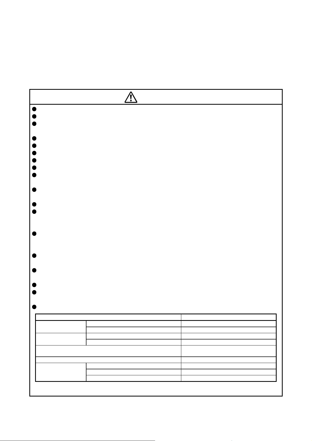
When you keep or use the equipment, please fulfill the following environment.
Item Environment
Ambient temperature
Storage -15 °C to 70 °C (non-freezing)
Ambient humidity
Storage 10 %RH to 90 %RH (non-condensing)
Altitude Max. 2000 m above sea level (Note)
HG-SN52/HG-SN102/HG-SN152 X, Y: 24.5 m/s2
Vibration resistance
HG-SN202/HG-SN302 X: 24.5 m/s2 Y: 49 m/s2
Note. Contact your local sales office for the altitude for options.
Ambience
Operation 0 °C to 40 °C (non-freezing)
Operation 10 %RH to 80 %RH (non-condensing)
Indoors (no direct sunlight), free from corrosive
gas, flammable gas, oil mist, dust, and dirt
HG-KN series X, Y: 49 m/s2
A - 3

(2) Wiring
CAUTION
Wire the equipment correctly and securely. Otherwise, the servo motor may operate unexpectedly.
Make sure to connect the cables and connectors by using the fixing screws and the locking mechanism.
Otherwise, the cables and connectors may be disconnected during operation.
Do not install a power capacitor, surge killer, or radio noise filter (optional FR-BIF) on the servo amplifier
output side.
To avoid a malfunction, connect the wires to the correct phase terminals (U/V/W) of the servo amplifier
and servo motor.
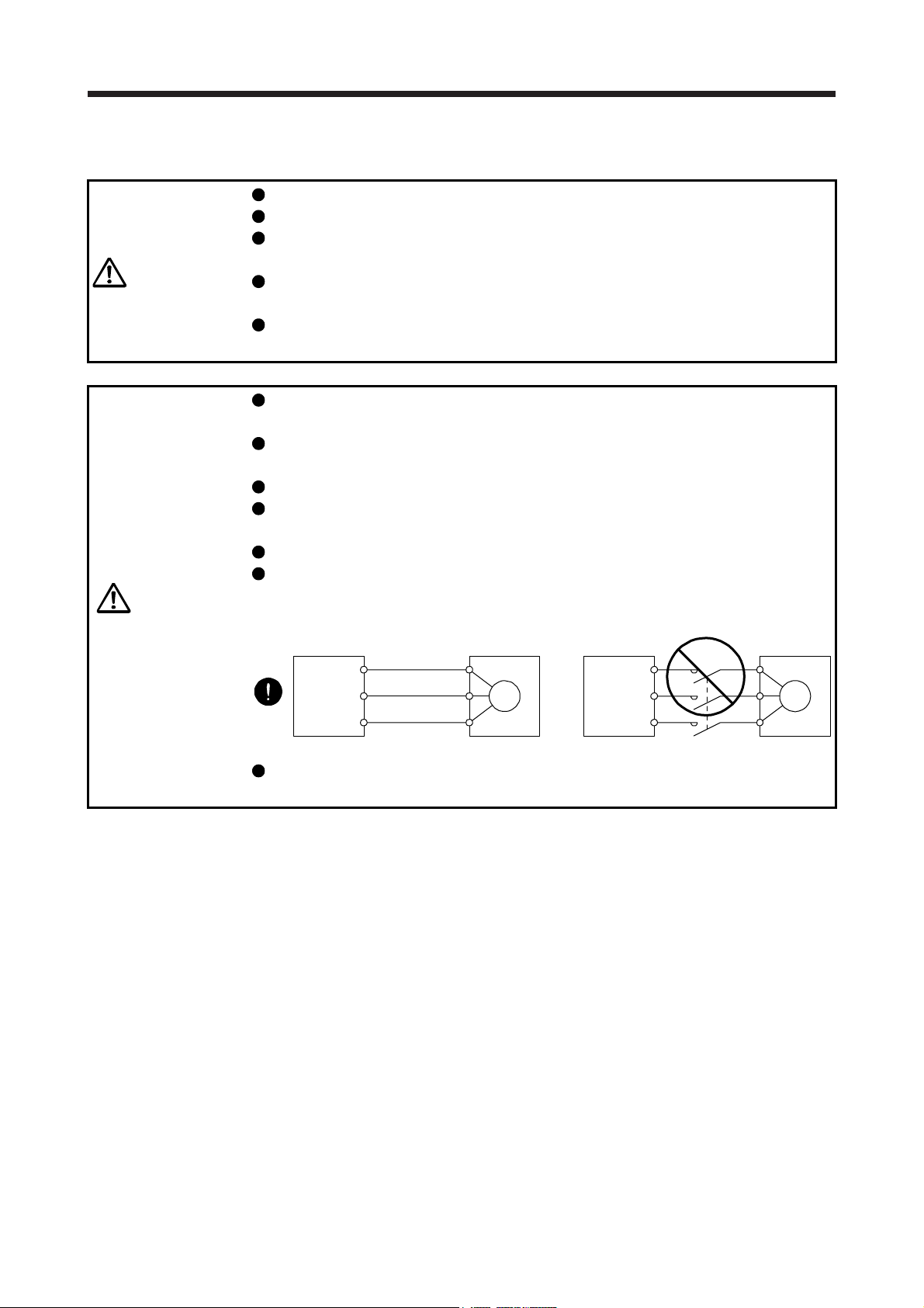
Connect the servo amplifier power output (U/V/W) to the servo motor power input (U/V/W) directly. Do
not let a magnetic contactor, etc. intervene. Otherwise, it may cause a malfunction.
Servo amplifier
U
V
W
Servo motor
U
V
W
Servo motorServo amplifier
U
M
V
W
U
V
W
M
Do not connect AC power supply directly to the servo motor. Otherwise, it may cause a malfunction.
When the cable is not tightened enough to the terminal block, the cable or terminal block may generate
heat because of the poor contact. Be sure to tighten the cable with specified torque.
(3) Test run and adjustment
CAUTION
Before operation, check the parameter settings. Improper settings may cause some machines to operate
unexpectedly.
Never make a drastic adjustment or change to the parameter values as doing so will make the operation
unstable.
A - 4
(4) Usage
CAUTION
When it is assumed that a hazardous condition may occur due to a power failure or product malfunction,
use a servo motor with an external brake to prevent the condition.
For equipment in which the moving part of the machine may collide against the load side, install a limit
switch or stopper to the end of the moving part. The machine may be damaged due to a collision.
Do not scratch the coated surface with hard objects nor clean the coated surface with an organic solvent.
Doing so may scuff the surface.
Do not disassemble, repair, or modify the product. Otherwise, an electric shock, fire, injury, etc. may
occur. Disassembled, repaired, and/or modified products are not covered under warranty.
Use the servo amplifier with the specified servo motor.
Correctly wire options and peripheral equipment, etc. in the correct combination. Otherwise, an electric
shock, fire, injury, etc. may occur.
The electromagnetic brake on the servo motor is designed to hold the motor shaft and should not be
used for ordinary braking.
For such reasons as incorrect wiring, service life, and mechanical structure (e.g. where a ball screw and
the servo motor are coupled via a timing belt), the electromagnetic brake may not hold the motor shaft.
To ensure safety, install a stopper on the machine side.
If the dynamic brake is activated at power-off, alarm occurrence, etc., do not rotate the servo motor by an
external force. Otherwise, it may cause a fire.
(5) Corrective actions
CAUTION
Ensure safety by confirming the power off, etc. before performing corrective actions. Otherwise, it may
cause an accident.
When it is assumed that a hazardous condition may occur due to a power failure or product malfunction,
use a servo motor with an electromagnetic brake or external brake to prevent the condition.
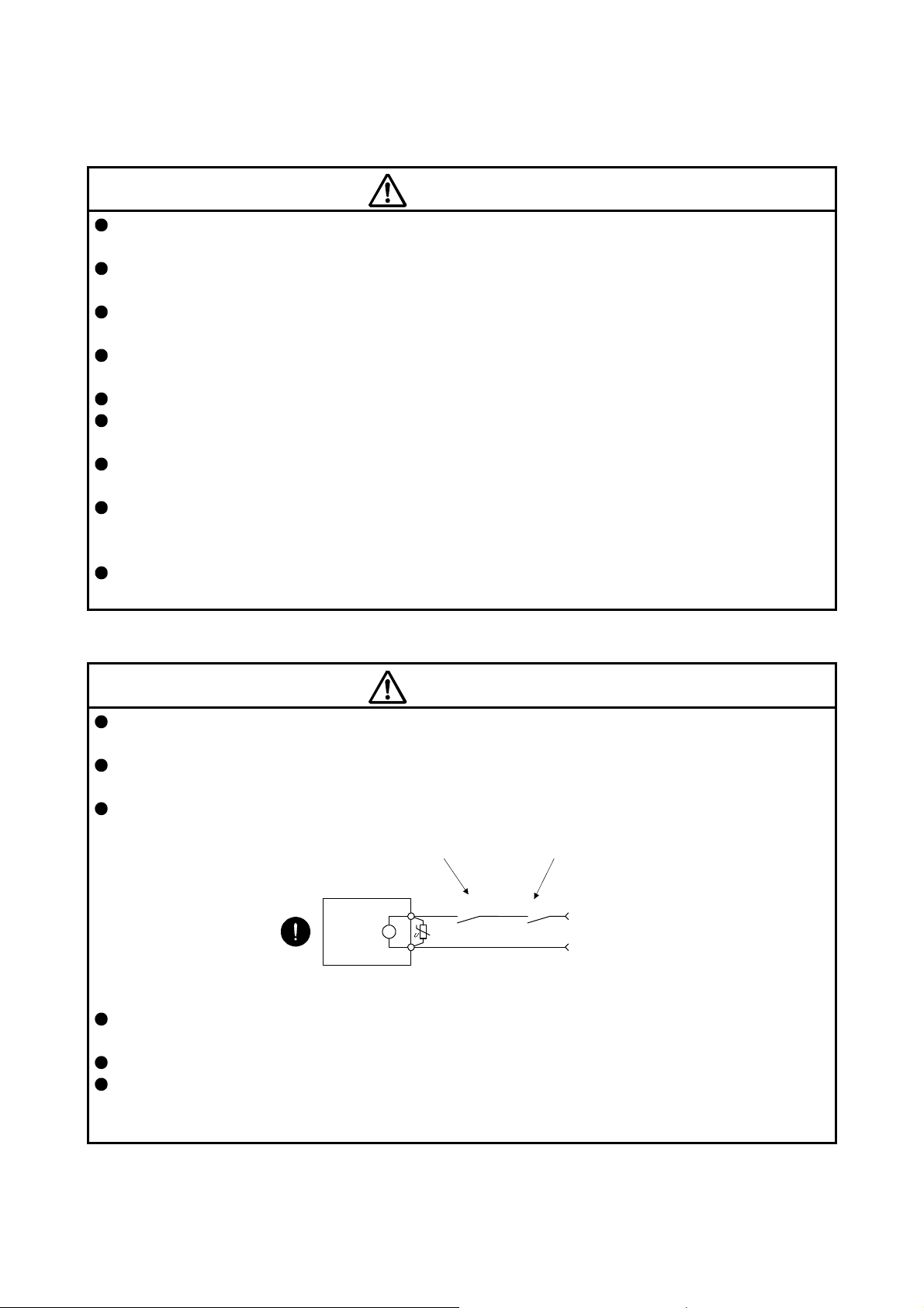
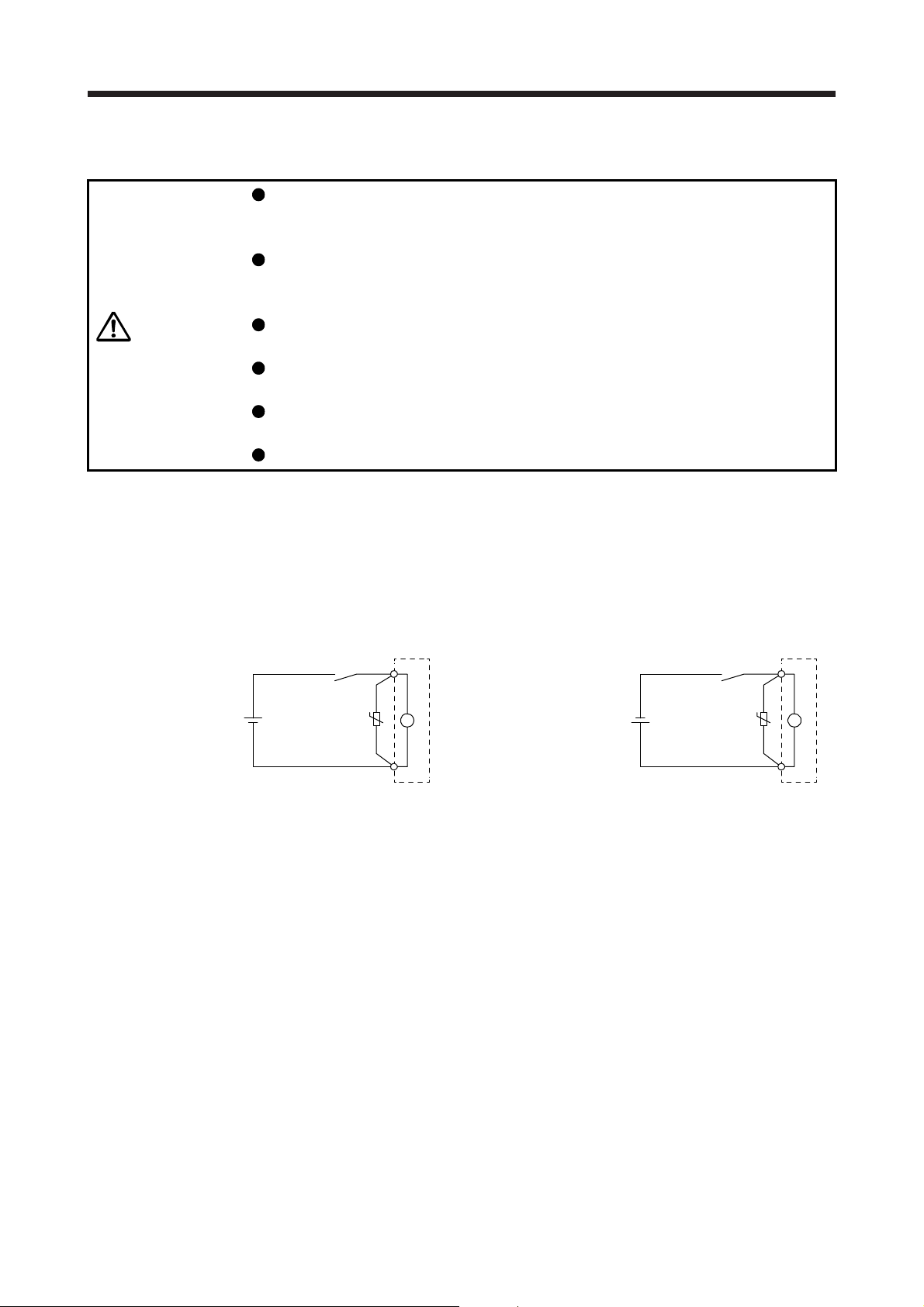
Configure an electromagnetic brake circuit which is interlocked with an external emergency stop switch.
Contacts must be opened when ALM
(Malfunction) or MBR (Electromagnetic
brake interlock) turns off.
Servo motor
B
Electromagnetic brake
When any alarm has occurred, eliminate its cause, ensure safety, and deactivate the alarm before
restarting operation.
Provide an adequate protection to prevent unexpected restart after an instantaneous power failure.
To prevent an electric shock, injury, or fire from occurring after an earthquake or other natural disasters,
ensure safety by checking conditions, such as the installation, mounting, wiring, and equipment before
switching the power on.
Contacts must be opened
with the emergency stop switch.
RA
24 V DC
A - 5
(6) Storage
CAUTION
Note the followings when storing the servo motor for an extended period of time (guideline: three or more
months).
Always store the servo motor indoors in a clean and dry place.
If it is stored in a dusty or damp place, make adequate provision, e.g. cover the whole product.
If the insulation resistance of the winding decreases, check how to store the equipment.
Though the motor is rust-proofed before shipment using paint or rust prevention oil, rust may be
produced depending on the storage conditions or storage period. If the servo motor is to be stored for
longer than six months, apply rust prevention oil again especially to the machined surfaces of the shaft,
etc.
Before using the product after storage for an extended period of time, hand-turn the servo motor output
shaft to confirm that nothing is wrong with the servo motor. When the servo motor is equipped with an
electromagnetic brake, check it after releasing the electromagnetic brake with the brake power supply.
When the product has been stored for an extended period of time, contact your local sales office.
(7) General instruction
To illustrate details, the equipment in the diagrams of this Instruction Manual may have been drawn
without covers and safety guards. When the equipment is operated, the covers and safety guards must
be installed as specified. Operation must be performed in accordance with this Instruction Manual.
DISPOSAL OF WASTE
Please dispose a servo motor and other options according to your local laws and regulations.
«Cables used for wiring»
Wires mentioned in this Instruction Manual are selected based on the ambient temperature of 40 ˚C.
«U.S. customary units»
U.S. customary units are not shown in this manual. Convert the values if necessary according to the
following table.
Mass 1 [kg] 2.2046 [lb]
Length 1 [mm] 0.03937 [inch]
Torque 1 [N•m] 141.6 [oz•inch]
Moment of inertia 1 [(× 10-4 kg•m2)] 5.4675 [oz•inch2]
Load (thrust load/axial load) 1 [N] 0.2248 [lbf]
Temperature N [°C] × 9/5 + 32 N [°F]
Quantity SI (metric) unit U.S. customary unit
A - 6
CONTENTS
1. INTRODUCTION 1- 1 to 1- 6
1.1 Rating plate ....................................................................................................................................... 1- 1
1.2 Parts identification ............................................................................................................................. 1- 2
1.3 Electromagnetic brake ...................................................................................................................... 1- 3
1.4 Servo motor shaft shapes ................................................................................................................. 1- 5
2. INSTALLATION 2- 1 to 2- 8
2.1 Mounting direction............................................................................................................................. 2- 2
2.2 Load mounting/dismounting precautions .......................................................................................... 2- 3
2.3 Permissible load for the shaft ........................................................................................................... 2- 4
2.4 Protection from oil and water ............................................................................................................ 2- 4
2.5 Cable ................................................................................................................................................. 2- 5
2.6 Servo motor with oil seal ................................................................................................................... 2- 5
2.7 Inspection items ................................................................................................................................ 2- 6
2.8 Parts having service life .................................................................................................................... 2- 6
2.9 Machine accuracies .......................................................................................................................... 2- 7
2.10 Mounting servo motors ................................................................................................................. 11- 7
2.11 Restrictions when using the equipment at altitudes exceeding 1000 m and up to 2000 m
above sea level ............................................................................................................................. 11- 7
3. CONNECTORS USED FOR SERVO MOTOR WIRING 3- 1 to 3- 6
3.1 Selection of connectors .................................................................................................................... 3- 1
3.2 Wiring connectors (connector configurations A/B/C) ........................................................................ 3- 2
3.3 Wiring connectors (connector configurations D/E/F/G) .................................................................... 3- 3
4. CONNECTION OF SERVO AMPLIFIER AND SERVO MOTOR 4- 1 to 4- 8
4.1 Connection instructions .................................................................................................................... 4- 2
4.2 Wiring ................................................................................................................................................ 4- 3
4.2.1 HG-KN series servo motor ......................................................................................................... 4- 3
4.2.2 HG-SN series servo motor ......................................................................................................... 4- 5
4.3 Selection example of wires ............................................................................................................... 4- 7
5. WIRING OPTION 5- 1 to 5-22
5.1 Cable/connector sets ........................................................................................................................ 5- 1
5.1.1 Combinations of cable/connector sets ....................................................................................... 5- 2
5.1.2 Cable and connector list ............................................................................................................. 5- 3
5.2 Encoder cable/connector sets .......................................................................................................... 5- 6
5.3 Servo motor power cable ................................................................................................................. 5-17
5.4 Electromagnetic brake cable ........................................................................................................... 5-19
5.5 Wires for option cables .................................................................................................................... 5-20
6. HG-KN SERIES 6- 1 to 6-18
6.1 Model designation ............................................................................................................................. 6- 1
6.2 Combination list of servo motors and servo amplifiers ..................................................................... 6- 1
1
6.3 Standard specifications ..................................................................................................................... 6- 2
6.3.1 Standard specifications list......................................................................................................... 6- 2
6.3.2 Torque characteristics ................................................................................................................ 6- 4
6.4 Electromagnetic brake characteristics .............................................................................................. 6- 5
6.5 Servo motors with special shafts ...................................................................................................... 6- 6
6.5.1 Key shaft (with 2 round end key) ............................................................................................... 6- 6
6.5.2 D cut shaft .................................................................................................................................. 6- 6
6.6 Servo motor with oil seal ................................................................................................................... 6- 7
6.7 Mounting connectors ........................................................................................................................ 6- 8
6.8 Dimensions ....................................................................................................................................... 6- 9
6.8.1 Standard (without an electromagnetic brake) ............................................................................ 6- 9
6.8.2 With an electromagnetic brake ................................................................................................. 6-13
7. HG-SN SERIES 7- 1 to 7-12
7.1 Model designation ............................................................................................................................. 7- 1
7.2 Combination list of servo motors and servo amplifiers ..................................................................... 7- 1
7.3 Standard specifications ..................................................................................................................... 7- 2
7.3.1 Standard specifications list......................................................................................................... 7- 2
7.3.2 Torque characteristics ................................................................................................................ 7- 4
7.4 Electromagnetic brake characteristics .............................................................................................. 7- 5
7.5 Servo motors with special shafts ...................................................................................................... 7- 6
7.6 Servo motor with oil seal ................................................................................................................... 7- 6
7.7 Dimensions ....................................................................................................................................... 7- 7
7.7.1 Standard (without an electromagnetic brake) ............................................................................ 7- 7
7.7.2 With an electromagnetic brake .................................................................................................. 7- 9
APPENDIX App.- 1 to App.-10
App. 1 Servo motor ID codes ........................................................................................................... App.- 1
App. 2 Manufacturer list .................................................................................................................... App.- 1
App. 3 Compliance with the CE marking .......................................................................................... App.- 2
App. 4 Compliance with UL/CSA standard ....................................................................................... App.- 3
App. 5 Selection example of servo motor power cable .................................................................... App.- 4
App. 6 Connector dimensions .......................................................................................................... App.- 5
2
1. INTRODUCTION
1. INTRODUCTION
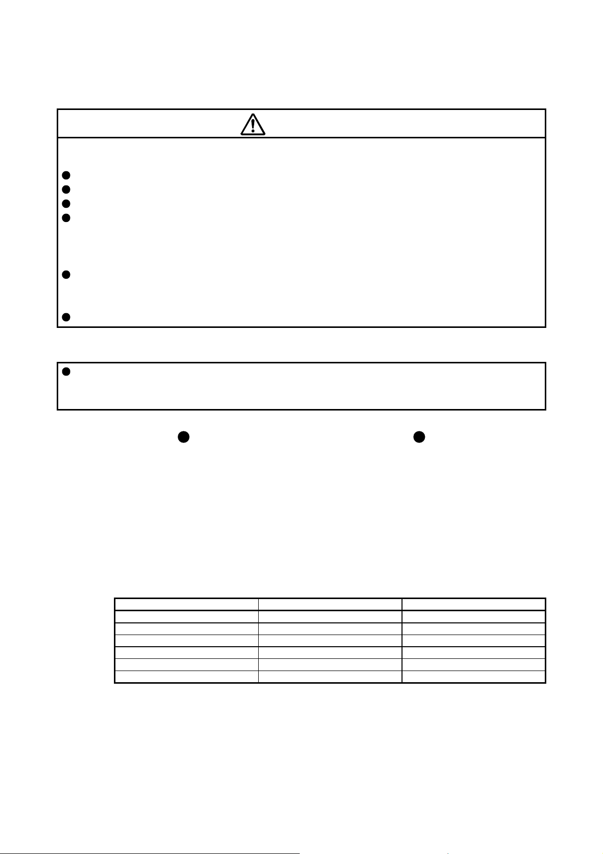
1.1 Rating plate
The following shows an example of rating plate for explanation of each item.
Model
Input power, rated current and rated output
Mass and insulation class
Rated speed
Induced voltage constant and maximum ambient temperature
Power factor and IP rating
Serial number (Note 1)
Country of origin and conforming standards
Manufacturer
0.57
31
MADE IN JAPAN
FABRIQUÉ AU JA PON
HG-KN13J
112 0.8
98
100W
(Note 2)
MSIP-REI-MEK-BSM0060000000A
Note 1. Production year and month of the servo motor are indicated in a serial number on the rating plate.
The year and month are indicated by the last two digits of the year and one digit of the month [1 to 9, X (10),
Y (11), and Z (12)].
For January 2012, the Serial No. is like, "SER. _ _ _ _ _ _ _ _ _ 121".
2. Products approved by Certification Bodies are marked. The marks depends on the Certification Bodies.
1 - 1
1. INTRODUCTION
A
)
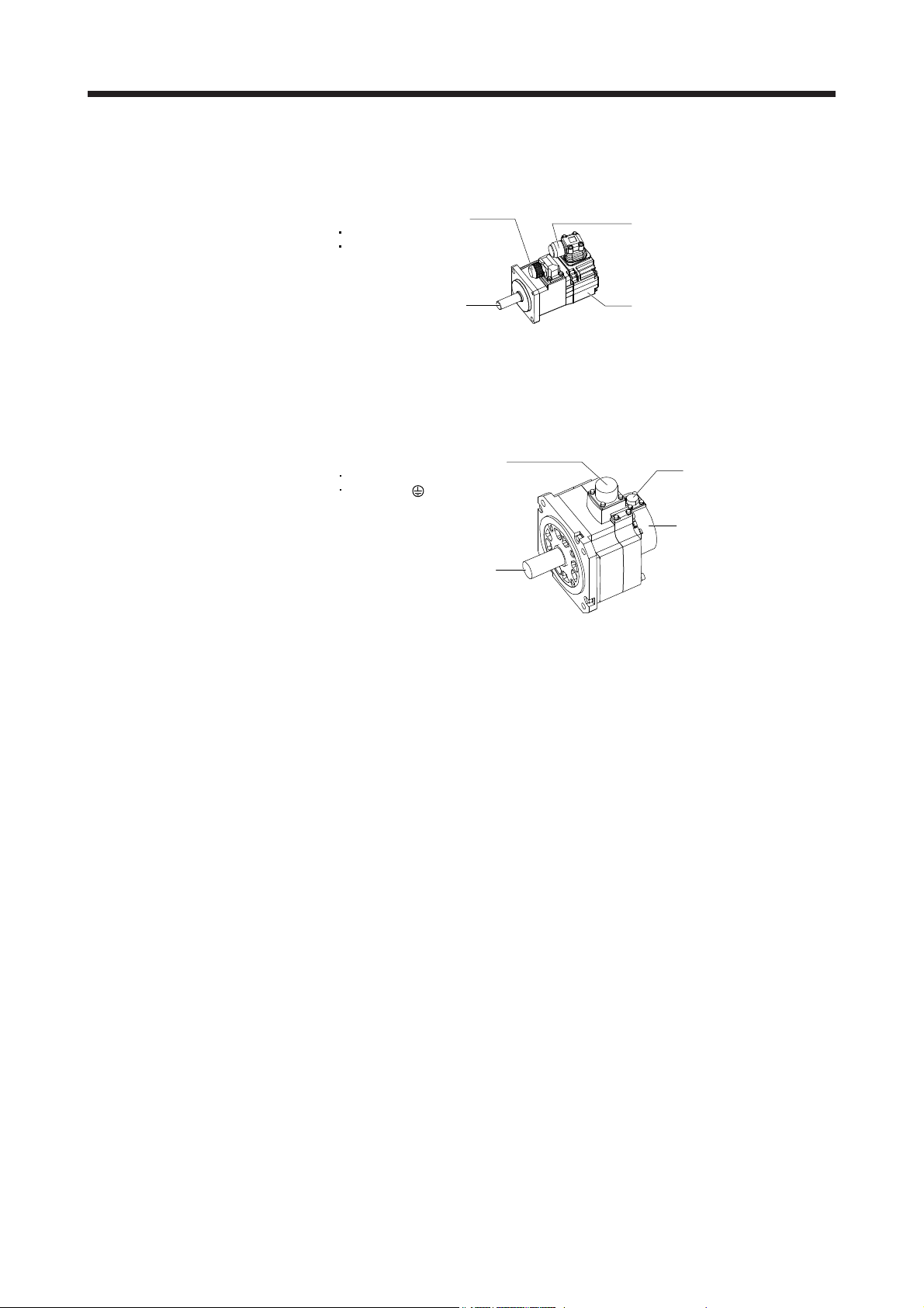
1.2 Parts identification
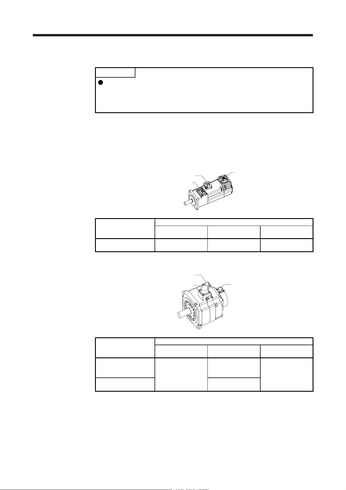
(1) HG-KN series servo motor
Power cable (Note 1, 2)
Power lead (U/V/W)
Grounding lead
Encoder cable (Note 1)
(2) HG-SN series servo motor
Servo motor shaft
Note 1. The encoder cable and power supply cable are options.
2.
Power supply connector (Note
Power supply (U/V/W)
Grounding ( )
Note. The servo motor with an electromagnetic brake has the electromagnetic brake
n electromagnetic brake cable is separately required for the servo motor with an
electromagnetic brake.
Servo motor shaft
connector separately.
Encoder
Encoder connector
Encoder
1 - 2
1. INTRODUCTION
1.3 Electromagnetic brake
The electromagnetic brake is provided to prevent a drop at a power failure or
alarm occurrence during vertical drive or to hold a shaft at a stop. Do not use it for
normal braking (including braking at servo-lock).
The electromagnetic brake has a time lag. Ensure enough time between releasing
the electromagnetic brake and starting the servo motor. Be sure to check the
operation delay time with an actual machine.
Configure an electromagnetic brake circuit so that it is activated also by an
CAUTION
The servo motor with an electromagnetic brake can be used to prevent a drop in vertical lift applications or to
ensure double safety at an emergency stop, for example. When operating the servo motor, supply power to
the electromagnetic brake to release the brake. Switching power off enables the electromagnetic brake.
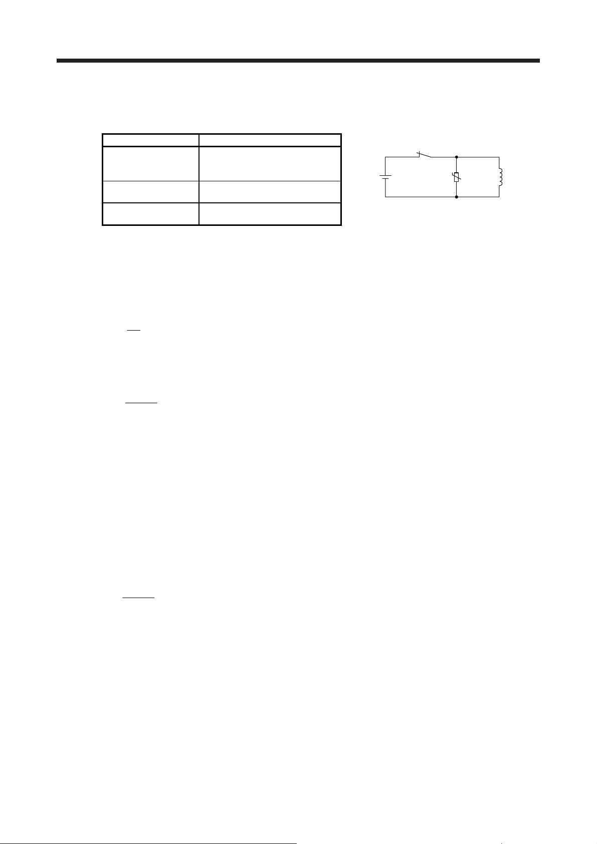
(1) Electromagnetic brake power supply
Prepare the following power supply for use with the electromagnetic brake only. The electromagnetic
brake terminals (B1/B2) have no polarity.
external emergency stop switch.
For details of the circuit configuration and timing chart, refer to each servo
amplifier instruction manual.
While the electromagnetic brake is opened, the motor may be raised to high
temperature regardless of driving.
The life will be shortened under sudden acceleration/deceleration conditions.
B1
B1
24 V DC
power supply for
electromagnetic brake
Switch
VAR
B
U
B2
Electromagnetic brake
24 V DC
or
power supply for
electromagnetic brake
Switch
VAR
U
The surge absorber (VAR) must be installed between B1 and B2. For a selection example of the surge
absorber, refer to "Electromagnetic brake characteristic" in the chapter of each servo motor series.
When you use a diode for a surge absorber, the electromagnetic braking time will be longer.
(2) Sound generation
Though the brake lining may rattle during operation, it poses no functional problem.
If braking sounds, it may be improved by setting the machine resonance suppression filter in the servo
amplifier parameters. For details, refer to each servo amplifier instruction manual.
B2
B
Electromagnetic brake
1 - 3
1. INTRODUCTION
(3) Selection of surge absorbers for electromagnetic brake circuit
The following shows an example how to select a varistor with a surge absorber.
(a) Selection conditions
Electromagnetic brake
specification
Desired suppression
voltage
Durable surge
application time
(b) Tentative selection and verification of surge absorber
1) Maximum allowable circuit voltage of varistor
Tentatively select a varistor whose maximum allowable voltage is larger than Vb [V].
2) Brake current (Ib)
Ib =
3) Energy (E) generated by brake coil
E =
4) Varistor limit voltage (Vi)
From the energy (E) generated in the brake coil and the varistor characteristic diagram, calculate
the varistor limit voltage (Vi) when the brake current (Ib) flows into the tentatively selected varistor
during opening of the circuit.
Vi is favorable when the varistor limit voltage (Vi) [V] is smaller than the desired suppressed
voltage (Vs) [V].
If Vi is not smaller than Vs, reselect a varistor or improve the withstand voltage of devices.
5) Surge current width (τ)
Given that the varistor absorbs all energies, the surge current width (τ) will be as follows.
τ =
6) Examining surge life of varistor
From the varistor characteristic diagram, find the guaranteed current value (Ip) in which the
number of the surge application life is N at the surge current width (τ). Calculate the guaranteed
current value (Ip) ratio to brake current (Ib).
If an enough margin is ensured for Ip/Ib, the number of the surge application life N [time] can be
considered as favorable.
(4) Others
A leakage magnetic flux will occur at the shaft end of the servo motor equipped with an electromagnetic
brake. Note that chips, screws, etc. are attracted.
Item Condition
R [Ω]: Resistance
L [H]: Inductance
Vb [V]: Power supply voltage
Vs [V] or less
N times
Vb
[A]
R
2
L × lb
[J]
2
E
Vi × lb
[S]
Relay
24 V DC
U
Varistor
Brake coil
1 - 4
1. INTRODUCTION
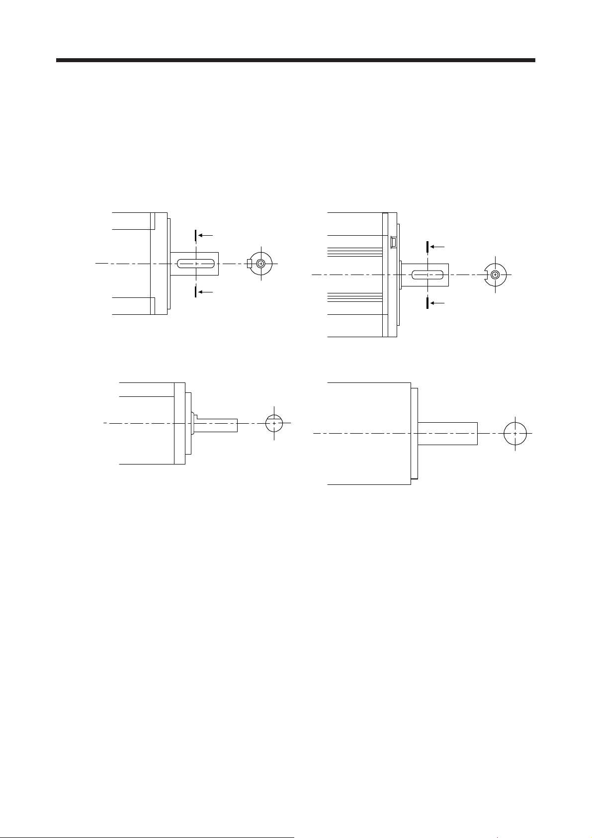
1.4 Servo motor shaft shapes
In addition to the straight shaft, the key shaft and D cut shaft are available.
The key shaft and D cut shaft cannot be used in very frequent start/stop applications.
Since we cannot warrant the servo motor against fracture and similar accidents attributable to a loose key,
use a friction coupling, etc. when coupling the shaft with a machine.
The shaft shape of the standard servo motor changes depending on the series and capacity. Refer to the
chapter of the servo motor series.
A
A
A
Shaft section view AA
A
Shaft section view AA
Key shaft (with 2 round end key) Key shaft (without key)
D cut shaft Straight shaft
1 - 5
1. INTRODUCTION
MEMO
1 - 6
2. INSTALLATION
2. INSTALLATION
WARNING
CAUTION
To prevent electric shock, ground each equipment securely.
Stacking in excess of the specified number of product packages is not allowed.
Install the equipment on incombustible material. Installing them directly or close to
combustibles will lead to smoke or a fire.
Install the servo motor in a load-bearing place in accordance with the Instruction
Manual.
Do not get on or put heavy load on the equipment. Otherwise, it may cause injury.
Use the equipment within the specified environment. For the environment, refer to
the specifications of the servo motor series.
Do not drop or strike the servo motor. Isolate it from all impact loads.
Do not install or operate a faulty servo motor.
Do not carry the servo motor by holding the cables, connectors, shaft, or encoder.
Otherwise, it may drop.
Securely fix the servo motor to the machine. If being attached insecurely, the
motor may come off during operation, leading to injury.
Be sure to measure the vibration level with the servo motor mounted on the
machine when checking the vibration level. A great vibration may cause the early
damage to a bearing, encoder, and brake. The great vibration may also cause the
poor connector connection or bolt looseness.
For the gain adjustment at the equipment startup, check the torque waveform and
the speed waveform with a measurement device to check that no vibration
occurs. If the vibration occurs due to high gain, the vibration may cause the early
damage to the servo motor.
Never hit the servo motor or shaft, especially when coupling the servo motor to
the machine. Otherwise, the encoder may malfunction.
When coupling a load to the servo motor, do not use a rigid coupling. Doing so
can cause the shaft to break and the bearing to wear out.
Balance the load to the extent possible. Not doing so can cause vibration during
servo motor operation or damage the bearings and encoder.
Take safety measures, e.g. provide covers, to prevent accidental access to the
rotor of the servo motor during operation.
Do not subject the servo motor shaft to more than the permissible load.
Otherwise, the shaft may break, leading to injury.
When the product has been stored for an extended period of time, contact your
local sales office.
When handling the servo motor, be careful with the sharp edges of the servo
motor, shaft keyway, or others.
Do not use the servo motor where the shaft-through portion may be subject to
pressure (e.g. compressed air). Applying air pressure to the inside of the servo
motor may cause a malfunction.
2 - 1
2. INSTALLATION
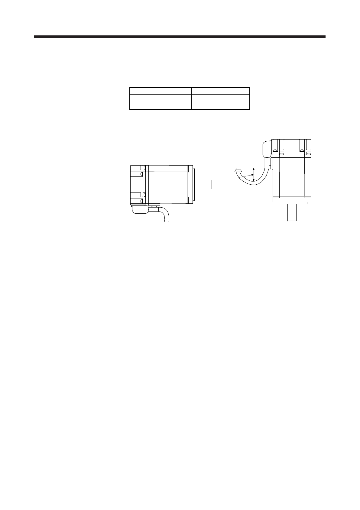
2.1 Mounting direction
(1) Standard servo motor
The following table indicates the mounting direction of the standard servo motor.
For mounting in the horizontal direction, it is recommended to set the connector section downward.
When mounting the motor vertically or obliquely, give a little slack for the connection cable.
Servo motor series Mounting direction
HG-KN
HG-SN
All direction
Little slack
(2) Servo motor with an electromagnetic brake
The servo motor with an electromagnetic brake can also be installed in the same orientation as the
standard servo motor. When the servo motor with an electromagnetic brake is installed with the shaft
end at top, the brake plate may generate sliding sound but it is not a fault.
2 - 2
2. INSTALLATION
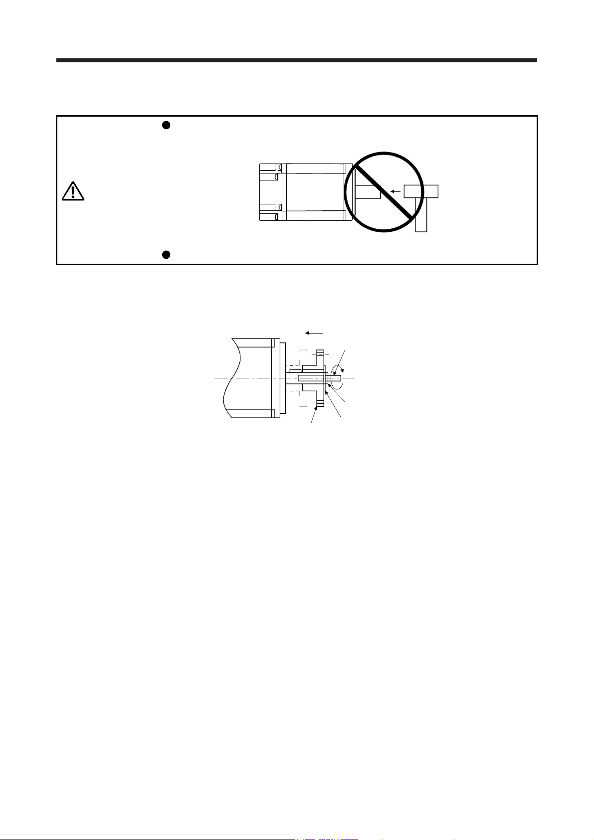
2.2 Load mounting/dismounting precautions
During assembling, the shaft end must not be hammered. Otherwise, the encoder
may malfunction.
CAUTION
Do not process the shaft to avoid damage to the encoder and bearing.
(1) When mounting a pulley to the servo motor with a key shaft, use the screw hole in the shaft end. To fit
the pulley, first insert a double-end stud into the screw hole of the shaft, put a washer against the end
face of the coupling, and insert and tighten a nut to force the pulley in.
Servo motor
Double-end stud
Nut
Pulley
Washer
(2) For the shaft without a key, use a friction coupling or the like.
(3) When removing the pulley, use a pulley remover to protect the shaft from hard load and or impact.
(4) To ensure safety, fit a protective cover or the like on the rotary area, such as the pulley, mounted to the
shaft.
(5) When a threaded shaft end part is needed to mount a pulley on the shaft, please contact your local sales
office.
(6) The direction of the encoder on the servo motor cannot be changed.
(7) When mounting the servo motor, use spring washers, etc. and fully tighten the bolts so that they do not
become loose due to vibration.
2 - 3
2. INSTALLATION
2.3 Permissible load for the shaft
CAUTION
For the permissible shaft load specific to the servo motor, refer to the chapter of the servo motor series.
(1) Use a flexible coupling and adjust the misalignment of the shaft to less than the permissible radial load.
(2) When using a pulley, sprocket, or timing belt, keep the radial load within the permissible value.
(3) Excess of the permissible load can cause the bearing life to reduce and the shaft to break.
(4) The load indicated in this section is static load in a single direction and does not include eccentric load.
Make eccentric load as small as possible. Not doing so can cause the servo motor to be damaged.
2.4 Protection from oil and water
Do not use a rigid coupling as it may apply excessive bending load to the shaft of
the servo motor, leading the shaft to break and the bearing to wear out.
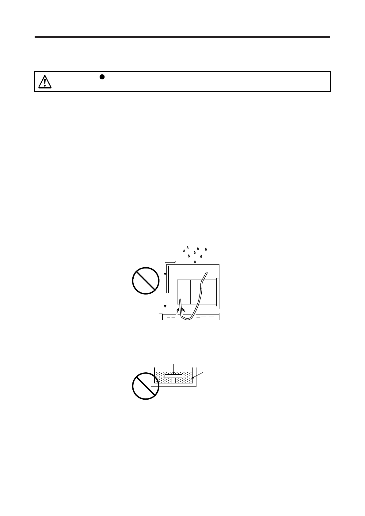
Provide adequate protection to prevent foreign matter, such as oil from entering the servo motor shaft. When
installing the servo motor, consider the items in this section.
(1) Do not use the direct drive motor with its cable soaked in oil or water.
Cover
Servo
motor
Oil/water pool
Capillary action
(2) When the servo motor is to be installed with the shaft end at top, provide measures so that it is not
exposed to oil and water entering from the machine side, gear box, etc.
Gear
Lubricating oil
Servo motor
(3) If oil such as cutting oil drops on the servo motor, the sealant, packing, cable and others may be affected
depending on the oil type.
(4) In the environment where the servo motor is exposed to oil mist, oil, water, grease and/or like, a
standard specifications servo motor may not be usable. Please contact your local sales office.
2 - 4

2. INSTALLATION
2.5 Cable
The power supply and encoder cables routed from the servo motor should be fixed to the servo motor to
keep them unmovable. Otherwise, the cable may disconnect. In addition, do not modify the connectors,
terminals and others at the ends of the cables.
2.6 Servo motor with oil seal
For the servo motor with oil seal, the oil seal prevents the entry of oil into the servo motor. Make sure to
install it according in this section.
The functions have no problem even if the servo motor with oil seal may sound during operation.
(1) Pressure and oil level
Install the servo motor horizontally, and set the oil level in the gear box to be lower than the oil seal lip
always. If the oil level is higher than the oil seal lip, the oil enter the servo motor and may cause a
malfunction. Refer to the chapter of the servo motor series for the height above oil level.
Shaft
Gear
Servo motor
Height above oil level h
Lip
Oil seal
High pressure against the oil seal causes the abrasion and makes the life be short. Keep constant
internal pressure by equipping a ventilator to the gear box.
(2) Temperature
High temperature against the oil seal lip makes the life be short. Avoid exposing the oil seal lip to high
temperature oil since applicable temperature of the material is up to 100 °C and temperature of the oil
seal lip rises within 10 °C to 15 °C at maximum rotation.
2 - 5
2. INSTALLATION
2.7 Inspection items
Before starting maintenance and/or inspection, turn off the power and wait for 15
minutes or more until the charge lamp turns off. Otherwise, an electric shock may
WARNING
CAUTION
It is recommended that the following points periodically be checked.
(1) Check the bearings, brake section, etc. for unusual noise.
(2) Check the cables and the like for scratches or cracks. Especially when the cable is movable, perform
periodic inspections according to operating conditions.
(3) Check the servo motor shaft and coupling for misalignment.
(4) Check the power connector and encoder connector tightening screws for looseness.
2.8 Parts having service life
occur. In addition, when confirming whether the charge lamp is off or not, always
confirm it from the front of the servo amplifier.
To avoid an electric shock, only qualified personnel should attempt inspections.
For repair and parts replacement, contact your local sales office.
Do not perform insulation resistance test on the servo motor. Otherwise, it may
cause a malfunction.
Do not disassemble and/or repair the equipment on customer side.
Service life of the following parts is listed below. However, the service life varies depending on operating
methods and environment. If any fault is found in the parts, they must be replaced immediately regardless of
their service life. For parts replacement, please contact your local sales office.
Part name Life guideline
Bearings
Encoder
Oil seal 5000 hours
20,000 hours to
30,000 hours
20,000 hours to
30,000 hours
(1) Bearings
When the motor is run at rated speed under rated load, bearings should be exchanged in 20,000 to
30,000 hours as a guideline. This differs on the operating conditions. The bearings must also be
changed if unusual noise or vibration is found during inspection.
(2) Oil seal
Oil seals must be changed in 5,000 hours of operation at rated speed as a guideline. They must also be
changed if oil leakage, etc. is found during inspection.
The functions have no problem even if an oil seal may sound during operation.
2 - 6
2. INSTALLATION
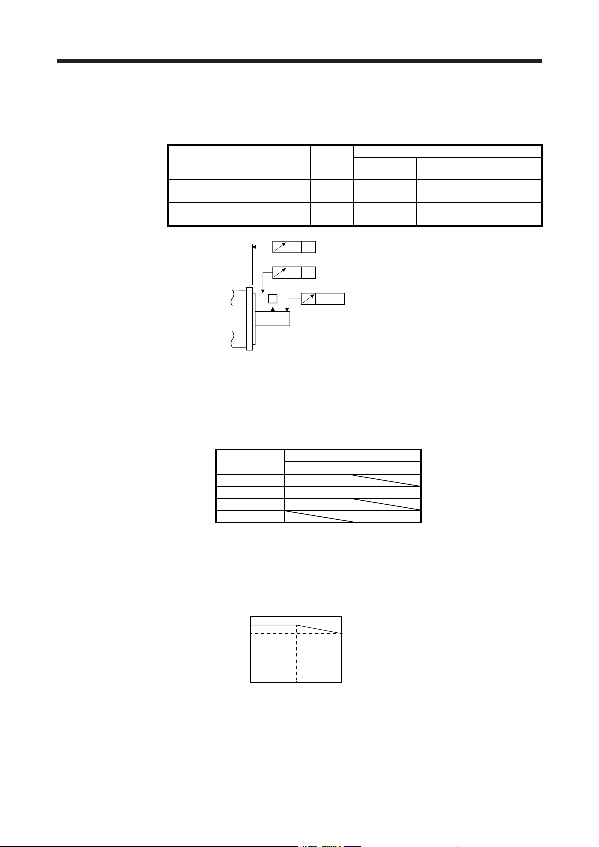
2.9 Machine accuracies
The following table indicates the machine accuracies of the servo motor around the output shaft and
mounting. (except the optional products)
Accuracy [mm]
Runout of flange surface to output
shaft
Runout of fitting OD of flange surface b) 0.04 0.04 0.06
Runout of output shaft end c) 0.02 0.02 0.03
Measuring
position
a) 0.05 0.06 0.08
100 × 100
or less
a)
A
b)
A
A
c)
Flange size
130 × 130 176 × 176
2.10 Mounting servo motors
Be sure to use the servo motor within the specified environment, and mount the servo motor on a machine
having the equivalent heat dissipation effect as the following aluminum flange.
The temperature of the servo motor increases differently depending on its mounting environment, operating
conditions, etc. Make sure to check the temperature with an actual machine.
Flange size [mm]
250 × 250 × 6 13/23
250 × 250 × 12 43 52/102/152
300 × 300 × 12 73
300 × 300 × 20 202/302
Servo motor
HG-KN HG-SN
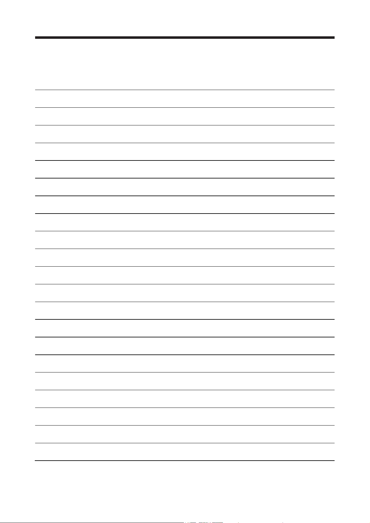
2.11 Restrictions when using the equipment at altitudes exceeding 1000 m and up to 2000 m above sea level
As heat dissipation effects decrease in proportion to decreasing air density, use the equipment within the
effective load ratio and regenerative load ratio shown in the following figure.
[%]
100
95
Effective load ratio
0
0
Regenerative load ratio
Altitude
[m]
20001000
2 - 7
2. INSTALLATION
MEMO
2 - 8
3. CONNECTORS USED FOR SERVO MOTOR WIRING
r
3. CONNECTORS USED FOR SERVO MOTOR WIRING
POINT
The IP rating indicated is the connector's protection against ingress of dust and
water when the connector is connected to a servo motor. If the IP rating of the
connector, and servo motor vary, the overall IP rating depends on the lowest IP
rating of all components.
3.1 Selection of connectors
Use the connector configuration products given in the table as the connectors for connection with the servo
motor. Refer to section 3.2 and 3.3 for the compatible connector configuration products.
(1) HG-KN series
Electromagnetic brake connector
Power supply connector
Encoder connector
Wiring connector
Servo motor
HG-KN_
For encoder For power supply
Connector
configuration A
Connector
configuration B
For electromagnetic
brake
Connector
configuration C
(2) HG-SN series
Electromagnetic brake connecto
Power supply connector
Encoder connector
Wiring connector
Servo motor
HG-SN52
HG-SN102
HG-SN152
HG-SN202
HG-SN302
For encoder For power supply
Connector
Connector
configuration D
configuration E
Connector
configuration G
For electromagnetic
brake
Connector
configuration F
3 - 1
3. CONNECTORS USED FOR SERVO MOTOR WIRING
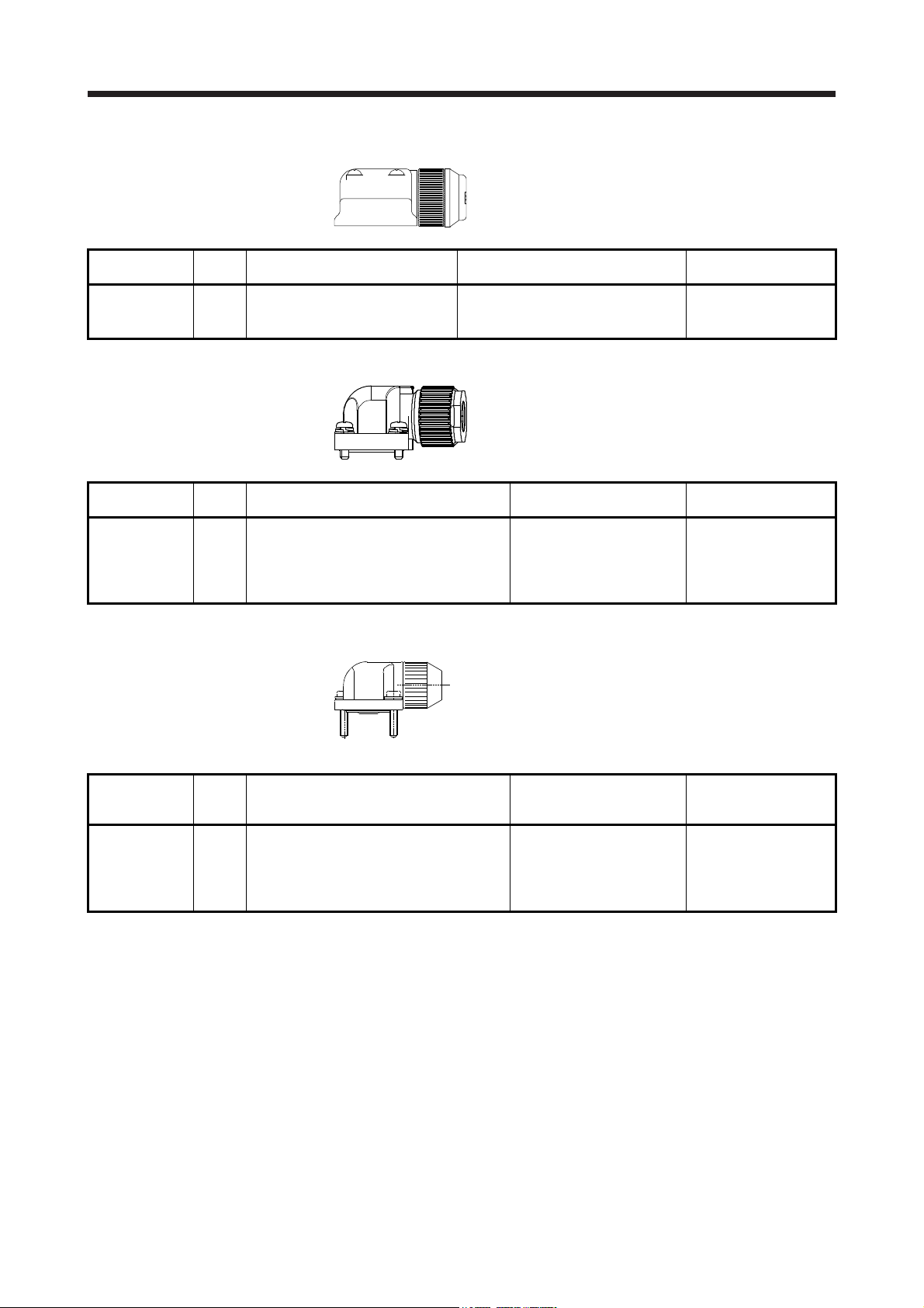
3.2 Wiring connectors (connector configurations A/B/C)
Connector
configuration
A
(for encoder)
Feature Connector Crimping tool
Connector: 2174053-1
IP65
(TE Connectivity)
Note. The connector to be mated.
Connector
configuration
B
(for power
supply)
Feature Connector Crimping tool
Connector: KN4FT04SJ1-R
HOOD/SOCKET
INSULATOR/BUSHING/GROUND NUT
IP65
Contact: ST-TMH-S-C1B-100 (A534G)
(JAE)
Note. The connector to be mated.
For ground clip: 1596970-1
For receptacle contact: 1596847-1
(TE Connectivity)
CT170-14-TMH5B
(JAE)
Servo motor encoder
connector (Note)
1674339-1
(TE Connectivity)
Servo motor power
connector (Note)
JN4AT04NJ1
(JAE)
Connector
configuration
C
(for
electromagnetic
brake)
Feature Connector Crimping tool
Connector: JN4FT02SJ1-R
HOOD/SOCKET
INSULATOR/BUSHING/GROUND NUT
IP65
Contact: ST-TMH-S-C1B-100 (A534G)
(JAE)
Note. The connector to be mated.
CT170-14-TMH5B
(JAE)
Servo motor
electromagnetic brake
connector (Note)
JN4AT02PJ1
(JAE)
3 - 2
3. CONNECTORS USED FOR SERVO MOTOR WIRING
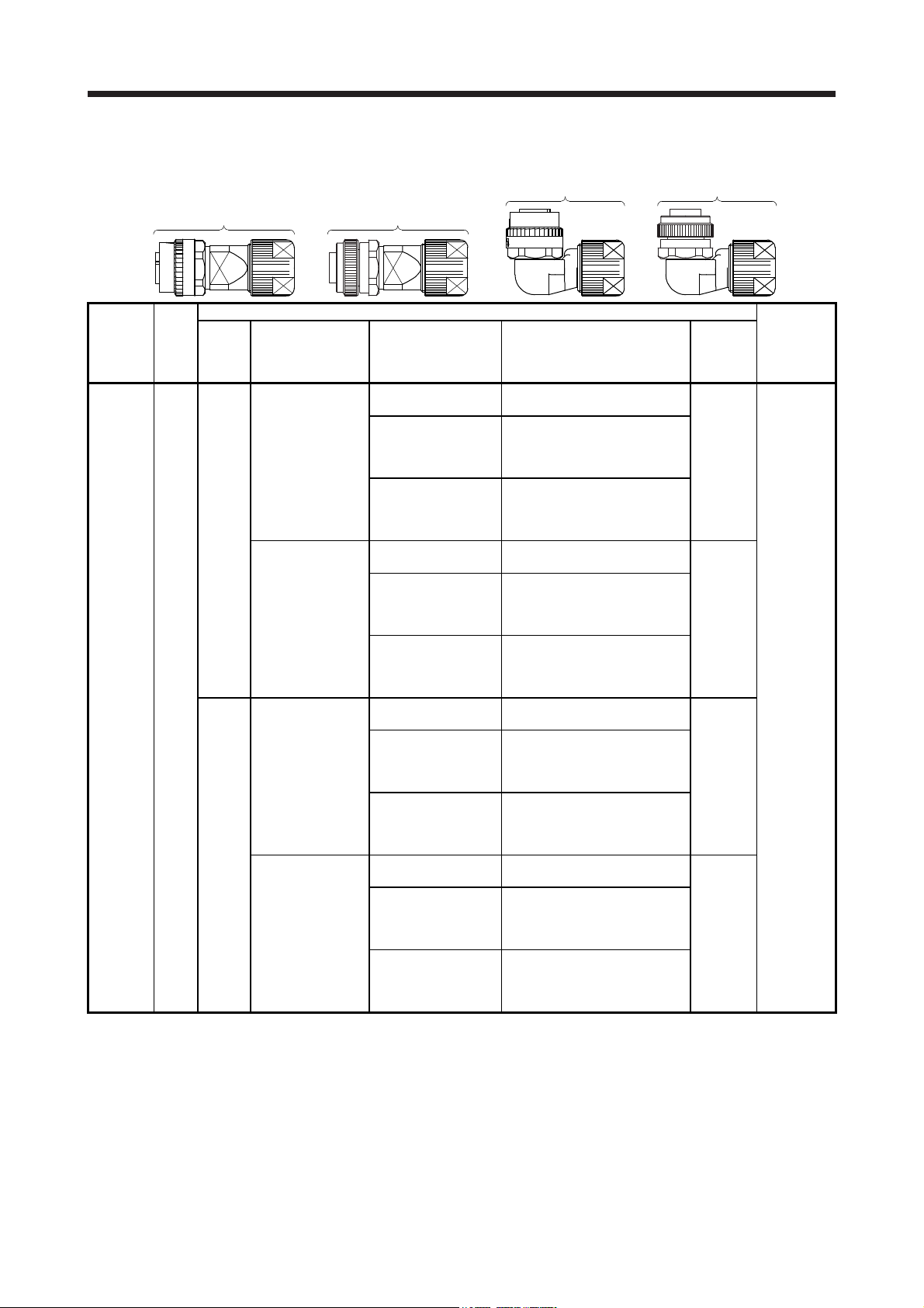
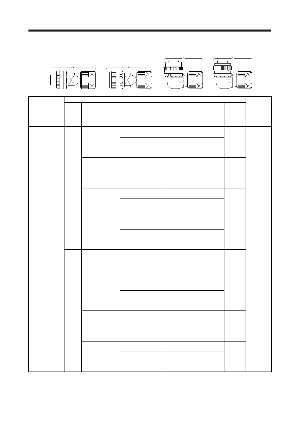
3.3 Wiring connectors (connector configurations D/E/F/G)
Angle plug
Straight plug
(one-touch connection type)
Straight plug
(screw type)
(one-touch connection type)
Angle plug
(screw type)
Connector
configuration
(for encoder)
Feature
D
IP67
Type Plug Socket contact Contact shape
CMV1-SP10S-M1
(one-touch connection
type)
CMV1S-SP10S-M1
(screw type)
Straight
CMV1-SP10S-M2
(one-touch connection
type)
CMV1S-SP10S-M2
(screw type)
CMV1-AP10S-M1
(one-touch connection
type)
CMV1S-AP10S-M1
(screw type)
Angle
CMV1-AP10S-M2
(one-touch connection
type)
CMV1S-AP10S-M2
(screw type)
Note. The connector to be mated.
Plug (DDK)
CMV1-#22ASC-S1-100
CMV1-#22ASC-C1-100
CMV1-#22ASC-C2-100
CMV1-#22ASC-S1-100
CMV1-#22ASC-C1-100
CMV1-#22ASC-C2-100
CMV1-#22ASC-S1-100
CMV1-#22ASC-C1-100
CMV1-#22ASC-C2-100
CMV1-#22ASC-S1-100
CMV1-#22ASC-C1-100
CMV1-#22ASC-C2-100
Soldering type
Applicable wire size: AWG 20 or less
Crimping type
Applicable wire size: AWG 24 to 20
The crimping tool (357J-53162T)
is required.
Crimping type
Applicable wire size: AWG 28 to 24
The crimping tool (357J-53163T)
is required.
Soldering type
Applicable wire size: AWG 20 or less
Crimping type
Applicable wire size: AWG 24 to 20
The crimping tool (357J-53162T)
is required.
Crimping type
Applicable wire size: AWG 28 to 24
The crimping tool (357J-53163T)
is required.
Soldering type
Applicable wire size: AWG 20 or less
Crimping type
Applicable wire size: AWG 24 to 20
The crimping tool (357J-53162T)
is required.
Crimping type
Applicable wire size: AWG 28 to 24
The crimping tool (357J-53163T)
is required.
Soldering type
Applicable wire size: AWG 20 or less
Crimping type
Applicable wire size: AWG 24 to 20
The crimping tool (357J-53162T)
is required.
Crimping type
Applicable wire size: AWG 28 to 24
The crimping tool (357J-53163T)
is required.
Cable
OD
[mm]
(reference)
5.5 to 7.5
7.0 to 9.0
5.5 to 7.5
7.0 to 9.0
Servo motor
encoder
connector
(Note)
CMV1-R10P
3 - 3
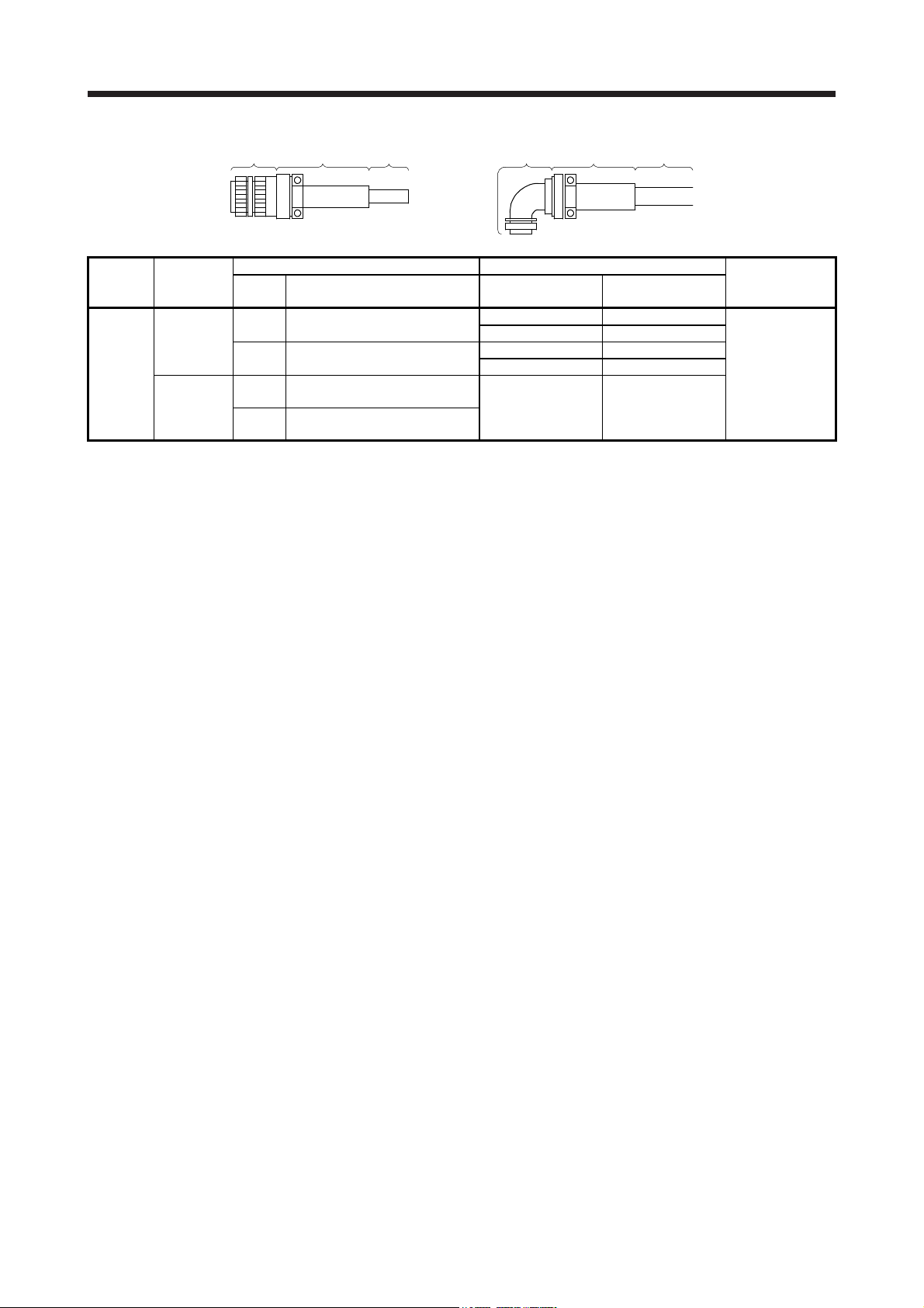
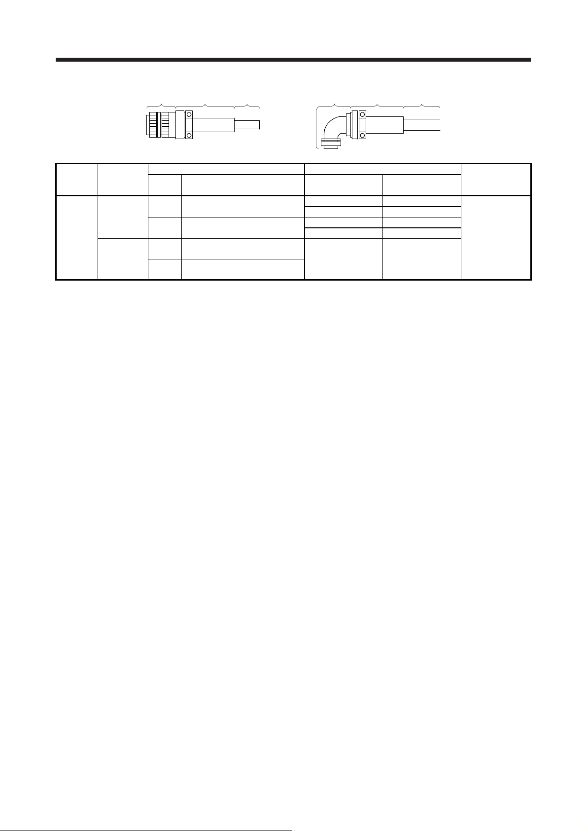
3. CONNECTORS USED FOR SERVO MOTOR WIRING
Plug Cable clamp Cable Plug Cable clamp Cable
Connector
configuration
E
(for power
supply)
Feature
IP67
EN compliant
(Note 1)
General
environment
Type Model
Straight
Angle
Straight
Angle
Note 1. Not comply with EN.
2. The connector to be mated.
Plug (DDK) Cable clamp (DDK)
Cable OD
[mm] (reference)
CE05-6A18-10SD-D-BSS
Applicable wire size: AWG 14 to 12
CE05-8A18-10SD-D-BAS
Applicable wire size: AWG 14 to 12
D/MS3106B18-10S
Applicable wire size: AWG 14 to 12
D/MS3108B18-10S
Applicable wire size: AWG 14 to 12
8.5 to 11 CE3057-10A-2-D
10.5 to 14.1 CE3057-10A-1-D
8.5 to 11 CE3057-10A-2-D
10.5 to 14.1 CE3057-10A-1-D
14.3 or less
(bushing ID)
Model
D/MS3057-10A
Servo motor
power connector
(Note 2)
MS3102A18-10P
3 - 4
3. CONNECTORS USED FOR SERVO MOTOR WIRING
Angle plug
Soldering type
Applicable wire size: AWG 16 or less
Crimping type
Applicable wire size: AWG 20 to 16
The crimping tool (357J-53164T) is
required.
Soldering type
Applicable wire size: AWG 16 or less
Crimping type
Applicable wire size: AWG 20 to 16
The crimping tool (357J-53164T) is
required.
Soldering type
Applicable wire size: AWG 16 or less
Crimping type
Applicable wire size: AWG 20 to 16
The crimping tool (357J-53164T) is
required.
Soldering type
Applicable wire size: AWG 16 or less
Crimping type
Applicable wire size: AWG 20 to 16
The crimping tool (357J-53164T) is
required.
Soldering type
Applicable wire size: AWG 16 or less
Crimping type
Applicable wire size: AWG 20 to 16
The crimping tool (357J-53164T) is
required.
Soldering type
Applicable wire size: AWG 16 or less
Crimping type
Applicable wire size: AWG 20 to 16
The crimping tool (357J-53164T) is
required.
Soldering type
Applicable wire size: AWG 16 or less
Crimping type
Applicable wire size: AWG 20 to 16
The crimping tool (357J-53164T) is
required.
Soldering type
Applicable wire size: AWG 16 or less
Crimping type
Applicable wire size: AWG 20 to 16
The crimping tool (357J-53164T) is
required.
Straight plug
(one-touch connection type)
Connector
configuration
electro-
magnetic
brake)
F
(for
Feature
IP67
Type Plug Socket contact Contact shape
CMV1-SP2S-S
(one-touch connection
type)
CMV1S-SP2S-S
(screw type)
CMV1-SP2S-M1
(one-touch connection
type)
CMV1S-SP2S-M1
(screw type)
Straight
CMV1-SP2S-M2
(one-touch connection
type)
CMV1S-SP2S-M2
(screw type)
CMV1-SP2S-L
(one-touch connection
type)
CMV1S-SP2S-L
(screw type)
CMV1-AP2S-S
(one-touch connection
type)
CMV1S-AP2S-S
(screw type)
CMV1-AP2S-M1
(one-touch connection
type)
CMV1S-AP2S-M1
(screw type)
Angle
CMV1-AP2S-M2
(one-touch connection
type)
CMV1S-AP2S-M2
(screw type)
CMV1-AP2S-L
(one-touch connection
type)
CMV1S-AP2S-L
(screw type)
Note. The connector to be mated.
Straight plug
(screw type)
Plug (DDK) Servo motor
CMV1-#22BSC-S2-100
CMV1-#22BSC-C3-100
CMV1-#22BSC-S2-100
CMV1-#22BSC-C3-100
CMV1-#22BSC-S2-100
CMV1-#22BSC-C3-100
CMV1-#22BSC-S2-100
CMV1-#22BSC-C3-100
CMV1-#22BSC-S2-100
CMV1-#22BSC-C3-100
CMV1-#22BSC-S2-100
CMV1-#22BSC-C3-100
CMV1-#22BSC-S2-100
CMV1-#22BSC-C3-100
CMV1-#22BSC-S2-100
CMV1-#22BSC-C3-100
(one-touch connection type)
Angle plug
(screw type)
Cable
OD
[mm]
(reference)
4.0 to 6.0
5.5 to 7.5
7.0 to 9.0
9.0 to 11.6
4.0 to 6.0
5.5 to 7.5
7.0 to 9.0
9.0 to 11.6
electro-
magnetic
brake
connector
(Note)
CMV1-R2P
3 - 5
3. CONNECTORS USED FOR SERVO MOTOR WIRING
Plug Cable clamp Cable Plug Cable clamp Cable
Connector
configuration
G
(for power
supply)
Feature
IP67
EN compliant
(Note 1)
General
environment
Type Model
Straight
Angle
Straight
Angle
Note 1. Not comply with EN.
2. The connector to be mated.
Plug (DDK) Cable clamp (DDK)
Cable OD
[mm] (reference)
CE05-6A22-22SD-D-BSS
Applicable wire size: AWG 10 to 8
CE05-8A22-22SD-D-BAS
Applicable wire size: AWG 10 to 8
D/MS3106B22-22S
Applicable wire size: AWG 10 to 8
D/MS3108B22-22S
Applicable wire size: AWG 10 to 8
9.5 to 13 CE3057-12A-2-D
12.5 to 16 CE3057-12A-1-D
9.5 to 13 CE3057-12A-2-D
12.5 to 16 CE3057-12A-1-D
15.9 or less
(bushing ID)
Model
D/MS3057-12A
Servo motor
power connector
(Note 2)
MS3102A22-22P
3 - 6
4. CONNECTION OF SERVO AMPLIFIER AND SERVO MOTOR
4. CONNECTION OF SERVO AMPLIFIER AND SERVO MOTOR
Any person who is involved in wiring should be fully competent to do the work.
Ground the servo motor securely.
Do not attempt to wire the servo motor until it has been mounted. Otherwise, it
WARNING
CAUTION
may cause an electric shock.
The cables should not be damaged, stressed, loaded, or pinched. Otherwise, it
may cause an electric shock.
To avoid an electric shock, insulate the connections of the power supply
terminals.
Wire the equipment correctly and securely. Otherwise, the servo motor may
operate unexpectedly, resulting in injury.
Connect cables to the correct terminals. Otherwise, a burst, damage, etc. may
occur.
Ensure that polarity (+/-) is correct. Otherwise, a burst, damage, etc. may occur.
Do not install a power capacitor, surge killer or radio noise filter (optional FR-BIF)
with the power line of the servo motor.
Do not modify the equipment.
Connect the servo amplifier power output (U/V/W) to the servo motor power input
(U/V/W) directly. Do not let a magnetic contactor, etc. intervene. Otherwise, it may
cause a malfunction.
Servo amplifier
U
V
W
Servo motor
U
V
W
Servo motorServo amplifier
U
M
V
W
U
V
W
M
Before wiring, switch operation, etc., eliminate static electricity. Otherwise, it may
cause a malfunction.
4 - 1

4. CONNECTION OF SERVO AMPLIFIER AND SERVO MOTOR
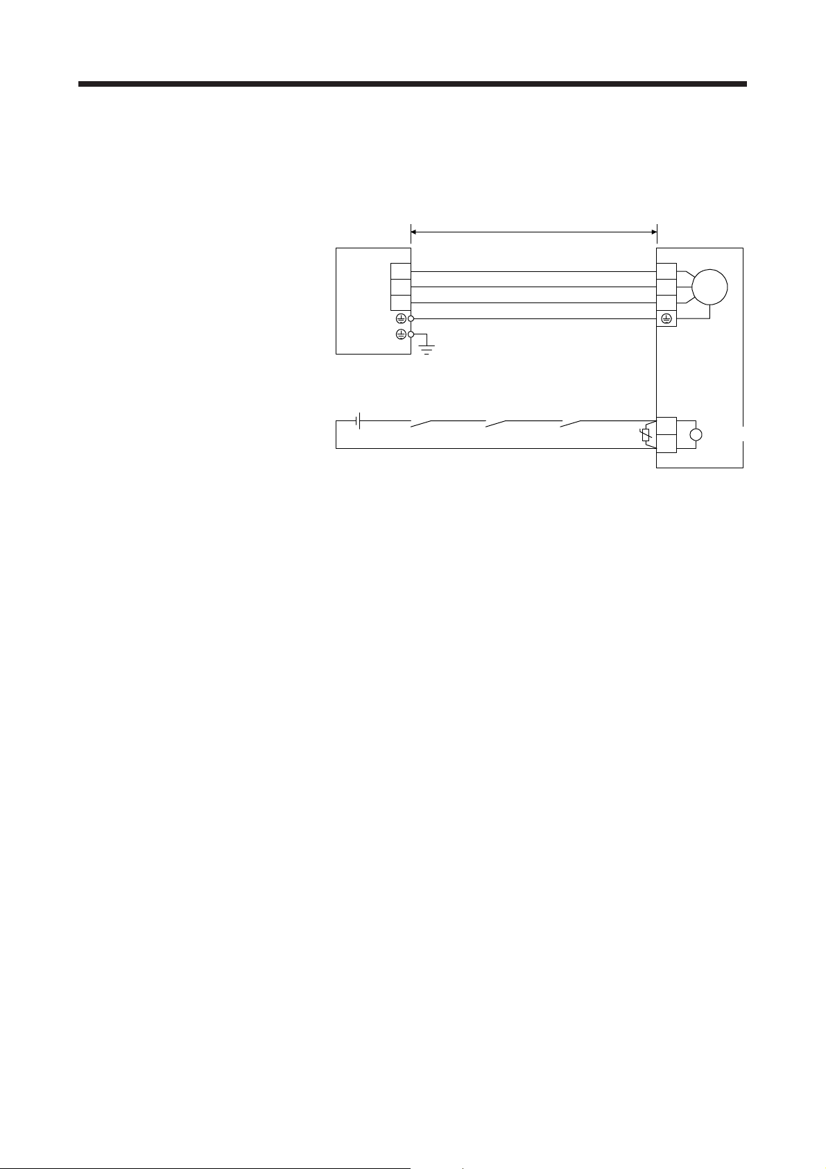
4.1 Connection instructions
To avoid a malfunction, connect the wires to the correct phase terminals (U/V/W)
of the servo amplifier and servo motor.
Do not connect AC power supply directly to the servo motor. Otherwise, it may
cause a malfunction.
CAUTION
For grounding, connect the grounding lead wire from the servo motor to the protective earth (PE) terminal of
the servo amplifier, and then connect the wire from the servo amplifier to the ground via the protective earth
of the cabinet. Do not connect the wire directly to the protective earth of the cabinet.
Do not use the 24 V DC interface power supply for the electromagnetic brake.
Always use the power supply designed exclusively for the electromagnetic brake.
Otherwise, it may cause a malfunction.
POINT
Refer to chapter 5 for the selection of the encoder cable.
Refer to the chapter of the servo motor series for the selection of a surge
absorber for the electromagnetic brake.
Cabinet
Servo motorServo amplifier
PE
terminal
(Note)
Note. The number of PE terminals of the servo amplifier differs depending on the amplifier
types.
4 - 2

4. CONNECTION OF SERVO AMPLIFIER AND SERVO MOTOR
r
4.2 Wiring
To wire to the servo amplifier, use connectors packed with the amplifier or optional connectors. For servo
amplifier terminals, refer to each servo amplifier instruction manual.
4.2.1 HG-KN series servo motor
(1) Servo motor power supply cable wiring diagrams
(a) When cable length is 10 m or less
10 m or less
MR-PWS1CBL_M-A1-L
MR-PWS1CBL_M-A2-L
CNP3
U
V
MR-PWS1CBL_M-A1-H
MR-PWS1CBL_M-A2-H
(Red)
(White)
(Black)
(Green/yellow)
Servo motorServo amplifier
U
V
WW
M
(b) When cable length exceeds 10 m
Fabricate an extension cable as shown below. In addition, the motor power supply cable should be
within 2 m.
Refer to section 4.3 for the wire used for the extension cable.
Servo amplifier
CNP3
U
V
Note. Use of the following connectors is recommended when ingress protection (IP65) is necessary.
Junction connector
a) Junction connector for
extension cable
b)
Junction connector for
motor power supply cable
50 m or less 2 m or less
Extension cable
(Note)
a) Junction connector for
extension cable
Connector: RM15WTPZ-4P(71)
Cord clamp: JR13WCC-5(72)
(Hirose Electric)
Connector: RM15WTJZ-4S(81)
Cord clamp: JR13WCC-8(72)
(Hirose Electric)
Numeral changes depending on the cable OD.
Numeral changes depending on the cable OD.
MR-PWS1CBL2M-A1-L
MR-PWS1CBL2M-A2-L
MR-PWS1CBL2M-A1-H
MR-PWS1CBL2M-A2-H
MR-PWS2CBL03M-A1-L
MR-PWS2CBL03M-A2-L
(Red)
(White)
(Black)
(Green/yellow)
(Note)
b) Junction connector for
motor power supply cable
Description IP rating
Servo moto
U
V
M
WW
IP65
IP65
4 - 3

4. CONNECTION OF SERVO AMPLIFIER AND SERVO MOTOR
(2) Electromagnetic brake cable wiring diagrams
(a) When cable length is 10 m or less
10 m or less
MR-BKS1CBL_M-A1-L
MR-BKS1CBL_M-A2-L
(Note 3)
24 V DC power supply
for electromagnetic
brake
Note 1. Connect a surge absorber as close to the servo motor as possible.
2. There is no polarity in electromagnetic brake terminals (B1/B2).
3. Do not use the 24 V DC interface power supply for the electromagnetic brake.
4. Create the circuit in order to shut off by interlocking with the emergency stop switch.
(Electromagnetic
brake interlock)
When fabricating the electromagnetic brake cable MR-BKS1CBL-_M_, refer to section 5.4 and
section 5.5.
(b) When cable length exceeds 10 m
Fabricate an extension cable as shown below. In addition, the electromagnetic brake cable should
be within 2 m.
Refer to section 4.3 for the wire used for the extension cable.
(Note 5)
24 V DC power supply
for electromagnetic
brake
(Electromagnetic
brake interlock)
MBR
MBR
ALM
(Malfunction)
50 m or less
Extension cable
(To be fabricated)
ALM
(Malfunction)
(Note 4)
(Note 1)
(Note 3)
(Note 1)
MR-BKS1CBL_M-A1-H
MR-BKS1CBL_M-A2-H
U
MR-BKS1CBL2M-A1-L
MR-BKS1CBL2M-A2-L
MR-BKS1CBL2M-A1-H
MR-BKS1CBL2M-A2-H
MR-BKS2CBL03M-A1-L
MR-BKS2CBL03M-A2-L
U
AWG 20
AWG 20
2 m or less
AWG 20
AWG 20
Servo motor
(Note 2)
B1
B
B2
Servo motor
(Note 4)
B1
B
B2
(Note 2)
a) Junction connector for
extension cable
Note 1. Connect a surge absorber as close to the servo motor as possible.
2. Use of the following connectors is recommended when ingress protection (IP65) is necessary.
Junction connector Description IP rating
Junction connector for
a)
extension cable
b)
Junction connector for
electromagnetic brake cable
3. Create the circuit in order to shut off by interlocking with the emergency stop switch.
4. There is no polarity in electromagnetic brake terminals (B1/B2).
5. Do not use the 24 V DC interface power supply for the electromagnetic brake.
CM10-CR2P- (DDK)
Wire size: S, M, L
CMV1-SP2S- (DDK)
Wire size: S, M1, M2, L
(Note 2)
b) Junction connector for
electromagnetic brake cable
IP65
IP65
4 - 4
4. CONNECTION OF SERVO AMPLIFIER AND SERVO MOTOR
4.2.2 HG-SN series servo motor
Refer to section 4.3 for the wires used for wiring.
(1) Wiring
50 m or less
(Note 4) CNP2
U
V
W
Servo motorServo amplifier
U
V
W
M
(Note 2)
24 V DC power supply
for electromagnetic
brake
Note 1. There is no polarity in electromagnetic brake terminals (B1/B2).
2. Do not use the 24 V DC interface power supply for the electromagnetic brake.
3. Create the circuit in order to shut off by interlocking with the emergency stop switch.
4. The name and shape of connector differ depending on the servo amplifier types.
MBR
(Electromagnetic
brake interlock)
RA2
ALM
(Malfunction)
RA1
(Note 3)
RA3
B1
U
B2
(Note 1)
B
4 - 5

4. CONNECTION OF SERVO AMPLIFIER AND SERVO MOTOR
(2) Connector
The connector fitting the servo motor is prepared as optional equipment. Refer to chapter 5 for details of
the options. For types other than those prepared as optional equipment, refer to chapter 3.
Servo motor
HG-SN52
HG-SN102
HG-SN152
HG-SN202
HG-SN302
Encoder Power supply
CMV1-R10P
(DDK)
The followings show the encoder connector, power connector, and electromagnetic brake connector
viewed from the connection side.
Encoder connector
CMV1-R10P
Power connector
MS3102A18-10P
MS3102A22-22P
Terminal
7
10
9
8
3
6
2
5
1
4
9
10 SHD
No.
1 MR A U
2 MRR B V B1
3 C W
4 BAT
5 LG (PE)
6
7
8 P5
Signal
CD
AB
Terminal
No.
D
Servo motor-side connectors
MS3102A18-10P
MS3102A22-22P
Electromagnetic brake connector
Signal
Electromagnetic
CMV1-R2P
Terminal
No.
12
1
2
Note. For the motor
brake
CMV1-R2P
(DDK)
with an
electromagnetic
brake, supply
electromagnetic
brake power
(24 V DC).
There is no
polarity.
Signal
(Note)
(Note)
B2
4 - 6

4. CONNECTION OF SERVO AMPLIFIER AND SERVO MOTOR
4.3 Selection example of wires
POINT
Wires indicated in this section are separated wires. When using a cable for
power line (U/V/W) between the servo amplifier and servo motor, use a 600 V
grade EP rubber insulated chloroprene sheath cab-tire cable (2PNCT). For
selection of cables, refer to app. 6.
To comply with the UL/CSA standard, use the wires shown in app. 4 for wiring.
To comply with other standards, use a wire that is complied with each standard.
Selection conditions of wire size are as follows.
Construction condition: Single wire set in midair
Wire length: 30 m or less
The following diagram shows the wires used for wiring. Use the wires given in this section or equivalent.
Servo amplifier
1) Servo motor power lead
Servo motor
U
V
W
2) Electromagnetic
brake lead
Encoder cable
U
V
Motor
W
B1
B2
Encoder
Electromagnetic
brake
The following shows examples for using the 600 V Grade heat-resistant polyvinyl chloride insulated wire
(HIV wire).
Table 4.1 Wire size selection example 2 (HIV wire)
Servo motor
HG-KN13
HG-KN23
HG-KN43
HG-KN73
HG-SN52
HG-SN102
HG-SN152
HG-SN202
HG-SN302 3.5 (AWG 12)
1) U/V/W/ 2) B1/B2
0.75 (AWG 18) (Note) 0.5 (AWG 20) (Note)
1.25 (AWG 16)
2 (AWG 14)
Wire [mm
2
]
1.25 (AWG 16)
Note. It is for 10 m wire length. When fabricating an extension cable, use 1.25 mm2 (AWG 16).
4 - 7

4. CONNECTION OF SERVO AMPLIFIER AND SERVO MOTOR
MEMO
4 - 8

5. WIRING OPTION
5. WIRING OPTION
Before connecting options, turn off the power and wait for 15 minutes or more
WARNING
until the charge lamp turns off. Otherwise, an electric shock may occur. In
addition, when confirming whether the charge lamp is off or not, always confirm it
from the front of the servo amplifier.
CAUTION
5.1 Cable/connector sets
Please purchase the cable and connector options indicated in this section for the servo motor.
Use specified options. Otherwise, it may cause a malfunction or fire.
POINT
The IP rating indicated for cables and connectors is their protection against
ingress of dust and raindrops when they are connected to a servo motor. If the
IP rating of the cable, connector, and servo motor vary, the overall IP rating
depends on the lowest IP rating of all components.
5 - 1

5. WIRING OPTION
r
5.1.1 Combinations of cable/connector sets
(1) HG-KN series servo motor
Servo amplifier
Direct connection (cable length 10 m or less, IP65)
13) 14) 15) 16)
CNP1
CN2
Junction connection (cable length more than
10 m, IP65)
Junction connection (cable length more than
10 m, IP20)
To 24 V DC
power supply for
electromagnetic
brake
24) 25)
19) 20)
7) 8) 9) 10)
1) 2) 3) 4)
Power supply
connector
26)
21)
11) 12)
5) 6)
22) 23)
17) 18)
Electromagnetic
brake connector
Servo
motor
HG-KN
Encoder
connector
(2) HG-SN series servo motor
Servo amplifier
(Note)
CNP2
Note. The name and shape of connector differ depending on the servo amplifier types. For connector details, refer to each
servo amplifier instruction manual.
CN2
24) 25)
29) 30) 32) 33)
27) 28)
Power supply
connector
26) 31) 34) 35)
Electromagnetic
brake connector
Servo motor
HG-SN
Encoder
connecto
5 - 2

5. WIRING OPTION
r
5.1.2 Cable and connector list
No. Product name Model Description Remark
1) Servo motor
power cable
2) Servo motor
power cable
3) Servo motor
power cable
4) Servo motor
power cable
5) Servo motor
power cable
6) Servo motor
power cable
7) Electromagnetic
brake cable
8) Electromagnetic
brake cable
9) Electromagnetic
brake cable
10) Electromagnetic
brake cable
MRPWS1CBL_MA1-L (Note)
Cable length:
2/5/10 m
MRPWS1CBL_MA1-H (Note)
Cable length:
2/5/10 m
MRPWS1CBL_MA2-L (Note)
Cable length:
2/5/10 m
MRPWS1CBL_MA2-H (Note)
Cable length:
2/5/10 m
MRPWS2CBL03M
-A1-L (Note)
Cable length:
0.3 m
MRPWS2CBL03M
-A2-L (Note)
Cable length:
0.3 m
MRBKS1CBL_MA1-L
Cable length:
2/5/10 m
MRBKS1CBL_MA1-H
Cable length:
2/5/10 m
MRBKS1CBL_MA2-L
Cable length:
2/5/10 m
MRBKS1CBL_MA2-H
Cable length:
2/5/10 m
Refer to section 5.3 for details.
Refer to section 5.3 for details.
Refer to section 5.3 for details.
Refer to section 5.3 for details.
Refer to section 5.4 for details.
Refer to section 5.4 for details.
Power supply connector
HG-KN series
Power supply connecto
HG-KN series
Power supply connector
HG-KN series
Power supply connector
HG-KN series
Electromagnetic brake connector
HG-KN series
Electromagnetic brake connector
HG-KN series
IP65
Load-side
lead
IP65
Load-side
lead
Long
bending life
IP65
Opposite
to loadside lead
IP65
Opposite
to loadside lead
Long
bending life
IP55
Load-side
lead
IP55
Opposite
to loadside lead
IP65
Load-side
lead
IP65
Load-side
lead
Long
bending life
IP65
Opposite
to loadside lead
IP65
Opposite
to loadside lead
Long
bending life
5 - 3

5. WIRING OPTION
r
No. Product name Model Description Remark
11) Electromagnetic
brake cable
12) Electromagnetic
brake cable
13) Encoder cable MR-
14) Encoder cable MR-
15) Encoder cable MR-
16) Encoder cable MR-
17) Encoder cable MR-
18) Encoder cable MR-
MRBKS2CBL03MA1-L
Cable length:
0.3 m
MRBKS2CBL03MA2-L
Cable length:
0.3 m
J3ENCBL_MA1-L (Note)
Cable length:
2/5/10 m
J3ENCBL_MA1-H (Note)
Cable length:
2/5/10 m
J3ENCBL_MA2-L (Note)
Cable length:
2/5/10 m
J3ENCBL_MA2-H (Note)
Cable length:
2/5/10 m
J3JCBL03MA1-L (Note)
Cable length:
0.3 m
J3JCBL03MA2-L (Note)
Cable length:
0.3 m
Refer to section 5.4 for details.
Electromagnetic brake connector
Refer to section 5.4 for details.
Refer to section 5.2 (1) for details.
Refer to section 5.2 (1) for details.
Refer to section 5.2 (3) for details.
Electromagnetic brake connecto
HG-KN series
HG-KN series
Encoder connector
HG-KN series
Encoder connector
HG-KN series
Encoder connector
HG-KN series
Encoder connector
HG-KN series
IP55
Load-side
lead
IP55
Opposite
to loadside lead
IP65
Opposite
to loadside lead
IP65
Load-side
lead
Long
bending life
IP65
Opposite
to loadside lead
IP65
Opposite
to loadside lead
Long
bending life
IP20
Load-side
lead
IP20
Opposite
to loadside lead
19) Encoder cable MR-EKCBL_M-
L
Cable length:
20/30 m
20) Encoder cable MR-EKCBL_M-
H
Cable length:
20/30/40/50 m
21) Encoder
connector set
MR-ECNM
Refer to section 5.2 (3) for details.
HG-KN series
Refer to section 5.2 (2) for details.
IP20
HG-KN series
Refer to section 5.2 (2) for details.
IP20
Long
bending life
IP20
5 - 4

5. WIRING OPTION
r
No. Product name Model Description Remark
22) Encoder cable MR-
J3JSCBL03MA1-L (Note)
Cable length:
0.3 m
Refer to section 5.2 (4) for details.
23) Encoder cable MR-
J3JSCBL03MA2-L (Note)
Cable length:
0.3 m
Refer to section 5.2 (4) for details.
24) Encoder cable MRJ3ENSCBL_ML (Note)
Cable length:
2/5/10/20/30 m
25) Encoder cable MRJ3ENSCBL_MH (Note)
Cable length:
2/5/10/20/30/40
/50 m
26) Encoder
connector set
HG-KN/HG-SN series
27) Power connector
set
28) Power connector
set
29) Electromagnetic
brake connector
set
30) Electromagnetic
brake connector
set
31) Encoder
Connector set
MR-J3SCNS
(Note)
MR-PWCNS4 Plug: CE05-6A18-10SD-D-BSS
MR-PWCNS5 Plug: CE05-6A22-22SD-D-BSS
MR-BKCNS1
(Note)
MR-BKCNS1A
(Note)
MR-J3SCNSA
(Note)
HG-KN/HG-SN series
Refer to section 5.2 (5) for details.
IP67
Refer to section 5.2 (5) for details.
Cable clamp: CE3057-10A-1-D
(DDK)
Applicable cable
Applicable wire size: 2 mm
Cable outer diameter: 10.5 mm to 14.1 mm
Cable clamp: CE3057-12A-1-D
(DDK)
Applicable cable
Applicable wire size: 5.5 mm
Cable outer diameter: 12.5 mm to 16 mm
Straight plug: CMV1-SP2S-L
Socket contact: CMV1-#22BSC-S2-100
(DDK)
Angle plug: CMV1-AP2S-L
Socket contact: CMV1-#22BSC-S2-100
(DDK)
2
to 3.5 mm
(AWG 14 to 12)
2
to 8 mm
(AWG 10 to 8)
Encoder connecto
HG-KN series
Encoder connector
HG-KN series
2
2
HG-SN series
HG-SN series
HG-SN52
HG-SN102
HG-SN152
HG-SN202
HG-SN302
IP65
Load-side
lead
IP65
Load-side
lead
IP67
Standard
bending life
Long
bending life
IP67
IP67
EN
compliant
IP67
EN
compliant
IP67
IP67
IP67
HG-SN series
Refer to section 5.2 (5) for details.
5 - 5

5. WIRING OPTION
No. Product name Model Description Remark
32) Electromagnetic
brake connector
set
33) Electromagnetic
brake connector
set
34) Encoder
connector set
HG-SN series
35) Encoder
connector set
MR-BKCNS2 Straight plug: CMV1S-SP2S-L
Socket contact: CMV1-#22BSC-S2-100
(DDK)
MR-BKCNS2A Angle plug: CMV1S-AP2S-L
Socket contact: CMV1-#22BSC-S2-100
(DDK)
MR-ENCNS2
Refer to section 5.2 (5) for details.
MR-ENCNS2A
HG-SN series
HG-SN series
IP67
IP67
IP67
IP67
HG-SN series
Refer to section 5.2 (5) for details.
Note. The cable and the connector set may contain different connectors but still usable.
5.2 Encoder cable/connector sets
POINT
For the CN2 side connector, securely connect the external conductor of the
shielded cable to the ground plate and fix it to the connector shell.
Cable
Ground plate
Screw
Encoder cables are not subject to European Low Voltage Directive (50 V AC to 1000 V AC and 75 V DC to
1500 V DC).
(1) MR-J3ENCBL_M-_-_
These cables are encoder cables for the HG-KN series servo motors. The numbers in the cable length
field of the table indicate the symbol filling the underline "_" in the cable model. The cables of the lengths
with the numbers are available.
Cable model
MR-J3ENCBL_M-A1-L 2 5 10 IP65 Standard
MR-J3ENCBL_M-A1-H 2 5 10 IP65
MR-J3ENCBL_M-A2-L 2 5 10 IP65 Standard
MR-J3ENCBL_M-A2-H 2 5 10 IP65
Cable length
2 m 5 m
IP rating Bending life Application
10 m
Long
bending life
Long
bending life
Load-side lead for HG-KN servo
motor
Opposite to load-side lead for HGKN servo motor
5 - 6

5. WIRING OPTION
(a) Connection of servo amplifier and servo motor
MR-J3ENCBL_M-A1-L
MR-J3ENCBL_M-A1-H
Servo amplifier
CN2
Cable model 1) CN2-side connector 2) Encoder-side connector
MR-J3ENCBL_M-A1-L Receptacle: 36210-0100PL
Shell kit: 36310-3200-008
(3M or equivalent)
MR-J3ENCBL_M-A1-H
MR-J3ENCBL_M-A2-L
MR-J3ENCBL_M-A2-H
2
LG 8
1
P5
View seen from the wiring side.
(Note)
Note. Do not connect anything to the pins shown as . Especially, pin
6
4
MRR
5
3
MR
10 is provided for manufacturer adjustment. If it is connected with any
other pin, the servo amplifier cannot operate normally. Referring to
POINT of section 5.2, securely connect the external conductor of the
shielded cable to the ground plate and fix it to the connector shell.
10
9
BAT
7
1)
MR-J3ENCBL_M-A2-L
MR-J3ENCBL_M-A2-H
1)
Connector set: 54599-1019
(Molex)
2
4
MRR
LG
or
1P53
View seen from the wiring side.
(Note)
5
MR
or
8610
79
BAT
2)
Servo motor
HG-KN
2)
Servo motor
HG-KN
Connector: 2174053-1
Crimping tool for ground clip:
1596970-1
Crimping tool for receptacle
contact: 1596847-1
(TE Connectivity)
SHD
9
7
5MR
3P5
1
View seen from the wiring side.
(Note)
Note. Do not connect anything
to the pins shown as
.
(b) Cable internal wiring diagram
CN2-side
connector
Encoder-side
connector
8
6LG
MRR
4
BAT
2
P5
LG
MR
MRR34
BAT BAT
SD Plate
1
2
9
3
P5
LG
6
5
4
2
9
MR
MRR
SHD
5 - 7

5. WIRING OPTION
r
(2) MR-EKCBL_M-_
POINT
The following encoder cables are of four-wire type.
MR-EKCBL30M-L
MR-EKCBL30M-H
MR-EKCBL40M-H
MR-EKCBL50M-H
When using these encoder cables, refer to each servo amplifier instruction
manual.
The servo amplifier and the servo motor cannot be connected by these cables alone. The servo motorside encoder cable (MR-J3JCBL03M-_-L) is required.
The numbers in the cable length field of the table indicate the symbol filling the underline "_" in the cable
model.
Cable model
MR-EKCBL_M-L 20
MR-EKCBL_M-H 20
Note. Four-wire type cable
(a) Connection of servo amplifier and servo motor
Cable length
20 m 30 m 40 m 50 m
(Note)
(Note)
IP20 Standard
30
(Note)
(Note)
30
40
50
IP rating Bending life Application
For HG-KN servo motor
Use in combination with MR-
J3JCBL03M-_-L.
IP20
Long
bending life
Servo amplifier
CN2
1)
Cable model 1) CN2-side connector 2) Junction connector
MR-EKCBL_M-L Receptacle: 36210-0100PL
Shell kit: 36310-3200-008
(3M)
MR-EKCBL_M-H
2
LG
15
P5
View seen from the wiring side.
(Note)
Note. Do not connect anything to the pins shown as . Especially, pin
6
4
MRR
37
MR
10 is provided for manufacturer adjustment. If it is connected with any
other pin, the servo amplifier cannot operate normally. Referring to
POINT of section 5.2, securely connect the external conductor of the
shielded cable to the ground plate and fix it to the connector shell.
8
MDR
MD
10
BAT
9
MR-EKCBL_M-L
MR-EKCBL_M-H
Connector set: 54599-1019
(Molex)
428610
or
13 79
P5 MR
View seen from the wiring side.
(Note)
MRR
LG
MDR
5
MD
BAT
MR-J3JCBL03M-A2-L
Cable length: 0.3 m
2)
Housing: 1-172161-9
Connector pin: 170359-1
Crimping tool: 91529-1
(TE Connectivity or equivalent)
Cable clamp: MTI-0002
(Toa Electric Industrial)
View seen from the wiring side.
123
MR
456
MD
789
P5
MRR
BAT
CONT
MDR
LG SHD
Servo moto
HG-KN
5 - 8

5. WIRING OPTION
(b) Internal wiring diagram
MR-EKCBL20M-L
CN2-side
connector
P5
LG
MR
MRR34
BAT BAT
SD Plate
1
2
9
(Note)
Junction
connector
7
8
1
2
3
9
P5
LG
MR
MRR
SHD
MR-EKCBL30M-L
CN2-side
connector
P5
LG
1
2
MR
MRR34
MD
MDR 8 5
BAT BAT
SD Plate
7
9
(Note)
Junction
connector
7
8
1
2
4
3
6 CONT
9
P5
LG
MR
MRR
MD
MDR
SHD
P5
LG
MR-EKCBL20M-H
CN2-side
connector
1
2
Junction
connector
7
8
P5
LG
P5
LG
MR-EKCBL30M-H
MR-EKCBL40M-H
MR-EKCBL50M-H
CN2-side
connector
1
2
Junction
connector
7
8
P5
LG
MR
MRR34
BAT BAT
SD Plate
9
(Note)
MR
1
MRR
2
3
9
SHD
MR
MRR34
MD
MDR
BAT BAT
SD Plate
7
85
9
(Note)
1
MR
MRR
2
4
MD
MDR
3
6
CONT
9
SHD
Note. Always make connection for use in an absolute position detection system. Wiring is not necessary
for use in an incremental system.
When fabricating the cable, use the wiring diagram corresponding to the length indicated below.
Cable bending life
Standard MR-EKCBL20M-L MR-EKCBL30M-L
Long bending life MR-EKCBL20M-H MR-EKCBL30M-H
Less than 30 m 30 m to 50 m
Applicable wiring diagram
MR-EKCBL40M-H
MR-EKCBL50M-H
5 - 9

5. WIRING OPTION
(c) When fabricating the encoder cable
Prepare the following parts, and fabricate it according to the wiring diagram in (b) in this section.
(3) MR-J3JCBL03M-_-L
Refer to section 5.5 for the specifications of the cable to use.
Parts Description
Connector set MR-ECNM
CN2-side connector
Receptacle: 36210-0100PL
Shell kit: 36310-3200-008
(3M)
or
Connector set: 54599-1019
(Molex)
Encoder-side connector
Housing: 1-172161-9
Connector pin: 170359-1
(TE Connectivity or equivalent)
Cable clamp: MTI-0002
(Toa Electric Industrial)
The servo amplifier and the servo motor cannot be connected by these cables alone. The servo motorside encoder cable (MR-EKCBL_M-_) is required.
Cable model Cable length IP rating Bending life Application
Use in combination with load-side
MR-J3JCBL03M-A1-L
0.3 m IP20 Standard
MR-J3JCBL03M-A2-L
lead for HG-KN servo motor MREKCBL_M-_.
Use in combination with opposite to
load-side lead for HG-KN servo motor
MR-EKCBL_M-_.
5 - 10

5. WIRING OPTION
(a) Connection of servo amplifier and servo motor
MR-J3JCBL03M-A1-L
Servo amplifier
CN2
Cable model 1) Junction connector 2) Encoder-side connector
MR-J3JCBL03M-A1-L Housing: 1-172169-9
Contact: 1473226-1
Cable clamp: 316454-1
Crimping tool: 91529-1
(TE Connectivity)
MR
MRR
MR-J3JCBL03M-A2-L
BAT
CONT
MDR
LGSHD
MD
P5
123
456
789
MR-EKCBL_M-_
Connector: 2174053-1
Crimping tool for ground clip: 1596970-1
Crimping tool for receptacle contact: 1596847-1
(TE Connectivity)
View seen from the wiring side.
1)
MR-J3JCBL03M-A2-L
1)
SHD
9
MDR
7
8
5MR
6LG
3P5
4
CONT
1
2
MD
MRR
BAT
2)
Servo motor
HG-KN
or
Servo motor
HG-KN
2)
(b) Internal wiring diagram
View seen from the wiring side.
Junction
connector
P5
LG
MR
MRR12
MD 4 8 MD
MDR 5 7 MDR
BAT BAT
SHD
7
8
32
6
9
Encoder-side
connector
3
6
5
4
1
9
P5
LG
MR
MRR
CONTCONT
SHD
5 - 11

5. WIRING OPTION
V
)
(4) MR-J3JSCBL03M-_-L
The servo amplifier and the servo motor cannot be connected by these cables alone. The servo motorside encoder cable (MR-J3ENSCBL_M-_) is required.
(a) Connection of servo amplifier and servo motor
Cable model Cable length IP rating Bending life Application
Use in combination with load-side lead
MR-J3JSCBL03M-A1-L
0.3 m IP65 Standard
MR-J3JSCBL03M-A2-L
for HG-KN servo motor MRJ3ENSCBL_M-_.
Use in combination with opposite to
load-side lead for HG-KN servo motor
MR-J3ENSCBL_M-_.
MR-J3JSCBL03M-A1-L
Servo amplifier
1)
(Note)
CN2
MR-J3ENSCBL_M-_
MR-J3JSCBL03M-A2-L
1)
Note. For details of this cable, refer to (5) in this section.
Cable model 1) Junction connector 2) Encoder-side connector
MR-J3JSCBL03M-A1-L Receptacle: CM10-CR10P-M
(DDK)
Applicable wire size: AWG 20 or less
1MR2
MRR
5
476
BAT
MR-J3JSCBL03M-A2-L
iew seen from the wiring side. (Note)
LG
98
P5
10
SHD
3
Connector: 2174053-1
Crimping tool for ground clip: 1596970-1
Crimping tool for receptacle contact: 1596847-1
(TE Connectivity)
SHD
9
7
5MR
3P5
1
View seen from the wiring side. (Note
or
8
6LG
MRR
4
BAT
2
2)
Servo motor
HG-KN
2)
Servo motor
HG-KN
Note. Do not connect anything to the pins shown as
.
Note. Do not connect anything to the pins shown as
.
5 - 12

5. WIRING OPTION
R
(b) Internal wiring diagram
Junction
connector
Encoder-side
connector
P5
LG
MR
MRR
BAT BAT
SHD
8
5
1
2
68
77
42
3
10
P5
3
LG
6
MR
5
MR
4
1
9
SHD
5 - 13

5. WIRING OPTION
V
(5) MR-J3ENSCBL_M-_
These cables are encoder cables for the HG-KN/HG-SN series servo motors. The numbers in the cable
length field of the table indicate the symbol filling the underline "_" in the cable model.
Cable model
MR-J3ENSCBL_M-L 2 5 10 20 30 IP67 Standard
MR-J3ENSCBL_M-H 2 5 10 20 30 40 50 IP67
(a) Connection of servo amplifier and servo motor
Cable length
2 m 5 m
10 m 20 m 30 m 40 m 50 m
IP rating Bending life Application
Long
bending life
For HG-KN/HG-SN series servo
motor
Servo amplifier
CN2
MR-J3ENSCBL_M-L
MR-J3ENSCBL_M-H
2)
Servo motor
HG-SN
1)
Cable model 1) CN2-side connector 2) Encoder-side connector
MR-J3ENSCBL_M-L Receptacle: 36210-0100PL
Shell kit: 36310-3200-008
(3M)
2
LG
15
P5
View seen from the wiring side.
(Note)
6
4
MRR
37
10
8
BAT
MR
9
or
Cable
length
10 m or
shorter
20 m or
more
Bending life
Long
bending life
Standard
Long
bending life
Standard CMV1-SP10S-M2
Straight plug Socket contact
CMV1-SP10S-M1
3
Connector set: 54599-1019
(Molex)
10
SHD
MR-J3ENSCBL_MH
428610
MRR
LG
13 79
P5 MR
5
BAT
iew seen from the wiring side. (Note)
Note. Do not connect anything to the pins shown as .
1
2
MRR
MR
5LG476
98
P5
Plug (DDK)
CMV1-#22ASC-C1-100
Applicable wire size:
Crimping tool: 357J-53162T
CMV1-#22ASC-C2-100
Applicable wire size:
Crimping tool: 357J-53163T
BAT
AWG 24 to 20
AWG 28 to 24
View seen from the wiring side.
(Note)
Note. Do not connect anything to
the pins shown as
.
Especially, pin 10 is provided
for manufacturer adjustment.
If it is connected with any
other pin, the servo amplifier
cannot operate normally.
Referring to POINT of section
5.2, securely connect the
external conductor of the
shielded cable to the ground
plate and fix it to the
connector shell.
5 - 14

5. WIRING OPTION
R
(b) Cable internal wiring diagram
MR-J3ENSCBL2M-L
MR-J3ENSCBL5M-L
MR-J3ENSCBL10M-L
MR-J3ENSCBL2M-H
MR-J3ENSCBL5M-H
MR-J3ENSCBL10M-H
CN2-side
connector
P5
LG
MR
MRR34
BAT BAT
SD
1
2
9
Plate
Encoder-side
connector
(Note)
10
P5
8
LG
5
MR
1
MR
2
4
SHD
MR-J3ENSCBL20M-L
MR-J3ENSCBL30M-L
CN2-side
connector
P5
LG
1
2
MR
MRR
BAT BAT
SD Plate
3
4
9
(Note)
Encoder-side
connector
8
5
1
2
4
10
P5
LG
MR
MRR
SHD
MR-J3ENSCBL20M-H
P5
LG
MR-J3ENSCBL30M-H
MR-J3ENSCBL40M-H
MR-J3ENSCBL50M-H
CN2-side
connector
1
2
Encoder-side
connector
8
P5
5
LG
10
1
MR
2
MRR
4
SHD
MR
MRR34
BAT BAT
SD Plate
9
(Note)
Note. Always make connection for use in an absolute position detection system. Wiring is not necessary
for use in an incremental system.
5 - 15
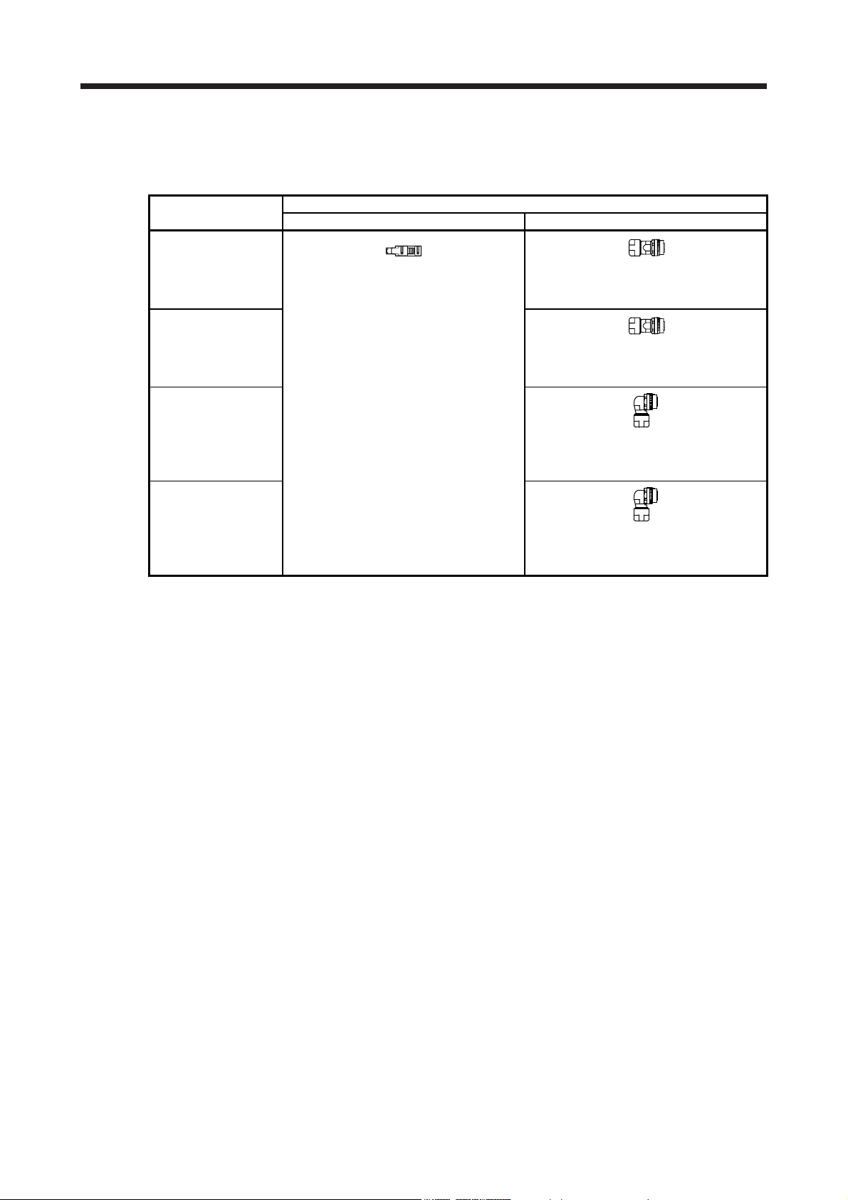
5. WIRING OPTION
(c) When fabricating the encoder cable
Prepare the following parts, and fabricate it according to the wiring diagram in (b) in this section.
Refer to section 5.5 for the specifications of the cable to use.
Parts
(Connector set)
MR-J3SCNS
(one-touch connection
type)
(Note)
MR-ENCNS2
(screw type)
(Note)
MR-J3SCNSA
(one-touch connection
type)
(Note)
MR-ENCNS2A
(screw type)
(Note)
Note. Cable clamp and bushing for 5.5 mm to 7.5 mm and 7.0 mm to 9.0 mm of cable outer diameter are included.
Receptacle: 36210-0100PL
Shell kit: 36310-3200-008
(3M)
Connector set: 54599-1019
(Molex)
Description
Servo amplifier-side connector Encoder-side connector (DDK)
Straight plug: CMV1-SP10S-M2
Socket contact: CMV1-#22ASC-S1-100
Applicable wire size: AWG 20 or less
or
Straight plug: CMV1S-SP10S-M2
Socket contact: CMV1-#22ASC-S1-100
Applicable wire size: AWG 20 or less
Angle plug: CMV1-AP10S-M2
Socket contact: CMV1-#22ASC-S1-100
Applicable wire size: AWG 20 or less
Angle plug: CMV1S-AP10S-M2
Socket contact: CMV1-#22ASC-S1-100
Applicable wire size: AWG 20 or less
5 - 16

5. WIRING OPTION
5.3 Servo motor power cable
These cables are servo motor power cables for the HG-KN series servo motors.
The numbers in the cable length field of the table indicate the symbol filling the underline "_" in the cable
model.
Refer to section 4.2.1 for wiring.
Cable model
MR-PWS1CBL_M-A1-L 2 5 10 IP65 Standard Load-side lead for HG-KN servo motor
MR-PWS1CBL_M-A2-L 2 5 10 IP65 Standard
MR-PWS1CBL_M-A1-H 2 5 10 IP65
MR-PWS1CBL_M-A2-H 2 5 10 IP65
MR-PWS2CBL03M-A1-L 03 IP55 Standard Load-side lead for HG-KN servo motor
MR-PWS2CBL03M-A2-L 03 IP55 Standard
(1) Connection of servo amplifier and servo motor
Cable length
0.3 m 2 m 5 m
IP rating Bending life Application
10 m
Opposite to load-side lead for HG-KN
servo motor
Long
bending life
Long
bending life
Load-side lead for HG-KN servo motor
Opposite to load-side lead for HG-KN
servo motor
Opposite to load-side lead for HG-KN
servo motor
MR-PWS1CBL_M-A1-L
MR-PWS1CBL_M-A1-H
MR-PWS2CBL03M-A1-L
Servo amplifier
Servo amplifier
power connector
(Note) CNP2
MR-PWS1CBL_M-A2-L
MR-PWS1CBL_M-A2-H
MR-PWS2CBL03M-A2-L
Note. The name and shape of connector differ depending on the servo amplifier types. For connector details, refer to
each servo amplifier instruction manual.
or
1)
Servo motor
HG-KN
1)
Servo motor
HG-KN
Cable model 1) Servo motor power-side connector
MR-PWS1CBL_M-A1-L
MR-PWS1CBL_M-A2-L
MR-PWS1CBL_M-A1-H
MR-PWS1CBL_M-A2-H
MR-PWS2CBL03M-A1-L
MR-PWS2CBL03M-A2-L
Connector: KN4FT04SJ1-R
Hood, socket insulator
Bushing, ground nut
Contact: ST-TMH-S-C1B-100-(A534G)
Crimping tool: CT170-14-TMH5B (JAE)
Connector: KN4FT04SJ2-R
Hood, socket insulator
Bushing, ground nut
Contact: ST-TMH-S-C1B-100-(A534G)
Crimping tool: CT170-14-TMH5B (JAE)
1
U
2
3
V
4
W
View seen from
the wiring side.
5 - 17

5. WIRING OPTION
(2) Internal wiring diagram
(Red)
(Note)
Note. These are not shielded cables.
(White)
(Black)
(Green/yellow)
U
V
W
5 - 18

5. WIRING OPTION
5.4 Electromagnetic brake cable
These cables are electromagnetic brake cables for the HG-KN series servo motors. The numbers in the
cable length field of the table indicate the symbol filling the underline "_" in the cable model.
Refer to section 4.2.1 for wiring.
Cable model
MR-BKS1CBL_M-A1-L 2 5 10 IP65 Standard Load-side lead for HG-KN servo motor
MR-BKS1CBL_M-A2-L 2 5 10 IP65 Standard
MR-BKS1CBL_M-A1-H 2 5 10 IP65
MR-BKS1CBL_M-A2-H 2 5 10 IP65
MR-BKS2CBL03M-A1-L 03 IP55 Standard Load-side lead for HG-KN servo motor
MR-BKS2CBL03M-A2-L 03 IP55 Standard
(1) Connection of power supply for electromagnetic brake and servo motor
Cable length
0.3 m 2 m 5 m
IP rating Bending life Application
10 m
Opposite to load-side lead for HG-KN
servo motor
Long
bending life
Long
bending life
MR-BKS1CBL_M-A1-L
MR-BKS1CBL_M-A1-H
MR-BKS2CBL03M-A1-L
Load-side lead for HG-KN servo motor
Opposite to load-side lead for HG-KN
servo motor
Opposite to load-side lead for HG-KN
servo motor
1)
Cable model 1) Connector for electromagnetic brake
MR-BKS1CBL_M-A1-L
MR-BKS1CBL_M-A2-L
MR-BKS1CBL_M-A1-H
MR-BKS1CBL_M-A2-H
MR-BKS2CBL03M-A1-L
MR-BKS2CBL03M-A2-L
(2) Internal wiring diagram
24 V DC power
supply for
electromagnetic
brake
+
-
Connector: JN4FT02SJ1-R
Hood, socket insulator
Bushing, ground nut
Contact: ST-TMH-S-C1B-100-(A534G)
Crimping tool: CT170-14-TMH5B (JAE)
Connector: JN4FT02SJ2-R
Hood, socket insulator
Bushing, ground nut
Contact: ST-TMH-S-C1B-100-(A534G)
Crimping tool: CT170-14-TMH5B (JAE)
AWG 20
(Note)
AWG 20
or
MR-BKS1CBL_M-A2-L
MR-BKS1CBL_M-A2-H
MR-BKS2CBL03M-A2-L
B1
B2
Servo motor
HG-KN
1)
Servo motor
HG-KN
View seen from wiring side.
1B1
B22
Note. These are not shielded cables.
5 - 19
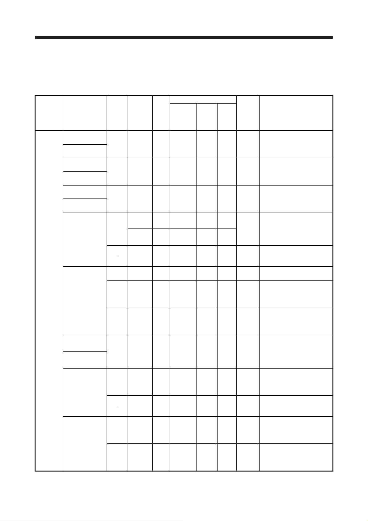
5. WIRING OPTION
5.5 Wires for option cables
When fabricating a cable, use the wire models given in the following table or equivalent.
Table 5.1 Wires for option cables
Characteristics of one core
(Note 2)
Cable OD
[mm]
OD
1.18 7.1
1.17 7.1
1.2 7.1 ± 0.3
1.18
7.0
1.50
1.2 8.2 ± 0.3
0.88 7.2
0.88 7.2
0.88 8.0
1.0 7.1 ± 0.3
1.18 7.1
1.2 8.2 ± 0.3
1.17 7.1
0.88 7.2
(Note 3)
VSVP 7/0.26 (AWG#22 or
equivalent)-3P
KB-1655-2 (Bando Densen)
(Note 3)
TPE•SVP 70/0.08 (AWG#22 or
equivalent)-3P
KB-2237-2 (Bando Densen)
T/2464-1061/IIA-SB
4P×26AWG (Taiyo Cabletec)
(Note 3)
20276 composite 6-core
shielded cable
Ban-gi-shi-16395-1 (Bando
Densen)
(Note 3)
20276 VSVPAWG#23×6P
KB-0492 (Bando Densen)
(Note 3) A14B2343 6P
(Junkosha)
(Note 3)
TPE•SVP 40/0.08 (AWG#24 or
equivalent)-6P
KB-1928-2 (Bando Densen)
(Note 3)
TPE•SVP 40/0.08 (AWG#24 or
equivalent)-7P
KB-1929-2 (Bando Densen)
(Note 3)
VSVP 7/0.16 (AWG#26 or
equivalent)-4P
Ban-gi-shi-16822 (Bando
Densen)
(Note 3)
VSVP 7/0.26 (AWG#22 or
equivalent)-3P
KB-1655-2 (Bando Densen)
(Note 3)
20276 VSVPAWG#23×6P
KB-0492 (Bando Densen)
(Note 3)
TPE•SVP 70/0.08 (AWG#22 or
equivalent)-3P
KB-2237-2 (Bando Densen)
(Note 3)
TPE•SVP 40/0.08 (AWG#24 or
equivalent)-6P
KB-1928-2 (Bando Densen)
Type Model
MR-J3ENCBL_MA1-L
MR-J3ENCBL_MA2-L
MR-J3ENCBL_MA1-H
MR-J3ENCBL_MA2-H
MR-J3JCBL03MA1-L
MR-J3JCBL03MA2-L
MR-EKCBL_M-L
MR-EKCBL_M-H
Encoder cable
MR-J3JSCBL03MA1-L
MR-J3JSCBL03MA2-L
MR-J3ENSCBL_
M-L
MR-J3ENSCBL_
M-H
Length
[m]
Core
size
2 to 10 AWG 22
2 to 10 AWG 22
0.3 AWG 26
AWG 28
2 to 10
AWG 22 2 17/0.16
20 30 AWG 23
2 to 10 0.2 mm
2
20 AWG 24
30 to 50
AWG 24
0.3 AWG 26
2 to 10 AWG 22
20 30 AWG 23
2 to 10 AWG 22
20 to 50
AWG 24
Number
of cores
6
(3 pairs)
6
(3 pairs)
8
(4 pairs)
4
(2 pairs)
12
(6 pairs)
12
(6 pairs)
12
(6 pairs)
14
(7 pairs)
8
(4 pairs)
6
(3 pairs)
12
(6 pairs)
6
(3 pairs)
12
(6 pairs)
Structure
[Wires/mm]
7/0.26
70/0.08
30/0.08
7/0.127
12/0.18
40/0.08
40/0.08
40/0.08
7/0.16
7/0.26
12/0.18
70/0.08
40/0.08
Conductor
resistance
[Ω/km]
53 or
less
56 or
less
233 or
less
232 or
less
28.7 or
less
63.6 or
less
105 or
less
105 or
less
105 or
less
146 or
less
53 or
less
63.3 or
less
56 or
less
105 or
less
(Note 1)
Insulator
d [mm]
Wire model
(Manufacturer)
5 - 20

5. WIRING OPTION
Type Model
MR-PWS1CBL_
M-A1-L
MR-PWS1CBL_
M-A2-L
MR-PWS1CBL_
M-A1-H
MR-PWS1CBL_
M-A2-H
MRPWS2CBL03MA1-L
MR-
Servo motor power supply cable
PWS2CBL03MA2-L
MR-BKS1CBL_
M-A1-L
MR-BKS1CBL_
M-A2-L
MR-BKS1CBL_
M-A1-H
MR-BKS1CBL_
M-A2-H
MRBKS2CBL03MA1-L
Electromagnetic brake cable
MRBKS2CBL03MA2-L
Note 1. The following shows the detail of d.
d
Length
[m]
2 to 10
2 to 10
2 to 10
2 to 10
0.3
0.3
2 to 10
2 to 10
2 to 10
2 to 10
0.3
0.3
Characteristics of one core
Core
Number
size
of cores
AWG 18 4 34/0.18
AWG 19
(0.75 mm2)
AWG 19 4 30/0.18
AWG 20 2 21/0.18
AWG 20 2 110/0.08
AWG 20 2 19/0.203
Structure
[Wires/m
m]
4 150/0.08
Conductor
resistance
[Ω/km]
21.8
or less
29.1
or less
25.8
or less
34.6
or less
39.0
or less
32.0
or less
(Note 1)
Insulator
d [mm]
(Note 2)
Cable OD
[mm]
OD
1.71 6.2 ± 0.3
1.63 5.7 ± 0.5
1.64 -
1.35 4.7 ± 0.1
1.37 4.5 ± 0.3
1.42 -
Wire model
(Manufacturer)
(Note 4)
HRZFEV-A(CL3) AWG 18 4
cores
(Dyden)
(Note 4)
RMFES-A(CL3X) AWG 19 4
cores
(Dyden)
(Note 3, 5)
J11B2330 UL10125
(Junkosha)
(Note 4)
HRZFEV-A(CL3) AWG 20 2
cores
(Dyden)
(Note 4)
RMFES-A(CL3X) AWG 20 2
cores
(Dyden)
(Note 3, 5)
J11B2331 UL10125
(Junkosha)
InsulatorConductor
2. Standard OD. Maximum OD is about 10% greater.
3. Purchase from Toa Electric Industrial
4. Purchase from Taisei Co., Ltd.
5. These models consist with solid wires. Specify the color, separately.
5 - 21

5. WIRING OPTION
MEMO
5 - 22

6. HG-KN SERIES
6. HG-KN SERIES
This chapter provides information on the servo motor specifications and characteristics. When using the HGKN series servo motor, always read the Safety Instructions in the beginning of this manual and chapters 1 to
5, in addition to this chapter.
6.1 Model designation
The following describes model designation. Not all combinations of the symbols are available.
G
HD
Series
Rated output
Symbol Rated output [kW]
1 0.1
2 0.2
4 0.4
7 0.75
Rated speed
3000 [r/min]
Electromagnetic brake
Symbol Electromagnetic brake
None None
B With
JB31-KN
Shaft type
Symbol Shaft shape
None
K
D
Oil seal
Symbol Oil seal
None None
J With
6.2 Combination list of servo motors and servo amplifiers
Servo motor Servo amplifier
HG-KN13
HG-KN23
HG-KN43
HG-KN73
Standard
(straight shaft)
Keyway shaft
(with key)
D cut shaft
MR-JE-10B(F)
MR-JE-20B(F)
MR-JE-40B(F)
MR-JE-70B(F)
HG-KN_
13 to 73
23 to 73
13
MR-JE-10A
MR-JE-10C
MR-JE-20A
MR-JE-20C
MR-JE-40A
MR-JE-40C
MR-JE-70A
MR-JE-70C
Appearance
6 - 1

6. HG-KN SERIES
6.3 Standard specifications
6.3.1 Standard specifications list
Servo motor
Item
Power supply capacity
Continuous running
duty (Note 1)
Maximum torque [N•m] 0.95 1.9 3.8 7.2
Rated speed (Note 1) [r/min] 3000
Maximum speed [r/min] 5000 (6000) (Note 9)
Instantaneous permissible speed [r/min] 5750 (6900) (Note 9)
Power rate at
continuous rated
torque
Rated current [A] 0.8 1.3 2.6 4.8
Maximum current [A] 2.4 3.9 7.8 14
Moment of inertia J
Recommended load to motor inertia ratio
(Note 2)
Speed/position
detector
Oil seal
Thermistor None
Insulation class 130 (B) (Note 8)
Structure Totally enclosed, natural cooling (IP rating: IP65 (Note 3))
Environment (Note 4)
Vibration rank (Note 6) V10
Permissible load for
the shaft (Note 7)
With oil seal
Mass
Without oil
seal
Rated output [kW] 0.1 0.2 0.4 0.75
Rated torque [N•m] 0.32 0.64 1.3 2.4
Standard [kW/s] 12.9 18.0 43.2 44.5
With an
electromagnetic brake
[kW/s]
Standard
With an
electromagnetic
brake
Combination with MRJE-_B(F)/MR-JE-_C
Combination with MRJE-_A
Ambient
temperature
Ambient
humidity
Ambience
Altitude Max. 2000 m above sea level (Note 10)
Vibration resistance
(Note 5)
L [mm] 25 30 40
Radial [N] 88 245 392
Thrust [N] 59 98 147
Standard [kg] 0.57 0.98 1.5 3.0
With an
electromagnetic brake
Standard [kg] 0.54 0.91 1.4
With an
electromagnetic brake
[× 10
[× 10
-4
kg•m2]
-4
kg•m2]
With
None
Operation
Storage
Operation
Storage
[kg]
[kg]
13(B)(J) 23(B)(J) 43(B)(J) 73(B)J
Refer to "Power supply equipment capacity and generated loss of servo
12.0 16.4 40.8 41.0
0.0783 0.225 0.375 1.28
0.0843 0.247 0.397 1.39
17-bit encoder common to absolute position/incremental systems
0.77 1.4 1.9 4.0
0.74 1.3 1.8
HG-KN series (low inertia/small capacity)
amplifiers" in Servo Amplifier Instruction Manual.
15 times or less
(resolution per servo motor revolution: 131072 pulses/rev)
Incremental 17-bit encoder system
(resolution per servo motor revolution: 131072 pulses/rev)
0 °C to 40 °C (non-freezing)
-15 °C to 70 °C (non-freezing)
10 %RH to 80 %RH (non-condensing)
10 %RH to 90 %RH (non-condensing)
Indoors (no direct sunlight), free from corrosive gas,
flammable gas, oil mist, dust, and dirt
X, Y: 49 m/s
2
6 - 2

6. HG-KN SERIES
Note 1. When the power supply voltage drops, the output and the rated speed cannot be guaranteed.
2. If the load to motor inertia ratio exceeds the indicated value, contact your local sales office.
3. Except for the shaft-through portion. IP classifies the degrees of protection provided against the intrusion of solid objects and
water in electrical enclosures.
4. In the environment where the servo motor is exposed to oil mist, oil, or water, the servo motor of the standard specifications
may not be usable. Please contact your local sales office.
5. The following figure shows the vibration directions. The value is the one at the part that indicates the maximum value (normally
the opposite to load-side bracket). When the servo motor stops, fretting is likely to occur at the bearing. Therefore, suppress
the vibration to about half of the permissible value.
Servo motor
X
Vibration
6. V10 indicates that the amplitude of a single servo motor is 10 μm or less. The following figure shows the servo motor mounting
position for measurement and the measuring position.
Servo motor
Top
Y
1000
100
10
Vibration amplitude
(both amplitudes) [μm]
0 1000 2000 3000 4000 5000 6000 7000
Measuring position
Speed [r/min]
Bottom
7. The following shows permissible load for the shaft. Do not subject the shaft to load greater than the value in the specifications
list. The value assumes that the load is applied independently.
L
Radial load
Thrust load
L: Distance from flange mounting surface to load center
8. When you conform HG-KN series servo motor to the UL/CSA standard as a certified product by UL, the insulation class will be
105 (A). The insulation class is approved for 130 (B) as for the UL/CSA standard by TÜV Rheinland.
9. Values in parentheses are applicable according to the parameter setting of the servo amplifier. For details, refer to each servo
amplifier instruction manual.
10. Follow the restrictions in section 2.11 when using the servo amplifiers at altitude exceeding 1000 m and up to 2000 m above
sea level.
6 - 3

6. HG-KN SERIES
6.3.2 Torque characteristics
POINT
For the system where the unbalanced torque occurs, such as a vertical axis
system, the unbalanced torque of the machine should be kept at 70% or lower of
the motor's rated torque.
When the power supply input of the servo amplifier is 3-phase 200 V AC or 1-phase 230 V AC, the torque
characteristic is indicated by the heavy line.
[HG-KN13]
1.4
1.2
1
0.8
Short-duration
running range
0.6
Torque [N•m]
0.4
0.2
Continuous
running range
0
1000 2000 3000 4000 5000 60000
Speed [r/min]
[HG-KN23]
2.5
2
1.5
1
Torque [N•m]
0.5
0
Short-duration
running range
Continuous
running range
1000 2000 3000 4000 5000 60000
Speed [r/min]
[HG-KN43]
5
4.5
4
3.5
3
2.5
2
Torque [N•m]
1.5
1
0.5
0
Short-duration
running range
Continuous
running range
1000 2000 3000 4000 5000 60000
Speed [r/min]
[HG-KN73]
9
8
7
6
5
4
3
Torque [N•m]
2
1
0
Short-duration
running range
Continuous
running range
1000 2000 3000 4000 5000 6000
0
Speed [r/min]
6 - 4

6. HG-KN SERIES
A
6.4 Electromagnetic brake characteristics
The electromagnetic brake is provided to prevent a drop at a power failure or
alarm occurrence during vertical drive or to hold a shaft at a stop. Do not use it for
normal braking (including braking at servo-lock).
CAUTION
The characteristics of the electromagnetic brake provided for the servo motor with an electromagnetic brake
are indicated below.
Item
Type (Note 1) Spring actuated type safety brake
Rated voltage (Note 4)
Power consumption [W] at 20 °C 6.3 7.9 10
Coil resistance (Note 6) [Ω] 91.0 73.0 57.0
Inductance (Note 6) [H] 0.15 0.18 0.13
Brake static friction torque [N•m] 0.32 1.3 2.4
Release delay time (Note 2) [s] 0.03 0.03 0.04
Braking delay time (Note 2) [s] DC off 0.01 0.02 0.02
Permissible braking work
Brake looseness at servo motor shaft (Note 5) [degree] 2.5 1.2 0.9
Brake life (Note 3)
Selection example of surge absorbers
to be used
(Note 7, 8)
Note 1. It does not have a manual release mechanism. When it is necessary to hand-turn the servo motor shaft
2. The value for initial on gap at 20 °C.
3. The brake gap will increase as the brake lining wears, but the gap is not adjustable. The brake life
4.
5. These are design values. These are not guaranteed values.
6. These are measured values. These are not guaranteed values.
7. Select the electromagnetic brake control relay properly, considering the characteristics of the
8. Manufactured by Nippon Chemi-Con Corporation.
Before operating the servo motor, be sure to confirm that the electromagnetic
brake operates properly.
The operation time of the electromagnetic brake varies depending on the power
supply circuit you use. Be sure to check the operation delay time with a real
machine.
Servo motor
13B(J) 23B(J) 43B(J) 73BJ
Per braking [J] 5.6 22 64
Per hour [J] 56 220 640
Work per braking [J] 5.6 22 64
for machine centering, etc., use a separate 24 V DC power supply to release the brake electrically.
indicated is the number of braking cycles after which adjustment will be required.
lways prepare a power supply exclusively used for the electromagnetic brake.
electromagnetic brake and surge absorber. When you use a diode for a surge absorber, the
electromagnetic braking time will be longer.
Number of
braking cycles
For the suppressed
voltage 125 V
For the suppressed
voltage 350 V
[times] 20000
HG-KN series
24 V DC
TND20V-680KB
TND10V-221KB
0
-10%
6 - 5
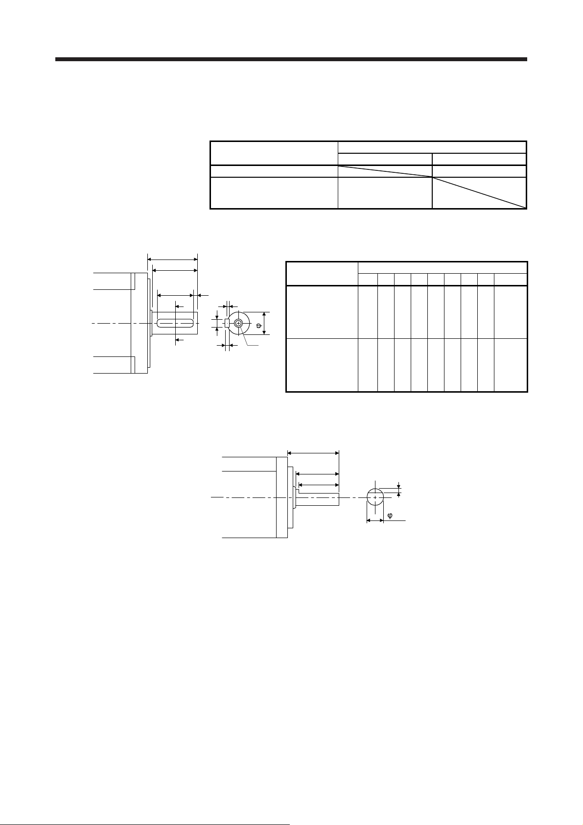
6. HG-KN SERIES
6.5 Servo motors with special shafts
The servo motors with special shafts indicated by the symbols (K/D) in the table are available. K and D are
the symbols included in the servo motor model names.
HG-KN13(B)(J)_ D
HG-KN23(B)(J)_
HG-KN43(B)(J)_
HG-KN73(B)J_
6.5.1 Key shaft (with 2 round end key)
Servo motor
Key shaft (with key) D cut shaft
Shaft shape
K
6.5.2 D cut shaft
R
Q
QK
QL
A
W
A
Shaft section view A-A
Servo motor
U
Y
T
HG-KN23(B)(J)K
HG-KN43(B)(J)K
S
HG-KN73(B)JK 19h6 40 37 6 25 5 3.5 6
25
21.5
20.5
S R Q W QK QL U T Y
14h6 30 27 5 20 3 3 5
[Unit: mm]
[Unit: mm]
Variable dimensions
M4
Screw
hole
depth
15
M5
Screw
hole
depth
20
1
8h6
6 - 6

6. HG-KN SERIES
6.6 Servo motor with oil seal
The oil seal prevents the entry of oil into the servo motor.
Install the servo motor horizontally, and set the oil level in the gear box to be lower than the oil seal lip
always.
Shaft
Gear
Servo motor
Height from oil (h)
Lip
Oil seal
Height (h) from
Servo motor
HG-KN13(B)J 10
HG-KN23(B)J
HG-KN43(B)J
HG-KN73(B)J
the surface of
the oil
[mm]
19
6 - 7

6. HG-KN SERIES
4
r
r
6.7 Mounting connectors
If the connector is not fixed securely, it may come off or may not produce a splash-proof effect during
operation.
To achieve the IP rating IP65, pay attention to the following points and install the connectors.
(1) When screwing the connector, hold the connector still and gradually tighten the screws in a crisscross
pattern.
2)
Tightening order
1)
3)
1) 2) 3) 4)
Tightening orde
1) 2)
)
2)
Connector for power, connector for encoder Connector for electromagnetic brake
(2) Tighten the screws evenly. Tightening torques are as indicated below.
Connector for encode
Screw size: M2
Tightening torque: 0.1 [N•m]
Connector for electromagnetic brake
Screw size: M2
Tightening torque: 0.2 [N•m]
Connector for power supply
Screw size: M2
Tightening torque: 0.2 [N•m]
1)
(3) The servo motor fitting part of each connector is provided with a splash-proof seal (O ring). When
mounting a connector, use care to prevent the seal (O ring) from dropping and being pinched. If the seal
(O ring) has dropped or is pinched, a splash-proof effect is not produced.
6 - 8

6. HG-KN SERIES
6.8 Dimensions
Moment of inertia on the table is the value calculated by converting the total value of moment of inertia for
servo motor and electromagnetic brake with servo motor shaft.
When running the cables to the load side, take care to avoid interference with the machine. The dimensions
without tolerances are general tolerance.
6.8.1 Standard (without an electromagnetic brake)
(1) With oil seal
Caution
plate
36
Bottom
Top
Motor plate
(opposite side)
Caution plate
Model Output [W] Moment of inertia J [× 10
HG-KN13J 100 0.0783 0.57
89
Bottom
Bottom
Top
Top
25
5
2.5
21.5
Oil seal
φ8h6
2-φ4.5 mounting hole
Use hexagon socket
head cap screw.
Caution plate
φ30h7
-4
kg•m2] Mass [kg]
°
5
4
φ
4
37.1
[Unit: mm]
Motor plate
□40
6
Encoder connector
13.7
1
1
2
2 3 4
3
4
4.9
27.4
Power supply connector
Pin No.
Application
1
2
3
4
(PE)
U
V
W
10.9
11.7
11.7
21.7 47.8
°
7
9.9
19.2
Power supply
connector
°
9
Encoder connector
21.7
11.7
11.7
Opposite-load side
19.2
13.9
27.5
9.9
6.4
Power supply
connector
BC43583*
6 - 9

6. HG-KN SERIES
Model Output [W] Moment of inertia J [× 10
HG-KN23J 200 0.225 0.98
-4
kg•m2] Mass [kg]
[Unit: mm]
4-φ5.8 mounting hole
Use hexagon socket
head cap screw.
26
φ50h7
φ14h6
Oil seal
Encoder connector
°
5
4
47.1
13.9 5.9
19.2
14 11.7
21.7
Opposite-load side
φ
7
0
27.8
□60
Power supply
connector
9.5
BC43584*
Motor
plate
46
Caution plate
Caution plate
Caution plate
Bottom
Top
Encoder connector
13.7 10
28.4
Power supply connector
1
2
3
4
Pin No.
1
2 3 4
Application
1
2
3
4
(PE)
U
V
W
10.9 19.2
88 30
Motor plate
(opposite side)
9.5
21.7
Bottom
Top
45.611.714
°
9
7 3
Bottom
Top
Power supply connector
°
7
Model Output [W] Moment of inertia J [× 10
-4
kg•m2] Mass [kg]
HG-KN43J 400 0.375 1.5
[Unit: mm]
4-φ5.8 mounting hole
Motor
plate
46
1
2
3
4
13.7 10
28.4
Power supply connector
Pin No.
1
2 3 4
1
2
3
4
Bottom
Top
Encoder connector
Application
(PE)
U
V
W
Caution
plate
Caution
plate
109.7 30
21.7
Motor plate
(opposite side)
9.5
Caution plate
10.9 19.2
Bottom
Top
Power supply
connector
67.311.714
°
9
°
7
7 3
Bottom
Top
Use hexagon socket
head cap screw.
26
φ50h7
φ14h6
Oil seal
Encoder connector
47.1
19.2
14 11.7
21.7
Opposite-load side
□60
°
5
4
φ
7
0
13.9 5.9
27.8
Power supply
connector
9.5
BC43585*
6 - 10

6. HG-KN SERIES
Model Output [W] Moment of inertia J [× 10
HG-KN73J 750 1.28 3.0
-4
kg•m2] Mass [kg]
[Unit: mm]
Motor
plate
56
13.7 11.5
1
1 2 3 4
2
3
4
Bottom
Top
Encoder connector
Power supply connector
Pin No.
Application
1
2
3
4
(PE)
U
V
W
Caution
plate
Caution
plate
Caution plate
9.510.7
14 11.7 19.2
21.7
Motor plate
(opposite side)
Bottom
Top
Power supply
connector
77.627.4
°
7
°
7
8 3
Bottom
Top
40
36
φ19h6
Oil seal
Encoder connector
4-φ6.6 mounting hole
Use hexagon socket
head cap screw.
φ70h7
57.1
14 11.7
21.7
Opposite-load side
°
5
4
φ9
0
27.8
9.519.2
□80122.2
1214
Power supply
connector
BC43586*
(2) Without oil seal
Motor plate
Caution plate
36
13.7
Power supply connector
1
2
3
4
Pin No.
1234
1
2
3
4
20.720.5
Caution plate
Bottom
Top
Encoder connector
4.9
Application
(PE)
U
V
W
20.7
21
Caution plate
10.9
11.7
11.7
21.7 39.8
Model Output [W] Moment of inertia J [× 10
-4
kg•m2] Mass [kg]
HG-KN13 100 0.0777 0.54
[Unit: mm]
11.711.7
4
13.9
□40
°
5
φ
4
6
27.527.4
Power supply
connector
19.2
82.4
Motor plate
(Opposite side)
9.9
19.2
°
7
Bottom
Top
5
Bottom
Top
Power supply connector
°
9
25
2.5
Encoder connector
2-φ4.5 mounting hole
Use hexagon socket
head cap screw.
21.5
6
h
8
φ
φ30h7
37.1
21.7
Opposite-load side
BC43576*
6.4
9.9
6 - 11

6. HG-KN SERIES
Model Output [W] Moment of inertia J [× 10
HG-KN23 200 0.221 0.91
-4
kg•m2] Mass [kg]
[Unit: mm]
Motor
plate
46
76.6 30
Motor plate
Caution
plate
(Opposite side)
Caution plate
Bottom
Top
13.7 10
28.4
Power supply connector
1
2
3
4
1234
Pin No.
1
2
3
4
Caution plate
Encoder connector
Application
(PE)
U
V
W
10.9
11.8
9.5
19.2
11.7
21.7
Bottom
Top
36.4
73
Bottom
Top
Power supply connector
7
9
26
φ14h6
Encoder connector
mounting hole
4-φ5.8
Use hexagon socket
head cap screw.
φ50h7
47.1
11.8
21.7
□60
5
4
φ
7
0
13.9 5.9
27.8
19.2
11.7
Opposite-load side
Power supply
connector
9.5
BC43577*
Motor plate
46
1
2
3
4
13.7 10
28.4
Power supply connector
Pin No.
123
4
1
2
3
4
Bottom
Top
Encoder connector
Application
(PE)
U
V
W
Caution plate
Caution plate
98.3 30
Caution plate
10.9 19.2
21.7
Motor plate
(Opposite side)
9.5
Model Output [W] Moment of inertia J [× 10
-4
kg•m2] Mass [kg]
HG-KN43 400 0.371 1.4
[Unit: mm]
Bottom
Top
Power supply
connector
58.111.711.8
°
9
°
7
73
Bottom
Top
4-φ5.8 mounting hole
Use hexagon socket
head cap screw.
26
φ50h7
φ14h6
Encoder connector
47.1
11.8 11.7
21.7
□60
°
5
4
φ
7
0
13.9 5.9
27.8
19.2
Opposite-load side
Power supply
connector
9.5
BC43578*
6 - 12

6. HG-KN SERIES
6.8.2 With an electromagnetic brake
(1) With oil seal
Caution
plate
38.8
Bottom
Top
36
Model Output [W] Brake static friction torque [N•m] Moment of inertia J [× 10
HG-KN13BJ 100 0.32 0.0843 0.77
129.6
Motor plate
(opposite side)
Caution plate
Bottom
Top
5
Bottom
Top
2-φ4.5 mounting hole
Use hexagon socket
head cap screw.
25
2.5
21.5
Oil seal
φ8h6
Caution
plate
φ30h7
-4
kg•m2] Mass [kg]
[Unit: mm]
□40
°
5
4
φ
4
6
37.1
Motor plate
Encoder connector
27.4
Pin No.
1
2
3
4
Pin No.
1
2
4.9
Application
(PE)
U
V
W
Application
B1
B2
13.7
1
2
3
4
1
2
Power supply connector
1 2 3 4
Electromagnetic brake connector
1
2
10.9
11.7
11.7
21.7 47.8
°
9
18.457.4
Encoder connector
Electromagnetic brake connector
°
7
9.9
19.2
Power supply
connector
°
3
1
11.711.7 9.9
21.7
18.4
57.4
Opposite-load side
27.5
6.4
Power supply
connector
13.9
Electromagnetic brake
connector
BC43587*
6 - 13

6. HG-KN SERIES
Motor plate
47.1
1
2
13.7 10
28.4
Power supply connector
1
2
3
Pin No.
1
2
3 4
4
Electromagnetic brake connector
Pin No.
1
2
Bottom
Top
Encoder connector
1
2
3
4
1
2
Model Output [W] Brake static friction torque [N•m] Moment of inertia J [× 10
-4
kg•m2] Mass [kg]
HG-KN23BJ 200 1.3 0.247 1.4
4-φ5.8 mounting hole
Use hexagon socket
head cap screw.
Application
(PE)
U
V
W
Application
B1
B2
Caution plate
Caution
plate
Caution
plate
10.9 19.2
21.7
60
°
9
124.8 30
Motor plate
(opposite side)
9.5
7 3
Bottom
Top
Bottom
Top
Power supply connector
45.611.714
Electromagnetic brake connector
Encoder connector
°
5
°
.
7
13
26
φ14h6
Oil seal
φ50h7
47.1
14 11.7
60
21.7
□60
°
5
4
φ
7
0
13.9 5.9
27.8
18.3
Opposite-load side
Electromagnetic brake
connector
[Unit: mm]
Power supply
connector
9.5
BC43588*
Motor plate
47.1
1
2
3
4
1
2
Bottom
Top
Encoder connector
13.7 10
28.4
Power supply connector
Pin No.
1
2 3 4
Application
1
2
U
3
4
W
Electromagnetic brake connector
Pin No.
1
2
Application
1
2
B1
B2
Model Output [W] Brake static friction torque [N•m] Moment of inertia J [× 10
-4
kg•m2] Mass [kg]
HG-KN43BJ 400 1.3 0.397 1.9
[Unit: mm]
4-φ5.8 mounting hole
Use hexagon socket
head cap screw.
7 3
Bottom
Top
26
φ14h6
Oil seal
φ50h7
47.1
□60
°
5
4
φ
7
0
13.9 5.9
27.8
Caution
plate
Caution
plate
146.5 30
Caution plate
9.5 Power supply
10.9 19.2
21.7
60
Electromagnetic brake connector
Motor plate
(opposite side)
Bottom
Top
connector
67.311.714
(PE)
Power supply
V
°
9
°
5°
7
13.
Encoder connector
14 11.7
21.7
18.3
60
Opposite-load side
connector
9.5
Electromagnetic brake
connector
BC43589*
6 - 14

6. HG-KN SERIES
Model Output [W] Brake static friction torque [N•m] Moment of inertia J [× 10
HG-KN73BJ 750 2.4 1.39 4.0
-4
kg•m2] Mass [kg]
[Unit: mm]
Motor
plate
56
13.7 11.5
1
2
3
4
1
1
2
2
Bottom
Top
Encoder connector
Power supply connector
Pin No.
1 2 3 4
Electromagnetic brake connector
Pin No.
Application
1
2
3
4
Application
1
2
W
B1
B2
(PE)
U
V
Caution
plate
Caution
plate
Caution plate
14 11.7 19.2
21.7
65.3
°
7
9.510.7
Electromagnetic brake connector
Motor plate
(opposite side)
Bottom
Top
Power supply
connector
77.627.4
7
°
7
8 3
Bottom
Top
°
Encoder connector
40
36
Oil seal
21.7
4-φ6.6 mounting hole
Use hexagon socket
head cap screw.
φ19h6
φ70h7
57.1
14 11.7
18.4
65.3
Opposite-load side
□80162.5
°
5
4
φ
9
0
1214
27.8
Power supply
connector
9.5
Electromagnetic brake
connector
BC43590*
6 - 15

6. HG-KN SERIES
(2) Without oil seal
20.720.5
Motor
plate
Caution
plate
36
38.8
13.7
27.4
Caution plate
Bottom
Top
Encoder connector
4.9
Model Output [W] Brake static friction torque [N•m] Moment of inertia J [× 10
-4
kg•m2] Mass [kg]
HG-KN13B 100 0.32 0.0837 0.74
[Unit: mm]
2-φ4.5 mounting hole
Use hexagon socket
20.7
21
10.9
11.7
11.7
21.7
123
Caution plate
18.458.8
Motor plate
(Opposite side)
9.9
19.2
39.8
Bottom
Top
5
2.5
Bottom
Top
Power supply
connector
Electromagnetic brake
connector
head cap screw.
25
21.5
φ8h6
φ30h7
37.1
13.9
□40
°
5
4
φ
4
6
6.4
27.5
Power supply connector
1
2
3
4
Pin No.
1234
1
2
3
4
Application
(PE)
U
V
W
Electromagnetic brake connector
1
2
Pin No.
1
2
1
2
°
9
Application
B1
B2
Encoder connector
°
7
1
2
21.7
°
3
1
Power supply
connector
11.711.7
58.8
18.4
Opposite-load side
9.9
Electromagnetic brake
connector
BC43580*
6 - 16

6. HG-KN SERIES
Motor plate
47.1
1
2
3
4
Bottom
Top
13.7
10
28.4
Power supply connector
Pin No.
1234
1
2
3
4
HG-KN23B 200 1.3 0.243 1.3
Caution plate
Caution plate
Encoder connector
Application
(PE)
U
V
W
Model Output [W] Brake static friction torque [N•m] Moment of inertia J [× 10
4-φ5.8mounting hole
Use hexagon socket
head cap screw.
26
φ14h6
11.8 11.7
21.7
φ50h7
47.1
18.3
57.8
Opposite-load side
Caution plate
10.9
11.711.8
21.7
57.8
°
9
Electromagnetic brake connector
1
2
Pin No.
21
Application
1
2
113.4 30
Motor plate
(Opposite side)
9.5
19.2
Electromagnetic brake connector
73
Bottom
Bottom
Top
Top
36.4
°
°
7
5
.
3
1
Encoder connector
Power supply connector
B1
B2
-4
kg•m2] Mass [kg]
[Unit: mm]
□60
°
5
4
φ
7
0
13.9
5.9
27.8
Power supply
connector
9.5
Electromagnetic brake
connector
BC43581*
Motor
plate
47.1
Power supply connector
1
1234
2
3
4
13.7 10
28.4
Pin No.
1
2
3
4
Bottom
Top
Encoder connector
Application
(PE)
U
V
W
Model Output [W] Brake static friction torque [N•m] Moment of inertia J [× 10
-4
kg•m2] Mass [kg]
HG-KN43B 400 1.3 0.393 1.8
[Unit: mm]
Caution
plate
Caution
plate
10.9
11.711.8
21.7
Electromagnetic brake connector
1
2
Pin No.
1
2
57.8
°
9
1
2
135.1 30
Caution plate
Motor plate
(Opposite side)
Bottom
Top
Power supply
9.5
connector
19.2
58.1
Electromagnetic brake connector
°
5
.
3
1
Encoder connector
Application
B1
B2
°
7
73
Bottom
Top
4-φ5.8mounting hole
Use hexagon socket
head cap screw.
26
φ14h6
11.8 11.7
21.7
φ50h7
47.1
18.3
57.8
Opposite-load side
□60
°
5
4
φ
7
0
13.9
Electromagnet ic brake
connector
27.8
Power supply
connector
9.5
5.9
BC43582*
6 - 17

6. HG-KN SERIES
MEMO
6 - 18

7. HG-SN SERIES
7. HG-SN SERIES
This chapter provides information on the servo motor specifications and characteristics. When using the HGSN series servo motor, always read the Safety Instructions in the beginning of this manual and chapters 1 to
5, in addition to this chapter.
7.1 Model designation
The following describes model designation. Not all combinations of the symbols are available.
HG - S JNK2B5
Appearance
Series
Rated output
Symbol Rated output [kW]
5 0.5
10 1.0
15 1.5
20 2.0
30 3.0
Rated speed
2000 [r/min]
Note. Key is not included.
7.2 Combination list of servo motors and servo amplifiers
Servo motor Servo amplifier
HG-SN52
HG-SN102
HG-SN152
HG-SN202
HG-SN302
Shaft type
Symbol Shaft shape
None
K (Note) Keyway shaft
With oil seal
Electromagnetic brake
Symbol Electromagnetic brake
None None
B With
Standard
(straight shaft)
MR-JE-70A
MR-JE-70B(F)
MR-JE-70C
MR-JE-100A
MR-JE-100B(F)
MR-JE-100C
MR-JE-200A
MR-JE-200B(F)
MR-JE-200C
MR-JE-300A
MR-JE-300B(F)
MR-JE-300C
7 - 1

7. HG-SN SERIES
7.3 Standard specifications
7.3.1 Standard specifications list
HG-SN series
Item
Power supply capacity
Continuous running
duty (Note 1)
Servo motor
(3-phase 200 V AC compatible, medium inertia/medium capacity)
52(B)J 102(B)J 152(B)J 202(B)J 302(B)J
Refer to "Power supply equipment capacity and generated loss of servo amplifiers" in
Servo Amplifier Instruction Manual.
Rated output [kW] 0.5 1.0 1.5 2.0 3.0
Rated torque [N•m] 2.39 4.77 7.16 9.55 14.3
Maximum torque [N•m] 7.16 14.3 21.5 28.6 42.9
Rated speed (Note 1) [r/min] 2000
Maximum speed [r/min] 3000 2500
Instantaneous permissible speed [r/min] 3450 2875
Power rate at
continuous rated
torque
Standard [kW/s] 7.85 19.7 32.1 19.5 26.1
With an
electromagnetic brake
6.01 16.5 28.2 16.1 23.3
[kW/s]
Rated current [A] 2.9 5.6 9.4 9.6 11
Maximum current [A] 9.0 17 29 31 33
Standard
-4
[× 10
kg•m2]
Moment of inertia J
With an
electromagnetic brake
-4
[× 10
kg•m2]
Recommended load to motor inertia ratio
(Note 2)
Combination with MRSpeed/position
detector
JE-_B(F)/MR-JE-_C
Combination with MR-
JE-_A
7.26 11.6 16.0 46.8 78.6
9.48 13.8 18.2 56.5 88.2
15 times or less
17-bit encoder common to absolute position/incremental systems
(resolution per servo motor revolution: 131072 pulses/rev)
Incremental 17-bit encoder system
(resolution per servo motor revolution: 131072 pulses/rev)
Oil seal With
Thermistor None
Insulation class 155 (F)
Structure Totally enclosed, natural cooling (IP rating: IP67 (Note 3))
0 °C to 40 °C (non-freezing)
-15 °C to 70 °C (non-freezing)
10 %RH to 80 %RH (non-condensing)
10 %RH to 90 %RH (non-condensing)
flammable gas, oil mist, dust, and dirt
Environment (Note 4)
Ambient
temperature
Ambient
humidity
Operation
Storage
Operation
Storage
Ambience
Indoors (no direct sunlight), free from corrosive gas,
Altitude Max. 2000 m above sea level (Note 8)
Vibration resistance
(Note 5)
X, Y: 24.5 m/s
2
X: 24.5 m/s
Y: 49 m/s
2
2
Vibration rank (Note 6) V10
Permissible load for
the shaft
(Note 7)
L [mm] 55 79
Radial [N] 980 2058
Thrust [N] 490 980
Standard [kg] 4.8 6.2 7.3 11 16
Mass
With an
electromagnetic brake
6.7 8.2 9.3 17 22
[kg]
7 - 2

7. HG-SN SERIES
Note 1. When the power supply voltage drops, the output and the rated speed cannot be guaranteed.
2. If the load to motor inertia ratio exceeds the indicated value, contact your local sales office.
3. Except for the shaft-through portion. IP classifies the degrees of protection provided against the intrusion of solid objects and
water in electrical enclosures.
4. In the environment where the servo motor is exposed to oil mist, oil, or water, the servo motor of the standard specifications
may not be usable. Please contact your local sales office.
5. The following figure shows the vibration directions. The value is the one at the part that indicates the maximum value (normally
the opposite to load-side bracket). When the servo motor stops, fretting is likely to occur at the bearing. Therefore, suppress
the vibration to about half of the permissible value.
Servo motor
X
Vibration
6. V10 indicates that the amplitude of a single servo motor is 10 μm or less. The following figure shows the servo motor mounting
position for measurement and the measuring position.
Top
Y
Servo motor
Measuring position
1000
100
10
(both amplitudes) [ m]
Vibration amplitude
0 1000 2000 3000
Speed [r/min]
Bottom
7. The following shows permissible load for the shaft. Do not subject the shaft to load greater than the value in the specifications
list. The value assumes that the load is applied independently.
L
Radial load
Thrust load
L: Distance from flange mounting surface to load center
8. Follow the restrictions in section 2.11 when using the servo amplifiers at altitude exceeding 1000 m and up to 2000 m above
sea level.
7 - 3

7. HG-SN SERIES
7.3.2 Torque characteristics
POINT
For the system where the unbalanced torque occurs, such as a vertical axis
system, the unbalanced torque of the machine should be kept at 70% or lower of
the motor's rated torque.
When the power supply input of the servo amplifier is 3-phase 200 V AC or 1-phase 230 V AC, the torque
characteristic is indicated by the heavy line. HG-SN52, HG-SN102, HG-SN152, and HG-SN202 support
single-phase power supply.
[HG-SN52]
9
[HG-SN102]
15
[HG-SN152]
24
[HG-SN202]
30
[HG-SN302]
45
Torque [N•m]
6
3
0
Short-duration
running range
Continuous
running range
1000 2000 30000
Speed [r/min]
10
Short-duration
running range
5
Torque [N•m]
Continuous
running range
0
1000 2000 30000
Speed [r/min]
16
Short-duration
running range
8
Torque [N•m]
Continuous
running range
0
1000 2000 30000
Speed [r/min]
20
Short-duration
running range
10
Torque [N•m]
Continuous
running range
0
1000 2000 30000
Speed [r/min]
30
Torque [N•m]
15
0
Short-duration
running range
Continuous
running range
1000 2000 25000
Speed [r/min]
7 - 4
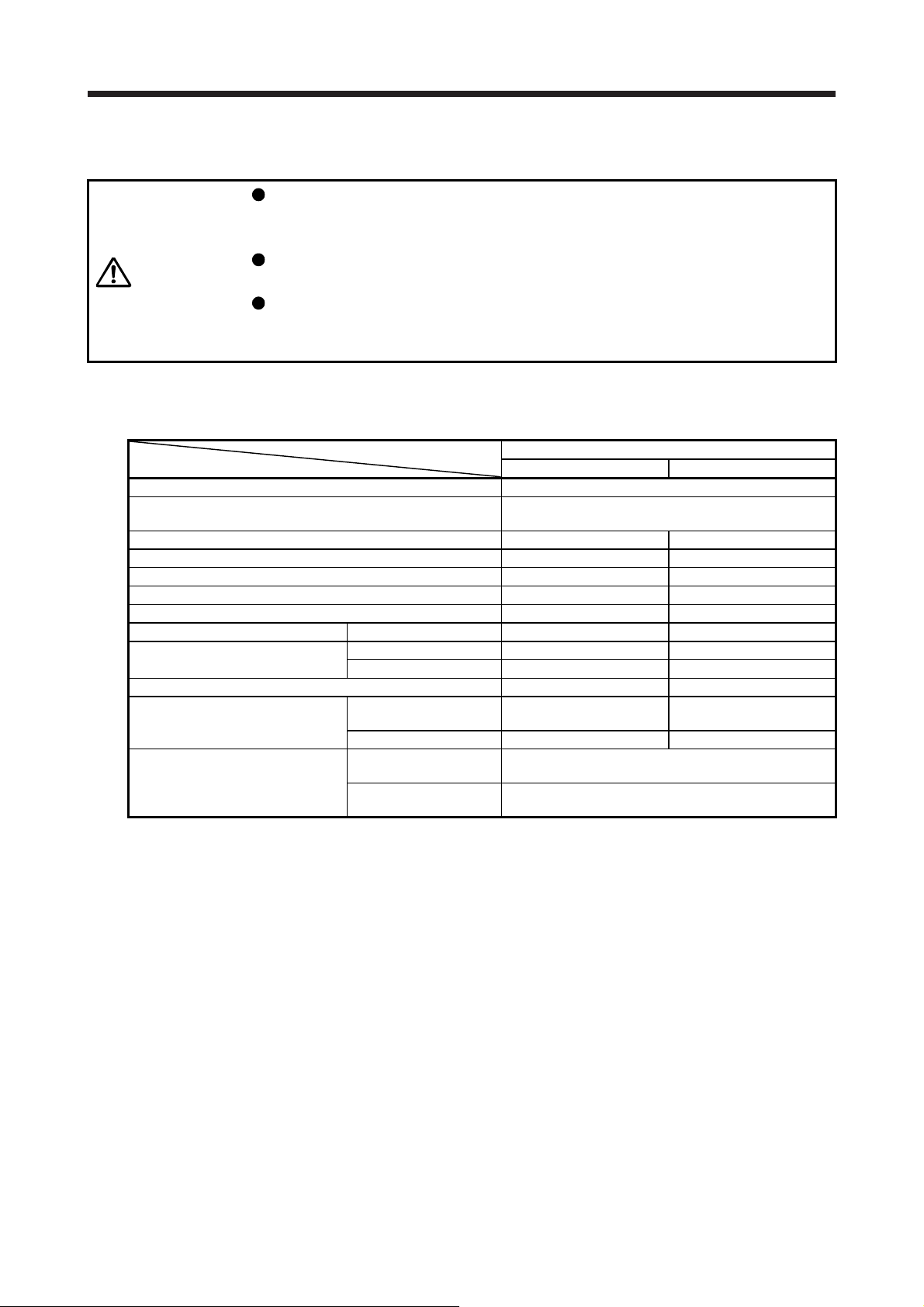
7. HG-SN SERIES
A
7.4 Electromagnetic brake characteristics
The electromagnetic brake is provided to prevent a drop at a power failure or
alarm occurrence during vertical drive or to hold a shaft at a stop. Do not use it for
normal braking (including braking at servo-lock).
CAUTION
The characteristics of the electromagnetic brake provided for the servo motor with an electromagnetic brake
are indicated below.
Item
Type (Note 1) Spring actuated type safety brake
Rated voltage (Note 4)
Power consumption [W] at 20 °C 20 34
Coil resistance (Note 6) [Ω] 29.0 16.8
Inductance (Note 6) [H] 0.80 1.10
Brake static friction torque [N•m] 8.5 44
Release delay time (Note 2) [s] 0.04 0.1
Braking delay time (Note 2) [s] DC off 0.03 0.03
Permissible braking work
Brake looseness at servo motor shaft (Note 5) [degrees] 0.2 to 0.6 0.2 to 0.6
Brake life (Note 3)
Selection example of surge absorbers
to be used
(Note 7, 8)
Note 1. It does not have a manual release mechanism. When it is necessary to hand-turn the servo motor shaft for machine
centering, etc., use a separate 24 V DC power supply to release the brake electrically.
2. The value for initial on gap at 20 °C.
3. The brake gap will increase as the brake lining wears, but the gap is not adjustable.
The brake life indicated is the number of braking cycles after which adjustment will be required.
4.
5. These are design values. These are not guaranteed values.
6. These are measured values. These are not guaranteed values.
7. Select the electromagnetic brake control relay properly, considering the characteristics of the electromagnetic brake
8. Manufactured by Nippon Chemi-Con Corporation.
lways prepare a power supply exclusively used for the electromagnetic brake.
and surge absorber. When you use a diode for a surge absorber, the electromagnetic braking time will be longer.
Before operating the servo motor, be sure to confirm that the electromagnetic
brake operates properly.
The operation time of the electromagnetic brake varies depending on the power
supply circuit you use. Be sure to check the operation delay time with a real
machine.
Servo motor
52BJ/102BJ/152BJ 202BJ/302BJ
Per braking [J] 400 4500
Per hour [J] 4000 45000
Number of
braking cycles
Work per braking [J] 200 1000
For the suppressed
voltage 125 V
For the suppressed
voltage 350 V
[times] 20000 20000
HG-SN series
24 V DC
TND20V-680KB
TND10V-221KB
0
-10%
7 - 5

7. HG-SN SERIES
4
7.5 Servo motors with special shafts
The servo motors with special shafts indicated by the symbol (K) in the table are available. K is the symbol
attached to the servo motor model names.
Servo motor
HG-SN_(B)JK K
R
Q
QK
QL
A
W
A
r Y
Shaft section view A-A
Key shaft (without key)
U
Servo motor
HG-SN52(B)JK
HG-SN102(B)JK
S
HG-SN152(B)JK
HG-SN202(B)JK
HG-SN302(B)JK
Shaft shape
Key shaft (without key)
S R Q W QK QL U r Y
24h6 55 50
+0.010
35
79 75
0
[Unit: mm]
Variable dimensions
M8
Screw
4
hole
depth
20
M8
Screw
5
hole
depth
20
10
0
8
36 5
-0.036
0
55 5
-0.036
+0.2
0
+0.2
5
0
7.6 Servo motor with oil seal
The oil seal prevents the entry of oil into the servo motor.
Install the servo motor horizontally, and set the oil level in the gear box to be lower than the oil seal lip
always.
Shaft
Gear
Servo motor
Height from oil (h)
Lip
Oil seal
Height (h) from
Servo motor
the surface of
the oil
[mm]
HG-SN52(B)J
HG-SN102(B)J
23
HG-SN152(B)J
HG-SN202(B)J
HG-SN302(B)J
31
7 - 6

7. HG-SN SERIES
7.7 Dimensions
Moment of inertia on the table is the value calculated by converting the total value of moment of inertia for
servo motor and electromagnetic brake with servo motor shaft.
The dimensions without tolerances are general tolerance.
7.7.1 Standard (without an electromagnetic brake)
-4
kg•m2] Mass [kg]
[Unit: mm]
4-φ9 mounting hole
Use hexagon socket
head cap screw.
□130
4
5
°
5
4
1
φ
φ
1
6
5
Motor plate
Bottom
Top
Bottom
Top
Caution plate
Caution plate
Bottom
Top
50.9
Model Output [kW] Moment of inertia J [× 10
HG-SN52J 0.5 7.26 4.8
Motor plate
(opposite side)
38.2
Caution
plate
12 3
Bottom
Top
55118.5
50
φ24h6
φ110h7
Oil seal
Motor plate
Bottom
Top
Bottom
Top
Caution plate
Encoder connector
CMV1-R10P
Power supply connector
MS3102A18-10P
Caution plate
Bottom
Top
50.9
13
38.2
CD
AB
(PE)
Key
13.5
U
58
BC43591*
-4
kg•m2] Mass [kg]
W
20.9
57.8
V
Power supply connector
Motor flange direction
Model Output [kW] Moment of inertia J [× 10
HG-SN102J 1.0 11.6 6.2
[Unit: mm]
4-φ9 mounting hole
Motor plate
(opposite side)
Caution
plate
12 3
Bottom
Top
55132.5
50
φ24h6
φ110h7
Oil seal
Use hexagon socket
head cap screw.
□130
4
5
°
5
4
1
φ
φ
1
6
5
112.5
Encoder connector
CMV1-R10P
Power supply connector
MS3102A18-10P
13
20.9
71.8
W
V
Power supply connector
Motor flange direction
CD
AB
(PE)
Key
13.5
U
58
BC43592*
112.5
7 - 7

7. HG-SN SERIES
Motor plate
Bottom
Top
Bottom
Top
Caution plate
Caution plate
Bottom
Top
50.9
Encoder connector
CMV1-R10P
Power supply connector
MS3102A18-10P
Model Output [kW] Moment of inertia J [× 10
-4
kg•m2] Mass [kg]
HG-SN152J 1.5 16.0 7.3
[Unit: mm]
4-φ9 mounting hole
13.5
58
Use hexagon socket
head cap screw.
□130
4
5
°
5
4
1
φ
φ
1
6
5
BC43593*
112.5
Motor plate
(opposite side)
38.2
Caution
plate
12 3
Bottom
Top
55146.5
50
φ24h6
φ110h7
Oil seal
13
W
(PE)
Key
CD
20.9
85.8
Power supply connector
Motor flange direction
AB
U
V
Motor plate
Bottom
Top
Bottom
Top
Caution plate
Caution plate
Bottom
Top
Encoder connector
CMV1-R10P
Power supply connector
MS3102A22-22P
50.9
13
Motor plate
(opposite side)
38.5
Model Output [kW] Moment of inertia J [× 10
-4
kg•m2] Mass [kg]
HG-SN202J 2.0 46.8 11
[Unit: mm]
4-φ13.5 mounting hole
Use hexagon socket
head cap screw.
138.5
Caution
plate
24.8
18 3
Bottom
Top
74.8
79
75
0
+0.01
φ35
Oil seal
CD
AB
(PE)
U
W
V
Power supply connector
Motor flange direction
0
-0.025
φ114.3
Key
□176
82
4
5
°
00
2
φ
φ
2
3
BC43594*
0
140.9
7 - 8

7. HG-SN SERIES
Motor plate
Bottom
Top
Model Output [kW] Moment of inertia J [× 10
-4
kg•m2] Mass [kg]
HG-SN302J 3.0 78.6 16
[Unit: mm]
Motor plate
(opposite side)
79162.5
*1
*2
98.8
18 3
Bottom
Top
75
0
+0.01
φ35
0
-0.025
CD
AB
φ114.3
(PE)
Key
U
Oil seal
W
V
Power supply connector
Motor flange direction
38.5
Caution plate
Caution
plate
*1
Caution plate
Bottom
Top
Bottom
Top
50.9
*2
Encoder connector
CMV1-R10P
Power supply connector
MS3102A22-22P
13
24.8
4-φ13.5 mounting hole
Use hexagon socket
head cap screw.
□176
4
5
°
0
20
φ
φ
2
3
0
82
BC43571*
140.9
7.7.2 With an electromagnetic brake
Model Output [kW] Brake static friction torque [N•m] Moment of inertia J [× 10
HG-SN52BJ 0.5 8.5 9.48 6.7
Motor plate
Bottom
Top
Bottom
Top
29
Caution plate
Caution plate
Bottom
Top
79.9
Encoder connector
CMV1-R10P
Electromagnetic brake connector
CMV1-R2P
Motor plate
43.5
(opposite side)
Caution plate
50.9
13
59
Power supply connector
MS3102A18-10P
20.9
12 3
Bottom
Top
57.8
55153
50
Oil seal
Main key
position mark
-4
kg•m2] Mass [kg]
[Unit: mm]
4-φ9 mounting hole
Use hexagon socket
head cap screw.
□130
4
5
°
5
4
1
φ24h6
φ110h7
φ
φ
1
6
5
112.5
W
(PE)
13.5
58
Key
Electromagnetic brake
Electromagnetic brake connector
Motor flange direction
Power supply connector
Motor flange direction
U
V
BC43595*
7 - 9

7. HG-SN SERIES
Motor plate
Bottom
Top
Bottom
Top
29
Model Output [kW] Brake static friction torque [N•m] Moment of inertia J [× 10
-4
kg•m2] Mass [kg]
HG-SN102BJ 1.0 8.5 13.8 8.2
[Unit: mm]
4-φ9 mounting hole
Use hexagon socket
head cap screw.
13.5
□130
4
5
°
5
4
1
φ
φ
1
6
5
58
BC43596*
Caution plate
Caution plate
Bottom
Top
50.9
79.9
Encoder connector
CMV1-R10P
Electromagnetic brake connector
CMV1-R2P
13
Power supply connector
MS3102A18-10P
43.5
Motor plate
(opposite side)
Caution plate
59
Electromagnetic brake
Electromagnetic brake connector
12 3
Bottom
Top
20.9
71.8
Motor flange direction
55167
50
Oil seal
Main key
position mark
Power supply connector
Motor flange direction
W
CD
V
φ24h6
φ110h7
(PE)
Key
AB
U
112.5
Motor plate
Bottom
Top
Bottom
Top
29
Model Output [kW] Brake static friction torque [N•m] Moment of inertia J [× 10
-4
kg•m2] Mass [kg]
HG-SN152BJ 1.5 8.5 18.2 9.3
[Unit: mm]
4-φ9 mounting hole
Use hexagon socket
head cap screw.
13.5
□130
4
5
°
5
4
1
φ
φ
1
6
5
58
BC43597*
43.5
Caution plate
Caution
plate
Bottom
Top
50.9
79.9
Encoder connector
CMV1-R10P
Electromagnetic brake connector
CMV1-R2P
13
Power supply connector
MS3102A18-10P
Motor plate
(opposite side)
Caution plate
59
Electromagnetic brake
Electromagnetic brake connector
12 3
Bottom
Top
20.9
85.8
Motor flange direction
55181
50
Oil seal
Main key
position mark
Power supply connector
Motor flange direction
W
CD
V
φ24h6
φ110h7
(PE)
Key
AB
U
112.5
7 - 10
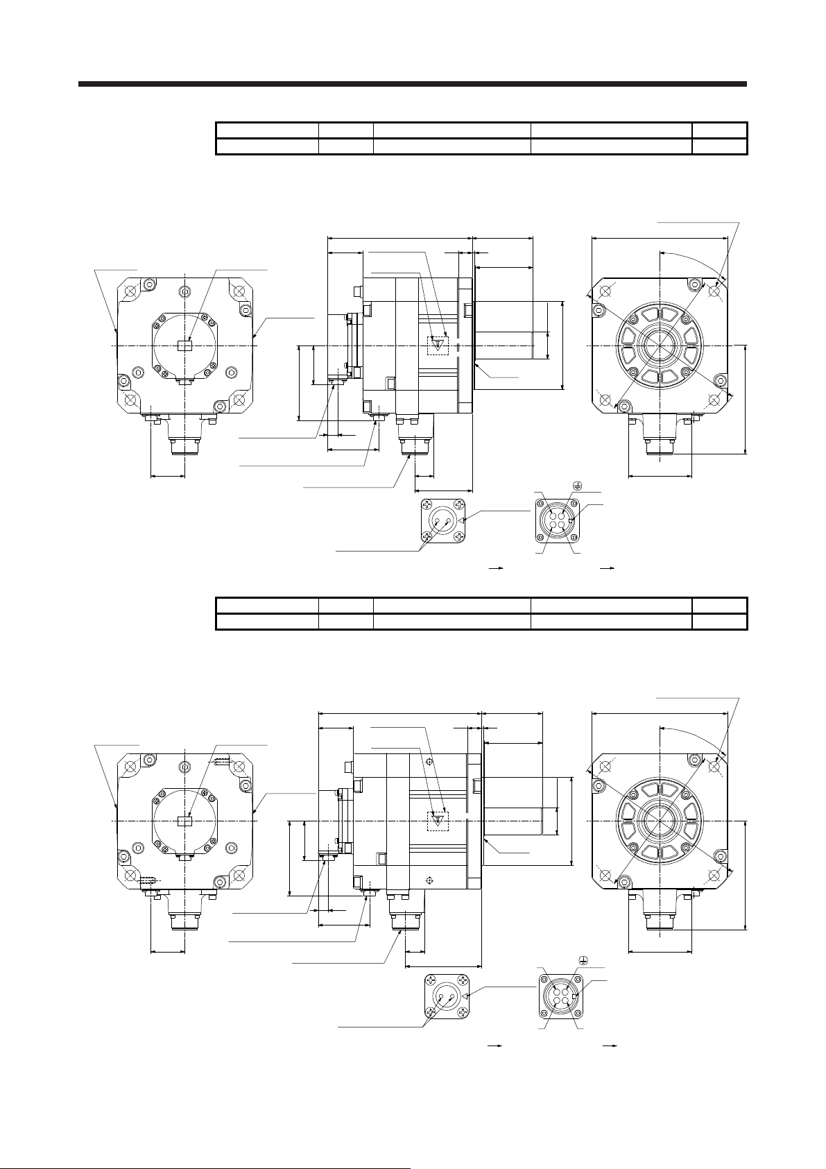
7. HG-SN SERIES
Motor plate
Bottom
Top
Bottom
Top
44
Model Output [kW] Brake static friction torque [N•m] Moment of inertia J [× 10
-4
kg•m2] Mass [kg]
HG-SN202BJ 2.0 44 56.5 17
[Unit: mm]
4-φ13.5 mounting hole
Use hexagon socket
head cap screw.
□176
82
4
5
°
0
0
2
φ
φ
2
3
0
BC43598*
Caution plate
Caution plate
Bottom
Top
96.9
Encoder connector
CMV1-R10P
Electromagnetic brake connector
CMV1-R2P
Power supply connector
MS3102A22-22P
45.5
50.9
13
66.5
Electromagnetic brake
Motor plate
(opposite side)
Caution plate
18 3
Bottom
Top
24.8
74.8
Electromagnetic brake connector
Motor flange direction
79188
75
Oil seal
Main key
position mark
Power supply connector
Motor flange direction
0
+0.01
φ35
W
CD
V
0
-0.025
φ114.3
(PE)
Key
AB
U
140.9
Motor plate
Bottom
Top
Model Output [kW] Brake static friction torque [N•m] Moment of inertia J [× 10
-4
kg•m2] Mass [kg]
HG-SN302BJ 3.0 44 88.2 22
[Unit: mm]
4-φ13.5 mounting hole
Use hexagon socket
head cap screw.
45.5
Caution plate
Motor plate
(opposite side)
Caution plate
*1
Caution plate
Bottom
Top
Bottom
Top
50.9
*2
Encoder connector
CMV1-R10P
Electromagnetic brake connector
44
CMV1-R2P
96.9
13
66.5
Power supply connector
MS3102A22-22P
24.8
Electromagnetic brake
Electromagnetic brake connector
Motor flange direction
*1
Bottom
Top
*2
98.8
18 3
Main key
position mark
75
0
+0.01
φ35
Oil seal
W
CD
V
Power supply connector
Motor flange direction
0
-0.025
φ114.3
AB
(PE)
Key
U
79212
□176
82
4
5
°
00
2
φ
φ
2
3
0
BC43572*
140.9
7 - 11

7. HG-SN SERIES
MEMO
7 - 12

APPENDIX
APPENDIX
App. 1 Servo motor ID codes
Servo motor series ID Servo motor type ID Servo motor encoder ID Servo motor
FF13
1F
36
FF23 HG-KN23
FF43 HG-KN43
FF73 HG-KN73
FF52 HG-SN52
F102 HG-SN102
F152 HG-SN152
F202 HG-SN202
F302 HG-SN302
004B
App. 2 Manufacturer list
Names given in the table are as of August 2017.
For information, such as the delivery time, price, and specifications of the recommended products, contact
each manufacturer.
3M 3M
JST J.S.T. Mfg. Co., Ltd.
DDK DDK Ltd.
TE Connectivity TE Connectivity Ltd. Company
Taiyo Cabletec Taiyo Cabletec Corporation
Toa Electric Industrial Toa Electric Industrial Co. Ltd.
JAE Japan Aviation Electronics Industry, Limited
Hirose Electric Hirose Electric Co., Ltd.
Molex Molex
Manufacturer Contact
HG-KN13
App. - 1

APPENDIX
App. 3 Compliance with the CE marking
App. 3.1 What is CE marking?
The CE marking is mandatory and must be affixed to specific products placed on the European Union. When
a product conforms to the requirements, the CE marking must be affixed to the product. The CE marking
also applies to machines and equipment incorporating servos.
A manual is available in different languages. For details, contact your local sales office.
(1) EMC directive
The EMC directive applies to the servo motor alone. Therefore servo motor is designed to comply with
the EMC directive. The EMC directive also applies to machines and equipment incorporating servo
motors. HG-KN and HG-SN series comply with EN61800-3 Category 3. They are not intended to be
used on a low-voltage public network which supplies domestic premises; radio frequency interference is
expected if it is used on such a network. The installer shall provide a guide for installation and use,
including recommended mitigation devices.
(2) Low voltage directive
The low voltage directive also applies to the servo motor alone. The servo motor is designed to comply
with the low voltage directive.
(3) Machinery directive
The servo motor as a single unit does not comply with the Machinery directive due to correspondence
with article1 2. (k). However, the Machinery directive applies to machines and equipment incorporating
servo motors. Please check your machines and equipment as a whole if they are complied.
App. 3.2 For compliance
Be sure to perform an appearance inspection of every unit before installation. In addition, have a final
performance inspection on the entire machine/system, and keep the inspection record.
(1) Wiring
Use wiring which comply with EN for the servo motor power. Products in compliance with EN are
available as options.
(2) Performing EMC tests
When EMC tests are run on a machine and device into which the servo motor and servo motor have
been installed, it must conform to the electromagnetic compatibility (immunity/emission) standards after
it has satisfied the operating environment and electrical equipment specifications.
For EMC directive conforming methods about servo amplifiers and servo motors, refer to "EMC
Installation Guidelines" and each servo amplifier instruction manual.
App. - 2

APPENDIX
App. 4 Compliance with UL/CSA standard
POINT
When you conform HG-KN series servo motor to the UL/CSA standard as a
certified product by UL, the insulation class will be 105 (A). The insulation class
is approved for 130 (B) as for the UL/CSA standard by TÜV Rheinland.
Use the UL/CSA standard-compliant model of servo motor. For the latest information of compliance, contact
your local sales office.
Unless otherwise specified, the handling, performance, specifications, etc. of the UL/CSA standardcompliant models are the same as those of the standard models.
The UL/CSA standard-compliant products are certified by UL and TÜV Rheinland. Their conditions of
certification may be different.
(1) Flange size
The servo motor is compliant with the UL/CSA standard when it is mounted on the flanges made of
aluminum whose sizes are indicated in the following table.
The rated torque of the servo motor under the UL/CSA standard indicates the continuous permissible
torque value that can be generated when it is mounted on the flange specified in this table and used in
the environment of 0 °C to 40 °C ambient temperature. Therefore, to conform to the UL/CSA standard,
mount the servo motor on a flange with a heat radiating effect equivalent to that of this flange.
Flange size
[mm]
250 × 250 × 6 13/23 (Note 1)
250 × 250 × 12 43 52/102/152
300 × 300 × 12 73 (Note 1)
300 × 300 × 20 202/302
500 × 500 × 20 13/23/43 (Note 2)
600 × 600 × 30 73 (Note 2)
Servo motor
HG-KN HG-SN
Note 1. Certified by TÜV Rheinland
2. Certified by UL
(2) Selection example of wires
To comply with the UL/CSA standard, use UL-approved copper wires rated at 75 ˚C for wiring.
The following table shows wires [AWG] rated at 75 ˚C.
Servo motor
HG-KN13
HG-KN23
HG-KN43
HG-KN73
HG-SN52
HG-SN102
HG-SN152
HG-SN202
HG-SN302 12
1) U/V/W/ 2) B1/B2
14 (Note) 16 (Note)
14
Wire [AWG]
16
Note. For fabricating extension cables
App. - 3

APPENDIX
App. 5 Selection example of servo motor power cable
POINT
Selection conditions of wire size are as follows.
Wire length: 30 m or less
Some cables do not fit into the option or the recommended cable clamp. Select
a cable clamp according to the cable diameter.
Selection example when using the 600 V grade EP rubber insulated chloroprene sheath cab-tire cable
(2PNCT) for servo motor power (U/V/W) is indicated below.
Servo motor Wire size [mm2]
HG-SN52 1.25
HG-SN102 1.25
HG-SN152 2
HG-SN202 2
HG-SN302 3.5
App. - 4

APPENDIX
App. 6 Connector dimensions
The connector dimensions for wiring the servo motor are shown below.
(1) TE Connectivity
2174053-1
31.1
Note. The recommended screw tightening torque is
Crimping tool: 1596970-1 (for ground clip)
1596847-1 (for receptacle contact)
13.6
24.6
22
19
19.6
(Note)
6.5
13.5
[Unit: mm]
0.1 N•m.
(2) JAE
JN4FT02SJ1-R
19
11.8
14.3
2.5
17
12.3
26.6
φ11.6
(Note)
[Unit: mm]
Note. The recommended screw tightening torque is
0.2 N•m.
Crimping tool: CT170-14-TMH5B
App. - 5

APPENDIX
KN4FT04SJ1-R
18.5 ± 0.3
20.1 ± 0.2
24.5 ± 0.3
R6
13.7 ± 0.3
3.5 ± 0.2
Main key
Approx. 29
16 ± 0.3
11.7 ± 0.2
12.2 ± 0.3
(Note)
7°
13 ± 0.3
11 ± 0.3
[Unit: mm]
Note. The recommended screw tightening torque is
0.2 N•m.
Crimping tool: CT170-14-TMH5B
(3) DDK
(a) CMV1-SP10S-M_/CMV1-SP2S-_
Refer to section 3.3 for details of crimping tools.
21
Approx. 50
[Unit: mm]
21
CMV1-SP2S-_CMV1-SP10S-M_
App. - 6

APPENDIX
r
A
(b) CMV1-AP10S-M_/CMV1-AP2S-_
Refer to section 3.3 for details of crimping tools.
Approx. 33
[Unit: mm]
21
(c) CE05-6A_-_SD-D-BSS
(d) CE05-8A_-_SD-D-BAS
Approx. 32
W
CMV1-AP10S-M_ CMV1-AP2S-_
D or shorter
7.85 or longer
A
[Unit: mm]
0
-0.38
C ± 0.8
Model A B C D W
CE05-6A18-10SD-D-BSS 1 1/8-18UNEF-2B 34.13 32.1 57 1-20UNEF-2A
CE05-6A22-22SD-D-BSS 1 3/8-18UNEF-2B 40.48 38.3 61 1 3/16-18UNEF-2A
D or shorte
B
[Unit: mm]
0
-0.38
B
U ± 0.7 R ± 0.7
Approx. S ± 1
Y or longer
W
Model A B D W R U (S) Y
CE05-8A18-10SD-D-BAS 1 1/8-18UNEF-2B 34.13 69.5 1-20UNEF-2A 13.2 30.2 43.4 7.5
CE05-8A22-22SD-D-BAS 1 3/8-18UNEF-2B 40.48 75.5 1 3/16-18UNEF-2A 16.3 33.3 49.6 7.5
App. - 7

APPENDIX
(e) CE3057-_A-_-D
Effective thread length C
V threads
1.6
[Unit: mm]
Approx. D
A ± 0.7
G ± 0.7
B ± 0.7
F
(Bushing ID)
Model
CE3057-10A-1-D
CE3057-10A-2-D 11.0 CE3420-10-2 8.5 to 11
CE3057-12A-1-D
CE3057-12A-2-D 13.0 CE342012-2 9.5 to 13
Shell
size
A B C D E F G H V Bushing
18 23.8 30.1 10.3 41.3 15.9
22 23.8 35 10.3 41.3 19
14.1
31.7 3.2 1-20UNEF-2B
16.0
37.3 4.0 1 3/16-18UNEF-2B
H
(Movable range on one side)
E
(Cable clamp ID)
CE3420-10-1
CE342012-1 12.5 to 16
Cable
OD
10.5 to 14.1
(f) D/MS3106B_-_S
[Unit: mm]
L or shorter
W or longer
Y or shorter
V
A
J ± 0.12
0
-0.38
Q
Model A J L Q V W Y
D/MS3106B18-10S 1 1/8-18UNEF 18.26 52.37 34.13 1-20UNEF 9.53 42
D/MS3106B22-22S 1 3/8-18UNEF 18.26 56.57 40.48 1 3/16-18UNEF 9.53 50
App. - 8

APPENDIX
(g) D/MS3108B_-_S
(h) D/MS3057-_A
[Unit: mm]
L or shorter
R ± 0.5U ± 0.5
J ± 0.12
A
0
-0.38
Q
V
W or longer
Model A J L Q R U V W
D/MS3108B18-10S 1 1/8-18UNEF 18.26 68.27 34.13 20.5 30.2 1-20UNEF 9.53
D/MS3108B22-22S 1 3/8-18UNEF 18.26 76.98 40.48 24.1 33.3 1 3/16-18UNEF-2A 9.53
[Unit: mm]
Effective thread length C
A ± 0.7
1.6
V
G ± 0.7
E (Bushing ID)
D (Cable clamp ID)
Model Shell size A B C D E F G V Bushing
D/MS3057-10A 18 23.8 30.1 10.3 15.9 14.3 3.2 31.7 1-20UNEF AN3420-10
D/MS3057-12A 22 23.8 35.0 10.3 19.0 15.9 4.0 37.3 1 3/16-18UNEF-2A AN3420-12
(i) CE05-6A32-17SD-D
CE05-6A32-17SD-D 2-18UNS-2B 56.33 37.0 1 7/8-16UN-2A 13.14 45.3 9.2 19.4
B ± 0.7
F (Movable range)
[Unit: mm]
Model A B C D E G H J
App. - 9

APPENDIX
_
(j) CMV1S-SP10S-M_/CMV1S-SP2S-_
Refer to section 3.3 for details of crimping tools.
[Unit: mm]
21
Approx. 50
(k) CMV1S-AP10S-M_/CMV1S-AP2S-_
Refer to section 3.3 for details of crimping tools.
Approx. 33
Approx. 32
f
21
CMV1S-SP10S-M_
21
CMV1S-AP10S-M_ CMV1S-AP2S-_
CMV1S-SP2S-
[Unit: mm]
App. - 10

REVISIONS
*The manual number is given on the bottom left of the back cover.
Revision Date *Manual Number Revision
Oct. 2014 SH(NA)030135ENG-A First edition
Nov. 2016 SH(NA)030135ENG-B The HG-KN series servo motors can be operated at a maximum speed of 6000 r/min.
4. Additional instructions
(1) Transportation and
installation
(5) Corrective actions Partially added.
Section 1.1 The rating plate is changed.
Section 1.3 The sentences of CAUTION are changed and partially
Chapter 2 The sentences are added to CAUTION.
Section 2.5 (1) The sentence is added.
Section 3.2 Partially changed.
Section 4.2.1 Partially changed.
Section 5.1.1 Partially changed.
Section 5.1.2 Partially changed.
Section 5.2 The sentences are added and partially changed.
Section 5.3 Partially changed.
Section 5.4 Partially changed.
Section 5.5 Partially changed.
Section 6.3.1 The contents are partially added to the table and diagram is
Section 6.3.2 The diagrams are changed.
Section 6.7 The diagram is partially changed.
Section 7.3.1 The contents are partially added to the table and diagram is
App. 2 Partially changed.
App. 3 Partially changed.
App. 6 (2) The diagrams are partially changed.
Mar. 2017 SH(NA)030135ENG-C The servo amplifier model is added.
Section 1.1 Partially changed.
Section 6.3.1 Partially changed.
Section 6.2 The part of table is changed.
Section 7.3.1 Partially changed.
Section 7.2 The part of table is changed.
App. 4 The part of table is changed.
Aug. 2017 SH(NA)030135ENG-D MR-JE-200C and MR-JE-300C are added, and a maximum altitude of 2000 m above sea
level is supported.
3. To prevent injury, note the
following
4. Additional instructions Partially changed.
Chapter 2 The sentences are added to CAUTION.
Section 2.10 Added.
Section 2.11 Added.
Section 6.3.1 Partially changed.
Section 7.2 Model names are added.
Section 7.3.1 Partially changed.
App. 2 Partially changed.
The ambient humidity is changed.
changed.
changed.
changed.
Partially changed.
This manual confers no industrial property rights or any rights of any other kind, nor does it confer any patent licenses.
Mitsubishi Electric Corporation cannot be held responsible for any problems involving industrial property rights which
may occur as a result of using the contents noted in this manual.
2016 MITSUBISHI ELECTRIC CORPORATION
 Loading...