

Page 1

General-Purpose AC Servo
MODEL
HF-KN
HF-SN
SERVO MOTOR INSTRUCTION MANUAL
C
Page 2
Safety Instructions
Please read the instructions carefully before using the equipment.
To use the equipment correctly, do not attempt to install, operate, maintain or inspect the equipment until you
have read through this Instruction Manual and appended documents carefully. Do not use the equipment
until you have a full knowledge of the equipment, safety information and instructions.
In this Instruction Manual, the safety instruction levels are classified into "WARNING" and "CAUTION".
WARNING
CAUTION
Note that the CAUTION level may lead to a serious consequence according to conditions.
Please follow the instructions of both levels because they are important to personnel safety.
What must not be done and what must be done are indicated by the following diagrammatic symbols.
Indicates that incorrect handling may cause hazardous conditions,
resulting in death or severe injury.
Indicates that incorrect handling may cause hazardous conditions,
resulting in medium or slight injury to personnel or may cause physical
damage.
Indicates what must not be done. For example, "No Fire" is indicated by .
Indicates what must be done. For example, grounding is indicated by .
In this Instruction Manual, instructions at a lower level than the above, instructions for other functions, and so
on are classified into "POINT".
After reading this Instruction Manual, keep it accessible to the operator.
A - 1
Page 3
1. To prevent electric shock, note the following
WARNING
Before wiring and inspections, turn off the power and wait for 15 minutes or more until the charge lamp
turns off. Otherwise, an electric shock may occur. In addition, when confirming whether the charge lamp
is off or not, always confirm it from the front of the servo amplifier.
Ground the servo amplifier and servo motor securely.
Any person who is involved in wiring and inspection should be fully competent to do the work.
Do not attempt to wire the servo amplifier and servo motor until they have been installed. Otherwise, it
may cause an electric shock.
The cables should not be damaged, stressed, loaded, or pinched. Otherwise, it may cause an electric
shock.
To avoid an electric shock, insulate the connections of the power supply terminals.
2. To prevent fire, note the following
CAUTION
Install the servo motor on incombustible material. Installing it directly or close to combustibles will lead to
a fire.
Provide an adequate protection to prevent screws and other conductive matter, oil and other combustible
matter from entering the servo motor.
3. To prevent injury, note the following
CAUTION
Only the voltage specified in the Instruction Manual should be applied to each terminal. Otherwise, a
burst, damage, etc. may occur.
Connect cables to the correct terminals. Otherwise, a burst, damage, etc. may occur.
Ensure that polarity (+/-) is correct. Otherwise, a burst, damage, etc. may occur.
The servo motor, etc. may be hot while power is on or for some time after power-off. Take safety
measures, e.g. provide covers, to avoid accidentally touching the parts (cables, etc.) by hand.
The surface temperature of the servo motor may exceed 100 ˚C depending on its mounting and
operating conditions.
During operation, never touch the rotor of the servo motor. Otherwise, it may cause injury.
4. Additional instructions
The following instructions should also be fully noted. Incorrect handling may cause a malfunction, injury,
electric shock, etc.
(1) Transportation and installation
CAUTION
Transport the products correctly according to their mass.
Stacking in excess of the specified number of product packages is not allowed.
A - 2
Page 4
CAUTION
Do not carry the servo motor by holding the cables, shaft, encoder, or connector.
Install the servo amplifier and the servo motor in a load-bearing place in accordance with the Instruction
Manual.
Do not get on or put heavy load on the equipment.
The equipment must be installed in the specified direction.
Do not install or operate the servo amplifier and servo motor which have been damaged or have any
parts missing.
Do not block intake and exhaust areas of the servo motor with a cooling fan. Otherwise, it may cause a
malfunction.
Do not drop or strike the servo motor. Isolate it from all impact loads.
Securely fix the servo motor to the machine. If being attached insecurely, the motor may come off during
operation.
When handling the servo motor, be careful about the edged parts such as the corners of the servo motor.
Be sure to measure the motor vibration level with the servo motor mounted on the machine when
checking the vibration level. A great vibration may cause the early damage of a bearing, encoder, and
brake. The great vibration may also cause the poor connector connection or bolt looseness.
For the gain adjustment at the equipment startup, check the torque waveform and the speed waveform
with a measurement device to check that no vibration occurs. If the vibration occurs due to high gain, the
vibration may cause the early damage of the servo motor.
Take safety measures, e.g. provide covers, to prevent accidental access to the rotor of the servo motor
during operation.
Never hit the servo motor or shaft, especially when coupling the servo motor to the machine. Otherwise,
the encoder may malfunction.
Do not subject the servo motor shaft to more than the permissible load. Otherwise, the shaft may break.
When you keep or use the equipment, please fulfill the following environment.
Item Environment
Operation 0 ˚C to 40 ˚C (non-freezing)
Ambient temperature
Operation 80 %RH or less (non-condensing)
Ambient humidity
Altitude 1000 m or less above sea level
HF-KN series X, Y: 49 m/s2
Vibration resistance
HF-SN52/HF-SN102/HF-SN152 X, Y: 24.5 m/s2
Ambience
Storage -15 ˚C to 70 ˚C (non-freezing)
Storage 90 %RH or less (non-condensing)
Indoors (no direct sunlight), free from corrosive
gas, flammable gas, oil mist, dust, and dirt
HF-SN202/HF-SN302 X: 24.5 m/s2 Y: 49 m/s2
A - 3
Page 5
(2) Wiring
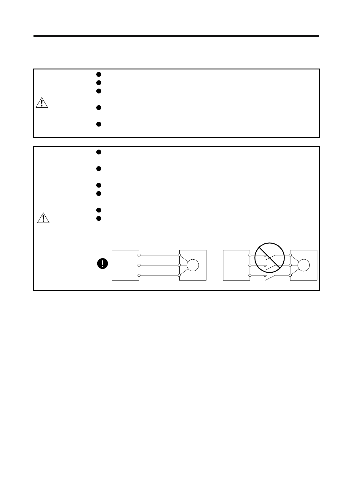
CAUTION
Wire the equipment correctly and securely. Otherwise, the servo motor may operate unexpectedly.
Do not install a power capacitor, surge killer, or radio noise filter (FR-BIF option) on the servo amplifier
output side.
To avoid a malfunction, connect the wires to the correct phase terminals (U, V, and W) of the servo
amplifier and servo motor.
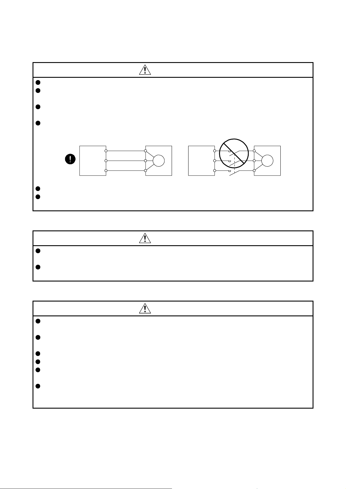
Connect the servo amplifier power output (U, V, and W) to the servo motor power input (U, V, and W)
directly. Do not let a magnetic contactor, etc. intervene. Otherwise, it may cause a malfunction.
Servo amplifier
U
V
W
Do not connect AC power supply directly to the servo motor. Otherwise, it may cause a malfunction.
When the cable is not tightened enough to the terminal block, the cable or terminal block may generate
heat because of the poor contact. Be sure to tighten the cable with specified torque.
Servo motor
U
V
W
Servo motorServo amplifier
U
M
V
W
U
V
W
M
(3) Test run and adjustment
CAUTION
Before operation, check the parameter settings. Improper settings may cause some machines to operate
unexpectedly.
Never make a drastic adjustment or change to the parameter values as doing so will make the operation
unstable.
(4) Usage
CAUTION
When it is assumed that a hazardous condition may occur due to a power failure or product malfunction,
use a servo motor with an external brake to prevent the condition.
Do not scratch the coated surface with hard objects nor clean the coated surface with an organic solvent.
Doing so may scuff the surface.
Do not disassemble, repair, or modify the equipment.
Use the servo amplifier with the specified servo motor.
The electromagnetic brake on the servo motor is designed to hold the motor shaft and should not be
used for ordinary braking.
For such reasons as service life and mechanical structure (e.g. where a ball screw and the servo motor
are coupled via a timing belt), the electromagnetic brake may not hold the motor shaft. To ensure safety,
install a stopper on the machine side.
A - 4
Page 6
(5) Corrective actions
CAUTION
When it is assumed that a hazardous condition may occur due to a power failure or product malfunction,
use a servo motor with an electromagnetic brake or external brake to prevent the condition.
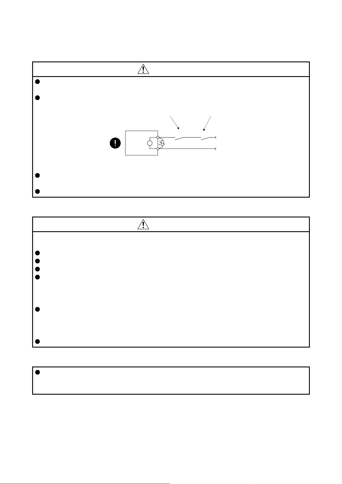
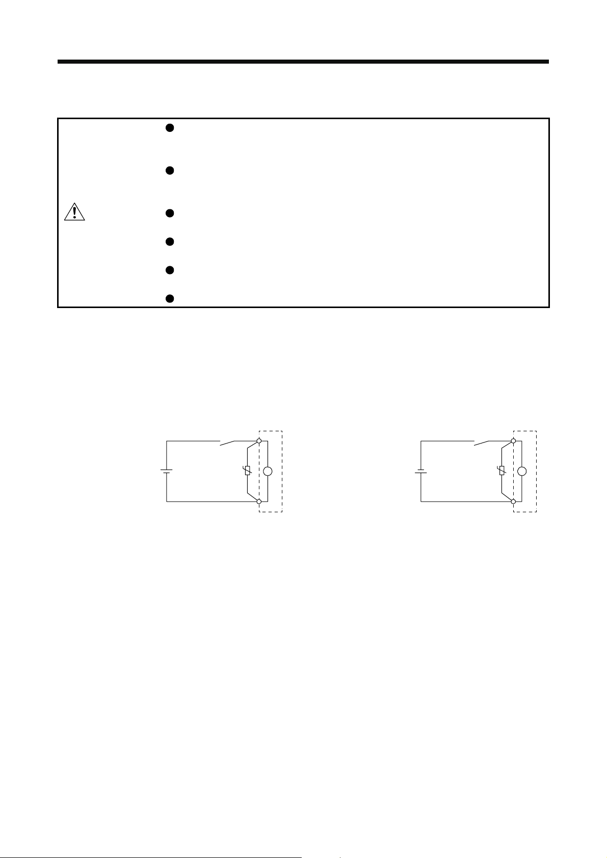
Configure an electromagnetic brake circuit so that it is activated also by an external EMG stop switch.
Contacts must be opened when ALM
(Malfunction) or MBR (Electromagnetic
brake interlock) turns off.
Contacts must be opened
with the EMG stop switch.
Servo motor
B
Electromagnetic brake
When any alarm has occurred, eliminate its cause, ensure safety, and deactivate the alarm before
restarting operation.
Provide an adequate protection to prevent unexpected restart after an instantaneous power failure.
RA
24 V DC
(6) Storage
CAUTION
Note the followings when storing the servo motor for an extended period of time (guideline: three or more
months).
Always store the servo motor indoors in a clean and dry place.
If it is stored in a dusty or damp place, make adequate provision, e.g. cover the whole product.
If the insulation resistance of the winding decreases, check how to store the equipment.
Though the motor is rust-proofed before shipment using paint or rust prevention oil, rust may be
produced depending on the storage conditions or storage period.
If the servo motor is to be stored for longer than six months, apply rust prevention oil again especially to
the machined surfaces of the shaft, etc.
Before using the product after storage for an extended period of time, hand-turn the servo motor output
shaft to confirm that nothing is wrong with the servo motor. When the servo motor is equipped with an
electromagnetic brake, make the above check after releasing the electromagnetic brake with the brake
power supply.
When the product has been stored for an extended period of time, contact your local sales office.
(7) General instruction
To illustrate details, the equipment in the diagrams of this Instruction Manual may have been drawn
without covers and safety guards. When the equipment is operated, the covers and safety guards must
be installed as specified. Operation must be performed in accordance with this Instruction Manual.
A - 5
Page 7
DISPOSAL OF WASTE
Please dispose a servo motor and other options according to your local laws and regulations.
«U.S. customary units»
U.S. customary units are not shown in this manual. Convert the values if necessary according to the
following table.
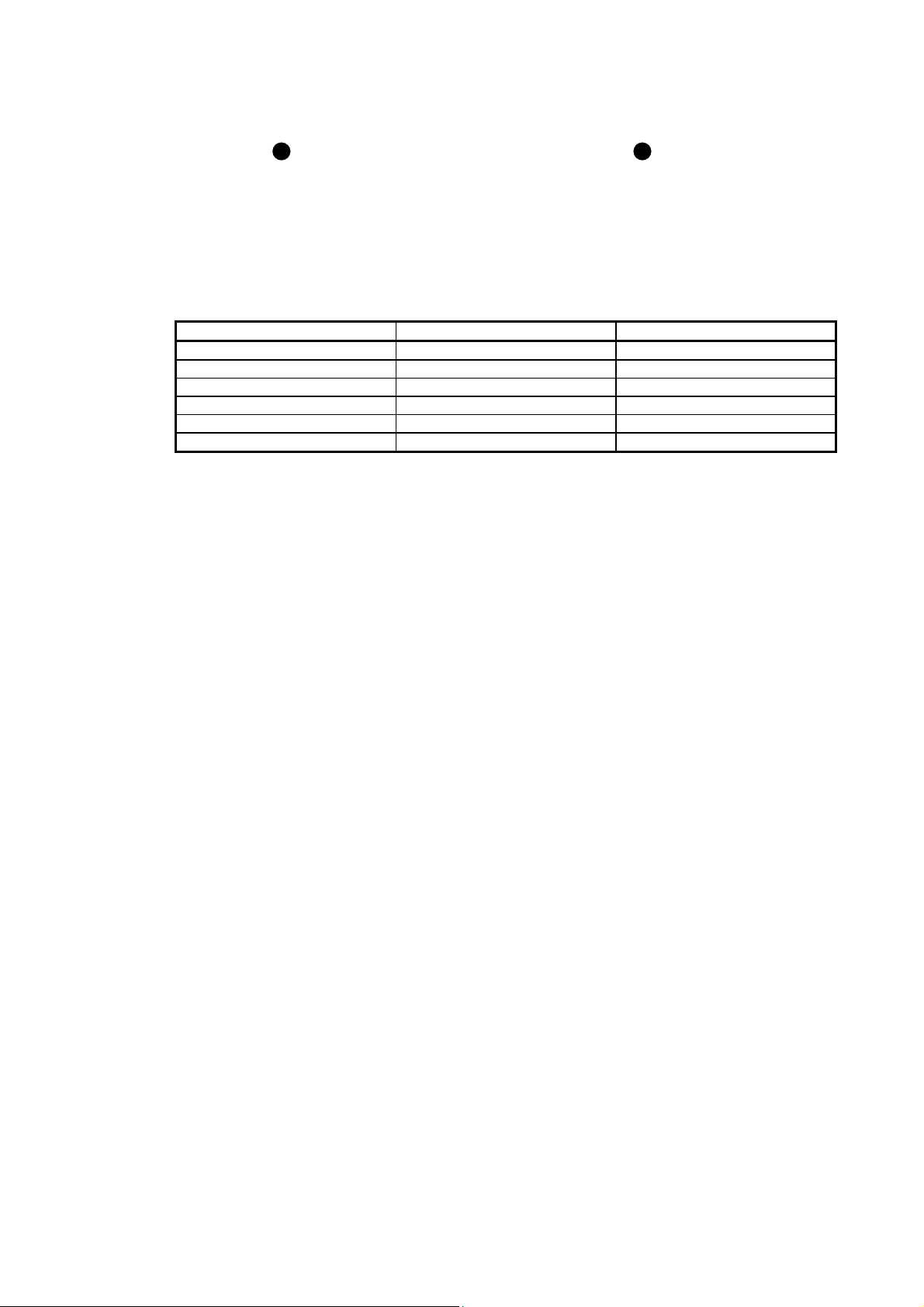
Mass 1 [kg] 2.2046 [lb]
Length 1 [mm] 0.03937 [in]
Torque 1 [N•m] 141.6 [oz•in]
Moment of inertia 1 [(× 10-4 kg•m2)] 5.4675 [oz•in2]
Load (thrust load/axial load) 1 [N] 0.2248 [lbf]
Temperature N [°C] × 9/5 + 32 N [°F]
Quantity SI (metric) unit U.S. customary unit
A - 6
Page 8
CONTENTS
1. INTRODUCTION 1- 1 to 1- 4
1.1 Rating plate....................................................................................................................................... 1- 1
1.2 Parts identification............................................................................................................................. 1- 1
1.3 Electromagnetic brake ...................................................................................................................... 1- 2
1.4 Servo motor shaft shapes................................................................................................................. 1- 4
2. INSTALLATION 2- 1 to 2- 8
2.1 Mounting direction............................................................................................................................. 2- 2
2.2 Load mounting/dismounting precautions.......................................................................................... 2- 3
2.3 Permissible load for the shaft ........................................................................................................... 2- 4
2.4 Protection from oil and water ............................................................................................................ 2- 4
2.5 Cable................................................................................................................................................. 2- 5
2.6 Servo motor with oil seal................................................................................................................... 2- 5
2.7 Inspection items ................................................................................................................................ 2- 6
2.8 Parts having service lives ................................................................................................................. 2- 6
2.9 Machine accuracies .......................................................................................................................... 2- 7
3. CONNECTORS USED FOR SERVO MOTOR WIRING 3- 1 to 3- 6
3.1 Selection of connectors .................................................................................................................... 3- 1
3.2 Wiring connectors (connector configurations A/B/C)........................................................................ 3- 2
3.3 Wiring connectors (connector configurations D/E/F/G) .................................................................... 3- 3
4. CONNECTION OF SERVO AMPLIFIER AND SERVO MOTOR 4- 1 to 4- 8
4.1 Connection instructions .................................................................................................................... 4- 2
4.2 Wiring................................................................................................................................................ 4- 3
4.2.1 HF-KN series servo motor.......................................................................................................... 4- 3
4.2.2 HF-SN series servo motor.......................................................................................................... 4- 5
4.3 Selection example of wires ............................................................................................................... 4- 7
5. WIRING OPTION 5- 1 to 5-22
5.1 Cable/connector sets ........................................................................................................................ 5- 1
5.1.1 Combinations of cable/connector sets....................................................................................... 5- 2
5.1.2 Cable and connector list............................................................................................................. 5- 3
5.2 Encoder cable/connector sets .......................................................................................................... 5- 6
5.3 Servo motor power cable................................................................................................................. 5-17
5.4 Electromagnetic brake cable ........................................................................................................... 5-19
5.5 Wires for option cables .................................................................................................................... 5-20
6. HF-KN SERIES 6- 1 to 6-16
6.1 Model designation............................................................................................................................. 6- 1
6.2 Combination list of servo motors and servo amplifiers ..................................................................... 6- 1
6.3 Standard specifications..................................................................................................................... 6- 2
6.3.1 Standard specifications list......................................................................................................... 6- 2
1
Page 9
6.3.2 Torque characteristics................................................................................................................ 6- 3
6.4 Electromagnetic brake characteristics.............................................................................................. 6- 4
6.5 Servo motors with special shafts ...................................................................................................... 6- 5
6.5.1 Key shaft (with 2 round end key) ............................................................................................... 6- 5
6.5.2 D cut shaft .................................................................................................................................. 6- 5
6.6 Servo motor with oil seal................................................................................................................... 6- 6
6.7 Mounting connectors ........................................................................................................................ 6- 6
6.8 Dimensions ....................................................................................................................................... 6- 8
6.8.1 Standard (without an electromagnetic brake) ............................................................................ 6- 8
6.8.2 With an electromagnetic brake ................................................................................................. 6-12
7. HF-SN SERIES 7- 1 to 7-10
7.1 Model designation............................................................................................................................. 7- 1
7.2 Combination list of servo motors and servo amplifiers ..................................................................... 7- 1
7.3 Standard specifications..................................................................................................................... 7- 2
7.3.1 Standard specifications list......................................................................................................... 7- 2
7.3.2 Torque characteristics................................................................................................................ 7- 3
7.4 Electromagnetic brake characteristics.............................................................................................. 7- 4
7.5 Servo motors with special shafts ...................................................................................................... 7- 5
7.6 Servo motor with oil seal................................................................................................................... 7- 5
7.7 Dimensions ....................................................................................................................................... 7- 6
7.7.1 Standard (without an electromagnetic brake) ............................................................................ 7- 6
7.7.2 With an electromagnetic brake .................................................................................................. 7- 8
APPENDIX App. - 1 to App. - 9
App. 1 Servo motor ID codes ..........................................................................................................App.- 1
App. 2 Manufacturer list ..................................................................................................................App.- 1
App. 3 Compliance with the CE marking......................................................................................... App.- 2
App. 4 Compliance with UL/CSA standard .....................................................................................App.- 3
App. 5 Selection example of servo motor power cable................................................................... App.- 4
App. 6 Connector dimensions .........................................................................................................App.- 5
2
Page 10
1. INTRODUCTION
)
1. INTRODUCTION
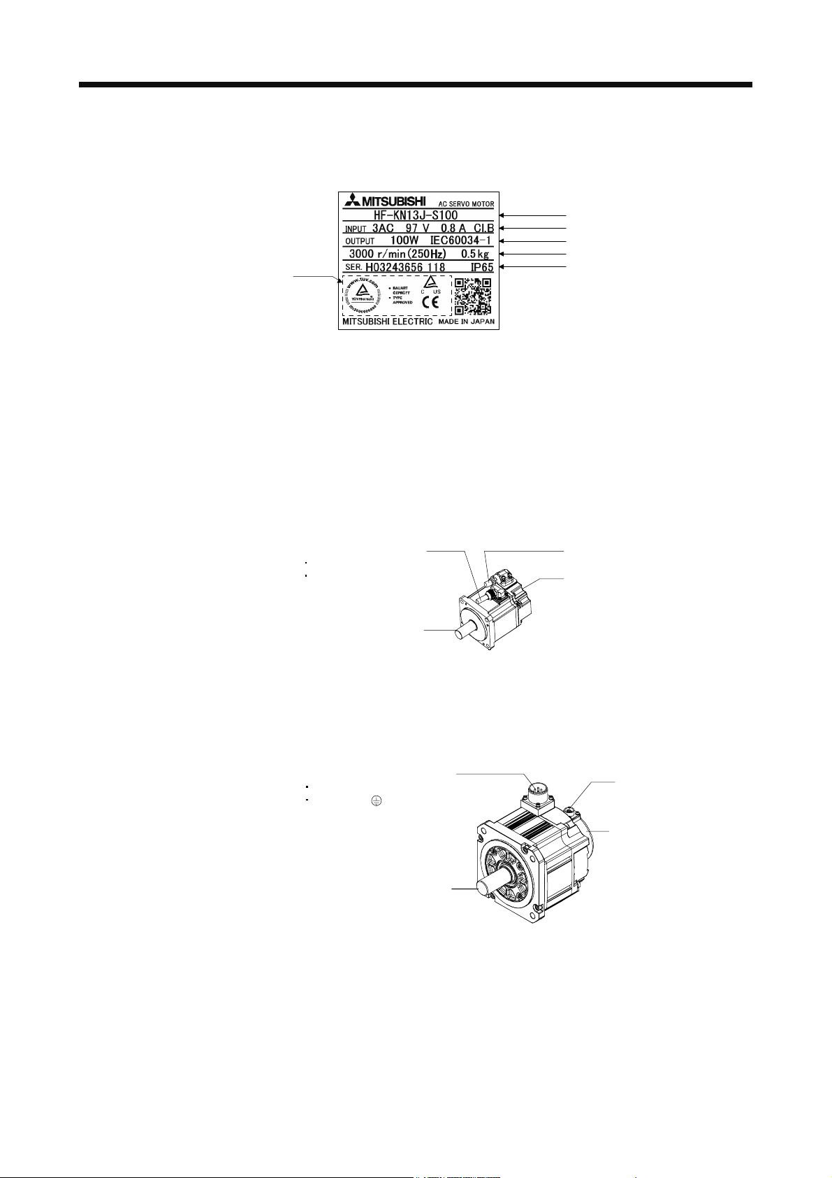
1.1 Rating plate
1.2 Parts identification
Model
Input power and insulation class
Rated output and applied standard
Rated speed and mass
(Note 2)
Note 1. Production year and month of the servo motor are indicated in a serial number on
the rating plate.
The year and month of manufacture are indicated by the last two digits of the year
and one digit of the month [1 to 9, X (10), Y (11), and Z (12)].
For July 2012, the Serial No. is like, "SER. _ _ _ _ _ _ _ _ _ 127".
2. Products approved by Certification Bodies are marked. The marks depends on the
Certification Bodies.
Serial number (Note 1) and IP rating
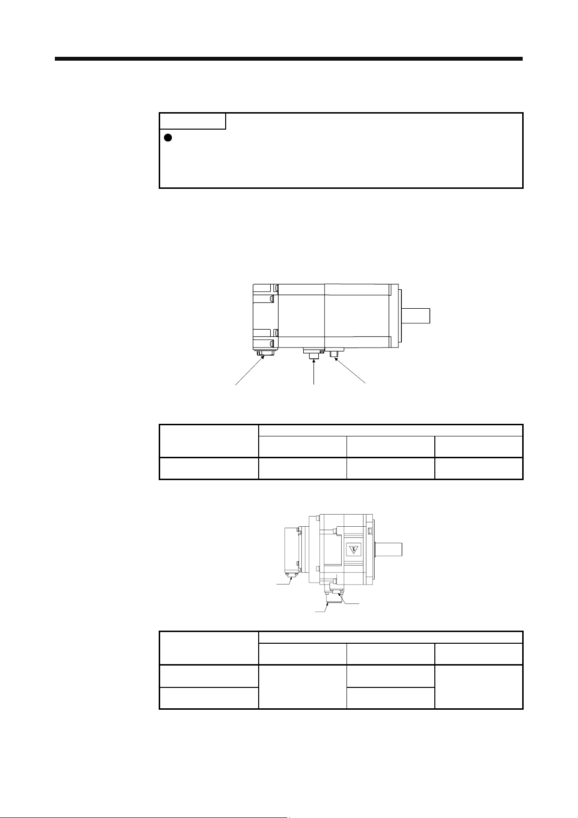
(1) HF-KN series servo motor
(2) HF-SN series servo motor
Power cable (Note 1, 2)
Power lead (U/V/W)
Grounding lead
Encoder cable (Note 1)
Encoder
Servo motor shaft
Note 1. The encoder cable and power supply cable are options.
2. An electromagnetic brake cable is separately required for the servo motor with an
electromagnetic brake.
Power supply connector (Note
Power supply (U/V/W)
Grounding ( )
Encoder connector
Encoder
Servo motor shaft
Note. The servo motor with an electromagnetic brake has the electromagnetic brake
connector separately.
1 - 1
Page 11
1. INTRODUCTION
1.3 Electromagnetic brake
The electromagnetic brake is provided to prevent a drop at a power failure or
servo alarm occurrence during vertical drive or to hold a shaft at a stop. Do not
use it for normal braking (including braking at servo-lock).
The electromagnetic brake has a time lag. Use the electromagnetic brake so that
servo motor control starts after the electromagnetic brake has completely opened.
Be sure to check the operation delay time with a real machine.
Configure an electromagnetic brake circuit so that it is activated also by an
CAUTION
The servo motor with an electromagnetic brake can be used to prevent a drop in vertical lift applications or to
ensure double safety at an emergency stop, for example. When operating the servo motor, supply power to
the electromagnetic brake to release the brake. Switching power off enables the brake.
(1) Electromagnetic brake power supply
Prepare the following power supply for use with the electromagnetic brake only. The electromagnetic
brake terminals (B1 and B2) have no polarity.
24 V DC
power supply for
electromagnetic brake
external EMG stop switch.
For details of the circuit configuration and timing chart, refer to each servo
amplifier instruction manual.
While the electromagnetic brake is opened, the motor may be raised to high
temperature regardless of driving.
The life will be shorten under sudden acceleration/deceleration conditions.
B1
Switch
VAR
B
U
24 V DC
or
power supply for
electromagnetic brake
Switch
VAR
B1
B
U
B2
Electromagnetic brake
The surge absorber (VAR) must be installed between B1 and B2. For the selection and example of
surge absorbers, refer to "Electromagnetic brake characteristic" in the chapter of each servo motor
series.
When you use a diode for a surge absorber, the electromagnetic braking time will be longer.
(2) Sound generation
Though the brake lining may rattle during operation, it poses no functional problem.
If braking sounds, it may be improved by setting the machine resonance suppression filter in the servo
amplifier parameters. For details, refer to each servo amplifier instruction manual.
B2
Electromagnetic brake
1 - 2
Page 12
1. INTRODUCTION
y
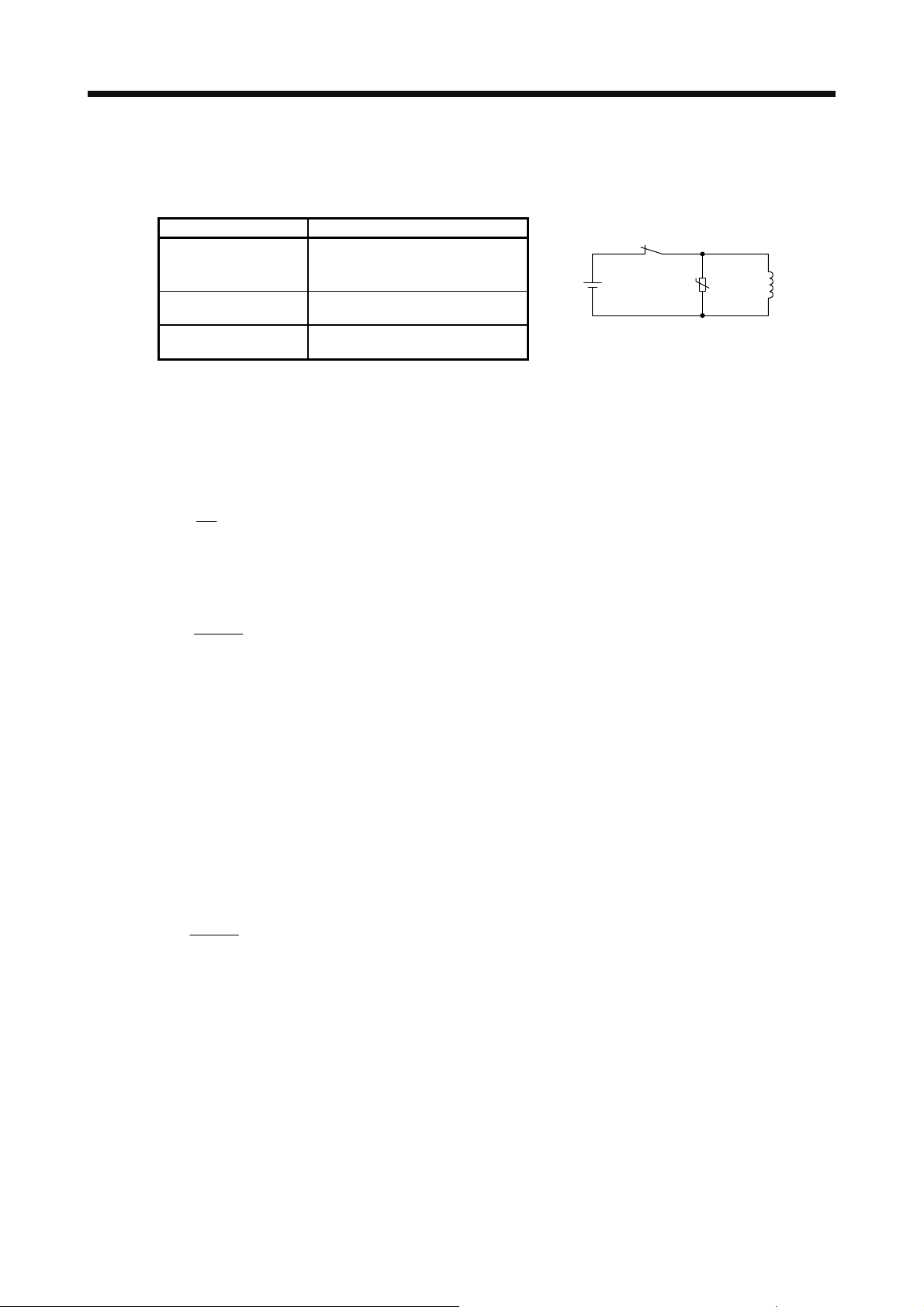
(3) Selection of surge absorbers for electromagnetic brake circuit
The following shows an example how to select a varistor with a surge absorber.
(a) Selection conditions
Electromagnetic brake
specification
Desired suppression
voltage
Durable surge
application time
(b) Tentative selection and verification of surge absorber
1) Maximum allowable circuit voltage of varistor
Tentatively select a varistor whose maximum allowable voltage is larger than Vb [V].
2) Brake current (Ib)
Ib =
3) Energy (E) generated by brake coil
E =
4) Varistor limit voltage (Vi)
From the energy (E) generated in the brake coil and the varister characteristic diagram, calculate
the varistor limit voltage (Vi) when the brake current (Ib) flows into the tentatively selected varistor
during opening of the circuit.
Vi is favorable when the varistor limit voltage (Vi) [V] is smaller than the desired suppressed
voltage (Vs) [V].
If Vi is not smaller than Vs, reselect a varistor or improve the withstand voltage of devices.
5) Surge current width (τ)
Given that the varistor absorbs all energies, the surge current width (τ) will be as follows.
τ =
6) Examining surge life of varister
From the varistor characteristic diagram, find the guaranteed current value (Ip) in which the
number of the surge application life is N at the surge current width (τ). Calculate the guaranteed
current value (Ip) ratio to brake current (Ib).
If an enough margin is ensured for Ip/Ib, the number of the surge application life N [time] can be
considered as favorable.
(4) Others
A leakage magnetic flux will occur at the shaft end of the servo motor equipped with an electromagnetic
brake. Note that chips, screws and other magnetic substances are attracted.
Item Condition
R [Ω]: Resistance
L [H]: Inductance
Vb [V]: Power supply voltage
Vs [V] or less
N times
Vb
[A]
R
2
L × lb
[J]
2
E
Vi × lb
[S]
Rela
24 V DC
U
Varistor
Brake coil
1 - 3
Page 13
1. INTRODUCTION
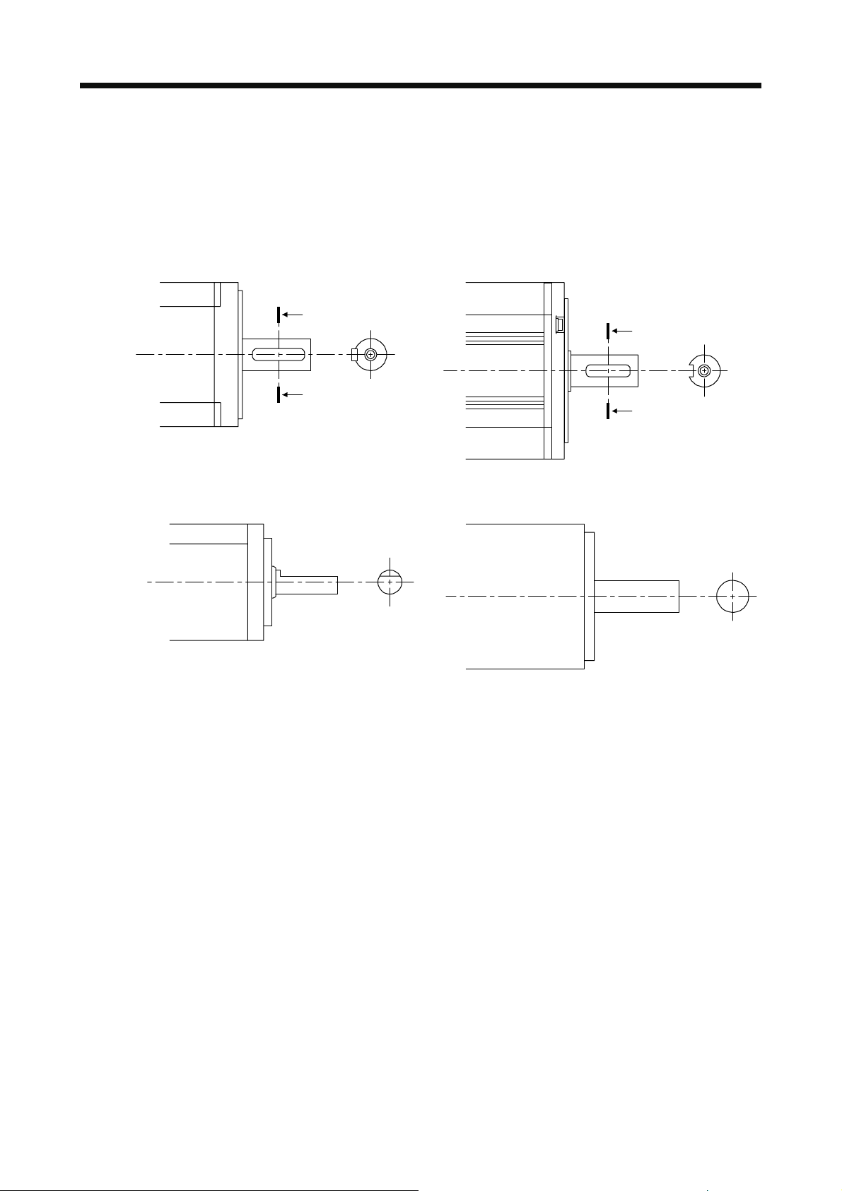
1.4 Servo motor shaft shapes
In addition to the straight shaft, the key shaft and D cut shaft are available as the servo motor shafts.
The key shaft and D cut shaft cannot be used in very frequent start/stop applications.
Since we cannot warrant the servo motor against fracture and similar accidents attributable to a loose key,
use a friction coupling, etc. when coupling the shaft with a machine.
The shaft shape of the standard servo motor changes depending on the series and capacity. Refer to the
chapter of the servo motor series.
A
A
A
Shaft section view AA
A
Shaft section view AA
Key shaft (with 2 round end key) Key shaft (without key)
D cut shaft Straight shaft
1 - 4
Page 14
2. INSTALLATION
2. INSTALLATION
WARNING
CAUTION
To prevent electric shock, ground each equipment securely.
Stacking in excess of the specified number of product packages is not allowed.
Install the equipment on incombustible material. Installing it directly or close to
combustibles will lead to a fire.
Install the servo amplifier and the servo motor in a load-bearing place in
accordance with the Instruction Manual.
Do not get on or put heavy load on the equipment. Otherwise, it may cause injury.
Use the equipment within the specified environment. For the environment, refer to
the specifications of the servo motor series.
Do not drop or strike the servo motor. Isolate it from all impact loads.
Do not install or operate a faulty servo motor.
Do not carry the servo motor by holding the cables, shaft, encoder, or connector.
Otherwise, it may cause a malfunction or injury.
Use the eyebolts of the servo motor to only transport it. Do not use the eyebolts to
transport the servo motor when it is mounted on a machine.
Securely fix the servo motor to the machine. If being attached insecurely, the
motor may come off during operation, leading to injury.
Be sure to measure the motor vibration level with the servo motor mounted on the
machine when checking the vibration level. A great vibration may cause the early
damage of a bearing, encoder, and brake. The great vibration may also cause the
poor connector connection or bolt looseness.
For the gain adjustment at the equipment startup, check the torque waveform and
the speed waveform with a measurement device to check that no vibration
occurs. If the vibration occurs due to high gain, the vibration may cause the early
damage of the servo motor.
Never hit the servo motor or shaft, especially when coupling the servo motor to
the machine. Otherwise, the encoder may malfunction.
When coupling a load to the servo motor, do not use a rigid coupling. Doing so
can cause the shaft to break and the bearing to wear out.
Balance the load to the extent possible. Not doing so can cause vibration during
servo motor operation or damage the bearings and encoder.
Take safety measures, e.g. provide covers, to prevent accidental access to the
rotor of the servo motor during operation.
Do not subject the servo motor shaft to more than the permissible load.
Otherwise, the shaft may break, leading to injury.
When the product has been stored for an extended period of time, contact your
local sales office.
When handling the servo motor, be careful about the edged parts such as the
corners of the servo motor.
2 - 1
Page 15
2. INSTALLATION
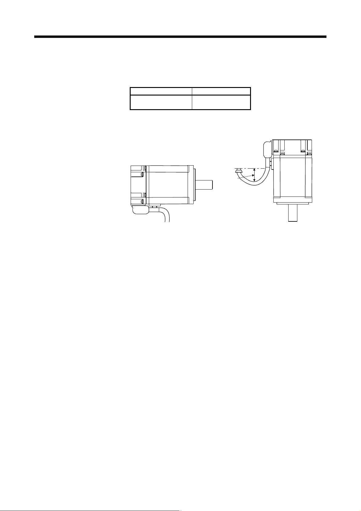
2.1 Mounting direction
(1) Standard servo motor
The following table indicates the mounting direction of the standard servo motor.
For mounting in the horizontal direction, it is recommended to set the connector section downward.
When installing the servo motor vertically or obliquely, provide a connection and trap for the cable.
Servo motor series Mounting direction
HF-KN
HF-SN
May be installed in any
direction.
Cable trap
(2) Servo motor with an electromagnetic brake
The servo motor with an electromagnetic brake can also be installed in the same orientation as the
standard servo motor. When the servo motor with an electromagnetic brake is installed with the shaft
end at top, the brake plate may generate sliding sound but it is not a fault.
2 - 2
Page 16
2. INSTALLATION
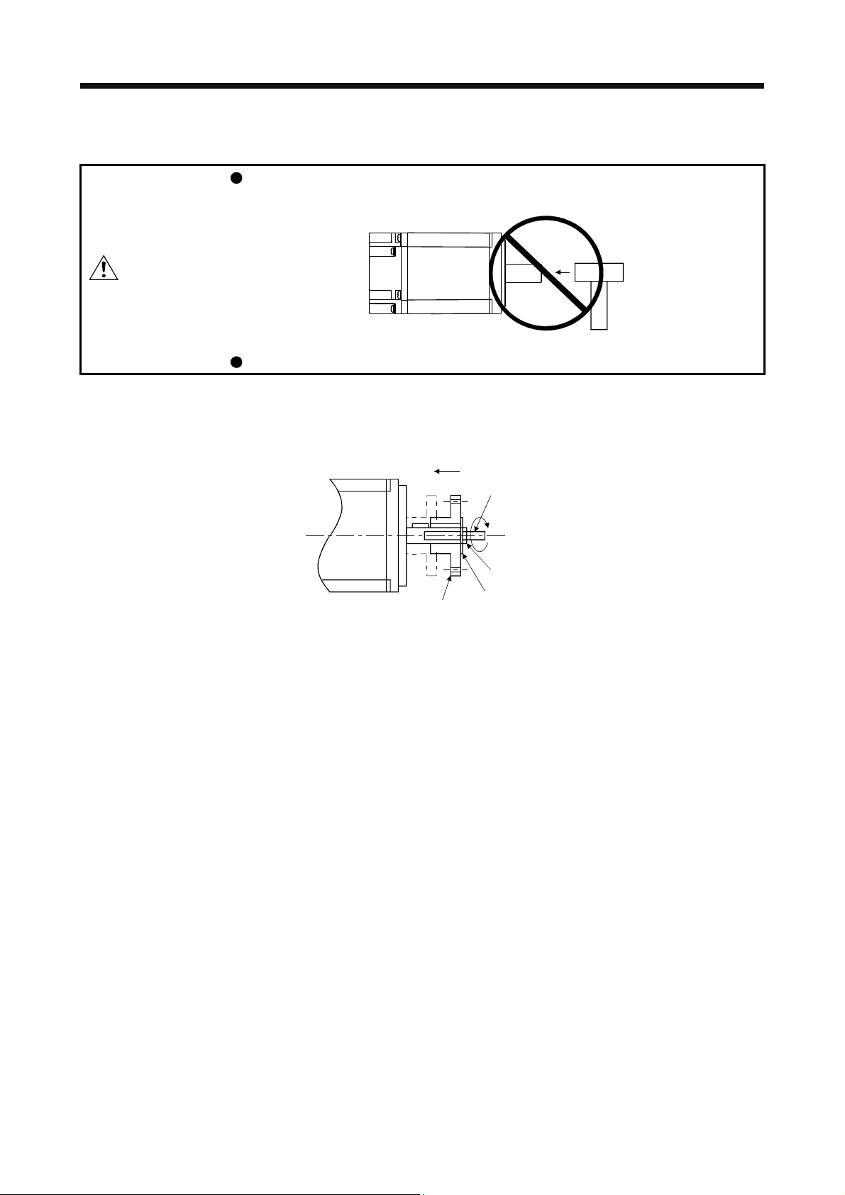
2.2 Load mounting/dismounting precautions
During assembling, the shaft end must not be hammered. Otherwise, the encoder
may malfunction.
CAUTION
Do not process the shaft to avoid damage to the encoder and bearing.
(1) When mounting a pulley to the servo motor with a key shaft, use the screw hole in the shaft end. To fit
the pulley, first insert a double-end stud into the screw hole of the shaft, put a washer against the end
face of the coupling, and insert and tighten a nut to force the pulley in.
Servo motor
Double-end stud
Nut
Pulley
Washer
(2) For the shaft without a key, use a friction coupling or the like.
(3) When removing the pulley, use a pulley remover to protect the shaft from hard load and or impact.
(4) To ensure safety, fit a protective cover or the like on the rotary area, such as the pulley, mounted to the
shaft.
(5) When a threaded shaft end part is needed to mount a pulley on the shaft, please contact your local sales
office.
(6) The direction of the encoder on the servo motor cannot be changed.
(7) When mounting the servo motor, use spring washers, etc. and fully tighten the bolts so that they do not
become loose due to vibration.
2 - 3
Page 17
2. INSTALLATION
2.3 Permissible load for the shaft
CAUTION
For the permissible shaft load specific to the servo motor, refer to the chapter of the servo motor series.
(1) Use a flexible coupling and adjust the misalignment of the shaft to less than the permissible radial load.
(2) When using a pulley, sprocket or timing belt, select a diameter that will fit into the permissible radial load.
(3) Excess of the permissible load can cause the bearing life to reduce and the shaft to break.
(4) The load indicated in this section is static load in a single direction and does not include eccentric load.
Make eccentric load as small as possible. Not doing so can cause the servo motor to be damaged.
2.4 Protection from oil and water
Do not use a rigid coupling as it may apply excessive bending load to the shaft of
the servo motor, leading the shaft to break and the bearing to wear out.
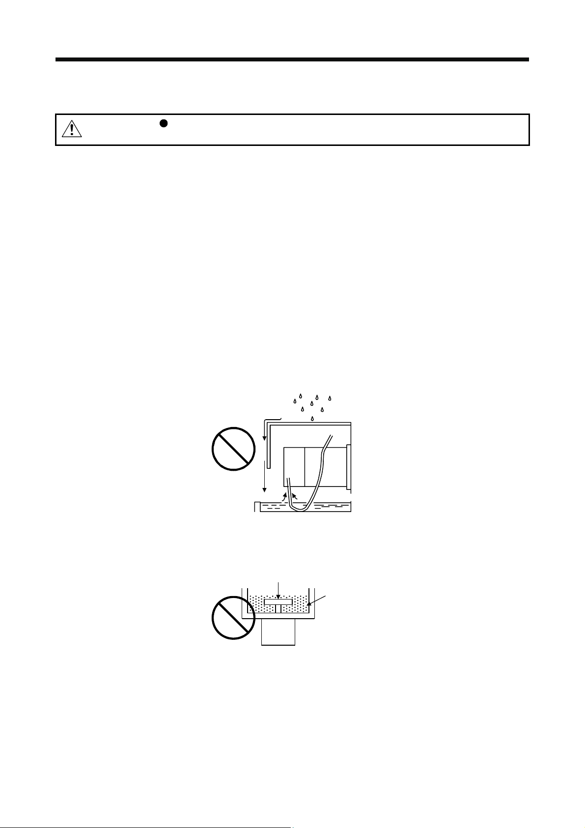
Provide adequate protection to prevent foreign matter, such as oil from entering the servo motor shaft. When
installing the servo motor, consider the items in this section.
(1) Do not use the direct drive motor with its cable soaked in oil or water.
Cover
Servo
motor
Oil/water pool
Capillary phenomenon
(2) When the servo motor is to be installed with the shaft end at top, provide measures so that it is not
exposed to oil and water entering from the machine side, gear box, etc.
Gear
Lubricating oil
Servo motor
(3) If oil such as coolant drops on the servo motor, the sealant, packing, cable and others may be affected
depending on the oil type.
(4) In the environment where the servo motor is exposed to oil mist, oil, water, grease and/or like, a
standard specifications servo motor may not be usable. Please contact your local sales office.
2 - 4
Page 18
2. INSTALLATION
2.5 Cable
The power supply and encoder cables routed from the servo motor should be fixed to the servo motor to
keep them unmovable. Otherwise, the cable may disconnect. In addition, do not modify the connectors,
terminals and others at the ends of the cables.
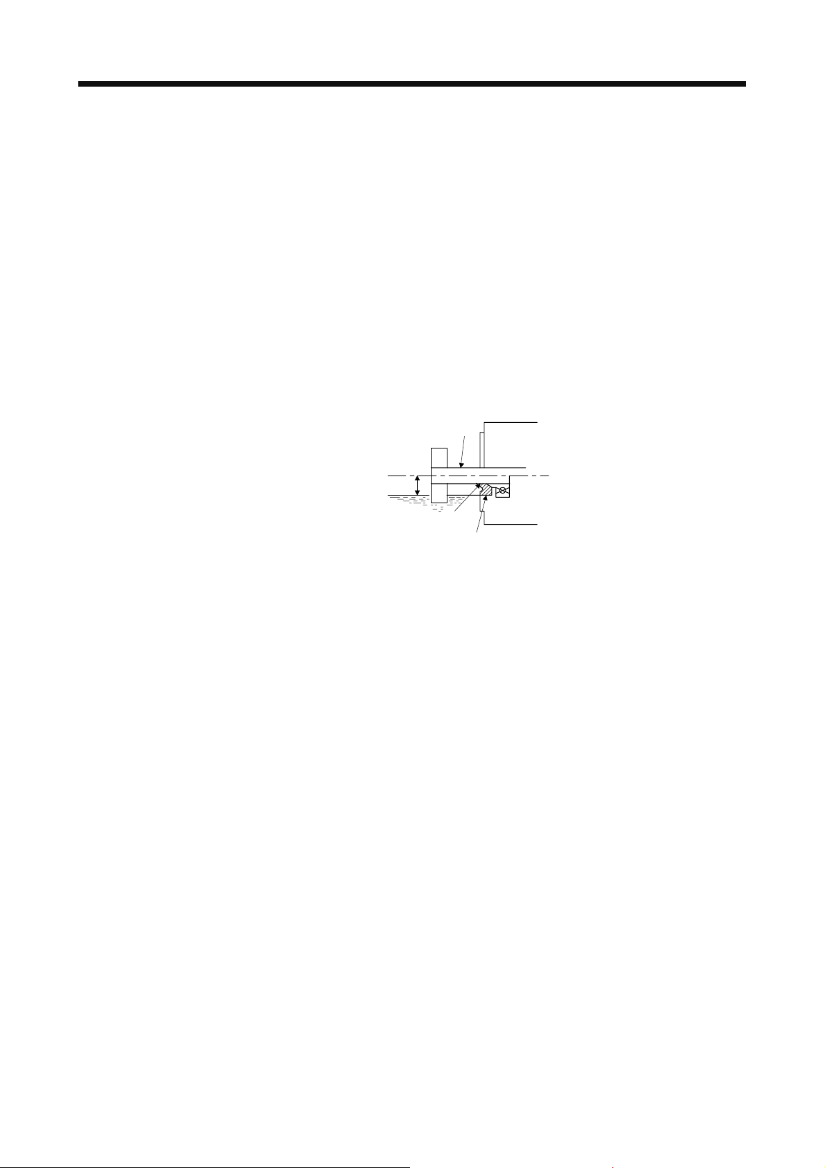
2.6 Servo motor with oil seal
For the servo motor with oil seal, the oil seal prevents the entry of oil into the servo motor. Make sure to
install it according in this section.
The functions have no problem even if the servo motor with oil seal may sound during operation.
(1) Pressure and oil level
Install the servo motor horizontally, and set the oil level in the gear box to be lower than the oil seal lip
always. If the oil level is higher than the oil seal lip, the oil that entered into the servo motor may cause
any failure.
Shaft
Gear
Servo motor
Height above oil level h
Lip
Oil seal
High pressure against the oil seal causes the abrasion and makes the life be short. Keep constant
internal pressure by equipping a ventilator to the gear box.
(2) Temperature
High temperature against the oil seal lip makes the life be short. Avoid exposing the oil seal lip to high
temperature oil since applicable temperature of the material is up to 100 ˚C and temperature of the oil
seal lip rises within 10 ˚C to 15 ˚C at maximum rotation.
2 - 5
Page 19
2. INSTALLATION
2.7 Inspection items
WARNING
Before starting maintenance and/or inspection, turn off the power and wait for 15
minutes or more until the charge lamp turns off. Otherwise, an electric shock may
occur. In addition, when confirming whether the charge lamp is off or not, always
confirm it from the front of the servo amplifier.
To avoid an electric shock, only qualified personnel should attempt inspections.
For repair and parts replacement, contact your local sales office.
CAUTION
It is recommended that the following points periodically be checked.
(1) Check the bearings, brake section, etc. for unusual noise.
(2) Check the cables and the like for scratches or cracks. Especially when the cable is movable, perform
periodic inspections according to operating conditions.
(3) Check the servo motor shaft and coupling for misalignment.
(4) Check the power supply connector and encoder connector tightening screws for looseness.
2.8 Parts having service lives
Service lives of the following parts are listed below. However, the service life vary depending or operating
methods and environment. If any fault is found in the parts, they must be replaced immediately regardless of
their service lives. For parts replacement, please contact your local sales office.
(1) Bearings
When the motor is run at rated speed under rated load, bearings should be exchanged in 20,000 to
30,000 hours as a guideline. This differs on the operating conditions. The bearings must also be
changed if unusual noise or vibration is found during inspection.
(2) Oil seal
Oil seals must be changed in 5,000 hours of operation at rated speed as a guideline. They must also be
changed if oil leakage, etc. is found during inspection.
The functions have no problem even if an oil seal may sound during operation.
Do not disassemble and/or repair the equipment on customer side.
Part name Life guideline
Bearings 20,000 hours to
30,000 hours
Encoder 20,000 hours to
30,000 hours
Oil seal 5000 hours
2 - 6
Page 20
2. INSTALLATION
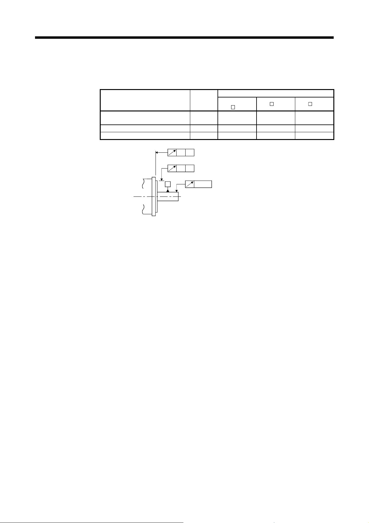
2.9 Machine accuracies
The following table indicates the machine accuracies of the servo motor around the output shaft and
mounting. (except the optional products)
Accuracy [mm]
Runout of flange surface to output
shaft
Runout of fitting OD of flange surface b) 0.04 0.04 0.06
Runout of output shaft end c) 0.02 0.02 0.03
Measuring
position
a) 0.05 0.06 0.08
Less than
100
a)
A
b)
A
A
c)
Flange size
130 176
2 - 7
Page 21
2. INSTALLATION
MEMO
2 - 8
Page 22
3. CONNECTORS USED FOR SERVO MOTOR WIRING
r
3. CONNECTORS USED FOR SERVO MOTOR WIRING
POINT
The IP rating indicated is the connector's protection against ingress of dust and
water when the connector is connected to a servo amplifier or servo motor. If the
IP rating of the connector, servo amplifier and servo motor vary, the overall IP
rating depends on the lowest IP rating of all components.
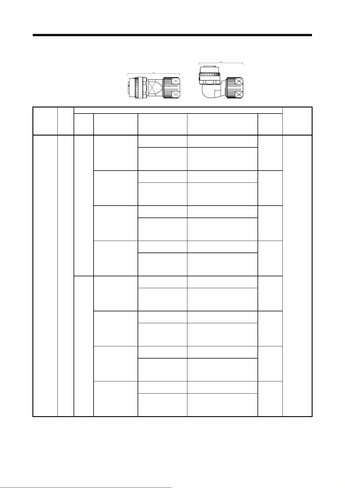
3.1 Selection of connectors
Use the connector configuration products given in the table as the connectors for connection with the servo
motor. Refer to section 3.2 and 3.3 for the compatible connector configuration products.
(1) HF-KN series
Encoder connecto
Electromagnetic
brake connector
Power supply connector
(2) HF-SN series
Servo motor
HF-KN_
Encoder connector
Power supply connector
Servo motor
HF-SN52/HF-SN102/
HF-SN152
HF-SN202/HF-SN302
Wiring connector
For encoder For power supply
Connector
configuration A
Connector
configuration B
For electromagnetic
brake
Connector
configuration C
Electromagnetic brake connector
Wiring connector
For encoder For power supply
Connector
Connector
configuration D
configuration E
Connector
configuration G
For electromagnetic
brake
Connector
configuration F
3 - 1
Page 23
3. CONNECTORS USED FOR SERVO MOTOR WIRING
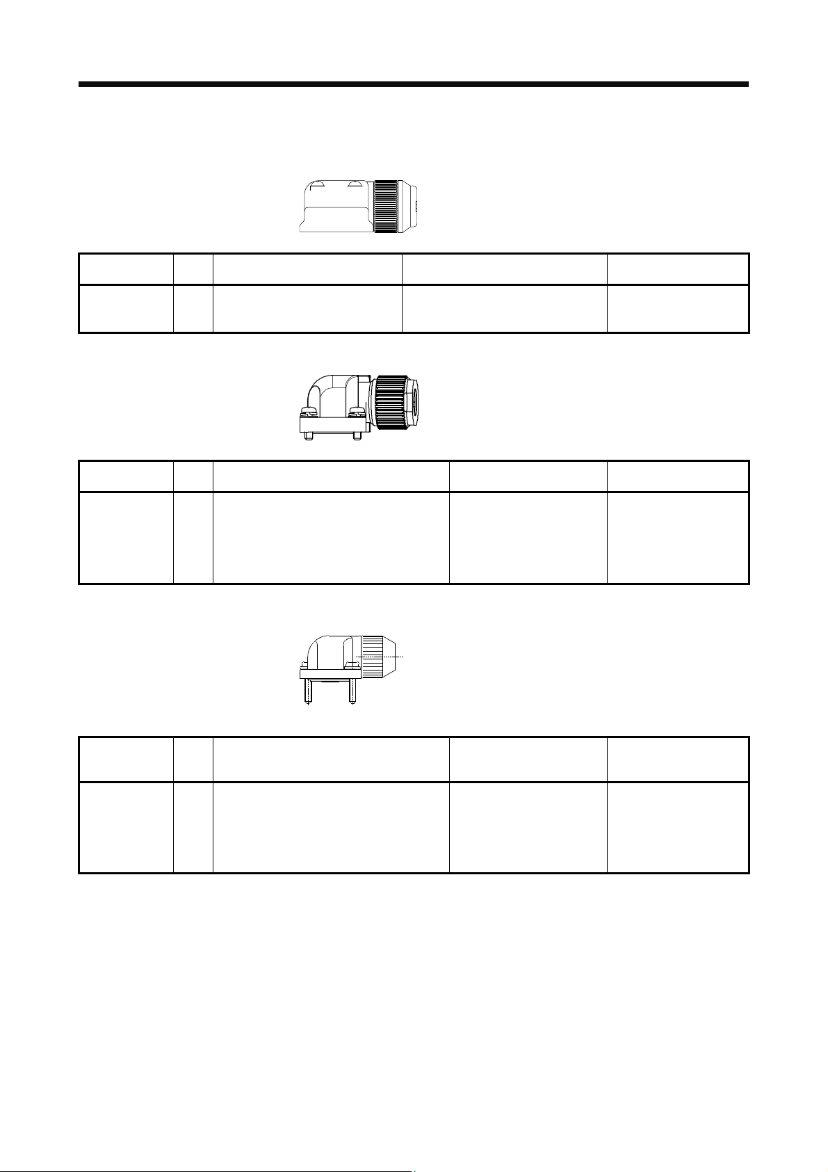
3.2 Wiring connectors (connector configurations A/B/C)
The connectors in this section comply with UL/CSA standards.
Connector
configuration
A (for encoder) IP65
Feature
Connector: 2174053-1
(TE Connectivity)
Note. The connector to be mated.
Connector
configuration
B (for power
supply)
Feature
Connector: KN4FT04SJ1-R
IP65
Contact: ST-TMH-S-C1B-100 (A534G)
Note. The connector to be mated.
Connector Crimping tool
For ground clip: 1596970-1
For receptacle contact: 1596847-1
(TE Connectivity)
Servo motor encoder
1674339-1
(TE Connectivity)
Connector Crimping tool
HOOD/SOCKET
INSULATOR/BUSHING/
GROUND NUT
(JAE)
CT160-3-TMH5B
(JAE)
Servo motor power supply
JN4AT04NJ1
(JAE)
connector (Note)
connector (Note)
Connector
configuration
C
(for
electromagnetic
brake)
Feature
Connector: JN4FT02SJ1-R
IP65
Contact: ST-TMH-S-C1B-100 (A534G)
Note. The connector to be mated.
Connector Crimping tool
HOOD/SOCKET
INSULATOR/BUSHING/
GROUND NUT
(JAE)
Servo motor
CT160-3-TMH5B
(JAE)
electromagnetic brake
connector (Note)
JN4AT02PJ1
(JAE)
3 - 2
Page 24
3. CONNECTORS USED FOR SERVO MOTOR WIRING
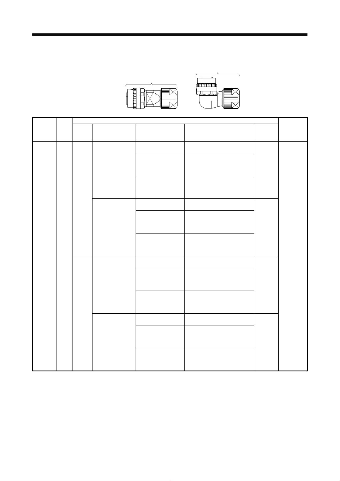
3.3 Wiring connectors (connector configurations D/E/F/G)
Angle plug
Straight plug
(one-touch connection type)
(one-touch connection type)
Connector
configuration
(for encoder)
Feature
D
IP67
Type Plug Socket contact Contact shape
CMV1-SP10S-M1
(one-touch connection
type)
Straight
CMV1-SP10S-M2
(one-touch connection
type)
CMV1-AP10S-M1
(one-touch connection
type)
Angle
CMV1-AP10S-M2
(one-touch connection
type)
Note. The connector to be mated.
Plug (DDK)
CMV1-#22ASC-S1-100
CMV1-#22ASC-C1-100
CMV1-#22ASC-C2-100
CMV1-#22ASC-S1-100
CMV1-#22ASC-C1-100
CMV1-#22ASC-C2-100
CMV1-#22ASC-S1-100
CMV1-#22ASC-C1-100
CMV1-#22ASC-C2-100
CMV1-#22ASC-S1-100
CMV1-#22ASC-C1-100
CMV1-#22ASC-C2-100
Soldering type
Applicable wire size: AWG 20 or less
Crimping type
Applicable wire size: AWG 24 to 20
The crimping tool (357J-53162T) is
required.
Crimping type
Applicable wire size: AWG 28 to 24
The crimping tool (357J-53163T) is
required.
Soldering type
Applicable wire size: AWG 20 or less
Crimping type
Applicable wire size: AWG 24 to 20
The crimping tool (357J-53162T) is
required.
Crimping type
Applicable wire size: AWG 28 to 24
The crimping tool (357J-53163T) is
required.
Soldering type
Applicable wire size: AWG 20 or less
Crimping type
Applicable wire size: AWG 24 to 20
The crimping tool (357J-53162T) is
required.
Crimping type
Applicable wire size: AWG 28 to 24
The crimping tool (357J-53163T) is
required.
Soldering type
Applicable wire size: AWG 20 or less
Crimping type
Applicable wire size: AWG 24 to 20
The crimping tool (357J-53162T) is
required.
Crimping type
Applicable wire size: AWG 28 to 24
The crimping tool (357J-53163T) is
required.
Cable OD
[mm]
(reference)
5.5 to 7.5
7.0 to 9.0
5.5 to 7.5
7.0 to 9.0
Servo motor
encoder
connector
(Note)
CM10-R10P
3 - 3
Page 25
3. CONNECTORS USED FOR SERVO MOTOR WIRING
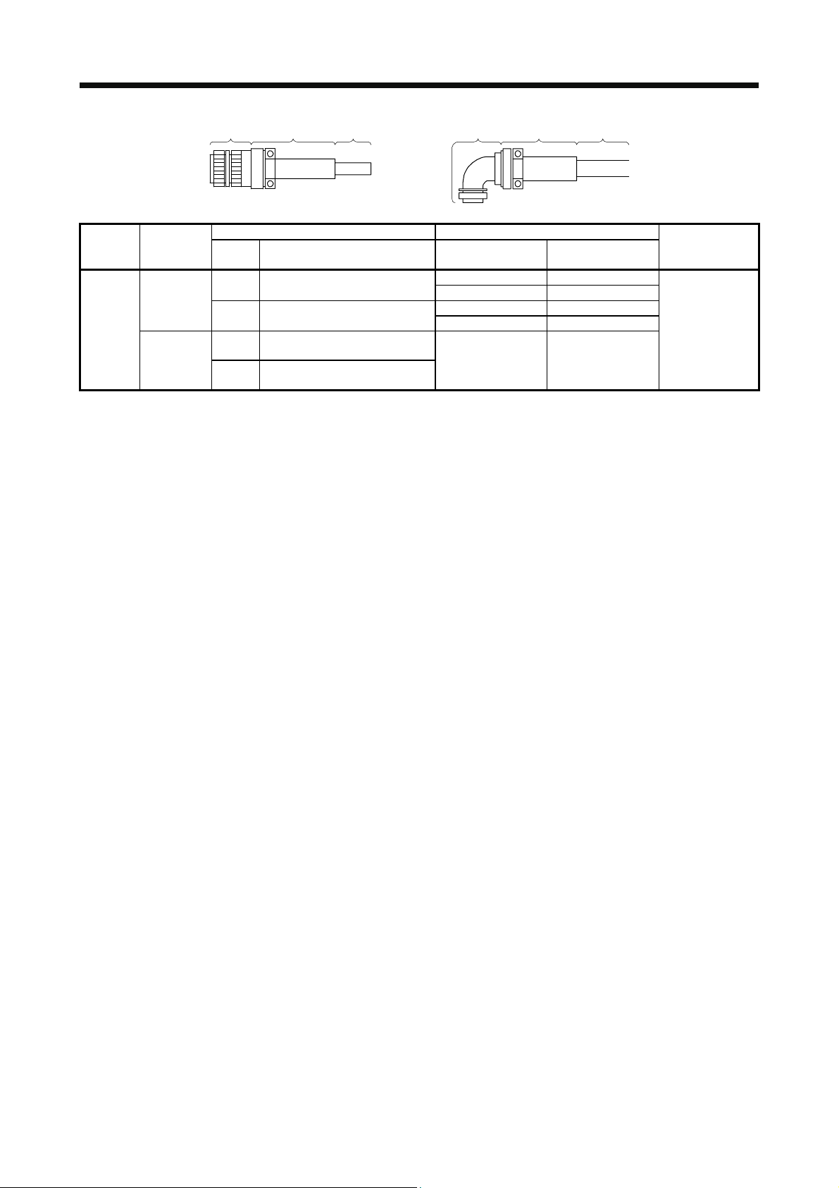
Plug Cable clamp Cable Plug Cable clamp Cable
Connector
configuration
E
(for power
supply)
Feature
IP67
EN compliant
(Note 1)
General
environment
Type Model
Straight
Angle
Straight
Angle
Note 1. Not comply with EN.
2. The connector to be mated.
Plug (DDK) Cable clamp (DDK)
Cable OD
[mm] (reference)
CE05-6A18-10SD-D-BSS
Applicable wire size: AWG 14 to 12
CE05-8A18-10SD-D-BAS
Applicable wire size: AWG 14 to 12
D/MS3106B18-10S
Applicable wire size: AWG 14 to 12
D/MS3108B18-10S
Applicable wire size: AWG 14 to 12
8.5 to 11 CE3057-10A-2-D
10.5 to 14.1 CE3057-10A-1-D
8.5 to 11 CE3057-10A-2-D
10.5 to 14.1 CE3057-10A-1-D
14.3 or less
(bushing ID)
Model
D/MS3057-10A
Servo motor power
supply connector
(Note 2)
MS3102A18-10P
3 - 4
Page 26
3. CONNECTORS USED FOR SERVO MOTOR WIRING
Connector
configuration
(for
electromag
netic
brake)
Feature
F
IP67
Type Plug Socket contact Contact shape
CMV1-SP2S-S
(one-touch connection
type)
CMV1-SP2S-M1
(one-touch connection
type)
Straight
CMV1-SP2S-M2
(one-touch connection
type)
CMV1-SP2S-L
(one-touch connection
type)
CMV1-AP2S-S
(one-touch connection
type)
CMV1-AP2S-M1
(one-touch connection
type)
Angle
CMV1-AP2S-M2
(one-touch connection
type)
CMV1-AP2S-L
(one-touch connection
type)
Note. The connector to be mated.
Straight plug
(one-touch connection type)
Plug (DDK)
CMV1-#22BSC-S2-100
CMV1-#22BSC-C3-100
CMV1-#22BSC-S2-100
CMV1-#22BSC-C3-100
CMV1-#22BSC-S2-100
CMV1-#22BSC-C3-100
CMV1-#22BSC-S2-100
CMV1-#22BSC-C3-100
CMV1-#22BSC-S2-100
CMV1-#22BSC-C3-100
CMV1-#22BSC-S2-100
CMV1-#22BSC-C3-100
CMV1-#22BSC-S2-100
CMV1-#22BSC-C3-100
CMV1-#22BSC-S2-100
CMV1-#22BSC-C3-100
(one-touch connection type)
Angle plug
Soldering type
Applicable wire size: AWG 16 or less
Crimping type
Applicable wire size: AWG 20 to 16
The crimping tool (357J-53164T) is
required.
Soldering type
Applicable wire size: AWG 16 or less
Crimping type
Applicable wire size: AWG 20 to 16
The crimping tool (357J-53164T) is
required.
Soldering type
Applicable wire size: AWG 16 or less
Crimping type
Applicable wire size: AWG 20 to 16
The crimping tool (357J-53164T) is
required.
Soldering type
Applicable wire size: AWG 16 or less
Crimping type
Applicable wire size: AWG 20 to 16
The crimping tool (357J-53164T) is
required.
Soldering type
Applicable wire size: AWG 16 or less
Crimping type
Applicable wire size: AWG 20 to 16
The crimping tool (357J-53164T) is
required.
Soldering type
Applicable wire size: AWG 16 or less
Crimping type
Applicable wire size: AWG 20 to 16
The crimping tool (357J-53164T) is
required.
Soldering type
Applicable wire size: AWG 16 or less
Crimping type
Applicable wire size: AWG 20 to 16
The crimping tool (357J-53164T) is
required.
Soldering type
Applicable wire size: AWG 16 or less
Crimping type
Applicable wire size: AWG 20 to 16
The crimping tool (357J-53164T) is
required.
Cable OD
[mm]
(reference)
4.0 to 6.0
5.5 to 7.5
7.0 to 9.0
9.0 to 11.6
4.0 to 6.0
5.5 to 7.5
7.0 to 9.0
9.0 to 11.6
Servo motor
electromagnetic
brake
connector
(Note)
CM10-R2P
3 - 5
Page 27

3. CONNECTORS USED FOR SERVO MOTOR WIRING
Plug Cable clamp Cable Plug Cable clamp Cable
Connector
configuration
G
(for power
supply)
Feature
IP67
EN compliant
(Note 1)
General
environment
Type Model
Straight
Angle
Straight
Angle
Note 1. Not comply with EN.
2. The connector to be mated.
Plug (DDK) Cable clamp (DDK)
Cable OD
[mm] (reference)
CE05-6A22-22SD-D-BSS
Applicable wire size: AWG 10 to 8
CE05-8A22-22SD-D-BAS
Applicable wire size: AWG 10 to 8
D/MS3106B22-22S
Applicable wire size: AWG 10 to 8
D/MS3108B22-22S
Applicable wire size: AWG 10 to 8
9.5 to 13 CE3057-12A-2-D
12.5 to 16 CE3057-12A-1-D
9.5 to 13 CE3057-12A-2-D
12.5 to 16 CE3057-12A-1-D
15.9 or less
(bushing ID)
Model
D/MS3057-12A
Servo motor power
supply connector
(Note 2)
MS3102A22-22P
3 - 6
Page 28
4. CONNECTION OF SERVO AMPLIFIER AND SERVO MOTOR
4. CONNECTION OF SERVO AMPLIFIER AND SERVO MOTOR
Any person who is involved in wiring should be fully competent to do the work.
Ground the servo motor securely.
Do not attempt to wire the servo motor until it has been mounted. Otherwise, it
WARNING
CAUTION
may cause an electric shock.
The cables should not be damaged, stressed, loaded, or pinched. Otherwise, it
may cause an electric shock.
To avoid an electric shock, insulate the connections of the power supply
terminals.
Wire the equipment correctly and securely. Otherwise, the servo motor may
operate unexpectedly, resulting in injury.
Connect cables to the correct terminals. Otherwise, a burst, damage, etc. may
occur.
Ensure that polarity (+/-) is correct. Otherwise, a burst, damage, etc. may occur.
Do not install a power capacitor, surge killer or radio noise filter (FR-BIF option)
with the power line of the servo motor.
Do not modify the equipment.
Connect the servo amplifier power output (U, V, and W) to the servo motor power
input (U, V, and W) directly. Do not let a magnetic contactor, etc. intervene.
Otherwise, it may cause a malfunction.
Servo amplifier
U
V
W
Servo motor
U
V
W
Servo motorServo amplifier
U
M
V
W
U
V
M
W
4 - 1
Page 29
4. CONNECTION OF SERVO AMPLIFIER AND SERVO MOTOR
4.1 Connection instructions
To avoid a malfunction, connect the wires to the correct phase terminals (U, V,
and W) of the servo amplifier and servo motor.
Do not connect AC power supply directly to the servo motor. Otherwise, it may
cause a malfunction.
CAUTION
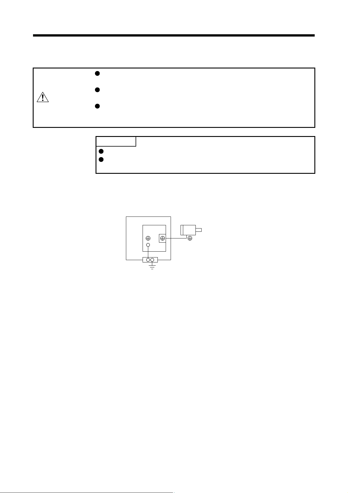
For grounding, connect the grounding lead wire from the servo motor to the protective earth (PE) terminal of
the servo amplifier, and then connect the wire from the servo amplifier to the ground via the protective earth
of the cabinet. Do not connect the wire directly to the protective earth of the cabinet.
Do not use the 24 V DC interface power supply for the electromagnetic brake.
Always use the power supply designed exclusively for the electromagnetic brake.
Otherwise, it may cause a malfunction.
POINT
Refer to chapter 5 for the selection of the encoder cable.
Refer to the chapter of the servo motor series for the selection of a surge
absorber for the electromagnetic brake.
Cabinet
Servo motorServo amplifier
PE
terminal
(Note)
Note. The number of PE terminals of the servo amplifier differs depending on the amplifier
types.
4 - 2
Page 30

4. CONNECTION OF SERVO AMPLIFIER AND SERVO MOTOR
4.2 Wiring
To wire to the servo amplifier, use connectors packed with the amplifier or optional connectors. For servo
amplifier terminals, refer to each servo amplifier instruction manual.
4.2.1 HF-KN series servo motor
(1) Servo motor power supply cable wiring diagrams
(a) When cable length is 10 m or less
10 m or less
MR-PWS1CBL_M-A1-L
MR-PWS1CBL_M-A2-L
(Note) CNP2
U
V
MR-PWS1CBL_M-A1-H
MR-PWS1CBL_M-A2-H
(Red)
(White)
(Black)
(Green/yellow)
Servo motorServo amplifier
U
V
WW
M
(b) When cable length exceeds 10 m
When the cable length exceeds 10 m, fabricate an extension cable as shown below. In this case, the
motor power supply cable should be within 2 m.
Refer to section 4.3 for the wire used for the extension cable.
(Note 1) CNP2
U
V
Note 1. The name and shape of connector differ depending on the servo amplifier types.
2. Use of the following connectors is recommended when ingress protection (IP65) is necessary.
Note. The name and shape of connector differ depending on the servo amplifier types.
50 m or less 2 m or less
Extension cable
(Note 2)
a) Junction connector for
extension cable
MR-PWS1CBL2M-A1-L
MR-PWS1CBL2M-A2-L
MR-PWS1CBL2M-A1-H
MR-PWS1CBL2M-A2-H
MR-PWS2CBL03M-A1-L
MR-PWS2CBL03M-A2-L
(Red)
(White)
(Black)
(Green/yellow)
(Note 2)
b) Junction connector for
motor power supply cable
Servo motorServo amplifier
U
V
WW
M
Junction connector
a) Junction connector for
extension cable
b)
Junction connector for
motor power supply cable
Connector: RM15WTPZ-4P(71)
Cord clamp: JR13WCC-5(72)
(Hirose Electric)
Connector: RM15WTJZ-4S(71)
Cord clamp: JR13WCC-8(72)
(Hirose Electric)
Description IP rating
IP65
Numeral changes depending on the cable OD.
IP65
Numeral changes depending on the cable OD.
4 - 3
Page 31

4. CONNECTION OF SERVO AMPLIFIER AND SERVO MOTOR
(2) Electromagnetic brake cable wiring diagrams
(a) When cable length is 10 m or less
10 m or less
MR-BKS1CBL_M-A1-L
MR-BKS1CBL_M-A2-L
(Note 3)
24 V DC power supply
for electromagnetic
brake
Note 1. Connect a surge absorber as close to the servo motor as possible.
2. There is no polarity in electromagnetic brake terminals (B1 and B2).
3. Do not use the 24 V DC interface power supply for the electromagnetic brake.
4. Create the circuit in order to shut off by interlocking with the emergency stop switch.
(Electromagnetic
brake interlock)
When fabricating the electromagnetic brake cable MR-BKS1CBL-_M-H, refer to section 5.4 and
section 5.5.
(b) When cable length exceeds 10 m
When the cable length exceeds 10 m, fabricate an extension cable as shown below. In this case, the
electromagnetic brake cable should be within 2 m.
Refer to section 4.3 for the wire used for the extension cable.
(Note 5)
24 V DC power supply
for electromagnetic
brake
(Electromagnetic
brake interlock)
MBR
MBR
ALM
(Malfunction)
50 m or less
Extension cable
(To be fabricated)
ALM
(Malfunction)
(Note 4)
(Note 1)
(Note 3)
(Note 1)
MR-BKS1CBL_M-A1-H
MR-BKS1CBL_M-A2-H
U
MR-BKS1CBL2M-A1-L
MR-BKS1CBL2M-A2-L
MR-BKS1CBL2M-A1-H
MR-BKS1CBL2M-A2-H
MR-BKS2CBL03M-A1-L
MR-BKS2CBL03M-A2-L
U
AWG 20
AWG 20
2 m or less
AWG 20
AWG 20
Servo motor
(Note 2)
B1
B
B2
Servo motor
(Note 4)
B1
B
B2
(Note 2)
a) Junction connector for
extension cable
Note 1. Connect a surge absorber as close to the servo motor as possible.
2. Use of the following connectors is recommended when ingress protection (IP65) is necessary.
(Note 2)
b) Junction connector for
electromagnetic brake cable
Junction connector Description IP rating
a)
Junction connector for
extension cable
b)
Junction connector for
electromagnetic brake cable
3. Create the circuit in order to shut off by interlocking with the emergency stop switch.
4. There is no polarity in electromagnetic brake terminals (B1 and B2).
5. Do not use the 24 V DC interface power supply for the electromagnetic brake.
CM10-CR2P- (DDK)
Wire size: S, M, L
CMV1-SP2S- (DDK)
Wire size: S, M1, M2, L
IP65
IP65
4 - 4
Page 32

4. CONNECTION OF SERVO AMPLIFIER AND SERVO MOTOR
4.2.2 HF-SN series servo motor
Refer to section 4.3 for the wires used for wiring.
(1) Wiring
50 m or less
(Note 4) CNP2
U
V
W
Servo motorServo amplifier
U
V
W
M
(Note 2)
24 V DC power supply
for electromagnetic
brake
Note 1. There is no polarity in electromagnetic brake terminals (B1 and B2).
2. Do not use the 24 V DC interface power supply for the electromagnetic brake.
3. Create the circuit in order to shut off by interlocking with the emergency stop switch.
4. The name and shape of connector differ depending on the servo amplifier types.
MBR
(Electromagnetic
brake interlock)
RA2
ALM
(Malfunction)
RA1
(Note 3)
RA3
B1
U
B2
B
(Note 1)
4 - 5
Page 33

4. CONNECTION OF SERVO AMPLIFIER AND SERVO MOTOR
(2) Connector
The connector fitting the servo motor is prepared as optional equipment. Refer to section 5 for details of
the options. For types other than those prepared as optional equipment, refer to chapter 3.
Servo motor
HF-SN52/HF-SN102/
HF-SN152
HF-SN202/HF-SN302
Encoder Power
CM10-R10P
(DDK)
The followings show the encoder connector, power connector, and electromagnetic brake connector
viewed from the connection side.
Encoder connector
CM10-R10P
Power supply connector
MS3102A18-10P
MS3102A22-22P
Terminal
7
10
9
8
3
6
2
5
1
4
No.
1 MR A U
2 MRR B V
3 C W
4
5 LG
6
7
8 P5
9
10 SHD
Signal
CD
AB
Terminal
No.
D
Servo motor-side connectors
MS3102A18-10P
MS3102A22-22P
Electromagnetic brake connector
Signal
(PE)
Electromagnetic
CM10-R2P
Terminal
No.
12
1
2
Note. For the motor
brake
CM10-R2P
(DDK)
with an
electromagnetic
brake, supply
electromagnetic
brake power
(24 V DC).
There is no
polarity.
Signal
(Note)
B1
(Note)
B2
4 - 6
Page 34

4. CONNECTION OF SERVO AMPLIFIER AND SERVO MOTOR
4.3 Selection example of wires
POINT
Wires indicated in this section are separated wires. When using a cable for
power line (U, V, and W) between the servo amplifier and servo motor, use a
600 V grade EP rubber insulated chloroprene sheath cab-tire cable (2PNCT).
For selection of cables, refer to appendix 6.
To comply with the UL/CSA standard, use the wires shown in appendix 4 for
wiring. To comply with other standards, use a wire that is complied with each
standard.
Selection condition of wire size is as follows.
Construction condition: One wire is constructed in the air.
Wire length: 30 m or less
The following diagram shows the wires used for wiring. Use the wires given in this section or equivalent.
Servo amplifier
1) Servo motor power lead
U
V
W
Servo motor
U
V
Motor
W
2) Electromagnetic
brake lead
B1
Electromagnetic
brake
B2
Encoder
Encoder cable
When using the 600 V Grade heat-resistant polyvinyl chloride insulated wire (HIV wire)
Wire size selection examples for HIV wires are indicated below.
Table 4.1 Wire size selection example 2 (HIV wire)
Servo motor
HF-KN13
HF-KN23
HF-KN43
HF-KN73
HF-SN52
HF-SN102
HF-SN152
HF-SN202
Note. It is for 10 m wire length. When fabricating an extension cable, use 1.25 mm2 (AWG 16).
HF-SN302 3.5 (AWG 12)
1) U/V/W/
0.75 (AWG 18) (Note) 0.5 (AWG 20) (Note)
1.25 (AWG 16)
2 (AWG 14)
Wires [mm2]
2) B1/B2
1.25 (AWG 16)
4 - 7
Page 35

4. CONNECTION OF SERVO AMPLIFIER AND SERVO MOTOR
MEMO
4 - 8
Page 36

5. WIRING OPTION
5. WIRING OPTION
Before connecting options, turn off the power and wait for 15 minutes or more
WARNING
CAUTION
5.1 Cable/connector sets
until the charge lamp turns off. Otherwise, an electric shock may occur. In
addition, when confirming whether the charge lamp is off or not, always confirm it
from the front of the servo amplifier.
Use specified peripheral equipment and options. Otherwise, it may cause a
malfunction or fire.
POINT
The IP rating indicated for cables and connectors is their protection against
ingress of dust and water when they are connected to a servo amplifier or servo
motor. If the IP rating of the cable, connector, servo amplifier and servo motor
vary, the overall IP rating depends on the lowest IP rating of all components.
Purchase the cable and connector options indicated in this section.
5 - 1
Page 37

5. WIRING OPTION
r
5.1.1 Combinations of cable/connector sets
(1) HF-KN series servo motor
Servo amplifier
(Note)
CNP2
CN2
Direct connection (cable length 10 m or less, IP65)
13)14)15)16)
Junction connection (cable length more than 10 m, IP65)
24)25)
26)
Junction connection (cable length more than 10 m, IP20)
19)20)
22)23)
17)18)
Note. The name and shape of connector differ depending on the servo amplifier types. For connector details, refer to each
servo amplifier instruction manual.
(2) HF-SN series servo motor
Servo amplifie
(Note)
CNP2
CN2
To 24 V DC power supply
for electromagnetic brake
7)8)9)10)
1)2)3)4)
Power supply
connector
21)
11)12)
5)6)
Electromagnetic
brake connector
26)31)
Servo
motor
HF-KN
Encoder
connector
24)25)
29)30)
27)28)
Power supply
connector
Note. The name and shape of connector differ depending on the servo amplifier types. For connector details, refer to each
servo amplifier instruction manual.
Electromagnetic
brake connector
Servo motor
HF-SN
Encoder
connector
5 - 2
Page 38

5. WIRING OPTION
5.1.2 Cable and connector list
No. Product Model Description Remarks
1) Servo motor
power cable
2) Servo motor
power cable
3) Servo motor
power cable
4) Servo motor
power cable
5) Servo motor
power cable
6) Servo motor
power cable
7) Electromagnetic
brake cable
8) Electromagnetic
brake cable
9) Electromagnetic
brake cable
10) Electromagnetic
brake cable
MRPWS1CBL_MA1-L (Note)
Cable length:
2/5/10 m
MRPWS1CBL_MA1-H (Note)
Cable length:
2/5/10 m
MRPWS1CBL_MA2-L (Note)
Cable length:
2/5/10 m
MRPWS1CBL_MA2-H (Note)
Cable length:
2/5/10 m
MRPWS2CBL03M
-A1-L (Note)
Cable length:
0.3 m
MRPWS2CBL03M
-A2-L (Note)
Cable length:
0.3 m
MRBKS1CBL_MA1-L
Cable length:
2/5/10 m
MRBKS1CBL_MA1-H
Cable length:
2/5/10 m
MRBKS1CBL_MA2-L
Cable length:
2/5/10 m
MRBKS1CBL_MA2-H
Cable length:
2/5/10 m
Refer to section 5.3 for details.
Refer to section 5.3 for details.
Refer to section 5.3 for details.
Refer to section 5.3 for details.
Refer to section 5.4 for details.
Refer to section 5.4 for details.
Power supply connector
HF-KN series
Power supply connector
HF-KN series
Power supply connector
HF-KN series
Power supply connector
HF-KN series
Electromagnetic brake connector
HF-KN series
Electromagnetic brake connector
HF-KN series
IP65
Load-side
lead
EN
compliant
IP65
Load-side
lead
Long
bending life
EN
compliant
IP65
Opposite
to loadside lead
EN
compliant
IP65
Opposite
to loadside lead
Long
bending life
EN
compliant
IP55
Load-side
lead
EN
compliant
IP55
Opposite
to loadside lead
EN
compliant
IP65
Load-side
lead
IP65
Load-side
lead
Long
bending life
IP65
Opposite
to loadside lead
IP65
Opposite
to loadside lead
Long
bending life
5 - 3
Page 39

5. WIRING OPTION
r
r
No. Product Model Description Remarks
11) Electromagnetic
brake cable
12) Electromagnetic
brake cable
13) Encoder cable MR-
14) Encoder cable MR-
15) Encoder cable MR-
16) Encoder cable MR-
17) Encoder cable MR-
18) Encoder cable MR-
MRBKS2CBL03MA1-L
Cable length:
0.3 m
MRBKS2CBL03MA2-L
Cable length:
0.3 m
J3ENCBL_MA1-L (Note)
Cable length:
2/5/10 m
J3ENCBL_MA1-H (Note)
Cable length:
2/5/10 m
J3ENCBL_MA2-L (Note)
Cable length:
2/5/10 m
J3ENCBL_MA2-H (Note)
Cable length:
2/5/10 m
J3JCBL03MA1-L (Note)
Cable length:
0.3 m
J3JCBL03MA2-L (Note)
Cable length:
0.3 m
Refer to section 5.4 for details.
Refer to section 5.4 for details.
Refer to section 5.2 (1) for details.
Refer to section 5.2 (1) for details.
Refer to section 5.2 (3) for details.
Electromagnetic brake connecto
HF-KN series
Electromagnetic brake connecto
HF-KN series
Encoder connector
HF-KN series
Encoder connector
HF-KN series
Encoder connector
HF-KN series
Encoder connector
HF-KN series
IP55
Load-side
lead
IP55
Opposite
to loadside lead
IP65
Load-side
lead
IP65
Load-side
lead
Long
bending life
IP65
Opposite
to loadside lead
IP65
Opposite
to loadside lead
Long
bending life
IP20
Load-side
lead
IP20
Opposite
to loadside lead
19) Encoder cable MR-EKCBL_M-
L
Cable length:
20/30 m
20) Encoder cable MR-EKCBL_M-
H
Cable length:
20/30/40/50 m
21) Encoder
connector set
MR-ECNM
Refer to section 5.2 (3) for details.
HF-KN series
Refer to section 5.2 (2) for details.
IP20
HF-KN series
Refer to section 5.2 (2) for details.
IP20
Long
bending life
IP20
5 - 4
Page 40

5. WIRING OPTION
r
No. Product Model Description Remarks
22) Encoder cable MR-
J3JSCBL03MA1-L (Note)
Cable length:
0.3 m
Refer to section 5.2 (4) for details.
23) Encoder cable MR-
J3JSCBL03MA2-L (Note)
Cable length:
0.3 m
Refer to section 5.2 (4) for details.
24) Encoder cable MRJ3ENSCBL_ML (Note)
Cable length:
2/5/10/20/30 m
25) Encoder cable MRJ3ENSCBL_MH (Note)
Cable length:
2/5/10/20/30/40
/50 m
26) MR-J3SCNS
Encoder
connector set
27) Power connector
set
28) Power connector
set
29) Electromagnetic
brake connector
set
30) Electromagnetic
brake connector
set
31) Encoder
Connector set
(Note)
HF-KN/HF-SN series
MR-PWCNS4 Plug: CE05-6A18-10SD-D-BSS
MR-PWCNS5 Plug: CE05-6A22-22SD-D-BSS
MR-BKCNS1
(Note)
MR-BKCNS1A
(Note)
MR-J3SCNSA
(Note)
HF-KN/HF-SN series
Refer to section 5.2 (5) for details.
IP67
Refer to section 5.2 (5) for details.
Cable clamp: CE3057-10A-1-D
(DDK)
Applicable cable
Applicable wire size: 2 mm
Cable outer diameter: 10.5 mm to 14.1 mm
Cable clamp: CE3057-12A-1-D
(DDK)
Applicable cable
Applicable wire size: 5.5 mm
Cable outer diameter: 12.5 mm to 16 mm
Straight plug: CMV1-SP2S-L
Socket contact: CMV1-#22BSC-S2-100
(DDK)
Angle plug: CMV1-AP2S-L
Socket contact: CMV1-#22BSC-S2-100
(DDK)
2
to 3.5 mm
(AWG 14 to 12)
2
to 8 mm
(AWG 10 to 8)
Encoder connecto
HF-KN series
Encoder connector
HF-KN series
HF-SN52/HF-SN102/
HF-SN152
2
HF-SN202/HF-SN302
2
HF-SN series
HF-SN series
IP65
Load-side
lead
IP65
Opposite
to loadside lead
IP67
Standard
flexlife
Long
bending life
IP67
IP67
EN
compliant
IP67
EN
compliant
IP67
IP67
IP67
HF-SN series
Refer to section 5.2 (5) for details.
Note. The cable and the connector set may contain different connectors but still usable.
5 - 5
Page 41

5. WIRING OPTION
5.2 Encoder cable/connector sets
POINT
For the CN2-side connector, securely connect the shielded external conductor
of the cable to the ground plate and fix it to the connector shell.
(1) MR-J3ENCBL_M-_-_
These cables are encoder cables for the HF-KN series servo motors. The numbers in the cable length
field of the table indicate the symbol filling the underline "_" in the cable model. The cables of the lengths
with the symbols are available.
Cable model
MR-J3ENCBL_M-A1-L 2 5 10 IP65 Standard
MR-J3ENCBL_M-A1-H 2 5 10 IP65
MR-J3ENCBL_M-A2-L 2 5 10 IP65 Standard
MR-J3ENCBL_M-A2-H 2 5 10 IP65
Ground plate
Cable length
2 m 5 m
Cable
Screw
IP rating Bending life Application
10 m
Long
bending life
Long
bending life
Load-side lead for HF-KN servo
motor
Opposite to load-side lead for HFKN servo motor
5 - 6
Page 42

5. WIRING OPTION
(a) Connection of servo amplifier and servo motor
MR-J3ENCBL_M-A1-L
MR-J3ENCBL_M-A1-H
Servo amplifier
CN2
Cable model 1) CN2-side connector 2) Encoder-side connector
MR-J3ENCBL_M-A1-L
MR-J3ENCBL_M-A1-H
MR-J3ENCBL_M-A2-L
MR-J3ENCBL_M-A2-H
Receptacle: 36210-0100PL
Shell kit: 36310-3200-008
(3M or equivalent)
2
LG 8
1
P5
View seen from wiring side. (Note)
Note. Do not connect anything to the pins shown as
6
4
MRR
5
3
MR
10 is provided for manufacturer adjustment. If it is connected with any
other pin, the servo amplifier cannot operate normally.
10
9
7
1)
MR-J3ENCBL_M-A2-L
MR-J3ENCBL_M-A2-H
1)
Connector set: 54599-1019
(Molex)
2
4
MRR
LG
or
1P53
MR
View seen from wiring side. (Note)
or
8610
5
79
. Especially, pin
2)
Servo motor
HF-KN
2)
Servo motor
HF-KN
Connector: 2174053-1
Crimping tool for ground clip:
1596970-1
Crimping tool for receptacle
contact: 1596847-1
(TE Connectivity)
SHD
9
7
5MR
3P5
1
View seen from wiring side.
(Note)
Note. Do not connect anything
to the pins shown as
.
(b) Cable internal wiring diagram
CN2-side
connector
Encoder-side
connector
8
6LG
MRR
4
2
P5
LG
MR
MRR34
Plate
SD
1
2
9
P5
3
LG
6
5
4
2
9
MR
MRR
SHD
5 - 7
Page 43

5. WIRING OPTION
(2) MR-EKCBL_M-_
POINT
The following encoder cables are of four-wire type.
MR-EKCBL30M-L
MR-EKCBL30M-H
MR-EKCBL40M-H
MR-EKCBL50M-H
When using these encoder cables, refer to each servo amplifier instruction
manual.
The servo amplifier and the servo motor cannot be connected by these cables alone. The servo motorside encoder cable (MR-J3JCBL03M-_-L) is required.
The numbers in the cable length field of the table indicate the symbol filling the underline "_" in the cable
model. The cables of the lengths with the symbols are available.
Cable model
MR-EKCBL_M-L 20
MR-EKCBL_M-H 20
Note. Four-wire type cable
(a) Connection of servo amplifier and servo motor
Cable length
20 m 30 m 40 m 50 m
(Note)
30
(Note)
30
IP20 Standard
(Note)
(Note)
40
50
IP rating Bending life Application
For HF-KN servo motor
Use in combination with MR-
J3JCBL03M-_-L.
IP20
Long
bending life
Servo amplifier
CN2
1)
Cable model 1) CN2-side connector 2) Junction connector
MR-EKCBL_M-L
MR-EKCBL_M-H
Receptacle: 36210-0100PL
Shell kit: 36310-3200-008
(3M)
2
LG
15
P5
View seen from wiring side. (Note)
Note. Do not connect anything to the pins shown as
6
4
MRR
37
MR
10 is provided for manufacturer adjustment. If it is connected with any
other pin, the servo amplifier cannot operate normally.
8
MDR
MD
10
9
MR-EKCBL_M-L
MR-EKCBL_M-H
Connector set: 54599-1019
(Molex)
428610
or
13 79
P5 MR
View seen from wiring side. (Note)
MRR
LG
MDR
5
MD
. Especially, pin
MR-J3JCBL03M-A2-L
Cable length: 0.3m
2)
Housing: 1-172161-9
Connector pin: 170359-1
Crimping tool: 91529-1
(TE Connectivity or equivalent)
Cable clamp: MTI-0002
(Toa Electric Industrial)
123
MR
456
MD
789
P5
View seen from wiring side.
MRR
CONT
MDR
LG SHD
Servo motor
HF-KN
5 - 8
Page 44

5. WIRING OPTION
(b) Internal wiring diagram
MR-EKCBL20M-L
CN2-side
connector
Junction
connector
MR-EKCBL30M-L
CN2-side
connector
Junction
connector
P5
LG
MR
MRR34
Plate
SD
CN2-side
connector
P5
LG
1
2
9
(Note)
MR-EKCBL20M-H
1
2
7
8
1
2
3
9
Junction
connector
7
8
P5
LG
MR
MRR
SHD
P5
LG
P5
LG
1
2
MR
MRR34
MD
MDR 8 5
SD
P5
LG
7
9
Plate
MR-EKCBL30M-H
MR-EKCBL40M-H
MR-EKCBL50M-H
CN2-side
connector
1
2
(Note)
7
8
1
2
4
3
6 CONT
9
Junction
connector
7
8
P5
LG
MR
MRR
MD
MDR
SHD
P5
LG
MR
MR
MRR34
SD
9
Plate
(Note)
1
MRR
2
3
9
SHD
MR
MRR34
MD
MDR
Plate
SD
7
85
9
(Note)
1
MR
2
MRR
4
MD
MDR
3
6
CONT
9
SHD
Note. When fabricating, it is not necessary to wire this.
When fabricating the cable, use the wiring diagram corresponding to the length indicated below.
Cable bending life
Standard MR-EKCBL20M-L MR-EKCBL30M-L
Long bending life MR-EKCBL20M-H MR-EKCBL30M-H
Less than 30 m 30 m to 50 m
Applicable wiring diagram
MR-EKCBL40M-H
MR-EKCBL50M-H
5 - 9
Page 45

5. WIRING OPTION
(c) When fabricating the encoder cable
When fabricating the cable, prepare the following parts, and fabricate it according to the wiring
(3) MR-J3JCBL03M-_-L
diagram in (b). Refer to section 5.5 for the specifications of the cable to use.
Parts Description
Connector set MR-ECNM
CN2-side connector
Receptacle: 36210-0100PL
Shell kit: 36310-3200-008
(3M)
or
Connector set: 54599-1019
(Molex)
Encoder-side connector
Housing: 1-172161-9
Connector pin: 170359-1
(TE Connectivity or equivalent)
Cable clamp: MTI-0002
(Toa Electric Industrial)
The servo amplifier and the servo motor cannot be connected by these cables alone. The servo motorside encoder cable (MR-EKCBL_M-_) is required.
Cable model Cable length IP rating Bending life Application
Use in combination with load-side
MR-J3JCBL03M-A1-L
0.3 m IP20 Standard
MR-J3JCBL03M-A2-L
lead for HF-KN servo motor MREKCBL_M-_.
Use in combination with opposite to
load-side lead for HF-KN servo motor
MR-EKCBL_M-_.
5 - 10
Page 46

5. WIRING OPTION
(a) Connection of servo amplifier and servo motor
MR-J3JCBL03M-A1-L
Servo amplifier
CN2
Cable model 1) Junction connector 2) Encoder-side connector
MR-J3JCBL03M-A1-L
MR-J3JCBL03M-A2-L
Housing: 1-172169-9
Contact: 1473226-1
Cable clamp: 316454-1
Crimping tool: 91529-1
(TE Connectivity)
CONT
MRR
MDR
LGSHD
MR
MD
P5
MR-EKCBL_M-_
Connector: 2174053-1
Crimping tool for ground clip: 1596970-1
Crimping tool for receptacle contact: 1596847-1
(TE Connectivity)
123
456
789
1)
MR-J3JCBL03M-A2-L
1)
SHD
9
MDR
7
8
5MR
6LG
3P5
4
CONT
1
2
View seen from wiring side.
MD
MRR
2)
Servo motor
HF-KN
or
Servo motor
HF-KN
2)
(b) Internal wiring diagram
View seen from wiring side.
Junction
connector
P5
LG
MR
MRR12
MD 4 8 MD
MDR 5 7 MDR
SHD
7
8
32
6
9
Encoder-side
connector
3
6
5
4
1
9
P5
LG
MR
MRR
CONTCONT
SHD
5 - 11
Page 47

5. WIRING OPTION
(4) MR-J3JSCBL03M-_-L
The servo amplifier and the servo motor cannot be connected by these cables alone. The servo motorside encoder cable (MR-J3ENSCBL_M-_) is required.
(a) Connection of servo amplifier and servo motor
Cable model Cable length IP rating Bending life Application
Use in combination with load-side lead
MR-J3JSCBL03M-A1-L
0.3 m IP65 Standard
MR-J3JSCBL03M-A2-L
for HF-KN servo motor MRJ3ENSCBL_M-_.
Use in combination with opposite to
load-side lead for HF-KN servo motor
MR-J3ENSCBL_M-_.
MR-J3JSCBL03M-A1-L
Servo amplifier
(Note)
CN2
Note. For details of this cable, refer to (5) in this section.
MR-J3ENSCBL_M-_
1)
MR-J3JSCBL03M-A2-L
1)
Cable model 1) Junction connector 2) Encoder-side connector
MR-J3JSCBL03M-A1-L Receptacle: CM10-CR10P-M
(DDK)
Applicable wire size: AWG 20 or less
2
3
MRR
MR-J3JSCBL03M-A2-L
View seen from wiring side. (Note)
SHD
10
98
1
MR
5LG476
P5
Connector: 2174053-1
Crimping tool for ground clip: 1596970-1
Crimping tool for receptacle contact: 1596847-1
(TE Connectivity)
SHD
9
7
5MR
3P5
1
View seen from wiring side. (Note)
or
8
6LG
MRR
4
2
2)
Servo motor
HF-KN
2)
Servo motor
HF-KN
Note. Do not connect anything to the pins shown as
.
Note. Do not connect anything to the pins shown as
.
5 - 12
Page 48

5. WIRING OPTION
R
(b) Internal wiring diagram
P5
LG
MR
MRR
SHD
Junction
connector
8
5
1
2
68
77
42
3
10
Encoder-side
connector
3
P5
6
LG
5
MR
4
MR
1
9
SHD
5 - 13
Page 49

5. WIRING OPTION
V
(5) MR-J3ENSCBL_M-_
These cables are encoder cables for the HF-KN/HF-SN series servo motors. The numbers in the cable
length field of the table indicate the symbol filling the underline "_" in the cable model. The cables of the
lengths with the symbols are available.
Cable model
MR-J3ENSCBL_M-L 2 5 10 20 30 IP67 Standard
MR-J3ENSCBL_M-H 2 5 10 20 30 40 50 IP67
(a) Connection of servo amplifier and servo motor
Cable length
2 m 5 m 10 m 20 m 30 m 40 m 50 m
IP rating Bending life Application
Long
bending life
For HF-KN/HF-SN series servo
motor
Servo amplifier
MR-J3ENSCBL_M-L
MR-J3ENSCBL_M-H
CN2
1)
Cable model 1) CN2-side connector 2) Encoder-side connector
MR-J3ENSCBL_ML
Receptacle: 36210-0100PL
Shell kit: 36310-3200-008
(3M)
2
LG
15
P5
MRR
6
4
10
8
9
37
MR
View seen from wiring side. (Note)
or
Connector set: 54599-1019
Cable
length
10 m or
shorter
20 m or
more
Bending life
Long
bending life
Standard
Long
bending life
Standard CMV1-SP10S-M2
Straight plug Socket contact
CMV1-SP10S-M1
2
3
MRR
5LG476
(Molex)
10
98
SHD
MR-J3ENSCBL_MH
428610
MRR
LG
13 79
5
P5 MR
View seen from wiring side. (Note)
Note. Do not connect anything to the pins shown as .
2)
Servo motor
HF-SN
Plug (DDK)
CMV1-#22ASC-C1-100
Applicable wire size:
AWG 24 to 20
Crimping tool:357J-53162T
CMV1-#22ASC-C2-100
Applicable wire size:
AWG 28 to 24
Crimping tool:357J-53163T
1
MR
P5
iew seen from wiring side. (Note)
Note. Do not connect anything to
the pins shown as
.
Especially, pin 10 is provided
for manufacturer adjustment.
If it is connected with any
other pin, the servo amplifier
cannot operate normally.
5 - 14
Page 50

5. WIRING OPTION
R
(b) Cable internal wiring diagram
MR-J3ENSCBL2M-L
MR-J3ENSCBL5M-L
MR-J3ENSCBL10M-L
MR-J3ENSCBL2M-H
MR-J3ENSCBL5M-H
MR-J3ENSCBL10M-H
CN2-side
connector
Encoder-side
connector
MR-J3ENSCBL20M-L
MR-J3ENSCBL30M-L
CN2-side
connector
Encoder-side
connector
P5
LG
MR
MRR34
Plate
SD
CN2-side
connector
P5
LG
1
2
9
(Note)
MR-J3ENSCBL20M-H
MR-J3ENSCBL30M-H
MR-J3ENSCBL40M-H
MR-J3ENSCBL50M-H
Encoder-side
connector
1
2
10
10
P5
8
LG
5
MR
1
MRR
2
4
SHD
8
P5
LG
5
MR
1
MR
2
4
SHD
P5
LG
1
2
MR
MRR
SD
3
4
9
Plate
(Note)
8
P5
5
LG
10
1
MR
2
MRR
4
SHD
MR
MRR34
Plate
SD
9
(Note)
Note. When fabricating, it is not necessary to wire this.
5 - 15
Page 51

5. WIRING OPTION
(c) When fabricating the encoder cable
When fabricating the cable, prepare the following parts, and fabricate it according to the wiring
diagram in (b). Refer to section 5.5 for the specifications of the cable to use.
(Connector set)
MR-J3SCNS
(one-touch connection
type)
(Note)
MR-J3SCNSA
(one-touch connection
type)
(Note)
Note. Cable clamp and bushing for 5.5 mm to 7.5 mm and 7.0 mm to 9.0 mm of cable outer diameter are included.
Receptacle: 36210-0100PL
Shell kit: 36310-3200-008
(3M)
Connector set: 54599-1019
(Molex)
Description Parts
Servo amplifier-side connector Encoder-side connector (DDK)
Straight plug: CMV1-SP10S-M2
Socket contact: CMV1-#22ASC-S1-100
Applicable wire size: AWG 20 or less
or
Angle plug: CMV1-AP10S-M2
Socket contact: CMV1-#22ASC-S1-100
Applicable wire size: AWG 20 or less
5 - 16
Page 52

5. WIRING OPTION
5.3 Servo motor power cable
These cables are servo motor power cables for the HF-KN series servo motors.
The numbers in the cable length field of the table indicate the symbol filling the underline "_" in the cable
model. The cables of the lengths with the symbols are available.
Refer to section 4.2.1 for wirings.
Cable model
MR-PWS1CBL_M-A1-L 2 5 10 IP65 Standard Load-side lead for HF-KN servo motor
MR-PWS1CBL_M-A2-L 2 5 10 IP65 Standard
MR-PWS1CBL_M-A1-H 2 5 10 IP65
MR-PWS1CBL_M-A2-H 2 5 10 IP65
MR-PWS2CBL03M-A1-L 03 IP55 Standard Load-side lead for HF-KN servo motor
MR-PWS2CBL03M-A2-L 03 IP55 Standard
(1) Connection of servo amplifier and servo motor
Cable length
0.3 m 2 m 5 m 10 m
IP rating Bending life Application
Opposite to load-side lead for HF-KN
servo motor
Long
bending life
Long
bending life
Load-side lead for HF-KN servo motor
Opposite to load-side lead for HF-KN
servo motor
Opposite to load-side lead for HF-KN
servo motor
MR-PWS1CBL_M-A1-L
MR-PWS1CBL_M-A1-H
MR-PWS2CBL03M-A1-L
Servo amplifier
(Note) CNP2
Note. The name and shape of connector differ depending on the servo amplifier types. For connector details, refer to
each servo amplifier instruction manual.
Servo amplifier
power supply
connector
or
MR-PWS1CBL_M-A2-L
MR-PWS1CBL_M-A2-H
MR-PWS2CBL03M-A2-L
1)
1)
Servo motor
HF-KN
Servo motor
HF-KN
Cable model 1) Servo motor power-side connector
MR-PWS1CBL_M-A1-L
MR-PWS1CBL_M-A2-L
MR-PWS1CBL_M-A1-H
MR-PWS1CBL_M-A2-H
MR-PWS2CBL03M-A1-L
MR-PWS2CBL03M-A2-L
Connector: KN4FT04SJ1-R
Hood, socket insulator
Bushing, ground nut
Contact: ST-TMH-S-C1B-100-(A534G)
Crimping tool: CT160-3-TMH5B
(JAE)
Connector: KN4FT04SJ2-R
Hood, socket insulator
Bushing, ground nut
Contact: ST-TMH-S-C1B-100-(A534G)
Crimping tool: CT160-3-TMH5B
(JAE)
1
U
2
V
3
4
W
View seen from wiring side.
5 - 17
Page 53

5. WIRING OPTION
(2) Internal wiring diagram
(Red)
(Note)
Note. These are not shielded cables.
(White)
(Black)
(Green/yellow)
U
V
W
5 - 18
Page 54

5. WIRING OPTION
5.4 Electromagnetic brake cable
These cables are electromagnetic brake cables for the HF-KN series servo motors. The numbers in the
cable length field of the table indicate the symbol filling the underline "_" in the cable model. The cables of
the lengths with the symbols are available.
Refer to section 4.2.1 for wirings.
Cable model
MR-BKS1CBL_M-A1-L 2 5 10 IP65 Standard Load-side lead for HF-KN servo motor
MR-BKS1CBL_M-A2-L 2 5 10 IP65 Standard
MR-BKS1CBL_M-A1-H 2 5 10 IP65
MR-BKS1CBL_M-A2-H 2 5 10 IP65
MR-BKS2CBL03M-A1-L 03 IP55 Standard Load-side lead for HF-KN servo motor
MR-BKS2CBL03M-A2-L 03 IP55 Standard
(1) Connection of power supply for electromagnetic brake and servo motor
Cable length
0.3 m 2 m 5 m 10 m
IP rating Bending life Application
Opposite to load-side lead for HF-KN
servo motor
Long
bending life
Long
bending life
Load-side lead for HF-KN servo motor
Opposite to load-side lead for HF-KN
servo motor
Opposite to load-side lead for HF-KN
servo motor
Cable model 1) Connector for electromagnetic brake
MR-BKS1CBL_M-A1-L
MR-BKS1CBL_M-A2-L
MR-BKS1CBL_M-A1-H
MR-BKS1CBL_M-A2-H
MR-BKS2CBL03M-A1-L
MR-BKS2CBL03M-A2-L
(2) Internal wiring diagram
24 V DC power
supply for
electromagnetic
brake
+
-
Connector: JN4FT02SJ1-R
Hood, socket insulator
Bushing, ground nut
Contact: ST-TMH-S-C1B-100-(A534G)
Crimping tool: CT160-3-TMH5B
(JAE)
Connector: JN4FT02SJ2-R
Hood, socket insulator
Bushing, ground nut
Contact: ST-TMH-S-C1B-100-(A534G)
Crimping tool: CT160-3-TMH5B
(JAE)
AWG 20
(Note)
AWG 20
MR-BKS1CBL_M-A1-L
MR-BKS1CBL_M-A1-H
MR-BKS2CBL03M-A1-L
or
MR-BKS1CBL_M-A2-L
MR-BKS1CBL_M-A2-H
MR-BKS2CBL03M-A2-L
B1
B2
1)
Servo motor
HF-KN
1)
Servo motor
HF-KN
1B1
B22
View seen from wiring side.
Note. These are not shielded cables.
5 - 19
Page 55

5. WIRING OPTION
5.5 Wires for option cables
When fabricating a cable, use the wire models given in the following table or equivalent.
Table 5.1 Wires for option cables
Characteristics of one core
(Note 2)
Cable OD
OD
1.18 7.1
1.17 7.1
1.2 7.1 ± 0.3
1.18
1.50
1.2 8.2 ± 0.3
0.88 7.2
0.88 7.2
0.88 8.0
1.0 7.1 ± 0.3
1.18 7.1
1.2 8.2 ± 0.3
1.17 7.1
0.88 7.2
[mm]
7.0
(Note 3)
VSVP 7/0.26(AWG#22 or
equivalent)-3P
KB-1655-2 (Bando Densen)
(Note 3)
TPE•SVP 70/0.08(AWG#22
or equivalent)-3P
KB-2237-2 (Bando Densen)
T/2464-1061/IIA-SB
4P×26AWG (Taiyo Cabletec)
(Note 3)
20276 composite 6-core
shielded cable
Ban-gi-shi-16395-1 (Bando
Densen)
(Note 3)
20276 VSVPAWG#23×6P
KB-0492 (Bando Densen)
(Note 3) A14B2339 6P
(Junkosha)
(Note 3)
TPE•SVP 40/0.08(AWG#24
or equivalent)-6P
KB-1928-2 (Bando Densen)
(Note 3)
TPE•SVP 40/0.08(AWG#24
or equivalent)-7P
KB-1929-2 (Bando Densen)
(Note 3)
VSVP 7/0.16(AWG#26 or
equivalent)-4P
Ban-gi-shi-16822 (Bando
Densen)
(Note 3)
VSVP 7/0.26(AWG#22 or
equivalent)-3P
KB-1655-2 (Bando Densen)
(Note 3)
20276 VSVPAWG#23×6P
KB-0492 (Bando Densen)
(Note 3)
TPE•SVP 70/0.08(AWG#22
or equivalent)-3P
KB-2237-2 (Bando Densen)
(Note 3)
TPE•SVP 40/0.08(AWG#24
or equivalent)-6P
KB-1928-2 (Bando Densen)
Type Model
MR-J3ENCBL_MA1-L
MR-J3ENCBL_MA2-L
MR-J3ENCBL_MA1-H
MR-J3ENCBL_MA2-H
MR-J3JCBL03MA1-L
MR-J3JCBL03MA2-L
AWG 28
MR-EKCBL_M-L
20/30 AWG 23
Encoder
cable
MR-EKCBL_M-H
MR-J3JSCBL03MA1-L
MR-J3JSCBL03MA2-L
MR-J3ENSCBL_
M-L
MR-J3ENSCBL_
M-H
Length
[m]
2 to 10 AWG 22
2 to 10 AWG 22
0.3 AWG 26
2 to 10
2 to 10 0.2 mm2
20 AWG 24
30 to 50 AWG 24
0.3 AWG 26
2 to 10 AWG 22
20/30 AWG 23
2 to 10 AWG 22
20 to 50 AWG 24
Core
size
AWG 22 2 17/0.16
Number
of cores
6
(3 pairs)
6
(3 pairs)
8
(4 pairs)
4
(2 pairs)
12
(6 pairs)
12
(6 pairs)
12
(6 pairs)
14
(7 pairs)
8
(4 pairs)
6
(3 pairs)
12
(6 pairs)
6
(3 pairs)
12
(6 pairs)
Structure
[Wires/mm]
7/0.26
70/0.08
30/0.08
7/0.127
12/0.18
40/0.08
40/0.08
40/0.08
7/0.16
7/0.26
12/0.18
70/0.08
40/0.08
Conductor
resistance
[Ω/km]
53 or
less
56 or
less
233 or
less
232 or
less
28.7 or
less
63.6 or
less
105 or
less
105 or
less
105 or
less
146 or
less
53 or
less
63.3 or
less
56 or
less
105 or
less
(Note 1)
Insulator
d [mm]
Wire model
(Manufacturer)
5 - 20
Page 56

5. WIRING OPTION
Type Model
MR-PWS1CBL_
M-A1-L
MR-PWS1CBL_
M-A2-L
Servo
motor
power
cable
Electrom
agnetic
brake
cable
MR-PWS1CBL_
M-A1-H
MR-PWS1CBL_
M-A2-H
MRPWS2CBL03MA1-L
MRPWS2CBL03MA2-L
MR-BKS1CBL_
M-A1-L
MR-BKS1CBL_
M-A2-L
MR-BKS1CBL_
M-A1-H
MR-BKS1CBL_
M-A2-H
MRBKS2CBL03MA1-L
MRBKS2CBL03MA2-L
Note 1. The following shows the detail of d.
d
Length
[m]
2 to 10
2 to 10
2 to 10
2 to 10
0.3
0.3
2 to 10
2 to 10
2 to 10
2 to 10
0.3
0.3
AWG 18 4 34/0.18
AWG 19
AWG 19 4 30/0.18
AWG 20 2 21/0.18
AWG 20 2 110/0.08
AWG 20 2 19/0.203
Core
size
(0.75
mm
Number
of cores
4 150/0.08
2
)
Characteristics of one core
Structure
[Wires/mm]
Conductor
resistance
[Ω/km]
21.8
or less
29.1
or less
25.8
or less
34.6
or less
39.0
or less
32.0
or less
(Note 1)
Insulator
d [mm]
(Note 2)
Cable OD
OD
1.71 6.2 ± 0.3
1.63 5.7 ± 0.5
1.64 -
1.35 4.7 ± 0.1
1.37 4.5 ± 0.3
1.42 -
[mm]
Wire model
(Manufacturer)
(Note 4)
HRZFEV-A(CL3)AWG18 4
cores
(Dyden)
(Note 4)
RMFES-A(CL3X)AWG19 4
cores
(Dyden)
(Note 3, 5)
J11B2330 UL10125
(Junkosha)
(Note 4)
HRZFEV-A(CL3)AWG20 2
cores
(Dyden)
(Note 4)
RMFES-A(CL3X)AWG20 2
cores
(Dyden)
(Note 3, 5)
J11B2331 UL10125
(Junkosha)
InsulatorConductor
2. Standard OD. Maximum OD is about 10% greater.
3. Purchase from Toa Electric Industrial
4. Purchase from Taisei Co., Ltd.
5. These models consist with solid wires. Specify the color, separately.
5 - 21
Page 57

5. WIRING OPTION
MEMO
5 - 22
Page 58

6. HF-KN SERIES
6. HF-KN SERIES
This chapter provides information on the servo motor specifications and characteristics. When using the HFKN series servo motor, always read the Safety Instructions in the beginning of this manual and chapters 1 to
5, in addition to this chapter.
6.1 Model designation
The following describes model designation. Not all combinations of the symbols are available.
Appearance
Rated output
Symbol Rated output [kW]
1 0.1
2 0.2
4 0.4
7 0.75
Rated speed
3000 [r/min]
Electromagnetic brake
Symbol Electromagnetic brake
None None
B
Note. The special shaft applies to the standard servo motor and servo motor with an electromagnetic brake.
With
Series
Shaft type
Symbol Shaft shape
None
(Note)
K
(Note)
D
Oil seal
Symbol Oil seal
None None
J
Standard
(straight shaft)
Keyway shaft
(with key)
D cut shaft
With
HF-KN_
053 to 73
23 to 73
053/13
6.2 Combination list of servo motors and servo amplifiers
Servo motor
HF-KN13 MR-JE-10A
HF-KN23 MR-JE-20A
HF-KN43 MR-JE-40A
HF-KN73 MR-JE-70A
MR-JE MR-E
Servo amplifier
MR-E-10A-KH003
MR-E-10AG-KH003
MR-E-10A-QW003
MR-E-10AG-QW003
MR-E-20A-KH003
MR-E-20AG-KH003
MR-E-20A-QW003
MR-E-20AG-QW003
MR-E-40A-KH003
MR-E-40AG-KH003
MR-E-40A-QW003
MR-E-40AG-QW003
MR-E-70A-KH003
MR-E-70AG-KH003
MR-E-70A-QW003
MR-E-70AG-QW003
6 - 1
Page 59

6. HF-KN SERIES
6.3 Standard specifications
6.3.1 Standard specifications list
Item
Power supply capacity
Continuous running
duty (Note 1)
Maximum torque [N•m] 0.95 1.9 3.8 7.2
Rated speed (Note 1) [r/min] 3000
Maximum speed [r/min] 4500
Instantaneous permissible speed [r/min] 5175
Power rate at
continuous rated
torque
Rated current [A] 0.8 1.3 2.7 4.8
Maximum current [A] 2.4 3.9 8.1 14
Moment of inertia J
Recommended load to motor inertia ratio
(Note 2)
Speed/position detector
Oil seal
Insulation class 130(B)
Structure Totally enclosed, natural cooling (IP rating: IP65 (Note 3))
Environment (Note 4)
Vibration rank (Note 6) V10
Permissible load for
the shaft (Note 7)
With oil seal
Mass
Without oil
seal
Rated output [kW] 0.1 0.2 0.4 0.75
Rated torque [N•m] 0.32 0.64 1.3 2.4
Standard [kW/s] 11.5 16.9 38.6 39.9
With an
electromagnetic brake
[kW/s]
Standard [× 10-4 kg•m2] 0.088 0.24 0.42 1.43
With an
electromagnetic brake
[× 10-4 kg•m
Ambient
temperature
Ambient
humidity
Ambience
Altitude 1000 m or less above sea level
Vibration resistance
(Note 5)
L [mm] 25 30 40
Radial [N] 88 245 392
Thrust [N] 59 98 147
Standard [kg] 0.6 1.2 1.6 3.1
With an
electromagnetic brake
Standard [kg] 0.5 1.0 1.4
With an
electromagnetic brake
HF-KN series (low inertia/small capacity) Servo motor
13(B)(J) 23(B)(J) 43(B)(J) 73(B)J
Refer to "Power supply equipment capacity and generated loss of servo
amplifiers" in Servo Amplifier Instruction Manual.
11.3 13.1 32.5 35.0
2
With
None
Operation 0 ˚C to 40 ˚C (non-freezing)
Storage -15 ˚C to 70 ˚C (non-freezing)
Operation 80 %RH or less (non-condensing)
Storage 90 %RH or less (non-condensing)
[kg]
[kg]
0.090 0.31 0.50 1.63
]
15 times or less
17-bit incremental encoder
(resolution per servo motor revolution: 131072 pulses/rev)
Indoors (no direct sunlight), free from corrosive gas, flammable gas,
oil mist, dust, and dirt
X, Y: 49 m/s
0.8 1.6 2.0 4.1
0.7 1.4 1.8
2
6 - 2
Page 60

6. HF-KN SERIES
r
Note 1. When the power supply voltage drops, the output and the rated speed cannot be guaranteed.
2. If the load to motor inertia ratio exceeds the indicated value, contact your local sales office.
3. Except for the shaft-through portion.
4. In the environment where the servo motor is exposed to oil mist, oil, or water, the servo motor of the standard specifications
may not be usable. Please contact your local sales office.
5. The following figure shows the vibration directions. The value is the one at the part that indicates the maximum value (normally
the opposite to load-side bracket). When the servo motor stops, fretting is likely to occur at the bearing. Therefore, suppress
the vibration to about half of the permissible value.
1000
Servo moto
[μm]
100
Vibration amplitude
(both amplitudes)
10
0 1000 2000 3000 4000
4500
X
Vibration
Y
Speed [r/min]
6. V10 indicates that the amplitude of a single servo motor is 10 μm or less. The following figure shows the servo motor mounting
position for measurement and the measuring position.
Servo motor
Top
Measuring position
Bottom
7. The following shows permissible load for the shaft. Do not subject the shaft to load greater than the value in the specifications
list. The value assumes that the load is applied independently.
L
Radial load
Thrust load
L: Distance from flange mounting surface to load center
6.3.2 Torque characteristics
POINT
For the system where the unbalanced torque occurs, such as a vertical axis
system, it is recommended that the unbalanced torque of the machine be kept at
70% or less of the motor's rated torque.
When the power supply input of the servo amplifier are 3-phase 200 V AC or 1-phase 230 V AC, the torque
characteristic is indicated by the heavy line.
[HF-KN13]
1.2
1.0
0.8
Short-duration
0.6
running range
0.4
Torque [N•m]
0.2
Continuous
running range
0
0 1000 2000 3000
Speed [r/min]
45004000
[HF-KN23]
2.5
2.0
1.5
Short-duration
running range
1.0
Torque [N•m]
0.5
Continuous
running range
0
0 1000 2000 3000 45004000
Speed [r/min]
[HF-KN43]
4.5
4.0
3.5
3.0
Short-duration
2.5
running range
2.0
1.5
Torque [N•m]
1.0
Continuous
0.5
running range
0
0 1000 2000 3000 45004000
Speed [r/min]
[HF-KN73]
8.0
7.0
6.0
5.0
Short-duration
4.0
running range
3.0
Torque [N•m]
2.0
Continuous
1.0
running range
0
0 1000 2000 3000 45004000
Speed [r/min]
6 - 3
Page 61

6. HF-KN SERIES
6.4 Electromagnetic brake characteristics
The electromagnetic brake is provided to prevent a drop at a power failure or
servo alarm occurrence during vertical drive or to hold a shaft at a stop. Do not
use it for normal braking (including braking at servo-lock).
CAUTION
The characteristics of the electromagnetic brake provided for the servo motor with an electromagnetic brake
are indicated below.
Item
Type (Note 1) Spring actuated type safety brake
Rated voltage (Note 4)
Power consumption [W] at 20 °C 6.3 7.9 10
Coil resistance (Note 6) [Ω] 91.0 73.0 57.0
Inductance (Note 6) [H] 0.15 0.18 0.13
Brake static friction torque [N•m] 0.32 1.3 2.4
Release delay time (Note 2) [s] 0.03 0.03 0.04
Braking delay time (Note 2) [s] DC off 0.01 0.02 0.02
Permissible braking work
Brake looseness at servo motor shaft (Note 5) [degrees] 2.5 1.2 0.9
Brake life (Note 3)
Selection example of surge absorbers
to be used (Note 7, 8)
Note 1. There is no manual release mechanism. When it is necessary to hand-turn the servo motor shaft for
2. The value for initial on gap at 20 °C.
3. The brake gap will increase as the brake lining wears, but the gap is not adjustable. The brake life
4. Always prepare a power supply exclusively used for the electromagnetic brake.
5. These are initial values. These are not guaranteed values.
6. These values are measured values and not guaranteed values.
7. Select the electromagnetic brake control relay properly, considering the characteristics of the
8. Manufactured by Nippon Chemi-Con Corporation.
Before operating the servo motor, be sure to confirm that the electromagnetic
brake operates properly.
The operation time of the electromagnetic brake differs depending on the power
supply circuit you use. Be sure to check the operation delay time with a real
machine.
HF-KN series Servo motor
13B(J) 23B(J) 43B(J) 73BJ
20000
0
-10%
24 V DC
Per braking [J] 5.6 22 64
Per hour [J] 56 220 640
Number of brakings
[times]
Work per braking [J] 5.6 22 64
For the suppressed
voltage 125 V
For the suppressed
voltage 350 V
machine centering, etc., use a separate 24 V DC power supply to release the brake electrically.
indicated is the number of braking cycles after which adjustment will be required.
electromagnetic brake and surge absorber.
TND20V-680KB
TND10V-221KB
6 - 4
Page 62

6. HF-KN SERIES
6.5 Servo motors with special shafts
The servo motors with special shafts indicated by the symbols (K and D) in the table are available. K and D
are the symbols included in the servo motor model names.
HF-KN13(B)(J)_ D
HF-KN23(B)(J)_
HF-KN43(B)(J)_
HF-KN73(B)J_
6.5.1 Key shaft (with 2 round end key)
Servo motor
Key shaft (with key) D cut shaft
Shaft shape
K
6.5.2 D cut shaft
R
Q
QK
QL
A
W
A
Shaft section view A-A
Variable dimension table
Servo motor
U
S
T
Y
HF-KN23(B)(J)K
HF-KN43(B)(J)K
HF-KN73(B)JK 19h6 40 37 6 25 5 3.5 6
25
21.5
20.5
S R Q W QK QL U T Y
14h6 30 27 5 20 3 3 5
[Unit: mm]
Variable dimensions
M4
Screw
hole
depth
15
M5
Screw
hole
depth
20
[Unit: mm]
1
8h6
6 - 5
Page 63

6. HF-KN SERIES
4
6.6 Servo motor with oil seal
The oil seal prevents the entry of oil into the servo motor.
Install the servo motor horizontally, and set the oil level in the gear box to be lower than the oil seal lip
always.
Shaft
Gear
Servo motor
Height above oil level h
Lip
Oil seal
Servo motor
HF-KN13(B)J 10
HF-KN23(B)J/
HF-KN43(B)J/HF-KN73(B)J
Oil level height h
[mm]
19
6.7 Mounting connectors
If the connector is not fixed securely, it may come off or may not produce a splash-proof effect during
operation.
To achieve the IP rating IP65, pay attention to the following points and install the connectors.
(1) When screwing the connector, hold the connector still and gradually tighten the screws in a crisscross
pattern.
2)
Tightening order
1)
)
3)
2)
1) 2) 3) 4)
1)
Tightening order
1) 2)
Connector for power supply, connector for
encoder
Connector for electromagnetic
brake
6 - 6
Page 64

6. HF-KN SERIES
r
(2) Tighten the screws evenly. Tightening torques are as indicated below.
Connector for encode
Screw size: M2
Tightening torque: 0.1 N•m
Connector for electromagnetic brake
Screw size: M2
Tightening torque: 0.2 N•m
Connector for power supply
Screw size: M2
Tightening torque: 0.2 N•m
(3) The servo motor fitting part of each connector is provided with a splash-proof seal (O ring). When
mounting a connector, use care to prevent the seal (O ring) from dropping and being pinched. If the seal
(O ring) has dropped or is pinched, a splash-proof effect is not produced.
6 - 7
Page 65

6. HF-KN SERIES
6.8 Dimensions
Moment of inertia on the table is the value calculated by converting the total value of moment of inertia for
servo motor and electromagnetic brake with servo motor shaft.
When running the cables to the load side, take care to avoid interference with the machine. The dimensions
without tolerances are general tolerance.
6.8.1 Standard (without an electromagnetic brake)
Model Output [W] Moment of inertia J [× 10-4 kg•m2] Mass [kg]
HF-KN13J 100 0.088 0.6
[Unit: mm]
Motor
plate
Caution
plate
1
2
3
4
36
13.7
27.4
Power supply connector
Pin No.
4231
1
2
3
4
20.720.5
Bottom
Top
Encoder connector
4.9
Application
(PE)
U
V
W
Caution plate
20.7
21
Caution plate
10.1
11.7 11.7
21.5
95
Motor plate
(Opposite side)
°
7
9.9
19.2
Bottom
Bottom
Top
Top
Power supply
connector
48.4
°
9
2.55
Encoder
connector
25
21.5
Oil seal
SC10207
mounting hole
2-φ4.5
Use hexagon socket
head cap screw.
φ8h6
φ30h7
21.5
Opposite-load side
37.1
19.211.711.7 9.9
4
13.9
5
°
φ
27.5
□40
4
6
6.4
Power supply
connector
BC38026
6 - 8
Page 66

6. HF-KN SERIES
20.720.5
Motor plate
Caution
plate
Bottom
36
Top
Caution
plate
20.7
21
Motor plate
(Opposite side)
Caution plate
Model Output [W] Moment of inertia J [× 10-4 kg•m2] Mass [kg]
HF-KN13 100 0.088 0.5
[Unit: mm]
87
5
Bottom
Bottom
Top
Top
2.5
25
21.5
2-φ4.5 mounting hole
Use hexagon socket
head cap screw.
φ30h7
φ8h6
37.1
□40
°
5
4
φ
4
6
°
6.4
Power supply connector
1
2
3
4231
4
13.7
27.4
4.9
Pin No. Application
1
2
3
4
(PE)
U
V
W
Encoder
connector
10.1
11.7
11.7
21.5
9.9
19.2
40.4
°
7
°
9
Power supply
connector
Encoder
connector
21.5
Opposite-load side
13.9
27.5
19.211.711.7 9.9
Power supply
connector
BC36751
Model Output [W] Moment of inertia J [× 10-4 kg•m2] Mass [kg]
HF-KN23J 200 0.24 1.2
[Unit: mm]
Motor
plate
98.4
Motor plate
(Opposite side)
Caution plate
19.2
Bottom
Bottom
Top
48
Top
Caution plate
Caution plate
Bottom
46
13.7 10
28.4
Top
Encoder connector
10.1
11.714
9.5
21.5
30
73
Power supply
connector
Oil seal
SC15377
4-φ5.8 mounting hole
Use hexagon socket
head cap screw.
φ14h6
φ50h7
47.1
□60
°
5
4
13.9 5.9
27.8
φ
7
0
Power supply connector
1
2
3
4
Pin No. Application
1
4231
2
3
4
(PE)
U
V
W
Power supply
°
°
9
7
Encoder
connector
14 11.7
21.5
Opposite-load side
19.2
connector
9.5
BC38028
6 - 9
Page 67

6. HF-KN SERIES
Motor plate
(Opposite side)
Model Output [W] Moment of inertia J [× 10-4 kg•m2] Mass [kg]
HF-KN23 200 0.24 1.0
88.2 30
Caution plate
73
4-φ5.8 mounting hole
Use hexagon socket
head cap screw.
□60
°
5
4
[Unit: mm]
Motor
plate
1
2
3
4
46
13.7 10
28.4
Power supply connector
Pin No. Application
1
23
4
Caution plate
Caution plate
Bottom
Top
Encoder connector
10.1 19.2
1
2
3
4
(PE)
U
V
W
9.5
21.5
Bottom
Bottom
Top
Top
φ14h6
Power supply
connector
4011.711.8
°
°
9
7
φ50h7
Encoder
connector
47.1
11.8
21.5
Opposite-load side
11.7
φ
7
0
13.9 5.9
27.8
19.2
Power supply
connector
9.5
BC36752
Model Output [W] Moment of inertia J [× 10-4 kg•m2] Mass [kg]
HF-KN43J 400 0.42 1.6
[Unit: mm]
Caution plate
120.4
Motor plate
(Opposite side)
30
73
mounting hole
4-φ5.8
Use hexagon socket
head cap screw.
□60
°
5
4
Motor
plate
1
2
3
4
46
13.7 10
28.4
Power supply connector
4231
Caution plate
Bottom
Top
Encoder
connector
Pin No. Application
1
2
3
4
(PE)
U
V
W
Caution
plate
10.1
Bottom
Bottom
Top
Top
19.2
°
9
Power supply
connector
70
°
7
Encoder
connector
11.714
9.5
21.5
Oil seal
SC15377
14 11.7
21.5
φ14h6
φ50h7
19.2
Opposite-load side
47.1
13.9
27.8
Power supply
connector
9.5
φ
7
0
5.9
BC38030
6 - 10
Page 68

6. HF-KN SERIES
Motor plate
(Opposite side)
Model Output [W] Moment of inertia J [× 10-4 kg•m2] Mass [kg]
HF-KN43 400 0.42 1.4
mounting hole
110.2 30
Caution plate
73
4-φ5.8
Use hexagon socket
head cap screw.
□60
°
5
4
[Unit: mm]
Motor
plate
46
1
2
3
4
Motor
plate
1
2
3
4
13.7 10
28.4
Power supply connector
4231
56
Caution
plate
13.7
Power supply connector
4231
Caution plate
Bottom
Top
Encoder connector
Pin No. Application
1
2
3
4
27.4
(PE)
U
V
W
Bottom
Top
11.5
Encoder connector
Pin No. Application
1
2
3
4
(PE)
U
V
W
Caution plate
Caution
plate
10.1 19.2
Caution plate
9.9
14 11.7
9.5
21.5
133.9 40
Motor plate
(Opposite side)
9.5
19.2
°
7
φ
7
0
13.9 5.9
27.8
Power supply
connector
9.5
BC36753
°
9
Bottom
Bottom
Top
Top
Power supply
connector
6211.711.8
°
7
Encoder
connector
φ50h7
φ14h6
47.1
19.2
11.8 11.7
21.5
Opposite-load side
Model Output [W] Moment of inertia J [× 10-4 kg•m2] Mass [kg]
HF-KN73J 750 1.43 3.1
[Unit: mm]
mounting hole
4-φ6.6
Use hexagon socket
Bottom
Bottom
Top
Power supply
connector
79.6
°
7
head cap screw.
3
8
36
Top
Oil seal
SC24387
Encoder
connector
φ70h7
φ19h6
14 11.7
21.4
Opposite-load side
57.1
9.519.2
°
5
4
φ
9
0
14 12
27.8
Power supply
connector
□80
BC38032
6 - 11
Page 69

6. HF-KN SERIES
4
4
6.8.2 With an electromagnetic brake
20.720.5
Caution
Motor
plate
Caution
plate
38.8
1
2
3
36
4231
13.7
27.4
Power supply connector
Pin No.
1
2
3
4
plate
Bottom
Top
Encoder
connector
4.9
Application
(PE)
U
V
W
20.7
21
10.1
11.7 11.7
21.5
Caution plate
58.8 18.4
1
°
9
2
Model Output [W] Moment of inertia J [× 10-4 kg•m2] Mass [kg]
HF-KN13BJ 100 0.090 0.8
[Unit: mm]
2-φ4.5 mounting hole
°
7
Motor plate
(Opposite side)
Bottom
Top
Power supply
9.9
connector
19.2
48.4
Electrom agnetic
brake connector
3°
1
Bottom
Top
Encoder
connector
25131.9
2.55
1
2
21.5
Use hexagon socket
head cap screw.
21.5
φ30h7
φ8h6
Oil seal
SC10207
Electromagnetic brake connector
Pin No.
1
2
1
2B2
58.8
Opposite-load side
37.1
Application
18.4
□40
°
5
4
13.9
27.5
B1
19.211.711.7 9.9
Electrom agnetic
brake connector
φ
4
6
6.4
Power supply
connector
BC38027
Motor
plate
Caution
plate
36
38.8
Power supply connector
1
2
2
31
3
4
13.7
27.4
Pin No.
1
2
3
4
20.720.5
Caution
plate
Bottom
Top
Encoder
connector
4.9
Application
(PE)
U
V
W
20.7
21
Model Output [W] Moment of inertia J [× 10-4 kg•m2] Mass [kg]
HF-KN13B 100 0.090 0.7
123.9
Motor plate
1
2
(Opposite side)
9.9
19.2
Electromagnetic
brake connector
°
7
Bottom
Top
40.4
°
3
1
Encoder
connector
Bottom
Top
Caution plate
10.1
11.7
11.7 13.9
21.5
58.8 18.4
°
9
5
25
2-φ4.5 mounting hole
2.5
Use hexagon socket
21.5
head cap screw.
φ30h7
φ8h6
Power supply
connector
Power supply connector
1
2
21.5
Pin No.
1
2
11.7 9.9
Application
1
2B2
58.8
Opposite-load side
37.1
18.4
B1
□40
°
5
4
φ
4
6
27.5
19.211.7
Electromagnetic
brake connector
[Unit: mm]
6.4
Power supply
connector
BC36755
6 - 12
Page 70

6. HF-KN SERIES
Motor plate
Caution plate
Model Output [W] Moment of inertia J [× 10-4 kg•m2] Mass [kg]
HF-KN23BJ 200 0.31 1.6
127
Motor plate
(Opposite side)Caution plate
30
73
4-φ5.8 mounting hole
Use hexagon socket
head cap screw.
°
5
4
[Unit: mm]
□60
47.1
Power supply connector
1
1
2
23
3
4
4
Bottom
Top
13.7 10
28.4
Encoder
connector
Pin No. Application
1
2
3
4
Caution plate
10.1
(PE)
U
V
W
Bottom
Bottom
Top
Top
11.714
21.5
60
°
9
9.5
Power supply
connector
19.2
Electromagnet ic
brake connector
48
°
5
.
3
1
°
7
Encoder
connector
1
2
21.5
φ14h6
φ50h7
47.1
Oil seal
SC15377
Electromagnetic brake connector
Pin No. Application
1
2
1
B1
2B2
14 11.7
18.3
60
Opposite-load side
13.9
27.8
9.5
Electromagnet ic
brake connector
φ
7
0
5.9
Power supply
connector
BC38029
Model Output [W] Moment of inertia J [× 10-4 kg•m2] Mass [kg]
HF-KN23B 200 0.31 1.4
[Unit: mm]
Motor plate
(Opposite side)
116.8 30
Caution plate
73
4-φ5.8 mounting hole
Use hexagon socket
head cap screw.
□60
°
5
4
Motor
plate
47.1
1
2
3
4
1
23
4
Bottom
Top
13.7 10
28.4
Power supply connector
Pin No.
Application
1
2
3
4
Caution
plate
Caution
plate
Encoder
connector
10.1 19.2
21.5
57.8
(PE)
U
°
9
V
W
9.5
Electromagnetic
brake connector
φ
Bottom
Bottom
Top
Top
φ14h6
Power supply
connector
4011.711.8
°
5
.
3
1
Electromagnetic brake connector
1
1
2
2
°
7
Encoder
connector
φ50h7
Pin No.
Application
1
2B2
11.8 11.7
21.5
57.8
Opposite-load side
47.1
B1
18.3
7
0
13.9 5.9
27.8
Power supply
connector
9.5
Electromagnet ic
brake connector
BC36756
6 - 13
Page 71

6. HF-KN SERIES
4
Motor
plate
47.1
13.7 10
Power supply connector
1
2
3
4231
28.4
Pin No.
1
2
3
4
Caution
plate
Bottom
Top
Caution
plate
Encoder
connector
Application
(PE)
U
V
W
10.1
Model Output [W] Moment of inertia J [× 10-4 kg•m2] Mass [kg]
HF-KN43BJ 400 0.50 2.0
[Unit: mm]
4-φ5.8 mounting hole
Use hexagon socket
149
Motor plate
Caution plate
11.714
21.5
60
°
9
(Opposite side)
9.5
19.2
Electrom agnetic
brake connector
°
5
.
3
1
Bottom
Bottom
Top
Top
Power supply
connector
70
°
7
Encoder
connector
21.5
head cap screw.
30
73
1
2
14 11.7
φ14h6
φ50h7
47.1
Oil seal
SC15377
Electromagnetic brake connector
Pin No. Application
1
2
1
2B2
18.3
60
Opposite-load side
Electrom agnetic
brake connector
□60
°
5
4
φ
7
0
13.9 5.9
27.8
B1
Power supply
connector
9.5
BC38031
6 - 14
Page 72

6. HF-KN SERIES
Motor plate
(Opposite side)
Model Output [W] Moment of inertia J [× 10-4 kg•m2] Mass [kg]
HF-KN43B 400 0.50 1.8
[Unit: mm]
4-φ5.8 mounting hole
Use hexagon socket
138.8 30
Caution plate
73
head cap screw.
□60
°
5
4
Motor
plate
47.1
1
2
3
4
Motor
plate
13.7 10
28.4
Power supply connector
4231
56
Caution
plate
Caution
Bottom
plate
Top
Encoder
connector
Pin No. Application
1
2
3
4
Bottom
Top
(PE)
U
V
W
Caution
plate
10.1 19.2
21.5
57.8
°
9
9.5
Electromagnet ic
brake connector
Model Output [W] Moment of inertia J [× 10-4 kg•m2] Mass [kg]
HF-KN73BJ 750 1.63 4.1
166.5
Caution plate
Motor plate
(Opposite side)
Bottom
Top
Bottom
Bottom
Top
Top
Power supply
connector
6211.711.8
°
5
.
3
1
8
Bottom
Top
°
7
Encoder
connector
φ14h6
Electromagnetic brake connector
1
2
40
3
36
Oil seal
SC24387
21.5
Pin No. Application
1
2
11.8 11.7
57.8
4-φ6.6 mounting hole
Use hexagon socket
head cap screw.
φ19h6
φ70h7
φ
φ50h7
47.1
13.9 5.9
1
B1
2B2
18.3
Opposite-load side
°
5
4
φ
9
0
57.1
7
0
27.8
Power supply
connector
9.5
Electromagnet ic
brake connector
BC36757
[Unit: mm]
□80
Caution
plate
Power supply connector
1
1
2
23
3
4
4
13.7
11.5
27.4
Pin No. Application
1
2
3
4
(PE)
U
V
W
Encoder
connector
9.9
14
21.4
67.7
11.7
°
7
Electromagnetic
brake connector
9.5
19.2
Power supply
connector
79.6
°
7
°
7
1
2
Encoder
connector
Electromagnetic brake connector
Pin No. Application
1
2
1
B1
2B2
14
11.7
21.4
Opposite-load side
67.7
18.4
Electromagnet ic
brake connector
14 12
27.8
Power supply
connector
9.5
BC38033
6 - 15
Page 73

6. HF-KN SERIES
MEMO
6 - 16
Page 74

7. HF-SN SERIES
7. HF-SN SERIES
This chapter provides information on the servo motor specifications and characteristics. When using the HFSN series servo motor, always read the Safety Instructions in the beginning of this manual and chapters 1 to
5, in addition to this chapter.
7.1 Model designation
The following describes model designation. Not all combinations of the symbols are available.
Appearance
Shaft type
Rated output
Symbol
Rated speed
2000 [r/min]
Rated output [kW]
5 0.5
10 1.0
15 1.5
20 2.0
30 3.0
Series
Symbol Shaft shape
None
K (Note) Keyway shaft
With oil seal
Electromagnetic brake
Symbol Electromagnetic brake
None None
B
Standard
(straight shaft)
With
Note. Key is not included.
7.2 Combination list of servo motors and servo amplifiers
Servo motor
HF-SN52 MR-JE-70A
HF-SN102 MR-JE-100A
HF-SN152
HF-SN202
HF-SN302 MR-JE-300A
Servo amplifier
MR-JE MR-E
MR-E-70A-KH003
MR-E-70AG-KH003
MR-E-70A-QW003
MR-E-70AG-QW003
MR-E-100A-KH003
MR-E-100AG-KH003
MR-E-100A-QW003
MR-E-100AG-QW003
MR-E-200A-KH003
MR-JE-200A
MR-E-200AG-KH003
MR-E-200A-QW003
MR-E-200AG-QW003
7 - 1
Page 75

7. HF-SN SERIES
7.3 Standard specifications
7.3.1 Standard specifications list
Servo motor
Item
Power supply capacity
Continuous running
duty (Note 1)
Maximum torque [N•m] 7.16 14.3 21.5 28.6 42.9
Rated speed (Note 1) [r/min] 2000
Maximum speed [r/min] 3000 2500
Instantaneous permissible speed [r/min] 3450 2875
Power rate at
continuous rated
torque
Rated current [A] 2.9 6.0 8.6 9.0 11
Maximum current [A] 8.7 18 26 27 33
Moment of inertia J
Recommended load to motor inertia ratio
(Note 2)
Speed/position detector 17-bit incremental encoder (resolution per servo motor revolution: 131072 pulses/rev)
Oil seal With
Insulation class 155 (F)
Structure Totally enclosed, natural cooling (IP rating: IP67 (Note 3))
Environment (Note 4)
Vibration rank (Note 6) V10
Permissible load for
the shaft (Note 7)
Mass
Rated output [kW] 0.5 1.0 1.5 2.0 3.0
Rated torque [N•m] 2.39 4.77 7.16 9.55 14.3
Standard [kW/s] 9.34 19.2 28.8 23.8 35.1
With an
electromagnetic brake
Standard
[× 10
With an
electromagnetic brake
[× 10
Ambient
temperature
Ambient
humidity
Ambience
Altitude 1000 m or less above sea level
Vibration resistance
(Note 5)
L [mm] 55 79
Radial [N] 980 2058
Thrust [N] 490 980
Standard [kg] 4.8 6.5 8.3 12 15
With an
electromagnetic brake
[kg]
-4
kg•m2]
-4
kg•m2]
Operation 0 ˚C to 40 ˚C (non-freezing)
Storage -15 ˚C to 70 ˚C (non-freezing)
Operation 80 %RH or less (non-condensing)
Storage 90 %RH or less (non-condensing)
Refer to "Power supply equipment capacity and generated loss of servo amplifiers" in
[kW/s]
(3-phase 200 V AC compatible, medium inertia/medium capacity)
52(B)J 102(B)J 152(B)J 202(B)J 302(B)J
Servo Amplifier Instruction Manual.
6.87 16.3 25.6 19.0 30.1
6.1 11.9 17.8 38.3 58.5
8.3 14.0 20.0 47.9 68.1
Indoors (no direct sunlight), free from corrosive gas, flammable gas, oil mist,
X, Y: 24.5 m/s
6.7 8.5 10.3 18.0 21.0
HF-SN series
15 times or less
dust, and dirt
2
X: 24.5 m/s2 Y: 49 m/s2
7 - 2
Page 76

7. HF-SN SERIES
Note 1. When the power supply voltage drops, the output and the rated speed cannot be guaranteed.
2. If the load to motor inertia ratio exceeds the indicated value, contact your local sales office.
3. Except for the shaft-through portion.
4. In the environment where the servo motor is exposed to oil mist, oil, or water, the servo motor of the standard specifications
may not be usable. Please contact your local sales office.
5. The following figure shows the vibration directions. The value is the one at the part that indicates the maximum value (normally
the opposite to load-side bracket). When the servo motor stops, fretting is likely to occur at the bearing. Therefore, suppress
the vibration to about half of the permissible value.
Vibration amplitude
1000
100
(both amplitudes) [ m]
10
0 1000 2000 3000
X
Vibration
Servo motor
Y
Speed [r/min]
6. V10 indicates that the amplitude of a single servo motor is 10 μm or less. The following figure shows the servo motor mounting
position for measurement and the measuring position.
Servo motor
Top
Measuring position
Bottom
7. The following shows permissible load for the shaft. Do not subject the shaft to load greater than the value in the specifications
list. The value assumes that the load is applied independently.
L
Radial load
Thrust load
L: Distance from flange mounting surface to load center
7.3.2 Torque characteristics
POINT
For the system where the unbalanced torque occurs, such as a vertical axis
system, it is recommended that the unbalanced torque of the machine be kept at
70% or less of the motor's rated torque.
When the power supply input of the servo amplifier are 3-phase 200 V AC or 1-phase 230 V AC, the torque
characteristic is indicated by the heavy line.
[HF-SN52]
8
7
6
5
4
3
Torque [N•m]
2
1
0
0
Short-duration
running range
Continuous
running range
500
1500
1000
Speed [r/min]
2000
2500
3000
[HF-SN102]
16
14
12
10
Short-duration
running range
8
6
Torque [N•m]
4
Continuous
2
running range
0
0
500
1000
Speed [r/min]
1500
2000
2500
3000
[HF-SN152]
25
20
15
Short-duration
running range
10
Torque [N•m]
5
Continuous
running range
0
0
500
1000
Speed [r/min]
1500
2000
2500
3000
[HF-SN202]
35
30
25
20
Short-duration
running range
15
Torque [N•m]
10
Continuous
5
running range
0
0
500
1000
Speed [r/min]
1500
2000
2500
3000
[HF-SN302]
50
45
40
35
30
Short-duration
25
running range
20
Torque [N•m]
15
10
Continuous
5
running range
0
0
500
Speed [r/min]
1000
1500
2000
2500
7 - 3
Page 77

7. HF-SN SERIES
%
7.4 Electromagnetic brake characteristics
The electromagnetic brake is provided to prevent a drop at a power failure or
servo alarm occurrence during vertical drive or to hold a shaft at a stop. Do not
use it for normal braking (including braking at servo-lock).
CAUTION
The characteristics of the electromagnetic brake provided for the servo motor with an electromagnetic brake
are indicated below.
Item
Type (Note 1) Spring actuated type safety brake
Rated voltage (Note 4)
Power consumption [W] at 20 °C 20 34
Coil resistance (Note 6) [Ω] 29.0 16.8
Inductance (Note 6) [H] 0.80 1.10
Brake static friction torque [N•m] 8.5 44
Release delay time (Note 2) [s] 0.04 0.1
Braking delay time (Note 2) [s] DC off 0.03 0.03
Permissible braking work
Brake looseness at servo motor shaft (Note 5) [degrees] 0.2 to 0.6 0.2 to 0.6
Brake life (Note 3)
Selection example of surge absorbers
to be used (Note 7, 8)
Note 1. There is no manual release mechanism. When it is necessary to hand-turn the servo motor shaft for machine centering,
etc., use a separate 24 V DC power supply to release the brake electrically.
2. The value for initial on gap at 20 °C.
3. The brake gap will increase as the brake lining wears, but the gap is not adjustable.
The brake life indicated is the number of braking cycles after which adjustment will be required.
4. Always prepare a power supply exclusively used for the electromagnetic brake.
5. These are initial values. These are not guaranteed values.
6. These values are measured values and not guaranteed values.
7. Select the electromagnetic brake control relay properly, considering the characteristics of the electromagnetic brake
and surge absorber.
8. Manufactured by Nippon Chemi-Con Corporation.
Before operating the servo motor, be sure to confirm that the electromagnetic
brake operates properly.
The operation time of the electromagnetic brake differs depending on the power
supply circuit you use. Be sure to check the operation delay time with a real
machine.
HF-SN series Servo motor
52BJ/102BJ/152BJ 202BJ/302BJ
24 V DC
Per braking [J] 400 4500
Per hour [J] 4000 45000
Number of brakings
[times]
Work per braking [J] 200 1000
For the suppressed
voltage 125 V
For the suppressed
voltage 350 V
20000 20000
TND20V-680KB
TND10V-221KB
0
-10
7 - 4
Page 78

7. HF-SN SERIES
4
7.5 Servo motors with special shafts
The servo motors with special shafts indicated by the symbol (K) in the table is available. K is the symbol
attached to the servo motor model names.
Servo motor
HF-SN_(B)JK K
R
Q
QK
QL
A
A
r Y
U
W
Shaft section view A-A
Variable dimension table
Servo motor
HF-SN52(B)JK
HF-SN102(B)JK
HF-SN152(B)JK
S
HF-SN202(B)JK
HF-SN302(B)JK
Shaft shape
Key shaft (without key)
S R Q W QK QL U r Y
24h6 55 50
+0.010
35
79 75
0
[Unit: mm]
Variable dimensions
Screw
4
0
depth
Screw
5
0
depth
10
0
8
36 5
-0.036
0
55 5
-0.036
+0.2
+0.2
5
M8
hole
20
M8
hole
20
Key shaft (without key)
7.6 Servo motor with oil seal
The oil seal prevents the entry of oil into the servo motor.
Install the servo motor horizontally, and set the oil level in the gear box to be lower than the oil seal lip
always.
Shaft
Gear
Servo motor
Height above oil level h
Servo motor
HF-SN52(B)J/HF-SN102(B)J/
HF-SN152(B)J
HF-SN202(B)J/HF-SN302(B)J
Lip
Oil seal
Oil level height h
[mm]
23
31
7 - 5
Page 79

7. HF-SN SERIES
B
B
7.7 Dimensions
Moment of inertia on the table is the value calculated by converting the total value of moment of inertia for
servo motor and electromagnetic brake with servo motor shaft.
The dimensions without tolerances are general tolerance.
7.7.1 Standard (without an electromagnetic brake)
Model Output [kW] Moment of inertia J [× 10-4 kg•m2] Mass [kg]
HF-SN52J 0.5 6.1 4.8
[Unit: mm]
4-φ9 mounting hole
Use hexagon socket
□130
head cap screw.
4
5
°
Motor plate
Caution plate
Caution plate
34.5
125
Motor plate
(Opposite side)
Caution plate
55
312
50
φ
1
6
5
ottom
Top
Motor plate
ottom
Top
Bottom
Top
Bottom
Bottom
Top
50.9
13
Encoder connector
CM10-R10P
Power supply connector
MS3102A18-10P
Bottom
Top
18 36
71.3
φ24h6
φ110h7
Oil seal
BCA
(PE)
Key
D
U
W
V
Power supply connector
Motor flange direction
5
4
1
φ
24.5
BC38047
99
Model Output [kW] Moment of inertia J [× 10-4 kg•m2] Mass [kg]
HF-SN102J 1 11.9 6.5
[Unit: mm]
4-φ9 mounting hole
Use hexagon socket
141
34.5
Motor plate
Caution plate
Caution plate
Bottom
Top
Top
50.9
13
Encoder connector
CM10-R10P
Power supply connector
MS3102A18-10P
(Opposite side)
Caution plate
18
87.3
Bottom
Top
55
312
50
φ24h6
φ110h7
Oil seal
BCA
(PE)
Key
D
U
W
V
Power supply connector
Motor flange direction
φ
1
6
5
5
4
1
φ
□130
24.5
head cap screw.
4
5
°
36
99
BC38048
7 - 6
Page 80

7. HF-SN SERIES
B
Caution plate
Motor plate
Caution plate
34.5
163
Motor plate
(Opposite side)
Caution plate
Model Output [kW] Moment of inertia J [× 10-4 kg•m2] Mass [kg]
HF-SN152J 1.5 17.8 8.3
[Unit: mm]
4-φ9 mounting hole
Use hexagon socket
55
312
50
φ
1
6
5
□130
head cap screw.
4
5
°
ottom
Top
Motor plate
Bottom
Top
Bottom
Bottom
Top
Top
50.9
13
Encoder connector
CM10-R10P
Power supply connector
18 36
MS3102A18-10P
109.3
Bottom
Top
φ110h7
Oil seal
BCA
(PE)
Key
D
U
W
V
Power supply connector
Motor flange direction
5
4
1
φ
24.5
99
BC38049
Model Output [kW] Moment of inertia J [× 10-4 kg•m2] Mass [kg]
HF-SN202J 2.0 38.3 12
[Unit: mm]
4-φ13.5 mounting hole
Use hexagon socket
φ
□176
head cap screw.
4
5
°
Bottom
79
318
75
Caution plate
34.5
148.5
Motor plate
(Opposite side)
Caution plate
φ
2
3
0
Caution plate
Bottom
Top
Top
Bottom
Top
+0.010
0
φ35
0
-0.025
φ114.3
50.9
Oil seal
0
BCA
(PE)
0
2
φ
Key
D
U
36
124.9
42.5
BC38050
13
Encoder connector
CM10-R10P
Power supply connector
MS3102A22-22P
21.2
91.5
W
V
Power supply connector
Motor flange direction
7 - 7
Page 81

7. HF-SN SERIES
B
Motor plate
ottom
Top
Bottom
Top
Caution plate
Encoder connector
CM10-R10P
Power supply connector
MS3102A22-22P
Caution plate
Bottom
Top
Model Output [kW] Moment of inertia J [× 10-4 kg•m2] Mass [kg]
HF-SN302J 3.0 58.5 15
[Unit: mm]
4-φ13.5 mounting hole
Use hexagon socket
head cap screw.
34.5
178.5
Motor plate
(Opposite side)
79
318
75
Caution plate
φ
2
3
0
0
+0.010
φ35
Bottom
Top
50.9
13
21.2
121.5
Oil seal
W
BCA
V
Power supply connector
Motor flange direction
0
-0.025
φ114.3
0
0
(PE)
Key
D
2
φ
U
□176
4
5
°
124.9
36
42.5
BC40914
7.7.2 With an electromagnetic brake
Caution plate
Motor plate
Caution plate
Bottom
Bottom
Top
Top
Bottom
Top
50.9
Encoder connector
CM10-R10P
Electromagnetic brake connector
CM10-R2P
Power supply connector
MS3102A18-10P
45
13
163
Motor plate
(Opposite side)
Caution plate
96
Model Output [kW] Moment of inertia J [× 10-4 kg•m2] Mass [kg]
HF-SN52BJ 0.5 8.3 6.7
4-φ9 mounting hole
Use hexagon socket
55
312
50
φ24h6
Bottom
Top
Oil seal
18
71.3
Electromagnetic brake
Electromagnetic brake connector
Motor flange direction
φ110h7
Main key
position mark
Power supply connector
Motor flange direction
W
V
φ
81.4
1
6
5
4
1
φ
BCA
5
(PE)
Key
D
U
□130
24.59
64
head cap screw.
4
18
[Unit: mm]
5
°
BC38051
99
7 - 8
Page 82

7. HF-SN SERIES
Caution plate
Motor plate
Caution plate
45
179
Motor plate
(Opposite side)
Caution plate
Model Output [kW] Moment of inertia J [× 10-4 kg•m2] Mass [kg]
HF-SN102BJ 1 14.0 8.5
[Unit: mm]
4-φ9 mounting hole
Use hexagon socket
55
312
50
φ
1
6
5
head cap screw.
4
5
°
Bottom
Top
Motor plate
Bottom
Bottom
Top
Top
50.9
13
Encoder connector
CM10-R10P
Electromagnetic brake connector
CM10-R2P
Power supply connector
MS3102A18-10P
96
18
Bottom
Top
Oil seal
87.3
Electromagnetic brake
Electromagnetic brake connector
Motor flange direction
φ110h7
Main key
position mark
Power supply connector
Motor flange direction
81.4
W
V
5
4
1
φ
BCA
99
(PE)
Key
D
U
24.59
18
64
BC38052
Model Output [kW] Moment of inertia J [× 10-4 kg•m2] Mass [kg]
HF-SN152BJ 1.5 20.0 10.3
[Unit: mm]
4-φ9 mounting hole
Use hexagon socket
φ24h6
head cap screw.
4
5
°
Caution plate
Caution plate
201
45
Motor plate
(Opposite side)
Caution plate
55
312
50
φ
1
6
5
Bottom
Bottom
Top
Top
Bottom
Top
50.9
13
Encoder connector
CM10-R10P
Electromagnetic brake connector
CM10-R2P
Power supply connector
MS3102A18-10P
Bottom
Top
φ110h7
Oil seal
81.4
5
4
1
φ
96
Main key
18
position mark
W
109.3
Electromagnetic brake
Electromagnetic brake connector
Motor flange direction
V
Power supply connector
Motor flange direction
BCA
(PE)
Key
D
24.59
18
64
U
BC38053
99
7 - 9
φ24h6
Page 83

7. HF-SN SERIES
B
B
Top
Caution plate
Caution plate
Encoder connector
CM10-R10P
Electromagnetic brake connector
CM10-R2P
Motor plate
ottom
Top
Bottom
45
Bottom
Top
50.9
13
111
Power supply connector
MS3102A22-22P
200.5
Motor plate
(Opposite side)
Caution plate
Model Output [kW] Moment of inertia J [× 10-4 kg•m2] Mass [kg]
HF-SN202BJ 2.0 47.9 18
[Unit: mm]
4-φ13.5 mounting hole
Use hexagon socket
79
18 3
75
+0.010
Bottom
Top
Oil seal
21.2
91.5
Electromagnetic brake
Electromagnetic brake connector
Motor flange direction
0
φ35
-0.025
0
φ114.3
Main key
position mark
Power supply connector
Motor flange direction
φ
2
3
102.4
φ
0
0
0
2
BCA
(PE)
Key
D
U
W
V
head cap screw.
7
36
77
4
5
°
42.5
BC38054
124.9
Motor plate
ottom
Top
Bottom
Model Output [kW] Brake static friction torque [N•m] Moment of inertia J [× 10-4 kg•m2] Mass [kg]
HF-SN302BJ 3.0 44 68.1 21
[Unit: mm]
mounting hole
4-φ13.5
Use hexagon socket
7
head cap screw.
4
5
36
77
°
124.9
42.5
BC40947
230.5
45
Caution plate
Caution plate
Bottom
Top
Top
Motor plate
(Opposite side)
Caution plate
Bottom
Top
50.9
13
Encoder connector
CM10-R10P
Electromagnetic brake connector
CM10-R2P
Power supply connector
111
21.2
121.5
MS3102A22-22P
Electromagnetic brake
Electromagnetic brake connector
Motor flange direction
318
Oil seal
79
75
0
+0.010
φ35
φ
2
0
-0.025
φ114.3
Main key
position mark
Power supply connector
Motor flange direction
3
0
102.4
2
φ
W
V
0
0
BCA
(PE)
Key
D
U
7 - 10
Page 84

APPENDIX
App. 1 Servo motor ID codes
Servo motor series ID Servo motor type ID Servo motor encoder ID Servo motor
0F
2F
App. 2 Manufacturer list
Names given in the table are as of June 2013.
3M 3M
JST J.S.T. Mfg. Co., Ltd.
DDK DDK Ltd.
TE Connectivity TE Connectivity Ltd. Company
Taiyo Cabletec Taiyo Cabletec Corporation
Toa Electric Industrial Toa Electric Industrial Co. Ltd.
JAE Japan Aviation Electronics Industry, Limited
Hirose Electric Hirose Electric Co., Ltd.
Molex Molex
FF13 HF-KN13
FF23 HF-KN23
FF43 HF-KN43
FF73 HF-KN73
FF52 HF-SN52
F102 HF-SN102
F152 HF-SN152
F202 HF-SN202
F352
Manufacturer Contact
004B
HF-SN302
App. - 1
Page 85

APPENDIX
App. 3 Compliance with the CE marking
App. 3.1 What is CE marking?
The CE marking is mandatory and must be affixed to specific products placed on the European Union. When
a product conforms to the requirements, the CE marking must be affixed to the product. The CE marking
also applies to machines and equipment incorporating servos.
(1) EMC directive
The EMC directive applies to the servo motor alone. Therefore servo motor is designed to comply with
the EMC directive. The EMC directive also applies to machines and equipment incorporating servo
motors.
(2) Low voltage directive
The low voltage directive also applies to the servo motor alone. The servo motor is designed to comply
with the low voltage directive.
App. 3.2 For compliance
Be sure to perform an appearance inspection of every unit before installation. In addition, have a final
performance inspection on the entire machine/system, and keep the inspection record.
(1) Wiring
Use wirings which complies with EN for the servo motor power. Complying EN products are available as
options. Refer to chapter 5 for details of the options.
(2) Performing EMC tests
When EMC tests are run on a machine and device into which the servo motor and servo motor have
been installed, it must conform to the electromagnetic compatibility (immunity/emission) standards after
it has satisfied the operating environment and electrical equipment specifications.
For EMC directive conforming methods about servo amplifiers and servo motors, refer to the EMC
Installation Guidelines (IB(NA)67310) and each Servo Amplifier Instruction Manual.
App. - 2
Page 86

APPENDIX
App. 4 Compliance with UL/CSA standard
Use the UL/CSA standard-compliant model of servo motor. For the latest information of compliance, contact
your local sales office.
Unless otherwise specified, the handling, performance, specifications, etc. of the UL/CSA standardcompliant models are the same as those of the standard models.
(1) Flange size
The servo motor is compliant with the UL/CSA standard when it is mounted on the flanges made of
aluminum whose sizes are indicated in the following table.
The rated torque of the servo motor under the UL/CSA standard indicates the continuous permissible
torque value that can be generated when it is mounted on the flange specified in this table and used in
the environment of 0 °C to 40 °C ambient temperature. Therefore, to conform to the UL/CSA standard,
mount the servo motor on a flange with a heat radiating effect equivalent to that of this flange.
[mm]
250 × 250 × 6 13/23
250 × 250 × 12 43
300 × 300 × 12 73
300 × 300 × 20 202/302
(2) Selection example of wires
To comply with the UL/CSA standard, use UL-approved copper wires rated at 75 ˚C for wiring.
The following table shows wires [AWG] rated at 75 ˚C.
Servo motor
HF-KN13
HF-KN23
HF-KN43
HF-KN73
HF-SN52
HF-SN102
HF-SN152
HF-SN202
HF-SN302 12
Note. For fabricating extension cables
Servo motor Flange size
HF-KN HF-SN
52/102
152
Wire [AWG]
1) U/V/W/
14 (Note) 16 (Note)
2) B1/B2
14
16
App. - 3
Page 87

APPENDIX
App. 5 Selection example of servo motor power cable
POINT
Selection condition of wire size is as follows.
Wire length: 30 m or less
Some cables do not fit into the option or the recommended cable clamp. Select
a cable clamp according to the cable diameter.
Selection example when using the 600 V grade EP rubber insulated chloroprene sheath cab-tire cable
(2PNCT) for servo motor power (U, V, and W) is indicated below.
Servo motor Wire size [mm2]
HF-SN52 1.25
HF-SN102 1.25
HF-SN152 2
HF-SN202 2
HF-SN302 3.5
App. - 4
Page 88

APPENDIX
App. 6 Connector dimensions
The connector dimensions for wiring the servo motor are shown below.
(1) TE Connectivity
2174053-1
31.1
Note. The recommended screw tightening torque is
Crimping tool: 1596970-1 (for ground clip)
1596847-1 (for receptacle contact)
13.6
24.6
22
19
19.6
(Note)
6.5
13.5
[Unit: mm]
0.1 N•m.
(2) JAE
JN4FT02SJ1-R
19
14.3
12.5
11.8
R6
2.5
17
12.3
12.7
26.6
11.6
(Note)
R4
Note. The recommended screw tightening torque is
0.2 N•m.
Crimping tool: CT160-3-TMH5B
[Unit: mm]
App. - 5
Page 89

APPENDIX
KN4FT04SJ1-R
18.5 ± 0.3
20.1 ± 0.2
24.5 ± 0.3
R6
13.7 ± 0.3
3.5 ± 0.2
Main key
Approx. 29
16 ± 0.3
11.7 ± 0.2
12.2 ± 0.3
(Note)
7°
13 ± 0.3
11 ± 0.3
[Unit: mm]
Note. The recommended screw tightening torque is
0.2 N•m.
Crimping tool: CT160-3-TMH5B
(3) DDK
(a) CMV1-SP10S-M_/CMV1-SP2S-_
Refer to section 3.3 for details of crimping tools.
21
Approx. 50
[Unit: mm]
21
CMV1-SP2S-_CMV1-SP10S-M_
App. - 6
Page 90

APPENDIX
r
r
A
(b) CMV1-AP10S-M_/CMV1-AP2S-_
Refer to section 3.3 for details of crimping tools.
[Unit: mm]
21
Approx. 33
(c) CE05-6A_-_SD-D-BSS
(d) CE05-8A_-_SD-D-BAS
W
Approx. 32
D or shorte
7.85 or longer
CMV1-AP10S-M_ CMV1-AP2S-_
[Unit: mm]
A
0
-0.38
C ± 0.8
Model A B C D W
CE05-6A18-10SD-D-BSS 1 1/8-18UNEF-2B 34.13 32.1 57 1-20UNEF-2A
CE05-6A22-22SD-D-BSS 1 3/8-18UNEF-2B 40.48 38.3 61 1 3/16-18UNEF-2A
D or shorte
B
[Unit: mm]
0
-0.38
B
U ± 0.7 R ± 0.7
Approx. S ± 1
Y or longer
W
Model A B D W R U (S) Y
CE05-8A18-10SD-D-BAS 1 1/8-18UNEF-2B 34.13 69.5 1-20UNEF-2A 13.2. 30.2 43.4 7.5
CE05-8A22-22SD-D-BAS 1 3/8-18UNEF-2B 40.48 75.5 1 3/16-18UNEF-2A 16.3 33.3 49.6 7.5
App. - 7
Page 91

APPENDIX
r
(e) CE3057-_A-_-D
Effective thread length C
V threads
1.6
[Unit: mm]
Approx. D
A ± 0.7
G ± 0.7
B ± 0.7
F
(Bushing ID)
Model
CE3057-10A-1-D 14.1 CE3420-10-1 10.5 to 14.1
CE3057-10A-2-D
CE3057-12A-1-D 16.0 CE342012-1 12.5 to 16
CE3057-12A-2-D
Shell
size
A B C D E F G H V Bushing
18 23.8 30.1 10.3 41.3 15.9
22 23.8 35 10.3 41.3 19
31.7 3.2 1-20UNEF-2B
11.0
37.3 4.0 1 3/16-18UNEF-2B
13.0
H
(Movable range on one side)
E
(Cable clamp ID)
CE3420-10-2 8.5 to 11
CE342012-2 9.5 to 13
Cable
OD
(f) D/MS3106B_-_S
[Unit: mm]
W or longer
L or shorte
Y or shorter
V
A
J ± 0.12
0
-0.38
Q
Model A J L Q V W Y
D/MS3106B18-10S 1 1/8-18UNEF 18.26 52.37 34.13 1-20UNEF 9.53 42
D/MS3106B22-22S 1 3/8-18UNEF 18.26 56.57 40.48 1 3/16-18UNEF 9.53 50
App. - 8
Page 92

APPENDIX
(g) D/MS3108B_-_S
(h) D/MS3057-_A
[Unit: mm]
L or shorter
R ± 0.5U ± 0.5
J ± 0.12
A
0
-0.38
Q
V
W or longer
Model A J L Q R U V W
D/MS3108B18-10S 1 1/8-18UNEF 18.26 68.27 34.13 20.5 30.2 1-20UNEF 9.53
D/MS3108B22-22S 1 3/8-18UNEF 18.26 76.98 40.48 24.1 33.3 1 3/16-18UNEF-2A 9.53
[Unit: mm]
G ± 0.7
E (Bushing ID)
D (Cable clamp ID)
Effective thread length C
A ± 0.7
1.6
V
Model Shell size A B C D E F G V Bushing
D/MS3057-10A 18 23.8 30.1 10.3 15.9 14.3 3.2 31.7 1-20UNEF AN3420-10
D/MS3057-12A 22 23.8 35.0 10.3 19.0 15.9 4.0 37.3 1 3/16-18UNEF-2A AN3420-12
(i) CE05-6A32-17SD-D
CE05-6A32-17SD-D 2-18UNS-2B 56.33 37.0 1 7/8-16UN-2A 13.14 45.3 9.2 19.4
B ± 0.7
Approx. J
A
φB
C
Model A B C D E G H J
D
φG
E
H
F (Movable range)
[Unit: mm]
App. - 9
Page 93

REVISION
*The manual number is given on the bottom left of the back cover.
Print Data *Manual Number Revision
Oct. 2012 SH(NA)030123-A First edition
Feb. 2013 SH(NA)030123-B 4. Additional instructions (1)
Transportation and
installation
Section 3.1 (2)
Section 4.2.2 (2)
Section 4.3
Section 5.1.2
Section 7.1
Section 7.2
Section 7.3.1
Section 7.3.2
Section 7.4
Section 7.5
Section 7.6
Section 7.7.1
Section 7.7.2
Appendix 1
Appendix 4 (1) to (2)
Appendix 5
Jun. 2013 SH(NA)030123-C 4. Additional instructions (1)
Transportation and
installation
Section 3.1 (2)
Section 4.2.2 (2)
Section 4.3
Section 5.1.2
Section 5.2 (4)
Section 7.1
Section 7.2
Section 7.3.1
Section 7.3.2
Section 7.4
Section 7.5
Section 7.6
Section 7.7.1
Section 7.7.2
Appendix 1
Appendix 4 (1) to (2)
Appendix 5
The part of table is changed.
The part of table is changed.
The part of table is changed.
The part of table is changed.
The part of table is changed.
The part of diagram is changed.
The part of table is changed.
The part of table is changed.
The part of diagram is changed.
The part of table is changed.
The part of table is changed.
The part of table is changed.
The part of diagram is changed.
The part of diagram is changed.
The part of table is changed.
The part of table is changed.
The part of table is changed.
The part of table is changed.
The part of table is changed.
The part of table is changed.
The part of table is changed.
The part of table is changed.
The part of diagram is changed.
The part of diagram is changed.
The part of table is changed.
The part of table is changed.
The part of diagram is changed.
The part of table is changed.
The part of table is changed.
The part of table is changed.
The part of diagram is changed.
The part of diagram is changed.
The part of table is changed.
The part of table is changed.
The part of table is changed.
This manual confers no industrial property rights or any rights of any other kind, nor does it confer any patent licenses.
Mitsubishi Electric Corporation cannot be held responsible for any problems involving industrial property rights which
may occur as a result of using the contents noted in this manual.
2012 MITSUBISHI ELECTRIC CORPORATION
©
Page 94

Country/Region Sales office Tel/Fax
USA
Germany
Italy
China
Taiwan
Korea
Singapore
Mitsubishi Electric Automation Inc.
500 Corporate Woods Parkway, Vernon Hills, IL 60061, USA
Mitsubishi Electric Europe B.V. German Branch
Gothaer Strasse 8, D-40880 Ratingen, Germany
Mitsubishi Electric Europe B.V. Italian Branch
Viale Colleoni 7
1-20041 Agrate Brianza (Milano), Italy
Mitsubishi Electric Automation (China) Ltd.
4F Zhi Fu Plazz, No. 80 Xin Chang Road
Shanghai 200003, China
Setsuyo Enterprise Co., Ltd.
6F, No.105 Wu-Kung 3rd Rd, Wu-Ku Hsiang, Taipei Hsine, Taiwan
Mitsubishi Electric Automation Korea Co., Ltd.
3F, 1480-6, Gayang-dong, Gangseo-gu, Seoul
157-200, Korea
Mitsubishi Electric Asia Pte, Ltd.
307 Alexandra Road #05-01/02,
Mitsubishi Electric Building Singapore 159943
Tel
: +1-847-478-2100
Fax
: +1-847-478-0327
Tel
: +49-2102-486-0
Fax
: +49-2102-486-1120
Tel
: +39-39-60531
Fax
: +39-39-6053312
Tel
: +86-21-6120-0808
Fax
: +86-21-6121-2444
Tel
: +886-2-2299-2499
Fax
: +886-2-2299-2509
Tel
: +82-2-3660-9552
Fax
: +82-2-3664-8372
Tel
: +65-6470-2460
Fax
: +65-6476-7439
Page 95

Warranty
1. Warranty period and coverage
We will repair any failure or defect hereinafter referred to as "failure" in our FA equipment hereinafter referred to as the "Product"
arisen during warranty period at no charge due to causes for which we are responsible through the distributor from which you
purchased the Product or our service provider. However, we will charge the actual cost of dispatching our engineer for an on-site
repair work on request by customer in Japan or overseas countries. We are not responsible for any on-site readjustment and/or trial
run that may be required after a defective unit are repaired or replaced.
[Term]
The term of warranty for Product is twelve (12) months after your purchase or delivery of the Product to a place designated by you or
eighteen (18) months from the date of manufacture whichever comes first (“Warranty Period”). Warranty period for repaired Product
cannot exceed beyond the original warranty period before any repair work.
[Limitations]
(1) You are requested to conduct an initial failure diagnosis by yourself, as a general rule.
It can also be carried out by us or our service company upon your request and the actual cost will be charged. However, it will not be
charged if we are responsible for the cause of the failure.
(2) This limited warranty applies only when the condition, method, environment, etc. of use are in compliance with the terms and
conditions and instructions that are set forth in the instruction manual and user manual for the Product and the caution label affixed
to the Product.
(3) Even during the term of warranty, the repair cost will be charged on you in the following cases;
(i) a failure caused by your improper storing or handling, carelessness or negligence, etc., and a failure caused by your hardware
or software problem
(ii) a failure caused by any alteration, etc. to the Product made on your side without our approval
(iii) a failure which may be regarded as avoidable, if your equipment in which the Product is incorporated is equipped with a safety
device required by applicable laws and has any function or structure considered to be indispensable according to a common
sense in the industry
(iv) a failure which may be regarded as avoidable if consumable parts designated in the instruction manual, etc. are duly
maintained and replaced
(v) any replacement of consumable parts (battery, fan, smoothing capacitor, etc.)
(vi) a failure caused by external factors such as inevitable accidents, including without limitation fire and abnormal fluctuation of
voltage, and acts of God, including without limitation earthquake, lightning and natural disasters
(vii) a failure generated by an unforeseeable cause with a scientific technology that was not available at the time of the shipment of
the Product from our company
(viii) any other failures which we are not responsible for or which you acknowledge we are not responsible for
2. Term of warranty after the stop of production
(1) We may accept the repair at charge for another seven (7) years after the production of the product is discontinued. The
announcement of the stop of production for each model can be seen in our Sales and Service, etc.
(2) Please note that the Product (including its spare parts) cannot be ordered after its stop of production.
3. Service in overseas countries
Our regional FA Center in overseas countries will accept the repair work of the Product. However, the terms and conditions of the
repair work may differ depending on each FA Center. Please ask your local FA center for details.
4. Exclusion of responsibility for compensation against loss of opportunity, secondary loss, etc.
Whether under or after the term of warranty, we assume no responsibility for any damages arisen from causes for which we are not
responsible, any losses of opportunity and/or profit incurred by you due to a failure of the Product, any damages, secondary
damages or compensation for accidents arisen under a specific circumstance that are foreseen or unforeseen by our company, any
damages to products other than the Product, and also compensation for any replacement work, readjustment, start-up test run of
local machines and the Product and any other operations conducted by you.
5. Change of Product specifications
Specifications listed in our catalogs, manuals or technical documents may be changed without notice.
6. Application and use of the Product
(1) For the use of our General-Purpose AC Servo, its applications should be those that may not result in a serious damage even if any
failure or malfunction occurs in General-Purpose AC Servo, and a backup or fail-safe function should operate on an external system
to General-Purpose AC Servo when any failure or malfunction occurs.
(2) Our General-Purpose AC Servo is designed and manufactured as a general purpose product for use at general industries.
Therefore, applications substantially influential on the public interest for such as atomic power plants and other power plants of
electric power companies, and also which require a special quality assurance system, including applications for railway companies
and government or public offices are not recommended, and we assume no responsibility for any failure caused by these
applications when used
In addition, applications which may be substantially influential to human lives or properties for such as airlines, medical treatments,
railway service, incineration and fuel systems, man-operated material handling equipment, entertainment machines, safety
machines, etc. are not recommended, and we assume no responsibility for any failure caused by these applications when used.
We will review the acceptability of the abovementioned applications, if you agree not to require a specific quality for a specific
application. Please contact us for consultation.
SH(NA)030123-C
Page 96

MODEL
HF-KN/HF-SN SERVO
MOTOR INSTRUCTION
MODEL
CODE
This Instruction Manual uses recycled paper.
SH (NA) 030123-C (1306) MEE Printed in Japan Specifications are subject to change without notice.
1CW955
HEAD OFFICE : TOKYO BLDG MARUNOUCHI TOKYO 100-8310
 Loading...