

Mitsubishi HD-6000 Owner’s Manual
DIGITAL TELEVISIONS '_
MFSUBISHI
Owner Information:
Use this space to record the serial number of your HD=6000.
This information is on the back of your receiver/controller.
Serial number
i,VillWPOinl
visit our bs_te
RISK OF ELECTRIC SHOCK
DO NOT OPEN
CAUTION: TO REDUCE THE RISK OF ELECTRIC SHOCK, DO NOT REMOVE COVER (OR
BACK). NO USER SERVICEABLE PARTS INSIDE REFER SERVICING TO QUALIFIED SERVICE
PERSONNEL.
The exclamation point within an equilateral triangle is intended to alert the user to the presence of
important operating and maintenance (servicing) instructions in the literature accompanying the
)liance.
Portions of the advanced circuitry of this Receiver/Controller must continue to operate even when
the Receiver/Controller is turned off. Some of these circuits therefore need to be cooled at all
times. A low power standby fan may be heard in a quiet environment. This is normal operation.
Warning: To avoid permanently imprinting a fixed image onto your projection television or plasma
monitor screen, please do not display the same stationary images on the screen for more than 15% of
your total TV viewing in one week. Examples of stationary images are letterbox top/bottom bars from
DVD disc or other video sources, side bars when showing standard TV pictures on widescreen TV's,
stock market reports, video game patterns, black or bright Closed Caption backgrounds, station Iogos,
web sites or stationary computer images. Such patterns can unevenly age the picture tubes or plasma
display panels, causing permanent damage to the display. Please see page 35 for a detailed explanation.
Note that not all high definition television sets are fully compatible with this product and may cause
artifacts to be displayed in the picture. In the case of 525 progressive scan picture problems, it is
recommended that the user switch the connection to the standard definition output. If there are
questions regarding your TV set compatibility with this receiver/controller at 525p, please contact our
customer service center.
WARNING: TO REDUCE THE RISK OF FIRE OR ELECTRIC SHOCK, DO NOT EXPOSE THIS APPLIANCE TO RAIN
OR MOISTURE.
CAUTION: TO PREVENT ELECTRIC SHOCK, MATCH WIDE BLADE OF PLUG TO WIDE SLOT, FULLY INSERT.
NOTE TO CATV SYSTEM INSTALLER: THIS REMINDER IS PROVIDED TO CALL THE CATV SYSTEM INSTALLER'S
ATTENTION TO ARTICLE 820-40 OF THE NEC THAT PROVIDES GUIDELINES FOR THE PROPER GROUNDING AND,
IN PARTICULAR, SPECIFIES THAT THE CABLE GROUND SHALL BE CONNECTED TO THE GROUNDING SYSTEM
OF THE BUILDING, AS CLOSE TO THE POINT OF CABLE ENTRY AS PRACTICAL.
FCC DecMaration of Conformity
Product:
High Definition Receiver/Controller
Models: HD=6000
Responsible Party: Mitsubishi Digital Electronics America, hc.
9851 Jeronimo Road
Rrvine, CA 92618=1904
Telephone:
This device complies with Part 15 of the FCC Rules. Operation is subject to the following two conditions:
(1) This device may not cause harmful interference, and
(2) this device must accept any interference received, including interference that may cause undesired operation.
Note: This equipment has been tested and found to comply with the limits for a Class B digital device, pursuant to
part 15 of the FCC Rules. These limits are designed to provide reasonable protection against harmful interference
in a residential installation. This equipment generates, uses and can radiate radio frequency energy and, if not
installed and used in accordance with the instructions, may cause harmful interference to radio communications.
However, there is no guarantee that interference wiii not occur in a particular installation. If this equipment does
cause harmful interference to radio or television reception, which can be determined by turning the equipment off
and on, the user is encouraged to try to correct the interference by one or more of the following measures:
949=465=6000
o Reorient or relocate the receiving antenna.
o Increase the separation between the equipment and the receiver.
Connect the equipment into an outlet on a circuit different from that to which the receiver is connected.
o Consult the dealer or an experienced radioiTV technician for help.
Changes or modifications not expressly approved by Mitsubishi could cause harmful interference and would
void the user's authority to operate this equipment.
Contents
Chapter I HDo6000 Receiver/Controller Overview
Accessories ................................................................................................................ 10
SpecialFeatures ......................................................................................................... 11
Front Control Panei .................................................................................................... 12
Back Panel .................................................................................................................. 13
Chapter 2 Connecting
External Devices & NetCommand® Setup .............................................................. 16
Wail Outlet Cable ........................................................................................................ 17
Cable £ox .................................................................................................................... 17
CabieCARD TM Technology ......................................................................................... 18
Single Lead Antenna .................................................................................................. 19
Separate UHF and VHF Antennas ........................................................................... 19
Antenna or Wail Outlet Cable to a VCR (Audio & Video) ........................................ 20
Cable Box to a VCR (Audio & Video) ........................................................................ 21
A/V Receiver or Stereo System ................................................................................ 22
Satellite Receiver or Other Device with SoVideo .................................................... 22
MoLink Control ............................................................................................................ 23
Computer with a PC Monitor Output ....................................................................... 23
DTV Receiver
with Component Video ........................................................................................... 24
with RGB, HV Video ................................................................................................ 25
DVD Player with Component Video .......................................................................... 26
Display Monitor with Component Video .................................................................. 26
Display Monitor with an HDMm mnput ........................................................................ 27
HDMm Source Device .................................................................................................. 27
DVi Device ................................................................................................................... 28
To the Mitsubishi L%4260 LCD TV ........................................................................... 29
mREmitter NetCommand® ........................................................................................ 30
mRSensor mnput ........................................................................................................... 31
Compatible (EEE 1394 Devices ................................................................................. 32
Helpful Hints ............................................................................................................... 34
mmportant Notes ......................................................................................................... 35
Chapter 3 NetCommand ® Setup and Editing
Using the Remote Control with NetCommand® .................................................... 38
Remote Control Functions: Overview ...................................................................... 39
Remote Control Functions:
Battery mnstallation ............................................................................................... 40
Care ........................................................................................................................ 40
Sleep Timer ............................................................................................................ 40
NetCommand® OnScreen Buttons .......................................................................... 41
3D Graphical Viewpoint® Menu System ................................................................. 42
NetCommand® mnitiai Setup ..................................................................................... 43
Edit NetCommand®
Add an A/V Receiver ............................................................................................. 45
Add Devices ........................................................................................................... 48
Change...................................................................................................................52
DemeteDevices.......................................................................................................52
FinishScreen.........................................................................................................52
Chapter 4 mEEE 1394 Devices and NetCommand® Controlled Recordings
mEEE 1394 Devices and NetCommand® Controm .................................................... 54
Adding mEEE 1394 Devices Automatically ................................................................ 55
Device Semection Menu .............................................................................................. 57
Using the DEVICE MENU Button to Display Menus ............................................... 58
Using the Guide Button to Display ChannelView TM and Menus ............................ 5g
NetCommand® Controlled
Recordings .......................................................................................................... 60
Record List .......................................................................................................... 61
Peer-to-Peer Connections ................................................................................ 62
Using TV Disc & A/V Disc ......................................................................................... 58
Direct VCR Recording from an Antenna or Cabme Source ..................................... 63
PC Viewing .................................................................................................................. 64
MediaCommand TM and Media Card Pmayback with the Mitsubishi LTo4260 ....... 65
Chapter 5 Tv Menu Screen Operations
Main Menu Choices ................................................................................................... 68
Setup Menu ................................................................................................................. 69
NetCommand® Menu ................................................................................................ 71
Antenna Menu ............................................................................................................. 72
Time Menu .................................................................................................................. 74
Captions Menu ........................................................................................................... 75
V-Chip Rating Guidelines .......................................................................................... 77
V-Chip Lock Menu ...................................................................................................... 78
AudioVideo Menu ....................................................................................................... 80
A/V Settings Descriptions ......................................................................................... 81
Chapter 6 Speciam Features
Operation of Propand POP ......................................................................................... 84
Display Formats ........................................................................................................ 85
Device Control with NetCommand® ........................................................................ 87
Appendix A: Bypassing the V-Chip Lock ................................................................. 89
Appendix B: mnput Connection Compatibility ......................................................... 91
Appendix C: Remote Control Programming Codes ............................................... 94
Appendix D: On-Screen Information Displays ........................................................ g7
Appendix E: NetCommand® Specialized Device Keys ......................................... 98
Appendix F: Cleaning and Service ........................................................................... 99
Troubleshooting ....................................................................................................... 102
Additional mnformation .............................................................................................. 107
mndex ........................................................................................................................... 108
Warranty ..................................................................................................................... 110
IM PORTANT SAFEG UAR DS
PUease read the following safeguards for your HDTV receiver/controller and retain for future reference.
AUways follow aH warnings and instructions marked on the tebvision.
1.
Read, Retain and Follow All instructions
Read aHsafety and operating instructions before operating the HDTV receiver/controller. Retain the safety and
operating instructions for future reference. Follow aHoperating and use instructions.
2.
Heed Warnings
Adhere to aHwarnings on the appiiance and in the operating instructions.
3.
Cleaning
Unpiug the HDTV receiver/controller from the wall outlet before charting. Do not use iiquid, abrasive or aerosoi
cleaners. Use a lightly dampened cloth for cleaning.
.
Attachments and Equipment
Never add any attachments and/or equipment without approval of the manufacturer as such additions may result
in the risk of fire, electric shock or other personal injury.
.
Water and Moisture
Do not use the HDTV receiver/controlbr where contact with or immersion in water is possibb. Do not use near
bath tubs, wash bowls, kitchen sinks, laundry tubs, swimming pools, etc.
6. Accessories
Do not place the HDTV receivericontrolbr on an unstable cart, stand, tripod, or tabb. The
HDTV receivericontrolbr may fall, causing serious injury to a child or adult and serious
damage to the HDTV receiver/controlbr. Use only with a cart, stand, tripod, bracket or table
recommended by the manufacturer, or sold with the HDTV receivericontrolbr. Any mounting
of the HDTV receivericontrolbr should follow the manufacturer's instructions, and should use
mounting accessories recommended by the manufacturer.
An appliance and cart combination should be moved with care. Quick stops, excessive force,
and uneven surfaces may cause the appliance and cart combination to overturn.
.
Ventilation
Slots and openings in the cabinet are provided for ventilation and to ensure reliable operation of the HDTV
receiver/controller and to protect it from overheating. Do not block these openings or allow them to be
obstructed by placing the HDTV receiver/controller on a bed, sofa, rug, or other similar surface. Nor should it
be placed over a radiator or heat register. If the HDTV Receiver/controller is to be placed in a rack or bookcase,
ensure that there is adequate ventilation and that the manufacturer's instructions have been adhered to.
.
Power Source
This HDTV Receiver/controller should be operated only from the type of power source indicated on the mark-
ing label. If you are not sure of the type of power supplied to your home, consult your appliance dealer or local
power company.
g.
Grounding or Polarization
This HDTV Receiver/controlbr is equipped with a polarized alternating current line plug having one blade wider
than the other. This plug will fit into the power outlet only one way. If you are unable to insert the plug fully into
the outlet, try reversing the plug. If the plug should still fail to fit, contact your electrician to replace your obsolete
outbt. Do not defeat the safety purpose of the polarized plug.
10.
Power-Cord Protection
Power-supply cords should be routed so that they are not likely to be walked on or pinched by items placed
upon or against them, paying particular attention to cords at plugs, convenience receptacles, and the point
where they exit from the HDTV Receiver/controller.
6
11.
Lightning
For added protection for this HDTV Receiver/controlbr during a lightning storm, or when it is left unattended and
unused for long periods of time, unplug it from the wall outlet and disconnect the antenna or cable system. This
will prevent damage to the HDTV Receiver/controller due to lightning and power-line surges.
IMPORTANT SAFEGUARDS, continued
12.
Power Lines
An outside antenna system shouid not be ]oeated in the vbirfity of overhead power Hinesor other ebctrb Hightor
power circuits, or where it can fan into such power Hinesor circuits. When installing an outside antenna system,
extreme care should be taken to keep from touching such power lines or circuits as contact with them might be
fatal.
13.
Overloading
Do not overload wall outlets and extension cords as this can result in a risk of fire or electric shock.
14.
Object and Liquid Entry
Never push objects of any kind into this HDTV Receiver/Controlbr through openings as they may touch dangerous
voltage points or short-out parts that could result in fire or electric shock. Never spill liquid of any kind on or into
the HDTV ReceiveriControlbr.
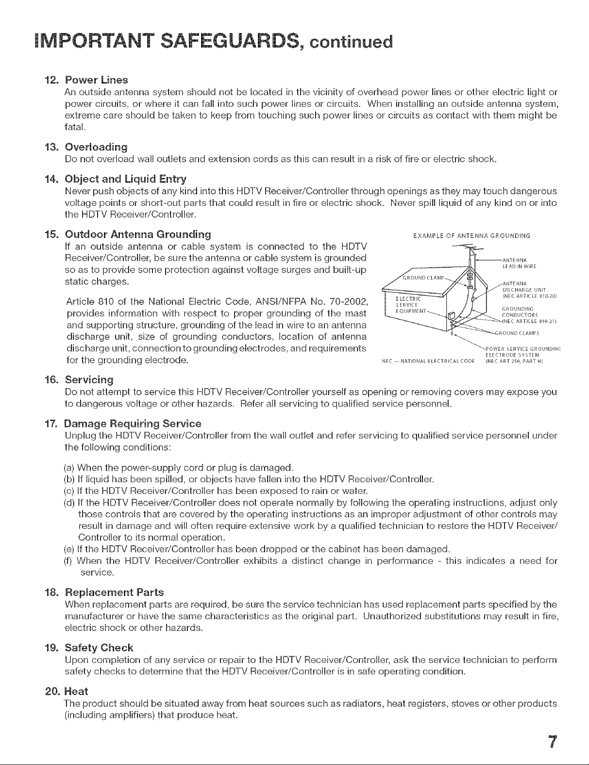
15.
Outdoor Antenna Grounding
EXAMPLE OF ANTENNA GROUNDING
if an outside antenna or cable system is connected to the HDTV
Receiver/Controller, be sure the antenna or cable system is grounded
so as to provide some protection against voltage surges and built-up
static charges.
Article 810 of the National Electric Code, ANS[/NFPA No. 70-2002,
provides information with respect to proper grounding of the mast
and supporting structure, grounding of the lead in wire to an antenna
GROUND CLAMP
LEAD iN WiRE
ANTENNA
DISCHARGE UNIT
(NEC ARTICLE slo 20)
GROUNDING
CONDUCTORS
(NEC ARTICLE 810 21)
discharge unit, size of grounding conductors, location of antenna
discharge unit, connection to grounding electrodes, and requirements
for the grounding electrode.
16.
Servicing
NEC NATIONAL E LECTRICAL CODE (NEC AR] 250, PART N)
_POWER SERVICE GROUNDING
ELECTRODE SYSTEM
Do not attempt to service this HDTV Receiver/Controller yourself as opening or removing covers may expose you
to dangerous voltage or other hazards. Refer all servicing to qualified service personnel.
17.
Damage Requiring Service
Unplug the HDTV Receiver/Controller from the wall outlet and refer servicing to qualified service personnel under
the following conditions:
(a) When the power-supply cord or plug is damaged.
(b) if liquid has been spilled, or objects have fallen into the HDTV Receiver/Controller.
(c) if the HDTV Receiver/Controller has been exposed to rain or water.
(d) if the HDTV Receiver/Controller does not operate normally by following the operating instructions, adjust only
those controls that are covered by the operating instructions as an improper adjustment of other controls may
result in damage and will often require extensive work by a qualified technician to restore the HDTV Receiver,,"
Controller to its normal operation.
(e) If the HDTV Receiver/Controller has been dropped or the cabinet has been damaged.
(f) When the HDTV Receiver/Controller exhibits a distinct change in performance - this indicates a need for
service.
18.
Replacement Parts
When replacement parts are required, be sure the service technician has used replacement parts specified by the
manufacturer or have the same characteristics as the original part. Unauthorized substitutions may result in fire,
electric shock or other hazards.
19.
Safety Check
Upon completion of any service or repair to the HDTV Receiver/Controlbr, ask the service technician to perform
safety checks to determine that the HDTV Receiver/Controlbr is in safe operating condition.
20.
Heat
The product should be situated away from heat sources such as radiators, heat registers, stoves or other products
(including amplifiers) that produce heat.
7
Thanks...
We are honored that you chose Mitsubishi as your path to upgrading your high
definition monitor dLsplay to a furl HDTV. The HD-6000 Lsdesigned to become
the cornerstone of your home entertainment system, offering the flexibility of
using both digital sources and analog sources in an advanced, but simple to use
single control system. It provides advanced user interface connections such as
CableCARD TM, IEEE 1394 and HDML You have the ability to record to an internal
120GB TV DLsc Internal Digital Video Recorder (DVR). The HD-6000 Lsready to
provide for your enjoyment for the next several years.
Whether thLsis part of a Mitsubishi LT-4260 HDTV package, an upgrade to your
MitsubLshi HD-upgradeable TV or dLsplay monitor or the HD-6000 Lsused to
upgrade dLsp/ays from other manufacturers, we hope this will bring you many
hours of enjoymenL
Mitsubishi DigitaJ EJectronics America, inc.
8
HDo6000 Receiver/Controm_er Overview
Accessories ................................................................................ 10
SpeciaU Features ........................................................................ 11
Front Control Panel .................................................................... 12
Back Panel .................................................................................. 13
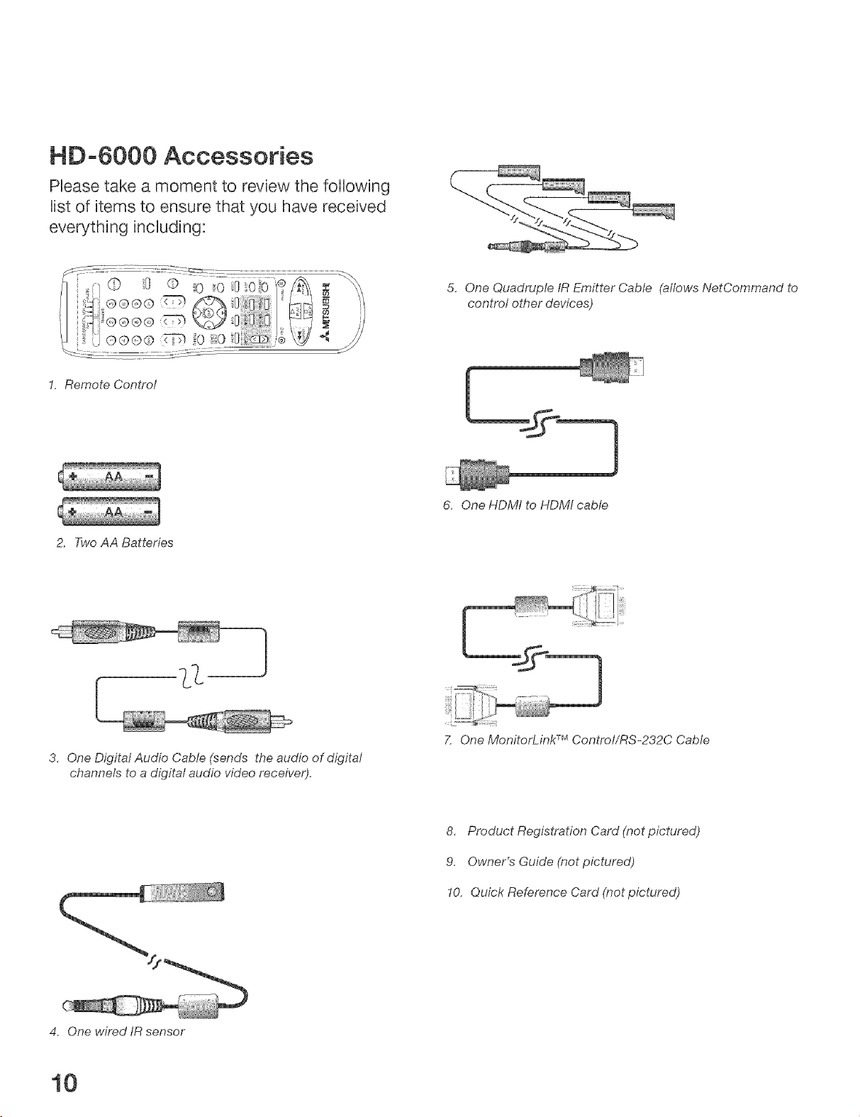
HD=6000 Accessories
PUease take a moment to review the following
Uistof items to ensure that you have received
everything incUuding:
1. Remote Control
2. Two AA Batteries
5, One Quadruple IR Emitter Cable (allows NetCommand to
control other devices)
6. One HDMf to HDMI cable
3, One Digital Audio Cable (sends the audio of digitaf
channels to a digital audio video receiver).
4. One wired IR sensor
10
7. One MonitorLink TMControt/RS-232C Cable
8, Product Registration Card (not pictured)
9. Owner's Guide (not pictured)
!0. Quick Reference Card (not pictured)
SpeciaJ Features
Your new HD-6000 High Definition teJevision receiver/controJJer has many speciaJ features
that turn your high definition dispJay monitor into a fuJJy integrated HDTV. This makes it
the perfect controJ center for your high definition dispJay monitor and home entertainment
system. These speciaJ features include:
MuJtipJe Connection CapabiJity
On the compact HD-6000 back panei you will find a full compbment of the connections
needed for the most sophisticated home theater system, hcluded are standard Audio/Video/
S-Video, wideband component video, FireWire®, EEE 1394, CabbCARD and both an HDMI
Input and an HDMI Output.
TV Disc JnternaJ DigitaJ Video Recorder (DVR)
TV Disc is an internal 120GB high definition hard disk drive recorder (also called a digital video
recorder or DVR). This exciting feature may record as much as 12 hours of high definition TV
programming and includes live TV pause with instant replay. Please note that some of the disk
drive space is used by TV Pause, so not all 120GB is available for recording.
It is able to record digital and analog programs received from CabbCARD TMchannels, Antenna
1, Antenna 2, devices connected to Input 1, 2 or IEEE 1394 devices. Now you can record
a high definition program and watch it later without any picture quality loss and without a
VCR. Recordings on the TV Disc can be sent by IEEE 1394 to D-VHS VCRs or to other JEEE
1394 compatible TVs. When recording analog programs, TV Disc will even use Dolby Digital
Record to convert the analog stereo to high quality digital stereo compatible with Dolby Digital
decoding surround receivers.
DigitaJ CabJe Ready (CabJeOARD TM)
Your widescreen Mitsubishi HDTV receiver/controlbr is "Plug-and-Play" ready. It can
descrambb a cable provider's one-way digital signals with the use of a CabbCARD security
module+ The CabbCARD is used in place of a traditional cable box to access digital cable
programming (including high definition). Contact your local cable provider for availability
information and service details.
NetOommand ® Home Network ControJ System
Your Mitsubishi HDTV receiver/controlbr offers a new level of networking to combine selected
older products with new and future digital products. NetCommand supports JEEE1394
connections, Audio Video Control system (AViC), 5C copy protection and JRcontrol of selected
older products such as VCRs, DVD players, cable boxes or satellite receivers. NetCommand
includes the ability to learn remote control signals directly from the remote control of many
devices, allowing you to customize the NetCommand system in a way that works best for your
viewing+
LT-4260 CompatibiJity
The HD-6000 is designed to work with all of the features of the Mitsubishi LT-4260 LCD HDTV
display. The HD-6000 has the correction connection to work with the authorized card reader
that is in the LT-4260.
11
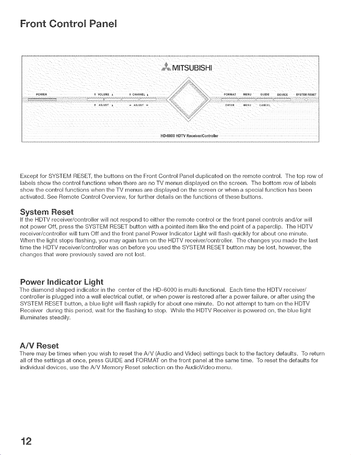
Front ControJ PaneJ
MITSUBJSHJ
HD-6000 HDTV Receive_lControimer
Except for SYSTEM RESET, the buttons on the Front Control Panel duplicated on the remote control. The top row of
labels show the control functions when there are no TV menus displayed on the screen. The bottom row of labels
show the control functions when the TV menus are displayed on the screen or when a special function has been
activated. See Remote Control Overview, for further details on the functions of these buttons.
System Reset
If the HDTV receiver/controller wiii not respond to either the remote control or the front panel controls and/or wiii
not power Off, press the SYSTEM RESET button with a pointed item like the end point of a paperclip. The HDTV
receiver/controller wiii turn Off and the front panel Power Indicator Light wiii flash quickly for about one minute.
When the light stops flashing, you may again turn on the HDTV receiver/controller. The changes you made the last
time the HDTV receiver/controller was on before you used the SYSTEM RESET button may be lost, however, the
changes that were previously saved are not IosL
Power indicator Light
The diamond shaped indicator in the center of the HD-6000 is multi-functional. Each time the HDTV receiver,,"
controller is plugged into a wall electrical outlet, or when power is restored after a power failure, or after using the
SYSTEM RESET button, a blue light wiii flash rapidly for about one minute. Do not attempt to turn on the HDTV
Receiver during this period, wait for the flashing to stop. While the HDTV Receiver is powered on, the blue light
illuminates steadily.
A/V Reset
There may be times when you wish to reset the AiV (Audio and Video) settings back to the factory defaults. To return
all of the settings at once, press GUIDE and FORMAT on the front panel at the same time. To reset the defaults for
individual devices, use the AiV Memory Reset selection on the AudioVideo menu.
12
Back Panel
1. 2. 3. 4. 5. 6. 7. 8.
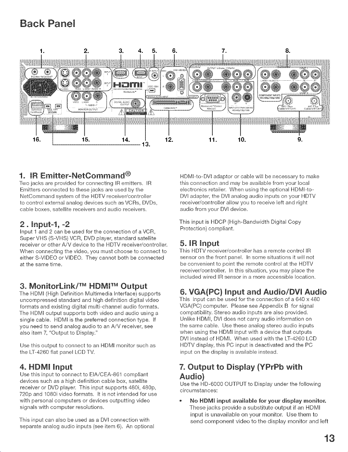
1. IR Emitter°NetCommand ®
Two jacks are provided for connecting IR emitters. JR
Emitters connected to these jacks are used by the
NetCommand system of the HDTV receiver/controller
to control external analog devices such as VCRs, DVDs,
cable boxes, sateiJite receivers and audio receivers.
2. Input-l, -2
Input 1 and 2 can be used for the connection of a VCR,
Super VHS (S-VHS) VCR, DVD player, standard satellite
receiver or other A/V device to the HDTV receiver/controller.
When connecting the video, you must choose to connect to
either S=VIDEO or VIDEO. They cannot both be connected
at the same time.
3. MonitorLink/TM HDMP MOutput
The HDMI (High Definition Multimedia Interface) supports
uncompressed standard and high definition digital video
formats and existing digitaJ multi-channel audio formats.
The HDMI output supports both video and audio using a
single cabJe. HDMI is the preferred connection type. If
you need to send analog audio to an A/V receiver, see
aJso item 7, "Output to Display."
Use this output to connect to an HDMI monitor such as
the LT=4260 fiat panel LCD TV.
HDMI=to-DVI adaptor or cabJe wilI be necessary to make
this connection and may be available from your IocaJ
eJectronics retailer. When using the optional HDMI-to-
DVl adapter, the DVI analog audio inputs on your HDTV
receiver/controiler allow you to receive left and right
audio from your DVI device.
This input is HDCP (High-Bandwidth DigitaI Copy
Protection) compliant.
5. IR Input
This HDTV receiver/controiler has a remote control IR
sensor on the front panel. In some situations it wilI not
be convenient to point the remote controJ at the HDTV
receiver/controilen In this situation, you may place the
included wired IR sensor in a more accessible Jocation.
6. VGA(PC) Input and Audio/DVl Audio
This input can be used for the connection of a 640 x 480
VGA(PC) computer. PJease see Appendix B for signal
compatibility. Stereo audio inputs are atso provided.
Unlike HDMI, DVl does not carry audio information on
the same cable. Use these analog stereo audio inputs
when using the HDMI input with a device that outputs
DVl instead of HDMI. When used with the LT-4260 LCD
HDTV display, this PC input is deactivated and the PC
input on the display is avaiJabJe instead.
4. HDMI Input
Use this input to connect to EIA/CEA-861 compliant
devices such as a high definition cable box, sateilite
receiver or DVD piayer. This input supports 480i, 480p,
720p and 1080i video formats. It is not intended for use
with personal computers or devices outputting video
signals with computer resoJutions.
This input can also be used as a DVl connection with
separate analog audio inputs (see item 6). An optional
7, Output to DispJay (YPrPb with
Use the HD-6000 OUTPUT to Display under the following
circumstances:
No HDMJ input available for your display monitor°
These jacks provide a substitute output if an HDMI
input is unavailable on your monitor. Use them to
send component video to the display monitor and left
13
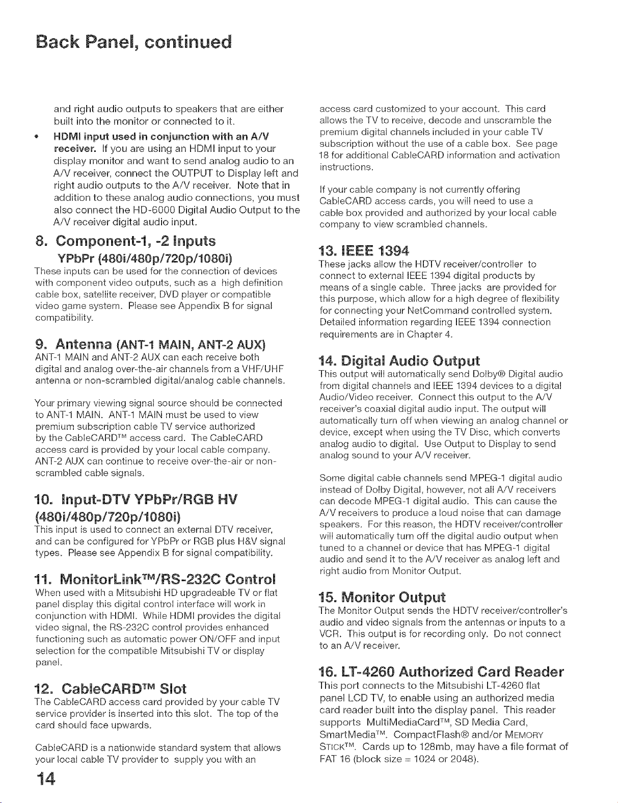
Back PaneJ, continued
and right audio outputs to speakers that are either
buiHt into the monitor or connected to it.
HDMi input used in conjunction with an A/V
receiver. If you are using an HDMI input to your
dispHay monitor and want to send anaHog audio to an
AiV receiver, connect the OUTPUT to DispHay Heft and
right audio outputs to the AiV receiver. Note that in
addition to these anaHog audio connections, you must
aHso connect the HD-6000 DigitaH Audio Output to the
AiV receiver digitaH audio input.
8. Componentol, o2 inputs
YPbPr (480i/480p/720p/1080i)
These inputs can be used for the connection of devices
with component video outputs, such as a high definition
cable box, satellite receiver, DVD player or compatible
video game system. Please see Appendix B for signal
compatibility.
9. Antenna (ANT-I MAIN, ANT-2 AUX)
ANT-1 MAIN and ANT-2 AUX can each receive both
digital and analog over-the-air channels from a VHF/UHF
antenna or non-scrambled digital/analog cable channels.
Your primary viewing signat source should be connected
to ANT-1 MAIN. ANT-1 MAIN must be used to view
premium subscription cable TV service authorized
by the CabIeCARD TM access card. The CabIeCARD
access card is provided by your local cable company.
ANT-2 AUX can continue to receive over-the-air or non-
scrambled cable signals.
10, Jnput-DTV YPbPr/RGB HV
(480ii480p/720pi1080i)
This input is used to connect an external DTV receiver,
and can be configured for YPbPr or RGB plus H&V signal
types. Please see Appendix B for signal compatibility.
11. MonitorLinkTM/RSo2320 ControJ
When used with a Mitsubishi HD upgradeabIe TV or fiat
panel display this digital control interface wilI work in
conjunction with HDMJ. While HDMI provides the digital
video signal, the RS-232C control provides enhanced
functioning such as automatic power ON/OFF and input
selection for the compatible Mitsubishi TV or display
panel.
12. CabJeCARD TM SJot
The CableCARD access card provided by your cable TV
service provider is inserted into this slot. The top of the
card should face upwards.
CableCARD is a nationwide standard system that allows
your local cable TV provider to supply you with an
access card customized to your account. This card
allows the TV to receive, decode and unscramble the
premium digital channels included in your cable TV
subscription without the use of a cable box. See page
18 for additiona! CabJeCARD information and activation
instructions.
If your cable company is not currently offering
CabIeCARD access cards, you will need to use a
cable box provided and authorized by your local cable
company to view scrambled channels.
13. JEEE 1394
These jacks allow the HDTV receiver/controller to
connect to external JEEE 1394 digital products by
means of a single cable. Three jacks are provided for
this purpose, which allow for a high degree of flexibility
for connecting your NetCommand controlled system.
Detailed information regarding EEE 1394 connection
requirements are in Chapter 4.
14. DigitaJ Audio Output
This output will automatically send Dolby® Digital audio
from digital channels and iEEE 1394 devices to a digital
Audio/Video receiver. Connect this output to the A/V
receiver's coaxial digital audio input. The output will
automatically turn off when viewing an analog channel or
device, except when using the TV Disc, which converts
analog audio to digital. Use Output to Display to send
analog sound to your A/V receiver.
Some digital cable channels send MPEG-1 digital audio
instead of DoJby Digital, however, not all A/V receivers
can decode MPEG-1 digital audio. This can cause the
A/V receivers to produce a loud noise that can damage
speakers. For this reason, the HDTV receivericontrolIer
will automatically turn off the digital audio output when
tuned to a channel or device that has MPEG-1 digital
audio and send it to the A/V receiver as analog left and
right audio from Monitor Output.
15. Monitor Output
The Monitor Output sends the HDTV receiver/controller's
audio and video signals from the antennas or inputs to a
VCR. This output is for recording only. Do not connect
to an A/V receiver.
16, LT-4260 Authorized Card Reader
This port connects to the Mitsubishi LT-4260 flat
panel LCD TV, to enable using an authorized media
card reader built into the display panel. This reader
supports MultiMediaCard TM, SD Media Card,
SmartMedia TM. CompactFlash® and/or MEMORY
STICKTM. Cards up to 128mb, may have a file format of
FAT 16 (block size = 1024 or 2048).
14
Connecting
E×ternaU Devices & NetCommand® Setup .................................. 16
WaN Outlet CabUe ........................................................................... 17
Cable Box ........................................................................................ 17
CableCARD TMTechnoUogy ............................................................. 18
Single Lead Antenna ...................................................................... lg
Separate UHF and VHF Antennas ............................................... 19
Antenna or WaUl OutUet CabUe to a VCR (Audio & Video} ............ 20
CabUe Box to a VCR (Audio & Video} ............................................ 2i
A/V Receiver or Stereo System .................................................... 22
Satellite Receiver or Other Device with S-Video ........................ 22
MonitorLink TMControl ................................................................... 23
Computer with a PC Monitor Output ........................................... 23
DTV Receiver
with Component Video ............................................................... 24
with RGB, HV Video ................................................................... 25
DVD PUayer with Component Video .............................................. 26
DispJay Monitor with Component Video ...................................... 26
DispJay Monitor with an NDMJ input ............................................ 27
HDMJ Source Device ...................................................................... 27
DVJ Device ....................................................................................... 28
To the Mitsubishi LTo4260 LCD TV ............................................... 29
JR Emitter NetCommand® ............................................................ 30
JR Sensor input .............................................................................. 31
CompatibJe JEEE 1394 Devices ..................................................... 32
HeJpfuJ Hints ................................................................................... 34
important Notes ............................................................................. 35
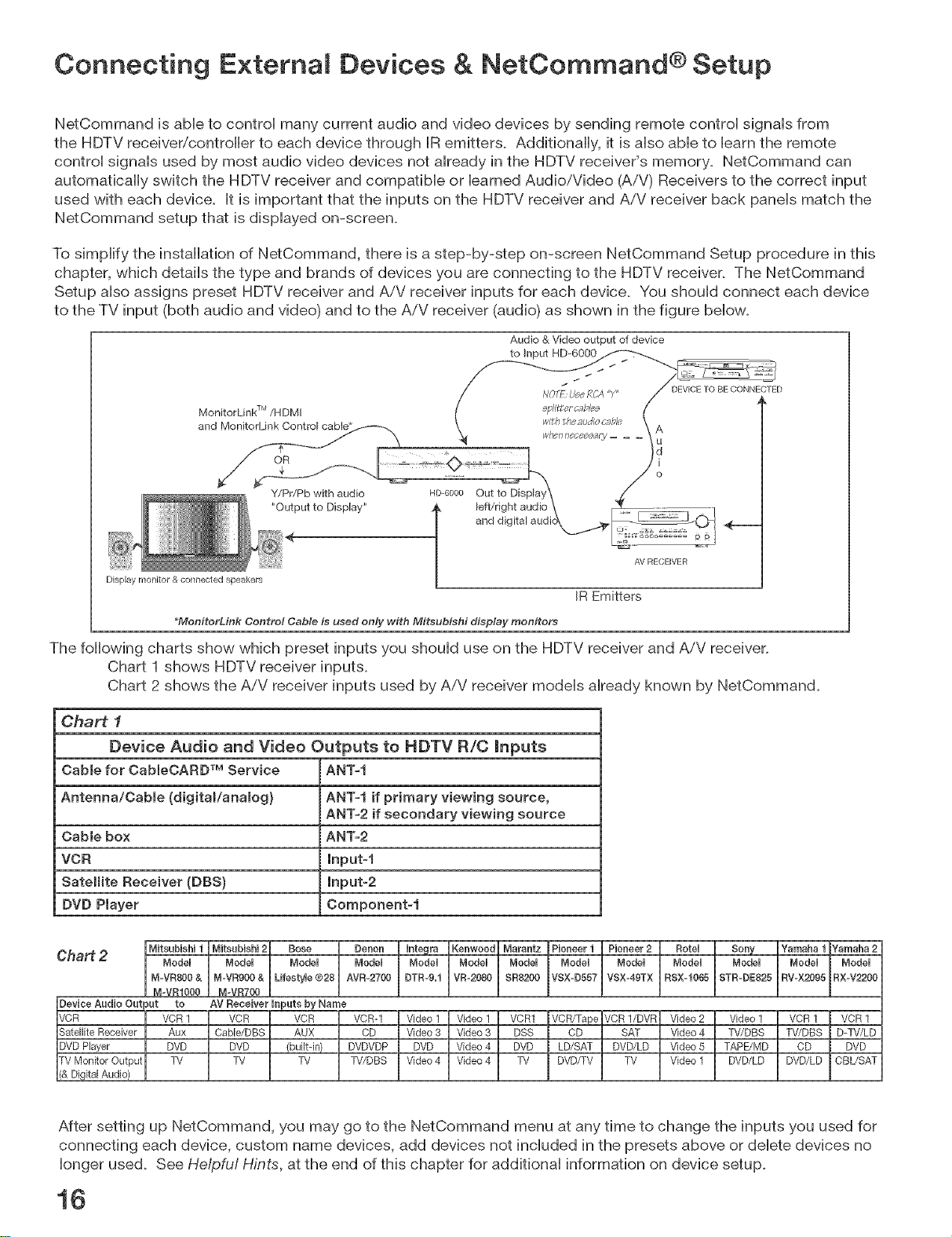
Connecting E×temai Devices & NetCommand ® Setup
NetCommand is able to control many current audio and video devices by sending remote control signals from
the HDTV receiver/controller to each device through IR emitters, Additionally, it is also able to barn the remote
control signals used by most audio video devices not already in the HDTV receiver's memory, NetCommand can
automatically switch the HDTV receiver and compatible or learned Audio/Video (A/V) Receivers to the correct input
used with each device, It is important that the inputs on the HDTV receiver and AiV receiver back panels match the
NetOommand setup that is displayed on-screen,
To simplify the installation of NetCommand, there is a step-by-step on-screen NetCommand Setup procedure in this
chapter, which details the type and brands of devices you are connecting to the HDTV receiver, The NetCommand
Setup also assigns preset HDTV receiver and AiV receiver inputs for each device, You should connect each device
to the TV input (both audio and video) and to the AiV receiver (audio) as shown in the figure below,
Audio & Video output of device
AV RECEIVER
Display monitor & connected speakers
IR Emitters
_MonitorLink Control Cable is used only with Miteubishi display monitors
The following charts show which preset inputs you should use on the HDTV receiver and AiV receiver,
Chart 1 shows HDTV receiver inputs,
Chart 2 shows the AiV receiver inputs used by AiV receiver models already known by NetCommand,
Chart i
Device Audio and Video Outputs to HDTV R/C mnputs
Cable for CableOARDTM Service ANT-I
Antenna/Oabme (digital/anamog} ANT-I if primary viewing source,
ANT-2 if secondary viewing source
Cabmebox ANT-2
VCR lnput-f
Satellite Receiver (DBS) Input-2
DVD Player Component-i
Chart 2
Bose I DenenI I.tegraIKenweedIMarantzlPieneeriI pieneer21 ReteuI sew IYamahai_
After setting up NetCommand, you may go to the NetCommand menu at any time to change the inputs you used for
connecting each device, custom name devices, add devices not included in the presets above or delete devices no
longer used. See Helpfu! Hints, at the end of this chapter for additional information on device setup.
16
Connecting a Wall Out et Cable or Cable Box
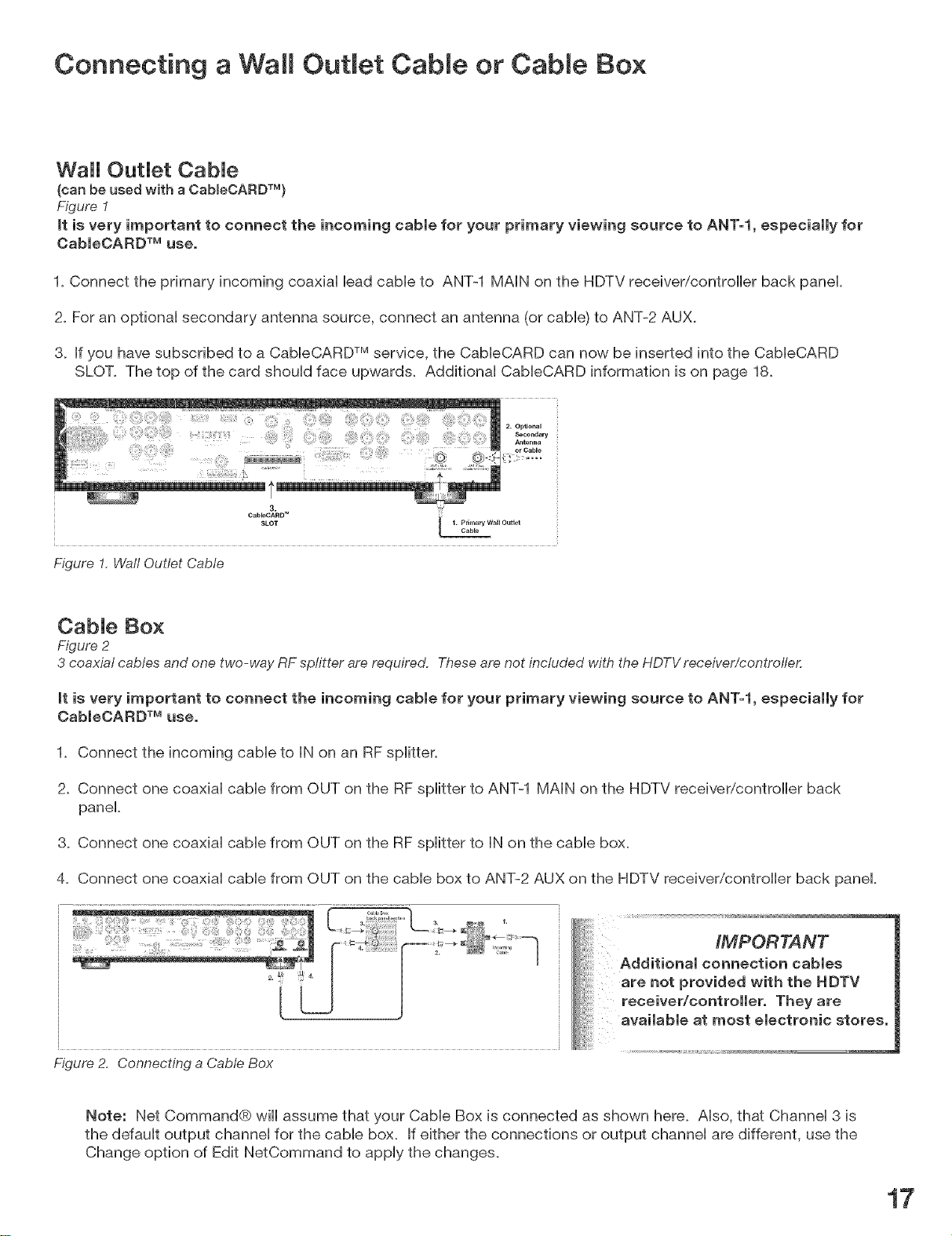
Wall OutJet CabJe
(can be used with a CabmeCARDTM)
Figure 1
It is very important to connect the incoming cable for your primary viewing source to ANT=l, especially for
CaBIeCARD TM use.
1. Connect the primary incoming coaxiaH HeadcabHeto ANT-1 MAiN on the HDTV receiver/controller back panel
2. For an optionaH secondary antenna source, connect an antenna (or cabHe)to ANT-2 AUX.
3. Ifyou have subscribed to a CaMeCARD TMservice, the CaMeCARD can now be inserted into the CaMeCARD
SLOT. The top of the card shouHd face upwards. Additional CableCARD information is on page 18.
3.
CableCARD"
SLOT L 1" CablePri_r_arYWallOlltlet
Figure 1, Wall Outlet Cable
Cable Box
Figure 2
3 coaxial cables and one two-way RFsplitter are required. Theseare not included with the HDTVreceiver/controfle,c
it is very important to connect the incoming cable for your primary viewing source to ANT=l, especially for
CableOARD TM use.
1. Connect the incoming cable to IN on an RF splitter.
2. Connect one coaxial cable from OUT on the RF splitter to ANT-1 MAIN on the HDTV receiver/controller back
panel.
3. Connect one coaxial cable from OUT on the RF splitter to IN on the cable box.
4. Connect one coaxial cable from OUT on the cable box to ANT-2 AUX on the HDTV receiver/controller back panel.
IMPORTANT
Additional connection cables
are not provided with the NDTV
receiver/controller. They are
available at most electronic stores.
Figure 2. Connecting a Cable Box
Note: Net Command® will assume that your Cable Box is connected as shown here. Also, that Channel 3 is
the default output channel for the cable box. If either the connections or output channel are different, use the
Change option of Edit NetCommand to apply the changes.
17
Cab eCARD TM Technology
CabJeCARD TechnoJogy
CabbCARD is a nationwide system standard that
allows your local cabb TV provider to supply you with
an access card customized to your account. This
card allows your HDTV receivericontroibr to receive,
decode and unscrambb the premium digital channels
included in your cabb TV subscription, without the use
of a cabb box. It also allows your cabb provider to
automatically update and change your subscription.
When you move to a new cabb provider's area, you
simply return the CabbCARD to the original cable
provider and get a new card from your new cable
provider.
Please note that CabbCARD is a new technology and
your local cable provider may not currently be offering
this service. As time passes, this system will become
broadly supported by most cable providers.
The CabbCARD system is "unidirectional" which
means your cable provider can send updates to the
access card and HDTV receivericontrolbr, however,
the HDTV receiver/controlbr cannot send back signals
such as requests for Video-On-Demand or Pay-per-
View by remote control.
Digital cable channels authorized by the CabbCARD
will be available on the Firewire® IEEE 1394 network
and can be shared by other products on the network.
Some digital channels or programs may not be copied
or recorded because of copy restriction limits set by
the content owners or copyright holders.
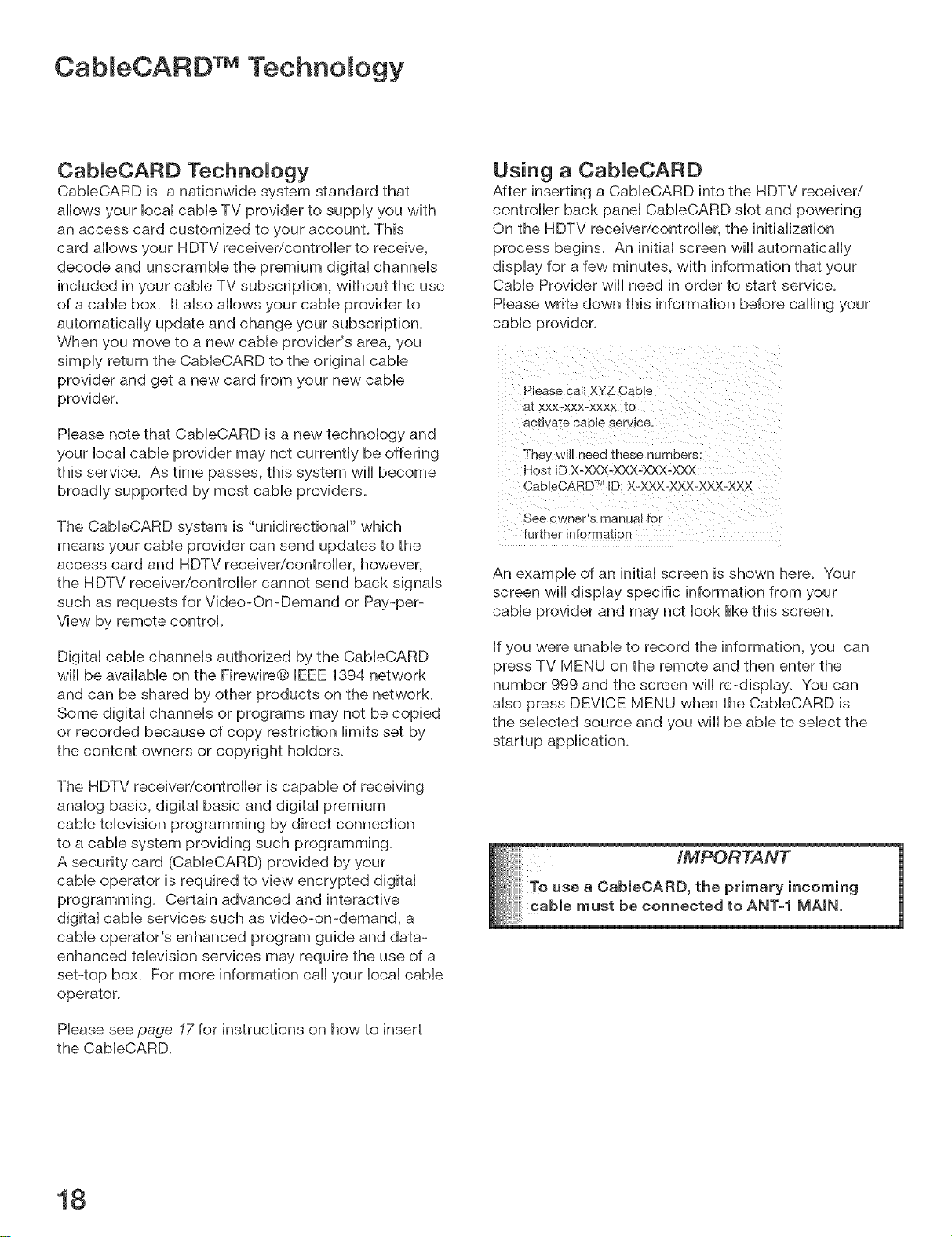
Using a CabJeCARD
After inserting a CableCARD into the HDTV receiver/
controller back panel CableCARD slot and powering
On the HDTV receiver/controller, the initialization
process begins. An initial screen will automatically
display for a few minutes, with information that your
Cable Provider will need in order to start service.
Please write down this information before calling your
cable provider.
Please call XYZ Cable
at xxx-xxx-xxxx to
acttva-[e cable service.
They will need these numbers:
Host ID X-XXX-XXX-XXX-XXX
CableCARD TMID: X-XXX-XXX-XXX-XXX
See on nets manual for
further" information
An example of an initial screen is shown here. Your
screen wiii display specific information from your
cable provider and may not look like this screen.
If you were unable to record the information, you can
press TV MENU on the remote and then enter the
number 999 and the screen will re-display. You can
also press DEVICE MENU when the CableCARD is
the selected source and you will be able to select the
startup application.
The HDTV receiver/controlbr is capable of receiving
analog basic, digital basic and digital premium
cable television programming by direct connection
to a cable system providing such programming.
A security card (CabbCARD) provided by your
cable operator is required to view encrypted digital
programming. Certain advanced and interactive
digital cable services such as video-on-demand, a
cable operator's enhanced program guide and data-
enhanced television services may require the use of a
set-top box. For more information call your local cable
operator.
Please see page 17 for instructions on how to insert
the CableCARD.
18
iMPORTANT
e a CableOARD, the primary incoming

Connecting a Lead Antenna or Separate UHF and VHF
Antenna
Lead Antenna motfor use with CabJeCARD TM}
Figure 3
For antennas with twin flat lead
A 300-Ohm to 75-Ohm transformer is required, This is not included with the HDTVreceiver/controlle_ but is available at most
electronics stores,
1. For antenna with twin fiat leads, connect the 300-Ohm twin leads to the 300-Ohm to 75-Ohm transformer.
2. Push the 75-Ohm side of the transformer onto ANT-1 MAiN on the HDTV receiver/controller back panel.
For cable or antenna with coaxial lead
3. Connect the coaxial lead directly to ANT-1 MAiN on the HDTV receiver/controller back panel.
Mitsubishi strongly recommends against
using antennas with twin flat leads, Twin
flat lead antenna wires are subject to
interference which may adversely affect
the performance of the TV, We recommend
using coaxial antenna cable.
\
Figure 3. Connecting a Single Antenna
Separate UHF and VHF Antenna
Figure 4
A UHF/VHF combiner is required, This is not included with the HDTVreceiver/controlle,c
1. Connect the UHF and VHF antenna leads to the UHF/VHF combiner.
2. Push the combiner onto ANT-1 MAIN on the HDTV receiver/controller back panel.
Figure 4. Connecting separate UHF and VHF Antennas
VHF _/t ennc_
[Chc_nneP 2 13)
19
Connecting an Antenna or Wai Out et Cable to a VCF{ (Audio &
Video)
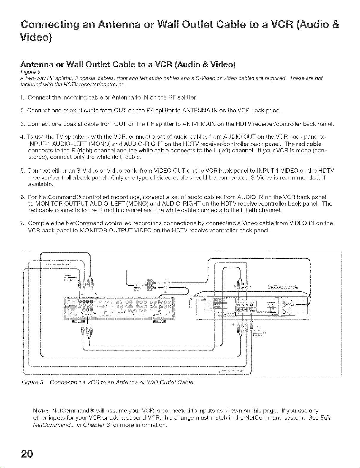
Antenna or Wal OutJet CabJe to a VCR (Audio & Video)
Figure 5
A two-way RF splitter, 3 coaxial cables, right and left audio cables and a S-Video or Video cables are required, Thesearenot
included with the HDTVreceiver/controller,
1. Connect the incoming cabb or Antenna to IN on the RF spltter.
2. Connect one coaxial cabb from OUT on the RF spltter to ANTENNA IN on the VCR back panel.
3. Connect one coaxial cabb from OUT on the RF spltter to ANT-1 MAIN on the HDTV receiver/controler back panel.
4. To use the TV speakers with the VCR, connect a set of audio cabbs from AUDIO OUT on the VCR back panel to
INPUT-1 AUDIO-LEFT (MONO) and AUDIO-RIGHT on the HDTV receivericontroler back panel. The red cable
connects to the R (right) channel and the white cable connects to the L (left) channel. If your VCR is mono (non-
stereo), connect only the white (left) cabb.
5. Connect either an S-Video or Video cable from VIDEO OUT on the VCR back panel to INPUT-1 VIDEO on the HDTV
receiver/controlerback panel Only one type of video cable should be connected. S-Video is recommended, if
avalable.
6. For NetCommand® controlled recordings, connect a set of audio cables from AUDIO IN on the VCR back panel
to MONITOR OUTPUT AUDIO-LEFT (MONO) and AUDIO-RIGHT on the HDTV receivericontroler back panel. The
red cable connects to the R (right) channel and the white cable connects to the L (left) channel.
7. Complete the NetCommand controlled recordings connections by connecting a Video cable from VIDEO IN on the
VCR back panel to MONITOR OUTPUT VIDEO on the HDTV receiver/controler back panel.
Figure 5. Connecting a VCR to an Antenna or Waft Outlet Cab/e
Note: NetCommand® will assume your VCR is connected to inputs as shown on this page. If you use any
other inputs for your VCR or add a second VCR, this change must match in the NetCommand system. See Edit
NetCommand... in Chapter 3 for more information.
2O
Connecting a Cable Box to a VCR (Audio & Video)
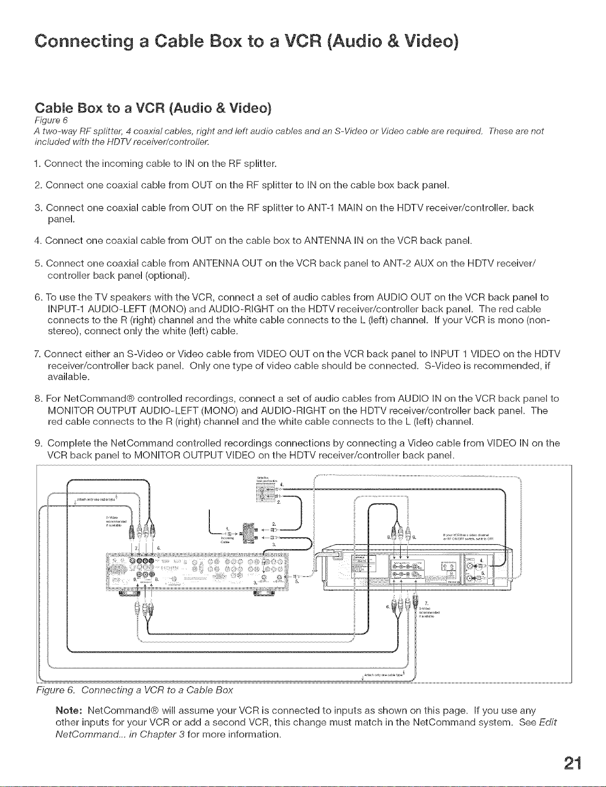
Cable Box to a VCR (Audio & Video)
Figure 6
A two-way RF splitter, 4 coaxial cables, right and Ieft audio cables and an S-Video or Video cable are required. Theseare not
included with the HDTVrece/ver/controller.
1. Connect the incoming cable to IN on the RF splitter.
2. Connect one coaxial cable from OUT on the RF splitter to IN on the cable box back panel.
3. Connect one coaxial cable from OUT on the RF splitter to ANT-1 MAIN on the HDTV receiver/controller, back
panel
4. Connect one coaxial cable from OUT on the cable box to ANTENNA IN on the VCR back panel
5. Connect one coaxial cable from ANTENNA OUT on the VCR back panel to ANT-2 AUX on the HDTV receiver/
controller back panel (optional).
6. To use the TV speakers with the VCR, connect a set of audio cables from AUDIO OUT on the VCR back panel to
INPUT-1 AUDIO-LEFT (MONO) and AUDIO-RIGHT on the HDTV receiver/controller back panel. The red cable
connects to the R (right) channel and the white cable connects to the L (left) channel. If your VCR is mono (non-
stereo), connect only the white (left) cable.
7. Connect either an S-Video or Video cable from VIDEO OUT on the VCR back panel to INPUT 1 VIDEO on the HDTV
receiver/controller back panel. Only one type of video cable should be connected. S-Video is recommended, if
available.
8. For NetCommand@ controlled recordings, connect a set of audio cables from AUDIO IN on the VCR back panel to
MONITOR OUTPUT AUDIO-LEFT (MONO) and AUDIO-RIGHT on the HDTV receiver/controller back panel. The
red cable connects to the R (right) channel and the white cable connects to the L (left) channel.
9. Complete the NetCommand controlled recordings connections by connecting a Video cable from VIDEO IN on the
VCR back panel to MONITOR OUTPUT VIDEO on the HDTV receiver/controller back panel.
L I
orREON/OFF_itch _t itto OFF
L ....
{ ........
Figure 6. Connecting a VCR to a CaMe Box
Note: NetCommand® wiii assume your VCR is connected to inputs as shown on this page. If you use any
other inputs for your VCR or add a second VCR, this change must match in the NetCommand system. See Edit
NetCommand... in Chapter 3 for more information.
21
Connecting an A/V Receiver or Stereo System or
a Satellite Receiver or Other Device with S-Video
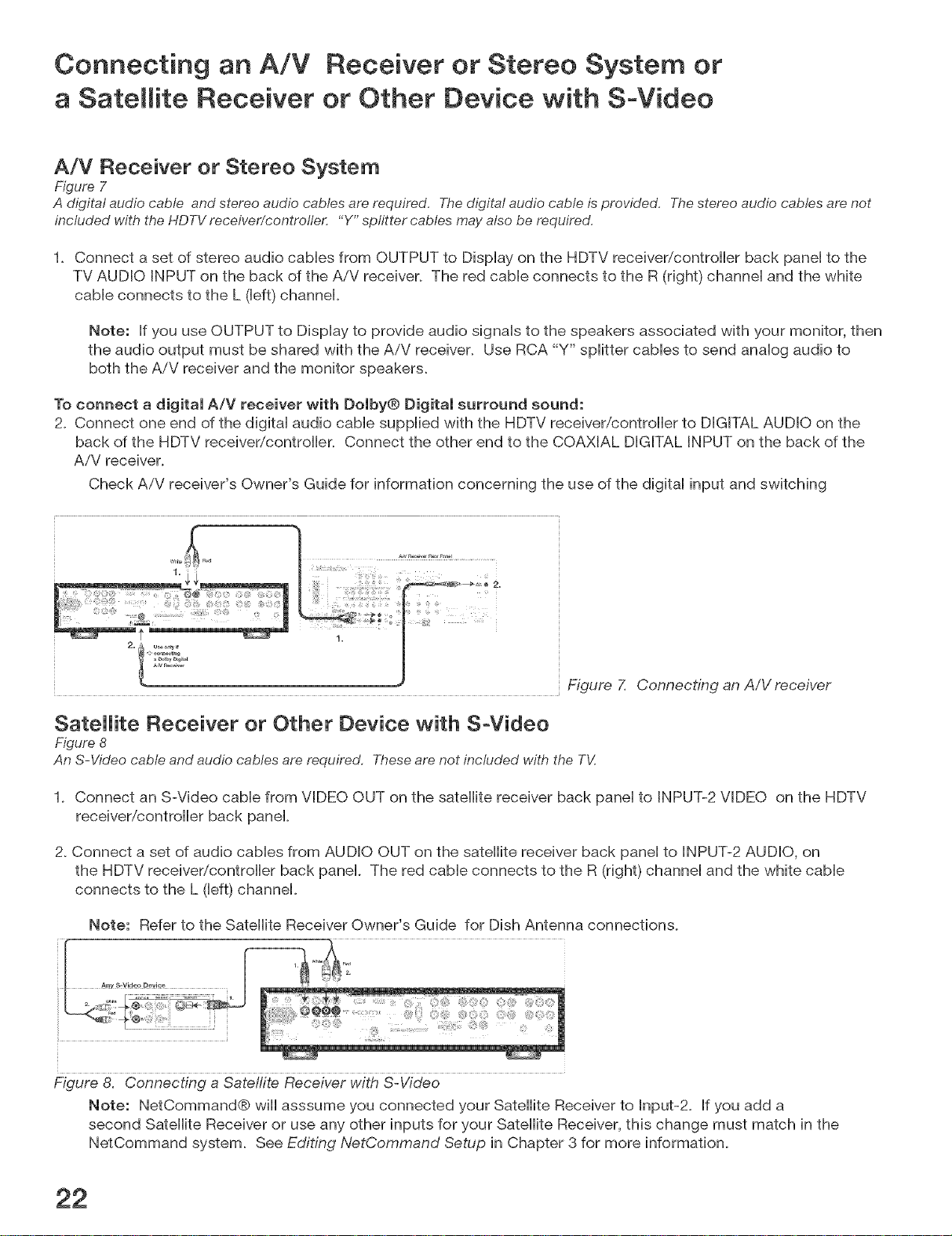
A/V Receiver or Stereo System
Figure 7
A digital audio cable and stereo audio cables arerequired. The digital audio cable isprovided. Thestereo audio cables are not
included with the HDTVreceiver/controller. "Y" splitter cables may also be required.
1_ Connect a set of stereo audio cables from OUTPUT to Display on the HDTV receiver/controller back panel to the
TV AUDIO INPUT on the back of the AiV receiver. The red cable connects to the R (right) channel and the white
cable connects to the L (left) channel.
Note: If you use OUTPUT to Display to provide audio signals to the speakers associated with your monitor, then
the audio output must be shared with the AiV receiver. Use RCA "Y" splitter cables to send analog audio to
both the AiV receiver and the monitor speakers.
To connect a digital A/V receiver with Dolby® Digital surround sound:
2_ Connect one end of the digital audio cable supplied with the HDTV receiver/controller to DIGITAL AUDIO on the
back of the HDTV receivericontroller. Connect the other end to the COAXIAL DIGITAL INPUT on the back of the
AiV receiver.
Check AiV receiver's Owner's Guide for information concerning the use of the digital input and switching
Figure Z Connecting an A/V receiver
Satellite Receiver or Other Device with S-Video
Figure 8
An S-Video cable and audio cables are required. These are not included with the TV.
1_ Connect an S-Video cable from VIDEO OUT on the satellite receiver back panel to INPUT-2 VIDEO on the HDTV
receiver/controller back panel
2_Connect a set of audio cables from AUDIO OUT on the satellite receiver back panel to INPUT-2 AUDIO, on
the HDTV receiver/controller back panel. The red cable connects to the R (right) channel and the white cable
connects to the L (left) channel.
Note: Refer to the Satellite Receiver Owner's Guide for Dish Antenna connections.
Figure 8. Connecting a Sate!rite Receiver with S-Video
Note: NetCommand® will asssume you connected your Satellite Receiver to Input-2. If you add a
second Satellite Receiver or use any other inputs for your Satellite Receiver, this change must match in the
NetCommand system. See Editing NetCommand Setup in Chapter 3 for more information.

Connecting MonitorLink TM Contro or
a Computer with a PC Monitor Output
MonitorLink ControJ (For Use onJy with Mitsubishi DispJay Monitor with
MonitorLink ControJ Connection}
Figure 9
A MonitorLink control cable is required and is provided,
This connection allows the HD-6000 to automatically turn on or off the compaflMe MitsubisM dispHay monitor, When
used wth the Mitsubishi 4260 LCD TV, the connections allow the HD-6000 to use the remote control sensor in front
of the TV, Connect the MonitorLink control cable from the MonitorLink control on the HD-6000 back panel to the
M-Link control on the TV back panel (MonitorLink is also called MonLink or M-Link, depending on the Mitsubishi
display monitor),
You will also want to connect the MonitorLink HDMI Output to the Mitsubishi monitor, as shown on page 27 or 28_
Section detail of
Mitsubishi
]_/back pallel
Figure 9. Connecting M-Link Control
Computer with a PC Monitor Output (Not for use when connected to the LT-4260 LCD TV)
Figure 10
A !5 pin PC monitor cable and an audio video cable is required, These are not included with the TV.
1_ Connect PC Monitor Out from the computer to PC Input on the HDTV receiver/controller back panel using a PC
compatible monitor cable, See Appendix B for PC signal compatibility,
2_Connect the L (left) and R (right) audio cables from the computer to PC AUDIO on the HDTV receiver/controller
back panel, If the computer's audio output is a single mini-jack, a splitter is needed to complete this connection,
Note: The HD-6000 PC input is only compatible with VGA resolution (640 x480, 60hz), If your display monitor
is capable of a higher resolution then you should connect the PC directly to the monitor,
Note: To utilize the benefits of a digital A/V receiver, connect your computer's digital audio out, if available, to a
digital input on your digital AiV receiver,
Figure 10. Connecting a Computer with a PC Monitor
23
DTV Connectors and Adaptors Connecting a DTV Receiver with
Component Video
DTV Connectors and Adaptors
Figure 1!
The HDTV receiver/controlbr back panel has 5 RCA-type connectors for the Input-DTV. The back panel of your
external DTV receiver may use RCA-type connectors or BNC-type connectors. If your DTV receiver comes with BNC
type connections, you will need to purchase BNC to RCA adaptors to connect the HDTV receivericontrolbr to the
DTV receiver. These adaptors should be available at most electronic supply stores.
IMPORTANT
See Appendix B for component video
signal compatibility information.
gital audio connections, see your
BNCto
RCA BNC Fitted to
Adaptor Connector Connection
Figure 11.
DTV Connectors and Adaptors
or
RCA
Connector
: DTV Receiver and A/V receiver Owner's
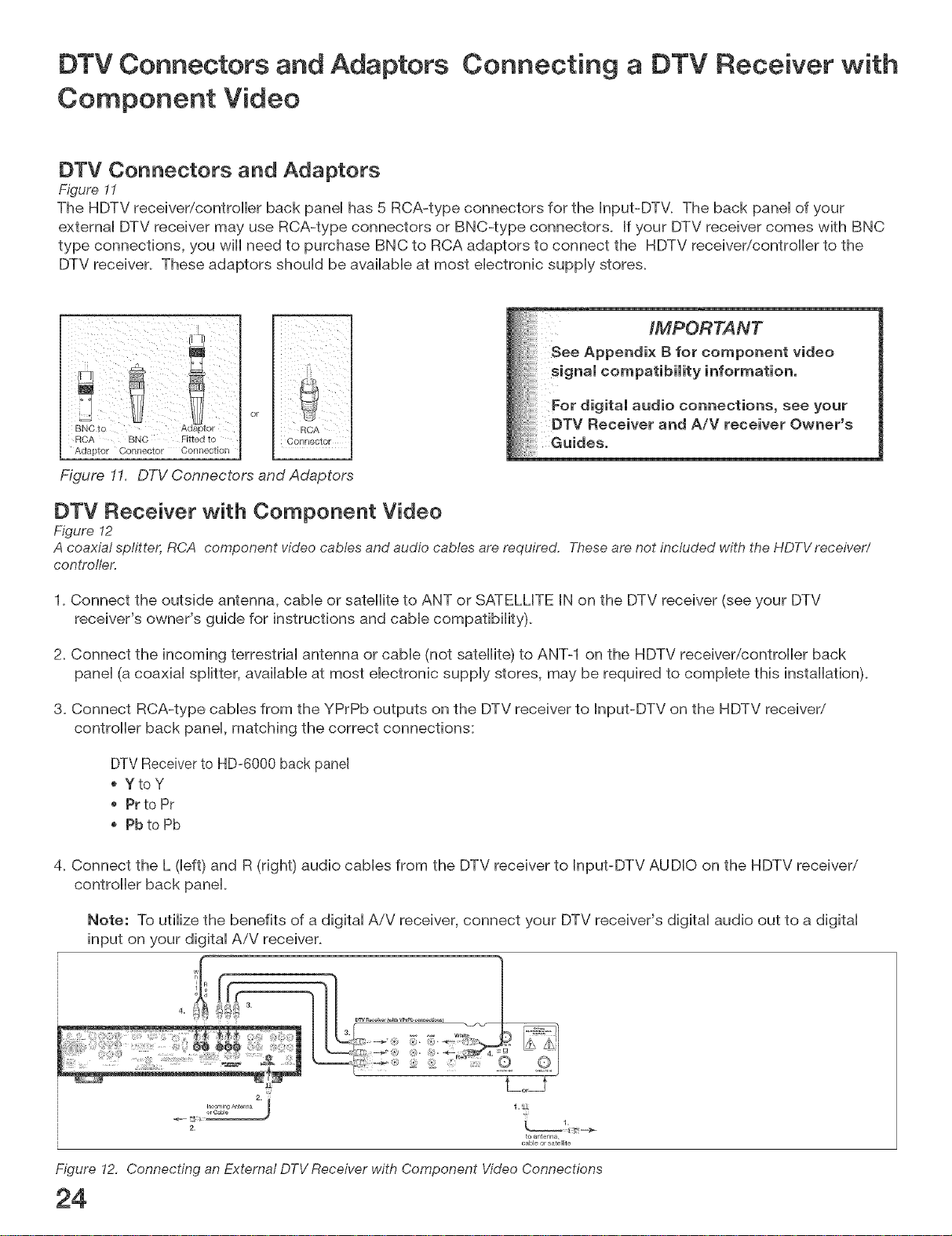
DTV Receiver with Component Video
Figure 12
A coaxial splitter, RCA component video cables and audio cables are required. Thesearenot included with the HDTVreceiver/
controller.
1. Connect the outside antenna, cable or satellite to ANT or SATELLITE IN on the DTV receiver (see your DTV
receiver's owner's guide for instructions and cable compatibility).
2. Connect the incoming terrestrial antenna or cable (not satellite) to ANT-1 on the HDTV receiver/controller back
panel (a coaxial splitter, available at most electronic supply stores, may be required to complete this installation).
3. Connect RCA-type cables from the YPrPb outputs on the DTV receiver to Input-DTV on the HDTV receiver/
controller back panel, matching the correct connections:
DTV Receiverto HD-6000 back panel
YtoY
Pr to Pr
Pb to Pb
4. Connect the L (left) and R (right) audio cables from the DTV receiver to Input-DTV AUDIO on the HDTV receiver/
controller back panel.
Note: To utilize the benefits of a digital AiV receiver, connect your DTV receiver's digital audio out to a digital
input on your digital AiV receiver.
• 3. _o ,_ White
to antenna,
cable or satellite
Figure !2, Connecting an External DTV Receiver with Component Video Connections
Connecting a DTV Receiver with RGB, HV Video
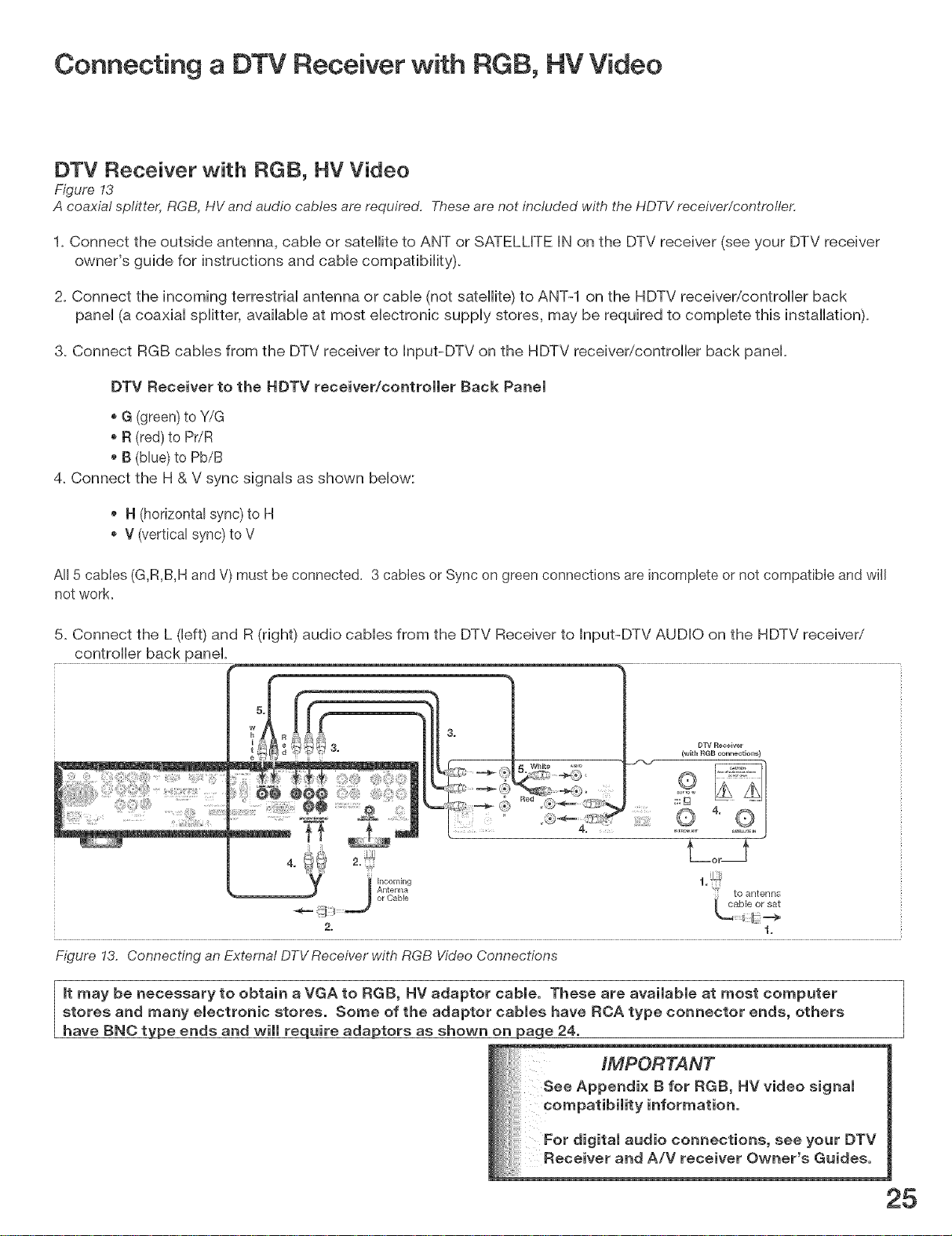
DTV Receiver with RGB, HV Video
Figure 13
A coaxial splitte_ RGB, HV and audio cables are required. Theseare not included with the HDTV receiver/controller.
1. Connect the outside antenna, came or sateHke to ANT or SATELLITE IN on the DTV receiver (see your DTV receiver
owner's guide for instructions and cabHecompafibiHRy).
2. Connect the incoming terrestdaH antenna or cabHe (not sateHRe)to ANT-1 on the HDTV receiver/controller back
paneH(a coaxiaH spHRter,avaiHabHeat most eHectronic suppHy stores, may be required to compHete this installation).
3. Connect RGB cables from the DTV receiver to Input-DTV on the HDTV receiver/controller back panel.
DTV Receiver to the BDTV receiver/controJJer Back Pane)
G (green) to Y/G
R (red) to Pr/R
B (blue)to Pb/B
4. Connect the H & V sync signals as shown below:
H (horizontal sync) to H
V (vertical sync) to V
All 5 cabies (G,R,B,H andV)must be connected. 3 cables or Sync on green connections are incomplete or not compatible and wiJJ
not work
5. Connect the L (left) and R (right) audio cables from the DTV Receiver to Input-DTV AUDIO on the HDTV receiver/
controller back panel.
DTV Receiver
(with RGB connections)
to antenns
2_ .1,
Figure !3. Connecting an External DTV Receiver with RGB VideoConnections
it may be necessary to obtain a VGA to RGB, HV adaptor cable. These are available at most computer
stores and many electronic stores. Some of the adaptor cables have RCA type connector ends, others
have BNC type ends and will require adaptors as shown on p_ge 24.
Connecting a DVD Player with Component Video or a
Display Monitor with Component Video
DV[::) PJayer with Component Video
Figure 14
Component video cabtes and audio cables are required. Theseare not included with the HDTVreceiveffcontrotler.
1_Connect the Component Video cabHesfrom _1Pr/Pb VIDEO OUT on the back of the DVD pHayerto COMPONENT-
1 on the HDTV receiver/controller back paneH,matching the correct connection:
Y to Y (Green), Pr to Pr (Red), Pb to Pb (Btue)
2_ Connect a set of audio caMes from AUDIO OUT on the back of the DVD pHayerto COMPONENT-1 AUDIO Input
on the HDTV receiver/controller back panel The red cabHeconnects to the R (right) channeH, and the white cabHe
connects to the L (left) channel
IMPORTANT
ppendix B for component
signal compatibility
For digital audio connections, see
your DVD Owner's Guides.
Figure 14. Connecting a DVD Player with Component Video
Note: NetCommand® will assume you connected your DVD pHayerto Component-1. If you add a second
DVD or use any other inputs for your DVD, this change must match in the NetCommand system. See Edit
NetCommand... in Chapter 3 for more information_
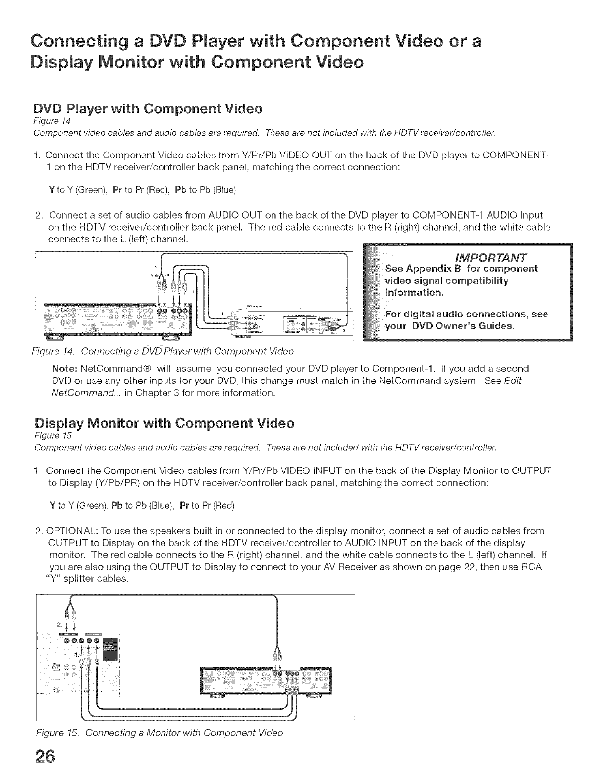
DispJay Monitor with Component Video
Figure 15
Component video cables and audio cables are required. These are not included with the HDTV receiver/controller.
1_ Connect the Component Video cables from Y/Pr/Pb VIDEO INPUT on the back of the Display Monitor to OUTPUT
to Display (Y/PbiPR) on the HDTV receiver/controller back panel, matching the correct connection:
Y to Y (Green),Pb to Pb (Blue), Pr to Pr (Red)
2_OPTIONAL: To use the speakers built in or connected to the display monitor, connect a set of audio cables from
OUTPUT to Display on the back of the HDTV receiver/controller to AUDIO INPUT on the back of the display
monitor. The red cable connects to the R (right) channel, and the white cable connects to the L (left) channel. If
you are also using the OUTPUT to Display to connect to your AV Receiver as shown on page 22, then use RCA
"Y" splitter cables_
Figure 15. Connecting a Monitor with Component Video
26
Connecting HDMI Devices
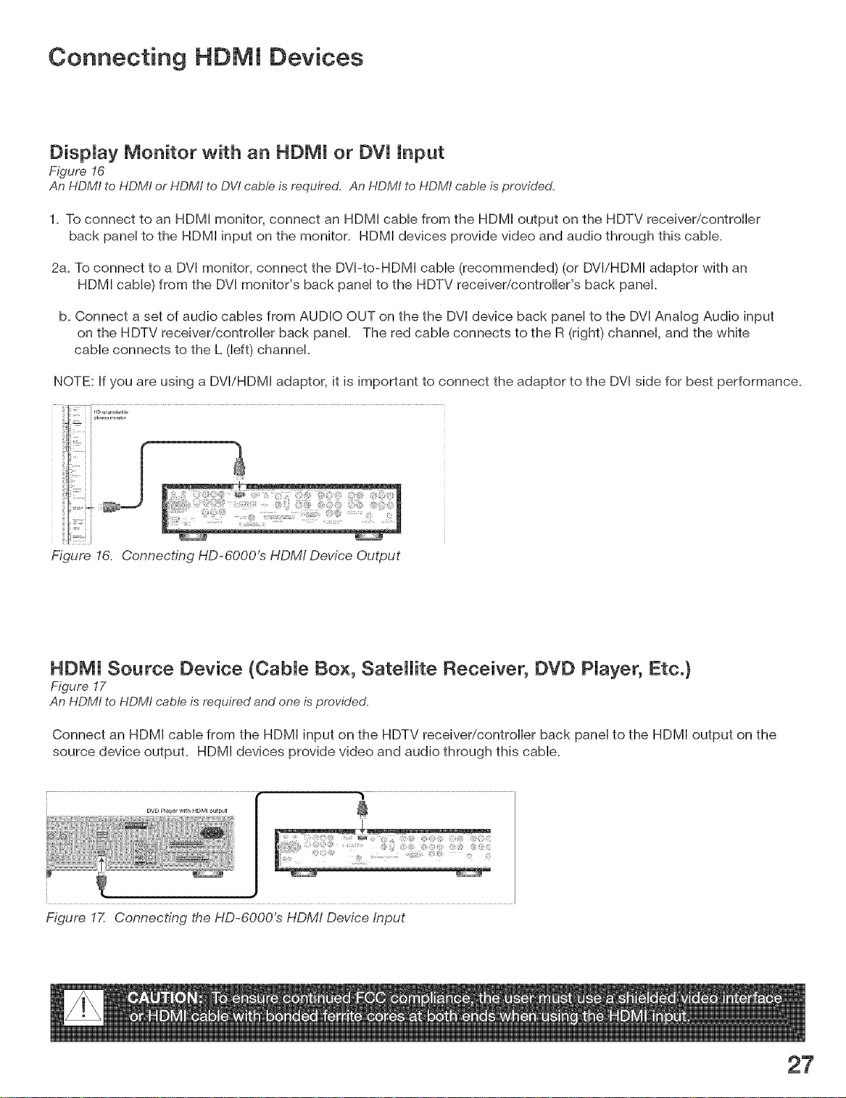
DispJay Monitor with an HDMI or DVi Input
Figure !6
An HDMI to HDMI or HDMf to DV/cable is required. An HDMI to HDMI cable isprovided,
1. To connect to an HDMI monitor, connect an HDMI cabHefrom the HDMI output on the HDTV receiver/controller
back paneHto the HDMI input on the monitor. HDMI devices provide video and audio through this cabHe.
2a. To connect to a DVI monitor, connect the DVI-to-HDMI came (recommended) (or DVI/HDMI adaptor with an
HDMI came) from the DVI monitor's back paneHto the HDTV receiver/controller's back panel
b. Connect a set of audio caMes from AUDIO OUT on the the DVI device back paneHto the DVI AnaHogAudio input
on the HDTV receiver/controller back panel. The red cable connects to the R (right) channel, and the white
cable connects to the L (left) channel.
NOTE: If you are using a DVIiHDMI adaptor, it is important to connect the adaptor to the DVI side for best performance.
,' i HD u_ ad_ble
Figure 16. Connecting HD-6OOO's HDMI Device Output
HDMI Source Device (CabJe Box, Satellite Receiver, DVD PJayer, Etc.}
Figure !7
An HDM! to HDMI cable is required and one is provided.
Connect an HDMI cable from the HDMI input on the HDTV receiver/controller back panel to the HDMI output on the
source device output. HDMI devices provide video and audio through this cable.
DVD Prayer w_thHDMI output
Figure IZ Connecting the HD-6OOO's HDMI Device Input
27
Connecting a DV[ Device
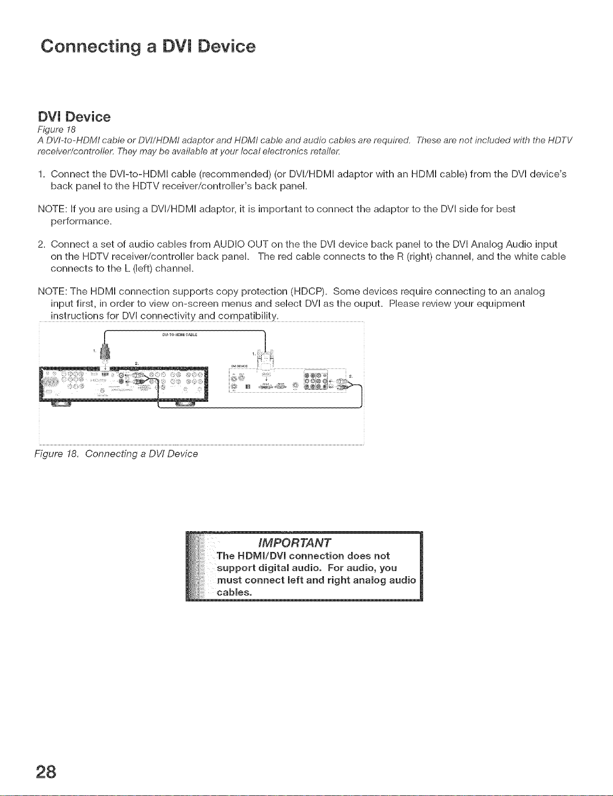
DV[ Device
Figure 18
A DV/-to-HDM/cable or DVt/HDMI adaptor and HDMI cable and audio cables are required, Theseare not included with the HDTV
receiver/controlle,c Theymay be available at your local electronics retailer.
1. Connect the DVPto-HDM[ cable (recommended) (or DV[/HDM[ adaptor with an HDM[ cable) from the DV[ device's
back panel to the HDTV receiver/controller's back panel.
NOTE: If you are using a DV[iHDM[ adaptor, it is important to connect the adaptor to the DV[ side for best
performance.
2. Connect a set of audio cables from AUDIO OUT on the the DV[ device back panel to the DV[ Analog Audio input
on the HDTV receiver/controller back panel. The red cable connects to the R (right) channel, and the white cable
connects to the L (left) channel.
NOTE: The HDM[ connection supports copy protection (HDCP). Some devices require connecting to an analog
input first, in order to view on-screen menus and select DV[ as the oupuL Please review your equipment
instructions for DV[ connectivity and compatibility.
Figure 18. Connecting a DW Device
28

Connecting to the Mitsubish LT=4260 LCD TV
Power Connection
Figure 19
TheAC Power cord is provided with the LT-4260,
Connect the AC power cord from the back of the HD-6000 to the back of the LT-4260. Make this connection before
connecting any devices. If you connect new devices after the power is connected, you will need to un@ug and
reconnect the AC power cord.
Figure 19. Power Connection to LT-4260
HDMJ Connection
Figure 20
An HDMI to HDM! cable is required and one isprovided,
Connect an HDMJ cane from the HDMI output on the HDTV receiver/controller back paneHto the HDMI/MonitorLink TM
Input on the LT-4260. HDMI devices provide video and audio through this cane.
f
__
@@e ........
Figure 20. HDMI Connection to LT-4260
Authorized Card Reader Connection
Figure 21
A USBA to USB B cable to connect the authorized card readers is provided with the LT-4260,
The USB A connects to the Authorized Card Reader port on the HD-6000. The USB B connects to the Authorized Card
Reader for the HD-6000 port on the LT-4260. You can then use the media card slots on the front of the LT-4260 with
authorized media cards.
Figure 21. HDM! Connection to LT-4260
USB B
29
Connecting the Emitter NetCommand ®
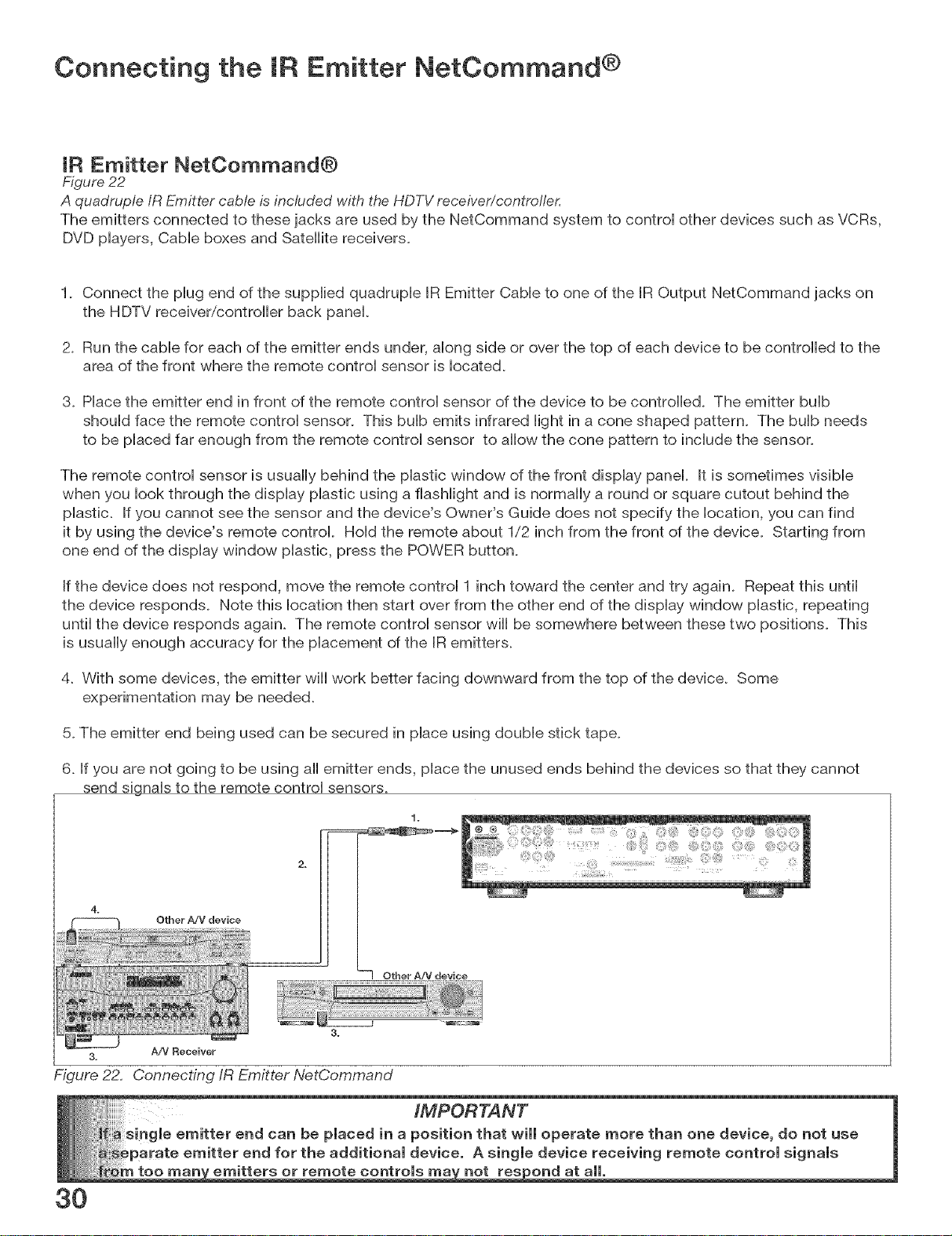
IR Emitter NetCommand®
Figure 22
A quadruple/R Emitter cable is included with the HDTV receiver/controller,
The emitters connected to these jacks are used by the NetCommand system to controi other devices such as VCRs,
DVD phyers, Cabb boxes and Satellite receivers.
1_ Connect the phg end of the suppibd quadrupb BREmitter Cabb to one of the IR Output NetCommand jacks on
the HDTV receiver/controller back panel
2_ Run the cabb for each of the emitter ends under, abng side or over the top of each device to be controlled to the
area of the front where the remote controi sensor is bcated.
3_ Phce the emitter end in front of the remote controi sensor of the device to be controHed. The emitter buib
shouid face the remote controi sensor. This bub emits infrared light in a cone shaped pattern. The bulb needs
to be placed far enough from the remote control sensor to allow the cone pattern to include the sensor.
The remote control sensor is usually behind the plastic window of the front display panel. It is sometimes visible
when you look through the display plastic using a flashlight and is normally a round or square cutout behind the
phstic. If you cannot see the sensor and the device's Owner's Guide does not specify the location, you can find
it by using the device's remote control Hold the remote about 1/2 inch from the front of the device. Starting from
one end of the display window plastic, press the POWER button.
If the device does not respond, move the remote control 1 inch toward the center and try again. Repeat this until
the device responds. Note this location then start over from the other end of the display window plastic, repeating
until the device responds again. The remote control sensor wiii be somewhere between these two positions. This
is usually enough accuracy for the placement of the IR emitters.
4. With some devices, the emitter wiii work better facing downward from the top of the device. Some
experimentation may be needed.
5. The emitter end being used can be secured in place using double stick tape.
6. If you are not going to be using all emitter ends, place the unused ends behind the devices so that they cannot
send signals to the remote control sensors.
===_
Other A/V device
-'70therA!V device
3.
3. A/V Receiver
Figure 2£ Connecting/R Emitter NetCommand
3O
too
emitters or remote controls not respond at all.
 Loading...