

Mitsubishi HD-6000 Service manual
20052005
2005
20052005
SerSer
Ser
SerSer
vicevice
vice
vicevice
MITSUBISHI ELECTRIC
ManualManual
Manual
ManualManual
SET TOP BOX
V26S CHASSIS
MODEL
HD-6000
CAUTION:
Before servicing this chassis, it is important that the service person read the "SAFETY PRECAUTIONS" and
"PRODUCT SAFETY NOTICE" contained in this manual.
SPECIFICATIONS
• Power Input : AC 120V, 60Hz
• Power Usage : 82W
• Frequency Range : VHF 54 ~ 470MHz
UHF 470 ~ 806MHz
Analog Cable - 1 ~ 125
Digital Cable - 1 ~ 135
• Antenna Input : 2 RF 75Ω unbalanced
• Tuning : 1 NTSC/A TSC/QAM
1 CableCARD™ Slot
1 NTSC for PIP
• Cabinet Dimensions : 17"(W) x 3.4"(H) x 16.8"(D)
• Weight : 27 lbs
• PVR : 120 GB Hard Disc
Approx. 12 hrs HD Recording
72 hrs SD Recording
• Analog Input : VIDEO IN JACK (RCA T ype)
Levels 1.0Vp-p 75Ω unbalanced
: AUDIO IN JACK (RCA T ype)
-4.7dBm 43kΩ unbalanced
: S-VIDEO IN JACK
(Y/C separate type)
Y:1.0 Vp-p C:0.286Vp-p(BURST)
75Ω unbalanced
: COMP / Y , Cr, Cb (RCA T ype)
Y: 1.0 Vp-p Cr, Cb: 700mVp-p
: A TV / Y(G), Pr(R), Pb(B), H, V
Y: 1.0Vp-p with sync 75Ω (BNC)
Pr, Pb: 700mV 75Ω
H, V: 3.0Vp-p 75Ω
: VGA / R,G ,B,V ,H (15 pin D)
• Output Level : VIDEO OUT JACK (RCA T ype)
1.0Vp-p 75Ω unbalanced
: COMP / Y ,Cr ,Cb
Y: 1.0 Vp-p Cr, Cb: 700mVp-p
: AUDIO OUT JACK (RCA T ype)
-4.7dBm 4.7kΩ unbalanced
• Digital : IEEE-1394 I/O Jacks
Interface : AC-3 Digtal Audio Output
: HDMI™ Input/Output
: MonitorLink
: CableCARD™ Slot
: NetCommand®
TM
Control/RS-232C
• Design specifications are subject to change without notice.
MITSUBISHI DIGITAL ELECTRONICS AMERICA, INC.
9351 Jeronimo Road, Irvine, CA 92618-1904
Copyright © 2005 Mitsubishi Digital Electronics America, Inc.
All Rights Reserved
.


MODEL: HD-6000
CONTENTS
INTRODUCTION ................................................................................................................................5
PRODUCT SAFETY NOTICE .............................................................................................................5
SAFETY PRECAUTIONS ...................................................................................................................6
PWB-LOCA TIONS .............................................................................................................................7
DISASSEMBL Y .................................................................................................................................. 7
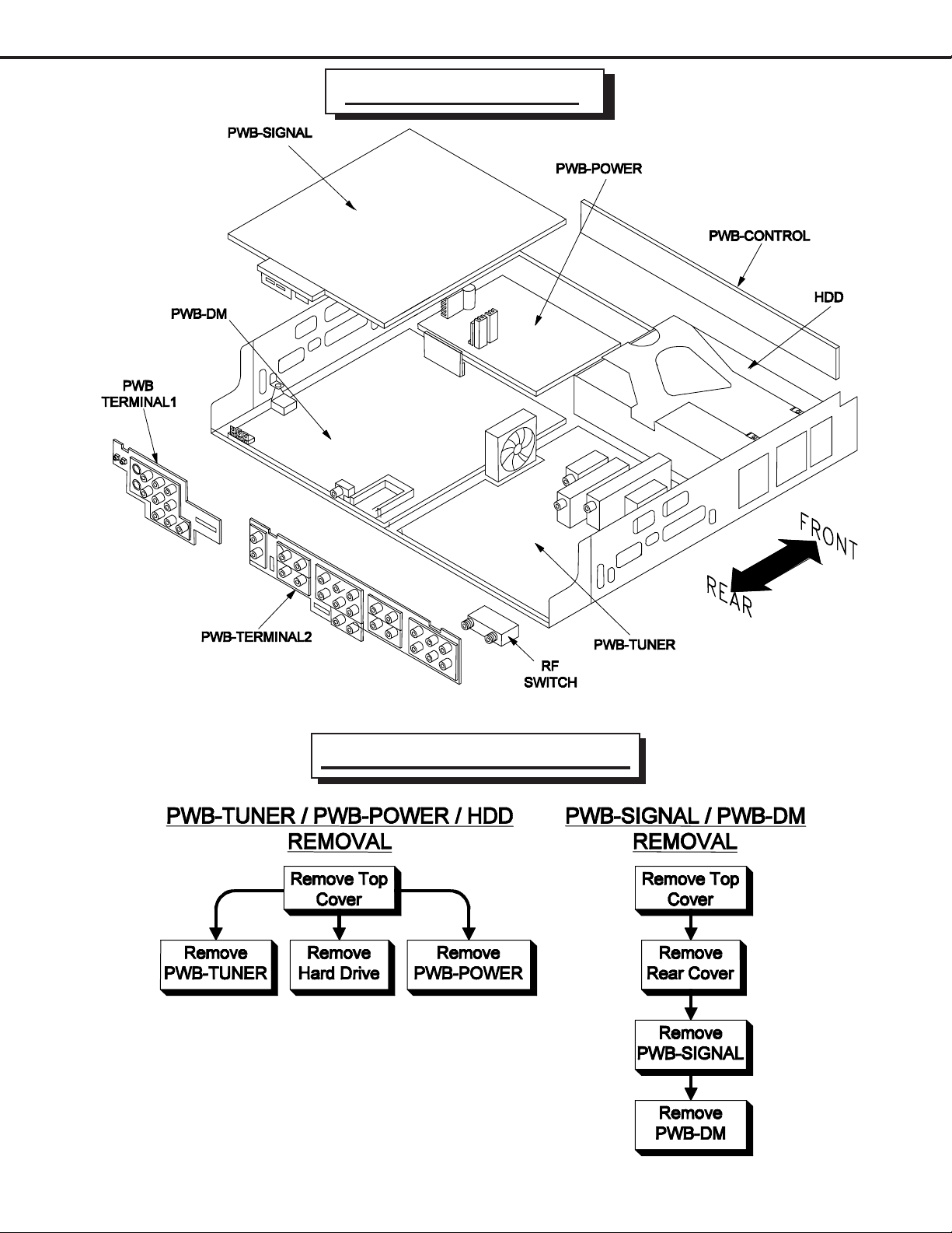
Disassembly Procedures Sequence ......................................................................................7
T op Cover removal ..................................................................................................................8
HDD (Hard Drive) removal....................................................................................................... 9
PWB’S removal ...................................................................................................................10
ELECTRICAL ADJUSTMENTS ........................................................................................................ 11
Equipment .................................................................................................................................... 11
Option Menu / Initialization Defaults / AV Defaults......................................................................... 1 2
LED Diagnostics ........................................................................................................................... 13
Remote Control Operational Mode ................................................................................................13
Circuit Adjustment Mode ...............................................................................................................14
Transfering data ............................................................................................................................ 15
Adjustment Items List................................................................................................................... 15
Adjustment Procedures ................................................................................................................16
Test Points .......................................................................................................................... 16
Main-Y Gain......................................................................................................................... 16
Sub-Y Gain .......................................................................................................................... 17
Sub Picture Offset ...............................................................................................................17
CHIP P ARTS REPLACEMENT ......................................................................................................... 18
REPLACEMENT P ARTS .................................................................................................................. 19
Parts Ordering ..............................................................................................................................19
Critical and Warranty Parts Designation........................................................................................19
Parts T olerance Codes.................................................................................................................. 19
SERVICE PARTS LIST ....................................................................................................................20
CIRCUITRY BLOCK DIAGRAMS ..................................................................................................... 29
St andby Power Supplies ............................................................................................................... 29
PWB-DM Power Supplies ............................................................................................................. 30
PWB-SIGNAL Switched Power Supplies ......................................................................................30
Video Select Circuitry ...................................................................................................................31
Video Output Circuitry................................................................................................................... 32
Sync Signal Selection................................................................................................................... 33
Sync Signal Output Path .............................................................................................................. 34
Record Signal Path....................................................................................................................... 34
Sound Signal Path ........................................................................................................................35
Control Circuitry ............................................................................................................................ 36
Command Input Circuitry............................................................................................................... 37
Macrovision Detection................................................................................................................... 37
PWB-DM Signal Path ...................................................................................................................38
Page 3

MODEL: HD-6000
Part 2
Schematic Diagrams
CONTENTS Page
SCHEMA TIC DIAGRAMS
Overall PWB Interconnect Diagram .................................................................................................1
POWER / E2P / CONTROL / MV Decoder] ....................................................................................2
TERMINAL-1 / TERMINAL-2 [Inputs / Outputs] ...............................................................................3
SIGNAL-1 [Video Switch]................................................................................................................4
SIGNAL-2 [Decoder / Switch]..........................................................................................................5
SIGNALS-3 [Micro} .........................................................................................................................6
SIGNAL-4 [TVGO] ..........................................................................................................................7
SIGNAL-5 [MPEG Encoder]............................................................................................................8
SIGNAL-6 [HDMI RX] ...................................................................................................................... 9
SIGNAL-7 [HDMI TX]..................................................................................................................... 10
SIGNAL-8 [Video Output]............................................................................................................. 11
SIGNAL-9 [IR232] ......................................................................................................................... 12
TUNER-1 [ATSC / NTSC Tuner] .................................................................................................... 13
TUNER-2 [Main A TSC / NTSC Demodulators] ...............................................................................14
PWB LA YOUT DIAGRAMS .............................................................................................................. 15
Page 4

MODELS: HD-6000
INTRODUCTION
This service manual provides service instructions for STB model HD-6000 which uses the V26S chassis. Service
personnel should read this manual thoroughly before servicing these chassis.
This service manual includes:
1. Safety Precautions
2. Assembly and disassembly instructions.
3. Servicing printed circuit boards (PCBs).
4. Electrical adjustments.
5. Chip parts replacement procedures.
6. Circuit path diagrams.
The parts list section of this service manual includes:
1. Cabinet and screen parts.
2. Electrical parts.
Schematic and block diagrams of the above listed models are included in this service manual for better understanding
of the circuitry . PCB drawings are also included for easy location of p arts and test points.
PRODUCT SAFETY NOTICE
Many electrical and mechanical parts in television receivers have special safety related characteristics. These characteristics are often not evident from visual inspection nor can the protection afforded by them necessarily be obtained by
using replacement components rated for higher voltage, wattage, etc.
Replacement parts which have special safety characteristics are identified in this service manual.
Electrical components having such features are identified by shading on the schematic diagrams and by bold type in
the parts list of this service manual. and by marking on the supplementary sheet for this chassis to be issued subsequently. The replacement for any safety part should be identical in value and characteristics.
Page 5
MODELS: HD-6000
SAFETY PRECAUTIONS
NOTICE: Observe all cautions and safety related notes located inside the receiver cabinet and on the
receiver chassis.
WARNING:
1. Operation of this receiver outside the cabinet or with the cover removed presents a shock hazard
from the receiver's power supplies. Work on the receiver should not be attempted by anyone who is
not thoroughly familiar with the precautions necessary when working on high voltage equipment.
2. When service is required, observe the original lead dress. Extra precaution should be taken to
assure correct lead dress in the high voltage area. Where a short-circuit has occurred, replace those
components that indicate evidence of overheating.
Leakage current check
Before returning the receiver to the customer, it is recommended that leakage current be measured according to the
following methods.
1. Cold Check
With the alternating current (AC) plug removed from the AC source, place a jumper across the two AC plug
prongs. Connect one lead of an ohm meter to the AC plug and touch the other lead to each exposed metal part
(i.e. antennas, handle bracket, metal cabinet, screw heads, metal overlay , control shaf ts, etc.), particularly any
exposed metal part that has a return path to the chassis. The resistance of the exposed metal parts having a
return path to the chassis should be a minimum of 1Mega Ohm. Any resistance below this value indicates an
abnormal condition and requires corrective action.
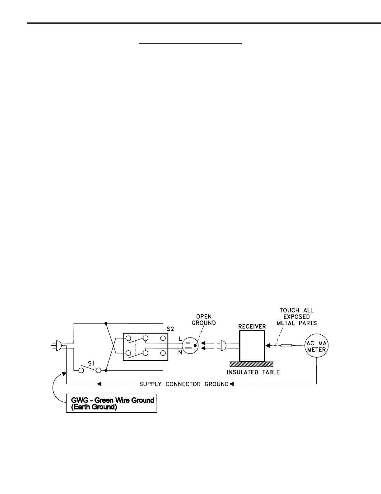
2. Hot Check ...Use the circuit shown below to perform the hot check test.
1. Keep switch S1 open and connect the receiver to the measuring circuit. Immediately after
connection, and with the switching devices of the receiver in their operating positions, measure
the leakage current for both positions of switch S2.
2. Close switch S1, energizing the receiver. Immediately af ter closing switch S1, and with the
switching devices of the receiver in their operating positions, measure the leakage current for both
positions of switch S2. Repeat the current measurements of items 1 and 2 after the receiver has
reached thermal stabilization. The leakage current must not exceed 0.5 milliampere (mA).
Page 6
MODELS: HD-6000
PWB LOCATIONS
Disassembly Sequence
Page 7
MODELS: HD-6000
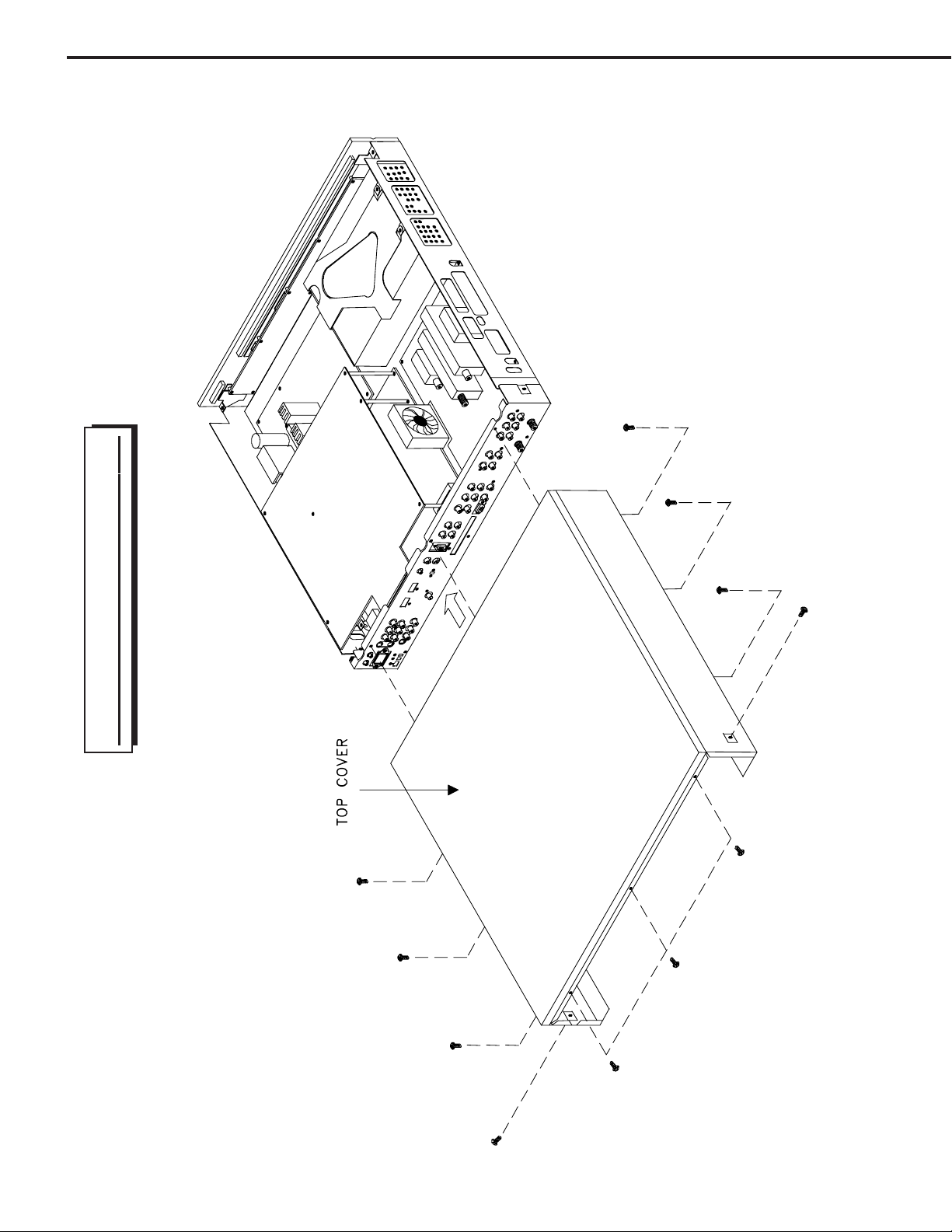
TOP COVER REMOVAL
Page 8
MODELS: HD-6000
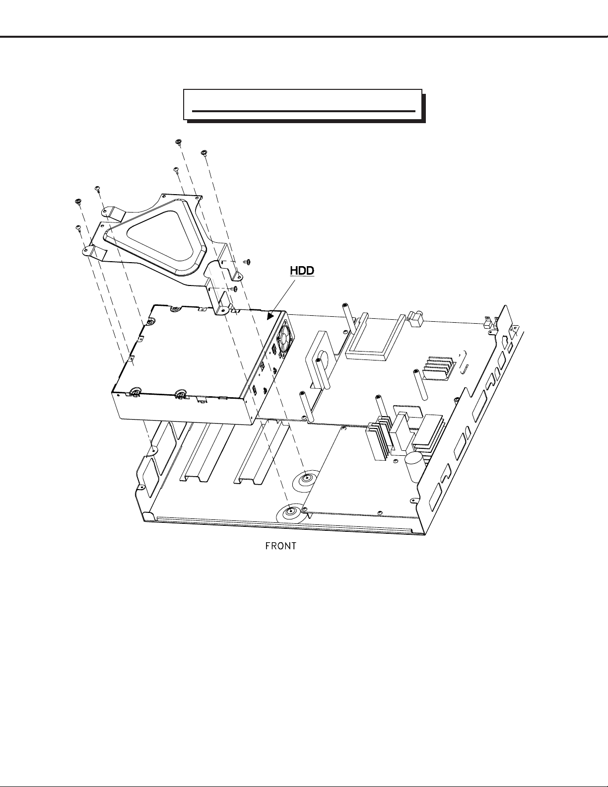
HDD (Hard Drive) Removal
NOTE: Prior to HDD replacement, perform the prodedure
“Replacing the HDD” described on page 15.
Page 9
MODELS: HD-6000
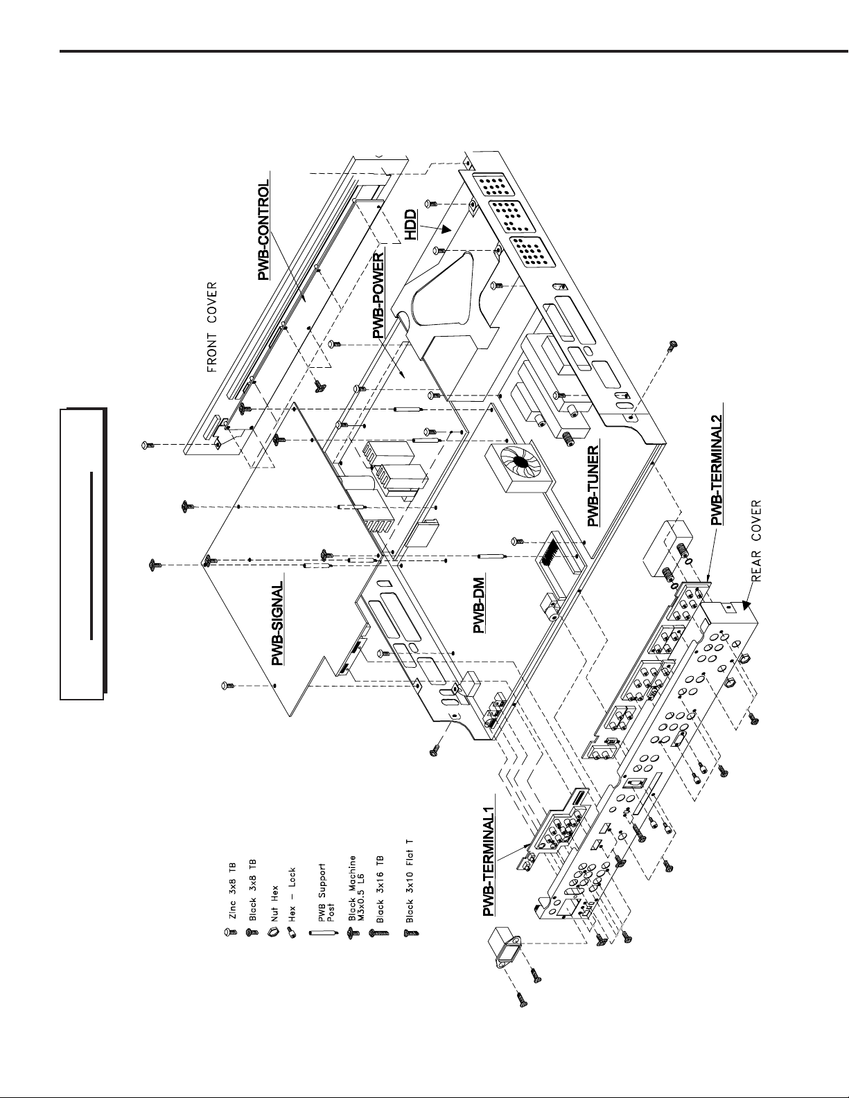
PWB Removal
Page 10
MODEL: HD-6000
ELECTRICAL ADJUSTMENTS
Note: Perform only the adjustments required.
Do not attempt an alignment if proper equipment is not available.
Test Equipment
• Oscilloscope (Unless otherwise specified, use 10:1 probes)
• Signal Generator (both SD and HD capable)
Test Signal
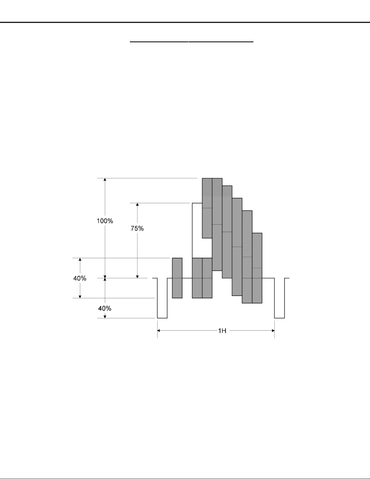
A. Color Bar Signal
Use the color bar signal shown below , unless otherwise specified in this manual.
Page 11
MODEL: HD-6000
V
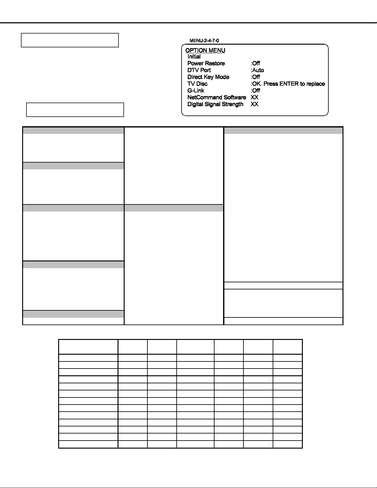
OPTION MENU
1. Press the “MENU” button on the remote hand unit.
2. Press the buttons “2”, “4”, “7” and “0” in order.
(The screen will change to the option menu.)
DEFAULTS
Defaults After Initialization
Audio / VideoCaptions Menu (continued)Setup Menu
Language :English Background :Gray A/V Memory Reset :Ant-1
Color Balance - - Digital Captions :On if Mute Audio
TV Pause :On Requ est Appear ance :Default Bas s :50%
Side Bar Color :Gray Digital S ettings Treble :50%
NetCommand Menu
Edit -- Size :Large Surround :Off
Transport Menu :On Color :W hite Sub W oofer :On
Default PVR -- Background :Black Listen To (Analog Only) :Stereo
Icon Order -- Opacity :Translucent Level Sound :On
Analog Quality :High Bac kground Opacity :Translucent Languag e (Digital Onl y) :English
Anten na Menu
Antenna :1 V-Chiip :Off Contrast :50%
Memorize -- TV Rating :TV-PG Brightness :50%
Prefer Digital -- FV-Fantasy Violence :Enable Sharpness :50%
Channel :3 D-Sexual Dialog :Enable Color :50%
Memory :Deleted L-Adult Language :Enable Tint :50%
Name -- S-Sexua l Situations :Enable Video noise :Standard
SQV -- V-Violence :Enable Film Mode (Auto) :On
Time Menu
Clock Setting :Manual Movie Rat ing :PG Fix/Variable :Variable
Time :12:00AM V-Chip Time Scan Rate Setting :Automatic
Date :1/01/00 Start :12:00pm
Time Zone :Eastern Stop :12:00pm PIP Sourc e :A nt-1 003
Daylight Savings Time :Applies Lock by Time PIP Position :Lower Right
Timer -- Lock by Time :Off POP Pos ition :Right Half
Captions Menu
Analog Captions :On if Mute Unlock Time :12:00pm
Font :Font 3 Balance :50%
V-Chip Lock Menu
Programs Not Rated :Enable Video Mute :On
Lock Time :12:00pm
Video
TV Volume
PIP/POP Format
Format
:30%
:Double Window
:Stretch
A/V Re se t Defaults
A/V Function Ant 1/2 Input 1/2
Contrast Center Center Center Center Center Center
Brightness Center Center Center Center Center Center
Sharpness
Color Center Center Center Center Center C enter
Tint Center Center Center Center Center C enter
ideo noise
Film Mode (Auto) On On On N/A On N/A
Bass
Treble
Balance Center Center Center Center Center Center
Surround
Listen To
Level Sound On On On On On On
NOTE: Front Panel A/V Reset, resets all A/V Memory settings.
Center Center Center N/A Center C enter
Standard Standard Standard N/A Standard N/A
Center Center Center Center Center Center
Center Center Center Center Center Center
Off Off Off Off Off Off
Stereo N/A N/A N/A N/A N /A
User Menu A/V Reset, resets only the selected input A/V settings.
Component
1/2/DTV
Page 12
VGA HDMI 1394
MODEL: HD-6000
A. A/V Memory
Each of the external inputs has its own Audio/Video Memory. A change in an A/V setting at a specific input is
stored in memory for that specific input.
B. A/V Reset
1. Press the GUIDE and FORMA T buttons on the front panel to reset all A/V Memories to default.
2. The AV Reset in the user’s menu initializes only the selected input’s A/V Memory.
LED Indicator Diagnostics
The “POWER/TIMER” LED provides an indication of the sets operation, and the possible cause of a malfunction.
1. Initial Control Circuitry Check
Immediately after the TV is connected to an AC power source:
LED Indi c a tions Cond itions Probable C a use
Off After AC is applied Standby Power Supply or TV µPC not running
Fast Bllink for 70 sec. After AC is applied Normal DM µPC is booting up
Fast Blink (doesn't stop) After AC is applied DM µPC failed to boot up
Slow Blink Set in Off Normal - Timer is set for Automatic Turn ON
2. Error Code Operational Check
Note: The Set T op Box must be in “Shut Down” and not have been switched Of f, to perform the Error Code
Operational Check. When the unit is switched Off, the code automatically resets to “12” No Error .
Pressing the front panel “DEVICE” and “MENU” buttons at the same time, and holding for 5 seconds,
activates the Error Code Mode. The LED flashes denoting a two digit Error Code, or indicating no problem
has occured since the last Initalization.
Note: The front panel buttons must be used, NOT those on the Remote Control.
• The number of flashes indicates the value of the MSD (tens digit) of the Error Code.
• The flashing then pauses for approximately 1/2 second.
• The LED then flashes indicating the value of the LSD (ones digit) of the Error Code.
• The Error Code is repeated a total of 5 times.
Example: If the Error Code is “35”, the LED will flash three times, pause, and then flash five times.
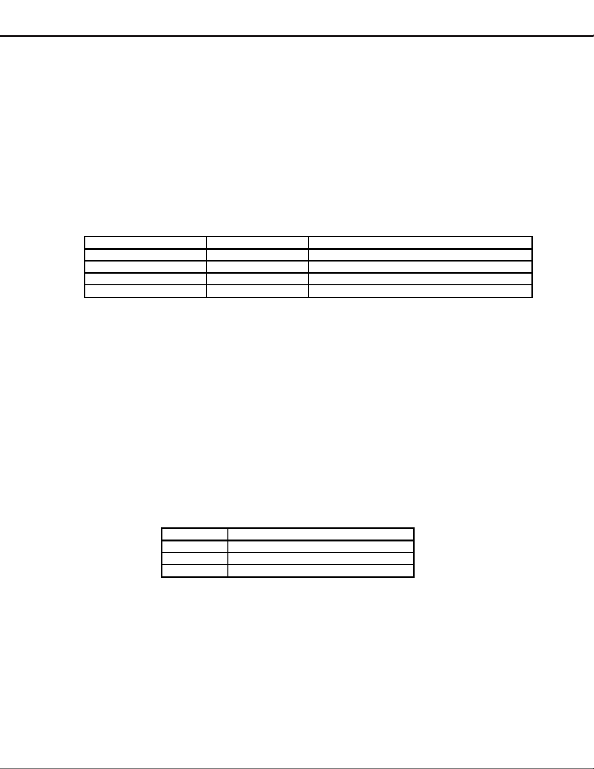
4. Error Codes
The Error Code designations indicating malfunction, or no malfunction, are listed below:
Error Code Probable Cause
12 Normal Operation - No Error Detected
35 Fan Stopped
41 Short Detected
Remote Control Operational Modes
There are two Remote Hand Unit Operational Modes, “Standard” and “NetCommandTM”. The Remote is initially
in the “Standard” mode. The “NetCommandT” mode is used when controlling Home Theater devices using
NetCommand. T o change the Remote Operational Mode:
• Set the Remote to the CABLE/DBS/DTV Layer.
• Point the Remote away from the STB.
• To change to “Netcommand” ... Hold the “Power” button and press “1-9-7” in sequence.
• To change to “S tandard” ... Hold the “Power” button and press “0-0-0” in sequence.
Page 13
MODEL: HD-6000
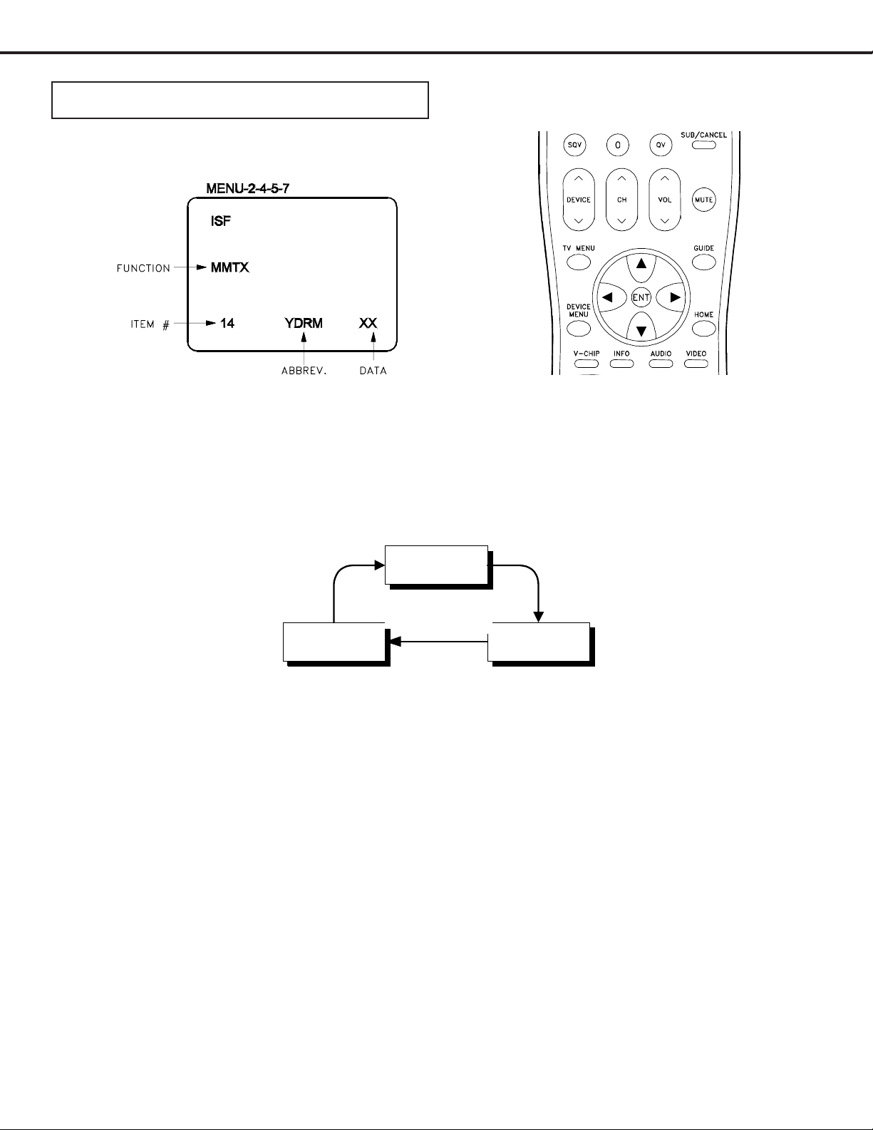
CIRCUIT ADJUSTMENTS
Electrical Adjustments
Electrical Adjusments are performed in Service Adjustment Mode.
1. Activating the adjustment mode
1. Press the “MENU” button on a remote hand unit.
(The “MENU” display will appear .)
2. Press the buttons “2”, “4”, “5” and “7” in that order . (The screen will change to the adjustment mode.)
If not changed to the adjustment mode, repeat steps 1 and 2.
2. Adjustment Function Selection
Use the “AUDIO” button to select a specific Adjustment Function.
AD9883A
Functions
SMTX MMTX
3. Adjustment Selection
Use the “VIDEO” button to select a specific elecrtrical ajustment.
4. Adjusting Data
After selecting an adjustment item, use the “UP” and “DN” buttons to change adjustment data.
ª If the “UP” button is pressed, the adjustment data increases.
ª If the “DN” button is pressed, the adjustment data decreases.
5. Saving data
Press “ENTER” to save the adjustment data in memory .
The display characters go red for approx. one second in this step.
Note: If the circuit adjustment mode is terminated without pressing
“ENTER”, changes in adjustment data are not saved.
6. T erminating the circuit adjustment mode
Press the “MENU” button on the remote hand unit twice to terminate the adjustment mode.
Note: The adjustment mode can be also terminated by turning the
power off.
Page 14
MODEL: HD-6000
A
Replacing the HDD
Prior to replacing the HDD Assembly , perform the following step s.
1 ) Disconnect all external IEEE1394 devices.
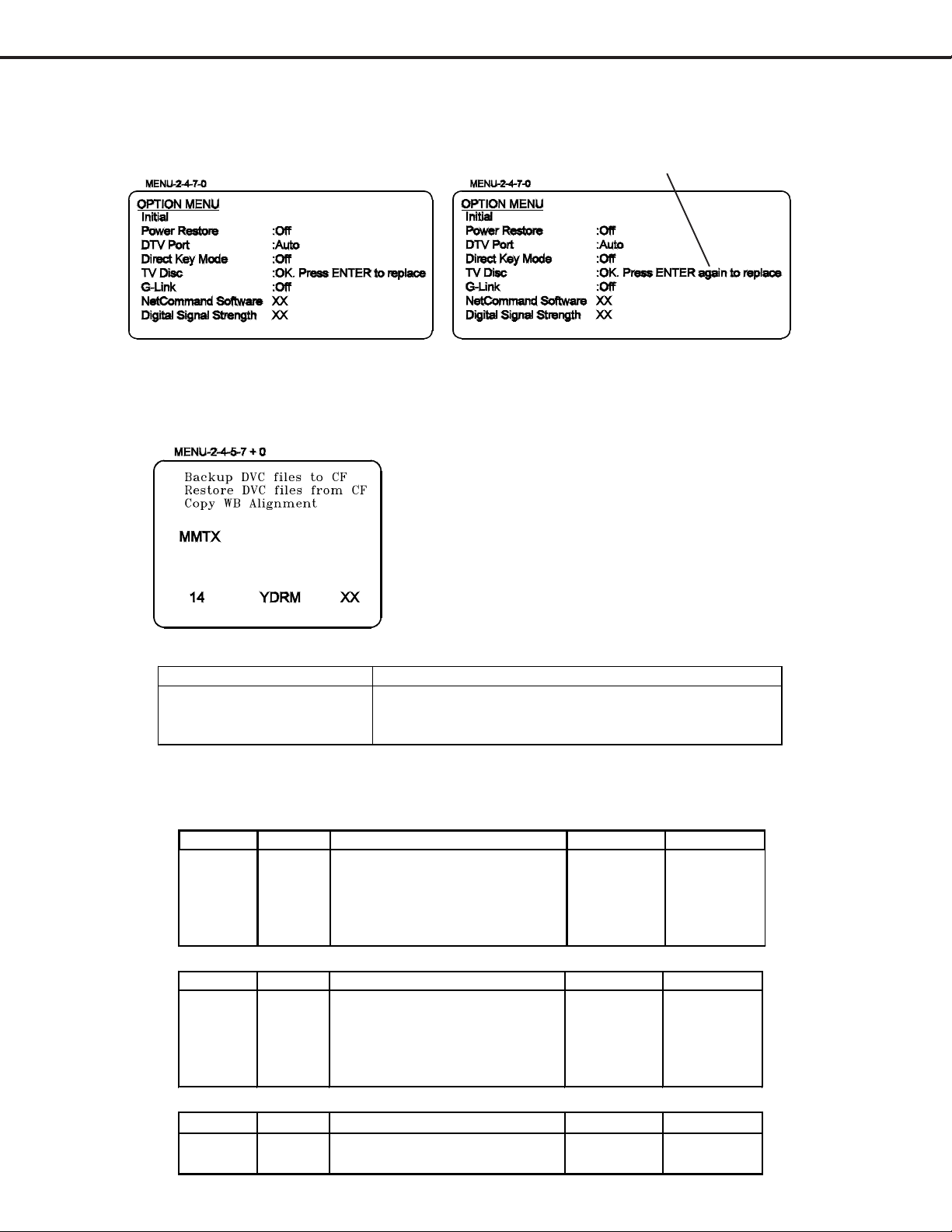
2 ) Enter the Option Menu ... Press “MENU-2-4-7-0”
3) Select TV Disc. Press “Enter.” Wait for confirmation and press “Enter” again.
Transferring Data
1 ) Enter the Service Adjustment Mode ... Press “MENU-2-4-5-7”
2 ) Press “0” when in the Service Mode ... Three choices appear at the top of the screen.
3 ) User UP & DN keys to highlight the desired choice, the Press “ENTER”
Data Transfer Defini tions
Display Description
Bac k up DVC files to CF Copies A li gnment dat a to c ompact flas h
Restore DVC files from CF Loads A lignm ent data from com pac t flash
Copy WB Alignment Used t o transfer WB data from si gnal E2P to DM E 2P
SERVICE MODE - Adjustment Items and Initial Data Values
MAIN MATRIX
Item # Abbrev. Descript ion Data Range Initial Data
1 TNTM Main Tint adjustment 0~63 28
4 COLM Main Color adjustment 0~63 20
14 YDRM Main Y gain control 0~31 5
18 UPDM Main Pb Pedestal adjustment 0~15 7
19 VPDM Main Pr Pedestal adjustment 0~15 7
SUB MATRIX
Item # A bbr ev. Desc ription Data Range Initial Data
1 TNTS Sub Tint adjustment 0~63 28
4 COLS Sub Color adjustm ent 0~63 18
14 YDRS Sub Y gain control 0~31 5
18 UPDS Sub Pb Pedestal adjustment 0~15 7
19 VPDS Sub Pr Pedestal adjustment 0~15 7
AD9883
Item # Abbrev. Description Data Range Initial Data
12 ROFF Red Offset 0~27 55
14 BOFF Blue Offset 0~27 59
Page 15
Measuring
Instrument
Test Point
Ext. Trigger
Measuring
Range
Input Signal
Input Terminal
MODEL: HD-6000
Purpose:
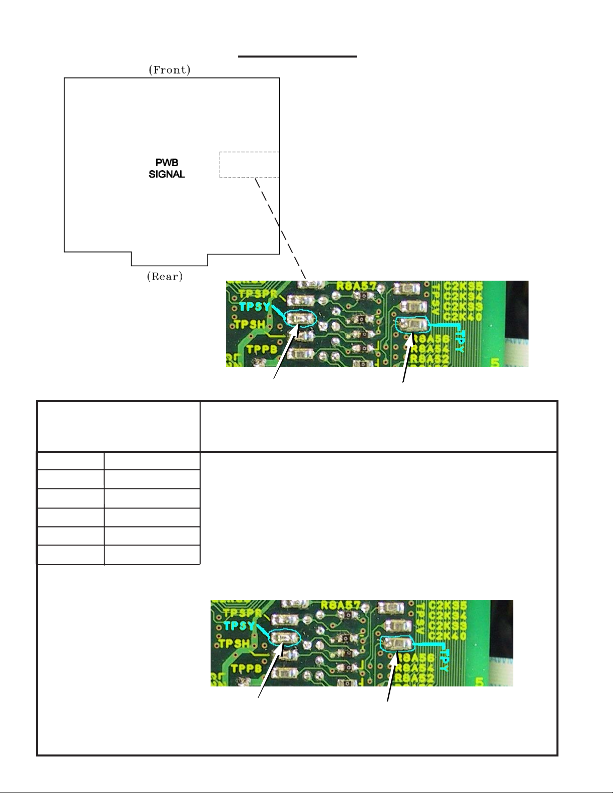
TEST POINTS
Symptom:
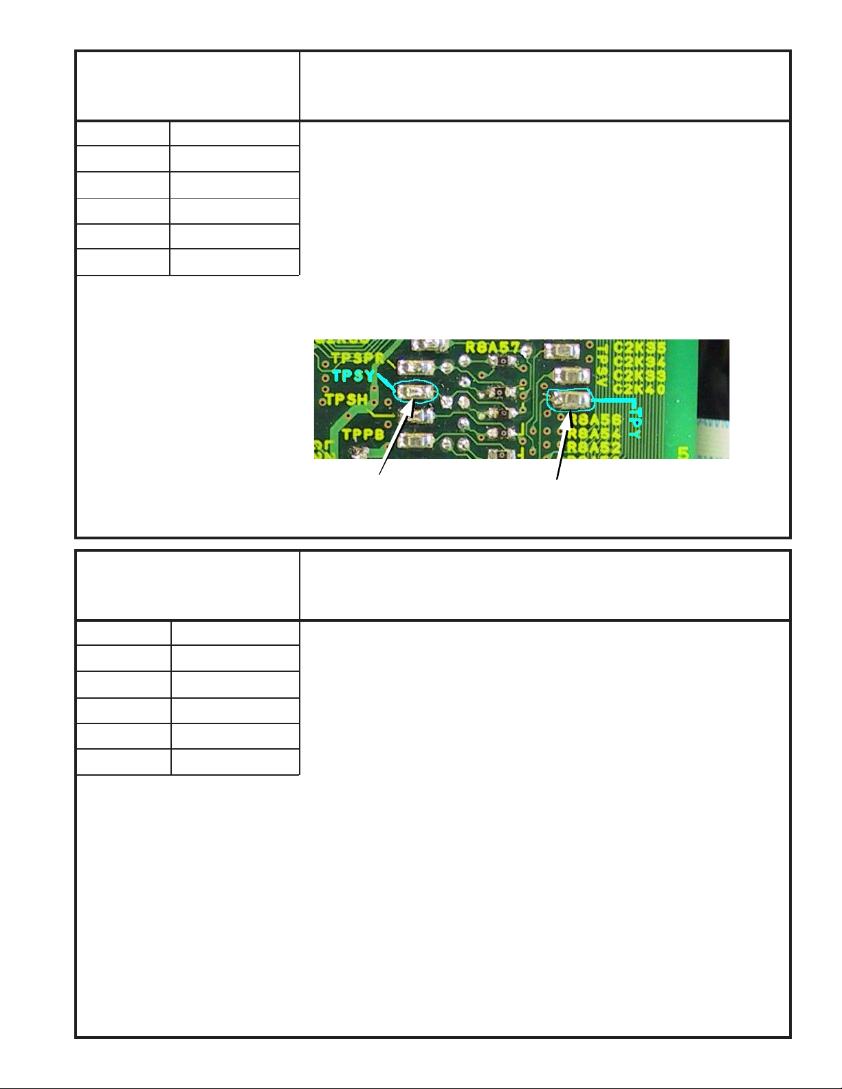
PWB-SIGNAL (Partial)
[Video Circuit]
1. Main-Y Gain
Measuring
Instrument
Test Point
Ext. Trigger
Measuring
Range
Input Signal
Input Terminal
Oscilloscope
TPY
------
------Color bars
External Input
TPSY
Purpose:
Symptom:
1. Supply a Color Bar pattern with 100% white signal to an External Input. Select
the Color Bars as the source (Device button).
2. Connect a scope to TPY (Main Luminance).
3. Enter the Alignment Mode (MENU-2-4-5-7)
4. Select the MMTX function (AUDIO button).
5. Select adjust item #14 YDRM (VIDEO button).
6. Set the data so the waveform at TPY is 0.7 Vp-p ±0.03 Vp-p (ADJUST buttons).
7. Press “ENTER” to save data.
8. Press “MENU” twice to exit the service mode.
T o set the main picture Y level
Incorrect analog source main picture brightness level.
TPY
PWB-SIGNAL (Partial)
TPSY
TPY
Page 16
[Video Circuit]
Purpose:
MODEL: HD-6000
To set the sub picture Y level
2. Sub-Y Gain
Measuring
Instrument
Test Point
Ext. Trigger
Measuring
Range
Input Signal
Input Terminal
Oscilloscope
TPY & TPSY
------
------Color bars
External Input
Symptom:
Incorrect analog source sub picture brightness level.
1. Supply a Color Bar pattern with 100% white signal to an External Input.
2. Select the Color Bars as the source for both the main and sub pictures.
2. Connect a scope to TPY (Main Luminance) & TPSY (Sub Luminance).
3. Enter the Alignment Mode (MENU-2-4-5-7)
4. Select the SMTX function (AUDIO button).
5. Select adjust item #14 YDRS (VIDEO button).
6. Set the data so the waveform at TPSY equals TPY. (ADJUST buttons).
7. Press “ENTER” to save data.
8. Press “MENU” twice to exit the service mode.
PWB-SIGNAL (Partial)
TPSY
TPY
[Video Circuit]
3. Sub Picture Offset
Measuring
Instrument
Test Point
Ext. Trigger
Measuring
Range
Input Signal
Input Terminal
----
----
------
------Full White Raster
External Input
Purpose:
Symptom:
T o match sub picture white to main picture white
Sub picture white differs from white in the main picture.
1. Supply a full white raster signal to an External Input.
2. Select the White raster as the source for both the main and sub pictures.
3. Use the PIP/POP buttion to select the Single PIP mode.
4. Enter the Alignment Mode (MENU-2-4-5-7)
4. Select the AD9883A function (AUDIO button).
5. Select item #12 ROFF and #14 BOFF (VIDEO button).
6. Set the data fore items #12 and #14 so the sub picture white is close to that in
the main picture. (ADJUST buttons).
7. Press “ENTER” to save data.
8. Press “MENU” twice to exit the service mode.
Page 17
 Loading...