

Page 1
2003
SerSer
Ser
SerSer
vicevice
vice
vicevice
MITSUBISHI ELECTRIC
ManualManual
Manual
ManualManual
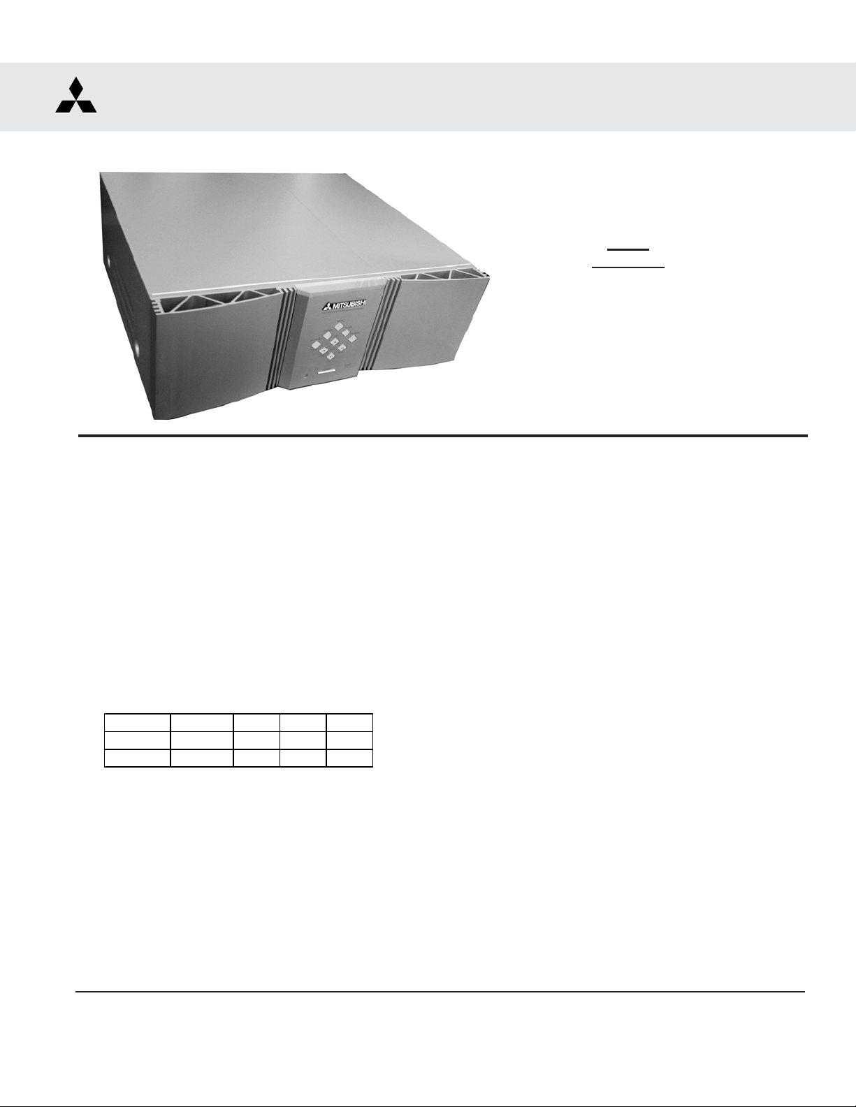
SET TOP BOX
V21S CHASSIS
V21S
MODELS
HD-5000
HD-5000A
CAUTION:
Before servicing this chassis, it is important that the service person read the "SAFETY PRECAUTIONS" and
"PRODUCT SAFETY NOTICE" contained in this manual.
SPECIFICATIONS
• Power Input : AC 120V, 60Hz
• Power Usage : 79W
• Frequency Range : VHF 54 ~ 470MHz
UHF 470 ~ 806MHz
• Antenna Input : VHF/UHF 75Ω unbalanced
2 - NTSC
1 - A TV/QAM
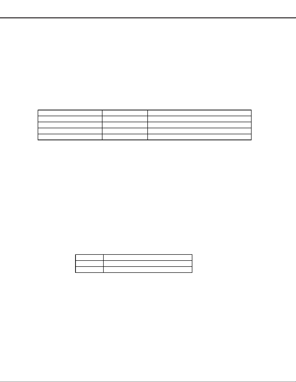
• Cabinet Weight and Demensions
Mode l W e ight Height W idth Depth
HD-5000
HD-5000A
19 lbs. 8" 17" 16"
19 lbs. 8" 17" 16"
• Input Level : VIDEO IN JACK (RCA T ype)
1.0Vp-p 75Ω unbalanced
: AUDIO IN JACK (RCA Type)
-4.7dBm 43kΩ unbalanced
: S-VIDEO IN JACK
(Y/C separate type)
Y:1.0 Vp-p C:0.286Vp-p(BURST)
75Ω unbalanced
: COMP / Y, Cr , Cb (RCA T ype)
Y: 1.0 Vp-p Cr, Cb: 700mVp-p
: ATV / Y(G), Pr(R), Pb(B), H, V
Y: 1.0Vp-p with sync 75Ω (BNC)
Pr, Pb: 700mV 75Ω
H, V: 3.0Vp-p 75Ω
: VGA / R,G ,B,V ,H (15 pin D)
• Output Level : VIDEO OUT JACK (RCA Type)
1.0Vp-p 75Ω unbalanced
: AUDIO OUT JACK (RCA Type)
-4.7dBm 4.7kΩ unbalanced
• Digital Interface
: IEEE-1394 I/O Jacks
: AC-3 Digital Audio Output
: MonitorLink
: MonitorLinkTM Control/RS-232C
: NetCommand
TM
/DVI
®
.
MITSUBISHI DIGITAL ELECTRONICS AMERICA, INC.
9351 Jeronimo Road, Irvine, CA 92618-1904
Copyright © 2004 Mitsubishi Digital Electronics America, Inc.
All Rights Reserved
Page 2

MODELS: HD-5000 / HD-5000A
CONTENTS
INTRODUCTION ................................................................................................................................5
PRODUCT SAFETY NOTICE ............................................................................................................. 5
SAFETY PRECAUTIONS ...................................................................................................................6
DISASSEMBLY
T op Cover Assembly / Disassembly ................................................................................................7
PCB Disassembly FlowChart..........................................................................................................7
PCB Assembly / Disassembly ........................................................................................................ 8
Cabinet Assembly / Disassembly ................................................................................................. 10
ELECTRICAL ADJUSTMENTS
Test Equipment ............................................................................................................................. 11
Initial Setup................................................................................................................................... 12
LED Indicator Diagnostics............................................................................................................. 13
Error Codes .................................................................................................................................. 13
Remote Control Operational Mode ................................................................................................13
Circuit Adjustment Mode ............................................................................................................... 14
On Screen Display Position Adjustment Mode.............................................................................. 15
Data Transfer Mode....................................................................................................................... 15
E2PROM Replacement................................................................................................................. 15
Adjustment Items List...................................................................................................................15
Adjustment Test Points................................................................................................................. 17
Adjustment Procedures ................................................................................................................18
Audio Circuit ........................................................................................................................ 18
Character Position ............................................................................................................... 19
Main/Sub Y Level................................................................................................................. 19
Color Alignment ................................................................................................................... 20
CHIP P ARTS REPLACEMENT ......................................................................................................... 21
REPLACEMENT PARTS
Parts Ordering ..............................................................................................................................22
Critical and Warranty Parts Designation........................................................................................ 22
Parts T olerance Codes.................................................................................................................. 22
Service Parts List.......................................................................................................................... 23
CIRCUITRY BLOCK DIAGRAMS
Standby Supplies Regulator..........................................................................................................32
DM Power Supply ......................................................................................................................... 33
Video / Color A/V Switch Circuit....................................................................................................34
Video / Color Signal Path..............................................................................................................35
Control Circuitry ............................................................................................................................ 36
Sound Circuitry ............................................................................................................................. 37
Sync Circuitry ............................................................................................................................... 38
Page 3
Page 3

MODELS: HD-5000 / HD-5000A
Section 2 .... Schematic Diagrams
SCHEMA TIC DIAGRAMS
Overall Block Diagram..................................................................................................................... 1
PCB-POWER / CONTROL / E2P.................................................................................................... 2
PCB-TERMINAL-1 [JACK] ..............................................................................................................3
PCB-TERMINAL-2-1 [SWITCH] ....................................................................................................... 4
PCB-TERMINAL-2-2 [3DYC] ........................................................................................................... 5
PCB-SIGNAL-1 [MICRO].................................................................................................................6
PCB-SIGNAL-2 [A V / IO].................................................................................................................7
PCB-SIGNAL-3 [VIDEO / CHROMA]............................................................................................... 8
PCB-SIGNAL-4 [IR / MV / DMP] ..................................................................................................... 9
PCB-2HDW-1 [IN] ......................................................................................................................... 10
PCB-2HDW-2 [MAIN].................................................................................................................... 11
PCB-2HDW-3 [OUT] ..................................................................................................................... 12
PCB-2HDW-4 [C720] HD-5000A ONLY ......................................................................................... 13
PCB-DEMOD................................................................................................................................14
PCB LA YOUT DIAGRAMS ............................................................................................................... 15
Page 4
Page 4

MODELS: HD-5000 / HD-5000A
INTRODUCTION
This service manual provides service instructions for the V21S STB chassis type. The specific models for each
chassis type are listed below. Service personnel should read this manual thoroughly before servicing these chassis.
V21S Ch a ssis
HD-5000
HD-5000A
This service manual includes:
1. Saftey Precautions
2. Assembly and disassembly instructions.
3. Servicing printed circuit boards (PCBs).
4. Electrical adjustments.
5. Chip parts replacement procedures.
6. Circuit path diagrams.
The parts list section of this service manual includes:
1. Mechanical and Cosmetic parts.
2. Electrical parts.
Schematic and block diagrams of the above listed models are included in this service manual for better understanding of the circuitry. PCB drawings are also included for easy location of parts and test points.
PRODUCT SAFETY NOTICE
Many electrical and mechanical parts in television receivers have special safety related characteristics. These
characteristics are often not evident from visual inspection nor can the protection afforded by them necessarily be
obtained by using replacement components rated for higher voltage, wattage, etc.
Replacement parts which have special safety characteristics are identified in this service manual.
Electrical components having such features are identified by shading on the schematic diagram and by bold
type in the parts list of this service manual. The replacement for any safety part should be identical in value
and characteristics.
Page 5
Page 5
MODELS: HD-5000 / HD-5000A
SAFETY PRECAUTIONS
NOTICE: Observe all cautions and safety related notes located inside the receiver cabinet and on the
receiver chassis.
WARNING:
1. Operation of this receiver outside the cabinet or with the cover removed presents a shock hazard
from the receiver's power supplies. Work on the receiver should not be attempted by anyone who is
not thoroughly familiar with the precautions necessary when working on high voltage equipment.
2. When service is required, observe the original lead dress. Extra precaution should be taken to
assure correct lead dress in the high voltage area. Where a short-circuit has occurred, replace those
components that indicate evidence of overheating.
Leakage current check
Before returning the receiver to the customer, it is recommended that leakage current be measured according to
the following methods.
1. Cold Check
With the alternating current (AC) plug removed from the AC source, place a jumper across the two AC plug
prongs. Connect one lead of an ohm meter to the AC plug and touch the other lead to each exposed metal
part (i.e. antennas, handle bracket, metal cabinet, screw heads, metal overlay, control shafts, etc.), particularly any exposed metal part that has a return path to the chassis. The resistance of the exposed metal parts
having a return path to the chassis should be a minimum of 1Mega Ohm. Any resistance below this value
indicates an abnormal condition and requires corrective action.
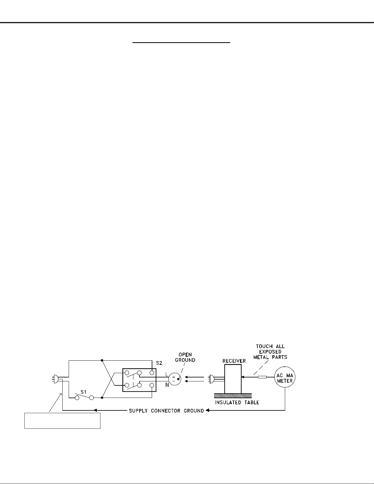
2. Hot Check ...Use the circuit shown below to perform the hot check test.
1. Keep switch S1 open and connect the receiver to the measuring circuit. Immediately after
connection, and with the switching devices of the receiver in their operating positions, measure
the leakage current for both positions of switch S2.
2. Close switch S1, energizing the receiver. Immediately after closing switch S1, and with the
switching devices of the receiver in their operating positions, measure the leakage current for both
positions of switch S2. Repeat the current measurements of items 1 and 2 after the receiver has
reached thermal stabilization. The leakage current must not exceed 0.5 milliampere (mA).
GWG - Green Wire Ground
(Earth Ground)
Page 6
Page 6
MODELS: HD-5000 / HD-5000A
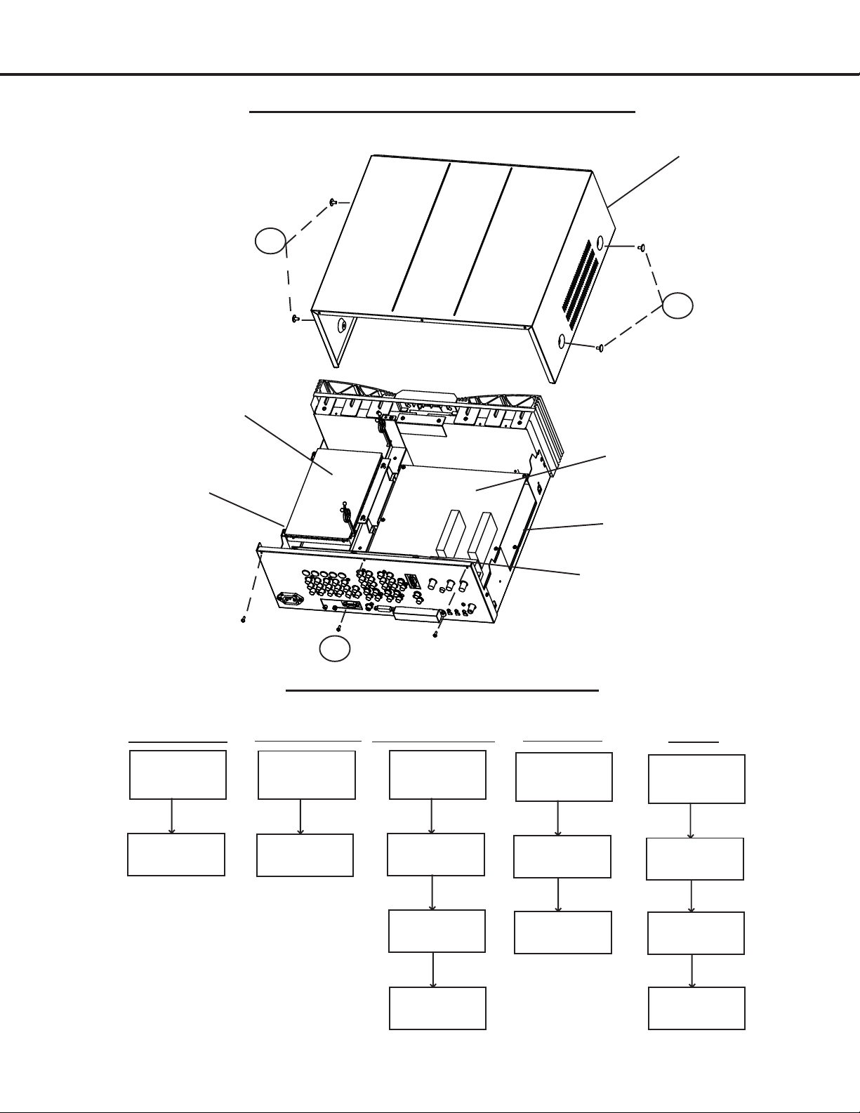
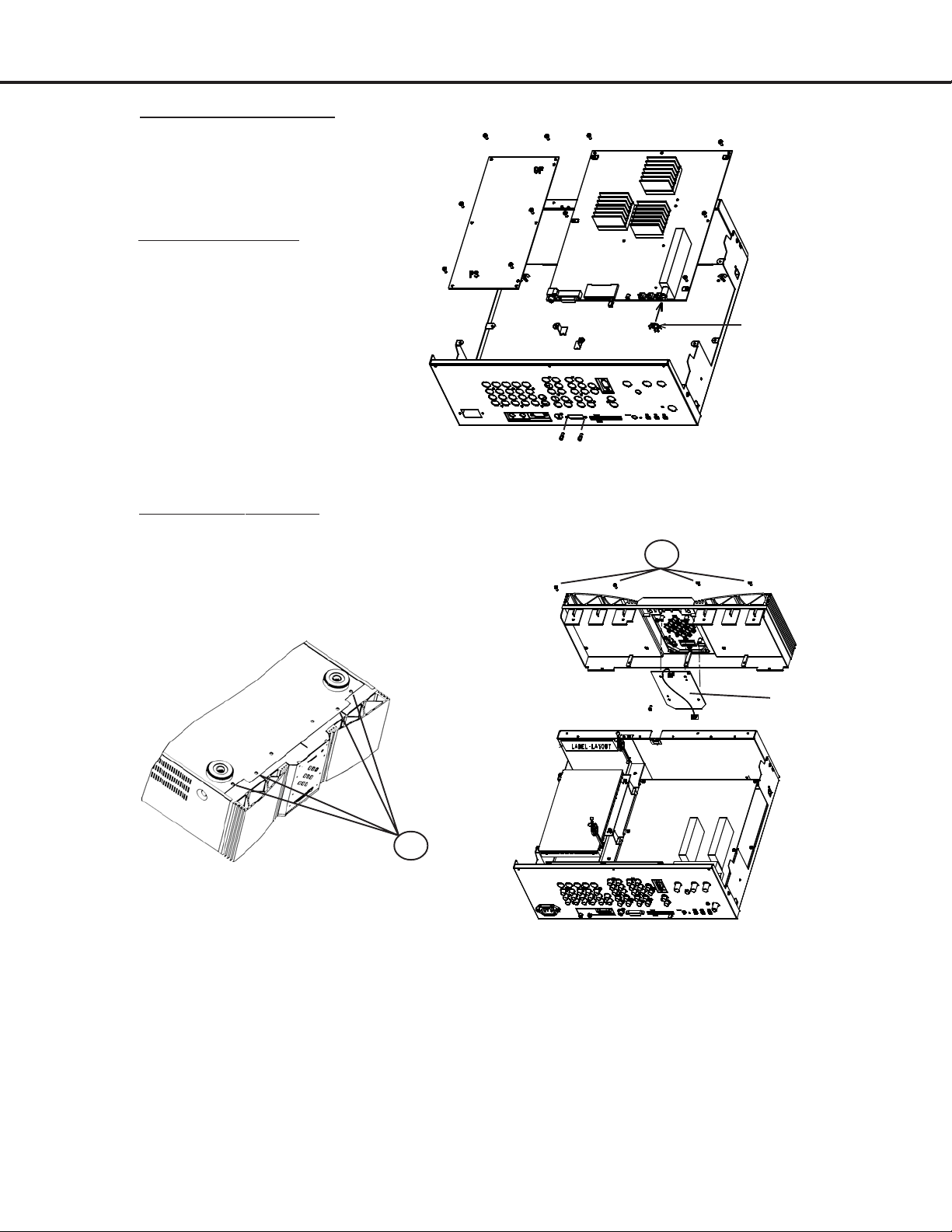
TOP COVER ASSEMBLY/DISASSEMBLY
1) Remove 3 SCREWS
2) Remove 4 SCREWS
2HDW PWB
POWER PWB
under 2hdw pwb
TOP COVER
2
2
SIGNAL PWB
DM PWB
under signal pwb
2HDW REMOV AL
REMOVE TOP
COVER
REMOVE 2HDW
PWB
1
PWB ASSEMBLY/DISASSEMBLY
(See detailed drawings on next 3 pages)
SIGNAL REMOV AL
REMOVE TOP
COVER
FOLLOW STEP #1
AND #2 TO REMOVE
SIGNAL PWB
TERMINAL REMOV AL
REMOVE TOP
COVER
REMOVE SIGNAL
PWB
REMOVE
TERMINAL PWB
POWER PWB
REMOVE 2HDW
REMOVE POWER
TERMINAL 1&2 PWB
REMOVE TOP
COVER
PWB
PWB
DM PWB
REMOVE TOP
COVER
REMOVE SIGNAL
PWB
REMOVE
TERMINAL PWB
SEPARATE
TERMINAL 1 AND
TERMINAL 2
PAGE 7
REMOVE DM PWB
Page 7
MODELS: HD-5000 / HD-5000A
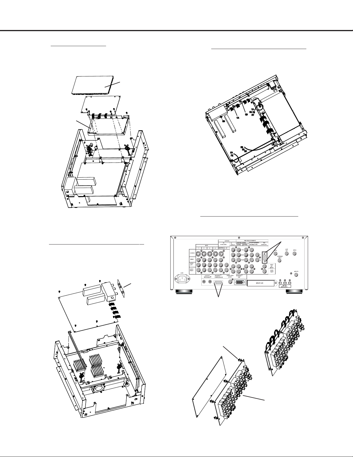
2HDW ASSEMBLY
1) Remove 3 connectors (EA, EB, EC) from Signal PWB
2) Remove 4 SCREWS from 2HDW PCB
SHIELD PLA TE
2HDW PWB
SHIELD CASE
EB
EC
EA
SIGNAL PWB ASSEMBY STEP 1
1) Remove 15 connectors (EA, EB,
EC, KE, KC, KB, CD, CA, VA,
DA, DV, VB, PE, PD, RF)
EA
EB
EC
SIGNAL PWB
RF
SIGNAL PWB ASSEMBY STEP 2
1) Remove 4 connectors (SU, ST , SS, SR)
2) Remove 6 SCREWS
3) Remove RF PLA TE
RF PLA TE
SU
ST
SS
SIGNAL PWB
SR
TERMINAL 1&2 PWB ASSEMBY
1) Remove 23 SCREWS (not shown)
2) Remove 4 HEX LOCK (H1~H4) screws
19
H3/H4
20
21
4
1
5
2
6
3
H1/H2
PWB SP ACER
7
10
15
11
8
12
13
9
18
16
17
14
23
22
PAGE 8
TERMINAL 1 PWB
TERMINAL 2 PWB
Page 8
MODELS: HD-5000 / HD-5000A
POWER PWB ASSEMBY
1) Remove 6 SCREWS from Power
PCB
1) Remove 2 connectors (GS, PS)
PE
PD
DM PWB ASSEMBY
1) Remove 5 SCREWS from DM
PCB
2) Remove 2 HEX LOCK SCREWS
3) Remove DTV W ASHER
3) Remove 7 connectors (DV, DA,
DB, VA, VB, PD, PE)
FRONT PWB ASSEMBY
1) Remove 4 SCREWS from bottom
2) Remove 4 SCREWS from top
3) Remove 1 connectors (RF)
4) Remove 4 SCREWS from FRONT PWB
POWER PWB
DA
VB
DV
DB
VA
DM PWB
DTV W ASHER
2
FRONT PWB
1
PAGE 9
Page 9
MODELS: HD-5000 / HD-5000A
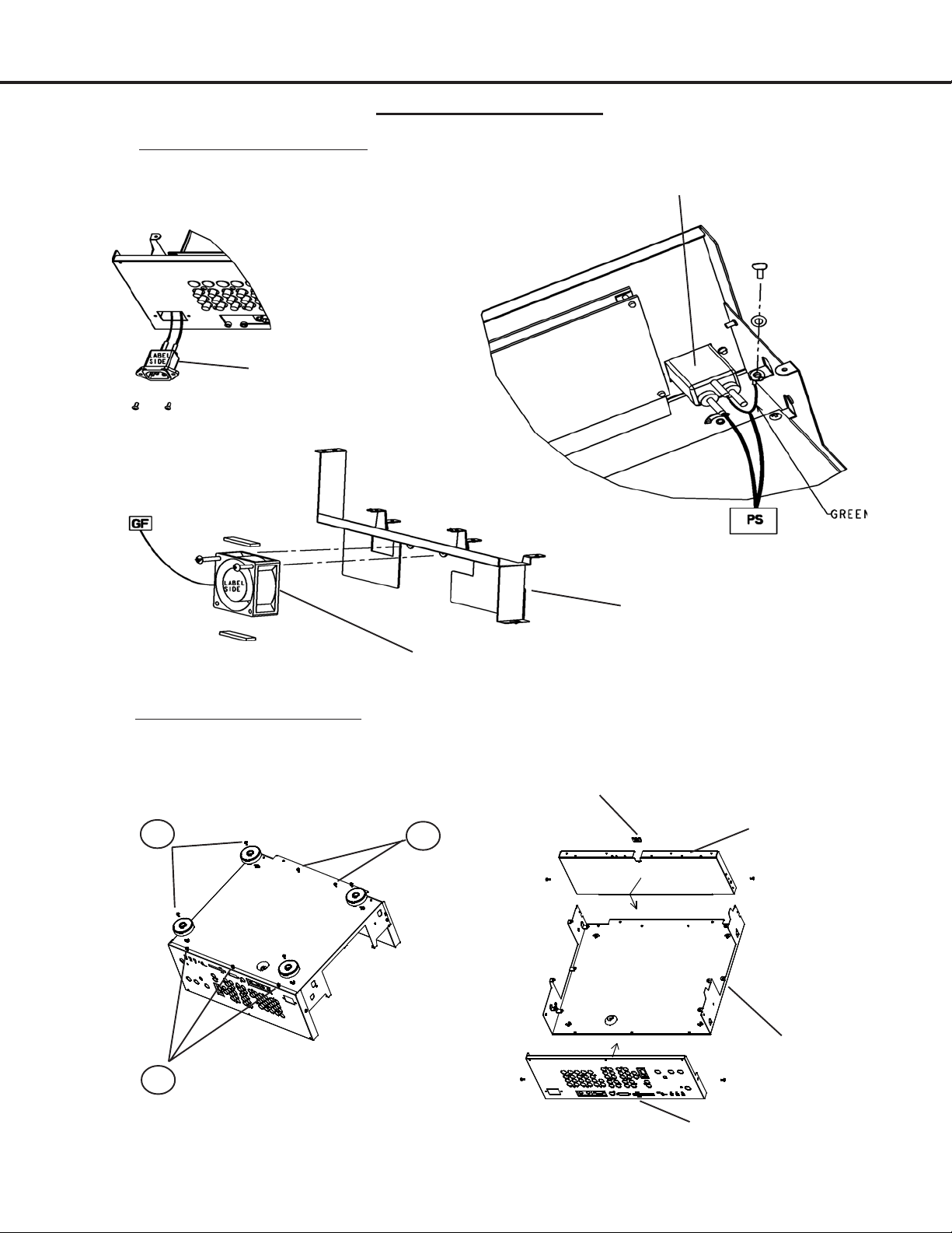
CABINET ASSEMBLY
AC INLET / F AN ASSEMBL Y
1) Remove AC INLET from rear panel
2) Remove F AN MOTOR from fan holder
AC INLET
AC INLET
F AN MOTOR
MAIN CHASSIS ASSEMBLY
1) Remove 4 SCREWS from bottom feet
2) Remove 3 SCREWS from rear panel bottom
3) Remove 2 SCREWS from cover shield bottom
1
1
3
F AN HOLDER
LEAD CLAMPER
COVER SHIELD
MAIN CHASSIS
2
REAR P ANEL
PAGE 10
Page 10
MODELS: HD-5000 / HD-5000A
4
ELECTRICAL ADJUSTMENTS
Note: Perform only the adjustments required.
Do not attempt an alignment if proper equipment is not available.
Test Equipment
• Oscilloscope (Unless otherwise specified, use 10:1 probes)
• Signal Generator (both SD and HD capable)
• Frequency Counter
• Direct Current Voltmeter
• Direct Current Power Supply
• Multiplex Audio Signal Generator
• Direct Current Ampere Meter
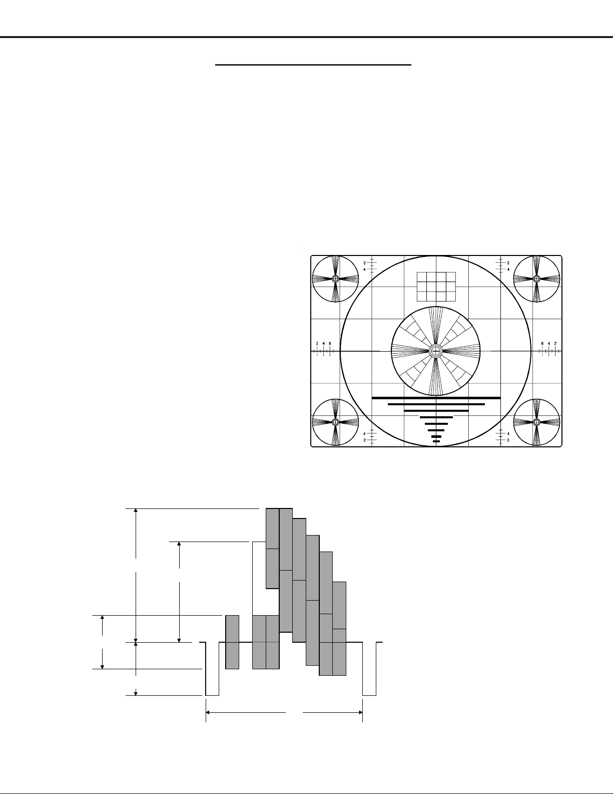
Test Signal
A. Monoscope Signal
Note: If you do not have
a monoscope signal source,
connect the unit to a VCR
and play a *Monoscope
alignment tape.
(* Part Number: 859C568060)
B. Color Bar Signal
Use the color bar signal shown
below, unless otherwise specified
in this manual.
100%
75%
0%
40%
1H
Monoscope Signal
Split-Field Color Bars (100% window)
Page 11
Page 11
MODELS: HD-5000 / HD-5000A
Initial Setup
A. Option Menu Setup
Follow the steps below for the initial set-up:
1. Move switch to ‘Cable/DBS/DTV’ layer
2. Select the "MENU" display by pressing the "MENU" button once.
3. Press the number buttons "0", "3", "7", "0" in sequence to select
the "OPTION MENU" display.
4. Press the "ADJUST" button to select "INITIAL."
5. Press "ENTER."
NOTE: At this time channel 3 is automatically selected.
B. Default Settings
SETUP CAPTI ONS AUD IO S ETT I NG S
Edit S et u p
Review CC Bac kground Gray Bas s 50%
Ant enna A () Enabled Digital Channel Guide Off Treble 50%
Ant enna B () Enabled Balanc e Center
Ant enna DTV () Enabled V-CHIP Off Surround Off
Input 1 () Enabled TV Rating TV-PG Listen to St ereo
Input 2 () Enabled FV-Fant as y V iol enc e () Enabled Level S ound O n
Input 3 () Enabled D-Sexual Di alog () Enabled
Input 4 () Enabled L-Adult Language () Enabled Contrast 50%
Component 1 () Enabled S-Sex ual S i tuat ion () Enabled Brightnes s 50%
Component 2 () Enabled V-Violence () Enabled Sharpness 50%
Input DTV () Enabled Program not Rat ed () Enabled Color 50%
VGA () Enabled Movie Rati ng PG Tint Center
Icon Posi tion
Transport Menu
Lang uage
ANTENNA
Ant enna ANT A Unlock Time N/A A udio Out to Dis play On
Mem oriz e Channels Air Lock Time N/A
Channel Ch-3
Mem ory Deleted Tim er Off S ourc e A nt A C h 3
CLOCK
Clock S et ting Manual Set Time 12:00P M PO P Pos it ion Right Half
Set Time 12:00 AM Devic e Ant -A Format St retc hed
Set Day Sunday Channel Ch-3 P IP/ P O P Form at Dble. Window
As above V -Chip St art Time 12: 00 P M Film Mode (A ut o) On
On V-Chip St op Time 12:00 P M V CR Com pens at ion St andard
Engli s h Video M ute On
MAI N M ENU DEFAULT S ETT I NGS
Closed Capt ions Wit h M ute Volum e 30%
V-CHI P P ARENT LO CK
V-CHI P L O CK BY TI M E
Lock By T i m e
Lock by Time Off Blac k Enhancement On
TIMER
Set Day Every day P IP Pos it ion Lower Right
Video Nois e St andard
A/V RESET DEFAULT SETTI NGS (By Input)
A/V M em ory Ant A/B Ant D T V Inp-DTV
INPUTS
1/2/3/4
Component
Contrast Center Center Center Center Center Center Center
Brightness Center Center Center Center Center Center Center
Sharpness Center Center Center Center Center N/A Center
Color Center Center Center Center Center Center Center
Tint Center Center Center Center Center Center Center
Vi deo Nois e S t andard N/A S t andard S t andard S tandard N/A N/ A
Film Mode(auto)
VCR C ompensat ion
On N/A On On On N/A N/A
Standard N/A Standard Standard Standard N/A N/A
Image Type Video N/A Vid eo V id eo Vi deo N/A N/ A
Bass Center Center Center Center Center Center Center
Tr eble Center Center Center Center Center Center Center
Balance Center Center Center Center Center Center Center
Surround OFF OFF OFF OFF OFF OFF OFF
Lis t en To Stereo E ngl ish N/A N/ A N/A N/ A N/ A
Page 12
(MENU-0-3-7-0)
OPTION MENU
Initial
P ow er re sto re :O F F
DTV Port :A uto
VIDEO SETTINGS
PIP/POP
1/2
VGA 1394
Page 12
MODELS: HD-5000 / HD-5000A
C. A/V Memory
Each of the external inputs has its’ own Audio/Video Memory. A change in an A/V setting at a specific input is
stored in memory for that specific input.
A/V Reset
1. The front panel AV Reset button initializes all A/V Memories.
2. The AV Reset in the user’s menu initializes only the selected input’s A/V Memory.
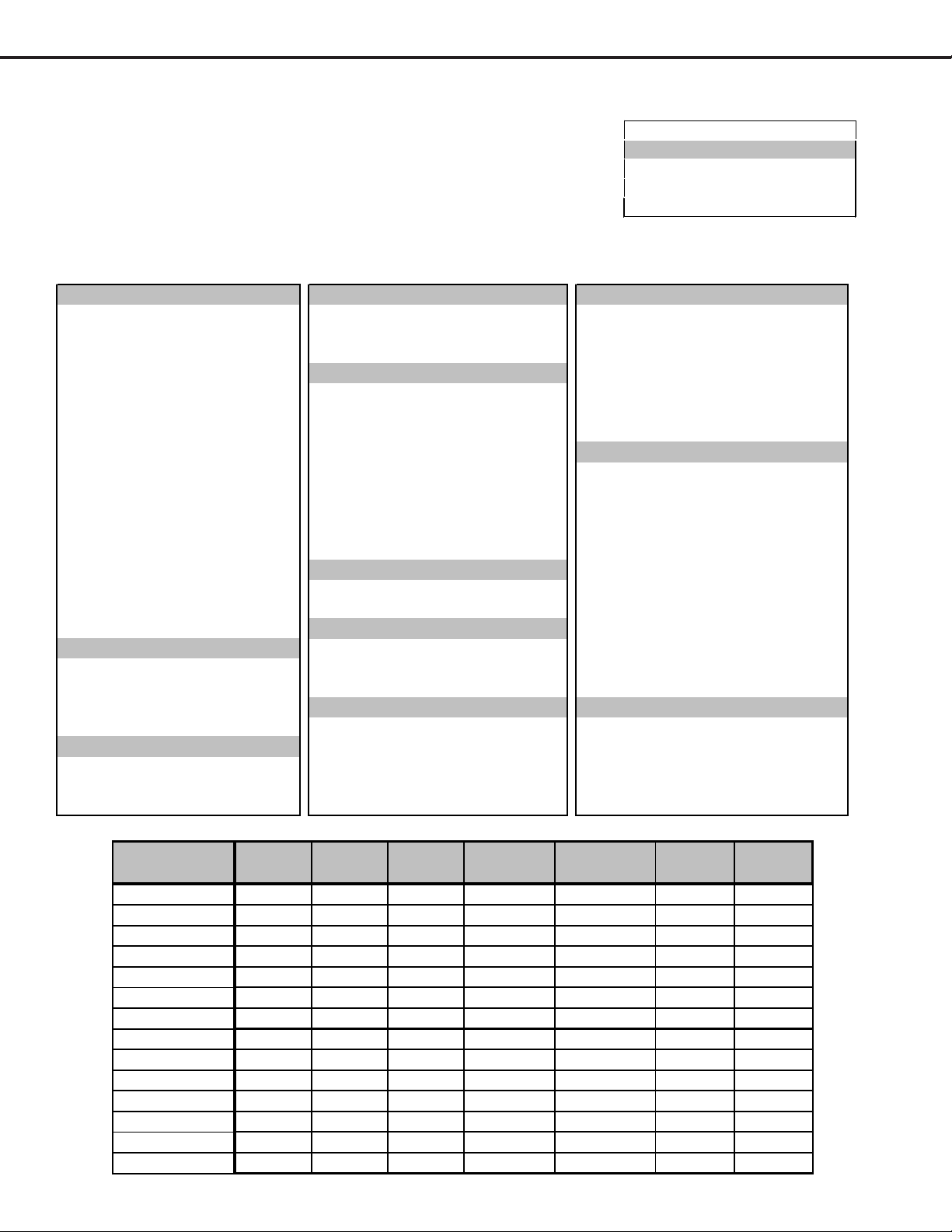
LED Indicator Diagnostics
The “Power ON LED” provides an indication of the sets operation, and the possible cause of a malfunction.
1. Initial Control Circuitry Check
Immediately after the TV is connected to an AC power source:
LED Indications Conditions Probable Cause
Off After AC is applied Standy P ower Suppl y or T V µP C not running
Fast Blink for 70 sec. A fter AC is appli ed Normal - DM µPC is booti ng up
Fast Bli nk ( doesn't stop) After A C is applied TV µPC is running, but DM failed to boot up
Slow Blink Set is Off Normal - Timer is set for Automatic Turn ON
2. Error Code Operational Check
Pressing the front panel “INPUT” and “MENU” buttons at the same time, and holding for 5 seconds,
activates the Error Code Mode. The LEDs flashes denoting a two digit Error Code, or indicating no problem
has occured since the last Initalization.
Note: The front panel buttons must be used, NOT those on the Remote Control.
• The number of flashes indicates the value of the MSD (tens digit) of the Error Code.
• The flashing then pauses for approximately 1/2 second.
• The LEDs then flash indicating the value of the LSD (ones digit) of the Error Code.
• The Error Code is repeated a total of 5 times.
Example: If the Error Code is “24”, the LEDs will flash two times, pause, and then flash four
times.
3. Error Codes
The Error Code designations indicating a malfunction, or no malfunction, are listed below:
Error Code Probable Cause
12 Normal Operation - No Error Detected
35 Fan Stop
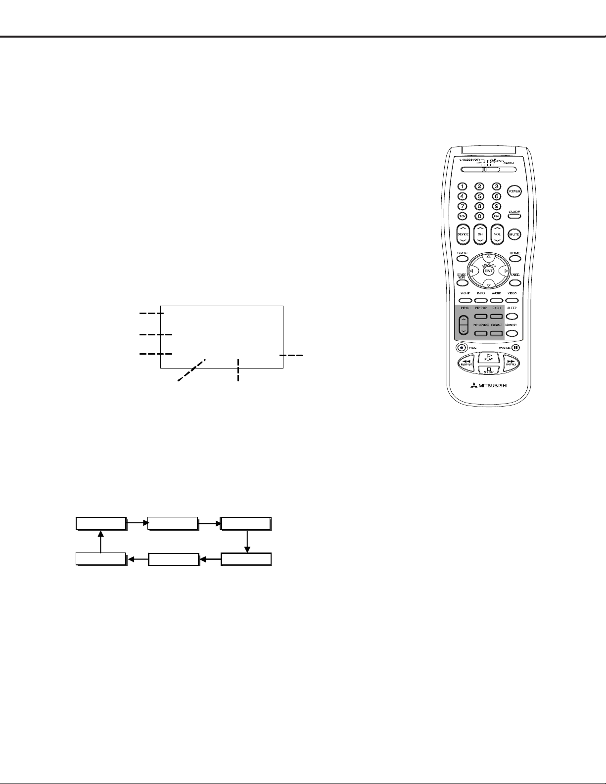
Remote Control Operational Modes
There are two Remote Hand Unit Operational Modes, “Standard” and “NetCommandTM”. The Remote is initially in
the “Standard” mode. The “NetCommandTM” mode is used when controlling Home Theater devices using
NetCommandTM. T o change the Remote Operational Mode:
• Set the Remote to the CABLE/DBS/DTV Layer
• Point the Remote away from the Set Top Box.
• T o change to “Netcommand
TM
” ... Hold the “Power” button and press “1-9-7” in sequence.
• T o change to “S tandard” ... Hold the “Power” button and press “0-0-0” in sequence.
Page 13
Page 13
MODELS: HD-5000 / HD-5000A
V
Circuit Adjustment Mode
Most of the adjustments can only be performed using the remote hand unit. Many of the adjustments must be
performed in both the 480i and 1080i modes. Video/Color adjustments must be performed in the 480i and
1080i modes, and data must be preset in the 480P (DVD) and VGA modes.
Note: Set the Remote Operational Mode to “NetCommandTM”. (Hold the “Power” button and press
“1-9-7” in sequence.) This slows the remote’s response and makes adjustments easier . When
adjustments are complete, set the Remote to its’ original Operational Mode.
A. Activating the Circuit Adjustment Mode
The current signal source determines if the
activated Adjustment Mode is 480i or 1080i.
1. Select the signal source (480i or 1080i).
2. Select ‘ Cable/DBS/DTV’ remote layer.
3. Press the "MENU" button on a remote hand unit.
4. Press the number buttons "0", "3", "5", "7" in sequence. The screen will
change to the Adjustment Mode.
Note: Repeat steps 1 and 2 if the circuit
adjustment mode does not appear
on screen.
CHAS SIS
MODE
ADJ ITEM
V21S
0
1 SC T 42 480i
ABBREV. DATA
SIGNAL
B. Selection of adjustment Functions and
Adjustment Items
To select an adjustment item in the circuit adjustment mode, first select the adjustment function that includes
the specific adjustment item to be selected. Then select the adjustment item. Refer to the following pages for
the listing of adjustment functions and adjustment items.
1. Press the "AUDIO" button on a remote hand unit to select an adjustment function. Each time the button
is pressed, the Function changes in the following sequence:
CJNGLMNTS
Adjustment Functions
VIDEO ADC
2. Press the “VIDEO” button to select a specific Adjustment Item. The Item number increases each time the
“VIDEO” button is pressed.
AUD SNTS
C. Changing Data
After selecting an adjustment Item, use the “ADJUST UP/DOWN” buttons to change data.
• Press “ADJUST DOWN” to decrease the data value.
• Press “ADJUST UP” to increase the data value.
D. Saving Adjustment Data
Press “ENTER” to save adjustment data in memory . The character display turns red for approximately one
second in this step.
Note: If the circuit adjustment mode is terminated without pressing “ENTER”, changes in adjustment data
are not saved.
Page 14
Page 14
MODELS: HD-5000 / HD-5000A
V
VGA
E. Terminating the Circuit Adjustment Mode
Press the “MENU” button on the remote hand unit twice to terminate the adjustment mode.
Note: The circuit adjustment mode can also be terminated by turning power OFF.
F. Toggle Between Reception Modes
Pressing “3” when in the Adjustment Mode VC Function toggles between 480i, 480p, 1080i and VGA.
However data changes are not automatically saved. Press “ENTER” to save data before pressing “3”.
On Screen Display Position Adjustment Mode
Activation
1. Select 480i or 1080i (DTV INPUT) source.
2. Press MENU-0-3-9-9
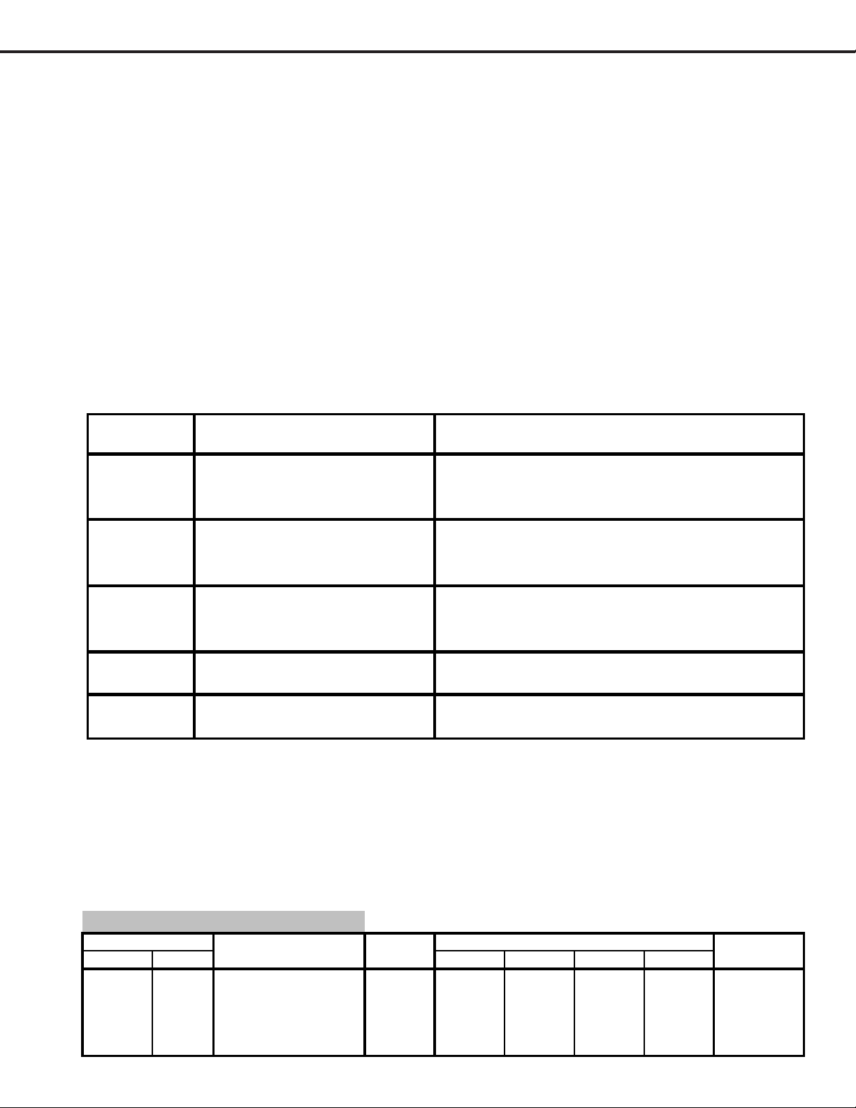
Data Transfer Mode
Activation
1. Pressing the “0” key when in the open alignment mode will access a special function table. The table
will be displayed at the top of the screen and below is description of the special functions available.
Key Sequence
Name Description
Transfers console alignment data (MNTS;SNTS;AUD)
1 2 XFER Console Data
stored on the Signal EEPROM to the DM E EPR O M .
Used when replacing a bad DM.
Transfers white balance alignment data (VC) stored on
1 3 XFER White Balance Data
the Signal EEPROM to the DM EEPR O M . Used when
replacing a bad DM .
Runs a check to confirm if a valid HAVI certificate has
1 4 Net check
been loaded. Status message will appear after pressing
the key sequence.
Transfers the alignment data stored in the DM EEPROM
1 6 Copy DM data to sig n al EEPRO M
to the signal EEPROM .
Transfers the alignment data stored in the signal
1 7 Copy signal data to DM
Note 1: After pressing the key sequence shown above, the special function table will disappear . The “0” key must be
pressed again to bring up the special function table.
EE P ROM to th e DM EEPROM .
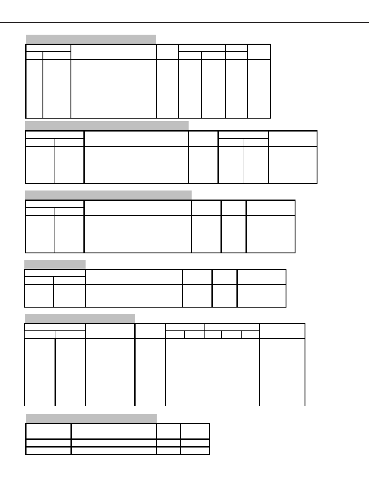
E2PROM Replacement
IC7A01 stores some adjustment data. After replacing the IC, set the data to the values given in the following
tables. If good performance is not obtained, perform the Adjustments Procedures given in the Notes column.
List of Adjustment Items.
C Function (Video Color) IC2V00
Function Display Adjustment Data Initial Data Notes
NO. Abbrev. Description Range 1080i 480i 480p
1SBRTSUB-BRIGHT 0~6353535353Sub Contrast
2 SCOL SUB-COL 0~15 9 9 9 9 Sub Color
3 STIN SUB-HUE 0~15 8 8 8 8 Sub Tint
4 SCON SUB-CON 0~15 7 7 7 7 Sub Contrast
26 D-PIC DYNAMIC PICTURE 0~3 1 1 1 1
Page 15
Page 15
MODELS: HD-5000 / HD-5000A
V
JNGL Function (Jungle) IC2V01
Display Adjustment Data 720P 1080i 480i Notes
No. Abbrev. Description Range HD HD HD
15 HPOS Horizontal Position 0~63 30 25 28 Center
16 BLKL Blanking on Left Side 0~63 15 5 26
17 BLKR Blanking on Rigth Side 0~63 35 46 42
18 BLKT
19 BLKB
38 HFRQ
Number of blanking lines after
Vsync (top blank)
Number of blanking lines
before Vsync (bottom blank)
Horizontal Frequency Control
0~63 32 32 37
0~63 26 26 27
0~255 125 26 3
MNTS Function (Main Decoder) IC2E00
Function Display Adjustment Data Notes
Item # Abbrev. Description Range RF Non RF
1 TNTM Main Tint 0~63 24 24 Preset
2 COLM Main Color 0~63 17 17 "
3 YDRM Main Gain Control 0~31 5 5 Main Y Level
4 VPDM Pr Pedestal Adjustment 0~15 7 7
5 UPDM Pb Pedestal Adjustment 0~15 7 7
Initial Data
SNTS Function (Sub Decoder) IC2H00
Function Display Adjustment Data Initial Notes
Item # Abbrev. Description Range Data
1 TNTS Sub Tint 0~63 26 Preset
2 COLS Sub Color 0~63 18 "
3 YDRS Sub Gain Control 0~31 5 Sub Y Level
4 VPDS Pr Pedestal Adjustment 0~15 7 "
5 UPDS Pb Pedestal Adjustment 0~15 7 "
AUDIO Function IC3A01
Function Display Adjustment Data Initial Notes
Item # Abbrev. Description Range Data
1 INP Input Level Alignment 0~15 8 Input Level
2 WDE Wideband Separator Align. 0~31 3 Separation
3 SPC Spectral Separator Align. 0~31 3 "
IDEO ADC IC53J6
Function Display Adjus tment Data Notes
Item # Abbrev. Description Range 1080i 480P 1080i 720P 480P
6 CPLC CLMPLACE 8 139 60 139 192 60
7 CDUR CLMPDUR 8 48 48 48 48 48
8 HWID HWIDTH 8 34 16 34 83 16
9 RGAI RED GAIN 8 160
10 GGAI GRN GAIN 8
11 BGAI BLUE GAIN 8
12 ROFS RED OFFSET 7
13 GOFS
14 BOFS BLUE OFFSET 7
GREEN OFFSET
7
Analog DVI
160 160 160 160
160 160 160 160 160
160 160 160 160 160
60 60
42 42
60 60
60 60 60
60 60 60
60 60 60
Color Alignment
"
"
"
"
"
OSD Horizontal Centering
Abbrev. Description Data Initial
OSDHD OSD POSITION FOR HD - 114249
OSDSD OSD POSITION FOR SD - 62754
(MENU-0-3-9-9)
Range Data
Page 16
Page 16
MODELS: HD-5000 / HD-5000A
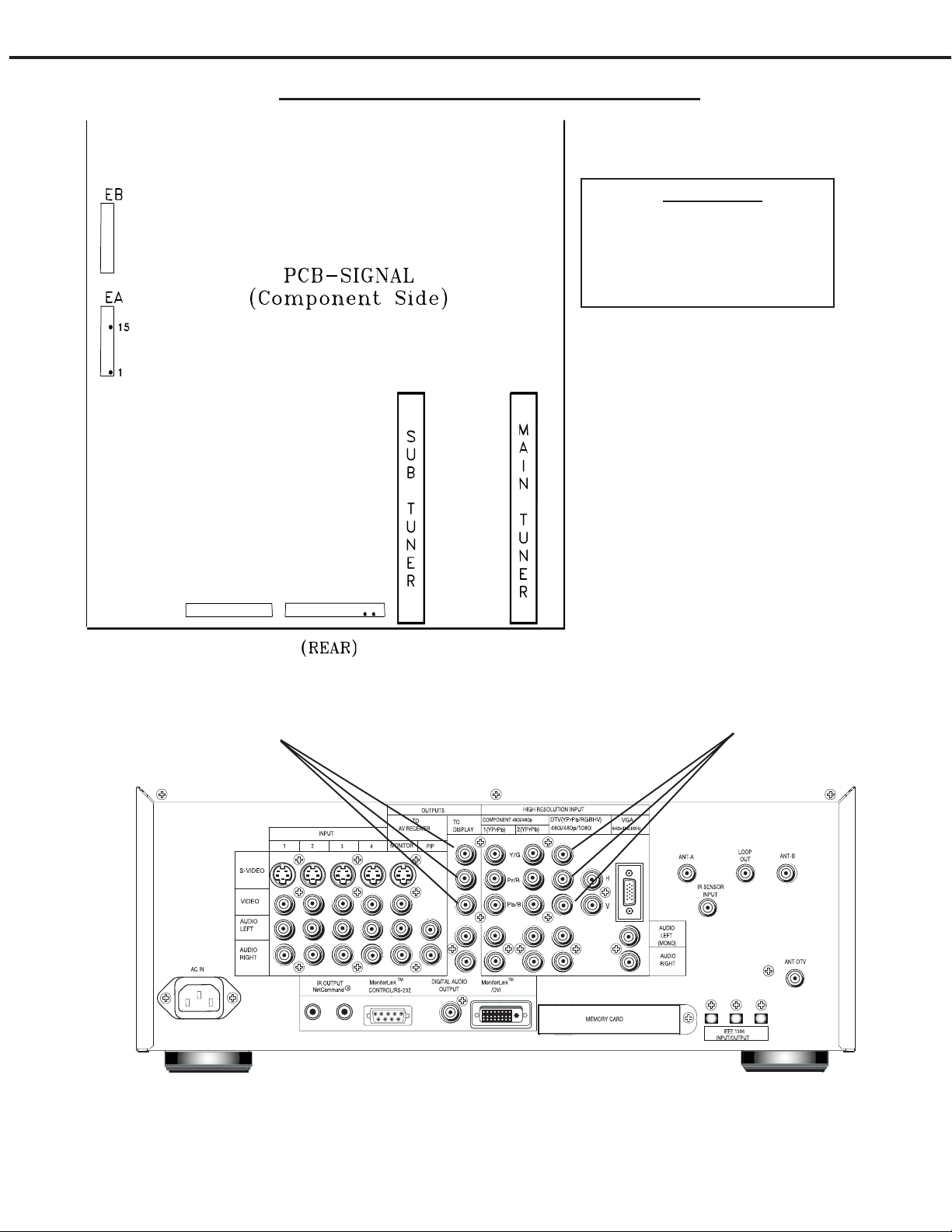
Adjustment Test Point Location
Test Points
EA pin 1 - Sub Picture (Y)
EA pin 15 - Main Picture (Y)
SUpin 4 - Left Audio
SU pin 6 - Right Audio
ST
OUTPUT
Y/Pr/Pb
SU
4
6
INTPUT
Y/Pr/Pb
Page 17
Page 17

[Audio Circuit]
MODELS: HD-5000 / HD-5000A
Purpose:
Check the input signal level to the MCS circuit
1. MCS Input Level
Measuring
Instrument
Test Point
Ext. Trigger
Measuring
Range
Input Signal
Input Terminal
Oscilloscope
Connector SU pins 6&4
------
50mV/Div
RF Stereo
300 Hz modulation
RF Input
ST
Symptom:
Distorted sound during a stereo broadcast.
1. Supply an RF MCS signal to the Ant A input, 300 Hz at 100% modulation
(25 kHz deviation) for right and left channels.
2. Connect the oscilloscope to connector SU pin 6 (Right Audio).
3. Enter the Adjustment Mode and select the Audio Function.
4. Verify that the Audio Function items are set to the dat a values given the
table below .
5. Set the data for Item “1 INP” for 1.28 Vp-p ±0.06V. (450mv ±10mv rms)
6. Connect the oscilloscope to connector ST pin 4 (Left Audio).
7. Confirm that the left audio level at pin 4 of the ST connector is 1.28 Vp-p
±0.06V (450mv ±20mv rms).
Note: Adjustment 2 (Stereo Separation) must be performed after this adjustment)
CIRCUIT ADJUST MODE
Layer …….. Cable/DBS/DTV
Activate …….. MENU-0-3-5-7
Function …...………..AUDIO
Item No. ……….…….VIDEO
Adjust Data ….…….ADJUST
Save Data …. ………ENTER
Exit …………..MENU (twice)
SU
4
6
AUDIO F un ctio n
Item # Abbrev. Data
1INP8
3WDE3
4SPC3
[Audio Circuit]
2. Separation
Measuring
Instrument
Test Point
Ext. Trigger
Measuring
Range
Input Signal
Input Terminal
Oscilloscope
Conector SU pin 6
------
10mV/Div
RF Stereo
RF Input
Purpose
Symptom:
Check stereo separation
Poor stereo separation
Note: This adjustment must follow Adjustment 1 (Input Level)
1. Supply a RF Stereo Signal (dual tone stereo) to the Ant. A input.
• Left Channel = 300 Hz modulation
• Right Channel = no modulation
2. Connect the oscilloscope to connector SU pin 6 (Right Audio).
3. Enter the Adjustment Mode and select the Audio Function.
4. Set the data for Item “3 WDE” for minimum 300 Hz signal.
5. Change the modulation frequency to 3kHz.
6. Adjust the data for Item “4 SPC” for minimum 3kHz signal.
CIRCUIT ADJUST MODE
Layer …….. Cable/DBS/DTV
Activate …….. MENU-0-3-5-7
Function …...………..AUDIO
Item No. ……….…….VIDEO
Adjust Data ….…….ADJUST
Save Data …. ………ENTER
Exit …………..MENU (twice)
ST
SU
4
6
Page 18
Page 18

[On Screen Display]
A
MODELS: HD-5000 / HD5000A
Purpose:
To position the character display horizontally.
3. Character Position
Measuring
Instrument
Test Point
Ext. Trigger
Measuring
Range
Input Signal
Input Terminal
Video Signal (NTSC/HD)
ANT-A / DTV INPUT
Symptom:
Incorrect display position
1. Supply a 480i signal to Ant-A and select Ant-A as the source.
2. Enter the ‘ADJUST GFX PLANE’ mode, press “MENU-0-3-9-9”.
3. Adjust “OSDSD” to center the OSD horizontally/vertically.
4. Press “MENU” to save data and exit the mode.
5. Supply an 1080i signal to DTV INPUT and select DTV INPUT as the source.
6. Adjust “OSDHD” to center the OSD horizontally/vertically.
7. Press “MENU” to save data and exit the mode.
CIRCUIT ADJUS T M O DE
Layer …….. Cable/DBS/DTV
ctivate …….. MENU-0-3-9-9
Adjust Data ….…….ADJUST
Save Data …. ………ENTER
Exit ………….. MENU (twice)
[Video Circuit]
4. Main/Sub Y Level
Measuring
Instrument
Test Point
Ext. Trigger
Measuring
Range
Input Signal
Input Terminal
Oscilloscope
EA connector pins 15 & 1
------
-----Color Bars
Video Input
Purpose
Symptom:
To set picture luminance
Excess or insufficient brightness.
1. Supply a color bar signal to a Video Input (not an RF input).
2. Select the color bar signal for both the main and sub pictures.
3. Connect the oscilloscope to connector EA pin 15.
4. Activate the Adjustment Mode
5. Select Item “3 YDRM” in the MNTS function.
6. Adjust the data for 0.7 Vp-p max. - 0.67 Vp-p min. at EA pin 15.
(If it cannot be adjusted within this range, set to the lower value)
7. Move the oscilloscope to EA pin 1.
8. Select Item “3 YDRS” in the SNTS function.
9. Adjust the data to equal the MAIN-Y Gain (+0.01V -0.04V).
CIRCUIT ADJUST MODE
Layer …….. Cable/DBS/DTV
Activate …….. MENU-0-3-5-7
Function …...………..AUDIO
Item No. ……….…….VIDEO
Adjust Data ….…….ADJUST
Save Data …. ………ENTER
Exit …………..MENU (twice)
ST
SU
4
6
Page 19
Page 19

[Gain & Offset Alignment]
5. 480P / 1080i Color Alignment
MODELS: HD-5000 / HD-5000A
Purpose:
Symptom:
T o set picture chroma on 480P and 1080i
Output color does not match input color
Measuring
Instrument
Test Point
Ext. Trigger
Measuring
Range
Input Signal
Input Terminal
Oscilloscope
Y/Pb/Pr OUTPUTS
-----10 (usec/div)
200 (mV/div) / 10 (mV/div)
Color Bar / Black Raster
480P & 1080i
(1) Connect an oscilloscope to Y/Pb/Pr of OUTPUTS TO DISPLAY on the back
panel. (terminated at 75Ω) .
(2) Input a full color bar signal (with 100% white level) of 480p (Y/Pb/Pr) to DTV-
INPUT.
(3) Go to the alignment mode (MENU+ 0 3 5 7).
(4) Select Video ADC by using ‘Audio’ button on remote.
(5) Adjust VideoADC item 10 GGAI so that the Y p-p is is equal to the source Y p-p
level (+/- 0.03V).
(6) Adjust VideoADC item 11 BGAI so that the Pb p-p is equal to the source Pb p-p
level (+/- 0.03V).
(7) Adjust VideoADC item 9 RGAI so that the Pr p-p is equal to the source Pr p-p
level (+/- 0.03V).
(8) Input a black raster signal of 480p (Y/Pb/Pr) to
DTV-INPUT.
(9) Adjust VideoADC item 13 GOFS so that the Y
offset level is 0.00Vp-p+/-0.01V.
(10) Adjust VideoADC item 14 BOFS so that the Pb
offset level is 0.00Vp-p+/-0.01V.
(11) Adjust VideoADC item 12 ROFS so that the Pr
offset level is 0.00Vp-p+/-0.01V.
(12) Switch input signal to 1080i and restart at #2.
Y/Pb/Pr
Adjustment Area
Y p-p
Offset Level
Pr p-p
Pb p-p
Page 20
Page 20

MODELS: HD-5000 / HD-5000A
CHIP PARTS REPLACEMENT
Some resistors, shorting jumpers (0 Ohm resistors),
ceramic capacitors, transistors and diodes are chip parts.
The following precautions should be taken when replacing
these parts.
Cautions:
1. Use a fine tipped, well insulated soldering iron
(approximately 30 watts), and tweezers.
2. Melt the solder and remove the chip parts
carefully so as not to tear the copper foil from
the printed circuit board.
3. Discard removed chips; do not reuse them.
4. Do not apply heat for more than 3 (three)
seconds to new chip parts.
5. Avoid using a rubbing stroke when soldering.
6. Take care not to scratch, or damage the chip
parts when soldering.
7. Supplementary cementing is not required.
Chip Parts Removal (Resistors, Capacitors, etc.)
1. Grasp the part with tweezers. Melt the solder
at both sides alternately , and remove one side
of the part with a twisting motion.
2. Melt the solder at the other side and remove
the part.
Chip Parts Removal (T ransistors)
1. Melt the solder of one lead and lift the side of
that lead upward.
2. Simultaneously melt the solder of the other
two leads and lift the part from the PCB.
Replacement
1. Presolder the contact points on the circuit
pattern.
2. Press the part downward with tweezers and
apply the soldering iron as shown.
PAGE 21
Page 21

MODELS: HD-5000 / HD-5000A
REPLACEMENT PARTS
Parts Ordering
T o expedite delivery of replacement parts orders, specify the following:
1. Model Number/Serial Number
2. Part Number and description
3. Quantity
Note: Unless complete information is supplied, delay in processing of orders will result.
Critical and Warranty Parts Designation
Critical Electrical Components are indicated by Bold Type in the Parts List, and in the schematic
diagrams by shading.
Warranty Return Parts are indicated in the Parts List with an (*).
Parts Tolerance Codes
Refer to the following chart for tolerance characteristics of electrical components.
MARK B C D F G J K
Tolerance % ± 0.1 ± 0.25 ± 0.5 ± 1 ± 2 ± 5 ± 10
MARK M N V X Z P Q
Tolerance %
MARK M N V X Z
Tolerance (pF) ± 0.1 ± 0.25 ± 0.5 ± 1 ± 2
± 20 ± 30 ± 10 + 40 + 80 + 100 + 30
-20 -20 - 0 -10
PAGE 22
Page 22

MODELS: HD-5000 / HD-5000A
[#] Model Legend:
(a) HD-5000, (b) HD-5000A
Ref # Part # Part Name & Description [#]
Ref # Part # Part Name & Description [#]
INTEGRATED CIRCUITS
IC201 263P384010 IC-C-MOS - TC74HC221AF-EL a
IC202 263P384010 IC-C-MOS - TC74HC221AF-EL
IC2A00 270P870010 IC - CXA2151Q
IC2A60 272P938010 IC - M52055FP
IC2B00 270P870010 IC - CXA2151Q
IC2C00 275P496010 IC-C-MOS - UPD64082GF-3BA
IC2C01 275P531010 IC-C-MOS - MSM54V16258B
IC2D01 272P379020 IC - LM1881MX (NSC)
IC2E00 270P658030 IC - CXA2019AQ/T4
IC2F50 272P379020 IC - LM1881MX (NSC)
IC2F60 272P379020 IC - LM1881MX (NSC)
IC2F70 275P718010 IC-C-MOS - TC74HC4053FT
IC2F80 275P718010 IC-C-MOS - TC74HC4053FT
IC2H00 270P658030 IC - CXA2019AQ/T4
IC2K00 270P623010 IC - CXA2069Q
IC2L00 270P623010 IC - CXA2069Q
IC2R00 275P269010 IC-C-MOS - ADM331EARS
IC2V00 270P663020 IC - CXA2101AQ
IC2V01 270P664010 IC - CXA2102Q
IC2V02 263P384010 IC-C-MOS - TC74HC221AF-EL
IC2V03 270P870010 IC - CXA2151Q
IC2V90 275P419010 IC-C-MOS - SN74AHCT1G126DBV
IC2Y01 270P526020 IC - MM11 1 1XF
IC301 270P938010 IC - MC33202D
IC3A01 270P467010 IC - TDA9855
IC5100 275P686010 IC-C-MOS - TSB41AB3PFP
IC5101 275P624010 IC-C-MOS - TSB42AA4
IC5102 274P670010 IC - 24LC04BT*SN
IC5103 275P679010 IC-C-MOS - TC74LCX74FT
IC5251 270P988010 IC-OP AMP - LM358M
IC5252 270P877010 IC - UPC3217GV
IC5253 270P877010 IC - UPC3217GV
IC5290 270P677030 IC - BAO9FP
IC52A0 275P715020 IC-C-MOS - BCM3510KPF P22
IC52A1 275P662020 IC-C-MOS - CY7C1019CV33-15
IC52A2 270P806030 IC - SI-3018LSA
IC5300 275P957010 IC-C-MOS - TL811A3
IC5301 275P672010 IC-C-MOS - RM5231-200Q
IC5302 275P675010 IC-C-MOS - SN74LV125APWR
IC5303 275P666010 IC-C-MOS - MAX6358SYUT-T
IC53A0 275P888010 IC-C-MOS - MT48LC16M16A2TG
IC53A1 275P888010 IC-C-MOS - MT48LC16M16A2TG
IC53A2 275P888010 IC-C-MOS - MT48LC16M16A2TG
IC53A3 275P888010 IC-C-MOS - MT48LC16M16A2TG
IC53J3 275P970010 IC-C-MOS - SIL170BCL64
IC53J4 270P998010 IC-C-MOS - LM317EMP
IC53J6 275P894010 IC-C-MOS - AD9883AKST-110
IC53J7 275P778010 IC-C-MOS - AD7196AKS
IC53J8 270P997010 IC-C-MOS - SM5301AS
IC53J9 275P464010 IC-C-MOS - TC7WH14FK
IC53K0 271P004010 IC - CM1208-08MS
IC5400 275P677010 IC-C-MOS - SN74LVC573APWR
IC5403 275P864010 IC-C-MOS - MD2211-D16-V3
IC5407 275P124040 IC-C-MOS - SN74LVC245APWR
IC5408 275P665010 IC-C-MOS - M66230FP
IC5409 275P379020 IC-C-MOS - SN74LVC00APW
IC5410 275P122020 IC-C-MOS - SN74LV32APWR
IC541 1 275P674010 IC-C-MOS - SN74LV123APWR
IC5412 275P664010 IC-C-MOS - IDTQS34XVH245Q3
IC54A0 275P726010 IC-C-MOS - PIC17C43T-25/L
IC54K1 275P673010 IC-C-MOS - RTC-8563SA
IC54K5 275P270010 IC-C-MOS - M66010GP
IC54Z1 275P657050 IC-C-MOS - 24LC256T-I/SN
IC54Z3 275P657050 IC-C-MOS - 24LC256T-I/SN
IC54Z4 270P880010 IC - 24LC64I/SN
IC55A0 275P685040 IC-C-MOS - TL850D
IC55A2 275P669010 IC-C-MOS - MK2771-15
IC55A3 275P689010 IC-C-MOS - ICS551MT
IC55A4 275P689010 IC-C-MOS - ICS551MT
IC55A6 275P741020 IC-C-MOS - MT48LC8M16A2TG
IC55A7 275P741020 IC-C-MOS - MT48LC8M16A2TG
IC55A8 275P741020 IC-C-MOS - MT48LC8M16A2TG
IC55A9 275P741020 IC-C-MOS - MT48LC8M16A2TG
IC55C2 275P668010 IC-C-MOS - MK2716STR
IC55C3 275P680010 IC-C-MOS - TC74VCX257FT
IC55C4 275P680010 IC-C-MOS - TC74VCX257FT
IC55E0 279P069030 IC - SN74LVTH244APW
IC55E1 275P464010 IC-C-MOS - TC7WH14FK
IC55E2 275P388010 IC-C-MOS - ICS1523M
IC55E3 275P679010 IC-C-MOS - TC74LCX74FT
IC55F0 267P158010 HIC - AF-9317B
IC5600 275P379020 IC-C-MOS - SN74LVC00APW
IC5601 275P659010 IC-C-MOS - CS8414-CSR
IC5602 279P069030 IC - SN74LVTH244APW
IC5603 275P661040 IC-C-MOS - CS493002-CLR
IC5604 275P678010 IC-C-MOS - SN74LVTH16374DGG
IC5605 274D104020 IC-C-MOS - A T_49LV001_12TC
IC5606 275P464010 IC-C-MOS - TC7WH14FK
IC5607 275P660020 IC-C-MOS - CS4341-KSR
IC5670 270P938010 IC - MC33202D
IC56A0 275P169030 IC-C-MOS - M65677FP
IC56C0 276P019090 IC-C-MOS - M4A3-128/64-55VC
IC5900 270P953010 IC - MIC39300-2.5BU
IC59P0 270P879010 IC - SC1566IM-2.5
IC7A00 276P017010 IC-C-MOS - M306V7FGFP
IC7A01 275P533010 IC-C-MOS - M24C64WM6T
IC7A02 270P706020 IC - MAX823REUK
IC7A03 271P023010 IC - SN74CBTD1G125DBVR
IC7A04 271P023010 IC - SN74CBTD1G125DBVR
IC7A05 271P023010 IC - SN74CBTD1G125DBVR
IC7A06 271P023010 IC - SN74CBTD1G125DBVR
IC7A08 271P023010 IC - SN74CBTD1G125DBVR
IC7A09 271P023010 IC - SN74CBTD1G125DBVR
IC7A10 271P023010 IC - SN74CBTD1G125DBVR
IC7A11 271P023010 IC - SN74CBTD1G125DBVR
IC7D00 275P451010 IC-C-MOS - TC74HC4066AFN
IC7D01 275P560010 IC-C-MOS - ADS931E
IC7D02 275P560010 IC-C-MOS - ADS931E
IC7D03 275P560010 IC-C-MOS - ADS931E
IC7D10 275P535010 IC-C-MOS - TC74AC157FN-ELP
IC7D11 275P535010 IC-C-MOS - TC74AC157FN-ELP
IC7E00 275P451010 IC-C-MOS - TC74HC4066AFN
IC7E01 275P560010 IC-C-MOS - ADS931E
IC7E02 275P560010 IC-C-MOS - ADS931E
IC7E03 275P560010 IC-C-MOS - ADS931E
IC7E10 275P535010 IC-C-MOS - TC74AC157FN-ELP
IC7E11 275P535010 IC-C-MOS - TC74AC157FN-ELP
PAGE 23
Page 23

MODELS: HD-5000 / HD-5000A
[#] Model Legend:
(a) HD-5000, (b) HD-5000A
Ref # Part # Part Name & Description [#]
Ref # Part # Part Name & Description [#]
IC7G01 275P247010 IC-C-MOS - MB40C958VPFV
IC7G04 275P534010 IC-C-MOS - TC74HCT574AFW-ELP a
IC7G04 275P681010 IC-C-MOS - TC74HCT574AFW b
IC7G05 275P534010 IC-C-MOS - TC74HCT574AFW-ELP a
IC7G05 275P681010 IC-C-MOS - TC74HCT574AFW b
IC7H00 275P714010 IC-C-MOS - NT56V1616A0T-7
IC7H01 275P714010 IC-C-MOS - NT56V1616A0T-7
IC7H02 275P436030 IC-C-MOS - TMC57127PPM
IC7H03 275P439030 IC-C-MOS - MSM534031E
IC7H04 270P506010 IC - M51957BFP
IC7H05 263P384010 IC-C-MOS - TC74HC221AF-EL
IC7H06 270P348010 IC - TLC2932IPW
IC7H07 275P437020 IC - SLA4028
IC7H08 270P348010 IC - TLC2932IPW
IC7H09 274P901010 IC-C-MOS - TC74HCT7007AF
IC7H11 275P535010 IC-C-MOS - TC74AC157FN-ELP a
IC7H11 275P769010 IC-C-MOS - TC74AC157FT b
IC7H12 275P535010 IC-C-MOS - TC74AC157FN-ELP a
IC7H12 275P769010 IC-C-MOS - TC74AC157FT b
IC7H13 275P535010 IC-C-MOS - TC74AC157FN-ELP a
IC7H13 275P769010 IC-C-MOS - TC74AC157FT b
IC7H14 275P535010 IC-C-MOS - TC74AC157FN-ELP a
IC7H14 275P769010 IC-C-MOS - TC74AC157FT b
IC7R1 270P575020 IC - NJM78M05DLA - TEI
IC8000 275P980010 IC-C-MOS - SAA7115HL
IC8001 270P817010 IC - L4931CDT33-TR
IC801 271P009010 IC - RT9172-25CG b
IC802 270P817010 IC - L4931CDT33-TR b
IC803 275P464010 IC-C-MOS - TC7WH14FK b
IC8D04 275P997010 IC-C-MOS - IP00C720 b
IC8D05 275P982010 IC - MT48LC2M32B2-7 b
IC9A20 267P159010 HIC - STR-G6623
IC9A21 270P816010 IC - NJM431L
IC9A22 267P076030 HIC - SI-3050C
IC9B00 270P872010 IC - HIP6006CB
IC9C00 270P677020 IC - BA05FP
IC9C01 270P677030 IC - BAO9FP
IC9C02 270P677030 IC - BAO9FP
IC9C03 270P950010 IC - NJM78M09DL1A(TE1)
IC9C04 270P817010 IC - L4931CDT33-TR
IC9C05 270P677030 IC - BAO9FP
IC9C20 270P677010 IC - BA033FP
IC9C40 270P696010 IC - BA05SFP
IC9C50 270P817010 IC - L4931CDT33-TR
TRANSISTORS
CHIP Type Transistors (Listed by Part No.)
Part No. Description
260P806010 DTA124EK/UN2112
260P807030 DTC124EKAT146
260P817010 2SA1037K-Q
260P817020 2SA1037K-R
260P817050 2SA1037K-R,S/2SB709AI-R,S
260P817080 2SA1037K-R,S
260P818010 2SC2412K-Q
260P818050 2SC2412K-R,S/2SD601AI-R,S
260P818080 2SC2412K-R,S
260P835030 2SC2413K-Q
260P836090 2SC3326-A,B
260P846030 DTC143ZKAT146
261P067030 DTC124EKA/RT1N241C
TRANSISTORS
Conventional Transistors (By Ref #)
Ref # Part # Part Name & Description
Q5250 261P026010 TR - 2SC3356
Q54A2 261P114010 TR - 2SA1585STPR
Q901 260P691010 TR - 2SA1358-Y
Q902 260C004010 TR - 2SC1740S-R,S/2SC3311A-R,S
Q9A20 261P101010 TR - PHP21N06T
Q9A21 260C004010 TR - 2SC1740S-R,S/2SC3311A-R,S
Q9A22 260C004010 TR - 2SC1740S-R,S/2SC3311A-R,S
Q9A54 260C004010 TR - 2SC1740S-R,S/2SC3311A-R,S
Q9B00 261P136010 TR - FDS6680A
Q9B01 261P136010 TR - FDS6680A
Q9B02 261P133010 TR - FDS6612A
DIODES
D2M22 264P822010 D-CHIP - HSM2838
D5280 262P089010 DIODE - MA2S728
D52A0 262P071070 DIODE-LE - SML-210FT
D5300 262P802010 D-CHIP - 1SS302
D5301 262P802010 D-CHIP - 1SS302
D53J0 264P846010 DIODE-CHIP - MA732
D53J9 262P802010 D-CHIP - 1SS302
D53K0 262P802010 D-CHIP - 1SS302
D5401 262P071070 DIODE-LE - SML-210FT
D54K0 264P808010 DIODE-CHIP - DAN202K
D55A0 262P078010 DIODE - LM385M3-1.2
D7H01 264P828010 D-CHIP - DAN202U/MA142WK
D7K21 262P099010 DIODE-LE-CHIP - SML011BBT
D7K22 262P099010 DIODE-LE-CHIP - SML011BBT
D7K23 262P099010 DIODE-LE-CHIP - SML011BBT
D7K24 262P099010 DIODE-LE-CHIP - SML011BBT
D7K25 262P099010 DIODE-LE-CHIP - SML011BBT
D7K26 262P099010 DIODE-LE-CHIP - SML011BBT
D7K27 262P099010 DIODE-LE-CHIP - SML011BBT
D7K28 262P099010 DIODE-LE-CHIP - SML011BBT
D7K29 262P099010 DIODE-LE-CHIP - SML011BBT
D9A01 262P031010 DIODE - D6SB80
D9A21 264P899010 DIODE - BYV26E
D9A22 264P045080 DIODE - 1S2076A/1S2471OM
D9A23 264P045080 DIODE - 1S2076A/1S2471OM
D9A24 264P045080 DIODE - 1S2076A/1S2471OM
D9A25 264P045080 DIODE - 1S2076A/1S2471OM
D9A28 264P045080 DIODE - 1S2076A/1S2471OM
D9A29 264P460060 DIODE - EQA02-05C/RD5.1EB1
D9A30 262P066010 DIODE - RU4A
D9A31 264P045080 DIODE - 1S2076A/1S2471OM
D9A32 264P045080 DIODE - 1S2076A/1S2471OM
D9A33 264P628010 DIODE - FMB-G14L
D9A34 264P470080 DIODE - EQA02-32C/RD33EB4
D9A35 264P469090 DIODE - EQA02-28C/RD30EB2
D9B00 264P669030 DIODE - S3L20U
D9B01 264P718010 DIODE - FR155
D9B02 264P669030 DIODE - S3L20U
D9B04 264P458050 DIODE - RD3.9EB1
D9B05 264P461050 DIODE - EQA02-06B/RD5.6EB3
PAGE 24
Page 24

MODELS: HD-5000 / HD-5000A
[#] Model Legend:
(a) HD-5000, (b) HD-5000A
Ref # Part # Part Name & Description [#]
Ref # Part # Part Name & Description [#]
COILS
L1A06 409P923060 EMI-F-CHIP - BLM21B272S
L1A07 409P923060 EMI-F-CHIP - BLM21B272S
L1A09 325C146030 COIL-CHIP - 10MH-J
L1A13 409P923060 EMI-F-CHIP - BLM21B272S
L1A50 325C146030 COIL-CHIP - 10MH-J
L1A51 321C114010 COIL-RF - 2200MH-J
L1B06 409P923060 EMI-F-CHIP - BLM21B272S
L1B07 409P923060 EMI-F-CHIP - BLM21B272S
L1B09 325C146030 COIL-CHIP - 10MH-J
L1B13 409P923060 EMI-F-CHIP - BLM21B272S
L1B50 325C146030 COIL-CHIP - 10MH-J
L1B51 321C114010 COIL-RF - 2200MH-J
L2991 409P876040 EMI-F-CHIP - CNF20C221S/CKD510JB1H221S
L2992 409P876040 EMI-F-CHIP - CNF20C221S/CKD510JB1H221S
L2993 409P876040 EMI-F-CHIP - CNF20C221S/CKD510JB1H221S
L2995 409P876040 EMI-F-CHIP - CNF20C221S/CKD510JB1H221S
L2A00 325C241030 COIL-CHIP - 10MH-K
L2A60 325C241030 COIL-CHIP - 10MH-K
L2B00 325C241030 COIL-CHIP - 10MH-K
L2C01 325C146050 COIL-CHIP - 15MH-J
L2C03 409P777080 EMI-F-CHIP - BLM21P221S
L2C05 409P777080 EMI-F-CHIP - BLM21P221S
L2C06 409P777080 EMI-F-CHIP - BLM21P221S
L2D01 325C146030 COIL-CHIP - 10MH-J
L2D03 325C146030 COIL-CHIP - 10MH-J
L2D08 409P777080 EMI-F-CHIP - BLM21P221S
L2D20 325C146030 COIL-CHIP - 10MH-J
L2E03 409P777080 EMI-F-CHIP - BLM21P221S
L2E25 409P777080 EMI-F-CHIP - BLM21P221S
L2F50 409P923060 EMI-F-CHIP - BLM21B272S
L2F60 409P777080 EMI-F-CHIP - BLM21P221S
L2F70 409P923060 EMI-F-CHIP - BLM21B272S
L2F80 409P923060 EMI-F-CHIP - BLM21B272S
L2H60 325C146030 COIL-CHIP - 10MH-J
L2H61 325C146030 COIL-CHIP - 10MH-J
L2K42 409P777080 EMI-F-CHIP - BLM21P221S
L2L42 409P777080 EMI-F-CHIP - BLM21P221S
L2M00 409P777080 EMI-F-CHIP - BLM21P221S
L2M20 409P777080 EMI-F-CHIP - BLM21P221S
L2R00 325C461090 COIL-PEAKING - 33MH-K
L2V01 409P923060 EMI-F-CHIP - BLM21B272S
L2V02 409P923060 EMI-F-CHIP - BLM21B272S
L2V03 325C241050 COIL-CHIP - 15MH-K
L2V06 325C242010 COIL-CHIP - 47MH-K
L2V10 325C241050 COIL-CHIP - 15MH-K
L2V72 325C242010 COIL-CHIP - 47MH-K
L2V95 409P923060 EMI-F-CHIP - BLM21B272S
L2W01 325C242010 COIL-CHIP - 47MH-K
L2X01 409P923060 EMI-F-CHIP - BLM21B272S
L2X30 409P923060 EMI-F-CHIP - BLM21B272S
L2Y10 409P923060 EMI-F-CHIP - BLM21B272S
L2Y30 409P923060 EMI-F-CHIP - BLM21B272S
L301 325C241030 COIL-CHIP - 10MH-K
L3A37 409P923060 EMI-F-CHIP - BLM21B272S
L5105 351P216010 COIL-CH-CHIP - 857CM-0009
L51 1 5 351P216010 COIL-CH-CHIP - 857CM-0009
L5125 351P216010 COIL-CH-CHIP - 857CM-0009
L51P2 409P865020 EMI-F-CHIP - BLM11A601S
L51P3 409P777080 EMI-F-CHIP - BLM21P221S
L51P4 409P777080 EMI-F-CHIP - BLM21P221S
L5205 409P936030 EMI-F-CHIP - BK1608 HS470
L5205 409P956020 EMI-F-CHIP - BLM18AG221S a
L5206 409P936030 EMI-F-CHIP - BK1608 HS470
L5206 409P956020 EMI-F-CHIP - BLM18AG221S a
L5207 409P936030 EMI-F-CHIP - BK1608 HS470
L5207 409P956020 EMI-F-CHIP - BLM18AG221S a
L5208 409P936030 EMI-F-CHIP - BK1608 HS470
L5208 409P956020 EMI-F-CHIP - BLM18AG221S a
L5230 325C240050 COIL-CHIP - 2.2MH-M
L5233 325C342050 COIL-CHIP - 100MH-K
L5250 325C140050 COIL-CHIP - 2.2MH-M/K/J
L5250 325C144090 COIL-CHIP - 0.68MH-M -OR-K
L5251 325C140050 COIL-CHIP - 2.2MH-M/K/J
L5252 325C140050 COIL-CHIP - 2.2MH-M/K/J
L5253 325C140010 COIL-CHIP - 1MH-M
L5253 325C140040 COIL-CHIP - 1.8MH-M -OR-K-OR-J
L5254 325C140010 COIL-CHIP - 1MH-M
L5256 409P956010 EMI-F-CHIP - BLM18PG121S
L5290 325C140050 COIL-CHIP - 2.2MH-M/K/J
L5291 325C340050 COIL-CHIP - 2.2MH-M
L5292 325C140050 COIL-CHIP - 2.2MH-M/K/J
L52A0 409P777080 EMI-F-CHIP - BLM21P221S
L52A1 409P777080 EMI-F-CHIP - BLM21P221S
L52A2 409P956010 EMI-F-CHIP - BLM18PG121S
L52A3 409P956010 EMI-F-CHIP - BLM18PG121S
L5300 325C341070 COIL-CHIP - 22MH-K
L5301 409P777080 EMI-F-CHIP - BLM21P221S
L5302 409P777080 EMI-F-CHIP - BLM21P221S
L5303 409P777080 EMI-F-CHIP - BLM21P221S
L53J1 409P865090 EMI-F-CHIP - BLM1 1A121S
L53J2 409P865090 EMI-F-CHIP - BLM1 1A121S
L53J3 409P865090 EMI-F-CHIP - BLM1 1A121S
L53J4 409P865090 EMI-F-CHIP - BLM1 1A121S
L53J5 409P865090 EMI-F-CHIP - BLM1 1A121S
L53J6 409P865090 EMI-F-CHIP - BLM1 1A121S
L53J7 409P865090 EMI-F-CHIP - BLM1 1A121S
L53J8 409P865090 EMI-F-CHIP - BLM1 1A121S
L53J9 409P865090 EMI-F-CHIP - BLM1 1A121S
L5400 409P876020 EMI-F-CHIP - CNF20C470S/CKD510JB1H470S
L5401 409P876020 EMI-F-CHIP - CNF20C470S/CKD510JB1H470S
L5402 409P876020 EMI-F-CHIP - CNF20C470S/CKD510JB1H470S
L5403 409P876020 EMI-F-CHIP - CNF20C470S/CKD510JB1H470S
L54D0 409P876020 EMI-F-CHIP - CNF20C470S/CKD510JB1H470S
L54D1 409P876020 EMI-F-CHIP - CNF20C470S/CKD510JB1H470S
L54D2 409P876020 EMI-F-CHIP - CNF20C470S/CKD510JB1H470S
L54D3 409P876020 EMI-F-CHIP - CNF20C470S/CKD510JB1H470S
L55A0 409P777080 EMI-F-CHIP - BLM21P221S
L55A1 409P777080 EMI-F-CHIP - BLM21P221S
L55A2 409P777080 EMI-F-CHIP - BLM21P221S
L55A3 409P777080 EMI-F-CHIP - BLM21P221S
L55A4 409P777080 EMI-F-CHIP - BLM21P221S
L55C0 409P777080 EMI-F-CHIP - BLM21P221S
L55E0 409P944010 EMI-F-CHIP - NFL21SP107X1
L55E1 409P944010 EMI-F-CHIP - NFL21SP107X1
L55E2 409P944010 EMI-F-CHIP - NFL21SP107X1
L55E3 409P945010 EMI-F-CHIP - NFL21SP506X13CD
L55E4 409P945010 EMI-F-CHIP - NFL21SP506X13CD
L55E5 409P945010 EMI-F-CHIP - NFL21SP506X13CD
PAGE 25
Page 25

MODELS: HD-5000 / HD-5000A
[#] Model Legend:
(a) HD-5000, (b) HD-5000A
Ref # Part # Part Name & Description [#]
Ref # Part # Part Name & Description [#]
L55E6 409P945010 EMI-F-CHIP - NFL21SP506X13CD
L55E7 409P945010 EMI-F-CHIP - NFL21SP506X13CD
L55F0 409P945010 EMI-F-CHIP - NFL21SP506X13CD
L55F1 409P945010 EMI-F-CHIP - NFL21SP506X13CD
L55F2 409P945010 EMI-F-CHIP - NFL21SP506X13CD
L55F4 409P876020 EMI-F-CHIP - CNF20C470S/CKD510JB1H470S
L55F5 409P945010 EMI-F-CHIP - NFL21SP506X13CD
L55F6 409P945010 EMI-F-CHIP - NFL21SP506X13CD
L5602 325C141030 COIL-CHIP - 10MH-K
L5603 325C141030 COIL-CHIP - 10MH-K
L56C0 325C341030 COIL-CHIP - 10MH-K
L56D0 409P945010 EMI-F-CHIP - NFL21SP506X13CD
L56D1 409P945010 EMI-F-CHIP - NFL21SP506X13CD
L5900 409P809010 EMI-FILTER - BNX002-01
L5901 325C241050 COIL-CHIP - 15MH-K
L5905 325C241030 COIL-CHIP - 10MH-K
L5906 325C241050 COIL-CHIP - 15MH-K
L59A0 409P809010 EMI-FILTER - BNX002-01
L59A1 409P777080 EMI-F-CHIP - BLM21P221S
L59E0 411P012010 FERRITE-BEAD
L59K0 325C241050 COIL-CHIP - 15MH-K
L59K1 325C141030 COIL-CHIP - 10MH-K
L59L0 409P923060 EMI-F-CHIP - BLM21B272S
L59M0 325C140050 COIL-CHIP - 2.2MH-M/K/J
L59M1 325C141090 COIL-CHIP - 33MH-K
L59N0 325C141090 COIL-CHIP - 33MH-K
L59R0 325C341030 COIL-CHIP - 10MH-K
L59R3 325C341030 COIL-CHIP - 10MH-K
L7A01 325C146030 COIL-CHIP - 10MH-J
L7A02 409P923060 EMI-F-CHIP - BLM21B272S
L7A03 409P923060 EMI-F-CHIP - BLM21B272S
L7C20 409P923060 EMI-F-CHIP - BLM21B272S
L7C21 409P923060 EMI-F-CHIP - BLM21B272S
L7C22 409P777050 EMI-F-CHIP - BLM21B201S
L7C23 409P777050 EMI-F-CHIP - BLM21B201S
L7C24 409P777050 EMI-F-CHIP - BLM21B201S
L7D01 325C241030 COIL-CHIP - 10MH-K
L7D11 325C242010 COIL-CHIP - 47MH-K
L7D12 409P777020 EMI-F-CHIP - BLM21A05
L7D13 325C241030 COIL-CHIP - 10MH-K
L7D14 325C241030 COIL-CHIP - 10MH-K
L7D15 325C241030 COIL-CHIP - 10MH-K
L7E01 325C241030 COIL-CHIP - 10MH-K
L7E11 325C242010 COIL-CHIP - 47MH-K
L7E12 409P777020 EMI-F-CHIP - BLM21A05
L7E13 325C241030 COIL-CHIP - 10MH-K
L7E14 325C241030 COIL-CHIP - 10MH-K
L7E15 325C241030 COIL-CHIP - 10MH-K
L7G00 325C242050 COIL-CHIP - 100MH-K
L7G10 325C242050 COIL-CHIP - 100MH-K
L7G11 325C241030 COIL-CHIP - 10MH-K
L7G12 325C241030 COIL-CHIP - 10MH-K
L7H10 325C241030 COIL-CHIP - 10MH-K
L7H11 409P777080 EMI-F-CHIP - BLM21P221S
L7H12 325C241030 COIL-CHIP - 10MH-K
L7H13 325C241030 COIL-CHIP - 10MH-K
L7H14 325C241030 COIL-CHIP - 10MH-K
L7H15 325C241030 COIL-CHIP - 10MH-K
L7H16 325C241030 COIL-CHIP - 10MH-K
L7H17 325C241030 COIL-CHIP - 10MH-K
L7H19 409P777080 EMI-F-CHIP - BLM21P221S
L7H20 325C241030 COIL-CHIP - 10MH-K
L7H30 325C241030 COIL-CHIP - 10MH-K
L7H31 325C241030 COIL-CHIP - 10MH-K
L7H32 409P777080 EMI-F-CHIP - BLM21P221S
L7H38 325C241030 COIL-CHIP - 10MH-K
L7H40 325C241030 COIL-CHIP - 10MH-K
L7H41 409P777080 EMI-F-CHIP - BLM21P221S
L7H42 409P777080 EMI-F-CHIP - BLM21P221S
L7H50 409P777080 EMI-F-CHIP - BLM21P221S
L7H60 325C241030 COIL-CHIP - 10MH-K
L7H70 325C241030 COIL-CHIP - 10MH-K
L7H80 325C241030 COIL-CHIP - 10MH-K a
L7K01 325C242050 COIL-CHIP - 100MH-K
L8000 409P777080 EMI-F-CHIP - BLM21P221S
L8001 409P923060 EMI-F-CHIP - BLM21B272S
L8002 409P777080 EMI-F-CHIP - BLM21P221S
L801 409P777080 EMI-F-CHIP - BLM21P221S b
L802 409P777080 EMI-F-CHIP - BLM21P221S b
L803 325C241030 COIL-CHIP - 10MH-K b
L804 409P777080 EMI-F-CHIP - BLM21P221S b
L8D05 409P777080 EMI-F-CHIP - BLM21P221S b
L8D06 409P777080 EMI-F-CHIP - BLM21P221S b
L8D08 409P777080 EMI-F-CHIP - BLM21P221S b
L8D09 409P777080 EMI-F-CHIP - BLM21P221S b
L9A02 351P223010 FILTER-LINE - SLF15N0601
L9A20 411D009020 FERRITE-CORE - ZBF503D-01
L9A21 411D009020 FERRITE-CORE - ZBF503D-01
L9A22 321C141020 COIL-RF - 8.2MH
L9A23 321C141020 COIL-RF - 8.2MH
L9A24 321C141020 COIL-RF - 8.2MH
L9B01 321C140060 COIL-RF - 2.7MH-M
L9B02 321C141070 COIL-RF - 22MH-K
L9B03 321C140060 COIL-RF - 2.7MH-M
L9B04 321C140060 COIL-RF - 2.7MH-M
L9D00 351P222010 FILTER-LINE - ELF24V050A
L9D01 351P222010 FILTER-LINE - ELF24V050A
LC2J01 409P876060 EMI-F-CHIP - CNF20R102S/CKD510JB1H1025
LC2J02 409P876060 EMI-F-CHIP - CNF20R102S/CKD510JB1H1025
LC2J03 409P876060 EMI-F-CHIP - CNF20R102S/CKD510JB1H1025
LC2J04 409P876060 EMI-F-CHIP - CNF20R102S/CKD510JB1H1025
LC2J05 409P876060 EMI-F-CHIP - CNF20R102S/CKD510JB1H1025
LC7D02 409P875090 EMI-F-CHIP - ELKE103FA
LC7D05 409P875090 EMI-F-CHIP - ELKE103FA
LC7D10 409P876020 EMI-F-CHIP - CNF20C470S/CKD510JB1H470S
LC7D11 409P876020 EMI-F-CHIP - CNF20C470S/CKD510JB1H470S
LC7D12 409P876020 EMI-F-CHIP - CNF20C470S/CKD510JB1H470S
LC7D13 409P876020 EMI-F-CHIP - CNF20C470S/CKD510JB1H470S
LC7D14 409P876020 EMI-F-CHIP - CNF20C470S/CKD510JB1H470S
LC7E10 409P876020 EMI-F-CHIP - CNF20C470S/CKD510JB1H470S
LC7E1 1 409P876020 EMI-F-CHIP - CNF20C470S/CKD510JB1H470S
LC7E12 409P876020 EMI-F-CHIP - CNF20C470S/CKD510JB1H470S
LC7E13 409P876020 EMI-F-CHIP - CNF20C470S/CKD510JB1H470S
LC7E14 409P876020 EMI-F-CHIP - CNF20C470S/CKD510JB1H470S
LC7G01 409P876020 EMI-F-CHIP - CNF20C470S/CKD510JB1H470S
LC7G02 409P876020 EMI-F-CHIP - CNF20C470S/CKD510JB1H470S
LC7G03 409P876020 EMI-F-CHIP - CNF20C470S/CKD510JB1H470S
LC7G04 409P876020 EMI-F-CHIP - CNF20C470S/CKD510JB1H470S
LC7G05 409P876020 EMI-F-CHIP - CNF20C470S/CKD510JB1H470S
LC7G06 409P876020 EMI-F-CHIP - CNF20C470S/CKD510JB1H470Sa
PAGE 26
Page 26

MODELS: HD-5000 / HD-5000A
[#] Model Legend:
(a) HD-5000, (b) HD-5000A
Ref # Part # Part Name & Description [#]
Ref # Part # Part Name & Description [#]
LC7G07 409P876020 EMI-F-CHIP - CNF20C470S/CKD510JB1H470Sa
LC7G08 409P875090 EMI-F-CHIP - ELKE103FA
LC7G09 409P875090 EMI-F-CHIP - ELKE103FA
LC7G10 409P876020 EMI-F-CHIP - CNF20C470S/CKD510JB1H470S
LC7G1 1 409P876020 EMI-F-CHIP - CNF20C470S/CKD510JB1H470S
LC7G12 409P876020 EMI-F-CHIP - CNF20C470S/CKD510JB1H470S
LC7G13 409P876020 EMI-F-CHIP - CNF20C470S/CKD510JB1H470Sa
LC7G14 409P876020 EMI-F-CHIP - CNF20C470S/CKD510JB1H470S
LC7G15 409P876020 EMI-F-CHIP - CNF20C470S/CKD510JB1H470S
LC7J03 409P876020 EMI-F-CHIP - CNF20C470S/CKD510JB1H470Sa
LC7J04 409P876020 EMI-F-CHIP - CNF20C470S/CKD510JB1H470S
LC7J05 409P876020 EMI-F-CHIP - CNF20C470S/CKD510JB1H470S
LC7J10 409P876020 EMI-F-CHIP - CNF20C470S/CKD510JB1H470S
LC7J13 409P876020 EMI-F-CHIP - CNF20C470S/CKD510JB1H470Sa
LC7J14 409P876020 EMI-F-CHIP - CNF20C470S/CKD510JB1H470Sa
LC7J15 409P876020 EMI-F-CHIP - CNF20C470S/CKD510JB1H470Sa
LF56A1 409P900010 FILTER-LP - 7MHZ SMD
LF7D00 409P901010 LP-FILTER - 14MHZ SMD
LF7D01 409P901010 LP-FILTER - 14MHZ SMD
LF7D02 409P901010 LP-FILTER - 14MHZ SMD
LF7E00 409P901010 LP-FILTER - 14MHZ SMD
LF7E01 409P901010 LP-FILTER - 14MHZ SMD
LF7E02 409P901010 LP-FILTER - 14MHZ SMD
LF7G00 409P901010 LP-FILTER - 14MHZ SMD
LF7G01 409P901010 LP-FILTER - 14MHZ SMD
LF7G02 409P901010 LP-FILTER - 14MHZ SMD
TRANSFORMERS
T9A20 350P766020 TRANS-PWR - ETS35AASJ3ND
T9B00 350P788010 TRANS-PWR - TCGSB 60262R7M1
RESISTORS
CHIP Type Resistors (Listed by Value)
Part No. Value Part No. Value
103P489050 1/4W 00HM 103P810050 1/16W 150-D
103P409050 1/8W 0OHM 103P490050 1/16W 150-F
103P509050 1/16W 0OHM 103P501050 1/16W 150-J
103P509000 1/16W 6.8-J 103P490060 1/16W 160-F
103P400010 1/10W 10-J 103P490070 1/16W 180-F
103P500010 1/16W 10-J 103P501060 1/16W 180-J
103P500030 1/16W 15-J 103P490090 1/16W 220-F
103P500050 1/16W 22-J 103P501070 1/16W 220-J
103P910050 1/16W 22-J 103P491000 1/16W 240-F
103P500070 1/16W 33-J 103P491010 1/16W 270-F
103P500090 1/16W 47-J 103P501080 1/16W 270-J
103P844030 1/16W 56-D 103P491020 1/16W 300-F
103P501000 1/16W 56-J 103P491030 1/16W 330-F
103P911000 1/16W 56-J 103P501090 1/16W 330-J
103P501000 1/16W 56-J 103P401090 1/10W 330-J
103P501010 1/16W 68-J 103P491050 1/16W 390-F
103P509090 1/16W 75-J 103P502000 1/16W 390-J
103P401030 1/10W 100-J 103P502010 1/16W 470-J
103P501030 1/16W 100-J 103P491080 1/16W 510-F
103P911030 1/16W 100-J 103P491090 1/16W 560-F
103P501030 1/16W 100-J 103P502020 1/16W 560-J
103P490030 1/16W 120-F 103P492000 1/16W 620-F
103P501040 1/16W 120-J 103P492010 1/16W 680-F
Part No. Value Part No. Value
103P502030 1/16W 680-J 103P503040 1/16W 5.6K-J
103P492020 1/16W 750-F 103P814040 1/16W 6.2K-D
103P492030 1/16W 820-F 103P494040 1/16W 6.2K-F
103P502040 1/16W 820-JP 103P494050 1/16W 6.8K-F
103P492050 1/16W 1K-F 103P503050 1/16W 6.8K-J
103P502050 1/16W 1K-J 103P494070 1/16W 8.2K-F
103P492070 1/16W 1.2K-F 103P503060 1/16W 8.2K-J
103P502060 1/16W 1.2K-J 103P494090 1/16W 10K-F
103P492080 1/16W 1.3K-F 103P503070 1/16W 10K-J
103P492090 1/16W 1.5K-F 103P495010 1/16W 12K-F
103P502070 1/16W 1.5K-J 103P503080 1/16W 12K-J
103P493000 1/16W 1.6K-F 103P495020 1/16W 13K-F
103P493010 1/16W 1.8K-F 103P503090 1/16W 15K-J
103P502080 1/16W 1.8K-J 103P495040 1/16W 16K-F
103P493030 1/16W 2.2K-F 103P496000 1/16W 30K-F
103P502090 1/16W 2.2K-J 103P496010 1/16W 33K-F
103P493040 1/16W 2.4K-F 103P504030 1/16W 33K-J
103P493050 1/16W 2.7K-F 103P496050 1/16W 47K-F
103P503000 1/16W 2.7K-J 103P504050 1/16W 47K-J
103P495070 1/16W 22K-F 103P496070 1/16W 56K-F
103P504010 1/16W 22K-J 103P504060 1/16W 56K-J
103P495080 1/16W 24K-F 103P504070 1/16W 68K-J
103P495090 1/16W 27K-F 103P504080 1/16W 82K-J
103P493020 1/16W 2K-F 103P497030 1/16W 100K-F
103P493060 1/16W 3K-F 103P504090 1/16W 100K-J
103P493070 1/16W 3.3K-F 103P497050 1/16W 120K-F
103P503010 1/16W 3.3K-J 103P505000 1/16W 120K-J
103P506070 1/16W 3.3M-J 103P505010 1/16W 150K-J
103P493090 1/16W 3.9K-F 103P505020 1/16W 180K-J
103P503020 1/16W 3.9K-J 103P505050 1/16W 330K-J
103P494010 1/16W 4.7K-F 103P505090 1/16W 680K-J
103P503030 1/16W 4.7K-J 103P506000 1/16W 820K-J
103P494020 1/16W 5.1K-F 103P506010 1/16W 1M-J
103P494030 1/16W 5.6K-F
RESISTORS
Conventional Resistors (By Ref #)
Ref # Part # Part Name & Description
R5290 103C188040 R-METAL - 2W 2.2-J
R54E4 103C180020 R-META L - 2W 12-J
R54E5 103C180020 R-META L - 2W 12-J
R902 103C181000 R-METAL - 2W 56-J
R903 103P713010 R-CARBON - 1/4W 3.3K-J
R904 103P142020 R-CARBON - 1/2W 560-J
R905 103P713000 R-CARBON - 1/4W 2.7K-J
R906 103P714070 R-CARBON - 1/4W 68K-J
R9A02 102P338040 R-CEMENT-WIRE - 15W 2.2-K
R9A03 109C010010 R-COMP - 1/2W 1M-K
R9A04 103P145020 R-CARBON - 1/2W 180K-J
R9A05 109C010010 R-COMP - 1/2W 1M-K
R9A06 109C010010 R-COMP - 1/2W 1M-K
R9A09 103P144090 R-CARBON - 1/2W 100K-J
R9A10 103P713040 R-CARBON - 1/4W 5.6K-J
R9A11 103P144090 R-CARBON - 1/2W 100K-J
R9A12 103P713030 R-CARBON - 1/4W 4.7K-J
R9A20 103P713010 R-CARBON - 1/4W 3.3K-J
PAGE 27
Page 27

MODELS: HD-5000 / HD-5000A
[#] Model Legend:
(a) HD-5000, (b) HD-5000A
Ref # Part # Part Name & Description [#]
Ref # Part # Part Name & Description [#]
R9A21 103C393090 R-METAL-P - 3W 15K-J
R9A22 103C183070 R-META L - 2W 10K-J
R9A23 103P710070 R-CARBON - 1/4W 33-J
R9A24 103P713040 R-CARBON - 1/4W 5.6K-J
R9A25 103P713010 R-CARBON - 1/4W 3.3K-J
R9A26 103P712030 R-CARBON - 1/4W 680-J
R9A27 103C187050 R-META L - 2W 0.39-J
R9A28 103P711070 R-CARBON - 1/4W 220-J
R9A29 103C187050 R-META L - 2W 0.39-J
R9A30 103P712090 R-CARBON - 1/4W 2.2K-J
R9A31 103P712050 R-CARBON - 1/4W 1K-J
R9A32 103P713070 R-CARBON - 1/4W 10K-J
R9A33 103P711030 R-CARBON - 1/4W 100-J
R9A34 103P710050 R-CARBON - 1/4W 22-J
R9A35 103P715010 R-CARBON - 1/4W 150K-J
R9A36 103P714090 R-CARBON - 1/4W 100K-J
R9A37 103P712090 R-CARBON - 1/4W 2.2K-J
R9A38 103P713010 R-CARBON - 1/4W 3.3K-J
R9A39 103P711030 R-CARBON - 1/4W 100-J
R9A40 103P712010 R-CARBON - 1/4W 470-J
R9A41 103P712050 R-CARBON - 1/4W 1K-J
R9A42 103P712050 R-CARBON - 1/4W 1K-J
R9A43 103P465000 R-METAL - 1/4W 2.4K-F
R9A44 103P463050 R-METAL - 1/4W 2.7K-F
R9A51 103C398070 R-METAL-P - 3W 3.9-K
R9A52 103C398070 R-METAL-P - 3W 3.9-K
R9A84 103P715040 R-CARBON - 1/4W 270K-J
R9A85 103P714050 R-CARBON - 1/4W 47K-J
R9B12 103P140010 R-CARBON - 1/2W 10-J
R9B13 103P140010 R-CARBON - 1/2W 10-J
R9C21 103C188000 R-METAL - 2W 1-J
R9D00 109D036020 R-COMP - 1/2W 4.7M-K
CAPACITORS
CHIP Type Capacitors (Listed by Value)
Part No. Value
154P340010 CK50V 1P-C
154P340030 CK50V 2P-C
154P350040 SL50V 2P-C
154P330090 CH50V 8P-C
154P341010 CH50V 10P-C
154P351020 SL50V 10P-J
154P341030 CH50V 12P-J
154P341050 CH50V 15P-J
154P351060 SL50V 15P-J
154P341090 CH50V 22P-J
154P352020 SL50V 27P-J
154P342030 CH50V 33P-J
154P352040 SL50V 33P-J
154P342050 CH50V 39P-J
154P352060 SL50V 39P-J
154P342070 CH50V 47P-J
154P352080 SL50V 47P-J
154P342090 CH50V 56P-J
154P353000 SL50V 56P-J
154P343030 CH50V 82P-J
154P343050 CH50V 100P-J
154P353060 SL50V 100P-J
154P343070 CH50V 120P-J
Part No. Value
154P354000 SL50V 150P-J
141P140010 B50V 220P-K
154P344030 CH50V 220P-J
154P344050 CH50V 270P-J
154P344070 CH50V 330P-J
141P140050 B50V 470P-K
154P345010 CH50V 470P-J
154P355020 SL50V 470P-J
141P140060 B50V 560P-K
154P345030 CH25V 560P-J
154P345050 CH25V 680P-J
141P140090 B50V 1000P-K
141P143050 F50V 1000P-Z
154P345090 CH25V 1000P-J
172P390010 50V 1000P-J
141P141010 B50V 1500P-K
141P141050 B50V 3300P-K
141P141070 B50V 4700P-K
172P391020 16V 8200P-J
141P142000 B50V 8200P-K
141P142010 B50V 0.01M-K
141P143080 F50V 0.01M-Z
141P133080 F50V 0.01M-Z
Part No. Value
141P143080 F50V 0.01M-Z
141P133080 F50V 0.01M-Z
141P143080 F50V 0.01M-Z
141P133080 F50V 0.01M-Z
141P143080 F50V 0.01M-Z
141P142020 B50V 0.012M-K
141P142030 B50V 0.015M-K
141P142070 B25V 0.033M-K
141P142090 B25V 0.047M-K
141P144010 F50V 0.047M-Z
141P143010 B25V 0.068M-K
172P392030 16V 0.068M-J
172P392040 16V 0.082M-J
172P391030 16V 0.01M-J
141P134090 F50V 0.1M-Z
141P143030 B16V 0.1M-K
141P144020 F25V 0.1M-Z
141P138020 B50V 0.1M-K
172P392050 16V 0.1M-J
CAPACITORS AND TRIMMERS
Conventional Capacitors (By Ref #)
Ref # Part # Part Name & Description
C1A10 181P355090 C-ELEC - 50V 100M-M
C1A29 181P352040 C-ELEC - 16V 100M-M
C1A30 181P352040 C-ELEC - 16V 100M-M
C1A31 181P352040 C-ELEC - 16V 100M-M
C1A50 172P262010 C-M-POLY - 50V 0.047M-J
C1B10 181P355090 C-ELEC - 50V 100M-M
C1B29 181P352040 C-ELEC - 16V 100M-M
C1B30 181P352040 C-ELEC - 16V 100M-M
C1B31 181P352040 C-ELEC - 16V 100M-M
C1B50 172P262010 C-M-POLY - 50V 0.047M-J
C2A00 181P352030 C-ELEC - 16V 47M-M
C2A50 181P352030 C-ELEC - 16V 47M-M
C2A51 181P352030 C-ELEC - 16V 47M-M
C2A60 181P352030 C-ELEC - 16V 47M-M
C2A62 181P352040 C-ELEC - 16V 100M-M
C2A63 181P352040 C-ELEC - 16V 100M-M
C2A64 181P352040 C-ELEC - 16V 100M-M
C2A65 181P352040 C-ELEC - 16V 100M-M
C2A66 181P352040 C-ELEC - 16V 100M-M
C2A67 181P352040 C-ELEC - 16V 100M-M
C2B00 181P352030 C-ELEC - 16V 47M-M
C2B50 181P352030 C-ELEC - 16V 47M-M
C2B51 181P352030 C-ELEC - 16V 47M-M
C2C05 181P219010 C-ELEC - 16V 10M-M
C2C09 181P219010 C-ELEC - 16V 10M-M
C2C86 181P219010 C-ELEC - 16V 10M-M
C2C93 181P219010 C-ELEC - 16V 10M-M
C2D04 181P212070 C-ELEC - 16V 100M-M
C2D08 181P212060 C-ELEC - 16V 47M-M
C2D17 181P352010 C-ELEC - 16V 22M-M
C2D19 181P212060 C-ELEC - 16V 47M-M
C2D20 181P352040 C-ELEC - 16V 100M-M
C2E02 181P355010 C-ELEC - 50V 1M-M
Part No. Value
141P139050 B25V/16V 0.15 M-K
141P139070 B16V 0.22M-K
141P139090 B16V 0.47M-K
141P144050 F16V 0.47M-Z
141P146080 B10V 0.47M-K
181P526010 50V 1M-M
141P134070 B16V 1M-K
141P135070 F16V 1M-Z
141P144060 F16V 1M-Z
141P144060 F16V 1M-Z
181P526020 50V 2.2M-M
141P133010 B10V 3.3M-M
181P520010 6.3V 22M-M 105C
181P520030 6.3V 47M-M
181P522060 6V 47M-M
181P880070 6.3V 100M-M
181P520040 6.3V 100M-M
181P528010 4V 220M-M 105C
154P337040 CH50V/25V
154P329030 SL50V/25V
PAGE 28
Page 28

MODELS: HD-5000 / HD-5000A
[#] Model Legend:
(a) HD-5000, (b) HD-5000A
Ref # Part # Part Name & Description [#]
Ref # Part # Part Name & Description [#]
C2E03 181P351080 C-ELEC - 10V 1000M-M
C2E24 181P211010 C-ELEC - 10V 220M-M
C2E33 181P355040 C-ELEC - 50V 4.7M-M
C2F30 181P352040 C-ELEC - 16V 100M-M
C2F54 181P210040 C-ELEC - 6.3V 100M-M
C2F64 181P210040 C-ELEC - 6.3V 100M-M
C2F70 181P352030 C-ELEC - 16V 47M-M
C2F80 181P352030 C-ELEC - 16V 47M-M
C2H33 181P355040 C-ELEC - 50V 4.7M-M
C2H60 181P352030 C-ELEC - 16V 47M-M
C2H63 181P352030 C-ELEC - 16V 47M-M
C2J02 181P211010 C-ELEC - 10V 220M-M
C2K01 181P216050 C-ELEC - 50V 10M-M
C2K03 181P216050 C-ELEC - 50V 10M-M
C2K08 181P216050 C-ELEC - 50V 10M-M
C2K10 181P216050 C-ELEC - 50V 10M-M
C2K15 181P216050 C-ELEC - 50V 10M-M
C2K17 181P216050 C-ELEC - 50V 10M-M
C2K24 181P124040 C-ELEC-NP - 50V 10M-M
C2K30 181P124040 C-ELEC-NP - 50V 10M-M
C2K50 181P216050 C-ELEC - 50V 10M-M
C2K52 181P216050 C-ELEC - 50V 10M-M
C2K54 181P216050 C-ELEC - 50V 10M-M
C2K60 181P216050 C-ELEC - 50V 10M-M
C2K63 181P216050 C-ELEC - 50V 10M-M
C2K65 181P212070 C-ELEC - 16V 100M-M
C2L08 181P216050 C-ELEC - 50V 10M-M
C2L10 181P216050 C-ELEC - 50V 10M-M
C2L15 181P216050 C-ELEC - 50V 10M-M
C2L17 181P216050 C-ELEC - 50V 10M-M
C2L22 181P216050 C-ELEC - 50V 10M-M
C2L24 181P216050 C-ELEC - 50V 10M-M
C2L30 181P216050 C-ELEC - 50V 10M-M
C2L49 181P582070 C-ELEC-BP - 25V 10M-M 105C
C2L50 181P216050 C-ELEC - 50V 10M-M
C2L60 181P216050 C-ELEC - 50V 10M-M
C2L65 181P212070 C-ELEC - 16V 100M-M
C2M00 181P351070 C-ELEC - 10V 470M-M
C2M01 181P211010 C-ELEC - 10V 220M-M
C2M02 181P351070 C-ELEC - 10V 470M-M
C2M03 181P212070 C-ELEC - 16V 100M-M
C2M20 181P352080 C-ELEC - 16V 1000M-M
C2M22 181P212060 C-ELEC - 16V 47M-M
C2M23 181P212060 C-ELEC - 16V 47M-M
C2M30 181P350060 C-ELEC - 3V 1000M-M
C2M31 181P350060 C-ELEC - 3V 1000M-M
C2M32 181P350060 C-ELEC - 3V 1000M-M
C2R05 181P212060 C-ELEC - 16V 47M-M
C2V07 181P352070 C-ELEC - 16V 470M-M
C2V11 181P352030 C-ELEC - 16V 47M-M
C2V27 181P352030 C-ELEC - 16V 47M-M
C2V30 172P262090 C-M-POLY - 50V 0.22M-J
C2V43 181P355060 C-ELEC - 50V 22M-M
C2V44 181P351070 C-ELEC - 10V 470M-M
C2V54 181P355050 C-ELEC - 50V 10M-M
C2V72 181P352070 C-ELEC - 16V 470M-M
C2V98 181P351070 C-ELEC - 10V 470M-M
C2W04 181P352070 C-ELEC - 16V 470M-M
C2X01 181P352040 C-ELEC - 16V 100M-M
C2X03 181P352030 C-ELEC - 16V 47M-M
C2X62 181P352040 C-ELEC - 16V 100M-M
C2Y03 181P219010 C-ELEC - 16V 10M-M
C2Y05 181P219010 C-ELEC - 16V 10M-M
C2Y07 181P219010 C-ELEC - 16V 10M-M
C2Y11 181P352030 C-ELEC - 16V 47M-M
C2Y30 181P352030 C-ELEC - 16V 47M-M
C302 181P352040 C-ELEC - 16V 100M-M
C303 181P124040 C-ELEC-NP - 50V 10M-M
C304 181P124040 C-ELEC-NP - 50V 10M-M
C321 181P352030 C-ELEC - 16V 47M-M
C322 181P352030 C-ELEC - 16V 47M-M
C3A10 181P355020 C-ELEC - 50V 2.2M-M
C3A11 181P352040 C-ELEC - 16V 100M-M
C3A15 181P124020 C-ELEC-NP - 50V 4.7M-M
C3A16 181P355050 C-ELEC - 50V 10M-M
C3A17 181P355050 C-ELEC - 50V 10M-M
C3A22 181P355050 C-ELEC - 50V 10M-M
C3A24 181P355040 C-ELEC - 50V 4.7M-M
C3A27 181P352060 C-ELEC - 16V 330M-M
C3A29 181P355050 C-ELEC - 50V 10M-M
C3A30 181P352040 C-ELEC - 16V 100M-M
C3A34 181P355050 C-ELEC - 50V 10M-M
C3A35 181P355040 C-ELEC - 50V 4.7M-M
C3A36 181P355040 C-ELEC - 50V 4.7M-M
C3A37 181P355040 C-ELEC - 50V 4.7M-M
C3A38 181P124020 C-ELEC-NP - 50V 4.7M-M
C5102 181P355010 C-ELEC - 50V 1M-M
C51 12 181P355010 C-ELEC - 50V 1M-M
C5122 181P355010 C-ELEC - 50V 1M-M
C51K7 181P351050 C-ELEC - 10V 220M-M
C51P0 181P181010 C-ELEC - 10V 470M-M 105C
C51P1 181P350050 C-ELEC - 6.3V 470M-M
C5221 181P353060 C-ELEC - 25V 330M-M
C5234 181P355090 C-ELEC - 50V 100M-M
C5235 181P355090 C-ELEC - 50V 100M-M
C5251 181P351070 C-ELEC - 10V 470M-M
C5253 181P351060 C-ELEC - 10V 330M-M
C5255 181P351060 C-ELEC - 10V 330M-M
C5257 181P350060 C-ELEC - 3V 1000M-M
C5258 181P350050 C-ELEC - 6.3V 470M-M
C5291 181P353060 C-ELEC - 25V 330M-M
C5292 181P353060 C-ELEC - 25V 330M-M
C5295 181P353060 C-ELEC - 25V 330M-M
C5297 181P353060 C-ELEC - 25V 330M-M
C5301 141P144020 C-CER-CHIP - F25V 0.1M-Z
C5303 181P185060 C-ELEC - 50V 10M-M 105C
C5305 181P350040 C-ELEC - 6.3V 330M-M
C5307 181P181000 C-ELEC - 10V 330M-M 105C
C53J7 181P351030 C-ELEC - 10V 47M-M
C53K0 181P351030 C-ELEC - 10V 47M-M
C53K5 181P351030 C-ELEC - 10V 47M-M
C53K8 181P351030 C-ELEC - 10V 47M-M
C53L0 181P351030 C-ELEC - 10V 47M-M
C53L8 181P351030 C-ELEC - 10V 47M-M
C53M0 181P351030 C-ELEC - 10V 47M-M
C53M2 181P351030 C-ELEC - 10V 47M-M
C53P3 181P351030 C-ELEC - 10V 47M-M
C53P4 181P351030 C-ELEC - 10V 47M-M
C53P7 181P351030 C-ELEC - 10V 47M-M
PAGE 29
Page 29

MODELS: HD-5000 / HD-5000A
[#] Model Legend:
(a) HD-5000, (b) HD-5000A
Ref # Part # Part Name & Description [#]
Ref # Part # Part Name & Description [#]
C53R6 181P351030 C-ELEC - 10V 47M-M
C53U3 181P351030 C-ELEC - 10V 47M-M
C54A0 181P181010 C-ELEC - 10V 470M-M 105C
C54E2 181P181010 C-ELEC - 10V 470M-M 105C
C54K2 189P197020 C-ELE-DBL-LA - FM0H473Z/EECS5R5T473Z
C54Z2 181P352030 C-ELEC - 16V 47M-M
C55A3 181P185040 C-ELEC - 50V 3.3M-M 105C
C55A9 181P185060 C-ELEC - 50V 10M-M 105C
C55C0 181P185060 C-ELEC - 50V 10M-M 105C
C55C1 181P185060 C-ELEC - 50V 10M-M 105C
C55E0 181P185060 C-ELEC - 50V 10M-M 105C
C55E1 181P185060 C-ELEC - 50V 10M-M 105C
C55E3 181P185060 C-ELEC - 50V 10M-M 105C
C55F0 181P180080 C-ELEC - 10V 100M-M 105C
C55F6 181P180080 C-ELEC - 10V 100M-M 105C
C5603 181P584000 C-ELEC-BP - 50V 2.2M-M 105C
C5606 181P185030 C-ELEC - 50V 2.2M-M 105C
C5608 181P354050 C-ELEC - 35V 47M-M
C5611 181P354050 C-ELEC - 35V 47M-M
C5613 181P354050 C-ELEC - 35V 47M-M
C5616 181P354050 C-ELEC - 35V 47M-M
C5619 181P185020 C-ELEC - 50V 1M-M 105C
C5621 181P185020 C-ELEC - 50V 1M-M 105C
C5622 181P355050 C-ELEC - 50V 10M-M
C5623 181P351070 C-ELEC - 10V 470M-M
C5670 181P180080 C-ELEC - 10V 100M-M 105C
C5680 181P180080 C-ELEC - 10V 100M-M 105C
C56A1 172P264010 C-M-POLY - 50V 2.2M-J
C56A2 172P264010 C-M-POLY - 50V 2.2M-J
C56A5 181P185030 C-ELEC - 50V 2.2M-M 105C
C56A7 181P355020 C-ELEC - 50V 2.2M-M
C56C0 181P180080 C-ELEC - 10V 100M-M 105C
C56C1 181P180080 C-ELEC - 10V 100M-M 105C
C5902 181P350050 C-ELEC - 6.3V 470M-M
C5904 181P181010 C-ELEC - 10V 470M-M 105C
C5906 181P181000 C-ELEC - 10V 330M-M 105C
C5915 181P181000 C-ELEC - 10V 330M-M 105C
C5940 181P181000 C-ELEC - 10V 330M-M 105C
C5980 181P181000 C-ELEC - 10V 330M-M 105C
C59A0 181P181000 C-ELEC - 10V 330M-M 105C
C59A6 181P351070 C-ELEC - 10V 470M-M
C59E0 181P350060 C-ELEC - 3V 1000M-M
C59E2 181P350050 C-ELEC - 6.3V 470M-M
C59E4 181P180010 C-ELEC - 6.3V 470M-M 105C
C59K0 181P181000 C-ELEC - 10V 330M-M 105C
C59L0 181P181000 C-ELEC - 10V 330M-M 105C
C59M0 181P351070 C-ELEC - 10V 470M-M
C59M2 181P181000 C-ELEC - 10V 330M-M 105C
C59N0 181P181000 C-ELEC - 10V 330M-M 105C
C59P0 181P180010 C-ELEC - 6.3V 470M-M 105C
C59X2 181P352020 C-ELEC - 16V 33M-M
C59X3 181P352020 C-ELEC - 16V 33M-M
C59X6 181P352020 C-ELEC - 16V 33M-M
C7A25 181P352040 C-ELEC - 16V 100M-M
C7A30 181P352030 C-ELEC - 16V 47M-M
C7A32 181P352030 C-ELEC - 16V 47M-M
C7R4 142P011030 C-CER - B500V 1000P-K
C8001 181P352030 C-ELEC - 16V 47M-M
C8002 181P352030 C-ELEC - 16V 47M-M
C8026 181P352030 C-ELEC - 16V 47M-M
C8098 181P352040 C-ELEC - 16V 100M-M
C901 142P023080 C-CER - BF50V 0.01M-Z
C9A05 189P185070 C-CER - AC250V E1000P-M
C9A06 189P185070 C-CER - AC250V E1000P-M
C9A07 189P153040 C-M-POLY - 250VAC 0.1M-M
C9A08 189P185090 C-CER - AC250V E2200P-M
C9A09 189P185090 C-CER - AC250V E2200P-M
C9A10 189P185090 C-CER - AC250V E2200P-M
C9A11 189P185090 C-CER - AC250V E2200P-M
C9A12 185D122050 C-ELEC - H200V 1000M-M
C9A13 189P152050 C-M-POLY - 250VAC 4700P-M
C9A14 189P152050 C-M-POLY - 250VAC 4700P-M
C9A20 189P152070 C-M-POLY - 250VAC 0.01M-M
C9A22 154P260050 C-CER - R1KV 1000P-K
C9A23 181P354050 C-ELEC - 35V 47M-M
C9A24 142P020050 C-CER - B50V 470P-K
C9A25 155P239000 C-CER - CH50V 180P-J
C9A27 181P355050 C-ELEC - 50V 10M-M
C9A28 181P355050 C-ELEC - 50V 10M-M
C9A29 142P010090 C-CER - B500V 470P-K
C9A30 181P743090 C-ELEC - 16V 2200M-M
C9A31 181P743090 C-ELEC - 16V 2200M-M
C9A32 142P024060 C-CER - BF50V 0.1M-Z
C9A33 181P743070 C-ELEC - 16V 1000M-M
C9A34 142P023080 C-CER - BF50V 0.01M-Z
C9A35 181P352040 C-ELEC - 16V 100M-M
C9A36 142P010090 C-CER - B500V 470P-K
C9A37 181P732000 C-ELEC - 10V 680M-M 105C
C9A38 181P732000 C-ELEC - 10V 680M-M 105C
C9A39 181P355010 C-ELEC - 50V 1M-M
C9A40 181P352040 C-ELEC - 16V 100M-M
C9A41 142P026010 C-CER - BB16V 0.01M-M
C9A42 181P352040 C-ELEC - 16V 100M-M
C9A43 172P261030 C-M-POLY - 50V 0.01M-J
C9A44 142P023080 C-CER - BF50V 0.01M-Z
C9B01 181P182030 C-ELEC - 16V 1000M-M 105C
C9B02 181P182030 C-ELEC - 16V 1000M-M 105C
C9B03 181P182030 C-ELEC - 16V 1000M-M 105C
C9B13 181P182030 C-ELEC - 16V 1000M-M 105C
C9B14 181P182030 C-ELEC - 16V 1000M-M 105C
C9B17 181P182030 C-ELEC - 16V 1000M-M 105C
C9B18 181P182030 C-ELEC - 16V 1000M-M 105C
C9C00 181P352040 C-ELEC - 16V 100M-M
C9C02 181P352030 C-ELEC - 16V 47M-M
C9C03 181P352030 C-ELEC - 16V 47M-M
C9C04 181P352040 C-ELEC - 16V 100M-M
C9C05 181P352030 C-ELEC - 16V 47M-M
C9C07 181P352040 C-ELEC - 16V 100M-M
C9C08 181P352040 C-ELEC - 16V 100M-M
C9C10 181P352030 C-ELEC - 16V 47M-M
C9C12 181P352030 C-ELEC - 16V 47M-M
C9C20 181P352030 C-ELEC - 16V 47M-M
C9C23 181P355050 C-ELEC - 50V 10M-M
C9C24 181P352030 C-ELEC - 16V 47M-M
C9C26 181P352030 C-ELEC - 16V 47M-M
C9C40 181P352030 C-ELEC - 16V 47M-M
C9C42 181P352030 C-ELEC - 16V 47M-M
C9C52 181P352030 C-ELEC - 16V 47M-M
C9D00 189P153040 C-M-POLY - 250VAC 0.1M-M
C9D01 189P153040 C-M-POLY - 250VAC 0.1M-M
PAGE 30
Page 30

MODELS: HD-5000 / HD-5000A
[#] Model Legend:
(a) HD-5000, (b) HD-5000A
Ref # Part # Part Name & Description [#]
Ref # Part # Part Name & Description [#]
CF2E00 299P128010 CERAMIC-OSC - CSB500F2
CF2H01 299P128010 CERAMIC-OSC - CSB500F2
CF3A01 299P208010 CERAMIC-OSC - C5B503F58
SWITCHES
S5400 432C082010 SW-PUSH - SPPJ322300
S7L20 432P109010 SW-KEY BOARD - KSHS61 1BT
S7L21 432P109010 SW-KEY BOARD - KSHS61 1BT
S7L22 432P109010 SW-KEY BOARD - KSHS61 1BT
S7L23 432P109010 SW-KEY BOARD - KSHS61 1BT
S7L25 432P109010 SW-KEY BOARD - KSHS61 1BT
S7L26 432P109010 SW-KEY BOARD - KSHS61 1BT
S7L27 432P109010 SW-KEY BOARD - KSHS61 1BT
S7L28 432P109010 SW-KEY BOARD - KSHS61 1BT
S7L29 432P109010 SW-KEY BOARD - KSHS61 1BT
S7L30 432P109010 SW-KEY BOARD - KSHS61 1BT
S7L31 432P109010 SW-KEY BOARD - KSHS61 1BT
MISCELLANEOUS
246C471010 CABLE - IR RECIEVER
246C472010 CABLE - 9P SUB
246C473010 CABLE - DVI
288P193010 FAN-MOTOR - 109R0612M4D04
299P254020 IR-EMITTER, 4-HEAD - T-IR-02 W/FERRITE CO
305P702020 2RF-SW
411D044020 CORE-FERRITE - R19.5 L32
452C371020 CONNECTOR-DVI
712A043010 COVER-TOP
712A044010 PANEL - REAR
712A045010 PANEL - UNIT-FRONT
761C719010 COVER - MEMORY
BF56A1 409P381020 FILTER-BND-P ASS - H354BAI
F901 283P144080 FUSE - 125V 5A
F9A01 283P144090 FUSE - 125V 10A
F9A06 283P144080 FUSE - 125V 5A
F9B00 283P128020 FUSE-CHIP - AC125V/100V 2A
F9B01 283P128050 FUSE-CHIP - AC125/100V 4A
F9D00 283D131040 FUSE - S10A 125A
SF5200 296P171010 SAW-FIL TER - X6892D
SF5201 296P170010 SAW-FIL TER - X6941D
J5100 451P246010 JACK-1394 - MINI
J5110 451P246010 JACK-1394 - MINI
J5120 451P246010
J5601 440C393030 PIN-JACK-BOARD-1P
PC9A20 268P058020 PHOTO-COUPLER - ON3131-R/ON3161-R
PC9A21 268P058020 PHOTO-COUPLER - ON3131-R/ON3161-R
PJ2991 451C259010 JACK-MICROPHONE
PJ2992 451C259010 JACK-MICROPHONE
PJ2993 452C393010 CONNECTOR-DSUB
PJ2J00 440C426020 PIN-JACK-BOARD
PJ2J01 440C426020 PIN-JACK-BOARD
PJ2J02 440C426030 PIN-JACK-BOARD
PJ2J03 440C426010 PIN-JACK-BOARD
JACK-1394 - MINI
PJ2J04 440C426010 PIN-JACK-BOARD
PJ2J05 440C414030 PIN-JACK-BOARD-2P
PJ2J06 452C315010 CONNECTOR-VGA
PJ2J07 440C383040 PIN-JACK-BOARD-2P
PJ2J08 440C414020 PIN-JACK-BOARD-2P
PJ2J09 440C383040 PIN-JACK-BOARD-2P
PJ2J10 440C414020 PIN-JACK-BOARD-2P
PJ2J11 440C383040 PIN-JACK-BOARD-2P
PJ7R1 451C082040 JACK-MICROPHONE
TU1A01 295P500010 TUNER-RF - ENG26515G
TU1B01 295P500010 TUNER-RF - ENG26515G
TU5200 295P490030 TUNER-RF-DTV - ENA46914P4
X2A20 285P426020 QTZ-CRYST - 4.000000MHZ
X2B20 285P426020 QTZ-CRYST - 4.000000MHZ
X2C31 285P426040 QTZ-CRYST - 20.000MHZ
X2E26 285P426010 QTZ-CRYST - 3.579545MHZ
X2H26 285P426010 QTZ-CRYST - 3.579545MHZ
X2V01 285P426020 QTZ-CRYST - 4.000000MHZ
X51X0 285P410020 QTZ-CRYST - 24.576MHZ
X52A0 285P441010 QTZ-CRYST - 26.800MHZ
X5400 285P410050 QTZ-CRYST - 9.216MHZ
X54A0 285P410040 QTZ-CRYST - 25.0MHZ
X55A0 285P432020 QTZ-CRYST - 13.500MHZ
X7A13 285P426030 QTZ-CRYST - 10.000MHZ
X7H00 285P335040 QTZ-CRYST - 60.000MHZ
X7H01 285P335050 QTZ-CRYST - 80.000MHZ
X8000 285P387010
X802 285P335090 QTZ-CRYST - 28.636MHZ b
X803 285P335040 QTZ-CRYST - 60.000MHZ b
Z5900 283P128050 FUSE-CHIP - AC125/100V 4A
Z5901 283P128050 FUSE-CHIP - AC125/100V 4A
Z7K01 939P936010 UNIT-PREAMP - TSOP4833Y A1
934C066002 ASSY-PWB-DEMOD
934C072001 ASSY-PWB-TERMINAL1
934C073001 ASSY-PWB-TERMINAL2 a
934C073002 ASSY-PWB-TERMINAL2 b
934C074001 ASSY-PWB-SIGNAL
934C075001 ASSY-PWB-2HDW a
934C075002 ASSY-PWB-2HDW b
934C076001 ASSY-PWB-POWER
934C077001 ASSY-PWB-CONTROL
934C078001 ASSY-PWB-DM
934C081001 ASSY-PWB-E2P
856D103010 NAME-PLATE - HD-5000 a
856D103020 NAME-PLATE - HD-5000A b
246C293010 CORD - AC-POWER
290P118010 REMOTE CONTROL - V21S
I/NET HD5000/5000A GUIDE - NET COMMAND
I/QR HD5000/5000A GUIDE - QUICK REFERENCE
I/B HD5000/5000A GUIDE - OWNERS
QTZ-CRYST - 24.576MHz
PRINTED CIRCUIT BOARDS
COSMETIC PARTS
ACCESSORIES
PAGE 31
Page 31

MODELS: HD-5000 / HD-5000A
ST ANDBY POWER
SUPPLY
PAGE 32
Page 32

MODELS: HD-5000 / HD-5000A
DM
POWER
SUPPLY
PAGE 33
Page 33

MODELS: HD-5000 / HD-5000A
VIDEO/COLOR
AV SWITCH
CIRCUIT
PAGE 34
Page 34

MODELS: HD-5000 / HD-5000A
PCB SIGNAL
Y/C P ATH
PAGE 35
Page 35

MODELS: HD-5000 / HD-5000A
CONTROL CIRCUITR Y
PAGE 36
Page 36

MODELS: HD-5000 / HD-5000A
SOUND P ATH
PAGE 37
Page 37

MODELS: HD-5000 / HD-5000A
SYNC CIRCUIT
PAGE 38
Page 38

2003
SerSer
Ser
SerSer
vicevice
vice
vicevice
MITSUBISHI ELECTRIC
ManualManual
Manual
ManualManual
SET TOP BOX
V21S CHASSIS
V21S
MODELS
HD-5000
HD-5000A
CAUTION:
Before servicing this chassis, it is important that the service person read the "SAFETY PRECAUTIONS" and
"PRODUCT SAFETY NOTICE" contained in this manual.
PART 2
SCHEMATIC DIAGRAMS
CONTENTS Page
Overall PCB Block Diagram........................................... 1
PCB-POWER / CONTROL / E2P................................... 2
PCB-TERMINAL 1 (JACK)............................................. 3
PCB-TERMINAL 2-1 (SW) ............................................. 4
PCB-TERMINAL 2-2 (3DYC).......................................... 5
PCB-SIGNAL-1 (MICRO) ............................................... 6
PCB-SIGNAL-2 (A V I/O)................................................. 7
PCB-SIGNAL-3 (VIDEO CHROMA)............................... 8
PCB-SIGNAL-4 (IR / MP / DMP) .................................... 9
PCB-2HDW-1 (IN)........................................................ 10
PCB-2HDW-2 (MAIN) ...................................................11
PCB-2HDW-3 (OUT).................................................... 12
PCB-2HDW-4(C720) HD5000A ONLY...............................13
PCB-DEMOD .............................................................. 14
Refer to PART 1 for:
• Specifications
• Safety Precautions
• Disassembly
• Electrical Adjustment s
• Parts List
• Block Diagrams
MITSUBISHI DIGITAL ELECTRONICS AMERICA, INC.
9351 Jeronimo Road, Irvine, CA 92618-1904
Copyright © 2004 Mitsubishi Digital Electronics America, Inc.
All Rights Reserved
Page 39

Page 40

Page 41

Page 42

Page 43

Page 44

Page 45

Page 46

Page 47

Page 48

Page 49

Page 50

Page 51

FROM 2HDW OUT
TO 2HDW OUT
PAGE 13
Page 52

 Loading...