

Mitsubishi Electric HC5, HC5W Service Manual
2013
CAUTION
Before servicing this chassis, it is important that the service person reads the “SAFETY PRECAUTIONS” and “PRODUCT
SAFETY NOTICE” in this service manual.
Copyright © 2013 Mitsubishi Electric Corporation All Rights Reserved.
Pb Solder, Pb Joints, Pb PCA
This product uses lead-free solder
on the circuit boards. For repairing
circuit boards, see "Precautions for
resoldering" in this Service Manual.
MODEL
HC5/
HC5W
These model are RoHS-compliant. Provide
servicing referring to “NOTES FOR SERVICING
RoHS-COMPLIANT PRODUCTS” described in
the service manual.
HOME THEATER PROJECTOR
- 2 -
NOTES FOR SERVICING RoHS-COMPLIANT PRODUCTS
Follow the notes and instructions below when servicing RoHS-compliant
products.
1. For RoHS-compliant products, be sure to use RoHS-compliant service parts.
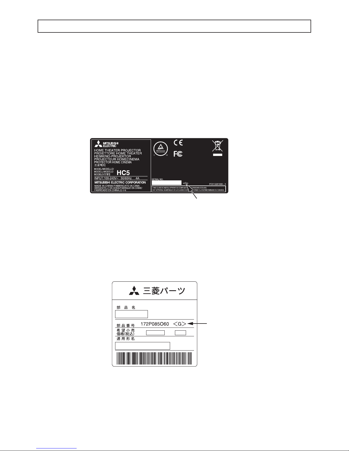
2. Check the presence of <G> marking on the rating plate to distinguish RoHScompliant product from non-RoHS-compliant product.
<G> marking
With <G> marking: RoHS-compliant product
Without <G> marking: Non-RoHS-compliant product
<Sample>
3. Labels of RoHS-compliant service parts bear <G> marking for identifi cation purpose.
<Sample>
4. Don’t use non-RoHS-compliant parts with RoHS-compliant products.
5. Service parts for RoHS-compliant products are listed in the parts catalog contained
in the service manual.
Parts Name
Model Name
Parts No.
E05R
Mark position
Mark position

- 3 -
SPECIFICATIONS
• Weight and dimensions shown are approximate.
• Design and specifications are subject to change without
notice.
• Rated power supply
: 100-240 V AC, 50/60 Hz
• Power consumption
: 4.0A
• Display technology : 0.61 inch SXRDTM panel
• Pixels : 1,920x1,080= 2,073,600 pixels
• Projection lens
: F=3.2-3.9, f=21.4-38.5 mm
• Light source lamp : 230 W
• Picture Size
:
50-200 inch (16:9)
• PC compatibility :
1,920 x 1,080
• Video compatibility
: NTSC / NTSC 4.43 / PAL (including PAL-M, N)
/ SECAM / PAL-60
Component Video(480i/p, 576i/p, 720p, 1080i/p)
• S-Video input : Luminance signal;
1.0 Vp-p 75Ω (negative sync)
Chroma signal;
0.286 Vp-p 75Ω (burst signal)
• Video input
: 1.0 Vp-p 75Ω(negative sync)
• Analog RGB input : RGB: 0.7 Vp-p 75Ω(negative sync)
YPbPr/YCbCr: Y-> 1.0 Vp-p (negative sync)
PbPr/CbCr-> 0.7 Vp-p
HD/CS: TTL level(positive or negative)
VD: TTL level(positive or negative)
• Digital input
: HDMI interface (TMDS single link)
• Control connector :
Serial terminal (RS-232C) (D-sub 9 pin)
• Outside dimensions : 482 x 215 x 530mm (width x height x depth)
• Weight
: 14.5kg
• Operating temperature
: 5°C - 35°C

- 4 -
CONTENTS
– FILE “COVERPGE” –
NOTES FOR SERVICING RoHS-COMPLIANT PRODUCTS ............................................................................... 2
SPECIFICATIONS ................................................................................................................................................. 3
CONTENTS ........................................................................................................................................................... 4
– FILE “DIAGNO” –
DIAGNOSIS INFORMATION ................................................................................................................................. 1
STATUS LED indicator ..................................................................................................................................... 1
SPECIFICATION OF INPUT SIGNALS IN EACH INPUT OF THE PROJECTOR ................................................ 2
– FILE “EXPOSED” –
TRADE MARK, REGISTERED TRADEMARK ...................................................................................................... 1
PRODUCT SAFETY NOTICE ............................................................................................................................... 1
SAFETY PRECAUTIONS ...................................................................................................................................... 2
PRECAUTIONS FOR RESOLDERING ................................................................................................................. 3
PCB LOCATION .................................................................................................................................................... 4
EXPOSED VIEW ................................................................................................................................................... 6
Chassis ASSY 1 ............................................................................................................................................... 6
Chassis ASSY 2 ............................................................................................................................................... 8
Chassis ASSY 3 ............................................................................................................................................... 10
DISASSEMBLY ..................................................................................................................................................... 12
1. Removal of the Top cover ASSY .................................................................................................................. 12
2. Removal of the KEY SWITCH PCB ASSY ................................................................................................... 12
3. Removal of the IR PCB ASSY (FRONT)...................................................................................................... 12
4. Removal of the LAMP COVER PCB ASSY ................................................................................................. 12
5. Removal of the TEMP SENSOR PCB ASSY (POWER) .............................................................................. 13
6. Removal of the LAMP POWER PCB ASSY ................................................................................................. 13
7. Removal of the TEMP SENSOR PCB ASSY (OUTLET) ............................................................................. 14
8. Removal of the Fan (Inlet) / Fan (Outlet) ..................................................................................................... 14
9. Removal of the Power fan ........................................................................................................................... 15
10. Removal of the POWER PCB ASSY ......................................................................................................... 15
11. Removal of the Duct fan (Inlet) .................................................................................................................. 16
12. Removal of the LFT PCB ASSY ................................................................................................................. 17
13. Removal of the MEMC PCB ASSY ............................................................................................................ 17
14. Removal of the SCALER PCB PCB ASSY / HDMI PCB ASSY ................................................................. 17
15. Removal of the Lamp unit / Optical unit / Cooling fan (optical) .................................................................. 18
16. Removal of the IR PCB ASSY (REAR) ...................................................................................................... 19
17. Removal of the Thermostat ....................................................................................................................... 19
18. Removal of the I/O PCB ASSY / TEMP SENSOR PCB ASSY (INLET) ..................................................... 20
19. Removal of the AC inlet ............................................................................................................................. 20
LEAD DRESS ........................................................................................................................................................ 21
LABEL POSITION ................................................................................................................................................. 49
PACKING ............................................................................................................................................................... 50
– FILE “MAINTENA” –
REPLACING THE LAMP ....................................................................................................................................... 1
MAINTENANCE .................................................................................................................................................... 4
DOWNLOAD OF THE FIRMWARE ....................................................................................................................... 5
LIFE TIME OF THE CONSUMABLE PARTS ........................................................................................................ 8
– FILE “PCCONTRL” –
Controlling the projector using a personal computer ............................................................................................. 1
– FILE “PARTSLST” –
PARTS LIST .......................................................................................................................................................... 1
PCB LOCATION .............................................................................................................................................. 2
EXPOSED VIEW ............................................................................................................................................. 3
Chassis ASSY 1 ......................................................................................................................................... 3
Chassis ASSY 2 ......................................................................................................................................... 4
Chassis ASSY 3 ................................................................................................................
......................... 5
P
ACKING AND ACCESSORY ......................................................................................................................... 6
PACKING ................................................................................................................................................... 6
ACCESSORY ............................................................................................................................................. 6
ELECTRICAL PARTS AND OTHERS .............................................................................................................. 7
– FILE “SHEMATC” –
BLOCK DIAGRAM ........................................................................................................................................... B-1
SCHEMATIC DIAGRAMS ................................................................................................................................ C-1
- 1 -
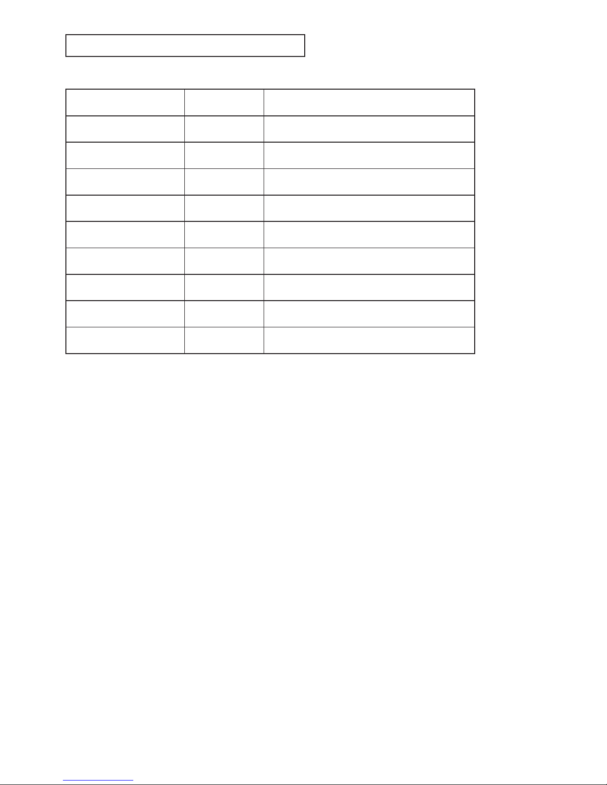
DIAGNOSIS INFORMATION
STATUS LED indicator
LED Indication Numbers of flash Failure
Red / orange alternately
1
E2PROM communication error
Green fl ash 2 Fan error
Green / orange alternately 1 Temp error
Green / orange alternately 2 PCB-MEMC error
Green / orange alternately 3 Lamp cover error (Lamp cover switch open.)
Green fl ash 1 PCB-POWER error
Orange fl ash 2 MCU-DDB communication error
Orange fl ash 3
1. Scaler doesn't finish the initial work.
2. MCU-Reon communication error
Red fl ash 1
Others error
Note : Check the STATUS LED indicator after the projector fi nishes the cooling process.
Flash (On 0.5Sec, Off 0.5Sec.)
- 2 -
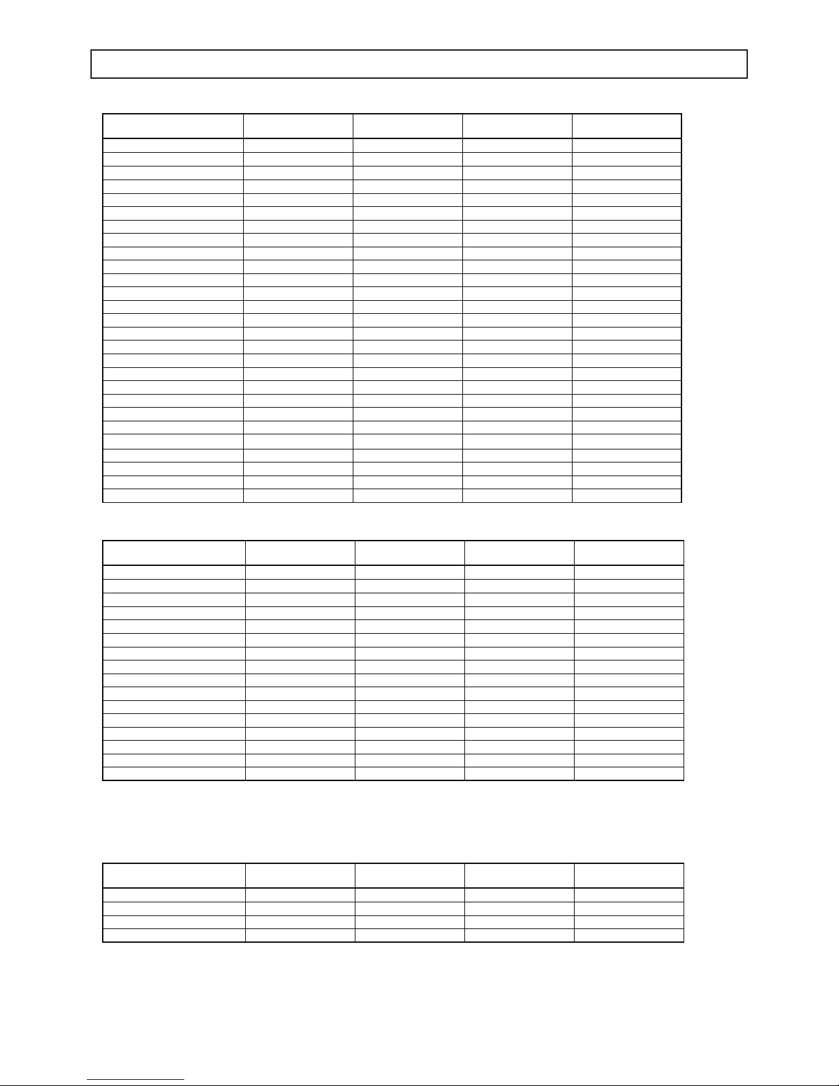
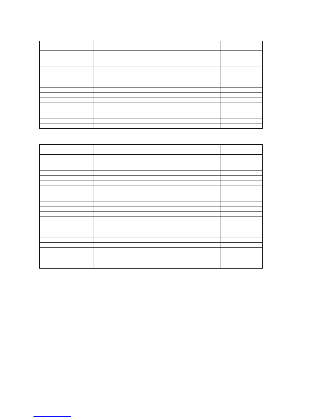
SPECIFICATION OF INPUT SIGNALS IN EACH INPUT OF THE PROJECTOR
HDMI
Signal mode
Resolution
(H x V)
Horizontal frequency
(kHz)
Vertical frequency
(Hz)
Normal mode
(H x V)*1
480i60.00Hz(Double Rate) - 15.75 60.00 1440x1080
480i59.94Hz(Double Rate) - 15.73 59.94 1440x1080
576i50.00Hz(Double Rate) - 15.63 50.00 1440x1080
480p 60.00Hz - 31.50 60.00 1440x1080
480p 59.94Hz - 31.47 59.94 1440x1080
576p 50.00Hz - 31.25 50.00 1440x1080
720p 60.00Hz - 45.00 60.00 1920x1080
720p 59.94Hz - 44.96 59.94 1920x1080
720p 50.00Hz - 37.50 50.00 1920x1080
1080i 60.00Hz - 33.75 60.00 1920x1080
1080i 59.94Hz - 33.72 59.94 1920x1080
1080i 50.00Hz - 28.13 50.00 1920x1080
1080p 60.00Hz - 67.50 60.00 1920x1080
1080p 59.94Hz - 67.43 59.94 1920x1080
1080p 50.00Hz - 56.25 50.00 1920x1080
1080p 24.00Hz - 27.00 24.00 1920x1080
1080p 23.98Hz - 26.97 23.98 1920x1080
VGA 60.00Hz 640x480 31.50 60.00 1440x1080
VGA 59.94Hz 640x480 31.47 59.94 1440x1080
SVGA 60Hz 800x600 37.88 60.00 1440x1080
XGA/60Hz 1024x768 48.36 60.00 1440x1080
WXGA 60Hz 1280x768 47.76 60.00 1800x1080
WXGA+ 60Hz 1440x900 55.92 60.00 1728x1080
SXGA+ 60 1400x1050 65.32 59.98 1440x1080
SXGA 60Hz 1280x1024 63.98 60.00 1350x1080
WSXGA+ 60Hz 1680x1050 65.22 60.00 1728x1080
WUXGA 60Hz 1920x1200 74.04 59.95 1728x1080
HDMI-3D
Signal mode Resolution
(H x V)
Horizontal frequency
(kHz)
Vertical frequency
(Hz)
Normal mode
(H x V)*1
Frame Packing 720p50 - 50.00 75.00 1920x1080
Frame Packing 720p59 - 59.94 89.91 1920x1080
Frame Packing 720p60 - 60.00 90.00 1920x1080
Frame Packing 1080p23 - 23.98 53.95 1920x1080
Frame Packing 1080p24 - 24.00 54.00 1920x1080
Side-by-Side 1080p50(Half ) - 50.00 56.25 1920x1080
Side-by-Side 1080p59(Half ) - 59.94 67.43 1920x1080
Side-by-Side 1080p60(Half ) - 60.00 67.50 1920x1080
Side-by-Side 1080i50(Half ) - 50.00 28.13 1920x1080
Side-by-Side 1080i60(Half ) - 60.00 33.75 1920x1080
Side-by-Side 1080i59(Half ) - 59.94 33.72 1920x1080
Top-and-Bottom 1080p24 - 24.00 27.00 1920x1080
Top-and-Bottom 1080p23 - 23.98 26.97 1920x1080
Top-and-Bottom 720p50 - 50.00 37.50 1920x1080
Top-and-Bottom 720p60 - 60.00 45.00 1920x1080
Top-and-Bottom 720p59 - 59.94 44.96 1920x1080
Video / S-Video
Signal mode Resolution
(H x V)
Horizontal frequency
(kHz)
Vertical frequency
(Hz)
Normal mode
(H x V)*1
NTSC(3.58/4.43) 712x483 15.73 59.94 1440x1080
PAL/PAL-N 702x575 15.63 50.00 1440x1080
PAL-M 712x483 15.73 59.94 1440x1080
SECAM 702x575 15.63 50.00 1440x1080
- 3 -
*1 This mode shows the display area when Aspect Ratio in
the Screen menu is set to Standard.
Important:
r Some computers aren’t compatible with the projector.
r The projector’s maximum resolution is 1920 x 1080
pixels. It may not display images of higher resolutions
than 1920 x 1080 correctly.
r If the resolution and frequency of your computer
aren’t shown on the table, nd the compatible
resolution and frequency by changing the resolution
of your computer.
r This projector supports only 5 lines format (R, G, B, H,
V) in Computer input and does not support 4 lines
format (R, G, B, Composite Sync).
Component
Signal mode Resolution
(H x V)
Horizontal frequency
(kHz)
Vertical frequency
(Hz)
Normal mode
(H x V)*1
480i 60.00Hz - 15.75 60.00 1440x1080
480i 59.94Hz - 15.73 59.94 1440x1080
576i 50.00Hz - 15.63 50.00 1440x1080
480p 60.00Hz - 31.50 60.00 1440x1080
480p 59.94Hz - 31.47 59.94 1440x1080
576p 50.00Hz - 31.25 50.00 1440x1080
720p 60.00Hz - 45.00 60.00 1920x1080
720p 59.94Hz - 44.96 59.94 1920x1080
720p 50.00Hz - 37.50 50.00 1920x1080
1080i 60.00Hz - 33.75 60.00 1920x1080
1080i 59.94Hz - 33.72 59.94 1920x1080
1080i 50.00Hz - 28.13 50.00 1920x1080
1080p 60.00Hz - 67.50 60.00 1920x1080
1080p 59.94Hz - 67.43 59.94 1920x1080
1080p 50.00Hz - 56.25 50.00 1920x1080
PC Signal
Signal mode Resolution
(H x V)
Horizontal frequency
(kHz)
Vertical frequency
(Hz)
Normal mode
(H x V)*1
VGA 60 640x480 31.50 60.00 1440x1080
VGA 72 640x480 37.90 72.00 1440x1080
VGA 75 640x480 37.50 75.00 1440x1080
VGA 85 640x480 43.30 85.00 1440x1080
SVGA 56 800x600 35.20 56.00 1440x1080
SVGA 60 800x600 37.90 60.00 1440x1080
SVGA 72 800x600 48.10 72.00 1440x1080
SVGA 75 800x600 46.90 75.00 1440x1080
SVGA 85 800x600 53.70 85.00 1440x1080
XGA 60 1024x768 48.40 60.00 1440x1080
XGA 70 1024x768 56.50 70.00 1440x1080
XGA 75 1024x768 60.02 75.03 1440x1080
XGA 85 1024x768 68.70 85.00 1440x1080
WXGA 60 1280x768 47.76 60.00 1800x1080
WXGA+ 60 1440x900 55.92 60.00 1728x1080
SXGA 60 1280x1024 63.98 60.02 1440x1080
SXGA+ 60 1400x1050 64.74 59.95 1350x1080
WSXGA+ 60 1680x1050 65.22 60.00 1728x1080
1920x1080@60 1920x1080 67.50 60.00 1920x1080
MAC13" 640x480 35.00 66.67 1440x1080
MAC16" 832x624 49.11 75.09 1440x1080
MAC19" 1024x768 60.24 74.93 1440x1080

- 1 -
Microsoft Windows 95/98/Me/Vista/XP are either registered trademarks or trademarks of Microsoft Corporation in the United
States and/or other countries.
Other brand or product names are trademarks or registered trademarks of their respective holders.
TRADEMARK, REGISTERED TRADEMARK
Many electrical and mechanical parts in the projector have special safety related characteristics. These characteristics are
often not evident from visual inspection nor can the protection afforded by them necessarily be obtained by using replacement
components rated for higher voltage, etc. Replacement parts which have these special safety characteristics are identifi ed in
this service manual. Electrical components having such features are identifi ed by shading on the schematic diagram and the
parts list of this service manual and by the supplementary sheet for this chassis to be issued subsequently.
PRODUCT SAFETY NOTICE
- 2 -
Europe, other than USA
NOTICE: Observe all cautions and safety related notes located inside the cabinet and on the chassis.
Warning
1. An isolation transformer should be used between the projector and the AC supply point before any test/service is
performed on a LIVE chassis projector.
2. Operation of this projector outside the cabinet or with the cover removed, involves a shock hazard from the projector
power supplies. Work on the projector should not be attempted by anyone who is not thoroughly familiar with precautions
necessary when working on high voltage equipment.
3. When service is required, observe the original lead dressing. Extra precaution should be given to assure correct lead
dressing in the high voltage area. Where a short-circuit has occurred, replace those components that indicate evidence of
overheating.
Leakage current cold check
Before returning the projector to the customer, it is recommended that leakage current be measured according to the
following methods.
With the AC plug removed from the AC source, place a jumper across the two AC plug prongs. Turn the projector AC switch
on. Using an 500 V D.C. Insulation Tester, connect one lead to the jumpered AC plug and touch the other lead to each
exposed metal part (screwheads, etc.), particularly any exposed metal part having a return path to the chassis. Exposed
metal parts having a return path to the chassis should have a minimum resistance reading of 4 M
Ω
. Any resistance below this
value indicates an abnormality which requires corrective action.
V
S1
S2
GH
(grounding)
open
Grounding supply conductor
B
Insulating table
Projector
A
AC milliammeter
Figure
A
C 100 to 240 V
North america
NOTICE: Observe all cautions and safety related notes located inside the cabinet and on the chassis.
Warning
1. Operation of this projector outside the cabinet or with the cover removed presents a shock hazard from the projector
power supplies.
2. When a short-circuit has occurred, replace those components that indicate evidence of overheating.
3. Grounding circuit continuity is vital for safe operation of equipment. Do not remove ground connection while the power
cord is still connected to the supply. Disconnect supply before servicing.
Leakage current check
Before returning the projector to the customer, it is recommended that leakage current be measured according to the
following methods.
1. Cold check
With the AC plug removed from the AC 100 to 240 V, place a jumper across the two AC plug prongs. Turn the projector
AC switch on. Using an ohm-meter, connect one lead to the AC plug and touch the other lead to each exposed metal
part (metal cabinet, screwheads, metal overlays, etc.), particularly any exposed metal part having a return path to the
chassis. Exposed metal parts having a return path to the chassis should have a minimum resistance reading of 1 M
Ω
. Any
resistance below this value indicates an abnormality which requires corrective action. Exposed metal parts not having a
return path to the chassis will indicate an open circuit.
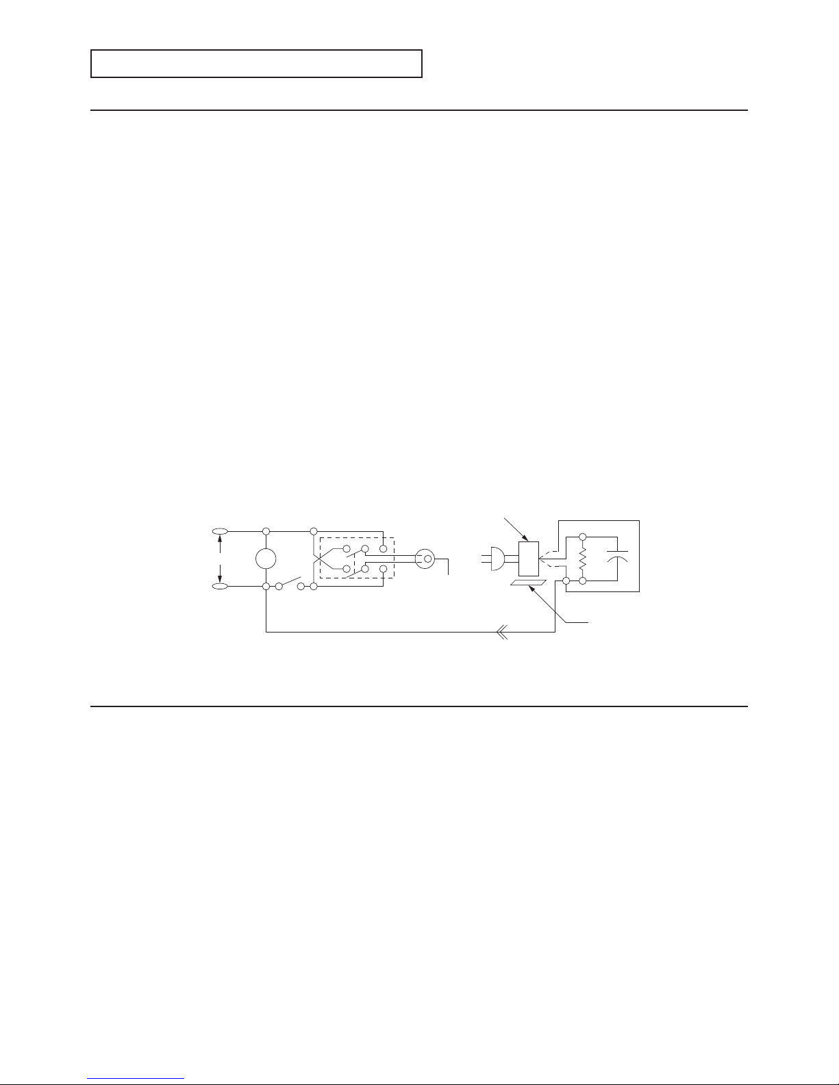
2. Hot check
Use the circuit in fi gure to perform this test.
(1) With switch S1 open, connect the projector to the measuring circuit. Immediately after connection, measure the
leakage current using both positions of switch S2, and with the switching devices in the projector in all of their
operating positions.
(2) Switch S1 is then closed, energizing the projector. Immediately after closing the switch, measure the leakage current
using both positions of switch S2, and with the switching devices in the projector in all of their operating positions.
Current measurements of items (1) and (2) are to be repeated after the projector has reached thermal stabilization.
The leakage current must not be more than 0.5 milliampere.
SAFETY PRECAUTIONS
- 3 -
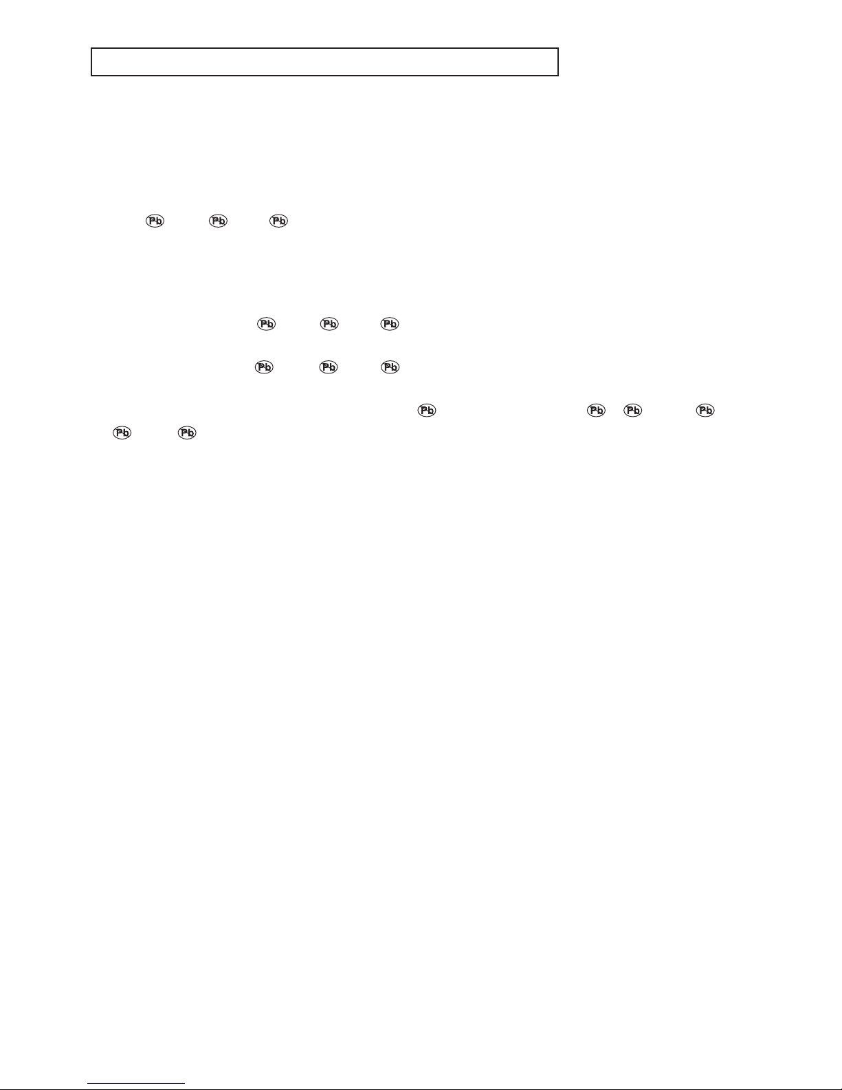
Lead-free solder is handled in a different way from eutectic solder. See below for details.
How to distinguish circuit boards using lead-free solder from those using
eutectic solder
Circuit boards using lead-free solder
A mark of Solder, Joints, PCA or LFS (for limited marking space) is printed near the board assembly number on
the component side.
Circuit boards using eutectic solder
Circuit boards using eutectic solder are divided into two groups.
- Boards having no mark of
Solder, Joints, PCA or LFS (for limited marking space) near the board assembly
number.
- Boards having a mark of
Solder, Joints, PCA or LFS (for limited marking space) that is painted out by a
feltpen near the board assembly number.
* Only when there is a limited marking space on the board,
Solder may be indicated as S, Joints as J, and
PCA as P.
* Circuit boards using lead-free solder and those using eutectic solder may be used together in the same product.
Instructions for resoldering
- For circuit boards using lead-free solder, use lead-free solder.
- For circuit boards using eutectic solder, use eutectic solder.
- Separate the soldering iron for lead-free solder from that for eutectic solder completely for use.
(It is prohibited to use a same soldering iron for lead-free solder and eutectic solder.)
- For lead-free solder, it is advisable to use a soldering iron of at least 40 W because lead-free solder has a melting point
approx. 35°C higher than that of eutectic solder as conventionally used. For wire solder, use M705ESC made by Senju
Metal Industry Co., Ltd.
- To remove solder, you can use desoldering wires for eutectic solder as conventionally used.
PRECAUTIONS FOR RESOLDERING
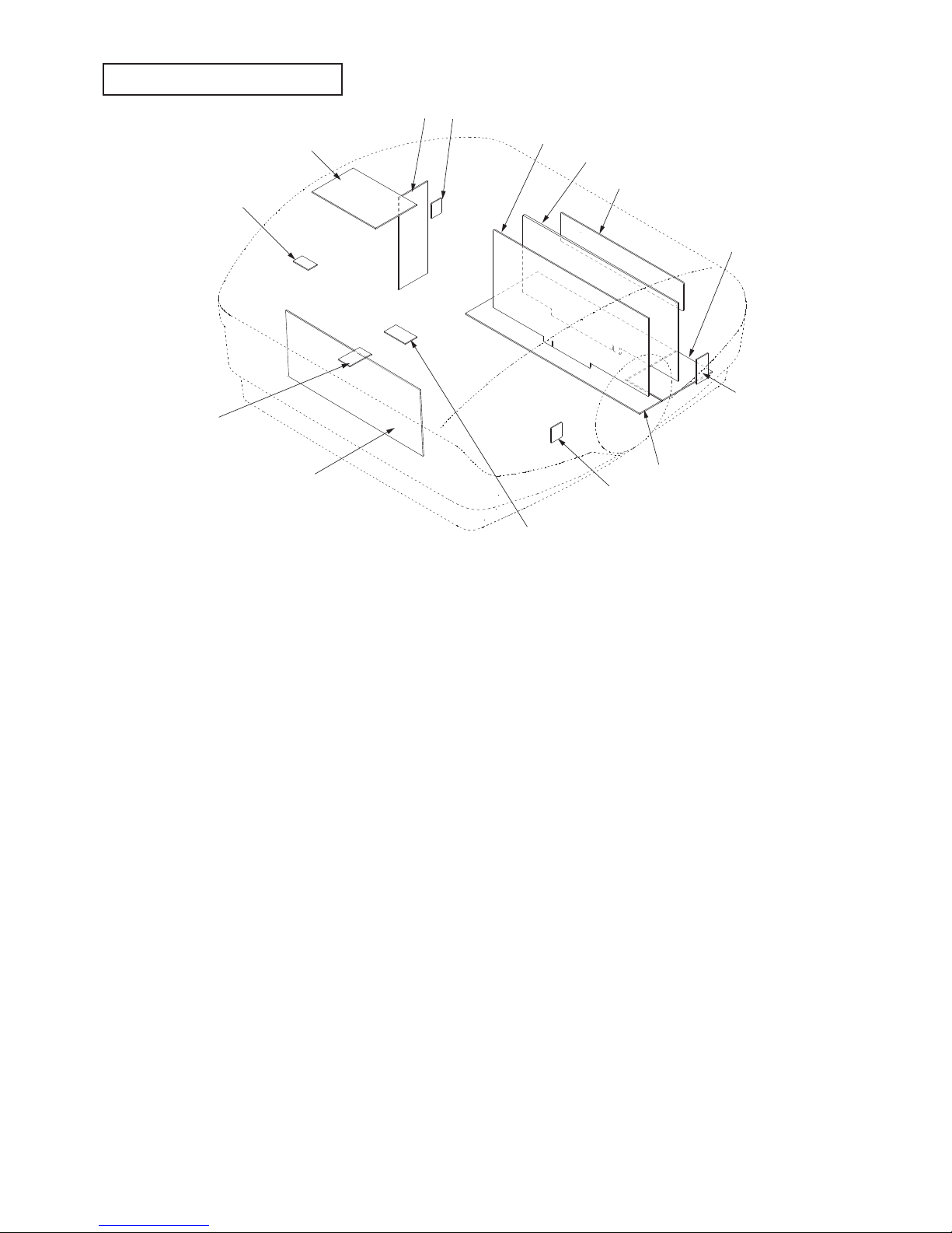
- 4 -
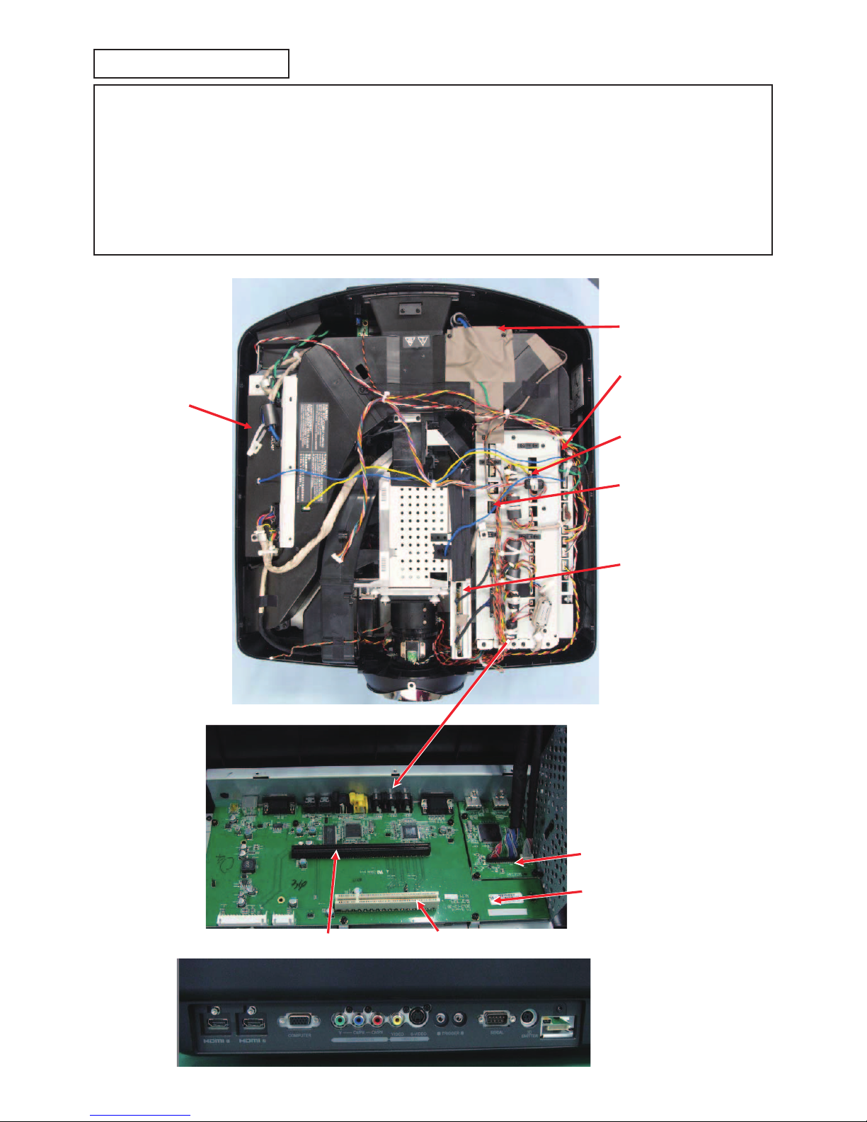
PCB LOCATION
Fig.1
4
8
1
3
5
2
6
7
11
10
9
12
13
14
- 5 -
Parts list : See page 2 of PARTS LIST
Item No. Part name
1 I/O PCB ASSY
2 TEMP SENSOR PCB ASSY (INLET)
3 HDMI PCB ASSY
4 LFT PCB ASSY
5 SCALER PCB ASSY
6 MEMC PCB ASSY
7 IR PCB ASSY (REAR)
8 LAMP POWER PCB ASSY
9 KEY SWITCH PCB ASSY
10 LAMP COVER PCB ASSY
11 TEMP SENSOR PCB ASSY (POWER)
12 POWER PCB ASSY
13 TEMP SENSOR PCB ASSY (OUTLET)
14 IR PCB ASSY (FRONT)
Table 1
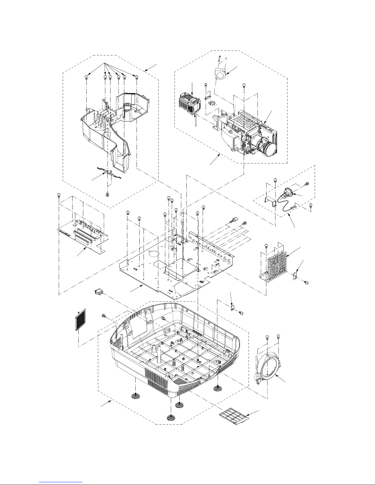
- 6 -
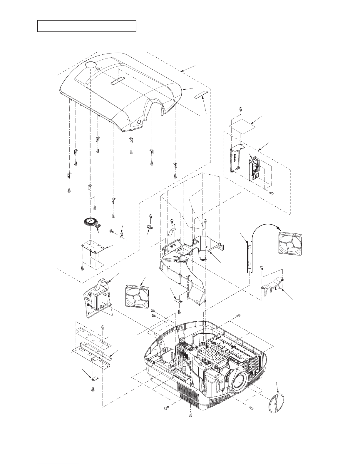
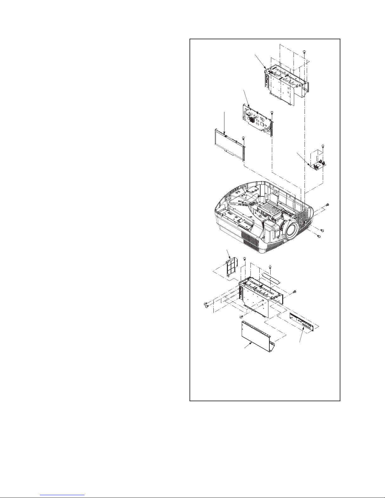
Chassis ASSY 1
Fig.2-1
3
8
9
7
7
77
7
7
7
7
Hx1
14
13
Nx4
Qx11Ex2
Jx1
Gx1
6
10
15
18
20
Px2
17
5
4
Fx6
2
Ax2
16
Rx1
Qx2
Cx2
Kx4
11
12
Lx1
Cx3
Bx1
Cx3
Dx2
1
Mx2
Hx1
Hx1
Hx1
Hx1
Hx1
Hx1
Hx1
19
EXPOSED VIEW
- 7 -
Part name Number of screw
1.Lens cap None
2.Lamp cover unit Ax2, Ex2
3.Top cover ASSY Bx1, Cx8, Dx2
4.KEY SWITCH PCB ASSY Fx6
5.Key ASSY None
6.IR PCB ASSY(Front) Gx1
7.Cover holder Hx8
8.WW Logo inlay None
9.Top cover unit None
10.LAMP COVER PCB ASSY Jx1
11.Power shield plate 1 Kx4
12.TEMP SENSOR PCB ASSY (POWER) Lx1
13.Lamp power sheet Mx2
14.Lamp power ASSY Mx2
15.LAMP POWER PCB ASSY Nx4
16.Optical cover Px2
17.Top duct ASSY Qx13
18.TEMP SENSOR PCB ASSY (OUTLET) Rx1
19.Fan(Inlet) None
20.Fan(Outlet) None
21.Power sheet Kx3
Table 2-1
Parts list : See page 3 of PARTS LIST
- 8 -
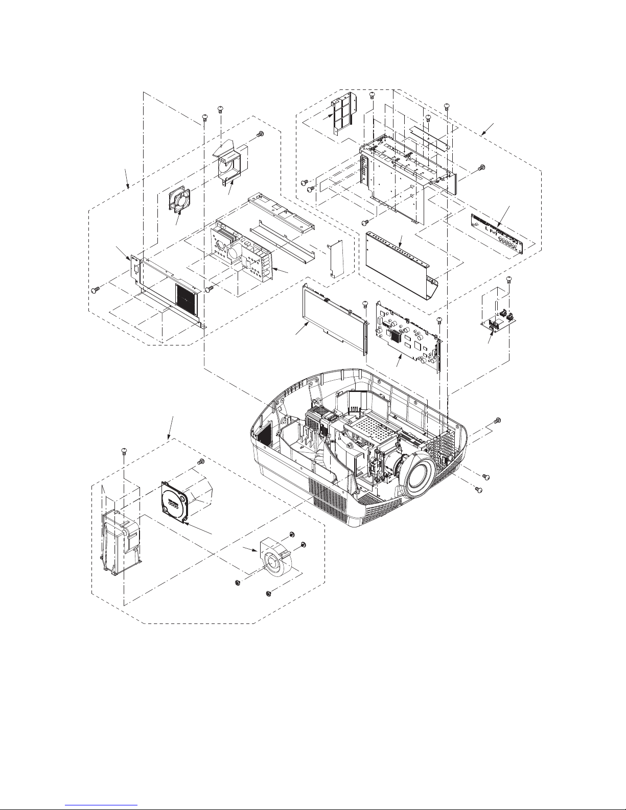
Chassis ASSY 2
Fig.2-2
Ax2
1
Bx1
2
Cx3
3
4
Dx6
Ex6
5
6
Fx5
7
Gx6
8
9
Hx8
10
Jx3
Jx2
Kx2
Kx2
11
Jx3
12
Lx4
13
14
15
Mx1
Mx1
Nx1
Nx1
Px2
Qx4
- 9 -
Part name Number of screw
1.Power unit Ax2, Bx1
2.Power fan holder ASSY Cx3
3.Power fan None
4.Power shield plate 2 Dx6
5.POWER PCB ASSY Ex6
6.Duct unit (Inlet) Fx5
7.Duct cover (Inlet) Gx6
8.Duct fan (Inlet) None
9.MEMC/scaler shield plate ASSY Hx8
10.Scaler shield plate 1 Jx8
11.Scaler shield plate 2 Kx4
12.LFT PCB ASSY Lx4
13.MEMC PCB ASSY Mx2
14.SCALER PCB ASSY Nx2
15.HDMI PCB ASSY Px2, Qx4
Table 2-2
Parts list : See page 3 of PARTS LIST
- 10 -
Chassis ASSY 3
Fig.2-3
Ax6
1
Bx2
2
Cx2
3
Dx1
4
5
Ex2
Fx1
Gx2
6
7
8
Hx3
Jx2
Kx2
9
10
Lx4
Mx4
Nx7
11
12
Px5
Qx1
13
Rx2
Rx2
14
15
15
15
15
16
Sx3
Sx5
Sx1
Sx1Sx1
Sx1
Sx1
Sx1
17
Tx2
- 11 -
Part name Number of screw
1.Bottom duct ASSY Ax6, Bx2
2.Thermostat Cx2
3.IR PCB ASSY (REAR) Dx1
4.AC inlet ASSY Ex2, Fx1
5.AC inlet Gx2
6.Optical ASSY Hx3
7.Lamp unit Jx2
8.Cooling fan (optical) Kx2
9.Optical unit Tx2
10.I/O PCB ASSY Lx4, Mx4, Nx7
11.HDMI shield plate Px5
12.TEMP SENSOR PCB ASSY (INLET) Qx1
13.Lens cover unit Rx4
14.Filter None
15.Adjustment foot None
16.Bottom plate Sx14
17.Bottom cover unit None
Table 2-3
Parts list : See page 4 of PARTS LIST
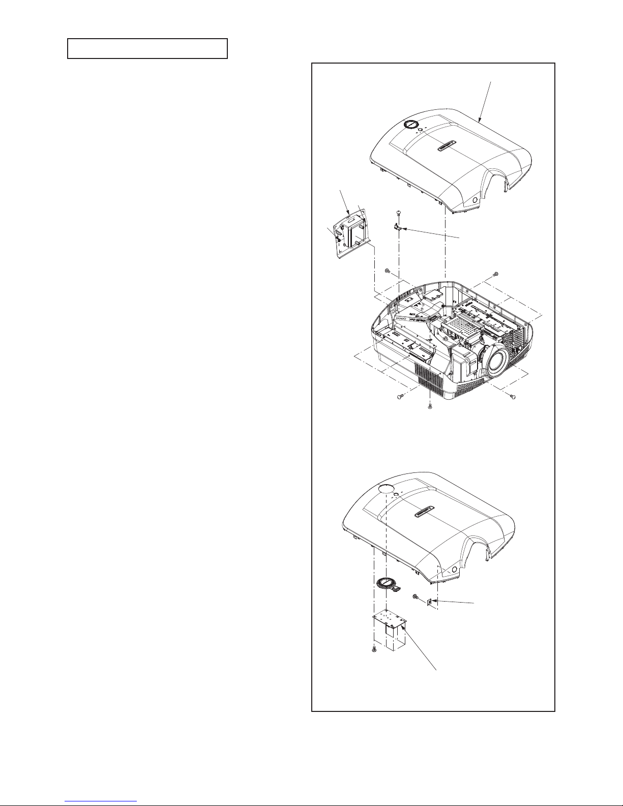
- 12 -
Fig.3-1
Note : On the lead connector, the connector name
isn't indicated. When disconnecting the lead
connector, place labels (
INDEX LABELs
) bearing
the reference markings (connector names) near
the lead connectors and the connectors on the
board to prevent wrong disconnection. After
re-connecting the lead connectors, remove the
labels. To disassemble the product, it is required to
cut the BAND KMs that clamp the lead connectors.
Therefore, when re-assembling the product,
prepare and use the specified BAND KMs. For
the part number of the BAND KM, refer to PARTS
LIST.
For the reference markings of the lead connectors,
see pages D23 to D26.
For the connector names of the fans and motors,
see pages D35 to D48.
1.
Removal of the Top cover ASSY
1. Loose the two screws (a) and remove the Lamp cover
ASSY as shown in Fig. 3-1.
2. Remove the screw (b), eight screws (c) and two screws
(d) as shown in Fig. 3-1.
3. Disconnect the connector on the KEY SWITCH PCB
ASSY and remove the Top cover ASSY as shown in Fig.
3-1.
2.
Removal of the KEY SWITCH PCB ASSY
1. Remove the Top cover ASSY according to “1. Removal
of the Top cover ASSY”.
2. Remove the six screws (f) and KEY SWITCH PCB ASSY
as shown in Fig. 3-1.
3.
Removal of the IR PCB ASSY (FRONT
)
1. Remove the Top cover ASSY according to “1. Removal
of the Top cover ASSY”.
2. Disconnect the connector on the IR PCB ASSY
(FRONT) as shown in Fig. 3-1.
3. Remove the screw (g) and IR PCB ASSY (FRONT) as
shown in Fig. 3-1.
4. Removal of the LAMP COVER
PCB ASSY
1. Remove the Top cover ASSY according to “1. Removal
of the Top cover ASSY”.
2. Disconnect the connector on the LAMP COVER PCB
ASSY as shown in Fig. 3-1.
3. Remove the screw (e) and LAMP COVER PCB ASSY as
shown in Fig. 3-1.
ax1
cx2
cx3
cx3
dx2
bx1
ex1
ax1
Top cover ASSY
LAMP COVER
PCB ASSY
Lamp cover unit
DISASSEMBLY
fx6
gx1
KEY SWITCH PCB ASSY
IR PCB ASS
Y
(FRONT)
- 13 -
ax4
bx1
dx4
cx2
70mm
Lamp power
sheet
LAMP POWER
PCB ASSY
Lamp power ASSY
TEMP SENSOR
PCB ASSY
(POWER)
Power shield
plate 1
Power sheet
Fig.3-2
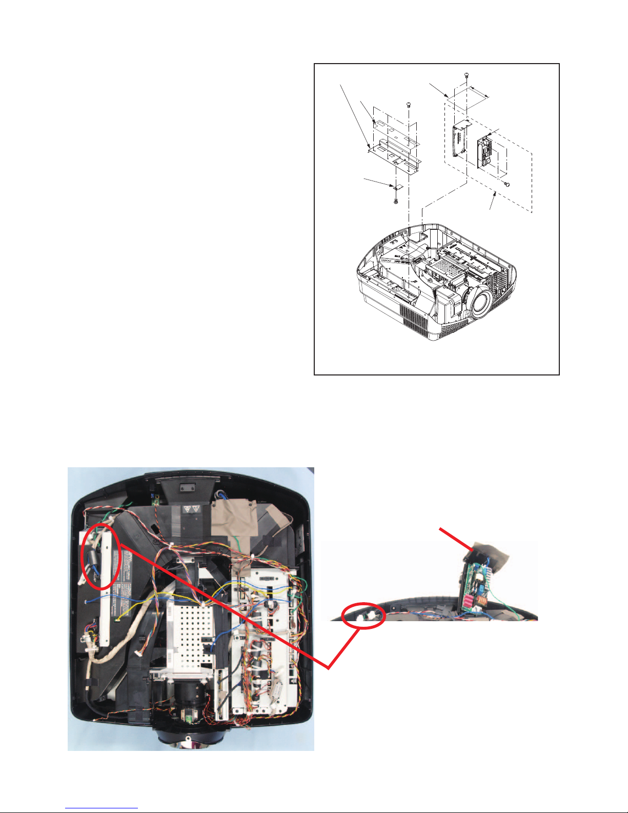
5. Removal of the TEMP SENSOR
PCB ASSY (POWER)
1. Remove the Top cover ASSY according to “1. Removal
of the Top cover ASSY”.
2. Remove the four screws (a) and Power shield plate 1 as
shown in Fig. 3-2.
3. Disconnect the connector on the TEMP SENSOR PCB
ASSY (POWER) as shown in Fig. 3-2.
4. Remove the screw (b) and TEMP SENSOR PCB ASSY
(POWER) as shown in Fig. 3-2.
6. Removal of the LAMP POWER
PCB ASSY
1. Remove the Top cover ASSY according to “1. Removal
of the Top cover ASSY”.
2. Remove the two screws (c) and Lamp power ASSY as
shown in Fig. 3-2.
Note) The LAMP POWER SHEET has no screw holes.
Insert the screw, piercing the LAMP POWER
SHEET.
3. Disconnect all connectors on the LAMP POWER PCB
ASSY as shown in Fig. 3-2.
4. Remove the four screws (d) and LAMP POWER PCB
ASSY as shown in Fig. 3-2.
Note) The Lamp power sheet is not reusable.
Lamp power ASSY
LEAD DRESS
To remove the LAMP POWER PCB ASSY, disconnect the
connector and loosen the lead wire.
- 14 -
bx2
cx11
cx2
dx1
ax2
Top duct ASSY
TEMP SENSOR
PCB ASSY
(OUTLET)
Optical cover
Fan (Inlet)
Fan
(Outlet)
Optical cover
Fig.3-3
7. Removal of the TEMP SENSOR
PCB ASSY (OUTLET)
1. Remove the Top cover ASSY according to “1. Removal
of the Top cover ASSY”.
2. Remove the Power shield plate 1 according to “5.
Removal of the TEMP SENSOR PCB ASSY (POWER)”.
3. Remove the Lamp power ASSY according to “6.
Removal of the LAMP POWER PCB ASSY”.
4. Remove the two screws (a) and Optical cover as shown
in Fig. 3-3.
5. Remove the two screws (b), thirteen screws (c) and Top
duct ASSY as shown in Fig. 3-3.
6. Disconnect the connector on the TEMP SENSOR PCB
ASSY (OUTLET) as shown in Fig. 3-3.
7. Remove the screw (d) and TEMP SENSOR PCB ASSY
(OUTLET) as shown in Fig. 3-3.
8. Removal of the Fan (Inlet) / Fan
(Outlet)
1. Remove the Top cover ASSY according to “1. Removal
of the Top cover ASSY”.
2. Remove the Power shield plate 1 according to “5.
Removal of the TEMP SENSOR PCB ASSY (POWER)”.
3. Remove the Lamp power ASSY according to “6.
Removal of the LAMP POWER PCB ASSY”.
4. Remove the Top duct ASSY according to “7. Removal of
the TEMP SENSOR PCB ASSY (OUTLET)”.
5. Disconnect the connectors on the LFT PCB ASSY as
shown in Fig. 3-6.
6. Remove the Fan (Inlet), Fan (Outlet) as shown in Fig.
3-3.
- 15 -
ax2
dx6
ex6
cx3
bx1
Power unit
Power fan
POWER PCB ASSY
Power shield
plate 2
Fig.3-4
9. Removal of the Power fan
1. Remove the Top cover ASSY according to “1. Removal
of the Top cover ASSY”.
2. Remove the Power shield plate 1 according to “5.
Removal of the TEMP SENSOR PCB ASSY (POWER)”.
3. Remove the two screws (a), screw (b) and Power unit as
shown in Fig. 3-4.
4. Disconnect the connector on the LFT PCB ASSY as
shown in Fig. 3-6.
5. Remove the three screws (c) and Power fan as shown in
Fig. 3-4.
10. Removal of the POWER PCB ASSY
1. Remove the Top cover ASSY according to “1. Removal
of the Top cover ASSY”.
2. Remove the Power shield plate 1 according to “5.
Removal of the TEMP SENSOR PCB ASSY (POWER)”.
3. Remove the Power unit according to “9. Removal of the
Power fan”.
4. Remove the six screws (d) and Power shield plate 2 as
shown in Fig. 3-4.
5. Disconnect all connectors on the POWER PCB ASSY as
shown in Fig. 3-4.
6. Remove the six screws (e) and POWER PCB ASSY as
shown in Fig. 3-4.
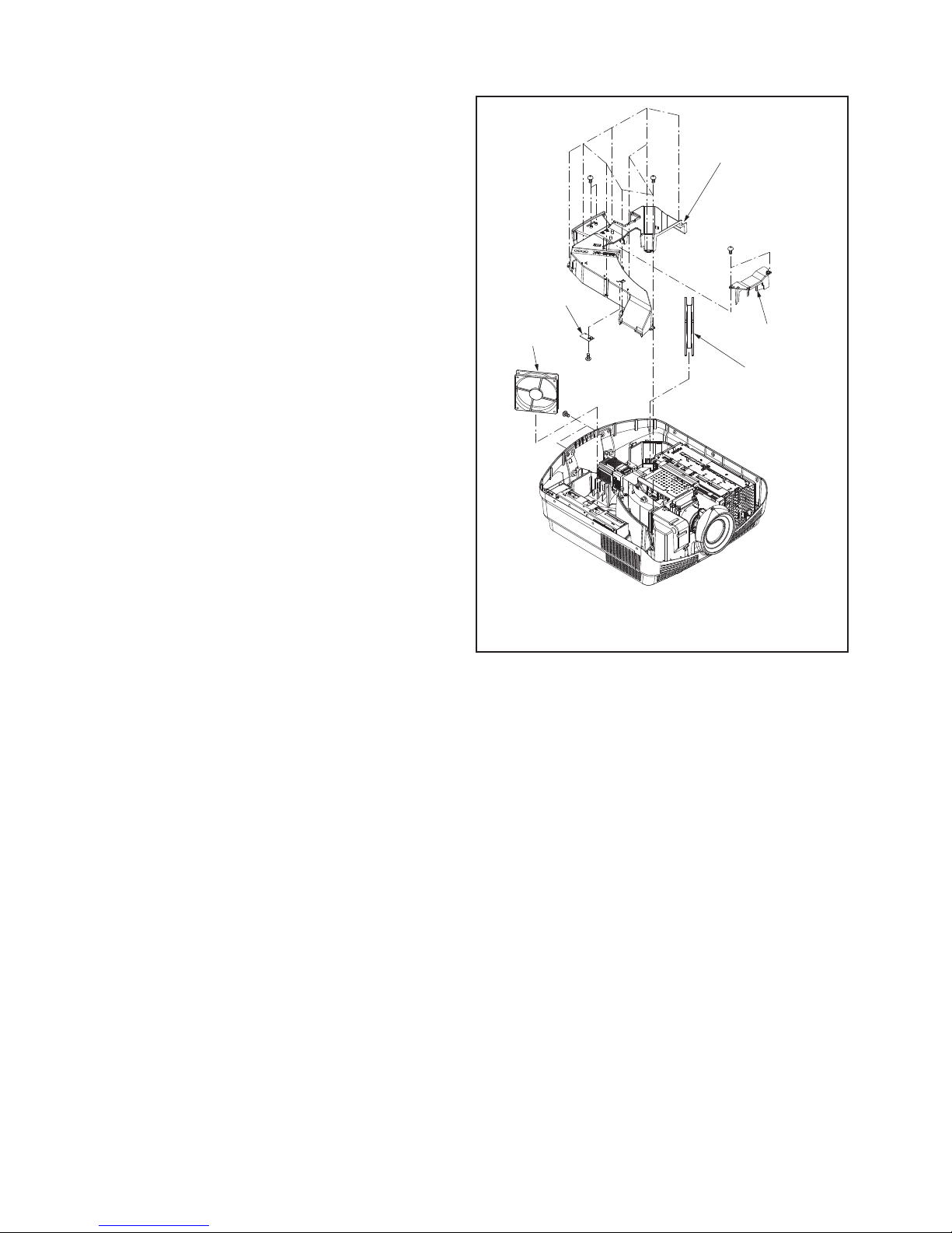
- 16 -
Fig.3-5
11. Removal of the Duct fan (Inlet)
1. Remove the Top cover ASSY according to “1. Removal
of the Top cover ASSY”.
2. Remove the five screws (a) and Duct unit (Inlet) as
shown in Fig. 3-5.
3. Remove the six screws (b) and Duct cover (Inlet) as
shown in Fig. 3-5.
4. Disconnect the connector on the LFT PCB ASSY as
shown in Fig. 3-6.
5. Remove Duct fan (Inlet) as shown in Fig. 3-5.
ax5
bx6
Duct unit (Inlet)
Duct cover
(Inlet)
Duct fan (Inlet)
LEAD DRESS
To remove the Duct cover (Inlet), release the clamper.
- 17 -
Fig.3-6
ax8
bx3
bx3
dx4
ex1
ex1
fx1
fx1
gx2
hx4
bx2
cx2
cx2
HDMI PCB
ASSY
MEMC PCB
ASSY
SCALER PCB ASSY
Memc/Scaler shield
plate ASSY
Scaler shield plate 2
Scaler shield plate 1
LFT PCB
ASSY
12. Removal of the LFT PCB ASSY
1. Remove the Top cover ASSY according to “1. Removal
of the Top cover ASSY”.
2. Remove the eight screws (a) and Memc/Scaler shield
plate ASSY as shown in Fig. 3-6.
3. Remove the eight screws (b) and Scaler shield plate 1
as shown in Fig. 3-6.
4. Remove the four screws (c) and Scaler shield plate 2 as
shown in Fig. 3-6.
5. Disconnect all connectors on the LFT PCB ASSY as
shown in Fig. 3-6.
6. Remove the four screws (d) and LFT PCB ASSY as
shown in Fig. 3-6.
13. Removal of the MEMC PCB ASSY
1. Remove the Top cover ASSY according to “1. Removal
of the Top cover ASSY”.
2. Remove the Memc/Scaler shield plate ASSY according
to “12. Removal of the LFT PCB ASSY”.
3. Disconnect all connectors on the MEMC PCB ASSY as
shown in Fig. 3-6.
4. Remove the two screws (e) and MEMC PCB ASSY as
shown in Fig. 3-6.
14. Removal of the SCALER PCB
ASSY / HDMI PCB ASSY
1. Remove the Top cover ASSY according to “1. Removal
of the Top cover ASSY”.
2. Remove the Memc/Scaler shield plate ASSY according
to “12. Removal of the LFT PCB ASSY”.
3. Disconnect all connectors on the SCALER PCB ASSY
as shown in Fig. 3-6.
4. Remove the two screws (f) and SCALER PCB ASSY as
shown in Fig. 3-6.
5. Disconnect the connectors on the HDMI PCB ASSY as
shown in Fig. 3-6.
6. Remove the two screws (g), four screws (h) and HDMI
PCB ASSY as shown in Fig. 3-6.
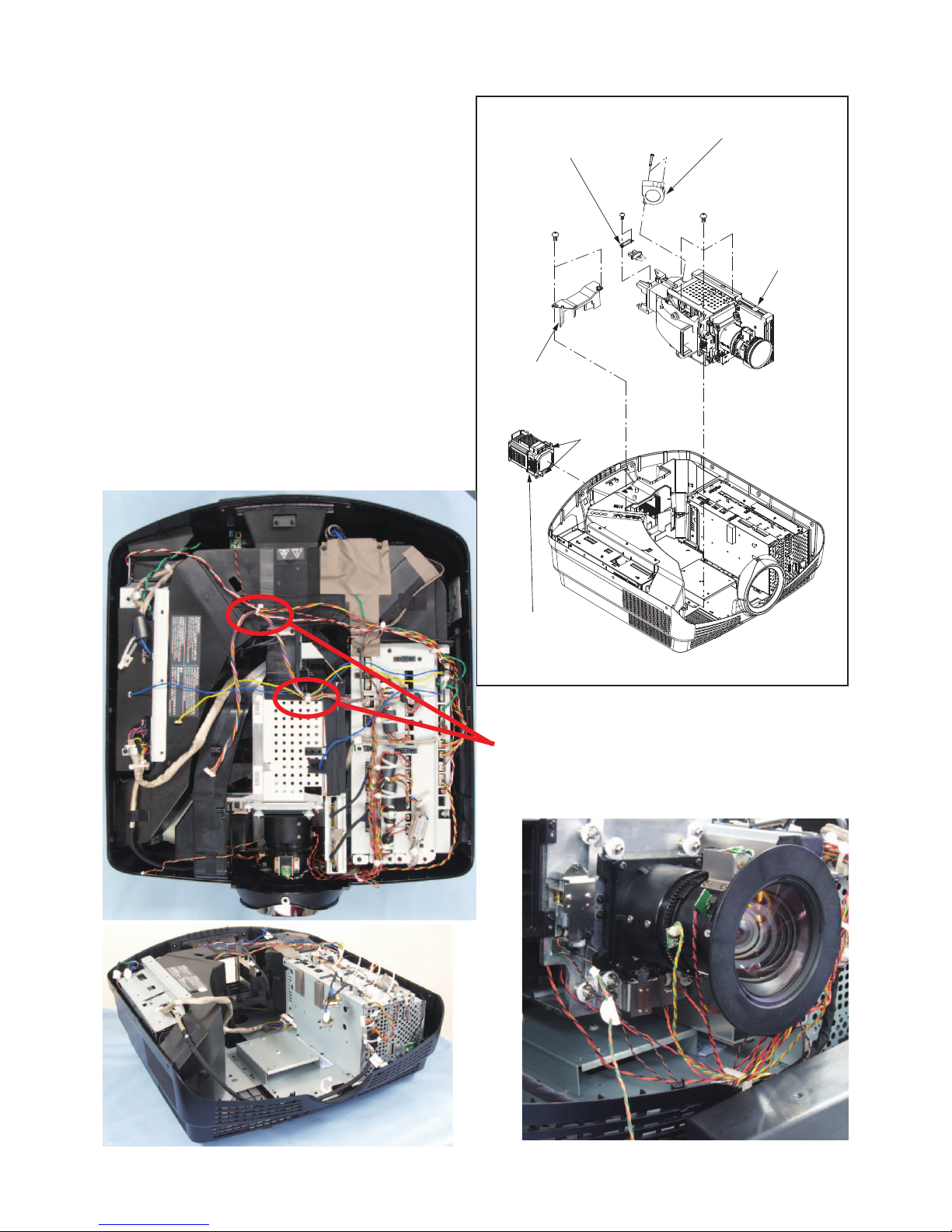
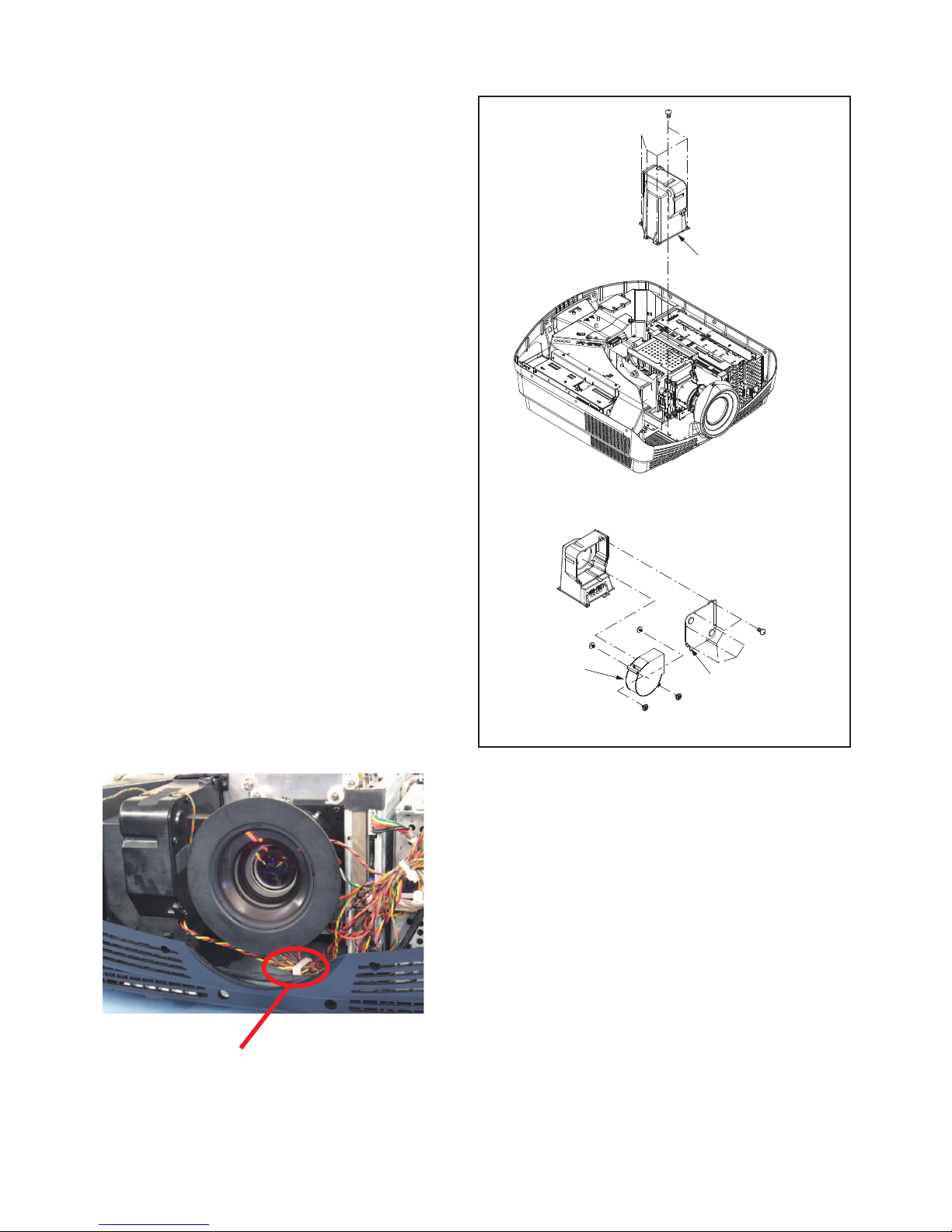
- 18 -
15. Removal of the Lamp unit /
Optical unit / Cooling fan (optical)
1. Remove the Top cover ASSY according to “1. Removal
of the Top cover ASSY”.
2. Remove the Lamp power ASSY according to “6.
Removal of the LAMP POWER PCB ASSY”.
3. Remove the Duct unit (Inlet) according to “11. Removal
of the Duct fan (Inlet) ”.
4. Loose the two screws (a) and remove the Lamp unit as
shown in Fig. 3-7.
5. Remove the two screws (b) and Optical cover as shown
in Fig. 3-7.
6. Remove the two screws (e) , plate and lead wire as
shown in Fig. 3-7.
7. Disconnect all connectors on the Optical unit as shown
in Fig. 3-7.
8. Remove the three screws (c) and Optical unit as shown
in Fig. 3-7.
9. Remove the two screws (d) and Cooling fan (optical) as
shown in Fig. 3-7.
Fig.3-7
ax2
bx2
cx3
dx2
ex2
Cooling fan
(optical)
Optical cover
Lamp unit
Optical unit
Plate
To remove the Optical unit, cut the clamper.
LEAD DRESS
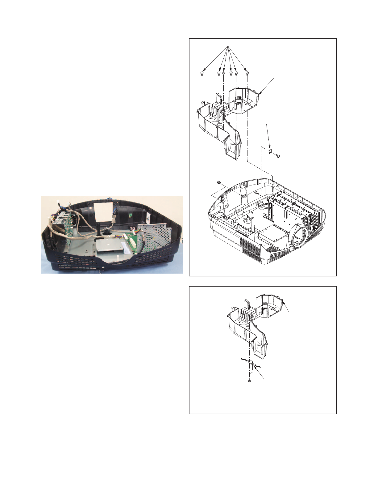
- 19 -
16. Removal of the IR PCB ASSY (REAR)
1. Remove the Top cover ASSY according to “1. Removal
of the Top cover ASSY”.
2. Remove the Power shield plate 1 according to “5.
Removal of the TEMP SENSOR PCB ASSY (POWER)”.
3. Remove the Lamp power ASSY according to “6.
Removal of the LAMP POWER PCB ASSY”.
4. Remove the Top duct ASSY according to “7. Removal of
the TEMP SENSOR PCB ASSY (OUTLET)”.
5. Remove the Duct unit (Inlet) according to “11. Removal
of the Duct fan (Inlet) ”.
6. Remove the Duct unit (Inlet) according to “15. Removal
of the Lamp unit / Optical unit / Cooling fan (optical)”.
7. Remove the six screws (a), two screws (b) and Bottom
duct ASSY as shown in Fig. 3-8.
8. Disconnect the connector on the IR PCB ASSY (REAR)
as shown in Fig. 3-8.
9. Remove the screw (c) and IR PCB ASSY (REAR) as
shown in Fig. 3-8.
17. Removal of the Thermostat
1. Remove the Top cover ASSY according to “1. Removal
of the Top cover ASSY”.
2. Remove the Power shield plate 1 according to “5.
Removal of the TEMP SENSOR PCB ASSY (POWER)”.
3. Remove the Lamp power ASSY according to “6.
Removal of the LAMP POWER PCB ASSY”.
4. Remove the Top duct ASSY according to “7. Removal of
the TEMP SENSOR PCB ASSY (OUTLET)”.
5. Remove the Duct unit (Inlet) according to “11. Removal
of the Duct fan (Inlet) ”.
6. Remove the Optical unit parts according to “15. Removal
of the Lamp unit / Optical unit / Cooling fan (optical)”.
7. Remove the Bottom duct ASSY according to “
16.
Removal of the IR PCB ASSY (REAR)
”.
8. Disconnect the connector on the
Thermostat
as shown in
Fig. 3-9.
9. Remove the two screws (a) as shown in Fig. 3-9.
Fig.3-8
ax6
cx1
bx2
IR PCB
ASSY (REAR)
Bottom duct ASSY
ax2
Bottom duct ASS
Y
Thermostat
Fig.3-9
LEAD DRESS
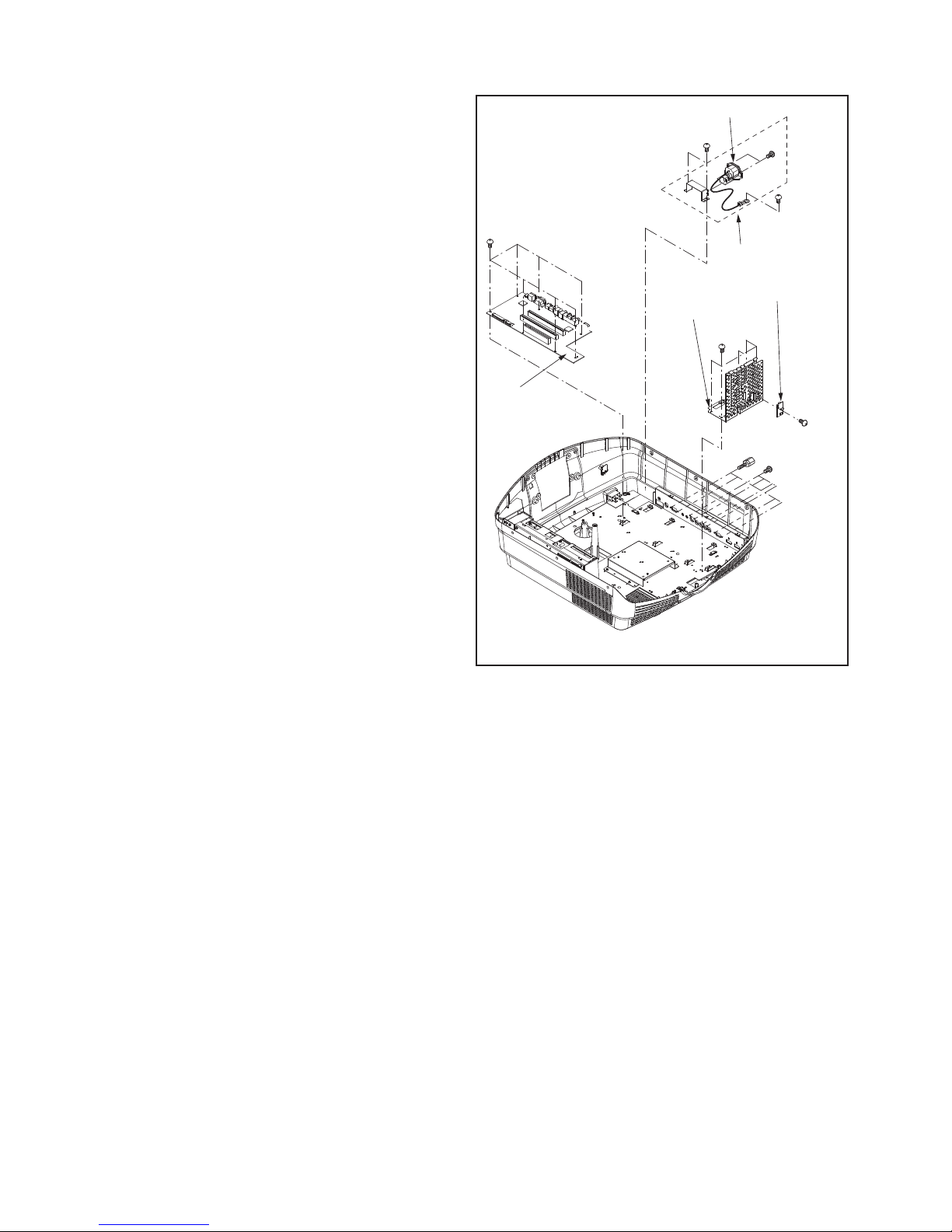
- 20 -
ax4
bx4
cx7
dx5
ex1
gx2
hx1
fx2
AC inlet
AC inlet ASSY
HDMI shield
plate
I/O PCB ASSY
TEMP SENSOR PCB
ASSY (INLET)
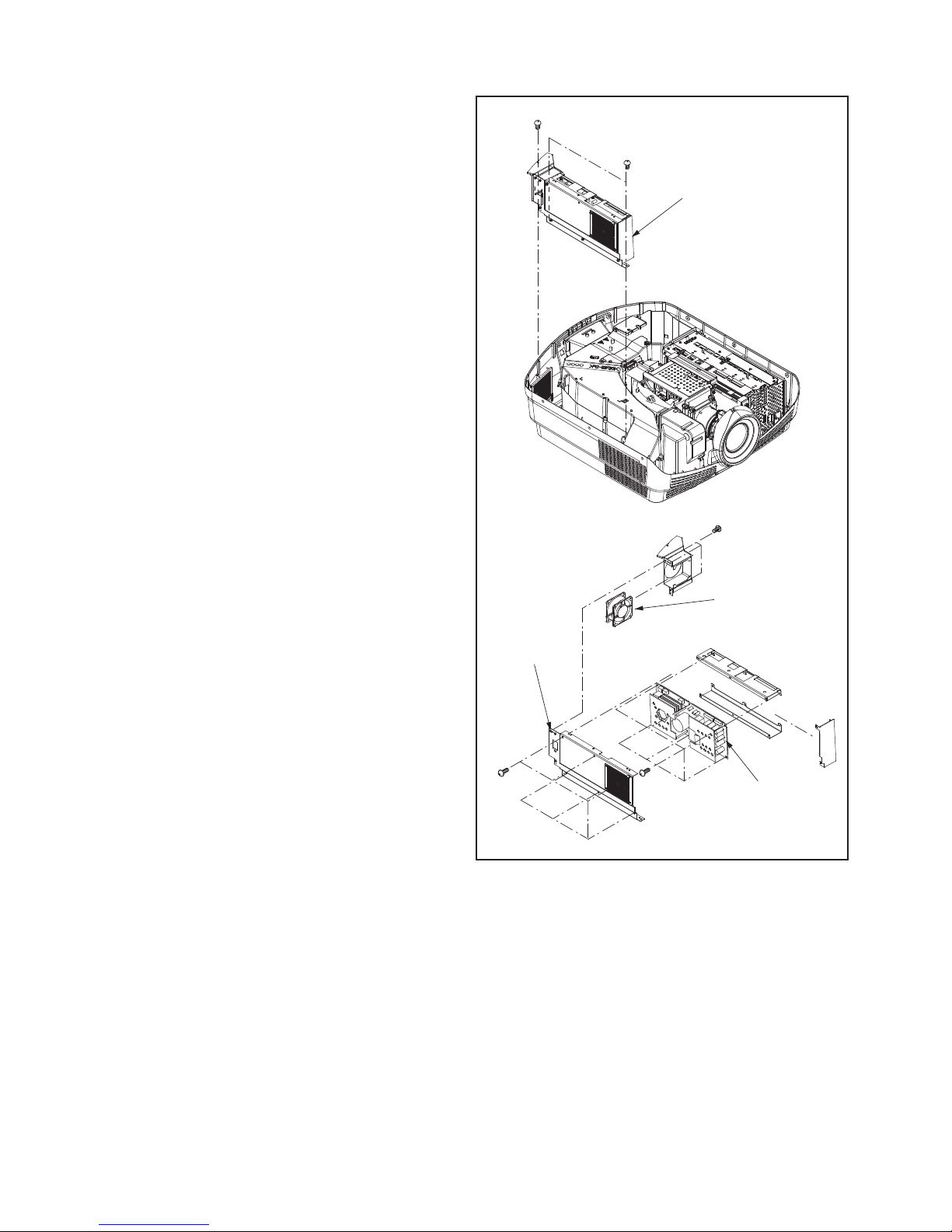
18. Removal of the I/O PCB ASSY /
TEMP SENSOR PCB ASSY (INLET)
1. Remove the Top cover ASSY according to “1. Removal
of the Top cover ASSY”.
2. Remove the Power shield plate 1 according to “5.
Removal of the TEMP SENSOR PCB ASSY (POWER)”.
3. Remove the Lamp power ASSY according to “6.
Removal of the LAMP POWER PCB ASSY”.
4. Remove the Top duct ASSY according to “7. Removal of
the TEMP SENSOR PCB ASSY (OUTLET)”.
5. Remove the Duct unit (Inlet) according to “11. Removal
of the Duct fan (Inlet) ”.
6. Remove the Memc/Scaler shield plate ASSY according
to “12. Removal of the LFT PCB ASSY”.
7. Remove the MEMC PCB ASSY according to “13.
Removal of the MEMC PCB ASSY”.
8. Remove the SCALER PCB ASSY, HDMI PCB ASSY
according to “14. Removal of the SCALER PCB ASSY/
HDMI PCB ASSY”.
9. Remove the optical parts according to “15. Removal of
the Lamp unit / Optical unit/Cooling fan(optical)”.
10. Remove the Bottom duct ASSY according to “16.
Removal of the IR PCB ASSY (REAR)”.
11. Remove the four screws (a), four screws (b), seven
screws (c) and HDMI PCB ASSY as shown in Fig. 3-10.
12. Remove the five screws (d) and HDMI shield plate as
shown in Fig. 3-10.
13. Disconnect the connector on the TEMP SENSOR PCB
ASSY (INLET) as shown in Fig. 3-10.
14. Remove the screw (e) and TEMP SENSOR PCB ASSY
(INLET) as shown in Fig. 3-10.
19. Removal of the AC inlet
1. Remove the Top cover ASSY according to “1. Removal
of the Top cover ASSY”.
2. Remove the Power shield plate 1 according to “5.
Removal of the TEMP SENSOR PCB ASSY (POWER)”.
3. Remove the Lamp power ASSY according to “6.
Removal of the LAMP POWER PCB ASSY”.
4. Remove the Top duct ASSY according to “7. Removal of
the TEMP SENSOR PCB ASSY (OUTLET)”.
5. Remove the Duct unit (Inlet) according to “11. Removal
of the Duct fan (Inlet) ”.
6. Remove the Optical parts according to “15. Removal of
the Lamp unit / Optical unit/Cooling fan(optical)”.
7. Remove the Bottom duct ASSY according to “16.
Removal of the IR PCB ASSY (REAR)”.
8. Remove the I/O PCB ASSY according to “18. Removal
of the I/O PCB ASSY / TEMP SENSOR PCB ASSY
(INLET)”.
9. Remove the two screws (d), screw (e), two screws (f)
and AC inlet as shown in Fig. 3-10.
Fig.3-10
- 21 -
Note : The inner wires are clamped so that they do not come close to heat generating or high voltage parts. After
servicingroute all wires in their original position.
Note : On the lead connector, the connector name isn't indicated. When disconnecting the lead connector, place
labels (
INDEX LABELs
) bearing the reference markings (connector names) near the lead connectors and the
connectors on the board to prevent wrong disconnection. After re-connecting the lead connectors, remove
the labels (
INDEX LABELs
) . To disassemble the product, it is required to cut the BAND KMs that clamp the lead
connectors. Therefore, when re-assembling the product, prepare and use the specified BAND KMs. For the part
number of the BAND KM, refer to PARTS LIST.
For the reference markings of the lead connectors, see pages D23 to D26.
For the connector names of the fans and motors, see pages D35 to D48.
LEAD DRESS
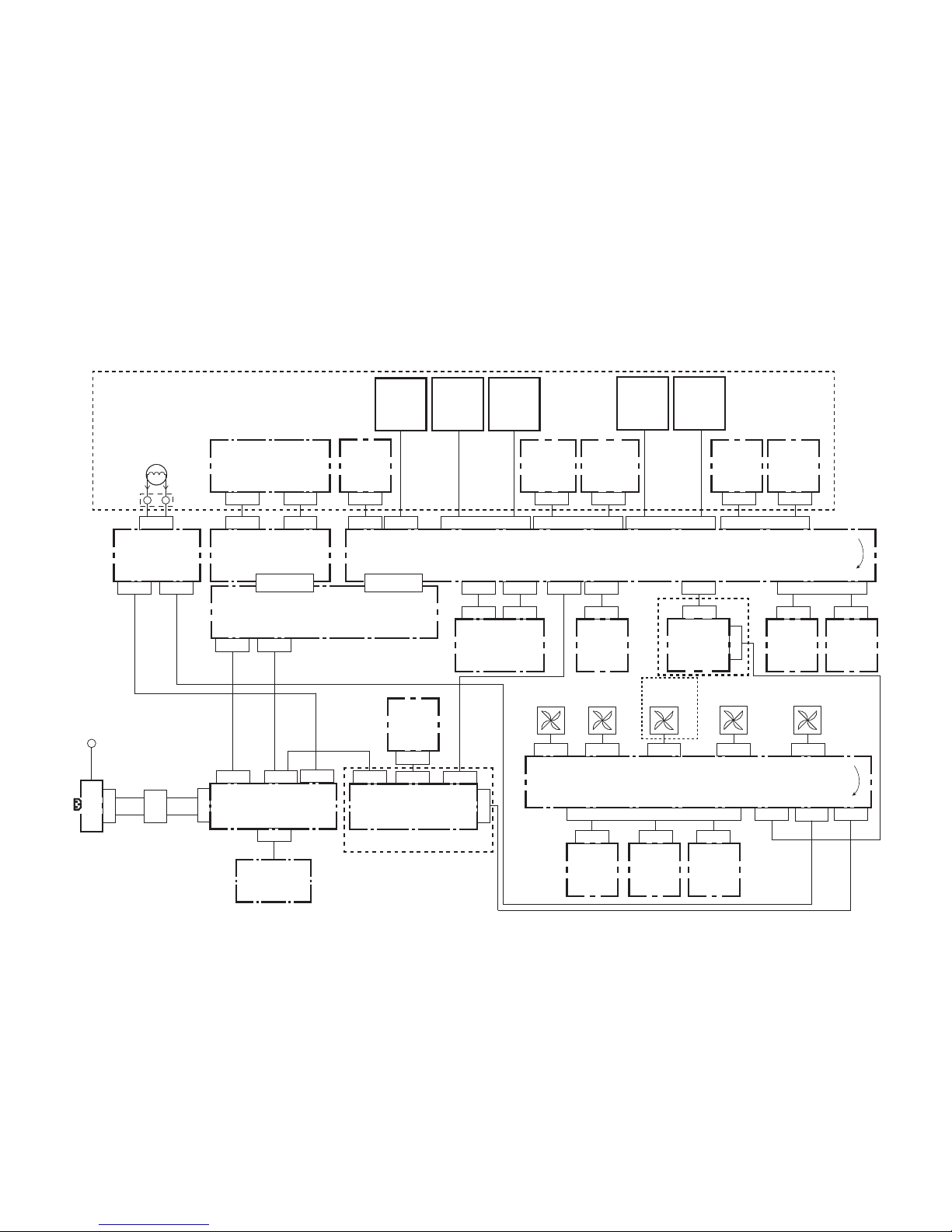
Top view
LFT PCB ASSY
SCALER PCB ASSY
MEMC PCB ASSY
Y-pro PCB ASSY
DDB PCB ASSY
LAMP POWER PCB ASSY
POWER PCB ASSY
HDMI PCB ASSY
I/O PCB ASSY
MEMC SOCKET
SCALER SOCKE
- 22 -
ZZ-3
ZZ-50 ZZ-49
ZZ-18
ZZ-48
ZZ-26 ZZ-24
ZZ-25
ZZ-100 ZZ-101
ZZ-33
ZZ-47
ZZ-54
ZZ-46
ZZ-43
ZZ-102
ZZ-104ZZ-103
ZZ-27
ZZ-23
ZZ-37
ZZ-38
ZZ-51
ZZ-29
ZZ-40ZZ-42
ZZ-300
ZZ-34
ZZ-55
ZZ-39
ZZ-41
ZZ-13
ZZ-53 ZZ-52
ZZ-32
ZZ-19
ZZ-31 ZZ-30
KEY
SWITCH
PCB
ASSY
IR PCB
ASSY
(FRONT)
TEMP
SENSOR
PCB ASSY
(INLET)
TEMP
SENSOR
PCB ASSY
(OUTLET)
TEMP
SENSOR
PCB ASSY
(POWER)
LAMP
COVER
PCB ASSY
IR PCB
ASSY
(REAR)
HORIZONTAL
SHIFT
MOTOR
VERTICAL
SHIFT
MOTOR
ZZ-202
ZOOM
MOTOR
FOCUS
MOTOR
ZZ-201
ZZ-16
VERTICAL
ROTARY
ENCODER
PCB ASSY
SCALER PCB ASSY
MEMC PCB ASSY
LAMP POWER
PCB ASSY
Y-pro PCB ASSY
I/O PCB ASSY
LFT PCB ASSY
DDB PCB ASSY
POWER PCB ASSY
HDMI PCB ASSY
DUCT FAN
(INLET)
POWER
FAN
COOLING
FAN
FAN
(INLET)
FAN
(OUTLET)
ZZ-17
HORIZONTAL
ROTARY
ENCODER
PCB ASSY
ZZ-15
THERMOSTAT
ZZ-14
IRIS1
MOTOR
PCB ASSY
ZZ-2
ZZ-7
ZZ-21
ZOOM
PI SENSOR
PCB ASSY
ZZ-22
FOCUS
PI SENSOR
PCB ASSY
ZZ-20
ZZ-28
ZZ-200
FILTER
MOTOR
ZZ-11
ZZ-12
FILTER
SENSOR
ASSY
ZZ-4
ZZ-9 ZZ-10
ZZ-44
ZZ-45
ZZ-6
ZZ-5
power
switch
AC
inlet
ZZ-301
Chassis
GND
ZZ-35
ZZ-36
ZZ-1
ZZ-8
*1
*1
*1
*1
SOCKT
LAMP
Connection diagram
ZZ-○○○○ : Reference number of the lead connector, not the connector name on the board.
*1 : Optical unit section
- 23 -
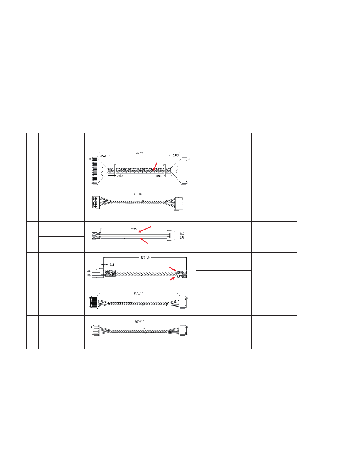
LEAD CONNECTOR
No.
Reference number for
connector insertion
Lead connector
Reference number for
connector insertion
Page describing the
connection
1
SCALER PCB ASSY : (6)
[ZZ-1]
DDB PCB ASSY : (6)
(OPTICAL UNIT)
[ZZ-2]
35
2
SCALER PCB ASSY : (10)
[ZZ-3]
DDB PCB ASSY : (5)
(OPTICAL UNIT)
[ZZ-4]
39
power switch-1
[ZZ-5]
power switch-2
[ZZ-6]
THERMOSTAT
[ZZ-9]
THERMOSTAT
[ZZ-10]
5
SCALER PCB ASSY : (1)
[ZZ-11]
FILTER SENSOR ASSY
(OPTICAL UNIT)
[ZZ-12]
37
6
SCALER PCB ASSY : (8)
[ZZ-13]
IRIS1 MOTOR PCB ASSY
(OPTICAL UNIT)
[ZZ-14]
39
32
32
AC INLET PCB ASSY-1
[ZZ-7]
POWER PCB ASSY : (2)
[ZZ-8]
3
4
Green
Black
Red
Black
Orange / Red / Brown / Black / open
Orange / RedBrown / Black
Yellow /Yellow / Black / Orange / Red /
Black / o
p
en
Brown
 Loading...