

Mitsubishi GT2715XTBA, GT2715-XTBD, GT2712-STWD, GT2712-STBD, GT2712-STBA Installation Manual
...
GOT2000 Series Operator Terminals
Human-Machine Interfaces
Installation Manual for GT2715XTBA, GT2715-XTBD, GT2712-STBA, GT2712-STBD, GT2712-STWA and GT2712-STWD
Art. no.: 280288 ENG, Version A, 29092014
Safety Information
For qualified staff only
This manual is only intended for use by properly trained and qualified electrical technicians who are fully acquainted with automation technology safety
standards. All work with the hardware described, including system design,
installation, setup, maintenance, service and testing, may only be performed
by trained electrical technicians with approved qualifications who are fully
acquainted with the applicable automation technology safety standards and
regulations.
Proper use of equipment
The GOT2000 series operator terminals (GT2715, GT2712) are only intended
for the specific applications explicitly described i n this manual or other manuals. Please take care to observe all the installation and operating parameters
specified in the manual. All products are designed, manufactured, tested and
documented in agreement with the safety regulations. Any modification of
the hardware or software or disregarding of the safety warnings given in this
manual or printed on the product can cause injury to persons or damage to
equipment or other property. Only accessories and peripherals specifically
approved by MITSUBISHI ELECTRIC may be used. Any other use or application
of the products is deemed to be improper.
Relevant safety regulations
All safety and accident prevention regulations relevant to your specific application must be observed in the system design, installation, setup, maintenance, servicing and testing of these products.
In this manual special warnings that are important for the proper and safe use
of the products are clearly identified as follows:
DANGER:
Personnel health and injury warnings.
Failure to observe the precautions described here can result
P
in serious health and injury hazards.
CAUTION:
Equipment and property damage warnings.
Failure to observe the precautions described here can result
E
in serious damage to the equipment or other property.
Further Information
More information about the operator terminals of the GO T2000 series and the
configuration tool MELSOFT GT Works3 is available free of charge through the
internet (https://eu3a.mitsubishielectric.com).
If you have any questions concerning the installation, configuration or operation of the equipment described in this manual, please contact your relevant
sales office or department.
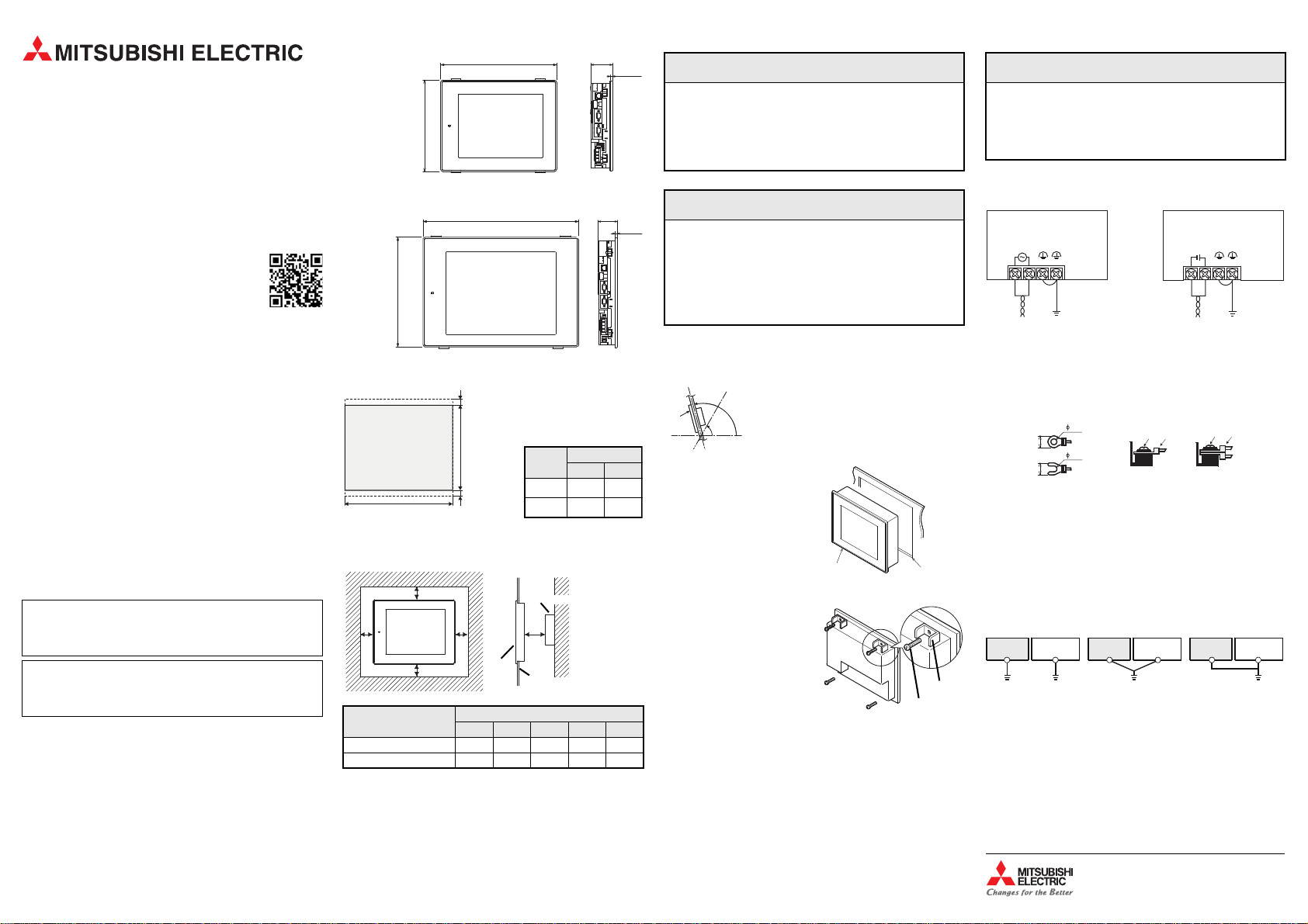
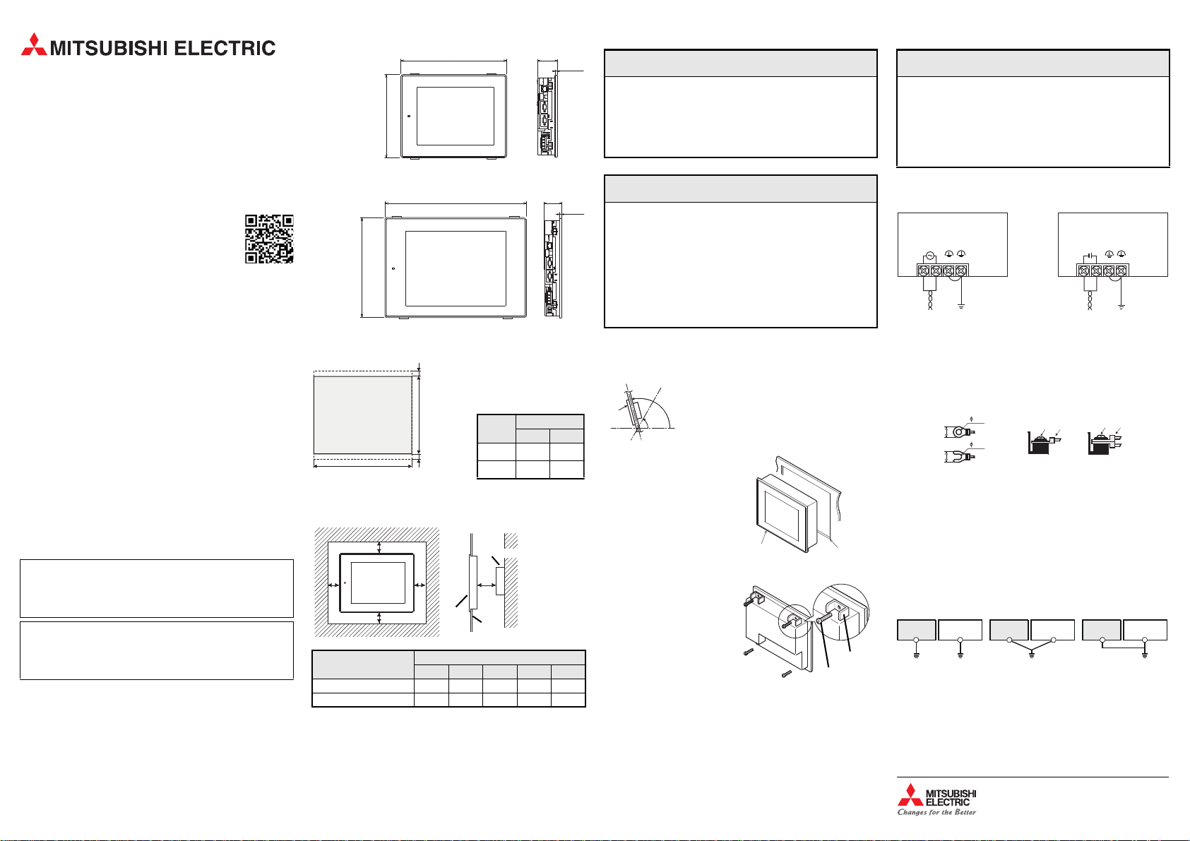
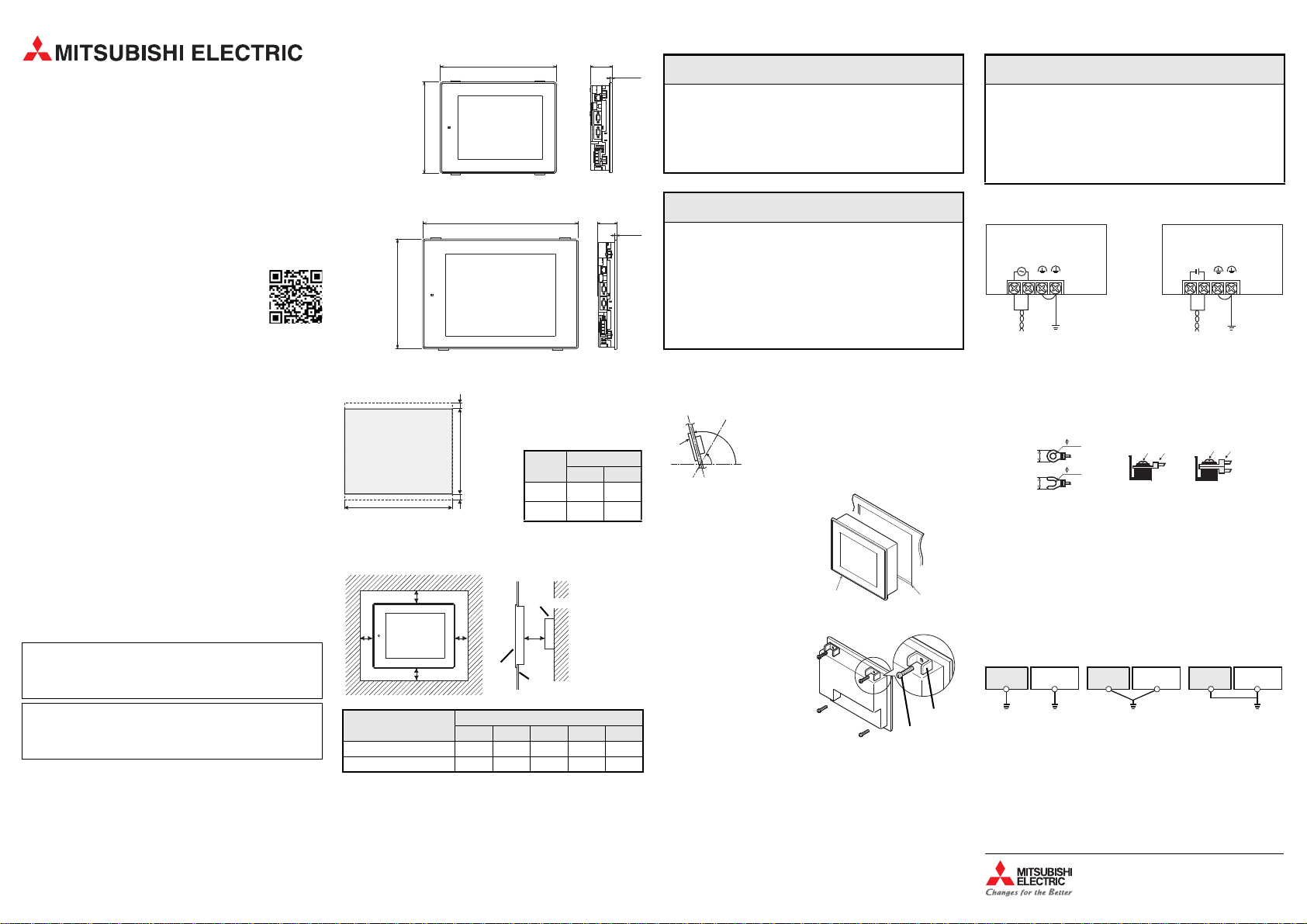
Dimensions
GT2715
300
All dimensions are in „mm“.
GT2712
246
All dimensions are in „mm“.
Panel Cut Out
Unit: mm
A
10 or more
B
10 or more
397
316
A space of at least 10 mm at
the upper and lower side of
the GOT is required to allow for
the attachment of mounting
fixtures.
GOT
GT2715
GT2712
Distances to other devices
When mounting the GOT, please maintain the following clearances from other
devices.
B
C
A
* Panel thickness: 2.0 to 4.0 mm
Distances to other
devices
SD card not used 48 (20) 78 (18) 50 (20) 50 (20) 100 (20)
SD card used 48 (20) 78 (18) 50 50 (20) 100 (20)
The values enclosed in parenthesis apply to the case where no other equipment generating radiated noise (such as a contactor) or heat is installed
nearby.
D
GOT
A B C D E
Other device
E
Panel*
Minimum clearances [mm]
60
6
52
Cut Out [mm]
A B
383.5+2282.5
–0–0–0
302+2228
6
+2
+2
–0
Installation and Wiring
P
● Switch OFF the power supply of the operator terminal before starting
the installation work or wiring and before mounting or removing the
option function board.
● When the communication between the operation terminal and the
PLC fails it is impossible to operate keys or devices via the operation
terminal. Therefore emergency stops and other safety functions must
not be controlled via the PLC.
E
● Do not disassemble or modify the unit. Doing so can cause a failure,
malfunction, injury or fire.
● Use the GOT in the environment that satisfies the general specifications described in this manual. Don't mount the operation terminal in
an enviroment that contains high explosive risks, strong magnetic
fields, direct sunlight or large, sudden temperature changes.
● Never allow fluids, metal filings or wiring debris to enter any openings
in the operator terminal. This may cause short circuits and fire.
Mounting
A GOT is designed to be installed into the door of a control cabinet or into a
control panel.
GOT
햲 Prepare a hole in the panel with the dimensions shown on the left.
햳 Insert the GOT from the front of the
panel or the control cabinet into
the cut out.
햴 Place the mounting fittings (sup-
plied) into the provided openings
of the GOT and tighten the screws
until the GOT is fixed. Please use all
four supplied mounting fittings
and tighten the mounting screws
with a torque of 0.36 to 0.48 Nm.
햵 After mounting, remove the protection film from the operator terminal
display.
105°
60°
DANGER
CAUTION
When the temperature inside the control cabinet or
control panel is 40 to 55 °C the mounting angle
should be in the range 60° to 105° degrees.
GOT
Cut out
Magnified illustration
Mounting
fitting
Mounting
screw
Power Supply Wiring
Wiring of one cable to
3.2 mm
3.2 mm
: Terminal screw
: Solderless terminal
GOT
Shared grounding
CAUTION
one terminal
Other
equipment
Good condition
GT2715-XTBD
GT2712-STBD, GT2712-STWD
INPUT
24VDC
-
+
(LG) (FG)
24 V DC
Wiring of two cables to
Grounting
one terminal
GOT
equipment
Common grounding
Not allowed
Other
E
● Do not lay signal cables close to the main circuit, high-voltage power
lines, or load lines. Otherwise effects of noise or surge induction are
likely to take place. Keep a safe distance of more than 100 mm from
the above when wiring.
● When connecting the power supply please confirm the rated voltage
and the polarity. Not doing so can cause a fire or failure.
Connect the power supply to the power terminals on the back panel of the
GOT.
GT2715-XTBA
GT2712-STBA, GT2712-STWA
INPUT
100-240VAC
(LG) (FG)
Other
equipment
Grounting
100 to 240 V AC
Use the thickest cable possible (max. 2 mm2) to minimize the voltage drop and
start twisting them close to the connection terminals. Tighten the terminal
screws securely with a torque of 0.5 to 0.8 Nm.
Use commercially available terminal ends for M3 screws for connection of the
power supply (see figure below).
6.2 mm
or less
6.2 mm
or less
Grounding
Ground the GOT using the ground terminal at the lower left corner of the operator terminal (Refer to the figure at the top of this column).
● The grounding resistance should be 100 액 or less.
● The grounding point should be close to the GOT. Keep the grounding wires
as short as possible.
● The ground wire size should be at least 2 mm2.
● Independent grounding should be performed for best results. When inde-
pendent grounding is not performed, perform "shared grounding" of the
following figure.
GOT
Independent grounding
Best condition
Connection to the Control System
An operator panel of the GOT2000 series can be connected not only to PLCs
from Mitsubishi Electric but also to inverters, servo ampli fiers, CNC as well and
to PLCs from third party manufacturers and many other devices. For further
information please refer to t he Connection Manual for the GOT2000 series.
Mitsubishi Electric Europe B.V. / // FA - European Business Group ///
Germany /// Tel.: +49(0)2102-4860 /// Fax: +49(0)2102-4861120 ///
https://eu3a.mitsu bishielectric.com
Abmessungen
Alle Abmessungen sind in der Einheit „mm“ angegeben.
60
300
397
6
GT2715
Alle Abmessungen sind in der Einheit „mm“ angegeben.
52
246
316
6
GT2712
An der Ober- und Unterseite
des GOT ist ein freier Raum
von mindestens 10 mm für die
Befestigungselemente erforderlich.
GOT
Ausschnitt [mm]
A B
GT2715
383,5+2282,5
+2
GT2712
302+2228
+2
욷10
욷10
Einheit: mm
A
B
–0–0–0
–0
B
D
GOT
z. B. Schaltschranktür*
A
C
E
Anderes Gerät
105°
60°
GOT
Beträgt die Temperatur im Schaltschrank oder Pult
40 bis 55 °C muss das GOT in einem Winkel von 60°
bis 105° montiert werden.
GOT
Ausschnitt
Vergrößerte Darstellung
Befestigungsschraube
Befestigungselement
(LG) (FG)
(LG) (FG)
INPUT
100-240VAC
INPUT
24VDC
+
-
GT2715-XTBA
GT2712-STBA, GT2712-STWA
GT2715-XTBD
GT2712-STBD, GT2712-STWD
100 bis 240 V AC
Erdung
24 V DC
Erdung
Eine Leitung an
einer Klemme
Zwei Leitungen an
einer Klemme
: Klemmenschraube
: Ringöse oder Kabelschuh
3,2 mm
3,2 mm
max. 6,2 mm
max. 6,2 mm
GOT
GOT
GOT
Sonstige
Geräte
Sonstige
Geräte
Sonstige
Geräte
Unabhängige Erdung
Beste Lösung
Gemeinsame Erdung
Gute Lösung
Gemeinsame Erdung
Nicht zulässig!
Installation und Verdrahtung
Anschluss der Versorgungsspannung
Bediengeräte der GOT2000-Serie
Mensch-Maschine-Interface
Installationsanleitung für
GT2715XTBA, GT2715-XTBD,
GT2712-STBA, GT2712-STBD,
GT2712-STWA und GT2712-STWD
Art. Nr.: 280288 GER, Version A, 29092014
Sicherheitshinweise
Nur für qualifizierte Elektrofachkräfte
Diese Installationsanleitung richtet sich ausschließlich an anerkannt ausgebildete Elektrofachkräfte, die mit den Sicherheitsstandards der Elektro- und
Automatisierungstechnik vertraut sind.
Projektierung, Installation, Inbetriebnahme, Wartung und Prüfung der Geräte
dürfen nur von einer anerkannt ausgebildeten Elektrofachkraft durchgeführt
werden. Eingriffe in die Hard- und Software unserer Produkte, soweit sie nicht
in dieser Installationsanleitung oder anderen Handbüchern beschrieben sind,
dürfen nur durch unser Fachpersonal vorgenommen werden.
Bestimmungsgemäßer Gebrauch
Die grafischen Bediengeräte der GOT2000-Serie (GT2 715, GT2712) sind nur für
die Einsatzbereiche vorgesehen, die in der vorliegenden Installationsanleitung oder anderen Handbüchern beschrieben sind.
Achten Sie auf die Einhaltung der in den Handbüchern angegebenen allgemeinen Betriebsbedingungen. Die Produkte wurden unter Beachtung der
Sicherheitsnormen entwickelt, gefertigt, geprüft und dokumentiert. Unqualifizierte Eingriffe in die Hard- oder Software bzw. Nichtbeachtung der in dieser
Installationsanleitung angegebenen oder am Produkt angebrachten Warnhinweise können zu schweren Personen- oder Sachschäden führen.
Es dürfen nur von MITSUBISHI ELECTRIC empfohlene Zusatz- bzw. Erweiterungsgeräte verwendet werden. Jede andere darüber hinaus gehende Verwendung oder Benutzung gilt als nicht bestimmungsgemäß.
Sicherheitsrelevante Vorschriften
Bei der Projektierung, Installation, Inbetriebnahme, Wartung und Prüfung der
Geräte müssen die für den spezifischen Einsatzfall gültigen Sicherheits- und
Unfallverhütungsvorschriften beachtet werden.
In dieser Installationsanleitung befinden sich Hinweise, die für den sachgerechten und sicheren Umgang mit dem Gerät wichtig sind. Die einzelnen Hinweise haben folgende Bedeutung:
GEFAHR:
Warnung vor einer Gefährdung des Anwenders
Nichtbeachtung der angegebenen Vorsichtsmaßnahmen
P
kann zu einer Gefahr für das Leben oder die Gesundheit des
Anwenders führen.
ACHTUNG:
Warnung vor einer Gefährdung von Geräten
Nichtbeachtung der angegebenen Vorsichtsmaßnahmen
E
kann zu schweren Schäden am Gerät oder anderen Sachwerten führen.
Weitere Informationen
Weitere Informationen zu den Bediengeräten der GOT2000-Serie und der Programmier-Software MELSOFT GT Works3 stehen Ihnen im Internet kostenlos
zur Verfügung (https://de3a.mitsubishielectr ic.com).
Sollten sich Fragen zur Installation, Konfiguration oder Betrieb der Bedien-geräte der GOT2000-Serie ergeben, zögern Sie nicht, Ihr zuständiges Verkaufsbüro oder einen Ihrer Vertriebspartner zu kontaktieren.
P
● Schalten Sie vor der Installation, der Verdrahtung sowie dem Ein- und
Ausbau einer Optionskarte die Versorgungsspannung des Bediengeräts aus.
●
Beachten Sie, dass bei einer Störung der Kommunikation zwischen dem
Bediengerät und der SPS keine Bedienung mehr über das Bedien-gerät
möglich ist. Aus di esem Grund darf die Betätigung der NOT-AUS- und
anderer Sicherheitseinrichtungen nicht über ein Bediengerät erfolgen.
E
●
Öffnen Sie und verändern Sie das Gerät nicht. Dies könnte zu Defekten, Fehlfunktionen, Verletzungen oder Bränden führen.
●
Betreiben Sie das GOT nur in einer Umgebung, in der die in dieser Installationsanleitung angegebenen Umgebungsbedingungen eingehalten
werden. Installieren Sie die Bediengeräte nicht in einer Umgebung, in
der Explosionsgefahr herrscht oder in der sie starken magnetischen
Feldern, direkter Sonneneinstrahlung oder großen und plötzlichen
Temperaturschwankungen ausgesetzt sind.
●
Es dürfen keine Flüssigkeiten, Bohrspäne oder Drahtreste durch die
Öffnungen in die Bediengeräte eindringen. Dies könnte einen Kurzschluss und dadurch Brände verursachen.
Schalttafelausschnitt
Abstände zu anderen Geräten
Bitte halten Sie bei der Montage des GOT die folgenden Abstände zu anderen
Geräten ein.
* Wanddicke: 2,0 bis 4,0 mm
Abstände zu anderen
Geräten
CF-Karte nicht verwendet 48 (20) 78 (20) 50 (20) 50 (20) 100 (20)
CF-Karte verwendet 48 (20) 78 (20) 50 50 (20) 100 (20)
Die Werte in Klammern gelten für den Fall, dass in der Nähe des GOT keine Geräte wie z. B. Schütze installiert sind, die elektromagnetische Störungen erzeugen oder die Hitze ausstrahlen.
Minimale Abstände [mm]
A B C D E
Montage
Die GOTs sind für die Montage in einer Schaltschranktür oder einem Schaltpult
vorgesehen.
햲 Fertigen Sie einen Ausschnitt mit den links angegebenen Maßen.
햳 Führen Sie das Bediengerät von der
Vorderseite des Schaltschrankes
oder Pultes durch den Schalttafelausschnitt.
햴 Haken Sie die mitgelieferten Befes-
tigungselemente in die dafür
vorgesehenen Öffungen des GOT.
Verwenden Sie bitte alle vier Befestigungselemente, und ziehen Sie
die Schrauben mit einem Moment
von 0,36 bis 0,48 Nm an.
햵 Entfernen Sie nach der Montage die Schutzfolie von der Anzeige.
GEFAHR
ACHTUNG
E
●
Verlegen Sie Signalleitungen nicht in der Nähe von Netz- oder Hochspannungsleitungen oder Leitungen, die eine Lastspannung führen.
Der Mindestabstand zu diesen Leitungen beträgt 100 mm. Wenn dies
nicht beachtet wird, können durch Störungen Fehlfunktionen
auftreten.
●
Achten Sie beim Anschluss der Versorgungsspannung auf die Höhe
und die Polarität der Spannung. Wenn dies nicht beachtet wird, können Defekte oder Brände auftreten.
Die Versorgungsspannung wird an den Klemmen an der Rückseite des GOT
angeschlossen.
Verwenden Sie zur Reduzierung des Spannungsabfalls Leitungen mit dem
größt möglichen Querschnitt (max. 2 mm2) und verdrillen Sie die ein-zelnen
Adern bis kurz vor den Anschlussklemmen. Ziehen Sie die Schrauben der
Klemmen mit einem Moment von 0,5 bis 0,8 Nm an .
Zum Anschluss der Versorgungsspannung verwenden Sie bitte handelsübliche Ringösen oder Kabelschuhe für M3-Schrauben (siehe unten).
Erdung
Erden Sie das GOT über den Anschluss in der linken unteren Ecke des Geräts
(siehe Darstellung oben in dieser Spalte).
● Der Erdungswiderstand darf max. 100 액 betragen.
● Der Anschlusspunkt sollte so nah wie möglich am GOT sein. Die Drähte für
die Erdung sollten so kurz wie möglich sein.
● Der Querschnitt der Erdungsleitung sollte mindestens 2 mm2 betragen.
● Das GOT sollte nach Möglichkeit unabhängig von anderen Geräten geer-
det werden. Sollte eine eigenständige Erdung nicht möglich sein, ist eine
gemeinsame Erdung entsprechend dem mittleren Beispiel in der folgenden Abbildung auszuführen.
Anschluss an eine Steuerung
Die grafischen Bediengeräte der GOT2000-Serie können nicht nur an die speicherprogrammierbaren Steuerungen von Mitsubishi Electric angeschlossen
werden, sondern auch an Frequenzumrichter, Servoverstärker und CNC-Steuerungen sowie an SPS von Fremdherstellern und vielen anderen Geräten. Weitere Informationen enthält die Bedienungsanleitung zur GOT2000-Serie
(Anschluss).
ACHTUNG
Mitsubishi Electric Europe B.V. / // FA - European Business Group ///
Germany /// Tel.: +49(0)2102-4860 /// Fax: +49(0)2102-4861120 ///
https://de3a.mitsubishielectric.com
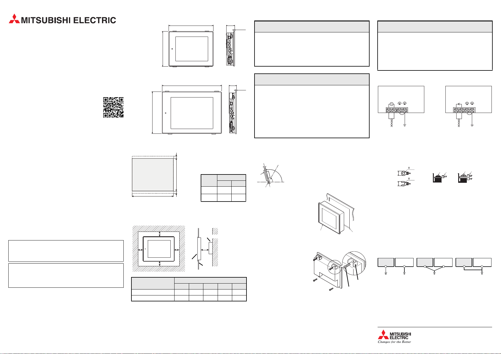
Dimensions
Toutes les dimensions sont en « mm».
60
300
397
6
GT2715
Toutes les dimensions sont en « mm».
52
246
316
6
GT2712
Un espace minimal de 10 mm
au-dessus et au-dessous du
terminal GOT est indispensable pour les fixations.
GOT
Découpe [mm]
A B
GT2715
383,5+2282,5
+2
GT2712
302+2228
+2
욷10
욷10
Unités : mm
A
B
–0–0–0
–0
B
D
GOT
Panneau*
A
C
E
Autre appareil
105°
60°
GOT
Lorsque la température à l’intérieur du coffret de
commande ou tu tableau de commande est comprise entre 40 et 55 °C, l’angle de montage doit être
compris entre 60° et 105°.
GOT
Découpe
Détail
Vis de fixation
Fixation
(LG) (FG)
(LG) (FG)
INPUT
100-240VAC
INPUT
24VDC
+
-
GT2715-XTBA
GT2712-STBA, GT2712-STWA
GT2715-XTBD
GT2712-STBD, GT2712-STWD
100 à 240 V CA
Mise à la terre
24 V CC
Mise à
la terre
Câblage d’un câble sur
une borne
Câblage de deux câbles
sur une borne
: Vis
: Borne sans soudure
3,2 mm
3,2 mm
maxi. 6,2 mm
maxi. 6,2 mm
GOT
GOT
GOT
Appareils
divers
Appareils
divers
Appareils
divers
Mise à la terre
indépendant
La solution la meilleure
Mise à la terre commune
Bonne solution
Mise à la terre commune
Non autorisé!
Installation et câblage
Raccordement de la tension d'alimentation
Pupitres opérateurs de la série GOT2000
Interface homme machine
Manuel d'installation pour GT2715XTBA, GT2715-XTBD, GT2712-STBA, GT2712-STBD, GT2712-STWA et GT2712-STWD
N°. art : 280288 FRA, Version A, 29092014
Informations de sécurité
Groupe cible
Ce manuel est destiné uniquement à des électriciens qualifiés et ayant reçus
une formation reconnue par l'état et qui se sont familiarisés avec les standards
de sécurité de la technique d'automatisation.
Tout travail avec le matériel décrit, y compris la planification, l'installation, la
configuration, la maintenance, l'entretien et les tests doit être réalisé uniquement par des électriciens formés et qui se sont familiarisés avec les standards
et prescriptions de sécurité de la technique d'automatisation applicable.
Utilisation correcte
Les pupitres opérateurs graphiques de la série GOT2000 (GT2715, GT2712)
sont prévus uniquement pour les domaines d'utilisation décrits dans le
manuel d'installation présent ou dans les autres manue ls.
Veuillez prendre soin de respecter tous les paramètres d'installation et de
fonctionnement spécifiés dans le manuel. Tous les produits ont été développés, fabriqués, contrôlés et documentés en respectant les normes de sécurité.
Toute modification du matériel ou du logiciel ou le non-respect des avertissements de sécurité indiqués dans ce manuel ou placés sur le produit peut
induire des dommages importants aux personnes ou au matériel ou à d'autres
biens. Seuls les accessoires et appareils périphériques recommandés par
MITSUBISHI ELECTRIC doivent être utilisés. Tout autre emploi ou application
des produits sera considéré comme non conforme.
Prescriptions de sécurité importantes
Toutes les prescriptions de sécurité et de prévention d'accident importantes
pour votre application spécifique doivent être respectées lors de la planification, l'installation, la configuration, la maintenance, l'entretien et les tests de
ces produits.
Dans ce manuel, les avertissements spéciaux importants pour l'utilisation
correcte et sûre des produits sont indentifiés clairement co mme suit :
DANGER :
Avertissements de dommage corporel.
Le non-respect des précautions décrites ici peut entraîner
P
des dommages corporels et des risques de blessure.
ATTENTION :
Avertissements d'endommagement du matériel et des
biens.
E
Le non-respect des précautions décrites ici peut entraîner de
graves endommagements du matériel ou d'autres biens.
Autres informations
Vous trouverez d'autres informations à télécharger gratuitement sur les pupitres
opérateurs de la série GOT2000 et le logiciel de programmation MELSOFT
GT Works3 sur notre site Internet (https://eu3a.mitsubishielectric.com).
Si vous avez des questions concernant la programmation et le fonctionnement du matériel dé crit dans ce manuel, contactez votre bureau de vente responsable ou votre distributeur.
P
● Coupez l’alimentation du pupitre opérateur avant l’installation ou le
câblage et avant le montage ou le démontage de la carte optionnelle.
● Tenez compte du fait que lors d'une défaillance de la communication
entre le pupitre opérateur et l'API, plus aucune commande via le pupitre opérateur n'est possible. Pour cette raison, l'actionnement du
dispositif d'arręt d'urgence et d'autres dispositifs de sécurité ne doit
pas ętre effectué via un pupitre opérateur.
E
● Ne démontez pas et ne modifiez pas l’appareil, faute de quoi vous pouvez provoquer une panne, un dysfonctionnement, des blessures ou un
incendie.
● Utilisez le terminal GOT dans un environnement conforme aux spécifications indiquées dans ce manuel. N'installez pas les pupitres opérateurs dans un environnement exposé aux explosions ou dans lequel ils
sont exposés à des champs magnétiques importants, à un ensoleillement direct ou des variations de température fortes et soudaines.
● Aucun liquide, aucune alésure ou reste de câble ne doit pénétrer dans
les pupitres opérateurs par les ouvertures. Ceci pourrait provoquer un
court-circuit et donc des incendies.
Découpe du panneau de distribution
Distances des autres appareils
Lors du montage du pupitre GOT, laissez les espaces suivants avec les autres
appareils.
* Épaisseur de la paroi : 2,0 à 4,0 mm
Distances des autres
appareils
Carte CF inutilisée 48 (20) 78 (20) 50 (20) 50 (20) 100 (20)
Carte CF utilisée 48 (20) 78 (20) 50 50 (20) 100 (20)
Les valeurs entre parenthèses concernent le cas où aucun autre appareil rayonnant du bruit électrique (ex. contacteur) ou de la chaleur est installé à proximité.
Espaces minimaux [mm]
A B C D E
Montage
Les pupitres opérateurs GOT sont conçus pour l’intégration dans une armoire
de distribution ou un pupitre de commande.
햲
Préparez un trou dans le tableau aux cotes indiquées à gauche.
햳
Faites passer le pupitre opérateur
par la face avant de l'armoire de distribution ou de l'armoire-pupitre à
travers la découpe du panneau de
distribution.
햴
Engagez le crochet de fixation
(fourni) dans le trou de fixation du
terminal GOT et serrez la vis.
Veuillez utiliser tous les éléments
de fixation et serrer les vis avec un
couple de 0,36 à 0,48 Nm.
햵
Retirez après le montage le film de protection de l'affichage.
DANGER
ATTENTION
E
● Ne pas poser des câbles de signaux à proximité de câbles du secteur et
de câbles à haute tension ou de câbles parcourus par une tension en
décharge. L'écart minimal avec ces câbles est de 100 mm. Des défaillances dues à des perturbations peuvent apparaître si cet écart n'est
pas respecté. Si cela n'est pas respecté, des dysfonctionnements dus à
des défaillances peuvent apparaître.
● Lorsque vous raccordez l’alimentation, vérifiez la tension nominale et
la polarité, faute de quoi vous pouvez provoquer un incendie.
Raccordez l’alimentation aux bornes à l’arrière du terminal GOT.
Utilisez des fils de section maximale 0,2 mm2 pour évit er le s chu tes de tens ion ;
serrez les vis des bornes à un couple compris entre 0,5 et 0,8 Nm.
Veuillez utiliser pour le raccordement de la tension d'alimentation descosses
à œillet ou à fourche pour vis M3 (voir ci-dessous).
Mise à la terre
Raccordez le terminal GOT à la terre à l’aide de la born e située dans le coin inférieur gauche du pupitre opérateur (voir la figure au bas de cette colonne).
●
La résistance de mise à la terre do it être de 100 액 maximum.
●
Le point de raccordement doit être aussi proche que possible de pupitre
opérateur GOT. Les conducteurs pour la mise à la terre doivent être aussi
courts que possible.
●
La section du conducteur de terre doit être de 2 mm2 minimum.
●
Le pupitre opérateur GOT doit si possible être mis à la terre indépendamment des autres appareils. Si une mise à la terre indépendante n'est pas
possible, une mise à la terre commune doit être réalisée selon l'exemple du
milieu de la figure suivante.
Connexion au circuit de commande
Vous pouvez connecter les tableaux de commande GOT2000 non seulement
à des automates programmables Mitsubishi Electric, maiségalement à des
variateurs, des servo-amplificateurs, des contrôleurs de commande numérique, ainsi qu’à des automates programmables et à des appareils d’autres
fabricants. Pour en savoir plus, voir le Manuel de connexion de la Série
GOT2000.
ATTENTION
Mitsubishi Electric Europe B.V. / // FA - European Business Group ///
Germany /// Tel.: +49(0)2102-4860 /// Fax: +49(0)2102-4861120 ///
https://eu3a.mitsu bishielectric.com
GT2715-XTBA/-XTBD
GT2712-STBA/-STWA, GT2712-STBD/-STWD
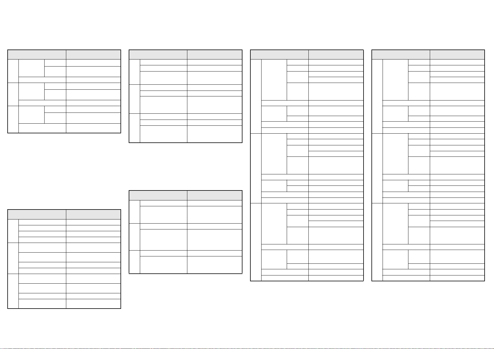
General Specifications
m
Umgebungsbedingungen
D
Conditions générales de service
F
GT2715-XTBA
GT2712-STBA/-STWA
Power Supply Specifications
m
Spannungsversorgung
D
Alimentation en courant
F
GT2715-XTBA/
GT2715-XTBD
Specifications
m
Technische Daten
D
Caractéristiques techniques
F
GT2712-STBA/-STWA/
GT2712-STBD/-STWD
Specifications
m
Technische Daten
D
Caractéristiques techniques
F
Item / Merkmal /
Caractéristiques
Operating
ambient
m
temperature
Ambient relative humidity 10 to 90 % (non condensing)
Umgebungstemperatur
D
im Betrieb
Zul. relative Luftfeuchtigkeit 10 bis 90 % (keine Ko ndensation)
Température
de fonctionnement
F
Humidité relative admissible
en fonctionnement
햲
When the multimedia unit (GT27-MMR-Z), the MELSECNET/H communication unit (GT15-J71LP23-25 or GT15-J71BR13), or the CC-Link communication
unit (GT15-J61BT13) is installed, the maximum temperature of the operating
ambient temperature is 50 °C.
햳
Wenn das Multimediamodul (GT27-MMR-Z), das MELSECNET/H-Kommunikationsmodul (GT15-J71LP23-25 oder GT15-J71BR13) oder das CC-Link-Kommunikationsmodul (GT15-J61BT13) installiert ist, beträgt die maximale
Umgebungstemperatur im Betrieb 50 °C.
햴
Lorsque l'unité multimédia (GT27-MMR-Z), l'unité de communication
MELSECNET/H (GT15-J71LP23-25 ou GT15-J71BR13), ou l'unité de communication CC-Link (GT15-J61BT13) est installée, la valeur maxim ale de la temperature ambiante de fonctionnement est de 50 °C.
Interfaces
m
Schnittstellen
D
Interfaces
F
Interface / Schnittstelle /
RS232/RS422/485 For PLC and PC communication
Ethernet For PLC and PC communication
m
USB For PC communikation
SD card For data transfer and storage
RS232/RS422/485
Ethernet
D
USB Zur Verbindung mit einem PC
CF-Speicherkarte Datenaustausch/-speicherung
RS232 / RS422/485
Ethernet
F
USB Pour la connexion avec un PC
Carte CF
Display
Other than
display
Anzeige
Rest des
Geräts
Affichage
Autre que
l’écran
Interfaces
Description / Beschreibung /
햲
햲
햳
햳
햴
햴
Description
0 °C to +55 °C
0 °C to +55 °C
0 °C bis +55 °C
0 °C bis +55 °C
0 °C à +55 °C
0 °C à +55 °C
10 à 90 % (sans condensation)
Description / Beschreibung /
Description
Zur Kommunikation mit der SPS
und Verbindung mit einem PC
Zur Kommunikation mit der SPS
und Verbindung mit einem PC
Pour la communication avec l’API et
pour la connexion avecun PC
Pour la communication avec l’API et
pour la connexion avecun PC
Pour le transfert et le stockagedes
données
Item / Merkmal/
Caractéristiques
Voltage 100 to 240 V AC (+10 %, –15 %)
Input frequency 50/60 Hz (앐5 %)
m
Power consumption
Spannung 100 bis 240 V AC (+10 %, –15 %)
Eingangsfrequenz 50/60 Hz (앐5 %)
D
Leistungsaufnahme
Tension d'alimentation 100 à 240 V CA (+10 %, –15 %)
Fréquence en CA 50/60 Hz (앐5 %)
F
Puissance absorbée
Description / Beschreibung /
Description
51 W or less (GT2715-XTBA)
44 W or less (GT2712-STBA/-STWA)
With backlight OFF: 10 W or less
max. 51 W (GT2715-XTBA)
max. 44 W (GT2712-STBA/-STWA)
Bei ausgeschalteter Hintergrundbeleuchtung: max. 10 W
maxi. 51 W (GT2715-XTBA)
maxi. 44 W (GT2712-STBA/-STWA)
Avec rétro éclairage éteint:
maxi. 10 W
GT2715-XTBD
GT2712-STBD/-STWD
Power Supply Specifications
m
Spannungsversorgung
D
Alimentation en courant
F
Item / Merkmal/
Caractéristiques
Voltage 24 V DC (+ 25 %, –20 %)
m
Power consumption
Spannung 24 V DC (+25 %, –20 %)
D
Leistungsaufnahme
Tension d'alimentation 24 V CC (+25 %, –20 %)
F
Puissance absorbée
Description / Beschreibung /
Description
48 W or less (GT2715-XTBD)
45 W or less (GT2712-STBD/-STWD)
With backlight OFF:
8 W or less
max. 48 W (GT2715-XTBD)
max. 45 W (GT2712-STBD/-STWD)
Bei ausgeschalteter Hintergrundbeleuchtung:
max. 8 W
maxi. 48 W (GT2715-XTBD)
maxi. 45 W (GT2712-STBD/-STWD)
Avec rétro éclairage éteint:
maxi. 8 W
Item / Merkmal /
Caractéristiques
Type TFT, color
Color 65536 colors
Display
Size
Character
m
Backlight LED
No. of touch
Touch panel
Memory 57 MB (ROM)/128 MB (RAM)
Weight 4,5 kg
Anzeige
D
Hintergrundbeleuchtung LED
Tasten auf der
Anzeige
Speicherkapazität 57 MB (ROM)/128 MB (RAM)
Gewicht 4,5 kg
Affichage
F
Rétro éclairage LED
Touches sur
l’afficheur
Capacité mémoire 57 MB (ROM)/128 MB (RAM)
Poids 4,5 kg
keys
Key size Minimum 2 x 2 dots
Typ TFT, Farbe
Farbe 65536 Farben
Größe
Text
Anzahl max. 196.608 pro Bildschirmmaske
Größe min. 2 x 2 Pixel
Type TFT, couleur
Couleur 65536 couleurs
Dimensions
Caractères
Nombre de
touches
tactiles
Dimensions min. 2 x 2 Pixels
Description / Beschreibung /
304.1 x 228.1 mm (15'')
1024 x 768 pixel
64 characters x 48 lines (16-dotstandard font)
85 characters x 64 lines (12-dotstandard font)
Maximum 196,608 keys/screen
304,1 x 228,1 mm (15'')
1024 x 768 Pixel
48 Zeilen mit je 64 Zeichen (mit
Standard-Font, 16 Pixel)
64 Zeilen mit je 85 Zeichen (mit
Standard-Font, 12 Pixel)
304,1 x 228,1 mm (15'')
1024 x 768 pixels
48 lignes avec chacune 64 caractères (police standard 16 points)
64 lignes avec chacune 85 caractères (police standard 12 points)
Maxi. 196.608 touches tactiles/
écran
Description
Item / Merkmal /
Caractéristiques
Type TFT, color
Color 65536 colors
Display
Size
Character
m
Backlight LED
No. of touch
Touch panel
Memory 57 MB (ROM)/128 MB (RAM)
Weight 2.4 kg
Anzeige
D
Hintergrundbeleuchtung LED
Tasten auf der
Anzeige
Speicherkapazität 57 MB ( ROM)/128 MB (RAM)
Gewicht 2,4 kg
Affichage
F
Rétro éclairage LED
Touches sur
l’afficheur
Capacité mémoire 57 MB (ROM)/128 MB (RAM)
Poids 2,4 kg
keys
Key size Minimum 2 x 2 dots
Typ TFT, Farbe
Farbe 65536 Farben
Größe
Text
Anzahl max. 120.000 pro Bildschirmmaske
Größe min. 2 x 2 Pixel
Type TFT, couleur
Couleur 65536 couleurs
Dimensions
Caractères
Nombre de
touches
tactiles
Dimensions min. 2 x 2 Pixels
Description / Beschreibung /
246.0 x 184.5 mm (12.1'')
800 x 600 pixel
50 characters x 37 lines
(16-dotstandard font)
66 characters x 50 lines
(12-dotstandard font)
Maximum 120,000 keys/screen
246.0 x 184.5 mm (12.1'')
640 x 480 Pixel
37 Zeilen mit je 50 Zeichen
(mit Standard-Font, 16 Pixel)
66 Zeilen mit je 50 Zeichen
(mit Standard-Font, 12 Pixel)
246.0 x 184.5 mm (12.1'')
640 x 480 pixels
37 lignes avec chacune 50 caractères (police standard 16 points)
66 lignes avec chacune 50 caractères (police standard 12 points)
Maxi. 120.000 touches tactiles/
écran
Description
Pannelli di comando serie
GOT2000
Interfaccia per la comunicazione
uomo-macchina
Istruzioni di installazione per
GT2715XTBA, GT2715-XTBD,
GT2712-STBA, GT2712-STBD,
GT2712-STWA e GT2712-STWD
Art. no.: 280288 IT, versione A, 29092014
Avvertenze di sicurezza
Solo per personale elettrico qualificato
Il presente manuale di installazione si rivolge esclusivamente a personale elettrico specializzato e qualificato, che abbia familiarità con gli standard di sicurezza elettrotecnica e di automazione. La progettazione, l'installazione, la messa in funzione, la manutenzione e il collaudo degli apparecchi possono essere
effettuati solo da personale elettrico specializzato e qualificato. Gli interventi
al software e all’ hardware dei nostri pr odotti, per quanto non illustrati nel presente manuale di installazione o in altri manuali, possono essere eseguiti solo
dal nostro personale specializzato.
Impiego conforme alla destinazione d'uso
I dispositivi di comando grafici della serie GOT2000 (GT2715, GT2712) sono
previsti solo per i settori di impiego descritti nelle presenti istruzioni di installazione o in altri manuali. Abbiate cura di osservare le condizioni generali di
esercizio riportate nei manuali. I prodotti sono stati progettati, realizzati, collaudati e documentati nel rispetto delle norme di sicurezza. Interventi non
qualificati al software o allo hardware ovvero l'inosservanza delle avvertenze
riportate nel presente manuale di installazione o applicate sul prodotto possono causare danni seri a persone o cose. Con i disposi tivi di comando grafici della serie GOT2000 si possono utilizzare solo unità aggiuntive o di espansione consigliate da MITSUBISHI ELECTRIC. Ogni altro utilizzo o applicazione che vada
oltre quanto illustrato è da considerarsi non conforme.
Norme rilevanti per la sicurezza
Nella progettazione, installazione, messa in funzione, manutenzione e collaudo delle apparecchiature si devono osservare le norme di sicurezza e preve nzione, valide per la specifica applicazione.
Nel presente manuale di installazione troverete indicazioni importanti per una
corretta e sicura gestione dell'apparecchio. Le singole indicazioni hanno il seguente significato:
PERICOLO:
Indica un rischio per l'utilizzatore
L'inosservanza delle misure di prevenzione indicate può
P
mettere a rischio la vita o l'incolumità dell'utilizzat ore.
ATTENZIONE:
Indica un rischio per le apparecchiature.
L'inosservanza delle misure di prevenzione indicate può
E
portare a seri danni all'apparecchio o ad altri beni.
Ulteriori informazioni
Altre informazioni sui pannelli operatori della serie GOT2000 e sul software di
programmazione MELSOFT GT Works3 sono gratuitamente disponibili su Internet (https://eu3a.mitsubishielectric.com).
Se dovessero sorgere domande in merito all’installazione o al l’utilizzo dei pannelli operatori della serie GOT2000, non esitate a contattare l’ ufficio vendite di
vostra competenza o uno dei vostri partner commerciali.
Dimensioni
GT2715
300
Dimensioni: mm
GT2712
246
Dimensioni: mm
Dima di foratura sul quadro elettrico
Dimensioni: mm
A
B
욷10
욷10
397
316
Si richiedono almeno 10 mm
di spazio libero sulla sommità
e sul fondo del GOT per gli elementi di fissaggio.
GOT
GT2715
GT2712
Distanze da altre apparecchiature
All’atto del montaggio del GOT rispettare le seguenti distanze da altre apparecchiature.
B
C
A
* Spessore pannello: da 2,0 a 4,0 mm
Distanze da altre
apparecchiature
CF card non utilizzata 48 (20) 78 (20) 50 (20) 50 (20) 100 (20)
CF card utilizzata 48 (20) 78 (20) 50 50 (20) 100 (20)
I valori tra parentesi valgono per il caso in cui nelle vicinanze del GOT non siano
installati dispositivi, quali ad esempio contattori, che generano disturbi elettromagnetici o emettono calore.
D
GOT
A B C D E
Altra apparecchiatura
E
ad es. sportello armadio*
Distanze minime [mm]
60
6
52
Cut Out [mm]
A B
383,5+2282,5
–0
302 +2228
–0
6
+2
+2
–0
Installazione
P
●
Prima di procedere ad installazione, collegamento, montaggio e smontaggio di una scheda opzionale, togliere tensione al pannel lo operatore.
● È importante osservare che in caso di un difetto nella comunicazione
tra il dispositivo di comando ed il PLC non sarà più possibile eseguire
alcun comando attraverso il dispositivo di comando. Per questo motivo, il dispositivo di emergenza ed altri dispositivi di sicurezza non devono essere azionati da un pannello operatore.
E
● Non aprire e non manomettere l’apparecchiatura. Ciò potrebbe portare a difetti, malfunzionamenti, lesioni o incendi.
●
Utilizzare il GOT solo in un ambiente dove siano rispettate le condizioni
indicate in queste istruzioni di installazione. Non installare i pannelli
operatore in un ambiente ad alto rischio di esplosione o in cui siano
esposti a forti campi magnetici, radiazione solare diretta o notevoli ed
improvvise oscillazioni di temperatura.
●
Fluidi, trucioli di foratura o residui di fili non devono penetrare nei
pannelli operatore dalle fessure. Ciò potrebbe generare un cortocircuito e quindi incendi.
Montaggio
I GOT sono previsti per essere montati nello sportello di un armadio elettrico
oin un pulpito di comando.
GOT
햲
Ricavare un’apertura delle dimensioni riportate a sinistra.
–0
햳
Inserire il dispositivo di comando
dal lato anteriore del quadro elettrico o del pulpito attraverso l’apertura eseguita sul quadro di comando.
햴
Inserire gli elementi di fissaggio in
dotazione nella fessura laterale del
GOT. Utilizzare tutti e quattro gli
elementi di fissaggio e stringere le
viti con una coppia di serraggio
compresa tra 0,36 e 0,48Nm.
햵
Dopo il montaggio rimuovere la pellicola protettiva dal display.
105°
60°
PERICOLO
ATTENZIONE
Se la temperatura nell’armadio o pulpito di comando
va da 40 a 55 °C, occorre installare il GOT con un’angolazione da 60° a 105°.
GOT
Apertura
Immagine ingrandita
Elemento
di fissaggio
Vite di fissaggio
Collegamento alla tensione di alimentazione
E
●
Non disporre cavi di di segnale in prossimità di linee di alimentazione
a tensione di rete o ad alta tensione o di linee per l’alimentazione dei
carichi. La distanza minima da tali linee è di 100 mm. La mancata osservanza di tale distanza può causare malfunzionamenti dovuti a interferenze.
●
Nel collegare l’alimentazione elettrica, fare attenzione a valore e polarità di tensione. In caso di inosservanza possono originarsi inconvenienti o incendi.
La tensione di alimentazione viene collegata ai morsetti sul retro d el GOT.
ATTENZIONE
GT2715-XTBA
GT2712-STBA, GT2712-STWA
INPUT
100-240VAC
(LG) (FG)
da 100 a 240 V AC
Per ridurre la caduta di tensione, utilizzare linee con la massima s ezione possibile (max. 2 mm2) e torcere i singoli fili fino a poco prima dei morsetti d’attacco.
Stringere le viti nei morsetti applicando una coppia di serraggio compresa tra
0,5 e 0,8 Nm.
Per il collegamento dell’alimentazione utilizzare viti ad anello commerciali
o capicorda per viti M3 (vedi sotto).
max. 6,2 mm
max. 6,2 mm
Messa a terra
1 linea su un morsetto 2 linee su un morsetto
3,2 mm
3,2 mm
: Vite per morsetti
: Vite ad anello o capicorda per viti
Messa a terra
Mettere a terra il GOT sul connettore nell’angolo inferiore sinistro del pannello
(vedi figura sopra la presente colonna).
●
La resistenza di terra può essere pari a max. 100 액.
●
Il punto di collegamento dovrebbe essere più vicino possibile al GOT.
I fili di messa a terra dovrebbero essere i più corti possibile.
●
La sezione della linea di terra dovrebbe essere alme no 2 mm2.
●
La messa a terra del GOT dovrebbe possibilmente essere separata da quella
di altre apparecchiature. Qualora non sia possibile effettuare una messa
a terra indipendente, si proceda ad una messa a terra comune, come
nell’esempio centrale della figura seguente.
Altre unità
GOT
Messa a terra
indipendente
Soluzione migliore
GOT
Messa a terra comune
Soluzione buona
Collegamento ad un sistema di controllo
I pannelli operatori grafici della serie GOT2000 possono essere collegati non
solo ai controllori programmabili Mitsubishi Electric, ma anche ad inverter,
azionamenti e controllori CNC come anche a PLC di altre marche e a molte altre
apparecchiature. Altre informazioni sono riportate nel manuale d’uso d ella serie GOT2000.
Mitsubishi Electric Europe B.V. / // FA - European Business Group ///
Germany /// Tel.: +49(0)2102-4860 /// Fax: +49(0)2102-4861120 ///
https://eu3a.mitsu bishielectric.com
GT2715-XTBD
GT2712-STBD, GT2712-STWD
INPUT
24VDC
-
+
(LG) (FG)
24 V DC
Altre unità
GOT
Messa a terra comune
Non consentito
Messa
a terra
Altre unità
 Loading...