

Page 1

Page 2

Page 3
SAFETY PRECAUTIONS
(Always read these precautions before using this equipment.)
Before using this product, please read this manual and the relevant manuals introduced in this manual
carefully and pay full attention to safety to handle the product correctly.
The precautions given in this manual are concerned with this product.
In this manual, the safety precautions are ranked as "DANGER" and "CAUTION".
DANGER
CAUTION
Note that the caution level may lead to a serious accident according to the circumstances. Always follow
the instructions of both levels because they are important to personal safety.
Please save this manual to make it accessible when required and always forward it to the end user.
Indicates that incorrect handling may cause hazardous
conditions, resulting in death or severe injury.
Indicates that incorrect handling may cause hazardous
conditions, resulting in medium or slight personal injury or
physical damage.
[DESIGN PRECAUTIONS]
DANGER
Some failures of the GOT, communication unit or cable may keep the outputs on or off.
An external monitoring circuit should be provided to check for output signals which may lead to a
serious accident.
Not doing so can cause an accident due to false output or malfunction.
If a communication fault (including cable disconnection) occurs during monitoring on the GOT,
communication between the GOT and PLC CPU is suspended and the GOT becomes inoperative.
For bus connection: The CPU becomes faulty and the GOT becomes inoperative.
For other than bus connection: The GOT becomes inoperative.
A system where the GOT is used should be configured to perform any significant operation to the
system by using the switches of a device other than the GOT on the assumption that a GOT
communication fault will occur.
Not doing so can cause an accident due to false output or malfunction.
Do not use the GOT as the warning device that may cause a serious accident.
An independent and redundant hardware or mechanical interlock is required to configure the device
that displays and outputs serious warning.
Failure to observe this instruction may result in an accident due to incorrect output or malfunction.
A - 1
Page 4
[DESIGN PRECAUTIONS]
DANGER
Incorrect operation of the touch switch(s) may lead to a serious accident if the GOT backlight is gone
out.
When the GOT backlight goes out, the POWER LED flickers (green/orange) and the display section
turns black and causes the monitor screen to appear blank, while the input of the touch switch(s)
remains active.
This may confuse an operator in thinking that the GOT is in "screensaver" mode, who then tries to
release the GOT from this mode by touching the display section, which may cause a touch switch to
operate.
Note that the following occurs on the GOT when the backlight goes out.
•The POWER LED flickers (green/orange) and the monitor screen appears blank
The display section of the GT16 is an analog-resistive type touch panel.
If you touch the display section simultaneously in 2 points or more, the switch that is located around
the center of the touched point, if any, may operate.
Do not touch the display section in 2 points or more simultaneously.
Doing so may cause an accident due to incorrect output or malfunction.
CAUTION
Do not bundle the control and communication cables with main-circuit, power or other wiring.
Run the above cables separately from such wiring and keep them a minimum of 100mm (3.94in.)
apart.Not doing so noise can cause a malfunction.
Do not press the GOT display section with a pointed material as a pen or driver.
Doing so can result in a damage or failure of the display section.
[MOUNTING PRECAUTIONS]
DANGER
Be sure to shut off all phases of the external power supply used by the system before mounting or
removing the GOT main unit to/from the panel.
Not doing so can cause the unit to fail or malfunction.
Be sure to shut off all phases of the external power supply used by the system before mounting or
removing the communication unit, printer unit or option function board onto/from the GOT.
Not doing so can cause the unit to fail or malfunction.
When installing the option function board, wear an earth band etc. to avoid the static electricity.
Not doing so can cause a unit corruption.
A - 2
Page 5
[MOUNTING PRECAUTIONS]
CAUTION
Use the GOT in the environment that satisfies the general specifications described in this manual.
Not doing so can cause an electric shock, fire, malfunction or product damage or deterioration.
When mounting the GOT to the control panel, tighten the mounting screws in the specified torque
range.
Undertightening can cause the GOT to drop, short circuit or malfunction.
Overtightening can cause a drop, short circuit or malfunction due to the damage of the screws or the
GOT.
When loading the communication unit or printer unit to the GOT, fit it to the extension interface of the
GOT and tighten the mounting screws in the specified torque range.
Undertightening can cause the GOT to drop, short circuit or malfunction.
Overtightening can cause a drop, failure or malfunction due to the damage of the screws or unit.
When mounting the option function board onto the GOT, tighten the mounting screws within the
specified torque range.
Loose tightening may cause the unit and/or GOT to malfunction due to poor contact.
Overtightening may damage the screws, unit and/or GOT; they might malfunction.
Connect the option function board to the corresponding connector so that the board is secured firmly.
When inserting a CF card into the GOT, push it into the CF card interface of GOT until the CF card
eject button will pop out.
Failure to do so may cause a malfunction due to poor contact.
When inserting/removing a CF card into/from the GOT, turn the CF card access switch off in
advance.
Failure to do so may corrupt data within the CF card.
When removing a CF card from the GOT, make sure to support the CF card by hand, as it may pop
out.
Failure to do so may cause the CF card to drop from the GOT and break.
When installing a USB memory to the GOT, make sure to install the USB memory to the USB
interface firmly.
Failure to do so may cause a malfunction due to poor contact.
Before removing the USB memory from the GOT, operate the utility screen for removal. After the
successful completion dialog box is displayed, remove the memory by hand carefully.
Failure to do so may cause the USB memory to drop, resulting in a damage or failure of the memory.
For closing the USB environmental protection cover, fix the cover by pushing the mark on the
latch firmly to comply with the protective structure.
Remove the protective film of the GOT.
When the user continues using the GOT with the protective film, the film may not be removed.
Operate and store the GOT in environments without direct sunlight, high temperature, dust, humidity,
and vibrations.
A - 3
Page 6
[WIRING PRECAUTIONS]
DANGER
Be sure to shut off all phases of the external power supply used by the system before wiring.
Failure to do so may result in an electric shock, product damage or malfunctions.
CAUTION
Always ground the FG terminal, LG terminal, and protective ground terminal of the GOT power to the
protective ground conductors dedicated to the GOT.
Not doing so may cause an electric shock or malfunction.
Terminal screws which are not to be used must be tightened always at torque 0.5 to 0.8 N
Otherwise there will be a danger of short circuit against the solderless terminals.
Use applicable solderless terminals and tighten them with the specified torque.
If any solderless spade terminal is used, it may be disconnected when the terminal screw comes
loose, resulting in failure.
Correctly wire the GOT power supply section after confirming the rated voltage and terminal
arrangement of the product.
Not doing so can cause a fire or failure.
Tighten the terminal screws of the GOT power supply section in the specified torque range.
Undertightening can cause a short circuit or malfunction.
Overtightening can cause a short circuit or malfunction due to the damage of the screws or the GOT.
Exercise care to avoid foreign matter such as chips and wire offcuts entering the GOT. Not doing so
can cause a fire, failure or malfunction.
The module has an ingress prevention label on its top to prevent foreign matter, such as wire offcuts,
from entering the module during wiring.
Do not peel this label during wiring.
Before starting system operation, be sure to peel this label because of heat dissipation.
·m.
Plug the communication cable into the connector of the connected unit and tighten the mounting and
terminal screws in the specified torque range.
Undertightening can cause a short circuit or malfunction.
Overtightening can cause a short circuit or malfunction due to the damage of the screws or unit.
Plug the QnA/ACPU/Motion controller (A series) bus connection cable by inserting it into the
connector of the connected unit until it "clicks".
After plugging, check that it has been inserted snugly.
Not doing so can cause a malfunction due to a contact fault.
A - 4
Page 7
[TEST OPERATION PRECAUTIONS]
DANGER
Before performing the test operations of the user creation monitor screen (such as turning ON or
OFF bit device, changing the word device current value, changing the settings or current values of
the timer or counter, and changing the buffer memory current value), read through the manual
carefully and make yourself familiar with the operation method.
During test operation, never change the data of the devices which are used to perform significant
operation for the system.
False output or malfunction can cause an accident.
[STARTUP/MAINTENANCE PRECAUTIONS]
DANGER
When power is on, do not touch the terminals.
Doing so can cause an electric shock or malfunction.
Connect the battery correctly.
Do not discharge, disassemble, heat, short, solder or throw the battery into the fire.
Incorrect handling may cause the battery to generate heat, burst or take fire, resulting in injuries or
fires
Before starting cleaning or terminal screw retightening, always switch off the power externally in all
phases.
Not switching the power off in all phases can cause a unit failure or malfunction.
Undertightening can cause a short circuit or malfunction.
Overtightening can cause a short circuit or malfunction due to the damage of the screws or unit.
A - 5
Page 8
[STARTUP/MAINTENANCE PRECAUTIONS]
CAUTION
Do not disassemble or modify the unit.
Doing so can cause a failure, malfunction, injury or fire.
Do not touch the conductive and electronic parts of the unit directly.
Doing so can cause a unit malfunction or failure.
The cables connected to the unit must be run in ducts or clamped.
Not doing so can cause the unit or cable to be damaged due to the dangling, motion or accidental
pulling of the cables or can cause a malfunction due to a cable connection fault.
When unplugging the cable connected to the unit, do not hold and pull the cable portion.
Doing so can cause the unit or cable to be damaged or can cause a malfunction due to a cable
connection fault.
Do not drop the module or subject it to strong shock.
A module damage may result.
Do not drop or give an impact to the battery mounted to the unit.
Doing so may damage the battery, causing the battery fluid to leak inside the battery.
If the battery is dropped or given an impact, dispose of it without using.
Before touching the unit, always touch grounded metal, etc. to discharge static electricity from
human body, etc.
Not doing so can cause the unit to fail or malfunction.
[BACKLIGHT REPLACEMENT PRECAUTIONS]
DANGER
Be sure to shut off all phases of the external power supply of the GOT (and the PLC CPU in the case
of a bus topology) and remove the GOT from the control panel before replacing the backlight (when
using the GOT with the backlight replaceable by the user).
Not doing so can cause an electric shock.
Replacing a backlight without removing the GOT from the control panel can cause the backlight or
control panel to drop, resulting in an injury.
A - 6
Page 9
[BACKLIGHT REPLACEMENT PRECAUTIONS]
CAUTION
Wear gloves for the backlight replacement when using the GOT with the backlight replaceable by the
user.
Not doing so can cause an injury.
Before replacing a backlight, allow 5 minutes or more after turning off the GOT when using the GOT
with the backlight replaceable by the user.
Not doing so can cause a burn from heat of the backlight.
[DISPOSAL PRECAUTIONS]
CAUTION
When disposing of the product, handle it as industrial waste.
[TRANSPORTATION PRECAUTIONS]
CAUTION
When transporting lithium batteries, make sure to treat them based on the transport regulations.
(Refer to Appendix 4 for details of the regurated units.)
Make sure to transport the GOT main unit and/or relevant unit(s) in the manner they will not be
exposed to the impact exceeding the impact resistance described in the general specifications of this
manual, as they are precision devices.
Failure to do so may cause the unit to fail.
Check if the unit operates correctly after transportation.
A - 7
Page 10
REVISIONS
The manual number is given on the bottom left of the back cover.
Print Date Manual Number Revision
Oct., 2008 SH(NA)-080778ENG-A First edition
Japanese Manual Version SH-080777-A
This manual confers no industrial property rights or any rights of any other kind, nor does it confer any patent licenses.
Mitsubishi Electric Corporation cannot be held responsible for any problems involving industrial property rights which may
occur as a result of using the contents noted in this manual.
© 2008 MITSUBISHI ELECTRIC CORPORATION
A - 8
Page 11

INTRODUCTION
Thank you for choosing the Mitsubishi Graphic Operation Terminal.
Before using the equipment, please read this manual carefully to use the equipment to its optimum.
CONTENTS
SAFETY PRECAUTIONS . . . . . . . . . . . . . . . . . . . . . . . . . . . . . . . . . . . . . . . . . . . . . . . . . . . . . . . . . . . . .A - 1
REVISIONS . . . . . . . . . . . . . . . . . . . . . . . . . . . . . . . . . . . . . . . . . . . . . . . . . . . . . . . . . . . . . . . . . . . . . . .A - 8
INTRODUCTION . . . . . . . . . . . . . . . . . . . . . . . . . . . . . . . . . . . . . . . . . . . . . . . . . . . . . . . . . . . . . . . . . . .A - 9
CONTENTS . . . . . . . . . . . . . . . . . . . . . . . . . . . . . . . . . . . . . . . . . . . . . . . . . . . . . . . . . . . . . . . . . . . . . . .A - 9
ABOUT MANUALS . . . . . . . . . . . . . . . . . . . . . . . . . . . . . . . . . . . . . . . . . . . . . . . . . . . . . . . . . . . . . . . . . A - 14
ABBREVIATIONS AND GENERIC TERMS . . . . . . . . . . . . . . . . . . . . . . . . . . . . . . . . . . . . . . . . . . . . . . A - 15
HOW TO USE THIS MANUAL . . . . . . . . . . . . . . . . . . . . . . . . . . . . . . . . . . . . . . . . . . . . . . . . . . . . . . . . A - 19
PACKING LIST . . . . . . . . . . . . . . . . . . . . . . . . . . . . . . . . . . . . . . . . . . . . . . . . . . . . . . . . . . . . . . . . . . . .A - 20
1. OVERVIEW 1 - 1 to 1 - 6
1.1 Features 1 - 4
1.2 Rough Pre-operation Procedure 1 - 5
2. SYSTEM CONFIGURATION 2 - 1 to 2 - 16
2.1 Overall Configuration 2 - 1
2.2 Component List 2 - 2
2.2.1 GOT . . . . . . . . . . . . . . . . . . . . . . . . . . . . . . . . . . . . . . . . . . . . . . . . . . . . . . . . . . . . . . . . . . . 2 - 4
2.2.2 Option . . . . . . . . . . . . . . . . . . . . . . . . . . . . . . . . . . . . . . . . . . . . . . . . . . . . . . . . . . . . . . . . . . 2 - 5
3. SPECIFICATIONS 3 - 1 to 3 - 10
3.1 General Specifications 3 - 1
3.2 Performance Specifications 3 - 2
3.2.1 GT1695M-X . . . . . . . . . . . . . . . . . . . . . . . . . . . . . . . . . . . . . . . . . . . . . . . . . . . . . . . . . . . . . 3 - 2
3.2.2 GT1685M-S . . . . . . . . . . . . . . . . . . . . . . . . . . . . . . . . . . . . . . . . . . . . . . . . . . . . . . . . . . . . . 3 - 5
3.3 Power Supply Specifications 3 - 8
3.3.1 For GOTs powered from the 100 to 240VAC power supply . . . . . . . . . . . . . . . . . . . . . . . . . 3 - 8
3.3.2 For GOTs powered from the 24VDC power supply . . . . . . . . . . . . . . . . . . . . . . . . . . . . . . . 3 - 9
3.4 Battery Specifications 3 - 10
4. PART NAME AND SETTINGS 4 - 1 to 4 - 6
4.1 Part Names and Settings of the GT1695 4 - 1
4.2 Part Names and Settings of the GT1685 4 - 4
A - 9
Page 12

5. INSTALLATION 5 - 1 to 5 - 8
5.1 Control Panel Inside Dimensions for Mounting GOT 5 - 1
5.2 Panel Cutting Dimensions 5 - 2
5.3 Mounting Position 5 - 3
5.4 Control Panel Inside Temperature and Mounting Angle 5 - 7
5.5 Installation Procedure 5 - 7
6. WIRING 6 - 1 to 6 - 15
6.1 Power Supply Wiring 6 - 3
6.2 Wiring to GOT Power Section 6 - 4
6.3 Grounding 6 - 5
6.3.1 Grounding the GOT . . . . . . . . . . . . . . . . . . . . . . . . . . . . . . . . . . . . . . . . . . . . . . . . . . . . . . . 6 - 5
6.3.2 Wiring-related malfunction causes and the measures examples . . . . . . . . . . . . . . . . . . . . 6 - 8
6.4 Panel Inside Wiring, Panel Outside Wiring 6 - 10
6.4.1 Panel inside wiring. . . . . . . . . . . . . . . . . . . . . . . . . . . . . . . . . . . . . . . . . . . . . . . . . . . . . . . 6 - 10
6.4.2 Panel outside wiring. . . . . . . . . . . . . . . . . . . . . . . . . . . . . . . . . . . . . . . . . . . . . . . . . . . . . . 6 - 10
6.5 Attaching Surge Suppressor for Control Equipment 6 - 11
6.6 Grounding Extension Units 6 - 12
6.6.1 Wiring FG cable of bus connection cable . . . . . . . . . . . . . . . . . . . . . . . . . . . . . . . . . . . . . 6 - 12
6.6.2 Wiring FG cable of CF card extension unit connection cable . . . . . . . . . . . . . . . . . . . . . . 6 - 14
7. OPTION 7 - 1 to 7 - 47
7.1 Communication Unit 7 - 1
7.1.1 Applicable communication unit . . . . . . . . . . . . . . . . . . . . . . . . . . . . . . . . . . . . . . . . . . . . . . 7 - 1
7.1.2 Installing procedure . . . . . . . . . . . . . . . . . . . . . . . . . . . . . . . . . . . . . . . . . . . . . . . . . . . . . . . 7 - 3
7.1.3 Installing multiple extension units in layers . . . . . . . . . . . . . . . . . . . . . . . . . . . . . . . . . . . . 7 - 13
7.2 Option Unit 7 - 16
7.2.1 Applicable option unit. . . . . . . . . . . . . . . . . . . . . . . . . . . . . . . . . . . . . . . . . . . . . . . . . . . . . 7 - 16
7.2.2 Installing procedure . . . . . . . . . . . . . . . . . . . . . . . . . . . . . . . . . . . . . . . . . . . . . . . . . . . . . . 7 - 17
7.3 Option 7 - 33
7.3.1 Applicable option . . . . . . . . . . . . . . . . . . . . . . . . . . . . . . . . . . . . . . . . . . . . . . . . . . . . . . . . 7 - 33
7.3.2 Installation procedure . . . . . . . . . . . . . . . . . . . . . . . . . . . . . . . . . . . . . . . . . . . . . . . . . . . . 7 - 34
7.4 Cable 7 - 46
7.4.1 Applicable cable. . . . . . . . . . . . . . . . . . . . . . . . . . . . . . . . . . . . . . . . . . . . . . . . . . . . . . . . . 7 - 46
7.4.2 Installing procedure . . . . . . . . . . . . . . . . . . . . . . . . . . . . . . . . . . . . . . . . . . . . . . . . . . . . . . 7 - 46
7.5 Other Equipments Connected to the Main Unit 7 - 47
7.5.1 Applicable other equipments connected to the main unit . . . . . . . . . . . . . . . . . . . . . . . . . 7 - 47
7.5.2 Installation procedure . . . . . . . . . . . . . . . . . . . . . . . . . . . . . . . . . . . . . . . . . . . . . . . . . . . . 7 - 47
8. UTILITY FUNCTION 8 - 1 to 8 - 12
8.1 Utility Execution 8 - 1
8.2 Utility Function List 8 - 2
A - 10
Page 13

8.3 Utility Display 8 - 5
8.3.1 Display operation of main menu . . . . . . . . . . . . . . . . . . . . . . . . . . . . . . . . . . . . . . . . . . . . . . 8 - 7
8.3.2 Utility basic configuration . . . . . . . . . . . . . . . . . . . . . . . . . . . . . . . . . . . . . . . . . . . . . . . . . . 8 - 10
8.3.3 Basic operation of settings change. . . . . . . . . . . . . . . . . . . . . . . . . . . . . . . . . . . . . . . . . . . 8 - 11
9. DISPLAY AND OPERATION SETTINGS (GOT SET UP) 9 - 1 to 9 - 62
9.1 GOT Main Unit Function Settings 9 - 1
9.1.1 Time setting . . . . . . . . . . . . . . . . . . . . . . . . . . . . . . . . . . . . . . . . . . . . . . . . . . . . . . . . . . . . . 9 - 1
9.1.2 Transparent setting (Transparent mode setting) . . . . . . . . . . . . . . . . . . . . . . . . . . . . . . . . . 9 - 7
9.1.3 Cleaning of display section (Clean) . . . . . . . . . . . . . . . . . . . . . . . . . . . . . . . . . . . . . . . . . . . 9 - 9
9.1.4 Video/RGB setting . . . . . . . . . . . . . . . . . . . . . . . . . . . . . . . . . . . . . . . . . . . . . . . . . . . . . . . 9 - 11
9.1.5 Multimedia setting. . . . . . . . . . . . . . . . . . . . . . . . . . . . . . . . . . . . . . . . . . . . . . . . . . . . . . . . 9 - 20
9.2 Display Settings 9 - 32
9.2.1 Display setting functions. . . . . . . . . . . . . . . . . . . . . . . . . . . . . . . . . . . . . . . . . . . . . . . . . . . 9 - 32
9.2.2 Display operation of display setting . . . . . . . . . . . . . . . . . . . . . . . . . . . . . . . . . . . . . . . . . . 9 - 35
9.2.3 Display setting operations . . . . . . . . . . . . . . . . . . . . . . . . . . . . . . . . . . . . . . . . . . . . . . . . .9 - 36
9.2.4 Brightness, contrast adjustment . . . . . . . . . . . . . . . . . . . . . . . . . . . . . . . . . . . . . . . . . . . . . 9 - 41
9.3 Operation Settings (Settings Regarding Operation) 9 - 43
9.3.1 Operation setting functions . . . . . . . . . . . . . . . . . . . . . . . . . . . . . . . . . . . . . . . . . . . . . . . . .9 - 43
9.3.2 Display operation of display setting . . . . . . . . . . . . . . . . . . . . . . . . . . . . . . . . . . . . . . . . . . 9 - 45
9.3.3 Setting operation of operation . . . . . . . . . . . . . . . . . . . . . . . . . . . . . . . . . . . . . . . . . . . . . . 9 - 46
9.3.4 Security level change . . . . . . . . . . . . . . . . . . . . . . . . . . . . . . . . . . . . . . . . . . . . . . . . . . . . . 9 - 48
9.3.5 Utility call key setting . . . . . . . . . . . . . . . . . . . . . . . . . . . . . . . . . . . . . . . . . . . . . . . . . . . . . 9 - 50
9.3.6 Adjusting the touch panel position (Touch panel calibration setting) . . . . . . . . . . . . . . . . . 9 - 53
9.4 Maintenance Function 9 - 56
9.4.1 Maintenance time setting . . . . . . . . . . . . . . . . . . . . . . . . . . . . . . . . . . . . . . . . . . . . . . . . . .9 - 56
9.4.2 Addition times reset . . . . . . . . . . . . . . . . . . . . . . . . . . . . . . . . . . . . . . . . . . . . . . . . . . . . . . 9 - 59
9.4.3 GOT start time . . . . . . . . . . . . . . . . . . . . . . . . . . . . . . . . . . . . . . . . . . . . . . . . . . . . . . . . . . 9 - 61
10. COMMUNICATION INTERFACE SETTING
(COMMUNICATION SETTING) 10 - 1 to 10 - 19
10.1 Communication Setting 10 - 1
10.1.1 Communication setting functions . . . . . . . . . . . . . . . . . . . . . . . . . . . . . . . . . . . . . . . . . . . . 10 - 1
10.1.2 Communication setting display operation. . . . . . . . . . . . . . . . . . . . . . . . . . . . . . . . . . . . . . 10 - 1
10.1.3 Communication setting contents . . . . . . . . . . . . . . . . . . . . . . . . . . . . . . . . . . . . . . . . . . . . 10 - 2
10.1.4 Communication setting operation . . . . . . . . . . . . . . . . . . . . . . . . . . . . . . . . . . . . . . . . . . . . 10 - 6
10.2 Communication Detail Setting 10 - 12
10.2.1 Communication detail setting functions . . . . . . . . . . . . . . . . . . . . . . . . . . . . . . . . . . . . . . 10 - 12
10.2.2 Communication detail setting display operation . . . . . . . . . . . . . . . . . . . . . . . . . . . . . . . . 10 - 12
10.2.3 Display contents of communication detail setting . . . . . . . . . . . . . . . . . . . . . . . . . . . . . . . 10 - 16
11. DEBUG 11 - 1 to 11 - 24
11.1 Monitor Screens 11 - 1
11.1.1 Function of monitor screens . . . . . . . . . . . . . . . . . . . . . . . . . . . . . . . . . . . . . . . . . . . . . . . .11 - 1
11.1.2 Display operation of monitor screens . . . . . . . . . . . . . . . . . . . . . . . . . . . . . . . . . . . . . . . . . 11 - 2
11.2 Debug Setting 11 - 3
11.2.1 Q/QnA ladder monitor setting . . . . . . . . . . . . . . . . . . . . . . . . . . . . . . . . . . . . . . . . . . . . . . . 11 - 3
A - 11
Page 14

11.2.2 Backup/restoration setting . . . . . . . . . . . . . . . . . . . . . . . . . . . . . . . . . . . . . . . . . . . . . . . . . 11 - 6
11.2.3 Trigger backup settings . . . . . . . . . . . . . . . . . . . . . . . . . . . . . . . . . . . . . . . . . . . . . . . . . . . 11 - 9
11.3 Memory/Data Control 11 - 12
11.3.1 Functions of memory/data control . . . . . . . . . . . . . . . . . . . . . . . . . . . . . . . . . . . . . . . . . . 11 - 12
11.3.2 Backup/restoration. . . . . . . . . . . . . . . . . . . . . . . . . . . . . . . . . . . . . . . . . . . . . . . . . . . . . . 11 - 14
11.3.3 GOT data package acquisition . . . . . . . . . . . . . . . . . . . . . . . . . . . . . . . . . . . . . . . . . . . . 11 - 15
11.3.4 CNC data I/O function . . . . . . . . . . . . . . . . . . . . . . . . . . . . . . . . . . . . . . . . . . . . . . . . . . . 11 - 18
11.3.5 Memory card format. . . . . . . . . . . . . . . . . . . . . . . . . . . . . . . . . . . . . . . . . . . . . . . . . . . . . 11 - 18
11.3.6 Memory information . . . . . . . . . . . . . . . . . . . . . . . . . . . . . . . . . . . . . . . . . . . . . . . . . . . . . 11 - 21
11.3.7 USB device status display . . . . . . . . . . . . . . . . . . . . . . . . . . . . . . . . . . . . . . . . . . . . . . . . 11 - 23
12. SELF CHECK 12 - 1 to 12 - 32
12.1 Diagnostic Functions 12 - 1
12.1.1 Self check function. . . . . . . . . . . . . . . . . . . . . . . . . . . . . . . . . . . . . . . . . . . . . . . . . . . . . . . 12 - 1
12.1.2 System alarm. . . . . . . . . . . . . . . . . . . . . . . . . . . . . . . . . . . . . . . . . . . . . . . . . . . . . . . . . . . 12 - 1
12.1.3 Memory check . . . . . . . . . . . . . . . . . . . . . . . . . . . . . . . . . . . . . . . . . . . . . . . . . . . . . . . . . . 12 - 4
12.1.4 Drawing check . . . . . . . . . . . . . . . . . . . . . . . . . . . . . . . . . . . . . . . . . . . . . . . . . . . . . . . . . . 12 - 7
12.1.5 Font check . . . . . . . . . . . . . . . . . . . . . . . . . . . . . . . . . . . . . . . . . . . . . . . . . . . . . . . . . . . . 12 - 12
12.1.6 Touch panel check. . . . . . . . . . . . . . . . . . . . . . . . . . . . . . . . . . . . . . . . . . . . . . . . . . . . . . 12 - 14
12.1.7 I/O check . . . . . . . . . . . . . . . . . . . . . . . . . . . . . . . . . . . . . . . . . . . . . . . . . . . . . . . . . . . . . 12 - 16
12.1.8 Network status display. . . . . . . . . . . . . . . . . . . . . . . . . . . . . . . . . . . . . . . . . . . . . . . . . . . 12 - 20
12.2 Batch Self Check 12 - 30
12.2.1 Batch self check. . . . . . . . . . . . . . . . . . . . . . . . . . . . . . . . . . . . . . . . . . . . . . . . . . . . . . . . 12 - 30
12.2.2 Display operation of batch self check . . . . . . . . . . . . . . . . . . . . . . . . . . . . . . . . . . . . . . . 12 - 30
12.2.3 Operation of batch self check . . . . . . . . . . . . . . . . . . . . . . . . . . . . . . . . . . . . . . . . . . . . . 12 - 31
13. DATA CONTROL 13 - 1 to 13 - 119
13.1 Data Storage Location 13 - 1
13.1.1 Data type and the storage location . . . . . . . . . . . . . . . . . . . . . . . . . . . . . . . . . . . . . . . . . . 13 - 2
13.1.2 OS version confirmation . . . . . . . . . . . . . . . . . . . . . . . . . . . . . . . . . . . . . . . . . . . . . . . . . . 13 - 4
13.1.3 Capacity confirmation of the project data downloading location . . . . . . . . . . . . . . . . . . . . 13 - 6
13.1.4 Display file . . . . . . . . . . . . . . . . . . . . . . . . . . . . . . . . . . . . . . . . . . . . . . . . . . . . . . . . . . . . . 13 - 7
13.2 Various Data Control 13 - 8
13.2.1 Alarm information. . . . . . . . . . . . . . . . . . . . . . . . . . . . . . . . . . . . . . . . . . . . . . . . . . . . . . . . 13 - 8
13.2.2 Advanced recipe information . . . . . . . . . . . . . . . . . . . . . . . . . . . . . . . . . . . . . . . . . . . . . . 13 - 16
13.2.3 Logging information . . . . . . . . . . . . . . . . . . . . . . . . . . . . . . . . . . . . . . . . . . . . . . . . . . . . . 13 - 39
13.2.4 Operation log information . . . . . . . . . . . . . . . . . . . . . . . . . . . . . . . . . . . . . . . . . . . . . . . . 13 - 52
13.2.5 Hard copy information . . . . . . . . . . . . . . . . . . . . . . . . . . . . . . . . . . . . . . . . . . . . . . . . . . . 13 - 68
13.2.6 Special data information . . . . . . . . . . . . . . . . . . . . . . . . . . . . . . . . . . . . . . . . . . . . . . . . . 13 - 74
13.2.7 Operator information . . . . . . . . . . . . . . . . . . . . . . . . . . . . . . . . . . . . . . . . . . . . . . . . . . . . 13 - 82
13.3 OS/Project Information 13 - 100
13.3.1 OS information. . . . . . . . . . . . . . . . . . . . . . . . . . . . . . . . . . . . . . . . . . . . . . . . . . . . . . . . 13 - 100
13.3.2 Project information. . . . . . . . . . . . . . . . . . . . . . . . . . . . . . . . . . . . . . . . . . . . . . . . . . . . . 13 - 108
14. INSTALLATION OF COREOS, BOOTOS AND STANDARD MONITOR OS
14 - 1 to 14 - 14
14.1 BootOS and Standard Monitor OS Required for Installation 14 - 2
A - 12
Page 15

14.2 Prior Preparations for Installing BootOS and Standard Monitor OS 14 - 3
14.3 BootOS and Standard Monitor OS Installation Using CF Card or USB Memory 14 - 4
14.3.1 Installing when starting the GOT . . . . . . . . . . . . . . . . . . . . . . . . . . . . . . . . . . . . . . . . . . . . 14 - 5
14.3.2 Installing using the data control function (Utility) . . . . . . . . . . . . . . . . . . . . . . . . . . . . . . . . 14 - 6
14.4 When Installing the Different Version of BootOS, Standard Monitor OS 14 - 9
14.5 CoreOS 14 - 11
14.5.1 Installing the CoreOS . . . . . . . . . . . . . . . . . . . . . . . . . . . . . . . . . . . . . . . . . . . . . . . . . . . . 14 - 11
14.5.2 When the CoreOS cannot be installed . . . . . . . . . . . . . . . . . . . . . . . . . . . . . . . . . . . . . . . 14 - 14
15. MAINTENANCE AND INSPECTION 15 - 1 to 15 - 9
15.1 Daily Inspection 15 - 2
15.2 Periodic Inspection 15 - 2
15.3 Cleaning Method 15 - 3
15.4 Battery Voltage Low Detection and Battery Replacement 15 - 4
15.5 Backlight Shutoff Detection and Replacement 15 - 5
15.6 Backlight Replacement 15 - 6
15.6.1 Applicable backlight . . . . . . . . . . . . . . . . . . . . . . . . . . . . . . . . . . . . . . . . . . . . . . . . . . . . . . 15 - 6
15.6.2 Replacement procedure of backlight . . . . . . . . . . . . . . . . . . . . . . . . . . . . . . . . . . . . . . . . . 15 - 6
16. TROUBLESHOOTING 16 - 1 to 16 - 32
16.1 GOT Restoration Sheet 16 - 1
16.2 Troubleshooting in Bus Connection 16 - 14
16.2.1 Locating error positions . . . . . . . . . . . . . . . . . . . . . . . . . . . . . . . . . . . . . . . . . . . . . . . . . . 16 - 14
16.2.2 Further locating error positions. . . . . . . . . . . . . . . . . . . . . . . . . . . . . . . . . . . . . . . . . . . . . 16 - 15
16.2.3 Specific example of troubleshooting. . . . . . . . . . . . . . . . . . . . . . . . . . . . . . . . . . . . . . . . . 16 - 16
16.3 Error Message and System Alarm 16 - 17
16.3.1 Error contents display. . . . . . . . . . . . . . . . . . . . . . . . . . . . . . . . . . . . . . . . . . . . . . . . . . . . 16 - 17
16.3.2 List of error message/system alarm . . . . . . . . . . . . . . . . . . . . . . . . . . . . . . . . . . . . . . . . . 16 - 19
APPENDICES App- 1 to App - 47
Appendix 1 External Dimensions App- 1
Appendix 2 Confirming of Versions and Conformed Standards App- 8
Appendix 3 Usage Condition of Utility Function App- 9
Appendix 4 Transportation Precautions App- 13
Appendix 4.1 Relevant models . . . . . . . . . . . . . . . . . . . . . . . . . . . . . . . . . . . . . . . . . . . . . . . . . . . App- 13
Appendix 4.2 Transportation guidelines . . . . . . . . . . . . . . . . . . . . . . . . . . . . . . . . . . . . . . . . . . . . App- 13
Appendix 5 How to Choose Drive App- 14
Appendix 6 List of Functions Added by GT Designer2 Version Upgrade (For GOT1000 Series) App- 15
Appendix 6.1 GT16, GT15, GT SoftGOT1000 and GT11 . . . . . . . . . . . . . . . . . . . . . . . . . . . . . . . App- 15
Appendix 6.2 For GT10 . . . . . . . . . . . . . . . . . . . . . . . . . . . . . . . . . . . . . . . . . . . . . . . . . . . . . . . . . App- 45
INDEX Index- 1 to Index- 3
A - 13
Page 16

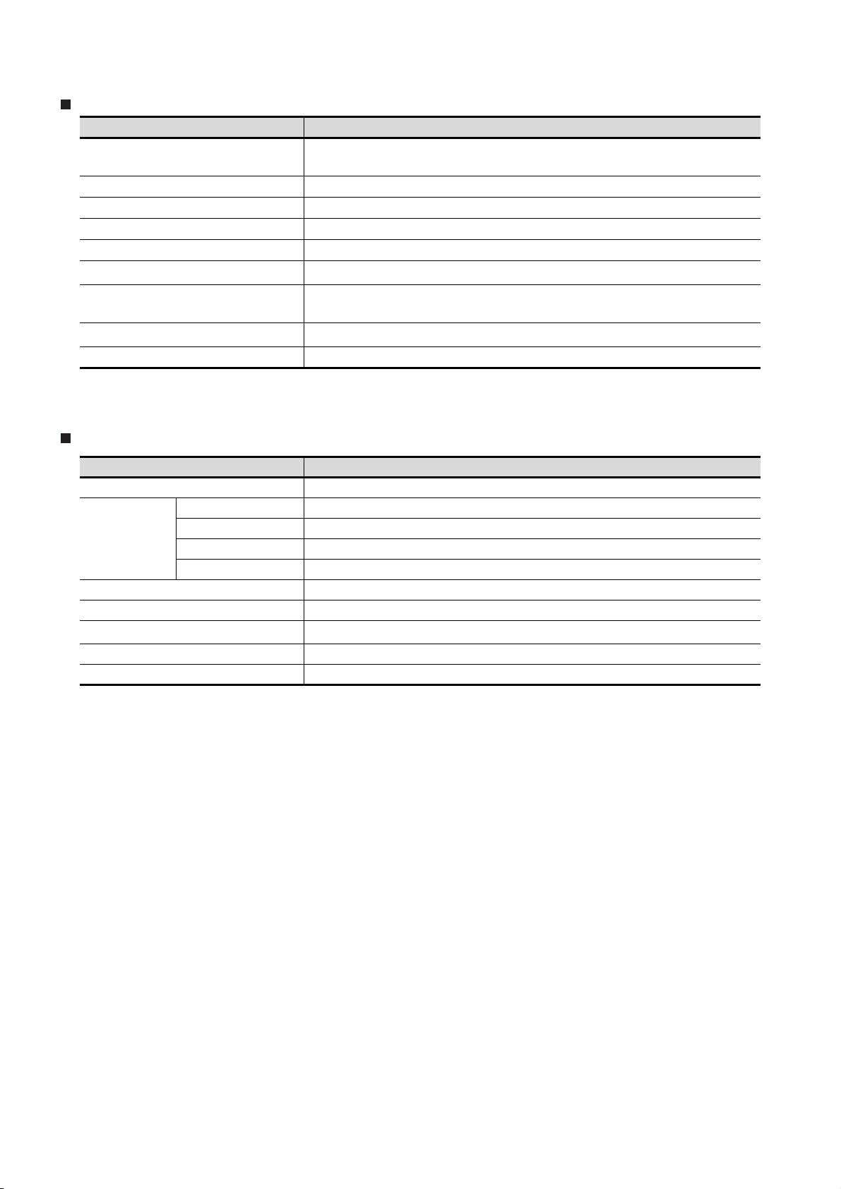
ABOUT MANUALS
The following manuals are also related to this product.
In necessary, order them by quoting the details in the tables below.
The manual in PDF-format is included in the GT Works2 and GT Designer2 products.
Related Manuals
Manual Name
GT SoftGOT1000 Version2 Operating Manual
Describes
GT Designer2 Version2 Basic Operation/Data Transfer Manual (For GOT1000 Series)
Describes methods of the GT Designer2 installation operation, basic operation for drawing and transmitting data to
GOT1000 series.
GT Designer2 Version2 Screen Design Manual (For GOT1000 Series) 1/3
GT Designer2 Version2 Screen Design Manual (For GOT1000 Series) 2/3
GT Designer2 Version2 Screen Design Manual (For GOT1000 Series) 3/3
Describes specifications and settings of the object functions used in GOT1000 series.
GOT1000 Series Connection Manual (1/3)
GOT1000 Series Connection Manual (2/3)
GOT1000 Series Connection Manual (3/3)
Describes system configurations of the connection method applicable to GOT1000 series and cable creation
method.
GOT1000 Series Extended/Option Functions Manual
Describes extended functions and option functions applicable to GOT series.
GOT1000 Series Gateway Functions Manual
Describes specifications, system configurations and setting method of the gateway function.
GOT1000 Series MES Interface Function Manual
Describes the specifications, system configurations, and setting method of the MES interface function.
the screen configuration, functions and using method of GT SoftGOT1000.
(Sold separately)
(Sold separately)
(Sold separately)
(Sold separately)
(Sold separately)
(Sold separately)
(Sold separately)
Manual Number
(Model Code)
SH-080602ENG
(1D7M48)
SH-080529ENG
(1D7M24)
SH-080530ENG
(1D7M25)
SH-080532ENG
(1D7M26)
SH-080544ENG
(1D7M32)
SH-080545ENG
(1D7M33)
SH-080654ENG
(1D7M63)
A - 14
Page 17
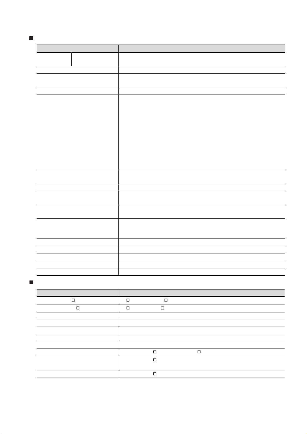
ABBREVIATIONS AND GENERIC TERMS
Abbreviations and generic terms used in this manual are as follows:
GOT
Abbreviations and generic terms Description
GT SoftGOT1000 Abbreviation of GT SoftGOT1000
GT1695 GT1695M-X Abbreviation of GT1695M-XTBA, GT1695M-XTBD
GT1685 GT1685M-S Abbreviation of GT1685M-STBA, GT1685M-STBD
GT1 6 , GT 1 6
GT1595 GT1595-X Abbreviation of GT1595-XTBA, GT1595-XTBD
GT1585
GT1 57
GT1 56
GOT1000 Series
GT1 55
GT15 , GT15 Abbreviation of GT1595, GT1585, GT157 , GT156 , GT155
GT11 5
Handy
GOT
GT11 , GT11 Ab b revi a t ion o f GT115 , GT11 Ha n dy GO T
GT1 05
GT1030 Abbreviation of GT1030-LBD, GT1030-LBD2, GT1030-LBDW, GT1030-LBDW2
GT1020
GT10 , GT10 Abbreviation of GT105 , GT1030, GT1020
GOT900 Series Abbreviation of GOT-A900 series, GOT-F900 series
GOT800 Series Abbreviation of GOT-800 series
GT1585V-S Abbreviation of GT1585V-STBA, GT1585V-STBD
GT1585-S Abbreviation of GT1585-STBA, GT1585-STBD
GT1575V-S Abbreviation of GT1575V-STBA, GT1575V-STBD
GT1575-S Abbreviation of GT1575-STBA, GT1575-STBD
GT1575-V Abbreviation of GT1575-VTBA, GT1575-VTBD
GT1575-VN Abbreviation of GT1575-VNBA, GT1575-VNBD
GT1572-VN Abbreviation of GT1572-VNBA, GT1572-VNBD
GT1565-V Abbreviation of GT1565-VTBA, GT1565-VTBD
GT1562-VN Abbreviation of GT1562-VNBA, GT1562-VNBD
GT1555-V Abbreviation of GT1555-VTBD
GT1555-Q Abbreviation of GT1555-QTBD, GT1555-QSBD
GT1550-Q Abbreviation of GT1550-QLBD
GT11 55-Q
GT1150-Q Abbreviation of GT1150-QLBDQ, GT1150-QLBDA, GT1150-QLBD
GT1155HS-Q Abbreviation of GT1155HS-QSBD
GT1150HS-Q Abbreviation of GT1150HS-QLBD
GT1055-Q Abbreviation of GT1055-QSBD
GT1050-Q Abbreviation of GT1050-QBBD
Abbreviation of GT1695, GT1685
Abbreviation of GT1155-QTBDQ, GT1155-QSBDQ, GT1155-QTBDA, GT1155-QSBDA,
GT11 5 5-QT B D, GT11 5 5 -QSB D
Abbreviation of GT1020-LBD, GT1020-LBD2, GT1020-LBL, GT1020-LBDW,
GT1020-LBDW2, GT1020-LBLW
A - 15
Page 18
Communication unit
Abbreviations and generic terms Description
Bus connection unit
Serial communication unit GT15-RS2-9P, GT15-RS4-9S, GT15-RS4-TE
RS-422 conversion unit GT15-RS2T4-9P, GT15-RS2T4-25P
Ethernet communication unit GT15-J71E71-100
MELSECNET/H communication unit GT15-J71LP23-25, GT15-J71BR13
MELSECNET/10 communication unit
CC-Link IE controller network communication
unit
CC-Link communication unit
Interface converter unit GT15-75IF900
GT15-QBUS, GT15-QBUS2, GT15-ABUS, GT15-ABUS2,
GT15-75QBUSL, GT15-75QBUS2L, GT15-75ABUSL, GT15-75ABUS2L
GT15-75J71LP23-Z*1, GT15-75J71BR13-Z
GT15-J71GP23-SX
GT15-J61BT13, GT15-75J61BT13-Z
*2
*3
*1 A9GT-QJ71LP23 + GT15-75IF900 set
*2 A9GT-QJ71BR13 + GT15-75IF900 set
*3 A8GT-J61BT13 + GT15-75IF900 set
Option unit
Abbreviations and generic terms Description
Printer unit GT15-PRN
Video input unit GT16M-V4, GT15V-75V4
Video/RGB unit
Multimedia unit GT16M-MMR
CF card unit GT15-CFCD
CF card extension unit
External I/O unit GT15-DIO, GT15-DIOR
Sound output unit GT15-SOUT
RGB input unit GT16M-R2, GT15V-75R1
Video/RGB input unit GT16M-V4R1, GT15V-75V4R1
RGB output unit GT16M-ROUT, GT15V-75ROUT
*1
GT15-CFEX-C08SET
*1 GT15-CFEX + GT15-CFEXIF + GT15-C08CF set.
A - 16
Page 19
Option
Abbreviations and generic terms Description
Memory card CF card
Memory card adaptor GT05-MEM-ADPC
Option function board
Battery GT15-BAT, GT11-50BAT
Protective Sheet
Protective cover for oil
USB environmental protection cover GT16-UCOV, GT15-UCOV, GT11-50UCOV
Stan d
Attachment
Backlight
Multi-color display board GT15-XHNB, GT15-VHNB
Connector conversion box GT11H-CNB-37S
Emergency stop sw guard cover GT11H-50ESCOV
Memory loader GT10-LDR
Memory board GT10-50FMB
GT05-MEM-16MC, GT05-MEM-32MC, GT05-MEM-64MC, GT05-MEM-128MC,
GT05-MEM-256MC
GT1 6 -MES B , GT15 - FNB, GT15 - QFN B , GT15- Q FNB1 6 M,
GT15-QFNB32M, GT15-QFNB48M, GT15-MESB48M, GT11-50FNB
GT16-90PSCB, GT16-90PSGB, GT16-90PSCW, GT16-90PSGW,
GT16-80PSCB, GT16-80PSGB, GT16-80PSCW, GT16-80PSGW,
GT15-90PSCB, GT15-90PSGB, GT15-90PSCW, GT15-90PSGW,
GT15-80PSCB, GT15-80PSGB, GT15-80PSCW, GT15-80PSGW,
GT15-70PSCB, GT15-70PSGB, GT15-70PSCW, GT15-70PSGW,
GT15-60PSCB, GT15-60PSGB, GT15-60PSCW, GT15-60PSGW,
GT15-50PSCB, GT15-50PSGB, GT15-50PSCW, GT15-50PSGW,
GT11-50PSCB, GT11-50PSGB, GT11-50PSCW, GT11-50PSGW,
GT11H-50PSC,
GT10-50PSCB, GT10-50PSGB, GT10-50PSCW, GT10-50PSGW,
GT10-30PSCB, GT10-30PSGB, GT10-30PSCW, GT10-30PSGW,
GT10-20PSCB, GT10-20PSGB, GT10-20PSCW, GT10-20PSGW
GT05-90PCO, GT05-80PCO, GT05-70PCO, GT05-60PCO,
GT05-50PCO
GT15-90STAND, GT15-80STAND, GT15-70STAND, A9GT-50STAND,
GT05-50STAND
GT15-70ATT-98, GT15-70ATT-87, GT15-60ATT-97, GT15-60ATT-96,
GT15-60ATT-87, GT15-60ATT-77, GT15-50ATT-95W, GT15-50ATT-85
GT16-90XLTT, GT16-80SLTT, GT15-90XLTT, GT15-80SLTT,
GT15-70SLTT, GT15-70VLTT, GT15-70VLTN, GT15-60VLTT,
GT15-60VLTN
Software
Abbreviations and generic terms Description
GT Works2 Version SW D5C-GTWK2-E, SW D5C-GTWK2-EV
GT Designer2 Version SW D5C-GTD2-E, SW D5C-GTD2-EV
GT Designer2 Abbreviation of screen drawing software GT Designer2 for GOT1000/GOT900 series
GT Converter2 Abbreviation of data conversion software GT Converter2 for GOT1000/GOT900 series
GT Simulator2 Abbreviation of screen simulator GT Simulator 2 for GOT1000 / GOT900 series
GT SoftGOT1000 Abbreviation of monitoring software GT SoftGOT1000
GT SoftGOT2 Abbreviation of monitoring software GT SoftGOT2
GX Developer
GX Simulator
PX Developer
Abbreviation of SW D5C-GPPW-E(-EV)/SW D5F-GPPW-E type software package
Abbreviation of SW D5C-LLT-E(-EV) type ladder logic test tool function software packages
(SW5D5C-LLT (-EV) or later versions)
Abbreviation of SW D5C-FBDQ-E type FBD software package for process control
A - 17
Page 20

License key (for GT SoftGOT1000)
Abbreviations and generic terms Description
License GT15-SGTKEY-U, GT15-SGTKEY-P
License key (for GT SoftGOT2)
Abbreviations and generic terms Description
License key A9GTSOFT-LKEY-P (For DOS/V PC)
License key FD SW5D5F-SGLKEY-J (For PC CPU module)
Others
Abbreviations and generic terms Description
OMRON PLC Abbreviation of PLC manufactured by OMRON Corporation
KEYENCE PLC Abbreviation of PLC manufactured by KEYENCE CORPORATION
KOYO EI PLC Abbreviation of PLC manufactured by KOYO ELECTRONICS INDUSTRIES CO., LTD.
SHARP PLC Abbreviation of PLC manufactured by Sharp Corporation
JTEKT PLC Abbreviation of PLC manufactured by JTEKT Corporation
TOSHIBA PLC Abbreviation of PLC manufactured by TOSHIBA CORPORATION
TOSHIBA MACHINE PLC Abbreviation of PLC manufactured by TOSHIBA MACHINE CO., LTD.
HITACHI IES PLC Abbreviation of PLC manufactured by Hitachi Industrial Equipment Systems Co., Ltd.
HITACHI PLC Abbreviation of PLC manufactured by Hitachi, Ltd.
FUJI FA PLC Abbreviation of PLC manufactured by Fuji Electric FA Components & Systems Co., Ltd.
MATSUSHITA PLC Abbreviation of PLC manufactured by Matsushita Electric Works, Ltd.
YASKAWA PLC Abbreviation of PLC manufactured by YASKAWA Electric Corporation
YOKOGAWA PLC Abbreviation of PLC manufactured by Yokogawa Electric Corporation
ALLEN-BRADLEY PLC Abbreviation of Allen-Bradley PLC manufactured by Rockwell Automation, Inc.
GE FANUC PLC Abbreviation of PLC manufactured by GE Fanuc Automation Corporation
LS IS PLC Abbreviation of PLC manufactured by LS Industrial Systems Co., Ltd.
SCHNEIDER PLC Abbreviation of PLC manufactured by Schneider Electric SA
SIEMENS PLC Abbreviation of PLC manufactured by Siemens AG
OMRON temperature
controller
SHINKO indicating
controller
CHINO controller Abbreviation of temperature controller manufactured by CHINO CORPORATION
Temperature
controller
PC CPU module Abbreviation of PC CPU Unit manufactured by CONTEC CO., LTD
GOT (server) Abbreviation of GOTs that use the server function
GOT (client) Abbreviation of GOTs that use the client function
FUJI SYS temperature
controller
YAMATAKE temperature
controller
YOKOGAWA temperature
controller
RKC temperature
controller
Abbreviation of temperature controller manufactured by OMRON Corporation
Abbreviation of temperature controller manufactured by Shinko Technos Co., Ltd.
Abbreviation of temperature controller manufactured by Fuji Electric Systems Co., Ltd.
Abbreviation of temperature controller manufactured by Yamatake Corporation
Abbreviation of temperature controller manufactured by Yokogawa Electric Corporation
Abbreviation of temperature controller manufactured by RKC INSTRUMENT INC.
Windows font
Intelligent function module
MODBUS /TCP
A - 18
Abbreviation of TrueType font and OpenType font available for Windows
(Differs from the True Type fonts settable with GT Designer2)
Indicates the modules other than the PLC CPU, power supply module and I/O module that are
mounted to the base unit.
Generic term for the protocol designed to use MODBUS protocol messages on a TCP/IP
network.
Page 21
HOW TO USE THIS MANUAL
1 Functions
This manual describes functions available for the GT Designer2 Version2.90U.
For the added functions by the product version upgrade, refer to the list of functions added by GT
Desiger2 version upgrade in Appendices.
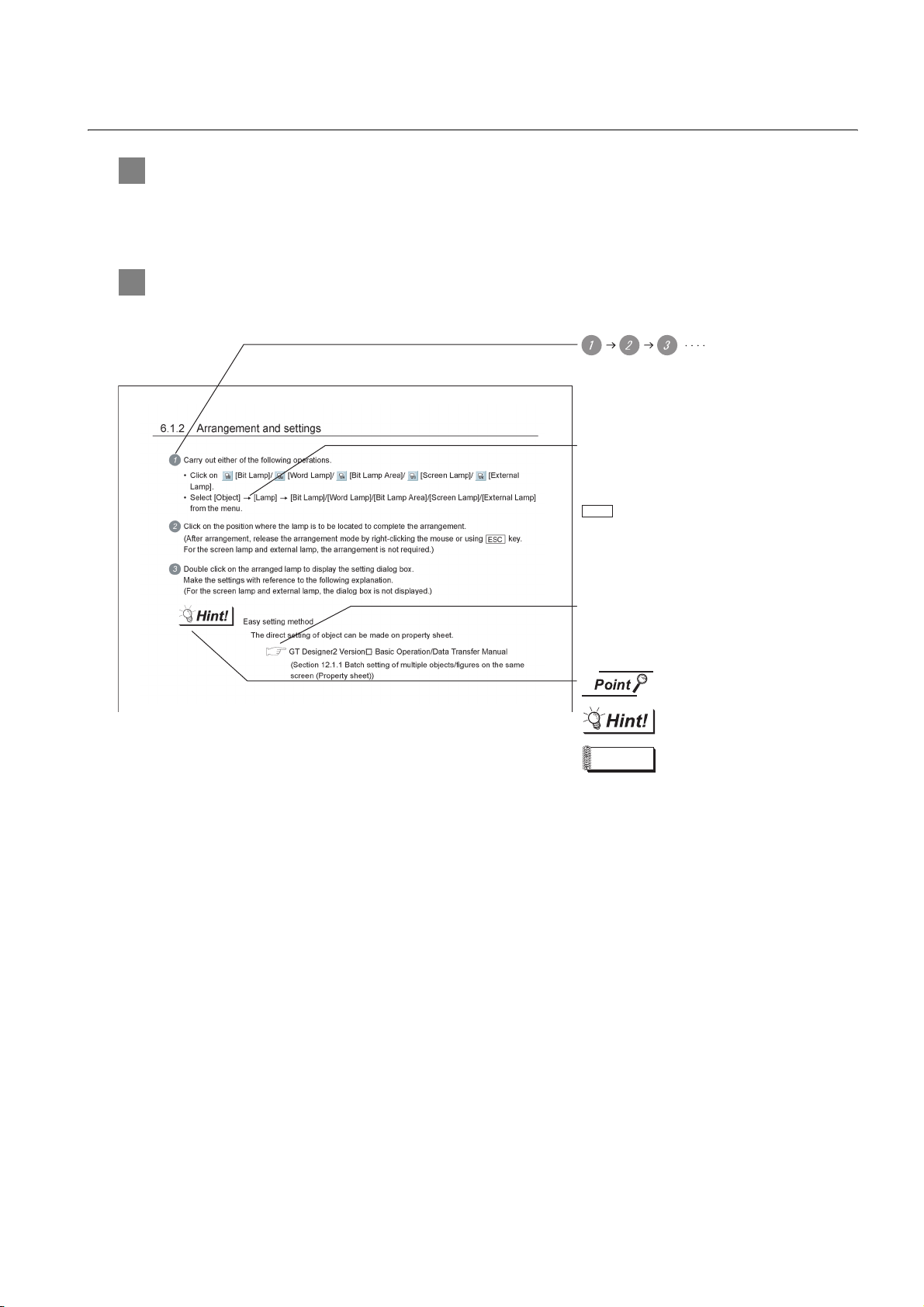
2 Symbols
Following symbols are used in this manual
Indicates the operation steps.
Brackets used for the menu and items differ.
[ ]
:Refers to an item displayed on
the computer screen or the
GOT screen.
:Refers to a button displayed on
the computer screen or the
GOT screen, or a key of the
computer keyboard.
Show the items including detailed explanation
(manual and the chapter, section, item).
Refers to information required
for operation.
Refers to information useful
for operation.
Remark
* The above is different from the actual page, as it is provided for explanation only.
Refers to supplementary
explanations.
A - 19
Page 22

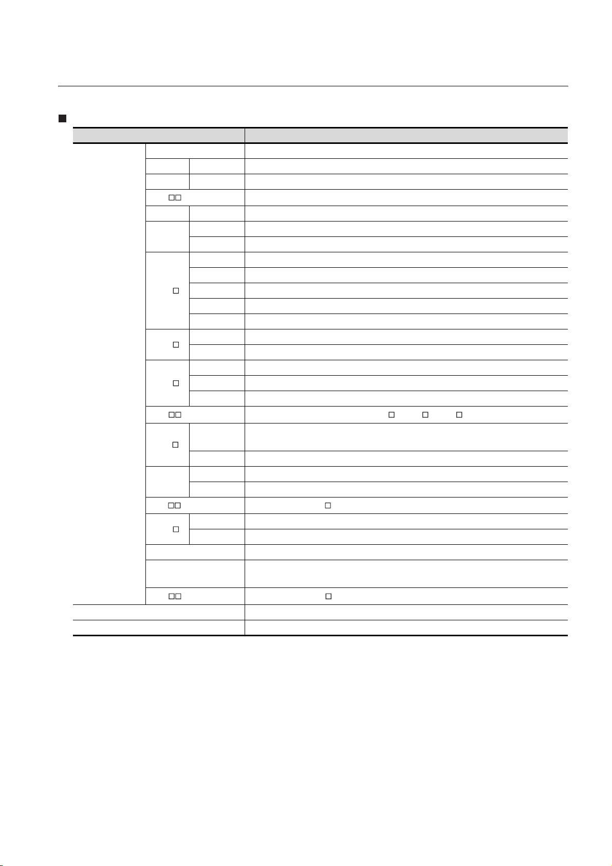
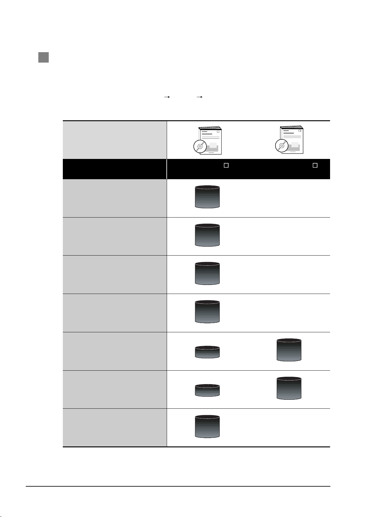
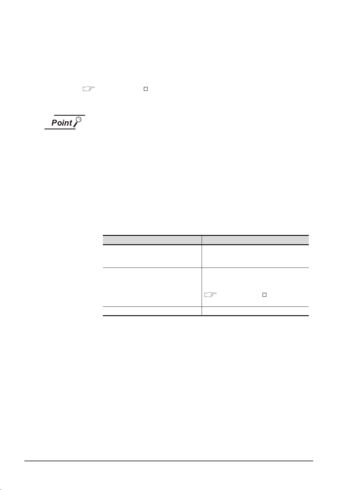
PACKING LIST
After unpacking, confirm that the following parts are included.
Model Product Quantity
GOT 1
GT1695M-X
GT1685M-S
Battery 1
Installation fitting 8
GT16 General Description 1
GOT 1
Battery 1
A - 20
Installation fitting 4
GT16 General Description 1
Page 23
1. OVERVIEW
1
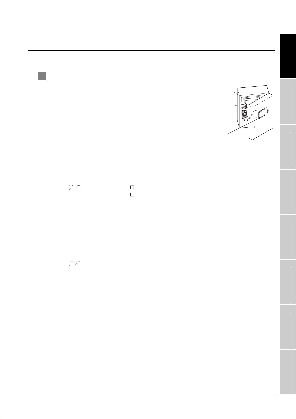
1 About GOT
GOT is installed on the panel surface of control panel or operating
panel and connects to the PLC in the control panel. GOT carries out
switch operation, lamp display, data display, and message display etc.
For display screen, two kinds of display screens, user-created screen
and utility screen are available.
(1) User-created Screen
User screen is a screen drawn by GT Designer2.
The objects of "Touch switch", "Lamp display", "Comment
display", and "Numeric display" can be laid out arbitrarily to be displayed.
Moreover, the multiple screens created by GT Designer2 can be overlapped and switched to be
displayed.
For details, refer to the following.
GT Designer2 Version Basic Operation/Data Transfer Manual
GT Designer2 Version Screen Design Manual
(2) Utility Screen
Utility screen is a screen prepared beforehand for GOT.
Installing BootOS and standard OS in the GOT from GT Designer2 enables utility screen
displaying.
The utility screen has menus as [Brightness/contrast adjustment screen] and [GOT memory check
screen] etc.
PLC
Connector for
program
GOT
OVERVIEW
2
SYSTEM
CONFIGURATION
3
SPECIFICATIONS
4
PART NAME AND
SETTINGS
5
For details, refer to the following.
Chapter 8 to Chapter 13
INSTALLATION
6
WIRING
7
OPTION
8
UTILITY FUNCTION
1 - 1
Page 24
2 About Manual
The following manuals related to GOT1000 series are available. Refer to each manual in accordance
with the intended use.
Stored in the GT Works2/GT Designer2 in PDF format.
(1) Installation of the software programs Drawing Data transfer
For operations from creating project data to transferring data to GOT, refer to the following
manuals.
Purpose
Installing product on PC
Creating projects
Creating screens
Drawing figures
GT Designer2 Version Basic
Operation/Data Transfer Manual
Detailed
Detailed
Detailed
Detailed
GT Designer2 Version
Screen Design Manual
1 - 2
Making Common Settings
Placing/Setting objects
Transferring data to GOT
Overview
Overview
Detailed
Detailed
Detailed
Page 25
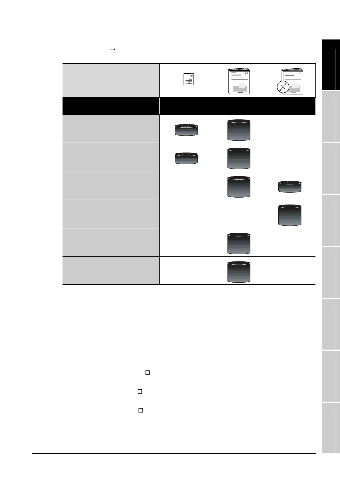
(2) Installing a GOT Connecting to a controller
For the operations from installing a GOT to communicating with a controller, refer to the following manuals
1
.
Purpose
Confirming part names and
specifications of the GOT
Confirming the GOT installation method
Confirming the mounting method for
extension units or option devices
Confirming the PLC connection method
Confirming the utility operation method
(Included)
GT16 General
Description
Overview
Overview
GT16 User's Manual
Detailed
Detailed
Detailed
Detailed
GOT1000 Series
Connection Manual
Overview
Detailed
OVERVIEW
2
SYSTEM
CONFIGURATION
3
SPECIFICATIONS
4
PART NAME AND
SETTINGS
5
Confirming error codes (system alarm)
displayed on the GOT
Detailed
(3) Other manuals
The following manuals are also available.
The following manuals are stored in the GT Works2/GT Designer2 in PDF format.
(a) GOT1000 Series Extended/Option Functions Manual
Describes functions for more efficient debugging as the ladder monitor function, system
monitor function and A list edit function.
(b) GOT1000 Series Gateway Functions Manual
Describes how to use the gateway function.
(c) GT SoftGOT1000 Version Operating Manual
Describes how to use the GT SoftGOT1000 and various functions.
(d) GT Simulator2 Version Operating Manual
Describes how to simulate the created project data with the GT Simulator2.
(e) GT Converter2 Version Operating Manual
Describes how to use the GT Converter2.
(f) GOT1000 Series MES Interface Function Manual
Describes how to use the GT MES Interface Function.
INSTALLATION
6
WIRING
7
OPTION
8
1 - 3
UTILITY FUNCTION
Page 26

1.1 Features
(1) Improved monitoring performance and connectivity to FA devices
• Using of TFT color liquid crystal display (high intensity, wide angle view and high definition type)
provides clear full-color display and displays small characters clearly. (Displays digital images of
BMP and other formats in 65536 colors.)
• Provides multi-language display function based on Unicode2.1 True Type font and high-speed
drawing of beautiful text.
• High speed monitoring through high speed communication at maximum of 115.2kbps.
• High speed display and high speed touch switch response.
• The operation performance is improved by the analog touch panel.
• All models of the video/RGB unit and the multimedia unit are applicable.
(2) More efficient GOT operations including screen design, startup, adjustment, management and
maintenance works
• 15MB user memory is included as standard.
• The RS-232 interface is included as standard.
• The RS-422/485 interface is included as standard.
• The CF card interface is included as standard.
• The Ethernet interface is included as standard.
• Font installation is available to increase the system fonts.
• Combined use of 4 types of alarms (system alarm, user alarm, alarm history, alarm popup
display) realizes more efficient alarm notification.
• Maintenance timing report function is available that measures the backlight energization time
and notifies of maintenance time.
• The USB interface is positioned on the GOT front. This enables the system startup to be
performed more efficiently using FA device startup tool, and eliminates the necessity of indirect
works (opening and closing the control panel, cable replacement, cable rewiring) in order to
improve the working efficiency.
• The blown backlight bulb can be confirmed even during screen saving, with the blinked POWER
LED at backlight shutoff detection.
1 - 4
(3) Enhanced support of FA device setup tools
• Transferring and monitoring sequence programs with the personal computer connected to the
GOT can be executed when connecting to a PLC CPU with the direct CPU connection or bus
connection. (FA transparent function)
1.1 Features
Page 27
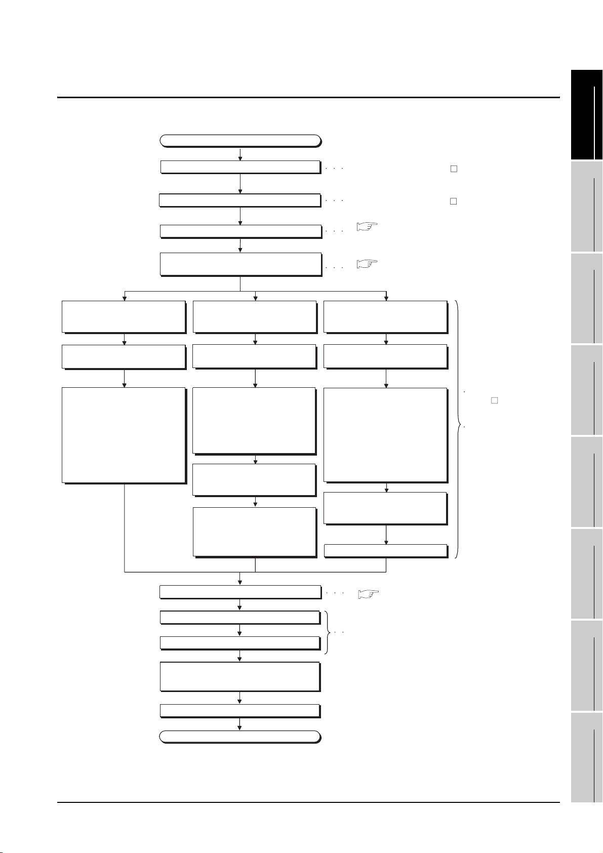
1.2 Rough Pre-operation Procedure
/
The outline procedure before operating GOT is shown.
Start
Install GT Designer2 in the PC.
Refer to GT Designer2 Version
Basic Operation/Data Transfer Manual
1
OVERVIEW
2
When transferring data from PC to
built-in flash memory and starting
GOT with built-in flash memory.
Connect GOT and PC with a USB
cable or RS-232 cable.
Transfer the OS and project data to
be installed on the GOT from the PC
to the GOT.
1) Install standard monitor OS,
communication driver, extended
function OS, option OS to the
GOT.
After installation is completed, the
GOT automatically restarts.
2) Download the project data created
by the PC. *1
Create project data.
Wire for the GOT power supply.
Mount the option function board.
(As necessary)
When transferring data from CF card
to built-in flash memory and starting
GOT with built-in flash memory.
Insert the CF card in the PC.
Write the OS and project data to be
installed on the GOT from the PC to
the CF card.
1) Write the standard monitor OS,
communication driver, extended
function OS, option OS, project
data in the CF card.
Check that the CF card access
switch is off, and insert the CF card
into the GOT.
Turn on the CF card access switch,
and then install or download the
standard monitor OS, communication
driver, option OS, extended function
OS, and project data.
Refer to GT Designer2 Version Screen Design Manual
( 6. WIRING)
Refer to Chapter 6 WIRING
( 7. OPTION)
Refer to Chapter 7 OPTION
When transferring data to CF card
and starting GOT with CF card.
Insert the CF card in the PC.
Write the OS and project data to be
installed on the GOT from the PC to
the CF card.
1) Set the OS boot drive to
[A: Standard CF Card]. *2
2) Write the standard monitor
OS, communication driver,
option OS, extended
function OS, project data,
and special data into the CF card.
Check that the CF card access
switch is off, and insert the CF card
into the GOT.
Turn on the CF card access switch.
Refer to GT Designer2
Version Basic Operation
Data Transfer Manual
Refer to Chapter 14
INSTALLATION
OF COREOS, BOOTOS
AND STANDARD OS in
this manual for the
operations of GOT.
SYSTEM
CONFIGURATION
3
SPECIFICATIONS
4
PART NAME AND
SETTINGS
5
INSTALLATION
6
Mount units to GOT.
Check the Communication settings.
Connect the GOT and controller with a cable.
Turn on the power supply of GOT and
the system of the connection destination.
Start the monitor.
End
Refer to Chapter 7 OPTION
( 7. OPTION)
Refer to GOT1000 Series Connection Manual
1.2 Rough Pre-operation Procedure
WIRING
7
OPTION
8
UTILITY FUNCTION
1 - 5
Page 28
* 1 By connecting with the Ethernet interface included as standard in GT 16, project data can be downloaded/
uploaded.
For download/upload of project data with the Ethernet connection, BootOS and standard monitor OS should be
installed in the GOT in advance so that the GOT and PC can communicate with each other via Ethernet by
setting Communication Settings.
Refer to the following manual for details.
GT Designer2 Version Basic Operation/Data Transfer Manual (Chapter 8 TRANSFERRING DATA)
* 2 The B drive or E drive cannot be set as the OS boot drive.
Precautions for setting OS boot drive to [A: Standard CF Card]
(1) GOT startup time
When the OS boot drive is set to [A: Standard CF Card], the GOT startup time with
the A drive takes longer than that with the C drive.
The GOT startup time with the A drive differs depending on the CF card type, the
numbers of extended function OSs and option OSs, and project data size.
(2) Handling CF card during booting OS
Do not remove the CF card and do not turn off the CF card access switch during
booting the OS.
Doing so causes the boot to fail. As a result, the GOT does not start correctly.
(3) Corrective actions when OS cannot be booted
The OS cannot be booted in the following conditions.
Take the following corrective actions, and then boot the OS again.
Condition Corrective action
The type of the GOT to be used differs from the
GOT type data set with GT Designer2 stored in
the CF card.
The GOT has insufficient memory.
The CF card access switch is off. Turn on the CF card access switch.
Prepare the CF card where the OSs and project data
of the same GOT type as the GOT to be used are
written.
Delete unnecessary data stored in the memory of
GOT.
For details, refer to the following manual.
GT Designer2 Version Basic Operation/
Data Transfer Manual
1 - 6
1.2 Rough Pre-operation Procedure
Page 29
2. SYSTEM CONFIGURATION
1
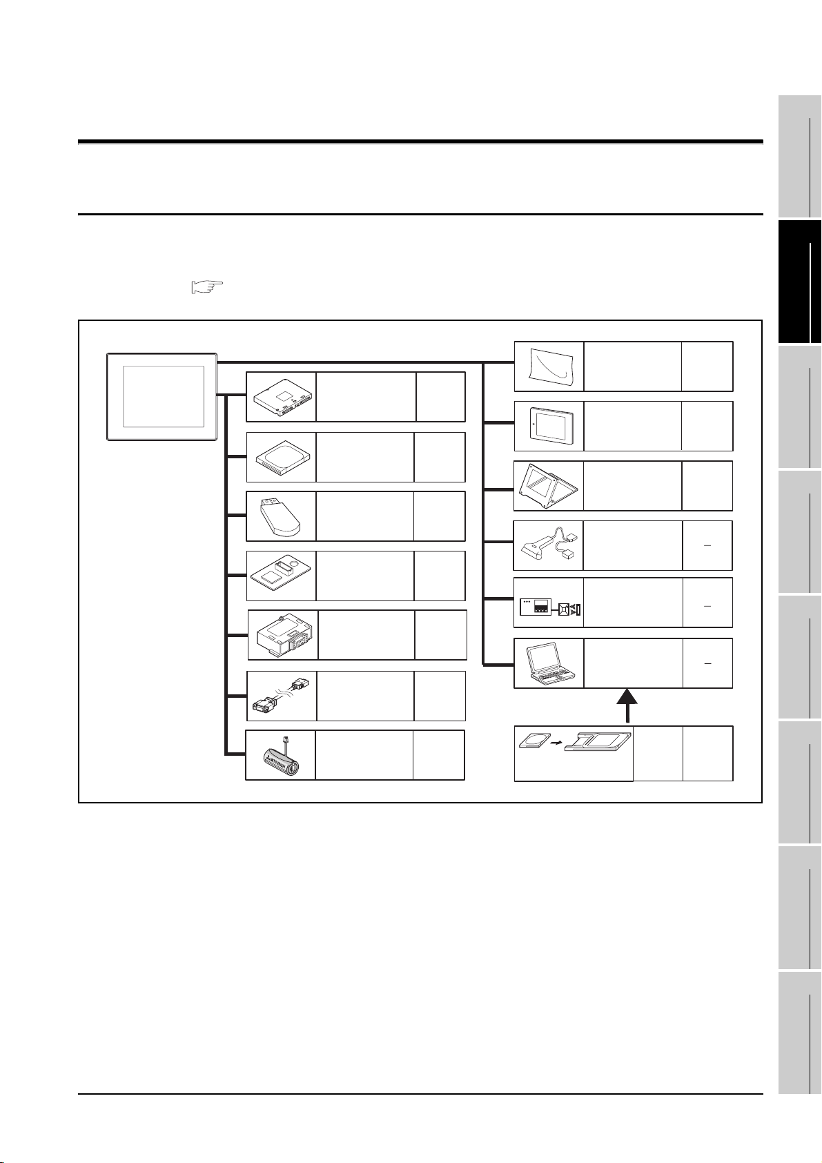
2.1 Overall Configuration
The overall configuration of GOT is as follows.
For the connection methods applicable to GOT1000 series and cable, refer to the following.
GOT1000 Series Connection Manual
Protective sheet
Extension unit
CF card
USB memory
Option function
board
RS-422 conversion
unit
RS-422/485
conversion cable
Refer to
7.1
Protective cover for oil
Refer to
7.3.1
Stand
Refer to
7.5.1
Bar code reader
(Commercially available)
Refer to
7.3.1
RFID controller
(Commercially available)
Refer to
7.4.1
Personal computer
(Commercially available)
Refer to
7.4.1
Refer to
7.3.1
Refer to
7.3.1
Refer to
7.3.1
OVERVIEW
2
SYSTEM
CONFIGURATION
3
SPECIFICATIONS
4
PART NAME AND
SETTINGS
5
INSTALLATION
Battery
Refer to
7.3.1
CF card
Memory card
adaptor
2.1 Overall Configuration
Memory
card
adaptor
Refer to
7.3.1
6
WIRING
7
OPTION
8
UTILITY FUNCTION
2 - 1
Page 30
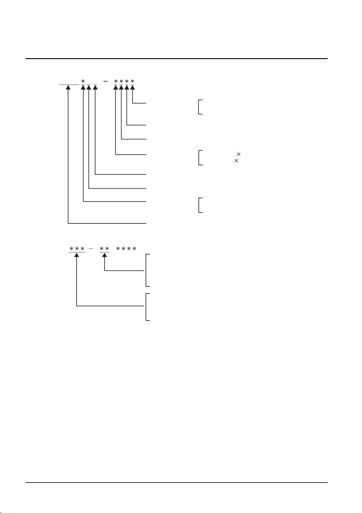
2.2 Component List
(1) Explanation of the GOT model name
GT16 5M
Power type
Panel color type
Display device type
Resolution
Dedicated type
Model type
Screen size type
GOT 1000 series GT16
(2) Explanation of the option model name
GT
(None) : Common for all types
90 : Dedicated for 15"
80 : Dedicated for 12.1"
75 : Common for 15", 12.1"
A : 100 to 240VAC
D : 24VDC
B : Black
T : TFT color (High intensity, Wide angle view)
X : 1024 768 (XGA)
S : 800 600 (SVGA)
M : Multimedia compliant
5 : 65536 colors
9 : 15"
8 : 12.1"
16M : Multimedia compliant model
16 : Dedicated for 16
15 : Common for GT16/GT15,
(Partially dedicated for GT15)
2 - 2
2.2 Component List
Page 31

(3) Third party PLC connection cable
GT09 C
n
1
Connector pin type of the
connection target
(For third party PLC side)
Number of connector pins
(Indicates the number of terminals for solderless or
preparatory-soldered terminals.)
Cable distinction numbers for one manufacturer's
products
(Two-digit sequence number: 01, 02, ...)
* When cable distinction is needed for one manufacture's
products
Example) Wirings are different for each PLC type.
Connecting targets are different, such as servo,
inverter, temperature controller.
Cable classification
P: Plug (male)
S: Socket (female)
T: Solderless terminal
C: Preparatory soldering
01: For OMRON PLC
02: For YASKAWA PLC
03: For YOKOGAWA PLC
04: For HITACHI IEC PLC
05: For TOSHIBA PLC
06: For SHARP PLC
07: For ALLEN-BRADLEY PLC
08: For SIEMENS PLC
09: For MATSUSHITA PLC
11: For KEYENCE PLC
12: For JTEKT PLC
OVERVIEW
2
SYSTEM
CONFIGURATION
3
SPECIFICATIONS
4
PART NAME AND
SETTINGS
5
Application classification
(For GOT1000 side)
Length classification
* Indicated in 10cm unit.
Example) 3m : 30
30m: 300
Third party PLC connection cable
(Commonly used for GT16, GT15 and GT11)
R2: For RS232 communication
R4: For RS422 communication
INSTALLATION
6
WIRING
7
OPTION
8
2.2 Component List
UTILITY FUNCTION
2 - 3
Page 32

2.2.1 GOT
Product
name
GOT
Model name Specifications
GT1695M-XTBA
GT1695M-XTBD
GT1685M-STBA
GT1685M-STBD
15" (1024 768 dots), TFT color liquid crystal, (high intensity, wide angle view),
65536 colors, video/RGB, multimedia compliant, 100 to 240VAC, Memory size 15MB
15" (1024 768 dots), TFT color liquid crystal, (high intensity, wide angle view),
65536 colors, video/RGB, multimedia compliant, 24VDC, Memory size 15MB
12.1" (800 600 dots), TFT color liquid crystal, (high intensity, wide angle view),
65536 colors, video/RGB, multimedia compliant, 100 to 240VAC, Memory size 15MB
12.1" (800 600 dots), TFT color liquid crystal, (high intensity, wide angle view),
65536 colors, video/RGB, multimedia compliant, 24VDC, Memory size 15MB
2 - 4
2.2 Component List
2.2.1 GOT
Page 33

2.2.2 Option
Communication unit (Sold separately)
Product name Model name Description
GT1 5-QB US
GT15-QBUS2
For QCPU (Q Mode)/Motion
controller CPU (Q Series)
connection (standard model)
For last GOT, Number of IN side
connectors: 1
For intermediary and last GOT,
Number of IN and OUT side connectors: 1
for each side
1
OVERVIEW
2
Bus connection unit
Serial communication
unit
MELSECNET/H
communication unit
CC-Link IE controller
network
communication unit
GT15-ABUS
GT15-ABUS2
GT15-75QBUSL
GT15-75QBUS2L
GT15-75ABUSL
GT15-75ABUS2L
GT15-RS2 For RS-232 interface connection, connector type
GT15-RS4 For RS-422 interface connection, connector type
GT15-RS4-TE For RS-422 interface connection, terminal block type
GT15-J71LP23-25 Optical double loop unit
GT15-J71BR13 Coaxial bus unit
GT15-J71GP23-SX Optical loop unit
For A/QnACPU/Motion
controller
connection (standard model)
For QCPU (Q Mode)/Motion
controller CPU (Q Series)
connection (slim model)
For A/QnACPU/Motion
controller CPU (A Series)
connection (slim model)
CPU
(A Series)
For last GOT, Number of IN side
connectors: 1
For intermediary and last GOT,
Number of IN and OUT side connectors: 1
for each side
For last GOT, Number of IN side
connectors: 1
For intermediary and last GOT,
Number of IN and OUT side connectors: 1
for each side
For last GOT, Number of IN side
connectors: 1
For intermediary and last GOT,
Number of IN and OUT side connectors: 1
for each side
SYSTEM
CONFIGURATION
3
SPECIFICATIONS
4
PART NAME AND
SETTINGS
5
INSTALLATION
6
CC-Link
communication unit
GT15-J61BT13
Intelligent device station unit
CC-LINK Ver. 2 compliant
2.2 Component List
2.2.2 Option
WIRING
7
OPTION
8
UTILITY FUNCTION
2 - 5
Page 34

QCPU (Q Mode) bus connection cable (Sold separately)
Product name Model name Description
GT15-QC06B Cable length 0.6m
Q extension cable
GOT-to-GOT
connection cable
Q long distance
connection cable
GOT-to-GOT long
distance connection
cable
GT15-QC12B Cable length 1.2m
GT15-QC30B Cable length 3m
GT15-QC50B Cable length 5m
GT15-QC100B Cable length 10m
GT15-QC150BS Cable length 15m
GT15-QC200BS Cable length 20m
GT15-QC250BS Cable length 25m
GT15-QC300BS Cable length 30m
GT15-QC350BS Cable length 35m
For connecting QCPU and GOT
For connecting GOT and GOT
For long distance connection (13.2m or longer)
of QCPU and GOT (A9GT-QCNB is necessary)
For long distance connection of GOT and GOT
QnA/ACPU/Motion controller (A series) bus connection cable (Sold separately)
Product name Model name Description
Small-size CPU
extension cable
GOT-to-GOT
connection cable
Large-size CPU
extension cable
GT15-A1SC07B Cable length 0.7m
GT15-A1SC12B Cable length 1.2m
GT15-A1SC30B Cable length 3m
GT15-A1SC50B Cable length 5m For connecting QnAS/AnSCPU and GOT
GT15-A1SC05NB Cable length 0.45m
GT15-A1SC07NB Cable length 0.7m
GT15-A1SC30NB Cable length 3m
GT15-A1SC50NB Cable length 5m For connecting QnAS/AnSCPU and A7GT-CNB
GT15-C12NB Cable length 1.2m
GT15-C30NB Cable length 3m
GT15-C50NB Cable length 5m
GT15-AC06B Cable length 0.6m
GT15-AC12B Cable length 1.2m
GT15-AC30B Cable length 3m
GT15-AC50B Cable length 5m
GT15-A370C12B-S1 Cable length 1.2m
GT15-A370C25B-S1 Cable length 2.5m
GT15-A370C12B Cable length 1.2m
GT15-A370C25B Cable length 2.5m
For connecting QnAS/AnSCPU/Motion controller
CPU (A series) and GOT
For connecting QnAS/AnSCPU/motion controller
CPU (A series) and A7GT-CNB
For connecting QnA/ACPU/Motion controller
CPU (A series /Extension base) and GOT
For connecting QnA/ACPU/Motion controller
CPU (A series /Extension base) and A7GT-CNB
For connecting Motion controller CPU (A series /
Extension base) and GOT
For connecting Motion controller CPU (A series /
Extension base) and A7GT-CNB
Small-size CPU
long distance
connection cable
2 - 6
GT15-C100EXSS-1 Cable length 10.6m
GT15-C200EXSS-1 Cable length 20.6m
GT15-C300EXSS-1 Cable length 30.6m
2.2 Component List
2.2.2 Option
For long distance connection of QnAS/AnSCPU/
motion controller CPU (A series) and GOT
For connecting A7GT-CNB and a combined
product of the GT15-EXCNB and GT15-C BS (for
long distance connection)
(Continued to next page)
Page 35

Product name Model name Description
GT15-C07BS Cable length 0.7m
GOT-to-GOT
connection cable
GOT-to-GOT long
distance connection
cable
A0J2HCPU
connection cable
Buffer circuit cable GT15-EXCNB Cable length 0.5m
GT15-C12BS Cable length 1.2m
GT15-C30BS Cable length 3m
GT15-C50BS Cable length 5m
GT15-C100BS Cable length 10m
GT15-C200BS Cable length 20m
GT15-C300BS Cable length 30m
GT15-J2C10B Cable length 1m
For connecting GOT and GOT
For connecting A0J2HCPU power supply module
(A0J2-PW) and GOT
Combined with GT15-C BS, can be used as
GT15-C EXSS-1
Connection cables for MITSUBISHI PLCs (Sold separately)
Product name Model name Description
RS-232
cable
QCPU direct
connection cable
FX communication
function extension
board connection
cable,
FX communication
function adapter
connection cable,
data transfer cable
FX communication
function adaptor
connection cable,
data transfer cable
Computer link
connection cable
GT01-C30R2-6P Cable length 3m For connecting QCPU and GOT
For connecting FXCPU communication
function extension board (D-sub 9 pins
connector), FXCPU communication function
GT01-C30R2-9S Cable length 3m
GT01-C30R2-25P Cable length 3m
GT09-C30R2-9P Cable length 3 m
GT09-C30R2-25P Cable length 3 m
adapter (D-sub 9 pins connector) and GOT
For connecting personal computer (Drawing
software) (D-sub 9 pins: female) and GOT
(D-sub 9 pins: female)
For connecting FXCPU communcation
function adaptor (D-sub 25 pins connector)
and GOT
For connecting computer link module/serial
communication module and GOT
1
OVERVIEW
2
SYSTEM
CONFIGURATION
3
SPECIFICATIONS
4
PART NAME AND
SETTINGS
5
INSTALLATION
6
(Continued to next page)
2.2 Component List
2.2.2 Option
WIRING
7
OPTION
8
UTILITY FUNCTION
2 - 7
Page 36

Product name Model name Description
GT01-C10R4-8P Cable length 1m
RS-422
cable
FXCPU direct
connection cable,
FX communication
function extension
board connection
cable
QnA/A/FXCPU
direct connection
cable, computer
link connection
cable
Computer link
connection cable
GT01-C30R4-8P Cable length 3m
GT01-C100R4-8P Cable length 10m
GT01-C200R4-8P Cable length 20m
GT01-C300R4-8P Cable length 30m
GT01-C30R4-25P Cable length 3m
GT01-C100R4-25P Cable length 10m
GT01-C200R4-25P Cable length 20m
GT01-C300R4-25P Cable length 30m
GT09-C30R4-6C Cable length 3 m
GT09-C100R4-6C Cable length 10 m
GT09-C200R4-6C Cable length 20 m
For connecting FXCPU (MINI DIN 8 pins
connector) and GOT
For connecting FXCPU communication
function extension board (MINI DIN 8 pins
connector) and GOT
For connecting QnA/ACPU/Motion controller
CPU (A series)/FXCPU (D-sub 25 pins
connector) and GOT
For connecting FA-CNV
For connecting computer link module/serial
communication module and GOT
For connecting computer link module/serial
communication module and GOT
CBL and GOT
GT09-C300R4-6C Cable length 30 m
Connection cables for OMRON PLCs (Sold separately)
Product
name
RS-232
cable
Model name Description
GT09-C30R20101-9P Cable length 3m
GT09-C30R20102-25S Cable length 3m For connecting GOT to OMRON connection cable
GT09-C30R20103-25P Cable length 3m For connecting GOT to OMRON rack type host link unit
For connecting GOT to OMRON PLC, serial communication
module, communication board, serial communication board
(Continued to next page)
2 - 8
2.2 Component List
2.2.2 Option
Page 37

Product
name
Model name Description
GT09-C30R40101-9P Cable length 3m
GT09-C100R40101-9P Cable length 10m
GT09-C200R40101-9P Cable length 20m
GT09-C300R40101-9P Cable length 30m
GT09-C30R40102-9P Cable length 3m
For connecting GOT to OMRON PLC, serial communication
module, serial communication board
1
OVERVIEW
2
RS-422
cable
GT09-C100R40102-9P Cable length 10m
GT09-C200R40102-9P Cable length 20m
GT09-C300R40102-9P Cable length 30m
GT09-C30R40103-5T Cable length 3m
GT09-C100R40103-5T Cable length 10m
GT09-C200R40103-5T Cable length 20m
GT09-C300R40103-5T Cable length 30m
For connecting GOT to OMRON rack type host link unit,
communication board
For connecting GOT to OMRON communication board
(CP1W-CIF11)
Connection cables for KEYENCE PLCs (Sold separately)
Product
name
RS-232
cable
RS-422
cable
Model name Description
GT09-C30R21101-6P Cable length 3m For connecting GOT to KEYENCE PLC
GT09-C30R21102-9S Cable length 3m For connecting GOT to KEYENCE multi-communication unit
GT09-C30R21103-3T Cable length 3m For connecting GOT to KEYENCE multi-communication unit
GT09-C30R41101-5T Cable length 3m
GT09-C100R41101-5T Cable length 10m
For connecting GOT to KEYENCE multi-communication unit
GT09-C200R41101-5T Cable length 20m
GT09-C300R41101-5T Cable length 30m
SYSTEM
CONFIGURATION
3
SPECIFICATIONS
4
PART NAME AND
SETTINGS
5
Connection cables for SHARP PLCs (Sold separately)
Product
name
RS-232
cable
RS-422
cable
Model name Description
GT09-C30R20601-15P Cable length 3m For connecting GOT to SHARP PLC
GT09-C30R20602-15P Cable length 3m For connecting GOT to SHARP PLC
GT09-C30R40601-15P Cable length 3m
GT09-C100R40601-15P Cable length 10m
GT09-C200R40601-15P Cable length 20m
GT09-C300R40601-15P Cable length 30m
GT09-C30R40602-15P Cable length 3m
GT09-C100R40602-15P Cable length 10m
GT09-C200R40602-15P Cable length 20m
GT09-C300R40602-15P Cable length 30m
GT09-C30R40603-6T Cable length 3m
GT09-C100R40603-6T Cable length 10m
GT09-C200R40603-6T Cable length 20m
GT09-C300R40603-6T Cable length 30m
For connecting GOT to SHARP PLC
For connecting GOT to SHARP PLC
For connecting GOT to SHARP link unit
2.2 Component List
2.2.2 Option
INSTALLATION
6
WIRING
7
OPTION
8
UTILITY FUNCTION
2 - 9
Page 38

Connection cables for JTEKT PLCs (Sold separately)
Product
name
RS-232
cable
RS-422
cable
Model name Description
GT09-C30R21201-25P Cable length 3 m For connecting GOT to JTEKT PLC
GT09-C30R41201-6C Cable length 3 m
GT09-C100R41201-6C Cable length 10 m
GT09-C200R41201-6C Cable length 20 m
GT09-C300R41201-6C Cable length 30 m
For connecting GOT to JTEKT PLC
Connection cables for SHINKO indicating controller (Sold separately)
Product
name
RS-232
cable
Model name Description
GT09-C30R21401-4T Cable length 3m
For connecting GOT to SHINKO indicating controller (FCR100/FCD100/FCR-23A/PC-/FIR series)
Connection cables for TOSHIBA PLCs (Sold separately)
Product
name
RS-232
cable
RS-422
cable
Model name Description
GT09-C30R20501-9P Cable length 3m For connecting GOT to TOSHIBA PLC
GT09-C30R20502-15P Cable length 3m For connecting GOT to TOSHIBA PLC
GT09-C30R40501-15P Cable length 3m
GT09-C100R40501-15P Cable length 10m
GT09-C200R40501-15P Cable length 20m
GT09-C300R40501-15P Cable length 30m
GT09-C30R40502-6C Cable length 3m
GT09-C100R40502-6C Cable length 10m
GT09-C200R40502-6C Cable length 20m
GT09-C300R40502-6C Cable length 30m
GT09-C30R40503-15P Cable length 3m
GT09-C100R40503-15P Cable length 10m
GT09-C200R40503-15P Cable length 20m
GT09-C300R40503-15P Cable length 30m
For connecting GOT to TOSHIBA PLC
For connecting GOT to TOSHIBA PLC
For connecting GOT to TOSHIBA PLC
Connection cables for HITACHI IES PLCs (Sold separately)
Product
name
RS-232
cable
RS-422
cable
2 - 10
Model name Description
GT09-C30R20401-15P Cable length 3m
GT09-C30R20402-15P Cable length 3m For connecting GOT to HITACHI IES PLC
GT09-C30R40401-7T Cable length 3m
GT09-C100R40401-7T Cable length 10m
GT09-C200R40401-7T Cable length 20m
GT09-C300R40401-7T Cable length 30m
2.2 Component List
2.2.2 Option
For connecting GOT to HITACHI IES PLC, intelligent serial
port module
For connecting GOT to HITACHI IES intelligent serial port
module
Page 39

Connection cables for HITACHI PLCs (Sold separately)
1
Product
name
RS-232
Cable
RS-422
Cable
Model name Description
GT09-C30R21301-9S Cable length 3m
GT09-C30R41301-9S Cable length 3m
GT09-C100R41301-9S Cable length 10m
GT09-C200R41301-9S Cable length 20m
GT09-C300R41301-9S Cable length 30m
For connecting GOT to HITACHI communication module
(LQE560/LQE060/LQE160)
For connecting GOT to HITACHI PLC (LPQ510) and
communication module (LQE565/LQE165)
Connection cables for FUJI FA PLCs (Sold separately)
Product
name
RS-232
Cable
RS-422
Cable
Model name Description
For connecting GOT to FUJI FA RS-232C interface
GT09-C30R21003-25P Cable length 3m
GT09-C30R41001-6T Cable length 3m
GT09-C100R41001-6T Cable length 10m
GT09-C200R41001-6T Cable length 20m
GT09-C300R41001-6T Cable length 30m
card(NV1L-RS2), RS-232C/485 interface capsule(FFK120AC10), and general-purpose interface module(NC1L-RS2/
FFU120B)
For connecting GOT to FUJI FA RS-232C/485 interface
capsule(FFK120A-C10) and general-purpose interface
module(NC1L-RS4/FFU120B)
2
SYSTEM
3
4
OVERVIEW
CONFIGURATION
SPECIFICATIONS
Connection cables for MATSUSHITA PLCs (Sold separately)
Product
name
RS-232
cable
Model name Description
GT09-C30R20901-25P Cable length 3m
GT09-C30R20902-9P Cable length 3m
GT09-C30R20903-9P Cable length 3m
GT09-C30R20904-3C Cable length 3m
For connecting GOT to MATSUSHITA RS422/232C
conversion adapter
For connecting GOT to the tool port or RS232C port of
MATSUSHITA PLC, computer communication unit
For connecting GOT to the RS232C port of MATSUSHITA
PLC
For connecting GOT to the RS232C port of MATSUSHITA
PLC
PART NAME AND
SETTINGS
5
INSTALLATION
6
WIRING
7
OPTION
2.2 Component List
2.2.2 Option
8
UTILITY FUNCTION
2 - 11
Page 40

Connection cables for YASKAWA PLCs (Sold separately)
Product
name
RS-232
cable
RS-422
cable
Model name Description
GT09-C30R20201-9P Cable length 3m
GT09-C30R20202-15P Cable length 3m
For connecting GOT to YASKAWA PLC
GT09-C30R20203-9P Cable length 3m
GT09-C30R20204-14P Cable length 3m
GT09-C30R20205-25P Cable length 3m For connecting GOT to YASKAWA MEMOBUS module
GT09-C30R40201-9P Cable length 3m
GT09-C100R40201-9P Cable length 10m
For connecting GOT to YASKAWA MEMOBUS module
GT09-C200R40201-9P Cable length 20m
GT09-C300R40201-9P Cable length 30m
GT09-C30R40202-14P Cable length 3m
GT09-C100R40202-14P Cable length 10m
For connecting GOT to YASKAWA PLC
GT09-C200R40202-14P Cable length 20m
GT09-C300R40202-14P Cable length 30m
Connection cables for YOKOGAWA PLCs (Sold separately)
Product
name
RS-232
cable
Model name Description
GT09-C30R20301-9P Cable length 3m
GT09-C30R20302-9P Cable length 3m For connecting GOT to YOKOGAWA PC link module
GT09-C30R20304-9S Cable length 3m
GT09-C30R40301-6T Cable length 3m
GT09-C100R40301-6T Cable length 10m
For connecting GOT to YOKOGAWA CPU port/D-Sub 9-pin
conversion cable
For connecting GOT to YOKOGAWA converter (ML2-
)
RS-422
cable
GT09-C200R40301-6T Cable length 20m
GT09-C300R40301-6T Cable length 30m
GT09-C30R40302-6T Cable length 3m
GT09-C100R40302-6T Cable length 10m
GT09-C200R40302-6T Cable length 20m
GT09-C300R40302-6T Cable length 30m
GT09-C30R40303-6T Cable length 3m
GT09-C100R40303-6T Cable length 10m
GT09-C200R40303-6T Cable length 20m
GT09-C300R40303-6T Cable length 30m
GT09-C30R40304-6T Cable length 3m
GT09-C100R40304-6T Cable length 10m
GT09-C200R40304-6T Cable length 20m
GT09-C300R40304-6T Cable length 30m
For connecting GOT to YOKOGAWA PC link module
For connecting GOT to YOKOGAWA temperature controller
(GREEN series)
For connecting GOT to YOKOGAWA temperature controller
(UT2000 series)
2 - 12
2.2 Component List
2.2.2 Option
Page 41

Connection cables for ALLEN-BRADLEY PLCs (Sold separately)
1
Product
name
RS-232
cable
Model name Description
GT09-C30R20701-9S Cable length 3m For connecting GOT to ALLEN-BRADLEY PLC
Connection cables for SIEMENS PLCs (Sold separately)
Product
name
RS-232
cable
Model name Description
GT09-C30R20801-9S Cable length 3m For connecting GOT to SIEMENS HMI Adapter
RS-422 connector conversion cable (Sold separately)
Product name Model name Description
RS-422 connector
conversion cable
GT16-C02R4-9S
RS-422/485(connector)
RS-422 connector
conversion cable
RS-422 side connector 9 pins
RS-485 connector terminal block conversion modules with cable (Sold separately)
Product name Model name Description
RS-485
connector terminal
block conversion
modules with cable
FA-LTBGTR4CBL05 Cable length 0.5m
FA-LTBGTR4CBL10 Cable length 1.0m
FA-LTBGTR4CBL20 Cable length 2.0m
RS-422/485 connector RS-485
(terminal block) converter module with
dedicated connection cable
OVERVIEW
2
SYSTEM
CONFIGURATION
3
SPECIFICATIONS
4
PART NAME AND
SETTINGS
RS-422 conversion unit (Sold separately)
Product name Model name Description
RS-422 conversion
unit
GT15-RS2T4-9P
GT15-RS2T4-25P RS-422 side connector 25 pins
RS-232 RS-422
conversion unit
RS-422 side connector 9 pins
Bus extension connector box (Sold separately)
Product name Model name Description
Bus extension
connector box
A9GT-QCNB
For QCPU (Q Mode)/Motion controller CPU (Q series) long distance
(13.2m or longer) bus connection
Bus connector conversion box (Sold separately)
Product name Model name Description
Bus connector
conversion
box
A7GT-CNB
For QnA/ACPU/Motion controller CPU (A series) long distance bus
connection (For conversion from large type connector to small type
connector)
5
INSTALLATION
6
WIRING
7
OPTION
8
2.2 Component List
2.2.2 Option
UTILITY FUNCTION
2 - 13
Page 42

CF card (Sold separately)
Product name Model name Description
GT05-MEM-16MC Flash ROM 16MB
GT05-MEM-32MC Flash ROM 32MB
GT05-MEM-64MC Flash ROM 64MB
CF card
GT05-MEM-128MC Flash ROM 128MB
GT05-MEM-256MC Flash ROM 256MB
Commercially-available CF card
*2: Some models with the operations checked by our company are usable.
For the operation-checked models, refer to "List of valid devices applicable for GOT1000 series" (T10-0039)
separately available.
The Technical News above is available as a reference at the information site for Mitsubishi industrial automation
products MELFANSweb home page.
(MELFANSweb website: http://wwwf2.mitsubishielectric.co.jp/english/index.html)
USB memory (Sold separately)
Product name Model name Description
USB memory
*3: Some models with the operations checked by our company are usable.
For the operation-checked models, refer to "List of valid devices applicable for GOT1000 series" (T10-0039)
separately available.
The Technical News above is available as a reference at the information site for Mitsubishi industrial automation
products MELFANSweb home page.
(MELFANSweb website: http://wwwf2.mitsubishielectric.co.jp/english/index.html)
Commercially-available USB memory
Bar code reader (Sold separately)
*2
*3
Product name Model name Description
Bar code reader
*4: Some models with the operations checked by our company are usable.
For the operation-checked models, refer to "List of valid devices applicable for GOT1000 series" (T10-0039)
separately available.
The Technical News above is available as a reference at the information site for Mitsubishi industrial automation
products MELFANSweb home page.
(MELFANSweb website: http://wwwf2.mitsubishielectric.co.jp/english/index.html)
Commercially-available bar code reader
RFID controller (Sold separately)
Product name Model name Description
RFID controller
*5: Some models with the operations checked by our company are usable.
For the operation-checked models, refer to "List of valid devices applicable for GOT1000 series" (T10-0039)
separately available.
The Technical News above is available as a reference at the information site for Mitsubishi industrial automation
products MELFANSweb home page.
(MELFANSweb website: http://wwwf2.mitsubishielectric.co.jp/english/index.html)
Commercially-available RFID controller
Memory card adaptor (Sold separately)
Product name Model name Description
Memory card adaptor GT05-MEM-ADPC
CF card to memory card (Type II) conversion adaptor
*4
*5
Option function board (Sold separately)
Product name Model name Description
Option function board GT16-MESB MES interface function boad
2 - 14
2.2 Component List
2.2.2 Option
Page 43

Option unit (Sold separately)
Product name Model name Description
Video input unit GT16M-V4 For video input signal (NTSC format / PAL format) 4 channels
RGB input unit GT16M-R2 For analog RGB input signal 2 channels
1
Video/RGB input unit GT16M-V4R1
RGB output unit GT16M-ROUT For analog RGB output signal 1 channel
Multimedia unit GT16M-MMR For video input signal (NTSC format / PAL format) 1 channel
Printer unit GT15-PRN
CF card unit GT15-CFCD For CF card installation (B drive)
CF card extention unit GT15-CFEX-C08SET For CF card installation (B drive)
GT1 5-DI O
External I/O unit
GT1 5-DI OR
Sound output unit GT15-SOUT For sound output
For video input signal (NTSC format / PAL format) 4 channels/analog
RGB input signal 1 channels mixed input
For connecting a
printer
For connecting an external I/O device/operation panel (Positive
Common Input/Sink Type Output)
For connecting an external I/O device/operation panel
Common Input/Source Type Output)
USB slave (PictBridge) 1 channel
(Negative
Option unit dedicated cable (Sold separately)
Product name Model name Description
Dedicated printer
connection cable
*6: Included with an option unit at the time of purchase.
GT09-C30USB-5P Cable length 3m For connecting GOT (USB mini) to printer (USB)
*6
Stand (Sold separately)
OVERVIEW
2
SYSTEM
CONFIGURATION
3
SPECIFICATIONS
4
PART NAME AND
SETTINGS
5
Product name Model name Description
Stand
GT15-90STAND Stand for 15"
GT15-80STAND Stand for 12.1"
Battery (Sold separately)
Product name Model name Description
Battery
*7
*7: Included with the main unit.
GT15-BAT Battery for clock data and maintenance report data backups
Protective sheet (Sold separately)
Product name Model name Description
GT16-90PSCB
GT16-90PSGB Antiglare 5 sheets
15" protective sheet
GT16-90PSCW Clear (Frame: white) 5 sheets
GT16-90PSGW Antiglare (Frame: white) 5 sheets
Protective sheet
GT16-80PSCB
GT16-80PSGB Antiglare 5 sheets
12.1" protective sheet
GT16-80PSCW Clear (Frame: white) 5 sheets
GT16-80PSGW Antiglare (Frame: white) 5 sheets
Clear 5 sheets
Clear 5 sheets
INSTALLATION
6
WIRING
7
OPTION
8
2.2 Component List
2.2.2 Option
UTILITY FUNCTION
2 - 15
Page 44

Protective cover for oil (Sold separately)
Product name Model name Description
Protective cover for
oil
GT05-90PCO For 15" GOT
GT05-80PCO For 12.1" GOT
Backlight (Sold separately)
Product name Model name Description
Backlight
*8
GT16-90XLTT For 15" high intensity, wide angle view TFT (XGA) GT1695M-X
GT16-80SLTT For 12.1" high intensity, wide angle view TFT (SVGA) GT1685M-S
*8: At GOT purchase, it is installed in the main unit.
USB environmental protection cover (Sold separately)
Product name Model name Description
USB environmental
protection cover
*9
*9: At GOT purchase, it is installed in the main body.
GT1 6-U COV
Environmental cover for USB interface on the GOT
main unit front side (For complying IP67)
Drawing software (Sold separately)
Product name Model name Description
SW
D5C-GTD2-J
GT Designer2
* 10: The is assigned with an integer 2 or more.
( indicates the
version)
*10
Drawing software for GOT1000/GOT900 series
PC connection cable (Sold separately)
Product name Model name Description
GT01-C30R2-9S Cable length 3m
GT01-C30R2-25P Cable length 3m
Project data
transfer cable
GT09-C20USB-5P Cable length 2m
GT09-C30USB-5P Cable length 3m
For connecting GOT (D sub 9-pin female)
and PC (D sub 9-pin female)
For connecting GOT (D sub 9-pin female)
and PC (D sub 25-pin male)
For connecting GOT (USB mini) and PC
(USB)
For connecting GOT (USB mini) and PC
(USB)
15", 12.1"
2 - 16
2.2 Component List
2.2.2 Option
Page 45

3. SPECIFICATIONS
3.1 General Specifications
Item Specifications
1
OVERVIEW
2
Operating
ambient
temperature
Storage ambient temperature -20 to 60°C
Operating ambient humidity 10 to 90% RH, non-condensing
Storage ambient humidity 10 to 90% RH, non-condensing
Vibration resistance
Shock resistance
Operating atmosphere No corrosive gas
Operating altitude
Installation location Inside control panel
Overvoltage category
Pollution degree
Cooling method Self-cooling
Display section 0 to 50°C
Other than the
*1
display section
*2
*3
*4
0 to 55°C
Compliant
with JIS
B3502 and
IEC61131-2
Compliant with JIS B3502, IEC 61131-2 (147 m/s
directions)
2000 m (6562 ft) max.
II or less
2 or less
Under
intermittent
vibration
Under
continuous
vibration
Frequency Acceleration
5 to 9Hz - 3.5mm
9 to 150Hz
5 to 9Hz - 1.75mm
9 to 150Hz
2
9.8m/s
2
4.9m/s
2
, 3 times each in X, Y and Z
Half-
amplitude
-
-
Sweep count
10 times each
in X, Y and Z
directions
SYSTEM
CONFIGURATION
3
SPECIFICATIONS
4
PART NAME AND
SETTINGS
5
INSTALLATION
6
Grounding
Grounding with a resistance of 100 or less
*1 When mounting a multimedia unit (GT16M-MMR), MELSECNET/H communication unit (GT15-J71LP23-25,
GT15-J71BR13), or CC-Link communication unit (GT15-J61BT13), the operating ambient temperature must be
reduced 5 °C against the maximum values described in general specifications.
*2 Do not use or store the GOT under pressure higher than the atmospheric pressure of altitude 0m (0ft.). Failure to
observe this instruction may cause a malfunction.
*3 This indicates the section of the power supply to which the equipment is assumed to be connected between the
public electrical power distribution network and the machinery within the premises.
Category II applies to equipment for which electrical power is supplied from fixed facilities.
The surge voltage withstand level for up to the raged voltage of 300 V is 2500 V.
*4 This index indicates the degree to which conductive material is generated in the environment where the
equipment is used.
In pollution degree 2, only non-conductive pollution occurs but temporary conductivity may be produced due to
condensation.
3.1 General Specifications
3 - 1
WIRING
7
OPTION
8
UTILITY FUNCTION
Page 46

3.2 Performance Specifications
The performance specifications of the GT16 is as follows.
3.2.1 GT1695M-X
3.2.2 GT1685M-S
3.2.1 GT1695M-X
Display
section
Backlight
Item
Type TFT color liquid crystal display (High intensity and wide angle view)
Screen size 15"
Resolution 1,024 768 dots
Display size 304.1(12.0)(W) 228.1(8.98)(H) [mm](inch)
Display character
Display color 65536 colors
*1
Display angle
Intensity of LCD only 450 [cd/m²]
Intensity adjustment 8-level adjustment
Life Approx. 52,000 h (Operating ambient temperature : 25°C)
*2
Life
Type Analog resistive film
16-dot standard font: 64 characters 48 lines (2byte character)
12-dot standard font: 85 characters 64 lines (2byte character)
Left/Right: 75 degrees
Top: 50 degrees
Bottom: 60 degrees
Cold cathode fluorescent tube (replaceable) backlight shutoff detection function is
included
Backlight off/screen saving time can be set.
Approx. 50,000 h or longer
(Time when display luminance reaches 50% at the operating ambient temperature
of 25°C)
GT1695M-XTBA GT1695M-XTBD
Specifications
3 - 2
Touch
panel
Key size Minimum 2 2 dots (per key)
Number of objects that
can be simultaneously
touched
Life 1 million times or more (operating force 0.98N max.)
3.2 Performance Specifications
3.2.1 GT1695M-X
Simultaneous presses not allowed.
(Only 1 point can be touched.)
(Continued to next page)
Page 47

Item
Detection length 1(39.37) [m](inch)
Human
sensor
Memory
Battery GT15-BAT lithium battery
Detection range Left/Right/Top/Bottom: 70 degrees
Detection delay time 0 to 4s
Detection temperature Temperature difference between human body and ambient air: 4°C or higher
C drive Built-in flash memory 15Mbytes (for storing project data and OS)
*3
Life (Number of
write times)
Backup target Clock data and maintenance time notification data, system log data
Life Approx. 5 years (Operating ambiant temperature of 25°C)
RS-232
RS-422/485
*5
*5
100,000 times
RS-232, 1ch
Transmission speed: 115,200/57,600/38,400/19,200/9,600/4,800 bps
Connector shape: D-sub 9-pin (Male)
Application: For communicating with a controller or connecting a personal
computer (Project data upload/download, OS installation, FA transparent function)
RS-422/485, 1ch
Transmission speed: 115,200/57,600/38,400/19,200/9,600/4,800 bps
Connector shape: 14-pin (female)
Application: For communicating with a controller.
GT1695M-XTBA GT1695M-XTBD
Specifications
1
2
SYSTEM
3
4
OVERVIEW
CONFIGURATION
SPECIFICATIONS
Data transfer method: 100BASE-TX, 1ch
Connector shape: RJ-45 (modular jack)
Ethernet
Built-in
interface
USB
CF card
Option function board For option function board mounting, 1ch
Extension unit
Buzzer output Single tone (tone length adjustable)
Protective structure
External dimensions 397(15.6)(W) 296(11.7)(H) 61(2.40)(D)[mm](inch)
*5
Application: For communicating with a controller, using the gateway function, or
connecting a personal computer (Project data upload/download, OS installation,
MES interface function)
USB (Full Speed 12Mbps), Host, 1ch
Connector shape: TYPE-A
Application:Data transfer, data storage
USB (Full Speed 12Mbps), Device, 1ch
Connector shape: TYPE Mini-B
Application: For connecting a personal computer (Project data upload/download,
OS installation, FA transparent function)
Compact flash slot, 1ch
Connector shape: TYPE I
Application: Data transfer, data storage, GOT startup
For communication unit/option unit mounting, 2ch
Outside the enclosure: IP67
Inside the enclosure: IP2X
*4
PART NAME AND
SETTINGS
5
INSTALLATION
6
WIRING
7
OPTION
8
Panel cutting dimensions 383.5(15.1)(W) 282.5(11.1)(H)[mm](inch)
Weight 5.0kg(11.0lb) (mounting fixtures are not included)
3.2 Performance Specifications
3.2.1 GT1695M-X
UTILITY FUNCTION
3 - 3
Page 48

Item
Compatible software package
(GT Designer2 Version)
*1 Bright dots (always lit) and dark dots (unlit) may appear on a liquid crystal display panel due to its characteristics.
It is impossible to completely avoid this symptom, as the liquid crystal display comprises of a great number of
display elements. Please note that these dots appear due to its characteristic and are not caused by product
defect.
*2 The GOT screen saving/backlight off function prevents images from becoming permanently etched on the display
screen and increases the backlight life.
*3 ROM in which new data can be written without deleting the written data.
*4 Compliant with IP67 (JEM1030) when the USB environmental protection cover is attached with the part of the
cover firmly pushed into. (Compliant with IP2X (JEM1030) at the USB interface when a USB cable or USB
memory is connected.) Note that this does not guarantee all users' operation environment.
In addition, the GOT may not be available for use in the environment where oil or chemicals are splashed over for
a long period or where oil mist is filled.
*5 For using multiple extension units, a bar code reader, or a RFID controller, the total current for the extension
units, bar code reader, or RFID controller must be within the current that the GOT can supply.
For the current for the extension units, bar code reader or RFID controller, and the current that the GOT can
supply, refer to the following manual.
GT Designer2 Version Screen Design Manual (2.8 Multi-channel Function)
Specifications
GT1695M-XTBA GT1695M-XTBD
2.90U or later
3 - 4
3.2 Performance Specifications
3.2.1 GT1695M-X
Page 49

3.2.2 GT1685M-S
1
Display
section*1
Backlight
Item
Type TFT color liquid crystal display (High intensity and wide angle view)
Screen size 12.1”
Resolution 800 600 dots
Display size 246(9.69)(W) 184.5(7.26)(H) [mm](inch)
Display character
Display color 65536 colors
Display angle
Intensity of LCD only
Intensity adjustment 8-level adjustment
Life Approx. 52,000 h (Operating ambient temperature: 25°C)
16-dot standard font: 50 characters 37 lines (2byte character)
12-dot standard font: 66 characters 50 lines (2byte character)
Left/Right: 80 degrees
Top: 60 degrees
Bottom: 80 degrees
470 [cd/m2]
Cold cathode fluorescent tube (replaceable) backlight shutoff detection function is
included.
Backlight off/screen saving time can be set.
GT1685M-STBA GT1685M-STBD
Specifications
2
SYSTEM
3
4
OVERVIEW
CONFIGURATION
SPECIFICATIONS
Approx. 50,000 h or longer
*2
Life
Type Analog resistive film
Key size Minimum 2 2 dots (per key)
Touch
panel
Human
Sensor
Memory
Battery GT15-BAT lithium battery
Number of objects that
can be simultaneously
touched
Life 1 million times or more (operating force 0.98N max.)
Detection length 1(39.37) [m](inch)
Detection range Left/Right/Top/Bottom: 70 degrees
Detection delay time 0 to 4s
Detection temperature Temperature difference between human body and ambient air: 4°C or higher
C drive Built-in flash memory 15Mbytes (for storing project data and OS)
*3
Life (Number of
write times)
Backup target Clock data and maintenance time notification data, system log data
Life Approx. 5 years (Operating ambient temperature of 25
(Time when display luminance reaches 50% at the operating ambient temperature
of 25
°C)
Simultaneous presses not allowed.
(Only 1 point can be touched.)
100,000 times
°C)
(Continued to next page)
PART NAME AND
SETTINGS
5
INSTALLATION
6
WIRING
7
OPTION
8
3.2 Performance Specifications
3.2.2 GT1685M-S
UTILITY FUNCTION
3 - 5
Page 50

Built-in
interface
Item
RS-232
*5
RS-422/485
Ethernet
USB
Specifications
GT1685M-STBA GT1685M-STBD
RS-232, 1ch
Transmission speed: 15,200/57,600/38,400/19,200/9,600/4,800 bps
Connector shape: D-sub 9-pin (Male)
Application: For communicating with a controller or connecting a personal
computer (Project data upload/download, OS installation, FA transparent
function)
RS-422/485, 1ch
*5
Transmission speed: 115,200/57,600/38,400/19,200/9,600/4,800 bps
Connector shape: 14-pin (female)
Application: For communicating with a controller.
Data transfer method: 100BASE-TX, 1ch
Connector shape: RJ-45 (modular jack)
Application: For communicating with a controller, using the gateway function, or
connecting a personal computer (Project data upload/download, OS installation,
MES interface function)
USB (Full Speed 12Mbps), Host, 1ch
Connector shape: TYPE-A
Application:Data transfer, data storage
USB (Full Speed 12Mbps), Device, 1ch
Connector shape: TYPE Mini-B
Application: For connecting a personal computer (Project data upload/download,
OS installation, FA transparent function)
Compact flash slot, 1ch
CF card
Connector shape: TYPE I
Application: Data transfer, data storage, GOT startup
Option function board For option function board mounting, 1ch
Extension unit
*5
For communication unit/option unit mounting, 2ch
Buzzer output Single tone (tone length adjustable)
Protective structure
Outside the enclosure: IP67
Inside the enclosure: IP2X
*4
External dimensions 316(12.44)(W) × 242(9.53)(H) × 52(2.05)(D) [mm](inch)
Panel cutting dimensions 302(11.89)(W) × 228(8.98)(H)[mm](inch)
Weight 2.7 kg(5.9lb) (mounting fixtures are not included)
Compatible software package
(GT Designer2 Version)
*1 Bright dots (always lit) and dark dots (unlit) may appear on a liquid crystal display panel due to its characteristics.
It is impossible to completely avoid this symptom, as the liquid crystal display comprises of a great number of
display elements. Please note that these dots appear due to its characteristic and are not caused by product
defect.
*2 The GOT screen saving/backlight off function prevents images from becoming permanently etched on the display
screen and increases the backlight life.
*3 ROM in which new data can be written without deleting the written data.
2.90U or later
3 - 6
3.2 Performance Specifications
3.2.2 GT1685M-S
Page 51

*4 Compliant with IP67 (JEM1030) when the USB environmental protection cover is attached with the part of the
cover firmly pushed into. (Compliant with IP2X (JEM1030) at the USB interface when a USB cable or USB
memory is connected.) Note that this does not guarantee all users' operation environment.
In addition, the GOT may not be available for use in the environment where oil or chemicals are splashed over for
a long period or where oil mist is filled.
*5 For using multiple extension units, a bar code reader, or a RFID controller, the total current for the extension
units, bar code reader, or RFID controller must be within the current that the GOT can supply.
For the current for the extension units, bar code reader or RFID controller, and the current that the GOT can
supply, refer to the following manual.
GT Designer2 Version Screen Design Manual (2.8 Multi-channel Function)
1
2
SYSTEM
OVERVIEW
CONFIGURATION
3
SPECIFICATIONS
4
PART NAME AND
SETTINGS
5
INSTALLATION
6
WIRING
7
OPTION
3.2 Performance Specifications
3.2.2 GT1685M-S
8
UTILITY FUNCTION
3 - 7
Page 52

3.3 Power Supply Specifications
The following describes the power supply specifications for the GT16.
3.3.1 For GOTs powered from the 100 to 240VAC power supply
3.3.2 For GOTs powered from the 24VDC power supply
Remark
Operation at momentary failure
• If an instantaneous power failure occurs in the power supply and continues
for more than the permissible period, the GOT will be reset.
• Make sure to power on the unit more than 5 seconds after power-off.
3.3.1 For GOTs powered from the 100 to 240VAC power supply
Item
Input power supply voltage 100 to 240VAC (+10% -15%)
Input frequency
Input max. apparent power 150VA (maximum load) 110VA (maximum load)
Power consumption 64W or less 46W or less
At backlight off 38W or less 32W or less
Inrush current 26A or less (4ms) (maximum load)
Permissible instantaneous
power failure time
Noise immunity
50/60Hz 5%
20ms or less (100VAC or more)
1,500Vp-p noise voltage, 1µs noise width (when measuring with a noise simulator
under 25 to 60Hz noise frequency)
GT1695M-XTBA GT1685M-STBA
Specifications
Dielectric withstand voltage 1500VAC for 1 minute across power terminals and earth
Insulation resistance
Applicable wire size
Applicable solderless terminal Solderless terminal for M3 screw RAV1.25-3, V2-S3.3, V2-N3A, FV2-N3A
Applicable tightening torque
(Terminal block terminal screw)
3 - 8
3.3 Power Supply Specifications
3.3.1 For GOTs powered from the 100 to 240VAC power supply
10M or more across power terminals and earth by a 500V DC insulation resistance
tester
2
0.75 to 2 [mm
0.5 to 0.8 [N•m]
]
Page 53

3.3.2 For GOTs powered from the 24VDC power supply
1
Item
Input power
supply voltage
Power
consumption
At backlight
off
Inrush current 12A or less (75ms) (maximum load) 11A or less (40ms)(maximum load)
Permissible
instantaneous
power failure time
Noise immunity
Dielectric
withstand voltage
Insulation
resistance
Applicable wire
size
Applicable
solderless
terminal
Applicable
tightening torque
(Terminal block
terminal screw)
24VDC (+25%, -20%)
60W or less 40W or less
30W or less 26W or less
10 ms or less
500Vp-p noise voltage, 1 s noise width (when measuring with a noise simulator under 25 to 60Hz
noise frequency)
500VDC for 1 minute across power terminals and earth
10M or more across power terminals and earth by a 500V DC insulation resistance tester
0.75 to 2 [mm²]
Solderess terminal for M3 screw RAV1.25-3, V2-S3.3, V2-N3A, FV2-N3A
0.5 to 0.8 [N•m]
GT1695M-XTBD GT1685M-STBD
Specifications
OVERVIEW
2
SYSTEM
CONFIGURATION
3
SPECIFICATIONS
4
PART NAME AND
SETTINGS
5
INSTALLATION
6
3.3 Power Supply Specifications
3.3.2 For GOTs powered from the 24VDC power supply
WIRING
7
OPTION
8
UTILITY FUNCTION
3 - 9
Page 54

3.4 Battery Specifications
1 Battery specifications
The following describes the battery specifications for the GT16.
Item Specifications
Type Magnesium manganese dioxide lithium primary battery
Initial voltage 3.0V
Nominal current 1800mAh
Storage life Approx.5 years (Operating ambient temperature of 25°C)
Total power stoppage time
Lithium content 0.00049kg
Application
For backup of clock data, maintenance timing setting data and
Refer to This Section Battery life
2 Battery life
Life span of the battery set in the GOT is shown below.
Battery life
Operating ambient
temperature of 25° to 45°C
4 years 3 years 14 days
*: In the following conditions, the data backup time is 5 minutes after the power supply is turned off.
• The battery connector is disconnected.
• The battery lead is disconnected.
Battery life and replacement time
1. Battery life reference: Approx.4 years in actual use (Ambient temperature: 25
Battery replacement time reference: 3 to 4 years
Calculate the natural discharge amount of the battery, as necessary.
Operating ambient
temperature
Other than 25 to 45°C
system log data.
Data backup time after detection
of battery voltage low*
°C)
3 - 10
2. Check if the battery condition is normal within the utility.
Refer to the following for the details of battery status display.
9.1.1 Time setting
3.4 Battery Specifications
3.3.2 For GOTs powered from the 24VDC power supply
Page 55

4. PART NAME AND SETTINGS
1
4.1 Part Names and Settings of the GT1695
21)
2), 3)
1)
4)
5)
19)
OVERVIEW
2
SYSTEM
CONFIGURATION
3
SPECIFICATIONS
4
PART NAME AND
SETTINGS
6)
7) 8) 9)
10) 11) 20)18)
22)
12)
13)
14)
5
INSTALLATION
6
WIRING
7
OPTION
8
17) 16) 15)
4.1 Part Names and Settings of the GT1695
UTILITY FUNCTION
4 - 1
Page 56

No. Name Description
Lit in green : Power is correctly supplied
1) POWER LED
2) Display screen Displays the Utility and the user creation screen.
3) Touch key For operating the touch switches in the Utility and the user creation screen
4) USB interface (Device)
5) USB interface (Host)
Lit in orange : Screen saving
Blinks in orange/green : Blown back light bulb
Not lit : Power is not supplied
For connecting a personal computer
(Connector type: MINI-B)
For data transfer and storage
(Connector type: TYPE-A)
6) RS-232 interface
7) Ethernet interface
8) RS-422/485 interface
9) Power terminal Power input terminal, LG terminal, FG terminal
10) Extension interface1 For installing an extension unit (I/F-1)
11) Extension interface2 For installing an extension unit (I/F-2)
12) CF card interface For installing a CF card
13) CF card access LED
14) CF card access switch
15) Video/RGB interface
Terminating resistor setting dip
16)
switch (inside the cover)
For communicating with a controller or connecting a personal computer
(Connector type: D sub 9-pin)
For communicating with a controller or using the gateway function
(Connector type: RJ-45 (modular jack))
For communicating with a controller
(Connector type: 14-pin (female))
Lit : CF card accessed
Not lit: CF card not accessed
Used for accepting or stopping the access to the CF card before removing the CF
card from the GOT
ON : CF card being accessed (CF card removal prohibited)
OFF : CF card not accessed (CF card removal possible)
For mounting the video input unit, RGB input unit, video/RGB input unit, RGB
output unit, or multimedia unit
For switching on and off of the terminating resistor for the RS-422/485
communication port
Optional function board
17)
interface
18) Reset switch
19) Hole for unit installation fitting Hole for inserting the unit installation fitting
20) Battery holder Houses the battery.
21) Human sensor Sensor that detects human movement
22) Installation switch Used for OS installations at the GOT startup
4 - 2
4.1 Part Names and Settings of the GT1695
For installing the optional function board
Hardware reset switch
(Inoperative in the bus connection or with the bus connection unit installed)
Page 57

1
Remark
Connector used for the RS-232 interface
The specification of the connector used for the RS-232 interface of GT1695 is as
follows.
Manufacturer :DDK Ltd.
Model name :17LE-23090-27 (D4CK) or equivalent product
Connector used for the RS-422/485 interface
The specification of the connector used for the RS-422/485 interface of GT1695 is
as follows.
Manufacturer :Honda Tsushin Kogyo Co., Ltd.
Model name :HDR-EC14LFDT1-SLE+ or equivalent product
2
SYSTEM
3
4
OVERVIEW
CONFIGURATION
SPECIFICATIONS
PART NAME AND
SETTINGS
5
INSTALLATION
6
WIRING
7
OPTION
4.1 Part Names and Settings of the GT1695
8
UTILITY FUNCTION
4 - 3
Page 58

4.2 Part Names and Settings of the GT1685
21)
2), 3)
1)
4)
5)
19)
10)
17) 16)15)
11)
6)
7) 8) 9)
20)
22)
12)
18)
13)
14)
4 - 4
4.2 Part Names and Settings of the GT1685
Page 59

No. Name Description
Lit in green : Power is correctly supplied
1) POWER LED
2) Display screen Displays the Utility and the user creation screen.
3) Touch key For operating the touch switches in the Utility and the user creation screen
Lit in orange : Screen saving
Blinks in orange/green : Blown back light bulb
Not lit : Power is not supplied
1
OVERVIEW
2
4) USB interface (Device)
5) USB interface (Host)
6) RS-232 interface
7) Ethernet interface
8) RS-422/485 interface
9) Power terminal Power input terminal, LG terminal, FG terminal
10) Extension interface1 For installing an extension unit (I/F-1)
11) Extension interface2 For installing an extension unit (I/F-2)
12) CF card interface For installing a CF card
13) CF card access LED
14) CF card access switch
For connecting a personal computer
(Connector type: MINI-B)
For data transfer and storage
(Connector type: TYPE-A)
For communicating with a controller or connecting a personal computer
(Connector type: D sub 9-pin)
For communicating with a controller or using the gateway function
(Connector type: RJ-45 (modular jack))
For communicating with a controller
(Connector type: 14-pin (female))
Lit : CF card accessed
Not lit : CF card not accessed
Used for stopping the access to the CF card before removing the CF card from the
GOT
ON : CF card being accessed (CF card removal prohibited)
OFF : CF card not accessed (CF card removal possible)
SYSTEM
CONFIGURATION
3
SPECIFICATIONS
4
PART NAME AND
SETTINGS
5
15) Video/RGB interface
Terminating resistor setting
16)
switch (inside the cover)
Optional function board
17)
interface
18) Reset switch
19) Hole for unit installation fitting Hole for inserting the unit installation fitting
20) Battely holder Houses the battery
21) Human sensor Sensor that detects human movement
22) Installation switch Used for OS installations at the GOT startup
For mounting the video input unit, RGB input unit, video/RGB input unit, RGB
output unit, or multimedia unit
For switching on and off of the terminating resistor for the RS-422/485
communication port
For installing the optional function board
Hardware reset switch
(Inoperative in the bus connection or with the bus connection unit installed)
4.2 Part Names and Settings of the GT1685
INSTALLATION
6
WIRING
7
OPTION
8
UTILITY FUNCTION
4 - 5
Page 60

Remark
Connector used for the RS-232 interface
The specification of the connector used for the RS-232 interface of GT1685 is as
follows.
Manufacturer :DDK Ltd.
Model name :17LE-23090-27 (D4CK) or equivalent product
Connector used for the RS-422/485 interface
The specification of the connector used for the RS-422/485 interface of GT1685 is
as follows.
Manufacturer :Honda Tsushin Kogyo Co., Ltd.
Model name :HDR-EC14LFDT1-SLE+ or equivalent product
4 - 6
4.2 Part Names and Settings of the GT1685
Page 61

5. INSTALLATION
1
CAUTION
Use the GOT in the environment that satisfies the general specifications described in this manual.
Do not expose the GOT to dust, lamp soot, conductive dust, corrosive gas, or combustible gas;
high-temperature, condensing, wind or rain; or to vibrations and impact.
Failure to do so can cause an electric shock, fire, malfunction or product damage or deterioration.
Do not drop chips or wire scraps near the ventilation window of the GOT when processing screw
holes or wiring.
Failure to do so can cause a fire, failure or malfunction.
Tighten the mounting screws within the specified torque range.
Undertightening can cause the GOT to drop, short circuit or malfunction.
Overtightening can cause a drop, short-circuit or malfunction due to the damage of the screws or
the unit.
Make sure to install the connection cable to the connector specified during the power OFF.
Failure to do so may cause a malfunction due to the poor contact.
5.1 Control Panel Inside Dimensions for Mounting
GOT
OVERVIEW
2
SYSTEM
CONFIGURATION
3
SPECIFICATIONS
4
PART NAME AND
SETTINGS
Install the GOT and the CF card extension unit on the control panel out of the way for the equipment inside
the control panel. Do not install the GOT and the unit in prohibited areas for the installation.
Applicable cable
Some cables may need to be longer than the specified dimensions when connecting
to the GOT.
Therefore, consider the connector dimensions and bending radius of the cable as
well for installation.
5
INSTALLATION
6
WIRING
7
OPTION
8
5.1 Control Panel Inside Dimensions for Mounting GOT
UTILITY FUNCTION
5 - 1
Page 62

5.2 Panel Cutting Dimensions
(1) Panel cutting dimensions when installing GOT
Make a installation hole on the control panel with the dimensions shown below.
Make space of 10mm above and below the hole respectively for the installation fittings.
A
* Panel thickness: 2 to 4 mm or less
GOT A [mm] (inch) B [mm] (inch)
GT1695
GT1685
383.5(15.1)
(+2(0.08), 0(0))
302(11.89)
(+2(0.08), 0(0))
B
(2) Panel cutting dimensions when installing CF card extension unit
Make a installation hole on the control panel with the dimensions shown below.
Make space of 10mm on the left and right of the hole respectively for the installation fittings.
A
B
* Panel thickness: 2 to 4 mm or less
GOT A [mm] (inch) B [mm] (inch)
GT1 5-
CFEX-
C08SET
94(3.7)
(+2(0.08), 0(0))
282.5(11.12)
(+2(0.08), 0(0))
228(8.98)
(+2(0.08), 0(0))
33(1.3)
(+2(0.08), 0 (0))
5 - 2
5.2 Panel Cutting Dimensions
Page 63

5.3 Mounting Position
1 For installing GOT
When mounting the GOT, the following clearances must be left from the other device.
Some cables may need to be longer than the specified dimensions when connecting to the GOT.
Therefore, consider the connector dimensions and bending radius of the cable as well for installation.
For the lead-in allowance for cables at the bottom of the GOT, refer to the following.
Appendix 1 External Dimensions
BA
1
2
SYSTEM
3
OVERVIEW
CONFIGURATION
C
ED
SPECIFICATIONS
4
Panel thickness:
2 to 4mm
(0.08 to 0.16inch)
PART NAME AND
SETTINGS
5
INSTALLATION
6
5.3 Mounting Position
WIRING
7
OPTION
8
UTILITY FUNCTION
5 - 3
Page 64

Type GT1695 GT1685
GOT only
50(1.97) or more [20(0.79) or more]Bus connection unit is fitted
Serial communication unit fitted
RS-422 Conversion unit is fitted 50(1.97) or more 51(2.01) or more
CC-Link communication
unit (GT15-J61BT13) fitted
50 (1.97) or more [20 (0.79) or more]
MELSECNET/H communication unit
(coaxial) fitted
MELSECNET/H communication unit
(optical) fitted
CC-Link IE controller network
A
communication unit fitted
Video input unit fitted
RGB input unit fitted
Video/RGB input unit fitted
RGB output unit fitted
Multimedia unit fitted
Printer unit fitted
CF card unit
CF card extension unit
External I/O unit
Sound output unit
B 80 (3.15) or more [20 (0.79) or more]
(When the CF card is not used)
C
(When the CF card is used)
D 50 (1.97) or more [20 (0.79) or more]
50 (1.97) or more [20 (0.79) or more] 50 (1.97) or more [24 (0.95) or more]
50 (1.97) or more [20 (0.79) or more]
50 (1.97) or more [20 (0.79) or more]
E 100 (39.4) or more [20 (0.79) or more]
Unit: mm (inch)
The values enclosed in parenthesis apply to the case where no other equipment generating radiated noise
(such as a contactor) or heat is installed.
However, keep the ambient temperature of the GOT to 55°C or lower even in such a case.
The required lead-in allowance for cables may be larger than the size of A above depending on the unit or
cable used.
5 - 4
5.3 Mounting Position
Page 65

2 For installing CF card extension unit
(1) Installing location
(a) Depth dimensions
When the control panel side installation unit is installed on the control panel, 180mm in depth
(including the bending radius of the cable) is required inside the control panel.
(b) Available area for installation
When the control panel side installation unit is installed on the control panel, a distance of
25mm is required around the unit.
Keep a distance of 25mm or more between the control panel side installation unit and the GOT.
The control panel side installation unit can be installed in the area shown in the following
figure.
For the installation, do not give stresses, including an incorrect bending radius of the cable, on
the connection cable.
Appendix 1 External Dimensions
180 or more
(7.09)
Unit : mm (inch)
400 or less
(15.75)
1
OVERVIEW
2
SYSTEM
CONFIGURATION
3
SPECIFICATIONS
4
PART NAME AND
SETTINGS
5
25 or less
(0.98)
25 or less
(0.98)
500 or less500 or less
(19.69) (19.69)
GOT
Available area
for installation
600 or less
(23.62)
Prohibited area
for installation
Unit : mm (inch)
INSTALLATION
6
WIRING
7
OPTION
8
5.3 Mounting Position
UTILITY FUNCTION
5 - 5
Page 66

(2) Prohibited area for installation
w
The control panel side installation unit cannot be installed within 25mm (0.98inch) from the GOT.
When the CF card extension unit is used with the other extension units, the control panel side
installation unit cannot be installed in some areas because the cables of the other extension units
get in the way of the control panel side installation unit.
The following shows prohibited areas for the installation.
(a) For GT1695
The control panel side installation unit cannot be installed within 25mm (0.98inch) from the
GOT.
(Prohibited areas for the installation with the other extension units do not exist.)
(b) For GT1685
The control panel side installation unit cannot be installed within 25mm (0.98inch) from the
GOT.
When the other extension units are used, the control panel side installation unit cannot be
installed in the areas shown in the following figure.
Hole for installing GOT
X
80
(3.15) (3.15)
Prohibited area for installation
ith an extension unit
Extension unit Model
GT15-75ABUS2L, GT15-75ABUSL
Bus connection unit
Serial communication unit
MELSECNET/H communication unit
CC-Link IE controller network
communication unit
80
CC-Link communication unit GT15-J61BT13
Video input unit GT16M-V4 68(2.68)
RGB input unit GT16M-R2
Video/RGB input unit GT16M-V4R1 68(2.68)
RGB output unit GT16M-ROUT
Multimedia unit GT16M-MMR 68(2.68)
Printer unit GT15-PRN
External I/O unit
GT15-ABUS, GT15-ABUS2
GT15-75QBUS2L, GT15-QBUS2
GT15-75QBUSL, GT15-QBUS
GT15-RS2-9P, GT15-RS4-9S
GT1 5- RS4- TE
GT15-J71LP23-25 68(2.68)
GT15-J71BR13
GT15-J71GP23-SX 68(2.68)
GT1 5- DIO
GT1 5- DIOR
X
(Unit: mm(inch))
*
-
*
-
*
-
*
-
*
-
*
-
*
-
*
-
Prohibited areas for installing the control panel side installation unit with the
*
extension unit do not exist.
5 - 6
5.3 Mounting Position
Page 67

5.4 Control Panel Inside Temperature and Mounting
Angle
1
When mounting the GOT to a control panel or similar, set the display section as shown below.
When the temperature inside the control panel is 40 to 55°C or less, the mounting angle should be in the
range 60 to 105 degrees.
GOT
Display
section
Control panel,
etc.
• The GOT will be deteriorated earlier if it is used at the mounting angle other than the above. Therefore,
the temperature inside the control panel should be within 40°C.
*: When mounting a multimedia unit (GT16MMMR), MELSECNET/H communication unit (GT15-J71LP23-25,
GT15-J71BR13), or CC-Link communication unit (GT15-J61BT13), the operating ambient temperature must be
reduced 5°C against the maximum values described in general specifications.
60
105
5.5 Installation Procedure
OVERVIEW
2
SYSTEM
CONFIGURATION
3
SPECIFICATIONS
4
PART NAME AND
SETTINGS
The GOT mounting procedure is as follows.
For the panel cutting dimensions of each GOT, refer to the following.
5.2 Panel Cutting Dimensions
1 Open the battery holder on the GOT rear face.
5
INSTALLATION
6
WIRING
7
OPTION
8
5.4 Control Panel Inside Temperature and Mounting Angle
UTILITY FUNCTION
5 - 7
Page 68

2 Since the battery is stored, insert the battery connector into the connector of the GOT.
3 Insert the GOT into the panel opening from the front side.
GOT
Panel opening
4 Place the mounting fixtures (included with GOT) on the mounting fixture attaching part of the GOT, and
fix them by tightening the mounting screws in the torque range of 0.36 to 0.48N·m.
(Failure to do so may distort the panel and make a surface waviness on the protective sheet.)
Magnified figure
For GT1695: Fix the GOT with 8 mounting fixtures. For other then GT1695: Fix the GOT with 4 mounting fixtures.
Magnified figure
5 A protection film is attached on the display section of GOT prior to shipment.
Remove the film when the installation is compelted.
Remove the protective film of the GOT.
When the user continues using the GOT with the protective film, the film may not be removed.
5 - 8
5.5 Installation Procedure
Page 69

6. WIRING
1
DANGER
Before starting wiring, always switch off the GOT power externally in all phases.
Not doing so may cause an electric shock, product damage or malfunction.
CAUTION
Please make sure to ground FG terminal, LG terminal, and protective ground terminal of the GOT
power supply section by applying Class D Grounding (Class 3 Grounding Method) or higher which is
used exclusively for the GOT.
Not doing so may cause an electric shock or malfunction.
Correctly wire the GOT power supply section after confirming the rated voltage and terminal
arrangement of the product.
Not doing so can cause a fire or failure.
Tighten the terminal screws of the GOT power supply section in the specified torque range.
Undertightening can cause a short circuit or malfunction.
Overtightening can cause a short circuit or malfunction due to the damage of the screws or the GOT.
Exercise care to avoid foreign matter such as chips and wire offcuts entering the GOT. Not doing so
can cause a fire, failure or malfunction.
OVERVIEW
2
SYSTEM
CONFIGURATION
3
SPECIFICATIONS
4
PART NAME AND
SETTINGS
5
This section describes wiring to the GOT power supply section.
For the connection to a controller, refer to the following manual.
GOT1000 Series Connection Manual
For external dimensions of connection cable, refer to the following.
Appendix.1 External Dimensions
INSTALLATION
6
WIRING
7
OPTION
8
UTILITY FUNCTION
6 - 1
Page 70

Remark
General preventive measures against noise
There are two kinds of noises: Radiated noise that is transmitted into the air and
Conductive noise that is directly transmitted along connected lines.
Countermeasures must be taken considering both kinds of noises and referring to
the following 3 points.
(1) Protecting against noise
(a) Keep signal lines away from noise sources such as a power cable or a high-
power drive circuit.
(b) Shield the signal lines.
(2) Reducing generated noise
(a) Use a noise filter, etc. to reduce the level of the noise generated due to a
source such as a high-power motor drive circuit.
(b) Attach a surge suppressor on the terminal of the molded case circuit breaker
(MCCB), electromagnetic contactor, relay, solenoid valve, or induction motor
to supress the noise.
(3) Releasing noise to the ground
(a) Make sure to connect the ground cable to the ground.
(b) Use a short and thick cable to lower its ground resistance.
(c) Ground the power system and the control system separately.
6 - 2
Page 71

6.1 Power Supply Wiring
r
• Make wiring connections to the power supply, I/O equipment and power equipment separately by system
as shown below.
When frequent noise is identified, connect an isolation transformer.
Wiring diagram for power supply
Main power
GOT
power
Isolation
transformer
GOT
1
OVERVIEW
2
I/O power
Main circuit
power
T1
I/O equipment
Main circuit equipment
• Twist 100V AC, 200V AC or 24V DC cable as closely as possible and connect the cable of the minimum
length between modules.
2
Also, use the thickest cable as possible (Max. 2mm
) to minimize the voltage drop.
Use M3 solderless terminals and securely tighten them with a tightening torque of 0.5 to 0.8N•m so that
no problem will result.
• Separate the 100V AC, 200V AC or 24V DC cable from the main circuit lines (high voltage, large current)
and/or I/O signal lines.
Keep a distance of 100mm or more.
• As measures against surge due to lightning, connect a lightning surge absorber as shown below.
Lightning surge absorber connection
AC
E1
GOT
E2
Lightning surge absorbe
SYSTEM
CONFIGURATION
3
SPECIFICATIONS
4
PART NAME AND
SETTINGS
5
INSTALLATION
6
1. Separate the grounding of the lightning surge absorber (E1) from the grounding
of the GOT (E2).
WIRING
7
2. Select an appropriate lightning surge absorber so that the supply voltage does
not exceed the maximum allowable circuit voltage of the surge absorber even
when it rises to the maximum.
OPTION
8
UTILITY FUNCTION
6.1 Power Supply Wiring
6 - 3
Page 72

6.2 Wiring to GOT Power Section
A
This section provides an example for connecting power cables and ground cables to the power terminals
situated on the back of the GOT.
100/110V AC
C
Fuse
AC
DC
24V DC
INPUT
100-240VAC
INPUT
24VDC
In the case of 100V AC
GOT
(LG)
(FG)
In the case of 24V DC
GOT
(LG)
(FG)
-
+
Ground cables
Grounding
(1) Precautions for wiring to the power supply section
• For 100V AC, 200V AC or 24V DC cable, use the thickest cable as possible
(Max. 2mm
2
) and start twisting them at the position closest to the connected
terminals.
To prevent a short circuit due to loose screws, use the solderless terminal with
insulation sleeve.
• When connection is made between LG and FG terminals, be sure to connect
them to the ground.
Otherwise, the system becomes susceptible to noise.
Since the LG terminal has potential equal to a half of the input voltage, touching
the terminal may lead to an electric shock.
6 - 4
6.2 Wiring to GOT Power Section
Page 73

6.3 Grounding
6.3.1 Grounding the GOT
1 About grounding
Perform the following three items for grounding.
• Independent grounding should be performed as possible for the GOT.
Perform grounding works. (grounding resistance 100 or less)
• When independent grounding cannot be performed for the GOT, perform "(2) Shared grounding"
shown below.
1
2
SYSTEM
3
OVERVIEW
CONFIGURATION
GOT
(1) Independent ground
...... Best condition
• Use a cable of 2mm2 or more for grounding when performing (1) or (2) above.
Ground the cable at a point as close to the GOT as possible to make the ground cable short.
2 Grounding examples
(1) Independent grounding (Best)
Other
device
Grounding
Power equipment
(servo, etc.)
CN1A CN1B
CN2 CN3
FG
FG
LG
GOT
Grounding
(2) Shared grounding
...... Good condition
Connection cable
Other
device
FG
LG
GOT
(3) Common grounding
...... Not allowed
Other
device
GOT
SPECIFICATIONS
4
PART NAME AND
SETTINGS
5
INSTALLATION
6
Panel
grounding
Grounding for
power system
* For the control equipment, ground the system at one end.
Especially for the control equipments communicating each other, ground the system at one end.
Ground
terminal
block
Grounding for
control system
Ground terminal block
WIRING
7
OPTION
8
UTILITY FUNCTION
6.3 Grounding
6.3.1 Grounding the GOT
6 - 5
Page 74

(2) Shared grounding (Good)
Power equipment
(servo, etc.)
CN1A CN1B
CN2 CN3
FG
LG
Connection cable
FG
Panel
grounding
FG
LG
Panel
grounding
GOT
Use a short and thick cable as much as possible.
* Ground the system at one end.
To prevent noise from entering the GOT, use a short and thick wire for grounding between the ground and the
panel to ensure lower ground resistance.
(3) Common grounding (Not allowed)
Power equipment
(servo, etc.)
CN1BCN1A
CN3CN2
FG
Panel grounding
FG
LG
The power equipment and
control equipment are
connected with a wire.
Connection cable
FG
LG
GOT
Panel grounding
6 - 6
* Do not connect the ground cables of the power equipment and control equipment with a wire.
If the cables are connected, noise from the power equipment may influence the control equipment, causing
malfunction.
6.3 Grounding
6.3.1 Grounding the GOT
Page 75

3 Recommended terminal shape
1
3.2
6.2mm
or less
3.2
6.2mm
or less
When wiring one cable to
one terminal
Applicable solderless terminal RAV1.25- 3, V2- S3.3, V2- N3A, FV2- N3A
Terminal
screw
Solderless
terminal
Terminal
screw
When wiring two cables to
one terminal
Solderless
terminal
2
SYSTEM
3
4
OVERVIEW
CONFIGURATION
SPECIFICATIONS
PART NAME AND
SETTINGS
5
INSTALLATION
6
WIRING
7
OPTION
6.3 Grounding
6.3.1 Grounding the GOT
8
UTILITY FUNCTION
6 - 7
Page 76

6.3.2 Wiring-related malfunction causes and the measures examples
The malfunction causes in grounding the GOT include potential difference caused by groundings and noise.
Potential difference and noise may be reduced by taking the following measures.
1 Wiring of GOT's ground cable and power line
When the ground cable and power line of the GOT are installed together, the GOT may malfunction due
to noise.
Separating the ground cable and power line of the GOT in wiring reduces the influence of noise.
GOT
FGLG
Power for the power equipment
Good example: The ground and power cables
are separated in wiring.
Bad example: The ground and power cables are
GOT
FGLG
Power for the power equipment
installed together.
2 Leading of the ground cable from the panel having a control equipment in the panel
having the GOT
When a single ground cable is led from the panel having a control equipment such as PLC in the panel
.
having the GOT, the cable may need to be directly connected to the terminal block of the GOT.
Connection
cable
Ground cable led from the panel
having the control equipment
GOT
FG
LG
6 - 8
6.3 Grounding
6.3.2 Wiring-related malfunction causes and the measures examples
Page 77

The malfunction occurred by the potential difference caused by the groundings in such a case, may be
1
prevented by reducing the voltage with the following measure example 1, where the voltage is reduced.
Measure example 1 (Refer to the measure examples 1-1 and 1-2 below.)
When any potential difference occurs between the ground cable and the panel having the GOT and the
GOT is influenced by the potential difference, connect another ground cable to the panel.
When taking of measure 1-1 is difficult since the wiring cannot be done for example, perform the wiring
as shown in 1-2.
.
OVERVIEW
2
Connection
cable
FG
LG
Ground to
the panel.
GOT
SYSTEM
3
CONFIGURATION
SPECIFICATIONS
Ground cable
Use a short
and thick
wire as
possible.
Connection
cable
FG
LG
Ground to
the panel.
GOT
Ground cable
4
Measure example 1-1 Measure example 1-2
If the GOT is affected by noise when measure example 1 is taken, the influence of noise may be
reduced with the following measure example 2.
Measure example 2 (Refer to the measure examples 2-1 and 2-2 below.)
When the noise generated from the panel affects the GOT even if measure example 1 is taken, attach
the ferrite core.
PART NAME AND
SETTINGS
5
When attaching a ferrite core, insert the wire into the hole of the ferrite core several times
(approximately three times).
When taking of measure 2-1 is difficult since the wiring cannot be done for example, perform the wiring
as shown in 2-2.
INSTALLATION
6
Ground cable
Use a short
and thick
wire as
possible.
Connection
cable
GOT
FG
LG
Ferrite core
Ground to
the panel.
Measure example 2-1 Measure example 2-2
Ground cable
Connection
cable
FG
LG
Ferrite core
Ground to
the panel.
GOT
6.3 Grounding
6.3.2 Wiring-related malfunction causes and the measures examples
WIRING
7
OPTION
8
UTILITY FUNCTION
6 - 9
Page 78

6.4 Panel Inside Wiring, Panel Outside Wiring
n
6.4.1 Panel inside wiring
In wiring, the power line connected to the power or servo amplifier and the communication cable such as bus
connection cable or network cable must not be mixed.
Mixing the power line and communication cable may cause malfunction due to noise.
When using an equipment that may occur surge noise, such as molded case circuit breaker (MCCB),
electromagnetic contactor (MC), relay (RA), solenoid valve, or induction motor, using a surge suppressor is
effective.
For surge suppressor, refer to the following.
6.5 Attaching Surge Suppressor for Control Equipment
Separated power lines and communication cables
Power cable Power cable
NFB
Control panel inside Control panel inside
GOT
connection
cable
PLC's I/O wire PLC's I/O wire
Mixed power lines and communication cables
GOT
connection
NFB
cable
MC
MC RA RA
Drive control
wire
Terminal block Terminal block
MC
MC RA RA
Drive control
wire
6.4.2 Panel outside wiring
When leading the power line and communication cable outside the panel, open cable holes at two separate
places to lead the cables separately out.
If cables are led out through the same cable hole for wiring reasons, the cables are more easily influenced
by noise.
Power line
ommunication
able
Wiring for leading the power line and communication cable out from the panel
Install the power line and communication cable as apart from each other as possible in the duct.
If the cables are installed closely with each other for wiring reasons, using a separator (made of metal) can
make the cables less influenced by noise.
Power line
Cable hole
Communicatio
cable
6 - 10
Power line
100mm or more
Signal line
Wiring of power lines and communication cables in the duct
6.4 Panel Inside Wiring, Panel Outside Wiring
Wiring duct
Power line
6.4.1 Panel inside wiring
Separator
Communication cable
Page 79

6.5 Attaching Surge Suppressor for Control
Equipment
1
If an improper operation such as communication error occurs in the GOT in synchronization with ON/OFF of
a particular control equipment (hereinafter abbreviated to load) such as MCCB, electromagnetic contactor,
relay, solenoid valve, or induction motor, the GOT may be influenced by surge noise.
In such a case, install the ground cable or communication cable apart from the load.
If the ground cable or communication cable has to be installed close to the load unavoidably, attaching a
surge suppressor is effective.
Attach the surge suppressor at the position closest to the load.
The GOT's ground cable and communication cable
must not be installed close to the load.
Output equipment
such as PLC's
output module
Output
AC
Measures for AC inductive load
The GOT's ground cable and communication cable
must not be installed close to the load.
C
R
The surge suppressor must be
attached close to the load
L
OVERVIEW
2
SYSTEM
CONFIGURATION
3
SPECIFICATIONS
4
PART NAME AND
SETTINGS
5
Output equipment
such as PLC's
output module
Output
DC
Measures for DC inductive load
D
The surge suppressor must be
attached close to the load
L
INSTALLATION
6
WIRING
7
OPTION
8
6.5 Attaching Surge Suppressor for Control Equipment
6.4.2 Panel outside wiring
UTILITY FUNCTION
6 - 11
Page 80

6.6 Grounding Extension Units
6.6.1 Wiring FG cable of bus connection cable
This section describes wiring of the FG cable when a PLC CPU is connected to the GOT.
Cable connected to the PLC CPU
Do not install the connection cable together with the main circuit lines (high voltage,
large current) or I/O signal lines.
1 When connecting QCPU or motion controller CPU (Q series) to the GOT
• Grounding of the FG cable for QCPU and motion controller CPU (Q series) is not necessary since they
have no FG wire.
2 When connecting QnACPU, ACPU, or motion controller CPU (A series) to the GOT
• When using GT15-C EXSS-1 or GT15-C BS, perform the grounding in the following steps.
(1) GOT terminal block
The terminal block layout of a GOT differs depending on the model.
Before wiring, check the terminal layout of the GOT to be used.
(2) Ground cables
Up to two ground cables can be connected to the LG and FG terminals of the
GOT respectively.
For three or more ground cables, connect the third or later ground cables to the
LG terminal.
6 - 12
6.6 Grounding Extension Units
6.6.1 Wiring FG cable of bus connection cable
Page 81

(1) When using GT15-C EXSS-1
1
PLC
Not connected
(GT15-C BS)
FG
LG
N
L
(GT15-EXCNB)
2SQ cables to
FG terminals,
28cm or less
GOT
OUT IN
LG
FG
NL
1 Connect the LG and FG terminals of the terminal block on the GOT unit power
and ground them with a cable.
2 Use the GT15-C BS's FG cable of 28cm or less.
3 Do not connect the GT15-EXCNB's FG ground cable.
4 Connect the GT15-C BS's FG cable on the GOT side to FG of the GOT unit
power's terminal block.
5 Connect the GT15-C BS's FG cable on the PLC side to FG of the PLC's
power supply module.
2
SYSTEM
3
4
OVERVIEW
CONFIGURATION
SPECIFICATIONS
PART NAME AND
6 Connect the LG and FG terminals of the terminal block on the PLC and ground
them with a cable.
SETTINGS
5
(2) When using GT15-C BS
For the both side GOTs, connect the LG and FG terminals of the terminal block on the GOT unit
power and ground them with a cable.
INSTALLATION
6
WIRING
7
OPTION
6.6 Grounding Extension Units
6.6.1 Wiring FG cable of bus connection cable
8
UTILITY FUNCTION
6 - 13
Page 82

6.6.2 Wiring FG cable of CF card extension unit connection cable
The following explains wiring the FG cable when the CF card extension unit is installed on the GOT.
(1) Cables to be connected to CF card extension unit
Do not install the connection cable together with the main circuit lines (high
voltage, large current) and I/O signal lines.
(2) GOT terminal block
The terminal block layout of a GOT differs depending on the model.
Before wiring, check the terminal layout of the GOT to be used.
(3) Ground cables
Up to two ground cables can be connected to the LG and FG terminals of the
GOT respectively.
For three or more ground cables, connect the third or later ground cables to the
LG terminal.
When the CF card extension unit is used, ground the ground cable as shown below.
GOT
LG
NL
GT15-CFEXIF
FG
GT15-C08CF
1 Install the shorting bar to the LG and FG terminals of the GOT's power.
L N LG FG
Shorting bar
6 - 14
6.6 Grounding Extension Units
6.6.2 Wiring FG cable of CF card extension unit connection cable
Page 83

2 Connect the ground cable of the connection cable with the GOT's ground cable to the FG terminal of the
GOT's power.
For connecting the ground cables, each flat side of the two solderless terminals must be faced.
3
1
L N LG FG
Ground
cable of GOT
Ground cable
of connection
cable
Terminal
screw
Solderless
terminal
Shorting
bar
For the ground cable of the connection cable, use the following solderless terminals.
Applicable solderless
terminal
RAV1.25-3, V1.25-B3A, FV1.25-B3A
For grounding the GOT, refer to the following.
6.2 Wiring to GOT Power Section
OVERVIEW
2
SYSTEM
CONFIGURATION
3
SPECIFICATIONS
4
PART NAME AND
SETTINGS
5
INSTALLATION
6
WIRING
7
OPTION
8
6.6 Grounding Extension Units
6.6.2 Wiring FG cable of CF card extension unit connection cable
UTILITY FUNCTION
6 - 15
Page 84

7. OPTION
When GT16 is used with a communication unit or option unit, monitoring is not possible because the GOT
cannot recognize the unit using the standard monitor OS and communication driver of the version before GT
Designer2 Version 2.90U.
7.1 Communication Unit
The communication unit is used to relate the GOT extension interfaces to the system at the connection
destination.
To connect the communication unit, make Communication Settings for communications with a PLC.
For details of connection, refer to the following manual.
GOT1000 Series Connection Manual
7.1.1 Applicable communication unit
The following communication units are applicable for GT16 .
Product name Model Description Reference
For last GOT,
Number of IN side connectors: 1
For intermediary and last GOT,
Number of IN and OUT side
connectors: 1 for each side
For last GOT,
Number of IN side connectors: 1
For intermediary and last GOT,
Number of IN and OUT side
connectors: 1 for each side
For last GOT,
Number of IN side connectors: 1
For intermediary and last GOT,
Number of IN and OUT side
connectors: 1 for each side
For last GOT,
Number of IN side connectors: 1
For intermediary and last GOT,
Number of IN and OUT side
connectors: 1 for each side
Bus connection unit
Serial communication
unit
GT1 5-QB US
GT15-QBUS2
GT15-ABUS
GT15-ABUS2
GT15-75QBUSL
GT15-75QBUS2L
GT15-75ABUSL
GT15-75ABUS2L
GT15-RS2-9P For RS-232 interface connection, connector type
GT15-RS4-9S For RS-422 interface connection, connector type
GT15-RS4-TE For RS-422 interface connection, terminal block type
For QCPU (Q mode)/motion
controller CPU (Q series)
connection (standard model)
For A/QnACPU/motion
controller CPU (A series)
connection (standard model)
For QCPU (Q mode)/motion
controller CPU (Q series)
connection (slim model)
For A/QnACPU/motion
controller CPU (A series)
connection (slim model)
7.1.2
7.1.2
7 - 1
7.1 Communication Unit
7.1.1 Applicable communication unit
Page 85

Product name Model Description Reference
MELSECNET/H
communication unit
CC-Link IE controller
network
communication unit
CC-Link
communication unit
GT15-J71LP23-25 Optical double loop unit
GT15-J71BR13 Coaxial bus unit
GT15-J71GP23-SX Optical loop unit
GT15-J61BT13
Intelligent device station unit
CC-LINK Ver. 2 compliant
7.1.2
1
2
SYSTEM
3
4
OVERVIEW
CONFIGURATION
SPECIFICATIONS
PART NAME AND
SETTINGS
5
INSTALLATION
6
WIRING
7
OPTION
7.1 Communication Unit
7.1.1 Applicable communication unit
8
UTILITY FUNCTION
7 - 2
Page 86

7.1.2 Installing procedure
This section describes how to install a communication unit on a GOT.
A communication unit can also be installed together with another extension unit.
When installing a communication unit together with some other extension unit, after executing the procedure
in this section, refer to the following.
7.1.3 Installing multiple extension units in layers
1 Bus connection unit
(1) GT15-QBUS, GT15-ABUS
1 Power OFF the GOT.
2 Remove one extension unit cover of the GOT.
3 Fit the communication unit in the GOT case.
4 Fasten the communication unit by tightening its mounting screws (2 places) with tightening
torque of 0.36 to 0.48 N·m.
7 - 3
7.1 Communication Unit
7.1.2 Installing procedure
Page 87

5 When installing an extension unit on the unit that has been installed, refer to the following.
A
7.1.3 Installing multiple extension units in layers
When not installing an extension unit on the unit that has been installed, in order to avoid receiving
electrostatic, stick accessory stickers to cover the top of mounting screws (2 places).
Keep the connector cover fixed.
Keep the sticker stuck as it is.
ccessory
stickers
Connector
cover
Sticker
(2) GT15-QBUS2, GT15-ABUS2
1 Power OFF the GOT.
2 Remove the two extension unit covers of the GOT rear face.
1
2
SYSTEM
3
4
OVERVIEW
CONFIGURATION
SPECIFICATIONS
3 Install the extend interface relay board on the Extend interface 2 side of the GOT.
After the installation, detach the connector cover from the extend interface relay board.
Remove the connector cover
PART NAME AND
SETTINGS
5
INSTALLATION
6
WIRING
7
OPTION
8
7.1 Communication Unit
7.1.2 Installing procedure
7 - 4
UTILITY FUNCTION
Page 88

4 Install the communication unit in the extension interface of the GOT rear face.
(When the extension unit is installed in GOT, remove the installed extension unit. And, do not
touch the board in the GOT when install the communication unit.)
5 After the installation, tighten the mounting screws (4 places) in the specified torque range (0.36
to 0.48N·m).
6 Tighten the extend interface relay board installed by the step within the specified torque
range (0.36 to 0.48N·m). (2 places)
Removing the GT15-QBUS2, GT15-ABUS2
Before removing the unit, unscrew the extend interface relay board fixing screws.
(
above
)
7 - 5
7.1 Communication Unit
7.1.2 Installing procedure
Page 89

7 When installing an extension unit on the outer layer, refer to the following.
7.1.3 Installing multiple extension units in layers
When not installing an extension unit on the outer layer, cover the top of mounting screws (4
places) with accessory stickers in order to avoid receiving static electricity.
Keep the connector cover fixed.
Keep the sticker stuck as it is.
1
2
SYSTEM
3
OVERVIEW
CONFIGURATION
(3) GT15-75QBUSL, GT15-75QBUS2L, GT15-75ABUSL, GT15-75ABUS2L
1 Power OFF the GOT.
2 Remove the two extension unit covers of the GOT rear face.
3 Install the communication unit on the extension interface of the GOT rear face.
(When the extension unit is installed in GOT, remove the installed extension unit. And, do not
touch the board in the GOT when install the communication unit.)
SPECIFICATIONS
4
PART NAME AND
SETTINGS
5
INSTALLATION
6
WIRING
7.1 Communication Unit
7.1.2 Installing procedure
7
OPTION
8
UTILITY FUNCTION
7 - 6
Page 90

4 After the installation, tighten the mounting screws (4 places) in the specified torque range (0.36
to 0.48N·m).
5 Paste the provided stickers after tightening the mounting screws in order to avoid receiving
electrostatic.
2 Serial communication unit
(1) Unit installation
1 Power OFF the GOT.
2 Remove one extension unit cover of the GOT.
.
3 Fit the communication unit in the GOT case.
7 - 7
7.1 Communication Unit
7.1.2 Installing procedure
Page 91

4 Fasten the communication unit by tightening its mounting screws (2 places) with tightening
A
torque of 0.36 to 0.48 N·m.
5 When installing an extension unit on the outer layer, refer to the following.
7.1.3 Installing multiple extension units in layers
When not installing an extension unit on the outer layer, cover the top of mounting screws (4
places) with accessory stickers in order to avoid receiving static electricity.
Keep the connector cover fixed.
Keep the sticker stuck as it is.
1
2
SYSTEM
3
4
OVERVIEW
CONFIGURATION
SPECIFICATIONS
ccessory
stickers
Connector
cover
Sticker
Remove the serial communication unit
If you remove the serial communication unit, detach it from specified direction
(shown PULL) so as not to break a connector.
PART NAME AND
SETTINGS
5
INSTALLATION
6
WIRING
7
OPTION
8
7.1 Communication Unit
7.1.2 Installing procedure
7 - 8
UTILITY FUNCTION
Page 92

(2) Terminal block socket installation (For GT15-RS4-TE only)
1 Insert the terminal block socket in the serial communication unit.
A
2 Fasten the terminal block by tightening the terminal block fixing screws (2 places) with the
tightening torque of 0.20 to 0.25 N·m.
(Extended figure of part A)
A terminal block
fixing screw
When attaching or removing a communication cable
When attaching or removing a communication cable to/from the terminal block
socket, detach the terminal block socket from the connector.
(When extension units are installed in multiple layers, the units do not have to be
removed from the GOT.)
7 - 9
7.1 Communication Unit
7.1.2 Installing procedure
Page 93

3 MELSECNET/H communication unit, CC-Link IE controller network communication
unit, CC-Link communication unit (GT15-J61BT13)
(1) Unit installation
1
1 Power off the GOT.
2 Remove the two extension unit covers of the GOT rear face.
3 Install the extend interface relay board on the Extend interface 2 side of the GOT.
After the installation, detach the connector cover from the extend interface relay board.
Remove the connector cover
OVERVIEW
2
SYSTEM
CONFIGURATION
3
SPECIFICATIONS
4
PART NAME AND
SETTINGS
4 Install the communication unit on the extension interface of the GOT rear face.
(When the extension unit is installed in GOT, remove the installed extension unit. And, do not
touch the board in the GOT when install the communication unit.)
5
INSTALLATION
6
WIRING
7
OPTION
8
7.1 Communication Unit
7.1.2 Installing procedure
UTILITY FUNCTION
7 - 10
Page 94

5 After the installation, tighten the mounting screws (4 places) in the specified torque range (0.36
to 0.48N·m).
6 Tighten the extend interface relay board installed by the step within the specified torque
range (0.36 to 0.48N·m). (2 places)
Removing the MELSECNET/H communication unit, CC-Link IE controller network
communication unit, CC-Link communication unit (GT15-J61BT13)
Before removing the unit, unscrew the extend interface relay board fixing screws.
( above )
7 When installing an extension unit on the unit that has been installed, refer to the following.
7.1.3 Installing multiple extension units in layers
8 When not installing an extension unit on the unit that has been installed, in order to avoid
receiving electrostatic, stick accessory labels to cover the top of mounting screws (4 places).
9 Keep the connector cover fixed.
10Keep the sticker stuck as it is.
7 - 11
7.1 Communication Unit
7.1.2 Installing procedure
Page 95

(2) Terminal block socket installation (For GT15-J61BT13 only)
1 Insert the terminal block socket in CC-Link communication unit.
A
2 Fasten the terminal block by tightening the terminal block fixing screws (2 places) with the
tightening torque of 0.20 to 0.25 N·m.
(Extended figure of part A)
1
2
SYSTEM
3
OVERVIEW
CONFIGURATION
A terminal block
fixing screw
When attaching or removing a communication cable
When attaching or removing a communication cable to/from the terminal block
socket, detach the terminal block socket from the connector.
(When extension units are installed in multiple layers, the units do not have to be
removed from the GOT main unit.)
SPECIFICATIONS
4
PART NAME AND
SETTINGS
5
INSTALLATION
6
WIRING
7.1 Communication Unit
7.1.2 Installing procedure
7
OPTION
8
UTILITY FUNCTION
7 - 12
Page 96

7.1.3 Installing multiple extension units in layers
This section describes how to install another extension units on the extension units that has been installed
on the GOT.
When no extension units is installed on the GOT, apply the steps in this section after installing an extension
units.
• Option unit ( 7.2.2 Installing procedure)
• Communication unit ( 7.1.2 Installing procedure)
1 Remove the connector cover and sticker from the installed extension units.
Connector cover
Sticker
2 Install the unit on the unit that has been installed.
3 After installing the unit, fasten it by tightening the mounting screws (2 places) with tightening torque of
0.36 to 0.48N·m.
7 - 13
7.1 Communication Unit
7.1.3 Installing multiple extension units in layers
Page 97

4 When installing another extension unit on the unit that has been installed, implement the above
A
operations of to .
5 When not installing an extension unit on the unit that has been installed, in order to avoid receiving
electrostatic, stick accessory stickers to cover the top of mounting screws.
6 Keep the connector cover fixed.
7 Keep the sticker stuck as it is.
8
ccessory
stickers
Connector
cover
Sticker
(1) Installation position for a communication unit that occupies two extend interfaces
Install a communication unit that occupies two extend interfaces, such as the
following, directly to the GOT main unit.
It cannot be installed on the back stage of another communication unit.
If a video/RGB unit or multimedia unit has been installed, install the
communication unit on the back stage of that video/RGB unit or multimedia unit.
• Bus connection unit (GT15-QBUS2, GT15-ABUS2, GT15-75QBUS2L,
GT15-75ABUS2L only)
( 7.1.2 Bus connection unit)
• MELSECNET/H communication unit
1
OVERVIEW
2
SYSTEM
CONFIGURATION
3
SPECIFICATIONS
4
PART NAME AND
SETTINGS
5
( 7.1.2 MELSECNET/H communication unit, CC-Link IE controller
network communication unit, CC-Link communication unit (GT15-J61BT13))
• CC-Link IE controller network communication unit
( 7.1.2 MELSECNET/H communication unit, CC-Link IE controller
network communication unit, CC-Link communication unit (GT15-J61BT13))
• CC-Link communication unit (GT15-J61BT13)
( 7.1.2 MELSECNET/H communication unit, CC-Link IE controller
network communication unit, CC-Link communication unit (GT15-J61BT13))
(2) Installing the GT15-75QBUSL, GT15-75QBUS2L, GT15-75ABUSL, GT15-
75ABUS2L
These cannot be installed on the back stage of a video/RGB unit or multimedia
unit. For bus connection, use the GT15-QBUS, GT15-QBUS2, GT15-ABUS, or
GT15-ABUS2.
INSTALLATION
6
WIRING
7
OPTION
8
7.1 Communication Unit
7.1.3 Installing multiple extension units in layers
7 - 14
UTILITY FUNCTION
Page 98

(3) Removing video/RGB unit, multimedia unit, bus connection unit (GT15-QBUS2,
GT15-ABUS2), MELSECNET/H communication unit, CC-Link IE controller
network communication unit, CC-Link communication unit (GT15-J61BT13)
Before removing the unit, unscrew the extend interface board fixing screws.
• Option unit
( 7.2.2 Installing procedure)
• Bus connection unit (GT15-QBUS2, GT15-ABUS2)
( 7.1.2 (2) GT15-QBUS2, GT15-ABUS2)
• MELSECNET/H communication unit
( 7.1.2 MELSECNET/H communication unit, CC-Link IE controller
network communication unit, CC-Link communication unit (GT15-J61BT13))
• CC-Link IE controller network communication unit
( 7.1.2 MELSECNET/H communication unit, CC-Link IE controller
network communication unit, CC-Link communication unit (GT15-J61BT13))
• CC-Link communication unit (GT15-J61BT13)
( 7.1.2 MELSECNET/H communication unit, CC-Link IE controller
network communication unit, CC-Link communication unit (GT15-J61BT13))
7 - 15
7.1 Communication Unit
7.1.3 Installing multiple extension units in layers
Page 99

7.2 Option Unit
The option unit is used to relate the GOT extension interfaces to the system at the connection destination.
To connect the option unit, make Communication Settings for communications with a controller.
For details of connection, refer to the following manual.
GOT1000 Series Connection Manual
7.2.1 Applicable option unit
The following option units are applicable for GT16 .
Item Product name Model Description Reference
Video/RGB
unit
Video input unit GT16M-V4
RGB input unit GT16M-R2
Video/RGB
input unit
RGB output
unit
GT1 6M- V4R1
GT16M-ROUT
For video input signal 4
channels
For analog RGB input
signal 2 channels
For video input signal 4
channels,
for analog RGB input
signal 1 channel
For analog RGB output
signal 1 channel
NTSC format / PAL format
compliant
-
NTSC format / PAL format
compliant
-
7.2.2
1
2
SYSTEM
3
4
OVERVIEW
CONFIGURATION
SPECIFICATIONS
Multimedia unit GT16M-MMR
Printer unit GT15-PRN
GT1 5-DI O
External I/O unit
GT1 5-DI OR
Sound output unit GT15-SOUT For sound output -
CF card unit
and CF
card
extension
unit
RS-422 conversion unit
CF card unit GT15-CFCD
CF card
extension unit
GT15-CFEXC08SET
GT1 5-RS 2T4 9P
GT1 5-RS 2T4 25P
For video input signal
1 channel
For connecting a printer
1 channel
For connecting an
external I/O device/
operation panel
For CF card installation
(B drive)
For CF card installation
(B drive)
RS-232 RS-422
conversion unit
NTSC format / PAL format
compliant
USB slave (PictBridge) 1
channel
(Positive Common Input/
Sink Type Output)
(Negative Common Input/
Source Type Output)
RS-422 side connector 9
pins
RS-422 side connector 25
pins
PART NAME AND
7.2.2
SETTINGS
5
7.2.2
7.2.2
INSTALLATION
6
7.2.2
-
7.2.2
-
WIRING
7
7.2.2
OPTION
7.2 Option Unit
7.2.1 Applicable option unit
8
UTILITY FUNCTION
7 - 16
Page 100

7.2.2 Installing procedure
This section explains how to install a option unit on a GOT.
A option unit can also be installed together with another extension unit.
When installing a option unit together with some other extension unit, after executing the procedure in this
section, refer to the following.
7.1.3 Installing multiple extension units in layers
1 Video/RGB unit
This section explains how to install a video/RGB unit on a GOT.
A video/RGB unit can also be installed together with another extension unit.
When installing a video/RGB unit together with some other extension unit, after executing the procedure
in this section, refer to the following.
One video/RGB unit can be installed only in the first stage of the extension interface.
1 Power OFF the GOT.
2 Remove the two extension unit covers of the GOT rear face.
3 Install the extend interface relay board on the Extend interface 2 side of the GOT.
After the installation, detach the connector cover from the extend interface relay board.
Remove the connector cover
4 The connector for video input has the protection cap.
Remove the protection cap for the connector to be used.
Store the removed protection cap.
7 - 17
7.2 Option Unit
7.2.2 Installing procedure
 Loading...