

JY997D41901D
GT1665HS-VTBD
GT16 Handy GOT General Description
Manual Number JY997D41901D
Date Oct. 2016
This manual describes the part names, dimensions, mounting, and specifications
of the product. Before use, read this manual and manuals of relevant products
fully to acquire proficiency in handling and operating the product. Make sure to
learn all the product information, safety information, and precautions.
And, store this manual in a safe place so that you can take it out and read it
whenever necessary. Always forward it to the end user.
Registration
Ethernet is a trademark of Xerox Corporation in the United States. MODBUS is a
trademark of Schneider Electric SA. The company name and the product name to
be described in this manual are the registered trademarks or trademarks of eac h
company.
Effective Oct. 2016
Specifications are subject to change without notice.
Safety Precaution
Before using this product, please read this manual and the relevant manuals
introduced in this manual carefully and pay full attention to safety to handle the
product correctly.
The precautions given in this manual are concerned with this product.
In this manual, the safety precautions are ranked as "WARNING" and "CAUTION".
Depending on circumstances, procedures indicated by "CAUTION" may also be
linked to serious results.
In any case, it is important to follow the directions for usage.
DESIGN PRECAUTIONS
Some failures of the GOT or cable may keep the outputs on or off.
An external monitoring circuit should be provide d to check for output signals
which may lead to a serious accident.
Not doing so can cause an accident due to false output or malfunction.
If a communication fault (including cable disconnection) occurs during
monitoring on the GOT, communication between the GOT and PLC CPU is
suspended and the GOT becomes inoperative. A system where the GOT is
used should be configured to perform any significant operation to the system
by using the switches of a device other than the GOT on the assumption that
a GOT communication fault will occur.
Not doing so can cause an accident due to false output or malfunction.
Do not use the GOT as the warning device that may cause a serious
accident. An independent and redundant hardware or mechanical interlock is
required to configure the device that displays and outputs serious warning.
Failure to observe this instruction may result in an accident due to incorrect
output or malfunction.
Incorrect operation of the touch switch(s) may lead to a serious accident if the
GOT backlight is gone out. When the GOT backlight goes out, the POWER
LED flickers (green/orange) and the display section turns black and causes
the monitor screen to appear blank, while the input of the touch switch(s)
remains active. This may confuse an operator in thinking that the GOT is in
"screensaver" mode, who then tries to release the GOT from this mode by
touching the display section, which may cause a touch switch to operate.
Note that the following occurs on the GOT when the backlight goes out.
- The PO WER LED flickers (green/orange) and the monitor screen appears
blank
The display section is an analog-resistive type touch panel.
If you touch the display section simultaneously in 2 points or more, the switch
that is located around the center of the touched point, if any, may operate.
Do not touch the display section in 2 points or more simultaneously.
Doing so may cause an accident due to incorrect output or malfunction.
2010 MITSUBISHI ELECTRIC CORPORATION
(Read these precautions before using.)
Indicates that incorrect handling may cause hazardous
conditions, resulting in death or severe injury.
Indicates that incorrect handling may cause hazardous
conditions, resulting in medium or slight personal injury
or physical damage.
DESIGN PRECAUTIONS
When programs or parameters of the controller (such as a PLC) that is monitored
by the GOT are changed, be sure to reset the GOT or shut off the power of the
GOT at the same time. Not doing so can cause an accident due to false output or
malfunction.
When the security of the GOT and relevant information need to be protected
against illegal access from an external device via the Internet, take measures at
the user's discretion.
Failure to do so may cause the configured information to be read out illegally.
DESIGN PRECAUTIONS
Do not bundle the control and communication cables with main-circuit, power or
other wiring. Run the above cables separately from such wiring and keep them a
minimum of 100mm (3.94in.) apart.Not doing so noise can cause a malfunction.
Do not press the GOT display section with a pointed material as a pen or driver.
Doing so can result in a damage or failure of the display section.
When the GOT is connected to the Ethernet network, the available IP address is
restricted according to the system configuration.
• When multiple GO Ts are connected to the Ethernet network:
Do not set the IP address (192.168.0.18) for the GOTs and the controllers in the
network.
• When a single GO T is connected to the Ethernet network:
Do not set the IP address (192.168.0.18) for the controllers e xcept the GOT in
the network.
Doing so can cause the IP address duplicatio n. The duplication can negatively
affect the communication of the device with the IP address (192.168.0.18).
The operation at the IP address duplication depends on the devices and the
system.
MOUNTING PRECAUTIONS
Be sure to shut off all phases of the external power supply used by the system
before mounting or removing the GOT to/from the panel.
Not doing so can cause the unit to fail or malfunction.
Always turn off the power ON/OFF switch on the connector conversion box
(GT16H-CNB-42S) before connecting or disconnecting the GOT to it.
Connecting or disconnecting the GOT with the power bei ng turned on may result
in damage to the unit or malfunctions.
MOUNTING PRECAUTIONS
Use the GOT in the environment that satisfies the general specifications
described in this manual. Not doing so can cause an electric shock, fire,
malfunction or product damage or deterioration.
Never drop cutting chips and electric wire chips into the ventilation window of the
Handy GOT when you drill screw holes or perform wiring.
Otherwise, fire, failure or malfunction may be caused.
Connect connection cables securely to the specified connectors while the power
is turned OFF.
Imperfect connection may cause malfunction or failure.
When inserting/removing a CF card into/from the GOT, turn the CF card access
switch off in advance. Failure to do so may corrupt data within the CF card.
When inserting a CF card into the GOT, push it into the insertion slot until the CF
card eject button will pop out. Failure to do so may cause a malfunction due to
poor contact.
When removing a CF card from the GOT, make sure to support the CF card by
hand, as it may pop out. Failure to do so may cause the CF card to drop from the
GOT and break.
When installing a USB memory to the GOT, make sure to install the USB memory
to the USB interface firmly.
Failure to do so may cause a malfunction due to poor contact.
Before removing the USB memory from the GOT, operate the utility screen for
removal.
After the successful completion dialog box is displayed, remove the memory by
hand carefully.
Failure to do so may cause the USB m emory to drop, resulting in a damage or
failure of the memory.
Operate and store the GOT in environments without direct sunlight, high
temperature, dust, humidity, and vibrations.
WIRING PRECAUTIONS
Make sure to attach the back cover to the Handy GOT before turning on the
power and starting operation after the installation or wiring work.
Otherwise, electrical shock may be caused.
Be sure to shut off all phases of the external power supply used by the system
before wiring. Failure to do so may result in an electric shock, product damage or
malfunctions.
WIRING PRECAUTIONS
Please make sure to ground FG terminal of the GOT power supply section by
applying 100 or less which is used exclusively for the GOT. Not doing so may
cause an electric shock or malfunction.
Correctly wire the GOT power supply section after confirming the rated voltage
and terminal arrangement of the product. Not doing so can cause a fire or
failure.
Exercise care to avoid foreign matter such as chips and wire offcuts entering the
GOT. Not doing so can cause a fire, failure or malfunction.
WIRING PRECAUTIONS
The cables connected to the unit must be run in ducts or clamped.
Not doing so can cause the unit or cable to be damaged due to the dangling,
motion or accidental pulling of the cables or can cause a malfunction due to a
cable connection fault.
When unplugging the cable connected to the unit, do not hold and pull the cable
portion.
Doing so can cause the unit or cable to be damaged or can cause a malfunction
due to a cable connection fault.
Plug the communication cable into the connector of the connected unit and
tighten the mounting and terminal screws in the specified torque range.
Undertightening can caus e a short circuit or malfunction . Overtightening can
cause a short circuit or malfunction due to the damage of the screws or unit.
TEST OPERATION
PRECAUTIONS
Before performing the test operations of the user creation monitor screen (such
as turning ON or OFF bit device, changing the word device current value,
changing the settings or current values of the timer or counter, and changing the
buffer memory current value), read through t he manual carefully and make
yourself familiar with the operation method. During test operation, never change
the data of the devices which are used to perform significant operation for the
system. False output or malfunction can cause an accident.
STARTUP/MAINTENANCE
PRECAUTIONS
When power is on, do not touch the terminals.
Doing so can cause an electric shock or malfunction.
Connect the battery correctly. Do not discharge, disassemble, heat, short,
solder or throw the battery into the fire. Incorrect handling may cause the battery
to generate heat, burst or take fire, resulting in injuries or fires.
Before starting cleaning or terminal screw retightening, always switch off the
power externally in all phases. Not switching the power off in all phases can
cause a unit failure or malfunction. Undertightening can cause a short circuit or
malfunction. Overtightening can cause a short circuit or malfunction due to the
damage of the screws or unit.
STARTUP/MAINTENANCE
PRECAUTIONS
Do not disassemble or modify the unit.
Doing so can cause a failure, malfunction, injury or fire.
Do not touch the conductive and electronic parts of the unit directly.
Doing so can cause a unit malfunction or failure.
The cables connected to the unit must be run in ducts or clamped.
Not doing so can cause the unit or cable to be damaged due to the dangling,
motion or accidental pulling of the cables or can cause a malfunction due to a
cable connection fault.
When unplugging the cable connected to the unit, do not hold and pull the cable
portion. Doing so can cause the uni t or cable to be damaged or can cause a
malfunction due to a cable connection fault.
Replace battery with GT15-BAT by Mitsubishi electric Co. only.
Use of another battery may present a risk of fire or explosion.
Dispose of used battery promptly.
Keep away from children. Do not disassemble and do not dispose of in fire.
DISPOSAL PRECAUTIONS
When disposing of the product, handle it as industrial waste.
When disposing of batteries, separate them from other wastes according to the
local regulations.
(For details of the battery directive in EU member state s, refer GOT User's
Manual.)
TOUCH PANEL
PRECAUTIONS
For the analog-resistive film type touch panels, normally the adjustment is not
required.
However, the difference between a touched position and the object position may
occur as the period of use elapses.
When any difference between a touched position and the object position occurs,
execute the touch panel calibration.
When any difference between a touched position and the object position occurs,
other object may be activated.
This may cause an unexpected operation due to incorrect output or malfunction.
TRANSPORTATION
PRECAUTIONS
When transporting lithium batteries, make sure to treat them based on the
transport regulations.
(Refer to User's Manual for details of the regurated models.)
Before transporting the GOT, turn the GOT power on and check that the battery
voltage status is normal on the Time setting & display screen (utilities screen). In
addition, confirm that the adequate battery life remains on the rating plate.
Transporting the GOT with the low batt ery voltage or the battery the reache d
battery life may unstabilize the backup data unstable during transportation.
Make sure to transport the GOT main unit and/or relevant unit(s) in the manner
they will not be exposed to the impact exceeding the impact resistance
described in the general specifications of this manual, as they are precision
devices. Failure to do so may cause the unit to fail.
Check if the unit operates correctly after transportation.
Certification of UL, cUL standards
UL, cUL Standards are recognized in use by the following combination.
GT1665HS-VTBD
GT16H-CNB-42S (Hardware version D or later)
External cable (GT16H-C30-42P, GT16H-C60-42P, GT16H-C100-42P)
General notes on power supply
This equipment must be supplied by a UL Listed or Recognized 24 V dc rated power
supply and UL Listed or Recognized fuse rated not higher than 4A, or a UL Listed
Class 2 power supply.
Compliance with EC directive (CE Marking)
This note does not guarantee that an entire mechanical module produced in
accordance with the contents of this note will comply with the following standards.
Compliance to EMC directive for the entire mechanical module should be checked
by the user/manufacturer. For more details please contact the local Mitsubishi
Electric sales site.
Attention
This product is designed for use in industrial applications.
Requirement for Compliance with EMC directive
The following products have shown compliance through direct testing (to the
identified standards) and design analysis (forming a technical construction file) to the
European Directive for Electromagnetic Compatibility (2004/108/EC) when used as
directed by the appropriate documentation.
Type: Programmable Controller (Open Type Equipment)
Standard Remark
EN61131-2 : 2007
Programmable
controllers-Equipment,
requirement and tests
For more details please contact the local Mitsubishi Electric sales site.
Notes for compliance to EMC regulation
1) General notes on the control panel
Make sure to combine the GT16 Handy GOT with the Connector Conversion Box
to comply with the EMC directive. The Connector Conversion Box is an open type
device (device installed to another device) and must be installed in a conductive
control panel.
2) General notes on the use of communication cables
External cable (GT16H-C30-42P, GT16H-C60-42P, GT16H-C100-42P)
Direct connection cable
Existing Cables User Made Cables
GT01-C30R4-8P
GT11H-C30R2-6P
Ethernet connection cable
Shielded twisted pair cable (STP)
Compliance with all relevant aspects of the
EMI
standard. (Radiated Emissions)
Compliance with all relevant aspects of the
standard. (ESD, RF electromagnetic field, EFTB,
EMS
Surge, RF conducted disturbances and Pow er
frequency magnetic field)
The cable need to be independently tested by the user to
demonstrate EMC compatibility when they are used with
the GOT, the PLC of MELSEC-Q series, MELSEC-L series,
MELSEC-QnA, MELSEC-A series and MELSEC-FX series.
PLC (manufactured by other company), microcomputer, temperature controller,
inverter, servo amplifier, CNC, MODBUS(R)/RTU or MODBUS(R)/TCP
connection
Produce the cable (RS-232 cable, RS-422 / 485 cable) for connecting the GOT
to a controller with reference to the following manual.
GOT1000 Series Connection Manual for GT Works3 and a controller used
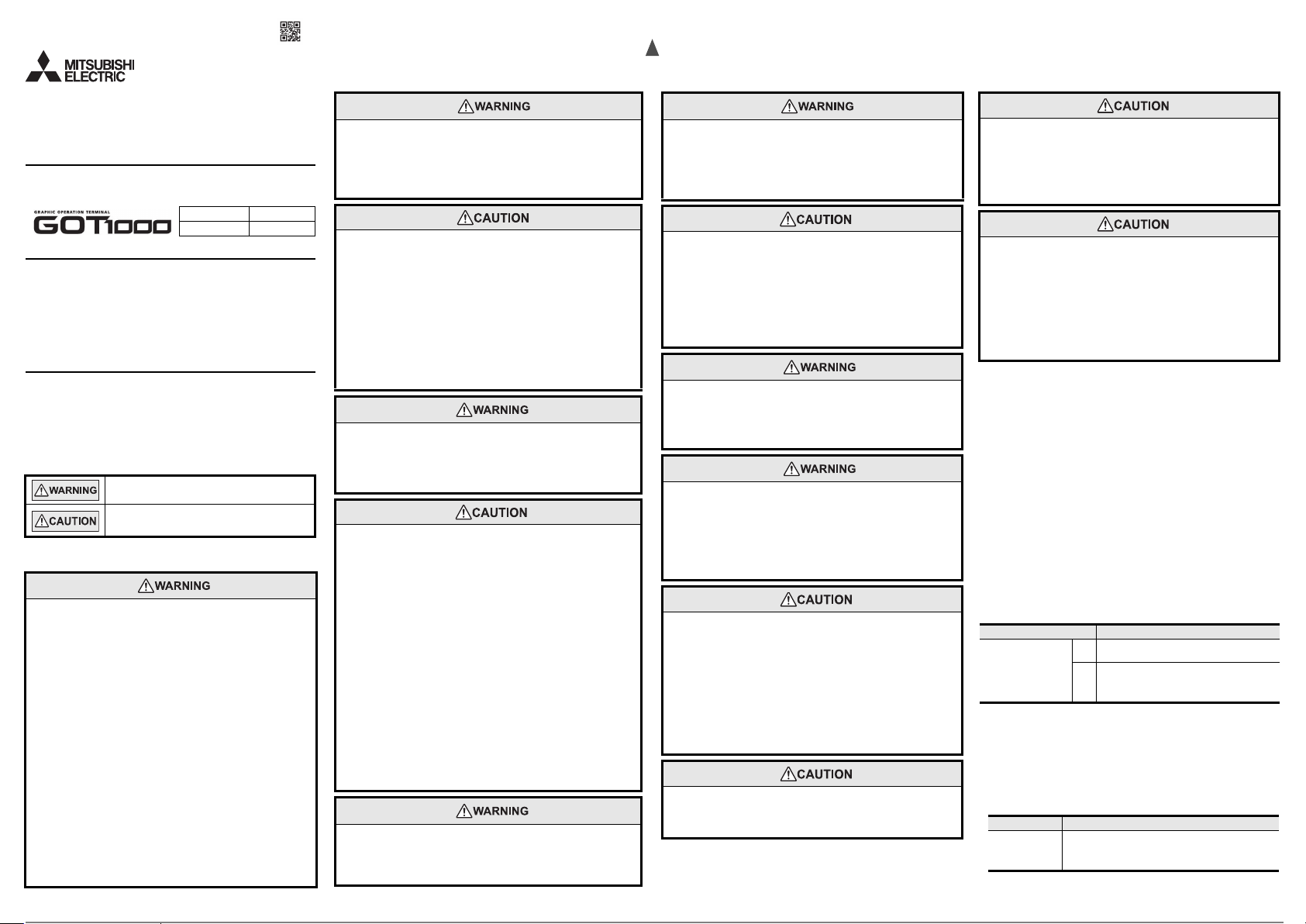
3) General notes on Power supply
The Connector Conversion Box requires an
additional ferrite filter to be attached to the 24V
DC power supply cables. The filter should be
attached in a similar manner as shown in the
figure opposite, i.e. the power cables are
wrapped around the filter. However, as with all
EMC situations the more correctly applied
precautions the better the systems Electromagnetic Compatibility. The ferrite
recommended is a TDK ZCAT3035-1330 or
similar. The ferrite should be placed as near to
the 24V DC terminals of the Connector
Conversion Box as possible (which should be
within 75mm of the GOT terminal).
Associated Manuals
The following manuals are relevant to this product. When these loose manuals are
required, please consult with our local distributor.
Manual name Contents
GT Designer3 Version1
Screen Design Manual
(For GOT1000 Series)
(Fundamentals)
(sold separately)
GT Designer3 Version1
Screen Design Manual
(For GOT1000 Series)
(Functions) 1/2, 2/2
(sold separately)
GT16 Handy GOT User’s
Manual
(Hardware/Utility,
Connection) 1/2, 2/2
(sold separately)
*1 The manual in PDF-format is included in the GT Works3/GT Designer3
products.
Describes methods of the GT
Designer3 installation operation,
basic operation for drawing and
transmitting data to GOT1000
*1
series
Describes specifications and
settings of the object functions
used in GT Designer3
*1
Describes the Handy GOT
hardware-relevant content such as
part names, external dimensions,
mounting, power supply wiring,
specifications, and introduction to
option devices
TDK
Up to 75mm
(2.95inch)
Manual Number
(Model Code)
SH-080866ENG
(1D7MB9)
SH-080867ENG
(1D7MC1)
JY997D41201
JY997D41202
(09R821)
For details of a PLC to be connected, refer to the PLC user's manual respectively.
Bundled Items
Product
Operation switch name character sheets
1) OHP sheet
2) Reference dimension sheet (switch name chan ge sheet
Selector switch keys 2
GT16 Handy GOT General Description (This manual) 1
Model Name Specifications
Name
GOT GT1665HS-VTBD
[640 480 dots], TFT color (65536 colors), built-in
battery
Bundled item Quantity
mount)
1) One sheet
2) One sheet
1. Features
1) Improved monitoring performance and connectivity to FA devices
- A fine and beautiful full-color display which shows even small characters
clearly, is enabled by adopting the high intensity, wide viewing angle and high
definition TFT color LCD. (Also compatible with digital screen displays with
65536 colors, BMP, etc.)
- H igh speed monitoring through high speed communication at maximum of
115.2kbps.
- Mul tiple languages are displayed using the Unicode2.1-compatible fonts and
beautiful characters are drawn using the TrueType and high quality fonts.
- H igh speed display and high speed touch switch response.
2) More efficient GOT operations including screen design, startup, adjustment,
management and maintenance works
- T he display screen of the display unit is created using a drawing software for
PC (GT Designer3 Ver1.14Q or later).
- The 15MB user memory is included as standard.
- C F card interface is included as standard.
- The U SB interface (host/device) is included as standard.
- T he Ethernet interface is included as standard.
3) Enhanced support of FA device setup tools
- Transferring or monitoring the sequence programs using the persona l
computer connected to GOT is available, during direct connection to A, QnA,
L, Q, or FX series PLC CPU (FA Transparent function).
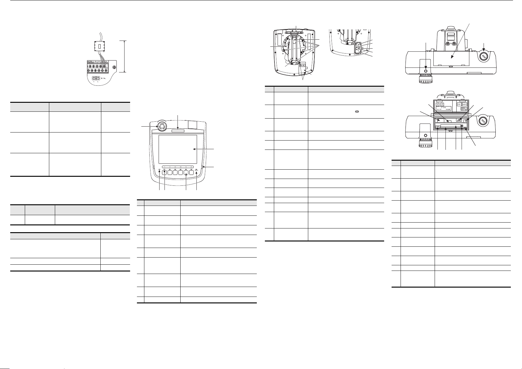
2. Part Name
2.1 Front Panel
(9)
(5)
(1)(2)
(4)
Operation switch name sheet
(prepared by the user)
installation example
(6) (7) (3)
No Name Specifications
(1) Display section
(2) Touch panel
Operation switch
(3)
(6 switches)
Operation switch name
(4)
sheet installation place
(5) Emergency stop switch
(6) POWER LED
Display LED for
(7)
operation switch
(6 LEDs)
Display LED for grip
(8)
switch
(9) Logo label Removable
For the PC connection, refer to the following.
(8)
Displays the utility screen and the us er creation
screen.
For touch switch operation on the util ity screen and
the user creation screen.
Switch for external direct wiring
(independent contact)
Place (concave shape) where the operation switch
name sheet (Insert into the space from a transverse
direction) is installed.
Switch for external direct wiring
(independent contact)
Lit in green: Power is correctly supplied.
Lit in orange: Screen saving and backlight not lit.
Blinks in orange/green: Blown back light bulb.
Not lit: Power is not supplied.
Display LED for operation switch (green)
(lighting control from display section)
Display LED for grip switch (green)
(lighting control from display section)
GT16 Handy GOT User’s Manual
2.2 Back Panel
Environmental protection
back cover closed
(7)
(4)
(1)
(3)
No Name Specifications
External interface
(1)
connector
Environmental
(2)
protection back cover
Environmental
(3)
protection back cover
screw
Hook for hanging on
(4)
walls
(5) Hand strap
Grip angle changing
(6)
screw
(7) Grip switch
(8) Battery
Connector for battery
(9)
connection
(10) RS-232 connector Connector for PLC communication using RS-232
RS-422/485
(11)
connector
Cable connector for
(12)
PLC communication
Terminating resistor
(13)
setting switch
For the connection to the controller, microcomputer board or PC, refer to the
following.
Environmental protection
back cover opened
(5)
(6)
(2)
For external connection cable conne ction (for PLC,
switch and power supply external wiring)
(connector: square 42 pins, male)
Opened and closed when the PLC communication
type is changed (RS-422/485 RS-232, before
shipping: RS-422/485), or the battery is replaced.
For opening and closing the env ironmental
protection back cover (drop prevention screw)
Hook when the Handy GOT is used hanging on
walls.
Used to hold the Handy GOT in h and by putting a
hand under the strap. Length adjustable.
Used when changing the angle of the grip.
(5, M4 screw)
The angle of the grip can be set either to the
standard angle (as before shipping) or 15 degrees
to the right.
Switch for external direct wiring
(independent contact)
For storing clock data, maintenance timing
notification and system log data
(10)
(11)(12)
(13)
(9)
(8)
For battery connection
Connector for PLC communication using RS-422/
485
Interface cable connector for PLC communication
Connector for either (10) or (11) and for selection of
the PLC communication type.
(Connected to RS-422/485 before shipping.)
For switching the RS-422/485 communication
interface terminating resistor (Set to "Disable"
before shipping)
GT16 Handy GOT User’s Manual
2.3 Top Face (Interface)
Interface environmental protection cover closed
(2)
(1)
Interface environmental protection cover opened
(8)
(9)
(4)
(7) (5)
(11)
LED2 LED1
(6) (12)
No Name Specifications
Emergency stop
(1)
switch guard cover
installing hole
Interface
(2)
environmental
protection cover
Keylock switch
(3)
(2-position switch)
CF card access
(4)
switch
(5) CF card interface
Threaded hole for mounting the GT16H-60ESCOV
type emergency stop switch guard (option) (M3)
Opened and closed when using the USB port,
S.MODE switch and reset switch, as well as when
inserting the CF card.
Switch for external direct wiring
(independent contact)
Prohibits accessing the CF card before removing
the card from the Handy GOT.
(OFF before shipping.)
Connector for mounting the CF card (compact flash
card) to the Handy GOT
(6) CF card eject button CF card removal button
(7) CF card access LED
USB interface
(8)
(Device)
(9) USB interface (Host)
S.MODE switch
(10)
(OS install switch)
Lit in green : CF card being accessed.
Not lit: CF card not accessed.
For PC connection (connector type: Mini-B)
For data transfer, data storage
(connector type: TYPE-A)
Switch used for OS installation at GOT startup.
(11) Reset switch Switch for resetting the hardware
Ethernet
(12)
communication status
LED
LED1: Turns on in green during 100Mbps
transmission,
LED2: Turns on in green during data
communication.
(3)
(10)
 Loading...