

Mitsubishi Electric GT15V-75V4R1, GT15V-75V4, GT15V-75R1 User Manual
MODEL GT15V-75V4R1 Video/RGB Input Unit
MODEL
MODEL
GT15V-75V4 Video Input Unit
GT15V-75R1 RGB Input Unit
User's Manual
Thank you for choosing Mitsubishi Electric Graphic Operation Terminal (GOT).
Prior to use, please read both this manual and detailed manual
thoroughly to fully understand the product.
MODEL GT15V-75V4R1-U
MODEL
CODE
IB(NA)-0800348-G(1706)MEE
1D7M54
SAFETY PRECAUTIONS
WARNING
CAUTION
(Always read these precautions before using this equipment.)
Before using this product, please read this manual and the relevant manuals
introduced in this manual carefully and pay full attention to safety to handle the
product correctly.
The precautions given in this manual are concerned with this product. In this
manual, the safety precautions are ranked as "WARNING" and "CAUTION".
Indicates that incorrect handling may cause hazardous
conditions, resulting in death or severe injury.
Indicates that incorrect handling may cause hazardous
conditions, resulting in medium or slight personal
injury or physical damage.
Note that the caution level may lead to a serious accident according to the
circumstances. Always follow the instructions of both levels because they are
important to personal safety.
Please save this manual to make it accessible when required and always forward
it to the end user.
A-1
[DESIGN PRECAUTIONS]
CAUTION
WARNIN G
CAUTION
Do not bunch the control wires or communication cables with the main circuit
or power wires, or lay them close to each other.
As a guide, separate the lines by a distance of at least 100mm (3.94 inches)
otherwise malfunctions may occur due to noise.
[MOUNTING PRECAUTIONS]
Be sure to shut off all phases of the external power supply used by the system
before mounting or removing this unit onto/from the GOT.
Not doing so can cause the unit to fail or malfunction.
Use this unit in the environment that satisfies the general specifications
described in the User's Manual for the GOT used.
Not doing so can cause an electric shock, fire, malfunction or product damage
or deterioration.
Tighten the mounting screws within the specified torque range.
Undertightening can cause the GOT to drop, short circuit or malfunction.
Overtightening can cause a drop, short circuit or malfunction due to the
damage of the screws or the GOT.
Do not touch the conductive and electronic parts of the unit directly.
Doing so can cause a unit malfunction or failure.
A-2
[WIRING PRECAUTIONS]
WARNIN G
CAUTION
Be sure to shut off all phases of the external power supply used by the system
before wiring.
Failure to do so may result in an electric shock, product damage or
malfunctions.
Exercise care to avoid foreign matter such as chips and wire offcuts entering
the GOT. Not doing so can cause a fire, failure or malfunction.
Make sure to securely connect the cable to the connector of unit.
Incorrect connection may cause malfunctions.
Do not hold the cable by hand and pull it out from the unit.
When removing the cable from the unit, make sure to hold the connector by
hand and pull it.
Failure to do so may cause malfunctions or damage to the unit or cable.
Solder the coaxial cable connector correctly.
Incomplete soldering may cause a malfunction.
A-3
[STARTUP/MAINTENANCE PRECAUTIONS]
WARNIN G
CAUTION
CAUTION
CAUTION
When power is on, do not touch the terminals.
Doing so can cause an electric shock or malfunction.
Before starting cleaning, always shut off GOT power externally in all phases.
Not doing so can cause a unit failure or malfunction.
Undertightening can cause a short circuit or malfunction.
Overtightening can cause a short circuit or malfunction due to the damage of
the screws or unit.
Do not disassemble or modify the unit.
Doing so can cause a failure, malfunction, injury or fire.
Do not drop the module or subject it to strong shock.
A module damage may result.
Before touching the unit, always touch grounded metal, etc. to discharge static
electricity from human body, etc.
Not doing so can cause the unit to fail or malfunction.
[DISPOSAL PRECAUTIONS]
When disposing of the product, handle it as industrial waste.
[TRANSPORTATION PRECAUTIONS]
Make sure to transport the GOT main unit and/or relevant unit(s) in the
manner they will not be exposed to the impact exceeding the impact
resistance described in the general specifications of the User's Manual for the
GOT used, as they are precision devices.
Failure to do so may cause the unit to fail.
Check if the unit operates correctly after transportation.
A-4
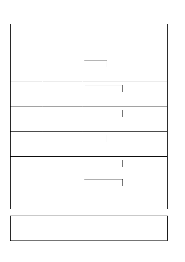
REVISIONS
Partial addition
Addition
Partial corrections
Partial corrections
Addition
Partial corrections
Partial corrections
* The manual number is noted at the lower right of the top cover.
Print Date *Manual Number Revision
Mar., 2006 IB(NA)-0800348-A First edition
Feb., 2007 IB(NA)-0800348-B
Chapter1, Section 2.4.1
Compliance with the EMC and Low
Voltage Directives
Jul., 2007 IB(NA)-0800348-C
Compliance with the EMC and Low
Voltage Directives, Chapter 2, 3, 4
Jun., 2009 IB(NA)-0800348-D
Compliance with the EMC and Low
Voltage Directives
Jun., 2011 IB(NA)-0800348-E
Compliance with the Radio Waves Act
(South Korea)
May, 2015 IB(NA)-0800348-F
Cover
Jun., 2017 IB(NA)-0800348-G
Cover
This manual confers no industrial property rights or any rights of any other kind,
nor does it confer any patent licenses. Mitsubishi Electric Corporation cannot be
held responsible for any problems involving industrial property rights which may
occur as a result of using the contents noted in this manual.
© 2006 MITSUBISHI ELECTRIC CORPORATION
A-5

CONTENTS
1. OVERVIEW .................................................................................................... 1
2. SPECIFICATIONS ......................................................................................... 4
2.1 Video input unit specifications .................................................................4
2.2 RGB input unit specifications ...................................................................5
2.3 Video/RGB input unit specifications ........................................................6
2.4 Cable specifications ................................................................................. 7
2.4.1 Specifications of the cables (coaxial cables) used when
displaying video images .................................................................. 7
2.4.2 Specifications of the cables (9-core combined cables) used
when displaying RGB screens ...................................................... 10
3. PART NAMES AND EXTERNAL DIMENSIONS ......................................... 11
3.1 Part names and external dimensions of the video input unit ................. 11
3.2 Part names and external dimensions of the RGB input unit ..................12
3.3 Part names and external dimensions of the video/RGB input unit ........ 13
3.4 External dimensions of the extension interface relay board .................. 14
4. INSTALLATION PROCEDURE ................................................................... 15
A-6
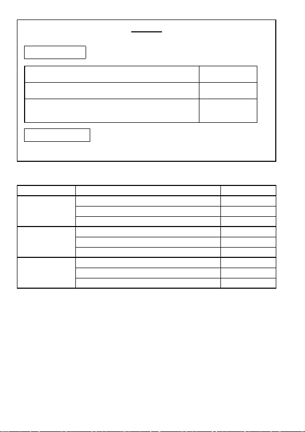
Packing List
Manuals
The following shows manuals relevant to this product.
For relevant manuals, refer to the PDF manuals stored in the DVD-ROM for the drawing
software used.
Detailed Manual
Manual name
Manual number
(Model code)
GT15 User's Manual
(Sold separately)
SH-080528ENG
(1D7M23)
GOT1000 Series Connection Manual (Microcomputer,
MODBUS Products, Peripherals) for GT Works3
(Sold separately)
SH-080871ENG
(1D7MC5)
Relevant Manuals
The following items are included.
Model Product Quantity
Video input unit 1
GT15V-75V4
GT15V-75R1
GT15V-75V4R1
Compliance with the EMC and Low Voltage Directives
To configure a system meeting the requirements of the EMC and Low Voltage Directives
when incorporating the Mitsubishi GOT (EMC and Low Voltage Directives compliant) into
other machinery or equipment, refer to "EMC AND LOW VOLTAGE DIRECTIVES" of the
General Description included with the GOT used.
The CE mark, indicating compliance with the EMC and Low Voltage Directives, is printed on
the rating plate of the GOT.
Mounting screw set (2 screws,2 stickers) 2
Extend interface relay board 1
RGB input unit 1
Mounting screw set (2 screws,2 stickers) 2
Extend interface relay board 1
Video/RGB input unit 1
Mounting screw set (2 screws,2 stickers) 2
Extend interface relay board 1
A-7
 Loading...