


This product was jointly developed and manufactured by
Mitsubishi and Anywire Corporation.
*Note that the warranty on this product differs from that on other
programmable controller products.
(Refer to “WARRANTY” in this manual.)
FX3U-128ASL-M
USER'S MANUAL
AnyWireASLINK


Safety Precautions
(Read these precautions before use.)
PRECAUTIONS REGARDING WARRANTY AND
SPECIFICATIONS
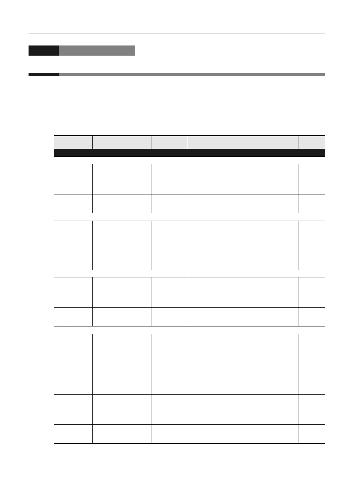
The FX3U-128ASL-M are jointly developed and manufactured by Mitsubishi and Anywire Corporation.
Note that there are some precautions regarding warranty and specifications of this product.
<Warranty>
Other programmable controller
Item FX3U-128ASL-M
Repair term after discontinuation
of production
<Application of the EMC Directive>
Item FX3U-128ASL-M
Applicable EMC standard EN61131-2 (Zone A) EN61131-2
1 year 7 years
Other programmable controller
products
(e.g. MELSEC-F series)
products
(e.g. MELSEC-F series)
<Application of the UL/cUL standards>
Other programmable controller
Item FX3U-128ASL-M
Applicable UL standard/
cUL standard
*1. December 2014 and later. The UL/cUL mark is indicated on the nameplate of the applicable product.
UL508
*1
products
(e.g. MELSEC-F series)
UL508
(1)

Safety Precautions
(Read these precautions before use.)
Before installation, operation, maintenance or inspection of this product, thoroughly read through and
understand this manual and all of the associated manuals. Also, take care to handle the module properly and
safely.
This manual classifies the safety precautions into two categories: and .
Indicates that incorrect handling may cause hazardous conditions, resulting in death or severe
injury.
Indicates that incorrect handling may cause hazardous conditions, resulting in medium or slight
personal injury or physical damage.
Depending on the circumstances, procedures indicated by may also cause severe injury.
It is important to follow all precautions for personal safety.
Store this manual in a safe place so that it can be taken out and read whenever necessary. Always forward it
to the end user.
1. DESIGN PRECAUTIONS
Reference
• An AnyWireASLINK system has no control function for ensuring safety.
• When a communication failure occurs in the network, data in the master block are held.
Check the communication status information and configure an interlock circuit in the sequence program to ensure
that the entire system will operate safely.
• Make sure to have the following safety circuits outside of the PLC to ensure safe system operation even during
external power supply problems or PLC failure.
Otherwise, malfunctions may cause serious accidents.
1) Most importantly, have the following: an emergency stop circuit, a protection circuit, an interlock circuit for
opposite movements (such as normal vs. reverse rotation), and an interlock circuit (to prevent damage to the
equipment at the upper and lower positioning limits).
2) Note that when the PLC CPU detects an error, such as a watchdog timer error, during self-diagnosis, all outputs
are turned off. Also, when an error that cannot be detected by the PLC CPU occurs in an input/output control
block, output control may be disabled.
External circuits and mechanisms should be designed to ensure safe machinery operation in such a case.
15
• Configure safety circuits, such as an emergency stop circuit and interlock circuit, external to the AnyWireASLINK
system.
• Install module so that excessive force will not be applied to the terminal blocks.
Failure to do so may result in wire damage/breakage or PLC failure.
• When executing control (data changes) to an operating PLC, construct an interlock circuit in the sequence program
so that the entire system operates conservatively. Additionally, when executing control such as program changes
and operation status changes (status control) to an operating PLC, thoroughly read the manual and sufficiently
confirm safety in advance.
2. INSTALLATION PRECAUTIONS
• Make sure to cut off all phases of the power supply externally before attempting installation work.
Failure to do so may cause electric shock.
Reference
15
Reference
30
(2)

Safety Precautions
(Read these precautions before use.)
• Use the product within the generic environment specifications described in PLC main unit manual (Hardware
Edition).
Never use the product in areas with excessive dust, oily smoke, conductive dusts, corrosive gas (salt air, Cl2, H2S,
SO2 or NO2), flammable gas, vibration or impacts, or expose it to high temperature, condensation, or rain and wind.
If the product is used in such conditions, electric shock, fire, malfunctions, deterioration or damage may occur.
• Do not touch the conductive parts of the product directly.
Doing so may cause device failures or malfunctions.
• Install the product securely using a DIN rail or mounting screws.
• Install the product on a flat surface. If the mounting surface is rough, undue force will be applied to the PC board,
thereby causing nonconformities.
• When drilling screw holes or wiring, make sure that cutting and wiring debris do not enter the ventilation slits.
Failure to do so may cause fire, equipment failures or malfunctions.
• Be sure to remove the dust proof sheet from the PLC's ventilation slits when installation work is completed.
Failure to do so may cause fire, equipment failures or malfunctions.
• Make sure to attach the top cover, offered as an accessory, before turning on the power or initiating operation after
installation or wiring work.
Failure to do so may cause electric shock.
• Connect extension cables securely to their designated connectors.
Loose connections may cause malfunctions.
3. WIRING PRECAUTIONS
Reference
30
Reference
• Make sure to cut off all phases of the power supply externally before attempting wiring work.
Failure to do so may cause electric shock or damage to the product.
• Connect the DC power supply wiring to the dedicated terminals described in this manual.
If an AC power supply is connected to a DC input/output terminal or DC power supply terminal, the PLC will burn
out.
• Make sure to attach the top cover, offered as an accessory, before turning on the power or initiating operation after
installation or wiring work.
Failure to do so may cause electric shock.
• When drilling screw holes or wiring, make sure that cutting and wiring debris do not enter the ventilation slits.
Failure to do so may cause fire, equipment failures or malfunctions.
• Make sure to properly wire to the terminal block (European type) in accordance with the following precautions.
Failure to do so may cause electric shock, equipment failures, a short-circuit, wire breakage, malfunctions, or
damage to the product.
- The disposal size of the cable end should follow the dimensions described in the manual.
- Tightening torque should follow the specifications in the manual.
- Twist the end of strand wire and make sure that there are no loose wires.
- Do not solder-plate the electric wire ends.
- Do not connect more than the specified number of wires or electric wires of unspecified size.
- Affix the electric wires so that neither the terminal block nor the connected parts are directly stressed.
• Do not apply the 24 V DC power before wiring the entire AnyWireASLINK system.
• Connect a 24 V DC external power supply to FX3U-128ASL-M for the AnyWireASLINK system.
• Make sure to observe the following precautions in order to prevent any damage to the machinery or accidents due
to abnormal data written to the PLC under the influence of noise:
1) Do not bundle the main circuit line together with or lay it close to the main circuit, high-voltage line or load line.
Otherwise, noise disturbance and/or surge induction are likely to take place. As a guideline, lay the control line
at least 100mm (3.94") or more away from the main circuit or high-voltage lines.
2) Ground the shield wire or shield of the shielded cable at one point on the PLC. However, do not use common
grounding with heavy electrical systems.
• Place the cables in a duct or clamp them.
If not, dangling cable may swing or inadvertently be pulled, resulting in damage to the module or cables or
malfunction due to poor contact.
• When disconnecting the cable from the module, do not pull the cable by the cable part.
For the cable connected to the terminal block, loosen the terminal screw.
Pulling the cable connected to the module may result in malfunction or damage to the module or cable.
33
Reference
33
(3)

Safety Precautions
(Read these precautions before use.)
4. STARTUP AND MAINTENANCE PRECAUTIONS
• Do not touch any terminal while the PLC's power is on.
Doing so may cause electric shock or malfunctions.
• Before cleaning or retightening terminals, cut off all phases of the power supply externally.
Failure to do so may cause electric shock.
• Before modifying or disrupting the program in operation or running the PLC, carefully read through this manual and
the associated manuals and ensure the safety of the operation.
An operation error may damage the machinery or cause accidents.
• Do not disassemble or modify the PLC.
Doing so may cause fire, equipment failures, or malfunctions.
For repair, contact your local Mitsubishi Electric representative.
• Turn off the power to the PLC before connecting or disconnecting any extension cable.
Failure to do so may cause equipment failures or malfunctions.
• Turn off the power to the PLC before attaching or detaching the following devices.
Failure to do so may cause equipment failures or malfunctions.
- Peripheral devices, display module, expansion boards, and special adapters
- Input/output extension units/blocks, FX Series terminal blocks, and the special function units/blocks
- Battery and memory cassette
5. DISPOSAL PRECAUTIONS
Reference
71
Reference
71
• Please contact a certified electronic waste disposal company for the environmentally safe recycling and disposal of
your device.
6. TRANSPORTATION AND STORAGE PRECAUTIONS
• The PLC is a precision instrument. During transportation, avoid impacts larger than those specified in the general
specifications of the PLC main unit manual by using dedicated packaging boxes and shock-absorbing palettes.
Failure to do so may cause failures in the PLC.
After transportation, verify operation of the PLC and check for damage of the mounting part, etc.
Reference
15
Reference
15
(4)

FX3U-128ASL-M User's Manual
FX3U-128ASL-M
User’s Manual
Manual number JY997D52101
Manual revision E
Date 3/2018
Foreword
This manual describes the FX3U-128ASL-M AnyWireASLINK system master block and should be read and
understood before attempting to install or operate the hardware.
Store this manual in a safe place so that you can take it out and read it whenever necessary. Always forward
it to the end user.
This manual confers no industrial property rights or any rights of any other kind, nor does it confer any patent licenses. Mitsubishi
Electric Corporation cannot be held responsible for any problems involving industrial property rights which may occur as a result of
using the contents noted in this manual.
© 2013 MITSUBISHI ELECTRIC CORPORATION
1

FX3U-128ASL-M User's Manual
Outline Precautions
• This manual provides information for the use of the FX3U-128ASL-M type AnyWireASLINK system master
block.
The manual has been written to be used by trained and competent personnel. The definition of such a
person or persons is as follows;
1) Any engineer who is responsible for the planning, design and construction of automatic equipment using
the product associated with this manual should be of a competent nature, trained and qualified to the
local and national standards required to fulfill that role. These engineers should be fully aware of all
aspects of safety with aspects regarding to automated equipment.
2) Any commissioning or maintenance engineer must be of a competent nature, trained and qualified to the
local and national standards required to fulfill the job. These engineers should also be trained in the use
and maintenance of the completed product. This includes being familiar with all associated manuals and
documentation for the product. All maintenance should be carried out in accordance with established
safety practices.
3) All operators of the completed equipment should be trained to use that product in a safe and coordinated
manner in compliance with established safety practices. The operators should also be familiar with
documentation that is connected with the actual operation of the completed equipment.
Note: the term 'completed equipment' refers to a third party constructed device that contains or uses the
product associated with this manual.
• This product has been manufactured as a general-purpose part for general industries, and has not been
designed or manufactured to be incorporated in a device or system used in purposes related to human life.
• Before using the product for special purposes such as nuclear power, electric power, aerospace, medicine
or passenger movement vehicles, consult with Mitsubishi Electric.
• This product has been manufactured under strict quality control. However when installing the product
where major accidents or losses could occur if the product fails, install appropriate backup or failsafe
functions into the system.
• When combining this product with other products, please confirm the standards and codes of regulation to
which the user should follow. Moreover, please confirm the compatibility of this product with the system,
machines, and apparatuses to be used.
• If there is doubt at any stage during installation of the product, always consult a professional electrical
engineer who is qualified and trained in the local and national standards. If there is doubt about the
operation or use, please consult your local Mitsubishi Electric representative.
• Since the examples within this manual, technical bulletin, catalog, etc. are used as reference; please use it
after confirming the function and safety of the equipment and system. Mitsubishi Electric will not accept
responsibility for actual use of the product based on these illustrative examples.
• The content, specification etc. of this manual may be changed for improvement without notice.
• The information in this manual has been carefully checked and is believed to be accurate; however, if you
notice any doubtful point, error, etc., please contact your local Mitsubishi Electric representative.
Registration
• Anywire and ANYWIREASLINK is a trademark of Anywire Corporation.
• The company name and the product name to be described in this manual are the registered trademarks or
trademarks of each company.
2

FX3U-128ASL-M User's Manual
Table of Contents
SAFETY PRECAUTIONS ..................................................................................................(1)
Standards................................................................................................................................... 6
Certification of UL, cUL standards ....................................................................................................... 6
Compliance with EC directive (CE Marking) ........................................................................................ 6
Associated Manuals.................................................................................................................. 8
Generic Names and Abbreviations Used in the Manual ...................................................... 10
Reading the Manual ................................................................................................................ 11
1. Introduction 12
1.1 Outline........................................................................................................................................... 12
1.1.1 Outline and features of AnyWireASLINK system .......................................................................... 12
1.2 External Dimensions and Part Names .......................................................................................... 13
1.3 Indications of LEDs ....................................................................................................................... 13
1.4 Terminal Layout ............................................................................................................................14
2. Specification 15
Table of Contents
2.1 General Specifications .................................................................................................................. 16
2.2 Power Supply Specification........................................................................................................... 16
2.3 Performance Specifications .......................................................................................................... 17
2.4 Communication Specifications ...................................................................................................... 18
2.4.1 Transmission cycle time ................................................................................................................ 18
2.4.2 Double check................................................................................................................................. 20
2.4.3 Response delay time .....................................................................................................................21
2.4.4 Connection of slave modules ........................................................................................................ 23
3. System Configuration 24
3.1 General Configuration ................................................................................................................... 24
3.2 Applicable PLC.............................................................................................................................. 25
3.3 Connection with PLC..................................................................................................................... 25
3.4 About allocation of system-wide remote I/O.................................................................................. 26
3.5 Number of transmission points setting .......................................................................................... 27
3.6 Automatic address detection......................................................................................................... 28
3.7 Start-up procedure of the system.................................................................................................. 29
4. Installation 30
4.1 DIN rail mounting .......................................................................................................................... 31
4.2 Direct mounting ............................................................................................................................. 32
5. Wiring, Power-ON/OFF Timing 33
5.1 AnyWireASLINK connection terminal block .................................................................................. 34
5.2 Cable treatment............................................................................................................................. 34
5.3 Wiring precautions ........................................................................................................................34
5.4 Power supply and grounding wiring .............................................................................................. 35
5.4.1 Power supply and grounding wiring...............................................................................................35
5.4.2 Grounding...................................................................................................................................... 35
5.5 Power supply details to the AnyWireASLINK system ................................................................... 36
3

FX3U-128ASL-M User's Manual
5.6 Power-ON/OFF timing................................................................................................................... 39
6. Introduction of Functions 40
6.1 Functions List ................................................................................................................................ 40
6.2 Details of functions........................................................................................................................ 40
6.2.1 Bit transmission function................................................................................................................ 40
6.2.2 Parameter reading/writing function................................................................................................ 41
6.2.3 Automatic address detection function............................................................................................ 44
6.2.4 Automatic Reading of the System Configuration........................................................................... 45
6.2.5 Transmission cable short detection function .................................................................................46
6.2.6 Disconnected transmission cable location detection function ....................................................... 47
6.2.7 Transmission cable voltage drop detection function...................................................................... 48
6.2.8 Parameter access error detection function.................................................................................... 49
6.2.9 Same ID used detection function................................................................................................... 51
6.2.10 Module with no ID setting detection function ............................................................................... 52
7. Buffer Memory 53
7.1 How to Read/Write from/to Buffer Memory ................................................................................... 53
7.1.1 Direct specification of buffer memory ............................................................................................ 53
7.1.2 FROM/TO instructions...................................................................................................................53
7.2 Buffer Memory List ........................................................................................................................ 54
7.3 Details of buffer memory ............................................................................................................... 56
7.3.1 [BFM#0 to #7] Input information area............................................................................................ 56
7.3.2 [BFM#27] Data access command ................................................................................................. 56
7.3.3 [BFM#28] Status information.........................................................................................................57
7.3.4 [BFM#29] Error code .....................................................................................................................57
7.3.5 [BFM#30] Model code ................................................................................................................... 59
7.3.6 [BFM#32, #33] Number of I/O points setting value........................................................................ 59
7.3.7 [BFM#34, #35] Number of I/O points whose use is allowed by main unit ..................................... 59
7.3.8 [BFM#4096 to #4103] Output information area ............................................................................. 60
7.3.9 [BFM#8192] Number of the error IDs ............................................................................................ 60
7.3.10 [BFM#8193 to #8320] Error ID information storage areas........................................................... 60
7.3.11 [BFM#8960] Number of the connected modules.........................................................................61
7.3.12 [BFM#9216] Number of IDs of connected modules..................................................................... 61
7.3.13 [BFM#9217 to #9344] Connected module ID information storage areas .................................... 61
7.3.14 [BFM#9984] Number of the alarm IDs......................................................................................... 61
7.3.15 [BFM#9985 to #10112] Alarm ID information storage areas ....................................................... 61
7.3.16 [BFM#10257] Latest error ID storage area.................................................................................. 62
7.3.17 [BFM#10320] Parameter access method setting ........................................................................ 62
7.3.18 [BFM#10321] Parameter access target module ID specification................................................. 62
7.3.19 [BFM#10496 to #10623, #11008 to #11135] Parameter storage location memory number........ 63
7.3.20 [BFM#12288 to #18431] Parameter storage areas ..................................................................... 64
Table of Contents
8. Program Examples 67
8.1 Basic Program Example................................................................................................................ 67
8.2 Error Flag Clear Command Output Program Example .................................................................69
8.3 Automatic Address Detection Command Output Program Example............................................. 70
9. Troubleshooting 71
9.1 LED Diagnosis of 128ASL-M ........................................................................................................ 72
9.2 Error Codes................................................................................................................................... 74
4

FX3U-128ASL-M User's Manual
9.3 Diagnostics on the PLC Main Unit ................................................................................................ 76
9.3.1 POWER (POW) LED [ON/Flicker/OFF].........................................................................................76
9.3.2 ALM LED, BATT (BAT) LED [ON/OFF].........................................................................................76
9.3.3 ERROR (ERR) LED [ON/Flicker/OFF] .......................................................................................... 77
9.4 Diagnostics by GX Works2 ........................................................................................................... 77
Appendix A: Version Information 79
Appendix A-1 Version check method.......................................................................................... 79
Appendix A-2 Version upgrade history ....................................................................................... 79
Warranty................................................................................................................................... 81
Revised History ....................................................................................................................... 82
Table of Contents
5

FX3U-128ASL-M User's Manual
Standards
Certification of UL, cUL standards
FX3U-128ASL-M units comply with the UL standards (UL, cUL). (December 2014 and later)
UL, cUL File number :E95239
Regarding the standards that comply with the main unit, please refer to either the FX series product catalog or
consult with your nearest Mitsubishi product provider.
Compliance with EC directive (CE Marking)
This document does not guarantee that a mechanical system including this product will comply with the
following standards.
Compliance to EMC directive and LVD directive for the entire mechanical module should be checked by the
user/manufacturer. For more information please consult with your nearest Mitsubishi product provider.
Regarding the standards that comply with the main unit, please refer to either the FX series product catalog or
consult with your nearest Mitsubishi product provider.
Regarding the standards that comply with the AnyWireASLINK slave module, please consult with Anywire
Corporation.
Standards
Requirement for Compliance with EMC directive
The following products have shown compliance through direct testing (of the identified standards below) and
design analysis (through the creation of a technical construction file) to the European Directive for
Electromagnetic Compatibility (2014/30/EU) when used as directed by the appropriate documentation.
Attention
This product is designed for use in industrial applications.
Type: Programmable Controller (Open Type Equipment)
Models: MELSEC FX
from October 1st, 2013 FX
EN61131-2: 2007
Programmable controllers
- Equipment requirements and tests
3U series manufactured
3U-128ASL-M
Standard Remark
Compliance with all relevant aspects of the standard.
EMI
• Radiated Emission
• Conducted Emission
EMS
• Radiated electromagnetic field
• Fast transient burst
• Electrostatic discharge
• High-energy surge
• Voltage drops and interruptions
• Conducted RF
• Power frequency magnetic field
6

FX3U-128ASL-M User's Manual
Shielding cover
Shielded cable
Wires
*1
EMI gasket
Caution to conform with EC Directives
• Installation in Enclosure
Programmable logic controllers are open-type devices that must be installed and used within conductive
control cabinets. Please use the programmable logic controller while installed within a conductive shielded
control cabinet. Please secure the cabinet door to the control cabinet (for conduction).
Installation within a control cabinet greatly affects the safety of the system and aids in shielding noise from
the programmable logic controller.
• Control cabinet
- The control cabinet must be conductive.
- Ground the control cabinet with the thickest possible grounding cable.
- To ensure that there is electrical contact between the control cabinet and its door, connect the cabinet
and its doors with thick wires.
- In order to suppress the leakage of radio waves, the control cabinet structure must have minimal
openings. Also, wrap the cable holes with a shielding cover or other shielding devices.
- The gap between the control cabinet and its door must be as small as possible by attaching EMI gaskets
between them.
Standards
*1. These wires are used to improve the conductivity between the door and control cabinet.
• Use the FX
3U-128ASL-M in Zone A
*2
as defined in EN61131-2.
*2. Zone defined in EN61131-2.
Separation defined in EN61131-2 for EMC LVD regulation decided depending on condition in
industrial setting.
Zone C = Factory mains which is isolated from public mains by dedicated transformers.
Zone B = Dedicated power distribution which is protected by secondary surge protection. (300 V or
less in the rated voltage is assumed.)
Zone A = Local power distribution which is isolated from dedicated power distribution by AC/DC
converters, isolation transformers, etc. (120 V or less in the rated voltage is assumed.)
• Please attach a ferrite core less than 200 mm from the FX
3U-128ASL-M side terminal block to the DP and
DN signal wires. The wire should be wound twice around the ferrite core. The ferrite core should be a
product equivalent to ZCAT3035-1330 by TDK Corporation.
• Please attach a noise filter to the 0 V and 24 V power cables. The noise filter should be a product
equivalent to SNR-10-223 by COSEL CO., LTD.
7
FX3U-128ASL-M User's Manual
Associated Manuals
Only the installation manual is packed together with the FX3U-128ASL-M type AnyWireASLINK system
master block.
For a detailed explanation of the FX
manual.
For the hardware information and instructions on the PLC main unit, refer to the respective manuals.
Title of manual
Manual for the Main Module
FX3G Series PLCs Main Unit
Supplied
Manual
Additional
Manual
FX3GC Series PLCs Main Unit
Supplied
Manual
Additional
Manual
FX3U Series PLCs Main Unit
Supplied
Manual
Additional
Manual
FX3UC Series PLCs Main Unit
Supplied
Manual
Supplied
Manual
Supplied
Manual
Additional
Manual
FX3G Series
Hardware Manual
FX3G Series
User’s Manual
- Hardware Edition
FX3GC Series
Hardware Manual
FX3GC Series
User’s Manual
- Hardware Edition
FX3U Series
Hardware Manual
3U Series
FX
User’s Manual
- Hardware Edition
FX3UC (D, DS, DSS) Series
Hardware Manual
FX3UC-32MT-LT-2
Hardware Manual
FX3UC-32MT-LT
Hardware Manual
(Only Japanese document)
FX
3UC Series
User’s Manual
- Hardware Edition
Associated Manuals
3U-128ASL-M type AnyWireASLINK system master block., refer to this
Refer to these manuals
Refer to the appropriate equipment manual
For a detailed explanation, refer to an additional manual
Document
number
JY997D46001
JY997D31301
JY997D45201
JY997D45401
JY997D50301
JY997D16501
JY997D50501
JY997D31601
JY997D12701
JY997D28701
Description
Describes FX3G Series PLC specification for I/O,
wiring and installation extracted from the FX3G User’s
Manual - Hardware Edition.
For details, refer to FX3G Series User’s Manual Hardware Edition.
Describes FX3G Series PLC specification details for
I/O, wiring, installation and maintenance.
Describes FX3GC Series PLC specification for I/O,
wiring and installation extracted from the FX3GC User’s
Manual - Hardware Edition.
For details, refer to FX3GC Series User’s Manual Hardware Edition.
Describes FX3GC Series PLC specification details for
I/O, wiring, installation and maintenance.
Describes FX3U Series PLC specification for I/O,
wiring and installation extracted from the FX3U User’s
Manual - Hardware Edition.
For details, refer to FX3U Series User’s Manual Hardware Edition.
Describes FX
I/O, wiring, installation and maintenance.
Describes FX3UC (D, DS, DSS) Series PLC
specification for I/O, wiring and installation extracted
from the FX
For details, refer to FX
Hardware Edition.
Describes FX3UC-32MT-LT-2 specification for I/O,
wiring and installation extracted from the FX3UC User’s
Manual - Hardware Edition.
For details, refer to FX3UC Series User’s Manual Hardware Edition.
Describes FX3UC-32MT-LT specification for I/O, wiring
and installation extracted from the FX3UC User’s
Manual - Hardware Edition.
For details, refer to FX
Hardware Edition.
Describes FX
I/O, wiring, installation and maintenance.
3U Series PLC specification details for
3UC User’s Manual - Hardware Edition.
3UC Series User’s Manual -
3UC Series User’s Manual -
3UC Series PLC specification details for
Model
code
-
09R521
-
09R533
-
09R516
-
-
-
09R519
8

FX3U-128ASL-M User's Manual
Associated Manuals
Title of manual
Programming
FX3S/FX3G/FX3GC/FX3U/
Additional
Manual
Additional
Manual
Additional
Manual
Additional
Manual
Additional
Manual
Additional
Manual
Additional
Manual
Manuals for FX3U-128ASL-M type AnyWireASLINK system master block
Supplied
Manual
Additional
Manual
FX3UC Series
Programming Manual
- Basic & Applied
Instruction Edition
MELSEC-Q/L/F
Structured Programming
Manual (Fundamentals)
FX CPU Structured
Programming Manual
[Device & Common]
FX CPU Structured
Programming Manual
[Basic & Applied
Instruction]
FX CPU Structured
Programming Manual
[Application Functions]
GX Works2 Version 1
Operating Manual
(Common)
GX Works2 Version 1
Operating Manual
(Intelligent Function Module)
FX3U-128ASL-M
Installation Manual
FX3U-128ASL-M
User’s Manual
(This Manual)
Document
number
JY997D16601
SH-080782
JY997D26001
JY997D34701
JY997D34801
SH-080779ENG
SH-080921ENG
JY997D51901
JY997D52101
Describes FX3S/FX3G/FX3GC/FX3U/FX3UC Series
PLC programming for basic/applied instructions and
devices.
Programming methods, specifications, functions, etc.
required to create structured programs.
Devices, parameters, etc. provided in structured
projects of GX Works2.
Sequence instructions provided in structured projects
of GX Works2.
Application functions provided in structured projects of
GX Works2.
Explains the system configuration of GX Works2 and
the functions common to Simple project and Structured
project such as parameter setting, operation method
for the online function.
Explains operation methods of intelligent function
module such as parameter setting, monitoring
programs, and predefined protocol support function in
GX Works2.
Describes FX3U-128ASL-M type AnyWireASLINK
system master block extracted from the FX3U-128ASL-
M User's Manual.
For details, refer to FX3U-128ASL-M User’s Manual.
Describes FX3U-128ASL-M type AnyWireASLINK
system master block details.
Description
Model
code
09R517
13JW06
09R925
09R926
09R927
13JU63
13JU69
-
09R521
9

FX3U-128ASL-M User's Manual
Generic Names and Abbreviations Used in the Manual
Generic Names and Abbreviations Used in the Manual
Generic name or abbreviation Description
PLC
FX3G series Generic name for FX3G Series PLC
FX3G PLC or main unit Generic name for FX3G Series PLC main unit
FX3GC series Generic name for FX3GC Series PLC
FX3GC PLC or main unit Generic name for FX3GC Series PLC main unit
FX3U series Generic name for FX3U Series PLC
FX3U PLC or main unit Generic name for FX3U Series PLC main unit
FX3UC series Generic name for FX3UC Series PLC
FX3UC PLC or main unit Generic name for FX3UC Series PLC main unit
Generic name for expansion board
Expansion board
Special adapter
I/O extension unit/block
Special function unit/block or
Special extension unit
Special function unit Generic name for special function unit
Special function block Generic name for special function block
128ASL-M Abbreviated name for FX3U-128ASL-M
Memory cassette
FX Series terminal block
Slave module Generic name for AnyWireASLINK slave module
Peripheral unit
Peripheral unit Generic name for programming software, handy programming panel, and indicator
Programming tool
Programming tool Generic name for programming software and handy programming panel
Programming software Generic name for programming software
GX Works2 Abbreviation of programming software packages SWDNC-GXW2-E
Handy programming panel (HPP) Generic name for FX-30P and FX-20P(-E)
Indicators
GOT1000 Series Generic name for GT16, GT15, GT14, GT11 and GT10
Manual
FX3G Hardware Edition Abbreviation of FX3G Series User's Manual - Hardware Edition
FX3GC Hardware Edition Abbreviation of FX3GC Series User's Manual - Hardware Edition
FX3U Hardware Edition Abbreviation of FX3U Series User's Manual - Hardware Edition
FX3UC Hardware Edition Abbreviation of FX3UC Series User's Manual - Hardware Edition
Hardware Edition manual
Programming manual
The number of connectable units, however, depends on the type of main unit.
To check the number of connectable units, refer to the User's Manual - Hardware Edition of the main
unit to be used for your system.
Generic name for high-speed input/output special adapter, communication special adapter, analog
special adapter, and CF card special adapter.
The number of connectable units, however, depends on the type of main unit.
To check the number of connectable units, refer to the User's Manual - Hardware Edition of the main
unit to be used for your system.
Generic name for input/output powered extension unit and input/output extension block
The number of connectable units, however, depends on the type of main unit.
To check the number of connectable units, refer to the User's Manual - Hardware Edition of the main
unit to be used for your system.
Generic name for special function unit and special function block
The number of connectable units, however, depends on the type of main unit.
To check the number of connectable units, refer to the User's Manual - Hardware Edition of the main
unit to be used for your system.
Generic name for Memory cassette
The number of connectable units, however, depends on the type of main unit.
To check the number of connectable units, refer to the User's Manual - Hardware Edition of the main
unit to be used for your system.
Generic name for FX Series terminal block
The number of connectable units, however, depends on the type of main unit.
To check the number of connectable units, refer to the User's Manual - Hardware Edition of the main
unit to be used for your system.
Generic name for User's Manual - Hardware Edition of each of the following Series: FX3G/FX3GC/
FX3U/FX3UC
Abbreviation of FX3S/FX3G/FX3GC/FX3U/FX3UC Series Programming Manual - Basic and Applied
Instructions Edition
10

FX3U-128ASL-M User's Manual
This area shows the title of the chapter and the
title of the section for the current page.
The right side of each page
indexes the chapter number
for the page currently opened.
This area shows the
manual title for the current
page.
The " " mark indicates
a reference destination
and reference manual.
Shows the reference.
Indexes the chapter number.
Shows the title of the chapter and the title
of the section.
Shows the manual title.
Reading the Manual
Reading the Manual
The above is different from the actual page, as it is provided for explanation only.
11

FX3U-128ASL-M User's Manual
1. Introduction
1.1 Outline
The FX3U-128ASL-M type AnyWireASLINK system master block (hereinafter referred to as 128ASL-M) is a
special function block for building an AnyWireASLINK system with FX
The 128ASL-M is jointly developed and manufactured by Mitsubishi and Anywire Corporation.
The AnyWireASLINK system is a sensor network system.
1.1.1 Outline and features of AnyWireASLINK system
AnyWireASLINK is a high-speed and highly reliable system which relieves the work site from complicated and
incorrect wiring.
In this network, sensors at the end of a control system are connected to a programmable controller in the
optimum form.
1) Flexible wiring
The AnyWireASLINK allows flexible connections if the overall cable distance of transmission cables is
within 200m.
There is no restriction about, for example, the main line length, station-to-station distance, and number of
branches.
2) Single-touch cable connection and disconnection
Using a dedicated connector enables cables to be connected and disconnected with a single operation
and eases module addition and replacement.
For writing with the dedicated connectors, contact Anywire Corporation.
3) Space saving
The system needs much less space because of a wide selection of small-type slave modules
(manufactured by Anywire Corporation).
4) RAS improvement
The system start-up time can be reduced by checking whether a slave module is connected or by
detecting an ID setting error.
1 Introduction
1.1 Outline
3G/FX3GC/FX3U/FX3UC PLC.
12

FX3U-128ASL-M User's Manual
[Without top cover]
Unit: mm (inches)
MASS (Weight): Approx. 0.2 kg (0.44 lbs)
[1]
[2]
[3]
[4]
[11]
[5] [8]
[6]
[7]
95.5 (3.76")
87 (3.43")
9 (0.36")
43 (1.7")
4 (0.16")
90 (3.55")
[9]
2-4.5 mounting holes
80 (3.15")(mounting hole pitch)
[10]
1.2 External Dimensions and Part Names
[1] Extension cable [7] DIN rail mounting hook
[2] Direct mounting hole
2 holes of φ4.5 (0.18")
(mounting screw: M4 screw)
[4] Status LEDs (green, red)
→ Refer to Section 1.3.
[6] DIN rail mounting groove (DIN rail: DIN46277,
35 mm (1.38") width)
[8] SET switch
(Automatic address setting switch)
[9] Transmission points number setting switch
(Rotary switch)[3] Power LED (green)
[10] Extension connector
[11] AnyWireASLINK connection terminal block
1 Introduction
1.2 External Dimensions and Part Names
→ Refer to Section 1.4.[5] Nameplate
Configuration
ON/OFF Timing
1
Introduction
2
Specification
3
System
4
Installation
5
Wiring, Power-
1.3 Indications of LEDs
LED
display
POWER
LINK
SET
ALM
Name
Module operation
display
Transmission
display
Address detection
in progress
display
Transmission
alarm display
LED
color
Green
Green
Green
Red
Status Description
ON 5 V DC is being supplied from the PLC.
OFF 5 V DC is not being supplied from the PLC, or they are the units failure.
ON units failure
Flicker Operating normally
OFF 5 V DC power OFF or the units failure.
ON Automatic address detection in progress.
Flicker Writing in the EEPROM
OFF Operating normally
ON DP/DN disconnection
Slow flicker
(one-second intervals)
Fast flicker
(0.2-second intervals)
OFF Operating normally
DP/DN short
24 V DC is not being supplied or the voltage is low.
6
Introduction of
Functions
7
Buffer Memory
8
Program
Examples
9
Troubleshooting
13
A
Version
Information

FX3U-128ASL-M User's Manual
24 V
0 V
DP
DN
LG
1.4 Terminal Layout
Terminal name Description
• AnyWireASLINK connection terminal block specifications
Type: MSTB2,5/5-STF-5,08AU (Phoenix Contact Co., Ltd.)
Electric wire size: 0.2 to 2.5 mm
Tightening torque: 0.5 to 0.6 N•m (For both connector fixing screw and transmission cable connection
screw)
Do not tighten terminal screws with a torque outside the above-mentioned range. Failure to do so may
cause equipment failures or malfunctions.
24 V 24 V terminal for sensor power and communication.
0 V 0 V terminal for sensor power and communication.
DP
DN
LG
Transmission signal (+) terminal. It connects with DP of the slave module and the
Terminator.
Transmission signal (-) terminal. It connects with DN of the slave module and the
Terminator.
Functional earth terminal. The one point is grounded with the grounding terminal and
functional earth terminal of the PLC (FG terminal).
2
(AWG24 to 12)
→ For transmission cable treatment, refer to Section 5.2.
1 Introduction
1.4 Terminal Layout
14

FX3U-128ASL-M User's Manual
2. Specification
DESIGN PRECAUTIONS
• An AnyWireASLINK system has no control function for ensuring safety.
• When a communication failure occurs in the network, data in the master block are held.
Check the communication status information and configure an interlock circuit in the sequence program to ensure that the entire
system will operate safely.
• Make sure to have the following safety circuits outside of the PLC to ensure safe system operation even during external power supply
problems or PLC failure.
Otherwise, malfunctions may cause serious accidents.
1) Most importantly, have the following: an emergency stop circuit, a protection circuit, an interlock circuit for opposite movements
(such as normal vs. reverse rotation), and an interlock circuit (to prevent damage to the equipment at the upper and lower
positioning limits).
2) Note that when the PLC CPU detects an error, such as a watchdog timer error, during self-diagnosis, all outputs are turned off.
Also, when an error that cannot be detected by the PLC CPU occurs in an input/output control block, output control may be
disabled.
External circuits and mechanisms should be designed to ensure safe machinery operation in such a case.
2 Specification
1
Introduction
2
Specification
3
System
Configuration
4
Installation
DESIGN PRECAUTIONS
• Configure safety circuits, such as an emergency stop circuit and interlock circuit, external to the AnyWireASLINK system.
• Install module so that excessive force will not be applied to the terminal blocks.
Failure to do so may result in wire damage/breakage or PLC failure.
• When executing control (data changes) to an operating PLC, construct an interlock circuit in the sequence program so that the entire
system operates conservatively. Additionally, when executing control such as program changes and operation status changes (status
control) to an operating PLC, thoroughly read the manual and sufficiently confirm safety in advance.
DISPOSAL PRECAUTIONS
• Please contact a certified electronic waste disposal company for the environmentally safe recycling and disposal of your device.
TRANSPORTATION AND
STORAGE PRECAUTIONS
• The PLC is a precision instrument. During transportation, avoid impacts larger than those specified in the general specifications of the
PLC main unit manual by using dedicated packaging boxes and shock-absorbing palettes.
Failure to do so may cause failures in the PLC.
After transportation, verify operation of the PLC and check for damage of the mounting part, etc.
5
Wiring, Power-
ON/OFF Timing
6
Introduction of
Functions
7
Buffer Memory
8
Program
Examples
15
9
Troubleshooting
A
Version
Information

FX3U-128ASL-M User's Manual
2.1 General Specifications
Items other than the following are equivalent to those of the PLC main unit.
For general specifications, refer to the Hardware Edition manual of the connected PLC.
Item Specification
Ambient temperature 0 to 55 °C (32 to 131 °F) when operating and -25 to 75 °C (-13 to 167 °F) when stored
Dielectric withstand voltage 500 V AC for one minute
Insulation resistance 5 MΩ or more by 500 V DC Megger
Pollution degree 2 or less
2.2 Power Supply Specification
Item Specification
Driving power supply
External power supply for
ASLINK communication
*1. The 128ASL-M supplies the internal power supply of slave modules and the connection load power
supply of non-isolated slave modules from transmission signals.
The following expression shows the rough value of the transmission cable supply current (A):
Transmission cable supply current = Internal current consumption of slave modules + Maximum
On some slave modules with cables, the cross-sectional area of the integrated transmission cables
(DP, DN) is 0.75mm
sectional area of normal transmission cables (DP, DN) meets the following requirements.
For slave modules with integrated transmission cables (DP, DN), the length of the transmission cables
(DP, DN) is included in the total length.
- Relationship between the total length of the AnyWireASLINK system, the cross-sectional area of
connection cables and transmission cable supply current
Cross-sectional area
of transmission
cables
2
1.25 mm
2
0.75 mm
130 mA / 5 V DC
5 V DC power is supplied internally from the main unit.
Voltage: 21.6 to 27.6 V DC (24 V DC -10% to +15%), ripple voltage 0.5 Vp-p or lower
Rated voltage: 24 V DC
* Please use a UL Class 2 power supply.
Module current consumption: 0.1 A
Transmission cable supply current*1: Up to 2 A
2
or less. However, they can be used without any problem, provided that the cross-
Total length of 50 m or less Total length of 50 m to 100 m Total length of 100 m to 200 m
Up to 2 A Up to 1 A Up to 0.5 A
Up to 1.2 A Up to 0.6 A Up to 0.3 A
2 Specification
2.1 General Specifications
Between PLC all terminals and ground terminal
current consumption of sensors and actuators connected to
non-isolated slave modules
Transmission cable supply current
16
- Quick reference chart of total length (m) and transmission cable supply current (A) (1.25 mm
2
1.0
0.6
0.5
0.4
Transmission cable supply current (A)
0
Total length (m)
20010050 60100 170
2
)

FX3U-128ASL-M User's Manual
- Quick reference chart of total length (m) and transmission cable supply current (A) (0.75 mm2)
2
1.2
0.96
0.6
0.48
Transmission cable supply current (A)
0.3
0.24
0
2 Specification
2.3 Performance Specifications
1
Introduction
2
Specification
3
System
Configuration
4
Installation
20010080400 50 160
Total length (m)
2.3 Performance Specifications
Item Specification
Transmission clock 27.0 kHz
Maximum transmission distance
(total length)
Transmission system DC power supply transmission total frame cyclic system
Connection type Bus topology (multidrop system, T-branch system, tree branch system)
Transmission protocol Dedicated protocol (AnyWireASLINK)
Error control Double-check system, checksum
Number of connected I/O points Up to 128 points
Number of connectable modules Up to 128 (varies depending on the current consumption of each slave module)
Maximum number of I/O points
per system
RAS function
AnyWireASLINK transmission
cable
Power cable
Communication with PLC
Number of I/O occupied points 8 points (taken from either the input or output points of the PLC)
Number of connectable units to
the main unit
*1
200 m
Number of input points of the slave module + number of output points of the slave module ≤ 128
*2
points
• Disconnected transmission cable location detection function
• Transmission cable short detection function
• Transmission cable voltage drop detection function
• UL-listed general-purpose 2-wire cable (VCTF, VCT 1.25 mm
70 °C or higher)
• UL-listed general-purpose wire (1.25 mm2, 0.75 mm2, rated temperature 70 °C or higher)
• Dedicated flat cable (1.25 mm
• UL-listed general-purpose 2-wire cable (VCTF, VCT 0.75 mm2 to 2.0 mm2, rated temperature
70 °C or higher)
• UL-listed general-purpose wire (0.75 mm2 to 2.0 mm2, rated temperature 70 °C or higher)
• Dedicated flat cable (1.25 mm2, 0.75 mm2, rated temperature 90 °C)
By FROM and TO instructions or direct specification of buffer memory (FX3U/FX3UC) via the buffer
memory.
One unit
2
, 0.75 mm2, rated temperature
2
, 0.75 mm2, rated temperature 90 °C)
5
Wiring, Power-
ON/OFF Timing
6
Introduction of
Functions
7
Buffer Memory
*3
8
Program
Examples
*3
9
Troubleshooting
*1. For details on the transmission distance, refer to Section 2.2.
*2. Input points and output points are occupied from the number of remote I/O points available in the
system.
If the number of input points and output points surpasses the number of remote I/O points available in
the system, input points are assigned first to remote I/O points, and then the output points are
assigned to the remaining available remote I/O points.
For the assignment of remote I/O points in the whole system, refer to Section 3.4.
*3. Cables FK4-UL125-100, FK4-UL075-100
17
A
Version
Information
FX3U-128ASL-M User's Manual
2.4 Communication Specifications
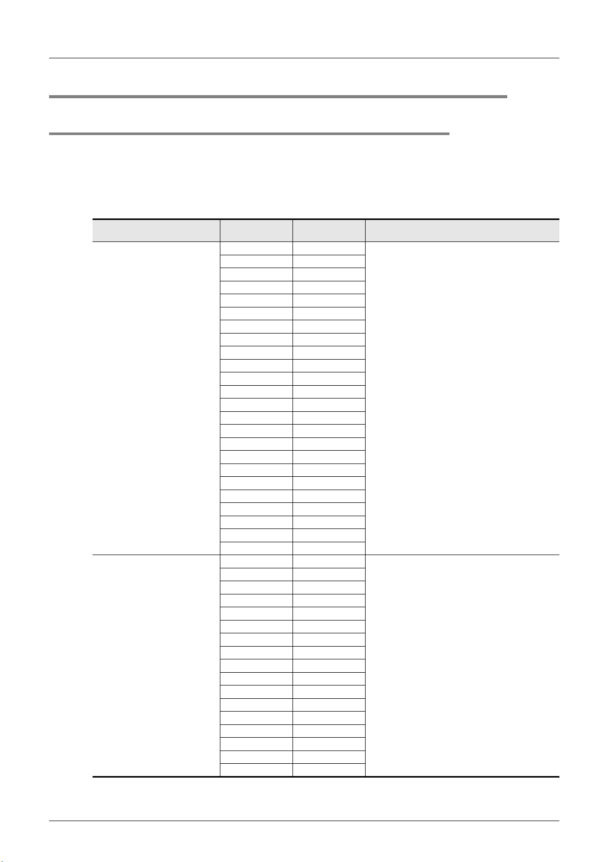
2.4.1 Transmission cycle time
The transmission cycle time is the time required for the 128ASL-M and all the slave modules to update I/O
data.
The transmission cycle time of the 128ASL-M is listed in the table below.
However, "Number of input point settings" and "Number of output point settings" shown in the table below
indicate the number of input points and number of output points assigned to 128ASL-M by the main unit (, so
not set by the rotary switches of the 128ASL-M).
2 Specification
2.4 Communication Specifications
Transmission cycle time
(Rough value)
2.4 ms
3.6 ms
Number of input
point settings
80
88
08
16 0
16 8
16 16
816
016
24 0
24 8
24 16
24 24
16 24
824
024
32 0
32 8
32 16
32 24
32 32
24 32
16 32
832
032
48 0
48 8
48 16
48 24
48 32
48 48
32 48
24 48
16 48
848
048
64 0
64 8
64 16
64 24
64 32
64 48
Number of output
point settings
Condition, remarks
When the larger one between the number of assigned
input points and the number of assigned output points
meets the following expression, the transmission cycle
time becomes the value shown on the left:
Number of input or output points ≤ 32
When the larger one between the number of assigned
input points and the number of assigned output points
meets the following expression, the transmission cycle
time becomes the value shown on the left:
32 < Number of input or output points ≤ 64
18

FX3U-128ASL-M User's Manual
Transmission cycle time
(Rough value)
3.6 ms
4.8 ms
6.0 ms
Number of input
point settings
64 64
48 64
32 64
24 64
16 64
864
064
80 0
80 8
80 16
80 24
80 32
80 48
48 80
32 80
24 80
16 80
880
080
96 0
96 8
96 16
96 24
96 32
32 96
24 96
16 96
896
096
112 0
112 8
112 16
16 112
8112
0112
128 0
0128
Number of output
point settings
2 Specification
2.4 Communication Specifications
Condition, remarks
When the larger one between the number of assigned
input points and the number of assigned output points
meets the following expression, the transmission cycle
time becomes the value shown on the left:
32 < Number of input or output points ≤ 64
When the larger one between the number of assigned
input points and the number of assigned output points
meets the following expression, the transmission cycle
time becomes the value shown on the left:
64 < Number of input or output points ≤ 96
When the larger one between the number of assigned
input points and the number of assigned output points
meets the following expression, the transmission cycle
time becomes the value shown on the left:
96 < Number of input or output points ≤ 128
1
Introduction
2
Specification
3
System
Configuration
4
Installation
5
Wiring, Power-
ON/OFF Timing
6
Introduction of
Functions
7
Buffer Memory
Caution on the transmission cycle time
• The transmission delay time is a value between one and two transmission cycle times due to the double
check (described later).
• To ensure the response, provide an input signal that is longer than two transmission cycle times.
19
8
Program
Examples
9
Troubleshooting
A
Version
Information

FX3U-128ASL-M User's Manual
Sampling timing
Single sample
best case
response time
Single sample
worst case
response time
Input data change Input data update
Input data change
Minimum one transmission
cycle time
Maximum two transmission
cycle times
Input data update
Sampling timing
Sampling timing Sampling timing Sampling timing
2.4.2 Double check
The 128ASL-M performs double check as the error control method.
By double check, the 128ASL-M does not update the data in the input area until it receives the same input
data twice consecutively so that noise errors and other transmission errors can be avoided.
Accordingly, data is updated as described below.
1) Input
In the best case, one transmission cycle time and in the worst case, two transmission cycle times are
required as the input data response time to sample once.
Thus, signals of two transmission cycle times or less may not be sampled twice depending on the timing.
Therefore, to ensure response, provide an input signal that is longer than two transmission cycle times.
2 Specification
2.4 Communication Specifications
2) Output
As double check is performed on the output slave module side, the time required to sample once is the
same as that for input, namely one transmission cycle time in the best case and two transmission cycle
times in the worst case.
Thus, signals of two transmission cycle times or less may not be sampled twice depending on the timing.
Therefore, to ensure response, provide an input signal that is longer than two transmission cycle times.
20

FX3U-128ASL-M User's Manual
Input
Slave module
AnyWireASLINK
system
PLC
[1] Input response time on
the slave module
[2] Processing time on
the slave module
[4] Processing time on
the 128ASL-M
[3] Transmission time =
Transmission cycle time × 2
[5] Processing time on the PLC
= Sequence scan time
2.4.3 Response delay time
The following shows the response delay time of input and output.
1) Input response delay time
The figure below shows the time between a signal input to the slave module and the main unit device
turning ON/OFF.
2 Specification
2.4 Communication Specifications
Configuration
1
Introduction
2
Specification
3
System
4
Installation
[Calculation formula]
Input response delay time =
[1] Input response time on the slave module + [2] Processing time on the slave module +
[3] Transmission cycle time × 2 + [4] Processing time on the 128ASL-M +
[5] Sequence scan time
No. Description Required time
[1] Input response time on the slave module
[2] Processing time on the slave module 1 [ms] maximum (common to all AnyWireASLINK slave modules)
[3] Transmission time (Maximum delay time)
[4] Processing time on the 128ASL-M 0.6 [ms]
[5] Processing time on the PLC Sequence scan time
Refer to the manual for the slave module connected to the system or the
device connected to the slave module.
Transmission cycle time × 2
The transmission cycle time differs depending on the transmission I/O points
setting.
5
Wiring, Power-
ON/OFF Timing
6
Introduction of
Functions
7
Buffer Memory
8
Program
Examples
21
9
Troubleshooting
A
Version
Information
 Loading...