

Mitsubishi Electronics FX3S-30MT, FX3S-MT, FX3G-EEPROM-32L, FX3S-30MR, FX3S-ESS-2AD User Manual
...Page 1

FX3S SERIES PROGRAMMABLE CONTROLLERS
USER'S MANUAL
Hardware Edition
Main Unit
AC Power Type
FX3S-MR/ES
FX3S-MT/ES
FX3S-MT/ESS
FX3S-30MR/ES-2AD
FX3S-30MT/ES-2AD
FX3S-30MT/ESS-2AD
DC Power Type
FX3S-MR/DS
FX3S-MT/DS
FX3S-MT/DSS
Display Module
FX3S-5DM
Memory Cassette
FX3G-EEPROM-32L
Page 2

Page 3
Safety Precautions
(Read these precautions before use.)
Safety Precautions
(Read these precautions before use.)
Before installation, operation, maintenance or inspection of this product, thoroughly read through and
understand this manual and all of the associated manuals. Also, take care to handle the module properly and
safely.
This manual classifies the safety precautions into two categories: and .
Indicates that incorrect handling may cause hazardous conditions, resulting in death or severe
injury.
Indicates that incorrect handling may cause hazardous conditions, resulting in medium or slight
personal injury or physical damage.
Depending on the circumstances, procedures indicated by may also cause severe injury.
It is important to follow all precautions for personal safety.
Store this manual in a safe place so that it can be taken out and read whenever necessary. Always forward it
to the end user.
1. DESIGN PRECAUTIONS
• Make sure to have the following safety circuits outside of the PLC to ensure safe system operation even during
external power supply problems or PLC failure.
Otherwise, malfunctions may cause serious accidents.
1) Most importantly, have the following: an emergency stop circuit, a protection circuit, an interlock circuit for
opposite movements (such as normal vs. reverse rotation), and an interlock circuit (to prevent damage to the
equipment at the upper and lower positioning limits).
2) Note that when the PLC CPU detects an error, such as a watchdog timer error, during self-diagnosis, all outputs
are turned off. Also, when an error that cannot be detected by the PLC CPU occurs in an input/output control
block, output control may be disabled.
External circuits and mechanisms should be designed to ensure safe machinery operation in such a case.
3) If an overload of the 24 V DC service power supply occurs, the voltage automatically drops, inputs in the PLC
are disabled, and all outputs are turned off.
External circuits and mechanisms should be designed to ensure safe machinery operation in such a case.
4) Note that when an error occurs in a relay or transistor output device, the output could be held either on or off.
For output signals that may lead to serious accidents, external circuits and mechanisms should be designed to
ensure safe machinery operation in such a case.
• Do not bundle the control line together with or lay it close to the main circuit or power line. As a guideline, lay the
control line at least 100 mm (3.94") or more away from the main circuit or power line.
Noise may cause malfunctions.
• Install module so that excessive force will not be applied to peripheral device connectors.
Failure to do so may result in wire damage/breakage or PLC failure.
Reference
51
64
74
108
118
Reference
51
64
74
108
118
(1)
Page 4
Safety Precautions
(Read these precautions before use.)
2. INSTALLATION PRECAUTIONS
Reference
• Make sure to cut off all phases of the power supply externally before attempting installation or wiring work.
Failure to do so may cause electric shock or damage to the product.
• Use the product within the generic environment specifications described in Section 4.1 of this manual.
Never use the product in areas with excessive dust, oily smoke, conductive dusts, corrosive gas (salt air, Cl2, H2S,
SO2 or NO2), flammable gas, vibration or impacts, or expose it to high temperature, condensation, or rain and wind.
If the product is used in such conditions, electric shock, fire, malfunctions, deterioration or damage may occur.
• Do not touch the conductive parts of the product directly.
Doing so may cause device failures or malfunctions.
• Install the product securely using a DIN rail or mounting screws.
• Install the product on a flat surface.
If the mounting surface is rough, undue force will be applied to the PC board, thereby causing nonconformities.
• Make sure to affix the expansion board with tapping screws.
Tightening torque should follow the specifications in the manual.
If the screws are tightened outside of the specified torque range, poor connections may cause malfunctions.
• When drilling screw holes or wiring, make sure that cutting and wiring debris do not enter the ventilation slits.
Failure to do so may cause fire, equipment failures or malfunctions.
• Be sure to remove the dust proof sheet from the PLC's ventilation port when installation work is completed.
Failure to do so may cause fire, equipment failures or malfunctions.
• Connect the peripheral device cables securely to their designated connectors.
Loose connections may cause malfunctions.
• Connect the display module, memory cassette and expansion board securely to their designated connectors.
Loose connections may cause malfunctions.
• Turn off the power to the PLC before attaching or detaching the following devices.
Failure to do so may cause device failures or malfunctions.
- Peripheral devices, display module, expansion boards, special adapters and memory cassette
• Connect the memory cassette securely to the appropriate connector.
Loose connections may cause malfunctions.
Installing the cassette in a raised or tilted posture can also cause malfunctions.
51
Reference
51
(2)
Page 5
Safety Precautions
(Read these precautions before use.)
3. WIRING PRECAUTIONS
Reference
• Make sure to cut off all phases of the power supply externally before attempting installation or wiring work.
Failure to do so may cause electric shock or damage to the product.
• Make sure to attach the terminal cover, offered as an accessory, before turning on the power or initiating operation
after installation or wiring work.
Failure to do so may cause electric shock.
• Do not supply power to the [24V] terminal (24 V DC service power supply) on the main unit.
Doing so may cause damage to the product.
• Perform class D grounding (grounding resistance: 100 Ω or less) to the grounding terminal on the main unit with a
wire 2 mm2 or thicker.
Do not use common grounding with heavy electrical systems (refer to Section 8.3).
• Connect the AC power supply wiring to the dedicated terminals described in this manual.
If an AC power supply is connected to a DC input/output terminal or DC power supply terminal, the PLC will burn
out.
• Noise resistance may be lower when the L and N wires of an AC power supply are not wired correctly.
Please wire using the correct polarity.
• Connect the DC power supply wiring to the dedicated terminals described in this manual.
If an AC power supply is connected to a DC input/output terminal or DC power supply terminal, the PLC will burn
out.
• Do not wire vacant terminals externally.
Doing so may damage the product.
• When drilling screw holes or wiring, make sure cutting or wire debris does not enter the ventilation slits.
Failure to do so may cause fire, equipment failures or malfunctions.
• Make sure to observe the following precautions in order to prevent any damage to the machinery or accidents due
to abnormal data written to the PLC under the influence of noise:
1) Do not bundle the power line or shield of the analog input/output cable together with or lay it close to the main
circuit, high-voltage line, or load line.
Otherwise, noise disturbance and/or surge induction are likely to take place. As a guideline, lay the control line
at least 100 mm (3.94") or more away from the main circuit, high-voltage line, or load line.
2) Ground the shield of the analog input/output cable at one point on the signal receiving side.
However, do not use common grounding with heavy electrical systems.
• Make sure to properly wire to the main unit in accordance with the following precautions.
Failure to do so may cause electric shock, equipment failures, a short-circuit, wire breakage, malfunctions, or
damage to the product.
- Make sure to properly wire to the main unit in accordance with the rated voltage, current, and frequency of each
terminal.
- The disposal size of the cable end should follow the dimensions described in the manual.
- Tightening torque should follow the specifications in the manual.
- Tighten the screws using a Phillips-head screwdriver No.2 (shaft diameter 6mm (0.24”) or less). Make sure that
the screwdriver does not touch the partition part of the terminal block.
• Make sure to properly wire to the terminal block (European type) in accordance with the following precautions.
Failure to do so may cause electric shock, equipment failures, a short-circuit, wire breakage, malfunctions, or
damage to the product.
- The disposal size of the cable end should follow the dimensions described in the manual.
- Tightening torque should follow the specifications in the manual.
- Twist the end of strand wire and make sure that there are no loose wires.
- Do not solder-plate the electric wire ends.
- Do not connect more than the specified number of wires or electric wires of unspecified size.
- Affix the electric wires so that neither the terminal block nor the connected parts are directly stressed.
52
65
75
98
109
119
Reference
52
65
75
98
109
112
116
117
119
(3)
Page 6
Safety Precautions
(Read these precautions before use.)
4. STARTUP AND MAINTENANCE PRECAUTIONS
• Do not touch any terminal while the PLC's power is on.
Doing so may cause electric shock or malfunctions.
• Before cleaning or retightening terminals, cut off all phases of the power supply externally.
Failure to do so may cause electric shock.
• Before modifying or disrupting the program in operation or running the PLC, carefully read through this manual and
the associated manuals and ensure the safety of the operation.
An operation error may damage the machinery or cause accidents.
• Do not change the program in the PLC from two or more peripheral equipment devices at the same time. (i.e. from
a programming tool and a GOT)
Doing so may cause destruction or malfunction of the PLC program.
• Turn off the power to the PLC before attaching or detaching the memory cassette. If the memory cassette is
attached or detached while the PLC's power is on, the data in the memory may be destroyed, or the memory
cassette may be damaged.
• Do not disassemble or modify the PLC.
Doing so may cause fire, equipment failures, or malfunctions.
For repair, contact your local Mitsubishi Electric representative.
• Turn off the power to the PLC before connecting or disconnecting any connection cable.
Failure to do so may cause equipment failures or malfunctions.
• Turn off the power to the PLC before attaching or detaching the following devices.
Failure to do so may cause equipment failures or malfunctions.
- Peripheral devices, display module, expansion boards, special adapters and memory cassette
Reference
125
152
Reference
125
152
177
5. DISPOSAL PRECAUTIONS
• Please contact a certified electronic waste disposal company for the environmentally safe recycling and disposal of
your device.
6. TRANSPORTATION AND STORAGE PRECAUTIONS
• The PLC is a precision instrument. During transportation, avoid impacts larger than those specified in the general
specifications (Section 4.1) using dedicated packaging boxes and shock-absorbing palettes. Failure to do so may
cause failures in the PLC.
After transportation, verify operation of the product and check for damage of the mounting part, etc.
Reference
125
Reference
125
(4)
Page 7

FX3S Series Programmable Controllers
User's Manual - Hardware Edition
FX3S Series Programmable Controllers
User's Manual [Hardware Edition]
Manual number JY997D48601
Manual revision C
Date 10/2014
Foreword
This manual contains text, diagrams and explanations which will guide the reader in the correct installation,
safe use and operation of the FX
before attempting to install or use the unit.
And, store this manual in a safe place so that you can take it out and read it whenever necessary. Always
forward it to the end user.
This manual confers no industrial property rights or any rights of any other kind, nor does it confer any patent licenses. Mitsubishi
Electric Corporation cannot be held responsible for any problems involving industrial property rights which may occur as a result of
using the contents noted in this manual.
© 2013 MITSUBISHI ELECTRIC CORPORATION
3S Series Programmable Controllers and should be read and understood
1
Page 8

FX3S Series Programmable Controllers
User's Manual - Hardware Edition
Outline Precautions
• This manual provides information for the use of the FX3S Series Programmable Controllers. The manual
has been written to be used by trained and competent personnel. The definition of such a person or
persons is as follows;
a) Any engineer who is responsible for the planning, design and construction of automatic equipment
using the product associated with this manual should be of a competent nature, trained and qualified
to the local and national standards required to fulfill that role. These engineers should be fully aware of
all aspects of safety with regards to automated equipment.
b) Any commissioning or service engineer must be of a competent nature, trained and qualified to the
local and national standards required to fulfill that job. These engineers should also be trained in the
use and maintenance of the completed product. This includes being completely familiar with all
associated documentation for the said product. All maintenance should be carried out in accordance
with established safety practices.
c) All operators of the completed equipment should be trained to use that product in a safe and
coordinated manner in compliance to established safety practices. The operators should also be
familiar with documentation which is connected with the actual operation of the completed equipment.
Note: The term 'completed equipment' refers to a third party constructed device which contains or uses
the product associated with this manual
• This product has been manufactured as a general-purpose part for general industries, and has not been
designed or manufactured to be incorporated in a device or system used in purposes related to human life.
• Before using the product for special purposes such as nuclear power, electric power, aerospace, medicine
or passenger movement vehicles, consult with Mitsubishi Electric.
• This product has been manufactured under strict quality control. However when installing the product
where major accidents or losses could occur if the product fails, install appropriate backup or failsafe
functions in the system.
• When combining this product with other products, please confirm the standard and the code, or regulations
with which the user should follow. Moreover, please confirm the compatibility of this product to the system,
machine, and apparatus with which a user is using.
• If in doubt at any stage during the installation of the product, always consult a professional electrical
engineer who is qualified and trained to the local and national standards. If in doubt about the operation or
use, please consult your local Mitsubishi Electric representative.
• Since the examples indicated by this manual, technical bulletin, catalog, etc. are used as a reference,
please use it after confirming the function and safety of the equipment and system. Mitsubishi Electric will
accept no responsibility for actual use of the product based on these illustrative examples.
• This manual content, specification etc. may be changed without a notice for improvement.
• The information in this manual has been carefully checked and is believed to be accurate; however, if you
have noticed a doubtful point, a doubtful error, etc., please contact your local Mitsubishi Electric
representative.
Registration
•Microsoft and Windows are either registered trademarks or trademarks of Microsoft Corporation in the
United States and/or other countries.
• Ethernet is a trademark of Xerox Corporation.
•MODBUS
• Phillips is a registered trademark of Phillips Screw Company.
• The company name and the product name to be described in this manual are the registered trademarks or
trademarks of each company.
2
is a registered trademark of Schneider Electric SA.
Page 9

FX3S Series Programmable Controllers
User's Manual - Hardware Edition
Table of Contents
SAFETY PRECAUTIONS ..................................................................................................(1)
Standards................................................................................................................................. 10
Certification of UL, cUL standards ..................................................................................................... 10
Compliance with EC directive (CE Marking) ...................................................................................... 10
Requirement for Compliance with EMC directive .................................................................................. 10
Requirement for Compliance with LVD directive................................................................................... 11
Caution for compliance with EC Directive .............................................................................................12
1. Introduction 13
1.1 Introduction of Manuals................................................................................................................. 13
1.1.1 Classification of major components in this manual........................................................................13
1.1.2 Manual organization and position of this manual ..........................................................................14
1.1.3 List of manuals ..............................................................................................................................15
1.2 Generic Names and Abbreviations Used in Manuals.................................................................... 18
2. Features and Part Names 19
Table of Contents
2.1 Major Features .............................................................................................................................. 19
2.2 Names and Functions of Parts...................................................................................................... 21
2.2.1 Front Panel....................................................................................................................................21
2.2.2 Sides.............................................................................................................................................. 23
3. Introduction of Products 24
3.1 List of Products and Interpretation of Model Names..................................................................... 24
3.1.1 Main units ...................................................................................................................................... 25
3.1.2 Expansion boards.......................................................................................................................... 26
3.1.3 Connector conversion adapter ...................................................................................................... 26
3.1.4 Special adapters............................................................................................................................ 26
3.1.5 Display module.............................................................................................................................. 26
3.1.6 Memory cassette ........................................................................................................................... 26
3.2 Connector Types and Cables for Program Communication.......................................................... 27
3.2.1 Programming tool .......................................................................................................................... 28
3.2.2 Communication cables .................................................................................................................. 28
3.2.3 Converters and interface ............................................................................................................... 28
4. Specifications, External Dimensions and Terminal Layout (Main Units) 29
4.1 Generic Specifications ..................................................................................................................29
4.1.1 Dielectric withstand voltage test and insulation resistance test..................................................... 30
4.2 Power Supply Specifications......................................................................................................... 30
4.2.1 AC power type............................................................................................................................... 30
4.2.2 DC power type............................................................................................................................... 30
4.3 Input Specifications ....................................................................................................................... 31
4.3.1 24 V DC Input (sink/source) .......................................................................................................... 31
4.4 Output Specifications .................................................................................................................... 32
4.4.1 Relay output specifications............................................................................................................32
4.4.2 Transistor output specifications.....................................................................................................33
4.5 Performance Specifications .......................................................................................................... 34
4.6 External Dimensions (Weight/Accessories/Installation) ................................................................ 36
4.6.1 Main units ...................................................................................................................................... 36
3
Page 10

FX3S Series Programmable Controllers
User's Manual - Hardware Edition
4.7 Terminal Layout ............................................................................................................................ 37
4.7.1 Interpretation of terminal block layout............................................................................................ 37
4.7.2 FX3S-10M...................................................................................................................................38
4.7.3 FX3S-14M...................................................................................................................................38
4.7.4 FX
4.7.5 FX3S-30M...................................................................................................................................39
3S-20M...................................................................................................................................39
5. Version Information and Peripheral Equipment Connectability 40
5.1 Version Information ....................................................................................................................... 40
5.1.1 Manufacturer's serial number check method.................................................................................40
5.1.2 Version check method................................................................................................................... 41
5.1.3 Version upgrade history................................................................................................................. 41
5.2 Programming Tool Applicability..................................................................................................... 41
5.2.1 Applicable versions of programming tool....................................................................................... 41
5.2.2 In the case of programming tool (version) not applicable..............................................................41
5.2.3 Program transfer speed and programming tools ........................................................................... 42
5.2.4 Cautions on connecting peripheral equipment by way of expansion board or special adapter ..... 42
5.2.5 Cautions on write during RUN.......................................................................................................43
5.3 Use of (Built-in USB) Programming Port....................................................................................... 45
5.3.1 Installation of USB driver............................................................................................................... 45
5.3.2 Setting in GX Works2 .................................................................................................................... 45
5.4 Cautions on using FA transparent function in GOT1000 Series ................................................... 46
5.5 Cautions on using transparent port (2-port) function of GOT-F900 Series ................................... 47
5.6 Other Peripheral Equipment Applicability...................................................................................... 48
5.6.1 Other peripheral equipment applicability ....................................................................................... 48
Table of Contents
6. Examination of System Configuration 49
6.1 Configuration of a Whole System.................................................................................................. 49
6.1.1 Expansion board/connector conversion adapter/memory cassette system configuration............. 49
6.1.2 Special adapter system configuration............................................................................................50
7. Installation In Enclosure 51
7.1 Installation location........................................................................................................................ 53
7.1.1 Installation location in enclosure.................................................................................................... 53
7.1.2 Space in enclosure........................................................................................................................ 53
7.2 Examination for Installing Method in Enclosure ............................................................................ 54
7.3 Procedures for Installing on and Detaching from DIN Rail............................................................ 54
7.3.1 Preparation for installation.............................................................................................................54
7.3.2 Installation of main unit.................................................................................................................. 55
7.3.3 Removal of main unit.....................................................................................................................56
7.4 Procedures for Installing Directly (with M4 screws) ......................................................................57
7.4.1 Hole pitches for direct mounting....................................................................................................57
7.4.2 Example of mounting hole pitches.................................................................................................58
7.4.3 Installation of main unit.................................................................................................................. 58
7.5 Connecting Methods for Main Unit and Extension Devices .......................................................... 58
7.5.1 Connection of extension devices................................................................................................... 58
7.5.2 Connecting method A - connection of expansion board................................................................ 59
7.5.3 Connecting method B - connection of connector conversion adapter ........................................... 60
7.5.4 Connecting method C - connection of special adapter.................................................................. 61
7.6 Application of labels ...................................................................................................................... 62
7.6.1 Application of Station No. label (FX3G-485-BD)............................................................................62
7.6.2 Application of Station No. label (FX
7.6.3 Application of trimmer layout Label (FX
3G-485-BD-RJ) ......................................................................62
3G-8AV-BD)..................................................................... 63
4
Page 11

FX3S Series Programmable Controllers
User's Manual - Hardware Edition
8. Preparation for Wiring and Power Supply Wiring Procedures 64
8.1 Preparation for Wiring ................................................................................................................... 66
8.1.1 Wiring procedures .........................................................................................................................66
8.2 Cable Connecting Procedures ...................................................................................................... 67
8.2.1 Terminal block [Main unit].............................................................................................................. 67
8.2.2 Terminal block (for European) [expansion board and special adapters] .......................................68
8.2.3 Grounding terminal of the FX3G-485-BD-RJ ................................................................................. 69
8.2.4 Grounding terminal of the FX
3U-ENET-ADP.................................................................................70
8.3 Grounding .....................................................................................................................................71
8.4 Examples of External Wiring [AC power type] ..............................................................................72
8.5 Examples of External Wiring [DC power type] .............................................................................. 73
9. Input Wiring Procedures 74
9.1 Before Starting Input Wiring.......................................................................................................... 76
9.1.1 Sink and source input.................................................................................................................... 76
9.2 24 V DC input (Sink and source input type) .................................................................................. 77
9.2.1 Handling of 24 V DC input ............................................................................................................. 77
9.2.2 Instructions for connecting input devices....................................................................................... 78
9.2.3 Examples of external wiring [AC power type] ................................................................................ 80
9.2.4 Examples of external wiring [DC power type]................................................................................ 81
9.3 Input Interruption (I00 to I50) .................................................................................................. 82
9.3.1 Allocation of pointers to input numbers (input signal ON/OFF duration) ....................................... 82
9.3.2 Cautions for input interruption ....................................................................................................... 82
9.3.3 Examples of external wiring........................................................................................................... 83
9.4 Pulse Catch (M8170 to M8175) .................................................................................................... 84
9.4.1 Allocation of special memories to input numbers (ON duration of input signals) .......................... 84
9.4.2 Cautions for pulse catch................................................................................................................ 84
9.4.3 Examples of external wiring........................................................................................................... 85
Table of Contents
10. Use of High-speed Counters 86
10.1 Outline......................................................................................................................................... 86
10.2 Types of Counting and Operations .............................................................................................86
10.2.1 Types and input signal forms....................................................................................................... 86
10.2.2 High-speed counter device notations .......................................................................................... 86
10.2.3 Cautions in connecting mating device......................................................................................... 86
10.3 List of Device Numbers and Functions .......................................................................................87
10.4 Allocation of Device Numbers to Input Numbers ........................................................................88
10.4.1 Allocation table ............................................................................................................................ 88
10.4.2 Restriction of redundant use of input numbers............................................................................88
10.5 Handling of High-speed Counters............................................................................................... 89
10.5.1 1-phase 1-count input.................................................................................................................. 89
10.5.2 1-phase 2-count input.................................................................................................................. 90
10.5.3 2-phase 2-count input.................................................................................................................. 91
10.6 Timing of Updating of Current Value and Comparison of Current Value .................................... 92
10.6.1 Timing of updating of current value .............................................................................................92
10.6.2 Comparison of current value ....................................................................................................... 92
10.7 Response Frequency and Overall Frequency............................................................................. 93
10.8 Examples of External Wiring (Rotary Encoder)........................................................................... 94
10.8.1 1-phase 1-input [C235 to C245] .................................................................................................. 94
10.8.2 2-phase 2-input [C251 to C255] .................................................................................................. 95
10.9 Related Devices and Function Switching Procedures ................................................................96
10.9.1 Related devices........................................................................................................................... 96
10.9.2 [Function switching] switching of allocation and functions of input terminals .............................. 97
10.10 Cautions on Use........................................................................................................................ 97
5
Page 12

FX3S Series Programmable Controllers
User's Manual - Hardware Edition
11. Use of Built-in Analog 98
11.1 Outline......................................................................................................................................... 99
11.2 Built-in variable analog potentiometer function ...........................................................................99
11.2.1 Outline of functions...................................................................................................................... 99
11.2.2 Applicable PLC............................................................................................................................ 99
11.2.3 Special data register.................................................................................................................... 99
11.2.4 Use example of variable analog potentiometer ......................................................................... 100
11.3 Built-in analog input function..................................................................................................... 101
11.3.1 Outline of functions.................................................................................................................... 101
11.3.2 Applicable PLC.......................................................................................................................... 101
11.3.3 Analog input performance specifications................................................................................... 101
11.3.4 Analog input terminal block ....................................................................................................... 102
11.3.5 Terminal layout.......................................................................................................................... 103
11.3.6 Analog input line........................................................................................................................ 103
11.3.7 Special data register..................................................................................................................103
11.3.8 Program example ...................................................................................................................... 105
11.3.9 Changing of input characteristics .............................................................................................. 105
11.3.10 Troubleshooting when using built-in analog input ................................................................... 106
Table of Contents
12. Output Wiring Procedures 108
12.1 External Wiring for Relay Output Type...................................................................................... 110
12.1.1 Product life of relay contacts ..................................................................................................... 110
12.1.2 Handling of relay output............................................................................................................. 110
12.1.3 External wiring precautions .......................................................................................................111
12.1.4 Example of external wiring ........................................................................................................ 112
12.2 External Wiring of Transistor Output (Sink/Source) Type ......................................................... 113
12.2.1 Transistor Output Sink and Source ...........................................................................................113
12.2.2 Handling of transistor output...................................................................................................... 113
12.2.3 External wiring precautions ....................................................................................................... 115
12.2.4 Example of external wiring ........................................................................................................ 116
13. Examples of Wiring for Various Uses 118
13.1 Notes about Examples of Wiring............................................................................................... 119
13.2 Digital Switch [DSW Instruction (FNC 72)/BIN Instruction (FNC 19)] ....................................... 120
13.2.1 When DSW instruction (FNC 72) is used .................................................................................. 120
13.2.2 When BIN instruction (FNC 19) is used..................................................................................... 121
13.3 Input Matrix [MTR Instruction (FNC 52)] ................................................................................... 122
13.4 Seven Segment with Latch [SEGL Instruction (FNC 74)/BCD Instruction (FNC 18)] ............... 123
13.4.1 When SEGL instruction (FNC 74) is used .................................................................................123
13.4.2 When BCD instruction (FNC 18) is used................................................................................... 124
14. Test Operation, Adjustment, Maintenance and Troubleshooting 125
14.1 Preparation for Test Operation.................................................................................................. 126
14.1.1 Preliminary inspection [power OFF] .......................................................................................... 126
14.1.2 Connection to peripheral device connecting connector (RS-422) .............................................126
14.1.3 Connection to peripheral device connecting connector (USB) .................................................. 127
14.1.4 Writing of program and program check [power ON and PLC stopped] ..................................... 127
14.2 Running and Stopping Procedures [Power ON]........................................................................ 128
14.2.1 Methods of running and stopping .............................................................................................. 128
14.2.2 Use of several running/stopping methods .................................................................................129
14.3 Operation and Test [Power ON and PLC Running] ..................................................................130
14.3.1 Self-diagnostic function ............................................................................................................. 130
14.3.2 Test functions ............................................................................................................................ 130
6
Page 13

FX3S Series Programmable Controllers
User's Manual - Hardware Edition
14.3.3 Program modification function ................................................................................................... 130
14.4 Maintenance and Periodic Inspection ....................................................................................... 131
14.4.1 Periodic inspection .................................................................................................................... 131
14.4.2 Maintenance - product life of relay contacts............................................................................. 131
14.5 Troubleshooting with LEDs ....................................................................................................... 132
14.5.1 POW LED [on/flashing/off]......................................................................................................... 132
14.5.2 ERR LED [on/flashing/off].......................................................................................................... 132
14.6 Judgment by Error Codes and Representation of Error Codes ................................................133
14.6.1 Operation and check by GX Works2 ......................................................................................... 133
14.6.2 Representation of errors............................................................................................................ 134
14.6.3 Error Code List and Action ........................................................................................................ 135
14.7 Troubleshooting ........................................................................................................................ 140
14.7.1 Output does not operate............................................................................................................ 140
14.7.2 24 V DC input does not operate ................................................................................................140
14.7.3 Cautions in registering keyword ................................................................................................ 141
15. Other Extension Devices and Optional Units
(External Dimensions and Terminal Arrangement) 142
15.1 Special Adapters....................................................................................................................... 142
15.1.1 FX3U-4AD-ADP ......................................................................................................................... 142
15.1.2 FX3U-4DA-ADP ......................................................................................................................... 142
15.1.3 FX3U-3A-ADP............................................................................................................................ 143
15.1.4 FX
15.1.5 FX3U-4AD-PNK-ADP ................................................................................................................ 143
15.1.6 FX3U-4AD-TC-ADP ...................................................................................................................144
15.1.7 FX
15.1.8 FX3U-485ADP(-MB) .................................................................................................................. 145
15.1.9 FX3U-ENET-ADP ...................................................................................................................... 145
15.2 Expansion Board....................................................................................................................... 146
15.2.1 FX3G-4EX-BD ........................................................................................................................... 146
15.2.2 FX3G-2EYT-BD .........................................................................................................................146
15.2.3 FX
15.2.4 FX3G-422-BD ............................................................................................................................147
15.2.5 FX3G-485-BD ............................................................................................................................148
15.2.6 FX
15.2.7 FX
15.2.8 FX
15.2.9 FX
15.3 Connector Conversion Adapter................................................................................................. 151
15.3.1 FX3S-CNV-ADP......................................................................................................................... 151
15.4 Interface Module ....................................................................................................................... 151
15.4.1 FX-232AWC-H........................................................................................................................... 151
3U-4AD-PT(W)-ADP ............................................................................................................. 143
3U-232ADP(-MB) .................................................................................................................. 144
3G-232-BD ............................................................................................................................147
3G-485-BD-RJ....................................................................................................................... 148
3G-2AD-BD ........................................................................................................................... 149
3G-1DA-BD ........................................................................................................................... 149
3G-8AV-BD ........................................................................................................................... 150
Table of Contents
16. Display Module (FX3S-5DM) 152
16.1 Specifications ............................................................................................................................ 152
16.1.1 Applicable PLC.......................................................................................................................... 152
16.1.2 Display Specifications................................................................................................................ 152
16.1.3 External Dimensions and Part Names.......................................................................................153
16.2 Installation and Removal........................................................................................................... 153
16.2.1 Installation and Removal
(when the expansion board/connector conversion adapter is not used together)...................... 153
16.2.2 Installation and Removal
(when the expansion board/connector conversion adapter is used together)............................ 154
16.3 Summary of Functions .............................................................................................................. 155
16.4 Flowing of the Screen Display................................................................................................... 156
16.5 Monitor/Test ..............................................................................................................................157
16.5.1 Relevant devices ....................................................................................................................... 157
16.5.2 Selecting a device .....................................................................................................................157
7
Page 14

FX3S Series Programmable Controllers
User's Manual - Hardware Edition
16.5.3 When "Input (X)", "Output (Y)", "Auxiliary relay (M)" or "State (S)" is selected ......................... 158
16.5.4 When "Timer (T)" is selected.....................................................................................................160
16.5.5 When "Counter (C)" is selected................................................................................................. 162
16.5.6 When "Data register (D)" is selected .........................................................................................164
16.6 Time Display and Setting .......................................................................................................... 166
16.7 Error Display ............................................................................................................................. 166
16.8 5DM Control Functions (Restrictions From PLC)...................................................................... 167
16.8.1 System information list .............................................................................................................. 167
16.8.2 System information setting program example ........................................................................... 168
16.9 Specified Device Monitor Function............................................................................................ 168
16.9.1 System information - specified device monitor function ............................................................ 168
16.9.2 Program example1 .................................................................................................................... 169
16.9.3 Program example2 (when monitoring consecutive timers using operation button) ................... 170
16.9.4 Program example3 (when monitoring non-consecutive timers using operation buttons) .......... 171
16.9.5 Specified device editing function ............................................................................................... 172
16.10 Back light off function.............................................................................................................. 174
16.10.1 System Information - Back light off function ............................................................................ 174
16.11 Display Screen Protect Function............................................................................................. 175
16.11.1 System information - display screen protect function ..............................................................175
16.11.2 Program example (screen protect function setting)................................................................. 175
16.12 Error display enable/disable.................................................................................................... 175
16.13 Operation Button ON/OFF Information ...................................................................................176
16.13.1 Various applications ................................................................................................................ 176
16.13.2 System information - operation button ON/OFF information ................................................... 176
16.14 Specifying a Decimal/Hexadecimal Current Value Display Format ........................................ 176
Table of Contents
17. Memory Cassette 177
17.1 Outline....................................................................................................................................... 177
17.2 Specifications ............................................................................................................................ 177
17.2.1 Electrical specifications ............................................................................................................. 177
17.2.2 Part names and external dimensions ........................................................................................177
17.3 Installation ................................................................................................................................. 178
17.3.1 Installation (when the expansion board/connector conversion adapter is not used together)... 178
17.3.2 Installation (when the expansion board/connector conversion adapter is used together)......... 179
17.4 Removal .................................................................................................................................... 181
17.4.1 Removal (when the expansion board/connector conversion adapter are not used together) ... 181
17.4.2 Removal (when the expansion board/connector conversion adapter are used together) ......... 182
17.5 Saved Data Content.................................................................................................................. 183
17.6 PROTECT Switch ..................................................................................................................... 184
17.6.1 PROTECT switch setting...........................................................................................................184
17.6.2 PROTECT switch operation ...................................................................................................... 184
17.6.3 Precautions when setting and using the switch......................................................................... 184
17.7 Memory Cassette <-> PLC (EEPROM Memory) Transfers by Loader Function....................... 185
17.7.1 Writing (WR: FX3G-EEPROM-32L -> PLC)............................................................................... 185
17.7.2 Reading (RD: FX
3G-EEPROM-32L <- PLC) .............................................................................186
17.8 Memory cassette precautions for use ....................................................................................... 186
Appendix A: Special Device List 187
Appendix A-1 Special Auxiliary Relay (M8000 to M8511) ........................................................ 187
Appendix A-2 Special Data Register (D8000 to D8511) ........................................................... 193
Appendix A-3 Analog expansion boards [M8260 to M8269 and D8260 to D8269] .................. 198
Appendix A-3-1 Special auxiliary relays (M8260 to M8269)................................................................. 198
Appendix A-3-2 Special data registers (D8260 to D8269).................................................................... 198
Appendix A-4 Analog special adapters [M8280 to M8289 and D8280 to D8289]..................... 199
Appendix A-4-1 Special auxiliary relays (M8280 to M8289)................................................................. 199
Appendix A-4-2 Special data registers (D8280 to D8289).................................................................... 200
8
Page 15

FX3S Series Programmable Controllers
User's Manual - Hardware Edition
Appendix B: Instruction List 201
Appendix B-1 Basic Instructions ............................................................................................... 201
Appendix B-2 Step Ladder Instructions .................................................................................... 201
Appendix B-3 Applied Instructions ... in Ascending Order of FNC Number .............................. 202
Appendix C: Discontinued models 205
Warranty................................................................................................................................. 207
Revised History ..................................................................................................................... 208
Table of Contents
9
Page 16

FX3S Series Programmable Controllers
User's Manual - Hardware Edition
Standards
Certification of UL, cUL standards
FX3S series main units, FX3S series interface adapter and FX3U series special adapters supporting UL, cUL
standards are as follows:
UL, cUL file number: E95239
Models: MELSEC FX
FX3S-MR/ES FX3S-MT/ES FX3S-MT/ESS
FX3S-MR/DS FX3S-MT/DS FX3S-MT/DSS
Where indicates:10, 14, 20, 30
FX3S-30MR/ES-2AD FX3S-30MT/ES-2AD FX3S-30MT/ESS-2AD
FX3S-CNV-ADP
FX3U-232ADP(-MB) FX3U-485ADP(-MB) FX3U-ENET-ADP
FX3U-4AD-ADP FX3U-4DA-ADP FX3U-3A-ADP FX3U-4AD-PT-ADP
FX3U-4AD-PTW-ADP FX3U-4AD-PNK-ADP FX3U-4AD-TC-ADP
3S/FX3U series manufactured
Standards
Compliance with EC directive (CE Marking)
This note does not guarantee that an entire mechanical module produced in accordance with the contents of
this note will comply with the following standards.
Compliance to EMC directive and LVD directive of the entire mechanical module should be checked by the
user / manufacturer. For more details please contact to the local Mitsubishi Electric sales site.
Requirement for Compliance with EMC directive
The following products have shown compliance through direct testing (of the identified standards below) and
design analysis (through the creation of a technical construction file) to the European Directive for
Electromagnetic Compatibility (2004/108/EC) when used as directed by the appropriate documentation.
Attention
• This product is designed for use in industrial applications.
Note
• Manufactured by:
Mitsubishi Electric Corporation
2-7-3 Marunouchi, Chiyoda-ku, Tokyo, 100-8310 Japan
• Manufactured at:
Mitsubishi Electric Corporation Himeji Works
840 Chiyoda-machi, Himeji, Hyogo, 670-8677 Japan
• Authorized Representative in the European Community:
Mitsubishi Electric Europe B.V.
Gothaer Str. 8, 40880 Ratingen, Germany
10
Page 17

FX3S Series Programmable Controllers
User's Manual - Hardware Edition
Type: Programmable Controller (Open Type Equipment)
Models: MELSEC FX
from June 1st, 2005 FX3U-232ADP FX3U-485ADP
from April 1st, 2007 FX3U-232ADP-MB FX3U-485ADP-MB
from December 1st, 2007 FX3U-4AD-PTW-ADP FX3U-4AD-PNK-ADP
from November 1st, 2008 FX3G-232-BD FX3G-422-BD FX3G-485-BD
from June 1st, 2009 FX3U-3A-ADP
from February 1st, 2012 FX3U-ENET-ADP
from March 1st, 2013 FX3S-MR/ES FX3S-MT/ES FX3S-MT/ESS
from September 1st, 2013 FX3S-MR/DS FX3S-MT/DS FX3S-MT/DSS
from September 1st, 2014 FX3S-5DM
3S series, FX3G series, FX3U series manufactured
FX3U-4AD-ADP FX3U-4DA-ADP FX3U-4AD-PT-ADP FX3U-4AD-TC-ADP
FX3G-EEPROM-32L
FX3G-2AD-BD FX3G-1DA-BD FX3G-8AV-BD
Where indicates:10, 14, 20, 30
FX3S-CNV-ADP
Where indicates:10, 14, 20, 30
FX3S-30MR/ES-2AD FX3S-30MT/ES-2AD FX3S-30MT/ESS-2AD
FX3G-4EX-BD FX3G-2EYT-BD FX3G-485-BD-RJ
Standards
Standard Remark
EN61131-2: 2007 Programmable controllers
- Equipment requirements and tests
Requirement for Compliance with LVD directive
The following products have shown compliance through direct testing (of the identified standards below) and
design analysis (through the creation of a technical construction file) to the European Directive for Low
Voltage (2006/95/EC) when used as directed by the appropriate documentation.
Type: Programmable Controller (Open Type Equipment)
Models: MELSEC FX
from March 1st, 2013 FX3S-MR/ES FX3S-MT/ES FX3S-MT/ESS
from September 1st, 2013 FX3S-MR/DS
3S series manufactured
Where indicates:10, 14, 20, 30
Where indicates:10, 14, 20, 30
FX3S-30MR/ES-2AD FX3S-30MT/ES-2AD FX3S-30MT/ESS-2AD
Compliance with all relevant aspects of the standard.
EMI
• Radiated Emission
• Conducted Emission
EMS
• Radiated electromagnetic field
• Fast transient burst
• Electrostatic discharge
• High-energy surge
• Voltage drops and interruptions
• Conducted RF
• Power frequency magnetic field
Standard Remark
EN61131-2: 2007 Programmable controllers
- Equipment requirements and tests
The equipment has been assessed as a component for fitting in a suitable
enclosure which meets the requirements of EN61131-2: 2007
11
Page 18

FX3S Series Programmable Controllers
User's Manual - Hardware Edition
Caution for compliance with EC Directive
1. Installation in Enclosure
Programmable logic controllers are open-type devices that must be installed and used within conductive
control boxes. Please use the FX
shielded control boxes. Please secure the control box lid to the control box (for conduction). Installation within
a control box greatly affects the safety of the system and aids in shielding noise from the programmable logic
controller.
2. Caution for Analog Products in use
The analog products have been found to be compliant to the European standards in the aforesaid manual
and directive. However, for the very best performance from what are in fact delicate measuring and controlled
output devices, Mitsubishi Electric would like to make the following points;
As analog devices are sensitive by nature, their use should be considered carefully. For users of proprietary
cables (integral with sensors or actuators), these users should follow those manufacturers' installation
requirements.
Mitsubishi Electric recommends that shielded cables be used. If NO other EMC protection is provided, users
may experience temporary loss or accuracy between +10% / -10% in very heavy industrial areas.
However, Mitsubishi Electric suggests that if adequate EMC precautions are followed for the users complete
control system.
- Sensitive analog cables should not be laid in the same trunking or cable conduit as high voltage cabling.
Where possible, users should run analog cables separately.
- Good cable shielding should be used. When terminating the shield at Earth - ensure that no earth loops
are accidentally created.
- When reading analog values, EMC accuracy can be improved by averaging the readings. This can be
achieved either through functions on the analog product or through a user's program in the FX
PLC main unit.
3S Series programmable logic controllers while installed in conductive
Standards
3S Series
12
Page 19

FX3S Series Programmable Controllers
User's Manual - Hardware Edition
1. Introduction
1 Introduction
1.1 Introduction of Manuals
1
Introduction
This manual explains the procedures for selecting the system components, main unit specifications and
procedures for installing the main unit, and procedures for operating the display module etc. FX
make various kinds of control in combination with the main unit functions and many extension devices
(expansion board and special adapters).
The detailed explanation of the sequence instructions, communication control, analog control and positioning
control are given in separate manuals.
For information on manual organization, refer to Subsection 1.1.2.
1.1 Introduction of Manuals
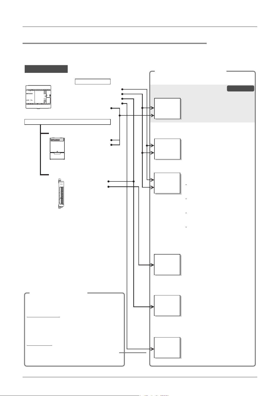
1.1.1 Classification of major components in this manual
1) Main unit (Chapter 1 to Chapter 14)
Division Outline Reference
Introduction of manuals
Features and part names This chapter contains explanations of the product features and the names of the parts. Chapter 2
Introduction of product
Specifications
Version information
System configuration Procedure for determining whether or not a system configuration is possible. Chapter 6
Installation
Power supply wiring
Input wiring This chapter contains explanations of the input wiring and wiring precautions. Chapter 9
High-speed counter
Built-in analog
Output wiring This chapter contains explanations for the output wiring and wiring precautions. Chapter 12
Examples of wiring for each use
Test operation, adjustment,
maintenance and error check
2) Extension devices (Chapter 15)
Division Outline Reference
Extension products for special
functions, such as communication
control and analog.
3) Optional products (Chapter 16 to Chapter17)
Division Outline Reference
Display module
Memory cassette
This chapter contains explanations of the procedures for obtaining the manuals and
the abbreviations.
This chapter contains explanations of the structures for model names, extension
products.
This chapter contains explanations of the specifications for power supply and input/
output, performance specifications, external dimensions and terminal block layout.
This chapter contains explanation for upgrading of FX3S PLCs and information for the
application of programming tools.
This chapter contains explanations for the panel layout and the procedures for
installing with DIN rail or screws.
This chapter contains explanations of the procedures for preparing for wiring, power
supply wiring and wiring precautions.
This chapter contains explanations of the procedures for using the high-speed counter
examples of programming.
This chapter contains explanations of the procedures for using the built-in variable
analog potentiometer and the built-in analog input and programming examples.
This chapter contains explanations of the procedures for wiring input/output devices
for main uses.
This chapter contains explanations of the procedures for test operation and
adjustment, maintenance and error check items and measures to be taken upon
occurrence of error.
This chapter contains explanations for the external dimensions and terminal layout
(For details, refer to the manual for each extension device).
This chapter contains explanation of the specifications, external dimensions, mounting
procedures and operating procedures for display modules (FX3S-5DM).
This chapter contains explanations of the specifications for the memory cassette and
the installation procedures.
3S PLCs can
Chapter 1
Chapter 3
Chapter 4
Chapter 5
Chapter 7
Chapter 8
Chapter 10
Chapter 11
Chapter 13
Chapter 14
Chapter 15
Chapter 16
Chapter 17
2
Features and
Part Names
3
Product
Introduction
4
Specifications
5
Version and
Peripheral
Devices
6
System
Configuration
7
Installation
8
Preparation and
Power Supply
Wiring
9
Input Wiring
4) Others (Appendix A to Appendix C)
Division Outline Reference
List of special devices
List of instructions
List of discontinued models
This chapter contains an explanation list of the special auxiliary relays (M8000 to
M8511) and special data registers (D8000 to D8511).
(For details, refer to the programming manual.)
This chapter contains an explanation list of the basic instructions and applied
instructions. (For details, refer to the programming manual.)
The discontinued MELSEC-F Series PLC models and programming tools described in
this manual.
Appendix A
Appendix B
Appendix C
13
10
High-Speed
Counters
Page 20
FX3S Series Programmable Controllers
The part names, installation procedures and
specifications are shown.
As for the functions and program examples, refer to
the separate User's Manual - Edition).
User's Manual - Hardware Edition
JY997D48601 (Model: FX3S-HW-E)
FX
3S
separate
manual
Manual for each use (separate volume)
Programming Manual - Basic & Applied Instruction
JY997D16601 (Model: FX-P3-E)
Main unit
• Sequence instructions
• High-speed counter
• PID instruction
• Built-in analog
• Positioning instructions
Built-in functions
Options
• Memory cassette
Expansion boards, Special adapters
• Analog
• Communication
Installation manual
User's manual
Manuals supplied with product
Additional options
Structured Programming Manual
FX
separate
manual
For details on structured programming,
refer to the following manual.
MELSEC-Q/L/F Structured
Programming Manual (Fundamentals)
SH-080782 (Model: Q/FX-KP-KI-E)
FXCPU Structured Programming
Manual [Device & Common]
JY997D26001 (Model: FX-KP-DK-E)
FXCPU Structured Programming
Manual [Basic & Applied instruction]
JY997D34701 (Model: FX-KP-SM-E)
FXCPU Structured Programming
Manual [Application Functions]
JY997D34801 (Model: FX-KP-OK-E)
User's Manual - Positioning Control Edition
JY997D16801 (Model: FX3U-U-POS-E)
FX3S/FX3G/FX
3GC
/
FX
3U
/FX
3UC
separate manual
FX
3S
/FX3G/FX
3GC
/
FX
3U
/FX
3UC
separate manual
The manuals for FX3S Series will be
available in or after May, 2013.
The manuals for FX
3S Series will be
available in or after May, 2013.
Details of hardware, including
input/output specifications, wiring,
installation and maintenance of PLC
main unit
Details of sequence program,
including basic and applied
instructions and various devices
User's Manual - Analog Control Edition
JY997D16701 (Model: FX3U-U-ANALOG-E)
FX3S/FX3G/FX
3GC
/
FX
3U
/FX
3UC
separate manual
The manuals for FX3S Series will be
available in or after May, 2013.
Details of analog expansion boards
and analog special adapters
User's Manual - Data Communication Edition
JY997D16901 (Model: FX-U-COMMU-E)
FX
separate
manual
The manuals for FX3S Series will be
available in or after May, 2013.
Details of N:N Network, parallel link,
computer link, non-protocol
communication and programming
communication
Details of wiring, instructions and
operations of positioning functions in
PLC main unit
FX3S Series
This manual
Refer to the manual for each purpose of use.
Each product comes with the installation manual or
the User's Manual.
To use some products, separate manuals may be necessary.
The procedures for wiring and installing, specifications
and functions are explained.
• Display module
User's Manual - Hardware Edition
1.1.2 Manual organization and position of this manual
This manual describes detail on the hardware, including the system configuration, installation and wiring. The
instructions, communication control, analog control and positioning control are explained in separate
manuals. Refer to the manuals as needed.
1 Introduction
1.1 Introduction of Manuals
14
Page 21

FX3S Series Programmable Controllers
User's Manual - Hardware Edition
1.1.3 List of manuals
FX3S Series PLC main units supplied only with the hardware manual.
For the details of the hardware of FX
For instructions for programming and hardware information on special function devices, refer to the relevant
manuals.
Manual Name
Manuals for PLC main unit
FX3S PLC main unit
Supplied
with
product
Supplied
product
Additional
Manual
Programming
Additional
Manual
Additional
Manual
Additional
Manual
Additional
Manual
Additional
Manual
Manuals for communication control
Common
Additional
Manual
Additional
Manual
Ethernet
When using each product, refer also to the User's Manual - Hardware Edition for the PLC main unit to be installed.
Supplied
product
Additional
Manual
FX3S Series Hardware Manual JY997D48301
FX3S-30M/E-2AD
with
Hardware Manual
FX3S Series User's Manual
- Hardware Edition (this manual)
FX3S/FX3G/FX3GC/FX3U/FX3UC
Series Programming Manual Basic & Applied Instruction Edition
MELSEC-Q/L/F
Structured Programming Manual
(Fundamentals)
FX CPU
Structured Programming Manual
[Device & Common]
FX CPU
Structured Programming Manual
[Basic & Applied Instruction]
FX CPU
Structured Programming Manual
[Application Functions]
FX Series User's Manual
- Data Communication Edition
FX3S/FX3G/FX3GC/FX3U/FX3UC
Series User's Manual
- MODBUS Serial Communication
Edition
FX3U-ENET-ADP
with
Installation Manual
FX3U-ENET-ADP
User's Manual
3S Series, refer to this manual.
: Indispensable manuals
: Manuals necessary for some purposes
:
Manual
Number
Extractions of descriptions of input/output specifications,
wiring and installation of FX3S Series PLC main unit from
FX3S Series User's Manual - Hardware Edition.
For the detailed explanation, refer to this manual.
Extractions of descriptions of input/output specifications,
JY997D51701
JY997D48601
JY997D16601
SH-080782
JY997D26001
JY997D34701
JY997D34801
JY997D16901
JY997D26201
JY997D47401
JY997D45801
wiring and installation of FX3S-30M/E-2AD PLC main
unit from FX3S Series User's Manual - Hardware Edition.
For the detailed explanation, refer to this manual.
Details of hardware of FX3S Series PLC main unit,
including input/output specifications, wiring, installation
and maintenance.
Details of sequence programming for FX3S Series,
including explanation for basic instructions, applied
instructions and various devices.
Programming methods, specifications, functions, etc.
required to create structured programs.
Devices, parameters, etc. provided in structured projects
of GX Works2.
Sequence instructions provided in structured projects of
GX Works2.
Application functions provided in structured projects of
GX Works2.
Details of N:N Network, parallel link, computer link and
non-protocol communication (RS instruction and RS2
instruction).
Details on MODBUS serial communication in FX3S/FX3G/
FX3GC/FX3U/FX3UC PLCs.
Describes installation and specifications for the FX3U-
ENET-ADP Ethernet communication special adapter
extracted from the FX3U-ENET-ADP User's Manual.
When using, refer to FX3U-ENET-ADP User's Manual.
Describes FX3U-ENET-ADP Ethernet communication
special adapter details.
1 Introduction
1.1 Introduction of Manuals
Manuals with separate volumes for details
Contents
Model
Code
-
-
09R535
09R517
13JW06
09R925
09R926
09R927
09R715
09R626
-
09R725
1
Introduction
2
Features and
Part Names
3
Product
Introduction
4
Specifications
5
Version and
Peripheral
Devices
6
System
Configuration
7
Installation
8
Preparation and
Power Supply
Wiring
9
Input Wiring
15
10
High-Speed
Counters
Page 22

FX3S Series Programmable Controllers
User's Manual - Hardware Edition
1 Introduction
1.1 Introduction of Manuals
Manual Name
RS-232C/RS-422/RS-485
When using each product, refer also to the User's Manual - Hardware Edition for the PLC main unit to be installed and FX Series User's
Manual - Data Communication Edition. For the MODBUS communication, refer to the FX3S/FX3G/FX3GC/FX3U/FX3UC Series User's
Manual - MODBUS Serial Communication Edition.
Supplied
product
Supplied
product
Supplied
product
Supplied
product
Supplied
product
Supplied
product
Supplied
product
Supplied
product
Supplied
product
Manuals for analog/temperature control
Common
Additional
Manual
Analog input and temperature input
When using each product, refer to the User's Manual - Hardware Edition for the PLC main unit to be installed and FX3S/FX3G/FX3GC/
3U/FX3UC Series User's Manual - Analog Control Edition.
FX
Supplied
product
Supplied
product
Supplied
product
Supplied
product
Supplied
product
Supplied
product
FX3G-232-BD
with
Installation Manual
FX3U-232ADP-MB
with
Installation Manual
FX3U-232ADP
with
Installation Manual
FX3G-422-BD
with
Installation Manual
FX3G-485-BD
with
Installation Manual
FX3G-485-BD-RJ
with
Installation Manual
FX3U-485ADP-MB
with
Installation Manual
FX3U-485ADP
with
Installation Manual
FX-485PC-IF
with
Hardware Manual
FX3S/FX3G/FX3GC/FX3U/FX3UC
Series User's Manual
- Analog Control Edition
FX
with
with
with
with
with
with
3G-2AD-BD
Installation Manual
FX3U-4AD-ADP
User's Manual
FX3U-4AD-PT-ADP
User's Manual
FX3U-4AD-PTW-ADP
User's Manual
FX3U-4AD-PNK-ADP
User's Manual
FX3U-4AD-TC-ADP
User's Manual
Manual
Number
JY997D32001
JY997D26401
JY997D13701
JY997D32101
JY997D32201
JY997D51501
JY997D26301
JY997D13801
JY992D81801
JY997D16701
JY997D33501
JY997D13901
JY997D14701
JY997D29101
JY997D29201
JY997D14801
Contents
Procedures for handling the RS-232C communication
special adapter.
Procedures for handling the RS-232C communication
special adapter.
Procedures for handling the RS-232C communication
special adapter.
Procedures for handling the RS-422 communication
expansion board.
Procedures for handling the RS-485 communication
expansion board.
Procedures for handling the RS-485 communication
expansion board.
Procedures for handling the RS-485 communication
special adapter.
Procedures for handling the RS-485 communication
special adapter.
Procedures for handling the RS-232C/RS-485 conversion
interface.
Details of analog special function block (FX3U-4AD,
FX3U-4DA, FX3UC-4AD), analog special adapter (FX3U***-**-ADP) and analog expansion board (FX3G-***-BD).
Procedures for handling the 2-ch analog input expansion
board.
Procedures for handling the 4-ch analog input special
adapter.
Procedures for handling the 4-ch Pt100 temperature
sensor input special adapter.
Procedures for handling the 4-ch Pt100 temperature
sensor input special adapter.
Procedures for handling the 4-ch Pt1000/Ni1000
temperature sensor input special adapter.
Procedures for handling the 4-ch thermocouple input
special adapter.
Model
Code
-
-
-
-
-
-
-
-
-
09R619
-
-
-
-
-
-
16
Page 23

FX3S Series Programmable Controllers
User's Manual - Hardware Edition
Manual Name
Analog output
When using each product, refer to the User's Manual - Hardware Edition for the PLC main unit to be installed and FX3S/FX3G/FX3GC/
FX3U/FX3UC Series User's Manual - Analog Control Edition.
Supplied
product
Supplied
product
Analog input/output
When using each product, refer to the User's Manual - Hardware Edition for the PLC main unit to be installed and FX3S/FX3G/FX3GC/
FX3U/FX3UC Series User's Manual - Analog Control Edition.
Supplied
product
Manuals for positioning control
Common
Additional
Manual
Manuals for FX-30P
Supplied
product
Additional
Manual
Other manuals
When using each product, refer also to the User's Manual - Hardware Edition for the PLC main unit to be installed.
Input extension
Supplied
product
Output extension
Supplied
product
Variable analog potentiometers
Supplied
product
Connector conversion
Supplied
product
Display module
Supplied
product
Memory cassette
Supplied
product
FX3G-1DA-BD
with
Installation Manual
FX3U-4DA-ADP
with
User's Manual
FX3U-3A-ADP
with
User's Manual
FX3S/FX3G/FX3GC/FX3U/FX3UC
Series User's Manual
- Positioning Control Edition
FX-30P
with
Installation Manual
FX-30P
Operation Manual
FX3G-4EX-BD
with
User's Manual
FX3G-2EYT-BD
with
User's Manual
3G-8AV-BD
FX
with
Installation Manual
3S-CNV-ADP
FX
with
Installation Manual
FX
with
with
3S-5DM
Installation Manual
FX3G-EEPROM-32L
Installation Manual
1 Introduction
1.1 Introduction of Manuals
Manual
Number
JY997D33601
JY997D14001
JY997D35601
JY997D16801
JY997D34201
JY997D34401 Describes Handy Programming Panel FX-30P details. 09R924
JY997D51301
JY997D51401
JY997D33701
JY997D48801
JY997D51601
JY997D32401
Procedures for handling the 1-ch analog output expansion
board.
Procedures for handling the 4-ch analog output special
adapter.
Procedures for handling the 2-ch analog input and 1-ch
analog output special adapter.
Details of positioning functions of FX3S/FX3G/FX3GC/
FX3U/FX3UC Series.
Describes FX-30P specification extracted from the FX30P Operation manual.
For details, refer to FX-30P Operation manual.
Procedures for handling the 4 points input expansion
board.
Procedures for handling the 2 points transistor output
expansion board.
Procedures for handling the 8-ch variable analog
potentiometers expansion board.
When using, refer to FX
Series Programming Manual -Basic & Applied Instruction
Edition.
Procedures for handling the conversion function
expansion adapter for connectors for connecting
communication and analog special adapters.
Procedures for mounting and handling the display
module.
Specifications and operating procedures of the memory
cassette.
Contents
3S/FX3G/FX3GC/FX3U/FX3UC
Model
Code
-
-
-
09R620
-
-
-
-
-
-
-
1
Introduction
2
Features and
Part Names
3
Product
Introduction
4
Specifications
5
Version and
Peripheral
Devices
6
System
Configuration
7
Installation
8
Preparation and
Power Supply
Wiring
9
Input Wiring
17
10
High-Speed
Counters
Page 24

FX3S Series Programmable Controllers
User's Manual - Hardware Edition
1.2 Generic Names and Abbreviations Used in Manuals
1.2 Generic Names and Abbreviations Used in Manuals
Abbreviation/generic name Description
PLCs
FX3S Series Generic name for FX3S Series PLCs
FX3G Series Generic name for FX3G Series PLCs
FX3U Series Generic name for FX3U Series PLCs
FX3S PLCs or main units Abbreviation of FX3S Series PLC main units
Expansion boards
Special adapters Generic name for communication special adapters and analog special adapters
Communication special
adapters
Analog special adapters
Display module
Memory cassettes
Peripheral devices Generic name for programming software, handy programming panel (HPP) and indicator
Programming tool Generic name for programming software and handy programming panel (HPP)
Programming software Generic name for GX Works2 and GX Developer
GX Works2 Abbreviation of programming software package SWDNC-GXW2-E
GX Developer Abbreviation of programming software package SWD5C-GPPW-E
Handy programming panels
(HPP)
RS-232C/RS-422 converters
RS-232C/RS-485 converters Abbreviation of FX-485PC-IF
Indicators
GOT1000 Series Generic name for GT16, GT15, GT14, GT11 and GT10
GOT-900 Series Generic name for GOT-A900 Series and GOT-F900 Series
GOT-A900 Series Generic name for GOT-A900 Series
GOT-F900 Series Generic name for GOT-F900 Series
Manuals
FX3S Hardware Edition Abbreviation of FX3S Series User's Manual - Hardware Edition
Programming manual
Data Communication Edition Abbreviation of FX Series User's Manual - Data Communication Edition
MODBUS Serial
Communication Edition
Analog Control Edition Abbreviation of FX
Positioning Control Edition Abbreviation of FX
ENET-ADP User's Manual Abbreviation of FX3U-ENET-ADP User's Manual
Generic name for the following models
FX3G-4EX-BD, FX3G-2EYT-BD, FX3G-232-BD, FX3G-422-BD, FX3G-485-BD, FX3G-485-BD-RJ,
FX3G-2AD-BD, FX3G-1DA-BD, FX3G-8AV-BD
Generic name for the following models
FX3U-232ADP(-MB), FX3U-485ADP(-MB), FX3U-ENET-ADP
Generic name for the following models
FX3U-4AD-ADP, FX3U-4DA-ADP, FX3U-3A-ADP, FX3U-4AD-PT-ADP, FX3U-4AD-PTW-ADP,
FX3U-4AD-PNK-ADP, FX3U-4AD-TC-ADP
Generic name for the following model
FX3S-5DM
Generic name for the following model
FX3G-EEPROM-32L
Generic name for the following model
FX-30P
Generic name for the following model
FX-232AWC-H
Abbreviation of FX3S/FX3G/FX3GC/FX3U/FX3UC Series Programming Manual
- Basic & Applied Instruction Edition
Abbreviation of FX3S/FX3G/FX3GC/FX3U/FX3UC Series User's Manual
- MODBUS Serial Communication Edition
3S/FX3G/FX3GC/FX3U/FX3UC Series User's Manual - Analog Control Edition
3S/FX3G/FX3GC/FX3U/FX3UC Series User's Manual - Positioning Control Edition
1 Introduction
18
Page 25

FX3S Series Programmable Controllers
User's Manual - Hardware Edition
2. Features and Part Names
2.1 Major Features
2 Features and Part Names
2.1 Major Features
1
Introduction
2
Features and
Part Names
1. Basic functions
[Up to 30 input/output points]
Main units are available in models of 10, 14, 20
and 30 total input/output points.
[Memory capacity]
The PLC has a 16 K-step EEPROM memory.
(Program capacity is 4 K-steps.)
[Built-in USB port]
The PLC has a built-in USB port for the
programming communication function to enable
high-speed communication at 12 Mbps.
[Built-in RUN/STOP switch]
The PLC can be started and stopped with the
built-in switch.
RUN and STOP commands can be given to the
PLC through a general-purpose input terminal or
peripheral device.
[Built-in Variable analog potentiometers]
(except FX
The PLC has two built-in variable analog
potentiometers available for adjusting the timer
set time.
Up to 8 points can be added by using the
optional analog potentiometer expansion board.
[Built-in analog inputs]
(only FX
The PLC has two built-in analog inputs available
for voltage input.
Additional analog input points can be added by
using an optional expansion board or special
adapter.
[Writing during RUN]
The programming software for personal
computer enables you to modify the program
while the PLC is running.
[Built-in clock function]
The PLC has a clock function to control the time.
[Programming tool]
Use a version of a programming tool supporting
the FX
3S-30M/E-2AD)
3S-30M/E-2AD)
3S.
Refer to Chapter 5.
2. Input/output high-speed processing
functions of main unit
[High-speed counter function]
- 1-phase 60 kHz × 2 points + 10 kHz × 4 points
- 2-phase 30 kHz × 1 points + 5 kHz × 1 point
Refer to Chapter 10 and Programming Manual.
[Pulse catch function]
Signals with short ON width or OFF width can be
captured without a complicated program.
Refer to Chapter 9 and Programming Manual.
Input terminal Signal ON/OFF width
X000, X001 10 s
X002 to X005 50 s
[Input interruption function]
The PLC can process interruption routines with
higher priority using external signals whose
minimum ON duration or OFF duration is 10 s
(X000, X001) or 50 s (X002 to X005).
(The timer interruption function is also provided.)
Refer to Chapter 9 and Programming Manual.
[Pulse output function]
When output terminals in the transistor output
type main unit are used, pulses of up to 100 kHz
can be output simultaneously to 2 axes (Y000
and Y001).
Using a number of instructions programming is
simplified.
Refer to Positioning Control Edition.
[Various positioning instructions]
Instruction Description
DSZR
ABS
DRVI
DRVA
PLSV
Mechanical zero return instruction with
DOG search function.
Instruction to read the current value from
our servo amplifier with absolute position
(ABS) detecting function.
Positioning (relative positioning) to specify
the movement from the current position.
Positioning (absolute positioning) to
specify the target position based on the
current value 0.
Instruction to change the pulse train output
frequency.
3
Product
Introduction
4
Specifications
5
Version and
Peripheral
Devices
6
System
Configuration
7
Installation
8
Preparation and
Power Supply
Wiring
9
Input Wiring
[Remote debugging of program]
Programming software enables you to remotely
transfer programs and monitor PLC operation
through a modem connected to the RS-232C
expansion board or the RS-232C communication
special adapter.
Refer to Positioning Control Edition.
19
10
High-Speed
Counters
Page 26

FX3S Series Programmable Controllers
User's Manual - Hardware Edition
2 Features and Part Names
2.1 Major Features
3. Display functions (display module)
(Supported in Ver. 1.20 or later)
FX3S-5DM Display Module (option) can be
installed on the PLC.
[Monitor/test function]
Devices can be monitored and tested by
operating the buttons on the display module.
The button operations can be inhibited by the
user program.
[Other functions]
On the display module, you can set the time and
display error codes.
Refer to Chapter 16.
4. Communication and network functions
The expansion board and special adapter for
each communication function can be connected.
Refer to Data Communication Edition.
Refer to MODBUS Serial
Communication Edition.
Refer to ENET-ADP User's Manual.
[Kinds of communication functions]
• Programming communication
(RS-232C/RS-422/USB)
• N:N Network
• Parallel link
• Computer link
• Inverter communication
• Non-protocol communication
(RS-232C/RS-485)
• MODBUS communication
• Ethernet
5. Analog functions
The expansion board and special adapter for
each analog function are connected.
Refer to Analog Control Edition.
[Kinds of analog functions]
• Voltage/current input
• Voltage/current output
• Temperature sensor input (thermocouple and
platinum resistance thermometer sensor)
20
Page 27
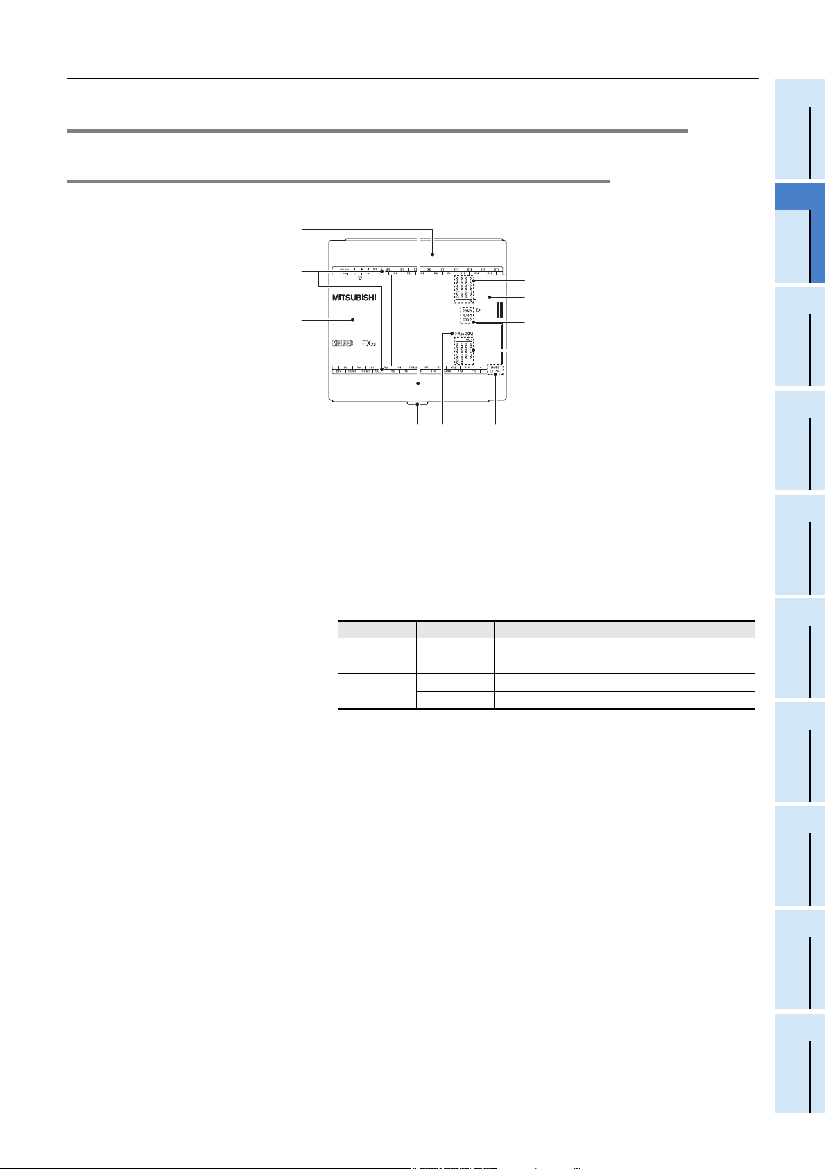
FX3S Series Programmable Controllers
LED name Display color Description
POW Green ON while power is on the PLC.
RUN Green ON while the PLC is running.
ERR
Red Flashing when a program error occurs.
Red Lights when a CPU error occurs.
User's Manual - Hardware Edition
2.2 Names and Functions of Parts
2.2.1 Front Panel
2 Features and Part Names
2.2 Names and Functions of Parts
1
Introduction
Factory default configuration (standard)
[3]
[2]
[1]
[1] Top cover Mount the expansion board, display module and memory cassette under this cover.
[2] Terminal names The signal names for power supply, input and output terminals are shown.
[3] Terminal block covers The covers can be opened for wiring.
[4] Input display LEDs (red) When an input terminal (X000 or more) is turned on, the corresponding LED lights.
[5] Peripheral device connecting
connector cover
[6] Operation status display LEDs The operation status of the PLC can be checked with the LEDs.
Keep the covers closed while the PLC is running (the unit power is on).
The peripheral device connector, variable analog potentiometers, analog inputs and RUN/
STOP switch are located under this cover.
The LEDs turn off, light and flash according to the following table.
For details on the operation status, refer to Section 14.5.
[4]
[5]
[6]
[7]
[8][9][10]
Devices
2
Features and
Part Names
3
Product
Introduction
4
Specifications
5
Version and
Peripheral
6
System
Configuration
[7] Output display LEDs (red) When an output terminal (Y000 or more) is turned on, the corresponding LED lights.
[8] The year and month of production The year and month of production of the main unit is indicated.
[9] Model name (abbreviation) The model name of the main unit is indicated.
[10] DIN rail mounting hooks The main unit can be installed on DIN46277 rail (35 mm (1.38") wide).
For details on the year and month of production,
Check the nameplate on the right side for the model name.
refer to Subsection 5.1.1.
21
7
Installation
8
Preparation and
Power Supply
Wiring
9
Input Wiring
10
High-Speed
Counters
Page 28
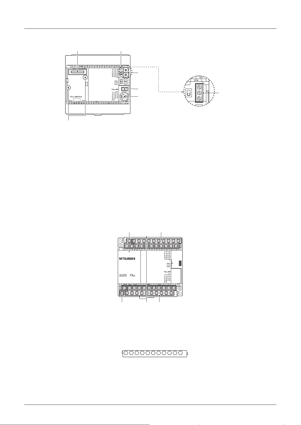
FX3S Series Programmable Controllers
[1]
[7]
[2]
[3]
[4]
[5]
[6]
[In the case of FX3S-30M□/E□-2AD]
User's Manual - Hardware Edition
When the top covers are open
2 Features and Part Names
2.2 Names and Functions of Parts
[1] Optional equipment connector These holes are designed to secure the expansion board, display module and memory
[2] RUN/STOP switch To stop writing (batch) of the sequence program or operation, set the switch to STOP (slide
[3] Variable analog potentiometers
(except FX3S-30M/E-2AD)
[4] Analog input terminal block
(only FX3S-30M/E-2AD)
[5] Peripheral device connecting
connector (USB)
[6] Peripheral device connecting
connector (RS-422)
[7] Optional equipment connecting
screw holes (2 places)
cassette with screws.
it downward).
To start operation (run the machine), set it to RUN (slide it upward).
Two variable analog potentiometers are built in.
Upper side: VR1, Lower side: VR2
Two analog inputs are built in.
These terminals are for wiring the analog inputs.
Connect a programming tool (PC) to program a sequence.
For details on applicable peripheral devices, refer to Chapter 5.
Connect a programming tool to program a sequence.
For details on applicable peripheral devices, refer to Chapter 5.
These holes are designed to secure the expansion board and memory cassette with screws.
When the terminal block covers are open
[2][1]
22
[5] [4]
[1] Power supply terminals Connect the power supply to the main unit.
[2] Input (X) terminals Wire switches and sensors to the terminals.
[3] Output (Y) terminals Wire loads (contactors, solenoid valves, etc.) to be driven to the terminals.
[4] Terminal cover A protective terminal cover (refer to the following drawing) is fitted to the lower stage of each
[5] Service power supply terminals
(only AC power type)
terminal block.
The cover prevents fingers from touching terminals, thereby improving safety.
Wire sensors or other external equipment to these terminals when the service power supply
(24 V DC) is used for such equipment.
[3]
Page 29
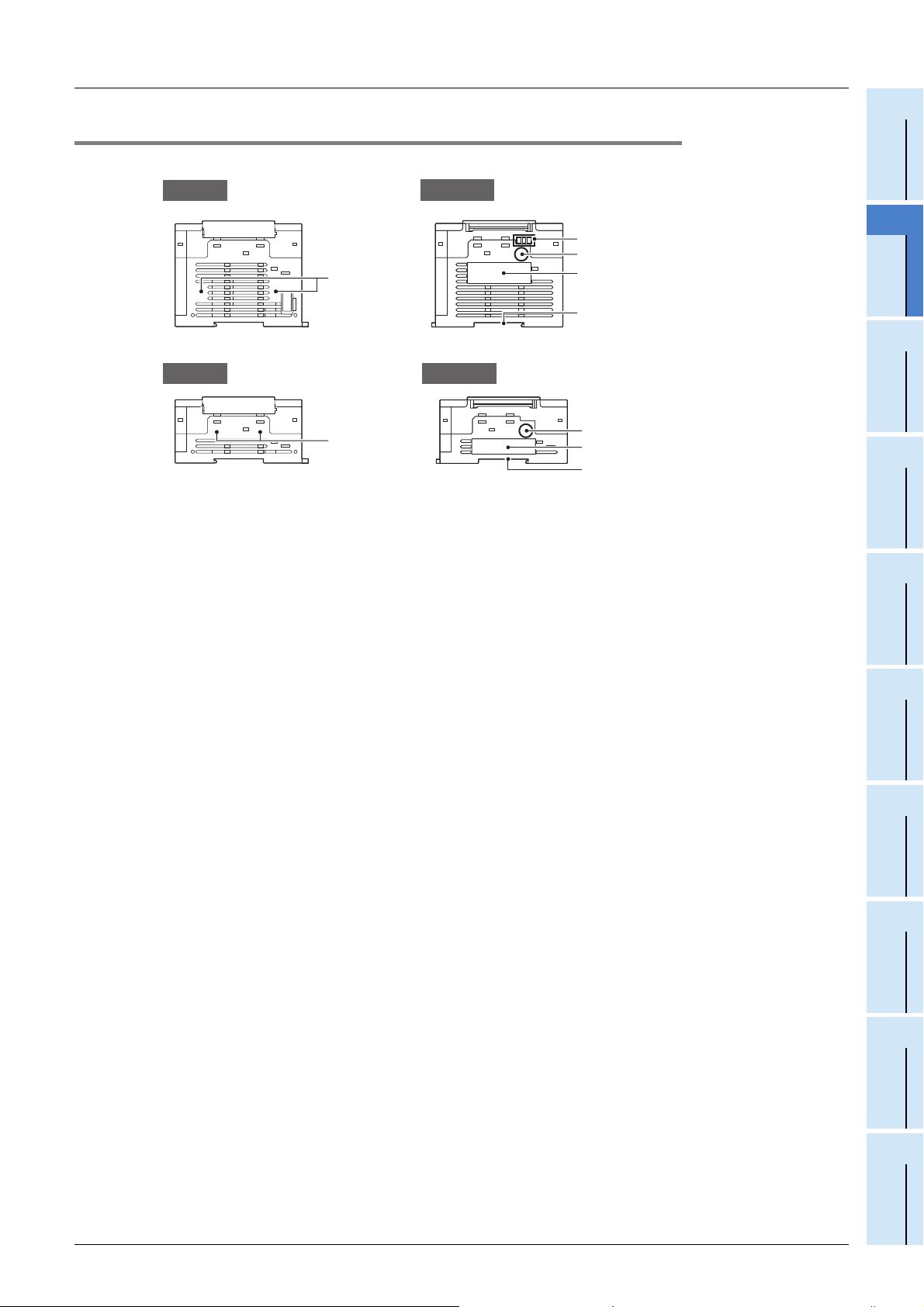
FX3S Series Programmable Controllers
[1]
Left side
[3]
[4]
[
5]
Right side
User's Manual - Hardware Edition
2.2.2 Sides
[AC Power Type]
2 Features and Part Names
2.2 Names and Functions of Parts
1
Introduction
Left side
[1]
[DC power type]
[1] Connector conversion adapter
connecting screw holes (2 places)
[2] Analog input terminal block
(only FX3S-30M/E-2AD)
[3]
Label of authenticity
[4] Nameplate The product model name, serial number and power supply specifications are shown.
[5] DIN rail mounting groove The unit can be installed on DIN46277 rail (35 mm (1.38") wide).
These holes are designed to secure the connector conversion adapter with screws.
Two analog inputs are built in.
These terminals are for wiring the analog inputs.
The label of authenticity is affixed to the right side of the product and indicates that the
product is genuine.
Product without the label or nameplate is not covered by the warranty.
Right side
[2]
[3]
[4]
5]
[
For details on the manufacturer's serial number,
refer to Subsection 5.1.1.
Devices
2
Features and
Part Names
3
Product
Introduction
4
Specifications
5
Version and
Peripheral
6
System
Configuration
7
Installation
8
Preparation and
Power Supply
Wiring
9
Input Wiring
10
High-Speed
Counters
23
Page 30
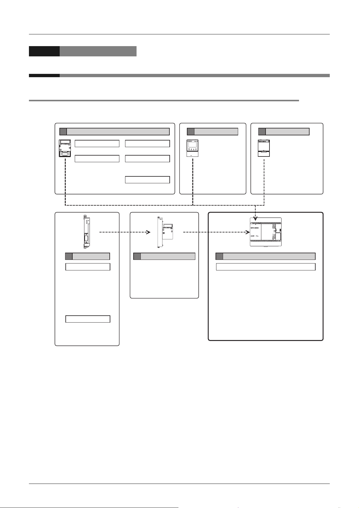
FX3S Series Programmable Controllers
User's Manual - Hardware Edition
3.1 List of Products and Interpretation of Model Names
3. Introduction of Products
3.1 List of Products and Interpretation of Model Names
The following system configuration is classified into product groups A to F in the product introduction sections
given below.
3 Introduction of Products
B
Expansion boards
• FX3G-4EX-BD • FX3G-2EYT-BD
Communication
3G-232-BD
• FX
• FX
3G-422-BD
• FX
3G-485-BD
• FX
3G-485-BD-RJ
Special adapters
D
Analog
• FX3U-4AD-ADP
• FX
3U-4DA-ADP
• FX
3U-3A-ADP
• FX
3U-4AD-PT-ADP
• FX
3U-4AD-PTW-ADP
• FX
3U-4AD-PNK-ADP
• FX
3U-4AD-TC-ADP
Communication
• FX
3U-232ADP (-MB)
• FX
3U-485ADP (-MB)
• FX
3U-ENET-ADP
OutputInput
Analog
3G-2AD-BD
• FX
• FX
3G-1DA-BD
Analog volume
3G-8AV-BD
• FX
Connector conversion adapter
C
3S-CNV-ADP
• FX
Display module
E
• FX3S-5DM
A
• FX
3S-10MR/ES
• FX
3S-14MR/ES
• FX
3S-20MR/ES
• FX
3S-30MR/ES
• FX
3S-30MR/ES-2AD
• FX
3S-10MR/DS
• FX
3S-14MR/DS
• FX
3S-20MR/DS
• FX
3S-30MR/DS
Memory cassette
F
• FX3G-EEPROM-32L
Main unit
Input/output
• FX
3S-10MT/ES(S)
• FX
3S-14MT/ES(S)
• FX
3S-20MT/ES(S)
• FX
3S-30MT/ES(S)
• FX
3S-30MT/ES(S)-2AD
• FX
3S-10MT/DS(S)
• FX
3S-14MT/DS(S)
• FX
3S-20MT/DS(S)
• FX
3S-30MT/DS(S)
24
Page 31

FX3S Series Programmable Controllers
FX
3S
M
Incorporating power supply •
CPU • memory • input/output
Power supply, Input/output type: Connection terminal block
• R/ES(-2AD)
• T/ES(-2AD)
• T/ESS(-2AD)
• R/DS
• T/DS
• T/DSS
Series name
Main unit
Total number of
input and output points
: AC power supply/24 V DC (sink/source) input/Relay output
: AC power supply/24 V DC (sink/source) input/Transistor (sink) output
: AC power supply/24 V DC (sink/source) input/Transistor (source) output
: DC power supply/24 V DC (sink/source) input/Relay output
: DC power supply/24 V DC (sink/source) input/Transistor (sink) output
: DC power supply/24 V DC (sink/source) input/Transistor (source) output
User's Manual - Hardware Edition
3.1.1 Main units
The main unit incorporates a CPU, memory, input and output terminals and power supply.
A
To establish a system, at least one main unit is necessary.
Number of input/output points
Model name
AC power supply common to 24 V DC sink and source input
FX3S-10MR/ES 10 6 4 24 V DC (sink/source) Relay Terminal block
FX3S-10MT/ES 10 6 4 24 V DC (sink/source) Transistor (sink) Terminal block
FX3S-10MT/ESS 10 6 4 24 V DC (sink/source) Transistor (source) Terminal block
FX3S-14MR/ES 14 8 6 24 V DC (sink/source) Relay Terminal block
FX3S-14MT/ES 14 8 6 24 V DC (sink/source) Transistor (sink) Terminal block
FX3S-14MT/ESS 14 8 6 24 V DC (sink/source) Transistor (source) Terminal block
FX3S-20MR/ES 20 12 8 24 V DC (sink/source) Relay Terminal block
FX3S-20MT/ES 20 12 8 24 V DC (sink/source) Transistor (sink) Terminal block
FX3S-20MT/ESS 20 12 8 24 V DC (sink/source) Transistor (source) Terminal block
FX3S-30MR/ES 30 16 14 24 V DC (sink/source) Relay Terminal block
FX3S-30MT/ES 30 16 14 24 V DC (sink/source) Transistor (sink) Terminal block
FX3S-30MT/ESS 30 16 14 24 V DC (sink/source) Transistor (source) Terminal block
FX3S-30MR/ES-2AD 30 16 14 24 V DC (sink/source) Relay Terminal block
FX3S-30MT/ES-2AD 30 16 14 24 V DC (sink/source) Transistor (sink) Terminal block
FX3S-30MT/ESS-2AD 30 16 14 24 V DC (sink/source) Transistor (source) Terminal block
DC power supply common to 24 V DC sink and source input
3S-10MR/DS 10 6 4 24 V DC (sink/source) Relay Terminal block
FX
FX3S-10MT/DS 10 6 4 24 V DC (sink/source) Transistor (sink) Terminal block
FX3S-10MT/DSS 10 6 4 24 V DC (sink/source) Transistor (source) Terminal block
FX3S-14MR/DS 14 8 6 24 V DC (sink/source) Relay Terminal block
FX3S-14MT/DS 14 8 6 24 V DC (sink/source) Transistor (sink) Terminal block
FX3S-14MT/DSS 14 8 6 24 V DC (sink/source) Transistor (source) Terminal block
FX
3S-20MR/DS 20 12 8 24 V DC (sink/source) Relay Terminal block
FX3S-20MT/DS 20 12 8 24 V DC (sink/source) Transistor (sink) Terminal block
FX3S-20MT/DSS 20 12 8 24 V DC (sink/source) Transistor (source) Terminal block
FX3S-30MR/DS 30 16 14 24 V DC (sink/source) Relay Terminal block
FX3S-30MT/DS 30 16 14 24 V DC (sink/source) Transistor (sink) Terminal block
FX3S-30MT/DSS 30 16 14 24 V DC (sink/source) Transistor (source) Terminal block
Total
number of
points
Number of
input
points
Number of
output
points
3 Introduction of Products
3.1 List of Products and Interpretation of Model Names
Input type Output type
Connection
form
1
Introduction
2
Features and
Part Names
3
Product
Introduction
4
Specifications
5
Version and
Peripheral
Devices
6
System
Configuration
7
Installation
8
Preparation and
Power Supply
Wiring
25
9
Input Wiring
10
High-Speed
Counters
Page 32

FX3S Series Programmable Controllers
User's Manual - Hardware Edition
3.1.2 Expansion boards
3 Introduction of Products
3.1 List of Products and Interpretation of Model Names
B
Model name Description
FX3G-4EX-BD
FX3G-2EYT-BD
FX3G-232-BD For RS-232C communication
FX3G-422-BD For RS-422 communication
FX3G-485-BD For RS-485 communication (European type)
FX3G-485-BD-RJ For RS-485 communication (RJ45 connector)
FX3G-8AV-BD For 8-ch analog volume
FX3G-2AD-BD 2-ch voltage/current input
FX3G-1DA-BD 1-ch voltage/current output
*1
4 points general-purpose input
*1
2 points transistor output
*1. Supported in FX3S PLC Ver. 1.10 or later.
3.1.3 Connector conversion adapter
C
Model name Description
FX3S-CNV-ADP Special adapter connection conversion adapter
3.1.4 Special adapters
D
Model name Description
FX3U-232ADP(-MB) For RS-232C communication
FX3U-485ADP(-MB) For RS-485 communication
*1
FX3U-ENET-ADP
FX3U-4AD-ADP 4-ch voltage/current input
FX3U-4DA-ADP 4-ch voltage/current output
FX3U-3A-ADP 2-ch voltage/current input 1-ch voltage/current output
FX3U-4AD-PT-ADP 4-ch platinum resistance thermometer sensor input (-50 to +250 C)
3U-4AD-PTW-ADP 4-ch platinum resistance thermometer sensor input (-100 to +600 C)
FX
FX
3U-4AD-PNK-ADP 4-ch Pt1000/Ni1000 resistance thermometer sensor input
3U-4AD-TC-ADP 4-ch thermocouple (K, J type) temperature sensor input
FX
For Ethernet communication
*1. The FX3U-ENET-ADP Ver. 1.20 or later is applicable to the FX3S PLC.
3.1.5 Display module
E
Model name Description
FX3S-5DM
*1
Display module that can be installed on FX3S Series main unit
*1. Supported in FX3S PLC Ver. 1.20 or later.
3.1.6 Memory cassette
F
26
Model name Description
3G-EEPROM-32L
FX
32k-step EEPROM memory (with transfer switch)
The FX
3S Series PLC can hold 16,000 steps of memory, but user program capacity is limited to 4,000 steps.
Page 33

FX3S Series Programmable Controllers
1
4
5
1
6
7
2
8
5
9
2
3
3
User's Manual - Hardware Edition
3.2 Connector Types and Cables for Program Communication
3 Introduction of Products
3.2 Connector Types and Cables for Program Communication
RS-232C/RS-422 cable
Connection cabling
Peripheral device connector
1
FX-30P
2
FX-232AWC-H
1
3
FX-20P-CAB0
RS-422RS-232C
2
Connection cabling for
extension device
1
Introduction
2
Features and
6
7
8
9
Part Names
3
Product
Introduction
USB
3
Special adapter
1
Expansion board
1
FX-30P
2
No. Shape of connector or combination with cable No. Shape of connector or combination with cable
D-SUB 9 Pin
4
3U
4
RS-232C
RS-232C
RS-232C RS-422
5
5
1
2
+ "FX-232AWC-H"
5
-232ADP(-MB)
FX
FX-232AWC-H
2
3
FX-20P-CAB0
"FX-422CAB0" + "F
FX-232CAB-1
1
2-232CAB-1"
FX3S-CNV-ADP
6
FX3G-232-BD
4
FX
3G
5
-422-BD
3G-232-BD D-SUB 9 Pin [RS-232C]
FX
FX
3U-232ADP(-MB) D-SUB 9 Pin [RS-232C]
3G-422-BD MINI DIN 8 Pin [RS-422]
FX
Devices
4
Specifications
5
Version and
Peripheral
6
System
Configuration
7
Installation
Half pitch 14 Pin
D-SUB 25 Pin
FX-30P MINI DIN
8 Pin [RS-422]
USB A connector
2
"FX-422CAB0" + "F
+ "FX-232AWC-H"
5
FX-232CAB-2
"FX-422CAB0" + "F2-232CAB"
+ "FX-232AWC-H"
F2-232CAB-1
FX-20P-CAB0
4
USB cable
Refer to Subsection 3.2.2.
1
2-232CAB-2"
FX3S-CNV-ADP
Expansion board connector
Peripheral device connector [RS-422]
MINI DIN 8 Pin
Peripheral device connector [USB]
Mini-B connector [USB 2.0]
27
8
Preparation and
Power Supply
Wiring
9
Input Wiring
10
High-Speed
Counters
Page 34

FX3S Series Programmable Controllers
1
2
3
4
5
4
1
1
1
5
5
2
3
User's Manual - Hardware Edition
3.2.1 Programming tool
The following programming tools support FX3S Series PLCs.
For more information, refer to 5. Version Information and Peripheral Equipment Connectability.
Model name Description
GX Works2 Version 1.492N or later of SWDNC-GXW2-E supports the FX3S.
FX-30P Version 1.50 or later of FX-30P supports the FX3S.
3.2.2 Communication cables
Model name Description
USB cable
3 m
USB cable
RS-232C cable
F2-232CAB-1
F2-232CAB
F2-232CAB-2
FX-232CAB-1
FX-232CAB-2
RS-422 cable
FX-422CAB0
FX-20P-CAB0
*1
USB A plug <-> USB Mini-B plug
(9’10")
For connection between personal computer and FX3S programming port (USB)
3 m
D-SUB 9 Pin <-> D-SUB 25 Pin
(9’10")
For connection between personal computer and RS-232C/RS-422 converter
3 m
D-SUB 25 Pin <-> D-SUB 25 Pin
(9’10")
For connection between personal computer and RS-232C/RS-422 converter
3 m
Half-pitch 14 Pin <-> D-SUB 25 Pin
(9’10")
For connection between personal computer and RS-232C/RS-422 converter
D-SUB 9 Pin <-> D-SUB 9 Pin
3 m
For connection between personal computer and RS-232C/RS-422 converter FX3G-232-BD,
(9’10")
FX3U-232ADP(-MB)
Half-pitch 14 Pin <-> D-SUB 9 Pin
3 m
For connection between personal computer and RS-232C/RS-422 converter FX3G-232-BD,
(9’10")
FX3U-232ADP(-MB)
D-SUB 25 Pin <-> MINI DIN 8 Pin
1.5 m
For connection between RS-232C/RS-422 converter and FX3S programming port (RS-422),
(4’11")
FX3G-422-BD
1.5 m
MINI DIN 8 Pin <-> MINI DIN 8 Pin
(4’11")
For connection between FX-30P and FX3S programming port (RS-422), FX3G-422-BD
3 Introduction of Products
3.2 Connector Types and Cables for Program Communication
*1. The following USB cables are applicable.
Model name Description
MR-J3USBCBL3M USB cable 3 m (9’10")
GT09-C30USB-5P USB cable to transfer personal computer data (USB A plug) 3 m (9’10")
3.2.3 Converters and interface
Model name Description
RS-232C/RS-422 converters
FX-232AWC-H
*2
*2. When the programming software is not applicable to FX3S or FX3G, the converter is applicable only to
9,600 or 19,200 bps.
RS-232C/RS-422 converter
Communication speed: Applicable to 9,600 to 115,200 bps.
28
Page 35

FX3S Series Programmable Controllers
PLC
Other
equipment
PLC
Other
equipment
PLC
Other
equipment
Shared grounding
Good condition
Common grounding
Not allowed
Independent grounding
Best condition
4 Specifications, External Dimensions and Terminal Layout (Main Units)
User's Manual - Hardware Edition
4. Specifications, External Dimensions and Terminal Layout (Main Units)
This chapter explains the specifications, external dimensions and terminal layout of the main units.
4.1 Generic Specifications
4.1 Generic Specifications
1
Introduction
2
Features and
Part Names
The generic specifications for the main unit are explained below.
Item Specification
Ambient temperature 0 to 55 °C (32 to 131 °F) when operating and -25 to 75 °C (-13 to 167 °F) when stored
Ambient humidity 5 to 95 %RH (no condensation) when operating
Frequency (Hz)
When installed on
*1
Vibration resistance
Shock resistance*1147 m/s2 Acceleration, Action time: 11 ms, 3 times by half-sine pulse in each direction X, Y, and Z
Noise resistance By noise simulator at noise voltage of 1,000 Vp-p, noise width of 1 s, rise time of 1 ns and period of 30 to 100 Hz
Dielectric withstand
voltage
Insulation resistance 5 M or more by 500 V DC megger
Grounding
Working atmosphere Free from corrosive or flammable gas and excessive conductive dust
Working altitude
DIN rail
When installed
directly
1.5 kV AC for 1 min
500 V AC for 1 min
Class D grounding (grounding resistance: 100 or less)
<Common grounding with a heavy electrical system is not allowed.>
*4
<2000 m
10 to 57 - 0.035
57 to 150 4.9 -
10 to 57 - 0.075
57 to 150 9.8 -
Acceleration (m/s2)
Between each terminals and ground terminal
Half amplitude (mm)
Sweep Count for
X, Y, Z: 10 times
(80 min in each
direction)
*2
*3
*1. The criterion is shown in IEC61131-2.
*2. For more information on the dielectric withstand voltage test and the insulation resistance test of the
terminals of each product, refer to the following.
Refer to Subsection 4.1.1.
*3. Ground the PLC independently or jointly.
Refer to Section 8.3.
Devices
3
Product
Introduction
4
Specifications
5
Version and
Peripheral
6
System
Configuration
7
Installation
*4. The PLC cannot be used at a pressure higher than the atmospheric pressure to avoid damage.
29
8
Preparation and
Power Supply
Wiring
9
Input Wiring
10
High-Speed
Counters
Page 36

FX3S Series Programmable Controllers
4 Specifications, External Dimensions and Terminal Layout (Main Units)
User's Manual - Hardware Edition
4.1.1 Dielectric withstand voltage test and insulation resistance test
Perform dielectric withstand voltage test and insulation resistance test at the following voltage between each
terminals and the main unit ground terminal.
Terminal Dielectric strength
Terminals of main unit
Between power supply terminal (AC power) and
ground terminal
Between power supply terminal (DC power) and
ground terminal
Between input terminal (24 V DC) and ground
terminal
Between output terminal (relay) and ground
terminal
Between output terminal (transistor) and ground
terminal
Main unit analog input terminal and ground
terminal
Terminals of expansion boards, special adapters
Between terminal of expansion board (except
3G-4EX-BD and FX3G-2EYT-BD) and ground
FX
terminal
Between FX
and ground terminal
Between FX3G-2EYT-BD output terminal
(transistor) and ground terminal
Between terminal of special adapter and ground
terminal
3G-4EX-BD input terminal (24 V DC)
1.5 kV AC for 1 min
500 V AC for 1 min
1.5 kV AC for 1 min -
500 V AC for 1 min -
Not allowed Not allowed -
Not allowed Not allowed
500 V AC for 1 min
Insulation
resistance
5 M or more by
500 V DC megger
Since the expansion board and the main
unit CPU are not insulated, it is not
allowed to perform the dielectric withstand
voltage test and insulation resistance test
between them.
5 M or more by
500 V DC megger
4.2 Power Supply Specifications
Remark
-
-
-
-
-
-
4.2 Power Supply Specifications
The power supply specifications for the main unit are explained below.
4.2.1 AC power type
Item
Supply voltage 100 to 240 V AC
Allowable supply voltage range 85 to 264 V AC
Rated frequency 50/60 Hz
Allowable instantaneous power
failure time
Power fuse 250 V 1 A
Rush current 15 A max. 5 ms or less/100 V AC, 28 A max. 5 ms or less/200 V AC
Power consumption
24 V DC service power supply 400 mA
*1
*1. This item shows values when all 24 V DC service power supplies are used in the maximum
configuration connectable to the main unit, and includes the input current (5 or 7 mA per point).
4.2.2 DC power type
Item
Supply voltage 24 V DC
Allowable supply voltage range 20.4 to 26.4 V DC
Allowable instantaneous power
failure time
Power fuse 250 V 1.6 A
Rush current 20 A max. 1 ms or less/24 V DC
Power consumption
24 V DC service power supply -
*2. There power consumption values are maximum values which include consumption of all expansion
equipment and input current (5 or 7 mA per point).
*2
FX3S-10M/E FX3S-14M/E FX3S-20M/E FX3S-30M/E
Operation can be continued upon occurrence of instantaneous power failure for 10 ms or less.
19 W 19 W 20 W 21 W
FX3S-10M/D FX3S-14M/D FX3S-20M/D FX3S-30M/D
Operation can be continued upon occurrence of instantaneous power failure for 5 ms or less.
6 W 6.5 W 7 W 8.5 W
Specification
Specification
30
Page 37

FX3S Series Programmable Controllers
24V
N
L
X
S/S
0V
Fuse
*1
*2
*2
100 to 240 V AC
24V
N
L
X
S/S
0V
100 to 240 V AC
Fuse
*1
*2
*2
X
S/S
Fuse
*1
24 V DC
User's Manual - Hardware Edition
4.3 Input Specifications
The input specifications for the main unit are explained below.
For the specifications of the built-in analog input, refer to Chapter 11.
4 Specifications, External Dimensions and Terminal Layout (Main Units)
4.3 Input Specifications
1
Introduction
4.3.1 24 V DC Input (sink/source)
For details on sink input and source input, refer to Subsection 9.1.1.
Item
Number of input points 6 points 8 points 12 points 16 points
Input connecting type Fixed terminal block (M3 screw)
Input form Sink/Source
Input signal voltage
Input impedance
Input signal
current
ON input
sensitivity current
OFF input sensitivity current 1.5 mA or less
Input response time Approx. 10 ms
Input signal form
Input circuit insulation Photocoupler insulation
Input operation display LED on panel lights when photocoupler is driven.
X000 to X007 3.3 k
X010 to X017 - 4.3 k
X000 to X007 7 mA/24 V DC
X010 to X017 - 5 mA/24 V DC
X000 to X007 4.5 mA or more
X010 to X017 - 3.5 mA or more
Sink input
Source input
• AC power type
Sink input wiring
Specification
FX3S-10M FX3S-14M FX3S-20M FX3S-30M
AC power type: 24 V DC ±10 %
DC power type: 20.4 to 26.4 V DC
No-voltage contact input
NPN open collector transistor
No-voltage contact input
PNP open collector transistor
Source input wiring
Devices
2
Features and
Part Names
3
Product
Introduction
4
Specifications
5
Version and
Peripheral
6
System
Configuration
Input circuit configuration
• DC power type
Sink input wiring
Fuse
24 V DC
S/S
*1
X
*1. Input impedance.
*2. The "24V" and "0V" terminals are located on the output terminal side.
For details on the terminal layout, refer to Section 4.7.
Source input wiring
31
7
Installation
8
Preparation and
Power Supply
Wiring
9
Input Wiring
10
High-Speed
Counters
Page 38

FX3S Series Programmable Controllers
User's Manual - Hardware Edition
4.4 Output Specifications
The output specifications for the main unit are explained below.
4.4.1 Relay output specifications
4 Specifications, External Dimensions and Terminal Layout (Main Units)
4.4 Output Specifications
Item
Number of output points 4 points 6 points 8 points 14 points
Output connecting type Fixed terminal block (M3 screw)
Output form Relay
External power supply
Resistance load
Max. load
Inductive load
Min. load 5 V DC, 2 mA (reference value)
Open circuit leakage current -
Response time
Output circuit insulation Mechanical insulation
Output operation display LED on panel lights when power is applied to relay coil.
Output circuit configuration
OFFON
ONOFF
FX3S-10MR FX3S-14MR FX3S-20MR FX3S-30MR
240 V AC or less (250 V AC or less when the unit does not comply with CE, UL or cUL standards.)
The total load current of resistance loads per common terminal should be the following value.
For details on the common terminal for each model, refer to the Section 4.7.
• 1 output point/common terminal: 2 A or less
• 4 output points/common terminal: 8 A or less
80 VA (UL and cUL standards approved at 120 and 240 V AC.)
Relay output specification
30 V DC or less,
2 A/point
For cautions on external wiring, refer to Subsection 12.1.3.
Load
DC power
supply
Fuse
Load
AC power
supply
Fuse
For the product life, refer to Subsection 14.4.2.
Approx. 10 ms
Y
COM
Y
COM
A common number applies to the of [COM ].
32
Page 39

FX3S Series Programmable Controllers
Load
Y
Fuse
DC power
supply
COM
A common number applies to the of
[COM ].
f
User's Manual - Hardware Edition
4.4.2 Transistor output specifications
4 Specifications, External Dimensions and Terminal Layout (Main Units)
4.4 Output Specifications
1
Introduction
Item
Number of output points 4 points 6 points 8 points 14 points
Output connecting type Fixed terminal block (M3 screw)
Output form
External power supply 5 to 30 V DC
Resistance load
Max. load
Inductive load
Open circuit leakage current 0.1 mA or less/30 V DC
ON voltage 1.5 V or less
Response time
Output circuit insulation Photocoupler insulation
Output operation display LED on panel lights when photocoupler is driven.
OFFON
ONOFF
FX3S-10MT FX3S-14MT FX3S-20MT FX3S-30MT
Transistor/sink output (FX3S-MT/S, FX3S-30MT/ES-2AD)
Transistor/source output (FX3S-MT/SS, FX3S-30MT/ESS-2AD)
The total load current of resistance loads per common terminal should be the following value.
• 1 output point/common terminal: 0.5 A or less
• 4 output points/common terminal: 0.8 A or less
The total of inductive loads per common terminal should be the following value.
• 1 output point/common terminal: 12 W or less/24 V DC
• 4 output points/common terminal: 19.2 W or less/24 V DC
Y000, Y001: 5 s or less/10 mA or more (5 to 24 V DC)
Y002 to Y015: 0.2 ms or less/200 mA or more (at 24 V DC)
Sink output wiring Source output wiring
Transistor output specification
0.5 A/point
For details on the common terminal for each model,
refer to the Section 4.7.
12 W/24 V DC
For details on the common terminal for each model,
refer to the Section 4.7.
Devices
2
Features and
Part Names
3
Product
Introduction
4
Specifications
5
Version and
Peripheral
Output circuit configuration
Load
DC power
supply
Fuse
A common number applies to the o
[+V ].
Y
+V
6
System
Configuration
7
Installation
8
Preparation and
Power Supply
Wiring
9
Input Wiring
10
High-Speed
Counters
33
Page 40

FX3S Series Programmable Controllers
User's Manual - Hardware Edition
4.5 Performance Specifications
The performance specifications for the main unit are explained below.
Item Performance
Operation control system Stored program repetitive operation system with interruption function.
Input/output control system
Programming language Relay symbol system + step-ladder system (SFC notation possible)
Built-in memory capacity/type
Program memory
Real-time clock
Kinds of instructions
Processing speed
Number of input/
output points
Input/output relay
Auxiliary relay
State
Timer
(on-delay timer)
Variable analog potentiometers
Analog inputs
Counter
Memory cassette (Option)
Writing function during running
Keyword function With keyword/Customer keyword function
Clock function
Basic instructions
Applied instructions 116 kinds
Basic instructions 0.21s/instruction
Applied instructions 0.5 s to several hundred s/instruction
Input points 16 points or less (Extension is impossible.)
Output points 14 points or less (Extension is impossible.)
Input relay X000 to X017
Output relay Y000 to Y015
For general M0 to M383 384 points
EEPROM keep M384 to M511 128 points
For general M512 to M1535 1024 points
For special M8000 to M8511 512 points
For initial state
(EEPROM keep)
EEPROM keep S10 to S127 118 points
For general S128 to S255 128 points
100 ms T0 to T31 32 points 0.1 to 3,276.7 sec
100 ms/10 ms T32 to T62 31 points
1 ms T63 to T127 65 points 0.001 to 32.767 sec
1 ms accumulating type T128 to T131 4 points 0.001 to 32.767 sec
100 ms accumulating type T132 to T137 6 points 0.1 to 3,276.7 sec
16 bits up (For general) C0 to C15 16 points Counting from 0 to 32,767
16 bits up (EEPROM keep) C16 to C31 16 points Counting from 0 to 32,767
32 bits up/down (For general) C200 to C234 35 points
*1
4 Specifications, External Dimensions and Terminal Layout (Main Units)
4.5 Performance Specifications
Batch processing system (when END instruction is executed)
Input/output refresh instruction and pulse catch function are provided.
16,000 steps/EEPROM memory (Program capacity is 4000 steps.)
Max. allowable write: 20,000 times
32,000 steps/EEPROM memory (with loader function)
The FX3S Series PLC is available only to 16,000 steps. (Program capacity is 4000
steps.)
Max. allowable write: 10,000 times
Provided (Program can be modified while the PLC is running.)
For the writing function during running, refer to Subsection 5.2.5.
Built-in
1980 to 2079 (with correction for leap year)
2- or 4-digit year, accuracy within 45 seconds/month at 25 °C
Sequence instructions: 29
Step-ladder instructions: 2
The device numbers are octal.
S0 to S9 10 points
0.1 to 3,276.7 sec/0.01 to 327.67 sec
When M8028 is driven ON, timers T32 to
T62 (31 points) are changed to 10 ms
resolution.
Available as analog timers
VR1: D8030 VR2: D8031
For compatible PLCs, refer to Chapter 11.
Available as voltage inputs
ch1: D8270 ch2: D8271
For compatible PLCs, refer to Chapter 11.
Counting from -2,147,483,648 to
+2,147,483,647
34
Page 41

FX3S Series Programmable Controllers
User's Manual - Hardware Edition
Item Performance
1-phase 1-count input in both
directions (32 bits up/down)
(EEPROM keep)
High-speed counter
Data register
(32 bits when
paired)
Pointer
Nesting For master control N0 to N7 8 points For MC instructions
Constant
*1. The current time of the clock is backed up by the capacitor built-in the PLC. Supply the power to the
PLC for 30 minutes or more to completely charge this large-capacity capacitor.
(The capacitor works for 10 days (atmosphere: 25 °C)
1-phase 2-count input in both
directions (32 bits up/down)
(EEPROM keep)
2-phase 2-count input in both
directions (32 bits up/down)
(EEPROM keep)
For general (16 bits) D0 to D127 128 points
For EEPROM keep (16 bits) D128 to D255 128 points
For general (16 bits) D256 to D2999 2744 points
File register
(EEPROM keep)
For special (16 bits) D8000 to D8511 512 points
For index (16 bits)
For branching of JUMP and
CALL
Input interruption I0 to I5 6 points
Timer interruption I6 to I8 3 points
Decimal number (K)
Hexadecimal number (H)
Real number (E) 32 bits
4 Specifications, External Dimensions and Terminal Layout (Main Units)
4.5 Performance Specifications
C235 to C245
C246 to C250
C251 to C255
D1000 to D2999 Max. 2000 points
V0 to V7
Z0 to Z7
P0 to P255 256 points
16 bits -32,768 to +32,767
32 bits -2,147,483,648 to +2,147,483,647
16 bits 0 to FFFF
32 bits 0 to FFFFFFFF
Counting from -2,147,483,648 to +2,147,483,647
Can be set as file registers in units of
500 points from D1000 in the program
area (EEPROM) using parameters.
16 points
For CJ instructions and CALL
instructions
128
-1.0 x 2
Decimal-point and exponential notations are possible.
to -1.0 x 2
-126
, 0 , 1.0 x 2
-126
to 1.0 x 2
128
Devices
1
Introduction
2
Features and
Part Names
3
Product
Introduction
4
Specifications
5
Version and
Peripheral
6
System
Configuration
7
Installation
8
Preparation and
Power Supply
Wiring
9
Input Wiring
10
High-Speed
Counters
35
Page 42

FX3S Series Programmable Controllers
W
Unit: mm (inches)
75 (2.96") : AC power type
49 (1.93") : DC power type
8 (0.32'')
90 (3.55'')
W1 (Mounting hole pitches)
2-4.5 mounting holes
82 (3.23'') (Mounting hole pitches)
User's Manual - Hardware Edition
4 Specifications, External Dimensions and Terminal Layout (Main Units)
4.6 External Dimensions (Weight/Accessories/Installation)
4.6 External Dimensions (Weight/Accessories/Installation)
The external dimensions of the main unit are explained.
4.6.1 Main units
Series Model name W: mm (inches)
FX3S-10MR/ES
FX3S-10M
FX3S-14M
3S-20M
FX
FX3S-30M
FX3S-10MT/ESS
FX3S-10MR/DS
FX3S-10MT/DSS
FX3S-14MR/ES
FX3S-14MT/ESS
FX3S-14MR/DS
FX3S-14MT/DSS
FX
3S-20MR/ES
FX3S-20MT/ESS
FX3S-20MR/DS
FX3S-20MT/DSS
FX3S-30MR/ES(-2AD)
FX3S-30MT/ESS(-2AD)
FX3S-30MR/DS
FX3S-30MT/DSS
W1: mm (inches)
Direct mounting hole pitches
60 (2.37”) 52 (2.05”)
60 (2.37”) 52 (2.05”)
75 (2.96”) 67 (2.64”)
100 (3.94”) 92 (3.63”)
MASS (Weight): kg (lbs)
Approx. 0.30 (0.66 lbs)FX3S-10MT/ES
Approx. 0.22 (0.48 lbs)FX3S-10MT/DS
Approx. 0.30 (0.66 lbs)FX3S-14MT/ES
Approx. 0.22 (0.48 lbs)FX3S-14MT/DS
Approx. 0.40 (0.88 lbs)FX3S-20MT/ES
Approx. 0.30 (0.66 lbs)FX3S-20MT/DS
Approx. 0.45 (0.99 lbs)FX3S-30MT/ES(-2AD)
Approx. 0.35 (0.77 lbs)FX3S-30MT/DS
36
1) Accessories
Dust proof protection sheet
Manual supplied with product
2) Installation
35 mm (1.38") wide DIN rail or Direct installation (with M4 screws)
Page 43

FX3S Series Programmable Controllers
X1S/S S/S
X0NLX2
X3X4X5X6X7
X10
X11
X12
X13
X14
X15
Y2Y0
COM1 COM2COM0
0V
24V Y3 Y5
Y7
Y10
COM4
Y14
Y15Y6 Y13
X16
X17
Y11Y1 Y4
COM3
Y12
S/S
FX
3S-30MR/ES, FX3S-30MT/ES
Input terminals
Partition
Common terminal
(4 points/common terminal)
24 V DC service
power supply
Power supply terminals
Output terminals
[•] Vacant terminal
(Do not use.)
Output terminals
connected to COM4
•
User's Manual - Hardware Edition
4.7 Terminal Layout
The terminal layout of the main unit are explained.
4 Specifications, External Dimensions and Terminal Layout (Main Units)
4.7 Terminal Layout
1
Introduction
4.7.1 Interpretation of terminal block layout
• Indication of power supply terminals
The AC power supply type has [L] and [N] terminals.
The DC power supply type has [ ] and [ ] terminals.
For external wiring, make sure to read the power supply wiring described later.
• Indication of 24 V DC service power supply
The AC power supply type has [0V] and [24V] terminals, whereas the DC power supply type shows [•]
since the DC power supply type does not have the service power supply.
[•] represents vacant terminals.
Do not connect with vacant terminals.
For external wiring, make sure to read the power supply wiring described later.
• Indication of input terminal
Both AC and DC power supply type have the same input terminals, however, the external input wiring
differs from each other.
For external wiring, make sure to read the input wiring described later.
• Indication of output terminals connected to common terminal
One common terminal covers 1 or 4 output points.
The output numbers (Y) connected to a common terminal are enclosed with heavy partition lines.
For transistor output (source) type, [COM] is [+V].
Refer to Chapter 8.
Refer to Chapter 8.
Refer to Chapter 9.
Devices
2
Features and
Part Names
3
Product
Introduction
4
Specifications
5
Version and
Peripheral
6
System
Configuration
7
Installation
37
8
Preparation and
Power Supply
Wiring
9
Input Wiring
10
High-Speed
Counters
Page 44

FX3S Series Programmable Controllers
User's Manual - Hardware Edition
4.7.2 FX3S-10M
• AC power type
4 Specifications, External Dimensions and Terminal Layout (Main Units)
4.7 Terminal Layout
S/SNLX1X2X3X4X5
FX
3S
-10MR/ES, FX3S-10MT/ES
0V
COM1 COM2COM0 COM3
FX
24V
3S
24V
-10MT/ESS
• DC power type
S/S X1X2X3X4X5
FX
3S
-10MR/DS, FX3S-10MT/DS
•
COM1 COM2COM0 COM3
FX
•
3S
•
-10MT/DSS
X0
Y2Y0
Y1
Y2Y0
Y1
+V1 +V2+V0 +V3
X0
Y2Y0
Y1
Y2Y0
Y1
+V1 +V2+V0 +V3
Y3
Y30V
Y3
Y3•
•
•
•
•
•
•
•
•
•
•
•
•
4.7.3 FX3S-14M
• AC power type
FX
3S
-14MR/ES, FX3S-14MT/ES
0V
24V
FX
3S
-14MT/ESS
0V
24V
• DC power type
FX
3S
-14MR/DS, FX3S-14MT/DS
•
•
S/SNLX1X2X3X4X5X6X7
X0
Y1
Y2Y0
COM1 COM2COM0
Y1
+V1 +V2+V0 Y3Y4Y5
S/S X1X2X3X4X5X6X7
X0
Y1
COM1 COM2COM0
Y3Y4Y5
Y2Y0
Y2Y0
Y3Y4Y5
•
•
•
38
FX
3S
•
-14MT/DSS
•
+V1 +V2+V0 Y3Y4Y5
Y1
Y2Y0
•
Page 45

FX3S Series Programmable Controllers
S/S X1X2X3X4X5X6X7
X10
X11
X12
X13
Y2Y0 Y3 Y6•Y1 Y4•
Y2Y0
COM1 COM2COM0 COM3Y3COM4
Y6
Y7Y5
•
•
Y1 Y4
X0
FX
3S-20MR/DS, FX3S-20MT/DS
+V1 +V2+V0 +V3 +V4 Y7Y5•
FX
3S-20MT/DSS
•
X1S/S S/S
X0 X2X3X4X5X6X7X10
X11
X12
X13
X14
X15
Y2Y0
COM1 COM2COM0
•
•Y3Y5
Y7
Y10
COM4
Y14
Y15Y6 Y13
X16
X17
Y11Y1 Y4
COM3
Y12
S/S
FX
3S-30MR/DS, FX3S-30MT/DS
Y2Y0
+V1 +V2+V0
•
•Y3Y5
Y7
Y10 +V4
Y14
Y15Y6 Y13
Y11Y1 Y4 +V3 Y12
FX
3S-30MT/DSS
•
•
User's Manual - Hardware Edition
4.7.4 FX3S-20M
• AC power type
4 Specifications, External Dimensions and Terminal Layout (Main Units)
4.7 Terminal Layout
1
Introduction
S/SNLX1X2X3X4X5X6X7
FX
3S-20MR/ES, FX3S-20MT/ES
0V
24V
3S-20MT/ESS
FX
• DC power type
X0
Y2Y0
Y1 Y4
COM1 COM2COM0 COM3Y3COM4
Y2Y0 Y3 Y60V Y1 Y4 •
+V1 +V2+V0 +V3 +V4 Y7Y524V
X10
X11
Y6
X12
Y7Y5
X13
•
Devices
2
Features and
Part Names
3
Product
Introduction
4
Specifications
5
Version and
Peripheral
4.7.5 FX3S-30M
• AC power type
FX
3S
-30MR/ES(-2AD), FX3S-30MT/ES(-2AD)
0V
24V Y3 Y5
FX
3S
-30MT/ESS(-2AD)
0V
24V Y3 Y5
• DC power type
COM1 COM2COM0
X1S/S S/S
X3X4X5X6X7
X0NLX2
S/S
COM3
+V1 +V2+V0
Y2Y0
Y2Y0
X11
X10
Y7
Y11Y1 Y4
Y10
Y7
Y11Y1 Y4 +V3 Y12
Y10 +V4
X12
COM4
X13
Y12
X14
X15
Y14
Y14
X16
Y15Y6 Y13
Y15Y6 Y13
X17
•
•
V1+
An analog input terminal is
V2+
built into FX
V-
3S
-30M□/E□-2AD.
6
System
Configuration
7
Installation
8
Preparation and
Power Supply
Wiring
9
Input Wiring
10
High-Speed
Counters
39
Page 46

FX3S Series Programmable Controllers
134
Year (Example: 2013): Last two digit of year
Month (Example: April):
1 to 9=January to September,
X=October, Y=November, Z=December
User's Manual - Hardware Edition
5 Version Information and Peripheral Equipment Connectability
5.1 Version Information
5. Version Information and Peripheral Equipment Connectability
5.1 Version Information
5.1.1 Manufacturer's serial number check method
The year and month of production of the product can be checked on the nameplate, and "LOT" indicated on
the front of the product.
1. Checking the name plate
The year and month of production of the product can be checked from the manufacturer's serial number S/N
indicated on the label adhered to the right side of the product.
Example nameplate
(manufacturer’s serial number: 1340001)
Right side
*
Actual product nameplate differs
from the example shown above.
314000
Month (Example: April):
1 to 9=January to September,
X=October, Y=November, Z=December
Year (Example: 2013): Last two digit of year
1
Control number
2. Checking the front of the product
The year and month of production of the product can be checked from the manufacturer's serial number
"LOT" on the front (at the bottom) of the product.
40
Page 47

FX3S Series Programmable Controllers
User's Manual - Hardware Edition
5.1.2 Version check method
The PLC version number can be checked by reading the last three digits of device D8001/D8101.
5 Version Information and Peripheral Equipment Connectability
5.2 Programming Tool Applicability
1
Introduction
D8001/D8101
PLC type and
version
2 8 1 0 0
Version information (Example: Ver. 1.00)
PLC type (Example: 28=FX
5.1.3 Version upgrade history
FX3S Series performed the following upgrade.
Version Manufacturer's serial number Contents of version upgrade
Ver. 1.00
Ver. 1.10
Ver. 1.20
133****
(March, 2013)
13X****
(October, 2013)
14X****
(October, 2014)
First product
•FX3S-30M/E-2AD (First product)
• Supports connection of following expansion boards:
FX3G-4EX-BD, FX3G-2EYT-BD
• Supports connection of display module (FX3S-5DM).
5.2 Programming Tool Applicability
5.2.1 Applicable versions of programming tool
1. GX Works2
GX Works2 is applicable to FX3S PLCs from the following versions.
FX3S PLC version Applicable GX Works2 version
Ver. 1.00 Ver. 1.492N or later
3S PLC)
Devices
2
Features and
Part Names
3
Product
Introduction
4
Specifications
5
Version and
Peripheral
6
System
Configuration
2. FX-30P
FX-30P is applicable to FX3S PLCs from the following version.
FX3S PLC version Applicable FX-30P version
Ver. 1.00 Ver. 1.50 or later
5.2.2 In the case of programming tool (version) not applicable
Inapplicable programming tools can be used by selecting an alternative PLC model.
1. Alternative model setting
Model to be programmed Model to be set Priority High Low
FX3S PLC
*1. "FX2N" is selected when the FX-10P(-E) is used.
2. Contents of restrictions
• Programming is enabled only in the function range such as instructions, device ranges and program sizes
available in both the FX
• When the FX-10P(-E) is used, the function range such as instructions, device ranges and program sizes is
limited to that available in both the FX
• Use a programming tool that can select either FX
register capacity, etc.
• Memory capacity must be set to 4000 steps or less.
• Use a programming tool that can select the FX
FX3S FX3G
3S PLC and the PLC selected as the alternative model.
3S PLC and the FX2N PLC.
3G to change parameters, i.e. memory capacity, file
3G model to program using the built-in USB port.
FX1N
7
Installation
8
Preparation and
Power Supply
*1
FX2N
*1
Wiring
9
10
Counters
Input Wiring
High-Speed
41
Page 48

FX3S Series Programmable Controllers
Leave this unchecked.
5 Version Information and Peripheral Equipment Connectability
User's Manual - Hardware Edition
5.2.3 Program transfer speed and programming tools
1. Built-in USB communication
The FX3S PLC has a built-in USB communication port, and performs program writing, program reading and
monitoring at high speed (12 Mbps) with a personal computer that supports USB.
1) Supported programming tools
GX Works2, GX Developer
2) In programming tools not supporting USB
Communication is performed via RS-422 or RS-232C.
2. RS-422/RS-232C communication
The FX3S PLC can write and read programs and perform monitoring at 115.2 kbps through RS-422/RS-232C
communication.
1) 115.2 kbps supported programming tools
GX Works2, GX Developer, FX-30P
2) 115.2 kbps supported interfaces
- Standard built-in port (RS-422) or expansion board FX
When the RS-232C/RS-422 converter FX-232AWC-H is connected.
- Expansion board FX
- Special adapter FX
3) In programming tools not supporting 115.2 kbps
Communication is executed at 9,600 or 19,200 bps.
*1. When the currently used programming tool does not support the FX
which allows selection of the FX
3G-232-BD for RS-232C
3U-232ADP(-MB) for RS-232C
*1
*1
3G-422-BD for RS-422
3G PLC as the alternative model.
5.2 Programming Tool Applicability
3S PLC, use a programming tool
5.2.4 Cautions on connecting peripheral equipment by way of expansion board or special adapter
When connecting peripheral equipment (programming tool or GOT [CPU direct connection]) by way of the
FX
3G-232-BD, FX3G-422-BD or FX3U-232ADP(-MB), set as follows. If the setting is not specified with the
status below, communication error may occur in the connected peripheral equipment.
For details, refer to the Data Communication Edition.
- Set to "K0" the special data register (D8120 or D8400) for communication format setting.
- Set the communication parameter "PLC system(2)" of the channel connecting the peripheral equipment
to "Not set" (as shown in the window below).
42
Page 49

FX3S Series Programmable Controllers
Added, deleted, or changed
Added, deleted, or changed
Step 0
I001
Pointer for
interrupt
Label I is inserted by editing the circuit block
FNC 04
EI
FNC 06
FEND
FNC 03
IRET
END
User's Manual - Hardware Edition
5.2.5 Cautions on write during RUN
Write during RUN (program changes during RUN) is available in the FX3S PLC when GX Works2 is used.
However, list programs and SFC programs cannot be written during RUN.
When programming software not supporting the FX
function range available in both the FX
Refer to the manual of the used programming software for the operations
Cautions on write during RUN
Item Caution
Program memories which can be written in
RUN mode
Number of program steps which can be written
for circuit change in RUN mode
Circuit blocks which cannot be written in RUN
mode
*1. Circuit blocks cannot be edited to insert a label as shown below when written during RUN.
5 Version Information and Peripheral Equipment Connectability
5.2 Programming Tool Applicability
3S PLC is used, write during RUN is available within the
3S PLC and the PLC selected as the alternative model.
for and cautions on write during RUN.
Built-in EEPROM and optional memory cassette (whose write protect switch is set to
OFF)
256 steps or less after edition (addition/deletion)
(including NOP immediately after circuit blocks except final circuit)
Circuit blocks*1 in which labels P and I are added, deleted or changed in edited circuits
Circuit blocks in which 1 ms timers (T63 to T131) are added in edited circuits
Circuit blocks in which the following instructions are included in edited circuits
• Instruction to output high-speed counters C235 to C255 (OUT instruction)
1
Introduction
2
Features and
Part Names
3
Product
Introduction
4
Specifications
5
Version and
Peripheral
Devices
6
System
Configuration
7
Installation
8
Preparation and
Power Supply
Wiring
43
9
Input Wiring
10
High-Speed
Counters
Page 50

FX3S Series Programmable Controllers
Contact ON/OFF status
(while write during RUN is executed)
Instruction for
rising edge pulse
Instruction for
falling edge pulse
OFF Not executed Not executed
ON
Executed
*1
Not executed
Operation result up to MEP/MEF instruction MEP instruction MEF instruction
OFF OFF (nonconducting) OFF (nonconducting)
ON ON (conducting) OFF (nonconducting)
User's Manual - Hardware Edition
Item Caution
Avoid write during RUN to a circuit block including the following instructions during execution.
If write during RUN is executed to such a circuit block, the PLC decelerates and stops pulse output.
• DSZR (FNC150), ZRN (FNC156), PLSV (FNC157) instructions [with acceleration/deceleration
operation], DRVI (FNC158) and/or DRVA (FNC159) instructions
Avoid write during RUN to a circuit block including the following instruction during execution.
If write during RUN is executed to such a circuit block, the PLC immediately stops pulse output.
• PLSV (FNC157) instruction [without acceleration/deceleration operation]
Avoid write during RUN to a circuit block including the following instructions during execution.
• PLSY (FNC 50), PWM (FNC 58) and/or PLSR (FNC 59) instructions
Avoid write during RUN to a circuit block including the following instructions during execution of
communication.
If write during RUN is executed to such a circuit block, the PLC may stop communication after that.
If the PLC stops communication, set the PLC to the STOP mode once, and then set it to the RUN
mode again.
• IVCK (FNC270), IVDR (FNC271), IVRD (FNC272), IVWR (FNC273), IVMC (FNC275) and
ADPRW (FNC276) instructions
• Instructions for falling edge pulse
When write during RUN is completed for a circuit including an instruction for falling edge pulse
(LDF, ANDF, or ORF instruction), the instruction for falling edge pulse is not executed without
regard to the ON/OFF status of the target device.
When write during RUN is completed for a circuit including an instruction for falling edge pulse
(PLF instruction), the instruction for falling edge pulse is not executed without regard to the ON/
OFF status of the device that is set as the operation condition.
It is necessary to set to ON the target device or operation condition device once and then set it
to OFF for executing the instruction for falling edge pulse.
Circuit blocks which require
attention on operation after write
during RUN
• Instructions for rising edge pulse
When write during RUN is completed for a circuit including an instruction for rising edge pulse,
the instruction for rising edge pulse is executed if a target device of the instruction for rising
edge pulse or the operation condition device is ON.
Target instructions for rising edge pulse: LDP, ANDP, ORP, and pulse operation type applied
instructions (such as MOVP)
5 Version Information and Peripheral Equipment Connectability
5.2 Programming Tool Applicability
Others
*1 The PLS instruction is not executed.
Writing in RUN mode to circuit blocks including the following instructions results in the following
operation
• MEP instruction (Conversion of operation result to leading edge pulse instruction)
When completing Write during RUN to a circuit including the MEP instruction, the execution
result of the MEP instruction turns ON (conducting state) if the operation result up to the MEP
instruction is ON.
• MEF instruction (Conversion of operation result to trailing edge pulse instruction)
When completing Write during RUN to a circuit including the MEF instruction, the execution
result of the MEF instruction turns OFF (nonconducting state) regardless of the operation result
(ON or OFF) up to the MEF instruction.
When the operation result up to the MEF instruction is set to ON once and then set to OFF, the
execution result of the MEF instruction turns ON (conducting state)
• When writing during RUN with GX Works2 the program is as follows.
When the number of program steps is reduced by deletion of contacts, coils and applied
instructions, the program capacity becomes smaller by as many as the reduced number of
steps.
• Errors cannot be detected in write during RUN even in a circuit which causes errors.
Errors are detected after the PLC is stopped once, and then run again.
44
Page 51

FX3S Series Programmable Controllers
Double-click it.
Select [USB]
5 Version Information and Peripheral Equipment Connectability
User's Manual - Hardware Edition
5.3 Use of (Built-in USB) Programming Port
Make sure to set the contents described in this section when executing circuit monitor, device monitor,
program reading/writing, etc. in the FX
3S PLC using the (built-in USB) programming port and GX Works2.
5.3 Use of (Built-in USB) Programming Port
1
Introduction
5.3.1 Installation of USB driver
It is necessary to install the USB driver to execute USB communication using the (built-in USB) programming
port.
For the USB driver installation method and procedure, refer to the following manual.
Refer to the GX Works2 Version 1 Operating Manual (Common)
5.3.2 Setting in GX Works2
1. Double-click the Connection Destination view [Connection Destination] [(Connection
target data name)] in the Navigation window of GX Works2.
The [Transfer Setup Connection1] is displayed.
2. Double-click [Serial USB] of the PC side I/F to display [PC side I/F Serial Setting].
3. Select [USB].
Devices
2
Features and
Part Names
3
Product
Introduction
4
Specifications
5
Version and
Peripheral
4. Click the [OK] button to finish the setting.
6
System
Configuration
7
Installation
8
Preparation and
Power Supply
Wiring
9
Input Wiring
45
10
High-Speed
Counters
Page 52

FX3S Series Programmable Controllers
Select [FXCPU]
Select
[via GOT[direct coupled] transparent mode]
User's Manual - Hardware Edition
5 Version Information and Peripheral Equipment Connectability
5.4 Cautions on using FA transparent function in GOT1000 Series
5.4 Cautions on using FA transparent function in GOT1000 Series
When monitoring circuits, device monitor, etc. or reading/writing programs in an FX3GC PLC from GX Works2
using the FA transparent function by way of USB in the GOT1000 Series, make sure to execute the following
setting.
1. Double-click the Connection Destination view [Connection Destination] [(Connection
target data name)] in the Navigation window of GX Works2.
The [Transfer Setup Connection1] is displayed.
2. Double-click [Serial USB] of the PC side I/F to display [PC side I/F Serial Setting].
3. Select [USB].
Double-click it.
Select [USB]
4. Double-click [GOT] of the PLC side I/F to display [PLC side I/F Detailed Setting of GOT].
5. Select [FXCPU], [via GOT[direct coupled] transparent mode].
6. Click the [OK] button to finish the setting.
46
Page 53

FX3S Series Programmable Controllers
Double-click it.
Put a check mark to the check box
[via GOT-F900 transparent mode]
Select [via GOT[direct coupled] transparent mode]
Select [FXCPU]
User's Manual - Hardware Edition
5.5 Cautions on using transparent port (2-port) function of GOT-F900 Series
5 Version Information and Peripheral Equipment Connectability
5.5 Cautions on using transparent port (2-port) function of GOT-F900
Series
When monitoring circuits, device monitor, etc. in an FX3S PLC from GX Works2 using the transparent (2-port)
function in the GOT-F900 Series, make sure to execute the following setting.
1. Double-click the Connection Destination view [Connection Destination] [(Connection
target data name)] in the Navigation window of GX Works2.
The [Transfer Setup Connection1] is displayed.
2. Double-click [Serial USB] of the PC side I/F to display [PC side I/F Serial Setting].
3. Select [RS-232C] in setting shown below, and set [COM port] and [Transmission Speed].
1
Introduction
2
Features and
Part Names
3
Product
Introduction
4
Specifications
4. Double-click [GOT] of the PLC side I/F to display [PLC side I/F Detailed Setting of GOT].
5. Select [FXCPU], [via GOT[direct coupled] transparent mode] in setting shown below and put
a check mark to the check box [via GOT-F900 transparent mode] .
5
Version and
Peripheral
Devices
6
System
Configuration
7
Installation
8
Preparation and
Power Supply
Wiring
6. Click the [OK] button to finish the setting.
47
9
Input Wiring
10
High-Speed
Counters
Page 54

FX3S Series Programmable Controllers
5 Version Information and Peripheral Equipment Connectability
User's Manual - Hardware Edition
5.6 Other Peripheral Equipment Applicability
5.6.1 Other peripheral equipment applicability
Model name Applicability Remarks
Standard monitor OS, communication driver and option OS which support the FX3S
PLC are required.
For details, refer to the GOT manual.
This series is subject to the following restrictions when connected using unsupported
standard monitor OS, communication driver or option OS.
Contents of restrictions
• When connected using standard monitor OS, communication driver and option
OS which support the FX3G PLC
- Programming is enabled only in the function range such as instructions,
GOT1000 Series Applicable
device ranges and program sizes available in both the FX3S PLC and the
FX3G PLC.
• When connected using standard monitor OS, communication driver and option
OS which do not support the FX3G PLC
- Programming is enabled only in the function range such as instructions,
device ranges and program sizes available in both the FX3S PLC and the
FX1N PLC.
- The list editor function for MELSEC-FX is not available. When using the list
editor function for MELSEC-FX, upgrade the standard monitor OS,
communication driver and option OS to the version compatible with the FX3S
PLC.
5.6 Other Peripheral Equipment Applicability
GOT-F900 Series Not available
FX-10DM(-SET0) Not available
Check the applicability of other items in the GOT manual.
The following restriction applies when connected.
Contents of restrictions
Programming is enabled only in the function range such as instructions, device
ranges and program sizes available in both the FX3S PLC and the FX1N PLC.
For applicable models, refer to the GOT manual.
For connection using the 2-port interface function, refer to Section 5.5.
The following restriction applies when connected.
Contents of restrictions
Programming is enabled only in the function range such as instructions, device
ranges and program sizes available in both the FX3S PLC and the FX1N PLC.
For supported models and device ranges, refer to the FX-10DM USER'S MANUAL
(Manual No. JY992D86401).
48
Page 55

FX3S Series Programmable Controllers
Connect a connector
conversion adapter to the
1st position of the BD slot.
The FX
3S
-5DM or
FX
3G
-EEPROM-32L
can be connected to the
2nd position.
BD 2nd position
BD 1st position
FX
3S
-5DM, FX3G-EEPROM-32L
When the 1st position is used by
an expansion board or connector
conversion adapter,
the FX
3G
-EEPROM-32L can be
connected to the 2nd position.
• FX
3G
-4EX-BD
• FX
3G
-232-BD
• FX
3G
-485-BD
• FX
3G
-2AD-BD
• FX
3G
-8AV-BD
• FX
3G
-EEPROM-32L
• FX
3G
-2EYT-BD
• FX
3G
-422-BD
• FX
3G
-485-BD-RJ
• FX
3G
-1DA-BD
• FX
3S
-5DM
User's Manual - Hardware Edition
6. Examination of System Configuration
6.1 Configuration of a Whole System
The configuration of a whole system is shown below as an example.
Configuration of a whole system
6 Examination of System Configuration
6.1 Configuration of a Whole System
1
Introduction
2
Features and
Part Names
Display module
Special adapters
Memory cassette
Connector conversion adapter
Expansion boards
Main unit
6.1.1 Expansion board/connector conversion adapter/memory cassette system configuration
One expansion board or connector conversion adapter, and one memory cassette can be connected.
The figure below shows the combination of each product and the available connection positions.
• 1st position: An expansion board, connector conversion adapter, display module or memory cassette can
be connected.
• 2nd position: A display module or memory cassette can be connected.
Devices
3
Product
Introduction
4
Specifications
5
Version and
Peripheral
6
System
Configuration
7
Installation
49
8
Preparation and
Power Supply
Wiring
9
Input Wiring
10
High-Speed
Counters
Page 56

FX3S Series Programmable Controllers
• FX3U-232ADP(-MB) • FX3U-485ADP(-MB)
• FX3U-ENET-ADP*
1
• FX3U-4AD-ADP
• FX3U-4DA-ADP • FX3U-3A-ADP
• FX
3U-4AD-PT-ADP • FX3U-4AD-PTW-ADP • FX3U-4AD-PNK-ADP
• FX
3U-4AD-TC-ADP
Analog
special adapter
Communication
special adapter
Connect a connector
conversion adapter.
Max. 1 unit
Max. 1 unit
User's Manual - Hardware Edition
Restrictions in the use of the FX3G-422-BD
When connecting a device (such as GOT) which consumes an internal 5 V DC to each of the RS-422 port
built in the main unit and the FX
3G-422-BD at the same time, avoid continuous use of either device.
If both devices are used continuously, their life may be shortened due to heat generation.
<Configuration example>
RS-422 port built-in main unit + GT1020LBL (5 V DC type)
3G-422-BD + GT1020LBL (5 V DC type)
FX
Avoid continuous use of two GT1020LBL (5 V DC type) units.
6.1.2 Special adapter system configuration
One special communication adapter and one special analog adapter can be connected.
A connector conversion adapter is required to use special adapters.
6 Examination of System Configuration
6.1 Configuration of a Whole System
*1. When using the FX
3U-ENET-ADP, connect it to the last adapter position (leftmost position).
50
Page 57

FX3S Series Programmable Controllers
User's Manual - Hardware Edition
7. Installation In Enclosure
DESIGN PRECAUTIONS
• Make sure to have the following safety circuits outside of the PLC to ensure safe system operation even during external power supply
problems or PLC failure.
Otherwise, malfunctions may cause serious accidents.
1) Most importantly, have the following: an emergency stop circuit, a protection circuit, an interlock circuit for opposite movements
(such as normal vs. reverse rotation), and an interlock circuit (to prevent damage to the equipment at the upper and lower
positioning limits).
2) Note that when the PLC CPU detects an error, such as a watchdog timer error, during self-diagnosis, all outputs are turned off.
Also, when an error that cannot be detected by the PLC CPU occurs in an input/output control block, output control may be
disabled.
External circuits and mechanisms should be designed to ensure safe machinery operation in such a case.
3) If an overload of the 24 V DC service power supply occurs, the voltage automatically drops, inputs in the PLC are disabled, and all
outputs are turned off.
External circuits and mechanisms should be designed to ensure safe machinery operation in such a case.
4) Note that when an error occurs in a relay or transistor output device, the output could be held either on or off.
For output signals that may lead to serious accidents, external circuits and mechanisms should be designed to ensure safe
machinery operation in such a case.
7 Installation In Enclosure
1
Introduction
2
Features and
Part Names
3
Product
Introduction
4
Specifications
DESIGN PRECAUTIONS
• Do not bundle the control line together with or lay it close to the main circuit or power line. As a guideline, lay the control line at least
100 mm (3.94") or more away from the main circuit or power line.
Noise may cause malfunctions.
• Install module so that excessive force will not be applied to peripheral device connectors.
Failure to do so may result in wire damage/breakage or PLC failure.
INSTALLATION PRECAUTIONS
• Make sure to cut off all phases of the power supply externally before attempting installation or wiring work.
Failure to do so may cause electric shock or damage to the product.
INSTALLATION PRECAUTIONS
• Use the product within the generic environment specifications described in Section 4.1 of this manual.
Never use the product in areas with excessive dust, oily smoke, conductive dusts, corrosive gas (salt air, Cl
flammable gas, vibration or impacts, or expose it to high temperature, condensation, or rain and wind.
If the product is used in such conditions, electric shock, fire, malfunctions, deterioration or damage may occur.
• Do not touch the conductive parts of the product directly.
Doing so may cause device failures or malfunctions.
• Install the product securely using a DIN rail or mounting screws.
• Install the product on a flat surface.
If the mounting surface is rough, undue force will be applied to the PC board, thereby causing nonconformities.
• Make sure to affix the expansion board with tapping screws.
Tightening torque should follow the specifications in the manual.
If the screws are tightened outside of the specified torque range, poor connections may cause malfunctions.
• When drilling screw holes or wiring, make sure that cutting and wiring debris do not enter the ventilation slits.
Failure to do so may cause fire, equipment failures or malfunctions.
• Be sure to remove the dust proof sheet from the PLC's ventilation port when installation work is completed.
Failure to do so may cause fire, equipment failures or malfunctions.
• Connect the peripheral device cables securely to their designated connectors.
Loose connections may cause malfunctions.
• Connect the display module, memory cassette and expansion board securely to their designated connectors.
Loose connections may cause malfunctions.
• Turn off the power to the PLC before attaching or detaching the following devices.
Failure to do so may cause device failures or malfunctions.
- Peripheral devices, display module, expansion boards, special adapters and memory cassette
• Connect the memory cassette securely to the appropriate connector.
Loose connections may cause malfunctions.
Installing the cassette in a raised or tilted posture can also cause malfunctions.
2, H2S, SO2 or NO2),
5
Version and
Peripheral
Devices
6
System
Configuration
7
Installation
8
Preparation and
Power Supply
Wiring
9
Input Wiring
10
High-Speed
Counters
51
Page 58

FX3S Series Programmable Controllers
User's Manual - Hardware Edition
WIRING PRECAUTIONS
• Make sure to cut off all phases of the power supply externally before attempting installation or wiring work.
Failure to do so may cause electric shock or damage to the product.
• Make sure to attach the terminal cover, offered as an accessory, before turning on the power or initiating operation after ins tallation or
wiring work.
Failure to do so may cause electric shock.
WIRING PRECAUTIONS
• Do not supply power to the [24V] terminal (24 V DC service power supply) on the main unit.
Doing so may cause damage to the product.
• Perform class D grounding (grounding resistance: 100 or less) to the grounding terminal on the main unit with a wire 2 mm2 or
thicker.
Do not use common grounding with heavy electrical systems (refer to Section 8.3).
• Connect the AC power supply wiring to the dedicated terminals described in this manual.
If an AC power supply is connected to a DC input/output terminal or DC power supply terminal, the PLC will burn out.
• Noise resistance may be lower when the L and N wires of an AC power supply are not wired correctly.
Please wire using the correct polarity.
• Connect the DC power supply wiring to the dedicated terminals described in this manual.
If an AC power supply is connected to a DC input/output terminal or DC power supply terminal, the PLC will burn out.
• Do not wire vacant terminals externally.
Doing so may damage the product.
• When drilling screw holes or wiring, make sure cutting or wire debris does not enter the ventilation slits.
Failure to do so may cause fire, equipment failures or malfunctions.
• Make sure to properly wire to the main unit in accordance with the following precautions.
Failure to do so may cause electric shock, equipment failures, a short-circuit, wire breakage, malfunctions, or damage to the product.
- Make sure to properly wire to the main unit in accordance with the rated voltage, current, and frequency of each terminal.
- The disposal size of the cable end should follow the dimensions described in the manual.
- Tightening torque should follow the specifications in the manual.
- Tighten the screws using a Phillips-head screwdriver No.2 (shaft diameter 6mm (0.24”) or less). Make sure that the screwdriver
does not touch the partition part of the terminal block.
• Make sure to properly wire to the terminal block (European type) in accordance with the following precautions.
Failure to do so may cause electric shock, equipment failures, a short-circuit, wire breakage, malfunctions, or damage to the product.
- The disposal size of the cable end should follow the dimensions described in the manual.
- Tightening torque should follow the specifications in the manual.
- Twist the end of strand wire and make sure that there are no loose wires.
- Do not solder-plate the electric wire ends.
- Do not connect more than the specified number of wires or electric wires of unspecified size.
- Affix the electric wires so that neither the terminal block nor the connected parts are directly stressed.
7 Installation In Enclosure
52
Page 59

FX3S Series Programmable Controllers
≥ 50 mm (1.97˝)
A
A
A
A
A
FX
3S Series
main unit
FX
3U
-4AD-ADP
FX
3S
-CNV-ADP
User's Manual - Hardware Edition
7.1 Installation location
Use the PLC under the environmental conditions complying with the generic specifications (Section 4.1).
• Keep a space of 50 mm (1.97") or more between the unit main body and another device or structure.
Install the unit as far away as possible from high-voltage lines, high-voltage devices and power equipment.
• To prevent temperature rise, do not install the PLC on a floor, a ceiling or a vertical surface.
Install it horizontally on a wall as shown in Subsection 7.1.1.
7.1.1 Installation location in enclosure
Notes
7 Installation In Enclosure
7.1 Installation location
1
Introduction
2
Features and
Part Names
3
Product
Introduction
4
Specifications
7.1.2 Space in enclosure
Special adapter can be connected on the left sides of the main unit.
If you intend to add special adapter in the future, keep necessary spaces on the left sides.
5
Version and
Peripheral
Devices
6
System
Configuration
7
Installation
8
Preparation and
Power Supply
Wiring
9
Input Wiring
53
10
High-Speed
Counters
Page 60

FX3S Series Programmable Controllers
User's Manual - Hardware Edition
7.2 Examination for Installing Method in Enclosure
7 Installation In Enclosure
7.2 Examination for Installing Method in Enclosure
Examine the installation location of PLC in consideration of the environmental conditions (generic
specifications).
The PLC can be installed by the following two methods.
1. Installing on DIN rail
• The PLC can be installed on a DIN46277 rail (35 mm (1.38") wide).
• The PLC can be easily moved and removed.
• The PLC is installed higher by the height of the DIN rail.
For details on the procedures on mounting and removing the DIN rail, refer to Section 7.3.
2. Direct installing (with screws)
• The PLC can be installed directly in the enclosure with M4 screws.
For the mounting hole pitch, refer to Section 7.4.
7.3 Procedures for Installing on and Detaching from DIN Rail
The main unit can be installed on a DIN46277 rail (35 mm (1.38") wide).
7.3.1 Preparation for installation
1. Connecting extension devices
Some extension devices must be mounted on the main unit before the unit is installed in the enclosure.
• Mount the special adapter or connector conversion adapter (FX
installing the main unit to the enclosure.
• The expansion boards, display module and memory cassette can be fitted to the main unit after it is
installed.
2. Affixing the dust proof sheet
The dust proof sheet should be affixed to the ventilation port before beginning the installation and wiring work
Be sure to remove the dust proof sheet when the installation and wiring work is completed.
For the affixing procedure, refer to the instructions on the dust proof sheet.
3S-CNV-ADP) on the main unit before
54
Page 61

FX3S Series Programmable Controllers
1
A
1
A
B
User's Manual - Hardware Edition
7.3 Procedures for Installing on and Detaching from DIN Rail
7.3.2 Installation of main unit
The main unit must be installed before installing a special adapter or connector conversion adapter (FX3S-
CNV-ADP) on the enclosure.
For the connection procedure, refer to Subsection 7.5.3 and Subsection 7.5.4.
Installation procedure
1 Push out all DIN rail mounting hooks (A in the
right figure).
7 Installation In Enclosure
1
Introduction
2
Features and
Part Names
3
Product
Introduction
4
Specifications
2 Fit the upper edge of the DIN rail mounting
groove (B in the right figure) onto the DIN rail.
B
3 Lock the DIN rail mounting hooks (C in the following figure) while pressing
the PLC against the DIN rail.
5
Version and
Peripheral
Devices
6
System
Configuration
7
Installation
8
Preparation and
Power Supply
Wiring
9
Input Wiring
C
3
10
High-Speed
Counters
55
Page 62

FX3S Series Programmable Controllers
A
User's Manual - Hardware Edition
7.3.3 Removal of main unit
Removal procedure
7.3 Procedures for Installing on and Detaching from DIN Rail
1 Open the terminal block cover, and remove the
lower terminal block cover (A in the right figure).
2 Disconnect the connecting cables (including
expansion board and special adapters).
3 Insert the tip of a flathead screwdriver into the
hole of the DIN rail mounting hook (B in the right
figure).
7 Installation In Enclosure
This step also applies for the DIN rail mounting hooks of the
special adapters.
4 Move the flathead screwdriver as shown in the
right figure to draw out the DIN rail mounting
hooks of all devices.
5 Remove the product from the DIN rail (C in the
right figure).
6 Push in the DIN rail mounting hooks (D in the
right figure).
C
B
3
D
6
5
4
56
Page 63

FX3S Series Programmable Controllers
B
98 (3.86˝)
W2.5 (0.1˝)
105 (4.18˝)
User's Manual - Hardware Edition
7.4 Procedures for Installing Directly (with M4 screws)
7.4 Procedures for Installing Directly (with M4 screws)
The product can be installed directly in the enclosure (with screws).
7 Installation In Enclosure
1
Introduction
7.4.1 Hole pitches for direct mounting
The product mounting hole pitches are shown below.
1. Main unit (A)
4 (0.16˝)
W
A
2. Special adapter (B)
4 (0.16˝)
90 (3.55˝)
82 (3.23˝)
4 (0.16˝)
Model name Mounting hole pitch (W)
FX3S-10MR/ES
FX3S-10MT/ES
FX3S-10MT/ESS
FX3S-10MR/DS
FX3S-10MT/DS
FX3S-10MT/DSS
FX3S-14MR/ES
FX3S-14MT/ES
FX3S-14MT/ESS
FX3S-14MR/DS
FX3S-14MT/DS
FX3S-14MT/DSS
A
FX3S-20MR/ES
FX3S-20MT/ES
FX3S-20MT/ESS
FX3S-20MR/DS
FX3S-20MT/DS
FX3S-20MT/DSS
FX3S-30MR/ES(-2AD)
FX3S-30MT/ES(-2AD)
FX3S-30MT/ESS(-2AD)
FX3S-30MR/DS
FX3S-30MT/DS
FX3S-30MT/DSS
Model name Mounting hole pitch (W)
3U-4AD-ADP
FX
FX
3U-4DA-ADP
FX3U-3A-ADP
3U-4AD-PT-ADP
FX
FX
B
3U-4AD-PTW-ADP
FX3U-4AD-PNK-ADP
3U-4AD-TC-ADP
FX
FX
3U-232ADP(-MB)
FX3U-485ADP(-MB)
FX3U-ENET-ADP 20.5 (0.81″)
Unit: mm (inches)
52 (2.05")
67 (2.64")
92 (3.63")
Unit: mm (inches)
15.1 (0.6")
2
Features and
Part Names
3
Product
Introduction
4
Specifications
5
Version and
Peripheral
Devices
6
System
Configuration
7
Installation
8
Preparation and
Power Supply
Wiring
9
Input Wiring
57
10
High-Speed
Counters
Page 64

FX3S Series Programmable Controllers
User's Manual - Hardware Edition
7.4.2 Example of mounting hole pitches
The figure below shows an example when the FX3S-30MT/ES, FX3S-CNV-ADP and FX3U-232ADP(-MB) are
used.
15.1
(0.6˝)
-232ADP (-MB)
3U
FX
18.6
(0.74˝)
FX3S-30MT/ES
-CNV-ADP
3S
FX
Unit: mm (inches)92 (3.63˝)
82 (3.23˝)
98 (3.86˝)
7.4.3 Installation of main unit
Mount the special adapters and connector conversion adapter (FX3S-CNV-ADP) on the main unit before
installing the unit in the enclosure.
For the connection procedure, refer to Subsection 7.5.3 and Subsection 7.5.4.
7 Installation In Enclosure
7.5 Connecting Methods for Main Unit and Extension Devices
Installation procedure
1 Make mounting holes in the mounting surface
according to the external dimensions diagram.
B
2 Fit the main unit (A in the right figure) based on the
holes, and secure it with M4 screws (B in the right
figure).
The positions of screws, refer to Subsection 7.4.1.
A
7.5 Connecting Methods for Main Unit and Extension Devices
This section explains the connecting methods for extension devices.
7.5.1 Connection of extension devices
This subsection explains the method for connecting the main unit, expansion board, connector conversion
adapter and special adapters using the connection configuration example shown below.
B
58
Example of configuration
Special
adapter
Connecting
method C
Connector
conversion
adapter
FX3S Series
Connecting
method B
Expansion
board
main unit
Connecting
method A
For the connection method A, refer to Subsection 7.5.2.
For the connection method B, refer to Subsection 7.5.3.
For the connection method C, refer to Subsection 7.5.4.
Page 65

FX3S Series Programmable Controllers
A
1
User's Manual - Hardware Edition
7.5 Connecting Methods for Main Unit and Extension Devices
7.5.2 Connecting method A - connection of expansion board
This subsection explains how to connect the expansion board to the main unit.
Connection procedure
1 Remove the top cover (A in the right
figure) from the front face of the main unit.
2 Connect the expansion board to the
option connector (B in the right figure).
7 Installation In Enclosure
1
Introduction
2
Features and
Part Names
3
Product
Introduction
4
B
2
Specifications
3 Fix the expansion board (D in the right
figure) to the main unit with M3 tapping
screws (C in the right figure) supplied as
accessories of the expansion board.
• Tightening torque: 0.3 to 0.6 N•m
5
Version and
Peripheral
Devices
C
D
6
System
Configuration
7
Installation
8
Preparation and
Power Supply
Wiring
9
Input Wiring
10
High-Speed
Counters
59
Page 66

FX3S Series Programmable Controllers
A
1
B
C
E
D
4
F
4
F
User's Manual - Hardware Edition
7.5.3 Connecting method B - connection of connector conversion adapter
This subsection explains how to connect the connector conversion adapter to the main unit.
Connection procedure
7.5 Connecting Methods for Main Unit and Extension Devices
7 Installation In Enclosure
1 Remove the top cover (A in the right
figure) from the front face of the main unit.
2 Connect the connector conversion
adapter (board) to the option connector
(B in the right figure) as shown in the right
figure, and fix it with M3 tapping screws
(C in the right figure) supplied as
accessories of the connector conversion
adapter.
• Tightening torque: 0.3 to 0.6 N•m
Proceed to the step 4 when using the AC power type
main unit.
Proceed to the step 3 when using the DC power type
main unit.
3 Attach the connector cover provided on
the DC power type connector (D in the
right figure) to the AC power type
connector (E in the right figure).
4 Connect the connector conversion adapter (main body) to the connector
(F in the follow figure) provided on the connector conversion adapter (board)
as shown in the follow figure.
[In the case of AC power type main unit] [In the case of DC power type main unit]
60
Page 67

FX3S Series Programmable Controllers
G
G
A
3
2
2
2
3
A
B
User's Manual - Hardware Edition
7.5 Connecting Methods for Main Unit and Extension Devices
7 Installation In Enclosure
5 Fix the connector conversion adapter (main body) to the main unit with M3
tapping screws (G in the follow figure) supplied as accessories of the
connector conversion adapter.
• Tightening torque: 0.3 to 0.6 N•m
Caution
Mounting holes to be used vary depending on the power type of the main unit.
Make sure to connect the connector conversion adapter (main body) using the proper mounting holes. The
main unit may be damaged if the proper mounting holes are not used.
1
Introduction
2
Features and
Part Names
[In the case of AC power type main unit] [In the case of DC power type main unit]
7.5.4 Connecting method C - connection of special adapter
This subsection explains how to connect the special adapter to the main unit.
When connecting the special adapter, it is necessary to attach the connector conversion adapter before the
special adapter using the method described in the preceding subsection.
Connection procedure
1 Slide the special adapter connecting hooks
(A in the right figure) of the main unit.
When adding a special adapter to the special adapter
that has been connected to the connector conversion
adapter, read "connector conversion adapter" as
"special adapter." (This applies to the following steps.)
3
Product
Introduction
4
Specifications
5
Version and
Peripheral
Devices
6
System
Configuration
1
A
1
7
Installation
A
2 Connect the special adapter (B in
8
Preparation and
Power Supply
Wiring
the right figure) to the connector
conversion adapter as shown in the
right figure.
9
3 Slide the special adapter connecting
Input Wiring
hooks (A in the right figure) of the
connector conversion adapter to
secure the special adapter (B in the
right figure).
61
10
High-Speed
Counters
Page 68

FX3S Series Programmable Controllers
When the memory cassette
is not used together
When the memory cassette
is used together
when the memory cassette
is not used together
when the memory cassette
is used together
User's Manual - Hardware Edition
7.6 Application of labels
The label is packed together with the expansion board (FX3G-485-BD, FX3G-485-BD-RJ, FX3G-8AV-BD).
Place it in a position where it can be seen easily for simple reference.
7.6.1 Application of Station No. label (FX3G-485-BD)
The station No. label is packed together with the FX3G-485-BD.
Place it in a position where it can be seen easily for simple reference (as shown in the figure below).
7 Installation In Enclosure
7.6 Application of labels
7.6.2 Application of Station No. label (FX3G-485-BD-RJ)
The "station No." label is packed together with the FX3G-485-BD-RJ.
Place it in a position where it can be seen easily for simple reference (as shown in the figure below).
62
Page 69

FX3S Series Programmable Controllers
User's Manual - Hardware Edition
7.6.3 Application of trimmer layout Label (FX3G-8AV-BD)
The trimmer layout label is packed together with the FX3G-8AV-BD.
Adhere it in a position where it can be seen easily for quick reference (as shown in the figure below).
7 Installation In Enclosure
7.6 Application of labels
1
Introduction
2
Features and
Part Names
3
Product
Introduction
4
Specifications
5
Version and
Peripheral
Devices
6
System
Configuration
7
Installation
8
Preparation and
Power Supply
Wiring
63
9
Input Wiring
10
High-Speed
Counters
Page 70

FX3S Series Programmable Controllers
8 Preparation for Wiring and Power Supply Wiring Procedures
User's Manual - Hardware Edition
8. Preparation for Wiring and Power Supply Wiring Procedures
DESIGN PRECAUTIONS
• Make sure to have the following safety circuits outside of the PLC to ensure safe system operation even during external power supply
problems or PLC failure.
Otherwise, malfunctions may cause serious accidents.
1) Most importantly, have the following: an emergency stop circuit, a protection circuit, an interlock circuit for opposite movements
(such as normal vs. reverse rotation), and an interlock circuit (to prevent damage to the equipment at the upper and lower
positioning limits).
2) Note that when the PLC CPU detects an error, such as a watchdog timer error, during self-diagnosis, all outputs are turned off.
Also, when an error that cannot be detected by the PLC CPU occurs in an input/output control block, output control may be
disabled.
External circuits and mechanisms should be designed to ensure safe machinery operation in such a case.
3) If an overload of the 24 V DC service power supply occurs, the voltage automatically drops, inputs in the PLC are disabled, and all
outputs are turned off.
External circuits and mechanisms should be designed to ensure safe machinery operation in such a case.
4) Note that when an error occurs in a relay or transistor output device, the output could be held either on or off.
For output signals that may lead to serious accidents, external circuits and mechanisms should be designed to ensure safe
machinery operation in such a case.
DESIGN PRECAUTIONS
• Do not bundle the control line together with or lay it close to the main circuit or power line. As a guideline, lay the control line at least
100 mm (3.94") or more away from the main circuit or power line.
Noise may cause malfunctions.
• Install module so that excessive force will not be applied to peripheral device connectors.
Failure to do so may result in wire damage/breakage or PLC failure.
64
Page 71

FX3S Series Programmable Controllers
User's Manual - Hardware Edition
WIRING PRECAUTIONS
• Make sure to cut off all phases of the power supply externally before attempting installation or wiring work.
Failure to do so may cause electric shock or damage to the product.
• Make sure to attach the terminal cover, offered as an accessory, before turning on the power or initiating operation after ins tallation or
wiring work.
Failure to do so may cause electric shock.
WIRING PRECAUTIONS
8 Preparation for Wiring and Power Supply Wiring Procedures
1
Introduction
2
Features and
Part Names
• Do not supply power to the [24V] terminal (24 V DC service power supply) on the main unit.
Doing so may cause damage to the product.
• Perform class D grounding (grounding resistance: 100 or less) to the grounding terminal on the main unit with a wire 2 mm2 or
thicker.
Do not use common grounding with heavy electrical systems (refer to Section 8.3).
• Connect the AC power supply wiring to the dedicated terminals described in this manual.
If an AC power supply is connected to a DC input/output terminal or DC power supply terminal, the PLC will burn out.
• Noise resistance may be lower when the L and N wires of an AC power supply are not wired correctly.
Please wire using the correct polarity.
• Connect the DC power supply wiring to the dedicated terminals described in this manual.
If an AC power supply is connected to a DC input/output terminal or DC power supply terminal, the PLC will burn out.
• Do not wire vacant terminals externally.
Doing so may damage the product.
• When drilling screw holes or wiring, make sure cutting or wire debris does not enter the ventilation slits.
Failure to do so may cause fire, equipment failures or malfunctions.
• Make sure to properly wire to the main unit in accordance with the following precautions.
Failure to do so may cause electric shock, equipment failures, a short-circuit, wire breakage, malfunctions, or damage to the product.
- Make sure to properly wire to the main unit in accordance with the rated voltage, current, and frequency of each terminal.
- The disposal size of the cable end should follow the dimensions described in the manual.
- Tightening torque should follow the specifications in the manual.
- Tighten the screws using a Phillips-head screwdriver No.2 (shaft diameter 6mm (0.24”) or less). Make sure that the screwdriver
does not touch the partition part of the terminal block.
• Make sure to properly wire to the terminal block (European type) in accordance with the following precautions.
Failure to do so may cause electric shock, equipment failures, a short-circuit, wire breakage, malfunctions, or damage to the product.
- The disposal size of the cable end should follow the dimensions described in the manual.
- Tightening torque should follow the specifications in the manual.
- Twist the end of strand wire and make sure that there are no loose wires.
- Do not solder-plate the electric wire ends.
- Do not connect more than the specified number of wires or electric wires of unspecified size.
- Affix the electric wires so that neither the terminal block nor the connected parts are directly stressed.
Devices
3
Product
Introduction
4
Specifications
5
Version and
Peripheral
6
System
Configuration
7
Installation
65
8
Preparation and
Power Supply
Wiring
9
Input Wiring
10
High-Speed
Counters
Page 72

FX3S Series Programmable Controllers
User's Manual - Hardware Edition
8.1 Preparation for Wiring
8.1.1 Wiring procedures
Before starting wiring work, make sure that the main power is off.
1 Prepare the parts for wiring.
Prepare the solderless terminals and cables necessary for wiring.
2 Wire the power supply terminals.
In the case of AC power type
• Connect the power supply to the terminals [L] and [N].
In the case of DC power type
• Connect the power supply to the terminals [ ] and [ ].
Provide the power supply circuit with the protection circuit shown in this subsection.
8 Preparation for Wiring and Power Supply Wiring Procedures
8.1 Preparation for Wiring
For details, refer to Section 8.2.
For details, refer to Section 8.4.
3 Wire the ground terminal [ ] at a grounding resistance of 100or less
(Class D).
Connect a class D ground wire to the terminal.
For details, refer to Section 8.3 and Section 8.4.
4 Wire the input [X] terminals.
For input, select sink or source input by the following connection.
In the case of AC power type
• For sink input, connect the [24V] and [S/S] terminals.
• For source input, connect the [0V] and [S/S] terminals.
In the case of DC power type
• For sink input, connect the [ ] and [S/S] terminals.
• For source input, connect the [ ] and [S/S] terminals.
Connect sensors and switches to the terminals.
For details, refer to Chapter 9.
5 Wire the output [Y] terminals.
Connect loads to the terminals.
For details, refer to Chapter 12.
66
Page 73

FX3S Series Programmable Controllers
Terminal
Terminal
screw
Crimp
terminal
6.2 mm (0.24˝)
or less
3.2 (0.13˝)
6.2 mm (0.24˝)
or less
3.2 (0.13˝)
Terminal
Terminal
screw
Crimp
terminal
6.2 mm (0.24˝)
or less
3.2 (0.13˝)
6.3 mm (0.25˝)
or more
6.3 mm (0.25˝)
or more
6.2 mm (0.24˝)
or less
3.2 (0.13˝)
User's Manual - Hardware Edition
8.2 Cable Connecting Procedures
The cable connecting procedures are explained below.
8 Preparation for Wiring and Power Supply Wiring Procedures
8.2 Cable Connecting Procedures
1
Introduction
8.2.1 Terminal block [Main unit]
The terminal block of main unit is the M3 screw.
For the terminal block of a built-in analog input, refer to Chapter 11.
1. Terminal block screw size and tightening torque
The terminal block screw and tightening torque is shown below.
Product Terminal screw Tightening torque
Main unit M3 0.5 to 0.8 N•m
2. Wire end treatment
The solderless terminal size depends on the terminal screw size and wiring method.
- Use solderless terminals of the following size.
- Tighten the terminals to a torque of 0.5 to 0.8 N•m.
Do not tighten terminal screws with a torque outside the above-mentioned range. Failure to do so may
cause equipment failures or malfunctions.
• When one wire is connected to one terminal
Devices
2
Features and
Part Names
3
Product
Introduction
4
Specifications
5
Version and
Peripheral
<Reference>
Terminal Manufacturer Type No. Certification Pressure Bonding Tool
JAPAN SOLDERLESS TERMINAL
MFG CO LTD (JST)
• When two wires are connected to one terminal
<Reference>
Terminal Manufacturer Type No. Certification Pressure Bonding Tool
JAPAN SOLDERLESS TERMINAL
MFG CO LTD (JST)
FV1.25-B3A
FV2-MS3
FV1.25-B3A UL Listed YA-1(JST)
UL Listed YA-1(JST)
6
System
Configuration
7
Installation
8
Preparation and
Power Supply
Wiring
9
Input Wiring
67
10
High-Speed
Counters
Page 74

FX3S Series Programmable Controllers
9 mm
(0.36˝)
• Stranded wire/solid wire
• Bar terminal with insulating sleeve
8 mm
(0.32˝)
Contact area
(Crimp area)
14 mm (0.56˝)
2.6 mm
(0.11˝)
Insulating sleeve
User's Manual - Hardware Edition
8 Preparation for Wiring and Power Supply Wiring Procedures
8.2 Cable Connecting Procedures
8.2.2 Terminal block (for European) [expansion board and special adapters]
The expansion boards and special adapters of a terminal block type have terminal blocks for European.
1. Applicable products
Classification Model name
Expansion board FX3G-4EX-BD, FX3G-2EYT-BD, FX3G-485-BD, FX3G-2AD-BD, FX3G-1DA-BD
Special adapters
2. Compliant electric wires and tightening torque
One electric wire
Two electric wires
Bar terminal with
insulating sleeve
FX3U-485ADP(-MB), FX3U-4AD-ADP, FX3U-4DA-ADP, FX3U-3A-ADP, FX3U-4AD-PT-ADP, FX3U-4AD-PTW-ADP,
FX3U-4AD-PNK-ADP, FX3U-4AD-TC-ADP
Electric wire size
(stranded wire/solid wire)
0.3 to 0.5 mm
(AWG 22 to 20)
0.3 mm2 (AWG 22)2
0.3 to 0.5 mm
(AWG 22 to 20)
(Refer to the following outline
drawing of bar terminal.)
2
2
Tightening
torque
0.22 to 0.25 N•m
End treatment
• Remove the coating of the stranded wire, twist the core
wires, and connect the wires directly.
• Remove the coating from the solid wire, and connect the wire
directly.
• Bar terminal with insulating sleeve (recommended product)
AI 0.5-8WH: Phoenix Contact
• Caulking tool
CRIMPFOX 6*1: Phoenix Contact
(CRIMPFOX 6T-F*2: Phoenix Contact)
*1. Old model name: CRIMPFOX ZA 3
*2. Old model name: CRIMPFOX UD 6
3. Treatment of electric wire ends
Treat the ends of stranded wires and solid wires without coating or using bar terminals with insulating sleeve.
Tighten the terminals to a torque of 0.22 to 0.25 N•m.
Do not tighten terminal screws with a torque outside the above-mentioned range. Failure to do so may cause
equipment failures or malfunctions.
• Treatment of stranded wires and solid wires without coating
- Twist the ends of stranded wires tightly so that loose wires will not stick
out.
- Do not solder-plate the electric wire ends.
• Treatment using bar terminal with insulating sleeve
It may be difficult to insert the electric wire into the insulating sleeve
depending on the thickness of the electric wire sheath. Select the electric
wire referring to the outline drawing.
<Reference>
Manufacturer Model name Caulking tool
Phoenix Contact Co., Ltd AI 0.5-8WH
*3. Old model name : CRIMPFOX ZA 3
*4. Old model name : CRIMPFOX UD 6
CRIMPFOX 6
( or CRIMPFOX 6T-F*4)
*3
4. Tool
For tightening the terminal, use a commercially available small screwdriver
having a straight form that is not widened toward the end as shown right.
Note
If the diameter of screwdriver grip is too small, tightening torque will not be
able to be achieved. To achieve the appropriate tightening torque shown in
the table above, use the following screwdriver or appropriate replacement
(grip diameter: approximately 25 mm (0.98")).
68
<Reference>
Phoenix Contact Co., Ltd SZS 0.42.5
Manufacturer Model name
0.4 mm
(0.02˝)
With
straight tip
2.5 mm
(0.1˝)
Page 75

FX3S Series Programmable Controllers
8 Preparation for Wiring and Power Supply Wiring Procedures
User's Manual - Hardware Edition
8.2.3 Grounding terminal of the FX3G-485-BD-RJ
The grounding terminal of the FX3G-485-BD-RJ is a terminal blocks for Europe.
1. Applicable cables
Electric wire size
AWG 20 to 16
2. Treatment of electric wire ends
• When using a stranded cable or solid cable as it is
- Twist the end of the stranded cable so that loose wires will not stick out.
- Do not solder-plate the end of the cable.
Approx. 6 mm
(0.24″)
3. Tightening torque
Set the tightening torque to 0.5 to 0.6 N•m.
Do not tighten terminal screws with a torque outside the above-mentioned range.
Failure to do so may cause equipment failures or malfunctions.
Caution
When tightening a grounding terminal, use a screwdriver suitable for the terminal screw. The screwdriver
which does not suit the thread groove is used, tightening torque will not be able to be achieved. To achieve
the appropriate tightening torque shown in the above, use the following screwdriver or an appropriate
replacement.
8.2 Cable Connecting Procedures
Devices
1
Introduction
2
Features and
Part Names
3
Product
Introduction
4
Specifications
5
Version and
Peripheral
<Reference>
Manufacturer Model name
Phoenix Contact Co., Ltd SZF 1-0.63.5
6
System
Configuration
7
Installation
8
Preparation and
Power Supply
Wiring
9
Input Wiring
69
10
High-Speed
Counters
Page 76

FX3S Series Programmable Controllers
8 Preparation for Wiring and Power Supply Wiring Procedures
User's Manual - Hardware Edition
8.2.4 Grounding terminal of the FX3U-ENET-ADP
The grounding terminal of the FX3U-ENET-ADP is a M2.5 screw.
1. Applicable cables
Electric wire size
0.5 to 1.5 mm2 (AWG 20 to 16)
2. Treatment of electric wire ends
• When using a stranded cable or solid cable as it is
- Twist the end of the stranded cable so that loose wires will not stick out.
- Do not solder-plate the end of the cable.
Approx. 8 mm
(0.31″)
3. Tightening torque
Set the tightening torque to 0.4 to 0.5 N•m.
Do not tighten terminal screws with a torque outside the above-mentioned range.
Failure to do so may cause equipment failures or malfunctions.
Caution
8.2 Cable Connecting Procedures
When tightening a grounding terminal, use a screwdriver suitable for the terminal screw. The screwdriver
which does not suit the thread groove is used, tightening torque will not be able to be achieved. To achieve
the appropriate tightening torque shown in the above, use the following screwdriver or an appropriate
replacement.
<Reference>
Manufacturer Model name Model number
Weidmuller Interface GmbH & Co. KG SDIK PH0 9008560000
Weidmuller Interface GmbH & Co. KG SD 0.6×3.5×100 9008330000
70
Page 77

FX3S Series Programmable Controllers
PLC
Other
equipment
PLC
Other
equipment
PLC
Other
equipment
Shared grounding
Good condition
Common grounding
Not allowed
Independent grounding
Best condition
Main unit
Other
equipment
Special
adapter
Expansion
board
PLC
Independent grounding
Class D grounding
(grounding resistance: 100 or less)
User's Manual - Hardware Edition
8.3 Grounding
Ground the PLC as stated below.
• Perform class D grounding. (Grounding resistance: 100
• Ground the PLC independently if possible.
If it cannot be grounded independently, ground it jointly as shown below.
Extension devices of PLC (except expansion board and special adapter)
8 Preparation for Wiring and Power Supply Wiring Procedures
8.3 Grounding
or less)
1
Introduction
2
Features and
Part Names
3
Product
Introduction
4
Specifications
2
• Use ground wires thicker than AWG14 (2 mm
• Position the grounding point as close to the PLC as possible to decrease the length of the ground wire.
).
5
Version and
Peripheral
Devices
6
System
Configuration
7
Installation
8
Preparation and
Power Supply
Wiring
71
9
Input Wiring
10
High-Speed
Counters
Page 78

FX3S Series Programmable Controllers
X7
X0
S/S
0V
24V
N
L
X1
Main unit
Class D grounding
Load
Load Fuse
Input
impedance
*1
*2
*2
0V
24V
COM3
Y7
COM0
Y0
S/S
0V
24V
*2
*2
0V
24V
100 to 240 V AC
PL
Power ON
Emergency
stop
MC
MC
MC MC
Power supply for load
connected to PLC output
For details on emergency stop
operation, refer to "DESIGN
PRECAUTIONS" at "Safety
Precautions" field.
Breaker
In the case of sink input wiring
In the case of source input wiring
User's Manual - Hardware Edition
8 Preparation for Wiring and Power Supply Wiring Procedures
8.4 Examples of External Wiring [AC power type]
8.4 Examples of External Wiring [AC power type]
24 V DC service power supply of the main unit can be used as a power supply for loads.
system).
As for the details, see "WIRING PRECAUTIONS" at "Safety Precautions" field.
*1. Connect the AC power supply to the L and N terminals (in any case of 100 V AC system and 200 V AC
*2. The "0V" and "24V" terminals are located on the output terminal side.
For details on the terminal layout, refer to Section 4.7.
72
Page 79

FX3S Series Programmable Controllers
S/S
•
•
*1
*2
X7
X0
S/S
•
•
X1
Main unit
Class D
grounding
Class D
grounding
Load
Load Fuse
Input
impedance
*1
*2
COM3
Y7
COM0
Y0
24 V DC
PL
Power ON
Emergency
stop
MC
MC
MC MC
Power supply for load
connected to PLC output
For details on emergency stop
operation, refer to "DESIGN
PRECAUTIONS" at "Safety
Precautions" field.
Circuit protector
In the case of sink input wiring
In the case of source input wiring
User's Manual - Hardware Edition
8 Preparation for Wiring and Power Supply Wiring Procedures
8.5 Examples of External Wiring [DC power type]
8.5 Examples of External Wiring [DC power type]
1
Introduction
2
Features and
Part Names
3
Product
Introduction
4
Specifications
*1. Connect DC power to [+] and [-] terminals.
As for the details, see "WIRING PRECAUTIONS" at "Safety Precautions" field.
*2. Do not connect with vacant terminal.
5
Version and
Peripheral
Devices
6
System
Configuration
7
Installation
8
Preparation and
Power Supply
Wiring
73
9
Input Wiring
10
High-Speed
Counters
Page 80

FX3S Series Programmable Controllers
User's Manual - Hardware Edition
9. Input Wiring Procedures
DESIGN PRECAUTIONS
• Make sure to have the following safety circuits outside of the PLC to ensure safe system operation even during external power supply
problems or PLC failure.
Otherwise, malfunctions may cause serious accidents.
1) Most importantly, have the following: an emergency stop circuit, a protection circuit, an interlock circuit for opposite movements
(such as normal vs. reverse rotation), and an interlock circuit (to prevent damage to the equipment at the upper and lower
positioning limits).
2) Note that when the PLC CPU detects an error, such as a watchdog timer error, during self-diagnosis, all outputs are turned off.
Also, when an error that cannot be detected by the PLC CPU occurs in an input/output control block, output control may be
disabled.
External circuits and mechanisms should be designed to ensure safe machinery operation in such a case.
3) If an overload of the 24 V DC service power supply occurs, the voltage automatically drops, inputs in the PLC are disabled, and all
outputs are turned off.
External circuits and mechanisms should be designed to ensure safe machinery operation in such a case.
4) Note that when an error occurs in a relay or transistor output device, the output could be held either on or off.
For output signals that may lead to serious accidents, external circuits and mechanisms should be designed to ensure safe
machinery operation in such a case.
9 Input Wiring Procedures
DESIGN PRECAUTIONS
• Do not bundle the control line together with or lay it close to the main circuit or power line. As a guideline, lay the control line at least
100 mm (3.94") or more away from the main circuit or power line.
Noise may cause malfunctions.
• Install module so that excessive force will not be applied to peripheral device connectors.
Failure to do so may result in wire damage/breakage or PLC failure.
74
Page 81

FX3S Series Programmable Controllers
User's Manual - Hardware Edition
WIRING PRECAUTIONS
• Make sure to cut off all phases of the power supply externally before attempting installation or wiring work.
Failure to do so may cause electric shock or damage to the product.
• Make sure to attach the terminal cover, offered as an accessory, before turning on the power or initiating operation after ins tallation or
wiring work.
Failure to do so may cause electric shock.
WIRING PRECAUTIONS
9 Input Wiring Procedures
1
Introduction
2
Features and
Part Names
• Do not supply power to the [24V] terminal (24 V DC service power supply) on the main unit.
Doing so may cause damage to the product.
• Perform class D grounding (grounding resistance: 100 or less) to the grounding terminal on the main unit with a wire 2 mm2 or
thicker.
Do not use common grounding with heavy electrical systems (refer to Section 8.3).
• Connect the AC power supply wiring to the dedicated terminals described in this manual.
If an AC power supply is connected to a DC input/output terminal or DC power supply terminal, the PLC will burn out.
• Noise resistance may be lower when the L and N wires of an AC power supply are not wired correctly.
Please wire using the correct polarity.
• Connect the DC power supply wiring to the dedicated terminals described in this manual.
If an AC power supply is connected to a DC input/output terminal or DC power supply terminal, the PLC will burn out.
• Do not wire vacant terminals externally.
Doing so may damage the product.
• When drilling screw holes or wiring, make sure cutting or wire debris does not enter the ventilation slits.
Failure to do so may cause fire, equipment failures or malfunctions.
• Make sure to properly wire to the main unit in accordance with the following precautions.
Failure to do so may cause electric shock, equipment failures, a short-circuit, wire breakage, malfunctions, or damage to the product.
- Make sure to properly wire to the main unit in accordance with the rated voltage, current, and frequency of each terminal.
- The disposal size of the cable end should follow the dimensions described in the manual.
- Tightening torque should follow the specifications in the manual.
- Tighten the screws using a Phillips-head screwdriver No.2 (shaft diameter 6mm (0.24”) or less). Make sure that the screwdriver
does not touch the partition part of the terminal block.
• Make sure to properly wire to the terminal block (European type) in accordance with the following precautions.
Failure to do so may cause electric shock, equipment failures, a short-circuit, wire breakage, malfunctions, or damage to the product.
- The disposal size of the cable end should follow the dimensions described in the manual.
- Tightening torque should follow the specifications in the manual.
- Twist the end of strand wire and make sure that there are no loose wires.
- Do not solder-plate the electric wire ends.
- Do not connect more than the specified number of wires or electric wires of unspecified size.
- Affix the electric wires so that neither the terminal block nor the connected parts are directly stressed.
Devices
3
Product
Introduction
4
Specifications
5
Version and
Peripheral
6
System
Configuration
7
Installation
75
8
Preparation and
Power Supply
Wiring
9
Input Wiring
10
High-Speed
Counters
Page 82

FX3S Series Programmable Controllers
User's Manual - Hardware Edition
9.1 Before Starting Input Wiring
9.1.1 Sink and source input
The input terminals (X) of the main unit are common to sink/source input of 24 V DC internal power.
1. Differences between the sink input circuit and the source input circuit
• Sink input [-common]
Sink input means a DC input signal with current-flow from the input
(X) terminal. When a sensor with a transistor output is connected,
NPN open collector transistor output can be used.
• Source input [+common]
Source input means a DC input signal with current-flow into the input
(X) terminal. When a sensor with a transistor output is connected,
PNP open collector transistor output can be used.
9 Input Wiring Procedures
9.1 Before Starting Input Wiring
L
N
24V
0V
S/S
X
L
N
24V
0V
S/S
X
2. Method of switching between sink/source input
To switch the input type to sink or source input, wire the [S/S] terminal to the [0V] or [24V] ([-] or [+]) terminal.
• In the case of AC power type
- Sink input: [24V] terminal and [S/S] terminal are connected.
- Source input: [0V] terminal and [S/S] terminal are connected.
For wiring examples, refer to Subsection 9.2.3.
• In the case of DC power type
- Sink input: [+] terminal and [S/S] terminal are connected.
- Source input: [-] terminal and [S/S] terminal are connected.
For wiring examples, refer to Subsection 9.2.4.
3. Cautions for using
Mixed use of sink/source inputs.
It is possible to set all input terminals (X) of the main unit to either sink input or source input mode.
However, a mixture of sink and source input terminals cannot be set within a single unit.
Differences from FX1S PLCs in input specifications (reference)
Sink input type only FX
(manuals in English are supplied) have different model names.
• For sink input type only FX
unlike in FX
3S PLCs.
When replacing a sink input type only FX
terminals, and use the [0V] terminal of the FX
• Sink/source input type FX
same way as FX
1S PLCs (manuals in Japanese are supplied) and sink/source input type FX1S PLCs
1S PLCs, the [S/S] terminal and the [24V] terminal are connected internally,
1S PLC with a FX3S PLC, short-circuit the [S/S] and [24V]
3S as the [COM] terminal of the FX1S for wiring.
1S PLCs are configured in sink or source input mode using external wiring in the
3S PLCs.
76
Page 83

FX3S Series Programmable Controllers
User's Manual - Hardware Edition
9.2 24 V DC input (Sink and source input type)
This section explains handling of 24 V DC inputs in the main unit, precautions on input device connection, and
external wiring examples.
For the input specifications, refer to Section 4.3.
For specifications and wiring examples of the built-in analog inputs, refer to Chapter 11.
9.2.1 Handling of 24 V DC input
1. Input terminals
Sink input
When a no-voltage contact or NPN open collector transistor
output is connected between an input (X) terminal and the [0V]
terminal and the circuit is closed, the input (X) turns on.
Then, the input display LED lights.
9 Input Wiring Procedures
9.2 24 V DC input (Sink and source input type)
Fuse
L
N
100 to 240 V AC
S/S
0V
24V
*
X000
X001
1
Introduction
2
Features and
Part Names
3
Product
Introduction
4
Specifications
X007
*Input impedance
Source input
When a no-voltage contact or PNP open collector transistor
output is connected between an input (X) terminal and the
[24V] terminal and the circuit is closed, the input (X) turns on.
Then, the input display LED lights.
RUN terminal setting
X000 to X017 (up to the largest input number in the main unit
terminals by setting parameters.
*1. X000 to X005 in the FX
X013 in the FX
3S-20M main unit
3S-10M main unit, X000 to X007 in the FX3S-14M main unit and X000 to
For the functions of the RUN terminals, refer to Subsection 14.2.1.
*
*1
) of the main unit can be used as RUN input
Fuse
L
N
100 to 240 V AC
S/S
0V
24V
X000
X001
X007
*Input impedance
2. Input circuit
Function of input circuit
The primary and secondary circuits for input are insulated with a photocoupler, and the second circuit is
provided with a C-R filter.
The C-R filter is designed to prevent malfunctions caused by chattering of the input contact and noise from
the input line.
There is a delay of approx. 10 ms in response to input-switching from ON to OFF and from OFF to ON.
Change of filter time
X000 to X017 have digital filters, and the filter time can be changed in increments of 1 ms in the range from 0
to 15 ms through special data register (D8020). When 0 is specified for the time, the input filter values are set
as shown in the following table.
Input number Input filter value when 0 is specified
X000, X001 10 s
X002 to X007 50 s
X010 to X017 200 s
5
Version and
Peripheral
Devices
6
System
Configuration
7
Installation
8
Preparation and
Power Supply
Wiring
9
Input Wiring
10
High-Speed
Counters
77
Page 84

FX3S Series Programmable Controllers
PLC
(Sink input)
X
0V
LED
24V
S/S
PLC
(Source input)
X
0V
LED
24V
S/S
User's Manual - Hardware Edition
3. Input sensitivity
The PLC input current and input sensitivity are shown in the following table.
When there is a series diode or resistance at the input contact or there is a parallel resistance or leakage
current at the input contact, wire the terminals in accordance with the Subsection 9.2.2.
Item X000 to X007 X010 to X017
Input signal voltage
Input signal current 7 mA 5 mA
Input sensitivity current
ON 4.5 mA or more 3.5 mA or more
OFF 1.5 mA or less
AC power type: 24 V DC 10 %
DC power type: 20.4 V to 26.4 V DC
9.2.2 Instructions for connecting input devices
1. In the case of no-voltage contact
The input current of this PLC is 7 mA/24 V DC. (5 mA/24 V DC in X010 or later)
Use input devices applicable to this minute current.
If no-voltage contacts (switches) for large current are used, contact failure may occur.
Input number Input current
X000 to X007 7 mA/24 V DC
X010 to X017 5 mA/24 V DC
9 Input Wiring Procedures
9.2 24 V DC input (Sink and source input type)
<Example> Products of OMRON
Type Model name Type Model name
Microswitch Models Z, V and D2RV Operation switch Model A3P
Proximity switch Model TL Photoelectric switch Model E3S
2. In the case of input device with built-in series diode
The voltage drop of the series diode should be approx. 4 V or less.
When lead switches with a series LED are used, up to two switches can be connected in series.
Also make sure that the input current is over the input-sensing level while the switches are ON.
78
Page 85

FX3S Series Programmable Controllers
Rp
Bleeder
resistance
Rb
PLC
(Sink input)
X
0V
24V
S/S
PLC
(Source input)
X
0V
24V
S/S
Rp
Bleeder
resistance
Rb
15 kΩ
or more
15 kΩ
or more
I
Bleeder
resistance
Rb
PLC
(Sink input)
X
0V
24V
S/S
PLC
(Source input)
X
0V
24V
S/S
Bleeder
resistance
Rb
I
Two-wire
proximity sensor
I
Two-wire
proximity sensor
User's Manual - Hardware Edition
3. In the case of input device with built-in parallel resistance
Use a device having a parallel resistance, Rp, of 15 k or more.
If the resistance is less than 15 k, connect a bleeder resistance, Rb (k), obtained by the following formula
as shown in the following figure.
9 Input Wiring Procedures
9.2 24 V DC input (Sink and source input type)
1
Introduction
Rb (kΩ) ≤
4Rp
15-Rp
4. In the case of 2-wire proximity switch
Use a two-wire proximity switch whose leakage current, , is 1.5 mA or less when the switch is off.
When the current is larger than 1.5 mA, connect a bleeder resistance, Rb (k), determined by the following
formula.
Rb (k) ≤
6
I -1.5
Devices
2
Features and
Part Names
3
Product
Introduction
4
Specifications
5
Version and
Peripheral
6
System
Configuration
7
Installation
8
Preparation and
Power Supply
Wiring
9
Input Wiring
79
10
High-Speed
Counters
Page 86

FX3S Series Programmable Controllers
X0
S/S
0V
24V
N
L
X2
X1
Main unit
Fuse
Class D
grounding
Input
impedance
Input
terminal
Three-wire
sensor
*1
*3
*2
Two-wire
proximity sensor
*4
*4
0 V
24 V
User's Manual - Hardware Edition
9.2.3 Examples of external wiring [AC power type]
1. Sink input
9 Input Wiring Procedures
9.2 24 V DC input (Sink and source input type)
2. Source input
Main unit
L
N
S/S
0V
24V
X0
X1
*1. Handle the power supply circuit correctly in accordance with Chapter 8 "Preparation for Wiring and
Power Supply Wiring Procedures."
*2. For an input device having a parallel resistance or a two-wire proximity switch, a bleeder resistance
may be required.
Input
impedance
X2
Input
terminal
*3
*4
*4
Class D
grounding
0 V
24 V
*2
Fuse
Three-wire
sensor
Two-wire
proximity sensor
*3. In the case of sink input wiring, short-circuit the [S/S] terminal and the [24V] terminal of the main unit.
In the case of source input wiring, short-circuit the [S/S] terminal and the [0V] terminal of the main unit.
*4. The "0V" and "24V" terminals are located on the output terminal side.
For details on the terminal layout, refer to Section 4.7.
*1
80
Page 87

FX3S Series Programmable Controllers
X0
S/S
•
•
X2
X1
Main unit
Fuse
Class D
grounding
Input
impedance
Input
terminal
Three-wire
sensor
*1
*3
*2
Two-wire
proximity sensor
*4
User's Manual - Hardware Edition
9.2.4 Examples of external wiring [DC power type]
1. Sink input
9 Input Wiring Procedures
9.2 24 V DC input (Sink and source input type)
1
Introduction
2
Features and
Part Names
3
Product
Introduction
4
Specifications
2. Source input
Main unit
Class D
*3
S/S
•
*4
•
X0
X1
X2
Input
impedance
*1. Handle the power supply circuit correctly in accordance with Chapter 8 "Preparation for Wiring and
*2. For an input device having a parallel resistance or a two-wire proximity switch, a bleeder resistance
*3. In the case of sink input wiring, short-circuit the [S/S] terminal and the [+] terminal of the main unit.
*4. Do not connect with vacant terminal.
Power Supply Wiring Procedures."
may be required.
In the case of source input wiring, short-circuit the [S/S] terminal and the [-] terminal of the main unit.
Input
terminal
grounding
*2
Fuse
Three-wire
sensor
Two-wire
proximity sensor
*1
5
Version and
Peripheral
Devices
6
System
Configuration
7
Installation
8
Preparation and
Power Supply
Wiring
9
Input Wiring
10
High-Speed
Counters
81
Page 88

FX3S Series Programmable Controllers
User's Manual - Hardware Edition
9.3 Input Interruption (I00 to I50)
9 Input Wiring Procedures
9.3 Input Interruption (I00 to I50)
The main unit is provided with an input interruption function and has 6 interruption input points.
Make sure that the ON duration or OFF duration of interruption input signals is 10 s or more (X000, X001) or
50 s or more (X002 to X005).
For details on programming, refer to the programming manual.
9.3.1 Allocation of pointers to input numbers (input signal ON/OFF duration)
Input
number
X000 I001 I000 M8050
X001 I101 I100 M8051
X002 I201 I200 M8052
X003 I301 I300 M8053
X004 I401 I400 M8054
X005 I501 I500 M8055
Interruption on
Interrupt pointer
leading edge
Interruption on
trailing edge
9.3.2 Cautions for input interruption
1. Non-overlap of input numbers
The input terminals X000 to X005 can be used for high-speed counter, input interruption, pulse catch, SPD
instruction, ZRN instruction, DSZR instruction and general-purpose inputs.
Take care not to overlap the input numbers.
2. Cautions in wiring
It is recommended to use shielded twisted-pair cables for connection cables.
Interrupt disable control ON or OFF duration of input signal
10 s or more
50 s or more
82
Page 89

FX3S Series Programmable Controllers
Sink wiring Source wiring
S/S
24V
Class D grounding
*1
Fuse
0V
X000
Three-wire
L
N
S/S
24V
Class D grounding
*1
Fuse
0V
X000
Three-wire
L
N
24 V DC
Sink wiring Source wiring
S/S
24V
Class D grounding
*1
Fuse
0V
X000
Three-wire
L
N
S/S
24V
Class D grounding
*1
Fuse
0V
X000
Three-wire
L
N
24 V DC
User's Manual - Hardware Edition
9.3.3 Examples of external wiring
It is recommended to use shielded twisted-pair cables for connection cables.
Ground the shield of each shielded cable only on the PLC side.
9 Input Wiring Procedures
9.3 Input Interruption (I00 to I50)
1
Introduction
1. Examples of input interruption (I000 or I001) wiring using X000
When another input terminal is used, wire it according to the following diagrams.
1) When 24 V DC service power supply is used
2) When 24 V DC external power supply is used
Devices
2
Features and
Part Names
3
Product
Introduction
4
Specifications
5
Version and
Peripheral
*1. The grounding resistance should be 100 or less.
6
System
Configuration
7
Installation
8
Preparation and
Power Supply
Wiring
9
Input Wiring
10
High-Speed
Counters
83
Page 90

FX3S Series Programmable Controllers
User's Manual - Hardware Edition
9.4 Pulse Catch (M8170 to M8175)
9 Input Wiring Procedures
9.4 Pulse Catch (M8170 to M8175)
The main unit is provided with a pulse catch function and has 6 pulse catch input points.
For details on programming, refer to the programming manual.
9.4.1 Allocation of special memories to input numbers (ON duration of input signals)
Input
number
X000 M8170
X001 M8171
X002 M8172
X003 M8173
X004 M8174
X005 M8175
Contact on sequence program ON duration of input signal
9.4.2 Cautions for pulse catch
1. Non-overlap of input numbers
The input terminals X000 to X005 can be used for high-speed counter, input interruption, pulse catch, SPD
instruction, ZRN instruction, DSZR instruction and general-purpose inputs.
Take care not to overlap the input numbers.
2. Cautions in wiring
It is recommended to use shielded twisted-pair cables for connection cables.
10 s or more
50 s or more
84
Page 91

FX3S Series Programmable Controllers
Sink wiring Source wiring
S/S
24V
Class D grounding
*1
Fuse
0V
X000
Three-wire
L
N
S/S
24V
Class D grounding
*1
Fuse
0V
X000
Three-wire
L
N
User's Manual - Hardware Edition
9.4.3 Examples of external wiring
It is recommended to use shielded twisted-pair cables for connection cables.
Ground the shield of each shielded cable only on the PLC side.
9 Input Wiring Procedures
9.4 Pulse Catch (M8170 to M8175)
1
Introduction
1. Examples of pulse catch (M8170) wiring using X000
When another input terminal is used, wire it according to the following diagrams.
1) When 24 V DC service power supply is used
2) When 24 V DC external power supply is used
Sink wiring Source wiring
L
Class D grounding
N
S/S
0V
24V
Fuse
*1
24 V DC
L
Class D grounding
N
S/S
0V
24V
Fuse
2
Features and
Part Names
3
Product
Introduction
4
Specifications
5
Version and
Peripheral
Devices
*1
24 V DC
6
System
Configuration
X000
*1. The grounding resistance should be 100 or less.
Three-wire
X000
Three-wire
85
7
Installation
8
Preparation and
Power Supply
Wiring
9
Input Wiring
10
High-Speed
Counters
Page 92

FX3S Series Programmable Controllers
User's Manual - Hardware Edition
10. Use of High-speed Counters
10.1 Outline
High-speed counters use input terminals (X000 to X007) of the main unit for inputs, and offer counting up to
60 kHz (1-phase).
Input terminals not used for high-speed counters are available for general-purpose inputs.
10.2 Types of Counting and Operations
The main unit has built-in 32-bit high speed bi-directional counters (1-phase 1-count input, 1-phase 2-count
input and 2-phase 2-count input).
For some high-speed counters, external reset input terminals or external start input terminals (start of
counting) can be selected.
10 Use of High-speed Counters
10.1 Outline
For the input specifications, refer to Section 4.3.
10.2.1 Types and input signal forms
The types and input signals (waveforms) of high-speed counters (1-phase 1-count input, 1-phase 2-count
input and 2-phase 2-count input) are shown below.
High-speed
counter type
1-phase 1-count
input
1-phase 2-count
input
2-phase 2-count
input
UP/DOWN
UP
DOWN
A-phase
B-phase
Input signal form Counting direction
+1 +1
-1 -1
+1
+1
Up-counting
Down-counting
10.2.2 High-speed counter device notations
The input terminal assignments for FX3S PLC high-speed counters can be switched when used in
combination with a special auxiliary relay. This section classifies these high-speed counter devices under the
following notations. Note that an "(OP)" input cannot be programmed.
Standard device numbers Switched device numbers
C248 C248 (OP)
C253 C253 (OP)
Down-count or up-count is specified by turning on or off
M8235 to M8245.
ON : Down-counting
OFF: Up-counting
Up-count or down-count
The counting direction can be checked with M8246 to M8250.
ON : Down-counting
OFF: Up-counting
Automatic up-count or down-count according to change in
input status of phase A/B
-1
-1
The counting direction can be checked with M8251 to M8255.
ON : Down-counting
OFF: Up-counting
10.2.3 Cautions in connecting mating device
Encoders with the output forms in the following table can be connected to the input terminals. (The encoders
may not function correctly depending on electrical compatibility. Check the specifications in advance.)
Voltage output type encoders and absolute encoders cannot be connected to the high-speed counter input
terminals.
Terminals for connecting Output form that can be directly connected
Input terminals of main unit Open collector transistor output form (applicable to 24 V DC)
86
Page 93

FX3S Series Programmable Controllers
User's Manual - Hardware Edition
10.3 List of Device Numbers and Functions
For details on the high-speed counter number (OP), refer to Subsection 10.2.2.
High-speed counter type
1-phase 1-count input
1-phase 2-count input
2-phase 2-count input
Device No.
(counter)
C235
C236
C237
C238
C239
C240
C241 60 Provided None
C242
C243
C244
C245
C246 60 None None
C248 (OP) 10 None None
C247
C248
C249
C250
C251 30 None None
C253 (OP) 5 None None
C252
C253
C254
C255
*1. When using multiple high-speed counters, make sure that the sum of used frequency does not exceed
the overall frequency.
Response
Frequency
*1
(kHz)
60 None None
10 None None
10 Provided None
10 Provided Provided
10 Provided None
10 Provided Provided
5ProvidedNone
5ProvidedProvided
For details on the overall frequency, refer to Section 10.7.
10.3 List of Device Numbers and Functions
External reset
input terminal
10 Use of High-speed Counters
External start
input terminal
Data length
32-bit
bi-directional
counter
32-bit
bi-directional
counter
32-bit
bi-directional
counter
Devices
1
Introduction
2
Features and
Part Names
3
Product
Introduction
4
Specifications
5
Version and
Peripheral
6
System
Configuration
7
Installation
8
Preparation and
Power Supply
Wiring
9
Input Wiring
10
High-Speed
Counters
87
Page 94

FX3S Series Programmable Controllers
User's Manual - Hardware Edition
10.4 Allocation of Device Numbers to Input Numbers
10.4 Allocation of Device Numbers to Input Numbers
The high-speed counter numbers are allocated to the input terminals X000 to X007 as shown in the following
table. The input terminals not allocated for high-speed counters can be used as general input terminals.
10.4.1 Allocation table
U: Up-count input D: Down-count input A: A-phase input B: B-phase input
R: External reset input S: External start input
High-speed counter type High-speed counter No.
C235 U/D
C236 U/D
C237 U/D
C238 U/D
C239 U/D
1-phase 1-count input
1-phase 2-count input
2-phase 2-count input
C240 U/D
C241 U/D R
C242 U/D R
C243 U/D R
C244 U/D R S
C245 U/D R S
C246 U D
C247 U D R
C248 U D R
C248 (OP)
C253 (OP)
*1
C249 U D R S
C250 U D R S
C251 A B
C252 A B R
C253 A B R
*1
C254 A B R S
C255 A B R S
X000 X001 X002 X003 X004 X005 X006 X007
Input allocation
10 Use of High-speed Counters
U D
A B
*1. When a special auxiliary relay is driven in a program, the input terminals and their associated
functions are switched.
For the function switching method, refer to Subsection 10.9.2.
10.4.2 Restriction of redundant use of input numbers
The input terminals X000 to X007 can be used for high-speed counters, input interruption, pulse catch, SPD
instruction, ZRN instruction and DSZR instruction and general-purpose inputs.
Take care not to overlap the input numbers.
88
Page 95

FX3S Series Programmable Controllers
X000
Main unit
Count input
X010
M8235
Down-count/
Up-count
X011
X012
C235
K-5
RST C235
Reset
X000
Main unit
Count input
X001 X006
External reset
input
External start
input
X010
M8244
Down-count/
Up-count
X011
X012
C244
D0 (D1)
Reset
The setting is (D1, D0)
RST C244
X010
X011
X000
C235
Current
value
C235 output contact
Up-count Down-count Up-count
0
1
2
3
454
3
2
1
0
-1
-2
-3
-4
-5
-6
-7
-8
When output has
operated
-7
-6
-5
-4
-3
0
X012
Reset input
Start input
Count input
User's Manual - Hardware Edition
10.5 Handling of High-speed Counters
10.5.1 1-phase 1-count input
10 Use of High-speed Counters
10.5 Handling of High-speed Counters
1
Introduction
These counters are 32-bit up-count/down-count binary counters.
Examples of program
1) For C235
• C235 counts the number of times the input terminal X000
switches from OFF to ON while X012 is on.
• While X011 is on, the counter resets when RST instruction
is executed.
• The counters C235 to C245 switch to the down-count or upcount mode by turning on or off M8235 to M8245.
2) For C244
• C244 starts counting immediately when the input terminal
X006 turns on while X012 is on. The count input terminal is
X000. The setting for this example is the data of the
indirectly designated data register (D1, D0).
• C244 can be reset by X011 on the sequence. For C244,
X001 is allocated as the external reset input. The counter
resets immediately when X001 turns on.
• The counters C235 to C245 switch to the down-count or upcount mode by turning on or off M8235 to M8245.
Devices
2
Features and
Part Names
3
Product
Introduction
4
Specifications
5
Version and
Peripheral
6
System
Configuration
Example of operation
The above counter C235 operates as shown below.
7
Installation
8
Preparation and
Power Supply
Wiring
9
Input Wiring
10
High-Speed
Counters
89
Page 96

FX3S Series Programmable Controllers
X000
Main unit
Up-counting
input
X001
Down-counting
input
The setting is (D3, D2)
X011
X012
C246
D2 (D3)
RST C246
X011
X012
C249
K1234
RST C249
X000
Main unit
Up-counting
input
X001
Down-counting
input
X002 X006
External reset
input
External start
input
User's Manual - Hardware Edition
• C235 is set to the up-count or down-count mode through interruption by the count input X000.
• When the current value increases from -6 to -5, the output contact is set, and when the value decreases
from -5 to -6, it is reset.
• The current value increases and decreases regardless of the operation of the output contact. However,
when the counter’s value increments from 2,147,483,647, it changes to -2,147,483,648. In the same
manner, when it decrements from -2,147,483,648, it changes to 2,147,483,647. (This type of counter is
called a ring counter.)
• When RST instruction is executed after the reset input X011 turns on, the current counter's value resets to
0, and the output contact is restored.
• The current value, output contact operation and reset status of counters are backed up (kept) even if the
power is turned off.
10.5.2 1-phase 2-count input
These counters are 32-bit up-count/down-count binary counters.
The operations of the output contact according to the current value are the same as those of the abovementioned 1-phase 1-count input high-speed counters.
Examples of program
1) For C246
10 Use of High-speed Counters
10.5 Handling of High-speed Counters
• While X012 is on, C246 increments the value when the
input terminal X000 switches from OFF to ON and
decrements the value when the input terminal X001
switches from OFF to ON.
• The down-count/up-count operations of C246 to C250 can
be monitored through the ON/OFF operations of M8246 to
M8250.
2) For C249
ON : Down-counting
OFF: Up-counting
• While X012 is on, C249 starts counting immediately when
the input terminal X006 turns on. The up-counting input
terminal is X000, and the down-counting input terminal is
X001.
• C249 can be reset on the sequence by X011. For C249,
X002 is allocated as reset input. When X002 turns on, C249
is immediately reset.
• The down-count/up-count operations of C246 to C250 can
be monitored through the ON/OFF operations of M8246 to
M8250.
ON : Down-counting
OFF: Up-counting
90
Page 97

FX3S Series Programmable Controllers
X011
X012
C251
K1234
RST C251
C251
Y002
M8251
Y003
Main unit
A-phase
input
B-phase
input
X001X000
X011
X012
C254
D0 (D1)
C254
Y004
M8254
Y005
RST C254
X000
Main unit
A-phase
input
X001
B-phase
input
X002 X006
External reset
input
External start
input
The setting is (D1, D0)
A-phase
B-phase
+1
+1
Up-counting
-1
-1
Down-counting
User's Manual - Hardware Edition
10.5.3 2-phase 2-count input
These counters are 32-bit up-count/down-count binary counters.
The operations of the output contact according to the current value are the same as those of the abovementioned 1-phase 1-count input high-speed counters.
Examples of program
1) For C251
10 Use of High-speed Counters
10.5 Handling of High-speed Counters
• While X012 is on, C251 counts the operation of the input
terminals X000 (A-phase) and X001 (B-phase) through
interruption.
• While X011 is turned on, the counter is reset when RST
instruction is executed.
• When the current value exceeds the setting, Y002 turns on, and
when the current value becomes lower than the setting, Y002
turns off.
• Y003 turns on (down-count) or off (up-count) according to the
counting direction.
1
Introduction
2
Features and
Part Names
3
Product
Introduction
4
Specifications
2) For C254
• C254 starts counting immediately when the input terminal X006
is turned on while X012 is on. The count input terminals are
X000 (A-phase) and X001 (B-phase).
• C254 is reset by X011 on the sequence, and it is reset
immediately when X002 is turned on.
• When the current value exceeds the setting (D1, D0), Y004
operates, and when the current value becomes lower than the
setting, Y004 turns off.
• Y005 turns on (down-count) or off (up-count) according to the
counting direction.
• A 2-phase encoder generates A-phase output and B-phase output between which there is a 90 phase
difference. The high-speed counter automatically counts up or down according to the output as shown
below.
• The down-count/up-count operations of C251 to C255 can be monitored through the ON/OFF operations
of M8251 to M8255.
ON : Down-counting
OFF: Up-counting
91
5
Version and
Peripheral
Devices
6
System
Configuration
7
Installation
8
Preparation and
Power Supply
Wiring
9
Input Wiring
10
High-Speed
Counters
Page 98

FX3S Series Programmable Controllers
User's Manual - Hardware Edition
10.6 Timing of Updating of Current Value and Comparison of Current Value
10 Use of High-speed Counters
10.6 Timing of Updating of Current Value and Comparison of Current Value
10.6.1 Timing of updating of current value
When pulses are input to an input terminal for a high-speed counter, the high-speed counter executes upcounting or down-counting. The current values of devices are updated when counting is input.
10.6.2 Comparison of current value
To compare and output the current value of a high-speed counter, the following two methods are available.
1. Use of comparison instruction (CMP instruction), band comparison instruction
(ZCP instruction) or contact comparison instruction
Use the comparison instruction (CMP instruction), band comparison instruction (ZCP instruction) or contact
comparison instruction if the comparison result is necessary at counting. Use these instructions only when
high-speed processing is not required because these instructions are processed in the operation cycle of the
PLC, and operation delay is generated before the comparison output result is obtained. Use the comparison
instructions for high-speed counters (HSCS instruction, HSCR instruction and HSZ instruction) described
below if it is necessary to execute comparison and change the output contact (Y) at the same time when the
current values of high-speed counters change.
2. Use of Comparison instruction for high-speed counters
(HSCS instruction/HSCR instruction/HSZ instruction)
Comparison instructions for high-speed counters (HSCS instruction, HSCR instruction and HSZ instruction)
perform comparison and output the comparison results with the relevant high-speed counting operation.
These instructions have limitations on the number of simultaneously driven instructions as shown in the
following table.
When the output relay (Y) has been designated for comparison results, the ON/OFF status of the output is
affected directly until the END instruction output is refreshed.
When the PLC is a relay output type, a mechanical delay in operation (approx. 10 ms) is caused.
Therefore, it is best to use a transistor output type PLC.
Applied instruction Limitation in number of instructions driven at same time
HSCS instruction
HSCR instruction
HSZ instruction
*1. The overall frequency changes when the HSCS instruction, HSCR instruction or HSZ instruction is
used.
*1
*1
6 instructions
*1
For details on the overall frequency, refer to Section 10.7.
92
Page 99

FX3S Series Programmable Controllers
User's Manual - Hardware Edition
10.7 Response Frequency and Overall Frequency
10.7 Response Frequency and Overall Frequency
1. Response frequency and overall frequency
When any of the following functions/instructions is used, the overall frequency is restricted without regard to
the operand of the instruction.
Consider this restriction when examining the system or creating programs, and observe the specified overall
frequency range.
• When two or more high-speed counters are used.
• When the HSCS instruction, HSCR instruction, HSZ instruction, PLSY instruction, PLSR instruction, DSZR
instruction, ZRN instruction, PLSV instruction, DRVI instruction or DRVA instruction is used.
Overall frequency determined by condition of used instruction
High-speed counter type
1-phase
1-count
input
1-phase
2-count
input
2-phase
2-count
input
C235, C236, C241 60 kHz
C237, C238, C239, C240,
C242, C243, C244, C245
C246 60 kHz
C247, C248, C248 (OP),
C249, C250
C251 30 kHz
C252, C253, C253 (OP),
C254, C255
Response
frequency
10 kHz
10 kHz
5 kHz
When HSCS instruction, HSCR
instruction or HSZ instruction
is not used
200 kHz -
Number of positioned axes*1 × 40 kHz
10 Use of High-speed Counters
When HSCS instruction, HSCR
instruction or HSZ instruction
is used
60 kHz -
Number of positioned axes*1 × 5 kHz
1
Introduction
2
Features and
Part Names
3
Product
Introduction
4
Specifications
*1. Number of axes used in the following positioning instructions:
PLSY (FNC 57), PLSR (FNC 59), DSZR (FNC150), ZRN (FNC156), PLSV (FNC157), DRVI
(FNC158), DRVA (FNC159)
2. Calculation of overall frequency
Obtain the overall frequency using the following expression:
Overall frequency [(Sum of used frequency of 1-phase counters) + (Sum of used frequency of 2phase counters)]
3. Example of calculation
Example 1:
When HSCS instruction, HSCR instruction or HSZ instruction is not used, and instructions related to
positioning (DRVI instruction [Y000] and DRVA instruction [Y001]) are used
Overall frequency : 200 kHz - (2 axes × 40 kHz) = 120 kHz
<High-speed counter No.> <Contents of use>
C235 (1-phase 1-count input): 50 kHz is input.
C236 (1-phase 1-count input): 50 kHz is input.
C237 (1-phase 1-count input): 10 kHz is input.
C253 (2-phase 2-count input): 5 kHz is input.
Total 115 k Hz 120 kHz (Overall frequency)
Example 2:
When HSCS instruction, HSCR instruction or HSZ instruction is used, and instructions related to positioning
(DRVI instruction [Y000]) is used
Overall frequency : 60 kHz - (1 axis × 5 kHz) = 55 kHz
<High-speed counter No.> <Contents of use>
C237 (1-phase 1-count input): 10 kHz is input.
C253 (2-phase 2-count input): 5 kHz is input.
Total 15 k Hz 55 kHz (Overall frequency)
5
Version and
Peripheral
Devices
6
System
Configuration
7
Installation
8
Preparation and
Power Supply
Wiring
9
Input Wiring
93
10
High-Speed
Counters
Page 100

FX3S Series Programmable Controllers
Sink wiring
S/S
24V
Class D grounding
*1
Fuse
0V
X000
L
N
0V
24V
PLC
Rotary encoder
24 V DC
Z-phase
B-phase
A-phase
Source wiring
Class D grounding
*1
Fuse
Rotary encoder
24 V DC
Z-phase
B-phase
A-phase
S/S
24V
0V
X000
L
N
0V
24V
PLC
User's Manual - Hardware Edition
10.8 Examples of External Wiring (Rotary Encoder)
10.8 Examples of External Wiring (Rotary Encoder)
10.8.1 1-phase 1-input [C235 to C245]
The following examples of wiring apply to the cases where C235 is used.
When another high-speed counter number is used, wire the counter referring to the following diagrams.
It is recommended to use shielded twisted-pair cables for connection cables. Ground the shield of each
shielded cable only on the PLC side.
1) NPN open collector transistor output rotary encoder
10 Use of High-speed Counters
2) PNP open collector transistor output rotary encoder
*1. The grounding resistance should be 100 or less.
94
 Loading...