

Page 1
PROGRAMMABLE LOGIC CONTROLLER
Mitsubishi Electric Automation, Inc.
MODEL
FX3GE
QUICK START MANUAL
Page 2

FX3GE QUICK START MANUAL
Mitsubishi Electric Automation, Inc.
1. INTRODUCTION .................................................................3
1.1 CAUTION
1.2 INCLUDED ITEMS
1.3 FRONT PANEL
...........................................................................3
............................................................3
..................................................................3
2. DIMENSIONS ......................................................................4
3. INSTALLATION ..................................................................4
3.1 SPECIFICATIONS
3.2 MOUNTING INSTRUCTIONS
.............................................................5
...........................................6
4. SPECIFICATIONS AND WIRING ..................................7
4.1 WIRING
4.2 GROUNDING
4.3 POWER SUPPLY SPECIFICATIONS AND
WIRING DIAGRAM
4.4 INPUT SPECIFICATIONS AND WIRING DIAGRAM
4.5 PULSE CATCH (M8170 TO M8175)
4.6 PULSE WIDTH/PULSE PERIOD MEASUREMENT
SPECIFICATIONS AND WIRING
4.7 HIGH SPEED COUNTERS SPECIFICATIONS
AND WIRING
4.8 OUTPUT SPECIFICATIONS AND WIRING
.............................................................................7
....................................................................8
...........................................................8
.........8
..................................9
......................................9
....................................................................9
....................10
5. BUILT-IN ETHERNET ..................................................... 11
5.1 ETHERNET SPECIFICATIONS AND WIRING
5.2 PARAMETER SETTINGS AND DIAGNOSTICS
IN GX WORKS2
..............................................................12
................ 11
6. BUILT-IN ANALOG SPECIFICATIONS
AND WIRING ..................................................................... 19
6.1 ANALOG INPUT TERMINAL BLOCK
.............................19
7. PROGRAMMING USING GX WORKS2 ....................21
7.1 SYSTEM CONFIGURATION
7.2 INSTALLING THE USB DRIVER
7.3 INSTALLING GX WORKS2
7.4 STARTING AND EXITING GX WORKS2
7.5 USING THE HELP FILES IN GX WORKS2
............................................21
.....................................21
..............................................23
.........................24
.....................24
8. OPERATION ......................................................................25
9. MAINTENANCE ...............................................................27
10. TROUBLESHOOTING ..................................................28
2
Page 3
FX3GE QUICK START MANUAL
Mitsubishi Electric Automation, Inc.
1. INTRODUCTION
This manual describes the part names, dimensions, mounting,
and specifications of the product. Before use, read this manual and
the manuals of all relevant products fully to acquire proficiency in
handling and operating the product. Make sure to learn all the product
information, safety information, and precautions.
Store this manual in a safe place so that it can be taken out and read
whenever necessary. Always forward it to the end user.
Registration
The company name and the product name to be described in this
manual are the registered trademarks or trademarks of each company.
Effective August 2013
Specifications are subject to change without notice.
© 2013 Mitsubishi Electric Corporation
1.1 CAUTION
Safety Precaution (Read these precautions before use.) This manual
classifies the safety precautions into two categories: DANGER and
CAUTION.
DANGER Indicates that incorrect handling may cause
hazardous conditions, resulting in death or severe injury.
CAUTION Indicates that incorrect handling may cause
hazardous conditions, resulting in medium or slight personal injury
or physical damage.
Depending on the circumstances, procedures indicated by CAUTION
may also cause severe injury. It is important to follow all precautions for
personal safety.
DANGER STARTUP AND MAINTENANCE PRECAUTIONS
• Do not touch any terminal while the PLC’s power is on. Doing so
may cause electric shock or malfunctions.
• Before cleaning or retightening terminals, cut off all phases of the
power supply externally. Failure to do so may cause electric shock.
• Use the battery for memory backup correctly
Use the battery only for the specified purpose.
Connect the battery correctly.
Do not charge, disassemble, heat, put in fire, short-circuit, connect
reversely, weld, swallow or burn the battery, or apply excessive
forces (vibration, impact, drop, etc.) to the battery.
Do not store or use the battery at high temperatures or expose to
direct sunlight.
Do not expose to water, bring near fire or touch liquid leakage or
other contents directly.
Incorrect handling of the battery may cause heat excessive
generation, bursting, ignition, liquid leakage or deformation, and
lead to injury, fire or failures and malfunctions of facilities and
other equipment.
• Before modifying or disrupting the program in operation or running
the PLC, carefully read through this manual to ensure the safety
of the operation. An operation error may damage the machinery or
cause accidents.
CAUTION STARTUP AND MAINTENANCE PRECAUTIONS
• Do not disassemble or modify the PLC. Doing so may cause fire,
equipment failures, or malfunctions.
• Turn off the power to the PLC before connecting or disconnecting
any extension cable. Failure to do so may cause equipment failures
or malfunctions.
• Turn off the power to the PLC before attaching or detaching the
following devices. Failure to do so may cause equipment failures or
malfunctions.
Peripheral devices, display module, battery, and expansion boards
CAUTION DISPOSAL PRECAUTIONS
Please contact a certified electronic waste disposal company for the
environmentally safe recycling and disposal of your device. When
disposing of batteries, separate them from other waste according to
local regulations.
CAUTION TRANSPORT AND STORAGE PRECAUTIONS
• When transporting the FX3GE Series PLC incorporating the optional
battery, turn on the PLC before shipment, confirm that the battery
mode is set using a parameter and the ALM LED is OFF, and check
the battery life. If the PLC is transported with the ALM LED on or the
battery exhausted, the battery-backed data may be unstable during
transportation.
• The PLC is a precision instrument. During transportation, avoid
impacts larger than those specified in this manual. Failure to do
so may cause failures in the PLC. After transportation, verify the
operations of the PLC.
• When transporting lithium batteries, follow required transportation
regulations.
1.2 INCLUDED ITEMS
Check if the following product and items are included in the package:
MAIN UNIT
Product 1 unit
FX3GE-24MR/ES
Dust proof protection sheet 1 sheet
Manual [English version] 1 manual
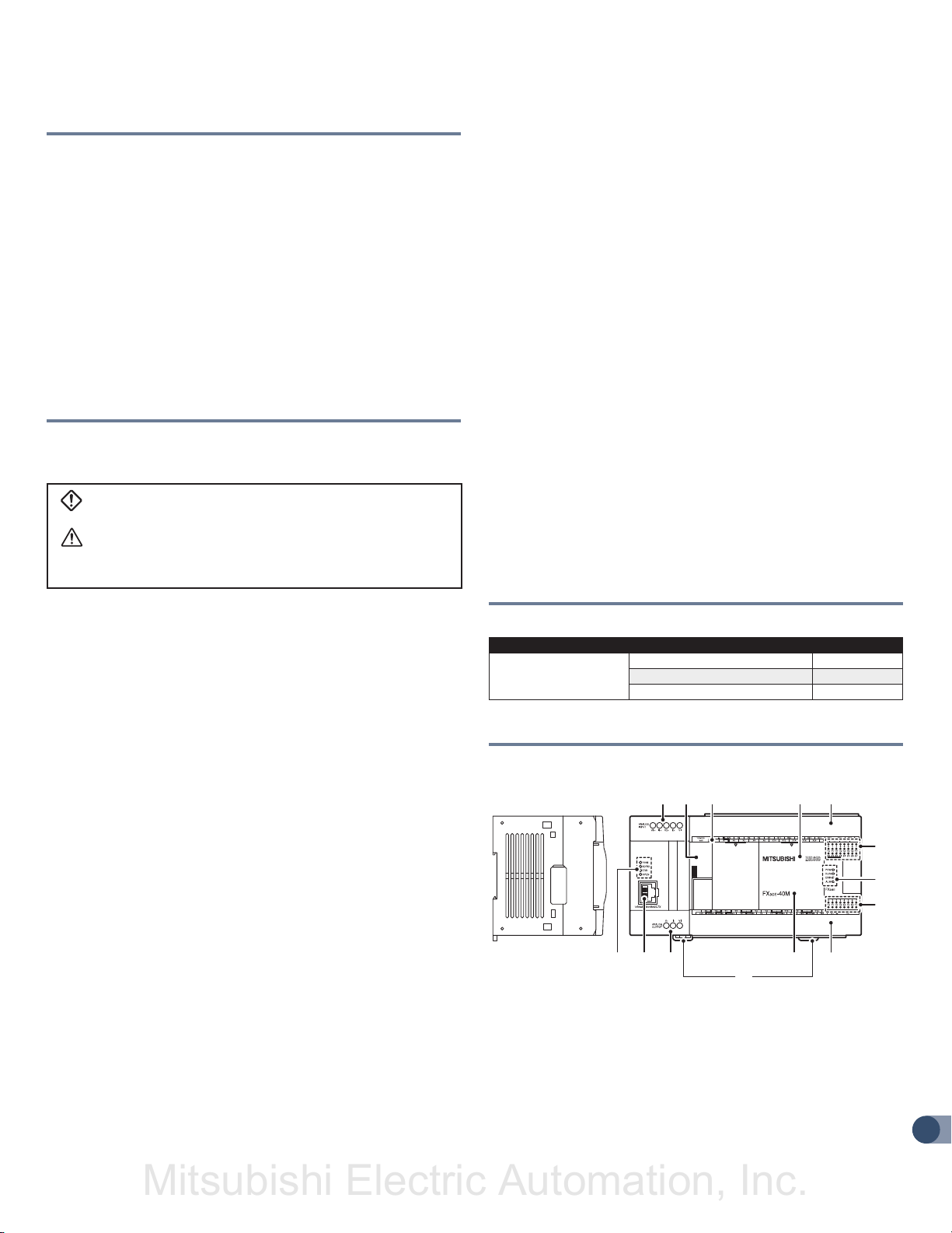
1.3 FRONT PANEL
n FACTORY DEFAULT CONFIGURATION (STANDARD)
]01[ ]1[
[2]
[3] [4]
[5]
[6]
[7]
[8]
[5][11][12][13]
[9]
[1] Peripheral device connector cover The peripheral device
connector, variable analog potentiometers and RUN/STOP switch are
located under this cover.
[2] Terminal names The signal names for power supply, input and
output terminals are shown.
[3] Top cover (S) (40 points, 60 points type only) Mount the expansion
board under this cover.
3
Page 4
FX3GE QUICK START MANUAL
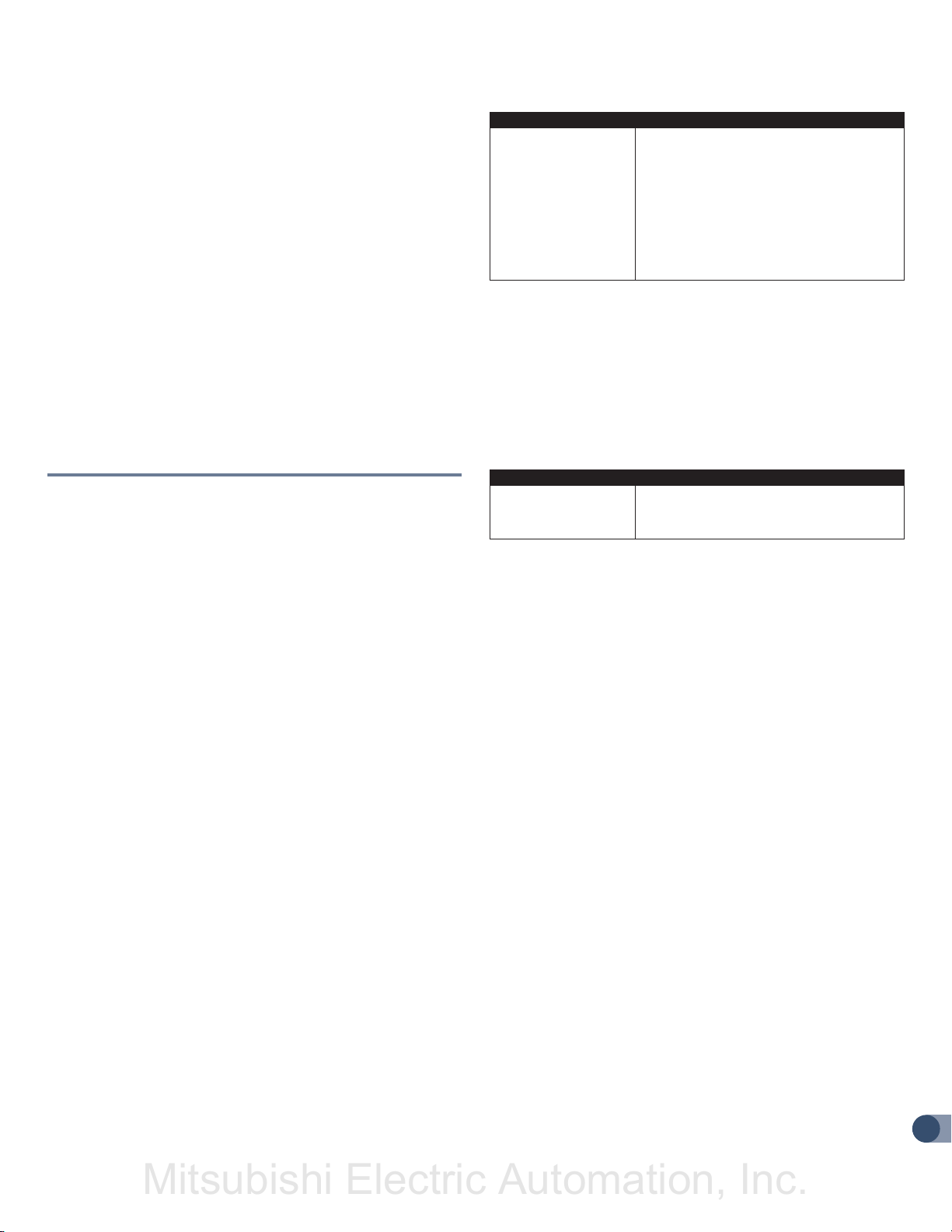
90 (3.55")
82 (3.23")
Mitsubishi Electric Automation, Inc.
[4] Terminal block covers The covers can be opened for wiring. Keep
the covers closed while the PLC is running (the unit power is on).
[5] Input display LEDs (red) When an input terminal (X000 or more)
is turned on, the corresponding LED lights.
[6] Operation status display LEDs The operation status of the PLC
can be checked with the LEDs. The LEDs turn off, light and flash
according to the following table. For details on the operation status,
refer to Section 10.
LED Name
POW Green On while power is on the PLC.
RUN Green On while the PLC is running.
ERR Red
ALM Red
Display
Color
Description
Flashing when a program error occurs.
Lights when a CPU error occurs.
Lights when the battery voltage drops.
(When the optional battery is used)
[7] Output display LEDs (red) When an output terminal (Y000 or
more) is turned on, the corresponding LED lights.
[8] Model name (abbreviation) The model name of the main unit is
indicated. Check the nameplate on the right side for the model name.
[9] DIN rail mounting hooks The main unit can be installed on
DIN46277 rail (35mm (1.38") wide).
[10] Analog input terminal block
[11] Analog output terminal block
[12] 10BASE-T/100BASE-TX connector (RJ45)
[13] Ethernet status LEDs
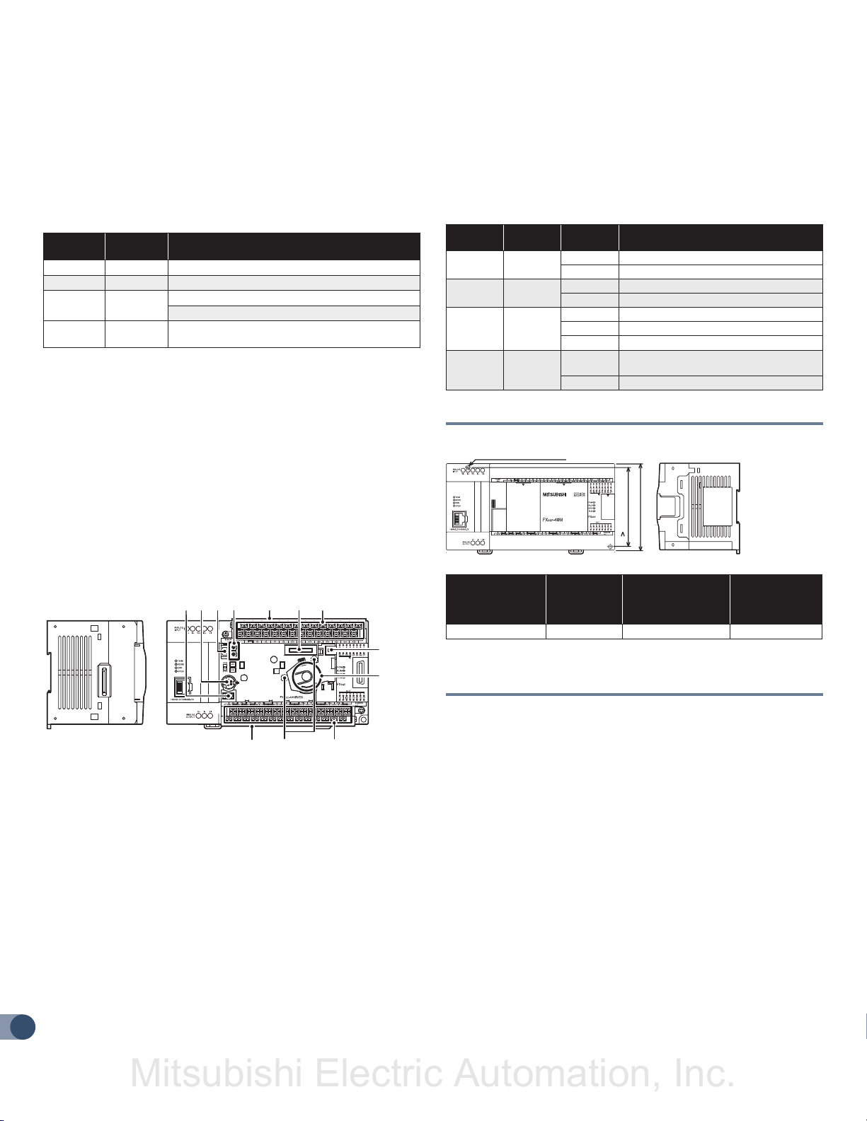
[9] Battery holder This holder accommodates the optional battery.
[10] Power supply terminal, Output (Y) terminals Wire loads
(contactors, solenoid valves, etc.) to be driven to the terminals.
[11] Optional equipment connecting screw holes These holes are
designed to secure the expansion board and memory cassette with
screws.
n LED STATUS
LED
Display
POW Green
RUN Green
ERR Red
ALM Red
LED
Color
Status Description
ON Power is on
OFF Power is off
ON Running
OFF Stopped
ON When a CPU error occurs
Flicker When a program error occurs
OFF When a normal status
ON
OFF When the battery voltage normal status
When the battery voltage drops
(When the optional battery is installed)
2. DIMENSIONS
2-ø4.5 mounting holes
Unit: mm (inches)
n WITH TERMINAL COVER OPEN
[1] Peripheral device connector (USB) Connect a programming tool
[2] [3] [4] [5][5] [6] [7]
[1]
[5]
[10][11]
(PC) to program a sequence.
[2] Peripheral device connector (RS-422) Connect a programming
tool to program a sequence.
[3] RUN/STOP switch To stop writing (batch) of the sequence program
or operation, set the switch to STOP (slide it downward). To start
operation (run the machine), set it to RUN (slide it upward).
[4] Variable analog potentiometers Upper side: VR1,
Lower side: VR2 Two variable analog potentiometers are built in. Upper
side : VR1, Lower side : VR2
[5] Terminal cover A protective terminal cover
[6] Optional equipment connector Connect the expansion board to
the connector.
[7] Power supply terminal, Input (X) terminals Wire switches and
sensors to the terminals.
[8] Battery connector Connect the optional battery to the connector.
4
[8]
[9]
Model Number
FX3GE-24MR/ES 130 (5.12") 105 (4.13") 0.60 (1.32 lbs)
W:
mm (inches)
W1:
mm (inches)
Direct Mounting
Hole Pitches
Weight:
kg (lbs)
Installation: 35mm wide DIN rail or Direct (screw) mounting (M4)
3. INSTALLATION
CAUTION INSTALLATION PRECAUTIONS
• Use the product within the generic environment specifications
described in this manual. Never use the product in areas with
excessive dust, oily smoke, conductive dusts, corrosive gas (salt
air, Cl2, H2S, SO2 or NO2), flammable gas, vibration or impacts, or
exposed to high temperature, condensation, or rain and wind. If the
product is used in such conditions, electric shock, fire, malfunctions,
deterioration or damage may occur.
• Do not touch the conductive parts of the product directly to avoid
failure or malfunctions.
• Install the product securely using a DIN rail or mounting screws.
• Install the product on a flat surface. If the mounting surface is
rough, undue force will be applied to the PC board, thereby causing
nonconformities.
• When drilling screw holes or wiring, make sure cutting or wire debris
does not enter the ventilation slits. Failure to do so may cause fire,
equipment failures or malfunctions.
• Be sure to remove the dust proof sheet from the PLC’s ventilation
port when installation work is completed. Failure to do so may cause
fire, equipment failures or malfunctions.
Page 5
FX3GE QUICK START MANUAL
Mitsubishi Electric Automation, Inc.
• Connect the extension cables, peripheral device cables, input/output
cables and battery connecting cable securely to their designated
connectors. Unsecured connection may cause malfunctions.
• Turn off the power before attaching or detaching the following
devices. Failure to do so may cause device failures or malfunctions.
Peripheral devices, display modules and battery.
• When a dust proof sheet is supplied with units, keep the sheet
applied to the ventilation slits during installation and wiring work.
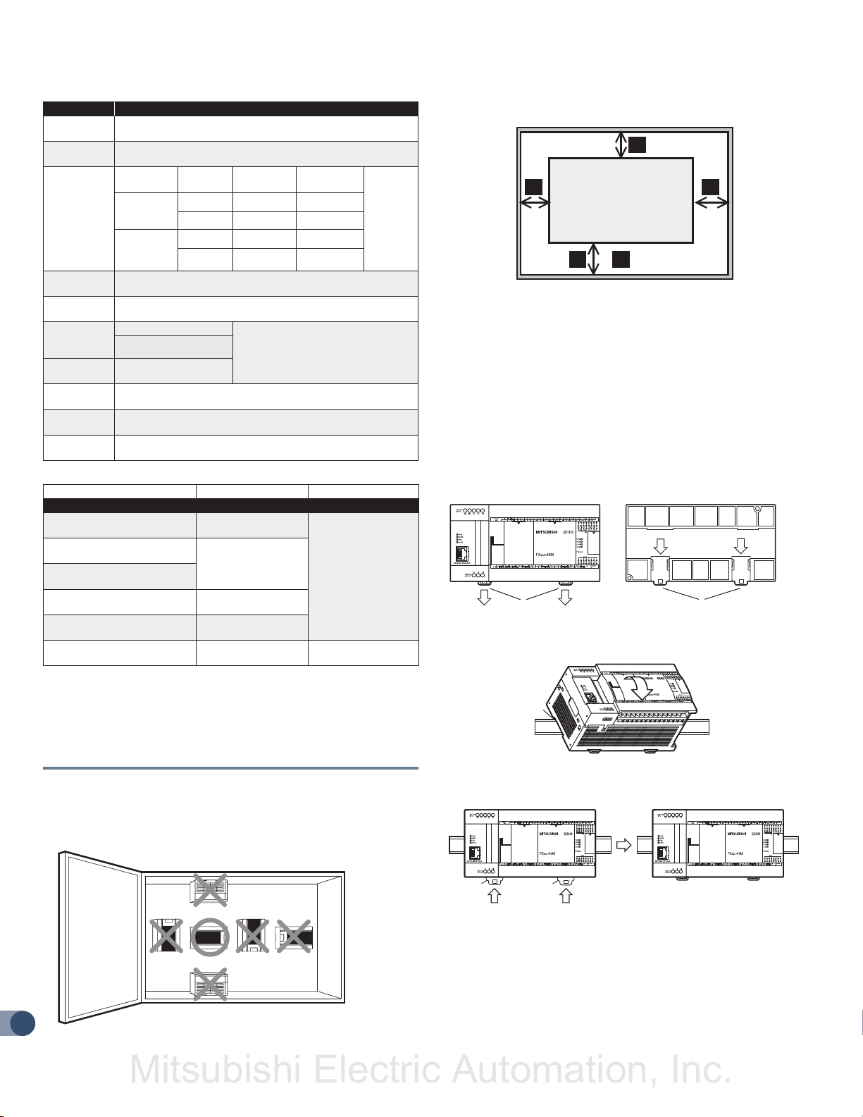
• To prevent temperature rise, do not install the PLC on a floor, a
ceiling or a vertical surface. Install it horizontally on a wall.
• Keep a space of 50mm (1.97") or more between the unit main body
and another device or structure (part A). Install the unit as far away
as possible from highvoltage lines, high-voltage devices and power
equipment.
DANGER WIRING PRECAUTIONS
• Make sure to cut off all phases of the power supply externally before
attempting installation or wiring work. Failure to do so may cause
electric shock or damage to the product.
3.1 SPECIFICATIONS
n COMPLIANCE WITH EC DIRECTIVE (CE MARKING )
This document does not guarantee that a mechanical system including
this product will comply with the following standards. Compliance
to EMC directive and LVD directive of the entire mechanical system
should be checked by the user / manufacturer.
n REQUIREMENT FOR COMPLIANCE WITH EMC DIRECTIVE
The following products have shown compliance through direct testing
(of the identified standards below) and design analysis (through the
creation of a technical construction file) to the European Directive for
Electromagnetic Compatibility (2004/108/EC) when used as directed
by the appropriate documentation.
ATTENTION
• This product is designed for use in industrial applications.
• Manufactured by:
Mitsubishi Electric Corporation
2-7-3 Marunouchi, Chiyoda-ku, Tokyo, 100-8310 Japan
• Manufactured at:
Mitsubishi Electric Corporation Himeji Works
840 Chiyoda-machi, Himeji, Hyogo, 670-8677 Japan
• Authorized Representative in the European Community:
Mitsubishi Electric Europe B.V.
Gothaer Str. 8, 40880 Ratingen, Germany
Type: Programmable Controller (Open Type Equipment)
Models: MELSEC FX3GE series, FX3G series, FX3U series
Manufactured:
from November 1st, 2008
FX3G-232-BD
FX3G-422-BD
FX3G-5DM
from March 1st, 2013
FX3GE-24MR/ES
from September 1st, 2013
FX3G-485-BD-RJ
Standard REMARK
Compliance with all relevant aspects of the standard.
EMI
• Radiated Emissions
EN61131-2:2007
Programmable controllers
- Equipment
requirements and tests
• Conducted Emissions
EMS
• Radiated electromagnetic field
• Fast transient burst
• Electrostatic discharge
• High-energy surge
• Voltage drops and interruptions
• Conducted RF
• Power frequency magnetic field
n REQUIREMENT FOR COMPLIANCE WITH LVD DIRECTIVE
The following products have shown compliance through direct testing
(of the identified standards below) and design analysis (through the
creation of a technical construction file) to the European Directive for
Low Voltage (2006/95/EC) when used as directed by the appropriate
documentation.
Type: Programmable Controller (Open Type Equipment)
Models: MELSEC FX3GE series
Manufactured: from March 1st, 2013 FX3GE-24MR/ES
Standard REMARK
EN61131-2:2007
Programmable controllers
- Equipment requirements
and tests
The equipment has been assessed as a component
for fitting in a suitable enclosure which meets the
requirements of EN61131-2:2007
n CAUTION FOR COMPLIANCE WITH EC DIRECTIVE
Installation in Enclosure
Programmable logic controllers are open-type devices that must
be installed and used within conductive control boxes. Please use
the FX3GE Series programmable logic controllers while installed in
conductive shielded control boxes. Please secure the control box lid to
the control box (for conduction). Installation within a control box greatly
affects the safety of the system and aids in shielding noise from the
programmable logic controller.
Analog input/output
The analog input/output have been found to be compliant to the
European standards in the aforesaid manual and directive. However,
for the very best performance from what are in fact delicate measuring
and controlled output devices, Mitsubishi Electric would like to make
the following points.
As analog devices are sensitive by nature, their use should be
considered carefully. For users of proprietary cables (integral with
sensors or actuators), these users should follow those manufacturers’
installation requirements. Mitsubishi Electric recommends that shielded
cables be used. If NO other EMC protection is provided, users may
experience temporary loss or accuracy between +10% / -10% in very
heavy industrial areas. However, Mitsubishi Electric suggests that
adequate EMC precautions be followed for the users complete control
system.
Sensitive analog cables should not be laid in the same trunking
or cable conduit as high voltage cabling. Where possible, users
should run analog cables separately.
Good cable shielding should be used. When terminating the shield
at Earth, ensure that no earth loops are accidentally created.
When reading analog values, EMC accuracy can be improved
by averaging the readings. This can be achieved either through
functions on the analog products or through a user’s program in
the FX3GE Series PLC main unit.
5
Page 6
FX3GE QUICK START MANUAL
B
Mitsubishi Electric Automation, Inc.
Item Specification
Ambient
Temperature
Ambient
Humidity
Vibration
Resistance *1
Shock
Resistance *1
Noise
Resistance
Dielectric
Withstand
Voltage *2
Insulation
Resistance *2
Grounding
Working
Atmosphere
Working
Altitude
Terminal Dielectric Strength Insulation Resistance
Main units
Between power supply terminal
(AC power) and ground terminal
Between power supply terminal
(DC power) and ground terminal
Between input terminal (24VDC)
and ground terminal
Between output terminal (relay)
and ground terminal
10BASE-T/100BASE-TX
connector and ground terminal
Main unit analog terminal and
ground terminal
1. The criterion is shown in IEC61131-2.
2. Dielectric withstand voltage and insulation resistance are shown above.
3. For common grounding, refer to Section 4.2.
4. The PLC cannot be used at a pressure higher than the atmospheric pressure to
avoid damage.
0 to 55°C (32 to 131°F) when operating and
-25 to 75°C (-13 to 167°F) when stored
5 to 95%RH (no condensation) when operating
Frequency
(Hz)
When
installed on
DIN rail
When
installed
directly
147m/s² Acceleration, Action time: 11ms, 3 times by half-sine pulse
in each direction X, Y, and Z
By noise simulator at noise voltage of 1,000Vp-p, noise width of
1μs, rise time of 1ns and period of 30 to 100Hz
1.5kVAC for one minute
500VAC for one minute
5MΩ or more by 500VDC
megger
Class D grounding (grounding resistance: 100Ω or less) <Common
grounding with a heavy electrical system is not allowed.> *3
Free from corrosive or flammable gas and excessive conductive
dusts
<2000m *4
10 to 57 - 0.035
57 to 150 4.9 -
10 to 57 - 0.075
57 to 150 9.8 -
Acceleration
(m/s²)
Between each terminals *2 and ground
terminal
1.5 kVAC for one minute
500VAC for one minute
1.5 kVAC for one minute
500VAC for one minute
Not allowed Not allowed
Half amplitude (mm)
5MΩ or more by
500VDC megger
Sweep
Count for
X, Y, Z:
10 times
(80 min
in each
direction)
Space enclosure
A
A A
FX3G Series
main unit
≥ 50mm (1.97")
A
n AFFIXING THE DUST PROOF SHEET
The dust proof sheet should be affixed to the ventilation port before
beginning the installation and wiring work. For the affixing procedure,
refer to the instructions on the dust proof sheet. Be sure to
remove the dust proof sheet when the installation and wiring work is
completed.
n PROCEDURES FOR INSTALLING TO AND DETACHING
FROM DIN RAIL
The products can be installed on a DIN46277 rail [35mm (1.38") wide].
1) Push out all DIN rail mounting hooks (below fig. A).
1) 1)
2) Fit the upper edge of the DIN rail mounting groove (below fig. B)
onto the DIN rail.
A
A
1)
A
1)
3.2 MOUNTING INSTRUCTIONS
3) Lock the DIN rail mounting hooks (below fig. C) while pressing the
n INSTALLATION LOCATION
PLC against the DIN rail.
Install the PLC in an environment conforming to the generic
specifications, installation precautions and notes.
Installation location in enclosure
C
C
3) 3)
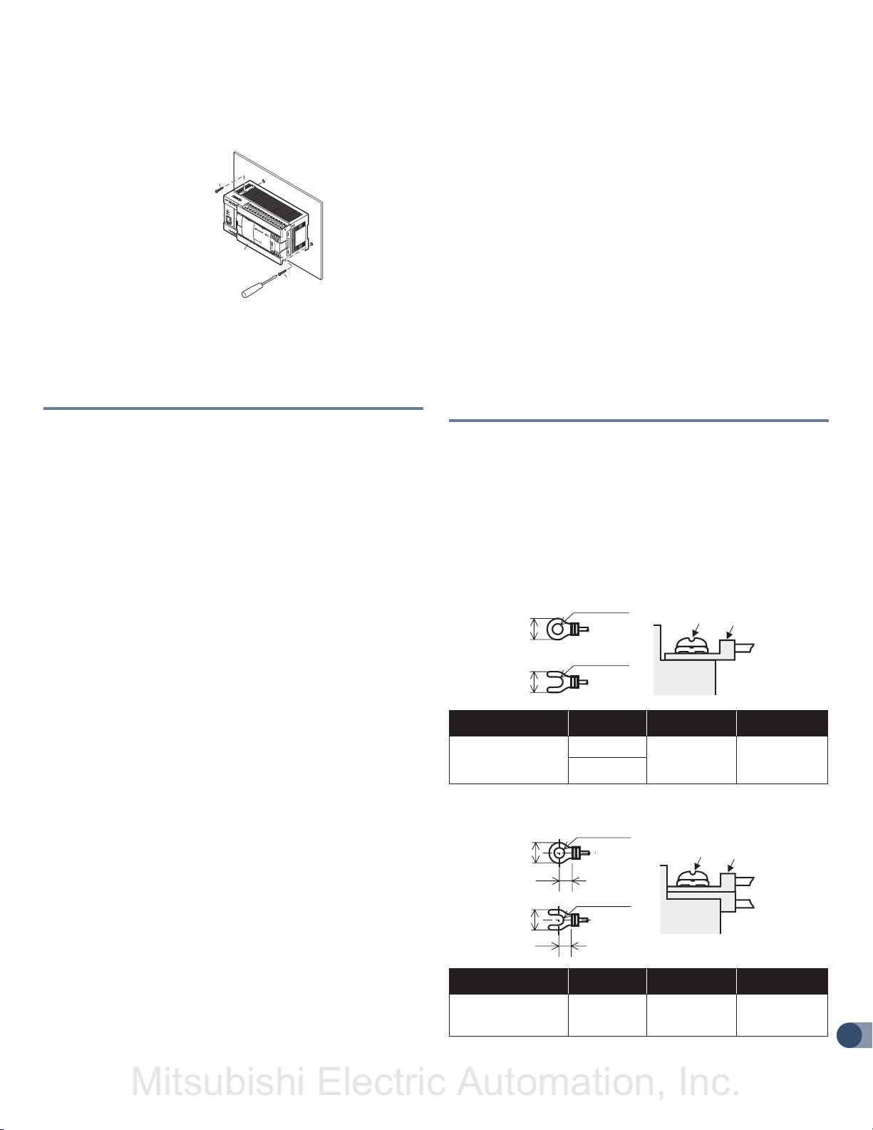
n PROCEDURES FOR MOUNTING WITH M4 SCREWS
MOUNTING HOLE PITCHES
Refer to the External Dimensions (Section 2) for the product’s
mounting hole pitch information
6
Page 7
FX3GE QUICK START MANUAL
Mitsubishi Electric Automation, Inc.
n INSTALLATION
1) Make mounting holes in the mounting surface referring to the
external dimensions diagram.
B
A
B
2) Fit the main unit (A in the above figure) based on the holes, and
secure it with M4 screws (B in the above figure). The mounting hole
pitches and number of screws depend on the product. Refer to the
external dimensions diagram.
4. SPECIFICATIONS AND WIRING
DANGER DESIGN PRECAUTIONS
• Make sure to have the following safety circuits outside of the PLC
to ensure safe system operation even during external power supply
problems or PLC failure. Otherwise, malfunctions may cause serious
accidents.
Most importantly, have the following: an emergency stop circuit,
a protection circuit, an interlock circuit for opposite movements
(such as normal vs. reverse rotation), and an interlock circuit
(to prevent damage to the equipment at the upper and lower
positioning limits).
Note that when the PLC CPU detects an error, such as a
watchdog timer error, during self-diagnosis, all outputs are turned
off. Also, when an error that cannot be detected by the PLC CPU
occurs in an input/output control block, output control may be
disabled. External circuits and mechanisms should be designed to
ensure safe machinery operation in such a case.
Note that when an error occurs in a relay the output could be
held either on or off. For output signals that may lead to serious
accidents, external circuits and mechanisms should be designed
to ensure safe machinery operation in such a case.
• Do not bundle the control line together with or lay it close to the
main circuit or power line. As a guideline, lay the control line at least
100mm (3.94") or more away from the main circuit or power line.
Noise may cause malfunctions.
• Install module so that excessive force will not be applied to the builtin programming connectors, power connectors or I/O connectors.
Failure to do so may result in wire damage/breakage or PLC failure.
• Even if the AC power supply causes an instantaneous power failure
for less than 10 ms, the PLC can continue to operate.
• If a long-time power failure or an abnormal voltage drop occurs,
the PLC stops, and output is turned off. When the power supply is
restored, it will automatically restart (when the RUN input is on).
CAUTION WIRING PRECAUTIONS
• Connect the AC power supply to the dedicated terminals specified in
this manual. If an AC power supply is connected to a DC input/output
terminal or DC power supply terminal, the PLC will burn out.
• Do not wire vacant terminals externally. Doing so may damage the
product.
• Use class D grounding (grounding resistance of 100Ω or less) with
a wire of 2mm² or thicker on the grounding terminal of the FX3GE
Series main unit. However, do not connect the ground terminal at the
same point as a heavy electrical system.
• When drilling screw holes or wiring, make sure cutting or wire debris
does not enter the ventilation slits. Failure to do so may cause fire,
equipment failures or malfunctions.
• Make sure to properly wire to the terminal in accordance with the
following precautions. Failure to do so may cause electric shock,
equipment failures, a short-circuit, wire breakage, malfunctions, or
damage to the product.
The disposal size of the cable end should follow the dimensions
described in the manual.
Tightening torque should follow the specifications in the manual.
• Input/output wiring 50 to 100m (164'1" to 328'1") long will cause
almost no problems of noise, but, generally, the wiring length should
be less than 20m (65'7") to ensure the safety.
4.1 WIRING
n CABLE END TREATMENT AND TIGHTENING TORQUE
• For the terminals of FX3GE series PLC, M3 screws are used.
The electric wire ends should be treated as shown below.
• Tighten the screws to a torque of 0.5 to 0.8 N•m.
• Do not tighten terminal screws with a torque exceeding the
regulation torque.
• Failure to do so may cause equipment failures or malfunctions.
n WHEN ONE WIRE IS CONNECTED TO ONE TERMINAL
φ3.2 (0.13")
6.2 mm (0.24")
or less
φ3.2 (0.13")
6.2 mm (0.24")
or less
Terminal Manufacturer Type No. Certification
JAPAN SOLDERLESS
TERMINAL MFG CO
LTD (JST)
FV1.25-B3A
FV2-MS3
Terminal
screw
Terminal
UL Listed YA-1(JST)
Solderless
terminal
Pressure
Bonding Tool
n WHEN TWO WIRES ARE CONNECTED TO ONE TERMINAL
6.2 mm (0.24")
or less
6.2 mm (0.24")
or less
Terminal Manufacturer Type No. Certification
JAPAN SOLDERLESS
TERMINAL MFG CO
LTD (JST)
φ3.2 (0.13")
6.3 mm(0.25")
or more
φ3.2 (0.13")
6.3 mm(0.25")
or more
FV1.25-B3A UL Listed YA-1(JST)
Terminal
screw
Terminal
Solderless
terminal
Pressure
Bonding Tool
7
Page 8
FX3GE QUICK START MANUAL
Mitsubishi Electric Automation, Inc.
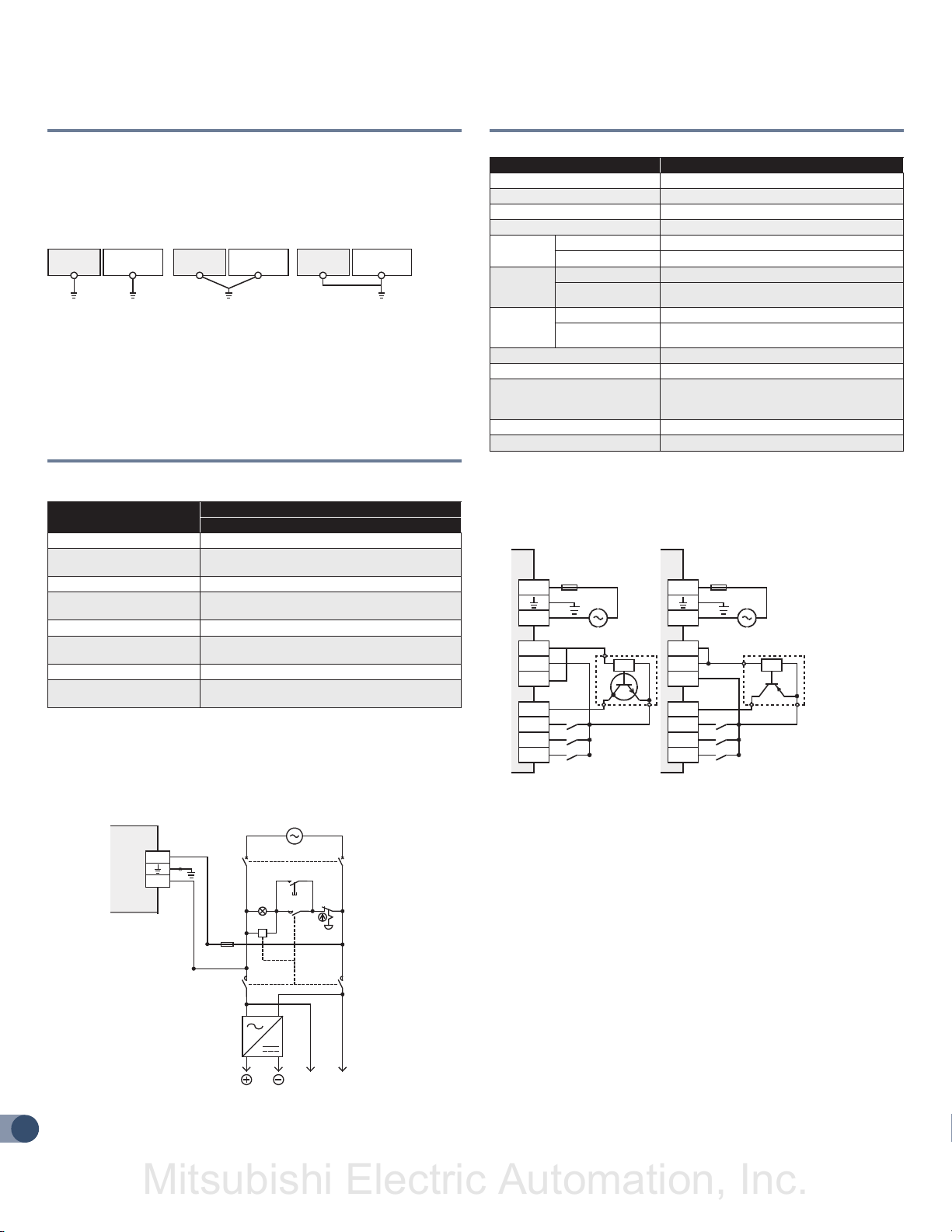
4.2 GROUNDING
Ground the PLC as stated below.
• Perform class D grounding. (Grounding resistance: 100Ω or less)
• Ground the PLC independently if possible.
If it cannot be grounded independently, ground it jointly as shown
below.
Other
equipment
Independent grounding
(Best condition)
Shared grounding
(Good condition)
Other
equipment
PLCPLCPLC
Common grounding
Other
equipment
(Not allowed)
• Use ground wires thicker than AWG14 (2 mm²).
• Position the grounding point as close to the PLC as possible to
decrease the length of the ground wire.
4.3 POWER SUPPLY SPECIFICATIONS AND
WIRING DIAGRAM
n POWER SUPPLY SPECIFICATIONS FX3GE-24MR/ES
Item
Supply Voltage 100 to 240VAC
Allowable Supply Voltage
Range
Rated Frequency 50/60Hz
Allowable Instantaneous
Power Failure Time
Power Fuse 250V 1A
Rush Current
Power Consumption *1 32W
24VDC Service Power
Supply
*1 This item shows values when all 24VDC service power supplies are used in the
maximum configuration connectable to the main unit.
Specification
AC Power Type
85 to 264VAC
Operation can be continued upon occurrence of
instantaneous power failure for 10 ms or less.
30A max. 5ms or less/100 VAC 50A max. 5ms or
less/200 VAC
400mA
n EXAMPLE OF EXTERNAL WIRING (AC POWER TYPE)
100 to 240VAC power is supplied to the main unit and input/output
extension unit.
PLC
Main unit
L
(*)
N
*Class D grounding
8
Fuse
100 to 240V AC
Breaker
Power on
Emer-
MC
DC
power
supply
gency
MCMC
PL
MC
DC AC
Power supply for loads connected
to PLC output terminals
4.4 INPUT SPECIFICATIONS AND WIRING DIAGRAM
n 24VDC INPUT [TYPE
Item FX3GE-24MR/ES
Number of Input Points 14 points (16 points) *1
Input Connecting Type Terminal block (M3 screw)
Input Form Sink/Source
Input Signal Voltage AC power supply type: 24V DC +10%, -10%
Input
Impedance
Input
Signal
Current
ON Input
Sensitivity
Current
OFF Input Sensitivity Current 1.5mA or less
Input Response Time Approx. 10ms
Input Signal Form
Input Circuit Insulation Photocoupler insulation
Input Operation Display LED on panel lights when photocoupler is driven
*1 Each value inside ( ) indicates the number of occupied points.
X000 to X007 3.3kΩ
X010 or More 4.3kΩ
X000 to X007 7mA/24VDC
X010 or More 5mA/24VDC
X000 to X007 4.5mA or more
X010 or More 3.5mA or more
No-voltage contact input
Sink input: NPN open collector transistor
Source input: PNP open collector transistor
EXAMPLES OF INPUT WIRING (AC POWER TYPE)
1. Each value inside ( ) indicates the number of occupied points.
1. Sink input 2. Source input
]1[]1[
Fuse
L
N
S/S
0V
24V
X000
X001
X002
X003
(
) Class D grounding
*
(
*
100 to 240V AC
3-wire type
sensor
L
N
S/S
0V
24V
X000
X001
X002
X003
Fuse
()
)
*
100 to 240V AC
3-wire type
sensor
n INSTRUCTIONS FOR CONNECTING INPUT DEVICES
In the case of no-voltage contact The input current of this PLC is
5 to 7mA/24VDC. Use input devices applicable to this current. If
no-voltage contacts (switches) for large current are used, contact
failure may occur.
In the case of input device with built-in series diode The voltage
drop of the series diode should be approx. 4V or less. When lead
switches with a series LED are used, up to two switches can be
connected in series. Also make sure that the input current is over the
input-sensing level while the switches are ON.
In the case of input device with built-in parallel resistance Use a
device with a parallel resistance of 15kΩ or more. When the resistance
is less than 15kΩ, connect a bleeder resistance.
In the case of 2-wire proximity switch Use a two-wire proximity
switch whose leakage current is 1.5mA or less when the switch is off.
When the current is 1.5mA or more, connect a bleeder resistance.
Page 9
FX3GE QUICK START MANUAL
Mitsubishi Electric Automation, Inc.
4.5 PULSE CATCH (M8170 TO M8175)
The PLC (main unit) is provided with a pulse catch function and has 6
pulse catch input points.
For details on programming, refer to the HELP section in GX Works2.
n CAUTIONS FOR PULSE CATCH
1. Non-overlap of input numbers
The input terminals X000 to X005 can be used for high-speed
counter, input interruption, pulse catch, speed detection (SPD)
instructions and general-purpose input.
Take care not to overlap the input numbers.
2. Cautions in wiring
It is recommended to use shielded twisted-pair cables for connection
cables.
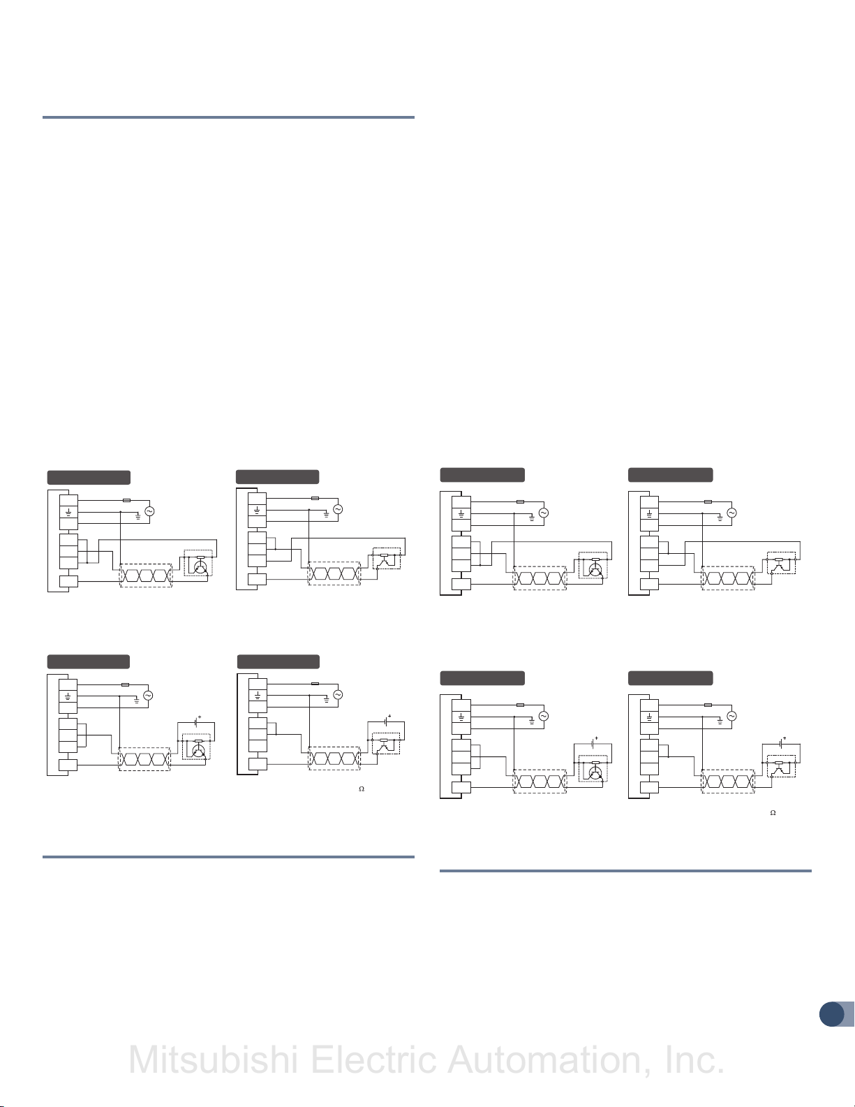
n EXAMPLES OF EXTERNAL WIRING
It is recommended to use shielded twisted-pair cables for connection
cables. Ground the shield of each shielded cable only on the PLC side.
n EXAMPLES OF PULSE CATCH (M8170) WIRING USING X000
When another input terminal is used, wire it according to the following
diagrams.
1) When 24VDC service power supply is used
Sink wiring
L
Class D grounding *
N
S/S
0V
24V
X000
Fuse
Three-wire
Source wiring
L
N
S/S
0V
24V
X000
* The grounding resistance should be 100Ω or less.
Fuse
Class D grounding *
Three-
wire
(SPD) instructions and general-purpose input. Take care not to
overlap the input numbers. However, overlap of input numbers is
allowed for input interruptions.
2. When the pulse width/period measurement function and high-speed
counters are used together, the overall frequency of high-speed
counters is affected.
3. Make sure that the total frequency of four input channels is 50
kHz or less when using the pulse width/period measurement
function. For details on programming, refer to the HELP section in
GX Works2.
4. Cautions in wiring
It is recommended to use shielded twisted-pair cables for connection
cables.
n EXAMPLES OF EXTERNAL WIRING
It is recommended to use shielded twisted-pair cables for connection
cables. Ground the shield of each shielded cable only on the PLC side.
n EXAMPLES OF PULSE WIDTH MEASUREMENT WIRING
USING X000
When another input terminal is used, wire it according to the following
diagrams.
1) When 24VDC service power supply is used
Sink wiring
L
N
S/S
0V
24V
X000
Fuse
Class D grounding *
Three-wire
Source wiring
L
N
S/S
0V
24V
X000
* The grounding resistance should be 100Ω or less.
Fuse
Class D grounding *
Three-
wire
2) When 24VDC external power supply is used
Sink wiring
L
N
S/S
0V
24V
X000
Fuse
* gnidnuorg D ssalC
24V DC
Three-wire
Source wiring
L
N
S/S
0V
24V
X000
* The grounding resistance should be 100 or less.
Fuse
* gnidnuorg D ssalC
24V DC
Three-
wire
4.6 PULSE WIDTH/PULSE PERIOD MEASUREMENT SPECIFICATIONS AND WIRING
Four input points in the PLC (main unit) can be used for the pulse
width/period measurement function which enables measurement of the
pulse width or pulse frequency in units of 10 s.
For details on programming, refer to the HELP section in GX Works2.
n CAUTIONS FOR PULSE WIDTH/PERIOD
MEASUREMENT FUNCTION
1. Non-overlap of input numbers
The input terminals X000, X001, X003 and X004 can be used for
high-speed counter, input interruption, pulse catch, speed detection
2) When 24VDC external power supply is used
Sink wiring
L
N
S/S
0V
24V
X000
Fuse
24V DC
Three-wire
Source wiring
L
N
S/S
0V
24V
X000
* The grounding resistance should be 100 or less.
Fuse
* gnidnuorg D ssalC* gnidnuorg D ssalC
24V DC
Three-
wire
4.7 HIGH SPEED COUNTERS SPECIFICATIONS AND WIRING
High-speed counters use input terminals X000 to X007 of the main unit
for inputs, and offer counting up to 60kHz (1 phase).
Input terminals not used for high-speed counters are available for
general-purpose inputs.
For details on programming, refer to the HELP section of GX Works2.
n EXAMPLES OF EXTERNAL WIRING (ROTARY ENCODER)
1-phase 1-input [C235 to C245]
The following examples of wiring apply to the cases where C235 is
9
Page 10

FX3GE QUICK START MANUAL
Mitsubishi Electric Automation, Inc.
used. When another high-speed counter number is used, wire the
counter referring to the following diagrams. It is recommended to use
shielded twisted-pair cables for connection cables. Ground the shield
of each shielded cable only on the PLC side.
1) NPN open collector transistor output rotary encoder
In the case of sink wiring
L
N
S/S
0V
24V
X000
PLC
* The grounding resistance should be 100Ω or less.
Fuse
Class D
grounding*
24V DC
Rotary encoder
24V
0V
Phase A
Phase B
Phase Z
2) PNP open collector transistor output rotary encoder
In the case of source wiring
L
N
S/S
0V
24V
X000
PLC
* The grounding resistance should be 100Ω or less.
Fuse
Class D
grounding*
24V DC
Rotary encoder
24V
0V
Phase A
Phase B
Phase Z
2) PNP open collector transistor output rotary encoder
In the case of source wiring
L
N
S/S
0V
24V
X000
PLC
* The grounding resistance should be 100Ω or less.
X001
Fuse
Class D
grounding*
24V DC
Rotary encoder
24V
0V
Phase A
Phase B
Phase Z
4.8 OUTPUT SPECIFICATIONS AND WIRING
Item FX3GE-24MR/ES
Number of Output Points 10 points (16 points) *1
Input Connecting Type Terminal block (M3 screw)
Output Form Relay
External Power Supply
Max. Load
Minimum Load 5VDC, 2mA (reference value)
Open Circuit Leakage Current -
Response
Time
Circuit Insulation Mechanical insulation
Display of Output Operation LED lights when power is applied to relay coil
1. Each value inside ( ) indicates the number of occupied points.
2. Between 250V and 240V CE, UL, and cUL are not compliant.
3. The total load current of resistance loads per common terminal should be the
following value or less.
1 output point/common terminal: 2A
4 output points/common terminal: 8A
Resistance Load 2A/point *3
Inductive Load 80VA
OFF–ON
ON–OFF
30VDC or less
240VAC or less *2
Approx. 10ms
2-phase 2-input [C251 to C255]
The following examples of wiring apply to the cases where C251 is
used. When another high-speed counter number is used, wire the
counter referring to the following diagrams.
It is recommended to use shielded twisted-pair cables for connection
cables. Ground the shield of each shielded cable only on the PLC side.
1) NPN open collector transistor output rotary encoder
In the case of sink wiring
L
N
S/S
0V
24V
X000
PLC
* The grounding resistance should be 100Ω or less.
10
X001
Fuse
Class D
grounding*
24V DC
Rotary encoder
24V
0V
Phase A
Phase B
Phase Z
n LIFE OF RELAY OUTPUT CONTACT
The product life of relay contacts considerably varies depending on the
load type used. Take care that loads generating reverse electromotive
force or rush current may cause poor contact or deposition of contacts
which may lead to considerable reduction of the contact product life.
Inductive load Inductive loads generate large reverse electromotive
force between contacts at shutdown may cause arcing. At a fixed
current consumption, as the power factor (phase between current and
voltage) gets smaller, the arc energy gets larger. The standard life of
the contact used for Inductive loads, such as contactors and solenoid
valves, is 500 thousand operations at 20VA.
The following table shows the approximate life of the relay based on
the results of our operation life test.
Test condition: 1 sec. ON / 1 sec. OFF.
Load Capacity Contact Life
20VA
35VA
80VA
0.2A/100VAC
0.1A/200VAC
0.35A/100VAC
0.17A/200VAC
0.8A/100VAC
0.4A/200VAC
3 million times
1 million times
2 hundred thousand times
The product life of relay contacts becomes considerably shorter
than the above conditions when the rush overcurrent is shut down.
Some types of inductive loads generate rush current 5 to 15 times
Page 11

FX3GE QUICK START MANUAL
Mitsubishi Electric Automation, Inc.
the stationary current at activation. Make sure that the rush current
does not exceed the current corresponding to the maximum specified
resistance load.
Lamp load Lamp loads generally generate rush current 10 to 15 times
the stationary current. Make sure that the rush current does not exceed
the current corresponding to the maximum specified resistance load.
Capacitive load Capacitive loads can generate rush current 20 to 40
times the stationary current. Make sure that the rush current does not
exceed the current corresponding to the maximum specified resistance
load. Capacitive loads such as capacitors may be present in electronic
circuit loads including inverters.
EXAMPLE OF RELAY OUTPUT WIRING
Load
Load
Y000
COM0
Y001
COM1
PLC
Fuse
Fuse
DC power
supply
AC power
supply
n CAUTIONS IN EXTERNAL WIRING
Protection circuit for load short-circuiting
When a load connected to the output terminal short-circuits, the printed
circuit board may be burnt out. Fit a protective fuse on the output
circuit.
Protection circuit of contact when inductive load is used
An internal protection circuit for the relays is not provided for the
relay output circuit in this product. It is recommended to use inductive
loads with built-in protection circuits. When using loads without built-in
protection circuits, insert an external contact protection circuit, etc. to
reduce noise and extend the product life.
DC CIRCUIT Connect a diode in parallel with the load. Use a diode
(for commutation) having the following specifications:
Item Standard
Reverse Voltage 5 to 10 times the load voltage
Forward Current Load current or more
AC CIRCUIT Connect the surge absorber (combined CR components
such as a surge killer and spark killer, etc.) parallel to the load. Select
the rated voltage of the surge absorber suitable to the output used.
Refer to the table below for other specifications.
Item Standard
Electrostatic Capacity Approx. 0.1μF
Resistance Value Approx. 100 to 200Ω
5. BUILT-IN ETHERNET
5.1 ETHERNET SPECIFICATIONS AND WIRING
CAUTION: DESIGN PRECAUTIONS
• Observe the following items. Failure to do so may cause incorrect
datawriting through noise to the PLC and result in PLC failure,
machine damage or other accident.
Do not bundle the control line together with or lay it close to the
main circuit or power line. As a guideline, lay the control line at
least 100mm (3.94") or more away from the main circuit or power
line. Noise may cause malfunctions.
Ground the shield wire or shield of a shielded cable. Do not use
common grounding with heavy electrical systems.
n COMMUNICATION SPECIFICATIONS
Item Specification
Data transmission speed 100Mbps/10Mbps
Transmission
Specifications
n PERFORMANCE SPECIFICATIONS
Item Specification
Functions
n CONNECTING TO THE NETWORK
The following explains how to connect the built-in Ethernet to 10BASET/100BASE-TX networks. Pay close attention to safety and use the
built-in Ethernet properly.
Sufficient network knowledge and safety precautions are required
when installing 10BASE-T or 100BASE-TX networks. Consult a
specialist when connecting cable terminals or installing trunk line
cables, etc.
Use a connection cable conforming to the standards shown in this
manual.
n CAUTIONS REGARDING POWERING THE HUB, PLC AND
ETHERNET SIMULTANEOUSLY
On some hubs, for a fixed period of time immediately after powering
up, even if packets are sent from the Ethernet device, there are cases
when packets are not sent to the external device. In this case, create a
sequence program that waits a sufficient amount of time after powering
up before sending packets.
Communication method Full-duplex/Half-duplex
Transmission method Base band
Maximum segment length 100m (328'1")
MELSOFT connections
MELSOFT Direct Connection (Simple Connection)
Diagnostics function from MELSOFT
INTERLOCK Loads, such as contactors for normal and reverse
rotations, that must not be turned on simultaneously should have an
interlock in the PLC program and an external interlock.
COMMON MODE Use output contacts of the PLC in the common
mode.
11
Page 12

FX3GE QUICK START MANUAL
Mitsubishi Electric Automation, Inc.
n APPLICABLE CABLE AND CONNECTOR
Connector RJ45 type modular jack
Pin Configuration The pin sequence of the 10BASE-T/100BASE-TX
connection connector (RJ45 type modular jack) of the built-in Ethernet
is as follows:
8 1
Pin No. Signal Direction Contents
1 TD+ Out + side of sending data
2 TD- Out - side of sending data
3 RD+ In + side of receiving data
4 Not used 5 Not used 6 RD- In - side of receiving data
7 Not used 8 Not used -
Applicable cable
10BASE-T
100BASE-TX
Cable conforming to Ethernet standard practice:
Category 3 or higher (STP cable)
Cable conforming to Ethernet standard practice:
Category 5 or higher (STP cable)
A straight cable is used. A cross cable can also be used when using
direct connection (simple connection) between the personal computer
and the FX3GE Series PLC.
n CONNECTING TO THE 10BASE-T/100BASE-TX NETWORK
This section explains how to connect the built-in Ethernet to the
10BASE-T, 100BASETX network.
The following shows the connection diagram for the twisted paid cable.
RJ45 type modular
Shielded twisted pair cable
(Category 3, 5 or higher)
RJ45 type modular jack
n OPERATING PROCEDURE
1. Connect the twisted pair cable to the hub.
2. Connect the twisted pair cable to the built-in Ethernet.
The built-in Ethernet detects whether it is 10BASE-T or
100BASE-TX, and in fullduplex or half-duplex transmission mode
automatically according to the hub. (Auto detection function) For
connection to a hub without the auto detection function, set the
half-duplex mode on the hub side.
5.2 PARAMETER SETTINGS AND DIAGNOSTICS
IN GX WORKS2
This section explains operations of GX Works 2 related to the Ethernet
adapter setting.
n ETHERNET PORT SETTING
Set Ethernet adapter on the “Ethernet Port” tab of the “FX Parameter”
screen in PLC parameters.
Setting Description
Select whether or not the Ethernet adapter is connected. When it is connected, specify the channel
Channel
Input Format
IP Address *1
Subnet Mask Pattern *1
Default Router IP Address
*1
Communication Data
Code
Disable Direct Connection
to MELSOFT
Do Not Respond to Search
for CPU on Network
Log Record Setting
*1 Set the IP address, subnet mask pattern and default router IP address upon
consulting a network administrator.
connected to the Ethernet adapter.
[Setting]
• Not Set
• CH1
• CH2
Select the input format and display format used to
set the IP address, subnet mask pattern and default
router IP address.
[Setting]
• Decimal
• Hexadecimal
Set the Ethernet adapter IP address.
[Setting range]
• 0.0.0.1 to 223.255.255.254 (Decimal)
• 00.00.00.01 to DF.FF.FF.FE (Hexadecimal)
Specify the subnet mask pattern.
[Setting range]
• 192.0.0.0 to 255.255.255.252 (Decimal)
• C0.00.00.00 to FF.FF.FF.FC (Hexadecimal)
Specify the IP address of the default router when it
is used.
[Setting range]
• 0.0.0.1 to 223.255.255.254 (Decimal)
• 00.00.00.01 to DF.FF.FF.FE (Hexadecimal)
Select the data code used for communication using
the MC protocol
• Binary Code
Communicates by binary code
• ASCII Code
Communicates by ASCII code
Set whether or not direct connection to MELSOFT is
disabled.
MELSOFT connection to the search for connection
CPU is disabled
A click of the button will display “Ethernet Port Log
Record Setting” screen
12
Page 13

FX3GE QUICK START MANUAL
HUB
Mitsubishi Electric Automation, Inc.
n LOG RECORD SETTING
On the “Log Record Setting” screen, set the error log save destination
and others. The user device (D, R) is used to save the error log, etc.
Click the [Log Record Setting] button on the “Ethernet Port” screen to
display the screen below.
Setting Description
Set Error Log Save Destination Error log is stored if checked
Number of Records
Head Device
Error
Log
Set access Log Save Destination Access log is stored if checked
Access
Log
Set Save Destination for the
Result of Time Setting
Save
Destination for
the Result of
Time Setting
(Device Range)
Type
Head Device
Device
Number
Range
Last Device
Number
Number of Records
Head Device
Type
Head Device
Device
Number
Range
Last Device
Number
Head Device
Type
Head Device
Number
Last Device
Number
Specify the number of records in the error
log within the range from 1 to 16. One record
occupies devices 16 points
Select the device type of the error log save
destination between “D” and “R”
Set the head device number of the error log
save destination
The last device number in the occupied range
calculated from the head device number and
number of records is displayed
Specify the number of records in the access
log within the range from 1 to 32. One record
occupies 10 points.
Select the device type of the access log save
destination between “D” and “R”
Set the head device number of the access log
save destination
The last device number in the occupied range
calculated from the head device number and
number of records is displayed
Result of time setting is stored if checked
Select the device type of the time setting
result save destination between “D” and “R”
Set the head device number of the time
setting result save destination. 8 points are
occupied from the head device number
The last device number in the occupied range
calculated from the head device number is
displayed
CAUTION
• When the item “Disable direct connection to MELSOFT” is checked
in the Ethernet port setting of the PLC parameters, direct connection
is disabled. Check this item to prevent illegal connections from
remote places.
• When the Ethernet adapter is connected to the LAN line, do not set
direct connection. It may increase the load on the line and adversely
affect communication or other devices.
• Do not configure direct connection in a system configuration that
connects the Ethernet adapter with an external device using a hub.
• When two or more Ethernet ports are enabled in the network
connections setting on the personal computer, communication
by direct connection is not possible. In the setting, leave only one
Ethernet port enabled for direct connection and disable the other
Ethernet ports.
• Under the following conditions, direct connection communication
may not be available. In that case, check the setting of the Ethernet
adapter, main unit and/or personal computer.
When all bits corresponding to “0” of the subnet mask in the
personal computer are ON or OFF
When all bits corresponding to the host address in each class of
IP address in the personal computer are ON or OFF
• When the FX3GE PLC (Ethernet adapter) is connected directly
to the personal computer (MELSOFT direct connection), a
communication error may occur when the PLC memory clear
operation is executed due to the Windows firewall. In this case, open
the Windows control panel, and specify the MELSOFT product (such
as GX Works2) as “Allowed program” or “Exception” in the security
setting for Windows firewall.
n DESIGNATION OF DESTINATION TO BE CONNECTED
When the FX PLC is connected using the Ethernet adapter, the
following route is used.
Personal
Computer Side
I/F
Ethernet
Ethernet
PLC Side
I/F
CPU (Direct
connection)
CPU
(HUB)
Other
Station
Setting
Network
No
Specification
No
Specification
Connection pathname / Imaged figure /
Explanation
Direct connection of the PLC module for Ethernet board communication
Direct connection
Personal computer is connected directly to the Ethernet adapter with the LAN cable.
Connection of the PLC module via a hub for Ethernet board communication
Ethernet
Personal computer is connected to the Ethernet adapter via a hub. This route supports the
find CPU function.
Ethernet
n MELSOFT DIRECT CONNECTION (SIMPLE CONNECTION)
This function connects the main unit to a MELSOFT product (such as
GX Works2) with one Ethernet cable without using the hub. The direct
connection enables communication by only specifying the connection
target. IP address setting is not required.
FX3GE
13
Page 14

FX3GE QUICK START MANUAL
Mitsubishi Electric Automation, Inc.
n TRANSFER SETUP SCREEN
When connecting the FX PLC using the Ethernet adapter, set the
following contents on the “Transfer Setup Connection” screen.
• PC side I/F
“Ethernet Board” is chosen.
• PLC side I/F
Double-click “PLC Module” to open the “PLC side I/F Detailed
Setting of PLC Module” screen, and set details of the connection
route. For description, refer to “2)” below.
• Other Station Setting
Double-click “No Specification”, and set the “Check at
Communication Time” and “Retry Times”.
2) PLC side I/F Detailed Setting of PLC Module screen
On the “PLC side I/F Detailed Setting of PLC Module” screen, set the
connection type (direct connection to the Ethernet port or connection
via a hub) and others. For connection via a hub, the method to directly
enter the IP address and host name and the method to search for
connected PLC units and select one from the list are available.
Setting Description
PLC Mode FXCPU is displayed
Ethernet
Port Direct
Connection *1
Connection Via
HUB *1
IP Address *2
Host Name *2
IP Input
Format
Connection
CPU List
Response Wait
Time
View Only PLC
Type of Project
Selection IP
Address Input
1. Only one can be selected between “Ethernet Port Direct Connection” and
“Connection via HUB”.
2. Only one can be selected between “IP Address” and “Host Name”.
Check this item to select direct connection to the Ethernet port
Check this item to select connection via a hub
When the item “Connection via HUB” is checked, specify the IP
address of the connection destination. To enter the IP address,
there is another method to search for FXCPU units on the net work
and select one from the list of found FXCPU units.
When the item “Connection via HUB” is checked, specify the host
name of the connection destination
Specify the input format used to set the IP address. [Setting]
• DEC • HEX
This list shows the result of searching for FX PLC main units
connected on the network.
• IP address: Displays the IP address of a found PLC (in decimal).
• CPU type: Displays the CPU type of a found PLC.
• Label: Displays nothing because the FX PLC has no label.
• Comment: Displays the PLC parameter, PLC name setting and
title in up to 32 half-width characters. It is possible to select (by
double-clicking) a desired FX PLC from the list to enter the IP
address.
Specify the response wait time in the find CPU function.
[Setting range] 0 to 99
Check this item so that only the CPU type selected in the project
is displayed in the list of CPU units found on the network
Click this button to enter the IP address selected in the list of
found CPU units to the “IP Address” input field
n ETHERNET DIAGNOSTICS
The Ethernet diagnostics function checks various setting status in the
Ethernet adapter.
Ethernet diagnostics function outline When the Ethernet adapter
is used, the Ethernet diagnostics function monitors and tests the
following items.
Function Description
Parameter Status IP address, Ethernet address, etc. are displayed
Error History
Status of Each
Connection
(Access History)
Status of Each
Protocol
Connection
Status
Time Setting
Status
PING Test
Connection No., Error code, Port number, Date, Time, etc. are
displayed
• Status of each connection: Host station port No., Destination
IP address, Destination port No., Latest error code, etc. are
displayed.
• Access History: Date, Time, Connection No., Destination
IP address, etc. are displayed. (“Access History” is displayed
together with “Status of each connection”)
TCP packet number and UDP packet number are displayed
Full Duplex/Half Duplex, Connection status and 10BASE-T/
100BASE-TX are displayed
Latest time setting, Time required for response are displayed
This test checks the presence of Ethernet modules on the
Ethernet network whose initial processing is completed, or the
presence of specified IP address
14
Page 15

FX3GE QUICK START MANUAL
Mitsubishi Electric Automation, Inc.
Ethernet diagnostics screen is displayed from the “Diagnostics”
g
“Ethernet Diagnostics” menu.
Function Description
[Title Bar]
Change IP
Address Display
Various
Diagnostics
Function Tabs
PING Test Click this button to execute the PING test to the external device
COM.ERR Off
Start Monitor Monitor is started
Stop Monitor Monitor is stopped
Ethernet Diagnostics [CH*]
“[CH*]” indicates the channel being diagnosed (* = 1 or 2).
Select the IP address notation on various tab screens between
decimal and hexadecimal
Each tab displays various information on the Ethernet adapter.
Tabs are displayed in the following sequence.
• Parameter Status
• Error History
• Status of Each Connection
• Status of Each Protocol
• Connection Status
• Time Setting Status
Click this button to turn OFF the flickering of the [ERR.] LED in
the Ethernet adapter
Function Description
Connection No. Connection number (1 to 4)
Protocol Protocol is displayed
Open System Open system is displayed
Host Station Port No. Host station port No. is displayed in decimals
Error code is displayed in decimals. The error code is stored
to the error code D8417 [CH1], D8437 [CH2] of the Ethernet
Error Code
Destination IP
Address
Destination Port No.
Year/Month/Day Date when the error occurred is displayed
Time Time when the error occurred is displayed
Clear History Error history is cleared
CAUTION: The history cannot be displayed when log record setting is not set up in the
PLC parameters. The history can be displayed for the number of records (1 to 16) set
in the log record setting.
adapter. If multiple errors occur in CH1, the error code of the
first error is stored to D8417. If multiple errors occur in CH2,
the error code of the first error is stored to D8437.
The IP address of the external device (connection destination) connected when the error occurred is displayed
The port number of the external device (connection
destination) connected when the error occurred is displayed
in decimal
Status of each connection, Access History
Parameter status is monitored
Function Description
IP Address IP address is displayed
Subnet Mask Pattern Subnet mask pattern is displayed
Default Router IP
Address
Ethernet Address
Default router IP address is displayed
Ethernet address is displayed. Display is only in hexadecimal
Error history is monitored: When “Set error log save destination”
(area) in the PLC parameters is set to save ten records, only 10 lines
become valid.
Function Description
Connection No./Function
Host Station Port No. Host station port No. is displayed
Destination IP Address Destination IP address is displayed
Destination Port No. Destination port No. is displayed in decimal
Latest Error Code Latest Error Code is displayed in decimal
Protocol Protocol is displayed
Open System Open system is displayed
TCP Status
Forced Deactivation Status
Clear Latest Error Code Latest Error Code is cleared
Disable Deactivation of
Selected Row
Force Deactivation of
Selected Row
CAUTION: While diagnosing Ethernet and when using data monitoring, MELSOFT
connections opens/closes every time the display updates. Therefore, depending on
the timing, it may not display the “TCP Status” as “Connecting.”
Connection No. and MELSOFT Direct Connection is
displayed
The connection status is displayed when TCP
protocol is selected
Whether the forced deactivation status is allowed or
rejected is displayed
This button cancels deactivation of the selected row
This button deactivates the selected row
15
Page 16

FX3GE QUICK START MANUAL
Mitsubishi Electric Automation, Inc.
Item and description of access history
Function Description
Year/Month/Day Date when the error occurred is displayed
Time Time when the error occurred is displayed
Connection No. Connection No. (1 to 4) is displayed
Protocol Protocol is displayed
Open System Open system is displayed
Destination IP Address Destination IP address is displayed
Clear History Error history is cleared
CAUTION: The history cannot be displayed when log record setting is not set up in the
PLC parameters. The history can be displayed for the number of records (1 to 32) set
in the log record setting.
Even if connections are opened and closed repeatedly, the opening and closing
history is not recorded. In MELSOFT connection, the date and time are logged as a
new access when the TCP connection is established again after 10 seconds or more
of no activity.
n ERROR CODE LIST
This section explains the error codes (abnormal codes) for errors that
may occur in each processing when communicating between the
Ethernet adapter and an external device as well as those generated by
processing requests from the local station’s FX series PLC.
The error code is stored to the error code D8417 [CH1], D8437 [CH2]
of the Ethernet adapter. If multiple errors occur in CH1, the error code
of the first error is stored to D8417. If multiple errors occur in CH2, the
error code of the first error is stored to D8437.
Error
Code
(Decimal)
21
22
101
102
103
104
120
16
Description Corrective Action
An error is
detected in the
PLC main unit
ROM error
An error is
detected in the
PLC main unit.
When an error has occurred in the PLC,
take countermeasures in accordance with
the contents of the error.
• Replace the PLC and/or Ethernet
adapter.
• Check the connection status of
connectors.
• Check whether the Ethernet adapter
is used within the general specification
range.
• Check whether the power capacity is
sufficient.
• Check whether the hardware is in
normal status.
• If a problem cannot be solved by the
above actions, confirm the operation/
communication status when the error
occurred and the error log in the
Ethernet adapter. Contact Mitsubishi
Electric at Amzsupport@meau.com,
and report the confirmed information.
When an error has occurred in the PLC,
take countermeasures in accordance with
the contents of the error.
ERR.
LED
ON
Error
Code
(Decimal)
750
751
752
753
756
761
762
763
764
765
771
772
773
774
775
776
777
Description Corrective Action
Sum error has occurred in a
parameter
The set value of a parameter
is abnormal
The set value of the
Ethernet adapter IP address
is wrong
The set value of the host
station port No. is outside
the allowable range when
MELSOFT connection is
specified. (Allowable range:
5556 only)
The set value of the subnet
mask field is outside the
allowable range when the
default router IP address
is specified. (Allowable
range: 192.0.0.0 to
255.255.255.252)
The set value of the subnet
mask field is wrong when
the default router IP address
is specified. (“1” does not
continue from the first bit.)
The set value of the default
router IP address is wrong
when the default router IP
address is specified.
The Ethernet adapter IP
address and default router
IP address do not belong to
the same network address
when the default router IP
address is specified
The Ethernet adapter IP
address and external device
IP address do not belong to
the same network address
when the default router IP
address is not specified.
The specified device type
used to record the error
log is outside the allowable
range
The set value of the number
of records is outside the
allowable range when
the error log is recorded.
(Allowable range: 1 to 16)
The set value of the head
device is outside the
allowable range when the
error log is recorded
The specified device type
used to record the access
log is outside the allowable
range
The set value of the number
of records is outside the
allowable range when the
access log is recorded.
(Allowable range: 1 to 32)
The set value of the head
device is outside the
allowable range when the
access log is recorded
The specified device type
used to record the time
setting result is outside the
allowable range
Set the parameter again, and
start up the system again.
Check the version of the
Ethernet adapter, PLC main
unit and MELSOFT.
Correct the IP address. Set the
class to “A”, “B” or “C”
Correct the port No.
Correct the subnet mask
Correct the IP address. Set the
class to “A” “B” or “C”.
Correct the IP address. Set the
class to “A” B” or “C”.
• Specify the default router IP
address.
• Correct the external device IP
address.
• Check whether the network
address is correct.
Check the device type setting
Check the number of records
setting
Check the device number
setting
Check the device type setting
Check the number of records
setting
Check the device number
setting
Check the device type setting
ERR.
LED
ON
Page 17

FX3GE QUICK START MANUAL
Mitsubishi Electric Automation, Inc.
Error
Code
(Decimal)
778
779
780
815
911
912
1013
1014
1015
1016
1117
2417
2550
2551
2552
Description Corrective Action
The set value of the head
device is outside the
allowable range when
the time setting result is
recorded
The range of devices used
to record various logs (error
log, access log and time
setting result) overlaps
The host station port No.
setting is wrong. (For
example, the same port
No. is set for both the
MC protocol and data
monitoring, or when the data
monitoring function is set
as two or more connections
with different port numbers
specified, etc.)
Sending is disabled because
a cable is disconnected or
defective (wire breakage).
A receive error occurred in
TCP/IP communication
A receive error occurred in
UDP/IP communication
A send error occurred in
TCP/IP communication
send error occurred in UDP/
IP communication
Sending is disabled because
a cable is disconnected or
defective (wire breakage)
Sending is disabled because
the communication line is
closed
The data length is beyond
the allowable range
Received ASCII code data
cannot be converted into
binary code when ASCII
code communication is set
in the operation setting in
the Ethernet adapter
A specified device is wrong.
(Unexpected device type.)
A specified device is wrong.
(Read/write of bit unit to a
non-bit device.)
Check the device number
setting
Correct the number of records
and device number of various
logs (error log, access log and
time setting result).
Correct the port No.
Check whether cables are
connected correctly.
• Check the hub power supply.
• Check operation of the
external device.
• The line may be jammed with
packets. Wait for a while, and
execute sending again.
• Check whether cables are
connected correctly.
• Check operation of the
external device.
• The line may be jammed with
packets. Wait for a while, and
execute sending again.
• Check whether cables are
connected correctly.
• Check operation of the
external device.
• Check whether cables are
connected correctly.
• Check whether cables are
connected correctly.
• Check the hub power supply.
• Check operation of the
external device.
• Check whether cables are
connected correctly
• Correct the data length.
• When the send data exceeds
the specified quantity, divide
it and send divided portions
one by one.
• The line may be jammed with
packets. Wait for a while, and
execute sending again
• Set binar y code
communication in the
operation setting, start up the
Ethernet adapter again, and
execute communication again.
• Correct the send data from
the external device, and send
the corrected data
Correct the contents of request,
and send the corrected
contents to the Ethernet
adapter
Correct the contents of
request, and send the
corrected contents to the
Ethernet adapter. (Correct a
subcommand, etc.)
ERR.
LED
ON
Flicker
Error
Code
(Decimal)
2553
2554
2555
2556
2557
2558
2559
2560
2650 HTTP request error
10032
10035
10166
10167
10168
10169
10853
12650
20154
20155
20156
20159
20353
20354
20356
20357
20359
20360
20361
20363
20364
20365
20366
20367
20368
20369
20370
20451
20751
20752
20753
20755
20852
Description Corrective Action
A specified device is wrong.
(An odd number is specified
for access to C200 to C255.)
A specified device is wrong.
(The head device number
is not a multiple of 16 when
accessing bit devices in
word units.)
A specified device is wrong.
(C200 to C255 are specified
for word unit random write.)
The number of read/
write points is outside the
allowable range
The request for read/write
exceeds the maximum
address
A specified command or
subcommand is wrong
A response was not
received within the response
monitoring timer value
The specified PLC number
is wrong
The Ethernet adapter was
not able to receive the
data sent from the external
device.
The Ethernet adapter
aborted message sending
System error
(Communication with the
PLC main unit failed.)
Correct the contents of request,
and send the corrected
contents to the Ethernet
adapter
Correct the contents of
request, and send the
corrected contents to the
Ethernet adapter. (Correct a
subcommand, etc.)
Correct the contents of request,
and send the corrected
contents to the Ethernet
adapter
• Make the response
monitoring timer value longer.
• Check whether the PLC is
operating normally.
Correct the PLC number
Check the HTTP version
supported by the browser.
The line may be jammed with
packets. Contact the network
manager, and mitigate the
load applied on the line by
separating the network or
reducing the data quantity
Check the communication
setting of the HUB
• Check the connection status
of connectors.
• When an error has
occurred in the PLC,
take countermeasures in
accordance with the contents
of the error.
• Check the scan time in the
PLC.
• Replace the PLC
ERR.
LED
Flicker
ON
17
Page 18

FX3GE QUICK START MANUAL
GX Works2
PING test target
Mitsubishi Electric Automation, Inc.
Error
Code
(Decimal)
20853
20854
20858
20859
21251
21253
21751
Description Corrective Action
• Check the connection status
of connectors.
• When an error has occurred
System error
(Communication with the
PLC main unit failed.)
in the PLC, take countermeasures in accordance with the
contents of the error.
• Check the scan time in the
PLC.
• Replace the PLC
STATUS OF EACH PROTOCOL
Number of communication packets is monitored
Item Description
TCP
Packet
UDP
Packet
Clear the Status of Each Protocol Packet number displays cleared
Total Number of
Receives
Total Number of Sends Total number of TCP packets sent is displayed
Total Number of
Receives
Total Number of Sends Total number of UDP packets sent is displayed
Total number of TCP packets received is
displayed
Total number of UDP packets received is
displayed
CONNECTION STATUS
Connection status (communicating status) is monitored
PING TEST
The PING test checks for the presence of Ethernet modules on
the Ethernet network whose initial processing is completed, or the
presence of specified IP address. Execute the PING test to the
Ethernet adapter to confirm the following items.
• Whether the Ethernet adapter (test target) is connected correctly to
the network.
• Whether parameters for the Ethernet adapter are set correctly.
• Whether initial processing for the Ethernet adapter is completed
normally.
Communication route
CAUTION The PING test supports only the communication route and does not
support the communication route via the serial connection.
18
ERR.
LED
ON
DISPLAY SCREEN
“Diagnostics”
“Ethernet Diagnostics” g“PING Test” button is clicked.
g
Item and description of the PING test screen
Item Description
IP Address Set PING test target station IP address
Address
Specification
Input
item
Setting
Options
Result The result of the PING test is displayed
Result
Success/Transmissions
IP Address Input
Format
IP Address/Host
Name
Display the Host
Name
Specify the Data
Size
Specify the Time of
the Communication
Time Check
Specify the Number
of Transmissions
Default
Execute PING test is executed
Cancel PING test is stopped
Input format of the IP address and
decimal/hexadecimal are chosen
Set IP address or host name
When this item is checked, the host
name corresponding to the IP address
is displayed in the “Result” field
Specify arbitrary size of the system data
sent in the PING test. [Setting range]
• 1 to 8192 byte (Default: 32 byte )
The completed latency time of the PING
test is specified. [Setting range]
• 1 to 30 second (Default: 1 second)
Number of transmissions is specified.
Or it executes until it is stopped. [Setting
range]
• 1 to 50 times (Default: 4 times)
Set default values to all settings in
“Setting Options”
The total number of times a packet was
sent and number of times it was successful in the PING test are displayed
ADDRESS SPECIFICATION
Specify the PING test target station using the IP address or host name.
• When specifying the IP address
Select the IP address input format (decimal or hexadecimal).
Specify the IP address of the target station in accordance with the
selected input format (decimal or hexadecimal).
• When specifying the host name
Specify the host name of the external device set in the “HOSTS” file
in the personal computer where GX Works2 is installed or set in the
DNS server. It is possible to enter the IP address in the “IP Address/
Host Name” input field.
SETTING OPTIONS
Set details of the PING test. (It is not necessary to set this field when
the initial value is used in each item.)
• Display the host name
Check this item when displaying the host name instead of the IP
address of the PING test target station.
Page 19

FX3GE QUICK START MANUAL
Mitsubishi Electric Automation, Inc.
• Specify the data size
Specify the size of the system data sent in the PING test.
Setting range: 1 to 8192 byte (Default: 32 byte)
• Specify the time of the communication time check
Specify the time to wait for a response in the PING test.
Setting range: 1 to 30 second (Default: 1 second)
• Specify the number of transmissions
Specify the number of times the PING test is executed.
Function Description
Specify the Number
of Times
Execute Till
Interrupting
The PING test is executed the specified number of times.
Setting range: 1 to 50 times (Default: 4 times)
The PING test is executed repeatedly until the [Cancel]
button is clicked
DESCRIPTION DETAILS OF THE RESULT COLUMN
1. Display of the PING test
Description of the IP address specification display
Pinging [IP address] with [Set size] bytes of data:
Example of IP address specification display
Pinging 192.168.0.3 with 32 bytes of data:
Description of the host name specification display
Pinging [Host name [IP address]] with [Set size] bytes of data:
Example of host name specification display
Pinging PLC1[192.168.0.3] with 32 bytes of data:
2. Description displayed on PING execution
• IP address
• Size of the received of the packet
• Round trip time of the packet
• Maximum lifespan of the packet
Description of the completion display
Reply from [IP address]: bytes=[Set size] time<1ms
TTL=[Communication speed]
Example of completion display
Reply from 10.97.29.75: bytes=32 time<1ms TTL=64
Display when there is an error
Request timed out.
3. Description displayed on the reception end and the
Cancel button click
• Total packet transmission count
• Success count
• Failure count
• Packet minimum round trip time
• Packet maximum round trip time
• Packet average round trip time
SUCCESS/TRANSMISSIONS
The number of times of success and total number of times of a packet
was sent are updated every time 1 packet is sent.
6. BUILT-IN ANALOG SPECIFICATIONS AND WIRING
CAUTION WIRING PRECAUTIONS
• When drilling screw holes or wiring, make sure cutting or wire debris
does not enter the ventilation slits. Failure to do so may cause fire,
equipment failures or malfunctions.
• Make sure to observe the following precautions in order to prevent
any damage to the machinery or accidents due to abnormal data
written to the PLC under the influence of noise:
1. Do not bundle the power line or shield of the analog input/output
cable together with or lay it close to the maincircuit, high-voltage line,
or load line. Otherwise, noise disturbance and/or surge induction
are likely to take place. As a guideline, lay the control line at least
100mm (3.94”) or more away from the main circuit, high-voltage line,
or load line.
2. Ground the shield of the analog input/output cable at one point on
the signal receiving side. However, do not use common grounding
with heavy electrical systems.
• Make sure to properly wire to the terminal block (European type)
in accordance with the following precautions. Failure to do so
may cause electric shock, equipment failures, a short-circuit, wire
breakage, malfunctions, or damage to the product.
The disposal size of the cable end should follow the dimensions
described in the manual.
Tightening torque should follow the specifications in the manual.
Twist the end of strand wire and make sure that there are no loose
wires.
Do not solder-plate the electric wire ends.
Do not connect more than the specified number of wires or
electric wires of unspecified size.
Affix the electric wires so that neither the terminal block nor the
connected parts are directly stressed.
6.1 ANALOG INPUT TERMINAL BLOCK (EUROPEAN TYPE)
1. Wire size
Wiring to analog device should use 22-20 AWG wire.
2. Applicable cable
Analog input performance specifications
Model Names Wire Size
Single Wire 0.3mm² to 0.5mm² (AWG22 to 20)
Double Wire 0.3mm² (AWG22) × 2
3. Termination
Strip the coating of strand wire and twist the cable core before
connecting it, or strip the coating of single wire before connecting it.
An alternative connection is to use a ferrule with insulating sleeve.
Manufacturer Model Caulking Tool
Phoenix Contact Co.,
Ltd.
*1 Old mod el name: CRI MPFOX ZA 3
*2 Old mo del name: CRIMPFOX UD 6
AI 0.5-8WH
CRIMPFOX 6*1
(or CRIMPFOX 6T-F*2)
19
Page 20

FX3GE QUICK START MANUAL
f
Mitsubishi Electric Automation, Inc.
Stranded wire/solid wire Bar terminal with insulating sleeve
Termination o
cable end
9mm
(0.36")
Insulating sleeve
2.6mm
(0.11")
Contact area
(Crimp area)
8mm
(0.32")
14mm(0.56")
When using a stick terminal with an insulating sleeve, choose a wire
with proper cable sheath referring to the above outside dimensions,
otherwise the wire cannot be inserted easily.
Tighten the screws to a torque of 0.22 to 0.25 N•m. Do not tighten
terminal screws exceeding the specified torque. Failure to do so may
cause equipment failures or malfunctions.
4. Tool
For tightening the terminal, use a commercially available small
screwdriver having a straight form that is not widened toward the
end as shown below.
With
straight tip
0.6mm
(0.02")
Note:
If the diameter of screwdriver grip is too small, tightening torque will not be
able to be achieved. To achieve the appropriate tightening torque shown in
the table above, use the following screwdriver or appropriate replacement
(grip diameter : approximately 25mm (0.98")).
Manufacturer Model Name
Phoenix Contact Co., Ltd. SZS 0.6 x 3.5
3.5mm
(0.14")
ANALOG INPUT PERFORMANCE SPECIFICATIONS
Item Voltage Input Current Input
Analog Input
Range
Absolute
Maximum Input
Resolution 2.5mV(10V/4000) 5μA(16mA/3200)
Overall
Accuracy
Input
Characteristics
0V to 10VDC (Input resistance:
198.7kΩ)
4mA to 20mA DC (Input
resistance: 250Ω)
-0.5V,+15V -2mA,+30mA
• ±0.5% (±50mV) for 10V
full scale (when ambient
temperature is 25°C ± 5°C)
• ±1.0% (±100mV) for 10V
full scale (when ambient
temperature is 0°C to 55°C)
4080
4000
Digital output
0 10.2V10V
Analog input
• ±0.5% (±80μA) for 16mA full
scale (when ambient
• temperature is 25°C ± 5°C)
±1.0% (±160μA) for 16mA
full scale (when ambient
temperature is 0°C to 55°C)
3280
3200
Digital output
4mA 20.4mA20mA
Analog input
ANALOG OUTPUT PERFORMANCE SPECIFICATIONS
Item Voltage Output Current Output
Analog Output
Range
0V to 10V DC
(External load: 2k to 1MΩ)
4mA to 20mA DC
(External load: 500Ω or
less)
Resolution 2.5mV(10V/4000) 4μA(16mA/4000)
• ±0.5% (±50mV) for 10V full scale
(when ambient temperature is 25°C
Overall
Accuracy
± 5°C)
• ±1.0% (±100mV) for 10V full scale
(when ambient temperature is 0°C
to 55°C) Shipment adjustment
is carried out by external load
resistance 2kΩ. If external load
resistance becomes larger than
2kΩ, the output voltage will increase
slightly. When the load is 1MΩ, the
• ±0.5% (±80μA) for 16mA
full scale (when ambient
temperature is 25°C ±
5°C)
• ±1.0% (±160μA) for
16mA full scale (when
ambient temperature is
0°C to 55°C)
output voltage becomes about 2%
higher than the correct value
0 to 4000 are adjusted
to 4 to 20mA when the
external load resistance
is 250Ω.
20mA
Analog output
4mA
0 40804000
Digital input
Output
Characteristics
0 to 4000 are adjusted to 0 to 10V
when the external load resistance is
2kΩ.
10V
Analog output
0 40804000
Digital input
CAUTION: In the voltage output characteristics, an area of dead band is located in
the region of 0V. Therefore the output analog value may not represent the digital value
accurately.
COMMON SPECIFICATIONS OF ANALOG INPUT AND OUTPUT
Setting Description
Digital Input and Output 12 bits, binary
90μs for each selected input channel + 50μs for each
Conversion Time
selected output channel (The data will be updated at
every scan of the PLC.)
Insulation Method No insulation between each channel or the PLC.
Occupied Points
0 point (This number is not related to the maximum
number of input and output points of the PLC.)
EXAMPLE OF ANALOG INPUT
Using current
Using voltage
input
Grounding
input
Grounding
Terminal
block
*1
V +
I +
V +
I +
VI-
Vo+, Io+, cho: represents the channel number.
*1 Make sure to short-circuit the ‘Vo+’ and ‘Io+o’ terminals when current is input.
(o: input channel number)
250Ω
250Ω
PLC
110kΩ
88.7kΩ
110kΩ
88.7kΩ
ch
ch
EXAMPLE OF ANALOG OUTPUT
Using voltage
output
Using current
output
Grounding
Grounding
Terminal
block
Terminal
block
PLC
V+
I+
VI-
PLC
V+
I+
VI-
CAUTIONS IN WIRING:
1. Use 2-core shielded twisted pair cable for the analog output lines, and separate the
20
analog output lines from other power lines or inductive lines.
2. The grounding resistance should be 100Ω or less.
Page 21

FX3GE QUICK START MANUAL
Mitsubishi Electric Automation, Inc.
LIST OF SPECIAL DEVICES
Special
Device)
Special
auxiliary
relay
Special
data
register
Device
Number
1st
M8280
M8281
M8282
M8283 to
M8285
M8286
M8287
M8288
M8289
D8280 Channel-1 input data R
D8281 Channel-2 input data R
D8282 Output setting data R/W
D8283 Unused (Do not use) -
D8284
D8285
D8286
D8287
D8288
D8289 Model code = 51 R
Description R/W
Switches the input mode of channel 1
OFF: Voltage input ON: Current input
Switches the input mode of channel 2
OFF: Voltage input ON: Current input
Switches the output mode
OFF: Voltage output ON: Current output
Unused (Do not use.) -
Sets the cancel of output holding function.
OFF: Holds the analog data output just before stop of
the PLC.
ON: Outputs the offset data at stop of the PLC.
Sets whether or not input channel 1 is used.
OFF: Channel is used. ON: Channel is not used.
Sets whether or not input channel 2 is used.
OFF: Channel is used. ON: Channel is not used.
Sets whether or not output channel is used.
OFF: Channel is used. ON: Channel is not used.
Averaging time for channel-1
(Setting range: 1 to 4095)
Averaging time for channel-2
(Setting range: 1 to 4095)
Unused (Do not use) -
Error status
b0: Channel-1 over-scale detection
b1: Channel-2 over-scale detection
b2: Output data setting error
b3: Unused
b4: EEPROM error
b5: Averaging time setting error
b6: Hardware error
b7: Communication data error
b8 to b15: Unused
R/W
R/W
R/W
R/W
R/W
R/W
R/W
R/W
R/W
R/W
7. PROGRAMMING USING GX WORKS2
The software package GX Works2 is a programming tool designed to
be used with FX3GE programmable controller. GX Works2 runs on
Microsoft
Workstation 4.0, Windows
Windows
Windows
user friendly. While many of the software features can be learned
intuitively, a detailed help file has been incorporated into the software
to assist users in finding answers to their questions.
7.1 SYSTEM CONFIGURATION
7.2 INSTALLING THE USB DRIVER
®
Windows® 95, Windows® 98, Windows® Me, WindowsNT®
®
7, and Windows® 8 (hereafter referred to collectively as
®
). The software has been designed to be both powerful and
Ethernet
RS-232C/RS-422 cable
Connection cabling
Connection cabling for
extension devices
Expansion board
®
2000, Windows® XP, Windows Vista®,
USB
Ethernet
FX3G-232-BD
RS-232C
n ANALOG ERROR STATUS DETAILS AND TROUBLESHOOTING
Error
Name Description Remedy
Status
The input analog value (voltage
or current value) is outside the
b0, b1
b2
b4
b5
b8, b9
Over-scale
detection
Output data
setting error
EEPROM
error
Averaging
time setting
error
Under-scale
detection
specified range. Voltage input
mode: The input voltage value is
over the specified upper limit of
10.2 V. Current input mode: The
input current value is over the
specified upper limit of 20.4 mA.
The specified digital value is
outside the specified range.
Analog data will not be correctly
output
The adjustment data which
was set in the EEPROM before
delivery from our factory cannot
be read out properly or has
been destroyed
The averaging time set for one
of the channels (channels 1
to 2) is outside the specified
range: 1 to 4095
The input analog value (current
value) is below the specified
lower limit. This error is only
detected for the current input
mode, and indicates the input
current is less than 2 mA.
Check that the input analog
value is within the specified
range. Also check the
wiring.
Check that the specified
digital value is within the
specified range.
Please contact
Mitsubishi Electric at
Amzsupport@meau.com.
Check that the averaging
time is set correctly for
each channel.
Check that the input analog
value is within the specified
range. Also check the
wiring.
In order to communicate with a programmable controller CPU via USB,
a USB driver needs to be installed.
The following explains the procedure of USB driver installation.
®
WHEN USING WINDOWS
2000 PROFESSIONAL
OPERATING PROCEDURE
1. Connect the personal computer and the programmable controller
CPU with a USB cable, and then turn on the programmable
controller CPU.
2. The Found New Hardware Wizard screen is displayed. Select
“Specify a location”.
21
Page 22

FX3GE QUICK START MANUAL
Mitsubishi Electric Automation, Inc.
3. Click the BROWSE button and set “Easysocket\USBdrivers”
in the folder where GX Works2 has been installed to “Copy
manufacturer’s files from:”, and then click the OK button. If multiple
MELSOFT products are installed previously, refer to their installed
location.
POINT
Considerations when installing USB driver:
If the USB driver cannot be installed, confirm the following Windows
settings.
• If “Block g Prevent installation of unsigned files” is selected under
[Control Panel]
the USB driver may not be installed.
• Select “Ignore g Install all files, regardless of file signature”, or
“Warn
[Driver Subscription], and execute the USB driver installation.
WHEN USING WINDOWS
OPERATING PROCEDURE
1. Connect the personal computer and the programmable controller
CPU with a USB cable, and then turn on the programmable
controller CPU.
2. The Found New Hardware Wizard screen is displayed. Select “Install
from a list or specific location (Advanced)”.
3. Select “Search for the best driver in these locations” on the
displayed screen. Select “Include this location in the search”, and
then set “Easysocket\USBdrivers” in the folder where GX Works2
has been installed. If multiple MELSOFT products are installed
previously, refer to their installed location.
POINT
Considerations when installing USB driver:
If the USB driver cannot be installed, confirm the following Windows
settings.
• If “Block - Never install unsigned driver software” is selected under
[Control Panel]
USB driver may not be installed.
• Select “Ignore g Install the software anyway and don’t ask for my
approval”, or “Warn
[Driver Signing], and execute the USB driver installation.
22
Display a message before installing an unsigned files” in
g
[System] g [Hardware] g [Driver Subscription],
g
®
XP
[System] g [Hardware] g [Driver Signing], the
g
Prompt me each time to choose an action” in
g
WHEN USING WINDOWS VISTA
®
OPERATING PROCEDURE
1. Connect the personal computer and the programmable controller
CPU with a USB cable, and then turn on the programmable
controller CPU.
2. The Found New Hardware screen is displayed. Select “Locate and
install driver software (recommended)”.
3. Select “Browse my computer for driver software (advanced)” on the
Found New Hardware screen.
4. Specify “Easysocket\USBdrivers” in the folder where GX Works2
has been installed on the displayed screen. If multiple MELSOFT
products are installed previously, refer to their installed location.
Select “Include subfolders”.
POINT
Considerations when installing USB driver:
When the Windows can’t verify the publisher of this driver software
screen is displayed during the installation, select “Install this driver
software anyway”.
WHEN USING WINDOWS
®
OPERATING PROCEDURE
1. Connect the personal computer and the programmable controller
CPU with a USB cable, and then turn on the programmable
controller CPU.
2. From Windows® Control Panel, select [System and Security] g
[Device Manager]. Right-click “Unknown device” and click “Update
Driver Software”.
®
®
7
Page 23

FX3GE QUICK START MANUAL
Mitsubishi Electric Automation, Inc.
3. The Update Driver Software screen is displayed. Select “Browse my
computer for driver software” and specify “Easysocket\USBdrivers”
in the folder where GX Works2 has been installed on the displayed
screen. If multiple MELSOFT products are installed previously, refer
to their installed location.
WHEN USING WINDOWS
®
8 OR WINDOWS® 8.1
OPERATING PROCEDURE
1. Connect the personal computer and the programmable controller
CPU with a USB cable, and then turn on the programmable
controller CPU.
2. From Windows® Control Panel, select [System and Security] g
[Device Manager]. Right-click “Unknown device” and click “Update
Driver Software”.
3. The Update Driver Software screen is displayed. Select “Browse my
computer for driver software” and specify “Easysocket\USBdrivers”
in the folder where GX Works2 has been installed on the displayed
screen. If multiple MELSOFT products are installed previously, refer
to their installed location.
7.3 INSTALLING GX WORKS2
This section explains how to install and uninstall GX Works2
(SW1DNC-GXW2-E ). Please read carefully before installing the
product to your personal computer.
Notice: Reprinting or reproducing the part or all of the contents of
this document in any form for any purpose without the permission of
Mitsubishi Electric Corporation is strictly forbidden.
• Although we have made the utmost effort to follow the revisions of
the software and hardware, in some cases, unsynchronized matter
may occur.
The information in this document may be subject to change without
notice.
n INSTALLATION
Install GX Works2 to the personal computer.
Confirm before installation
• Log on to the personal computer as an administrator.
• Close all the applications running under Microsoft® Windows®
Operating System before installation. If the product is installed while
other applications are running, it may not operate normally.
1. Insert the CD-ROM (Disc 1) to the CD-ROM drive. Double click the
“setup.exe” file on the CD-ROM (Disc 1).
2. Following the on-screen instructions, select or enter the necessary
information.
POINT
Product ID is written on the “License certificate” included with the
product. Enter the 12-digit number divided into 3 and 9 digits.
n OPERATING ENVIRONMENT
Item Contents
Personal
Computer
CPU Intel
Required
Memory
Available Hard
Disk Capacity
Disk Drive CD-ROM supported disk drive
Monitor Resolution 1024 x 768 pixels or higher
OS (English
Version)
Communication
Interface *2
1. 64-bit version is not supported.
2. When a programmable controller CPU is directly connected.
®
Windows
1GB or more recommended
When installing GX Works2: HDD available capacity is 2.5GB
or more.
When operating GX Works2: Virtual memory available capacity is
512MB or more.
Microsoft® Windows
Microsoft® Windows
Microsoft® Windows
Microsoft® Windows
Microsoft® Windows
Microsoft® Windows
Microsoft® Windows
Microsoft® Windows
Microsoft® Windows
Microsoft® Windows
Microsoft® Windows
Microsoft® Windows Vista
Microsoft® Windows Vista
Microsoft® Windows Vista
Microsoft® Windows Vista
Microsoft® Windows Vista
Microsoft® Windows
Microsoft® Windows
Microsoft® Windows
RS-232 port
USB port
Ethernet port
supported personal computer
®
Core™2 Duo Processor 2GHz or more recommended
®
8.1 Operating System
®
8.1 Pro Operating System
®
8.1 Enterprise Operating System
®
8 Operating System
®
8 Pro Operating System
®
8 Enterprise Operating System
®
7 Starter Operating System
®
7 Home Premium Operating System
®
7 Professional Operating System
®
7 Ultimate Operating System
®
7 Enterprise Operating System
®
Home Basic Operating System *1
®
Home Premium Operating System *1
®
Business Operating System *1
®
Ultimate Operating System *1
®
Enterprise Operating System *1
®
XP Professional, Service Pack 2 or later *1
®
XP Home Edition, Service Pack 2 or later
®
2000 Professional, Service Pack 4 or later
PRECAUTIONS
• If .NET Framework 2.0 and Windows Installer 3.0 are not installed
to the personal computer to which GX Works2 is to be installed,
approximately 350MB of memory is required in the system drive to
install them.
• For Windows® 8 and Windows® 8.1, if .NET Framework 3.5
(including .NET 2.0 and 3.0) is invalid on the personal computer to
which GX Works2 is to be installed, it needs to be valid.
• The following functions cannot be used when the computer
is running under Windows
Windows
®
8, or Windows® 8.1. This product may not perform
®
XP, Windows Vista®, Windows® 7,
properly, when these functions are used.
• Activating the application with Windows® compatible mode.
• Simplified user switch-over
• Remote desktop
• Large font size (Advanced setting of Display Properties)
• DPI setting other than 100% (set the size of text and illustration
other than [smaller-100%])
• Windows XP Mode
23
Page 24

FX3GE QUICK START MANUAL
Selection window
Mitsubishi Electric Automation, Inc.
• Windows Touch or Touch
• Modern UI
• Client Hyper-V
• Use the product as a user having a privilege higher than ‘Standard
user’ or ‘Administrator’ for Windows Vista
and Windows
®
8.1.
®
, Windows® 7, Windows® 8,
• The screens of this product may not perform properly when multidisplay is set on Display Properties.
• For a personal computer with less than 1GB of memory, the startup
speed of GX Works2 may be improved by increasing the memory to
more than 1GB.
• The operations on the screen of this product may not be executed
properly when the screen resolution is changed while the product is
being activated.
7.4 STARTING AND EXITING GX WORKS2
Starting GX Works2
Select [Start]
[GX Works2]
[All Programs] g [MELSOFT Application] g
g
[GX Works2].
g
Exiting GX Works2
Select [Project]
g
[Exit].
MAIN FRAME CONFIGURATION
The following screen shows a main frame configuration on which a
work window and docked windows are displayed.
Title bar
Menu bar
Toolbar
Navigation
window
Element
Name Description
Title Bar Display a project name
Menu Bar Display menu options for executing each function
Toolbar Display tool buttons for executing each function
Work window
Docking window
Navigation Display contents of a project in tree format
Element Selection
Output Display compilation and check results (errors and warnings)
Cross Reference Display cross reference results
Device List Display the device list
Watch 1 to 4
Intelligent Function
Module Monitor 1 to 10
Find/Replace
Debug
Status bar Display information about a project being edited
A main screen used for operations such as programming,
parameter setting, and monitoring
A sub screen to support operations performed on a work
window
Display a list of functions (such as function blocks) used for
programming
A screen used for monitoring and changing current device
values.
Screens used for monitoring intelligent function modules
A screen used for searching and replacing character strings
in the project
A screen used for setting the debug which uses the
simulation function
POINT
Focus point indication in Windows Vista
Windows
or Windows
®
8.1. When using Windows Vista®, Windows® 7, Windows® 8,
®
8.1, the focus point may not be indicated on the screen.
®
, Windows® 7, Windows® 8, or
To display the focus point, set the following setting.
1. For Windows Vista®, select [Start] g [Control Panel] g [Ease of
Access]
For Windows
Center].
For Windows
[Control Panel]
[Ease of Access Center].
g
®
7, select [Start] g [Control Panel] g [Ease of Access
®
8 and Windows® 8.1, select the windows key + Q
[Ease of Access Center].
g
2. Select “Make the keyboard easier to use”.
Work
window
Docked window
3. Select “Underline keyboard shortcuts and access keys”.
7.5 USING THE HELP FILES IN GX WORKS2
Use the GX Works2 help function to learn GX Works2 operations,
understand functions, and check error codes of programmable
controller CPU.
The following items can be checked with the GX Works2 help function.
Status bar
• Help for operations
• Help for instructions
• Help for special relays/special registers
• Help for CPU errors
• Error codes for CPU module communication
• Changes from GX Developer
• List of shortcut keys
• Registered Trademarks and Trademarks
• FX manuals
24
Page 25

8. OPERATION
Mitsubishi Electric Automation, Inc.
n PRELIMINARY INSPECTION [POWER OFF]
Incorrect connection of the power supply terminal, contact of the DC
input wire and power supply wire, or short-circuiting of output wires
may result in serious damage. Before applying power, check that the
power supply and ground terminals are connected correctly and input/
output devices are wired properly.
NOTES The dielectric withstand voltage and insulation resistance
test of the PLC should be measured in accordance with the following
procedures.
1. Remove all input/output wires and power supply wires from the PLC.
2. Connect a crossing wire to each of the PLC terminals (power supply
terminal, input terminals and output terminals) except the ground
terminal.
3. For the dielectric withstand voltage test of each terminal, refer to the
generic specifications for the product.
Measure the dielectric withstand voltage and insulation resistance
between each terminal and the ground terminal. Dielectric withstand
voltage: 1.5kV AC or 500V for 1min (The terminals vary in dielectric
withstand voltage.) Insulation resistance: 500V DC/5M or more.
n CONNECTION TO BUILT-IN PROGRAMMING CONNECTOR
(RS-422)
• When connecting a peripheral device
Connect and disconnect the communication cable for the peripheral
device. At connection, align the “positioning mark” between the cable
and the main unit.
Programming
connector
(RS-422)
Positioning mark
Communication cable
n FOR CONTINUOUS USE OF A PERIPHERAL DEVICE
(SUCH AS GOT)
• Cut off the area shown in the left figure below of the peripheral
device connector cover (main unit) using a nipper, etc., and connect
the peripheral device as shown in the right figure below.
Positioning mark
FX3GE QUICK START MANUAL
n
CONNECTION TO BUILT-IN PROGRAMMING CONNECTOR (USB)
Connect and disconnect the communication cable for the peripheral
device (personal computer). At connection, confirm the cable and
connector shape.
Programming
connector
(USB)
USB Mini-B
plug
USB
Mini-B
connector
n WRITING OF PROGRAM AND PROGRAM CHECK
[POWER ON AND PLC STOPPED]
1. Turn on the PLC power.
Make sure that the RUN/STOP switch of the PLC is set to STOP,
and turn the power on.
2. Check the program.
Check for circuit errors and grammatical errors with the program
check function of the programming tool.
3. Transfer the sequence program.
Write the program to the PLC with the programming tool.
4. Verify the sequence program.
Verify that the program has been correctly written to the PLC.
5. Execute PLC diagnosis.
Check for errors in the PLC main body with the PLC diagnostic
function of the programming tool.
n METHODS OF RUNNING AND STOPPING
FX3GE PLCs can be started or stopped by any of the following three
methods. Two of the methods can be combined. The RUN/STOP switch
is located under the peripheral device connector cover.
1. Operation with built-in RUN/STOP switch
Operate the RUN/STOP switch on the front panel of the main unit to
start and stop the PLC (refer to the right figure). Turn the switch to
RUN, and the PLC will start. Turn it to STOP, and the PLC will stop.
RUN/STOP switch
Peripheral device
connecting
connector cover
Cut off the dotted
line area.
Communication
cable
Connection example
25
Page 26

FX3GE QUICK START MANUAL
Mitsubishi Electric Automation, Inc.
2. Running and stopping with general-purpose input
(RUN terminal)
Operation with one switch (RUN)
One of the input terminals X000 to X017 *1 of the main unit can be
used as a RUN input terminal by a parameter setting (refer to the figure
below). When the specified input terminal is turned on, the PLC starts.
When it is turned off, the PLC is started or stopped depending on the
state of the built-in RUN/STOP switch.
*1. X000 to X007 in 14-point type main units, and X000 to X015 in
24-point type main units.
General-purpose input terminal
RUN
specified as RUN input by
parameter
X000 X001 X002
S/S
Main unit (sink input)
0V24V
General-purpose input terminal
RUN
specified as RUN input by
parameter
X000 X001 X002
S/S
Main unit (source input)
0V24V
For details, refer to the HELP menu in GX Works2.
Operation with two switches (RUN and STOP)
The PLC can be started and stopped with individual RUN and STOP
pushbutton switches. For this operation, a sequence program using
M8035 to M8037 is necessary.
RUN STOP
X000 X001 X002
S/S
Main unit(sink input)
0V24V
General-purpose input terminal
specified as RUN input by
parameter
S/S
Main unit(source input)
0V24V
General-purpose input terminal
RUN
STOP
specified as RUN input by
parameter
X000 X001 X002
For details, refer to the HELP menu in GX Works2.
3. Starting and stopping by remote control from programming
software
The programming software has a function to forcibly start and stop the
PLC by remote control (remote RUN/STOP function). However, when
power is reapplied, the remote RUN/STOP function is disabled. The
RUN/STOP status is then determined by the RUN/STOP switch or
RUN terminal.
For details on the start and stop procedures with remote control from
programming software, see below.
n USE OF SEVERAL RUNNING/STOPPING METHODS
1. When the built-in RUN/STOP switch and the general-purpose
RUN terminal are used
(without remote running/stopping operation from the programming
software) The RUN/STOP status of the PLC is determined by the
conditions shown in the following table.
Condition of
Built-in RUN/STOP
Switch
RUN
STOP
Condition of General-Purpose
Input Terminal Specified as
RUN Terminal by Parameter
OFF RUN
ON RUN
OFF STOP
ON RUN
Status of PLC
2. When the remote running/stopping operation from the
programming software is performed
For this operation, keep both the built-in RUN/STOP switch and the
general-purpose input RUN terminal in the STOP position. If the stop
command is given from the programming software after the PLC is
started by either the built-in RUN/STOP switch or the general-purpose
input RUN terminal, the PLC will be restored to the running status by
giving the RUN command from the programming software. This can
also be accomplished by setting the built-in RUN/STOP switch or the
general-purpose input RUN terminal to STOP and then to RUN.
n OPERATION AND TEST [POWER ON AND PLC RUNNING]
SELF-DIAGNOSTIC FUNCTION
When the PLC’s power is turned on, its self-diagnostic function starts
automatically. If there are no problems with the hardware, parameters
or program, the PLC will start and the RUN command is given (RUN
LED is lit). If any problems are found, the “ERR” LED flashes or lights.
TEST FUNCTIONS
Functions of the programming tool to turn on/off the PLC devices
and change the current values/settings are effective or ineffective
depending on the PLC status as shown below.
X: Effective O: Conditionally Effective – : Ineffective
Item
Forcible ON/OFF *1
Change of current
values of timers,
counters, data
registers, extension
registers, extension
file registers and
file registers *4
Change of settings
of timers and
counters *5
1. Forcible ON/OFF
The forcible ON/OFF function is effective on the input relays (X), output relays
(Y), auxiliary relays (M), state (S), timers (T) and counters (C). On the display
module, the function cannot be operated for the input relays (X).
The forcible ON/OFF function can turn on or off the devices only for one scan.
While the PLC is running, the function is substantially effective in clearing the
current values of the timers (T), counters (C), data registers (D), index registers
(Z and V) and extension registers (R) and in controlling the SET/RST circuit and
self-retaining circuit. (The operation to forcibly turn on timers is effective only
when the timers are driven by the program.)
The results of forcible ON/OFF operation performed while the PLC in the
stopped state or performed for devices not used in the program are retained.
However, the results of the operation performed for the input relays (X) are not
retained because the relays refresh input even while the PLC is in the stopped
state. (They are updated according to the input terminal conditions.)
2. Since the current values may be changed according to MOV instruction in the
program and the operation results, the most recently obtained values are retained.
3. Only display modules can change the current value by the extension file register
test function.
4. The current values of the file registers stored in the program memory cannot be
monitored or tested on the display module.
5. Change of timer and counter settings. The settings of the timers (T) and counters
(C) can be changed only when the timers are driven by the program.
Devices used in program O *1 O*1
Devices not in use X X
Devices used in program O *2, *3 X *3
Devices not in use X *3 X *3
When the program memory is
the built-in EEPROM
When the program memory is
in the memory cassette and
the PROTECT switch is on
When the program memory is
in the memory cassette and
the PROTECT switch is off
In Running
Status
X X
– –
X X
In Stopped
Status
Use either built-in RUN/STOP switch or the general input specified as
RUN terminal. (When specifying the general-purpose terminal as the
26
RUN terminal, always set the built-in RUN/STOP switch to STOP.)
Page 27

FX3GE QUICK START MANUAL
Enlarged view
Mitsubishi Electric Automation, Inc.
n PROGRAM MODIFICATION FUNCTION
The sequence program can be transferred while the PLC is running or
in the stopped state as shown below.
X: Effective – : Ineffective
Item
Batch Writing of File Registers (D) and Extension
File Registers (ER)
Writing of
Program to
PLC
Writing of Parameters to PLC
Writing of Comments to PLC
1. Since the writing function is used during running, the programming tool must
support the write during RUN function, such as GX Works2.
Partial Modification of Program X X
Modification of whole Program
(Batch Writing)
In Running
Status
–
–
–
–
In Stopped
Status
X
X
X
X
n BUILT-IN VARIABLE ANALOG POTENTIOMETER FUNCTION
The main unit has two built-in variable analog potentiometers (shown
in the figure below). The current value increases from 0 to 255 when a
variable analog potentiometer is turned clockwise.
The current value of each variable analog potentiometer is stored in
special data registers shown below.
9. MAINTENANCE
This PLC does not incorporate consumable parts that are factors in the
reduction of service life. However, the output relays (points of contact)
and batteries (option) have a limited life expectancy.
n PERIODIC INSPECTION - BATTERY LIFE, ETC.
1. Battery
Model FX3U-32BL battery: Standard life: 5 years (at ambient
temperature of 25°C (77°F))
2. Other devices
When inspecting the battery, check the following points.
Check that the temperature in the panel is not abnormally
increased by other heat generating bodies or direct sunlight.
Check that dust or conductive dust has not entered the panel.
Check for loosening of wiring and other abnormalities.
3. Battery Replacement
When the battery voltage drops while the PLC power is on, the “ALM”
LED on the panel is lit in red, and M8005 and M8006 (latch) are turned
on. The memory can be retained for about one month after the lamps
turn on. However, the operators may not immediately find the lamps to
be on. Prepare a new battery promptly, and replace the battery with the
new one.
n MAINTENANCE – PRODUCT LIFE OF RELAY CONTACTS
The product life of relay contacts varies considerably depending on the
load type used. Take care that loads generating reverse electromotive
force or rush current may cause poor contact or deposition of contacts
which may lead to considerable reduction of the contact product life.
Volume Data Register to Store Current Value
VR1 : variable analog potentiometer1 D8030 (Integer from 0 to 255)
VR2 : variable analog potentiometer2 D8031 (Integer from 0 to 255)
Use example 1 of variable analog potentiometer
The current value of VR1 is used as the set value of a timer.
D8030T0The current value of VR1 is used as the set value of the timer T0.
The setting range in this example using T0 (100ms timer) is from 0 to
25.5 sec.
Use example 2 of variable analog potentiometer
The current value of VR2 multiplied by “10” is used as the set value of
a timer.
M8000
MUL
D8031 K10 D0(D1)
D0 The current value of VR2 multiplied by "10" is used as the
T1
The value of D8031 is multiplied by "10", and stored in
D0(D1).
set value of the timer T1.
The setting range in this example using T1 (100ms timer)
is from 0 to 255 sec.
Inductive load
Inductive loads generate large reverse electromotive force between
contacts at shutdown, which may cause arcing. At a fixed current
consumption, as the power factor (phase between current and voltage)
gets smaller, the arc energy gets larger.
The standard life of contacts used for Inductive loads, such as
contactors and solenoid valves, is 500,000 operations at 20VA. The
following table shows the approximate life of a relay based on the
results of an operation life test.
Load Capacity Contact Life
20VA
35VA
80VA
0.2A/100VAC
0.1A/200VAC
0.35A/100VAC
0.17A/200VAC
0.8A/100VAC
0.4A/200VAC
3,000,000 times
1,000,000 times
200,000 times
The product life of relay contacts becomes considerably shorter than
the above conditions when the rush overcurrent is shut down.
Some types of inductive loads generate rush current 5 to 15 times
the stationary current at activation. Make sure that the rush current
does not exceed the current corresponding to the maximum specified
resistance load.
Lamp load
Lamp loads generally generate rush current 10 to 15 times the
stationary current. Make sure that the rush current does not exceed the
current corresponding to the maximum specified resistance load.
27
Page 28

FX3GE QUICK START MANUAL
Mitsubishi Electric Automation, Inc.
CAPACITIVE LOAD
Capacitive loads can generate rush current 20 to 40 times the
stationary current. Make sure that the rush current does not exceed
the current corresponding to the maximum specified resistance load.
Capacitive loads such as capacitors may be present in electronic
circuit loads including inverters.
10. TROUBLESHOOTING
n TROUBLESHOOTING WITH LEDS
When trouble occurs, check the LEDs on the PLC to identify the
problem with the PLC.
State of
LED
On
Flashing
Off
n ALM LED [ON/OFF]
This LED is valid when the optional battery is installed and the battery
mode is selected using a parameter.
State of LED State of PLC Remedies
On The battery voltage is low. Immediately replace the battery.
Off
State of PLC Remedies
Power of the specified voltage
is being correctly supplied to
the power supply terminal.
One of the following problems
may have occurred.
• Power of the specified
voltage and current is not
being supplied to the power
supply terminal.
• External wiring is incorrect.
• Internal error of PLC
One of the following problems
may have occurred.
• The power supply is off.
• External wiring is incorrect.
• Power of the specified
voltage is not being
supplied to the power
supply terminal.
• The power cable is broken.
The battery voltage is higher
than the value set with D8006.
The power supply is normal.
Check the supply voltage.
• After disconnecting the cables other
than the power cable, re-apply
power to the PLC, and check
for changes in the state. If the
problem persists, consult your local
Mitsubishi Electric representative.
• If the power is not off, check the
power supply and the power supply
route. If power is being supplied
correctly, consult your local
Mitsubishi Electric representative.
• After disconnecting the cables other
than the power cable, re-apply
power to the PLC, and check
for changes in the state. If the
problem persists, consult your local
Mitsubishi Electric representative.
Normal
n ERR LED [ON/FLASHING/OFF]
State of LED State of PLC Remedies
1. Stop the PLC, and re-apply power. If ERR
LED goes off, a watchdog timer error may
have occurred. Take any of the following
measures.
• Review the program. The maximum value
(D8012) of the scan time should not exceed
• the setting (D8000) of the watchdog timer.
• Check that the input used for input
interruption or pulse catch is not being
abnormally turned on and off in one scan.
• Check that the frequency of the pulse (duty
of 50%) input to the high-speed counter
A watchdog timer
error may have
On
State of LED State of PLC Remedies
Flashing
Off
occurred, or the
hardware of the
PLC may be
damaged.
One of the following errors
has occurred in the PLC.
• Parameter error
• Syntax error
• Ladder error
No errors that stop the
PLC have occurred.
does not exceed the specified range.
• Add the WDT instructions. Add some WDT
instructions to the program, and reset the
watchdog timer several times in one scan.
• Change the setting of the watchdog timer.
Change the watchdog timer setting (D8000)
in the program so that the setting is larger
than the maximum value of the scan time
(D8012).
2. Remove the PLC and supply power to it from
another power supply on a desk. If the ERR
LED goes off, noise may have affected the
PLC. Take the following measures.
• Check the ground wiring, and reexamine the
wiring route and installation location.
• Fit a noise filter onto the power supply line.
3. If the ERR LED does not go off even after
the measures stated in (1) and (2) are
taken, consult your local Mitsubishi Electric
representative.
Perform PLC diagnosis
and program check with
the programming tool.
If the operations of the
PLC are abnormal,
perform PLC diagnosis
and program check with
the programming tool. An
I/O error, Comms error or
Runtime error may have
occurred.
n OUTPUT DOES NOT OPERATE
1. Output does not turn on
Stop the PLC, and forcibly turn the inoperable output on then off with a
peripheral device or the display module to check its operation.
Check for troubles with external wiring.
• When the output operates
The output may be turned off unintentionally in the program.
Reexamine the program.
(Duplicate coil or RST instructions)
• When the output does not operate
Check the configuration of the connected devices and the connection
of the extension cables. If the configuration of the external wiring and
connected devices and the connection of the extension cables are
acceptable, the output circuit may be damaged. Consult your local
Mitsubishi Electric representative.
2. Output does not turn off
Stop the PLC, and check that the output turns off.
28
Check for trouble with external wiring.
• When the output turns off
Page 29

The output may be turned on unintentionally in the program.
Mitsubishi Electric Automation, Inc.
Check that there are no duplicate coils in the program.
• When the output does not turn off
The output circuit may be damaged.
Consult your local Mitsubishi Electric representative.
n 24VDC INPUT DOES NOT OPERATE
1. Input does not turn on
Disconnect the external wiring and connect the S/S terminal and the
0V terminal or the 24V terminal. Short-circuit the 0V terminal or 24V
terminal not connected to the S/S terminal and the input terminal,
then check the input display LED or a peripheral device to confirm
that the input turns on.
Measures
When Input Turns OnCheck that the input device does not have a built-in diode or
When Input Does
Not Turn On
parallel resistance. .
Measure the voltage between the 0V terminal or 24V
terminal not connected to the S/S terminal and the input
terminal with a tester to confirm that the voltage is 24VDC.
• Check the configuration of the external wiring and
connected devices and the connection of the extension
cables.
FX3GE QUICK START MANUAL
2. Input does not turn off
Check for leakage current from input devices.
If the leakage current is larger than 1.5mA, it is necessary to connect
a bleeder resistance.
29
Page 30

MITSUBISHI ELECTRIC AUTOMATION, INC.
Mitsubishi Electric Automation, Inc.
500 Corporate Woods Parkway, Vernon Hills, IL 60061
Ph 847.478.2100 • Fx 847.478.2253
us.MitsubishiElectric.com/fa/en/support
January, 2016 • ©2016, Mitsubishi Electric Automation, Inc. •
Specifications subject to change without notice. • All rights reserved
AZ-JY997D49401-A
 Loading...