

Page 1
D/UL
HARDWARE MANUAL
FX
(D/UL) SERIES PROGRAMMABLE CONTROLLERS
2NC
Page 2

FX2NC Series Programmable Controllers
Foreword
• This manual contains text, diagrams and explanations which will guide the reader in the
correct installation and operation of the FX
2NC
and should be read and understood before
attempting to install or use the unit.
2NC
• If in doubt at any stage during the installation of the FX
always consult a professional
electrical engineer who is qualified and trained to the local and national standards. If in
doubt about the operation or use of the FX
2NC
please consult the nearest Mitsubishi Elec-
tric distributor.
• This manual is subject to change without notice.
Page 3

FX
2NC
Series Programmable Controllers
FX
2NC
(D/UL) Series Programmable
Controllers
Hardware Manual
Manual number : JY992D87201
Manual revision : F
Date : June 2010
This manual confers no industrial property rights or any rights of any other kind, nor does it confer any patent
licenses. Mitsubishi Electric Corporation cannot be held responsible for any problems involving industrial
property rights which may occur as a result of using the contents noted in this manual.
i
Page 4

FX2NC Series Programmable Controllers
Guidelines for the safety of the user and protection of the FX
This manual provides information for the installation and use of the FX
2NC
2NC
.
. The manual has
been written to be used by trained and competent personnel. The definition of such a person
or persons is as follows;
a) Any engineer who is responsible for the planning, design and construction of automatic
equipment using the product associated with this manual should be of a competent
nature, (trained and qualified to the local and national standards required to fulfill that
role). These engineers should be fully aware of all aspects of safety with regards to automated equipment.
b) Any commissioning or service engineer must be of a competent nature, trained and qual-
ified to the local and national standards required to fulfill that job. These engineers
should also be trained in the use and maintenance of the completed product. This
includes being completely familiar with all associated documentation for the said product.
All maintenance should be carried out in accordance with established safety practices.
c) All operators of the completed product should be trained to use that product in a safe and
Note :
co-ordinated manner in compliance to established safety practices. The operators should
also be familiar with documentation which is connected with the actual operation of the
completed equipment.
The term ‘completed equipment’ refers to a third party constructed device which contains or uses the product associated with this manual.
ii
Page 5

FX2NC Series Programmable Controllers
Note’s on the symbology used in this manual
At various times through out this manual certain symbols will be used to highlight points of
information which are intended to ensure the users personal safety and protect the integrity of
the equipment. Whenever any of the following symbols are encountered, its associated note
must be read and understood. Each of the symbols used will now be listed with a brief description of its meaning.
Hardware warnings
1) Indicates that the identified danger
2) Indicates that the identified danger could
WILL
cause physical and property damage.
POSSIBLY
cause physical and property damage.
3) Indicates a point of further interest or further explanation.
Software warning
4) Indicates special care must be taken when using this element of software.
5) Indicates a special point which the user of the associate software element should be aware
of.
6) Indicates a point of interest or further explanation.
iii
Page 6

FX2NC Series Programmable Controllers
• Under no circumstances will Mitsubishi Electric be liable responsible for any consequential
damage that may arise as a result of the installation or use of this equipment.
• All examples and diagrams shown in this manual are intended only as an aid to
understanding the text, not to guarantee operation. Mitsubishi Electric will accept no
responsibility for actual use of the product based on these illustrative examples.
• Please contact a Mitsubishi Electric distributor for more information concerning applications
in life critical situations or high reliability.
Registration
•Microsoft
®
and Windows® are either registered trademarks or trademarks of Microsoft
Corporation in the United States and/or other countries.
• The company name and the product name to be described in this manual are the registered
trademarks or trademarks of each company.
iv
Page 7

FX2NC Series Programmable Controllers
Guideline.............................................................................................................................ii
1. Introduction .........................................................................................1-1
1.1 Unit accessories............................................................................................... 1-9
1.2 World Spec. ..................................................................................................... 1-9
1.3 Model name ................................................................................................... 1-10
1.4 Serial numbers............................................................................................... 1-11
1.5 Configuration.................................................................................................. 1-12
1.5.1 Summary ........................................................................................................... 1-14
1.5.2 Current consumption and input/output points.................................................... 1-16
1.5.3 Rules ................................................................................................................. 1-20
1.5.4 System configuration example .......................................................................... 1-23
1.5.5 Quick judgment .................................................................................................1-26
2. Terminal layouts..................................................................................2-1
2.1 Main units......................................................................................................... 2-1
Contents.
2.2 FX
2.3 FX
2NC
Extension blocks ................................................................................. 2-3
2N
and FX0N Extension blocks ................................................................... 2-4
v
Page 8

Contents.FX2NC Series Programmable Controllers
3. Installation notes .................................................................................3-1
3.1 Product outline.................................................................................................3-2
3.2 FX
2NC
RUN/STOP Control .............................................................................. 3-4
3.3 General specifications...................................................................................... 3-6
3.4 PC mounting arrangements............................................................................. 3-7
3.5 Connection of extension blocks to main unit....................................................3-9
3.6 DIN rail mounting ............................................................................................. 3-9
3.7 Direct mounting ............................................................................................. 3-10
3.8 Extension cable installation............................................................................ 3-14
3.9 General notes ................................................................................................ 3-15
3.10 Memory Board installation ............................................................................. 3-16
3.11 Wiring techniques .......................................................................................... 3-17
3.12 Termination of connector style I/O .................................................................3-18
3.13 Termination of screw terminals...................................................................... 3-19
3.14 Termination of connector style I/O cables...................................................... 3-20
4. Power supply.......................................................................................4-1
4.1 Power supply cautions..................................................................................... 4-5
4.2 Earthing / Grounding........................................................................................4-6
vi
Page 9

FX2NC Series Programmable Controllers
5. Inputs ..................................................................................................5-1
5.1 24V DC input specifications............................................................................. 5-1
5.1.1 Typical wiring....................................................................................................... 5-2
5.1.2 Input circuit connection........................................................................................ 5-4
5.1.3 Diodes and inputs connected in series;...............................................................5-6
5.1.4 Resistors and inputs connected in parallel;.........................................................5-7
5.2 AC110V input Extension block......................................................................... 5-8
5.2.1 Input circuit connection........................................................................................ 5-8
5.2.2 Programming caution .......................................................................................... 5-9
6. Outputs ...............................................................................................6-1
6.1 Transistor output specification ......................................................................... 6-1
6.1.1 Response times...................................................................................................6-2
6.1.2 Output circuit configuration.................................................................................. 6-3
6.1.3 Transistor output example .................................................................................6-4
6.2 Relay output specification................................................................................ 6-6
Contents.
6.2.1 Product life of relay contacts ...............................................................................6-7
6.2.2 Output circuit configuration.................................................................................. 6-9
6.2.3 Relay output example........................................................................................ 6-11
6.3 Triac (SSR) output specifications................................................................... 6-13
6.3.1 In-rush currents ................................................................................................. 6-14
6.3.2 Output circuit configuration................................................................................6-15
6.3.3 Triac output example......................................................................................... 6-17
6.4 Applying safe loads........................................................................................ 6-17
vii
Page 10

Contents.FX2NC Series Programmable Controllers
7. Diagnostics..........................................................................................7-1
7.1 Preliminary checks........................................................................................... 7-1
7.2 Basic diagnostics ............................................................................................. 7-2
7.2.1 BATT LED ON..................................................................................................... 7-2
7.2.2 ERROR LED flashes (PROGRAM ERROR) ....................................................... 7-2
7.2.3 ERROR LED ON (CPU ERROR) ........................................................................ 7-3
7.3 Common errors................................................................................................ 7-4
7.4 Writing of program and program check [power ON and PLC stopped]............ 7-5
7.5 Replacing the battery....................................................................................... 7-6
7.6 Maintenance .................................................................................................... 7-8
7.7 Error flags ON indicates error. ......................................................................... 7-9
7.8 Error registers ................................................................................................7-11
7.9 Error codes ....................................................................................................7-13
7.10 Instruction list................................................................................................. 7-14
8. Discontinued model.............................................................................8-1
9. Appendix .............................................................................................9-1
9.1 Precautions for Battery Transportation ............................................................ 9-1
9.1.1 Regulated FX
9.1.2 Transport guidelines............................................................................................ 9-1
9.2 Handling of Batteries and Devices with Built-in Batteries in
EU Member States........................................................................................... 9-2
9.2.1 Disposal precautions........................................................................................... 9-2
9.2.2 Exportation precautions....................................................................................... 9-3
9.2.3 Regulated FX
2NC
Series products...................................................................... 9-1
2NC
Series products...................................................................... 9-4
viii
Page 11
FX2NC Series Programmable Controllers Introduction 1.
1 INTRODUCTION
2 TERMINAL LAYOUTS
3 INSTALLATION NOTES
4 POWER SUPPLY
5 INPUTS
6OUTPUTS
7 DIAGNOSTICS
8 DISCONTINUED MODEL
9 APPENDIX
Page 12

FX2NC Series Programmable Controllers Introduction 1.
Page 13
FX2NC Series Programmable Controllers
1. Introduction
This manual covers the hardware installation instructions for the following programmable controller (PC) product ranges;
Introduction 1.
-FX
-FX
2NC
main units.
2NC
extension blocks and special function blocks
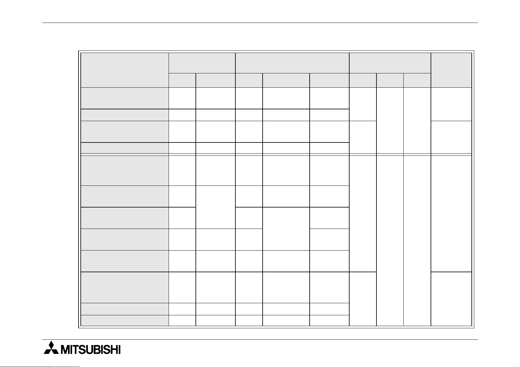
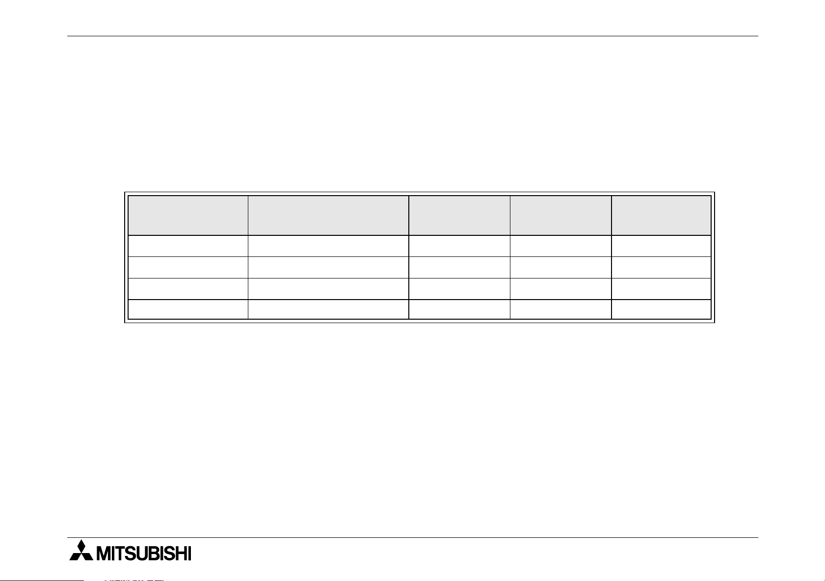
Table 1.1 : Main units
MODEL
QTY TYPE QTY TYPE
2NC
FX
FX
FX
FX
-16MT-D/UL 8
2NC
-32MT-D/UL 16 16
2NC
-64MT-D/UL 32 32
2NC
-96MT-D/UL 48 48
INPUT OUTPUT
8
24V DC
Sink
Transistor
(Sink)
POWER
SUPPLY
24V DC
+20%
-15%
Ripple
Vol tag e
(p-p)
5% or less
DIMENSIONS
mm (inches)
W H D
35
(1.4)
60
(2.4)
90
(3.5)87(3.4)
86
(3.4)
MASS
kg (lbs)
0.2
(0.44)
0.35
(0.77)
0.45
(0.99)
1-1
Page 14
FX2NC Series Programmable Controllers Introduction 1.
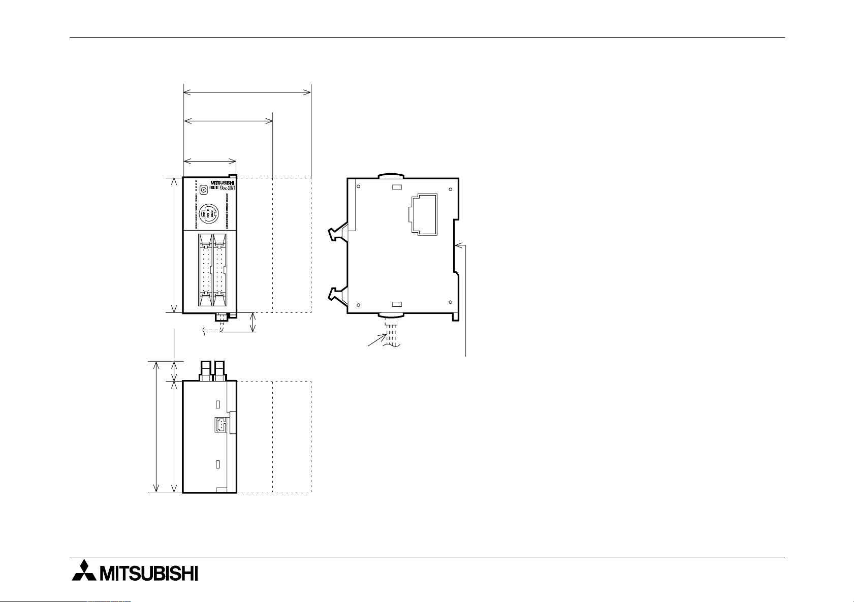
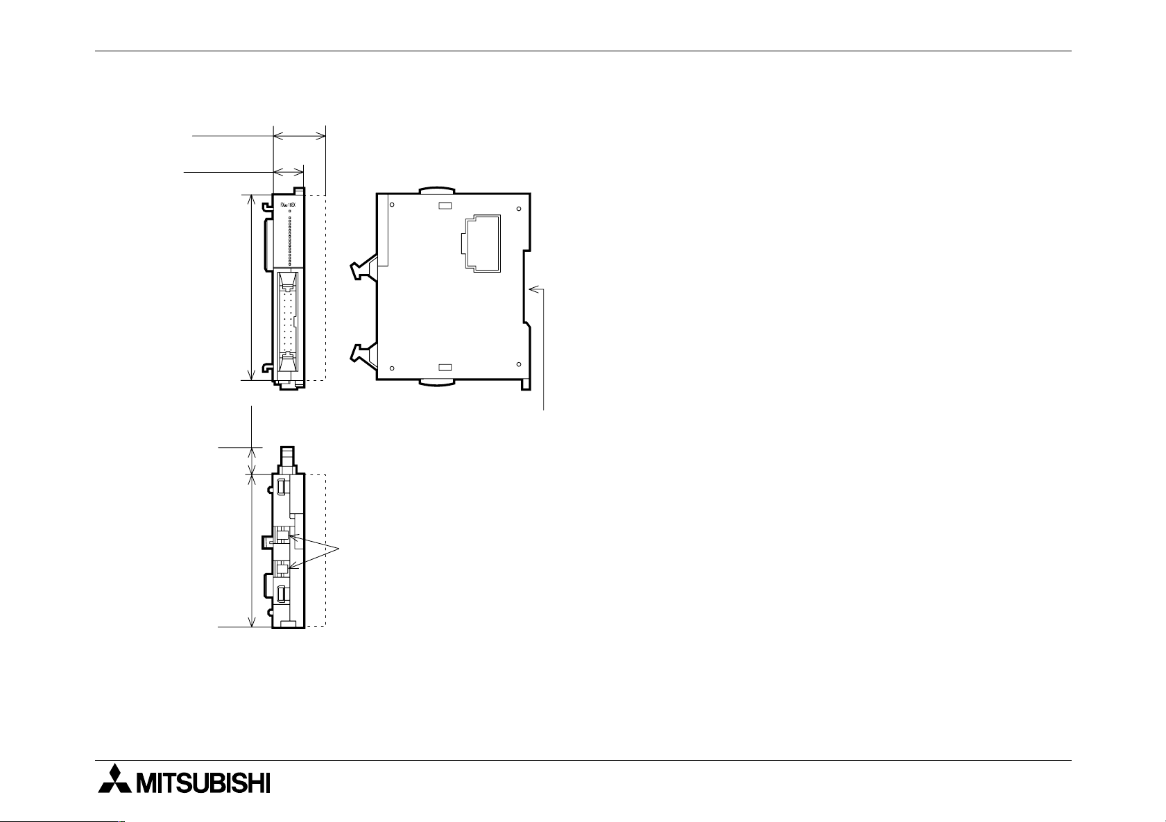
Figure 1.1 :Main unit dimensions
FX
FX
2NC
FX
2NC
35(1.38)
POWER
RUN
RUN
BATT
ERROR
X0
STOP
X2
X3
X4
X5
X6
X7 Y7
X10
X11
X12
X13
X14X1X14X14
X15
X16
X17
90(3.54)
13
(0.51)
FX
2NC
86(3.39)
-64M
2NC
60(2.36)
-32M
-16M
Y0
Y1
Y2
Y3
Y4
Y5
Y6
Y10
Y11
Y12
Y13
Y14
Y15
Y16
Y17
-96M
13
(0.5)
Power
supply
cable
UNITS: mm (inches)
DIN Rail: 35mm
(1.38)
87(3.43)
74(2.91)
1-2
Page 15
FX2NC Series Programmable Controllers Introduction 1.
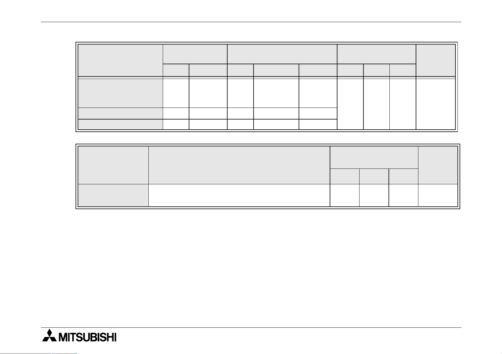
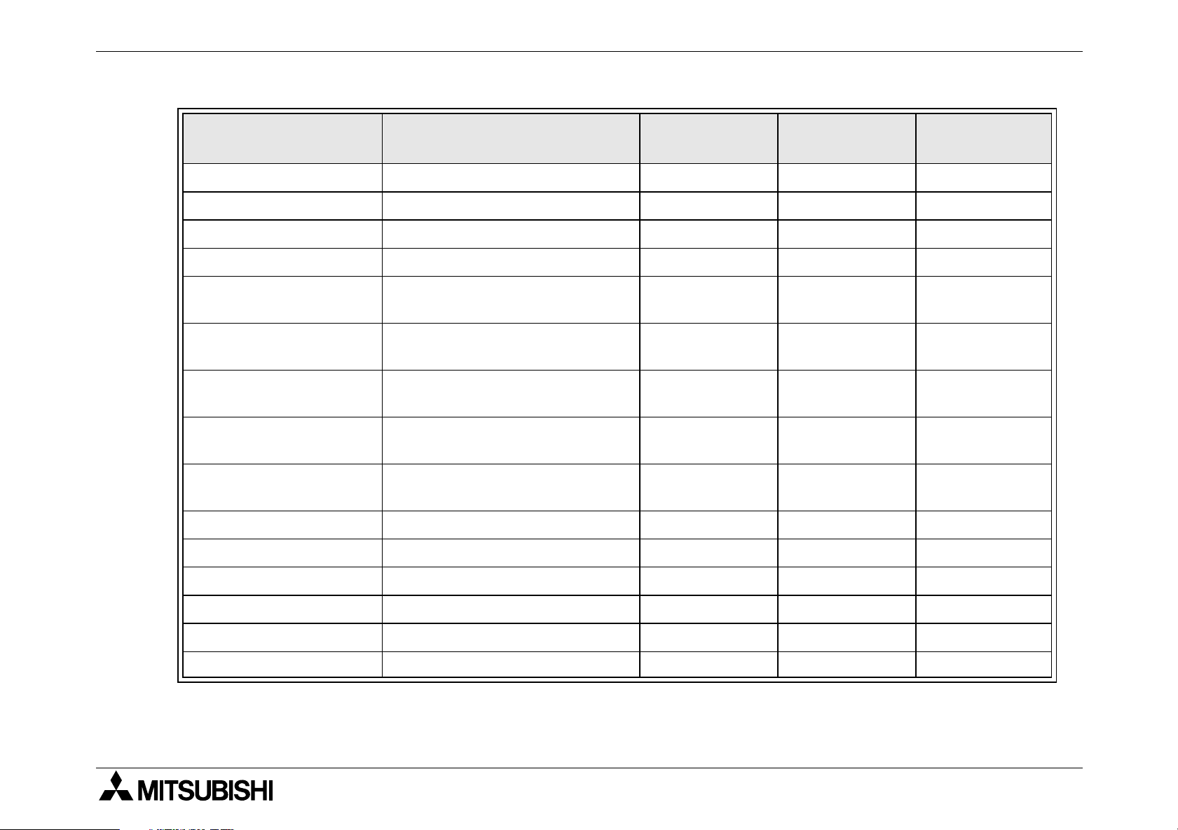
Table 1.2 : Extension blocks
MODEL
2NC
FX
FX
FX
FX
-16EX-D/UL 16
2NC
-16EYT-D/UL - - 16 Transistor Sink
2NC
-32EX-D/UL 32
2NC
-32EYT-D/UL - - 32 Transistor Sink
FX0N-8EX-UA1/UL
2N
FX
-8EX-UA1/UL
FX0N-8EX-ES/UL
2N
FX
-8EX-ES/UL
FX0N-8ER-ES/UL
2N
FX
-8ER-ES/UL
FX0N-8EYR-ES/UL
2N
FX
-8EYR-ES/UL
INPUT OUTPUT
QTY TYPE QTY DEVICE TYPE
24V DC
Sink
24V DC
Sink
-- -
-- -
110V
8
AC
-- -
inputs
8
24V DC
-- -
Sink/
44
Source
-
Relay
--8 -
DIMENSIONS
mm (inches)
W H D
14.6
(0.6)
90
(3.5)87(3.4)
26.2
(1.0)
43
(1.7)
90
(3.5)87(3.4)
MASS
kg (lbs)
0.15
(0.33)
0.2
(0.44)
0.2
(0.44)
FX0N-8EYT-ESS/UL
2N
FX
-8EYT-ESS/UL
- - 8 Transistor Source
24V DC
FX0N-16EX-ES/UL 16
Sink/
-- -
Source
FX0N-16EYR-ES/UL - - 16 Relay FX0N-16EYT-ESS/UL - - 16 Transistor Source
70
(2.8)
0.3
(0.66)
1-3
Page 16
FX2NC Series Programmable Controllers Introduction 1.
Table 1.2 : Extension blocks
INPUT OUTPUT
MODEL
QTY TYPE QTY DEVICE TYPE
24V DC
FX2N-16EX-ES/UL 16
Sink/
-- -
Source
FX2N-16EYR-ES/UL - - 16 Relay FX2N-16EYT-ESS/UL - - 16 Transistor Source
Table 1.3 : Connector conversion adapter
MODEL DESCRIPTION
FX
2NC
-CNV-IF
Extension blocks and special functions blocks
2N
of FX
and FX0N is connected by this adapter
DIMENSIONS
mm (inches)
W H D
40
(1.6)90(3.5)87(3.4)
DIMENSIONS
mm (inches)
W H D
14.6
(0.6)
90
(3.5)
(2.9)
74
MASS
kg (lbs)
0.3
(0.66)
MASS
kg (lbs)
0.15
(0.33)
1-4
Page 17
FX2NC Series Programmable Controllers Introduction 1.
Figure 1.2 :Extension block dimensions
-32E
2NC
FX
26.2(1.03)
FX
2NC
-16E
14.6(0.57)
POWER
X0
X1
X2
X3
X4
X5
X6
X7
X0
X1
X2
X3
X4
X5
X6
X7
90(3.54)
13
(0.51)
UNITS: mm (inches)
DIN Rail: 35mm
(1.38)
FX
87(3.43)
74(2.91)
0N
, FX2N Extension block dimensions →(See sec. 3.7)
Power supply connectors for
input extension blocks
1-5
Page 18
FX2NC Series Programmable Controllers Introduction 1.
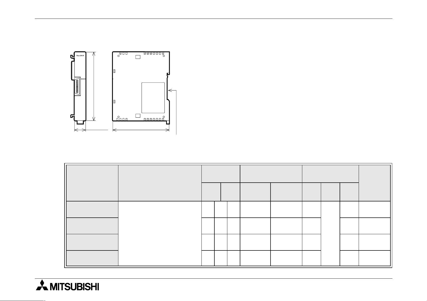
Figure 1.3 :Connector conversion adapter
UNITS: mm (inches)
90(3.54)
14.6(0.57)
74(2.91)
DIN Rail: 35mm
(1.38)
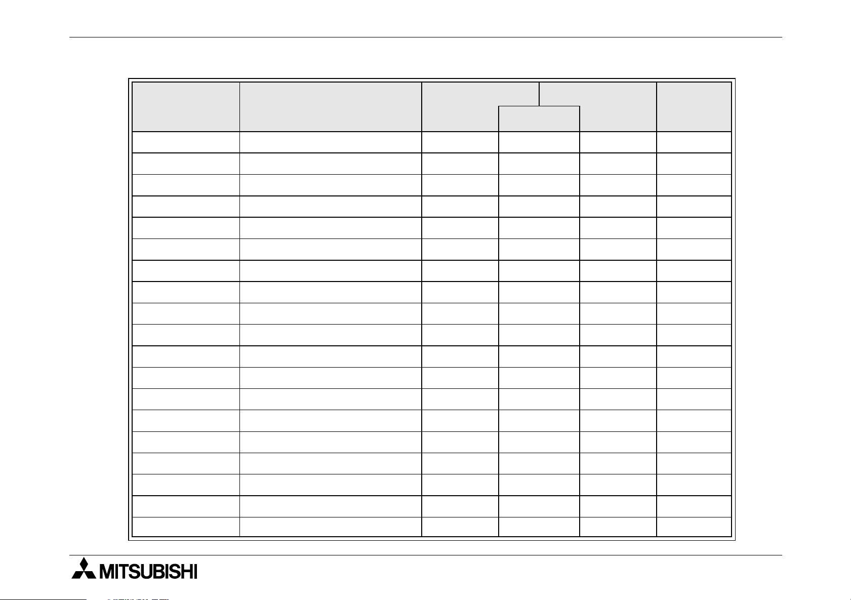
Table 1.4 :Special function blocks
NUMBER
OF I/O
MODEL DESCRIPTION
I O
FX2N-2AD
2NC
FX
-4AD - 8 - 50mA 130mA
- 8 - 20mA
Analog to digital converter
FX2N-4AD - 8 - 30mA 55mA
FX2N-8AD - 8 - 50mA 80mA
POWER SUPPLY
Internal
5V DC
External
24V DC
50mA
*1
DIMENSIONS
mm (inches)
W H D
43
(1.7)
20
(0.8)
55
90
(3.5)
(2.1)
75
(2.9)
87
(3.4)
89
(3.5)
87
(3.4)
75
(2.9)
MASS
kg (lbs)
0.2(0.44)
0.13
(0.29)
0.3(0.66)
0.4(0.88)
1-6
Page 19
FX2NC Series Programmable Controllers Introduction 1.
Table 1.4 :Special function blocks
NUMBER
OF I/O
POWER SUPPLY
MODEL DESCRIPTION
FX0N-3A
I O
Internal
5V DC
- 8 - 30mA
External
24V DC
90mA
Analog / Digital converter
FX2N-5A - 8 - 70mA 90mA
FX2N-2DA
2NC
FX
-4DA - 8 - 30mA 130mA
Digital to analog converter
- 8 - 30mA
85mA
FX2N-4DA - 8 - 30mA 200mA
FX2N-4AD-PT PT 100 probe interface - 8 - 30mA 50mA
FX2N-4AD-TC Thermo-couple interface - 8 - 30mA 50mA
FX2N-2LC Temperature control - 8 - 70mA 55mA
FX2N-1HC
- 8 - 90mA -
High speed counter
2NC
FX
-1HC - 8 - 90mA -
*1
*1
DIMENSIONS
mm (inches)
W H D
43
(1.7)
55
(2.1)
43
(1.7)
24
(0.9)
55
(2.1)
90
(3.5)
20.2
(0.8)
87
(3.4)
89
(3.5)
87
(3.4)
89
(3.5)
MASS
kg (lbs)
0.2(0.44)
0.3(0.66)
0.2(0.44)
0.13
(0.29)
0.3(0.66)
0.13
(0.29)
FX2N-1PG-E
FX2N-10PG - 8 - 120mA
Pulse output, Position
control
FX2N-10GM
- 8 - 55mA 40mA
70mA
-8- - 5W
Positioning controller
FX2N-20GM - 8 - - 10W
*2
43
(1.7)
60
(2.4)
86
(3.4)
87
(3.4)
1-7
0.2(0.44)
0.3(0.66)
0.4(0.88)
Page 20
FX2NC Series Programmable Controllers Introduction 1.
Table 1.4 :Special function blocks
NUMBER
OF I/O
MODEL DESCRIPTION
I O
FX2N-1RM-ESET
FX2N-232IF RS-232C Interface block - 8 - 40mA 80mA
FX2N-16CCL-M CC-Link Interface block *3 8 *3 - 150mA
FX2N-32CCL CC-Link Interface block - 8 - 130mA 50mA
FX2N-64CL-M CC-Link/LT Interface block *4 8 *4 190mA
FX2N-16LNK-M
FX0N-16NT Net-mini interface 8 8 20mA 60mA 0.2(0.44)
Programmable cam switch - 8 - - 5W
MELSEC-I/O LINK
Remote I/O system master
block
*5 200mA 90mA 0.5(1.1)
POWER SUPPLY
Internal
5V DC
External
24V DC
25mA
*4
DIMENSIONS
mm (inches)
W H D
55
(2.1)
55
(2.1)
85
(3.3)
43
(1.7)
111
(4.4)97(3.8)
90
(3.5)87(3.4)
MASS
kg (lbs)
0.5(1.1)
0.3(0.66)
0.4(0.88)
0.2(0.44)
0.15
(0.01)
*1 : Internal 24V DC
*2 : When the voltage of the external DC power supply is 24V DC and 5V DC, the current is 70 mA and
100 mA, respectively.
*3 : Maximum number of I/O points per system Connection is allowed as far as the following condition is
satisfied:
(Actual number of I/O points of PLC) + (Number of points occupied by special extension blocks) +
(Number of points occupied by FX
*4 : For details, refer to the FX
2N
-64CL-M user's manual.
2N
-16CCL-M: 8) + (32 x Number of remote I/O modules) ≤ 256
*5 : The value depends on the switch setting.
1-8
Page 21
FX2NC Series Programmable Controllers Introduction 1.
1.1 Unit accessories
- MPU-Main unit :
2NC
FX
-100MPCB main unit power supply cable and FX
power supply cable.
FX
2NC
Input extention block :
2NC
-10BPCB1 input extention block power supply cable.
2NC
output extention and FX0N, FX2N extention block :
-FX
-FX
I / O label kit.
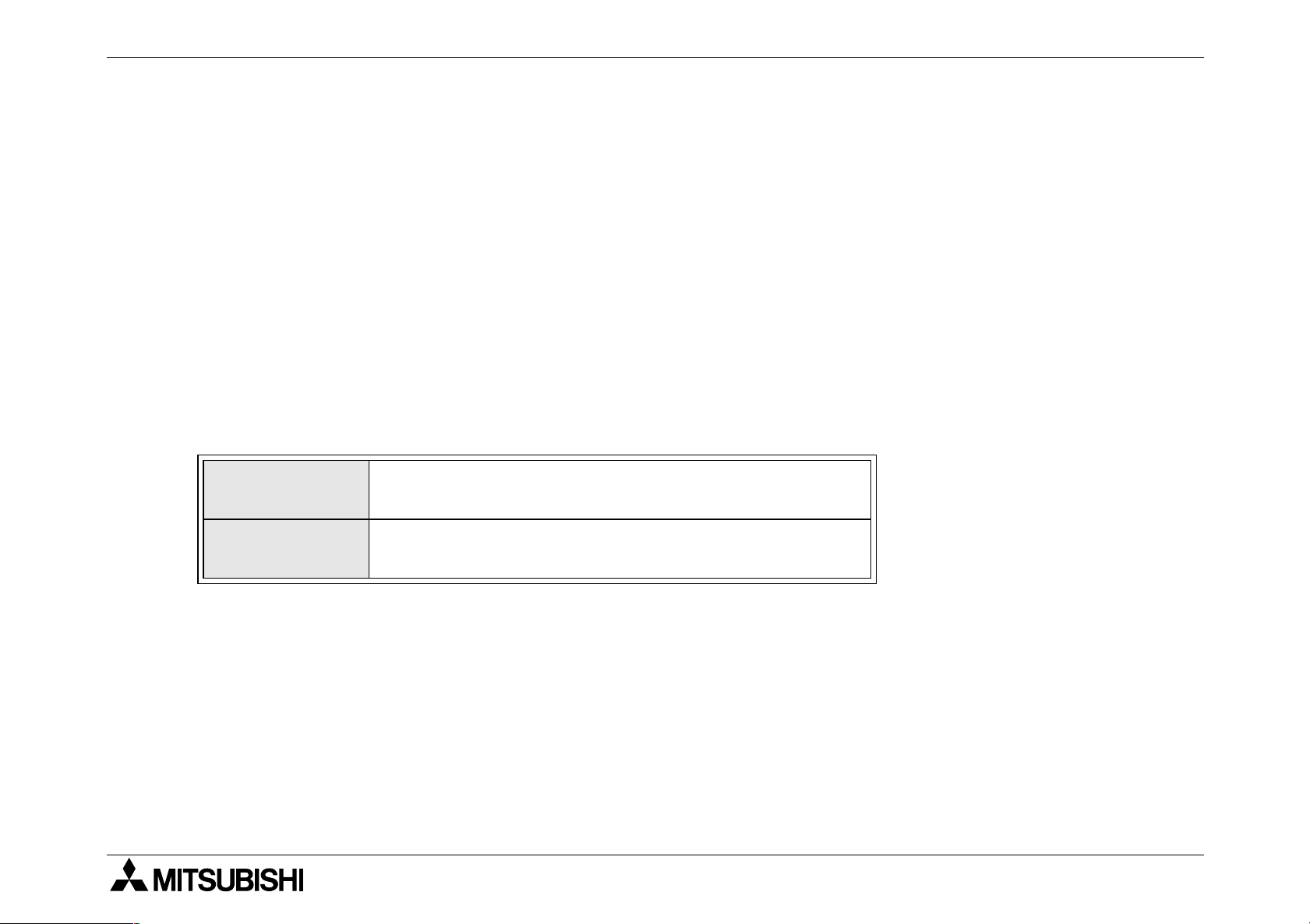
1.2 World Spec.
Table 1.5 : World / Japanese Spec.
Input
Sink / Source
Outputs
Transistor
World spec models : SINK / SOURCE.
Japanese models : ALWAYS SINK.
World spec models : ALWAYS SOURCE.
Japanese models : ALWAYS SINK.
2NC
-100BPCB input extetion block
1-9
Page 22
FX2NC Series Programmable Controllers Introduction 1.
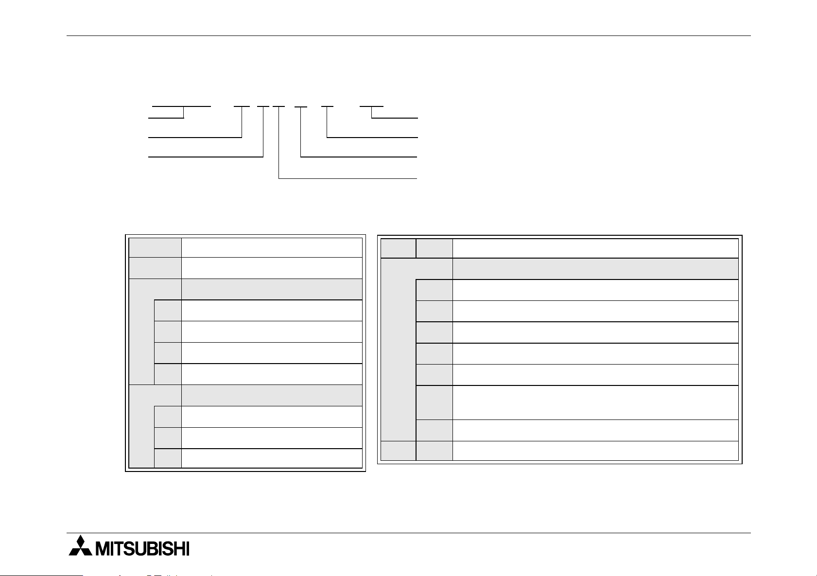
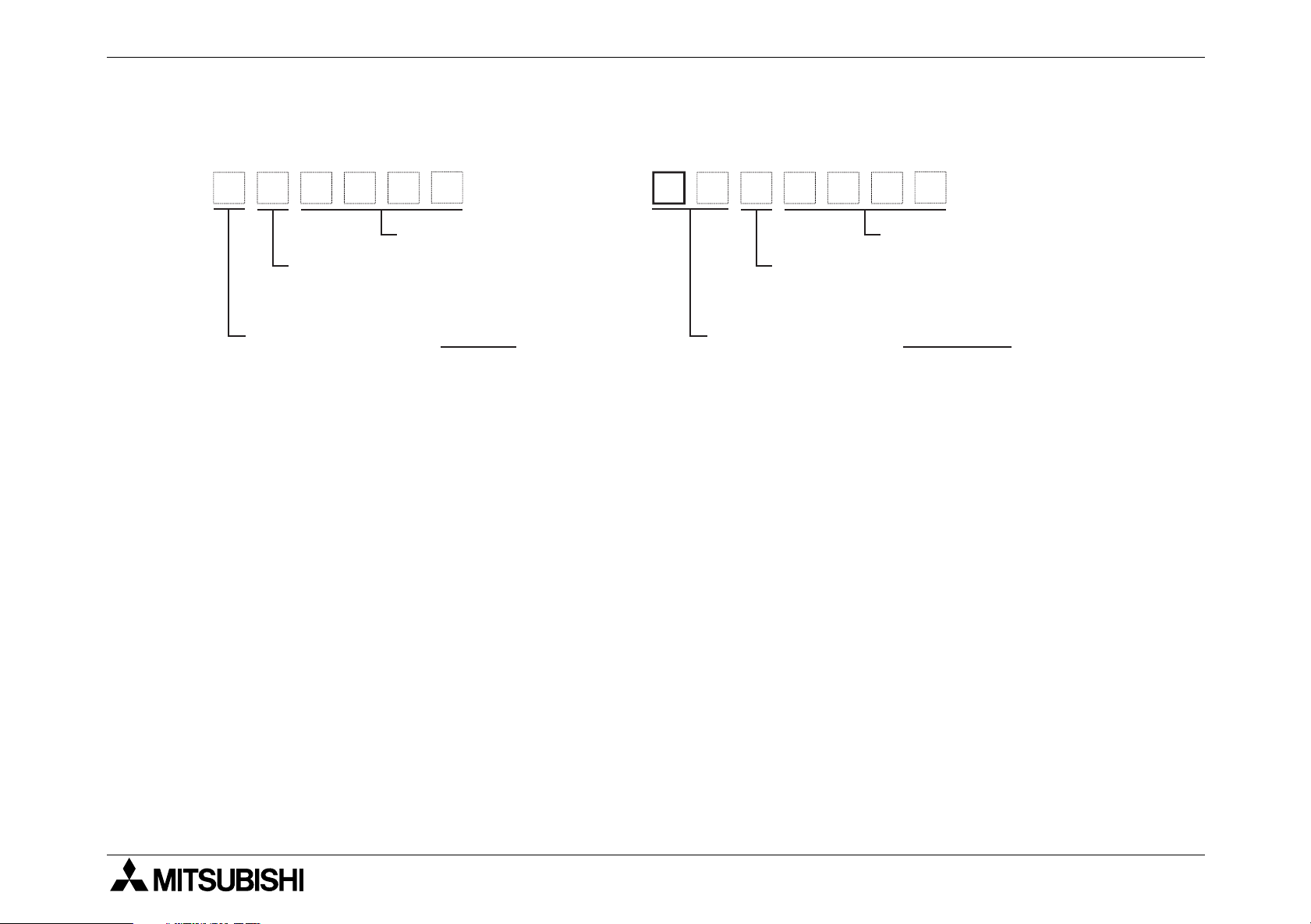
1.3 Model name
FX
2NC
-16MT--D / UL
A)
B)
C)
Table 1.6 : Model table
A)
B)
C)
PC type : FX
Total number of I / O channels
Unit type
M MPU - main unit
E Powered extension unit
EX Extension block, input
EY Extension block, output
2NC
, FX2N, FX
0N
E)
F)
G)
F)
E)
D)
T Terminal style I/O. ,Only FX
Features
Omit AC, Japanese spec.
D 24V DC Japanese spec.
DS 24V DC World spec.
DSS 24V DC World spec., DC source transistor
ES AC Power Supply World spec.,DC sink transistor
2NC
.
RRelay
D)
S Triac (SSR)
T Transistor
Output type
G)
ESS
UA1 AC Power Supply, AC inputs
UL CE,UL registered product
AC Power Supply World spec., DC source transistor
1-10
Page 23
FX2NC Series Programmable Controllers Introduction 1.
r
1.4 Serial numbers
<Product from January, 2010><Product during December, 2009 or earlier>
9Z000
Month (Example: Dec.):
1 to 9 = January to September,
X = October, Y = November, Z = December
Year (Example: 2009): Last digit of year Year (Example: 2010): Last two digit of year
1
Control number
1
0
1000
Month (Example: Jan.):
1 to 9 = January to September,
X = October, Y = November, Z = Decembe
1
Control number
1-11
Page 24
FX2NC Series Programmable Controllers Introduction 1.
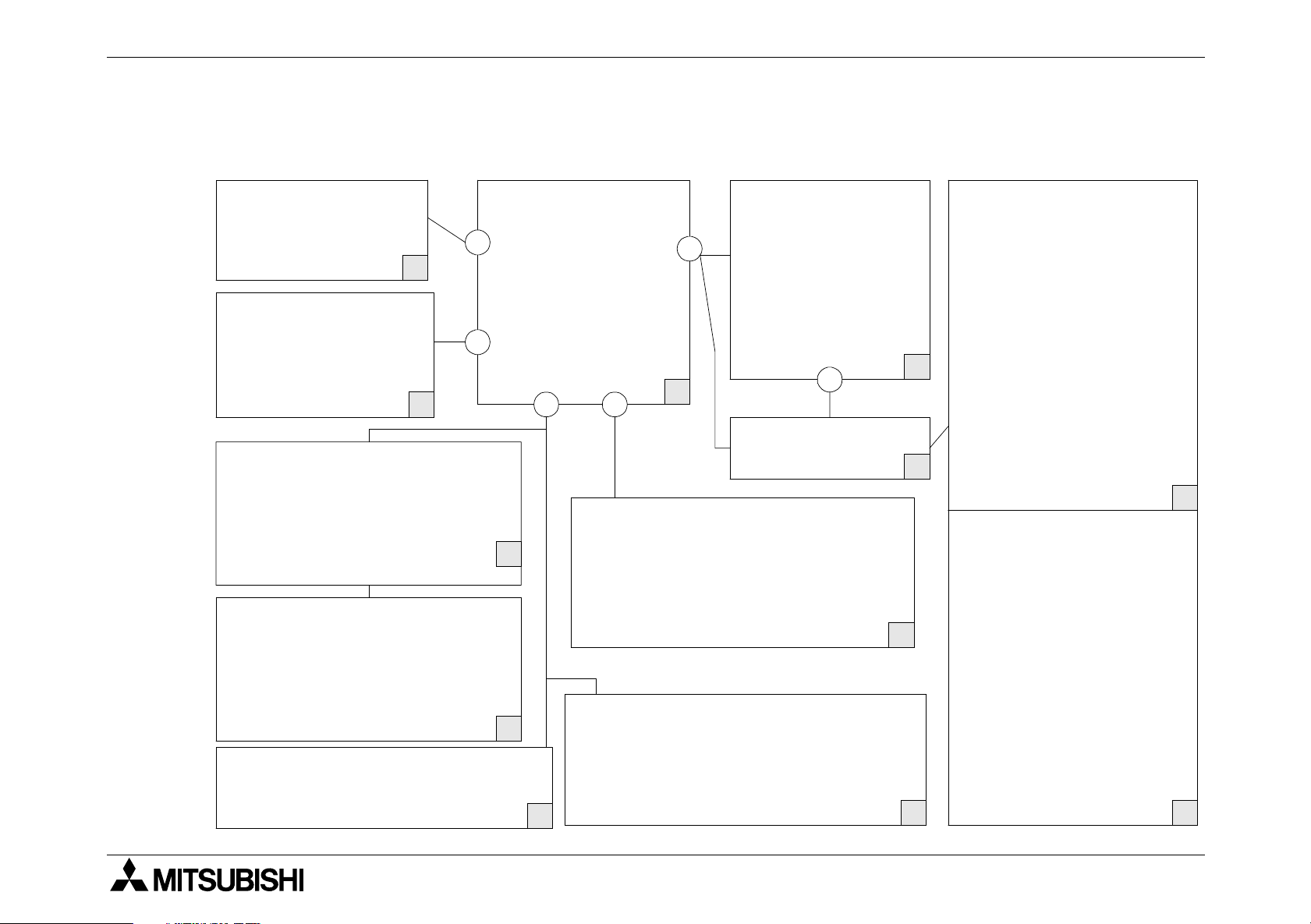
1.5 Configuration
Figure 1.4 :Schematic system
FX0N-232ADP
FX
FX
FX
-485ADP
0N
-232ADP
2NC
-485ADP
2NC
F
FX
FX
1
FX
FX
FX
FX
FX
FX
FX
-EEPROM-16
2NC
-RTC
2NC
-EEPROM-4C
2NC
-EEPROM16C
2NC
-ROM-CE1
2NC
2
G
RS 422/RS 232 CONVERTER
FX-232AW FX-232AWC
FX-232AWC-H
RS422/USB CONVERTER
FX-USB-AW
MELSEC MEDOC
FX-PCS/AT-EE
GX IEC Developer
FX-PCS/WIN-E
GX Developer
FX-30P
FX-20P-E-SET0 FX-20P-E
FX-10P-E
FX2N-16EX-ES/UL
-16EYR-ES/UL
2N
-16EYT-ESS/UL
2N
-8EX-ES/UL
0N
-8EX-UA1/UL
0N
-8ER-ES/UL
0N
-8EYR-ES/UL
0N
-8EYT-ESS/UL
0N
-8EX-ES/UL
2N
-8EX-UA1/UL
2N
-8ER-ES/UL
2N
-8EYR-ES/UL
2N
-8EYT-ESS/UL
2N
-16EX-ES/UL
0N
-16EYR-ES/UL
0N
-16EYT-ESS/UL
0N
B
C
FX
FX
FX
FX
FX
FX
FX
FX
FX
FX
FX
FX
FX
FX
FX
FX0N-3A FX2N-5A
FX
FX
FX
FX
FX
FX
FX
FX
FX
FX
FX
FX
FX
FX
-2AD FX2N-2DA
2N
-4AD FX2N-4DA
2N
-8AD FX2N-2LC
2N
-4AD-PT
2N
-4AD-TC
2N
-1HC FX2N-10PG
2N
-1PG-E
2N
-10GM FX2N-20GM
2N
-1RM-E-SET
2N
-232IF FX2N-32CCL
2N
-16CCL-M
2N
-64CL-M
2N
-16LNK-M
2N
-16NT
0N
D
E
-16MT-D/UL
2NC
-32MT-D/UL
2NC
-64MT-D/UL
2NC
-96MT-D/UL
2NC
3
FX
FX
5
FX
FX
FX
FX
FX
4
A
FX
-16EX-D/UL
2NC
-16EYT-D/UL
2NC
-32EX-D/UL
2NC
-32EYT-D/UL
2NC
-4AD
2NC
-4DA
2NC
-1HC
2NC
6
-CNV-IF
2NC
FX-16E-TB
FX-32E-TB
J
FX-16EYR-TB
FX-16EYT-TB
FX-16EX-A1-TB
L
FX-10DU-E FX-40DU-ES
K
FX-20DU-E FX-40DU-TK-ES
FX-25DU-E FX-50DU-TK(S)-E
FX-30DU-E F930GOT
I
F940GOT
H
1-12
Page 25
FX2NC Series Programmable Controllers Introduction 1.
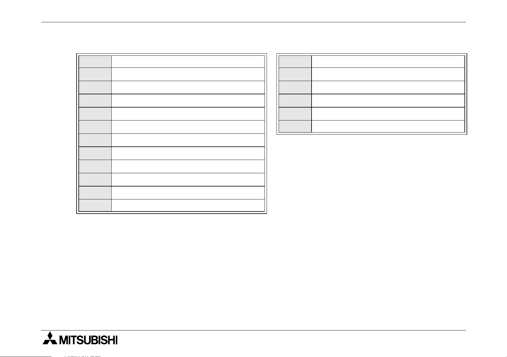
Table 1.7 : Configuration notes
A
B
C
D
E
F
G
H
I
J
K
L
Note
MPU-Main unit (Main Processing Unit)
Extension block, Special function block
Connector conversion adapter
Extension block
Special function block
Function adapters
Memory board (Real time clock)
Data access units, GOT
Dedicated programming
Computer interface
Computer software
Terminal block
c
d
e
f
g
h
Left hand side port
Memory port
Programming port
I/O port
MPU bus port
Unit bus port
When connecting peripheral equipment (programming tool or GOT [direct connection to
CPU]) via the FX
2NC
-232ADP or the FX0N-232ADP, FX
2NC
main unit should be the following
setting condition.
- Set the special data register for the communication format setting of the channel
connecting the peripheral equipment (D8120) to K0.
- Set the communication parameter to "Not set".
1-13
Page 26

FX2NC Series Programmable Controllers Introduction 1.
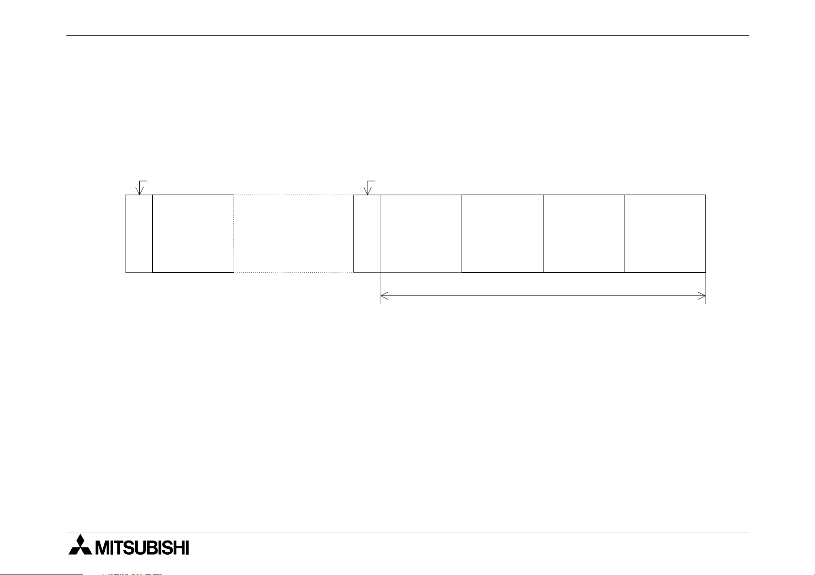
1.5.1 Summary
Connection of FX
The FX
2NC
series input extension blocks and FX
directly connected to the FX
series extension blocks only
2NC
2NC
series main unit. These input/output extension blocks can be
2NC
series output extension blocks can be
connected in the desired order. After connection, octal numbers will be assigned to the input/
output points of the extension blocks. These octal numbers are regarded as the input/output
numbers. The smallest number will be assigned to the input/output point next to the main unit,
and then sequentially increased for the subsequent input/output points.
Before connection, calculate the number of connectable input/output points by referring to Sec.
1.5.3, or quickly obtain this number using the table shown in Sec. 1.5.5.
X000-X017
FX
X: 16 points
Y: 16 points
-32MT-D/UL
2NC
X020
-
X037
16EX
16 points
X040
-
X057
16EX
16 points
16EYT
16 points
X060
-
X077
16EX
16 points
16EYT
16 points
16EYT
16 points
X100
-
X117
16EX
16 points
16EYT
16 points
Y000-Y017
Y020
-
Y037
Y040
-
Y057
Y060
-
Y077
Y100
Y117
1-14
-
Page 27
FX2NC Series Programmable Controllers Introduction 1.
Connection of FX0N and FX2N series extension blocks and function adapter
To connect the FX
connect the FX
2NC
series main unit to the FX0N or FX2N series extension blocks, be sure to
2NC
-CNV-IF connector conversion adapter first. Following the adapter, you can
connect up to 4 blocks. In addition, one special adapter can be connected to the left side of the
base unit. Before connection, calculate the number of connectable input/output points by referring to Sec. 1.5.3.
FX
-232ADP (Function adapter)
0N
FX
-D/UL
2NC
-32MT
FX
extension blocks
2NC
Series
FX
-CNV-IF (Connector conversion adapter)
2NC
FX2N-16EYR
-ES/UL
relay output
block
FX2N-232IF
RS-232C
block
4 blocks, maximum
FX2N-1PG-E
pulse output
block
FX2N-4AD
analog block
1-15
Page 28
FX2NC Series Programmable Controllers Introduction 1.
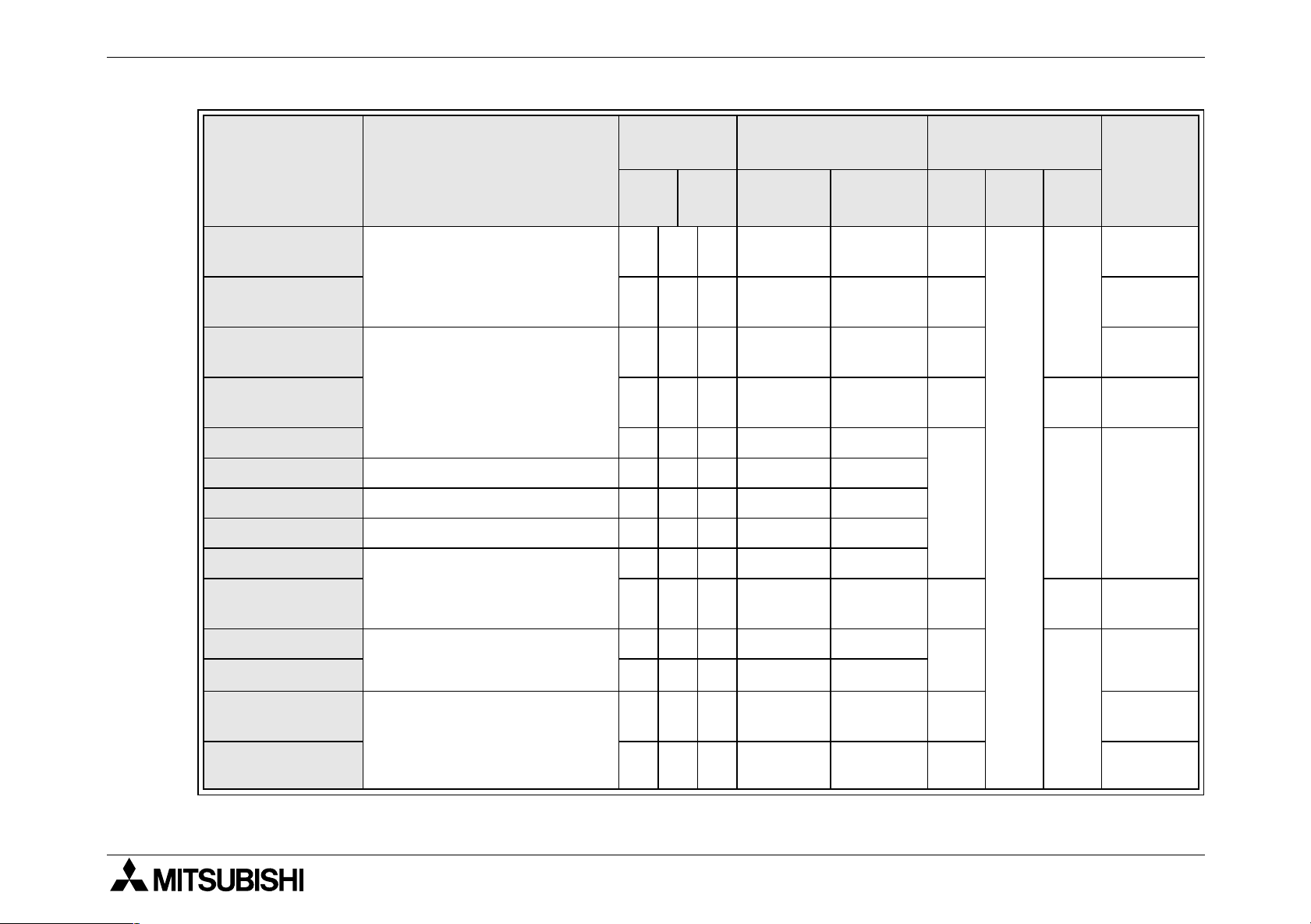
1.5.2 Current consumption and input/output points
The following tables show the current consumption and input/output points of various types of
2NC
FX
series main units, extension blocks, and special function blocks.
While referring to Sec. 1.5.3, calculate the total current consumption and total input/output values using the following main unit values (values n through q), extension block values, and
special function block values.
Table 1.8 : Base units
FX
FX
FX
FX
CURRENT CAPACITY
MODEL
2NC
-16MT-D/UL 600mA 8 8 16
2NC
-32MT-D/UL 560mA 16 16 32
2NC
-64MT-D/UL 480mA 32 32 64
2NC
-96MT-D/UL 400mA 48 48 96
n
5V DC
INPUT
o
X
OUTPUT
p
Y
TOTAL
q
1-16
Page 29
FX2NC Series Programmable Controllers Introduction 1.
.
Table 1.9 : Extension blocks
MODEL
2NC
FX
FX
FX
FX
FX
FX
-16EX-D/UL 30mA 16 - 16
2NC
-16EYT-D/UL 50mA - 16 16
2NC
-32EX-D/UL 60mA 32 - 32
2NC
-32EYT-D/UL 100mA - 32 32
0N
-8ER-ES/UL
2N
-8ER-ES/UL
FX0N-8EX-ES/UL
2N
FX
FX
FX
FX
FX
FX
FX
FX
-8EX-ES/UL
0N
-8EX-UA1/UL
2N
-8EX-UA1/UL
0N
-8EYR-ES/UL
2N
-8EYR-ES/UL
0N
-8EYT-ESS/UL
2N
-8EYT-ESS/UL
0N
-16EX-ES/UL 40mA 16 - 16
CURRENT CONSUMPTION
5V DC
25mA 4(8) 4(8)
25mA 8 - 8
25mA 8 - 8
30mA - 8 8
30mA - 8 8
INPUT
X
OUTPUT
Y
TOTAL
*1
16
0N
FX
FX
FX
FX
FX
-16EYT-ESS/UL 40mA - 16 16
0N
-16EYR-ES/UL 40mA - 16 16
2N
-16EX-ES/UL 45mA 16 - 16
2N
-16EYR-ES/UL 40mA - 16 16
2N
-16EYT-ESS/UL 180mA - 16 16
*1:8 points are used for actual input/output, however, this block should occupy 16 input/output
points.
1-17
Page 30
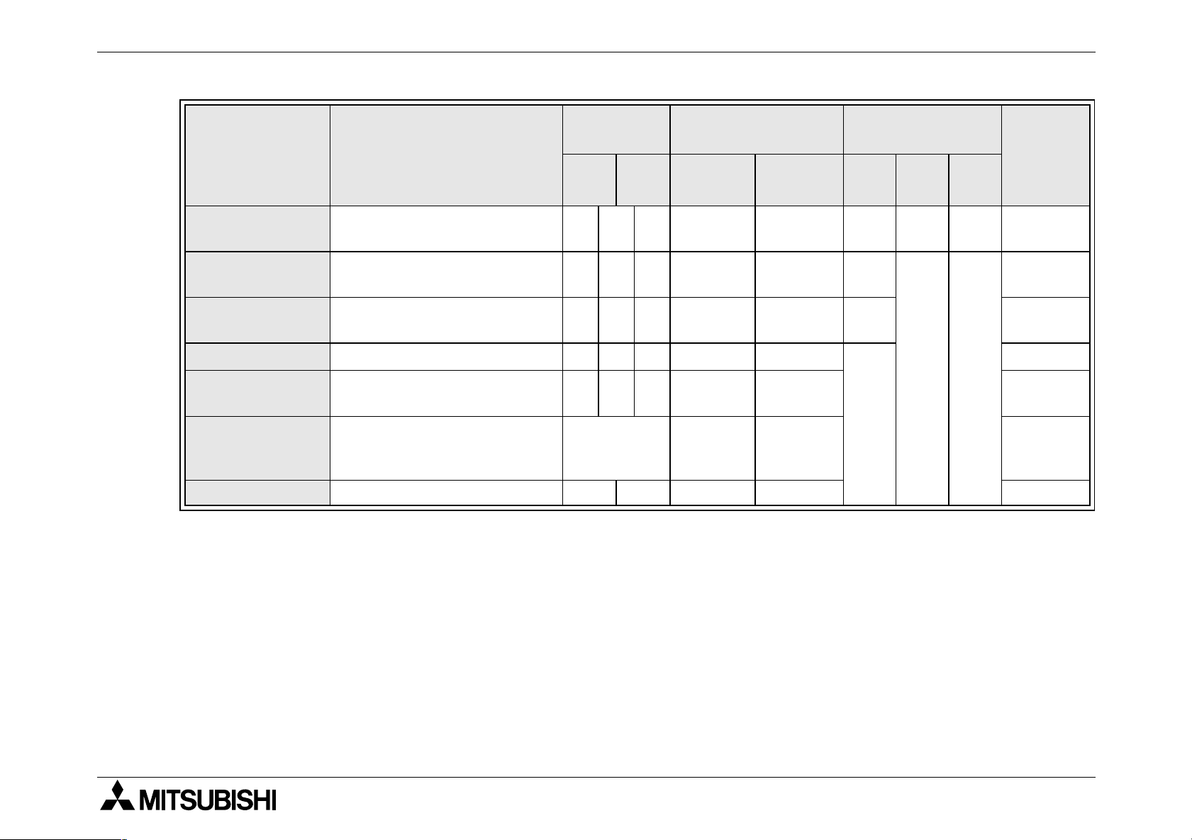
FX2NC Series Programmable Controllers Introduction 1.
Table 1.10: Special function block Function adapters
FX
FX
FX
FX
FX
FX
FX
FX
FX
FX
FX
FX
MODEL
0N
-3A 30mA - 8 - 8
0N
-16NT 20mA 8 - 8 16
2N
-2AD 20mA - 8 - 8
2N
-4AD 30mA - 8 - 8
2NC
-4AD 50mA - 8 - 8
2N
-8AD 50mA - 8 - 8
2N
-4AD-PT 30mA - 8 - 8
2N
-4AD-TC 30mA - 8 - 8
2N
-5A 70mA - 8 - 8
2N
-2DA 30mA - 8 - 8
2N
-4DA 30mA - 8 - 8
2NC
-4DA 30mA - 8 - 8
CURRENT CONSUMPTION
5V DC
INPUT
X
X/Y
OUTPUT
Y
TOTAL
FX
FX
FX
FX
FX
FX
FX
2N
-8AD 50mA - 8 - 8
2N
-2LC 70mA - 8 - 8
2N
-1HC 90mA - 8 - 8
2NC
-1HC 90mA - 8 - 8
2N
-1PG-E 55mA - 8 - 8
2N
-10PG 120mA - 8 - 8
2N
-232IF 40mA - 8 - 8
1-18
Page 31

FX2NC Series Programmable Controllers Introduction 1.
FX
FX
FX
FX
FX
FX
FX
FX
FX
FX
FX
MODEL
2N
-16CCL-M - *1 8 *1 8
2N
-32CCL 130mA - 8 - 8
2N
-64CL-M 190mA *2 8 *2 *2
2N
-16LNK-M 200mA *3 *3 *3 *3
2N
-10GM - - 8 - 8
2N
-20GM - - 8 - 8
2N
-1RM-E-SET
0N
-232ADP 200mA - - - -
2NC
-232ADP 100mA - - - -
0N
-485ADP 30mA - - - -
2NC
-485ADP 150mA - - - -
CURRENT CONSUMPTION
5V DC
*4
--8-8
INPUT
X
X/Y
OUTPUT
Y
TOTAL
FX-2PIF 290mA - - - -
*1:Maximum number of I/O points per system Connection is allowed as far as the following
condition is satisfied:
(Actual number of I/O points of PLC) + (Number of points occupied by special extension
blocks) + (Number of points occupied by FX
2N
-16CCL-M: 8) + (32 x Number of remote I/O
modules) ≤ 256
*2:For details, refer to the FX
2N
-64CL-M user’s manual.
*3:Value depends on the switch setting (16, 32, 48, 64, 96 or 128 points).
*4:Maximum of 1 unit can be connected.
1-19
Page 32

FX2NC Series Programmable Controllers Introduction 1.
1.5.3 Rules
1) Add the input/output points of the extension blocks and special functions blocks to the input/
output points of the main unit. The total number of input points should be 184 points or less,
and the total number of output points should be also 184 points or less. The total number of
input and output points should be no more than 256 points.
2) The FX
2NC
series main unit supplies the control power (5V DC) to the extension blocks and
special function blocks. For this reason, the total current consumption of all the blocks connected to the main unit should not exceed the current capacity of the main unit.
3) Next to the FX
unit, such as the FX
2NC
-CNV-IF, up to 4 blocks can be connected. To connect a special function
2N
-10GM or FX2N-1RM-E-SET, refer to the instruction manual of the cor-
responding special function block.
Calculation form for system configuration
Enter current consumption values and input/output points of the extension blocks and special
function blocks while referring to Sec. 1.5.2, and then calculate the total current value r and
total input and output points s through v. From the obtained values, judge whether the blocks
can be connected.
1-20
Page 33

FX2NC Series Programmable Controllers Introduction 1.
Table 1.11 : Calculation form
Block Model
FX
2NC
series
FX
2NC
input exten-
2NC
sion block
2NC
FX
series
FX
FX
2NC
output exten-
2NC
sion block
0N
FX
/FX2N
FX
series extension block
(4 blocks,
maximum)
Function
adapter
2-port interface
FX-2PIF mA blocks mA -
Current
consu-
mption
Number of
blocks
connected
Current
consumption
× number of
blocks
INPUT
X
X/Y
OUTPUT
Y
-16EX-D/UL 30 mA blocks mA points points
-32EX-D/UL 60 mA blocks mA points points
-16EYT-D/UL 50 mA blocks mA points points
-32EYT-D/UL 100 mA blocks mA points points
mA blocks mA points points points
mA blocks mA points points points
mA blocks mA points points points
mA blocks mA points points points
mA blocks mA -
r
Total current
consumption:
mA
s
Total input points: points
t
Total output points: points
u
Total input/output
common points: points
v
Total points: points
1-21
Page 34

FX2NC Series Programmable Controllers Introduction 1.
Judgment form
a) 5V DC control current capacity check
5V DC current capacity of main unit
(value shown in Sec. 1.5.2): mA
n
Total current consumption of all connected blocks
≥
(value written in calculation form): mA
r
b) Input/output point connection upper limit check
Total input points of all
connected blocks (value
written in calculation form ):
points
Total output points of all
connected blocks (value
written in calculation form ):
points
Total input/output points of all
connected blocks (value
written in calculation form ):
points
s
t
v
Input point connection
upper limit : 184 points
Output point
connection upper limit:
184 points
Input/output point
connection upper limit:
256 points
≥
≥
≥
Input points of main unit
(value shown in Sec. 1.5.2):
(value shown in Sec. 1.5.2):
Input/output points of main unit
(value shown in Sec. 1.5.2):
o
points
Output points of m ain unit
p
points
q
points
+ =
+ =
+ =
If all the above conditions are met, the extension and special function blocks can be connected to the base block.
points
points
points
If one of the above conditions is not met, reduce the number of input/output points or
number of blocks, or change the types of blocks to be connected.
1-22
Page 35

FX2NC Series Programmable Controllers Introduction 1.
1.5.4 System configuration example
FX
-485ADP (Function adapter) FX
0N
-CNV-IF (Connector conversion adapter)
2NC
FX
2NC
-32MT
-D/UL
Main unit
FX
2NC
16EX-
D/UL
FX
-
FX
32EX-
D/UL
series extension blocks
2NC
2NC
-
FX
2NC
32EYT-
D/UL
-
FX
2NC
32EYT-
D/UL
-
FX2N-
16EYR-
FX2N-
1PG-E
FX2N-
4AD
FX2N-
4DA
ES/UL
4 blocks, maximum
1-23
Page 36

FX2NC Series Programmable Controllers Introduction 1.
Table 1.12 : Calculation (Example)
Block Model
2NC
FX
series
FX
2NC
input exten-
2NC
sion block
2NC
FX
series
FX
FX
2NC
output exten-
2NC
sion block
0N
FX
/FX2N
series exten-
FX
FX
FX
2N
2N
sion block
FX
(4 blocks,
2N
maximum)
FX
2N
Function
adapter
FX
0N
Current
consu-
mption
-16EX-D/UL 30 mA
-32EX-D/UL 60 mA
-16EYT-D/UL 50 mA
-32EYT-D/UL 100 mA
-16EYR-ES/UL 40
-1PG-E 55
-4AD 30
-4DA 30
-485ADP 30
mA
mA
mA
mA
mA
Number of
blocks
connected
1
blocks
1
blocks
0
blocks
2
blocks
1
blocks
1
blocks
1
blocks
1
blocks
1
blocks
Current
consumption
number of
×
blocks
30
mA
60
mA
0
mA points points
200
mA points
40
mA points points
55
mA points
30
mA points
30
mA points
30
mA -
INPUT
X
16
32
OUTPUT
X/Y
Y
points points
points points
64
points
16
points
8
points points
8
points points
8
points points
2-port interface
FX-2PIF mA
0
blocks
0
mA -
r
Total current
consumption:
475
mA
s
Total input points:
t
Total output points :
u
Total input/output
common points:
v
Total points:
1-24
48
80
24
152
points
points
points
points
Page 37

FX2NC Series Programmable Controllers Introduction 1.
Judgment (Example)
a) 5V DC control current capacity check
5V DC current capacity of main unit
(value shown in Sec. 1.5.2): 560 mA
nr
b) Input/output point connection upper limit check
Input point connection
upper limit : 184 points
Output point
connection upper limit:
184 points
Input/output point
connection upper limit:
256 points
Calculation result:
The 5V DC power total current consumption value and total input/output points are in the
≥
≥
≥
≥
Input points of main unit
(value shown in Sec. 1.5.2):
(value shown in Sec. 1.5.2):
Input/output points of main unit
(value shown in Sec. 1.5.2):
o
16 points
Output points of m ain unit
p
16 points
q
32 points
Total current consumption of all connected blocks
(value written in calculation form): 475 mA
Total input points of all
+ =
+ =
+ =
connected blocks (value
written in calculation form ):
48 points
Total output points of all
connected blocks (value
written in calculation form ):
80 points
Total input/output points of all
connected blocks (value
written in calculation form ):
152 points
s
t
v
64
96
184
points
points
points
OK
OK
OK
OK
specified ranges, therefore the above system configuration is possible.
1-25
Page 38

FX2NC Series Programmable Controllers Introduction 1.
1.5.5 Quick judgment
To connect FX
2NC
series extension blocks only, use the following tables to quickly obtain the
connectable input/output points.
Example of quick judgment:
• If 96 input points are connected to the FX
2NC
-32MT-D/UL main unit, up to 112 output points
can be connected.
• If the number of output points are determined first, select the same number or a slightly
larger number from the output points (Y) area (area marked with *1). In this case, note that
you cannot increase the corresponding number of input points shown above even if the
determined number of output points is slightly smaller than the number shown in the table.
However, if the same number of output points are listed twice, you can select the larger
number of input points.
Table 1.13: FX
Input points of FX
input extension block (X)
Output points of FX
output extension block (Y)
-16M main unit (input: 8 points / output: 8 points)
2NC
2NC
series
2NC
series
0 16 32 48 64 80 96 112 128 144 160 176
176 176 160 160 144 144 128 112 112 96 80 64
←
*1
Total points including those of
main unit
192 208 208 224 224 240 240 240 256 256 256 256
1-26
Page 39

FX2NC Series Programmable Controllers Introduction 1.
Table 1.14: FX
Input points of FX
-32M main unit (input: 16 points / output: 16 points)
2NC
2NC
series
input extension block (X)
Output points of FX
2NC
series
output extension block (Y)
Total points including those of
main unit
Table 1.15: FX
Input points of FX
-64M main unit (input: 32 points / output: 32 points)
2NC
2NC
series
input extension block (X)
Output points of FX
2NC
series
output extension block (Y)
Total points including those of
main unit
0 16 32 48 64 80 96 112 128 144 160
168 160 160 144 128 128 112 112 96 80 64
200 208 224 224 224 240 240 256 256 256 256
Example of quick judgment
0 16 32 48 64 80 96 112 128 144
144 144 128 112 112 96 96 80 64 48
←
*1
208 224 224 224 240 240 256 256 256 256
←
*1
Table 1.16: FX
Input points of FX
-96M main unit (input: 48 points / output: 48 points)
2NC
2NC
series
input extension block (X)
Output points of FX
2NC
series
output extension block (Y)
Total points including those of
main unit
0 16 32 48 64 80 96 112 128
128 112 96 96 80 80 64 48 32
224 224 224 240 240 256 256 256 256
←
*1
1-27
Page 40

FX2NC Series Programmable Controllers Introduction 1.
MEMO
1-28
Page 41

FX2NC Series Programmable Controllers Terminal layouts 2.
1 INTRODUCTION
2 TERMINAL LAYOUTS
3 INSTALLATION NOTES
4 POWER SUPPLY
5 INPUTS
6OUTPUTS
7 DIAGNOSTICS
8 DISCONTINUED MODEL
9 APPENDIX
Page 42

FX2NC Series Programmable Controllers Terminal layouts 2.
Page 43

FX2NC Series Programmable Controllers
2. Terminal layouts
Terminal layouts 2.
The following selection of terminal layouts are taken from the FX
Note: All layouts are diagrammatic only and are only intended to aid the creation of wiring diagrams.
2.1 Main units
2NC
FX
X0
X1
X2
X3
X4
X5
X6
X7
COM COM
-16MT-D/UL
IN OUT
Y0
Y1
Y2
Y3
Y4
Y5
Y6
Y7
COM1 COM1
2NC
product range.
2-1
Page 44

FX2NC Series Programmable Controllers Terminal layouts 2.
2NC
-32MT-D/UL
IN OUT
X0
X1
X2
X3
X4
X5
X6
X7
COM COM
X10
X11
X12
X13
X14
X15
X16
X17
IN OUT
X0
X1
X2
X3
X4
X5
X6
X7
COM COM
X10
X11
X12
X13
X14
X15
X16
X17
Y0
Y1
Y2
Y3
Y4
Y5
Y6
Y7
COM1 COM1
Y0
Y1
Y2
Y3
Y4
Y5
Y6
Y7
COM1 COM1
Y10
Y11
Y12
Y13
Y14
Y15
Y16
Y17
Y10
Y11
Y12
Y13
Y14
Y15
Y16
Y17
IN OUT
X0
X1
X2
X3
X4
X5
X6
X7
COM COM
2NC
FX
-96MT-D/UL
IN OUT
X20
X21
X22
X23
X24
X25
X26
X27
COM COM
X30
X31
X32
X33
X34
X35
X36
X37
FX
X10
X11
X12
X13
X14
X15
X16
X17
Y20
Y21
Y22
Y23
Y24
Y25
Y26
Y27
COM2 COM2
Y0
Y1
Y2
Y3
Y4
Y5
Y6
Y7
COM1 COM1
Y30
Y31
Y32
Y33
Y34
Y35
Y36
Y37
2NC
-64MT-D/ULFX
Y10
Y11
Y12
Y13
Y14
Y15
Y16
Y17
X40
X41
X42
X43
X44
X45
X46
X47
COM COM
IN OUT
X20
X21
X22
X23
X24
X25
X26
X27
COM COM
X30
X31
X32
X33
X34
X35
X36
X37
Y20
Y21
Y22
Y23
Y24
Y25
Y26
Y27
COM2 COM2
IN OUT
X50
X51
X52
X53
X54
X55
X56
X57
Y40
Y41
Y42
Y43
Y44
Y45
Y46
Y47
COM3 COM3
Y30
Y31
Y32
Y33
Y34
Y35
Y36
Y37
Y50
Y51
Y52
Y53
Y54
Y55
Y56
Y57
2-2
Page 45

FX2NC Series Programmable Controllers Terminal layouts 2.
2.2 FX
2NC
FX
Lower
FX
Lower
-16EX-D/UL FX
IN
X0
X1
X2
X3
X4
X5
X6
X7
COM COM
2NC
-16EYT-D/UL FX
OUT
Y0
Y1
Y2
Y3
Y4
Y5
Y6
Y7
COM1 COM1
Extension blocks
2NC
X0
X1
X2
X3
X4
X5
X6
X7
Y0
Y1
Y2
Y3
Y4
Y5
Y6
Y7
Upper
Upper
Lower
Lower
2NC
-32EX-D/UL
IN
X0
X1
X2
X3
X4
X5
X6
X7
COM COM
X0
X1
X2
X3
X4
X5
X6
X7
2NC
-32EYT-D/UL
OUT
Y0
Y1
Y2
Y3
Y4
Y5
Y6
Y7
COM1 COM1
Y0
Y1
Y2
Y3
Y4
Y5
Y6
Y7
IN
X0
X1
X2
X3
X4
X5
X6
X7
COM COM
X0
X1
X2
X3
X4
X5
X6
X7
OUT
Y0
Y1
Y2
Y3
Y4
Y5
Y6
Y7
COM2 COM2
Y0
Y1
Y2
Y3
Y4
Y5
Y6
Y7
Upper
Upper
2-3
Page 46

FX2NC Series Programmable Controllers Terminal layouts 2.
2.3 FX2N and FX0N Extension blocks
S/S X1 X3
X0 X2
FX
2N
-8EX-ES/UL
FX
0N
-8EX-ES/UL
FX
2N
-8EYR-ES/UL
X4 X6
X5 X7
S/S X1 X3
X0 X2 X4 X6
Y0 Y2
FX
0N
-8EYR-ES/UL
Y4 Y6
X5 X7
COM1
Y1 Y3
COM2
Y5 Y7
FX
FX
0N
2N
-8EYT-ESS/UL
-8EYT-ESS/UL
Y0 Y2
Y4 Y6
+V0 +V1
S/S
X0 X2
Y1 Y3
FX
2N
-8ER-ES/UL
FX
0N
-8ER-ES/UL
X1 X3
COM1
FX
2N
-8EX-UA1/UL
Y0 Y2
Y5 Y7
COM1
Y1 Y3
Y1 Y3
COM2
Y0 Y2 Y4 Y6
X0 X2
FX
0N
-8EX-UA1/UL
X4 X6
Y5 Y7
COM1
X1 X3
X5 X7
S/S
FX
2N
X4X2X0 X6X4X2
-16EX-ES/UL
X7
X3X1X0X5 X6X3X1
X5 X7
+V0 Y1 Y3
Y0 Y2 Y4 Y6
FX
2N
-16EYR-ES/UL
COM1
Y7
Y5 Y7Y3Y1Y0Y5 Y6Y3Y1
Y4Y2Y0 Y6Y4Y2
COM2
+V1
+V0
FX
2N
-16EYT-ESS/UL
Y7
Y5 Y7Y3Y1Y0Y5 Y6Y3Y1
Y5 Y7
Y4Y2Y0 Y6Y4Y2
+V1
FX0N-16EX-ES/UL
X0 X2 X4 X6
S/S X1 X3 X5 X7
FX
-16EYR-ES/UL
0N
Y0 Y2 Y4 Y6
COM3
Y1 Y3 Y5 Y7
COM4
FX
-16EYT-ESS/UL
0N
Y0 Y2 Y4 Y6
+V2 Y1 Y3 Y5 Y7+V3
2-4
Page 47

FX2NC Series Programmable Controllers Installation notes 3.
1 INTRODUCTION
2 TERMINAL LAYOUTS
3 INSTALLATION NOTES
4 POWER SUPPLY
5 INPUTS
6OUTPUTS
7 DIAGNOSTICS
8 DISCONTINUED MODEL
9 APPENDIX
Page 48

FX2NC Series Programmable Controllers Installation notes 3.
Page 49

FX2NC Series Programmable Controllers
3. Installation notes
Installation notes 3.
The installation of FX
2NC
products has been designed to be safe and easy. When the products
associated with this manual are used as a system or individually, they must be installed in a
suitable enclosure. The enclosure should be selected and installed in accordance to the local
and national standards.
3-1
Page 50

FX2NC Series Programmable Controllers Installation notes 3.
3.1 Product outline
Figure 3.1:Features of the FX
N
M
2NC
I
J
G
K
PC
F
POWER
RUN
RUN
BATT
ERROR
X0
STOP
X2
X3
X4
X5
X6
X7 Y7
X10
X11
X12
X13
X14X1X14X14
X15
X16
X17
AE D
Extension block
H
POWER
Y0
Y1
Y2
Y3
Y4
Y5
Y6
Y10
Y11
Y12
Y13
Y14
Y15
Y16
Y17
X0
X1
X2
X3
X4
X5
X6
X7
X0
X1
X2
X3
X4
X5
X6
X7
POWER
Y0
Y1
Y2
Y3
Y4
Y5
Y6
Y7
Y0
Y1
Y2
Y3
Y4
Y5
Y6
Y7
L
Main unit
C
B
A O
3-2
Page 51

FX2NC Series Programmable Controllers Installation notes 3.
Table 3.1 : Feature table
A
B
C
D
E
F
G
H
J
K
L
M
Slide lock for extension I/O block
Power supply connector (Uses the 24V DC)
Din rail clip
Backup battery
Status indicators (POWER, RUN, BATT, ERROR)
Run / Stop switch
Programming port
Extension connector
I
Output indicators
Input indicators
Output connector or Output terminal
Input connector or Input terminal
Function adapter connector
N
O
Memory board / Real time clock board, connector
Input power supply connector, input power supply connector for crossover wiring
3-3
Page 52

FX2NC Series Programmable Controllers Installation notes 3.
3.2 FX
RUN or STOP of the FX
n
o
parameters.
p
RUN/STOP Control
2NC
2NC
can be controlled by:
The RUN/STOP switch mounted next to the programming port.
A standard input (X000 to X017; X000 to X007 for FX
2NC
-16M★ units) defined by the system
Remotely from a personal computer or other programming peripheral.
Note
:The FX
2NC
RUN/STOP switch n works in parallel with the RUN-input terminal o.
Please refer to table 3.2.
During remote operation the FX
2NC
RUN/STOP status is determined by the most
recently operated control.
E.g. If the RUN/STOP switch is in RUN and a remote STOP is made from a personal
computer the RUN/STOP switch must be switched to STOP then back to RUN to
switch the MPU back to RUN mode.
3-4
Page 53

FX2NC Series Programmable Controllers Installation notes 3.
Table 3.2 : RUN/STOP selection
n
RUN/STOP
n
SWITCH
RUN INPUT
o
TERMINAL
RUN ON RUN
RUN OFF RUN
STOP OFF STOP
STOP ON RUN
Figure 3.2:
STOP
POWER
RUN
RUN
BATT
ERROR
X0
STOP
X2
X3
X4
X5
X6
X7 Y7
X10
X11
X12
X13
X14X1X14X14
X15
X16
X17
Y0
Y1
Y2
Y3
Y4
Y5
Y6
Y10
Y11
Y12
Y13
Y14
Y15
Y16
Y17
no
RUN
p
FX
2NC
STATUS
nop
RUN
MPU
Remote
STOP
p
p
o
COM
RUN
COM X0 X1
Parameter setting
RUN
STOP
p
Remote
RUN
3-5
Page 54

FX2NC Series Programmable Controllers Installation notes 3.
3.3 General specifications
Table 3.3 :General Specifications
Item Description
Operating Temperature 0 to 55 °C (32 to 131 °F)
Storage Temperature -20 to 70 °C (-4 to 158 °F)
Operating Humidity 35 to 85% Relative Humidity, No condensation
storage Humidity 35 to 90% Relative Humidity, No condensation
Vibration Resistance
- Direct Mounting
Vibration Resistance
- DIN rail Mounting
Shock Resistance
Noise Immunity 1000 Vp-p, 1microsecond, 30 - 100 Hz, tested by noise simulator
Dielectric Withstand Voltage 500 V AC > 1 min, tested between all points, terminals and ground
Insulation Resistance 5 MΩ > at 500 V DC, tested between all points, terminals and ground
Ground Class D (100 Ω or less)
Working atmosphere Free from corrosive or flammable gas and excessive conductive dust
Working altitude
*1
*1
*1
10 - 57 Hz: 0.075 mm Half Amplitude
2
57 - 150 Hz: 9.8 m/s
Sweep Count for X, Y, Z: 10 times (80 min in each direction)
10 - 57 Hz: 0.035 mm Half Amplitude
57 - 150 Hz: 4.9 m/s
Sweep Count for X, Y, Z: 10 times (80 min in each direction)
147m/s2 Acceleration, Action Time: 11 ms
3 times by half-sine pulse in each direction X, Y, and Z
<2000m
*2
Acceleration
2
Acceleration
*1 The criterion is shown in IEC61131-2.
*2 Do not use the PLC under pressure higher than the atmospheric pressure. Doing so may
damage the PLC.
3-6
Page 55

FX2NC Series Programmable Controllers Installation notes 3.
3.4 PC mounting arrangements
To prevent a rise in temperature, mount the units to walls. Never mount them to the floor or ceiling of an enclosure.
Figure 3.3 Single row arrangement
Figure 3.4 Double row arrangement using extension cable FX
(650mm (25.59 inches); supplied separately).
Figure 3.2 :
FX
CPU
A
> 50mm(1.97 inches)
A
2NC
A
-16EX-D/UL
2NC
FX
-32EX-D/UL
2NC
FX
AA
Figure 3.4 :
A
A
A
FX
2NC
CPU
FX0N,FX
Extension
blocks
2N
0N
-65EC
A
-16EX-D/UL
2NC
FX
A
-CNV-IF
2NC
FX
A
Extension cable
FX
-65EC
0N
A
A
> 50mm(1.97 inches)
3-7
Page 56

FX2NC Series Programmable Controllers Installation notes 3.
Caution
• Units should mot be installed in areas subject to the following conditions: excessive or
conductive dust, corrosive gas (salt air, Cl
2
, H2S, SO2, NO2, etc.) or flammable gas,
moisture or rain, excessive heat, regular impact shocks or excessive vibration.
• Take special care not to allow debris to fall inside the unit during installation e.g. cut
wires, shavings etc. Once installation is complete remove the protective paper band: to
prevent overheating.
3-8
Page 57

FX2NC Series Programmable Controllers Installation notes 3.
Remove
Locks the clip.
When DIN rail is
When directly installed
installed
(before shipment)
3.5 Connection of extension blocks to main unit
1) Remove the connector cover from the right
side of the main unit.
2) Slide up the slide lock of the main unit, and
then connect an extension block.
3) Slide down the slide lock to lock the extension block.
Connect the other extension blocks in the
same way.
3.6 DIN rail mounting
The DIN 46277 rail (35 mm, 1.4 inches) can be directly
installed on the FX
(Do not use any screws for this installation.) To remove
2NC
Figure 3.3 :
Slide lock
Slide lock
Main unit Extension block
Figure 3.6 :
series programmable controller.
the main body, slightly slide down the DIN rail mounting
clip. Slide the clip farther, and the rail will be locked with
the clip left open.
To connect the FX
2N
series extension blocks, slide the
DIN rail mounting clip in the direction of the arrow as
shown to the right.
3-9
Page 58

FX2NC Series Programmable Controllers Installation notes 3.
3.7 Direct mounting
Figure 3.7 :Group1
2N
*: FX
= 4.5mm (0.18)
80(3.15)
90(3.55)*
4(0.16)
A
∅
UNITS: mm (inches)
Table 3.4 :
MODEL A MODEL A MODEL A
-1RM is 111(4.37)
2N
FX
FX
FX
-5A
2N
-4DA FX2N-2DA
2N
-4AD FX2N-2AD FX0N-232ADP
FX2N-2LC 55 (2.16) FX2N-1PG-E
FX2N-10PG
43 (1.69)
2N
FX
-4AD-PT FX2N-32CCL FX0N-485ADP
55 (2.16)
2N
FX
FX2N-1HC FX2N-16LNK-M FX2N-8E
-4AD-TC FX2N-64CL-M FX0N-8E
43 (1.69)
FX2N-232IF FX0N-3A FX2N-16CCL-M 85 (3.35)
2N
FX
-1RM FX0N-16NT
3-10
Page 59

FX2NC Series Programmable Controllers Installation notes 3.
80(3.15)
90(3.55)
70(2.76)
60(2.36)
FX -4DA
2NC
Figure 3.8:Group2
20(0.79)
0N
-16E
40(1.57)
*
FX2N-16E
80(3.15)
90(3.55)
FX
V1+
PW
I1+
COM1
V2+
I2+
COM2
V3+
I3+
COM3
V4+
I4+
COM4
90(3.55")
24+
24+
24-
24-
*: FX
*: FX
*: FX
24V
D/A
2NC
-4DA is 24.2 (0.96)
2NC
-4AD is 20.2 (0.8)
2NC
-1HC is 20.2 (0.8)
98(3.86")
90(3.55")
105(4.14")
FX
2N
-8AD
67(2.64")
75(2.96")
UNITS: mm (inches)
3-11
Page 60

FX2NC Series Programmable Controllers Installation notes 3.
16.1(0.64)
10
(0.40)
90(3.55)
65.5(2.58)
19.1
(0.76)
Figure 3.9:Side view
87(3.42)*
* : FX2N-232IF is 85 (3.35)
FX
FX
FX
2NC
-232ADP
2NC
-485ADP
2N
-1RM is 97(3.82)
FX2N-10PG
9(0.35)
FX
0N
-232ADP is 68(2.68)
9(0.36)
74(2.92)
87(3.43)
UNITS: mm (inches)
3-12
Page 61

FX2NC Series Programmable Controllers Installation notes 3.
75(2.96)
8(0.32)
15(0.60)
74(2.92)
FX
FX
FX
2NC
2NC
2NC
FX
FX
-4DA
-4AD
-1HC
-232ADP
2NC
2NC
-485ADP
FX
2N
-8AD
9*
(0.36)
7(0.28)
74(2.92)
* : FX
2NC
-485ADP is 4(0.16)
UNITS: mm (inches)
3-13
Page 62

FX2NC Series Programmable Controllers Installation notes 3.
3.8 Extension cable installation
To connect extension blocks next to the FX
2NC
-CNV-IF block, use the FX0N-30EC or FX0N65EC extension cable. Note that only one extension cable can be used for one system. In addition, to connect extension blocks, use the FX
2N
-CNV-BC connector conversion adapter as
shown in the following figures.
Figure 3.10:
Connection example 1
FX
FX
2NC
series main unit
2NC
or
series extension block
FX
2NC
FX0N-30EC/FX0N-65EC
-CNV-IF
FX0N/FX2N series
extension block
FX2N-CNV-B C
Figure 3.11:
Connection example 2
FX0N-30EC/FX0N-65EC
FX
FX
2NC
series m ain u nit
2NC
or
series extension block
FX
-CNV-IF
2NC
/FX2N series
FX
0N
extension block
FX2N-CNV-B C
/FX2N series
FX
0N
extension block
3-14
Page 63

FX2NC Series Programmable Controllers Installation notes 3.
3.9 General notes
Always ensure that mounted units and blocks are kept as far as possible from
high-voltage cables, high-voltage equipment and power equipment.
3-15
Page 64

FX2NC Series Programmable Controllers Installation notes 3.
3.10 Memory Board installation
Figure 3.12:Installation Figure 3.13:Removal
1) Turn off the power of the programmable
controller.
2) Remove the cover from the memory
board installation section.
3) Connect the memory board to the con-
nector while carefully inserting the pins.
1) Turn off the power of the programmable
controller.
2) Remove the cover from the memory
board installation section.
3) Slowly pull up the lower section of the
memory board, and completely remove
the board.
• Before removing or installing the memory board, be sure to turn off the power.
• If the memory board is removed or installed with the power on, the memory board
may be damaged.
• During memory board removal or installation, be careful not to directly touch any
electronic parts.
3-16
Page 65

FX2NC Series Programmable Controllers Installation notes 3.
3.11 Wiring techniques
The wiring of FX
2NC
products has been designed to be safe and easy. If during the installation
of these products or associated products concern is felt, please contact a professional electrician who is trained to the local and national standards applicable to the installation site.
Wiring cautions
• Do not run input signals in the same multicore cable as output signals or allow them to
share the same wire.
• Do not lay I/O signal cables next to power to power cables or allow them to share the
same trunking duct. Low voltage cables should be reliably separated or insulated with
regard to high voltage cabling.
• Where I/O signal lines are used over an extended distance consideration for voltage
drop and noise interference should be made.
3-17
Page 66

FX2NC Series Programmable Controllers Installation notes 3.
3.12 Termination of connector style I/O
The I/O connector should be the 20-pin type and should conform to MIL C 83503 of Military
Standard.
This type of connector is also used for FX
2C
series programmable controllers.
The output connectors of the main unit and the connector-type 16-point output extension
blocks are the 16-point common type (8-point common type for the FX
2NC
-16MT).
These output connectors have two COM1 to COM3 pins that are connected to each other
inside the programmable controller. To connect the line to an external unit, shortcircuit
these two pins at the external circuit so that the load of each pin can be reduced.
3-18
Page 67

FX2NC Series Programmable Controllers Installation notes 3.
3.13 Termination of screw terminals
Cables terminating at a screw terminal of an FX2N and FX0N product should be fitted with insulated crimp terminals, see example shown. Terminals screws should be tightened to between
0.5 to 0.8 Nm. Screw terminals must be secured to prevent a loose connection from causing a
malfunction. Failure to do so may cause equipment failures or malfunctions.
Figure 3.14:
• When one wire is connected to one terminal.
6.2mm
(0.24")
or less
φ 3.2
(0.13")
6.2mm
(0.24")
or less
φ 3.2
(0.13")
• When two wires are connected to one terminal.
φ 3.2
(0.13")
6.2mm
(0.24")
or less
φ 3.2
(0.13")
6.3mm
(0.25")
or more
6.2mm
(0.24")
or less
Caution
6.3mm
(0.25")
or more
Terminal
screw
Terminal
Terminal
Terminal
screw
Terminal
Crimp
terminal
Crimp
terminal
Make sure to turn OFF the power before starting any wiring work.
3-19
Page 68

FX2NC Series Programmable Controllers Installation notes 3.
3.14 Termination of connector style I/O cables
Standard, pre-terminated cables are available from Mitsubishi in 1.5, 3 and 5 meter (4.9, 9.8
and 16.4 ft) lengths. However, users are encouraged to make their own cables to the lengths
they require. The following table identifies connectors and cable requirements;
Figure 3.15:
FX
2NC
n op q
Table 3.5 :
MODEL LENGTH
FX-16E-500CAB-S 5m (16.4)
FX-16E-150CAB 1.5m (4.9)
FX-16E-300CAB 3m (9.8)
FX-16E-500CAB 5m (16.4)
FX-16E-150CAB-R 1.5m (4.9)
FX-16E-300CAB-R 3m (9.8)
FX-16E-500CAB-R 5m (16.4)
n o p q
20 Pin
connector
20 Pin
connector
20 Pin
connector
No connector Single wire Input switch or Loads
20 Pin
connector
20 Pin
connector
Flat cables
Round
cables
TERMINAL BLOCK
FX-16E-TB
x
FX-32E-TB
x
FX-16EX-A1-TB
x
FX-16EYR-TB
x
FX-16EYT-TB
x
( ): ft
3-20
Page 69

FX2NC Series Programmable Controllers Power supply 4.
1 INTRODUCTION
2 TERMINAL LAYOUTS
3 INSTALLATION NOTES
4 POWER SUPPLY
5 INPUTS
6OUTPUTS
7 DIAGNOSTICS
8 DISCONTINUED MODEL
9 APPENDIX
Page 70

FX2NC Series Programmable Controllers Power supply 4.
Page 71

FX2NC Series Programmable Controllers
4. Power supply
Table 4.1 : Power requirements
Power supply 4.
FX
16MT-D/UL
2NC
-
FX
2NC
-
32MT-D/UL
FX
2NC
-
64MT-D/UL
FX
2NC
-
96MT-D/UL
Power supply 24V DC +20%, -15% Ripple Voltage (p-p) 5% or less
Max. allowable momentary power
5ms (5ms > PC = RUN, 5ms < PC = STOP)
failure period
Fuse (size) rating 250V 3.15A (3A) 5φ×20mm (0.2×0.79 inches)
In-rush current 30A or less 0.5ms/24V DC
Power consumption *1 6W 8W 11W 14W
*1 Includes the input current (7 or 5 mA per point).
Table 4.2 :Power consumption of FX
extension blocks
2NC
When connecting extension blocks, add the values shown below to the power consumption
value of the main unit.
Type Model Power consumption
2
2
Input extension
FX
FX
2NC
-16EX-D/UL
2NC
-32EX-D/UL
2.2W *
4.2W *
2NC
Output extension
FX
FX
Special extension See sec. Table 1.4
-16EYT-D/UL 0.35W
2NC
-32EYT-D/UL 0.7W
*2 Includes the input current (5 mA per point).
4-1
Page 72

FX2NC Series Programmable Controllers Power supply 4.
1 +
2 -
3 Ground
Main unit
- To supply the power to the main unit, use the power cable FX
-100MPCB.
2NC
- To supply the power to an input extension block, use the power cable FX
To supply the power to the second input block or later, perform crossover wiring using the
power cable FX
-10BPCB1.
2NC
Figure 4.1 : Connection of power supply cables
Green
Ground
Main unit
Input
Output
Input
Red+
Black-
Red+
Black-
Terminal layout of power
supply connector
Input block
2NC
1
2
1
2
-100BPCB.
Upper
Lower
Protective
cover
The lower power connector is provided for
crossover wiring to a later input block.
It is covered with a protective cover at the
time of shipment from the factory.
4-2
Page 73

FX2NC Series Programmable Controllers Power supply 4.
Three types of power cables shown below are offered. and are offered with the main
unit, and is offered with an input extension block.
C
A
B
Table 4.3 :
Type Application Model name Length
Power cable for main unit
A
Input power cable for input extension
B
block
Input power cable for input extension
C
The crossover cable can be wired across up to four 16-point output blocks. To supply the
block (for crossover wiring)
C
FX
FX
FX
power to an input block beyond four output blocks, use the cable .
-100MPCB
2NC
-100BPCB
2NC
-10BPCB1
2NC
1m(3.3ft)
1m(3.3ft)
0.1m(0.3ft) Input extension block
B
Product in same
package
Main unit
2N
For the 24V DC power source of the FX or FX
series programmable controllers, the correction value should be written in data register D8008; a special data register that sets the
power failure detection period. However, for the FX
2NC
series programmable controllers, it
is not necessary to write the correction value.
The data stored in the D8008 register will be automatically corrected by the system program. Do not modify the D8008 data.
4-3
Page 74

FX2NC Series Programmable Controllers Power supply 4.
11
Figure 4.2 : EX.wiring
EX.FX
DC/DC
EX.FX
EX.FX
2NC
2NC
2NC
-16M
24V DC5V DC
-16EX
-16EX
u
v
w
*1
t
*1
MC
PL
r
o
MC
q
n
p
Power supply 24V DC +20% -15%
n
Ripple voltage (p-p) 5% or less
Circuit protector or Fuse
o
Emergency stop
p
Power supply switch
q
Power ON pilot indicator
r
Power supply for loads
s
Grounding resistor 100Ω or less (class D)
t
Fuse
u
Main unit
v
Input extension blocks
w
Output extension block
EX.FX
2NC
-16EYT
w
11
MC MC
s
s
*1 It is recommended to use the same power
source to power the main unit, input extension
blocks and special function blocks. If two sources
are required, follow the below guidelines:
- Supply power to the input extension blocks and
special function blocks before or at the same
time the main unit is powered.
- The power supplies may be cut the same time
after ensuring system safety.
4-4
Page 75

FX2NC Series Programmable Controllers Power supply 4.
4.1 Power supply cautions
As shown in the following figure, supply 24V DC to the main unit, special function blocks,
and data access unit from the same power source.
Figure 4.3 : Use of same power source
Communication cable
Main Unit Extension
blocks
FX
24V D C +20% 5% ripple (p-p) or less
-15%
-CNV-IF
2NC
Data access
unit
4-5
Page 76

FX2NC Series Programmable Controllers Power supply 4.
If the power has to be supplied from two power sources due to low capacity of the DC power
supply unit, etc., be sure to connect the minus lines of the two power supply units.
Figure 4.4: Connection of minus lines
Com munication cable
Main Unit Extension
FX
24V DC +20% 5% ripple (p-p) or less
-15%
-CNV-IF
2NC
4.2 Earthing / Grounding
Use a cable at least 0.2mm2 (AWG24) to ground equipment. Ground resistance must be
less than 100Ω (class D). Note that the ground cable must not be connected to the same
ground as the power circuits. Grounding is recommended but if a proper ground cannot be
provided the PC will still operate correctly without being grounded.
blocks
Data access
unit
4-6
Page 77

FX2NC Series Programmable Controllers Inputs 5.
1 INTRODUCTION
2 TERMINAL LAYOUTS
3 INSTALLATION NOTES
4 POWER SUPPLY
5 INPUTS
6OUTPUTS
7 DIAGNOSTICS
8 DISCONTINUED MODEL
9 APPENDIX
Page 78

FX2NC Series Programmable Controllers Inputs 5.
Page 79

FX2NC Series Programmable Controllers
5. Inputs
5.1 24V DC input specifications
Inputs 5.
Table 5.1 :FX
Input voltage 24V DC +20%, -15%
Input current 24V DC, 7mA 24V DC, 5mA 24V DC, 5mA
Input switching
current
Response time 10ms
Variable response time
Circuit isolation Photocoupler
Operation indication LED is lit
input specifications
2NC
FX
extension block
X0 Æ X7 X10 Æ
OFF Æ ON >4.5mA >3.5mA >3.5mA
ON Æ OFF <1.5mA
X000-X017 0-60ms
2NC
(FX
main unit,
2NC
∞
-16M : X000-X007)
FX0N, FX2N Extension block
---
5-1
Page 80

FX2NC Series Programmable Controllers Inputs 5.
5.1.1 Typical wiring
Figure 5.1 : sink
➊
➋
COM COM
NPN
➌➍➎
X0 X1 X2 X3
➐
COM COM
➏
➌➎
X0 X1 S/S X0 X1 X2 X3
➒➓➑
5-2
Page 81

FX2NC Series Programmable Controllers Inputs 5.
Table 5.2 : Item check
n
o
p
q
r
s
t
u
v
w
External power supply 24V DC +20% -15%
NPN proximity sensor
Switch
Push button
Contact
Rotary switch
MPU main processing unit (main unit)
2NC
FX
FX
FX0N, FX2N Extension block
Input extension block
2NC
-CNV-IF Connector conversion adapter
5-3
Page 82

FX2NC Series Programmable Controllers Inputs 5.
COM
COM
X
Extention
block (Sink)
*: X10→X 4.3 k
Ω
3.3 kΩ*
24V DC
+20%
-15%
Next input
block
5.1.2 Input circuit connection
Figure 5.2 : FX
24V DC
+20%
-15%
*: X10→X 4.3 k
Main unit and FX
2NC
Main unit
(Sink)
3.3 kΩ*
X
COM
COM
Ω
Extension block
2NC
5-4
Page 83

FX2NC Series Programmable Controllers Inputs 5.
Figure 5.3 : FX2N and FX0N Extension block
24V DC
+20%
-15%
X
S/S
Sink
4.3 k
Ω
24V DC
+20%
-15%
X
S/S
Source
4.3 k
Ω
5-5
Page 84

FX2NC Series Programmable Controllers Inputs 5.
5.1.3 Diodes and inputs connected in series;
Vdrop across the diode Max. 4V
No more than 2 LEDs should be connected in series.
Figure 5.4 : Series diodes
Ex. Sink
FX
FX
Main unit
2NC
2NC
Extention
block
X
COM
COM
FX
0N,
FX
2N
Extention block
X
S/S
5-6
Page 85

FX2NC Series Programmable Controllers Inputs 5.
5.1.4 Resistors and inputs connected in parallel;
Parallel resistance Rp: FX
2NC
= 15kΩ. If resistance Rp is less than the stated value, then add
Rb. See equation 1 for Rb calculation.
Alternatively; Current leakage: FX
2NC
= 1.5mA. If the current leakage is greater than the stated
value, then add Rb. See equation 2 for Rb calculation.
Figure 5.5 : Parallel LED
Rp
4
≤
Rb
Rb
Rp
15 -
+24V
6
≤
Ι
- 1.5
LED
Rb
Rp
Eqn 1 :
Eqn 2 :
2NC
FX
FX
Main unit
2NC
Extention
block
X
COM
5-7
Page 86

FX2NC Series Programmable Controllers Inputs 5.
5.2 AC110V input Extension block
Table 5.3 : FX
-8EX-UA1/UL, FX2N-8EX-UA1/UL input specification
0N
Input voltage
Input impedance
Input current
OFF Æ ON/ON Æ OFF; input switching current
Response time
Circuit isolation / Operation indication
5.2.1 Input circuit connection
Figure 5.6 : FX
85-132 V AC
50/60 Hz
COM1
X0
-8EX-UA1/UL, FX2N-8EX-UA1/UL
0N
85-132V AC 50/60Hz
21kΩ/50HZ 18kΩ/60Hz
4.7mA 100V AC/50Hz 6.2mA 110V AC/60Hz
80V 3.8mA/30V 1.7mA
25ms
Photocoupler/LED is lit
X1
X2
5-8
Page 87

FX2NC Series Programmable Controllers Inputs 5.
5.2.2 Programming caution
When using 110V AC units, high speed counter and interrupt routines are not suitable for use
due to the long 'ON/OFF' times. The following instructions are also not suitable.
FNC 51 REFF FNC 70 TKY
FNC 52 MTR FNC71 HKY
FNC 56 SPD FNC 72 DSW
FNC 68 ROTC FNC 75 ARWS
✘
5-9
Page 88

FX2NC Series Programmable Controllers Inputs 5.
MEMO
5-10
Page 89

FX2NC Series Programmable Controllers Outputs 6.
1 INTRODUCTION
2 TERMINAL LAYOUTS
3 INSTALLATION NOTES
4 POWER SUPPLY
5 INPUTS
6 OUTPUTS
7 DIAGNOSTICS
8 DISCONTINUED MODEL
9 APPENDIX
Page 90

FX2NC Series Programmable Controllers Outputs 6.
Page 91

FX2NC Series Programmable Controllers
6. Outputs
6.1 Transistor output specification
Table 6.1 :
Outputs 6.
Switched voltage (resistive load)
Rated current / N points
(resistive load)
Max. Inductive load
OFF Æ ON
Response time (approx.)
ON Æ OFF
Open circuit current leakage
Circuit isolation
5-30V DC
2NC
FX
Main unit, Extension block:
0.1A/1point, 0.8A/8point, 0.3A/1point (Y000-Y003)
0N
FX
, FX2N Extension block:
0.5A/1point, 0.8A/4point, 1.6A/8point
2NC
FX
Main unit, Extension block:
2.4W/24V DC, 7.2W/24V DC (Y000-Y003)
0N
FX
, FX2N Extension block:
12W/24V DC
<0.2ms (100mA/24V DC),
<15µs (100mA/5V DC) (Y000,Y001)
<0.2ms (100mA/24V DC),
<30µs (100mA/5V DC) (Y000,Y001)
0.1mA/30V DC
Photocoupler
Operation indication
LED is lit when photocoupler is driven
6-1
Page 92

FX2NC Series Programmable Controllers Outputs 6.
+V
Y
Dummy load
Load
5 to 30V DC
Source
6.1.1 Response times
OFF times increase as the load current decreases.
For improved response times use a 'dummy' resistor, see Figure 6.1. If a response time of 0.5
ms or better is required when using 'light loads' use a 'dummy' resistor and ensure the signal
line has a current greater than 60mA/24V DC.
Figure 6.1 :Dummy load
FX
FX
Main unit
2NC
Extention block
2NC
Y
FX
0N
, FX
Extention block
2N
Load
COM1
Dummy
load
5 to 30V DCSink
6-2
Page 93

FX2NC Series Programmable Controllers Outputs 6.
Limit of normal
rotation
Interlock
Limit of reverse
rotation
PLC output
element
Limit of normal
rotation
Interlock
Limit of reverse
rotation
PLC output
element
6.1.2 Output circuit configuration
Interlock
For loads such as forward/reverse contactors,
etc., where a hazardous condition could result if
switched ON simultaneously, an external
interlock should be provided for interlocking the
PLC’s internal programs as shown to the right.
External Writing of Sink Output Type
External Writing of Source Output Type
6-3
Page 94

FX2NC Series Programmable Controllers Outputs 6.
6.1.3 Transistor output example
Common points (See sec, 2.1, 2.2, 2.3)
•FX
•FX
2NC
-16MT-D/UL : 8 points (COM1 See sec, 3.12)
2NC
-32/64/96MT-D/UL, FX
2NC
-16/32EYT-D/UL :
16 points (COM1 to COM3 See sec, 3.12)
•FX
•FX
•FX
2N
-16EYT-ESS/UL : 8 points (+V0, +V1)
2N
-8EYT-ESS/UL : 4 points (+V0, +V1)
0N
Extension blocks : 4 points (+V0 to +V3)
Typical wiring to the 4-point common type.
Figure 6.2:FX0N, FX2N Extension (Source) Figure 6.3:Ref. Japanese Spec. (Sink)
➍
➋
Y0+V0 Y1 Y2 Y3 Y+V1 Y
➌
MC2 MC1
M
C
1
M
C
2
➋
➋
COM1
Y0
Y1 Y2 Y3 Y
➌
MC2 MC1
M
M
C
C
2
1
COM2
➋
Y
➍
➊
Table 6.2 : Item check
n
o
DC power supply
Fuse
p
q
➊
External, mechanical inter-lock
Internal noise suppressor
6-4
Page 95

FX2NC Series Programmable Controllers Outputs 6.
Typical wiring to the 8 and 16-point common type.
Figure 6.4 :FX
COM1
COM1
➍
➋
MC2 MC1
➊
Figure 6.5 :FX
Y0+V0 Y1 Y2 Y3 Y5Y4 Y6
(D/UL) (Sink)
2NC
Y1 Y2 Y3 Y5Y4
Y6Y0
➌
M
M
C
C
2
1
, FX2N Extension (Source)
0N
...
...
Table 6.3:Item check
➊
➋
➌
➍
DC power supply
Fuse
External, mechanical inter-lock
The output connectors of the main
unit and the connector-type 16-point
output extension blocks are the 16point common type (8-point common
type for the FX
These output connectors have two
COM1 to COM3 pins that are connected to each other inside the programmable controller. To connect the
line to an external unit, shortcircuit
these two pins at the external circuit
so that the load of each pin can be
reduced.
2NC
-16MT).
➋
➊
➌
MC2 MC1
M
C
1
M
C
2
6-5
Page 96

FX2NC Series Programmable Controllers Outputs 6.
6.2 Relay output specification
Table 6.4 :
Switched voltages (resistive load)
Rated current / N points (resistive load)
Max. Inductive load
Minimum load
OFF Æ ON
Response time (approx.)
ON Æ OFF
Circuit isolation
Operation indication
250V AC, ≤ 30V DC
≤
2N
FX
2A/1point, 8A/COM
80VA See table 6.5
When supply voltage < 24V DC allow at least 5mA flow
10ms
10ms
by relay
LED is lit when coil is energized
,FX0N:Extension blocks
6-6
Page 97

FX2NC Series Programmable Controllers Outputs 6.
6.2.1 Product life of relay contacts
The product life of relay contacts considerably varies depending on the load type used. Take
care that loads generating reverse electromotive force or rush current may cause poor contact
or deposition of contacts which may lead to considerable reduction of the contact product life.
1) Inductive load
Inductive loads generate large reverse electromotive force between contacts at shutdown
which may cause arcing. At a fixed current consumption, as the power factor (phase
between current and voltage) gets smaller, the arc energy gets larger.
The test results in table 6.5 were gathered from a 1 sec ON/OFF test cycle.
Please note that the over current induced by in-rush greatly reduces the relay contacts life.
The rated life for an inductive AC load such as a contactor or solenoid valve is 500,000
operations at 20VA.
6-7
Page 98

FX2NC Series Programmable Controllers Outputs 6.
Table 6.5 :
20VA 35VA 80VA
Load capacity
0.2A/100V AC
0.1A/200V AC
Life of contact (cycles) 3,000,000 1,000,000 200,000
0.35A/100V AC
0.17A/200V AC
0.8A/100V AC
0.4A/200V AC
The product life of relay contacts becomes considerably shorter than the above conditions
when the rush overcurrent is shut down.
* For countermeasures while using inductive loads, refer to "Output circuit configuration" below
in this section.
Some types of inductive loads generate rush current 5 to 15 times the stationary current at
activation. Make sure that the rush current does not exceed the current corresponding to the
maximum specified resistance load.
2) Lamp load
Lamp loads generally generate rush current 10 to 15 times the stationary current.
Make sure that the rush current does not exceed the current corresponding to the maximum
specified resistance load.
3) Capacitive load
Capacitive loads can generate rush current 20 to 40 times the stationary current.
Make sure that the rush current does not exceed the current corresponding to the maximum
specified resistance load. Capacitive loads such as capacitors may be present in electronic
circuit loads including inverters.
* For the maximum specified resistance load, refer to Section 6.1.
6-8
Page 99

FX2NC Series Programmable Controllers Outputs 6.
6.2.2 Output circuit configuration
An internal protection circuit for the relays is not provided in the relay output circuit for this
product. It is recommended to use inductive loads with built-in protection circuits. When using
loads without built-in protection circuits, insert an external contact protection circuit, etc. to
reduce noise and extend the product life.
1) DC load
Connect a diode in parallel with the load.
The diode (for commutation) must comply with the
following specifications.
Inductive load
Item Guide
Reverse voltage 5 to 10 times the load voltage
Forward current Load current or more
2) AC load
Connect the surge absorber shown to the right
(combined CR components such as a surge killer
and spark killer, etc.) parallel to the load.
Select the rated voltage of the surge absorber
suitable to the output used. Refer to the table below
for other specifications.
Item Guide
Electrostatic capacitance
Resistance value
Approx. 0.1
Approx. 100 to 200
µ
F
Ω
PLC output
contact
PLC output
contact
Diode
(for commutation)
Inductive load
Surge
absorber
6-9
Page 100

FX2NC Series Programmable Controllers Outputs 6.
*
Bad
Good
*
*
*
3) Interlock
For loads such as forward/reverse contactors, etc.,
where a hazardous condition could result if switched
ON simultaneously, an external interlock should be
provided for interlocking the PLC's internal
programs as shown to the right.
Interlock
PLC output
contact
PLC output
contact
Limit of normal
rotation
Limit of reverse
rotation
4) In-phase
PLC output contacts (*) should be used in an "in-
phase" manner.
6-10
 Loading...