


HARDWARE MANUAL
FX2N-64DP-M Profibus-DP Master Block

FX2N-64DP-M Profibus-DP Master Block
Foreword
• This manual contains text, diagrams and explanations which will guide the reader in the correct installation
and operation of the FX
attempting to install or use the unit.
2N-64DP-M Profibus-DP Master Block. It should be read and understood before
• Further information can be found in the FX
MELSEC ProfiMap Configuration System for Open Netwo rks Software Manual and manual of Profibus-DP
slave unit s.
• If in doubt at any stage of the installation of FX2N-64DP-M Profibus-DP Master Block always consult a
professional electrical engineer who is qualified and trained tothe local and national standards which apply to
the installation site.
• If in doubt about the operation or use of FX2N-64DP-M Profibus-DP Master Block please consult the nearest
Mitsubishi Electric distributor.
• This manual is subject to change without notice.
2N Series Hardware Manual, FX Series Programming Manual ΙΙ,

FX2N-64DP-M Profibus-DP Master Block
FX2N-64DP-M Profibus-DP
Master Block
Manual number :JY992D82901
Manual revision : D
Hardware Manual
Date :March 2001

FX2N-64DP-M Profibus-DP Master Block
ii

FX2N-64DP-M Profibus-DP Master Block
Guidelines for the Safety of the User and Protection of the FX2N-64DP-M
Profibus-DP Master Block.
This manual provides information for the use of the FX2N-64DP-M Profibus-DP Master Block.
The manual has been written to be used by trained and competent personnel. The definition of
such a person or persons is as follows:
a) Any engineer who is responsible for the planning, design and construction of automatic
equipment using the product associated with this manual, should be of a competent
nature, trained and qualified to the local and national standards required to fulfi ll that
role. These engineers should be fully aware of all aspects of safety with regards to
automated equipment.
b) Any commissioning or service engineer must be of a competent nature, trained and
qualified to the local and national standards required to fulfill that job. These engineers
should also be trained in the use an d maintenance of the completed product. This
includes being completely familiar with all associated documentation for said product. All
maintenance should be carried out in accordance with established safety practices.
c) All operators of the completed equipment should be trained to use that product in a safe
and co-o rd ina ted manner i n compliance to established safety practices. The operators
should also be familiar with documentation which is connected with the actual operation
of the completed equipment.
Note : The term ‘completed equipment’ refers to a third party constructed device which
contains or uses the product associated with this manual.
iii

FX2N-64DP-M Profibus-DP Master Block
Note’s on the Symbols Used in this Manual
At various ti mes through out this manual certain symbo ls will be use d to hi ghlig ht points of
information which are intended to ensure the users personal safety and protect the integrity of
equipment. Whenever any of the following symbols are encountered its associated note must
be read and understood. Each of the symbols used will now be listed with a brief description of
its meaning.
Hardware Warnings
1) Indicates that the identified danger WILL cause physical and property damage.
2) Indicates that the identified danger could POSSIBLY cause physical and property
damage.
3) Indicates a point of further interest or further explanation.
Software Wa rnings
4) Indicates special care must be taken when using this element of software.
5) Indicates a special point which the user of the associate software element should
be aware.
6) Indicates a point of interest or further explanation.
iv

FX2N-64DP-M Profibus-DP Master Block
• Under no circumstances will Mitsubishi Electric be liable responsible for any consequential
damage that may arise as a result of the installation or use of this equipment.
• All examples and diagrams shown in this manual are intended only as an aid to
understanding the text, not to guarantee operation. Mitsubishi Electric will accept no
responsibility for actual use of the product based on these illustrative examples.
• Owing to the very great variety in possible application of this equipment, you must satisfy
yourself as to its suitability for your specific application.
v

FX2N-64DP-M Profibus-DP Master Block
vi

FX2N-64DP-M Profibus-DP Master Block
Table of Contents
Guideline.............................................................................................iii
1. Introduction............................................................................................1-1
1.1 Features of the 64DP-M ......................................................................................1-1
1.2 External Dimensions and Each Part Name.........................................................1-2
1.2.1 Pin Configuration of Profibus-DP Communication Port.............................................1-5
1.3 System Configuration ..........................................................................................1-6
1.3.1 Applicable Profibus-DP Network ...............................................................................1-6
1.3.2 Applicable Programmable Controller.........................................................................1-9
2. Wiring and Mounting .............................................................................2-1
2.1 Mounting..............................................................................................................2-2
2.1.1 Arrangements............................................................................................................2-2
2.1.2 Mounting....................................................................................................................2-2
2.2 Wiring ..................................................................................................................2-4
2.2.1 Wiring of Power Supply.............................................................................................2-4
2.2.2 Wiring of Profibus-DP................................................................................................2-6
2.2.3 Terminating Resistor .................................................................................................2-7
vii

FX2N-64DP-M Profibus-DP Master Block
3. Specifications ........................................................................................3-1
3.1 General Specifications.........................................................................................3-1
3.2 Power Supply Specifications ...............................................................................3-1
3.3 Performance Specifications.................................................................................3-2
4. Mode and Displayed Station Address...................................................4-1
4.1 Mode....................................................................................................................4-1
4.1.1 Mode Setting Switch..................................................................................................4-2
4.2 Displayed Station Address ..................................................................................4-3
5. Diagnostics............................................................................................5-1
5.1 Preliminary Checks..............................................................................................5-1
5.2 Check the Status of the LEDs for the 64DP-M....................................................5-2
5.3 Self Diagnostic of the 64DP-M ............................................................................5-6
Appndix A
Further Information Manual List ...............................................................A-1
viii

FX2N-64DP-M Profibus-DP Master Block
1. Introduction
1.1 Features of the 64DP-M
The FX2N-64DP-M Profibus-DP Master Block (hereafter called “64DP-M”) is a “Class 1” master
for t he Profibus-DP network ( hereafter called “Profibus-DP”). Th e FX2N series programmable
controller by connecting 64DP-M can read input data from the Profibus-DP slave (hereafter
called “DP-slave”), and write output data to the DP-slave.
• Controlled maximum slaves:
A 64DP-M can control a maximum of 60 slaves using repeaters on the DP-network.
For system configuration of the Profibus-DP, refer to section 1.3.
• Configuration setting:
Introduction 1
Configuration of the 64DP-M can be set easily by MELSEC ProfiMap configuration software
(V3.00 or more). For MELSEC ProfiMap configuration software (hereafter called “ProfiMap),
refer to MELSEC ProfiMap Configuration System for Open Networks Software Manual.
• Communication:
The 64DP-M supports 9.6k, 19.2k, 93.75k, 187.5k, 500k, 1,500k, 3M, 6M and 12Mbps.
The 64DP-M can be connected to a Profibus-DP by a standard 9-pin D-SUB connector and
shielded twisted pair cable complying with EN50170. See chapter 2.
• Global control:
The 64DP-M supports Sync global control, Unsync global control, Freeze global control and
Unfreeze global control.
1-1
FX2N-64DP-M Profibus-DP Master Block Introduction 1
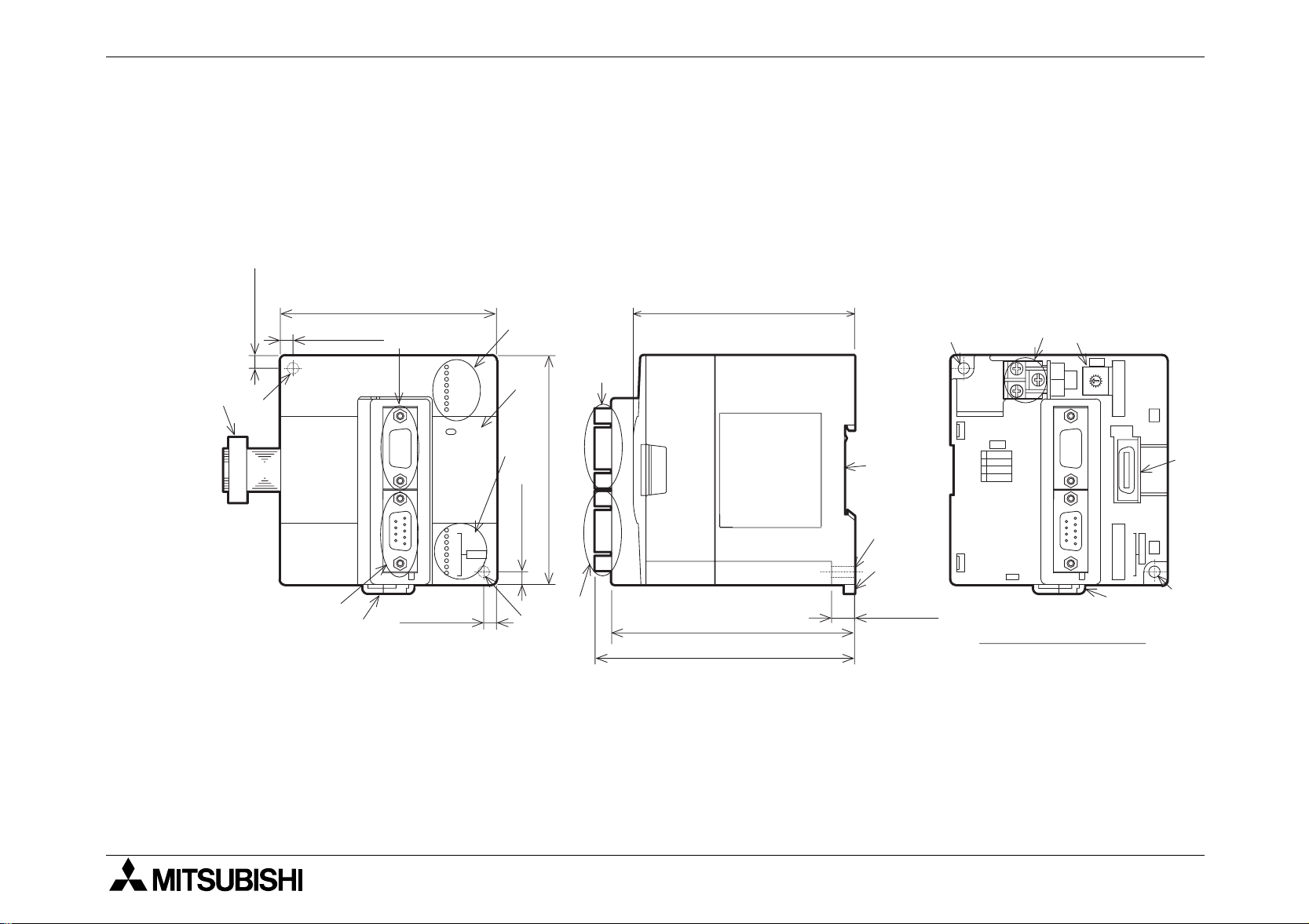
1.2 External Dimensions and Each Part Name
Dimensions: mm (inches) MASS (Weight): Approx. 0.4kg (0.88 lbs)
Accessory: Special block No. label
Figure 1.1: External Dimensions
8 5 ( 3 . 3 5 " )
5 ( 0 . 2 0 " )
5 ( 0 . 2 0 " )
a )
b )
F X 2 N - 6 4 D P - M
h )
g )
a) Extension cable
c )
R S - 2 3 2 - C
P R O F I B U S - D P
5 ( 0 . 2 0 " )
R U N
S D / R D
T O K E N
R E A D Y
F R O M / T O
P R M S E T
R S P E R R
F A U L T
P O W E R
T E S T
B 6
B 5
B 4
B 3
B 2
B 1
B 0
S T N O .
8 7 ( 3 . 4 3 " )
d )
e )
c )
f )
i )
9 0 ( 3 . 5 4 " )
b )
M O D E
0
O N L I N E 1
1
P R M S E T
2
T E S T
E
O N L I N E 2
F X 2 N - 6 4 D P - M
b )
5 ( 0 . 2 0 " )
g )
h )
b )
9 5 . 5 ( 3 . 7 6 " )
9 ( 0 . 3 5 " )
T o p c o v e r r e m o v e d
j )
k )
M O D E
2 4 +
2 4 -
F G
R U N
5
4
S D / R D
6
3
7
2
8
1
T O K E N
9
0
F
A
R E A D Y
E
B
C
D
F R O M / T O
P R M S E T
R S P E R R
F A U L T
R S - 2 3 2 - C P R O F I B U S - D P
P O W E R
l )
T E S T
B 6
S
B 5
T
B 4
B 3
N
O .
B 2
B 1
B 0
g )
b )
1 0 2 ( 4 . 0 2 " )
b) Direct mounting hole (2-
∅4.5 (0.18"))
1-2
FX2N-64DP-M Profibus-DP Master Block Introduction 1
c) RS-232C port (9-pin D-SUB Connector: #4-40unc inch screw thread)
The cable connecting between 64DP-M and personal computer is Blue ProfiCab cable.
For Blue ProfiCab, refer to MELSEC ProfiMap Configuration System for Open Networks
Software Manual.
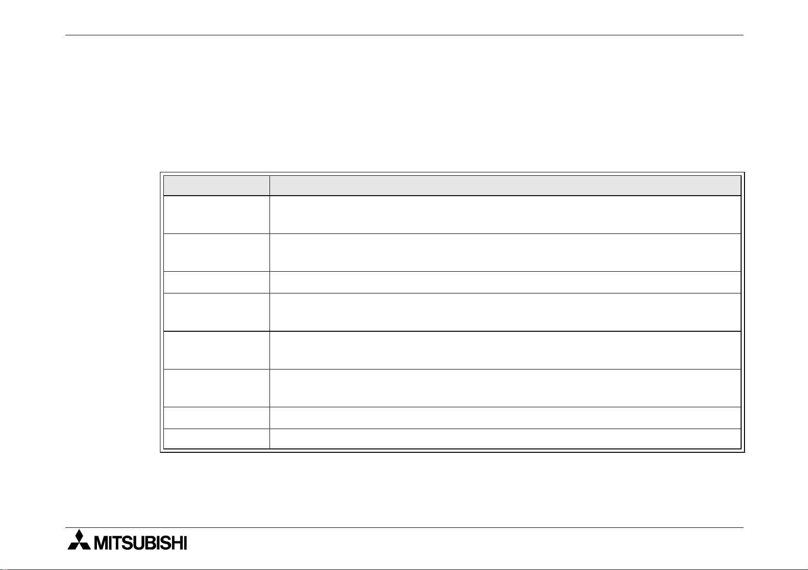
d) Status LEDs
Table 1.1: Status LEDs
LED Name Description
RUN LED
SD/RD LED
TOKEN LED ON when token is maintained.
READY LED
FROM/TO LED
PRM.SET LED
RSP ERR LED ON when a communication error occurs.
FAULT LED ON when an error occurs.
ON: During normal operation
OFF: Error
Flashes during communication with slave on the Profibus network. The
flashing interval is the time interval of the bus parameter’s Data Control Time.
ON when the Profibus-DP network subscription preparation is completed and
during subscription.
ON when a FROM/TO instruction from the programmable controller is
operating.
ON (PARAMETER SET) when in the parameter setting mode. When flashing
during operation, the parameter is not written.
e) POWER LED: ON when 24V DC power is supplied form the external power supply or
FX2N series PLC.
1-3
FX2N-64DP-M Profibus-DP Master Block Introduction 1
f) TEST LED and STATION LED
Table 1.2: TEST LED and STATION LED
LED Name Description
TEST LED ON when self-diagnosis mode is executing.
STATION
LED
Displays t he station address (Binary) during normal operation. Displays the test
type during self-diagnosis mode. (B0
~ B6)
g) Hook for mounting DIN rail
h) Profibus-DP communication port
(9-pin D-SUB Connector: #4-40unc inch screw thread)
i) Groove for mounting DIN rail (DIN 46277<DIN rail width: 35mm (1.38")>)
j) DC power supply terminals (screws terminal: M3 )
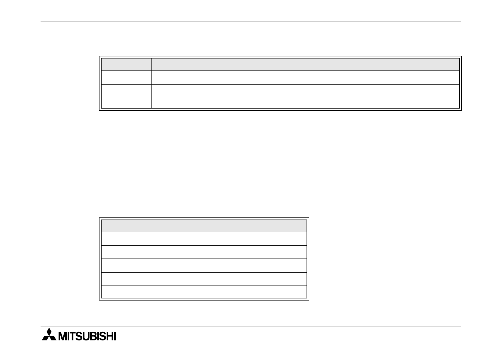
k) Mode setting switch (Default setting: “0”) For mode, refer to Chapter 4.
Table 1.3: Mode Switch
Switch No. Mode
0 ONLINE1 (Normal service mode)
1 PRM SET (Parameter setting mode)
2 TEST (Self diagnostic mode)
E ONLINE2 (Extended service mode)
~ D, F Cannot use
3
l) Extension port
1-4

FX2N-64DP-M Profibus-DP Master Block Introduction 1
1.2.1 Pin Configuration of Profibus-DP Communication Port
The connector is a 9-pin D -SUB (#4-40unc inch screw thread) type, the pin configuration is
shown below.
Figure 1.2: Pin Layout of Profibus-DP
Communication Port
Table 1.4: Profibus-DP Communication
5
4
8
3
Assigned
79
Not assigned
2
6
1
Port Pin Configuration
Pin No.
3 RXD/TXD-P Receive/transmit-Data-P
5 DGND Data Ground
6 VP Voltage-Plus
8 RXD/TXD-N Receive/transmit-Data-N
1, 2, 4,
7, 9
Signal
Meaning
Name
NC Pin not assigned
1-5

FX2N-64DP-M Profibus-DP Master Block Introduction 1
1.3 System Configuration
1.3.1 Applicable Profibus-DP Network
Note;
• The maximum number of slaves that can be connected to a 64DP-M is 60.
• Number that can be connected for 1 segment
Masters + slaves + repeaters
≤ 32 units
• Number of units that can be connected to the entire network using repeaters.
Masters + slaves
≤ 126 units
• Communications can be conducted via a maximum of 3 repeaters from an arbitrary
master or arbitrary slave to an arbitrary master or arbitrary slave. However, the whole
network can contain more than 3 repeaters. (See note above.)
1-6
 Loading...