


USER’S MANUAL
CC-Link INTERFACE BLOCK FX2N-32CCL

FX2N-32CCL CC-Link Interface Block
Foreword
• This manual contains text, diagrams and explanations which will guide the reader in the correct installation and
operation of the the FX
2N
-32CCL CC-Link Interface Block. It should be read and understood before attempting to
install or use the unit.
• Further information can be found in the FX PROGRAMMING MANUAL(ΙΙ), FX
0N
/FX2N/FX
2NC
series hardware
manuals.
• If in doubt at any stage of the installation of the FX
2N
-32CCL CC-Link Interface Block always consult a
professional electrical engineer who is qualified and trained to the local and national standards that applies to the
installation site.
• If in doubt about the operation or use of the FX
2N
-32CCL CC-Link Interface Block please consult the nearest
Mitsubishi Electric distributor.
• This manual is subject to change without notice.

FX2N-32CCL CC-Link Interface Block
i
FX2N-32CCL CC-Link INTERFACE BLOCK
USER’S MANUAL
Manual number : JY992D71801
Manual revision : C
Date : April 2003

FX2N-32CCL CC-Link Interface Block
ii
Guidelines for the safety of the user and protection of the FX
2N
-32CCL CC-Link Interface Block
This manual provides information for the installation and use of the FX
2N
-32CCL CC-Link Interface Block. The
manual has been written to be used by trained and competent personnel. The definition of such a person or
persons is as follows:
a) Any engineer who is responsible for the planning, design and construction of automatic equipment
using the product associated with this manual, should be of a competent nature, trained and qualified
to the local and national standards required to fulfill that role. These engineers should be fully aware of
all aspects of safety with regards to automated equipment.
b) Any commissioning or service engineer must be of a competent nature, trained and qualified to the
local and national standards required to fulfill that job. These engineers should also be trained in the
use and maintenance of the completed product. This includes being completely familiar with all
associated documentation for said product. All maintenance should be carried out in accordance with
established safety practices.
c) All operators of the completed equipment (see Note) should be trained to use this product in a safe
manner in compliance to established safety practices. The operators should also be familiar with
documentation which is associated with the actual operation of the completed equipment.
Note : The term ‘completed equipment’ refers to a third party constructed device which contains or uses the
product associated with this manual.
Notes on the Symbols Used in this Manual
At various times throughout this manual certain symbols will be used to highlight points which are intended to
ensure the users personal safety and protect the integrity of equipment. Whenever any of the following
symbols are encountered its associated note must be read and understood. Each of the symbols used will
now be listed with a brief description of its meaning.
FX2N-32CCL CC-Link Interface Block
iii
Hardware warnings
Software warnings
1 ) Indicates that the identified danger
WILL
cause physical and property damage.
2 ) Indicates that the identified danger
POSSIBLY
cause physical and property damage.
3 ) Indicates a point of further interest or further explanation.
1 ) Indicates special care must be taken when using this element of software.
2 ) Indicates a special point of which the user of the associate software element should be aware.
3 ) Indicates a point of interest or further explanation.

FX2N-32CCL CC-Link Interface Block
iv
• Under no circumstances will Mitsubishi Electric be liable responsible for any consequential damage
that may arise as a result of the installation or use of this equipment.
• All examples and diagrams shown in this manual are intended only as an aid to understanding the
text, not to guarantee operation. Mitsubishi Electric will accept no responsibility for actual use of the
product based on these illustrative examples.
• Please contact a Mitsubishi Electric distributor for more information concerning applications in life
critical situations or high reliability.

FX2N-32CCL CC-Link Interface Block Contents
v
CONTENTS
1. Introduction .................................. ... .. ................... ... .. ................... .. ............1-1
1.1 Outline of product ......................................................................................................1-1
1.2 Connection to CC-Link ..............................................................................................1-3
1.3 System configuration of entire CC-Link .....................................................................1-4
2. Product Specifications ...............................................................................2-1
2.1 Outside dimensions and nomenclature .....................................................................2-2
2.2 General specifications and performance specifications ............................................2-3
3. Connection and Wiring ..............................................................................3-1
3.1 Connection to PC ......................................................................................................3-1
3.2 Wiring of power supply ..............................................................................................3-2
3.3 Wiring of CC-Link ......................................................................................................3-3
4. Setting of Remote Device Stations ............................................................4-1
4.1 Setting of station Nos., number of stations and transmission speed .........................4-1
4.2 List of number of remote points and remote Nos. .....................................................4-3
5. Assignment of Buffer Memory (BFM) .........................................................5-1
5.1 Outline of data communication ..................................................................................5-1
5.2 BFM dedicated to read ................................................................... .......... ......... ........5-2
5.3 BFM dedicated to write ..............................................................................................5-8
5.4 System area of remote I/O ......................................................................................5-12
5.5 Contents of errors ....................................................................................................5-14
6. Programming Examples ............................................................................6-1
6.1 System configuration .................................................................................................6-1
6.2 Flow of communication data ......................................................................................6-3

FX2N-32CCL CC-Link Interface Block
Contents
vi
6.3 Program in master PC ...............................................................................................6-5
6.4 Program in FX PC ...................................................................................................6-11

FX2N-32CCL CC-Link Interface Block Introduction 1
1-1
1. Introduction
The CC-Link interface block FX2N-32CCL is an interface block which connects the FX0N/FX2N/FX
2NC
PC to
the CC-Link.
1.1 Outline of product
Applicable PC
The FX
2N
-32CCL can be connected as a special extension block of the FX0N/FX2N/FX
2NC
Series micro PC.
Control instruction
The buffer memory of the FX
2N
-32CCL is read and written by FROM/TO instructions.
Connection to CC-Link
The FX
2N
-32CCL is connected as a remote device station to the CC-Link system.
Shielded twisted pair cables are used for wiring.
Number of I/O points
Eight I/O points (including input and output) are occupied in the FX PC.
However, the capacity of the 5 V DC power supplied from the PC is limited.
The current consumption of 5 V DC in the FX
2N
-32CCL is 130 mA. Make sure that the total current consump-
tion of 5 V DC including other special blocks does not exceed the criteria.
Station No. and number of stations
Station No. : 1 to 64 (rotary switch)
Number of stations: 1 to 4 (rotary switch)
FX2N-32CCL CC-Link Interface Block Introduction 1
1-2
Transmission speed
Transmission distance
10 Mbps : 100 m
5 Mbps : 150 m
2.5 Mbps : 200 m
625 kbps : 600 m
156 kbps : 1,200 m
Detailed specifications conform to the CC-Link system common specifications.
Number of remote points
The number of remote I/O points in one station is 32 input points and 32 output points . However, the upper 16
points of the final station are occupied by the CC-Link system as the system area.
The number of remote registers in one station is 4 points of RW write area and 4 points of RW read area.
Because the number of stations can be selected within the range of 1 to 4, the system can be constructed in
accordance with the control size.
FX2N-32CCL CC-Link Interface Block Introduction 1
1-3
1.2 Connection to CC-Link
The FX PC connected with the inter face block FX2N-32CCL functions as a remote device station in the CCLink system.
One to four FX
2N
-32CCL units can be used at a time, and station Nos. not assigned to these FX2N-32CCL
units should be assigned to other remote device stations, remote I/O stations and local stations.
The number of connectable units, the transmission speed, the transmission distance, etc. conform to the CCLink system common specifications.
Terminal resistor
Terminal resistor
Shielded twisted pair cable
Remote device station
FX
0N
/FX2N/FX
2NC
Series
PC + FX
2N
-32CCL
Remote device station
FX
0N
/FX2N/FX
2NC
Series
PC + FX
2N
-32CCL
Remote I/O station Remote device station
CC-Link master station
Local station

FX2N-32CCL CC-Link Interface Block Introduction 1
1-4
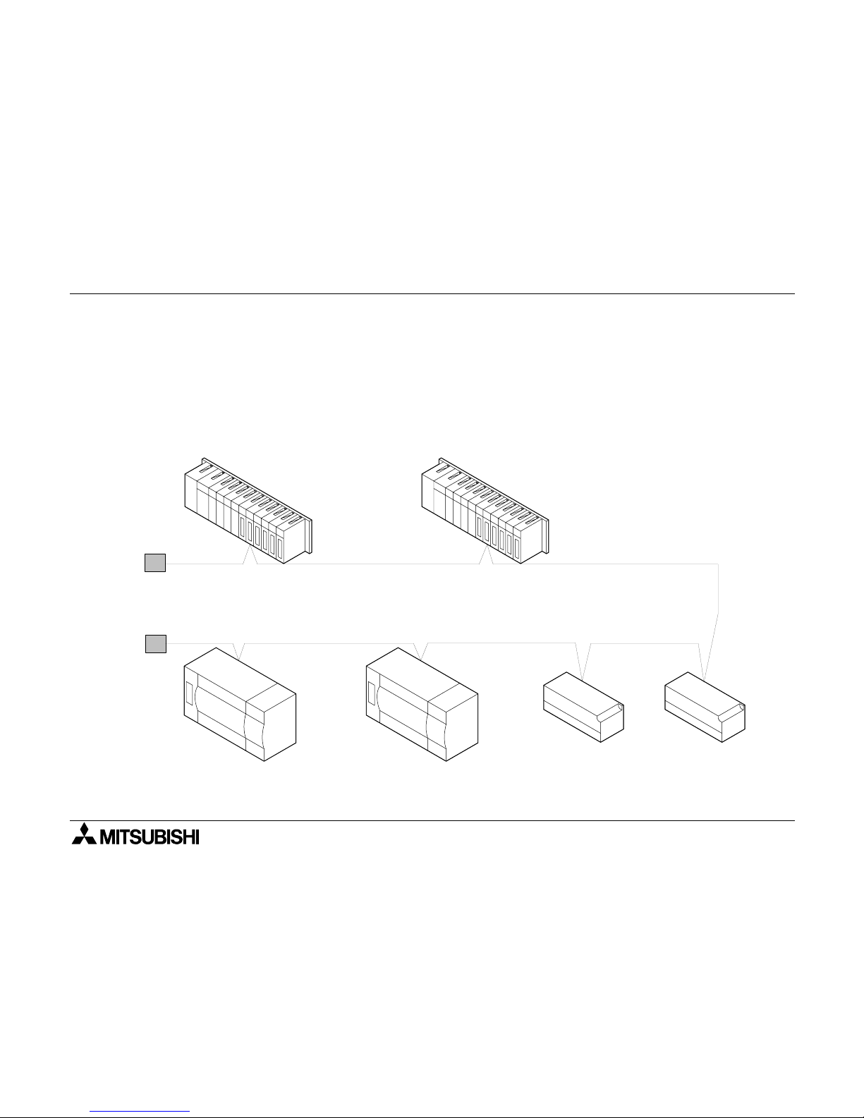
1.3 System configuration of entire CC-Link
The figure below shows the system configuration of the entire CC-Link.
For the details, refer to the user manual of the master unit in the CC-Link system.
RS-232C
interface unit
AJ65BT-R2
Remote I/O unit
AJ65BTB
AJ65BTC
Analog-digital
converter unit
AJ65BT-64AD
Local station
A1SJ61BT11
AJ61BT11
Local station
A1SJ61BT11
AJ61BT11
Master station
Shielded twisted pair cable
Terminal resistor (essential)
Terminal resistor (essential)
Shielded twisted pair cable
Intelligent device
station
Remote device station
Remote I/O station
Up to 64 units
Up to 26 units
Up to 26 units
Up to 42 units
64 units in all
A1SJ61QBT11
AJ61QBT11
FX PC
FX
0N
/FX2N/FX
2NC
Series
+ FX
2N
-32CCL
FX2N-32CCL CC-Link Interface Block Specifications 2
2-1
2. Product Specifications
Cautions on design
• For the status of each station in the case in which the PC CPU stops its operation or communication error has occurred in the data link, read thoroughly the contents of "5.
Data Link Processing Time" of the user manual of the master unit.
Construct an interlock circuit in a PC program so that the system can operate conservativ ely using
the communication status information (SB, SW).
If the interlock circuit is not correctly constructed, wrong output or malfunction may occur, and an
accident may occur at the end.
- Receive data from the master station or a local station in which a data link error has occurred
1 ) Remote input (RX), remote output (RY)
The data varies depending on setting of the condition set switch on the unit and setting of the
input data (SW4) in a station in which a data link error has occurred.OFF: Data is cleared (All
OFF).
ON: The data just before an error occurred is held.
2 ) Remote register (RWw, RWr), remote input (RX), remote output (RY)
The data just before an error occurred is held without regard to setting of the SW4.
• Never bind the communication cable together with the main circuit, the power cable, etc. Never
locate the communication cable near the main circuit, the power cable, etc.
Keep the communication cable by 100 mm or more from the main circuit, the power cable, etc. If
this distance is not kept, malfunction may occur due to noise.
FX2N-32CCL CC-Link Interface Block Specifications 2
2-2
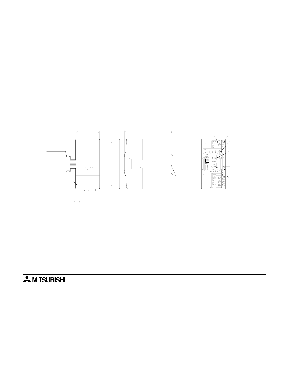
2.1 Outside dimensions and nomenclature
Outer paint color: Munsell 0.08GY/7.64/0.81 Weight: Approx.200 g
Accessories: Special block No. label.
POWER LED : Lit when 5 VDC power is supplied from the PC main unit.
L RUN LED : Lit while communication is performed correctly.
L ERR LED : Lit when a communication error has occurred.
Lit when a rotary switch is incorrectly set. Flickers when setting of a rotary switch is changed
while the power is turned on.
RD LED : Lit while data is received.
SD LED : Lit while data is sent.
Extension
cable
2-
φ
4.5(0.18)
Mounting
hole
DIN rail
35mm(1.38)
mounting
bezel
M3(0.12)
terminal screw
External 24 VDC
ground terminal
Station No.
set switch
Number of
occupied
stations
set switch
Next step
extension
connector
Baud rate
set switch
4(0.16)
43(1.69)
90(3.54)
87(3.42)
80(3.15)
POWER
FX2N-32CCL
LRUN LERR RD SD
(inches)
[Front face of top cover] [Side] [Inside of top cover]
FX2N-32CCL CC-Link Interface Block Specifications 2
2-3
2.2 General specifications and performance specifications
General specifications
Dielectric strength:500 VAC for 1 min (between external terminals as a whole and ground terminal) Other
specifications are equivalent to those of the PC basic unit.
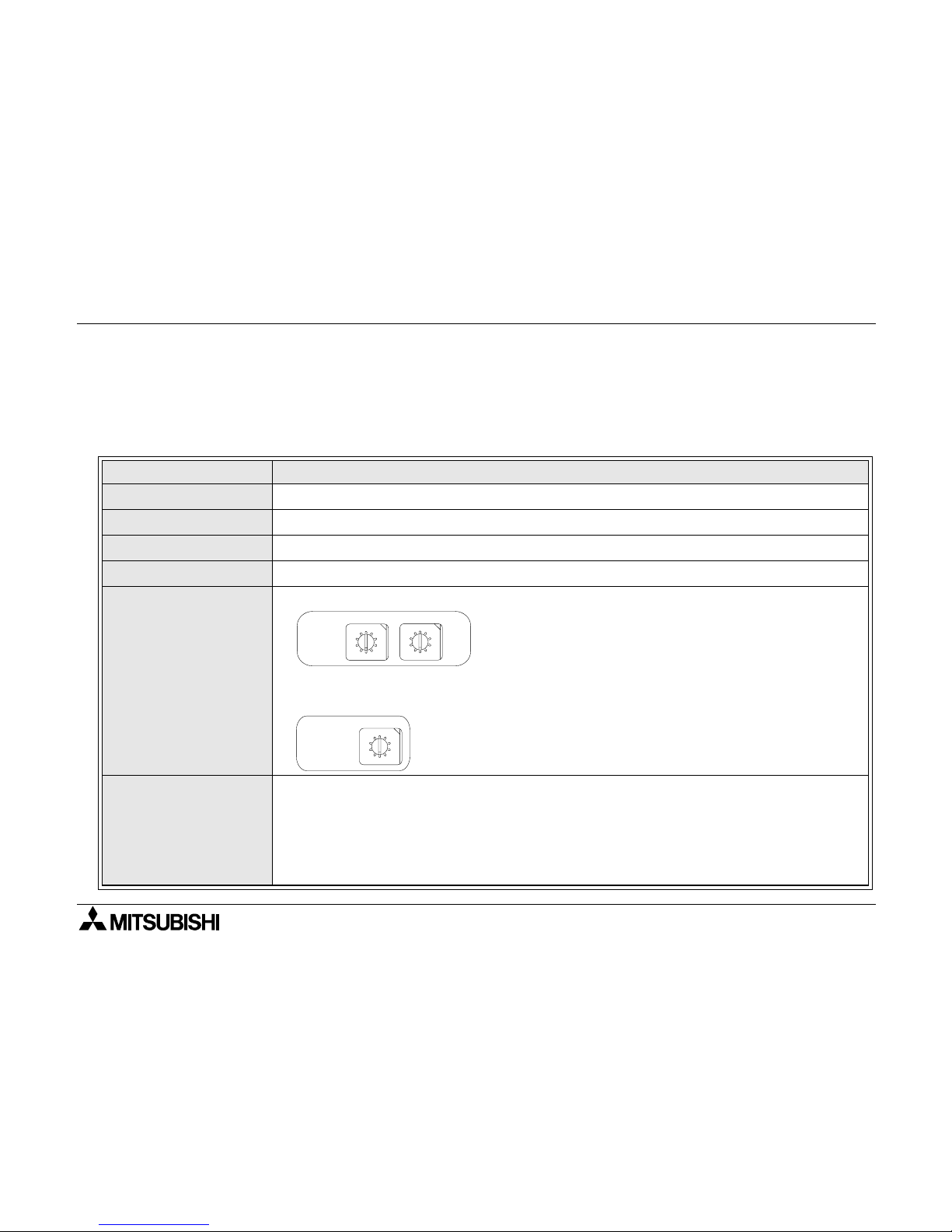
Performance specifications
Item Specifications of FX2N-32CCL
Drive power supply
24 VDC+/-10%, 50 mA (supplied from external terminal)
Control power supply
5 VDC, 130 mA (supplied from PC via extension cable)
Insulation method
Network bus and internal power supply are insulated each other by photocoupler.
Station type
Remote device station
Station No.
Number of stations
Station No.: 1 to 64 (set by rotary switch)
Number of remote
device points
Number of remote
register points
The number of remote I/O points in one sta tion is 3 2 input points and 32 outp ut point s.
However, the upper 16 points are occupied by the CC-Link system as the system area.
The number of remote registe r points in on e station is 4 poin ts of RW write area an d 4
points of RW read area.
For the details of the number of rem ote poi nts an d the remote Nos. in a ccordanc e with
setting of the number of stations, refer to "4.2 List of number of remote points a nd
remote Nos."
0
5
1
2
3
4
9
8
7
6
STATION
No.
✕
10
✕
1
10's digit
0
5
1
2
3
4
9
8
7
6
1's digit
OCCUPY
STATION
0
5
1
2
3
4
9
8
7
6
0, 65 to 99: Setting error
0: 1 station 1: 2 stations
2: 3 stations 3: 4 stations
4 to 9: Not available
Number of stations: 1 to 4 (set by rotary switch)

FX2N-32CCL CC-Link Interface Block Specifications 2
2-4
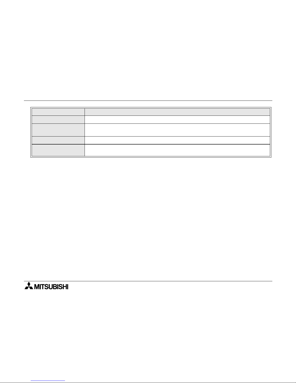
Transmission speed
156 kbps, 625 kbps, 2.5 Mbps, 5 Mbps, 10 Mbps (set by rotary switch)
Maximum
transmission distance
It varies depending on the transmission speed.
1 )The cable length between the master/local station and an adjacent station should be
2 m or more without regard to setting of the transmission speed.
2 )When the transmission speed is 5 Mbps or 10 Mbps, the maximum transmission dis-
tance varies depending on the cable length between remote I/O stations and remote
device stations.
Item Specifications of FX2N-32CCL
B RATE
0
5
1
2
3
4
9
8
7
6
0: 156 kbps 1: 625 kbps 2: 2.5 Mbps
3: 5 Mbps 4: 10 Mbps 5 to 9: Setting error
Master station
R e m ote I/ O
station
Remote
device station
Local station Local station
R e m ote I/ O
station
Remote
device station
R e m ote I/ O
station
Remote
device station
Maximum transmission distance
①②①②
R e m ote I/ O
station
Remote
device station
①
FX PC functi ons as a remote de vice s tation.
T r ansmission
speed
•••• ‚‚‚‚
Maximum transmission
distance
156kbps
2 m or more
30 cm or more 1200 m
625kbps
30 cm or more 600 m
2.5Mbps
30 cm or more 200 m
5Mbps
60 cm or more 150 m
30 to 59 cm 110 m
10Mbps
1 m or more 100 m
60 to 99 cm 80 m
30 to 59 cm 50 m
FX2N-32CCL CC-Link Interface Block Specifications 2
2-5
Operation indication
LEDs (POWER, L RUN, L ERR, RD, SD)
Number of occupied
I/O points
Eight I/O points (including input and output) of FX PC
Applicable PC
FX
0N
, FX2N, FX
2NC
Series PC
Communication with
PC
Communication is performed from the FX PC via the buffer memory using FROM/TO
instructions.
Item Specifications of FX2N-32CCL
 Loading...