


FX2N-1HC SPECIAL FUNCTION BLOCK
USER’S GUIDE
JY992D65401C
This manual contains text, diagrams and explanations which will guide the reader in the correct installation
and operation of the FX
to install or use the unit.
Further information can be found in the FX PROGRAMMING MANUAL and FX
MANUAL.
1. INTRODUCTION
-1HC special function block and should be read and understood before attempting
2N
SERIES HARDWARE
2N
• The hardware high-speed counter block is a 2-phase 50 kHz high-speed counter. It is a special function
block for the FX
2N
2NC
, FX
series PLC. The FX2N-1HC counts at a higher speed than the built-in highspeed counter of the PLC (2-phase 30 kHz, 1-phase 60 kHz) and performs comparisons and outputs
directly.
• Various counter modes, such as 1-phase or 2-phase, 16-bit or 32-bit modes, can be selected using
commands from the PLC. Allow the FX
-1HC unit to run only after setting these mode parameters.
2N
• The source of your input signal should be a 1 or 2 phase encoder. A 5V, 12V, or 24V power source can
be used. An initial value setting command input (PRESET) and a count prohibit command input (DISABLE) are also available.
• The FX
-1HC has two outputs. When the counter value coincides with an output compare value, the
2N
appropriate output is set ON. The output transistors are individually isolated to allow either sink or
source connection methods.
• Data transfer between the FX
buffer memories (each of 16 bits) in the FX
• The FX
-1HC occupies 8 points of I/O on the FX2N, FX
2N
-1HC and the FX2N PLC is by buffer memory exchange. There are 32
2N
2N
-1HC.
2NC
expansion bus. The 8 points can be allo-
cated from either inputs or outputs.
1.1 External dimensions
Mass (weight): Approx. 0.3 kg (0.66 lbs) Dimensions: mm (inches)
Accessories: Self-adhesive labels special block number identification.
A12+
A -
B12+
B -
XD5
COMD
COMP
YH-
YS-
A24+
A5+
B24+
B5+
XD24
XP24
YH+XP5
YS+
55(2.17)
8
FX2N-1HC
11
9
B12+
A12+
A -
A24+
A5+
B24+
55(2.17)
POWER
UP
DOWN
A
ø
øB
DIS
PRE
YH
YS
3
4
5
6
7
11
12
13
14
15
87(3.43)
4(0.16)
2
1
17
90(3.54)
80(3.15)
16
1
Mounting hole 2-φ4.5 (0.18)
2
Extension cable and connector
3
UP LED
4
DN (Down) LED
5
A LED
φ
6
B LED
φ
7
POWER LED
8
A, φB terminal (M3 (0.12) screws)
φ
9
PRESET terminal (M3 (0.12) screws)
<Using the solderless termination>
6.2mm
(0.24 inches)
or less
6.2mm
(0.24 inches)
or less
FOR M3
(0.12 inches)
(0.16)
4
10
YHxYS terminal (M3 (0.12) screws)
11
DISABLE terminal (M3 (0.12) screws)
12
DIS (DISABLE) LED
13
PRESET LED
14
YH LED
15
YS LED
16
DIN rail clip
17
Attachment groove for 35 (1.38) wide DIN rail
10
• Use crimp terminals of the dimensions specified in the left figure.
• Secure the terminals using a tightening torque of 0.5 to 0.8 Nxm
(5 to 8 kgxcm).
• Wire only to the module terminals discussed in this manual.
Leave all others vacant.
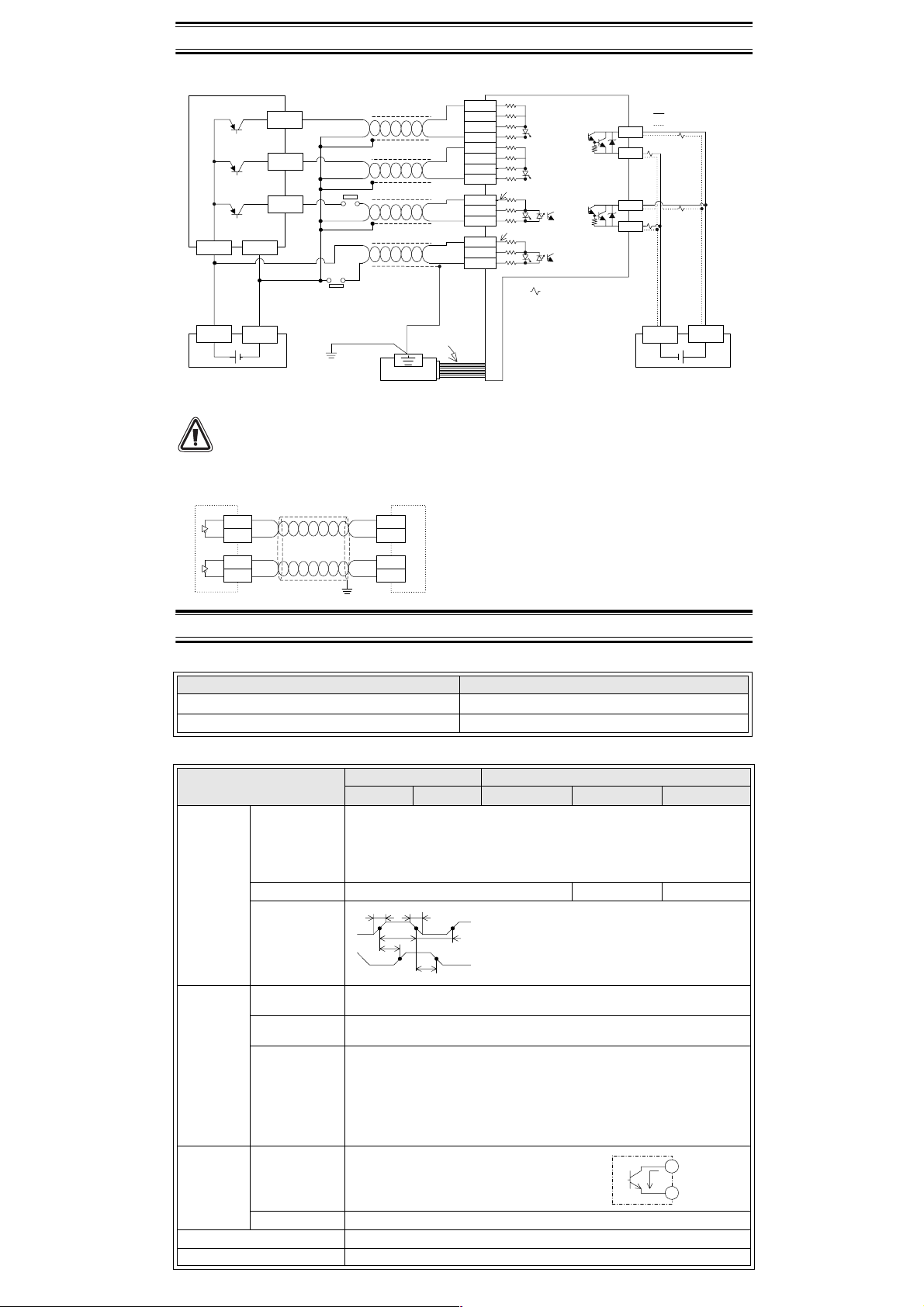
2. WIRING
PNP output encoders
PNP output encoders
Phase A
Phase B
Phase Z
+24V
External power source
DC5V,12V,24V
OUT
OUT
OUT
COM+24V
0 V
ØA
ØB
PRESET
DISABLE
START
Class 3
grounding
:
(<100 )
Shielding Wire
Shielding Wire
Shielding Wire
Shielding Wire
*2
PLC
Extension
cable
3.3k
A24+
A12+
A5 +
A B24+
B12+
B5 +
B -
XP24
XP 5
COMP
XD24
XD 5
COMD
FX2N-1HC
1.5k
0.27k
0.1k
12 to 24V inputtable
1.5k
0.5k
0.2k
12 to 24V
inputtaable
*1. " " is an external load
connected with the out put.
*2. Connect the grounded terminal
at the PLC side as required.
2.2kW
2.2kW
:source
:sink
YH+
YH-
YS+
YS-
Power supply for out put
load drive DC5 to 24V
*1
*1
*1
*1
+24V
0 V
If using on NPN output encoder please take care to match the polarity of the terminals of the
encoder to those of the FX
2N
-1HC.
Line driver output encoders
Line driver output encoders
LA
LAR
LB
LBR
Shielding Wire
FX2N-1HC
A5+
A -
B5+
B -
3. SPECIFICATIONS
3.1 Environmental specifications
Item Specification
Environmental specifications (excluding following)
Same as those for the FX
Dielectric withstand voltage 500V AC, 1min (between all terminals and ground)
3.2 Performance specifications
Item
Signal level
Input signal
MAX. frequency 50 kHz 25 kHz 12.5kHz
Pulse shape
Format
Range
Counting
specification
Comparison
Ty p e
Output
signal
Types of
outputs
Output capacity 5V to 24V DC 0.5A
I/O occupation 8 points taken from the FX
Power from base 5V DC 90mA(Internal power supply from main unit or powered extension unit)
1-phase input 2-phase input
1 input 2 inputs 1 edge count 2 edge count 4 edge count
Phase A, Phase B [A24+],[B24+] :24V DC±10% 7mA or less
PRESET,DISABLE [XP24],[XD24] :10.8V to 26.4V DC 15mA or less
(Selected by terminal connection)
t1 t1
t2
t3
Automatic UP/DOWN (however, when on 1-phase 1-input mode, UP/DOWN is
determined by a PLC command or an input terminal.)
When 32-bit is specified : -2,147,483,648 to +2,147,483,647
When 16-bit is specified : 0 to 65,535 (upper limit can be user specified)
Each output is set when the present value of the counter matches with the
compare value (which is transferred from the PLC), and is switched OFF by a
reset command from the PLC.
YH : Direct output processed by hardware.
YS : Software processed output with worst delay time of 300µs.
(Therefore, when the input frequency is 50 kHz, there is a worst case delay of
15 input pulses.)
YH +:transistor output for YH output
YH −:transistor output for YH output
YS +:transistor output for YS output
YS −:transistor output for YS output
[A12+],[B12+] :12V DC±10% 7mA or less
[A5+],[B5+] :3.5V to 5.5V DC 10.5mA or less
[XP5],[XD5] :5V DC±10% 8mA or less
t1 :Rise/fall time is 3ms or less
t2 :ON/OFF pulse duration 10µs or more
t3 :Phase difference between phase A and
t2
t3
phase B is 3.5ms or more
PRESET(Z phase) input 100µs or more
DISABLE (count prohibit) input 100ms or more
2N
expansion bus (can be either inputs or outputs)
main unit
2N
NPN
YH+
YS+
YHYS-
 Loading...