

Page 1

C
MIT
SUBIS
C
HI ELECTRI
MELSEC FX Series
Programmable Logic Controllers
User's Manual
Art. no.: 138030
15 04 2003
JY992D93401
Version D
FX2N-10PG
MITSUBISHI ELECTRI
INDUSTRIAL AUTOMATION
Page 2

Model FX2N-10PG Pulse Output Block
Foreword
• This manual contains text, diagrams and explanations which will guide the reader in the
correct installation and operation of the FX
and understood before attempting to install or use the unit.
-10PG Pulse Output Block. It should be read
2N
• Further information can be found in the FX
Series HARDWARE MANUAL, FX
2N
2NC
HARDWARE MANUAL and THE FX SERIES OF PROGRAMMABLE CONTROLLER
PROGRAMMING MANUAL ΙΙ.
• If in doubt at any stage of the installation of FX
-10PG Pulse Output Block always consult
2N
a professional electrical engineer who is qualified and trained to the local and national
standards which apply to the installation site.
• If in doubt about the operation or use of FX
-10PG Pulse Output Block please consult the
2N
nearest Mitsubishi Electric distributor.
• This manual is subject to change without notice.
Series
Page 3

Model FX2N-10PG Pulse Output Block
Model FX
2N
-10PG Pulse Output Block
USER’S MANUAL
Manual number : JY992D93401
Manual revision : D
Date : April 2003
i
Page 4

Model FX2N-10PG Pulse Output Block
ii
Page 5

Model FX2N-10PG Pulse Output Block
FAX BACK
Mitsubishi has a world wide reputation for its efforts in continually developing and pushing back
the frontiers of industrial automation. What is sometimes overlooked by the user is the care
and attention to detail that is taken with the documentation. However, to continue this process
of improvement, the comments of the Mitsubishi users are always welcomed. This page has
been designed for you, the reader, to fill in your comments and fax them back to us. We look
forward to hearing from you.
Fax numbers: Your name: ...................................................
Mitsubishi Electric.... .....................................................................
America (01) 847-478-2253 Your company: .............................................
Australia (02) 638-7072 .....................................................................
Germany (0 21 02) 4 86-1 12 Your location:................................................
Spain (34) 93-589-1579 .....................................................................
United Kingdom (01707) 278-695
Please tick the box of your choice
!
!
!
!
!
!
Good
Ye s
Tidy
Ye s
Ye s
Good
What condition did the manual arrive in?
Will you be using a folder to store the manual?
What do you think to the manual presentation?
Are the explanations understandable?
Which explanation was most difficult to understand: ..................................................................
....................................................................................................................................................
Are there any diagrams which are not clear?
If so,which: ..................................................................................................................................
What do you think to the manual layout?
If there one thing you would like to see improved, what is it? .....................................................
....................................................................................................................................................
....................................................................................................................................................
Could you find the information you required easily using the index and/or the contents, if
possible please identify your experience: ...................................................................................
....................................................................................................................................................
....................................................................................................................................................
....................................................................................................................................................
....................................................................................................................................................
!
Minor damage
!
No
!
Unfriendly
!
Not too bad
!
No
!
Not too bad
!
Unusable
!
Unusable
!
Unhelpful
Do you have any comments in general about the Mitsubishi manuals? .....................................
....................................................................................................................................................
....................................................................................................................................................
....................................................................................................................................................
....................................................................................................................................................
Thank you for taking the time to fill out this questionnaire. We hope you found both the product
and this manual easy to use.
iii
Page 6

Model FX2N-10PG Pulse Output Block
iv
Page 7

Model FX2N-10PG Pulse Output Block
Guidelines for the Safety of the User and Protection of the FX2N-10PG Pulse
Output Block
This manual provides information for the use of the FX2N-10PG Pulse Output Block. The
manual has been written to be used by trained and competent personnel. The definition of
such a person or persons is as follows;
a) Any engineer who is responsible for the planning, design and construction of automatic
equipment using the product associated with this manual should be of a competent
nature, trained and qualified to the local and national standards required to fulfill that
role. These engineers should be fully aware of all aspects of safety with regards to
automated equipment.
b) Any commissioning or service engineer must be of a competent nature, trained and
qualified to the local and national standards required to fulfill that job. These engineers
should also be trained in the use and maintenance of the completed product. This
includes being completely familiar with all associated documentation for the said product.
All maintenance should be carried out in accordance with established safety practices.
c) All operators of the completed equipment (see Note) should be trained to use this
product in a safe manner in compliance to established safety practices. The operators
should also be familiar with documentation which is associated with the operation of the
completed equipment.
Note :
Note: the term ‘completed equipment’ refers to a third party constructed device which
contains or uses the product associated with this manual.
Notes on the Symbols Used in this Manual
At various times throughout this manual certain symbols will be used to highlight points of
information which are intended to ensure the users personal safety and protect the integrity of
equipment. Whenever any of the following symbols are encountered its associated note must
be read and understood. Each of the symbols used will now be listed with a brief description of
its meaning.
Hardware Warnings
1) Indicates that the identified danger
2) Indicates that the identified danger could
WILL
cause physical and property damage.
POSSIBLY
cause physical and property
damage.
3) Indicates a point of further interest or further explanation.
Software Warnings
4) Indicates special care must be taken when using this element of software.
5) Indicates a special point which the user of the associate software element should
be aware of.
6) Indicates a point of interest or further explanation.
v
Page 8

Model FX2N-10PG Pulse Output Block
• Under no circumstances will Mitsubishi Electric be liable or responsible for any
consequential damage that may arise as a result of the installation or use of this equipment.
• All examples and diagrams shown in this manual are intended only as an aid to
understanding the text, not to guarantee operation. Mitsubishi Electric will accept no
responsibility for actual use of the product based on these illustrative examples.
• Please contact a Mitsubishi Electric distributor for more information concerning applications
in life critical situations or high reliability.
Trademark registration
The company names and product names described in this manual are the registered names
and trademarks of the relevant companies.
vi
Page 9

Model FX2N-10PG Pulse Output Block
Associated Manuals
This manual describes the handling and operation of MELSEC-FX Series FX
-10PG Pulse
2N
Output Block. For the configuration and commands of the system, also refer to the manuals of
the following PLC. Before operation, read this manual and the manuals of the PLC thoroughly
and be sure you sufficiently understand their specifications for proper operation.
Also, be sure that the manual is provided to the end user.
Manual name Manual No. Description
2N
-10PG
FX
USER'S MANUAL
(this manual)
2N
FX
-10PG
Installation Manual
(in same package)
2N
FX
HARDWARE MANUAL
(in same package)
2N
c (D/UL)
FX
HARDWARE MANUAL
(in same package)
2N
FX
c (DSS/DS)
HARDWARE MANUAL
(in same package)
THE FX SERIES OF
PROGRAMMABLE
CONTROLLER
PROGRAMMING
MANUAL
ΙΙ
JY992D93401
JY992D91901
JY992D66301
JY992D87201
JY992D76401
JY992D88101
The manual explains the details of the hardware regarding the
specifications, wiring, installation, etc. of the FX
2N
-10PG
Series PLC.
The manual explains the specifications, installation, etc. of the
2N
FX
-10PG Pulse Output Block.
The manual explains the details of the hardware regarding the
specifications, wiring, installation, etc. of the FX2N Series
PLC.
The manual explains the details of the hardware regarding the
specifications, wiring, installation, etc. of the FX
2NC
(D/UL)
Series PLC.
The manual explains the details of the hardware regarding the
specifications, wiring, installation, etc. of the FX
2NC
(DSS/DS)
Series PLC.
The manual explains the commands of FX
2N
and FX
2NC
Series.
Of the manuals listed above, THE FX SERIES OF PROGRAMMABLE CONTROLLER
PROGRAMMING MANUAL ΙΙ are not packed with the product.
If necessary, contact your dealer to request the desired manual.
FX
-10PG Installation Manual, FX2N Handy Manual and FX
2N
Handy Manual are packed
2NC
with each product.
vii
Page 10

Model FX2N-10PG Pulse Output Block
viii
Page 11

Model FX2N-10PG Pulse Output Block Contents
1. Introduction .........................................................................................1-1
1.1 Product outline.................................................................................................1-1
2. Outside dimensions and component names.......................................2-1
2.1 Outside d ime n s io n s .............. .. ............. .. ............. ... .. ............. .. .............. .. .. .......2-1
2.2 LED display......................................................................................................2-2
2.3 Pin layout and assignment...............................................................................2-3
2.3.1 Applicable connector and cable size...................................... ...... ....... ................2-4
3. Installation........................................................................................... 3-1
3.1 DIN rail installation...........................................................................................3-1
3.2 Direct installation..............................................................................................3-1
4. System configuration.................................................... ............ ...........4-1
4.1 Connection with PLC ....................................................................................... 4-1
4.2 Applicable PLC ................................................................................................4-2
5. Specifications......................................................................................5-1
5.1 Environmental specifications ...........................................................................5-1
5.2 Power supply specifications.............................................................................5-1
5.3 Performance specifications..............................................................................5-1
5.4 Input specifications..........................................................................................5-2
5.5 Output specifications........................................................................................5-2
6. Wiring..................................................................................................6-1
6.1 Input output circuit............................................................................................6-1
6.2 Input wiring.......................................................................................................6-4
6.2.1 START, DOG, X0, X1, S/S.............. ....... ...... ....................................... ...... ....... ...6-4
6.2.2 A-phase +, A-phase -, B-phase +, B-phase - ......................................................6-5
6.2.3 PGO+, PGO-.......................................................................................................6-6
6.3 Output wiring....................................................................................................6-7
6.3.1 VIN+, VIN-, FP+, FP-, RP+, RP- .........................................................................6-7
6.3.2 CLR+, CLR-.........................................................................................................6-8
6.4 Connection with stepping motor.......................................................................6-9
6.5 Connection with Model MR-C Servo Motor....................................................6-10
6.6 Connection with Model MR-J Servo Motor ....................................................6-11
6.7 Connection with Model MR-J2 (-Jr, -Super) Serv o Motor..............................6-12
6.8 Connection with Model MR-H Servo Motor....................................................6-13
7. Buffer memory (BFM)..........................................................................7-1
7.1 BFM list............................................................................................................ 7-1
7.2 Details o f BF M ................. .. .............. .. .. ............. .. .............. .. ............. .. ... ...........7-5
7.2.1 BFM#1, #0 Maximum speed ..............................................................................7-5
7.2.2 BFM#2 Bias speed.............................................................................................7-5
7.2.3 BFM#4, #3 Jog speed........................................................................................7-5
7.2.4 BFM#6, #5 Zero return speed (high speed) ....................................................... 7-5
7.2.5 BFM#7 Zero return speed (creep).......................................................................7-5
7.2.6 BFM#8 Zero-point signal number........................................................................7-5
7.2.7 BFM#10, #9 Zero-point address........................................................................7-6
7.2.8 BFM#11 Acceleration time.................................................................................7-6
7.2.9 BFM#12 Deceleration time.................................................................................7-6
7.2.10 BFM#14, #13 Target address I...........................................................................7-6
7.2.11 BFM#16, #15 Operation speed I........................................................................7-6
7.2.12 BFM#18, #17 Target address II.........................................................................7-7
7.2.13 BFM#20, #19 Operation speed II.....................................................................7-7
7.2.14 BFM#21 Override setting ................................................................................... 7-7
7.2.15 BFM#23, #22 Operation speed current value ....................................................7-7
7.2.16 BFM#25, #24 Current address...........................................................................7-7
7.2.17 BFM#26 Operation commands .......................................................................... 7-8
ix
Page 12

Model FX2N-10PG Pulse Output Block Contents
7.2.18 BFM#27 Operation pattern...............................................................................7-11
7.2.19 BFM#28 Status information..............................................................................7-13
7.2.20 BFM#29 m code..............................................................................................7-13
7.2.21 BFM#30 Machine model code..........................................................................7-13
7.2.22 BFM#33, #32 pulse rate...................................................................................7-14
7.2.23 BFM#35, #34 Feed rate ...................................................................................7-14
7.2.24 BFM#36 Parameters ........................................................................................7-14
7.2.25 BFM#37 Error code..........................................................................................7-19
7.2.26 BFM#38 Terminal information..........................................................................7-19
7.2.27 BFM#40, #39 Current address........................................................................7-19
7.2.28 BFM#42, #41 Manual pulse generator input current value ..............................7-19
7.2.29 BFM#44, #43 Manual pulse generator input frequency ...................................7-20
7.2.30 BFM#45 Manual pulse generator input electronic gearing (numerator)...........7-20
7.2.31 BFM#46 Manual pulse generator input electronic gearing (denominator) .......7-20
7.2.32 BFM#47 Input response of manual pulse generator ........................................7-20
7.2.33 BFM#64 Version information............................................................................7-20
7.2.34 BFM#98 Table start No. ...................................................................................7-20
7.2.35 BFM#99 Executing table No.............................................................................7-20
7.2.36 BFM#100 and later BFM for program with table system.................................7-20
8. Operation pattern................................................................................8-1
8.1 General items for positioning operation...........................................................8-1
8.1.1 Outline of positioning operation...........................................................................8-1
8.1.2 STOP command process....................................................................................8-2
8.1.3 Overlapped command of operation modes .........................................................8-3
8.1.4 Small travel...................................... ....... ...................................... ....... ...... ....... ...8-3
8.1.5 Forward/reverse limits.........................................................................................8-5
8.1.6 Cautions for use of mechanical system/compound system units........................8-6
8.2 Jog opera ti on ..................... ... .. ............. .. .. ... ............. .. .. .............. .. .. .. ............. ...8-7
8.2.1 Outline of jog operation.......................................................................................8-7
8.2.2 Speed change during jog operation ....................................................................8-8
8.3 Machine zero return.........................................................................................8-9
8.3.1 Outline of zero return...........................................................................................8-9
8.3.2 Zero return direction............................................................................................8-9
8.3.3 Polarity of dog input.............................................................................................8-9
8.3.4 Count start timing............................................... ....... ...... ....... ...... ....... ...... ..........8-9
8.3.5 Zero return speed..............................................................................................8-10
8.3.6 Zero return completed flag................................................................................8-10
8.3.7 Change of zero return speed.............................................................................8-10
8.3.8 Data set type zero return...................................................................................8-10
8.3.9 Dog search function ..........................................................................................8-11
8.3.10 Forced ON/OFF of CLR signal..........................................................................8-11
8.4 1st-speed positioning operation........................... ..........................................8-12
8.4.1 Outline of 1st-speed positioning operation........................................................8-12
8.4.2 Operation speed................................................................................................8-12
8.4.3 Address instruction............................................................................................8-12
8.4.4 Rotation direction ............... ....... ...... ....... ...... ...... ....... ....................................... .8-12
8.4.5 Positioning complete flag ..................................................................................8-13
8.4.6 STOP command................................................................................................8-13
8.5 Interrupt 1st-speed positioning operation.......................................................8-14
8.5.1 Outline of interrupt 1st-speed positioning operation..........................................8-14
8.5.2 Operation speed................................................................................................8-14
8.5.3 Address instruction............................................................................................8-14
8.5.4 Rotation direction ............... ....... ...... ....... ...... ...... ....... ....................................... .8-14
8.5.5 Positioning complete flag ..................................................................................8-15
8.5.6 STOP command................................................................................................8-15
8.6 2nd-speed positioning operation....................................................................8-16
x
Page 13

Model FX2N-10PG Pulse Output Block Contents
8.6.1 Outline of 2nd-speed positioning operation.......................................................8-16
8.6.2 Operation speed................................................................................................8-16
8.6.3 Address instruction............................................................................................8-16
8.6.4 Rotation direction ............... ....... ...... ....... ...... ...... ....... ....................................... .8-17
8.6.5 Positioning complete flag (BFM#28 b6) ............................................................8-17
8.6.6 STOP command................................................................................................8-17
8.7 Interrupt 2nd-speed positioning operation ......................... ............................8-18
8.7.1 Outline of interrupt 2nd-speed positioning operation.........................................8-18
8.7.2 Operation speed................................................................................................8-18
8.7.3 Address instruction............................................................................................8-18
8.7.4 Rotation direction ............... ....... ...... ....... ...... ...... ....... ....................................... .8-19
8.7.5 Positioning complete flag (BFM#28 b6) ............................................................8-19
8.7.6 STOP command................................................................................................8-19
8.8 Interrupt stop operation..................................................................................8-20
8.8.1 Outline of interrupt stop operation.....................................................................8-20
8.8.2 Operation speed................................................................................................8-20
8.8.3 Address instruction............................................................................................8-20
8.8.4 Rotation direction ............... ....... ...... ....... ...... ...... ....... ....................................... .8-20
8.8.5 Positioning complete flag ..................................................................................8-21
8.8.6 STOP command................................................................................................8-21
8.9 Table operation................................... ...........................................................8-22
8.9.1 Outline of table operation ..................................................................................8-22
8.9.2 Assignment of tables and BFM Nos....... ...................................... ....... ...... ....... .8-24
8.9.3 Operation example 1 (continuous operation)....................................................8-24
8.9.4 Operation example 2 (position-to-speed operation)..........................................8-25
8.9.5 Operation example 3 (step-advance operation)................................................8-26
8.10 Variable-speed operation . ..............................................................................8-27
8.10.1 Outline of variable-speed operation ..................................................................8-27
8.10.2 Operation speed................................................................................................8-27
8.10.3 Rotation direction ................................... ...... ...... ....... ....................................... .8-28
8.10.4 STOP command................................................................................................8-28
8.11 Manual pulse generator input operation........................................................8-29
8.11.1 Outline of manual pulse generator input operation ...........................................8-29
8.11.2 Pulse output valid range....................................................................................8-30
8.11.3 Manual pulse generator input current value......................................................8-30
8.11.4 Manual pulse generator input frequency...........................................................8-30
8.11.5 Manual pulse generator Electronic gearing (numerator).................................8-30
8.11.6 Manual pulse generator Electronic gearing (denominator) .............................8-30
8.11.7 Manual pulse generator response.....................................................................8-30
9. Program example................................................................................9-1
9.1 Outline of FROM/TO commands .....................................................................9-1
9.2 Length feed operation (1st-speed positioning).................................................9-2
9.2.1 Operation explanation.........................................................................................9-3
9.2.2 Device assignment (PLC)....................................................................................9-6
9.2.3 Sequence program..............................................................................................9-7
9.3 Multi-speed operation (table operation)...........................................................9-9
9.3.1 Operation explanation.......................................................................................9-10
9.3.2 Device assignment (PLC)..................................................................................9-13
9.3.3 Sequence program............................................................................................9-15
10. Diagnostics........................................................................................10-1
10.1 D iagnostics LED .......................... .. ................................................................10-1
10.2 Diagnostics (BFM#37) ......................................... .. .. .. .. .. ...............................10-3
10.3 D iagnostics PLC .......................... .. ................................................................10-4
xi
Page 14

Model FX2N-10PG Pulse Output Block Contents
xii
Page 15

Model FX2N-10PG Pulse Output Block
1. Introduction
1.1 Product outline
FX2N-10PG Pulse Output Block (hereafter abbreviated as FX2N-10PG, Pulse Output Block or
PGU) is a special block to output a maximum 1MHz pulse array and drive a single-axis
stepping motor or servo motor.
Introduction 1
1) FX
-10PG controls the positioning operation of one single-axis stepping motor or servo
2N
motor per unit.
2) FX
or FX
2N
Series PLC is connected to read and write the data with FROM/TO
2NC
commands.
3) A pulse array of max. 1MHz can be output. (Differential line driver output)
Cautions regarding design
• To make sure the entire system operates safely even when problems such as a faulty
external power supply, PLC, or FX
circuits outside the PLC and FX
2N
Otherwise, improper operation or wrong output may cause an accident.
1) The emergency stop circuit, protective circuit, in terlock circ uit against machi ne breakage ,
etc. must be provided as circuits outside the PLC and FX
2) If the PLC or FX
-10PG Pulse Output Block detects any problem using the self-
2N
diagnosis function for the watchdog timer errors and input value errors, or if any trouble
occurs in the input/output control area, etc. which cannot be detected by the PLC CPU,
output control may sometimes become impossible .Be sure to design the ext ernal circu it s
and mechanisms to operate the machine safely in such cases.
-10PG Pulse Output Block occurs, provide safety
2N
-10PG Pulse Output Block.
-10PG.
2N
3) If any relay, transistor, triac, etc. in the output unit of the FX
-10PG Pulse Output Block
2N
or PLC malfunctions, the output may sometimes be kept on or off .
Design the external circuits and mechanisms to operate the machine safely regarding
output signals which may lead to a serious accident.
Cautions regarding disposal
• When disposing of the product, handle it as industrial waste.
1-1
Page 16

Model FX2N-10PG Pulse Output Block Introduction 1
MEMO
1-2
Page 17
Model FX2N-10PG Pulse Output Block
Outside dimensions and component names 2
2. Outside dimensions and component names
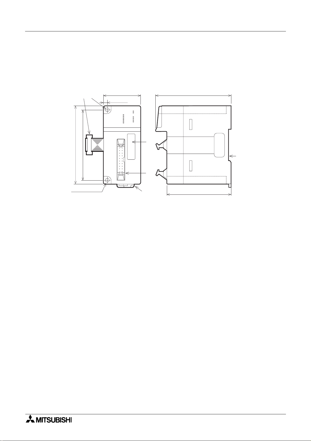
2.1 Outside dimensions
Unit: mm (inches)
b)a)
43(1.69")
4(0.16")
FX2N-10P G
START
DOG
X0
X1
φ
φ
POW ER
ERROR
PGO
FP
RP
A
CLR
B
87(3.43")
c)
90(3.54")
80(3.15")
f )
d)
4.5(φ0.18")
2-φ
e)
74(2.91")
External color: Munsell 0.08GY/7.64/0.81 Mass (Weight): Approx. 0.2kg (0.44lbs)
Accessories : Special block No. label
a) Extension cable
b) Direct mounting hole (2 - φ4.5/0.18”)
c) Extension port
d) Input/output port
e) DIN rail mounting hook
f) DIN rail mounting groove (DIN rail: DIN46277 35mm (1.38”) wide)
2-1
Page 18

Model FX2N-10PG Pulse Output Block Outside dimensions and component names 2
2.2 LED display
LED name State Display content
5V DC is not supplied through the extension cable from the
PLC.
CLR signal is output (when the origin point return is
completed)
POWER
START
ERROR
FP
RP
CLR
DOG
PG0
φ
A
φ
B
X0,X1
Unlit
Lit 5V DC is supplied through the extension cable from the PLC.
Unlit Start input off
Lit Start input on
Unlit Normal operation
Blinking Error occurred
Lit CPU error occurred
Unlit Forward pulse or pulse array interrupted.
Blinking Forward pulses or pulse array is being output.
Unlit Reverse pulse or directional output interrupted.
Blinking Reverse pulses or directional output is being output.
Unlit CLR signal is not output.
Lit
Unlit DOG input off
Lit DOG input on
Unlit Zero-point input off
Lit Zero-point input on
Unlit A-phase input of manual pulse generator off
Lit A-phase input of manual pulse generator on
Unlit B-phase input of manual pulse generator off
Lit B-phase input of manual pulse generator on
Unlit Interrupt input off
Lit Interrupt input on
2-2
Page 19
Model FX2N-10PG Pulse Output Block Outside dimensions and component names 2
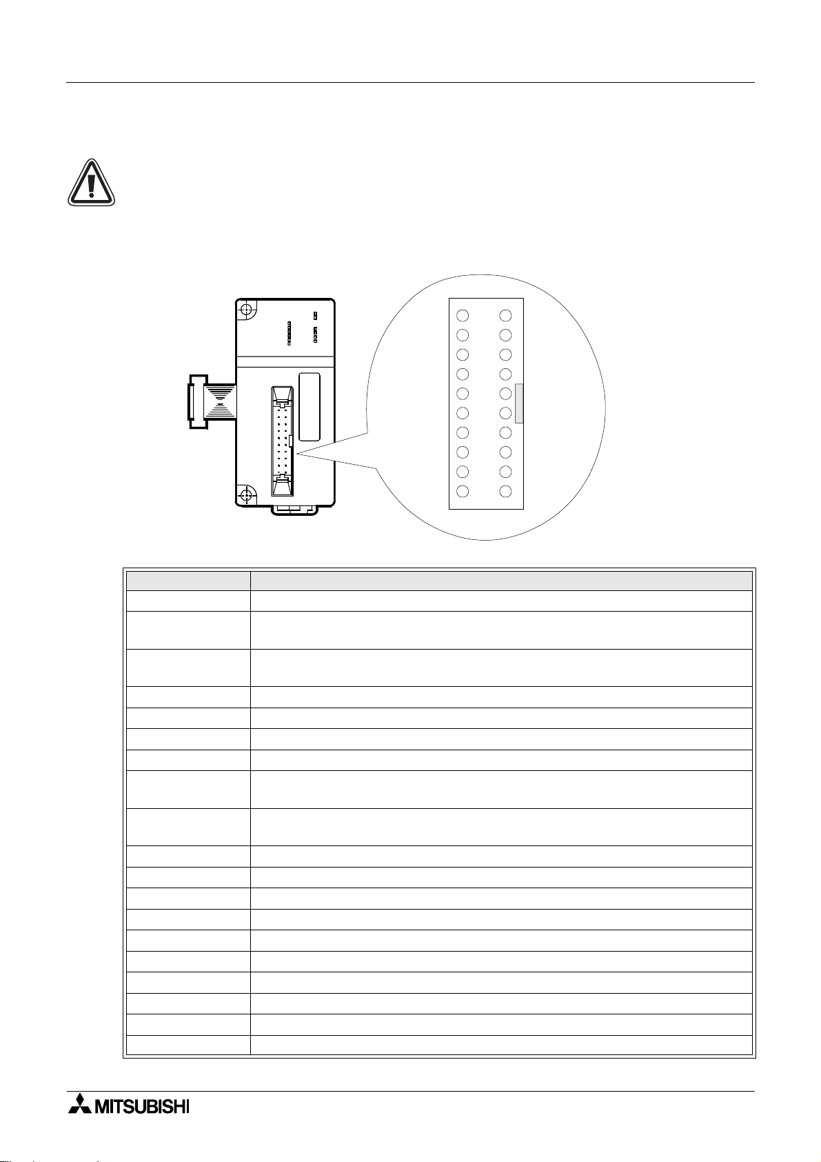
2.3 Pin layout and assignment
• The following pin layout is seen when looking at the I/O port in the FX2N-10PG from the
front face.
When an I/O cable and connecto r is prepare d by the user, the pin number mark an d
mark are different according to the connector used.
Wire correctly noting the position of notch and the direction of the connector.
I/O port in the FX2N-10P from the front face
POWER
FX2N-10PG
START
DOG
X0
X1
f
f
ERROR
PGO
FP
RP
A
CLR
B
VIN+
FP+
RP+
PG0+
CLR+
φ
A+
φ
B+
DOG
S/S
X0
VINFPRPPG0CLR-
φ
A-
φ
BSTART
S/S
X1
▲
Terminal name Content
VIN+ Power input terminal for pulse output 5V DC to 24V DC
FP+
RP+
Forward/reverse mode: Forward pulse output terminal
Pulse/direction mode: Pulse output terminal
Forward/reverse mode: Reverse pulse output termina l
Pulse/direction mode: Direction output terminal
PG0+ Zero-point signal input terminal
CLR+ Output terminal to clear the deviation counter of servo amplifier
φ
A+ A-phase input terminal of 2-phase pulse
φ
B+ B-phase input terminal of 2-phase pulse
DOG
S/S
Near-point DOG input terminal (Input terminal used for origin-point return
command)
Power input terminal (start, DOG, X0, X1) 24V DC
Pins (S/S) are internally short-circuited.
X0 Interrupt input terminal
VIN- Common terminal of VIN+
FP- Common terminal of FP+
RP- Common terminal of RP+
PG0- Common terminal of PG0+
CLR- Common terminal of CLR+
φ
A- Common terminal of A-phase input of 2-phase pulse
φ
B- Common terminal of B-phase input of 2-phase pulse
START Start input terminal
X1 Interrupt input terminal
2-3
Page 20

Model FX2N-10PG Pulse Output Block Outside dimensions and component names 2
2.3.1 Applicable connector and cable size
The connectors for the multi-wire cables are prepared as a set to allow the customer to
produce the input/output cables.
The cables and crimp tool should be prepared by the customer.
Model name and configuration of
input/output connector
Applicable cable and tool
Model name Cable size
FX
-I/O-CON-S
2C
For multi-wire cable: 5 sets
FX
-I/O-CON-SA
2C
For multi-wire cable: 5 sets
AWG22(0.3mm
AWG20(0.5mm
2
)
2
)
*1 Since it may be difficult to pass the random cable through the housing depending on the
variation of the sheath thickness, UL-1061 cable is recommended.
* Phoenix contact crimp tool.
2-4
Page 21
Model FX2N-10PG Pulse Output Block
3. Installation
Install FX2N-10PG on the right side of the basic unit, extension unit or other extension block of
FX
and FX2Nc Series PLC.
2N
For installation, install the block with DIN rail (DIN46277, 35mm (1.38inches) wide) or directly
with M4 screws.
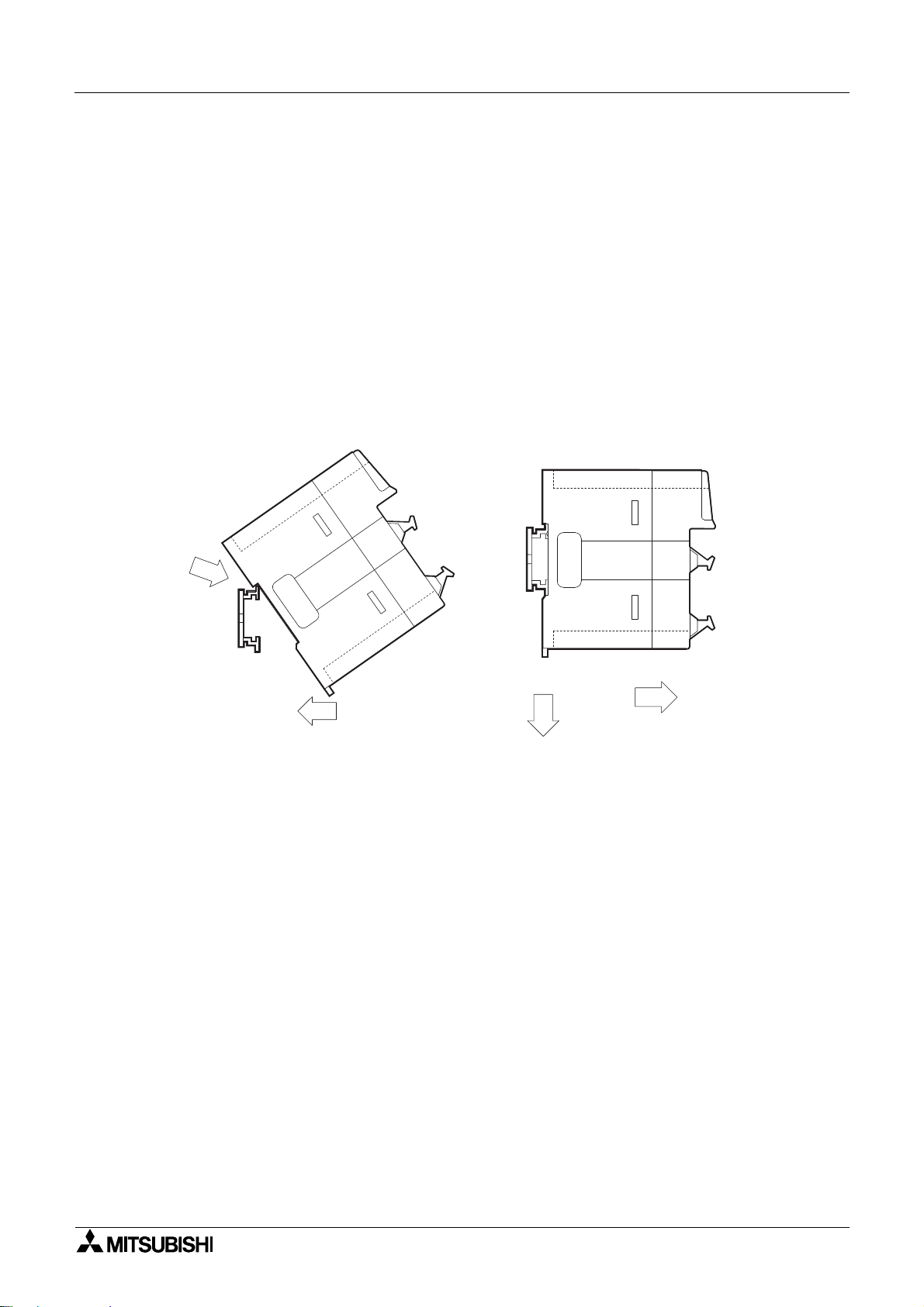
3.1 DIN rail installation
Align the upper side of the DIN rail mounting groove with t he DIN rail 1), and press the block in
2).
To remove the main body, pull out the DIN rail mounting hook downward 3), and remove the
block 4).
Installation Removal
Installation 3
1)
3.2 Direct installation
Pass M4 screws through the two mounting holes provided at the top and bottom on the left
side of FX
Provide a clearance of 1 to 2mm (0.08inches) between the units during installation.
-10PG, and install the block on the panel with the screws.
2N
2)
4)
3)
3-1
Page 22

Model FX2N-10PG Pulse Output Block Installation 3
Cautions regarding installation
1) Use the block under the envir onmental conditions specified in the manual.
Do not use the unit in a loca tion surrounded by dust, oil fumes, conductive dust, corrosive
gas or combustibl e gas, exposed to high temperature , condensation, wind or rai n, or subject
to vibration or impact.
Use in such a locati on may cause an electric shock, fire haza rd, mal functi on, or break age or
degradation of the product.
2) Before installation, wiring or similar work, be sure to switch off the external power supply to
isolate the block.
Otherwise, it may cause an electric shock or damage the product.
3) When tur ning on the power supply or operating the block after installation, wiring or similar
work, be sure to install the top cover.
4) When tapping a hole or routing a wire, prevent chips or wire chips from dropping into the
vent windows of FX
Such chips may cause a fire haza rd or malf unction.
-10PG.
2N
5) Securely fasten the extension cable to a specified connector.
If it is poorly connected, it will cause a malfunction.
3-2
Page 23
Model FX2N-10PG Pulse Output Block
4. System configuration
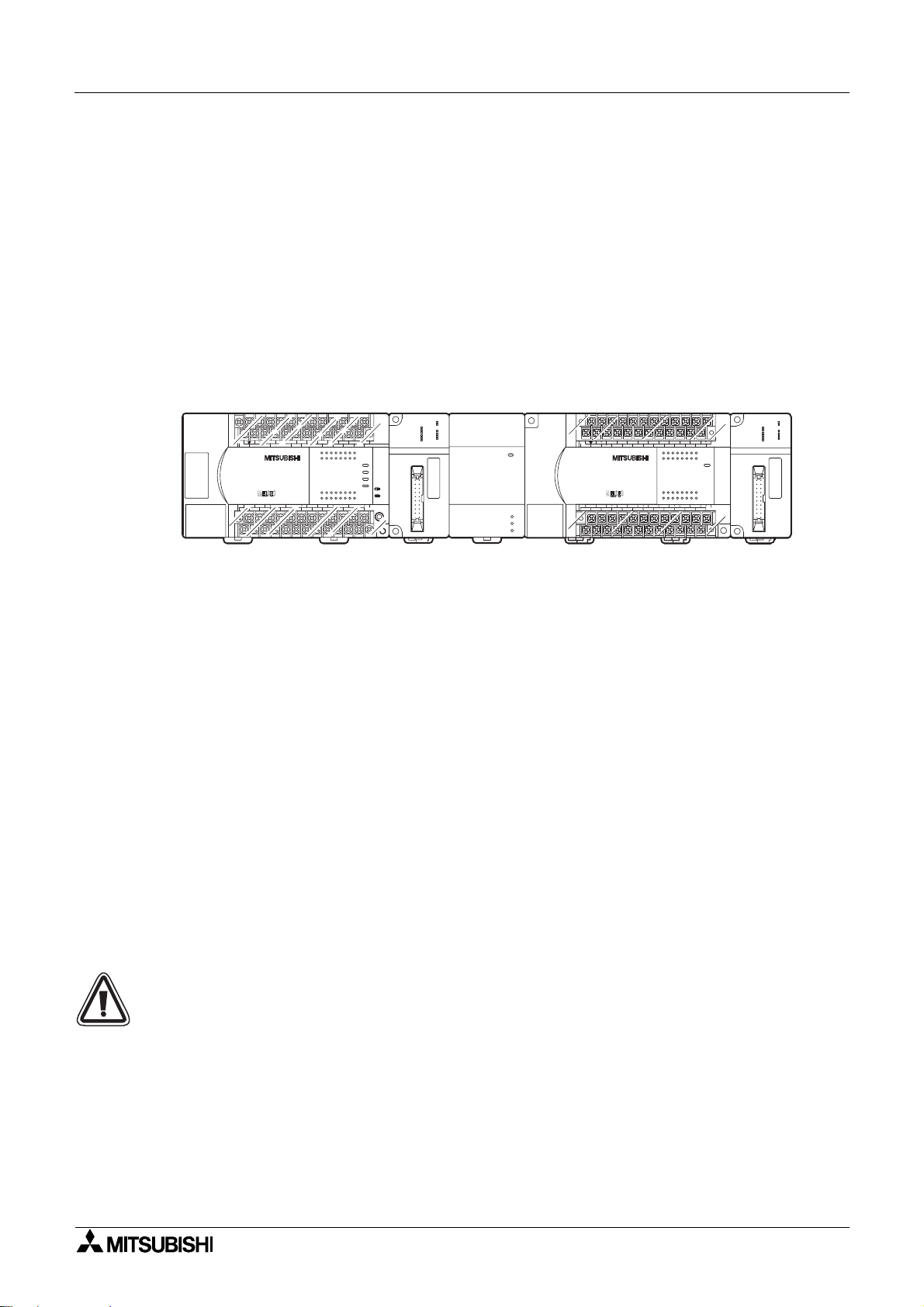
4.1 Connection with PLC
The PLC is connected to FX2N-10PG with the extension cable.
FX
-10PG is handled as a special unit of the PLC and is sequentially given the special unit
2N
number of 0 to 7 from the u nit which is the nearest to P LC. (The unit No. is instructed with
FROM/TO commands.)
For details of the input/output assignment of PLC, refer to the manual of FX
PLC.
System configuration 4
2N
, FX
2NC
Series
START
DOG
X0
X1
A
f
fB
FX2N -2 L C
POWER
ERROR
PGO
FP
RP
CLR
FX2N-2 L C
FX2N-3 2 E R
FX
Y7
FX2N-10 P G
POW ER
Special
2N -1 0 P G
START
DOG
X0
X1
A
f
fB
block
No.2
(X020 to X 037)
X0
X6 X0 X2 X4 X6
COM X4
POW ER
24V
OUT1
OUT2
Special
L X1X3X5X7
(Y020 to Y 037)
24+N
X3X2X1
FX2N-3 2 E R
X5
X7
IN
01234567
OUT
76543210
72456130
72456130
Y4Y5Y6
COM4COM2Y4Y5Y6Y7 COM3Y0Y1Y2Y3COM1Y0Y1Y2Y3
block
No. 1
Series PLC and a maximum of 4 units can
2N
-CNV-IF is required.
2NC
-65EC/FX0N-30EC extension cable and FX2N-
0N
POWER
ERROR
PGO
FP
RP
CLR
FX2N -3 2 M R
14 171510 12 13
1611
1611 1514 1710 12 13
Y14
Y15
72456130
POW ER
RUN
BATT.V
PROG .E
72456130
CPU.E
FX2N -1 0 P G
FX2N-10 P G
Special
(X000 to X 017)
24+N
FX2N-3 2M R
Y4Y5Y6
X10 X14 X16
X7
X3X2X1
IN
OUT
Y10
Y12
COM3
Y11
Y13Y1Y2Y3
COM X4
LX13X15
(Y000 to Y 017)
block
No. 0
• A maximum of 8 units can be connected to FX
be connected to FX
• When connected to FX
Series PLC.
2NC
Series PLC, FX
2NC
• For extension, the separately available FX
CNV-BC are used.
One extension cable can be used per system.
• The number of occupied I/O points of the FX
-10PG is 8. The total number of I/O points of
2N
the basic unit, extension unit and extension block and the occupied poin ts of the special
block must not exceed the max. number of the I/O points of the basic unit (256 points for
FX
and FX
2N
2NC
).
• The assignment of the I/O number of the PLC is shown in the parentheses. The I/O
connectors and occupied points of FX
-10PG are not included during assignment of I/O
2N
numbers of the PLC.
Turn OFF the power at first, then connect/disconnect the cab le such as an extension cable.
If you connect/disconnect a cable while the power is supplied, the unit may fail or malfunction.
4-1
Page 24

Model FX2N-10PG Pulse Output Block System configuration 4
4.2 Applicable PLC
Series name Applicable version
2N
Series All versions
FX
2NC
FX
Series All versions
For connection to FX
2NC
, FX
2NC
-CNV-IF is necessary.
4-2
Page 25

Model FX2N-10PG Pulse Output Block
5. Specifications
5.1 Environmental specifications
Item Specifications
Withstand voltage
Items except above
5.2 Power supply specifications
Item Specifications
Input
signal
Drive
power
supply
Inner
control
Output
signal
500V AC One minute (between all external terminals and ground terminal)
Same as the environmental specifications of the connected PLC
(Refer to the PLC manual.)
START, DOG, X0, X1 terminals: 24V DC+/-10%
Current consumption 32mA or less
PGO terminal: 3 to 5.5V DC Current consumption 20mA or less
VIN terminal: 5 to 24V DC Current consumption 100mA or less for 5V,
70mA or less for 24V
Each current can be supplied from the external power supply. (START, DOG,
X0, X1 terminals can be supplied from the service power supply (24+
terminal) of the PLC.)
5V DC Current consumption 120mA Power is supplied through the
extension cable from the PLC.
FP, RP terminals (Power supplied from VIN terminal 5 to 24V DC):
Set 25mA or less.
CLR: 5 to 24V DC Set 20mA or less.
Each is supplied from the servo amplifier or external power supply.
Specifications 5
5.3 Performance specifications
Item Specifications
Number of control
axes
Speed command
Position command
Positioning program
Number of I/O
occupied points
Start time
• One axis per unit
(Max. 8 units and 4 units can be connected to FX
FX
2NC
• The operation speed is set with the buffer memory.
• It can be operated at the pulse frequency of 1Hz to 1MHz.
• Hz, cm/min, 10 deg/min and inch/min are selectable for the command
unit.
• The travel is set with the buffer memory.
• The pulse converted value is in the range of -2,147,483,648 to
2,147,483,647. Pulse, mm, mdeg and 10
• The absolute position instruction and relative position instruction are
selectable.
• The magnification rates of 10
position data.
• Positioning is done in the PLC program.
(Data read-/writing and operation mode selection are instructed with
FROM/TO commands.)
• 8 points (Input or output.)
• 1 to 3ms
Series PLC respectively.)
0
, 101, 102 and 103 are settable for the
Series PLC and
2N
-4
inch are usable for the unit.
5-1
Page 26

Model FX2N-10PG Pulse Output Block Specifications 5
5.4 Input specifications
φφφφ
φφφφ
A,
Item START, DOG, X1
Number of input
points
Input signal
voltage
Signal format
Input signal
current
Input ON
sensitivity
Input OFF
sensitivity
Input receiving
speed
Circuit insulation
Operation
indication
Three control input points (START, DOG, PG0), two interrupt input points (X0, X1)
2-phase pulse input point (φA, φB)
24V DC ± 10% 3.0 to 5.5V DC 3.0 to 5.5V DC
Contact or open collector
transistor
6.5 ± 1mA 6 to 20mA 6 to 20mA
4.5mA or more 6.0mA or more 6.0mA or more
1.5mA or less 1mA or less 1mA or less
0.1ms or less
(1.0ms or less for DOG)
Photocoupler insulation
LED is lit when input is ON.
Differential line driver or
open collector transistor
2-phase pulse
30,000Hz or less
(Duty 50%)
B
Differential line driver or
open collector transisto r
Pulse width 50ms or more
PG0
5.5 Output specifications
Item Pulse output section Clear signal (CLR)
Number of output
points
Output system
Output type
Rated load
voltage
Max. load current
VIN current
consumption
Max. voltage drop
during ON
Leak current
during ON
Output frequency
Operation
indication
Three output points (FP, RP, CLR)
Forw ard pulse (FP) / reverse pulse (RP)
or pulse (PLS) / direction (DIR) is
selectable.
Differential line driver output NPN open collector transistor output
VIN 5 to 24V DC VIN 5 to 24V DC
25mA or less 20mA or less
24V DC: 70mA 5V DC: 100mA
FP+, RP+ Max. 1MHz 20 to 25ms
LED is lit when output is ON.
When zero return operation is
completed, it is turned on.
(Output pulse width: 20ms)
1.5V or less
0.1mA or less
5-2
Page 27
Model FX2N-10PG Pulse Output Block
6. Wiring
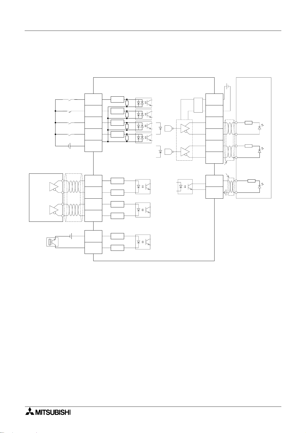
6.1 Input output circuit
Input terminal FX2N-10PG
Manual pulse
generator
7mA/24V DC
7mA/24V DC
7mA/24V DC
7mA/24V DC
24V DC
Shielded cable
A phase
START
DOG
X0
X1
S/S
φ
A+
3.3k
3.3k
3.3k
3.3k
120
Wiring 6
5 to
VIN+
VIN-
FP+
FP-
RP+
RP-
CLR+
24V DC
Shielded
cable
Servo amplifier
drive unit
Output terminal
Ω
Ω
Ω
Ω
AM26LS31 or equivalent
Differential line driver
Ω
5V
25mA or less
2-phase pulse
Frequency
30kHz or less
5V DC
20mA or less
B phase
A-
φ
B+
φ
B-
PG0+
PG0-
120
120
120
120
120
φ
• For the pin layout, refer to Section 2.3.
Ω
Ω
Ω
Ω
Ω
CLR-
5 to 24V DC
20mA or less
6-1
Page 28

Model FX2N-10PG Pulse Output Block Wiring 6
• Install a safety circuit outside the FX2N-10PG so that the entire system conservatively
operates even if an abnormality occurs in the external power supply or a failure occurs in
the FX
-10PG.
2N
1) Make sure to construct an emergency stop circuit, protection circuit, interlock circuit for
reverse operations such as normal rotation and reverse rotation and interlock circuit to
prevent damages of a machine for upper limit/lower limit, etc. outside the FX
-10PG.
2N
2) When the CPU in the detects an abnormality such as a watch dog timer error by the selfdiagnosis circuit, all outputs turn off. When an abnormality occurs in the I/O control area
which cannot be detected by the CPU in the FX
-10PG, output control may be disabled.
2N
Design external circuits and the structure so that the entire system conservatively
operates in such cases.
3) Do not lay signal cable near to high voltage power cable or house them in the same
trunking duct. Effects of noise or surge inductio n may occur. Keep signal cables a safe
distance of more than 100 mm (4”) from these power cables.
4) Where output signal lines are used over an extended distance consideration for voltage
drop and noise interference should be made.
5) Fix cables so that any stress is not directly applied on the terminal block or the cable
connection area.
6) When a failure occurs in a transistor etc. in the FX
-10PG, outputs may keep ON or
2N
OFF.
For output signals which may lead to severe accidents, design external circuits and the
structure so that the entire system conservatively operates.
• Make sure to shut down the power supplies of all phases on the outside before starting
installation or wiring.
If the power supplies are not shut down, you may get electrical shock or the unit may be
damaged.
• Never touch any terminals while the power is supplied.
If you touch a terminal while the power is supplied, you may get electrical shock or the
unit may malfuncti on.
• Turn off the power at first, then start cleaning or tighten terminals.
If you perform cleaning or tightening while the power is supplied, you may get electrical
shock.
• For pairs of inputs such as forward/reverse contacts which would pose a hazard if turned
ON simultaneously, provide external interlocks, in addition to interlocks in the program
inside the positioning unit, to ensure that they cannot be turned ON simultaneously.
Forward
lim it
Forward
Reverse
lim it
Reverse
O utput elem ent
6-2
Page 29
Model FX2N-10PG Pulse Output Block Wiring 6
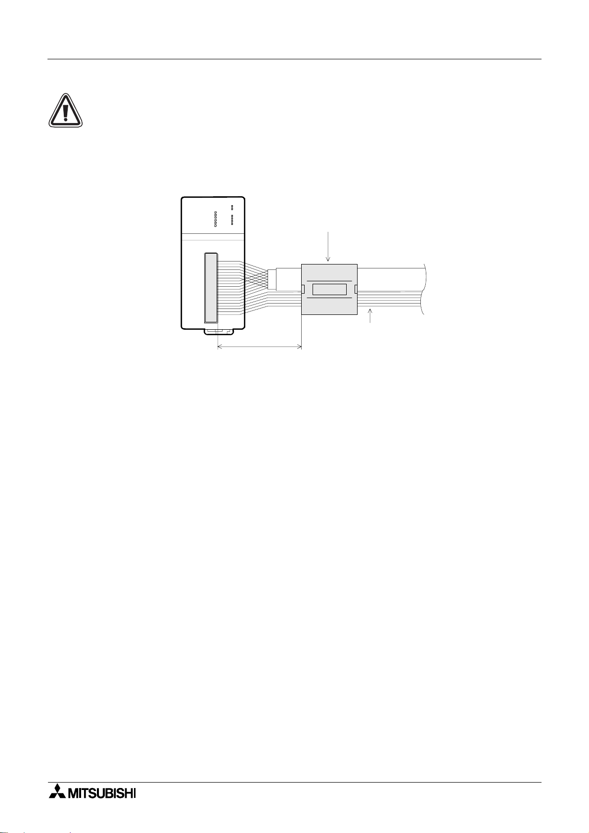
CE MEC Conformity
For compliance to EC EMC regulation it is necessary to add a Ferrite filter on the I/O cable of
the FX
-10PG.
2N
The filter should be attached below with the filter surrounding the I/O cable.
The recommended ferrite filter is the TOKIN ESD-SR-25 or equivalent. The filter should be
placesd as near to I/O port the FX
2N
-10PG
FX
POWER
ERROR
START
DOG
PGO
X0
FP
FX2N-10PG
X1
RP
fA
CLR
f
B
150mm (5.9") or less
-10PG as possible.
2N
Ferrite filter
TOKIN ESD-SR-25
TOKIN
I/O cable
6-3
Page 30
Model FX2N-10PG Pulse Output Block Wiring 6
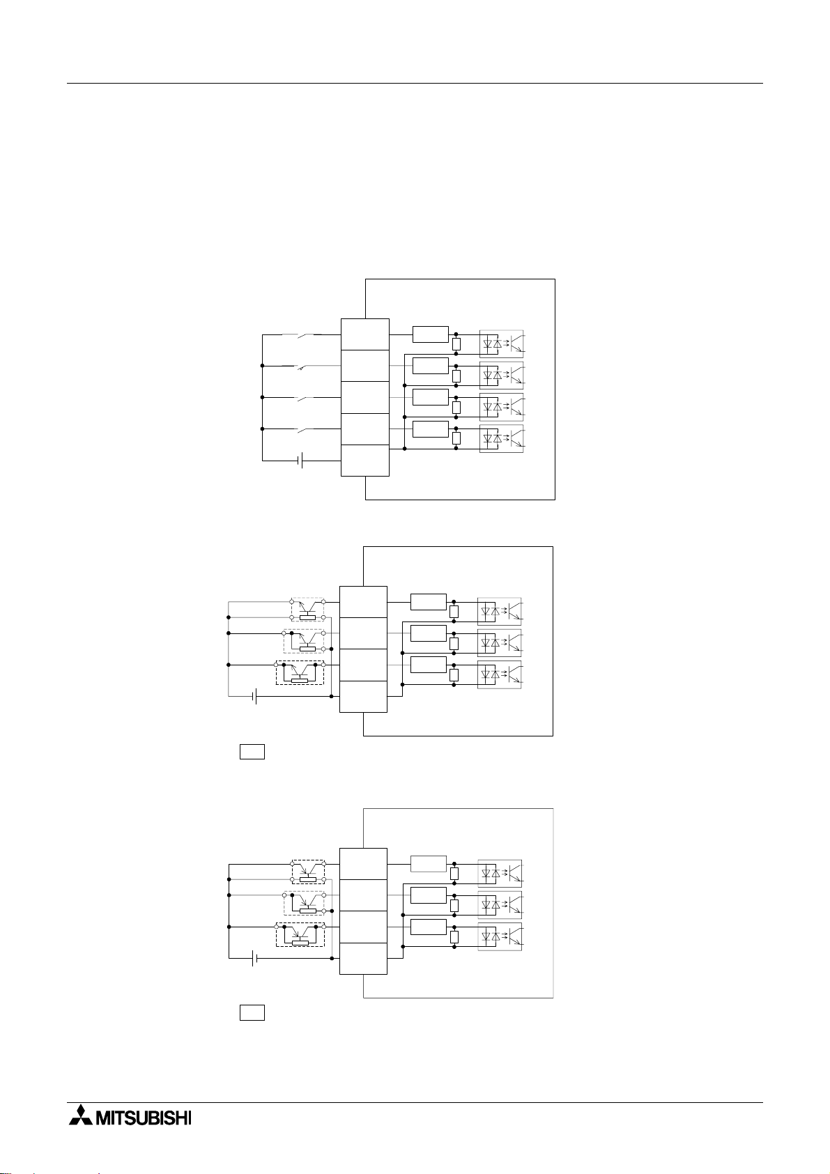
6.2 Input wiring
6.2.1 START, DOG, X0, X1, S/S
External power supply (24V DC) is required for terminals START, DOG, X0, X1 and S/S.
Contact output type and open collector transistor output (NPN, PNP) types of external devices
are applicable.
1) When contacts are used
FX2N-10PG
Input terminal
7mA/24V DC
START
7mA/24V DC
DOG
7mA/24V DC
X0
7mA/24V DC
X1
24V DC
S/S
3.3k
3.3k
3.3k
3.3k
Ω
Ω
Ω
Ω
2) When NPN open collector transistors are used
FX2N-10PG
Input terminal
4-wire type
3-wire type
2-wire type
24V DC
Reread terminal as START, DOG, X0 or X1 according to the application.
IN
IN
IN
IN
S/S
3.3k
3.3k
3.3k
Ω
Ω
Ω
3) When PNP open collector transistors ar e used
FX2N-10PG
Input terminal
4-wire type
3-wire type
2-wire type
24V DC
IN
IN
IN
S/S
3.3k
3.3k
3.3k
Ω
Ω
Ω
Reread terminal as START, DOG, X0 or X1 according to the application.
IN
• For the pin layout, refer to Section 2.3.
6-4
Page 31

Model FX2N-10PG Pulse Output Block Wiring 6
6.2.2 A-phase +, A-phase -, B-phase +, B-phase -
The different ial line driv er or the open co llect or tran sistor output type man ual pulse gener ator is
applicable to the terminals φA+, φA-, φB+ and φB-.
External power supply (5V DC) is required for the open collector transistor output.
1) When a differential line driver is used
FX2N-10PG
Input terminal
φ
A+
φ
A-
φ
B+
φ
B-
Manual pulse
generator
2-phase pulse
Frequency
30kHz or less
Power supply
Shielded
cable
A phase
B phase
2) When NPN open collector transistors are used
Manual pulse
generator
Shielded
cable
A phase
B phase
FX2N-10PG
Input terminal
φ
A+
φ
A-
φ
B+
φ
B-
120
120
120
120
120
120
120
120
Ω
Ω
Ω
Ω
Ω
Ω
Ω
Ω
5V DC
• For the pin layout, refer to Section 2.3.
6-5
Page 32

Model FX2N-10PG Pulse Output Block Wiring 6
6.2.3 PGO+, PGO-
External power supply (5V DC) is required for the terminals PGO+ and PG0-.
The external device of the differential line driver output type or open collector transistor output
(NPN/PNP) type is applicable.
1) When a differential line driver is used
FX2N-10PG
Photocoupler
PG0+
120
Ω
PG0-
Power supply
2) When NPN open collector transistor is use d
FX2N-10PG
PG0+
5V DC
20mA or less
PG0-
3) When PNP open collector transistor is use d
FX2N-10PG
PG0+
5V DC
20mA or less
PG0-
120
120
120
120
120
Ω
Photocoupler
Ω
Ω
Photocoupler
Ω
Ω
• For the pin layout, refer to Section 2.3.
6-6
Page 33

Model FX2N-10PG Pulse Output Block Wiring 6
6.3 Output wiring
6.3.1 VIN+, VIN-, FP+, FP-, RP+, RP-
The terminals VIN+, VIN-, FP+, FP-, RP+ and RP- are connected to the servo amplifier and
motor driver.
5 to 24V DC is supplied to the terminals VIN+ and VIN- from the external power supply or
servo amp lif ie r.
The terminals FP+, FP-, RP+ and RP- are used for the differential line driver output.
1) Connection to differential line receiver
2N
-10PG
FX
M26LS31 or equivalent
Differential line driver
25mA or less
Output terminal
5V
2) Connection to photocoupler
FX2N-10PG
Output terminal
5V
VIN+
VIN-
FP+
FP-
RP+
RP-
VIN+
VIN-
5 to 24V DC
Shielded
cable
5 to 24V DC
Servo amplifier
drive unit
AM262LS32 or
equivalent
Differential line
receiver
Servo amplifier
drive unit
FP+
FP-
RP+
RP-
M26LS31 or equivalent
Differential line driver
25mA or less
• For the pin layout, refer to Section 2.3.
Shielded
cable
6-7
Page 34

Model FX2N-10PG Pulse Output Block Wiring 6
6.3.2 CLR+, CLR-
The terminals CLR+ and CLR- are connected to the servo amplifier.
5 to 24V DC is supplied to the terminals CLR+ and CLR- from the external power supply or
servo amp lif ie r.
CLR+ and CLR- are used for the NPN open collector output.
FX2N-10PG
CLR+
CLR-
• For the pin layout, refer to Section 2.3.
5 to 24V DC
20mA or less
Shielded
cable
Servo amplifier
drive unit
6-8
Page 35

Model FX2N-10PG Pulse Output Block Wiring 6
6.4 Connection with stepping motor
FX2N/FX
2NC
FX2N-10PG
24V DC
3.3k
3.3k
3.3k
3.3k
3.3k
3.3k
3.3k
3.3k
3.3k
3.3k
3.3k
3.3k
3.3k
120
120
120
Ω
Ω
Ω
Ω
Ω
Ω
Ω
Ω
Ω
Ω
Ω
Ω
Ω
Ω
Ω
Ω
L
N
COM
X***
X***
X***
X***
X***
X***
X***
X***
X***
START
DOG
X0
X1
S/S
A+
φ
A-
φ
φ
B+
24V DC/7mA
24V DC/7mA
24V DC/7mA
24V DC/7mA
24V DC
A Phase
B Phase
Class D
ground
Manual pulse
generator
Power supply
DC power type is
also available on the
PLC.
.
Pin layout of p or t in FX2N-10PG
STOP
Error reset
Forward limit
Reverse limit
Forward jog
Reverse jog
Zero return
command
Operation speed
change enable
m code OFF
command
2-phase pulse
Frequency 30kHz or less
For the power supply wiring of the driver unit
and the connection of the motor, refer to the
instruction manuals of the drive and unit.
VIN+
FP+
RP+
PG0+
CLR+
A+
φ
φ
B+
DOG
S/S
X0
.
The above pin layout is seen when looking
at the I/O port in the FX
front face.
When an I/O cable and conne ctor is
prepared by the us er, the pin number m ark
▲
mark are different according to the
and
connector used.
Wire correct ly noting the position of notch
and the directio n of the connector .
VINFPRPPG0CLR-
A-
φ
φ
BSTART
S/S
X1
2N
-10PG from the
Ω
120
Ω
120
Ω
120
5V
AM26LS31 or equivalent
Differential line
driver 25mA or less
φ
B-
PG0+
PG0-
VIN+
VIN-
FP+
FP-
RP+
RP-
CLR+
CLR-
Shielded
cable
5V DC
5 to 4V DC
Shielded cable
CW-
CW+
CCW-
CCW+
Drive unit
Stepping
motor
6-9
Page 36

Model FX2N-10PG Pulse Output Block Wiring 6
6.5 Connection with Model MR-C Servo Motor
FX
/FX
2N
2NC
FX2N-10PG
24V DC
3.3k
3.3k
3.3k
3.3k
3.3k
3.3k
3.3k
3.3k
3.3k
3.3k
3.3k
3.3k
3.3k
120
120
120
120
120
120
5V
Ω
Ω
Ω
Ω
Ω
Ω
Ω
Ω
Ω
Ω
Ω
Ω
Ω
Ω
Ω
Ω
Ω
Ω
Ω
L
N
COM
X***
X***
X***
X***
X***
X***
X***
X***
X***
START
DOG
X0
X1
S/S
A+
φ
A-
φ
φ
B+
φ
B-
PG0+
PG0-
VIN+
VIN-
FP+
FP-
RP+
24V DC/7mA
24V DC/7mA
24V DC/7mA
24V DC/7mA
24V DC
A Phase
B Phase
Shielded
cable
Class D
ground
Manual pulse
generator
Power supply
DC power type is
also available on the
PLC.
.
Pin layout of por t in FX2N-10PG
STOP
Error reset
Forward limit
Reverse limit
Forward jog
Reverse jog
Zero return
command
Operation speed
change enable
m code OFF
command
2-phase pulse
Frequency 30kHz or less
For the power supply wiring of the servo
amplifier and the connection of the motor,
refer to the instruction manual and technical
data of the servo amplifier.
CN1 CN1
11
1
4
CN1
16
9
10
7
VIN+
FP+
RP+
PG0+
CLR+
A+
φ
φ
B+
DOG
S/S
X0
.
The above pin layout is seen when looking
at the I/O port in the FX
front face.
When an I/O cable and connec tor is
prepared by the us er, the pin number m ar k
▲
mark are different according to the
and
connector used.
Wire correct ly noting the position of notch
and the direction of the connector.
Servo amplifier
SD
V+
OP
V5
PP
PG
NP
ALM
V5
SG
SON
LSP
LSN
VINFPRPPG0CLR-
A-
φ
φ
BSTART
S/S
X1
2
CN1
16
12
17
15
14
2N
-10PG from the
RA1
5V DC
AM26LS31 or equivalent
Differential line
driver 25mA or less
RP-
CLR+
CLR-
Shielded cable
8
CN1
13
12
NG
CR
SG
6-10
Page 37

Model FX2N-10PG Pulse Output Block Wiring 6
6.6 Connection with Model MR-J Servo Motor
FX
/FX
2N
2NC
FX2N-10PG
24V DC
3.3k
3.3k
3.3k
3.3k
3.3k
3.3k
3.3k
3.3k
3.3k
3.3k
3.3k
3.3k
3.3k
120
120
120
120
120
120
5V
Ω
Ω
Ω
Ω
Ω
Ω
Ω
Ω
Ω
Ω
Ω
Ω
Ω
Ω
Ω
Ω
Ω
Ω
Ω
L
N
COM
X***
X***
X***
X***
X***
X***
X***
X***
X***
START
DOG
X0
X1
S/S
A+
φ
A-
φ
φ
B+
φ
B-
PG0+
PG0-
VIN+
24V DC/7mA
24V DC/7mA
24V DC/7mA
24V DC/7mA
A Phase
B Phase
Shielded
cable
5 to
24V DC
Class D
ground
24V DC
Manual pulse
generator
Power supply
DC power type is
also available on the
PLC.
.
Pin layout of por t in FX2N-10PG
STOP
Error reset
Forward limit
Reverse limit
Forward jog
Reverse jog
Zero return
command
Operation speed
change enable
m code OFF
command
2-phase pulse
Frequency 30kHz or less
For the power supply wiring of the servo
amplifier and the connection of the motor,
refer to the instruction manual and technical
data of the servo amplifier.
CN1
18
5V DC
6
12
CN1
35
VIN+
FP+
RP+
PG0+
CLR+
A+
φ
φ
B+
DOG
S/S
X0
.
The above pin layout is seen when looking
at the I/O port in the FX
front face.
When an I/O cable and conne ctor is
prepared by the us er, the pin number m ark
▲
mark are different according to the
and
connector used.
Wire correct ly noting the position of notch
and the directio n of the connector.
Servo amplifier
SD
LG
OP
VDD
VIN
ZSP
VINFPRPPG0CLR-
A-
φ
φ
BSTART
S/S
X1
CN1
34
26
2N
-10PG from the
AM26LS31 or equivalent
Differential line
driver 25mA or less
VIN-
FP+
FP-
RP+
RP-
CLR+
CLR-
Shielded cable
34
20
19
22
21
CN1
32
15
VIN
PP
PG
NP
NG
CR
SG
PF
ALM
RES
SON
LSP
LSN
SG
25
27
CN1
29
28
30
31
15
RA1
6-11
Page 38

Model FX2N-10PG Pulse Output Block Wiring 6
6.7 Connection with Model MR-J2 (-Jr, -Super) Servo Motor
FX
/FX
2N
2NC
FX2N-10PG
24V DC
Ω
3.3k
3.3k
Ω
3.3k
Ω
3.3k
Ω
3.3k
Ω
3.3k
Ω
Ω
3.3k
Ω
3.3k
Ω
3.3k
3.3k
Ω
Ω
3.3k
Ω
3.3k
Ω
3.3k
120
Ω
120
Ω
Ω
120
Ω
120
Ω
120
120
Ω
5V
AM26LS31 or equivalent
Differential line
driver 25mA or less
L
N
COM
X***
X***
X***
X***
X***
X***
X***
X***
X***
START
DOG
X0
X1
S/S
A+
φ
A-
φ
φ
B+
φ
B-
PG0+
PG0-
VIN+
VIN-
FP+
FP-
RP+
RP-
CLR+
24V DC/7mA
24V DC/7mA
24V DC/7mA
24V DC/7mA
A Phase
B Phase
Shielded
cable
5 to
24V DC
Class D
ground
24V DC
Manual pulse
generator
Power supply
DC power type is
also available on the
PLC.
.
Pin layout of por t in FX2N-10PG
STOP
Error reset
Forward limit
Reverse limit
Forward jog
Reverse jog
Zero return
command
Operation speed
change enable
m code OFF
command
2-phase pulse
Frequency 30kHz or less
For the power supply wiring of the servo
amplifier and the connection of the motor,
refer to the instruction manual and technical
data of the servo amplifier.
CN1A
Case
5
15
CN1B
3
CN1A
9
3
13
2
12
CN1A
8
VIN+
FP+
RP+
PG0+
CLR+
A+
φ
φ
B+
DOG
S/S
X0
.
The above pin layout is seen when looking
at the I/O port in the FX
front face.
When an I/O cable and conne ctor is
prepared by the us er, the pin number m ark
▲
mark are different according to the
and
connector used.
Wire correct ly noting the position of notch
and the directio n of the connector.
Servo amplifier
SD
LZ
LZR
VDD
COM
PP
PG
NP
NG
CR
VDD
ZSP
TLC
ALM
EMG
SON
LSP
LSN
VINFPRPPG0CLR-
A-
φ
φ
BSTART
S/S
X1
CN1B
3
19
6
18
CN1B
15
5
16
17
2N
-10PG from the
RA1
CLR-
Shielded cable
SG
10
SG
10
6-12
Page 39

Model FX2N-10PG Pulse Output Block Wiring 6
6.8 Connection with Model MR-H Servo Motor
FX
/FX
2N
2NC
FX2N-10PG
24V DC
3.3k
3.3k
3.3k
3.3k
3.3k
3.3k
3.3k
3.3k
3.3k
3.3k
3.3k
3.3k
3.3k
120
120
120
120
120
Ω
Ω
Ω
Ω
Ω
Ω
Ω
Ω
Ω
Ω
Ω
Ω
Ω
Ω
Ω
Ω
Ω
Ω
L
N
COM
X***
X***
X***
X***
X***
X***
X***
X***
X***
START
DOG
X0
X1
S/S
A+
φ
A-
φ
φ
B+
φ
B-
PG0+
24V DC/7mA
24V DC/7mA
24V DC/7mA
24V DC/7mA
24V DC
A Phase
B Phase
Shielded
cable
Class D
ground
Manual pulse
generator
Power supply
DC power type is
also available on the
PLC.
.
Pin layout of por t in FX2N-10PG
STOP
Error reset
Forward limit
Reverse limit
Forward jog
Reverse jog
Zero return
command
Operation speed
change enable
m code OFF
command
2-phase pulse
Frequency 30kHz or less
For the power supply wiring of the servo
amplifier and the connection of the motor,
refer to the instruction manual and technical
data of the servo amplifier.
CN1
50
8
VIN+
FP+
RP+
PG0+
CLR+
A+
φ
φ
B+
DOG
S/S
X0
.
The above pin layout is seen when looking
at the I/O port in the FX
front face.
When an I/O cable and conne ctor is
prepared by the us er, the pin number m ark
▲
mark are different according to the
and
connector used.
Wire correct ly noting the position of notch
and the directio n of the connector.
Servo amplifier
SD
LZ
VDD
ZSP
VINFPRPPG0CLR-
A-
φ
φ
BSTART
S/S
X1
CN1
22
23
2N
-10PG from the
120
Ω
5V
AM26LS31 or equivalent
Differential line
driver 25mA or less
PG0-
VIN+
VIN-
FP+
FP-
RP+
RP-
CLR+
CLR-
5 to
24V DC
Shielded cable
9
CN1
22
20
10
11
35
36
CN1
37
17
LZR
VDD
VIN
PP
PPR
NP
NPR
CR
SG
PF
ALM
EMG
EMG
SON
SON
LSP
RES
LSP
LSN
SG
24
48
CN1
46
12
15
38
34
40
RA1
6-13
Page 40

Model FX2N-10PG Pulse Output Block Wiring 6
MEMO
6-14
Page 41

Model FX2N-10PG Pulse Output Block
7. Buffer memory (BFM)
7.1 BFM list
Buffer memory (BFM) 7
BFM No. Name Content and setting range
-2,147,483,648 to 2,147,483,467
#1 #0 Max. speed
#2 Bias speed
#4 #3 Jog speed
#6 #5
#10 #9 Zero point address
#14 #13 Target address
#16 #15 Operation speed
#18 #17 Target address
#20 #19 Operation speed
#23 #22
#25 #24 Current address -2,147,483,648 to 2,147,483,467
Zero return speed
(high speed)
Zero return speed
#7
(creep)
Zero-point signal
#8
number
(S-shaped control)
#11 Acceleration time
#12 Deceleration time
Ι
ΙΙ
#21 Override setting 1 to 30,000
Current value,
operation speed
#26 Operation command Refer to 7.2.17
#27 Operation pattern Refer to 7.2.18
(The pulse-converted value of
1 to 1,000,000Hz)
-2,147,483,648 to 2,147,483,467
(The pulse-converted value of
0 to 30,000Hz)
-2,147,483,648 to 2,147,483,467
(The pulse-converted value of
1 to 1,000,000Hz)
-2,147,483,648 to 2,147,483,467
(The pulse-converted value of
1 to 1,000,000Hz)
-2,147,483,648 to 2,147,483,467
(The pulse-converted value of
0 to 30,000Hz)
0 to 32.767
-2,147,483,648 to 2,147,483,467
(The pulse-converted value of
-2,147,483,648 to 2,147,483,467)
1 to 5,000ms (trapezoidal control)
64 to 5,000ms (S-shaped control)
1 to 5,000ms (trapezoidal control)
64 to 5,000ms (S-shaped control)
-2,147,483,648 to 2,147,483,467
(The pulse-converted value of
-2,147,483,648 to 2,147,483,467)
-2,147,483,648 to 2,147,483,467
(The pulse-converted value of
Ι
1 to 1,000,000Hz)
-2,147,483,648 to 2,147,483,467
(The pulse-converted value of
-2,147,483,648 to 2,147,483,467)
-2,147,483,648 to 2,147,483,467
(The pulse-converted value of
ΙΙ
1 to 1,000,000Hz)
-2,147,483,648 to 2,147,483,467
(The pulse-converted value of
1 to 1,000,000Hz)
Initial
value
500,000
0
10,000
500,000
1,000
1
0
100
100
0
500,000
0
100,000
1000
0
0
H000
H000
Unit Attribute
User
unit
User
unit
User
unit
User
unit
User
unit
Pulse R/W
User
unit
ms R/W
ms R/W
User
unit
User
unit
User
unit
User
unit
0.1% R/W
×
User
unit
User
unit
R/W
R/W
R/W
R/W
R/W
R/W
R/W
R/W
R/W
R/W
R
R/W
R/W
R/W
7-1
Page 42

Model FX2N-10PG Pulse Output Block Buffer memory (BFM) 7
BFM No. Name Content and setting range
#28 Status information Refer to 7.2.19
#29 M code
#30 Machine model code K5120
#31 Not usable.
#33 #32 Pulse rate 1 to 999,999 PLS/REV
#35 #34 Feed rate 1 to 999,999 µm/REV
#36 Parameter Refer to 7.2.24
#37 Error code Occured error code is stored.
#38 Terminal information
Current address
#40 #39
#42 #41
#44 #43
#48 to #63 Not usable.
#65 to #97 Not usable.
#101 #100
#103 #102
#104
(pulse converted
value)
Manual pulse
generator input
current value
Manual pulse
generator input
frequency
Electronic gear
(numerator) for
#45
manual pulse
generator input
Electronic gear
(denominator) for
#46
manual pulse
generator input
Manual pulse
#47
generator input
response
#64
Version information
#98
Table start No.
#99
Executing table No.
Position information
(Table No. 0)
Speed information
(Table No. 0)
m code information
(Table No. 0)
During M code ON : 0 to 32,767
During M code OFF: -1
ON/OFF information of the terminal
input is stored.
-2,147,483,648 to 2,147,483,467
-2,147,483,648 to 2,147,483,467
0 to ±30,000
1 to 32,767
1 to 32,767
1, 2, 3, 4, 5
(Low response → High response)
0 to 199
-1 to 199
-2,147,483,648 to 2,147,483,467
(The pulse-converted value of
-2,147,483,648 to 2,147,483,467)
-2,147,483,648 to 2,147,483,467
(The pulse-converted value of
1 to 1,000,000Hz)
-1 to 32,767
Operation
#105
information (Table
-1 to 4
No. 0)
Initial
value
-1
5120
2,000
2,000
H2000
0
0
0
0
0
1
1
3
0
-1
-1
-1
-1
-1
Unit Attribute
Pulse R/W
mR/W
µ
Pulse R/W
Pulse R/W
Hz R
User
unit
User
unit
R
R
R
R/W
R
R/W
R/W
R/W
R/W
R
R/W
R
R/W
R/W
R/W
R/W
7-2
Page 43

Model FX2N-10PG Pulse Output Block Buffer memory (BFM) 7
BFM No. Name Content and setting range
-2,147,483,648 to 2,147,483,467
(The pulse-converted value of
-2,147,483,648 to 2,147,483,467)
-2,147,483,648 to 2,147,483,467
(The pulse-converted value of
1 to 1,000,000Hz)
-1 to 32,767
#107 #106
#109 #108
#110
Position information
(Table No. 1)
Speed information
(Table No. 1)
m code information
(Table No. 1)
Operation
#111
information
-1 to 4
(Table No. 1)
.
.
.
#1295 #1294
#1297 #1296
#1298
Position information
(Table No. 199)
Speed information
(Table No. 199)
m code information
(Table No. 199)
-2,147,483,648 to 2,147,483,467
(The pulse-converted value of
-2,147,483,648 to 2,147,483,647)
-2,147,483,648 to 2,147,483,467
(The pulse-converted value of
1 to 1,000,000Hz)
-1 to 32,767
.
.
.
Operation
#1299
information
-1 to 4
(Table No. 199)
Initial
value
-1
-1
-1
-1
-1
-1
-1
-1
Unit Attribute
User
unit
User
unit
User
unit
User
unit
R/W
R/W
R/W
R/W
R/W
R/W
R/W
R/W
7-3
Page 44

Model FX2N-10PG Pulse Output Block Buffer memory (BFM) 7
• A single buffer memory No. is used for 16-bit data, and that of a serial buffer memory No. is
used for 32-bit data.
Use the 16-bit command (FROM/TO) for the buffer memory of 16-bit data.
Use the 32-bit command ( FROM/ TO) for the buffer memory of 32-bit data.
D D
Treat the m code information (B FM#104, #110, ..... #248) and operation information
(BFM#105, #111, ..... #1299) as 32-bit data.
MOV K1 D0
MOV K0 D1
TODK0 K104 D0 K1
K1→D0
K0
D0→BFM#104
D1→BFM#105
m code 1
Operation information 0
→
D1
(Step-advance operation)
• Attribute: W ... Writing R ... Reading
• Unit : User unit ... Varies as the system unit (BFM#36) is set.
7-4
Page 45

Model FX2N-10PG Pulse Output Block Buffer memory (BFM) 7
7.2 Details of BFM
7.2.1 BFM#1, #0 Maximum speed
The upper limit of the speed in each operation mode.
Set the bias speed (BFM#2), jog speed (BFM#3, #4), zero return speed (high speed) (BFM#5,
#6), zero return speed (creep) (BFM#7), operation speed Ι (BFM#15, #16) and operation
speed ΙΙ (BFM#19, #20) to be less than the maximum speed.
The setting unit varies as "system unit" (BFM#36) is set.
Here, the inclination of ac-/deceration is deter mined dep ending on the maximum speed , bias
speed (BFM#2), acceleration time (BFM#1 1) and deceleration time (BFM#12).
7.2.2 BFM#2 Bias speed
The start speed.
If it is used in combination with FX
resonant area and self-start frequency.
The inclination of the ac-/deceleration is determined depending on the settings of the
maximum speed, bias speed, accelerat ion time and deceleration time.
7.2.3 BFM#4, #3 Jog speed
-10PG and stepping motor, set the speed, considering the
2N
The speed during manual forward/reverse (JOG+/JOG-) operation.
Set the jog speed in the range between the bias speed (BFM#2) and maximum speed
(BFM#0, #1).
(Maximum speed > Jog speed > Bias speed)
When the jog speed is set at the maximum speed or more, it is operated at the maximum
speed, and if the jog speed is at the bias speed or less, it is operated at the bias speed.
When operation speed change (BFM#26 b10) is allowed (OFF), the speed during jog
operation can be changed.
7.2.4 BFM#6, #5 Zero return speed (high speed)
The high return speed during machine zero return operation.
Set the zero return speed (high speed) in the range between the bias speed (BFM#2) and
maximum speed (BFM#0, #1).
When operation speed change (BFM#26 b10) is allowed (OFF), the speed during zero return
operation can be changed.
7.2.5 BFM#7 Zero return speed (creep)
The speed is set for slow-speed operation after input of the near-point signal (DOG) during
machine zero return operation.
To improve the precision of the zero position, set to be as slow as possible.
When operation speed change (BFM#26 b10) is allowed (OFF), the speed during zero return
operation can be changed.
7.2.6 BFM#8 Zero-point signal number
The number of zero-point signals from dog input ON or OFF (the co unt timing is set with
BFM#36) to the stop is set.
The zero-point signal is counted when the leading edge is detected.
When the setting value is "0", it is immediately stopped if the dog input is turned to ON or OFF.
At this time, it is immediately stopped from the zero return speed (BFM#6, #5).
If a machine may be broken due to immediate stop, the value can be set to stop the machine
after the safety speed is gained at the creep speed (BFM#7).
7-5
Page 46

Model FX2N-10PG Pulse Output Block Buffer memory (BFM) 7
7.2.7 BFM#10, #9 Zero-point address
The address of the current value at the completion time of zero return operation is set.
When the zero return operation is completed, the value is written at the current address
(BFM#40, #39).
Here, the user unit (BFM#36) is selected, and the value which also includes the magnification
(BFM#36) of the position data is selected.
7.2.8 BFM#11 Acceleration time
The time from the bias speed (BFM#2) to the maximum speed (BFM#1, #0).
The inclination of the acce leration is determ ined depending on the bias sp eed (BFM#2),
maximum speed (BFM#1, #0) and acceleration time.
The settable range is 1 to 5000ms.
It is operated at 1ms for 0ms or less, and at 5000ms for 5001ms or more.
To use an approx. S-shaped ac-/deceleration control, set 64ms or more.
7.2.9 BFM#12 Deceleration time
The time from the maximum speed (BFM#1, #0) to the bias speed (BFM#2).
The inclination of the deceleration is deter mined depending on the bias speed (BFM#2),
maximum speed (BFM#1, #0) and deceleration time.
The settable range is 1 to 5000ms.
It is operated at 1ms for 0ms or less, and at 5000ms for 5001ms or more.
To use an approx. S-shaped ac-/deceleration control, set 64ms or more.
7.2.10 BFM#14, #13 Target address
ΙΙΙΙ
The target position (absolute address) or travel distance (relative address) in each operation
mode is set.
When the absolute address is used, the positioning operation is done to the target position
specified referring to the current address (BFM#39, #40). At this time, the rotation direction is
determined depending on the relationship whether th e current addre ss is la rger or small er than
the target address.
When the relative addres s is use d, the positi onin g operat io n is done only b y th e tr avel distance
referring to the curre nt work position.
At this time, the rotation direction is deter mined depending on the sym bol of the target
address.
Here, the user unit (BFM#36) is selected, and the value which also includes the magnification
(BFM#36) of the position data is selected.
7.2.11 BFM#16, #15 Operation speed
The practical operation speed in each operation mode.
Set the operation speed in the range between th e bias sp eed (BFM #2) and maximum speed
(BFM#0, #1).
(Maximum speed > Operation speed Ι/ΙΙ > Bias speed)
If the operation speed is set at the maximum speed or more, it will operate at the maximum
speed. When the operation speed is set at the bias speed or less, it will operate at the bias
speed.
When operation speed change (BFM#26 b10) is allowed (OFF), the speed during positioning
operation can be changed.
ΙΙΙΙ
7-6
Page 47

Model FX2N-10PG Pulse Output Block Buffer memory (BFM) 7
7.2.12 BFM#18, #17 Target address
ΙΙ
ΙΙ
ΙΙΙΙ
The target position (absolute address) or travel distance (relative address) in the 2nd-speed
positioning operation is set.
When the absolute address is used, the positioning operation is done to the target position
specified ref erring to the current address (BFM#39, #40).
When the relative addres s is use d, the positi onin g operat io n is done only b y th e tr avel distance
specified from the 1st speed target address.
Here, the user unit (BFM#36) is selected, and the value which also includes the magnification
(BFM#36) of the position data is selected.
7.2.13 BFM#20, #19 Operation speed
The practical operation speed dur ing 2-speed po sitioning operation and in terrupting 2-s peed
positioning.
Set the operation speed in the range between th e bias sp eed (BFM #2) and maximum speed
(BFM#0, #1).
(Maximum speed > Operation speed Ι/ΙΙ > Bias speed)
If the operation speed is set at the maximum speed or more, it will operate at the maximum
speed. When the operation speed is set at the bias speed or less, it will operate at the bias
speed.
When operation speed change (BFM#26 b10) is allowed (OFF), the speed during positioning
operation can be changed.
7.2.14 BFM#21 Override setting
ΙΙ
ΙΙΙΙ
ΙΙ
By instructing a ration in the override setting, the practical operation speed can be changed
referring to the speed set for the jog speed (BFM#4, #3), operation speed Ι (BFM#16, #15),
operation speed ΙΙ (BFM#20, #19), zero return speed (BFM#6, #5) or creep speed (BFM#7).
The operation speed can be also changed during positioning.
Speed
10000Hz
Operation speed
Operation speed
10000Hz
100% 70%
7.2.15 BFM#23, #22 Operation speed current value
When the pulse chain is output, the current value of the operation speed is stored. (When it is
stopped or is in the manual pulse generator input operation, it becomes "0".)
Units are as set in user unit (BFM#36).
7000Hz
Time
7.2.16 BFM#25, #24 Current address
The current address data is stored.
The stored address data is always the absolute address.
Here, the user unit (BFM#36) is selected, and the value which also includes the magnification
(BFM#36) of the position data is selected.
7-7
Page 48

Model FX2N-10PG Pulse Output Block Buffer memory (BFM) 7
7.2.17 BFM#26 Operation commands
The items for error reset and pulse chain output star t/outpu t stop are assigned to each bi t of
BFM#26. TO commands from the PLC turn ON and OFF each bit to start the operation.
Bit No.
b0 Error reset
b1 STOP
b2 F orward limit
b3 Reverse limit
b4 Forward jog Forward pulses are output while b4 is ON. Level detection
b5 Reverse jog Reverse pulses are output while b5 is ON. Level detection
b6
b7
b8
b9 START
b10
b11
b12 to b15 Not defined.
Operation
command
Zero return
command
Data set type
zero return
command
Relative/
absolute address
Speed change
disable during
operation
m code OFF
command
Details
If any error occurs, the error will be reset with b0=ON
to clear the status information and error code.
Deceleration is stopped with b1=ON during positioning
operation (including the jog operation and zero return).
Deceleration is stopped with b2=ON during forward
pulse output.
Deceleration is stopped with b3=ON during reverse
pulse output.
Machine zero return is started by turning ON b6. Edge detection
CLR signal is output by turning ON b7, the value of the
zero point address (BFM#10, #9) is transferred to the
current address (BFM#25, #24 and #40, #39) and the
zero return completed flag (BFM#28) is turned on.
At the time of b8=OFF, operation is done by the
absolute address instruction (distance from the
address value 0).
At the time of b8=ON, operation is done by the relative
address instruction (distance from the current
address).
The positioning operation selected in the operation
pattern (BFM#27) is started by turning ON b9.
Before turning ON b9, select the operation pattern
(BFM#27) and produce the PLC program.
Speed change (operation speed Ι, operation speed ΙΙ,
zero return speed (high speed) and zero return speed
(creep) and jog speed) during operation is disable
when b10=ON.
m code is turned OFF by turning ON b11. Edge detection
Detection
timing
Edge detection
Level detection
Level detection
Level detection
Edge detection
Level detection
Edge detection
Level detection
7-8
Page 49

Model FX2N-10PG Pulse Output Block Buffer memory (BFM) 7
• Detection timing
Level detection : Effective while each bit is ON or OFF.
Edge detection : The change of OFF or ON is detected to start the operation.
• Priority sequence of start flag and stop flag
In each operation mode, the STOP command during operation is always valid, and is prior
to forward jog, reverse jog and start.
When the STOP command is ON, FX
-10PG stops deceleration. When the START
2N
command is turned ON, the remaining-distance operation or next positioning operation is
started. (Selection with BFM36 b15)
However, If forward jog (BFM#26 b4)/reverse jog (BFM#26 b5) is ON during jog operation,
the jog operation will be restarted when the STOP command is turned OFF.
• ON/OFF process of each flag
If ON or OFF is written into each flag, the state will be held until the power supply of FX
2N
10PG is turned off.
Level detection is executed/stopped by writing ON/OFF.
Moreover, for edge detection, be sure to produce such a sequ ence program as eac h bit is
turned OFF after the assigned operation is executed by turning ON each bit.
(Unless each bit is turned OFF, the operation of 2nd time or following will be impossible.)
-
• Forward limit (b2) and reverse limit (b3)
When the forward/reverse l imit (BFM#26 b2, b3) is turned ON, deceleration and stop will be
applied, and it will not be possible to travel in the direct ion of the limit switch which is turned
ON.
To drive away from the limit switch, use jog commands or a manual pulse generator in the
required direction.
Deceleration stop
However, immediate s t op i s
applied during manual pulse
Operation speed
Bias speed
Forward limit input
Reverse jog and reverse manual
pulse generator input operation
are valid.
ON
OFF
generator input operation.
Forward jog and forward
manual pulser input operation
are invalid.
7-9
Page 50

Model FX2N-10PG Pulse Output Block Buffer memory (BFM) 7
• Transfer method of operation command
X000
X001
X002
X003
X004
X005
X006
M8000
M8000
X007
M8000
X010
M8000
(N/O contact)
(N/C contact)
M0
M1
M2
M3
M4
M5
M6
M7
M8
M9
M10
M11
M12
Error reset
STOP
Forward limit
Reverse limit
Forward jog
Reverse jog
Zero point return
command
Data reset type zero
return command
Relative/absolute
address
START
Speed change
disablement during
operation
m code OFF
command
M13
Not defined.
M14
M15
(RUN monitor)
M8000
TO K0 K26 K4M0 K1
(M15 to M0)→BFM#26(b15 to b0)
• In the above example, consider that the forward limit input switch (X002) and reverse limit
input switch (X003) are connected at the N/C contact.
• TO commands are written from the PLC to BFM. The above example shows that FX
2N
10PG is a special unit connected as the module nearest to the basic unit.
• If the following program is used, 2nd and following operations are impossible since the OFF
state of the start bit in the operation mode can not be produced in FX
-10PG. Change it as
2N
shown in the right.
X000
TO K0 K26 H0200 K1
X001
TO K0 K26 H0200 K1
✔
X000
M9
X001
-
M8000
TO K0 K26 K4M0 K1
7-10
Page 51

Model FX2N-10PG Pulse Output Block Buffer memory (BFM) 7
7.2.18 BFM#27 Operation pattern
The operation pattern executed by FX
-10PG is assigned to each bit.
2N
TO commands from the PLC select an operation pattern in which it is operated by turning ON/
OFF each bit.
Bit No.
b0
b1
b2
b3
b4
b5 Table operation
b6
b7
b8 to b15 Not defined.
Operation
pattern
1st-speed
positioning
operation
Interrupt 1stspeed positioning
operation
2nd-speed
positioning
operation
Interrupt 2ndspeed positioning
operation
Interrupt stop
operation
Variable speed
operation
Manual pulse
generator input
operation
Remarks
When b0 is ON, the 1st-speed positioning operation is selected.
Turn ON b0, and write relevant data into the target address Ι (BFM#14,
#13) and operation speed Ι (BFM#16, #15). Then turn ON START input
or START flag (BFM#26 b9), and the positioning operation will begin.
When b1 is ON, the interrupt 1st-speed positioning operation is
selected.
Turn ON b1, and write relevant data into the target address Ι (BFM#14,
#13) and operation speed Ι (BFM#16, #15). Then turn ON START input
or START flag (BFM#26 b9), and the positioning operation will begin.
Use X0 for the interrupt input.
When b2 is ON, the 2nd-speed positioning operation is selected.
Turn ON b2, and write relevant data into the target address Ι (BFM#14,
#13), target address ΙΙ (BFM#18, #17), operation speed Ι (BFM#16,
#15) and operation speed ΙΙ (BFM#20, #19). Then turn ON START input
or START flag (BFM#26 b9), and the positioning operation will begin.
When b3 is ON, the interrupt 2nd-speed positioning operation is
selected.
Turn ON b3, and write relevant data into the target address Ι (BFM#14,
#13), target address ΙΙ (BFM#18, #17), operation speed Ι (BFM#16,
#15) and operation speed ΙΙ (BFM#20, #19). Then turn ON START input
or START flag (BFM#26 b9), and the positioning operation will begin.
Use X0 and X1 for the interrupt input.
When b4 is ON, the interrupt stop operation is selected.
Turn ON b4, and write relevant data into the target address Ι (BFM#14,
#13) and operation speed Ι (BFM#16, #15). Then turn ON START input
or START flag (BFM#26 b9), and the positioning operation will begin.
Use X0 for the interrupt input.
Positioning operation in the table system is executed. START command
(START input or BFM#26 b9) executes the operation form the table No.
instructed with BFM#98. (BFM#100 to BFM#1299 are used.)
When b6 is ON, the variable speed operation is selected.
Turn ON b6 and write the speed data into the operation speed Ι
(BFM#16, #15), and the variable speed operation will start immediately.
It is not necessary to turn ON the START input or START flag (BFM#26
b9).
When b7 is ON, the manual pulse generator input operation is selected.
Turn ON b6, and apply the manual pulse generator input, and the pulses
will be output to the motor.
Input from the manual pulse generator is done with φA and φB.
It is not necessary to turn ON the START input or START flag (BFM#26
b9).
7-11
Page 52

Model FX2N-10PG Pulse Output Block Buffer memory (BFM) 7
• Be sure to produce the program of PLC to make the operation pattern selection earlier than
START input or START flag (BFM#26 b9) ON.
• When all bits of BFM#27 are OFF or plural bits are ON, the positi oning operation will not be
started even though START input or START flag (BFM#26 b9) is turned ON. (If any plural
bits are turned ON, an error will occur.)
• Valid while each bit is ON. (Le vel detection)
7-12
Page 53

Model FX2N-10PG Pulse Output Block Buffer memory (BFM) 7
7.2.19 BFM#28 Status information
The item showing the FX
FROM command from the PLC read each bit to allow the FX
Bit No. Status Details
b0 READY/BUSY ON: Ready (pulse output stops.) OFF: Busy (Pulses are output.)
b1
b2
b3
b4
b5 Error occurrenc e
b6 Positioning end
b7
b8 m code ON
b9
b10
b11 to
b15
Forward pulse
outputting
Reverse pulse
outputting
Zero return
completion
Current value
overflow
Remaining distance
drive w ait ing d uring
STOP input
Manual pulse
generator input UP
counting
Manual pulse
generator input
DOWN counting
Not defined.
-10PG state is assigned to each bit.
2N
-10PG state to be checked.
2N
ON when forward pulses are output.
ON when reverse pulses are output.
Set when zero return is normally ended.
Reset with power supply OFF, zero return command and data set type
zero return command.
Set when the value of the current address (BFM#25, #24) exceeds the
range of 32-bit data (-2,147,483,648 to 2,147,483,467).
Reset with power supply OFF, zero return command and data set type
zero return command.
Set if an error occurs, the error code is stored into BFM#7.
Can be reset by the operation command (BFM#26).
Set when the positioning operation is normally complete.
Cleared with zero return, positioning operation START and operation
command (BFM#26) (only when the error occurs).
Set with remaining-distance drive waiting during STOP input.
Reset by restarting
Operation with STOP input is set with the parameter (BFM#36).
Set when m code is turned ON.
It is reset with m code OFF command (BFM#26).
Turned ON when input from manual pulse generator is counted up.
Turned ON when input from manual pulse generator is counted down.
7.2.20 BFM#29 m code
When m code is ON, the m code No. is stored.
When m code is OFF, -1 is stored.
7.2.21 BFM#30 Machine model code
K5120 (fixed), FX
-10PG machine model code KS120 (fixed) is stored.
2N
7-13
Page 54

Model FX2N-10PG Pulse Output Block Buffer memory (BFM) 7
7.2.22 BFM#33, #32 pulse rate
Sets how many pulses per motor revolution are given to the drive unit.
If any electronic gearing is present in the ser vo motor, it is necessar y to consider its
magnification.
The relationship between pulse rate and electronic gearing is shown below.
Pulse rate (PARA. 1) = Resolution power of encoder (positioning feedback pulses) / Electronic
gearing (CMX/CDV)
The pulse rate is necessary only when the system unit (BFM#36) is set in "mechanical system
unit" or "compound system unit", it is ignored when it is set in the "motor system unit".
7.2.23 BFM#35, #34 Feed rate
The machine travel per motor revolution is set.
The feed rate is necessary only when the system unit (BFM#36) is set at "mechanical system
unit" or "compound system unit". When "motor system unit is set", it is ignored.
7.2.24 BFM#36 Parameters
Bit No. Item Details
b0
b1
b3, b2 Not defined.
b4
b5
b7, b6 Not defined.
b8
b9 Rotation direction
b10
b11
b12 Dog input polarity
b13 Count start timing
b14 Not defined.
b15 STOP mode
Unit system
Magnification of
position data
Pulse output
format
Zero return
direction
Ac-/deceleration
mode
(b1, b0)=00: Motor system (b1, b0)=01: Machine system
(b1, b0)=10: Compound system (b1, b0)=11: Compound system
(b5, b4)=00: 1 times (b5, b4)=01: 10 times
(b5, b4)=10: 100 times (b5, b4)=11: 1000 times
OFF : FP/RP=Forward pulse/reverse pulse
ON : FP/RP=Pul se /di re ct ion
OFF : Current-value increase with forward pulse
ON : Current-value decrease with forward pulse
OFF : Current-value decrease direction
ON : Current-value increase direction
OFF : Trapezoidal ac-/deceleration control
ON : Approx. S-shaped ac-/deceleration control
OFF : N/O contact
ON : N/C contact
OFF : Dog forward end
ON : Dog backward end
OFF : Remaining-distan ce ope ratio n
ON : Positioning end
7-14
Page 55

Model FX2N-10PG Pulse Output Block Buffer memory (BFM) 7
• b1, b0 system unit
Units handled for the position and speed are set.
Item
Details
b1 b0
Bit status
Motor system
unit
Mechanical
system unit
Combined
system unit
0 0 Controls the position based on “PLS” (pules).
01
10
11
Controls the position based on “µm, mdeg, 10
The combined system units are used as mechanical system for
position command and motor system for speed command.
-4
inch, etc”.
Setting items for position data and speed data are handled in the units shown in the table
below.
Pulse rate (BFM#33, #32)
Feed rate (BFM#35, #34)
Zero point address (BFM#10, #19)
Position
data
Target address Ι (BFM#13, #14)
Target address ΙΙ (BFM#18, #17)
Current address (BFM#25, #24)
Maximum speed (BFM#1, #0)
Speed
data
Bias speed (BFM#2)
Jog speed (BFM#3, #4)
Zero return speed (high speed) (BFM#6, #5)
Zero return speed (creep ) (BFM#7 )
Item
Motor system
unit
•Invalid
•Pulse
•Hz
Mechanical
system unit
Compound
system unit
•Pulse •Pulse
•µm
•deg
•m10
-4
•µm
•deg
•m10
-4
inch
inch
•µm
• deg
• m10-4inch
•µm
• mdeg
• m10-4inch
•cm/min
• 10deg/mi n
•Hz
• inch/min
The values above are necessary only when the unit systems for the pulse rate (BFM#33, #32)
and feed r ate ( BFM#35, #34) a re set i n " mechanical system uni t" and " compound s ystem unit ".
When the system is set for "motor system unit", they are ignored.
7-15
Page 56

Model FX2N-10PG Pulse Output Block Buffer memory (BFM) 7
Concept of mechanical system unit
When BFM#36 a(b1, b0) is set at (0,1), (1,0) or (1,1), it is processed in the mechanical system
unit of mm, deg or inch. Though there is at this time no buffer memory to select the unit from
mm, deg or inch, it is thought that the position data and speed data used in the feed rate
(BFM#35, #34) parameter (BFM#36) in the positioning program are all the same unit.
Therefore, even though a unit is used for setting, the pulse output of the same amount can be
gained if the setting va lue is the same.
Example
Conditions
Pulse rate : 4,000 [PLS/REV]
Feed rate : 100 [mm/REV, mdeg/REV, × 10
Minimum command unit : [3] (The travel is processed in 10
-4
10
inch.)
-1
minch/REV]
-3
Electronic gearing of servo amplifier: 1/1
1) When mm is used for setting
The following pulses are output for the positioning operation of travel 100 [ × 10
operation speed of 6 [cm/min].
Pulses generated = Travel stroke
= 100 [ × 10
*1
/ Feed rate*1 × Pulse rate
-3
mm] / 100 [µm/REV] × 4,000 [PLS/REV]
= 4,000 [PLS]
Pulse frequency = Operation speed
= 6 [cm/min] × 10
*1
/ Feed rate*1 × Pulse rate
4
/ 60 / 100 [µm/REV] × 4,000 [PLS/REV]
= 40,000 [Hz]
3
*1 The units are matched for each calculation. 1mm = 10
m, 1cm = 10
µ
2) When deg is used for setting
The following pulses are output for the positioning operation of travel 100 [ × 10
operation speed of 6 [deg/min].
mm, 10-3deg and
-3
mm] and
4
m, 1min = 60s
µ
-3
deg] and
Pulses generated = Travel stroke
= 100 [ × 10
*2
/ Feed rate*2 × Pulse rate
-3
deg] / 100 [mdeg/REV] × 4,000 [PLS/REV]
= 4,000 [PLS]
Pulse frequency = Operation speed
= 6 [deg/min] × 10
*2
/ Feed rate*2 × Pulse rate
4
/ 60 / 100 [µdeg/REV] × 4,000 [PLS/REV]
= 40,000 [Hz]
*2 Units are matched for each calculation. 1mm = 10
3
mdeg, 1cm = 104mdeg, 1min = 60s
7-16
Page 57

Model FX2N-10PG Pulse Output Block Buffer memory (BFM) 7
3) When inch is used for setting
The following pulses are output for the positioning operation of travel 100 [
10-4inch] and
×
operation spe ed of 6 [inch/min].
*3
Pulses generated = Travel stroke
= 100 [ × 10
/ Feed rate*3 × Pulse rate
-4
inch] / 100 [ × 10-1minch/REV] × 4,000 [PLS/REV]
= 4,000 [PLS]
*3
Pulse frequency = Operation speed
= 6 [inch/min] × 10
/ Feed rate*3 × Pulse rate
4
/ 60 / 100 [minch/REV] × 4,000 [PLS/REV]
= 40,000 [Hz]
3
*3 Units are matched for each calculation. 1mm = 10
minch, 1cm = 104minch, 1min = 60s
• b5, b4 Magnification of position data
The position data which will be written into the zero point addr ess (BFM#10, #9), target
address Ι (BFM#13, #14), target address ΙΙ (BFM#18, #17) and current address (BFM#25,
#24) can be magnified.
Setting of BFM#36 b5, b4 Magnification
b5,b4 = 0, 0 Position data × 1
b5,b4 = 0, 1 Position data × 10
b5,b4 = 1, 0 Position data × 100
b5,b4 = 1, 1 Position data × 1000
Example
When the content of the target address Ι (BFM#13, #14) is 123 and BFM#36 b5 , b4 is set at
1, 1, the practical address (or tr avel strok e) becomes as follows.
Motor system unit : 123 × 1000 = 123000 (pulses)
Mechanical system unit, compound system unit : 123 × 1000 = (mm, mdeg, 10
=123 (mm, deg, 10
4
inch)
-1
inch)
7-17
Page 58

Model FX2N-10PG Pulse Output Block Buffer memory (BFM) 7
• b8 Pulse output format
b8=0: Forward pulses (FP) / reverse pulses (RP)
FP
RP
b8=1: Pulses (FP) / direction DIR (RP)
FP
RP
Forward Reverse
• b9 Rotation direction
b9=0: The current value is increased by the forward pulses.
b9=1: The current value is decreas ed by the forward pulses.
• b10 Zero return direction
b10=0 : Starts operation in the decreasing direction of t he current value when zero
return is applied.
b10=0 : Starts operation in the increasing direction o f the cur rent value when zero
return is applied.
• b11 Ac-/deceleration mode
b11=0: Trapezoid ac-/deceleration control is applied to the operation.
b11=1: Approximate S-shaped ac-/deceleration control is applied to the operation.
• b12 Polarity of dog input
b12=0: N/O contact (Activated for input ON.)
b12=1: N/C contact (Activated for input OFF.)
• b13 Zero point signal count start timing
b13=0 : When the front end of the near-point dog reaches the DOG switch (OFF to ON).
b13=1 : When the rear end of the near-point dog reaches the DOG switch (ON to OFF).
• b15 STOP mode
b15=0 : Operation is interrupted by the stop command, the remaining-distance is started
with the restart command.
b15=1 : Operation remaining-distance is not completed, positioning is executed to the next
position.
7-18
Page 59

Model FX2N-10PG Pulse Output Block Buffer memory (BFM) 7
7.2.25 BFM#37 Error code
If an error occurs, the error code will be stored in BFM#37.
Error code Details
K0 No error
K1 Not defined.
¡¡¡¡
K
¡¡¡¡
K
K4
K5 Not defined.
K6
K7 At BFM#27, plural operation patterns are selected.
The value setting range is faulty. A value outside the range is set at each BFM.
2
Example: The pulse rate is outside 1 to 999,999.
The setting value overflows.
3
When the pulses are converted into the travel or operation speed, a value which
exceeds 32-bit data is set.
Forward or reverse limit reached.
When the work is moved from the limit switch by jog or manual pulse generator, the
error is cancelled.
At BFM#26, the zero return command (b6), data set type zero return command (b7)
and start (b9) are ON at the same time. (When the forward jog (b4) and reverse jog
(b5) are ON at the same time, there is not an error.)
•
¡¡¡¡
relates to BFM 0 ~ 1299.
7.2.26 BFM#38 Terminal information
Items below show the sta te of each input terminal.
Bit No.
b0 START input When START terminal input is on, b0 is ON.
b1 DOG input When DOG terminal input is on, b1 is ON.
b2 PG0 input When PG0 terminal input is on, b2 is ON.
b3 X0 input When X0 terminal input is on, b3 is ON.
b4 X1 input When X1 terminal input is on, b4 is ON.
b5
b6
b7 CLR signal When CLR signal is on, b7 is ON.
b8 to b15 Not usable.
Terminal
information
φ
A input When A terminal input is on, b5 is ON.
φ
B input When B terminal input is on, b6 is ON.
• As b7 is turned ON/OFF, CLR output terminal can be forced ON/OFF.
7.2.27 BFM#40, #39 Current address
The current address data is stored as a pulse converted value.
Details
7.2.28 BFM#42, #41 Manual pulse generator input current value
Pulses input from the manual pulse generator are stored.
Forward increases and reverse decreases the stored value.
Here, the stored data does not includes the magnification of the manual pulse generator input
electronic gearing (BFM#45, #46).
7-19
Page 60

Model FX2N-10PG Pulse Output Block Buffer memory (BFM) 7
7.2.29 BFM#44, #43 Manual pulse generator input frequency
The current frequency of pulses input from the manual pulse generator is stored.
Here, the stored data does not includes the magnification of the manual pulse generator input
electronic gearing (BFM#45, #46).
7.2.30 BFM#45 Manual pulse generator input electronic gearing (numerator)
The magnification applied to the pulse chain input from the manual pulse generator is written.
7.2.31 BFM#46 Manual pulse generator input electronic gearing (denomi nator)
The dirsion applied to the pulse chain input from the manual pulse generator is written.
The manual pulse generator input electronic gearing (numerator) and manual pulse generator
input electronic gearing (denominator) is applied to the pulse chain input from the manual
pulse generator as follows.
Input from manual pulse generator × numerator of manual pulse generator input electronic
gear (BFM#45) / denominator of manual pulse generator input electronic gearing (BFM#46) =
Number of output pulses
7.2.32 BFM#47 Input response of manual pulse generator
The follow-up ability of the pulse c hain input fr om the manual pulse generato r and the pul se
chain output is set in five st eps of 1 through 5.
If the value is small, the response becomes low and acceleration/deceleration is smooth.
If the value is large, the response becomes high and a pulse chain which is almost identical to
the input pulse chain is output.
7.2.33 BFM#64 Version information
The FX
-10PG version information is stored.
2N
Example: Version 1.00 → 100 is stored.
7.2.34 BFM#98 Table start No.
When positioning operation is executed with the program of the table system, the start table
No. is written.
7.2.35 BFM#99 Executing table No.
The table No. which is currently being executed is stored.
7.2.36 BFM#100 and later BFM for program with tabl e system
The table No. and BFM number are assigned as follows.
Table
No.
0 BFM#101, #100 BFM#103, #102 BFM#104 BFM#105
1 BFM#107, #106 BFM#109, #108 BFM#110 BFM#111
2 BFM#113, #112 BFM#115, #114 BFM#116 BFM#117
3 BFM#119, #118 BFM#121, #120 BFM#122 BFM#123
.
.
.
199 BFM#1295, #1294 BFM#1297, #1296 BFM#1298 BFM#1299
Position
information
.
.
.
Speed
information
.
.
.
m code
information
Operation
information
.
.
.
.
.
.
7-20
Page 61

Model FX2N-10PG Pulse Output Block
8. Operation pattern
8.1 General items for positioning operation
8.1.1 Outline of positioning operation
Speed
Acceleration time
(BFM#11)
Bias speed
(BFM#2)
Maximum speed
(BFM#1,#0)
Operation speed
(BFM#16,#15)
Deceleration time
Trapezoidal control
(BFM#36 b11 OFF)
(BFM#12)
Approximate
S-shaped control
(BFM#36 b11 ON)
Operation pattern 8
Time
S-shape time constant
64ms fixed
8-1
Page 62

Model FX2N-10PG Pulse Output Block Operation pattern 8
Item BFM No. Details
Maximum speed BFM#1,#0 Upper limit of speed in each operation mode
Bias speed BFM#2 The start speed.
Operation speed ΙBFM#16,#15 Actual operation speed in each operation mode
Operation
speed
Acceleration time BFM#11 Time from bias speed to maximum speed
Deceleration time BFM#12 Time from maximum speed to bias speed
Travel
Operation speed ΙΙBFM#20,#19
Jog speed BFM#4,#3
Target address
Target address
Ι
BFM#14,#13
ΙΙ
BFM#18,#17
Actual operation speed during 2nd-speed positioning
operation and interrupt 2nd-s pe ed positi oni ng
Speed during manual forward/reverse (jog+/jog-)
operation
Target position (absolute address) or travel distance
(relative address) in each operation mode
Target position (absolute address) or travel distance
(relative address) during 2nd-speed positioning
operation
• The gradient of ac-/deceleration is determined by the maximum speed, bias speed,
acceleration time and deceleration ti me.
• Trapezoidal control or approximate S-shaped control (approximate S-shaped ac-/
deceleration control) is selected with the parameter (BFM#36 b11).
• A difference of 64ms is generated on the positioning operation completion time between
trapezoidal control and approximate S-shaped control. The travel is the same.
• For approximate S-shaped control, set the acceleration time (BFM#11) and deceleration
time (BFM#12) at 64ms or more (64 to 5000).
• Jog speed, operation speed Ι, operation speed ΙΙ, zero return speed (high speed) and zero
return speed (creep), are operated at the bias speed when 0Hz is set for the applied speed
data.
The minimum value for the bias speed is 1Hz.
8.1.2 STOP command process
In each operation mode, STOP command during operation is valid at all times.
The STOP switch is wired to the input terminal of the PLC, ON/OFF is written into b1 of
BFM#26 with the program (TO command) of the PLC.
When STOP command (BFM#26 b1) is turned ON, FX
When it is restarted, the operation remaining distance (it travels the remaining distance of the
positioning operation to which STOP is input) or the positioning end (the positioning operation
to which STOP is input is ended, and the next positioning operation is newly star ted) is
selected according to the setting of parameter (BFM#36, b15).
However, when the command of forward jog (BFM#26 b4)/reverse jog (BFM#26 b5) is ON
during jog operation, the jog operation starts again when the STOP command is turned OFF.
-10PG will decelerate and stop.
2N
8-2
Page 63

Model FX2N-10PG Pulse Output Block Operation pattern 8
8.1.3 Overlapped command of operation modes
P ositioning oper ations are not started even i f START is input or START command (BFM#26 b9)
is turned ON wh en plural operation pa ttern s are selected with BFM#27, or the manual pulse
generator input operation is selected (plural bits are on). (The error code K6 or K7 is written in
BFM#37.)
The positioning operation is not completed w hen the forward jog (BFM#26 b4), reverse jog
(BFM#26 b5) or other plural positioning operation commands are ON at the same time.
8.1.4 Small travel 1st-speed positioning operation
Acceleration time Deceleration time
Speed
Trapezoidal control
(BFM36 b11 OFF)
Start
Travel time < Acceleration time + Deceleration time
Approx. S-shaped
control
(BFM#36 b11 ON)
Operation
Ι
speed
(BFM#16,#15)
Bias speed
(BFM#2)
Time
• If the time required for the travel (BFM#14, #13, #18, #17) is shorter than the acceleration/
deceleration time, the practical operation does not reach the set operat ion speed.
Interrupt 1st-speed positioning
Deceleration time
Approx. S-shaped control
Speed
Trapezoidal control
(BFM#36 b11 OFF)
Operation
Ι
speed
(BFM#16,#15)
(BFM#36 b11 ON)
Since deceleration is slower on the
approx. S-shaped control than on the
trapezoidal control, the time to stop
becomes slightly shorter but the travel
stroke is equal to that of the trapezoidal
control.
Target address
(BFM#14,#13)
Ι
Bias speed
Start
(BFM#2)
Interrupt input (X0)
Travel time < Deceleration time
Time
• If the time required for the travel (BFM#14, #13) is shorter than the deceleration time, the
pulse output will be stopped when it reaches the target ad dress Ι (BFM#14, #13) during
deceleration.
• If the travel is 0, it will immediately stop when the interrupt input X0 is turned on.
8-3
Page 64

Model FX2N-10PG Pulse Output Block Operation pattern 8
2nd-speed positioning operation
1) When 1st-speed travel is small
Acceleration time
Approx. S-shaped control
Speed
(BFM#36 b11 ON)
Trapezoidal control
(BFM#36 b11 OFF)
Start
Travel time < Deceleration time
Deceleration
time
Operation
Ι
speed
(BFM#16,#15)
Bias speed
(BFM#2)
Operation speed
(BFM#20,#19)
ΙΙ
Time
• If the travel time of 1st speed is shorter than the time required for deceleration to operation
speed ΙΙ (BFM#20, #19), the operation speed of 1st speed does not reach operation speed
(BFM#16, #15).
Ι
• If the travel of the 1st speed is 0, it will operate at the operation speed and travel of 2nd
speed. (There is no error.)
2) When 2nd-speed travel is small
Deceleration time
Speed
Trapezoidal control
(BFM#36 b11 OFF)
Start
Operation
Ι
speed
(BFM#16,#15)
Approx. S-shaped control
(BFM#36 b11 ON)
Bias speed
(BFM#2)
Target address
(BFM#18,#17)
Travel time < Deceleration time
ΙΙ
Time
• If the travel time of 2nd speed is shorter than the time required for deceleration from
operation speed ΙΙ (BFM#20, #19), it will immediately stop whe n the travel reaches target
address ΙΙ (BFM#18, #17).
• If the travel of the 2nd speed is 0, the work will be decelerated and stopped to make the
travel distance equal to target addres s Ι (BFM#14, #13) as for a 1st-speed positioning
operation. (There is no error.)
8-4
Page 65

Model FX2N-10PG Pulse Output Block Operation pattern 8
8.1.5 Forward/reverse limits
FX
-10PG does not name inputs for the forward/reverse limit switches. The switches should
2N
be connected to the PLC, the bits b2 (forward limit) and b3 (reverse limit) of BFM#26 are
turned ON or OFF with these inputs. For safety, the limit switches should be wired to both the
PLC and the servo amplifier.
In the example below the limit switches to the PLC are made to activate slightly earlier than
those to the servo amplifier.
Forward
limit
Forward
limit
PLC Servo amplifier
Reverse
limit
LSP LSN
Reverse
limit
• Since such terminals are not provided on the drive amplifier for the stepping motor, be sure
to provide the terminals in the PLC.
When the forward/reverse limit (BFM#26 b2, b3) is turned ON, deceleration and stop will be
applied, and it will not be possible to travel in the direction of the limit switch which is turned
ON.
To drive away from the limit switch, use jo g commands or a manual pulse ge nerator in the
required direction.
Deceleration stop
Operation
speed
However, it is immediately
stopped in the manual pulse
generator operation.
Bias speed
Forward limit
input
Valid for reverse jog and
reverse manual pulser input
operation.
ON
OFF
Invalid for forward jog and
forward manual pulse
generator input operation.
8-5
Page 66

Model FX2N-10PG Pulse Output Block Operation pattern 8
8.1.6 Cautions for use of mechanical system/compound system units
• Error of output pulse amount
When the pulse rate (BFM#33, #32), feed rate (BFM#35, #34) and rela tive travel distance
are designated A, B and C respectively, C × (A/B) expresses the pulse amount which is
output from FX
-10PG.
2N
If C × (A/B) is an integer even though (A/B) is not an integer, a command error will not occur.
However, if C × (A/B) is not an integer, an integrated error will occur in the current address
when the relativ e tra vel is repeated f or oper ation . Moreover, though an er ror of les s than one
pulse occurs during the absolute address op eration because of the roundin g process of a
fractional number, an integrated error will not occur.
However, such an integrated error does not occur when the motor system unit is used.
• Limitation of output pulse frequency
The follo wing r el ationshi p is pr esent bet w een the motor sys tem unit and mechanical sys tem
unit, and is automatically con verted.
Speed command
cm/min, 10deg/min, inch/min
Pulse rate (BFM#33, #32) × 10
×
Feed rate (BFM#35, #34)
4
= Speed command (Hz) × 60
When setting the speed data in the mechanical system unit, set a pulse-converted value in
the range of 1 to 1,000,000Hz.
8-6
Page 67

Model FX2N-10PG Pulse Output Block Operation pattern 8
8.2 Jog operation
8.2.1 Outline of jog operation
Deceleration time
Jog speed
(BFM#4,#3)
(BFM#12)
Time
Speed
Jog operation input
Acceleration time
(BFM11)
Bias speed
(BFM#2)
300ms
Maximum
speed
(BFM#1,#0)
• Forward pulses are output for forward jog.
• Reverse pulses are output for reverse jog.
• When ON time of the forward/reverse jog (BFM#26 b4, b5) is less than 300ms, a pulse
chain which is equivalent to +/- (user unit) at the current address is output.
• When ON time of the forw ard/reverse jog (BFM#26 b4, b5) is 300ms or more, a pulse chain
is continuously output.
Deceleration stop is applied by turning OFF the forward/reverse jog (BFM#26 b4,b5).
• Deceleration stop is applied when jog operation is executed in the opposite direction during
forward or reverse jog operation.
• Deceleration stop is applied when the forward/reverse limit (BFM#26 b2, b3) is turned ON.
When the forward/reverse limit has been reached, the work can be driven away using the
forw ard/reverse jog, whichever is applicable.
Deceleration
Jog speed
(BFM#4,#3)
Forward limit
input
Reverse jog valid
Bias speed
(BFM#2)
ON
OFF
stop
Forward jog invalid
8-7
Page 68

Model FX2N-10PG Pulse Output Block Operation pattern 8
8.2.2 Speed change during jog operation
Change with Jog speed setting
Speed
Jog input
Jog speed
(BFM#4,#3)
10000Hz
10000Hz 7000Hz
7000Hz
Time
• When speed change disable (BFM#26 b10) during operation is ON, the change of jog
speed (BFM#4, #3) is not permitted.
Change with override setting
Speed
Jog input
Jog speed
(BFM#4,#3)
10000Hz
10000Hz
7000Hz
Time
Override
(BFM#21)
100% 70%
• According to the override setting (BFM#21), the actual operation speed is instructed or
changed with the ratio in reference to the jog speed (BFM#4, #3).
8-8
Page 69

Model FX2N-10PG Pulse Output Block Operation pattern 8
8.3 Machine zero return
8.3.1 Outline of zero return
Zero point address
(BFM#10, #9)
Zero return speed (creep)
(BFM#7)
Zero point signal number
(BFM#8)
Deceleration time
(BFM#12)
DOG
Maximum speed
(BFM#1,#0)
Zero return speed
(maximum speed)
(BFM#6,#5)
PGO signal
Acceleration time
(BFM#11)
Bias speed
(BFM#2)
• Zero return operation
Zero return operation is started with the leading edge (change of OFF → ON) of the zero
return command (BFM#26 b6).
After moving in the zero return direction (BFM#36 b 10) at the zero retur n speed (high
speed) (BFM#6, #5), speed decelerated to the zero retur n speed (creep)(BF M#7) with the
dog input, and the wor k is sto pped after a numb er (BFM#8) instructed by the zero point
signal is counted.
8.3.2 Zero return dir ection
BFM#36 b10=0, decreases current position value.
BFM#36 b10=1, increases current position value.
8.3.3 Polarity of dog input
BFM#36 b12=0, N/O contact.
BFM#36 b12=1, N/C contact.
8.3.4 Count start timing
BFM#36 b13=0, zero signal count ing is sta rted at the front edge (OFF → ON) of the near-point
dog.
BFM#36 b13=1, zero signal counting is started at the rear edge (ON → OFF) of the near-point
dog.
8-9
Page 70

Model FX2N-10PG Pulse Output Block Operation pattern 8
8.3.5 Zero return speed
• Zero return speed (high speed)
Set Bias speed (BFM#2) ≤ Zero return speed (high speed) (BFM#6, #5) ≤ Maximum
(BFM#1, #0).
If Bias speed > Zero return speed (high speed), operation is executed at the bias speed.
• Zero return speed (creep)
Set Bias speed ≤ Zero return speed (creep) (BFM#7) ≤ Maximum speed (BFM#1, #0).
If Bias speed > Zero return speed (creep), operation is executed at the bias speed.
8.3.6 Zero return completed flag
When a series of ope rations are complete d, CLR signal (20 to 30 ms) is output. The value of
the zero point address is written into the current address, and the zero return completion
(BFM#28 b3) is turned ON.
The zero return completed flag is reset with the zero return command, data set type zero
return command or power shutdown.
8.3.7 Change of zero return speed
The zero return speed (high speed) and zero return speed (creep) can be changed at any
time.
However, a change can not be received when the speed change disable (BFM#26 b10) during
operation is ON.
8.3.8 Data set type zero return
In the data set type zero return mode, the work does not move, and the zero return process is
applied on the spot.
On equipment that does not use a dog switch, or a transfer line without a mechanical zero
point, the zero return process is done on the spot by turning ON the data set type zero return
command (BFM#26 b7) after moving the work to a desired position in the jog mode.
CLR signal (20 to 30ms) is output at the leading edge of the data set type zero return
command (BFM#26 b7), the value of the zero point address is written into the current address,
and the zero return completion (BFM#28 b3) is turned ON.
The zero return completed flag is reset with the zero return command, data set type zero
return command or the power shutdown.
8-10
Page 71

Model FX2N-10PG Pulse Output Block Operation pattern 8
8.3.9 Dog search function
When the forw ar d/reverse limits (BFM#26 b2 , b3) are provided, zero return which uses the dog
search function can be executed.
Reverse limit DOG Forward limit
(BFM#26 b3) (BFM#26 b2)
(4)
Zero point
Zero return direction
Reverse operation
(1)(2)(3)
Forward operation
1) Start position, near-point signal OFF (before passing the dog)
Operation is at the zero return speed (high speed) in the zero return direction. After the dog
is detected, speed decelerates to creep, and the PGO signal is counted fo r stopping.
2) Start position, near-point signal ON
Operation is at the zero return speed in the direction opposite to the zero return direction
once, until it moves outside of the dog signal.
Hereafter, operation is at the zero return speed in the zero return direction. After the dog is
detected, speed decelerates to creep, and the PGO signal is counted for stopping.
3) Start position, near-point signal OFF (after passing at the dog)
Operation is at the zero return speed in the zero return direction, and is decelerated and
stopped at the forward/reverse limit.
Hereafter, operation is at the zero return speed in the direction opposite to the zero retur n
direction. After the dog is detected, speed is decel erated and stopped.
Operation is at the zero return speed in the zero retur n direction ag ain. After the dog is
detected, speed decelerates to creep, and the PGO signal is counted for stopping.
4) When the extreme limit switch (forward limit or reverse limit) in the zero return direction is
on, it is operated at the zero return speed in the direction opposite to the zero return
direction. After the dog is detected (escaping), it is decelerated and stopped.
It is operated at the zero return speed in the z e ro return direction. After the dog is detected,
speed decelerates to creep, and the PGO signal is counted for stopping.
8.3.10 Forced ON/OFF of CLR signal
The status of CLR signal is assigned to b7 of BFM#38.
If ON/OFF is written to the bit, the CLR signal can be forc ed ON/OFF.
8-11
Page 72

Model FX2N-10PG Pulse Output Block Operation pattern 8
8.4 1st-speed positioning operation
8.4.1 Outline of 1st-speed positioning operation
Speed
START
• Positioning operation
If START is input or START (BFM#26 b9) is turned ON when the 1st-positioning operation
(BFM#27 b0) operation pattern is selected, the positioning op eration is star ted to target
address Ι (BFM#14, #13) at operation speed Ι (BFM#16, #15).
8.4.2 Operation speed
The actual operation speed is expressed as [Actual operation speed = Operation speed
(BFM#16, #15) × Override (BFM#21)].
Operation speed Ι can be changed at all times.
However, the operation speed can not be changed when the speed change disable (BFM#26
b10) during operation is ON.
Deceleration time
(BFM#11)
Maximum speed
(BFM#1,#0)
Operation speed
(BFM#16,#15)
Deceleration speed
(BFM#12)
Ι
Target address
(BFM#14,#13)
Bias speed
(BFM#2)
Ι
Time
Ι
8.4.3 Address instruction
Absolute address and relative address can be used with BFM#26 b8.
b8=OFF: Absolute address instruction (Tra vel is set by the distance from
the address value 0.)
b8=ON : Relative address instruction (Travel is set by the distance from
the current address.)
8.4.4 Rotation direction
Absolute address mode : The rotation direction is determined depending on the large/small
Relative address mode : The rotation direction is determined depending on the symbol
relationship between the current address (BFM#25, #24) and target
address Ι (BFM#14, #13).
(positive/negative) of target address Ι (BFM#14, #13).
8-12
Page 73

Model FX2N-10PG Pulse Output Block Operation pattern 8
8.4.5 Positioning complete flag
The positioning complete flag (BFM#28 b6) is reset with START input, START command
(BFM#26 b9), forward jog (BFM#26 b4), reverse jog (BFM#26 b5), zero return (BF M#26 b6),
data set type zero return (BFM#26 b7), variable-speed operation, manual pulse generator
input operation or power shutdown, and is turned ON when the target address is reached.
However, it is not reset with START input or START command when the travel is 0.
(If it is OFF before start of positioning, it is turned ON.)
• When positioning operation is stopped with STOP command, the positioning complete flag
(BFM#28 b6) is not turned ON.
If the STOP command is received in the deceleration process to the target address, it is
stopped when it arrives at the target address, as the gradient of deceleration will be the
same.
At this time, the positioning complete flag (BFM#28 b6) is not turned ON.
8.4.6 STOP command
When STOP command (BFM#26 b1) is turned ON, the work is decelerated and stopped.
When it is restar ted, the operation is different depending on the setting of the pa rameter
(BFM#36 b15).
BFM#36 b15=0 : The remaining-distance operation is executed with restart.
BFM#36 b15=1 : The 1st-speed positioning operation is ended, and the next new
positioning operation is started.
8-13
Page 74

Model FX2N-10PG Pulse Output Block Operation pattern 8
8.5 Interrupt 1st-speed positioning operation
8.5.1 Outline of interrupt 1st-speed positioning operation
Deceleration speed
(BFM#12)
Ι
Target address I
(BFM#14,#13)
Time
START
Interrupt input (X0)
Speed
Deceleration time
(BFM#11)
Bias speed
(BFM#2)
Maximum speed
(BFM#1,#0)
Operation speed
(BFM#16,#15)
• Positioning operation
If START is input or STA RT (BFM#26 b9) is turned ON when the interrup t 1st-speed
positioning operation (BFM#27 b1) operation patte rn is selected, the positioning operation
is started at operation speed Ι (BFM#16, #15). After interrupt input (interrupt input X0 is the
edge detection) is operated, the work moves by the target address Ι (BFM#14, #13) and is
stopped.
8.5.2 Operation speed
The actual operation speed is expressed as [Actual operation speed = Operation speed
(BFM#16, #15) × Override (BFM#21)].
Operation speed Ι can be changed at all times.
However, the operation speed can not be changed when the speed change disablement
(BFM#26 b10) during operation is ON.
8.5.3 Address instruction
The travel (BFM#14, #13) is handled as the relative address (distance from the current
address) regardless of the setting of the relative/absolute address instruction (BFM#26 b8).
8.5.4 Rotation direction
The rotation direction is determined depending on the positive/negative symbol the target
address Ι (BFM#14, #13).
Symbol of target address is positive : Forward pulse output
Symbol of target address is negative : Reverse pulse output
Ι
8-14
Page 75

Model FX2N-10PG Pulse Output Block Operation pattern 8
8.5.5 Positioning complete flag
The positioning complete flag (BFM#28 b6) is reset with START input, START command
(BFM#26 b9), forward jog (BFM#26 b4), reverse jog (BFM#26 b5), zero return (BF M#26 b6),
data set type zero return (BFM#26 b7), variable-speed operation, manual pulse generator
input operation or power shutdown, and is turned ON when the target address is reached.
However, it is not reset with START input or START command when the travel is 0.
(If it is OFF before start of positioning, it is turned ON.)
• When positioning operation is stopped with STOP command, the positioning complete flag
(BFM#28 b6) is not turned ON.
If the STOP command is received in the deceleration process to the target address, it is
stopped when it arr ives at the target addr ess as the gradient of dec eleration will be the
same.
At this time, the positioning complete flag (BFM#28 b6) is not turned ON.
8.5.6 STOP command
When STOP command (BFM#26 b1) is turned ON, the work is decelerated and stopped.
When it is restar ted, the operation is different depending on the setting of the pa rameter
(BFM#36 b15).
BFM#36 b15=0 : The remaining-distance operation is executed with restart.
BFM#36 b15=1 : The interrupt 1st-speed positioning operation is ended, and the next new
positioning operation is started.
8-15
Page 76

Model FX2N-10PG Pulse Output Block Operation pattern 8
8.6 2nd-speed positioning operation
8.6.1 Outline of 2nd-speed positioning operation
Speed
START
• Positioning operation
If START is input or STA RT (BFM#26 b9) is turned ON when the interrup t 1st-speed
positioning operation (BFM#27 b1) operation pattern is selected, the work moves to target
address Ι (BFM#14, #13) at operation speed Ι (BFM#16, #15). Then, it moves to target
address ΙΙ (BFM#18, #17) at operation speed ΙΙ (BFM#20, #19), and is decelerated and
stopped.
8.6.2 Operation speed
Deceleration time
(BFM#11)
Operation speed
(BFM#16,#15)
Target address I
(BFM#14,#13)
Bias speed
(BFM#2)
Maximum speed
(BFM#1,#0)
Ι
Operation speed
(BFM#20,#19)
Target address
Deceleration speed
(BFM#12)
ΙΙ
(BFM#18,#17)
ΙΙ
Time
The actual operation speed becomes as follows:
Operation speed Ι (BFM#16, #15) × Override (BFM#21)
Operation speed ΙΙ (BFM#20, #19) × Override (BFM#21)
Operation speeds Ι and ΙΙ can be changed at all times.
However, the operation speed can not be changed when the speed change disable (BFM#26
b10) during operation is ON.
8.6.3 Address instruction
The absolute address and relative address can be set in BFM#26 b8.
b8=OFF: Absolute address instruction (The travel is set as the distance from
the address value 0.)
b8=ON : Relative address instruction (The travel is set as the distance from
the current address.)
8-16
Page 77

Model FX2N-10PG Pulse Output Block Operation pattern 8
8.6.4 Rotation direction
Absolute address mode : The rotation direction is determined depending on the large/small
relationship between the current address (BFM#25, #24) and target
address Ι (BFM#14, #13).
Relative address mode : The rotation direction is determined depending on the symbol
(positive/negative) of target address
Ι
When absolute address is used, the reverse rotation sometimes occurs depending on the
small/large relationship of the current address, target address Ι (BFM#14, #13) of 1st speed,
and target address ΙΙ (BFM#18, #17) of 2nd speed.
Moreover, when the relative address is instructed, the reverse rotation occurs if the symbols
(positive/negative) of target address Ι and target address ΙΙ are differe n t.
Caution
The rapid change of rotation direction may break the machine.
Also, it will cause an error to occur if the motor is ov erloaded.
If any stop time is required when the rotation direction is changed during operation, the
operation is applied according to the 1st- speed positioning operation.
8.6.5 Positioning complete flag (BFM#28 b6)
The positioning complete flag (BFM#28 b6) is reset with START input, START command
(BFM#26 b9), forward jog (BFM#26 b4), reverse jog (BFM#26 b5), zero return (BF M#26 b6),
data set type zero return (BFM#26 b7), variable-speed operation, manual pulse generator
input operation or power shutdown, and is turned ON when the target address is reached.
However, it is not reset with START input or START command when the travel is 0.
(When OFF before start of positioning, the flag is turned ON.)
• When positioning operation is stopped wi th STOP command, the positioning completed flag
(BFM#28 b6) is not turned ON.
If the STOP command is received in the deceleration process to the target address, the
work is stopped when it arrives at the target address as the gradient of the deceleration is
the same.
At this time, the positioning complete flag (BFM#28 b6) is not turned ON.
8.6.6 STOP command
When STOP command (BFM#26 b1) is turned ON, the work is decelerated and stopped.
When restar ted, the operation is different depend ing on the setting of parameter (B FM#36
b15).
BFM#36 b15=0 : The remaining-distance operation is executed with restart.
BFM#36 b15=1 : The 2nd-speed positioning operation is ended, and the next new
positioning operation is started.
8-17
Page 78

Model FX2N-10PG Pulse Output Block Operation pattern 8
8.7 Interrupt 2nd-speed positioning operation
8.7.1 Outline of interrupt 2nd-speed po sitioning operation
Deceleration speed
(BFM#12)
Operation speed
(BFM#20,#19)
ΙΙ
Target address I
(BFM#14,#13)
Time
START
Interrupt input (X0)
Interrupt input (X1)
Speed
Deceleration time
(BFM#11)
Operation speed
(BFM#16,#15)
Bias speed
(BFM#2)
Maximum
speed
(BFM#1,#0)
Ι
• Positioning operation
If START is input or START (BFM#26 b9) is turned ON when the interrupt 2nd-speed
positioning operation (BFM#27 b3) operation pattern is selected, it moves at operation
speed Ι (BFM#16, #15).
When interrupt input X0 (interrupt input is the edge detection) is turned ON, the speed is
changed to operation speed ΙΙ (BFM#20, #19). When the interrupt input X1 (interrupt input
is the edge detection) is turned ON, the work moves by the target address Ι (BFM#14, #13
travel is set with the relative address.) and is decelerated and stopped.
8.7.2 Operation speed
The actual operation speed is expressed as follows:
Operation speed Ι (BFM#16, #15) × Override (BFM#21)
Operation speed ΙΙ (BFM#20, #19) × Override (BFM#21)
Operation speeds Ι and ΙΙ can be changed at all times.
However, the operation speed can not be changed when the speed change disablement
(BFM#26 b10) during operation is ON.
8.7.3 Address instruction
Absolute address and relative address can be set with BFM#26 b8.
b8=OFF: Absolute address instruction
(The travel is set as with the distance from the address value 0.)
b8=ON : Relative address instruction
(The travel is set as the distance from the current address.)
8-18
Page 79

Model FX2N-10PG Pulse Output Block Operation pattern 8
8.7.4 Rotation direction
Absolute address mode : The rotation direction is determined depending on the large/small
relationship between the current address (BFM#25, #24) and target
address Ι (BFM#14, #13).
Relative address mode : The rotation direction is determined depending on the symbol
(positive/negative) of target address Ι.
8.7.5 Positioning complete flag (BFM#28 b6)
The positioning complete flag (BFM#28 b6) is reset with START input, START command
(BFM#26 b9), forward jog (BFM#26 b4), reverse jog (BFM#26 b5), zero return (BF M#26 b6),
data set type zero return (BFM#26 b7), variable-speed operation, manual pluse generator
input operation or power shutdown, and is turned ON when the target address is reached.
However, it is not reset with START input or START command when the travel is 0.
(When it is OFF before start of positioning, the flag is turned ON.)
• When positioning operation is stopped with STOP command, the positioning complete flag
(BFM#28 b6) is not turned ON.)
If the STOP command is received in the deceleration process to the target address, it is
stopped when it arrives at the target address as the gradient of the deceleration is the
same.
At this time, the positioning complete flag (BFM#28 b6) is not turned ON.
8.7.6 STOP command
When STOP command (BFM#26 b1) is turned ON, the work is decelerated and stopped.
When restarted, the operation is different depending on the setting of the parameter (BFM#36
b15).
BFM#36 b15=0 : The remaining-distance operation is executed with restart.
BFM#36 b15=1 : The interrupt 2nd-speed positioning operation is ended, and the ne xt new
positioning operation is started.
8-19
Page 80

Model FX2N-10PG Pulse Output Block Operation pattern 8
8.8 Interrupt stop operation
8.8.1 Outline of interrupt stop operation
Bias speed
(BFM#2)
Deceleration speed
(BFM#12)
Time
START
Interrupt input (X0)
Speed
Deceleration time
(BFM#11)
Operation speed
(BFM#16,#15)
Maximum speed
(BFM#1,#0)
Ι
Target address I
(BFM#14,#13)
• Positioning operation
If START is input or START (BFM#26 b9) is turned ON when the interrupt stop operation
(BFM#27 b4) operation pattern is selected, the positioning operation is started at the
operation speed Ι (BFM#16, #15).
When the work arrives at target address Ι (BFM#14, #13) (deceleratio n stop) or the i nterrupt
is input (interrupt input X0 is the edge dete ction), it is decelerated and stopped wi th the
positioning ended.
8.8.2 Operation speed
The actual operation speed is expressed as [Actual operation speed = Operation speed
(BFM#16, #15) × Override (BFM#21)].
Operation speed Ι can be changed at all times.
However, the operation speed can not be changed when the speed change disablement
(BFM#26 b10) during operation is ON.
8.8.3 Address instruction
Absolute address and relative address can be instructed with BFM#26 b8.
b8=OFF: Absolute address instruction (The travel is set as the distance from the address
val ue 0.)
b8=ON : Relative address instruction (The travel is set as the distance from the current
address.)
8.8.4 Rotation direction
Absolute address mode : The rotation direction is determined depending on the large/small
Relative address mode : The rotation direction is determined depending on the symbol
Ι
relationship between the current address (BFM#25, #24) and target
address Ι (BFM#14, #13).
(positive/negative) of target address Ι.
8-20
Page 81

Model FX2N-10PG Pulse Output Block Operation pattern 8
8.8.5 Positioning complete flag
The positioning complete flag (BFM#28 b6) is reset with START input, START command
(BFM#26 b9), forward jog (BFM#26 b4), reverse jog (BFM#26 b5), zero return (BF M#26 b6),
data set type zero return (BFM#26 b7), variable-speed operation, manual pulse generator
input operation or power shutdown, and is turned ON when the target address is reached.
However, it is not reset with START input or START command when the travel is 0.
(When it is off before start of positioning, the flag is turned ON.)
• When positioning operation is stopped with STOP command, the positioning complete flag
(BFM#28 b6) is not turned ON.)
• If the STOP command is received in the deceleration process to the target address, it is
stopped when it arrives at the target address as the gradient of the deceleration is the
same.
At this time, the positioning completed flag (BFM#28 b6) is not turned ON.
8.8.6 STOP command
When STOP command (BFM#26 b1) is turned ON, the work is decelerated and stopped.
When restarted, the operation is different depending on the setting of the parameter (BFM#36
b15).
BFM#36 b15=0 : The remaining-distance operation is executed with restart.
BFM#36 b15=1 : The interrupt stop operation ended, and the next new positioning
operation is started.
8-21
Page 82

Model FX2N-10PG Pulse Output Block Operation pattern 8
8.9 Table operation
8.9.1 Outline of table operation
In FX
-10PG, the program of positioning control can be produced with a table.
2N
When the table operation is used, continuous operation (multi-speed operation) and positionto-speed operation (the w ork is de-/accelerated to stop at a desired position) become possi b l e .
One positioning operation per table can be registered. (The number of tables are 200 points
from No. 0 to 199.)
One table is given four attributes of position information (target address), speed information
(operation speed), m code information and operation information.
The buffer memory of FX
-10PG is used as the storage destination of the information.
2N
The assignment of the b uffer memory and positioning table number i s fixed, BFM#100 through
BFM#1299 are assigned to the table n umbers of No. 0 through 199. When the positioning data
and operation pattern table operation (BFM#27 b5) are se lected to the assigned buffer
memory with TO commands from the PLC, positioning operation is started according to the
written information from the table set with the table start number (BFM#98) if START (BFM#26
b9) is turned ON.
- Position information
The target address is set.
Absolute address and relative address can be set.
- Speed information
The operation speed is set.
During operation, the speed information can be changed and the speed can be
changed with an override.
- m code information
No m code : 1
m code, AFTER mode (ON when positioning complete): 0 through 999
m code, WITH mode (ON during positioning) : 1000 through 32,767
m code during continuous operation
If m code of with mode is instructed to t he p ositi on-to -speed a nd con tin uous oper ati on,
a series of continuous operation is done and m code output is sequentially switched
even though the m code OFF command is input.
(m codes which are previousl y turned on are automaticall y turned off.)
8-22
Page 83

Model FX2N-10PG Pulse Output Block Operation pattern 8
- Operation information
Refer to the following table.
Setting
value
0
1
2
3 END (end) The table operation is ended.
4JMP
Name Details
Step-advance
operation
Continuous
operation
Position-to-speed
operation
When START signal is turned ON, positioning is executed table by
table. The speed information can be changed during operation.
The next table is continuously and sequentially executed. (Multispeed operation)
The speed information can be changed during operation.
At the address which is written in the position information, the work
is ac-/decelerated to reach the set speed information. (Position-tospeed operation)
The next table is continuously and sequentially executed.
The speed information can be changed during operation.
Positioning operation jumps to the table No. which is set in the
position information.
- If any m code is used in the after mode during continuous operation, the continuous
operation will be interrupted at the time.
- When a series of continuous operations with m codes are ended and are shifted to the
positioning operation which is registered in the step-advance operation, m cod e OFF
command must be consistent with START command (START input or BFM#26 b9).
- START signal is necessary to end the step-adv ance ope rat ion and shif t to th e posi tioning
operation in which the continuous operation and position-to-speed operation are
registered. (When m code is used, m code OFF command is also necessary.)
- When positioning is shifted from continuous operation to position-to-speed operation or
is on the contrary shifted from position-to-speed operation to continuous operation, it will
be automatically shifted after deceleration and stopping. (When any m code of the after
code is not used and when a m code of the after mode is used, it will wait for m code
OFF command.)
8-23
Page 84

Model FX2N-10PG Pulse Output Block Operation pattern 8
8.9.2 Assignment of tables and BFM Nos.
Table
No.
Position
information
Speed
information
0 BFM#101, #100 BFM#103, #102 BFM#104 BFM#105
1 BFM#107, #106 BFM#109, #108 BFM#110 BFM#111
2 BFM#113, #112 BFM#115, #114 BFM#115 BFM#116
3 BFM#118, #117 BFM#120, #119 BFM#121 BFM#122
.
.
.
.
.
.
.
.
.
199 BFM#1295, #1294 BFM#1297, #1296 BFM#1298 BFM#1299
• Each data is stored even at power failure.
Be sure to produce the sequence program to write each data every time when PLC is in
RUN.
• The initial val ue of the table is "-1".
• The table No. under ex ecution is stored in the BFM#99.
8.9.3 Operation example 1 (continuous operation)
When the absolute address assignment and table start No. are 0, the current address at the
time of START is 0.
m code
information
.
.
.
Operation
information
.
.
.
Deceleration speed
(BFM#12)
Maximum
speed
1000
8000
Bias speed
(BFM#2)
m code
information
Time
Operation
information
Table
No.
START
m code
Speed
Position
information
Deceleration time
(BFM#11)
Speed
information
Position
information
500
0
1200
500
Speed
information
1300
Position
information
3000
1201 1202
Maximum speed
(BFM#1,#0)
Speed
information
Position information
0 500 500 1200 1
1 3500 1300 1201 1
2 11500 1000 1202 1
3-1-1-13
8-24
Page 85

Model FX2N-10PG Pulse Output Block Operation pattern 8
8.9.4 Operation example 2 (position-to-speed operation)
When the absolute address assignment and table start No. are 0, the current address at the
time of START is 0.
Speed
information
1300
Speed
information
1000
m code
information
Speed
information
0
Position
Operation
information
Table
No.
START
m code
Speed
Position
information
Speed
information
1300
Speed
information
500
Bias speed
(BFM#2)
0
200 500 3000 4500 6000
-1 1201 1202
1200 1203
Speed
information
0 200 500 -1 2
1 500 1300 1200 2
2 3000 1300 1201 2
3 4500 1000 1202 2
4 6000 0 1203 2
5-1-1-13
8-25
Page 86

Model FX2N-10PG Pulse Output Block Operation pattern 8
8.9.5 Operation example 3 (step-advance operation)
When the absolute address assignment and table start No. are 0, the current address at the
time of START is 0.
m code OFF
Table
No.
START
m code
command
Deceleration time
Speed
0
Position
information
(BFM#11)
Maximum
speed
(BFM#1,#0)
Speed
information
500
Position
information
500
-1 200 1201
-1
Speed
information
Bias speed
(BFM#2)
Deceleration speed
Speed
information
1300
Position
information
3000
m code
information
(BFM#12)
Time
Operation
information
0 500 500 200 0
1 3000 1300 1201 0
2-1-1-13
8-26
Page 87

Model FX2N-10PG Pulse Output Block Operation pattern 8
8.10 Variable-speed operation
8.10.1 Outline of variable-speed operation
Deceleration speed
(BFM#12)
Time
Operation speed
(BFM#16,#15)
Speed
Ι
Deceleration time
(BFM#11)
Bias speed
(BFM#2)
600
Maximum
speed
(BFM#1,#0)
Operation
Ι
speed
(BFM#1,#0)
1400 1000
• Positioning operation
When the variable-speed operation (BFM#27 b6) operation pattern is selected, the work is
accelerated to operation speed Ι (BFM#16, #15), and the operation is started.
It is not necessary to turn ON target address Ι (BFM#14, #13) and START (BFM#26 b9).
When operation speed Ι is changed, the acceleration/deceleration is applied according to
the acceleration time (BFM#11) or deceleration time (BFM#12) in order to change to the
speed of operation speed Ι.
(The operation speed can not b e changed when the speed change disable (BFM#26 b10)
during operation is ON.)
When operation speed Ι is 0, the work is decelerated and stopped.
The positioning complete flag (BFM#28 b6) is not turned ON.
8.10.2 Operation speed
The actual operation speed is expressed as [Actual operation speed = Operation speed
(BFM#16, #15) × Override (BFM#21)].
When operation speed Ι is 0, the work is decelerated and stopped.
Operation speed Ι can be changed at all times.
However, the operation speed can not be changed when the speed change disable (BFM#26
b10) during operation is ON.
Ι
8-27
Page 88

Model FX2N-10PG Pulse Output Block Operation pattern 8
8.10.3 Rotation direction
The rotation direction is determined depending on whether the operation speed Ι (BFM#16,
#15) is positive or negative.
When operation speed Ι is positive, the current value is increased.
When operation speed Ι is negative, the current value is decreeased.
Caution:
If the rotation direction is rapidly changed, the machine may be broken.
Also, it is estimated that it will cause an error resulting from the overload of the motor . Theref ore ,
to change the rotation direction, be sure to set operation speed Ι at "0", provide time for the
motor to sufficiently stop after deceleration and stopping, and change the rotation direction.
If the v al ue of op er a ti on s p ee d Ι is changed from positive to negative (Example: 100 → -100) on
FX
-10PG, reverse rotation is immediately applied after deceleration and stop.
2N
8.10.4 STOP command
When STOP command (BFM#26 b1) is turned ON, the work is decelerated and stopped.
When STOP command (BFM#26 b1) is t urned OFF, the work is acceler ated to oper ation s peed
(BFM#16, #15) again and the operation is started or resumed.
Ι
8-28
Page 89

Model FX2N-10PG Pulse Output Block Operation pattern 8
8.11 Manual pulse generator input operation
8.11.1 Outline of manual pulse generator input operation
• When the manual pulse generator input operation (BFM#27 b7) operation pattern is ON,
operation with the manual pulse generator input is possible.
• 2-phase pulse (A phase/B phase) can be input from the manual pul se generator.
• The positioning complete flag is not turned ON.
• When the work arrives at the forward/reverse limit during forward/reverse, it is immediately
stopped, being regarded as the forward/reverse limit error.
When the forward limit is ON, reverse is applied, when reverse limit is ON, forward is
applied. Thus, it is possible to drive from the ON state of the limit switch.
Immediately stopping
Operation
speed
at the forward rotation
limit.
Forward limit
input
Reverse manual pulse
generator input
Operation is possible.
ON
OFF
Forward manual pulse
generator input
Operation is invalid.
• The operation speed is proportional to the frequency of pulse chain input from the manual
pulse generator with the electronic gearing (BFM#45, #46) for manual pulse generator
input.
Moreover, the value of the override setting (BFM#21) is invalid.
Manual pulse
generator
2-phase pulse
Frequency 30kHz or less
A phase
B phase
FX
2N
Input pulse
= Output pulse
-10PG
BFM#45
×
BFM#46
FP
RP
Servo amplifier
drive unit
Motor
8-29
Page 90

Model FX2N-10PG Pulse Output Block Operation pattern 8
The output pulse (frequency and pulse amount) of FX2N-10PG is gained as follows:
Input pulse (frequency and pulse amount) from the manual pulse generator × manual pulse
generator input electronic gearing (BFM#45 / BFM#46)
If the valu e of the man ual pu lse generator input electronic gearing is les s than 1/ 1, one puls e is
output for plural input pulses.
Accordingly, the frequency of output pulse is low, and the pulse amount is small.
If the value of the manual pulse generator input electronic gearing is more than 1/1, one input
pulse is output for plural input pulses.
Accordingly, the frequency of output pulse is high, and the pulse amount is large .
Moreover, if the value of the man ual pulse generator input electronic gearing is larger than 1/1,
the revolution amount of the motor becomes larger for one input pulse. Therefore, the
positioning precision becomes less accurate.
8.11.2 Pulse output valid range
The pulse output rang e can be provided with targ et address Ι (BFM#14, #13) and target
address ΙΙ (BFM#18, #17).
In case of Target address Ι > Target address ΙΙ, pulse output in the range becomes valid.
In case of Target address Ι < Target address ΙΙ, pulse output becomes valid in the whole
range (between the forward limit and re verse limit).
Immediately
stopping at the
Forward/reverse is possible in
this range.
Target address
ΙΙ
Target address
target address Ι.
Ι
8.11.3 Manual pulse generator input current val u e
The current value of the total input pulses to the manual pulse generator input is stored in
BFM#42 and #41.
8.11.4 Manual pulse generator input frequency
The frequency of the manual pulse generator input is stored in BFM#44 and #43.
The + symbol is applied to UP count, and the - symbol is applied to DOWN count.
8.11.5 Manual pulse generator Electronic gearing (numerator)
The multiplier to the input pulse can be set in BFM#45.
The set range is 1 to 32,767.
8.11.6 Manual pulse generator Electronic gearing (denominator)
The division to the input pulse can be set in BFM#46.
The set range is 1 to 32,767.
8.11.7 Manual pulse generator response
The pulse chain input from the manual pulse generator in BFM#47 and the following ability of
the output pulse chain can be set in five steps of 1 through 5.
If the value is small, the response is lower to smooth the acceleration and decel e ration.
On the contrary, if the value is large, the response ability is higher to output the pulse chain
which is near the pulse chain input.
8-30
Page 91

Model FX2N-10PG Pulse Output Block
9. Program example
9.1 Outline of FROM/TO commands
FX2N-10PG reads and writes the travel, operation speed and operation pattern with FROM/TO
commands of PLC.
FROM/TO commands are outlined as follo ws.
Program example 9
FNC78
FROM
D P
BFM reading
FNC79
TO
D P
BFM writing
X010
Read
command
:
m1 Special uni t or block No. (K0 to K 7 num bered from the unit nearest to the basic unit)
:
Head instructed number (m2=K 0 to K31) of buffer memory
m2
D •
:
It is the head element No. of the transfer desti nation, and can be designated T, C, D,
KnM, KnY, Kns, V and Z. It can be provided wit h the modifier of the element No. .
n
:
Number of transfer points (n=K1 to K32, but n=K1 to K16 for 32-bit command)
X011
Write
command
m1,m2,n : S ame as above
S •
It is the head element No. of the transfer desti nation, and can be designated T, C, D,
:
KnX, KnM, KnY, Kns, V, Z, K and H. It can be provided with the m odi fier of the
element No. by the index.
FROM K2 K26 D120 K2
TO K2 K0 D0 K16
m1 m2
m1 m2 n
P
D •
S •
n
BFM#26 to #27 of special unit No. 2
→
D120 through D121
→
D0 through D15
of Special unit No.2
BFM#0 to #15
• When X010 and X011 are OFF, the transfer is not executed and the data of the transfer
destination does not vary. For details, refer to the FX Series programming manual ΙΙ.
9-1
Page 92

Model FX2N-10PG Pulse Output Block Program example 9
9.2 Length feed operation (1st-speed positioning)
The program example of the length feed operation (1st-speed positioning) is described.
Moreover, also in this example, the forward/reverse operation and zero return operation are
possible in the jog operation mode.
9-2
Page 93

Model FX2N-10PG Pulse Output Block Program example 9
9.2.1 Operation explanation
• Zero return operation
1) When X006 in the PLC is turned ON, the zero return operation is star ted in the decreasing
direction of the current value.
2) When the dog input is turned ON, the work is decelerated to the creep speed.
3) When the zero point signal is input by one count after the dog input is turned off again, the
work is stopped, the zero point address is written as the current value, and the clear signal
is output.
4) The dog search function can be used from the start position of the zero return operation.
(X002 and X003 are provided for the forward limit and reverse limit respectively.)
- Maximum speed : 500,000Hz
- Acceleration time : 100ms
- Deceleration time : 100ms
- Pulse output for mat : Forward pulse (FP) / reverse pulse (RP)
- Rotation direction : The current value is increased with forward pulse.
- Zero return direction : Decreasing direction of current value
- Dog input logic : N/O contact
- Zero point signal count start timing: DOG back end
- Zero return speed : 100,000Hz
- Creep speed : 1,000Hz
- Zero point address : 0
- Number of zero point signals : 1
Acceleration time
(100 ms)
Zero point
address (0)
Zero return
speed (creep)
(1,000 Hz)
Deceleration time
(100 ms)
DOG
Maximum speed
(500,000 Hz)
Zero return speed
(high speed)
(100,000 Hz)
Number of zero point
signals (1 time)
PGO signal
9-3
Page 94

Model FX2N-10PG Pulse Output Block Program example 9
• Jog operation
1) When X004 in the PLC is tur ned ON, jog operation is executed in the forward direction.
When X005 is turned ON, jog operation is executed in the reverse direction.
- Maximum speed : 500,000Hz
- Acceleration time : 100ms
- Deceleration time : 100ms
- Pulse output format : Forward pul se (FP) / reverse pulse (RP)
- Rotation direction : The current value is increased with forward pulses.
- Jog speed : 10,000Hz
Speed
10,000 Hz
Forward jog input
(X004)
When the reverse operation jog input (X 005) i s turned ON, the work st arts moving in
the reverse direction at the same speed as above.
Time
9-4
Page 95

Model FX2N-10PG Pulse Output Block Program example 9
• Length feed (1st-speed positioning)
1) When X007 in the PLC is turned ON, the work moves a specified distance in the forward
direction, and is decelerated and stopped.
If X007 is turned ON again, the work will move the same distance. (Relative position
positioning)
2) When X001 (STOP) is turned ON during positioning operation, the work is decelerated and
stopped. When X007 is turned ON again, the work will be decelerated and stopped after it
moves the remaining distance.
- Maximum speed : 500,000Hz
- Acceleration time : 100ms
- Deceleration time : 100ms
- Pulse output format : Forward pulse (FP) / reverse pulse (RP)
- Rotation direction : The current value is increased with forward pulses.
- Target address
: 100,000 pulses
Ι
- Operation speed Ι: 30,000 Hz
- Stop mode : Remaining-distance movement
Acceleration time
(100 ms)
Ι
Target address
(100,000 pulses)
START
(X007)
Speed
Deceleration time
(100 ms)
Maximum speed
(500,000 Hz)
Operation speed
(30,000 Hz)
Ι
Time
9-5
Page 96

Model FX2N-10PG Pulse Output Block Program example 9
9.2.2 Device assignment (PLC)
Element Element No. Assignment
X000 Error re set
X001 Stop
X002 Forward limit (The external wiring is the N/C contact.)
Input
Auxiliary
relay
Data register
X003 Reverse limit (The external wiring is the N/C contact.)
X004 Forward jog
X005 Reverse jog
X006 Zero return operation start
X007 1st-speed positioning operation start
M0
M1 Interrupt 1st-speed positioning operation (Normal OFF)
M2 2nd-speed positioning operation (Normal OFF)
M3 Interrupt 2nd-speed positioning operation (Normal OFF)
M4 Interrupt stop operation (Normal OFF)
M5 Table operation (Norm al OFF)
M6 Variable-speed operation (Normal OFF)
M7 Manual pulse generator input operation (Normal OFF)
M8 to M15 Not used. (Normal OFF)
M20
M21 Stop
M22 Forward limit
M23 Reverse limit
M24 Forward jog
M25 Reverse jog
M26 Zero return command
M27 Data set type zero return command
M28 Relative address/absolute address
M29 Start
M30 Speed change disablement during operation (Normal enable)
M31 m code OFF command
M32 to M35 Not used. (Normal OFF)
D14,D13
D16,D15
D23,D22 Output frequenc y
D25,D24 Current address (user unit)
D28 Status
D37 E rror code
D38 Terminal information
D40,D39 Current address (Pulse-converted value)
Operation
pattern
Operation
command
Target add ress Ι (Moving distance during 1st-speed positioning
operation: 100,000 pulses)
Operation speed Ι (Operation speed during 1st-speed positioning
operation: 30,000Hz)
1st-speed positioning operation (Normal ON)
Error reset
9-6
Page 97

Model FX2N-10PG Pulse Output Block Program example 9
9.2.3 Sequence program
(Initial pulse)
M8002
DTO K0 K0 K500000 K1
Maximum speed (500,000Hz )
M8000
M8000
(RUN monitor)
(RUN monitor)
TO K0 K2 K0 K1
DTO K0 K3 K10000 K1
DTO K0 K5 K100000 K1
TO K0 K7 K1000 K1
TO K0 K8 K1 K1
DTO K0 K9 K0 K1
TO K0 K11 K100 K1
TO K0 K12 K100 K1
TO K0 K36 H2000 K1
M0
M1
M2
M3
Bias speed (0Hz)
Jog speed (10,000Hz)
Zero return speed (high speed)
(100,000Hz)
Creep speed (1,000Hz)
Zero point signal number
(1st time)
Zero point address (0)
Acceleration time (100ms)
Deceleration time (100ms)
Parameter
1st-speed positioning
operation
Interrupt 1st-speed pos i tioning
operation
2nd-speed positioning
operation
Interrupt 2nd-speed
positioning operation
M8000
(RUN monitor)
M4
M5
M6
M7
M8
M9
M10
M11
M12
M13
M14
M15
TO K0 K27 K4M0 K1
Interrupt stop operation
Table operation
Variable-speed operation
Manual pulse generator
input operation
Not defined.
Operation pattern
9-7
Page 98

Model FX2N-10PG Pulse Output Block Program example 9
(Initial pulse)
M8002
M8000
(RUN monitor)
K100000 D13
DMOV
K13
K30000 D15
D13 K1
DMOV
K0DTO
Target address setting
(100,000 pulses)
Operation speed setting
(30,000Hz)
Target address
Ι
(Error reset input)
X000
(STOP input)
X001
(Forward limit input)
X002
(Reverse limit input)
X003
(Forward jog input) (Reverse jog)
X004
(Reverse jog input)
X005 M24
(Zero return
X006
command input)
(RUN monitor)
M8000
(RUN monitor)
M8000
(START input)
X007
(RUN monitor)
M8000
M25
(Forward jog)
K0DTO
K15
D15 K1
M20
M21
M22
M23
M24
M25
M26
M27
M28
M29
M30
M31
Operation speed
Error reset
STOP
Forward limit
Reverse limit
Forward jog
Reverse jog
Zero return command
Data set type zero return
command
Relative (ON)/absolute
(OFF) address
START
Speed change disablement
during operation
m code OFF command
Ι
M8000
M8000
(RUN monitor)
(RUN monitor)
M32
M33
M34
M35
TO K0 K26 K4M20 K1
DFROM K0 K22 D22 K1
DFROM K0 K24 D24 K1
FROM K0 K28 D28 K1
FROM K0 K37 D37 K1
FROM K0 K38 D38 K1
DFROM K0 K39 D39 K1
END
Not defined.
Operation command
Output frequency current
value (Hz)
Current address (user unit )
Status information
Error code
Terminal information
Current address
(pulse-converted value)
9-8
Page 99

Model FX2N-10PG Pulse Output Block Program example 9
9.3 Multi-speed operation (table operation)
A program example for multi-speed operation (table operation) is described.
Moreover, also in this example, the forward/reverse operation and zero return operation are
possible in the jog operation mode.
9-9
Page 100

Model FX2N-10PG Pulse Output Block Program example 9
9.3.1 Operation explanation
• Zero return operation
1) When X006 in the PLC is turned ON, the zero return operation is stared in the decreasing
direction of the current value.
(Only when m code is OFF, the zero return operation can be started.)
2) When the jog input is turned ON, the work is decelerated to the creep speed.
3) Positioning is stopped when the zero point signal is input for one count after the dog i nput is
turned OFF a gain. The zero point address is written into the current value and the clear
signal is output.
4) The dog search function can be used depending on the start position of the zero return
operation.
(Set X002 and X003 at the forward and reverse limits respectively.)
- Maximum speed : 500,000Hz
- Acceleration time : 100ms
- Deceleration time : 100ms
- Pulse output format : Forward pul se (FP) / reverse pulse (RP)
- Rotation direction : The current value increases with f orward pulse.
- Zero return direction: Decreasing direction of current value
- Dog input logic : N/O contact
- Zero point signal count start timing: DOG backward end
- Zero return speed : 100,000Hz
- Creep speed : 1,000Hz
- Zero point address : 0
- Number of zero point signals : 1
Acceleration time
(100 ms)
Zero point
address (0)
Zero return
speed (creep)
(1,000 Hz)
Deceleration time
(100 ms)
Maximum speed
(500,000 Hz)
Zero return speed
(high speed)
(100,000 Hz)
Number of zero point
signals (1 time)
DOG
PGO signal
9-10
 Loading...