

Page 1
USER’S MANUAL
FX2N-32DP-IF PROFIBUS-DP INTERF A CE UNIT
Page 2

FX2N-32DP-IF Profibus-DP Interface Unit
Foreword
• This manual contains te xt, diag rams and explanations which will guide the reader in the correct installation and operation of the FX
read and understood before attempting to install or use the unit.
-32DP-IF Profibus-DP Interface Unit. It should be
2N
• Further information can be found in the FX
Series and FX0/FX0N Series Hardware Man-
2N
ual, manual of special function blocks and manual of Profibus-DP master CPUs.
• If in doubt at any stage during the installation of the FX
-32DP-IF Profibus-DP Interface
2N
Unit always consult a professional electrical engineer who is qualified and trained to the
local and national standards.
• If in doubt the operation or use of the FX
-32DP-IF Profibus-DP Interface Unit please con-
2N
sult the nearest Mitsubishi Electric distributor.
• This manual is subject to change without notice.
Page 3

FX2N-32DP-IF Profibus-DP Interface Unit
FX
2N
-32DP-IF PROFIBUS-DP
INTERFACE UNIT
USER’S MANUAL
Manual number : JY992D79401
Manual revision : A
Date : April 1999
i
Page 4

FX2N-32DP-IF Profibus-DP Interface Unit
ii
Page 5

FX2N-32DP-IF Profibus-DP Interface Unit
FAX BACK
Mitsubishi has a world wide reputation f or its eff orts in continually developing and pushing bac k
the frontiers of industrial automation. What is sometimes overlooked by the user is the care
and attention to detail that is taken with the documentation. However,to continue this process
of improvement, the comments of the Mitsubishi users are always welcomed. This page has
been designed for you,the reader,to fill in your comments and f ax them back to us. We look forward to hearing from you.
Fax numbers: Your name....................................................
Mitsubishi Electric.... .....................................................................
America (708)298-1834 Your company ..............................................
Australia (02)638 7072 .................... .................................................
Germany (0 21 02)4 86-1 12 Your location:................................................
South Africa (0111)444-8304 .................... .................................................
United Kingdom (01707)278695
Please tick the box of your choice
What condition did the manual arrive in?
Will you be using a f o lder to store the manual?
What do you think to the manual presentation?
Are the explanations understandable?
Which explanation was most difficult to understand: ..................................................................
....................................................................................................................................................
Are there any diagrams which are not clear?
If so,which:..................................................................................................................................
What do you think to the manual layout?
If there one thing you would li ke to see improved,what is it?....................... ...............................
....................................................................................................................................................
....................................................................................................................................................
Could you find the information you required easily using the index and/or the contents,if possi-
ble please identify your experience:............................................................................................
....................................................................................................................................................
....................................................................................................................................................
....................................................................................................................................................
....................................................................................................................................................
Good
Yes
Tidy
Yes
Yes
Good
Minor damage
No
Un-friendly
Not too bad
No
Not too bad
Unusable
Unusable
Un-helpful
Do you have any comments in general about the Mitsubishi man uals? ............... ......................
....................................................................................................................................................
....................................................................................................................................................
....................................................................................................................................................
....................................................................................................................................................
Thank you for taking the time to fill out this questionnaire. We hope you found both the product
and this manual easy to use.
iii
Page 6

FX2N-32DP-IF Profibus-DP Interface Unit
iv
Page 7

FX2N-32DP-IF Profibus-DP Interface Unit
Guidelines for the Safety of the User and Protection of the FX2N-32DP-IF Profibus-DP Interface Unit.
This manual provides information for the use of the FX2N-32DP-IF Profibus-DP Interface Unit.
The manual has been written to be used by trained and competent personnel. The definition of
such a person or persons is as follows:
a) Any engineer who is responsible for the planning, design and construction of automatic
equipment using the product associated w ith this manual should be of a com petent
nature, trained and qualified to the loc al and national sta ndards required to fulfill that
role. These engineers should be fully aware of all aspects of safety with regards to automated equipment.
b) Any commissioning or service engineer must be of a competent nature, tr ained and qual-
ified to the local and national standards required to fulfill that job. These engineers
should also be trained in the use and maintenance of the completed product. This
includes being completely f amili ar with all ass ociated docume ntation for the said product.
All maintenance should be carried out in accordance with established safety practices.
c) All operators of the completed equipment should be trained to use that product in a safe
and coordinated manner in compliance to established safety practices. The operators
should also be familiar with documentation which is connected with the actual operation
of the completed equipment.
Note : the term ‘completed equipment’ refers to a third par ty constructed device which con-
tains or uses the product associated with this manual.
Notes on the Symbology Used in this Manual
At various times through out this manual cer tain s ymbols will be used to highlight p oints of
information which are intended to ensure the users personal safety and protect the integrity of
equipment. Whenever any of the following symbols are encountered its associated note must
be read and understood. Each of the symbols used will no w be lis ted with a brief description of
its meaning.
Hardware Warnings
1) Indicates that the identified danger WILL cause physical and property damage.
2) Indicates that the identified danger could POSSIBLY cause physical and property
damage.
3) Indicates a point of further interest or further explanation.
Software Warnings
4) Indicates special care must be taken when using this element of software.
5) Indicates a special point which the user of the associate software element should
be aware of.
6) Indicates a point of interest or further explanation.
v
Page 8

FX2N-32DP-IF Profibus-DP Interface Unit
• Under no circumstances will Mitsubishi Electric be liable responsible for any consequential
damage that may arise as a result of the installation or use of this equipment.
• All examples and diagr ams show n in this manual are int ended only as an aid to understanding the text, not to guarantee operation. Mitsubishi Electric will accept no responsibility for
actual use of the product based on these illustra tive examples.
• Owing to the very great variety in possible application of this equipment, you must satisfy
yourself as to its suitability for your specific application.
vi
Page 9

FX2N-32DP-IF Profibus-DP Interface Unit
Table of Contents
Guideline............................................................................................................................ v
1. Introduction ............................................................................................1-1
1.1 Features of the 32DP-IF......................................................................................1-1
1.2 External Dimensions and Each Part Name.................................. .......................1-2
1.2.1 Pin Configuration.......................................................................................................1-3
1.3 System C o nfiguration ........ .. .. ........................... .. .. ........................... .. .. ............. ...1 -4
1.3.1 Connected Programming Tools................................................................................. 1-5
1.3.2 Connected Extension Units/Blocks ...........................................................................1-6
1.3.3 Configuration Rules...................................................................................................1-8
1.3.4 Example Configuration .............................................................................................. 1-9
2. Wiring and Mounting Arrangements......................................................2-1
2.1 Mounting Arrangements......................................................................................2-1
2.2 Wiring ..................................................................................................................2-2
2.2.1 Caution for Wiring......................................................................................................2-2
2.2.2 Wiring for 32DP-IF and Profibus-DP Network...........................................................2-3
2.2.3 Wiring for Extension I/O Units/Blocks and Special Function Blocks..........................2-4
3. Specifications ........................................................................................3-1
3.1 General Specifications................. .. .................................................................... ..3-1
3.2 Power Supply Specifications.............................................................. .................3-1
3.3 Perform a n ce Sp e ci fications............ .. ........................................ .. ... ......................3-2
4. Advanced Devices.................................................................................4-1
4.1 Data Registers.....................................................................................................4-1
4.1.1 Example of Allocating Device.................................................................................... 4-2
4.2 Diagnostic Devices (Speci al Devices).................................................................4-3
4.2.1 32DP-IF Status (M8000 ~ M8009 and D8000 ~ D8009) ...........................................4-4
4.2.2 Profibus-DP Network Status (M8020 ~ M8039 and D8020 ~ D8039).......................4-5
4.2.3 Configuration Status (M8040 ~ M8059 and D8040 ~ D8059)...................................4-9
4.2.4 Error Status (M8060 ~ M8069 and D8060 ~ D8069) ..............................................4-10
5. Address Setting.....................................................................................5-1
5.1 Setting A d d re s s .............................................. .. .. ........................... .. .. ............. .. ...5-1
5.2 Example Address Setting ....................................................................................5-1
6. User Parameter.....................................................................................6-1
6.1 User Para meter Rules.. ........................................ .. ... .......................... .. ... ...........6 -1
6.2 Configuring Slave Parameter ..............................................................................6-4
6.2.1 Configuring Slave Parameter by GSD file.................................................................6-4
6.2.2 Configuring Slave Parameter by Programming Tool.................................................6-4
7. Diagnostic Message..............................................................................7-1
7.1 Diagnostic Massage Frame.................................................................................7-1
7.2 Diagnostic Message Contents List ......................................................................7-1
vii
Page 10

FX2N-32DP-IF Profibus-DP Interface Unit
8. Diagnostics............................................................................................8-1
8.1 Preliminary Checks..............................................................................................8-1
8.2 Check the Status of the LEDs for the 32DP-IF....................................................8-2
8.3 Check Error Status of the 32DP-IF......................................................................8-3
8.3.1 Error Status in D8029................................................................................................8-3
8.3.2 Error Flags.................................................................................................................8-4
8.3.3 Error Code.................................................................................................................8-5
Appendix A
Default Parameter <After Power ON>...................................................... A-1
A-1 User Parameter <After Power ON>.....................................................................A-1
A-2 Exchanged Data by Default Parameter...............................................................A-2
Appendix B
Example Setting User Parameters........................................................... B-1
B-1 Example Configuration User Parameters............................................................B-1
B-1-1 Example Setting for FX2N-4AD..................................................................................B-1
B-1-2 Example Setting for FX
B-1-3 Example Setting for FX
B-1-4 Example Setting for FX
B-2 Setting the Number of Average for Leveled Input Data........................... ............B-5
B-3 Adjusting Offset and Gain........................................ ................................ .. ..........B-6
B-4 Changing the High Speed Mode/Normal Mode......................... .. ......................B-11
B-5 Returning to Default Settings.............................................................................B-12
-4DA..................................................................................B-2
2N
-4AD-PT............................................................................B-3
2N
-4AD-TC............................................................................B-4
2N
viii
Page 11

FX2N-32DP-IF Profibus-DP Interface Unit
1. Introduction
The FX2N-32DP-IF Profib us-DP Interface Unit (hereafter called “32DP-IF”) can be used to connect extension blocks/units and special function b locks of FX
ing Profibus-DP network.
The 32DP-IF provides an in tell igent s lave function for decentralized control ap plicat ions . Digi tal
and analog data from a Profibus-DP master CPU (hereafter called “DP-ma ster”) can be sent
and received to/from any of the supported I/O blocks and special function blocks.
1.1 Features of the 32DP-IF
Using the 32DP-IF extension blocks, units, special function blocks of FX2N/FX0N series can
exchange data with any DP-master.
• Up to 256 I/O points and/or up to 8 special function b loc ks can be connected to t he 32DP-IF.
However, adjust total control I/O points to 256 or less. See section 1.3.
• The slav e address of the 32DP-IF is adjusted by DIP switches. See chapter 5.
• The 32DP-IF can be connected to a Profibus-DP network by a standard 9-pin D-SUB connector and a shielded twisted pair cable complying with EN50170. O ptional glassfiber
adapters are supported by the 32DP-IF and are available from other vendors.
See chapter 2.
Introduction 1
/FX0N series directly to an exist-
2N
• An FX-20P-E or personal computer can be used to monitor the de vi ces of the 32DP-I F or to
set parameter for special function blocks connected to the 32DP-IF. For operating instructions of the FX-20P-E or personal computer, refer to their respecti ve operation manuals and
to section 1.3.1. For device numbers and explanation, refer to Chapter 4. For parameter of
32DP-IF, refer to chapter 6 and appendix B.
1-1
Page 12
FX2N-32DP-IF Profibus-DP Interface Unit Introduction 1
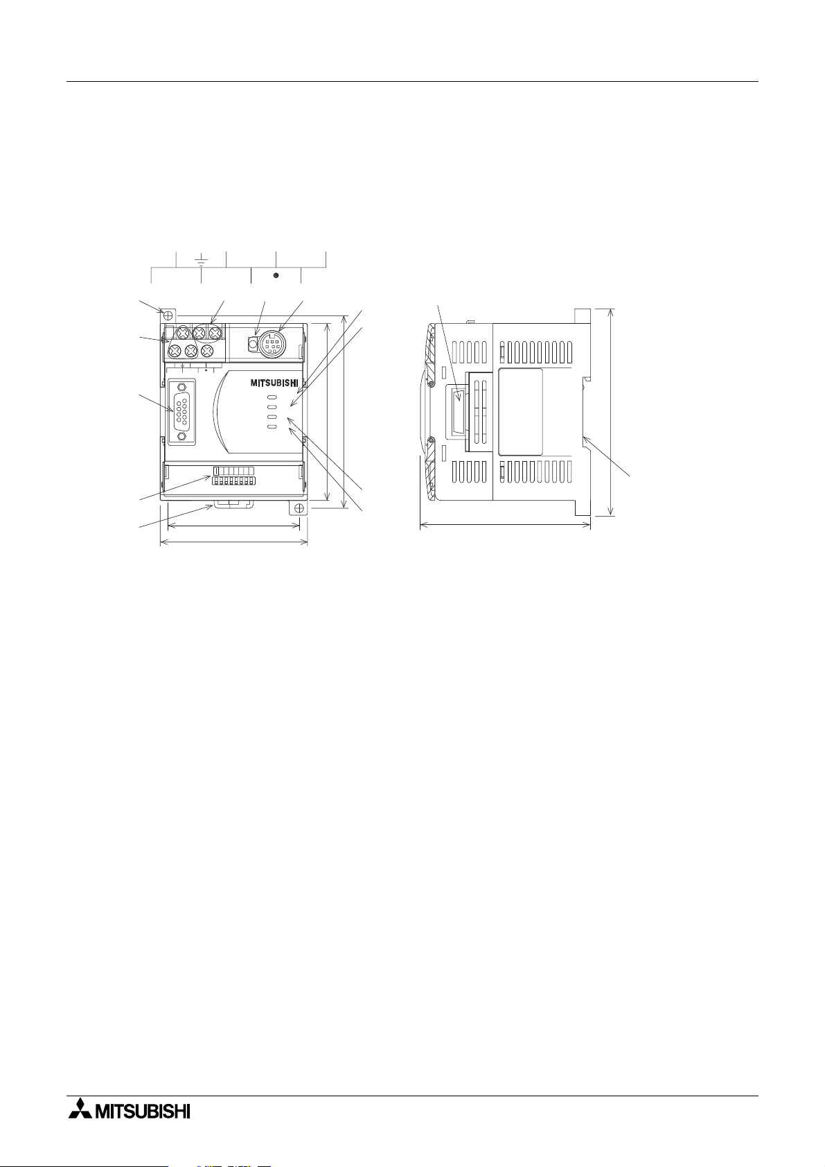
1.2 External Dimensions and Each Part Name
Dimensions: mm (inches) Weight: Approx. 0.4 kg (0.88 lbs)
Accessory: GSD files (FD: 1 piece)
Figure 1.1:External Dimensions
COM 24 +
L
c)
b)
L
N
e)
d)
RUN
STOP
24 +
COM
N
f )
g)
h)
m)
a)
l )
k)
2
4
6
3
6
1
67 (2.64")
75 (2.95")
FX2N -32DP -IF
1
2
4
8
POW ER
RUN
BF
DIA
ON
OFF
98 (3.86")
90 (3.54")
105 (4.13")
n)
i )
j )
87 (3.43")
a) Connector for Profibus cable (D-SUB 9 pin)
b) Power supply terminals (screws terminal: M3.5 (0.14"))
c) Direct mounting hole (2-φ4.5 (0.18"))
d) 24 V DC power terminal (screws terminal: M3.5 (0.14"))
e) RUN/STOP switch: When this switch is in the RUN position, the 32DP-IF will exchange
data with extension units/ blocks and special functio n blocks. If this
switch is in the STOP position, the 32DP-IF will exchange only input
data with extension units/blocks.
f) Communication port for FX-20P-E and personal computer
g) POWER LED : ON when AC power is supplied.
h) RUN LED : ON when 32DP-IF is exchanging data with extension units/blocks and
special function blocks.
i) BF LED : ON when a communication error is detected (No data exchange).
j) DIA LED : ON when notice of diagnostic data is detected.
k) Hook for mounting DIN rail
l) DIP switches for slave address of this unit
m)Connector for extension cable
n) Groove for mounting DIN rail (DIN rail width: 35 mm (1.38"))
1-2
Page 13
FX2N-32DP-IF Profibus-DP Interface Unit Introduction 1
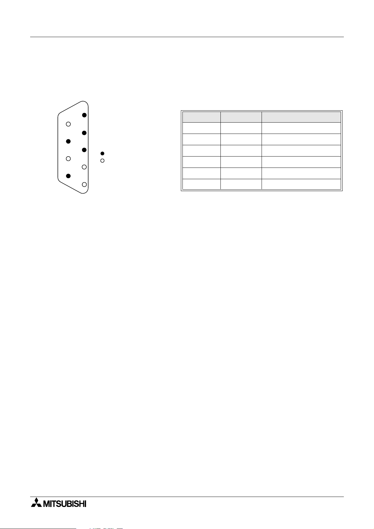
1.2.1 Pin Configuration
The connector is a 9-pin D-SUB type and the pin configurat ion i s shown below.
Figure 1.2:Pin Layout 9-pin D-SUB
Table 1.1: Pin Configuration
5
Connector Signal Meaning
4
8
3
79
Assigned
Not assigned
2
6
1
3
4
5
6
8
1,2,7,9
RXD/TXD-P Receive/transmit-Data-P(+)
RTS Request to send
DGND Data Ground
VP V oltage-Plus(+)
RXD/TXD-N Receive/transmit-Data-N(+)
NC Pin not assigned
1-3
Page 14
FX2N-32DP-IF Profibus-DP Interface Unit Introduction 1
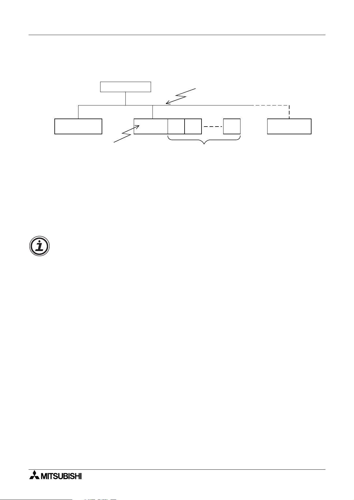
1.3 System Configuration
Figure 1.3:System Configuration
Profibus-DP network
Extension I/O units/blocks and
special function blocks *
3
Slave or
DP-master *
1
Slave or
DP-master *
FX2N-32DP-IF Profibus-DP
interface unit *
DP-master
1
2
*1 The units at each end of the Profibus-DP network must have a terminating resistor. This
will either be in the master or slave unit or in the Profibus connector.
*2 For connecting monitoring tool, refer to section 1.3.1
*3 For connecting extension I/O units/blocks and special function blocks, refer to section
1.3.2.
Caution
The parameter data of the 32DP-IF must be set correctly in the DP-mas ter, If the parameter
data are not correct, the operation of the module might be affected. For a detailed over view of
the parameter of 32DP-IF, refer to chapter 6.
1-4
Page 15
FX2N-32DP-IF Profibus-DP Interface Unit Introduction 1
1.3.1 Connected Programming Tools
An FX-20P-E or personal computer can be used to monitor the devices of the 32DP-IF or to
set parameter data for special function blocks connected to the 32DP-IF. For operating instructions of the FX-20P-E or personal computer, refer to their respective operation manuals. For
device n umbers and explanation, refe r to chapter 4.
Connecting cable is same as FX
Table 1.2:
FX-20P-E
Personal Computer
(MELSEC MEDOC PLUS)
Connected Programming Tools
Monitoring Tools Description
“Device Monitor”, “Data Change” and “Forced ON/OFF” in the Online
Monitor /Test mode can be used for supported devices.
“Device Edit” and “Entry Data Monitor” can be used for supported
devices.
/FX2N programmable cont roller.
0N
1-5
Page 16
FX2N-32DP-IF Profibus-DP Interface Unit Introduction 1
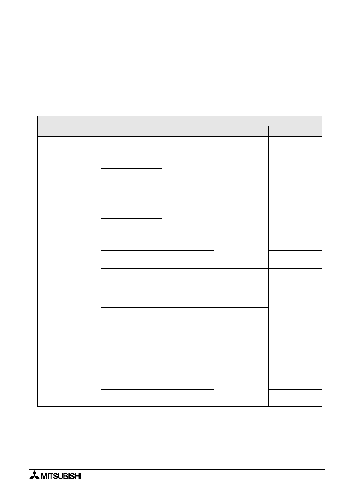
1.3.2 Connected Extension Units/Blocks
The table below shows extension units/blocks and their data lengths when connected to a
32DP-IF. Data is exchanged between the 32DP-IF and DP-master during every cycle. The
maximum amount of data that can be exchanged with the 32D P-IF is 200 bytes of input data
and 200 bytes of output data. Please check the specification of the DP-master, it may limit the
total amount of exchanged data.
Table 1.3: Connected Extension Units/Blocks and Exchanged Data Length
Exchange Data Length
Output Data (Y) Input Data (X)
Extension I/O Units
Items Description
2N
FX
-32ER-ES/UL
2N
FX
-32ET-ESS/UL
2N
FX
-48ER-ES/UL
2N
FX
-48ET-ESS/UL
Input = 16 points
Output = 16 points
Input = 24 points
Output = 24 points
2 Bytes (Y0 ~ Y17) 2 Bytes (X0 ~ X17 )
3 Bytes (Y0 ~ Y27) 3 Bytes (X0 ~ X27 )
Extension
I/O Blocks
2N
FX
Series
0N
FX
Series
2N
FX
-16EX-ES/UL
2N
FX
-16EYR-ES/UL
2N
-16EYT-ESS/UL
2N
FX
-16EYS-ES/UL
0N
-8EX-UA1/UL
FX
0N
FX
-8EX-ES/UL
0N
FX
-16EX-ES/UL
0N
-8ER-ES/UL
FX
0N
FX
-8EYR-ES/UL
0N
-8EYT-ESS/UL
FX
0N
FX
-16EYR-ES/UL
0N
FX
-16EYT-ESS/UL
2N
FX
-4DA
Input = 16 points
Output = 0 point
Input = 0 point
Output = 16 points
Input = 8 points
Output = 0 point
Input = 16 points
Output = 0 point
Input = 4 points
Output = 4 points
Input = 0 point
Output = 8 points
Input = 0 point
Output = 16 points
Digital to analog
converter
- 2 Bytes (X0 ~ X17)
2 Bytes (Y0 ~ Y17) -FX
1 Bytes (X0 ~ X7)
2 Bytes (X0 ~ X17)
1 Bytes (Y0 ~ Y3) 1 Bytes (X0 ~ X3)
1 Bytes (Y0 ~ Y7)
2 Bytes (Y0 ~ Y17)
-
8 Bytes,
Analog output data
(BFM #1 ~ #4)
Special Function
Blocks
*1 Total 8 by tes , selecti on between a veraged data (BFM #5 ~ #8) or present data (B FM #9 ~
#12) can be done by GSD file configuration for each channel separately.
2N
FX
-4AD
FX2N-4AD-PT
FX2N-4AD-TC
Analog to digital
converter
PT100 probe
interface
Thermo-couple
interface
8 Bytes
-
8 Bytes
8 Bytes
*1
*2
*3
1-6
Page 17
FX2N-32DP-IF Profibus-DP Interface Unit Introduction 1
*2 Total 8 bytes, selection between °C and °F, averaged or present data can be done by
GSD file configuration for each channel separately.
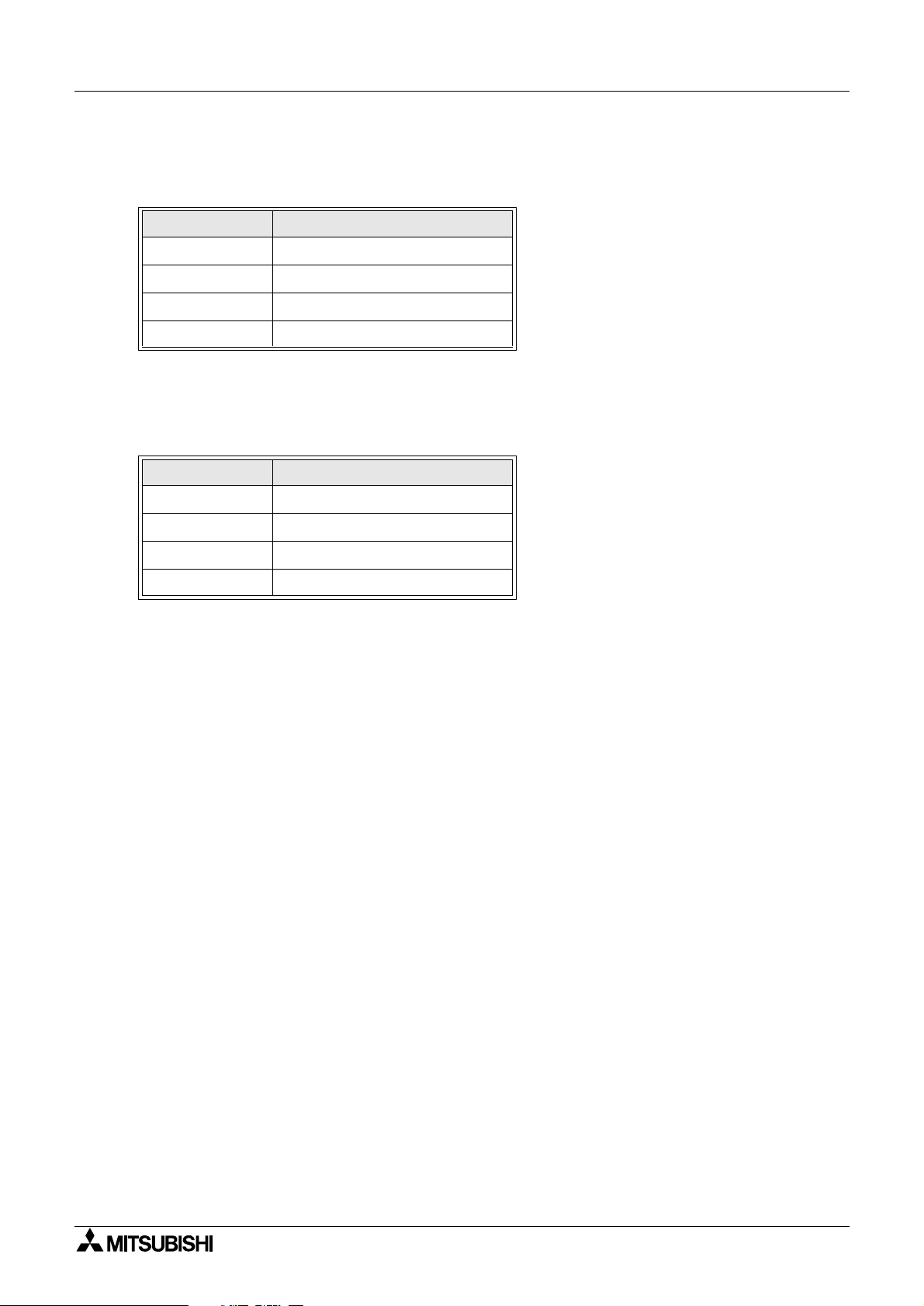
Table 1.4:BFM No. of FX2N-4AD-PT
Items BFM No.
°
C (averaged) BFM #5 ~ #8
°
C (present) BFM #9 ~ #12
°
F (averaged) BFM #13 ~ #16
°
F (present) BFM #17 ~ #20
*3 Total 8 bytes, selection between °C and °F, averaged or present data and the type of
thermocouple can be done by GSD file configuration for each channel separately.
Table 1.5:BFM No. of FX2N-4AD-TC
Items BFM No.
°
C (averaged) BFM #5 ~ #8
°
C (present) BFM #9 ~ #12
°
F (averaged) BFM #13 ~ #16
°
F (present) BFM #17 ~ #20
1-7
Page 18
FX2N-32DP-IF Profibus-DP Interface Unit Introduction 1
1.3.3 Configuration Rules
1) Special function blocks: Max. 8 blocks per 32DP-IF.
Check the loading on the 5 V DC bus supply. Consumption values for special function
blocks can be found in Tabl e 1.7. For maximum av ailable current see the Table 1.6.
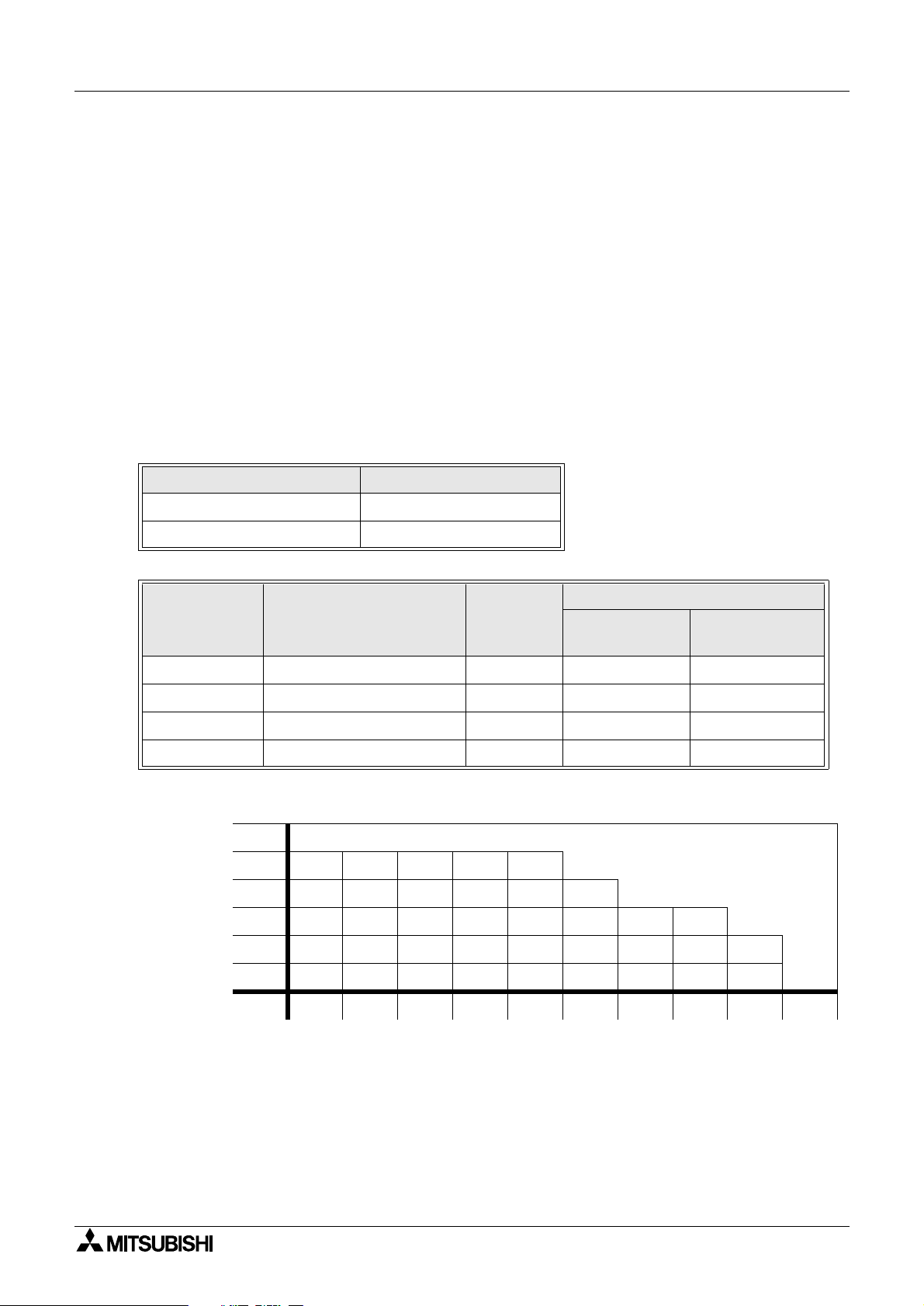
2) Maximum I/O points: 256 or less.
3) Check the loading on the 24 V DC service supply. Look up the number of expansion I/O in
Figure 1.4. Find the residual current. This can then be used to power sensors etc.
4) Check total exchanged data length in DP-master, this number might be limited by the DPmaster unit. Data length is exchanged between the 32DP-IF and a DP-master in every
cycle.
For the data length of connected extension units/blocks, refer to Table 1.3.
Howe ver, the maximum amount of data tha t can be exchanged with the 32DP-IF is 200 byte
inputs and 200 byte outputs.
Table 1.6:24 and 5 V DC Supply Capacity
Items Power Supply
24 V DC Service Supply 500 mA at 24 V DC
Max. 5 V DC Bus Supply 220 mA at 5 V DC
Table 1.7:Power Supply for Special Function Blocks
Model Description
2N
FX
-4DA Digital to analog converter 8 30 200
2N
FX
-4AD Analog to digital converter 8 30 55
2N
FX
-4AD-PT PT100 probe interface 8 30 50
2N
FX
-4AD-TC Thermo-couple interface 8 30 50
Number of
I/O Points
Internal 5 V DC
Power Supply
(mA)
External 24 V DC
(mA)
Figure 1.4:Number of Expansion I/O and 24 V DC Service Supply Capacity (mA)
> 32
Number of
additional
output
(points)
32 200 150 100 50 0
24 275 225 175 125 75 25
16 350 300 250 200 150 100 50 0
8 425 375 325 275 225 175 125 75 25
0 500 450 400 350 300 250 200 150 100
Invalid configuration
0 8 16 24 32 40 48 56 64 > 64
Number of additional input (points)
For extension unit, refe r to FX2N Series Hardware Manual.
1-8
Page 19
FX2N-32DP-IF Profibus-DP Interface Unit Introduction 1
1.3.4 Example Configuration
Figure 1.5:Example Configuration
A Series
PLC
Profibus-DP
network
A1SJ71PB92 (software version E)
FX2N-
32DP-IF
FX2N-16EX
-ES/UL
FX2N-16EYT
-ESS/UL
FX2N-
4AD
FX2N-
4DA
FX2N-
4DA
For configuration rules, refer to section 1.3.3.
1) Check special function blocks.
a) Count special function blocks.
This 32DP-IF has 3 special function blocks connected (FX
-4AD × 1, FX2N-4DA × 2).
2N
This configuration is OK as the total number of blocks is less than 8.
b) Check the loading on the 5 V DC bus supply. Consumption values for special function
blocks can be found in Table 1.7. For maximum available current see the Table 1.6.
Table 1.8:Check 5 V DC Bus Supply
Items Internal 5 V DC External 24 V DC
2N
FX
-4AD 30 mA 55 mA
2N
FX
-4DA 30 mA 200 mA
2N
FX
-4DA 30 mA 200 mA
Total Consumption Values 90 mA <220 mA 455 mA
This configuration is OK as the 5 V DC bus supply consumption value is less than 220 mA
(5 V DC bus supply capacity).
Howe ver, this syste m needs a supply of 455 mA from an external 24 V DC power supply, for
the special function blocks. In this case, the 32DP-IF can supply 250 mA for external 24 V
DC. See next page (check the loading on the 24 V DC service supply)
1-9
Page 20
FX2N-32DP-IF Profibus-DP Interface Unit Introduction 1
2) Check total I/O poi nts and the lo adin g on th e 24 V DC service supply. For the loading on the
24 V DC service supply, refer to Figurer 1.4.
Table 1.9:Check Total I/O Points and the Loading on the 24 V DC Service Supply
Addressable I/O 24 V DC Service Supply
Units/Block Name
Inputs
(X)
Outputs
(Y)
Function
Blocks
Sum I/O Sum
(X/Y)
Special
2N
-32DP-IF 0 0 -
FX
2N
FX
-16EX-ES/UL 16 0 -
2N
FX
-16EYT-ESS/UL 0 16 -
2N
FX
-4AD - - 8 - 0 mA
2N
FX
-4DA - - 8 - 0 mA
2N
FX
-4DA - - 8 - 0 mA
16 16 24
Total I/O is 56 points <256 points
Inputs (X) = 16
Outputs (Y) = 16
According to Figure 1.4
This configuration can supply 250 mA at
24 V DC service supply for other usages.
+ 250 mA
This configuration is OK as the total I/ O points are less than 256. It is also OK with the load ing on the 24 V DC service supply, this configuration can supply 25 0 mA at 24 V DC service
supply for other usages.
3) Check the total allowable exchanged data length for each input data and output data in the
DP-master, because this number might be limited by the DP-master unit.
Maximum exchanged data length of 32DP-IF can be found in Table 3.3. For the data length
of connected extension units/blocks, refer to Table 1.3.
Table 1.10:Check Total Exchanged Data Length
Units/Blocks Name
2N
FX
-16EX-ES/UL 2 bytes 0 byte
2N
FX
-16EYT-ESS/UL 0 byte 2 bytes
2N
FX
-4AD 8 bytes 0 byte
2N
FX
-4DA 0 byte 8 bytes
2N
FX
-4DA 0 byte 8 bytes
Total exchanged data length
10 bytes < 200 bytes
<244 bytes
Exchanged Data Length
Input Data Output Data
*1
18 bytes < 200 bytes *1
*2
<244 bytes
*2
*1 This value is maximum exchanged data length of 32DF-IF.
*2 This example configuration use A series programmable controllers A1SJ71PB92D (soft-
ware version is E). This DP-master is limited to 244 bytes of input data and 244 bytes of
output data.
This configuration is OK as t he ea ch total input dat a and tot al out put data leng th is les s than
200 bytes.
1-10
Page 21
FX2N-32DP-IF Profibus-DP Interface Unit
2. Wiring and Mounting Arrangements
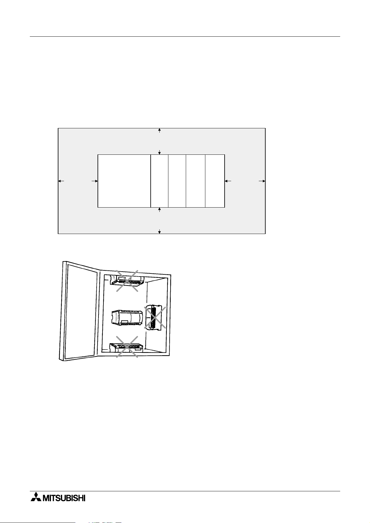
2.1 Mounting Arrangements
To prevent a rise in temperature, mount the units to back walls. Never mount them to the floor,
ceiling or side wall of an enclosure.
Figure 2.1:Mounting Location
> 50 mm
(1.97")
Wiring and Mounting Arrangements 2
> 50 mm
(1.97")
FX2N-32DP-IF
-4DA
2N
FX
> 50 mm
(1.97")
Figure 2.2:Mounting Arrangement
-4AD
2N
FX
-16EX
2N
-ES/UL
FX
-16EYT
2N
-ESS/UL
FX
> 50 mm
(1.97")
2-1
Page 22

FX2N-32DP-IF Profibus-DP Interface Unit Wiring and Mounting Arrangements 2
2.2 Wiring
2.2.1 Caution for Wiring
1) Do not lay signal cable near to high vol tage po wer cab le or house t hem in the same trunking
duct. Effects of noise or surge induction may occur. Keep signal cables a safe distance of
more than 100 mm (3.94") from these power cables.
2) Ground the shied wire or the shield of a shielded cable at one point on the programmable
controller. Do not, however, ground at the same point as high voltage lines.
3) The terminal screws of the 3 2DP-I F are M3. 5 ( 0.1 4"), therefore the crimp style terminal (see
drawing) suitable for use with these screws should be fitted to the cable for wiring.
Figure 2.3:Crimp Terminals
6.8 mm (0.27" )
or less
For M3.5 (0.14")
6.8 mm (0.27")
or less
For M3.5 (0.14")
4) The terminal tightening torque is 0.5 to 0.8 N•m. Tighten securely to avoid malfunction.
5) Cut off all phases of power source before installation or performing wiring work in order to
avoid electric shock or damage of product.
6) Replace the provided terminal cover before supplying power and operating the unit after
installation or wiring work, in order to avoid electric shock.
2-2
Page 23

FX2N-32DP-IF Profibus-DP Interface Unit Wiring and Mounting Arrangements 2
2.2.2 Wiring for 32DP-IF and Profibus-DP Network
To connect the 32DP-IF to a Profibus-DP network use only the Profibus connectors and
shielded twisted-pair cable complying with EN50170.
Please use terminating resistors and Profibus connectors as shown in the DP-master manual
and Profibus connector manual.
The 32DP-IF does not have a terminating resi stance built-in.
Figure 2.4:Wiring about 32DP-IF and Profibus-DP Network
For Profibus
connector, refer
to Figure 2.6.
100 ~ 240 V AC
For power circuit,
refer to Figure 2.5.
Shielded twisted-pair
cable complying with
Power line
circuit
Service supply
EN50170 to Profibus-
L COM24+
DP network
N
Grounding plate
Grounding
resistance of
or less
100
Ω
(Class 3)
Figure 2.5:Wiring for Power Line Circuit
100 ~ 240 V AC
MC
MC
Connect to "N" terminals
FX
-32DP-IF
2N
Profibus-DP
Interface Unit
For noise prevention please attach at least 50 mm
(1.97") of the twisted-pai r cable along the grounding
plate to which the ground terminal is connected.
Emergency stopCircuit protection device
Power supply
MC
for loads
Fuse
MC
Power supply
for loads
Connect to "L" terminals
Figure 2.6:Profibus Connector
Shielded twisted-pair cable to
Profibus-DP network
-32DP-IF Profibus
FX
2N
Interface-DP Unit
2-3
Page 24

FX2N-32DP-IF Profibus-DP Interface Unit Wiring and Mounting Arrangements 2
2.2.3 Wiring for Extension I/O Units/Bloc ks and Special Function Blocks
1) Wiring about 32DP-IF and special function bloc k
Connecting method is same as FX
sires programmable controller. For special function
2N
block’s wiring, refer to each user’s manual.
2) Wiring about 32DP-IF and Extension Unit
Connect “COM” terminal at the 32DP-IF t o “0V” t erminal at the extension unit. F or extension
unit’s wiring, refer to FX
Series Hardware Manual.
2N
3) Wiring about 32DP-IF and Extension Block
The wiring method for the “S/S” t erminal on the extension block s is sh o wn i n the Fi gures 2. 7
and 2.8.
For extension block’s wiring and special function block’s wiring, refer to each manual.
Figure 2.7:Source (positive input connection, negative S/S)
PNP
24+
FX
-32DP-IF Profibus-DP
2N
Interface Unit
COM
S/S X0 X1 X2
Ex. FX2N-16EX-ES/UL
Figure 2.8:Sink (negative input connection, positive S/S)
NPN
24+
FX
-32DP-IF Profibus-DP
2N
Interface Unit
COM
S/S X0 X1 X2
Ex. FX2N-16EX-ES/UL
2-4
Page 25

FX2N-32DP-IF Profibus-DP Interface Unit
3. Specifications
3.1 General Specifications
Table 3.1:General Specifications
Item Description
Operating Temperature 0 to 55 °C (32 to 131 °F)
Storag e Temperature -20 to 70 °C (-4 to 158 °F)
Operating Humidity 35 to 85% Relative Humidity, No condensation
Storage Humidity 35 to 90% Relative Humidity, No condensation
Specifications 3
Vibration Resistance
- Direct Mounting
Vibration Resistance
- DIN rail Mounting
Shock Resistance
Noise Immunity 1,000 Vp-p, 1microsecond, 30 - 100 Hz, tested by noise simulator
Dielectric Withstand Voltage 1,500 V AC > 1 min, tested between all points, terminals and ground
Insulation Resistance 5 MΩ > at 500 V DC, tested between all points, terminals and ground
Grounding Class 3 (Grounding resistance is 100 Ω or less)
Planned Certifications CE
Conforms to JIS C0040; 10 - 57 Hz: 0.75 mm Half Amplitude
57 - 150 Hz: 9.8 m/s
Sweep Count for X, Y, Z: 10 times (80 min in each direction)
Conforms to JIS C0040; 10 - 57 Hz: 0.035 mm Half Amplitude
57 - 150 Hz: 4.9 m/s
Sweep Count for X, Y, Z: 10 times (80 min in each direction)
Conforms to JIS C0041: 147m/s
3 times in each direction X, Y, and Z
3.2 Power Supply Specifications
Table 3.2:Power Supply Specifications
Item Description
Power Supply 100 ~ 240 V AC +10% -15%, 50/60 Hz
2
Acceleration
2
Acceleration
2
Acceleration, Action Time: 11 ms
Max. Allowable Momentary
Power Failure Period
Fuse (size) Rating 3 A <φ 5 × 20 mm (0.2 × 0.79 inches)>
In-rush Current 100 V AC Max. 40 A < 5 ms, 200 V AC Max. 60 A < 5 ms
Power Consumption 35 VA
24 V DC Service Supply 500 mA
Max. 5 V DC Bus Supply 220 mA
10 ms at 100 V AC
(< 10 ms, 32DP-IF = RUN continue, > 10 ms, 32DP-IF = power down)
3-1
Page 26

FX2N-32DP-IF Profibus-DP Interface Unit Specifications 3
3.3 P erformance Specifica ti ons
Table 3.3:Performance Specifications
Items Specifications
Maximum Number of Controllable
I/O Points
Transmission data
(Maximum exchanged data length)
Transmission Type Bus network
9 pin D-SUB Connector for Profibus-DP network
Connector
Supported Baud
Rates and Bus
Length (bps)
LED Indicators
8 pin mini DIN
9.6k, 19.2k,
45.45k, 93.75k
187.5k 1,000 m (3,281')
500k 400 m (1,312')
1.5M 200 m (656')
3M, 6M, 12M 100 m (328')
POWER LED ON when AC power is supplied.
RUN LED
BF LED ON when a communication error is detected. (No data exchange)
Maximum 256 points (see section 1.3)
400bytes can be sent and received during one bus cycle.
(input: 200 bytes, output: 200 bytes)
Connector for FX-20P-E or personal computer (MELSEC
MEDOC PLUS)
1,200 m (3,937')
ON when 32DP-IF is exchanging data with extension I/O blocks/
units and special function blocks.
DIA LED ON when notice of diagnostic data is detected.
3-2
Page 27

FX2N-32DP-IF Profibus-DP Interface Unit
4. Advanced Devices
4.1 Data Registers
Table 4.1:Supported Data Register List
Items Description
D0 ~ D99
D100 ~ D199
D200 ~ D299
*1 If the 32DP-IF is in data exch ange mode , the sent dat a to a DP-master can be moni tored
by reading data registers D0 ~ D99 in the programming tool.
For example of allocating device, refer to section 4.1.1.
*2 If the 32DP-IF is in data exchange mode, the received data from a DP-master can be
monitored by reading data registers D100 ~ D199 in the programming tool.
For example of allocating device, refer to section 4.1.1.
Input (sent) data to DP-master
Output (received) data from DP-master
Parameter data
Advanced Devices 4
*1
*2
*3
*3 The data registers D200 to D299 contain the user parameter data which sent by the DP-
master. After power on, when the 32DP-IF is in the search baud rate state or the wait
parameter state, these data register contain the default parameter data.
For user parameter, refer to chapter 6. For default parameter settings, refer to appendix
A.
4-1
Page 28

FX2N-32DP-IF Profibus-DP Interface Unit Advanced Devices 4
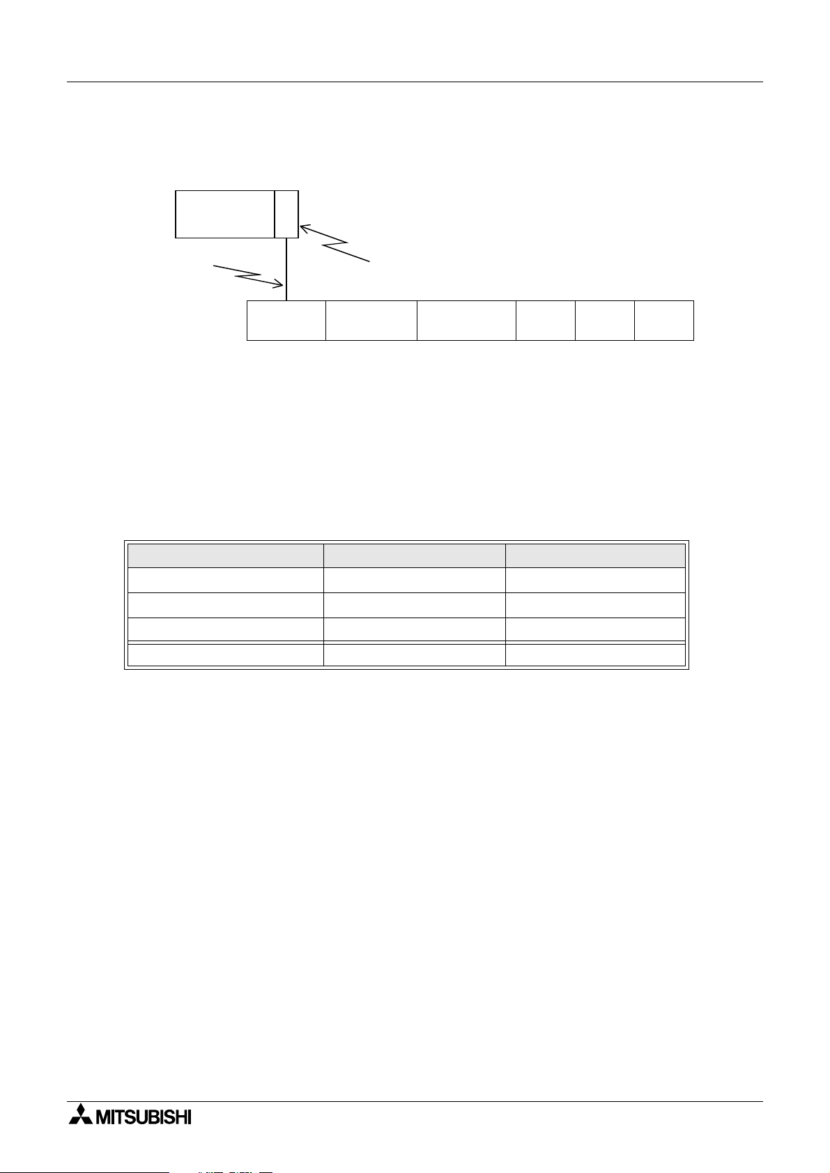
4.1.1 Example of Allocating Device
Figure 4.1:Example of Allocating Device
FX2N-
32DP-IF
X0 ~ X3
Y0 ~ Y3
FX0N-8ER
-ES/UL
X10 ~ X27
FX2N-16EX
-ES/UL
Using Ch1 ~ Ch4
(average data)
FX2N-4AD
Table 4.2:Example of Allocating Device
Device No. Description
D0 to D3 FX
Lower 8 bits FX
D4
Higher 8 bits FX
Lower 8 bits FX
D5
Higher 8 bits
D6 ~ D99
D100 ~ D103 FX
Lower 8 bits FX
D104
Higher 8 bits FX
D105 ~ D199 These devices are not used.
2N
-4AD’s input data (BFM #5 ~ #8)
0N
-8ER-ES/UL’s X0 ~ X3 (bit 4 ~ 7 not used)
2N
-16EX-ES/UL’s X10 ~ X17
2N
-16EX-ES/UL’s X20 ~ X27
These devises area not used.
2N
-4DA’s output data (BFM #1 ~ #4)
0N
-8ER-ES/UL’s Y0 ~ Y3 (bit 4 ~ 7 not used)
0N
-8EYT-ESS/UL’s Y10 ~ Y17
Using Ch1 ~ Ch4
FX2N-4DA
Y10 ~ Y17
FX0N-8EYT
-ESS/UL
Note:
In configuring 32DP-IF GSD file, first assign special function blocks, second extension I/O
units/blocks’ input data, and finally extension I/O units/blocks’ output data. The physical
placement of the module does not have to correspond with the GSD file order.
4-2
Page 29

FX2N-32DP-IF Profibus-DP Interface Unit Advanced Devices 4
4.2 Diagnostic Devices (Special Devices) Unsettable Devices:
Any de vic e of typ e M or D t hat i s marked wi th a “()” or “()” cannot be set b y the pr og r amming tool. In the case of M devices this means the associated coil cannot be driven but all
device can be monitored. For data devices D, new values cannot be written to the register
by a user but the register contents can be monitored.
Symbol Summary:
• automatically written to by the 32DP-IF
automatically written to by the DP-master
•
•
32DP-IF send an extended diagnosis message to DP-master if marking device is ON.
For diagnostic massage, refer to chapter 7.
4-3
Page 30

FX2N-32DP-IF Profibus-DP Interface Unit Advanced Devices 4
4.2.1 32DP-IF Status (M8000 ~ M8009 and D8000 ~ D8009)
Table 4.3:Special Auxiliary Relays (M8000 ~ M8009)
Diagnostic
Device
M8000
M8001 ~ M8003 Reserved
()
Name Description
ON when 32DP-IF is exchanging data with extension I/O
RUN LED monitor
blocks/units and special. This device operate same as RUN
LED.
M8004
(ref. D8004)
M8005, M8006 Reser ved
M8007
(ref. D8007)
M8008, M8009 Reser ved
()
() ()
Error occurrence
Momentary
power failure
ON when one or more error flags (M8060 to M8068) is ON. If
this bit is ON, error number is written in D8004.
See Figure 4.2.
Table 4.4:Special Data Registers (D8000 ~ D8009)
Diagnostic
Device
D8000 Reserved
D8001
D8002, D8003 Reserved
D8004
D8005, D8006 Reserved
D8007
()
() ()
() ()
Name Description
32DP-IF version This value is 32DP-IF version code. See Figure 4.3.
Error numb er
M
Number of
momentary
power failures
The contents of this register
is active, i.e. if
This value is counted when M8007 is ON. This value is reset
on full power OFF.
= 8061, identifies M8061
identifies which error flag
D8008
D8009 Reserved
()
Power failure
detection period
Power failure detection period is 10 ms.
Figure 4.2:Momentary Power failures
AC Power
Exchanged
with DP-master
M8007
10 ms
5 ms
Momentary power failure
Figure 4.3:32DP-IF Version
dec
Version No.: Ex. 100 = V1.00
Module Type No.: Ex. 20 = 32DP-IF
This time is power failure detection per iod.
4-4
Page 31

FX2N-32DP-IF Profibus-DP Interface Unit Advanced Devices 4
4.2.2 Profibus-DP Network Status (M8020 ~ M8039 and D8020 ~ D8039)
Table 4.5:Special Auxiliary Relays (M8020 ~ M8039)
Diagnostic
Device
M8020 Setting parameter
M8021 ~ M8033 Reserved
M8034 All output disable
M8035 ~ M8039 Reserved
Name Description
When this bit is changed from OFF to ON, the parameter D200
~ D299 (made by the programming tool) is written to special
function blocks’ BFM. After the write is completed, this bit is
turned automatically to OFF.
All physical switch gear for activating outputs is disabled. However, for debugging purposes the logical state of these outputs
(D100 ~ D199) can be set, but remain disabled in the actual
module.
Table 4.6:Special Data Registers (D8020 ~ D8039)
Diagnostic
Device
Name Description
D8020
D8021
D8022
D8023
D8024
D8025
D8026
D8027
D8028 Reserved
()
()
()
()
()
()
()
()
Data exchange
status
Swap byte order See note 1.
Length of input
(sent) data in byte
Length of output
(received) data in
byte
Baud rate See note 2.
Communication
status
Profibus module
ID (PNO ID code)
Slave address
Data register D8020 contains a status bit for data exchange.
If this is “1”, 32DP-IF is in data exchange mode.
If this is “0”, 32DP-IF is not in data exchange mode.
The values held in these devices are copied from the input data
length and output data length setting in the DP-master.
See note 3.
PNO-Nr.F232 (Hex )
(This number contains the Profibus module ID number for the
32DP-IF.)
The slave address is set only by the 32DP-IF’s DIP s witches.
The slave address value is 0 to 126. The address change by a
Profibus-DP Class 2 master via the network or by a programming device is not supported.
D8029
() ()
Error status See note 4.
Note 1: Swap byte order
Some DP-masters handle lower bytes and higher bytes of a word in a reverse order than the 32DPIF. T o enab le the module to communicate with these masters, bit 0 of data register D8021 can be set.
If bit 0 is “1”, the low order byte and the high order byte of each user data word and of the user specific diagnosis will be swapped. Bit 0 of D8021 can also be set or reset by the second user defined
parameter byte received from a master. The default value after power up is “0”.
4-5
Page 32

FX2N-32DP-IF Profibus-DP Interface Unit Advanced Devices 4
Note 2: Baud rate
This device shows the current baud rate of the Profibus-DP network. The baud rate depends on the
DP-master settings. The following table shows the supported baud rates and the value of D8024. If
the module is in baud search mode, this value frequently changes until the module has found a supported baud rate as follows.
Table 4.7:Baud Rate in D8024
Values in D8024
(Hex)
96E2 H 9,600 05E5 H 500k
19E3 H 19.2k 15E5 H 1.5M
45E3 H 45.45k 03E6 H 3M
93E3 H 93.75k 06E6 H 6M
18E4 H 187.5k 12E6 H 12M
Baud Rate (bps)
Values in D8024
(Hex)
Baud Rate (bps)
4-6
Page 33

FX2N-32DP-IF Profibus-DP Interface Unit Advanced Devices 4
Note 3: Communication status
This device is the 32DP-IF’s communication status. According to the status of 32DP-IF the
bits are set and reset as follows.
Table 4.8: Communication Status in D8025
Bit No. Description 1 (ON) 0 (OFF)
Bit 0 Module on-line/off-line Module on-line Module off-line
Bit 1 Reserved
BIt 2 Diagnosis flag
Bit 3 Reserved
Bit 4, 5 DP-status
Bit 6, 7 DP-watchdog state
Bit 8 Reserved
BIt 9
Bit 10
Bit 11
Bit 12
Bit 13
Clear data global control
Unfreeze global control
Freeze global control
Unsync global control
Sync global control
New diagnosis not yet fetched by
DP-master
New diagnosis fetched by
DP-master
(bit 5, 4) = (0, 0) Wait parameter state
(bit 5, 4) = (0, 1) Wait configuration state
(bit 5, 4) = (1, 0) Data exchange state
(bit 5, 4) = (1, 1) Not possible
(bit 7, 6) = (0, 0) Baud search state
(bit 7, 6) = (0, 1) Baud control state
(bit 7, 6) = (1, 0) DP search state
(bit 7, 6) = (1, 1) Not possible
*1
Clear data command received No clear data command received
*2
Unfreeze command received No unfreeze command received
*3
Freeze command received No freeze command received
*4
Unsync command received No unsync command received
*5
Sync command received No sync command received
Bit 14, 15 Reserved
*1 Clear data global control: When this command is received, the 32DP-IF set to “0” the output
*2 Unfreeze global control: The UNFREEZE control command stops freeze control mode. The
*3 Freeze global control: The DP-master sends a FREEZE control command to a group of DP-
*4 Unsync global control: The UNSYNC command stops SYNC contro l mode. The output da ta
*5 Sync global control: The DP-master sends a SYNC control com mand to a group of DP-
data (D100 ~ D199) of extension units/blocks connected it.
input data (D0 ~ D99) of extension units/blocks connected to the
32DP-IF is immediately sent to the DP-master.
slaves to hold their curre nt input s tatus. The input da ta (D0 ~ D9 9) of
extension units/blocks connected to the 32DP-IF are withheld until
the next FREEZE/UNFREEZE control command is received.
(D100 ~ D199) send from the DP-master is immediately transmitted
to extension units/blocks connected to the 32DP-IF.
slaves to synchro nize their current ou tput states. Th e output data
(D100 ~ D199) of extension units/blocks connected to the 32DP-IF
remains constant until the next SYNC/UNSYNC command is
received.
4-7
Page 34

FX2N-32DP-IF Profibus-DP Interface Unit Advanced Devices 4
Note 4: Error status
Data register D8029 reflects t he error st atus of t he 32DP-IF. In case of a general error (bit 0
= ON) the module tries to send a static diagnosis to the DP-master. In this case normal data
exchange is not possible. If bit 0 returns to the Off state, the static diagnosis me ssage is
also reset.
The definition of the error bit is shown in the table below.
Table 4.9:Error status in D8029
Bit No. Description 0 (OFF) 1 (ON)
Bit 0 general error No general error
Bit 1 Reserved
Bit 2
Bit 3 ~ 5 Reserved
Bit 6
(ref. Table
4.11)
Bit 7
(ref. Table
4.11)
Bit 8, 9 Reserved
Bit 10
(ref. Table
4.11)
Bit 11
(ref. Table
4.11)
External 24 V po wer
error
I/O bus error No I/O bus error
Operation error No operation error
configuration error
Parameter error
Power supply is
normal
Configuration
data valid
Parameter data
valid
This bit is ON if one or more error bits (bit 2, 6,
7) are ON. Check Bit 2, 6 and 7 in D8029.
DC 24 V power supply failure
I/O bus error occurred. Check extension bus
cable for I/O extension units/blocks and error
code in D8060.
Operation error occurred. Check extension bus
cable for special function blocks, and DP-master parameter, and error code in D8067 and
D8068.
Invalid configuration data received. Check configuration for 32DP-IF in the DP-master and
D8040 ~ D8055.
Invalid parameter data received. Check parameter for 32DP-IF in the DP-master and D200 ~
D299, and error code in D8064and D8068.
Bit 12 ~ 14 Reserved
Bit 15 RUN/STOP status
RUN/STOP
switch is in RUN
position
RUN/STOP switch is in STOP position
4-8
Page 35

FX2N-32DP-IF Profibus-DP Interface Unit Advanced Devices 4
4.2.3 Configuration Status (M8040 ~ M8059 and D8040 ~ D8059)
M8040 ~ M8059 are reserved. The conf igur at ion b yt es i n D8 040 ~ D8059 d efi ne the a mount of
data which is exchanged between the corresponding I/O units/blocks, special function blocks
and the DP-master.
Table 4.10:Special Data Registers (D8040 ~ D8059)
Diagnostic Device Name Description
*1
*1
*1
The data registers D8040~D8055 display the
*1
actual configuration of the node station. After
*1
power on, when the 32DP-IF is in the search
baud rate state or in the wait configuration
*1
state, these data registers contain the default
configuration data.
*1
*1
D8040 (
D8041 ()
D8042 ()
D8055 (
Lower 8 bits
)
Higher 8bits
Lower 8 bits
Higher 8bits
Lower 8 bits
Higher 8bits
:
:
Lower 8 bits
)
Higher 8bits
Configuration data 1
Configuration data 2
Configuration data 3
Configuration data 4
Configuration data 5
Configuration data 6
:
:
Configuration data 31
Configuration data 32
D8056 ~ D8059 Reserved
*1 This value shows as following Figure.
Ex.1 10 hex = 1 byte (8 bit) inputs not consistent
Ex.2 63 hex = 4 word outputs not consistent
Figure 4.4:Configuration Data
bit 7
bit 0
Length of data
00 = 1 byte/word
:
:
15 = 16 byte/word
Input/output
00 = Special format
01 = Input
10 = Output
11 = Input and output
Byte/Word
0 = Byte
1 = Word
Consistency
0 = Consistency of byte/word
1 = Consistency of entir length
4-9
Page 36

FX2N-32DP-IF Profibus-DP Interface Unit Advanced Devices 4
4.2.4 Error Status (M8060 ~ M8069 and D8060 ~ D8069)
Table 4.11:Special Auxiliary Relays (M8060 ~ M8069)
Diagnostic
Device
Name Check Points
M8060
(ref. D8060,
D8061)
M8061
(ref. D8060,
D8061)
M8062, M8063 Reser ved
M8064
(ref. D8064
M8065, M8066 Reser ved
M8067
(ref. D8067)
M8068
(ref. D8068)
M8069 Reserved
() ()
() ()
() ()
() ()
()
I/O configuration error
32DP-IF hardware error If this bit is ON, check error code in D8061.
Parameter error
Operation error
Parameter error and operation
error
If this flag is ON, check error code in D8060,
D8061 and extension cable.
If this flag is ON , check error c ode inD80 64 and
DP-master setting.
If this flag is ON, check error code in D8067 and
D8068, DP-master parameter, and the extension
cable.
If M8064 or M8067 is ON, this bit would be set to
ON. This bit is cleared by resetting the power
supply.
4-10
Page 37

FX2N-32DP-IF Profibus-DP Interface Unit Advanced Devices 4
Table 4.12:Special Data Registers (D8060 ~ D8069)
Diagnostic
Device
Name
Error
code
Description
D8060 (
D8061 (
D8062, D8063 Reserved
D8064 (
D8065,D8066 Reserved
D8067 (
)
error
32DP-IF hard-
()
)
ware error
Parameter error
()
)
Operation error
()
)
I/O configuration
()
This device contains the lowest device address that caused the
error. Check D8061
0 No error
6102
6103
6129
6406
6407
6708
Operation circuit error: Please contact a service representative.
I/O bus error: Check extension cable for Extension I/O
units/blocks.
BFM #29 (error status) of a connected special function
block shows a value that is different from “0 ”. Please
check the diagnosis message at the DP-master.
0 No error
Parameter error for extension units/blocks: Check error
code in D8068, and parameter in the DP-master.
Parameter length error: Parameter data too long, check
parameter’s length in the DP-master.
0 No error
Operation error: Operation error for transmitting special
function block is occurred, check error code in D8068, and
DP-master parameter, and extension cable.
Parameter error
and operation
()
D8068 (
D8069 Reserved
)
error
This device contains the lowest special function block’s address
that caused the error. Check D8064 and D8067.
4-11
Page 38

FX2N-32DP-IF Profibus-DP Interface Unit Advanced Devices 4
4-12
Page 39

FX2N-32DP-IF Profibus-DP Interface Unit
5. Address Setting
5.1 Setting Address
Slave address of 32DP-IF for Profibus network is set by the ON/OFF configuration of DIP
switches. Slave address setting range is 0 ~ 126. When 32DP-IF’s power supply is turned ON,
the slave address is the sum total of these DIP switch values.DIP Switches
643216
Address Setting 5
8
4
2
1
This is DIP switch value.
ON
This DIP switch is not
used for the address
setting. Please leave in
the OFF position.
Note:
If the address of 32DP-IF is changed, the 32DP-IF must be turned OFF and ON again in
order to activate the new address.
5.2 Example Address Setting
If slave address of 32DP-IF is set to “22”, DIP switches are as shown below.
Figure 5.1:Address Setting
8
4
2
643216
1
ON
OFF
These DIP
switches are OFF.
OFF
This DIP switch is ON.
5-1
Page 40

FX2N-32DP-IF Profibus-DP Interface Unit Address Setting 5
5-2
Page 41

FX2N-32DP-IF Profibus-DP Interface Unit
6. User Parameter
6.1 User Parameter Rules
Some bytes of input data and output data exchanged with the DP-master (the 32DP-IF’s configuration) must be defined by user parameter. Also defined by user parameters are how the
exchanged data should be distributed between the available I/O points and special function
blocks. Some applications require initial settings, like gain and offset of analog blocks. For
these purposes, the 32DP-IF requ ires a set of parameter da ta, which must be deter mine d by
the user parameter.
For “afte r power on” parameter, refer appendix A. For user parameter example, refer to appendix B.
Note:
User parameters become valid for 32DP-IF and special function blocks (ex. FX2N-4AD, FX2N4DA).
Table 6.1:User Parameter Configuration
User paramete r
for 32DP-IF
User paramete r
for first special
function block
User paramete r
for second special
function block
1 + (2 + m
Byte No.
0
1
2
:
:
1 + (2 + m
1 + (2 + m
:
:
1
*1) + (2 +m2 *1)
User Parameter 6
*1
1
)
*1
1
) +1
:
:
, m2: Total length of parameter data for this special function b lock.
*1 m
1
:
:
6-1
Page 42

FX2N-32DP-IF Profibus-DP Interface Unit User Parameter 6
Figure 6.1: User Parameter Rules
For 32DP-IF
Byte No. 0
Meaning
Reserved (must be 0)
Description
Bit 0 Bit 1 Bit 2
Swap data flag
If this bit is ON (1),
byte data are
swapped within a
word.
For first special function block
I/O block status is
checked every cycle:
Y/N
If this bit is ON (1), the
status check of the I/O
units/blocks is performed in every cycle.
1
Special function
block’s BFM #29
(Error status) is
checked: Y/N.
If this bit is ON (1),
BFM #29 in all connected special function blocks is chec ked
in every cycle.
Byte No.
*1
2
3 4 5
Total length m of
Meaning
Description
Type code of special
function block, lower
byte of BFM 30
*2
Type code of special
function block, higher
byte of BFM 30
*2
parameter data for
this special function
block.
m = 2 + n + 3 × b
*3
Number (n) of BFM for
data exchange
First special function block
Byte No. 6 7 ..... 5 + n
Meaning
Description
First BFM address for
data exchange
*4
Second BFM address
for exchange
*4
....
n th BFM address for
exchange
First special function block
5 + n +1
Byte No.
Meaning
Description
Bit 7 Bit 0 ~ 6
Writing flag
If this BFM is
adjusted, this bit is ON
*5
(1).
BFM address
adjusted
*5
5 + n + 2 5 + n + 3 × 1
Lower byte of parameter data
*5
Higher byte of parameter data
First special function block
Byte No.
5 + n + 3 × 1 +1
5 + n + 3 × 1 + 2 5 + n + 3 × 2
Bit 7 Bit 0 ~ 6
Meaning
Description
Writing flag
If this BFM is
adjusted, this bit is ON
*5
(1).
BFM address
adjusted
*5
Lower byte of parameter data
*5
Higher byte of parameter data
*4
*4
*5
*5
For first special function block For second special function block
Byte No. .....
Meaning
Description
.....
(5 + n + 3 × b)
*6
Higher byte of parameter data
*5
(5 + n + 3 × b)
+1
Type code of special
function block, lower
byte of BFM 30
*2
*7
.....
.....
6-2
Page 43

FX2N-32DP-IF Profibus-DP Interface Unit User Parameter 6
*0
*1 This byte number is the first parameter data of first special function block.
*2 Type code of special function block is as following table. This code in the parameter must
be written first in the Lower byte and second in the higher byte.
Table 6.2:Type Code of Special Function Blocks
Type BFM 30 Code Dec BFM30 Code Hex
2N
FX
-4AD K2010 07DA Hex
2N
-4AD-TC K2030 07EE Hex
FX
2N
FX
-4AD-PT K2040 07F8 Hex
2N
FX
-4DA K3020 0BCC Hex
*3 b: This value is number of BFM for adjusting.
*4 Number of exchanged BFM for input or output data (n=0 ~ 32) defines how many words
are reserved for data exchange with the DP-master. The following bytes define the BFM
addresses of those words.
For e xampl e K3 K1 K2 K5 defines 3 words of input data, read fr om BFM #1, BFM #2 and
BFM #5 of the corres ponding spec ial function block or written to BFM #1, BFM # 2 and
BFM #5.
*5 The format of this parameter byte is “bit 7 = write flag” and “bit 6 ~ bit 0 = BFM address”.
If “bit 7 = ON (1)”, the data of the following two bytes are written to the BFM specified in
bit 6 ~ bit 0. If bit7 = 0, the f ol lo wi ng tw o b yt es will be ignored. This mechanism is use d to
write all parameter data fro m the GSD file or D200 ~ D299 to the B FM of the specia l
function block.
Figure 6.2:Order BFM No. for adjusting BFMs
bit 7
bit 0
BFM No. for adjusting
Writing flag:
Bit 7 = ON (1): Write to BFM
Bit 7 = OFF (0): Not write to BFM
*6 This byte number is the last para meter data of first special function block.
*7 This byte number is the first parameter data of second special function block.
If 32DP-IF uses 4 special function blocks, user parameter m ust be made 4 patterns (b yte
No. “2” ~ “5 + n + 3 × b”).
6-3
Page 44

FX2N-32DP-IF Profibus-DP Interface Unit User Parameter 6
6.2 Configuring Slave Parameter Caution:
The user parameter data and configuration of the 32DP-IF must always be consistent. To
ensure that the user parameter data and the confi guration of the 32DP-IF are matching
each other , the user par ameter data set sh ould alw ays be constructed by using the GSD f ile
that has been delivered wit h the 32DP-IF.
6.2.1 Config ur ing Slave Paramete r by GSD file
The parameter setting of t he 32DP-IF can be enti rely def ined usi ng t he GSD file t hat comes on
the disk together with 32DP-IF. For an easy adjustment of all user parameter data, the
Mitsubishi Profimap Software V2.X or a configuration software from another vendor which is
supporting extended parameter setting should be used.
Note:
In configuring 32DP-IF GSD file, first assign special function blocks, second extension I/O
units/blocks’ input data, and finally extension I/O units/blocks’ output data. The physical
placement of the module does not have to correspond with the GSD file order.
6.2.2 Configuring Slave Parameter by Programming Tool
The process of defining a parameter using the programming tool is shown in Figure 6.3.
Please only use a programming tool if configuring a single special function block. It is recom-
mended to utilize the functionality of the GSD file when configuring more than one. As it is
much easier to use f or this purpose.
Caution:
Any mistake in changing D200 ~ D299 can lead to a different interptetation of the ProfibusDP data, which can result in a malfunction of the connected I/O units/blocks and special
function blocks.
Figure 6.3:Process Making Parameter Data by Programming Tool
1. Input parameter data in D200 ~ D299.
2. Turning M8020 from OFF to ON, 32DP-IF send parameter
(D200 ~ D299) extention units/blocks. After this data
furnish to be sent, M8020 is reset automatically.
3. Setting end
6-4
Page 45

FX2N-32DP-IF Profibus-DP Interface Unit
7. Diagnostic Message
7.1 Diagnostic Massage Frame
When a diagnostic error occurs in the 32DP-IF, a diagnostic message is sent form the 32DP-IF
to the DP-master as shown in Figure 7.1. Refer to section 4.2 for the diagnostic message
description.
Note:
If the DP-master receives a diagnos tic message, make provisions for the system to act
safely in accordance with the error message.
Figure 7.1: Diagnostic Massage Frame
Byte No. 0 1 2 3
Description
Total length of diagnostic massage data
is 9 (09 Hex)
Lower byte of D8029 Higher byte of D8029 Lower byte of D8004
First diagnostic message
Diagnostic Message 7
Second diagnostic
message
Byte No. 4 5 6 7
Second diagnostic
Description
Byte No. 8
Description
message
Higher byte of D8004
Higher byte of last
diagnostic message
*2
data
Lower byte of diagnostic
Third diagnostic message
Higher byte of error
*1
code
*1
*1 This diagnostic message is either number of momentary power failures or the error code
relating to the contents of D8004 (byte No. 3, 4). For error code, refer to section 4.2.4 or
8.3.3.
*2 This diagnostic message is either “0” or the contents of D8068.
7.2 Diagnostic Message Contents List
Table 7.1:Diagnostic Message List
Item Third diagnostic message Last diagnostic message
32DP-IF status is STOP This velure is “0”.
Lower byte of last
diagnostic message
*2
data
This velure is number of momentary
Power down
I/O bus error This velure is error code in D8061.
Operation error This velure is error code in D8067.
power failures in D8007.
This velure is “0”.Momentary power failure
This velure is in D8068.Parameter error This velure is error code in D8064.
7-1
Page 46

FX2N-32DP-IF Profibus-DP Interface Unit Diagnostic Message 7
7-2
Page 47

FX2N-32DP-IF Profibus-DP Interface Unit
8. Diagnostics
8.1 Preliminary Checks
1) Check “POWER LED”. If this is OFF, please see section 8.2.
2) Check power supply for special function blocks and extension I/O units/blocks.
If this can not be supplied, 32DP-IF will not operate correctly.
3) Check that the slave addresses are the same at the 32DP-IF and in the DP-master configu-
ration. If the slave addresses are not the same in the 32DP-IF and in the DP-master,
change these addresses to match in both modules.
4) Check that the parameters of 32DP-IF are set correctly in the DP-master.
If the parameters of the 32DP-IF are not set correct ly in the DP-master, communication o ve r
the Profibus-DP network may be affected.
5) Check whether the netw ork wiring and/or the cables for the extension blocks/units are prop-
erly connected to the 32DP-IF.
6) Check that the system configuration rules have not been exceeded, i.e. the number of spe-
cial function blocks does not exceed 8 and control I/O of 32DP-IF is 256 or less.
Diagnostics 8
7) Put RUN/STOP switch on the 32DP-IF into RUN.
8-1
Page 48

FX2N-32DP-IF Profibus-DP Interface Unit Diagnostics 8
8.2 Check the Status of the LEDs for the 32DP-IF
If the 32DP-IF does not seem to operate normally, check the following items.
1) Check the status of the “POWER LED”.
Table 8.1:POWER LED Check
Status Description
Lit Power source is OK.
Otherwise Possible AC power failure, check AC power line and power source.
2) Check the status of the “RUN LED”
Table 8.2:RUN LED Check
Status Description
Lit
Otherwise
The 32DP-IF will exchange data with extension units/blocks and special function
blocks.
The 32DP-IF will exchange only input data with extension units/blocks. Check position
of the RUN/STOP switch. If the switch is in the STOP position, change to RUN.
If this switch is RUN position, check power supply for special function blocks and
extension I/O units/blocks.
3) Check the status of the “BF LED”
Table 8.3:BF LED Check
Status Description
Unlit 32DP-IF will exchange data with Profibus-DP network.
Check D8024. If D8024 does not show a stable baud rate (i.e. always changing) then
Otherwise
check DP-ne twork cables.
Check M8004. If M8004 is ON, refer to Table 8.6.
4) Check the status of the “DIA LED”
Table 8.4:DIA LED Check
Status Description
Unlit Diagnostic data is not detected.
Otherwise
Check status of M8004, and DP-master setting.
If M8004 is ON, refer to Table 8.6.
8-2
Page 49

FX2N-32DP-IF Profibus-DP Interface Unit Diagnostics 8
8.3 Check Error Status of the 32DP-IF
8.3.1 Error Status in D8029
Table 8.5:Error Status in D8029
Bit No. Description 0 (OFF) 1 (ON)
Bit 0 general error No general error
Bit 1 Reserved
Bit 2 Power fail
Bit 3 ~ 5 Reserved
Bit 6 I/O bus error No I/O bus error
Bit 7 Operation error No operation error
Bit 8, 9 Reserved
Bit 10 configuration error
Bit 11 Parameter error
Power supply is
normal
Configuration
data valid
Parameter data
valid
This bit is ON if one or more error bits (bit 2, 6,
7) are ON. Check bit 2, 6 and 7 in D8029.
Power supply failure
I/O bus error occurred. Check extension bus
cable of I/O extension units/blocks and error
code in D8060.
Operation error occurred. Check extension bus
cable of special function blocks, and DP-master
parameter, and error code in D8067 and
D8068.
Invalid configuration data received. Check configuration of 32DP-IF in the DP-master and
D8040 ~ D8055.
Invalid parameter data received. Check parameter of 32DP-IF in the DP-master and D200 ~
D299, and error code in D8064and D8068.
Bit 12 ~ 14 Reserved
Bit 15 RUN/STOP status
RUN/STOP
switch is in RUN
position
RUN/STOP switch is in STOP position
8-3
Page 50

FX2N-32DP-IF Profibus-DP Interface Unit Diagnostics 8
8.3.2 Error Flags
Table 8.6:Error Flags
Diagnostic
Device
Name Check Points
M8004
(ref. D8004)
M8060
(ref. D8060,
D8061)
M8061
(ref. D8060,
D8061)
M8062
(ref. D8062)
M8064
(ref. D8064
M8067
(ref. D8067)
M8068
(ref. D8068)
ON when one or more error flags (M8060 to
Error occurrence
I/O configuration error
32DP-IF hardware error If this bit is ON, check error code in D8061.
PC/HPP communication error If this bit is ON, check error code in D8062.
Parameter error
Operation error
Parameter error and operation
error
M8068) is ON. If this bit is ON, error number is
written in D8004.
If this flag is ON, check error code in D8060,
D8061 and extension cable.
If this flag is ON, check error code inD8064 and
DP-master setting.
If this flag is ON, check error code in D8067 and
D8068, DP-master parameter, and the extension
cable.
If M8064 or M8067 is ON, this bit would be set to
ON. This bit is cleared by resetting the power
supply.
8-4
Page 51

FX2N-32DP-IF Profibus-DP Interface Unit Diagnostics 8
8.3.3 Error Code
Diagnostic
Device
D8004
D8060
D8061
D8062
Name
Error number
M
I/O configuration
error
32DP-IF hardware error
PC/HPP communication error
Error
code
The contents of this register
active, i.e. if
This device contains the lowest device address that caused the
error. Check D8061
0 Not error
6102
6103
6129
0 Not error
6201 Parity/ overrun/ framing error
6202 Communications character error
6203
6204 Data format error
Operation circuit error: Please contact a service representative.
I/O bus error: Check extension cable for Extension I/O
units/blocks.
BFM #29 (error status) of a connected special function
block shows a value that is different from “0 ”. Please
check the diagnosis message at the DP-master.
Communication data sum check
error
= 8061, identifies M8061.
Description
identifies wh ich error flag is
Check the cable
connection
between programming tool and
32DP-IF.
D8064 Parameter error
D8067 Operation error
Parameter error
D8068
and operation
error
6205 Command error
0 Not error
6406
6407
6407
This device contains the lowest special function block’s address
that caused the error. Check D8064 and D8067.
Parameter error for extension units/blocks: Check error
code in D8068, and parameter in the DP-master.
Parameter length error: Parameter data too long, check
parameter’s length in the DP-master.
0 Not error
Operation error: Operation error for transmitting special
function block is occurred, check error code in D8068, and
DP-master parameter, and extension cable.
8-5
Page 52

FX2N-32DP-IF Profibus-DP Interface Unit Diagnostics 8
8-6
Page 53

FX2N-32DP-IF Profibus Interface unit
Appendix A: Default Parameter <After Power ON>
A-1 User Parameter <After Power ON>
Figure A-1:User Parameter <After Power ON>
User Parameter for 32DP-IF
Byte No. 0
Meaning
Reserved
(must be 0)
Description
Swap data flag
Default setting is
OFF (0), byte data
are not swapped
within a word.
1
Bit 0 Bit 1 Bit 2
I/O block status is
checked in every
cycle: Y/N
Default setting is
OFF (0), the status
check of the I/O
units/blocks is not
performed in every
cycle.
Special function
block’s BFM #29
(Error status) is
checked: Y/N.
Default setting is
OFF (0), BFM #29
of all connected
special function
blocks is not
checked in ev ery
cycle.
Appendix A
User Parameter for First Special Function Block
Byte No.
3
4 5 6
Total length m of
Meaning
Description
Byte No.
Meaning
Description
T y pe code of special
function block, lower
byte of BFM 30
.....
.....
.....
*1
Type code of special
function block,
higher byte of BFM
*1
30
User Parameter for Last (y *4 th) Special Function Block
2 + 4 × (y *4 - 1) + 1
parameter data for
this special function
block.
*2
m = 2
....
Type code of special
function block, lower
byte of BFM 30
*1
.....
Contains n = 0, as
BFM addresses will
be assigned dynam-
*3
ically
2 + 4 × y
*4
Contains n = 0, as
BFM addresses will
be assigned dynam-
*3
ically
*1 Type code of special function block is as following table. This code in the parameter must
be written first Lower byte and second higher byte
Table A-1: Type Code of Special Function Blocks
Type BFM 30 Code Dec BFM30 Code Hex
2N
FX
-4AD K2010 07DA Hex
2N
FX
-4AD-TC K2030 07EE Hex
2N
FX
-4AD-PT K2040 07F8 Hex
2N
-4DA K3020 0BCC Hex
FX
*2 After power on, the default setting of this parameter for every special function block is 2.
A-1
Page 54

FX2N-32DP-IF Profibus Interface unit Appendix A
*3 After power on, the default setting of this parameter is 0, as the BFM addresses f or read-
ing/writing command are not coded in the parameter data, but are sent together with the
Profibus data. For exchanged data, refer to appendix A-2.
*4 “y” is number of connected special function blocks to 32DP-IF. (y = 1 8)
A-2 Exchanged Data by Default Parameter
After power on, the bus node does not know about the I/O features of the connected special
function blocks. So each special function block is assigned to one reading command and one
writing command. The exchanged data is as follows:
Table A-2: Exchanged Parameter Data
Times Output area (send) Input area (receive)
Special function block’s BFM address is writ-
1st
ten for input data (Reading from 32DP-IF)
(Bit15 = write flag)
This data is written to special function block’s
2nd
BFM for output data.
Special function block’s BFM address is writ-
3rd
ten for output data (writing to 32DP-IF)
(Bit15 = write flag)
This value is BFM’s data read from special
function block.
This value was written to special function
block’s BFM.
(Written value is read back)
This value was special function block’ s BFM
address.
(Written value is read back)
Example
Reading BFM #17 and writing K1000 to BFM #9 in the special function block.
Table A-3: Example Exchanged Parameter Data
Times Output Data Input Data
8011hex = 11hex (17 dez = BFM #17) + 8000 hex
1st
(bit15=1)
2nd 03E8 hex = (1000 dez) 03E8 hex = hex value of BFM #9
8009 hex = 09 hex (9 dez = BFM #9) + 8000 hex
3rd
(bit15=1)
nnnn = hex value of BFM #17
8009 hex = verification of BFM address
A-2
Page 55

FX2N-32DP-IF Profibus-DP Interface Units
Appendix B: Example Setting User Parameter s
For user par ameters, refer to chapter 6.
B-1 Example Configuration User Parameters
B-1-1 Example Setting for FX2N-4AD
Appendix B
For BFM’s definition, refer to FX
-4AD User’ s Manual.
2N
Table B-1:User Parameter FX2N-4AD
Using GSD File
Setting
Byte No.
0 00 H User
1 00 H Higher
2DA H
3 07 H BFM #30 higher byte: “07 H” Higher
4 09 H
5 04 H
6 09 H Specified exchange, ex. BFM #9
7 0A H Specified exchange, ex. BFM #10 Higher
8 0B H Specified exchange, ex. BFM #11
9 0C H Specified exchange, ex. BFM #12 Higher
10 80 H
Value
(Hex)
User
Parameter
Type
parameter
for 32DP-IF
User
parameter
for special
function
block
2N
(FX
-4AD)
Description
See section 6.1. D200 0000 H
BFM #30 lower byte: “DA H”
Total length of parameter bytes for this
special function block is 9 bytes (byte
No. 4 ~ 12).
Example: number of BFM for data
exchanged every cycle is 4
BFMs (BFM #9 ~ #12).
Example: If BFM #0 is set to “1100 H”.
Ch 1: Voltage input mode
Ch 2: Voltage input mode
Ch 3: Current input mode
(4~20 mA)
Ch 4: Current input mode
(4~20 mA)
Using Programming Tool
Register
No.
D201 07DA H
D202 0409 H
D203 0A 09 H
D204 0C0B H
D205 0080 H
Setting
Value
(Hex)
Higher/
Lower
Byte
Lower
Lower
Lower
Higher
Lower
Lower
Lower
11 00 H BFM #0 lower byte = “00 H” (ch 1, ch 2) Higher
12 00 H BFM #0 higher byte = “11 H” (ch 3, ch 4)
D206 0011 H
-- - Higher
Lower
B-1
Page 56

FX2N-32DP-IF Profibus-DP Interface Units Appendix B
B-1-2 Example Setting for FX2N-4DA
For BFM’s definition, refer to FX
-4DA User’s Manual.
2N
Table B-2:User Parameter For FX2N-4DA
Using GSD File
User
Byte No.
Setting
Value
Parameter
Type
Description
(Hex)
0 00 H User
1 00 H Higher
for 32DP-IF
2 CC H
parameter
See section 6.1. D200 0000 H
BFM #30 lower byte: “CC H”
3 0B H BFM #30 higher byte: “0B H” Higher
Total length of parameter bytes for this
4 09 H
special function block is 9 bytes (byte
No. 4 ~ 12).
Example: number of BFM for data
5 04 H
User
6 01 H Specified exchange, ex. BFM #1
7 02 H Specified exchange, ex. BFM #2 Higher
8 03 H Specified exchange, ex. BFM #3
9 04 H Specified exchange, ex. BFM #4 Higher
parameter
for special
function
block
2N
(FX
-4DA)
exchanged every cycle is 4
BFMs (BFM #1 ~ #4).
Using Programming Tool
Register
No.
Setting
Value
(Hex)
D201 0BCC H
D202 0409 H
D203 0201 H
D204 0403 H
Higher/
Lower
Byte
Lower
Lower
Lower
Higher
Lower
Lower
Example: If BFM #0 is set to “0000 H”.
Ch 1: Voltage output mode
10 80 H
Ch 2: Voltage output mode
Ch 3: Voltage output mode
D205 0080 H
Lower
Ch 4: Voltage output mode
11 00 H BFM #0 lower byte = “00 H” (ch 1, ch 2) Higher
12 00 H BFM #0 higher byte = “00 H” (ch 3, ch 4)
Lower
D206 0000 H
-- - Higher
B-2
Page 57

FX2N-32DP-IF Profibus-DP Interface Units Appendix B
B-1-3 Example Setting for FX2N-4AD-PT
For BFM’s definition, refer to FX
-4AD-PT User’s Manual.
2N
Table B-3:User Parameter for FX2N-4AD-PT
Using GSD File
User
Byte No.
Setting
Value
Parameter
Type
Description
(Hex)
0 00 H User
1 00 H Higher
for 32DP-IF
2F8 H
parameter
See section 6.1. D200 0000 H
BFM #30 lower byte: “F8 H”
3 07 H BFM #30 higher byte: “07 H” Higher
Total length of parameter bytes for this
4 06 H
User
parameter
for special
5 04 H
function
block
2N
(FX
6 09 H Specified exchange, ex. BFM #9
-4AD-
PT)
special function block is 9 bytes (byte
No. 4 ~ 9).
Example: number of BFM for data
exchanged every cycle is 4
BFMs (BFM #9 ~ #12).
7 0A H Specified exchange, ex. BFM #10 Higher
Using Programming Tool
Register
No.
Setting
Value
(Hex)
D201 07F8 H
D202 0406 H
D203 0A 09 H
Higher/
Lower
Byte
Lower
Lower
Lower
Higher
Lower
8 0B H Specified exchange, ex. BFM #11
Lower
D204 0C0B H
9 0C H Specified exchange, ex. BFM #12 Higher
B-3
Page 58

FX2N-32DP-IF Profibus-DP Interface Units Appendix B
B-1-4 Example Setting for FX2N-4AD-TC
For BFM’s definition, refer to FX
-4AD-TC User’s Manual.
2N
Table B-4:User Parameter for FX2N-4AD-TC
Using GSD File
User
Byte No.
Setting
Value
Parameter
Type
Description
(Hex)
0 00 H User
1 00 H Higher
for 32DP-IF
2 EE H
parameter
See section 6.1. D200 0000 H
BFM #30 lower byte: “EE H”
3 07 H BFM #30 higher byte: “07 H” Higher
Total length of parameter bytes for this
4 09 H
special function block is 9 bytes (byte
No. 4 ~ 12).
Example: number of BFM for data
5 04 H
exchanged every cycle is 4
BFMs (BFM #9 ~ #12).
6 09 H Specified exchange, ex. BFM #9
7 0A H Specified exchange, ex. BFM #10 Higher
Using Programming Tool
Register
No.
Setting
Value
(Hex)
D201 07EE H
D202 0409 H
D203 0A 09 H
Higher/
Lower
Byte
Lower
Lower
Lower
Higher
Lower
8 0B H Specified exchange, ex. BFM #11
9 0C H Specified exchange, ex. BFM #12 Higher
User
parameter
D204 0C0B H
Lower
for special
Example: If BFM #0 is set to “1100 H”.
Ch 1: K type
Ch 2: K type
Ch 3: J type
D205 009C H
Lower
10 80 H
function
block
2N
(FX
-4AD-
TC)
Ch 4: J type
11 00 H BFM #0 lower byte = “00 H” (ch 1, ch 2) Higher
12 00 H BFM #0 higher byte = “11 H” (ch 3, ch 4) D206 0000 H Lower
Example: If BFM #28 is set to “0000 H”,
all digital range error flags are
10 9C H
reset.
Bit 0 ~ bit 7 for digital range
D205 009C H
Lower
error flags are all OFF (0)) in
the BFM #28.
11 00 H BFM #0 lower byte = “00 H” Higher
12 00 H BFM #0 higher byte = “00 H”
Lower
D206 0000 H
-- - Higher
B-4
Page 59

FX2N-32DP-IF Profibus-DP Interface Units Appendix B
B-2 Setting the Number of Average fo r Leveled Input Data
The user parameter settings are as shown in FX2N-4AD example. For FX2N-4AD-PT and FX2N4AD-TC, the settings must correspond to their respective BFM locations. For definitions of the
BFM’ s, refer to each modules user’s manual.
Table B-5:Setting number of average for leveled input data of FX2N-4AD.
Using GSD File
Byte
No.
Setting
Value
(Hex)
User
Parameter
Type
Description
Using Programming Tool
Register
No.
Setting
Value
(Hex)
Higher
/Lower
Byte
000 HUser
100 H Higher
2DA H
3 07 H BFM #30 higher byte “07 H” Higher
412 H
504 H
6 05 H Specified exchange, ex. BFM #5
7 06 H Specified exchange, ex. BFM #6 Higher
8 07 H Specified exchange, ex. BFM #7
9 08 H Specified exchange, ex. BFM #8 Higher
10 81 H
11 0A H BFM #1 lower byte = “0A H” Higher
12 00 H BFM #1 higher byte = “00 H”
13 82 H
parameter
for 32DP-IF
User
parameter
for special
function
block
2N
(FX
-4AD)
See section 6.1. D200 0000 H
BFM #30 lower byte “DA H”
Total length of parameter bytes for this special function block is 18 bytes (byte No. 4 ~
21).
Example: number of BFM for data exchanged
every cycle is 4 BFMs (BFM #9 ~
#12).
Example: If BFM #1 is set to “000A H”.
Ch 1’s number of average: 10 times
Example: If BFM #2 is set to “0005 H”.
Ch 2’s number of average: 5 times
D201 07DA H
D202 0412 H
D203 0605 H
D204 0807 H
D205 0A81 H
D206 8200 H
Lower
Lower
Lower
Higher
Lower
Lower
Lower
Lower
Higher
14 05 H BFM #2 lower byte = “05 H”
15 00 H BFM #2 higher byte = “00 H” Higher
16 83 H
17 0C H BFM #3 lower byte = “0C H” Higher
18 00 H BFM #3 higher byte = “00 H”
19 84 H
20 14 H BFM #4 lower byte = “14 H”
21 00 H BFM #4 higher byte = “00 H” Higher
Example: If BFM #3 is set to “000C H”.
Ch 1’s number of average: 12 times
Example: If BFM #4 is set to “0014 H”.
Ch 1’s number of average: 20 times
D207 0005 H
D208 0C83 H
D209 8400 H
D210 0014 H
B-5
Lower
Lower
Lower
Higher
Lower
Page 60

FX2N-32DP-IF Profibus-DP Interface Units Appendix B
B-3 Adjusting Offset and Gain
The user parameter settings are as shown in FX2N-4 AD ex a m p le . For F X2N-4DA, the settings
must correspond to their respective BFM locations. For definitions of the BFM’s, refer to each
modules user’s manual.
Note:
To adjust offset/gain, follow process in Figure B-1.
Going to next step, must be delay times as follows.
Table B-6:Delay Times
Items Delay Times
2N
FX
-4AD 300 ms
2N
FX
-4DA 3 s
Figure B-1:Process for Adjusting Offset/Gain
First step (Table B-7): Ready for adjust ing
Going to next step, must be delay time as show Table B-1.
Second step (Table B-8, B-9): Offset and gain data write to FX2N-4AD or FX2N-4DA
Going to next step, must be delay time as show Table B-1.
If adjusting other channel or setting
again, return to second step.
Going to next step, must be delay time as show Table B-1.
Last step (Table B-10): Protected these setting data
B-6
Page 61

FX2N-32DP-IF Profibus-DP Interface Units Appendix B
1) First step in adjusting offset/gain
Table B-7:First Step in Adjusting Offset/Gain for FX2N-4AD
Using GSD File
Byte
No.
Setting
Value
(Hex)
User
Parameter
Type
Description
Using Programming Tool
Register
No.
Setting
Value
(Hex)
Higher/
Lower
Byte
0 00 H User
1 00 H Higher
for 32DP-IF
2AD H
parameter
See section 6.1. D200 0000 H
BFM #30 lower byte: “AD H”
Lower
Lower
D201 07DA H
3 07 H BFM #30 higher byte: “07 H” Higher
Total length of parameter bytes for this
40F H
special function block is 15 bytes (byte
Lower
No. 4 ~ 18).
D202 040F H
Example: Number of BFM for data
5 04 H
exchanged every cycle is 4
Higher
BFMs (BFM #9 ~ #12).
6 09 H Specified exchange, ex. BFM #9
Lower
D203 0A09 H
7 0A H Specified exchange, ex. BFM #10 Higher
8 0B H Specified exchange, ex. BFM #11
Lower
D204 0C0B H
9 0C H Specified exchange, ex. BFM #12 Higher
Example: If BFM #0 is set to “1100 H”.
Ch 1: Voltage input mode
Ch 2: Voltage input mode
Ch 3: Current input mode
(4~20 mA)
Ch 4: Current input mode
(4~20 mA)
D205 0080 H
Lower
10 80 H
User
parameter
for special
function
block
2N
(FX
-4AD)
11 00 H BFM #0 lower byte = “00 H” (ch 1, ch 2) Higher
12 00 H BFM #0 higher byte = “11 H” (ch 3, ch 4)
Example: When Adjusting offset/gain,
13 H95
BFM #21 is set to “0001 H” for
D206 0011 H
Lower
Higher
adjust permit.
14 H01 BFM #21 lower byte: “01 H”
Lower
D207 H0195
15 H00 BFM #21 higher byte: “00 H” Higher
Example: Before setting offset/gain
16 H96
define BFM #22 as “0000 H”
for “setting ready”.
D208 9600 H
Lower
17 H00 BFM #22 lower byte: “00 H” Higher
18 H00 BFM #22 higher byte: “00 H”
Lower
D209 0000 H
- - - Higher
B-7
Page 62

FX2N-32DP-IF Profibus-DP Interface Units Appendix B
2) Second step in adjusting offset/gain
a) Second step in adjusting offset/gain for FX
2N
-4AD
Table B-8:Second Step in Adjusting Offset/Gain for FX2N-4AD
Using GSD File
User
Byte
No.
Setting
Value
(Hex)
Parameter
Type
Description
0 00 H User
1 00 H Higher
for 32DP-IF
2DA H
parameter
See section 6.1. D200 0000 H
BFM #30 lower byte “DA H”
3 07 H BFM #30 higher byte “07 H” Higher
Total length of parameter bytes for this
40F H
special function block is 15 bytes (byte
No. 4 ~ 18).
Example: number of BFM for data
5 04 H
exchanged every cycle is 4
BFMs (BFM #9 ~ #12).
6 09 H Specified exchange, ex. BFM #9
7 0A H Specified exchange, ex. BFM #10 Higher
Using Programming Tool
Register
No.
Setting
Value
(Hex)
D201 07DA H
D202 040F H
D203 0A09 H
Higher/
Lower
Byte
Lower
Lower
Lower
Higher
Lower
8 0B H Specified exchange, ex. BFM #11
9 0C H Specified exchange, ex. BFM #12 Higher
10 97 H
11 00 H BFM #23 lower byte: “00 H” Higher
User
parameter
for special
function
block
2N
(FX
-4AD)
Example: If offset data is set to “0 V”,
BFM #23 is set to “0000 H”.
D204 0C0B H
D205 H0097
12 00 H BFM #23 higher byte: “00 H”
13 98 H
Example: If gain data is set to “7 V”,
BFM #24 is set to “1B58 H”
D206 9800 H
14 58 H BFM #23 lower byte: “58 H”
Lower
Lower
Lower
Higher
Lower
D207 1B58 H
15 1B H BFM #23 higher byte: “1B H” Higher
16 96 H
Example: If adjusting ch 1, BFM #22 is
set to “0003 H”
D208 0396 H
Lower
17 03 H BFM #22 lower byte: “03 H” Higher
18 00 H BFM #22 higher byte: “00 H”
Lower
D209 0000 H
- - - Higher
B-8
Page 63

FX2N-32DP-IF Profibus-DP Interface Units Appendix B
b) Second step in adjusting offset/gain for FX2N-4DA
Table B-9:Second Step in Adjusting Offset/Gain for FX2N-4AD
Using GSD File
Byte No.
000 HUser param100 H Higher
Setting
Value
(Hex)
User Param-
eter Type
eter for
32DP-IF
See section 6.1. D200 0000 H
Description
Using Programming Tool
Register
No.
Setting
Value
(Hex)
Higher/
Lower
Byte
Lower
2 CC H
3 0B H BFM #30 higher byte: “0B H” Higher
409 H
504 H
6 01 H Specified exchange, ex. BFM #1
7 02 H Specified exchange, ex. BFM #2 Higher
8 03 H Specified exchange, ex. BFM #3
9 04 H Specified exchange, ex. BFM #4 Higher
10 8A H
11 A0 H BFM #10 lower byte: “A0 H” Higher
12 0F H BFM #10 higher byte: “0F H”
13 8B H
14 10 H BFM #11lower byte: “10 H ”
15 27 H BFM #11 higher byte: “27 H” Higher
User parameter for special function
block (FX
4DA)
BFM #30 higher byte: “CC H”
Total length of parameter bytes for this special function block is 9 bytes (byte No. 4 ~
12).
Example: number of BFM for data
exchanged every cycle is 4 BFMs
(BFM #1 ~ #4).
Example: If offset data of ch 1 is set to
“4”mAV, BFM #10 is set to
“0FA0 H”.
Example: If gain data of ch1 is set to “10
-
2N
mA”, BFM #11 is set to “2710 H”
D201 0BCC H
Lower
Lower
D202 0409 H
Higher
Lower
D203 0201 H
Lower
D204 0403 H
Lower
D205 A08A H
Lower
D206 8B00 H
Higher
Lower
D207 2710 H
16 8C H
17 00 H BFM #11 lower byte: “00 H” Higher
18 00 H BFM #11 higher byte: “00 H”
19 8D H
20 C4 H BFM #2 3 lower byte: “C4 H”
21 09 H BFM #23 higher byte: “09 H” Higher
22 88 H
23 11 H BFM #8 lower byte: “11 H” Higher
24 11 H BFM #8 higher byte: “11 H”
-- - Higher
Example: If offset data is set to “0 V”, BFM
#12 is set to “0000 H”.
Example: If gain data is set to “2.5 V”, BFM
#13 is set to “09C4 H”
Example: If adjusting ch 1 and ch2, BFM #8
is set to “1111 H”
D205 008C H
Lower
Lower
D206 8D00 H
Higher
Lower
D207 09C4 H
Lower
D208 1188 H
Lower
D209 0011 H
B-9
Page 64

FX2N-32DP-IF Profibus-DP Interface Units Appendix B
3) Last step for adjusting offset/gain
Table B-10:Last Step for Adjusting Offset/Gain for FX2N-4AD
Using GSD File
Byte
No.
Setting
Value
(Hex)
User
Parameter
Type
Description
Using Programming Tool
Register
No.
Setting
Value
(Hex)
Higher/
Lower
Byte
0 00 H User
1 00 H Higher
for 32DP-IF
2DA H
parameter
See section 6.1. D200 0000 H
BFM #30 lower byte
Lower
Lower
D201 07DA H
3 07 H BFM #30 higher byte Higher
Total length of parameter bytes for this
4 09 H
special function block is 18 bytes (byte
Lower
No. 4 ~ 12).
D202 0409 H
Example: number of BFM for data
5 04 H
User
parameter
6 09 H Specified exchange, ex. BFM #9
7 0A H Specified exchange, ex. BFM #10 Higher
8 0B H Specified exchange, ex. BFM #11
for special
function
block
2N
(FX
-4AD)
exchanged every cycle is 4
BFMs (BFM #9 ~ #12).
Higher
Lower
D203 0A09 H
Lower
D204 0C0B H
9 0C H Specified exchange, ex. BFM #12 Higher
Example: When adjust offset/gain adjust
10 H95
is complete set BFM #21 to
“0002 H” for “adjust forbid”.
D205 H0295
Lower
11 H02 BFM #21 lower byte: “02 H” Higher
12 H00 BFM #21 higher byte: “00 H”
D206 0000 H
- - - Higher
Lower
B-10
Page 65

FX2N-32DP-IF Profibus-DP Interface Units Appendix B
B-4 Changing the High Speed Mode/Normal Mode
The user parameter settings are as shown in FX2N-4 AD ex a m p le . For F X2N-4DA, the settings
must correspond to their respective BFM locations. For definitions of the BFM’s, refer to each
modules user’s manual.
Table B-11:Changing the High Speed Mode/Normal Mode for FX2N-4AD
Using GSD File
Byte
No.
Setting
Value
(Hex)
User
Parameter
Type
Description
Using Programming Tool
Register
No.
Setting
Value
(Hex)
Higher/
Lower
Byte
0 00 H User
1 00 H Higher
2DA H
3 07 H BFM #30 higher byte Higher
4 09 H
5 04 H
6 09 H Specified exchange, ex. BFM #9
7 0A H Specified exchange, ex. BFM #10 Higher
8 0B H Specified exchange, ex. BFM #11
9 0C H Specified exchange, ex. BFM #12 Higher
10 8F H
11 01 H BFM #15 lower byte: “01 H” Higher
12 00 H BFM #15 higher byte: “00 H”
- - - Higher
parameter
for 32DP-IF
User
parameter
for special
function
block
2N
(FX
-4AD)
See section 6.1. D200 0000 H
BFM #30 lower byte
Total length of parameter bytes for this
special function block is 9 bytes (byte
No. 4 ~ 12).
Example: number of BFM for data
exchanged every cycle is 4
BFMs (BFM #9 ~ #12).
Example: Using high speed mode, BFM
#15 is set to “0001 H”.
D201 07DA H
D202 0409 H
D203 0A09 H
D204 0C0B H
D205 018F H
D206 0000 H
Lower
Lower
Lower
Higher
Lower
Lower
Lower
Lower
B-11
Page 66

FX2N-32DP-IF Profibus-DP Interface Units Appendix B
B-5 Returning to Default Settings
The example of s etting the user parameter is the one of FX2N-4AD. For FX2N-4DA, the settings
must correspond to their respective BFM locations. For the meaning of BFM, refer to each
user’s manual
1) First step of retur ning to default for FX
2N
-4AD
Table B-12:First Step of Retur n ing to Default Settings for FX2N-4AD
Using GSD File
Byte
No.
0 00 H User
1 00 H Higher
2DA H
3 07 H BFM #30 higher byte Higher
4 09 H
5 04 H
6 09 H Specified exchange, ex. BFM #9
7 0A H Specified exchange, ex. BFM #10 Higher
8 0B H Specified exchange, ex. BFM #11
9 0C H Specified exchange, ex. BFM #12 Higher
Setting
Value
(Hex)
User
Parameter
Type
parameter
for 32DP-IF
User
parameter
for special
function
block
2N
(FX
-4AD)
Description
See section 6.1. D200 0000 H
BFM #30 lower byte
Total length of parameter bytes for this
special function block are 9 bytes (byte
No. 4 ~ 12).
Example: number of BFM for data
exchanged every cycle is 4
BFMs (BFM #9 ~ #12).
Using Programming Tool
Register
No.
D201 07DA H
D202 0409 H
D203 0A09 H
D204 0C0B H
Setting
Value
(Hex)
Higher/
Lower
Byte
Lower
Lower
Lower
Higher
Lower
Lower
10 H94
11 H01 BFM #21 lower byte: “01 H” Higher
12 H00 BFM #21 higher byte: “00 H”
- - - Higher
Returning to default settings, BFM #20
is set to “0001 H”.
D205 0194 H
Lower
Lower
D206 0000 H
B-12
Page 67

FX2N-32DP-IF Profibus-DP Interface Units Appendix B
2) Step 2 of returning to default for FX2N-4AD
Table B-13:Step 2 of Returning to Default Settings for FX2N-4AD
Using GSD File
Byte
No.
Setting
Value
(Hex)
User
Parameter
Type
Description
Using Programming Tool
Register
No.
Setting
Value
(Hex)
Higher/
Lower
Byte
0 00 H User
1 00 H Higher
for 32DP-IF
2DA H
parameter
See section 6.1. D200 0000 H
BFM #30 lower byte
Lower
Lower
D201 07DA H
3 07 H BFM #30 higher byte Higher
Total length of parameter bytes for this
4 09 H
special function block are 9 bytes (byte
Lower
No. 4 ~ 12).
D202 0409 H
Example: number of BFM for data
5 04 H
6 09 H Specified exchange, ex. BFM #9
7 0A H Specified exchange, ex. BFM #10 Higher
8 0B H Specified exchange, ex. BFM #11
User
parameter
for special
function
block
2N
(FX
-4AD)
exchanged every cycle is 4
BFMs (BFM #9 ~ #12).
Higher
Lower
D203 0A09 H
Lower
D204 0C0B H
9 0C H Specified exchange, ex. BFM #12 Higher
10 H94
Must be returned to “0000 H” in BFM
#20.
D205 0094 H
Lower
11 H00 BFM #21 lower byte: “00 H” Higher
12 H00 BFM #21 higher byte: “00 H”
Lower
D206 0000 H
- - - Higher
B-13
Page 68

FX2N-32DP-IF Profibus-DP Interface Units Appendix B
B-14
Page 69

Page 70

USER’S MANUAL
FX2N-32DP-IF PROFIBUS-DP INTERFACE UNIT
JY992D79401A
(MEE9904)
HEAD OFFICE: MITSUBISHI DENKI BLDG MARUNOUCHI TOKYO 100-8310 TELEX: J24532 CABLE MELCO TOKYO
HIMEJI WORKS: 840, CHIYODA CHO, HIMEJI, JAPAN
Effective APR. 1999
Specification are subject
to change without notice.
 Loading...