

Page 1

MELSOFT
FR Configurator
INSTRUCTION MANUAL
VFD SETUP SOFTWARE
FR-SW2-SETUP-WE
-Windows® (English) Version-
OVERVIEW
FUNCTIONS
TROUBLE
INDICATIONS
APPENDICES
1
2
3
4
Page 2

INTRODUCTION
Thank you for choosing the Mitsubishi Transistorized VFD Setup Software.
This instruction manual gives handling information and precautions for use of this software. Incorrect handling might
cause an unexpected fault. Before using this product, please read this manual carefully to use it to the optimum.
Please forward this manual to the end user.
When reading this manual, note the following:
• This manual is written on the basis that Windows
• The [return] and [enter] keys are represented by the key.
• Drive D is described as the CD-ROM drive and Drive C as the hard disk drive.
• The screens, parameter names, set values and so on given in this manual are written on the basis of the FR-A700
series. When using the inverter of any other series, refer to the instruction manual of the used inverter.
Trademarks
• Microsoft, Windows and Excel are registered trademark or trademark of Microsoft Corporation in the United States
and/or other countries.
1)The formal name of Windows
2)The formal name of Windows
3)The formal name of Windows
4)The formal name of Windows
5)The formal name of Excel is Microsoft
®
98 is Microsoft® Windows® 98 operating system.
®
2000 is Microsoft® Windows® 2000 operating system.
®
Me is Microsoft® Windows® Me operating system.
®
XP is Microsoft® Windows® XP operating system.
®
Excel for Windows®.
• The "FR Configurator" is a registered trademark of Mitsubishi Electric Corporation.
The copyright and other rights of this software all belong to Mitsubishi Electric Corporation.
• No part of this manual may be copied or reproduced without the permission of Mitsubishi Electric Corporation.
• Other company and product names herein are the trademarks and registered trademarks of their respective owners.
• SPREAD
Copyright (C) 2004 FarPoint Technologies, Inc.
• LEADTOOLS
Copyright (C) 1991-2005 LEAD Technologies, Inc.
®
XP Professional (English version) is the operating system.
For Maximum Safety
• This product is not designed or manufactured to be used in equipment or systems in situations that can affect or
endanger human life.
• When considering this product for operation in special applications such as machinery or systems used in passenger
transportation, medical, aerospace, atomic power, electric power, or submarine repeating applications, please contact your nearest Mitsubishi sales representative.
• Although this product was manufactured under conditions of strict quality control, you are strongly advised to install
safety devices to prevent serious accidents when it is used in facilities where breakdowns of the product are likely to
cause a serious accident.
<Abbreviations>
PU ............................................... Operation panel (FR-DU07) and parameter unit (FR-PU04/
FR-PU07)
Inverter................................... Mitsubishi inverter FR-A/F700 series
Pr. .......................................... Parameter Number
PU operation.......................... Operation using the PU (FR-DU07/FR-PU04/FR-PU07).
External operation.................. Operation using the control circuit signals
1
Page 3

CONTENTS
1 OVERVIEW 1
1.1 Before Using This Software ....................................................................................... 2
1.1.1 Packing Confirmation ..................................................................................................................... 2
1.2 Preparations for Startup............................................................................................. 3
1.2.1 System configuration ...................................................................................................................... 3
1.2.2 Compatible inverters....................................................................................................................... 3
1.2.3 System configuration ...................................................................................................................... 4
1.2.4 Installation of FR Configurator........................................................................................................ 7
1.2.5 Uninstallation of FR Configurator ................................................................................................. 10
1.2.6 When connecting USB for the first time (FR-A700 series) ........................................................... 10
2 FUNCTIONS 13
2.1 Starting FR Configurator .......................................................................................... 14
2.2 Menu list................................................................................................................... 15
2.3 Saving, Reading and Printing the Files.................................................................... 16
2.3.1 File types ...................................................................................................................................... 16
2.3.2 Saving method.............................................................................................................................. 16
2.3.3 Reading the file............................................................................................................................. 17
2.3.4 Printing ......................................................................................................................................... 17
2.4 Explanation of Screen.............................................................................................. 18
2.4.1 Tool bar ........................................................................................................................................ 18
2.4.2 System list .................................................................................................................................... 19
2.4.3 Status bar ..................................................................................................................................... 20
2.5 Operation Mode Setting of the Inverter.................................................................... 21
2.5.1 Operation mode setting ................................................................................................................ 21
2.5.2 Communication device setting of personal computer ................................................................... 22
2.6 FR Configurator Setting [Setting] ............................................................................. 23
2.6.1 System setting .............................................................................................................................. 23
2.6.2 Communication settings ............................................................................................................... 25
2.6.3 Environmental Setting .................................................................................................................. 26
2.7 Parameter Setting [Parameter] ................................................................................ 27
2.7.1 Displaying all parameters [All List Format] ................................................................................... 28
2.7.2 Displaying the parameters function-by-function [Functional List Format] ..................................... 33
2.7.3 Registering a parameter to the user group [Individual List Format].............................................. 34
2.7.4 Parameter automatic settings [Basic Settings] ............................................................................. 35
2.7.5 Allocating functions to I/O terminals of the inverter [I/O Terminal Allocation] ............................... 36
I
Page 4

2.7.6 Converting parameters automatically at the replacement of the conventional model [Convert Func-
tion] ............................................................................................................................................... 38
2.8 Monitoring Inverter Status [Monitor] ......................................................................... 43
2.8.1 Displaying monitor data on analog meter [Data Display].............................................................. 43
2.8.2 Monitoring the status of I/O terminal [I/O Terminal Monitor] ......................................................... 44
2.8.3 Monitoring by waveform [Oscilloscopes] ...................................................................................... 45
2.8.4 Listing the inverter status of all stations [Status Monitor].............................................................. 53
2.9 Inverter Failure Check [Diagnosis] ........................................................................... 54
2.9.1 Checking main circuit status [VFD Status].................................................................................... 54
2.9.2 Listing the occurred alarm [Alarm History].................................................................................... 55
2.9.3 Check of inverter part replacement indication [Life check] ........................................................... 56
2.9.4 Estimating the cause of faults [Trouble shoot] .............................................................................. 57
2.10 Test Running............................................................................................................ 58
2.10.1 Test Running ................................................................................................................................ 58
2.10.2 Maximize the motor performance [Auto Tuning]........................................................................... 59
2.11 Advanced Function...................................................................................................61
2.11.1 Machine Analyzer (Vector Control only) ....................................................................................... 61
2.12 Help.......................................................................................................................... 66
2.12.1 Help contents................................................................................................................................ 66
2.12.2 Product information....................................................................................................................... 67
CONTENTS
3 TROUBLE INDICATIONS 69
3.1 Error codes............................................................................................................... 70
3.1.1 Error code lists.............................................................................................................................. 70
3.1.2 Panel-displayed errors.................................................................................................................. 70
4 APPENDICES 71
4.1 Supplementary Software.......................................................................................... 72
4.1.1 Introduction ................................................................................................................................... 72
4.1.2 Parameter files (ine) ..................................................................................................................... 72
4.1.3 Use of PrEdit (Parameter file edit software) ................................................................................. 73
II
Page 5

1 OVERVIEW
This chapter provides the fundamental "overview" for use of this
product.
Always read the instructions before using this software.
1.1 Before Using This Software..................................... 2
1.2 Preparations for Startup ..........................................3
When using this software to make communication with the inverters set 9999 in Pr. 123
PU communication waiting time setting and Pr. 337 RS-485 communication waiting time
setting. When using the PU connector, set a value other than 0 in Pr. 122 PU
communication check time interval on the inverter's operation panel. When using the RS-
485 terminal, set a value other than 0 in Pr. 336 communication check time interval. When
using the USB connector to make communication (available for FR-A700 series only),
set a value other than 0 in Pr. 548 USB communication check time interval. (Refer to the
inverter instruction manual for the setting method.)
1
1
2
3
4
Page 6

Before Using This Software
1.1 Before Using This Software
This software can be used effectively as a support tool for operations from startup to maintenance of the Mitsubishi
transistorized inverter. The following functions can be performed efficiently on the personal computer.
• System setting function
• Parameter editing function
• Monitoring function
• Diagnosis function
• Test running function
• File management function
• Advanced function
• Help function
1.1.1 Packing Confirmation
After unpacking, check that the following items are contained in the package:
Item Quantity
CD-ROM 1 disk
Install manual 1 book
2
Page 7
Preparations for Startup
1.2 Preparations for Startup
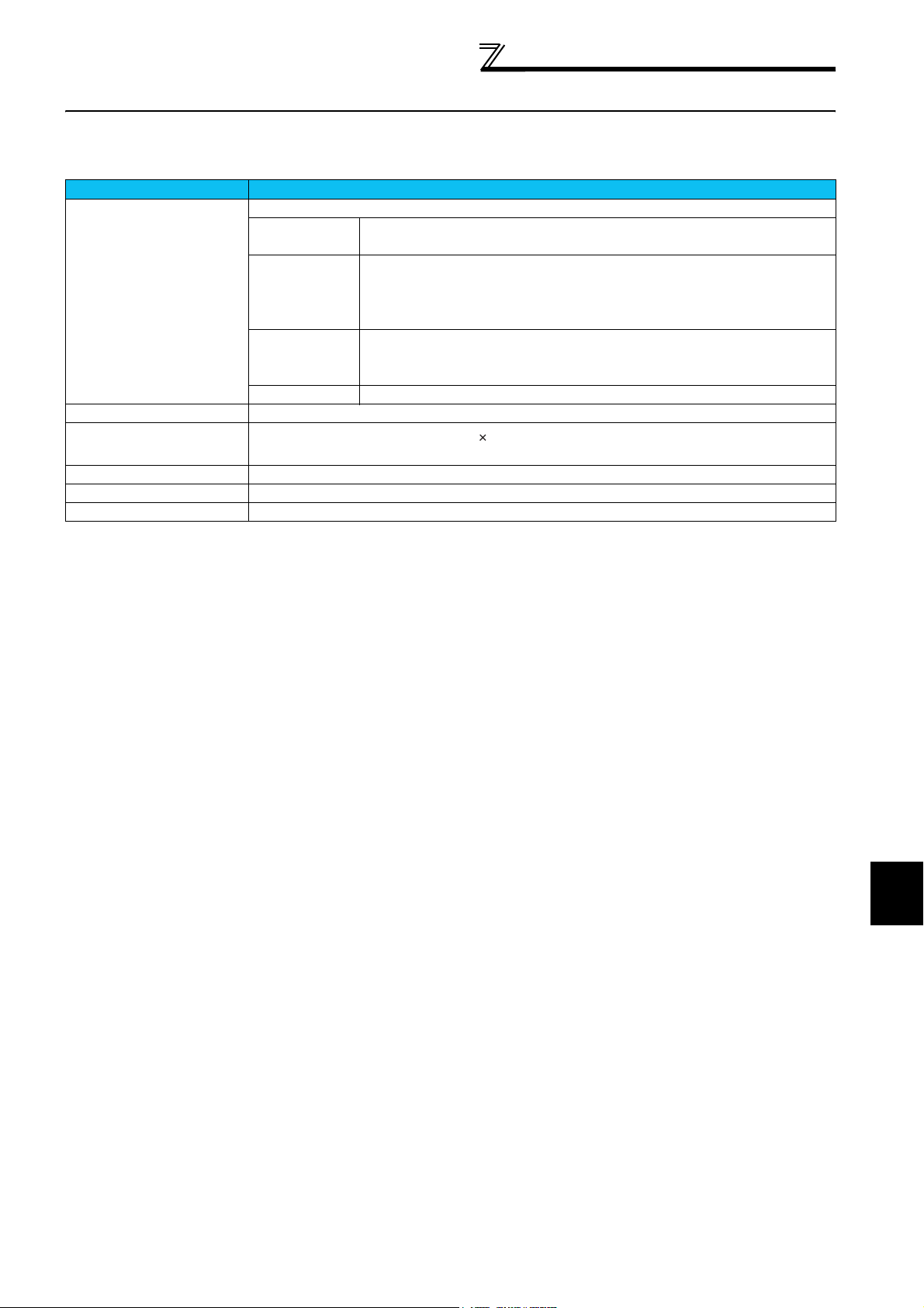
1.2.1 System configuration
Components Description*1
Personal computer*2 IBM PC/AT compatible machine with CD-ROM drive (for installation), USB port *3 or RS-232C port
OS Windows® XP Professional, Windows® XP Home Edition, Windows® 2000
Professional, Windows® Me, Windows® 98 (English)
Pentium® 133MHz or more (Windows® 98‚ Windows® 2000 Professional)
Processor
Memory
Hard disk Free area of 50MB or more
Software Internet Explorer 4.0 or more
Display
Keyboard Connectable to the above PC
Mouse Connectable to the above PC
Printer Connectable to the above PC
Applicable to display at resolution of 800 600 or more, and High Color (16 bits). Connectable to the
above PC.
Pentium® 150MHz or more (Windows® Me)
Pentium® 300MHz or more (Windows® XP Professional‚ Windows® XP Home
Edition)
24MB or more (Windows® 98)
32MB or more (Windows® Me‚ Windows® 2000 Professional)
128MB or more (Windows® XP Professional‚ Windows® XP Home Edition)
*1 Windows is a registered trademark of Microsoft Corporation in the United States and other countries.
Pentium is a registered trademark of Intel Corporation
*2 FR Configurator may not normally operate according to PC used.
*3 The setup using the USB port is available for FR-A700 series only.
1.2.2 Compatible inverters
FR Configurator is compatible with the following inverters.
• FR-A700 series
• FR-F700 series
1
OVERVIEW
3
Page 8
Preparations for Startup
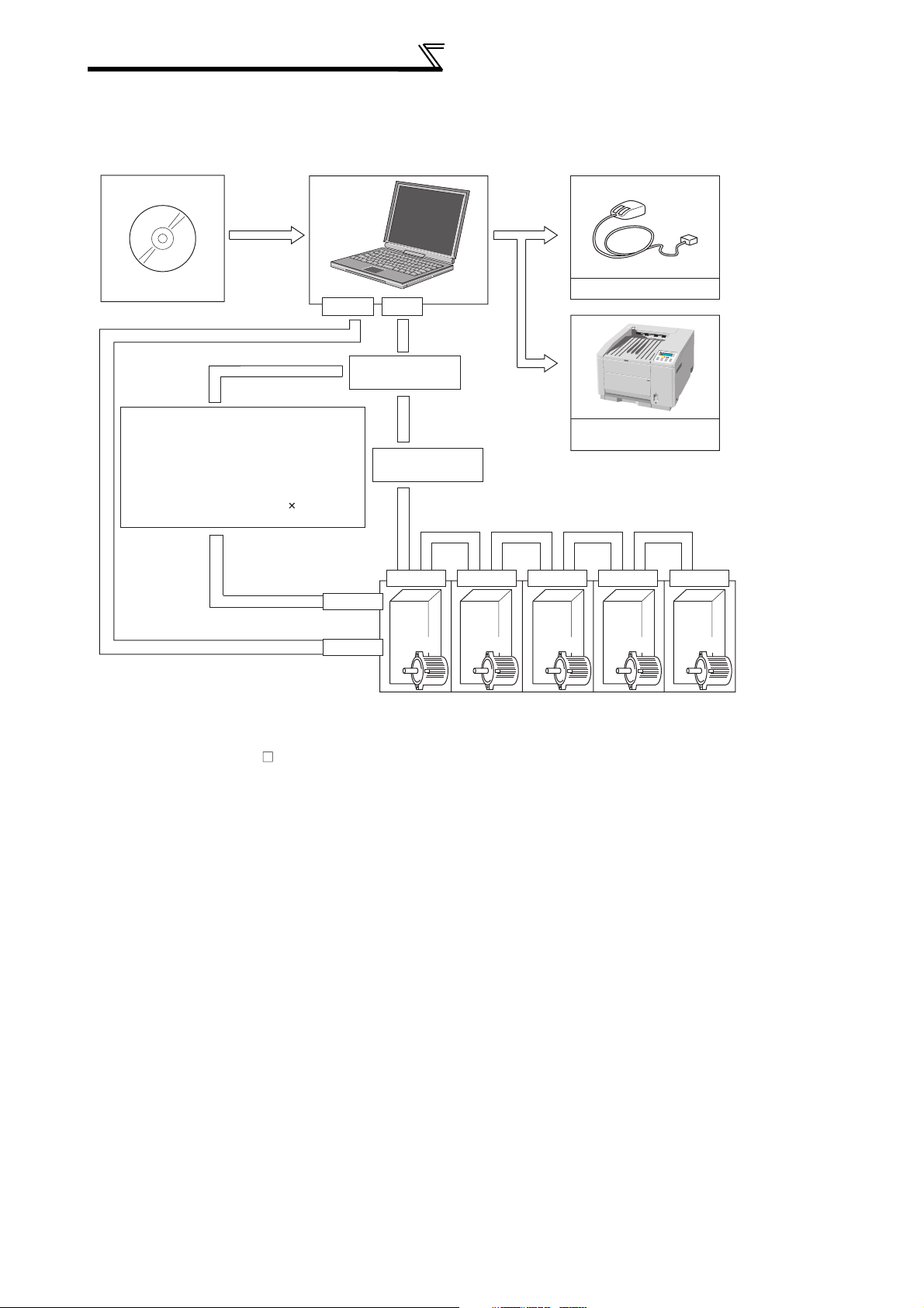
1.2.3 System configuration
The following devices are required to use the FR Configurator. Configure the system in accordance with the instruction
manuals of the corresponding devices.
Mouse
FR Configurator
USB connector used
USB connector
*2*3
RS-232C
PU connector used
*2
Converter
Connection cable
Connector: RJ45 connector
Example: Tyco Electronics Corporation
Cable: Cable in compliance with EIA568
Example: Mitsubishi Cable Industries, Ltd.,
5-554720-3
(such as 10BASE-T cable)
SGLPEV-T 0.5mm 4P
(Twisted pair cable, 4 pairs)
PU connector
USB connector
Connection cable
RS-485/RS-422
RS-485 terminal RS-485 terminal RS-485 terminal RS-485 terminal RS-485 terminal
Inverter Inverter Inverter Inverter Inverter
*1: A converter commercially available is required when the
personal computer uses the RS-232C port.
<Example of a commercially available product>
1) Model: FA-T-RS40 Converter (Model with connectors
and cable is also available)
Mitsubishi Electric Engineering Co., Ltd.
2) Model: DINV-CABV (with connectors and cable)
Diatrend Corp.
The converter cable cannot connect two or more inverters (the
computer and inverter are connected on a 1:1 basis). Since the
product above is packed with the RS-232C cable and RS-485
cable (10BASE-T + RJ-45 connector), the cable and connector
need not be prepared separately. Contact a maker for details of
the product.
*1
RS-485 terminal used
*4
Multidrop link system
*2: The PU connector, RS-485 terminal or USB connector
(FR-A700 series only) can be used to make
communication.
(Refer to the corresponding instruction manual for details.)
*3: The communication using USB connector (available for FR-
A700 series only) cannot connect two or more inverters. (the
personal computer and inverter are connected on a 1:1 basis)
Also, the communication using USB HUB can not be made.
*4: Overall length of connection cable: 500m
*2
Commercially available
printer
Inverter
4
Page 9
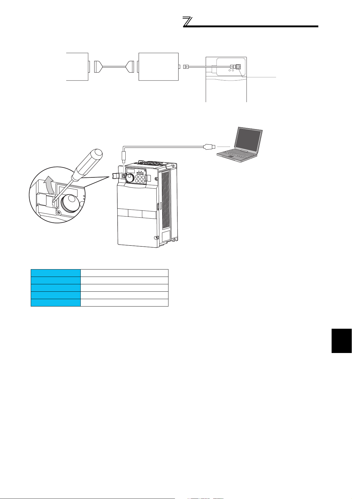
[Connection example between converter and inverter (PU connector)]
Preparations for Startup
Personnel computer
RS-232C
port
RS-232C
cable
[Connection of USB cable and USB connector]
FA-T-RS40
(RS-232CRS-485
converter)
USB cable
RS-485
cable
USB connector
Inverter
PU connector
Removal of cover
Hook the dent with a flat blade screw
driver, etc. and push it up to open the
cover.
Interface
Transfer speed
Wiring length
Connector
Power supply
Conforming to USB 1.1
12Mbps
Maximum 5m
USB connector (B receptacle)
Supplied by self-power
1
OVERVIEW
5
Page 10
Preparations for Startup
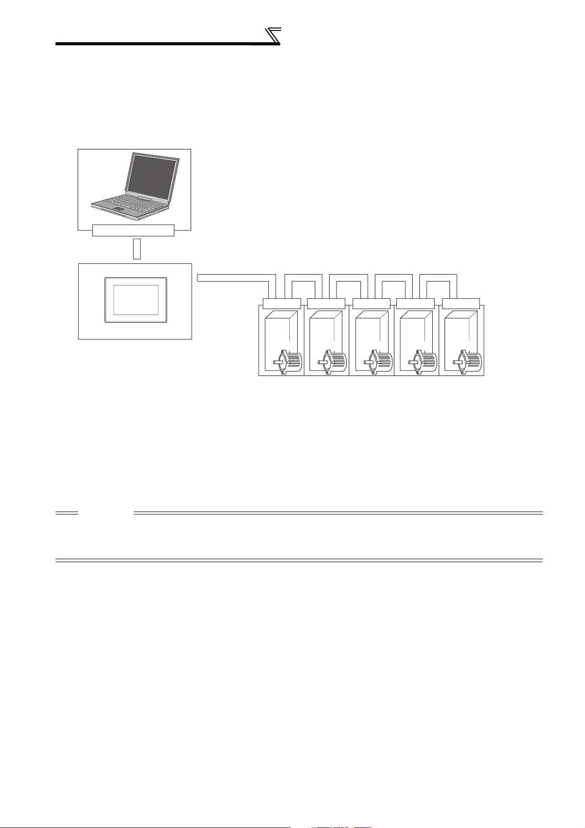
[Connection via GOT (FA transparent function)]
The FA transparent function allows the sequence programs of the Mitsubishi PLC to be read, written and monitored from a PC
connected via a GOT.
Using FA transparent function of GOT1000 series, communication with inverter via GOT is enabled.
• RS-232C or USB connection is used between FR Configurator and GOT
• RS-422 is used between GOT and inverter
USB connector or RS-232C
*1: GOT RS-422 communication unit (GT15-RS4-9S) is
required.
*2: USB or RS-232C(one from Port 1 to Port 9) can be used
for communication port, and setting must be made in
Communication settings screen of the FR Configurator
(Can not use multiple Ports simultaneously).
The personal computer and GOT is connected on a 1:1
basis. Also the communication using USB HUB can not
be made.
*2
RS-422 terminal is used
*1
*4
RS-485 terminal
Inverter Inverter Inverter Inverter Inverter
*3: Up to 10 inverters can be connected with RS-422
*4: Refer to GOT1000 Series Connection Manual for the
Up to 10 inverters
connection. Inverter station number can be set from 0 to
31.
compatible version of the GOT and details of RS-422
connection.
*3
RS-485 terminalRS-485 terminalRS-485 terminalRS-485 terminal
CAUTION
Do not perform the following operation during FA transparent function is valid and FR Configurator is ONLINE.
1. Online operation (project download, etc.) from GT Designer/GT Designer2 to GOT
2. Online operation to the PLC CPU by using FA transparent function of GX Developer
Inverter
6
Page 11
Preparations for Startup
1.2.4 Installation of FR Configurator
To use the FR Configurator (FR-SW2-SETUP-WE), the files included in the setup disks must be installed onto the personal
computer.
REMARKS
FR configurator is installed in a different folder from that of the old version inverter setup software. The old version inverter setup software
can be also used continuously.
However, when installing the old version inverter setup software after the installation of FR Configurator, FR Configurator will not operate.
In this case, uninstall FR Configurator (refer to page 10) and then install it again.
If the older version of the FR Configurator is installed (version information can be checked in "About VFD Setup S/W" screen, refer to page
67), uninstall the older version, and then install the new version of the FR Configurator.
To install the old version of the FR configurator, use the setup program (SETUP.EXE) on the Setup Disk . The setup program
creates a directory on the specified hard disk and copies the required files.
CAUTION
Since the files in the Setup Disk are compressed, the FR-Configurator will not operate by merely copying the files. Always use the setup
•
program to install the software.
• Install the software in accordance with the Windows installation procedure.
• For uninstallation method, refer to page 10.
Installation procedure
The following describes the procedures for installing the FR Configurator to a personal computer.
CAUTION
Close any other applications that have already been started.
•
• When installing to Windows 2000/XP (Professional/Hope Edition) OS, login as a user name with administrator authority (Administrator
authorization) and install it.
• If an inverter is connected by the USB cable, disconnect the USB cable.
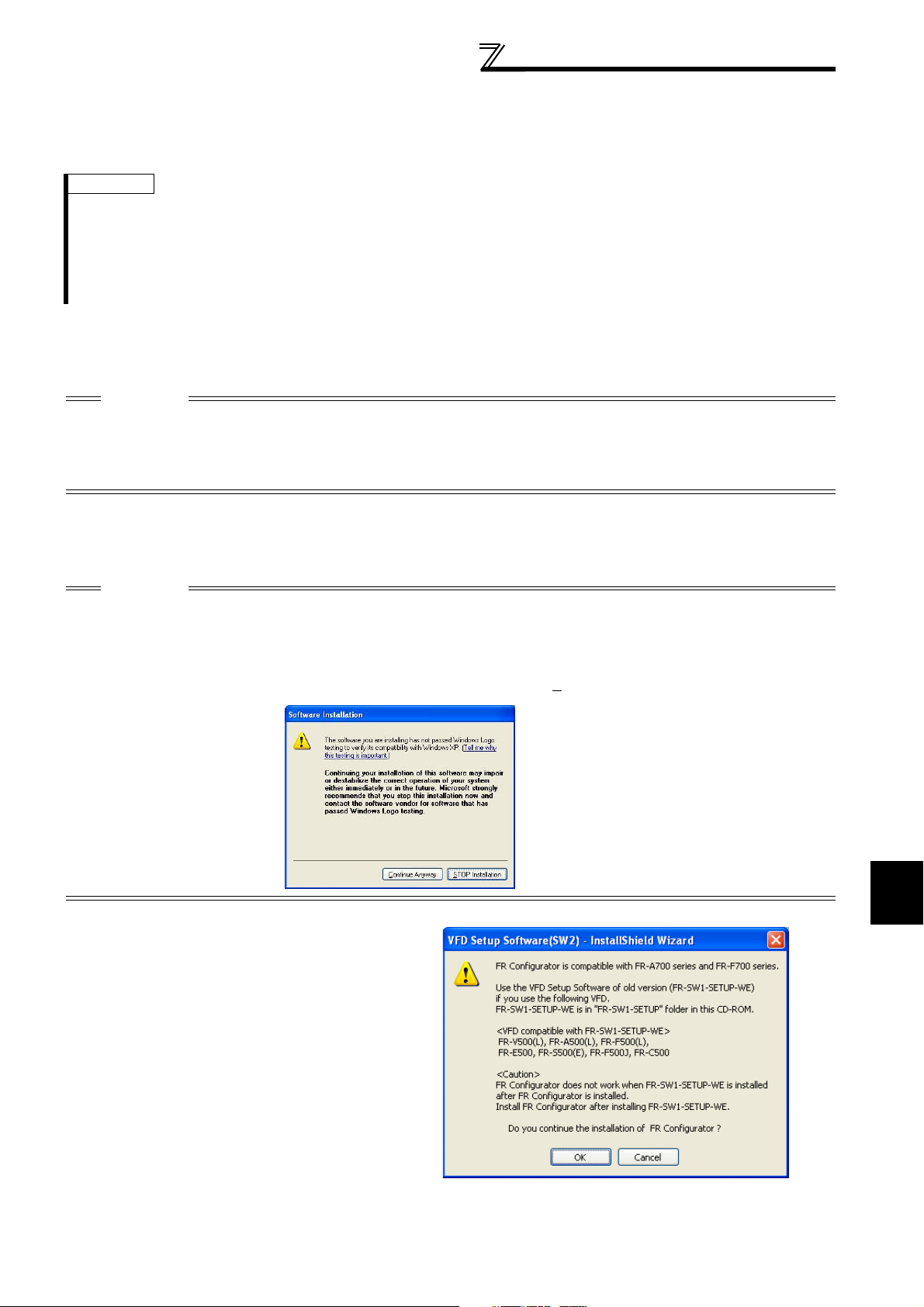
• If the following verification screen is displayed during the installation, click [Continue(C
(1) Insert the CD-ROM to the drive of which CD-ROM
can be read. When the screen shown on the right is
displayed, click [OK] to continue the installation of the
FR Configurator.
)] to continue the installation.
1
OVERVIEW
7
Page 12
Preparations for Startup
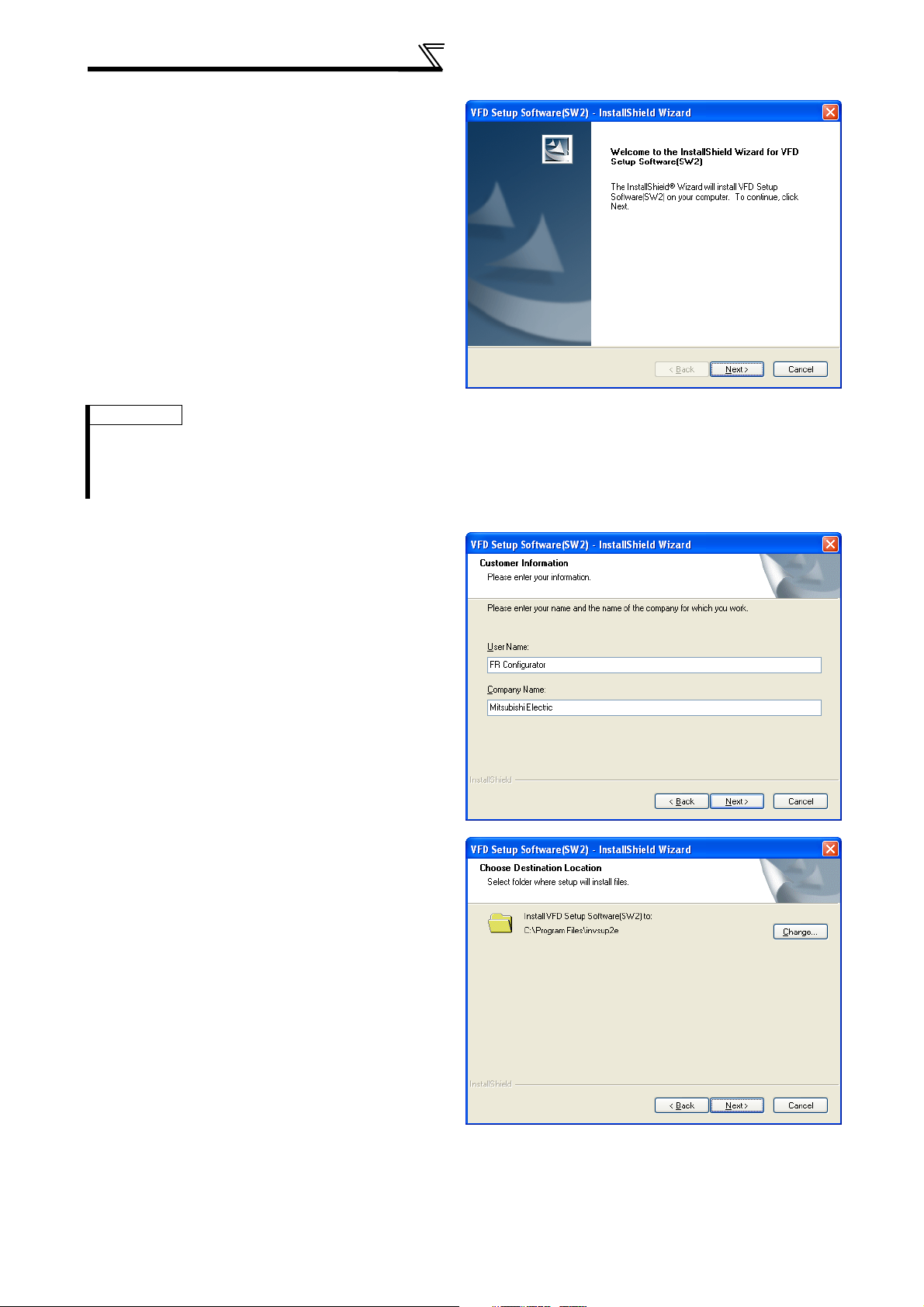
(2) The screen shown right is displayed.
Click the "Next" button.
REMARKS
The above screen can be displayed with double-clicking the icon of CD-ROM drive or the following procedure.
(1) Choose the [Execute it by specifying a file name (R)] command from [Start] menu.
(2) The display of [Execute it by specifying a file name (R)] appears.
(3) Input "D:\SETUP" (with one-byte characters) to "Name (O)" and click the "OK" button. (When CD-ROM drive is D drive)
(3) Enter a user name and company name in one byte
characters.
After entering, click the "Next" button.
(4) Check the installation destination folder and click
"Next" button.
When changing the installation destination, click
"Change..." and change it.
8
Page 13
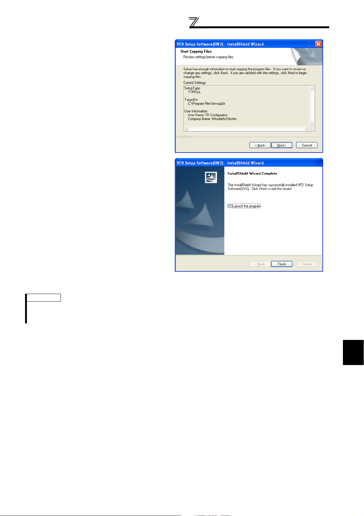
(5) Check the settings, and click "Next" if there is no
problem.
When changing the settings, click "<Back" and
correct them.
(6) The installation is completed.
Click the "Finish" button to finish.
By checking "Launch the program", the program will
start right after the "Install Shield Wizard" is finished.
Preparations for Startup
(7) When the installation is finished, a shortcut is created in the [Start] menu.
REMARKS
If the user does not have the administrator authority (Administrator authorization) with Windows XP/2000 OS, the installation cannot be
made.
Login as a user with administrator authority and start the installation again.
1
OVERVIEW
9
Page 14
Preparations for Startup
1.2.5 Uninstallation of FR Configurator
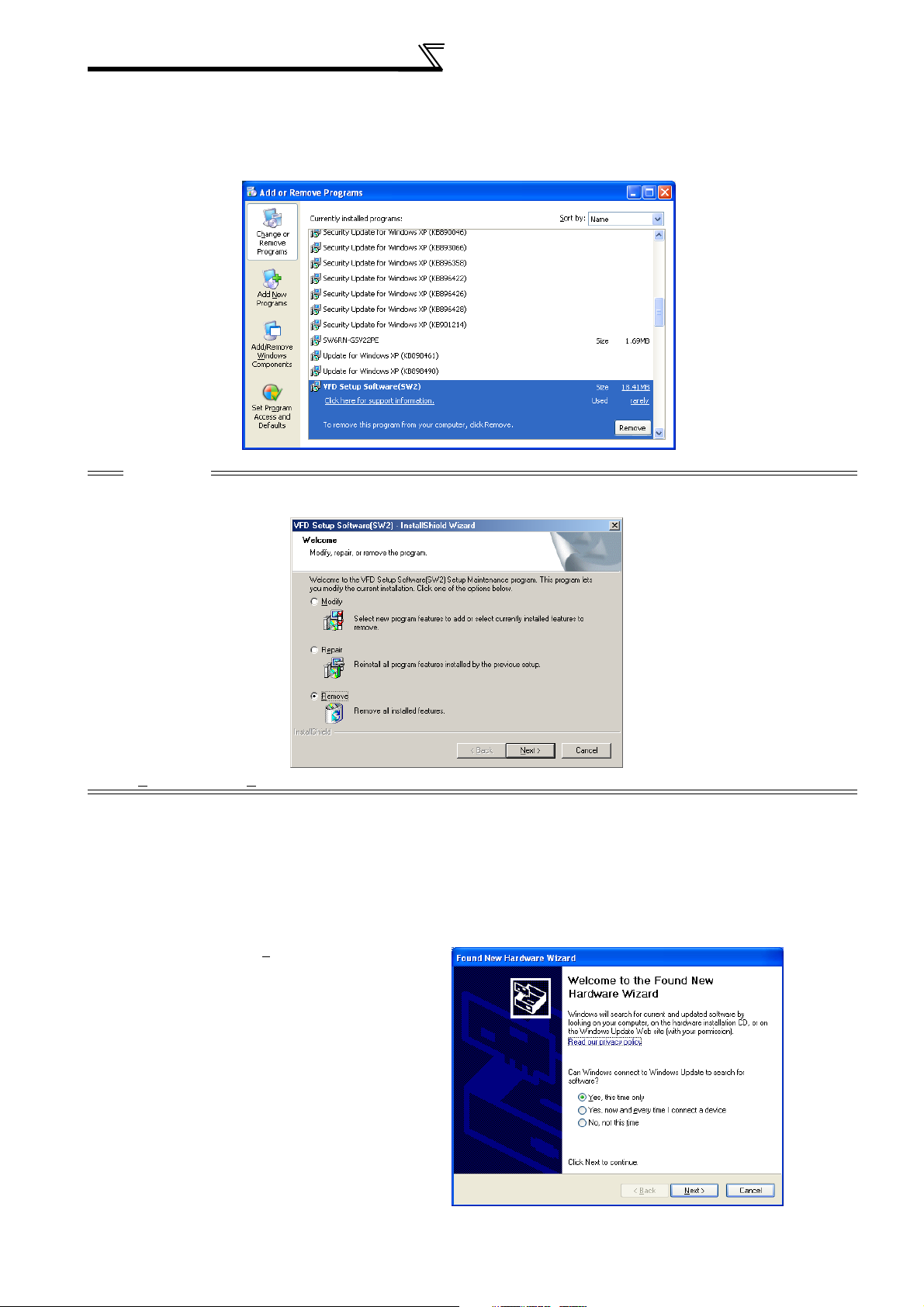
Select "Add or Remove Programs" from [Start] - [Setting] - [Control panel] and display the following screen.
Select "VFD Setup Software(SW2)" and click the "Remove" button to execute the uninstallation.
CAUTION
If the operation system is Windows 98SE or Windows Me, the following screen appears during the uninstallation.
Select [Remove] and click [Next>] to proceed the uninstallation.
1.2.6 When connecting USB for the first time (FR-A700 series)
If a personal computer and inverter are connected via USB for the first time with the inverter power on, Found New Hardware
Wizard is displayed.
The following additional wizard is displayed for Windows 98SE/Me/XP only.
For Windows 2000, it is automatically detected.
(1) Check the radio button "Yes, this time only" and click
the "Next" button.
10
Page 15
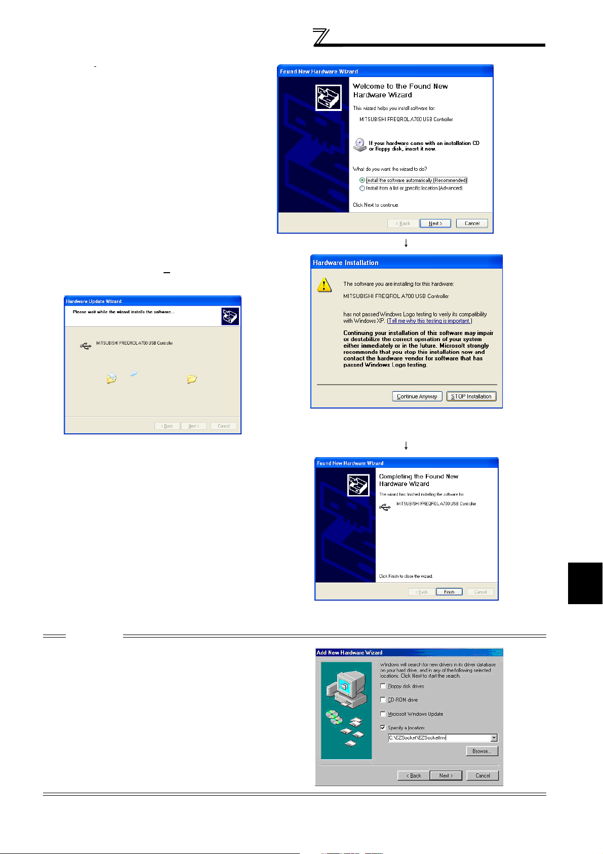
(2) Check "Install the software automatically
(Recommended)" and click the "Next" button.
(3) If the screen shown on the right is displayed when
using Windows XP, click [Continue Anyway] to start
the installation.
Preparations for Startup
(4) The installation of driver is completed.
Click "Finish" to complete.
CAUTION
When the dialogue box shown on right appeared while using
Windows 98SE and Windows Me, check the "Specify a
location" and specify "C:\EZSocket\EZSocketInv", and then
click "Next>" button.
If the FRA700.inf file is not in the folder above, search the
FRA700.inf file and specify that folder.
1
OVERVIEW
11
Page 16

MEMO
12
Page 17

2 FUNCTIONS
This chapter describes the "functions" of this product.
Always read the instructions before using this software.
2.1 Starting FR Configurator..........................................14
2.2 Menu list ..................................................................15
2.3 Saving, Reading and Printing the Files ...................16
2.4 Explanation of Screen .............................................18
2.5 Operation Mode Setting of the Inverter ...................21
2.6 FR Configurator Setting [Setting] ............................23
2.7 Parameter Setting [Parameter]................................ 27
2.8 Monitoring Inverter Status [Monitor] ........................ 43
2.9 Inverter Failure Check [Diagnosis] ..........................54
2.10 Test Running ...........................................................58
2.11 Advanced Function.................................................. 61
2.12 Help ......................................................................... 66
13
1
2
3
4
Page 18

Starting FR Configurator
2.1 Starting FR Configurator
Click [Start] , point to [All Programs] , point to [MELSOFT application] , point to [FR Configurator] and then click [FR
Configurator] to start FR Configurator.
14
Page 19
2.2 Menu list
This software has the following functions:
Menu list
Menu Pull-Down Menu Function/Operation
Open (Ctrl+O) Opens a file.
Close Closes the screen.
File
Save As (Ctrl+A) Saves data.
Print (Ctrl+P) Selects printing.
Exit Exit FR Configurator.
V
iew System list Displays a system list. 19
System Settings Sets the model, capacity and option type. (Stations 00 to 31)
S
ettings
Communication
Settings
Environmental
Settings
Sets communication information.
Set the place for saving data (directory) and the operation at the start-up.
All List Format Shows the parameter list, and parameter setting can be made.
Functional List Format Shows and sets the related parameters function-by-function.
A total of 32 parameters out of all parameters can be registered to two
different user groups to be managed.
The parameters required for starting up the inverter can be set without
being aware of parameter numbers.
Assigns functions to the inverter I/O terminals.
Converts the parameter settings automatically at replacement from the
conventional mode
P
arameter
Individual List Format
Basic Settings
I/O terminals
Allocations
Convert Function
Data Display Shows four pieces of data (up to 4 signals) in terms of meter deflections.
Monitors the status of the inverter I/O terminals. 44
3 analog signals and 4 digital signals (up to 7 signals) can be output in
waveform.
Lists the operation status, operation mode and error existence of all inverter
stations.
Shows various data of all stations connected in real time in terms of
values.
Displays the alarm history of all inverters connected.
Displays inverter part replacement indication.
Estimates the cause of faults from the situation.
Gives the operation command from the personal computer to actually test
run the inverter.
Performs auto tuning.
Measures the response frequency characteristic of speed relative to the
motor torque of the machine.
Overlapping Windows.
Windows are side-by-side.
Explains the use of FR Configurator and the description of parameters,
etc.
Version information (copyright, version information, user and company
names, etc.)
M
onitor
osis
Diagn
T
est Running
Advanced (Z
W
indow
elp
H
I/O terminal monitor
Oscilloscopes
Status Monitor
V
FD Status
larm History
A
Life Check (D
T
rouble Shoot
T
est Running
uto Tuning
A
)Machine Analyzer
C
ascade Display
T
ile Display
H
elp
About VFD Setup S/W
)
Refer to
page
17
-
16
17
-
23
25
26
28
33
34
35
36
38
43
45
53
54
55
56
57
58
59
61
-
-
66
67
2
15
FUNCTIONS
Page 20
Saving, Reading and Printing the Files
2.3 Saving, Reading and Printing the Files
2.3.1 File types
Extensi
on
*.MEL
*.MMT Manages the Data Display in monitoring. (one screen) Data Display 43
*.GPI Manages the oscilloscope data in monitoring. (one screen) Oscilloscopes 45
*.JPEG Saves the oscilloscope data as images. Oscilloscopes 45
*.TXT Saves the parameter list (one station) in a text file format.
*.CSV
*.PRM
*.XLS
*.HDT
Manages the system setting and parameter lists of all stations as a
single file.
Saves the parameter list (one station) in a text file format.
Saves the oscilloscope data in a text file format.
Saves the parameter list (one station) in a text format.
Used to copy the parameter settings to other inverters (other stations).
Saves the parameter list (one station) in a Microsoft Excel file format.
(Editable with Microsoft Excel 97 or later)
Saves the frequency characteristic measurement data of Machine
Analyzer
Description Target screen
System Setting, All List Format 23, 28
All list Format, Functional List
Format, Individual List Format, Basic
Setting Format 2
All List Format, Functional List
Format, Individual List Format, Basic
Setting Format 2, Oscilloscopes
All List Format, Functional List
Format, Individual List Format, Basic
Setting Format 2
All List Format, Functional List
Format, Individual List Format, Basic
Setting Format 2
Machine Analyzer 61
Refer to
2.3.2 Saving method
page
27
27, 45
27
27
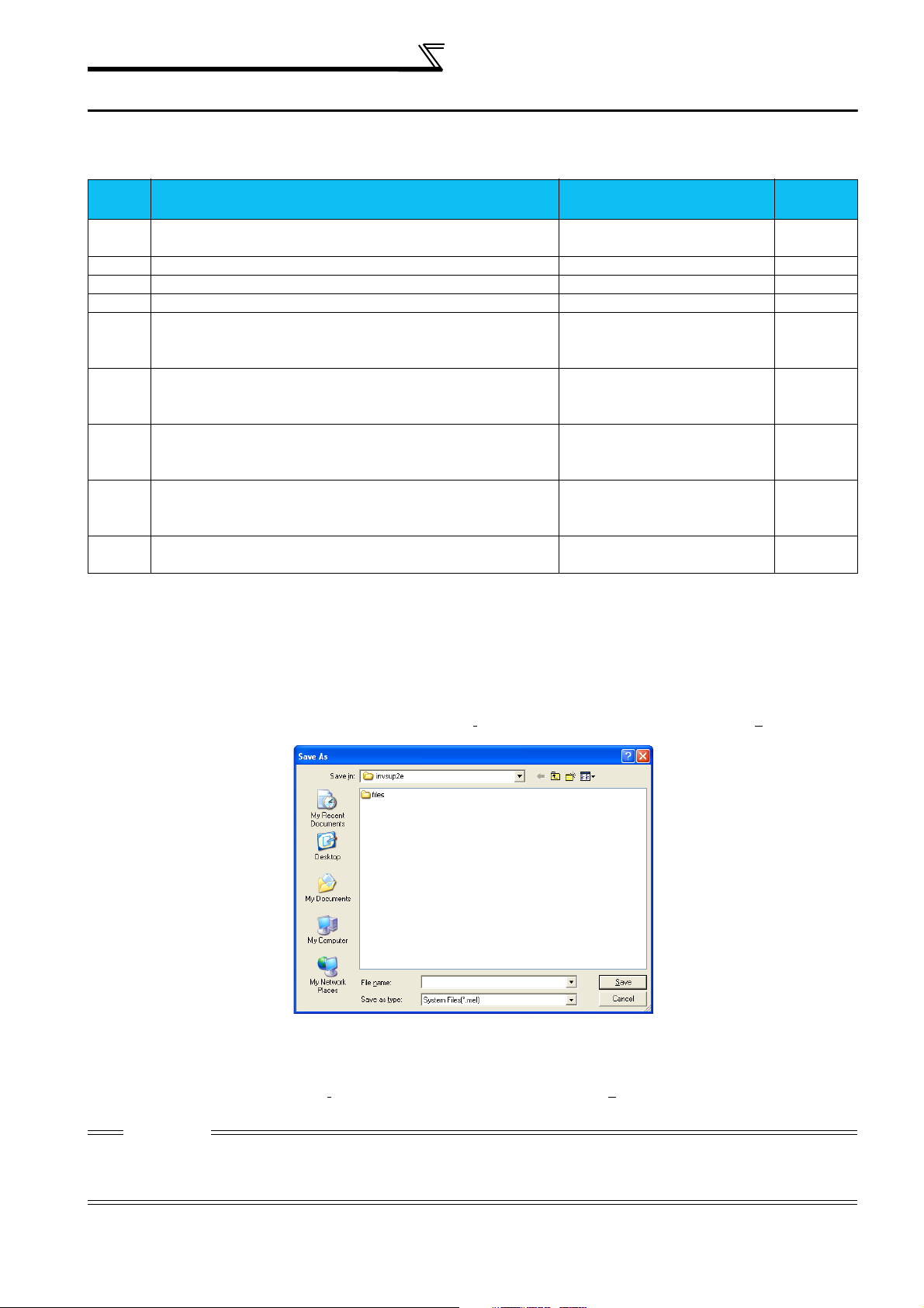
(1) *.MEL file
When the system settings or parameter lists to be saved are open, choose the [Save] command from the [File] menu. The
"Save As" panel appears. Select the file type from "Save as type", and save the file with the name in "File name" field.
(2) *.MMT, *.GPI, *.JPEG,*.HDT, *.TXT, *.CSV, *.PRM, *.XLS files
Choose the [Save] command from the [File] menu on the corresponding display screen. The "Save As" panel appears.
Select the file type from "Save as t
ype", and save the file with the name in "File name" field.
CAUTION
When saving *.TXT, *.CSV, *.PRM and *.XLS files from the Functional List Format, Individual List Format or Basic Settings format 2, only
the parameters displayed are saved.
When saving all the parameter setting values, save in all list format.
16
Page 21
Saving, Reading and Printing the Files
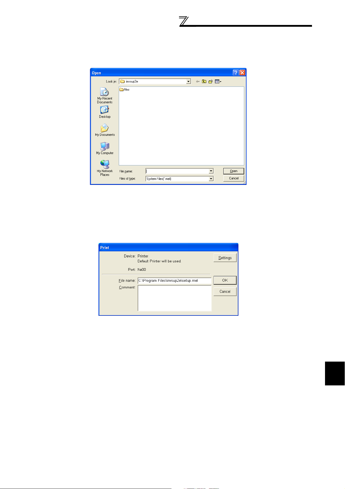
2.3.3 Reading the file
To read the saved file, choose the [Open] command from the [File] menu. The "Open" panel appears. Choose the file to
be read and click the [OK] button to read the saved data.
2.3.4 Printing
Display the screen to be printed and choosing the [Print] command in the [File] menu displays the "Print" panel. Make printer
and other settings and click the [OK] button to start printing.
When entering a comment in the comment area, the comment can be printed with it.
17
2
FUNCTIONS
Page 22
Explanation of Screen
2.4 Explanation of Screen
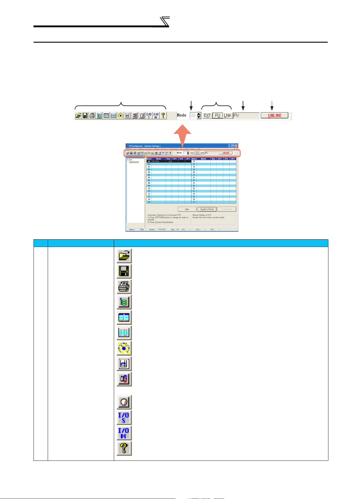
2.4.1 Tool bar
Tool bar is comprised of tool buttons which have functions commonly used in the menu, and the menu can be executed
quickly by clicking the icons.
In addition, selection of station number and operation mode, online/offline settings are also available.
A
No. Name Function and description
Function tool button
A
.........Opens a file.
(Refer to page 17)
.........Saves the data.
(Refer to page 16)
.........Prints.
(Refer to page 17)
.........Displays a system list.
(Refer to page 19)
.........Makes settings of model, capacity and plug-in option.
(Refer to page 23)
.........Displays a parameter list and makes a parameter setting.
(Refer to page 28)
.........Displays four data with analog meter and numerical value.
(Refer to page 43)
.........Displays data of three analog signals and four digital signals as waveform.
(Refer to page 45)
.........Gives an operation command from a personal computer and executes a test operation
on the inverter.
(Refer to page 58)
.........Executes an auto tuning.
(Refer to page 59)
.........Assigns functions to the inverter I/O terminals.
(Refer to page 36)
.........Monitors the status of the inverter I/O terminals.
(Refer to page 44)
.........Explains the use of FR Configurator and the description of parameters, etc.
(Refer to page 66)
B
C
D
E
18
Page 23
Explanation of Screen
No. Name Function and description
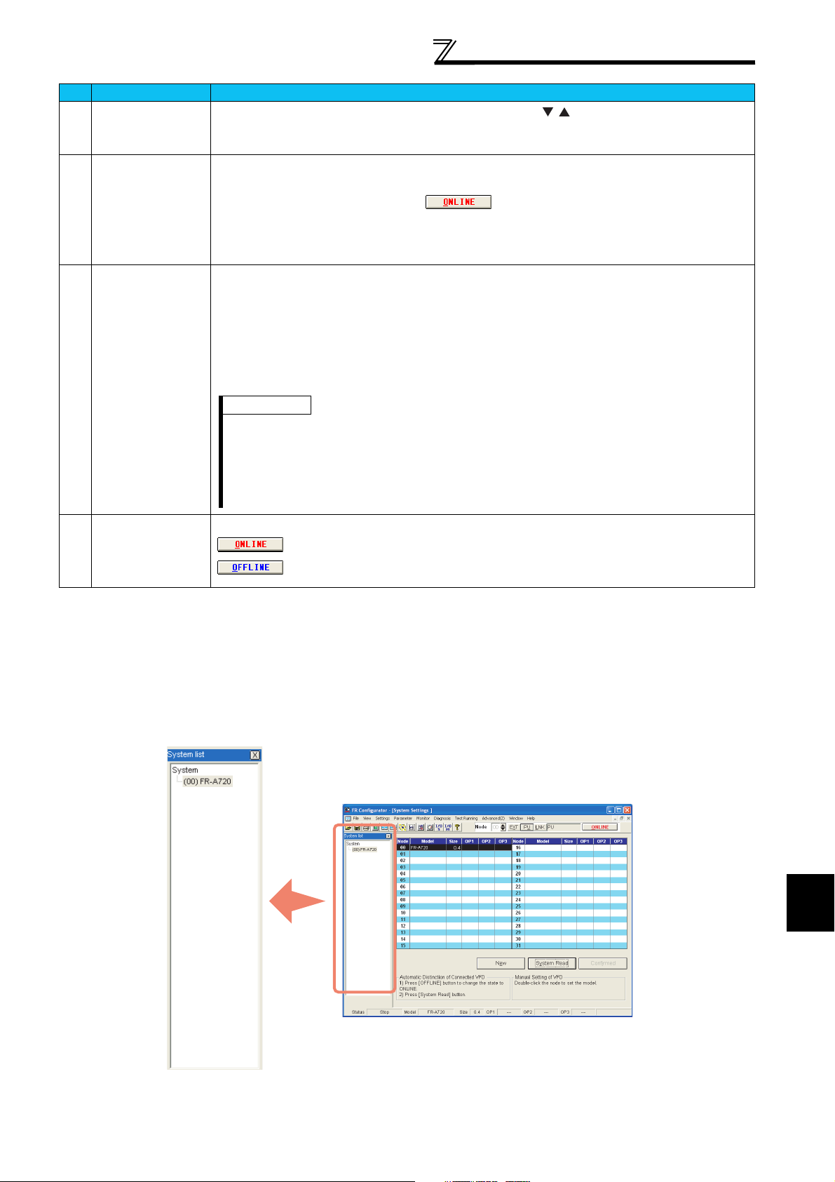
Station number
B
selection
Operation mode
C
button
Operation mode
D
indication
Online button Switches Offline and Online by clicking. Pressing [Alt] key and [o] key can also switch Offline and Online.
E
Selects a station number to be displayed on the screen using the / button. (Only station number set
with the system setting is displayed in the displaying column.
Direct enter of displaying column is also available.
Sets the operation mode by clicking each button.
The set operation mode is displayed in the displaying column of operation mode.
Valid only when the online button is in the status.
• [EXT] (Alt+X): External operation mode
• [PU] (Alt+U): PU operation mode
• [LNK] (Alt+L): Network operation mode
• EXT: External operation mode
• PU: PU operation mode
• LNK: Network operation mode
• EXT JOG: External JOG operation mode
• PU JOG: PU JOG operation mode
• PU+EXT: External/PU combined operation mode
• No Node: when the time-out occurs in the ONLINE mode
REMARKS
• The operation mode + alarm (warning) descriptions are displayed at the alarm occurrence or during the
warning indication. Displayed in red letters at the alarm occurrence.
Example: When the overcurrent shut-off during acceleration occurs during PU operation ... PU (OC1)
When PU stop occurs during EXT operation ... EXT (PS)
At the occurrence of communication error such as NAK or the occurrence of inverter error such as out of
•
parameter range, error codes are displayed.
...Online
...Offline
(page 70)
2.4.2 System list
The system list is displayed with the system setting screen when starting FR Configurator.
The model name and station number set with the system setting are displayed on the list.
The inverter (station number) selected on the system list becomes active on thez parameter setting screen or alarm display
screen.
When the system list window is closed, select [System list] of the [Display] menu to display again.
2
19
FUNCTIONS
Page 24
Explanation of Screen
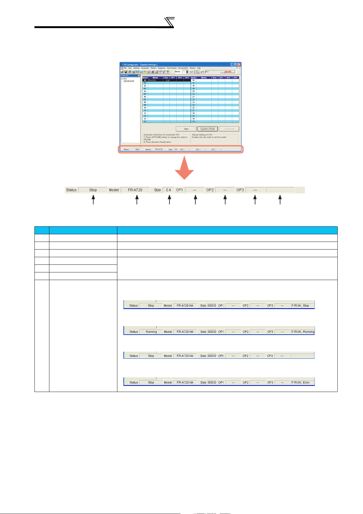
2.4.3 Status bar
AB DEC
No. Name Function and description
Status Displays the inverter operation status (Running/Stop/Off Line/Error) of selected station.
A
Model Displays the inverter model name of selected station.
B
Size Displays the inverter size of selected station.
C
OP1 Displays the name of plug-in option mounted on the inverter of selected station.
D
OP2
E
OP3
F
PLC Function status
G
(FR-A700-NA/EC series only)
(The number of plug-in options which can be mounted on an inverter differs according to the
inverter.)
Displays the state of PLC Function.
PLC Function: Stop
PLC Function: Running
PLC Function: Disabled
PLC Function: Error
F
G
20
Page 25
Operation Mode Setting of the Inverter
2.5 Operation Mode Setting of the Inverter
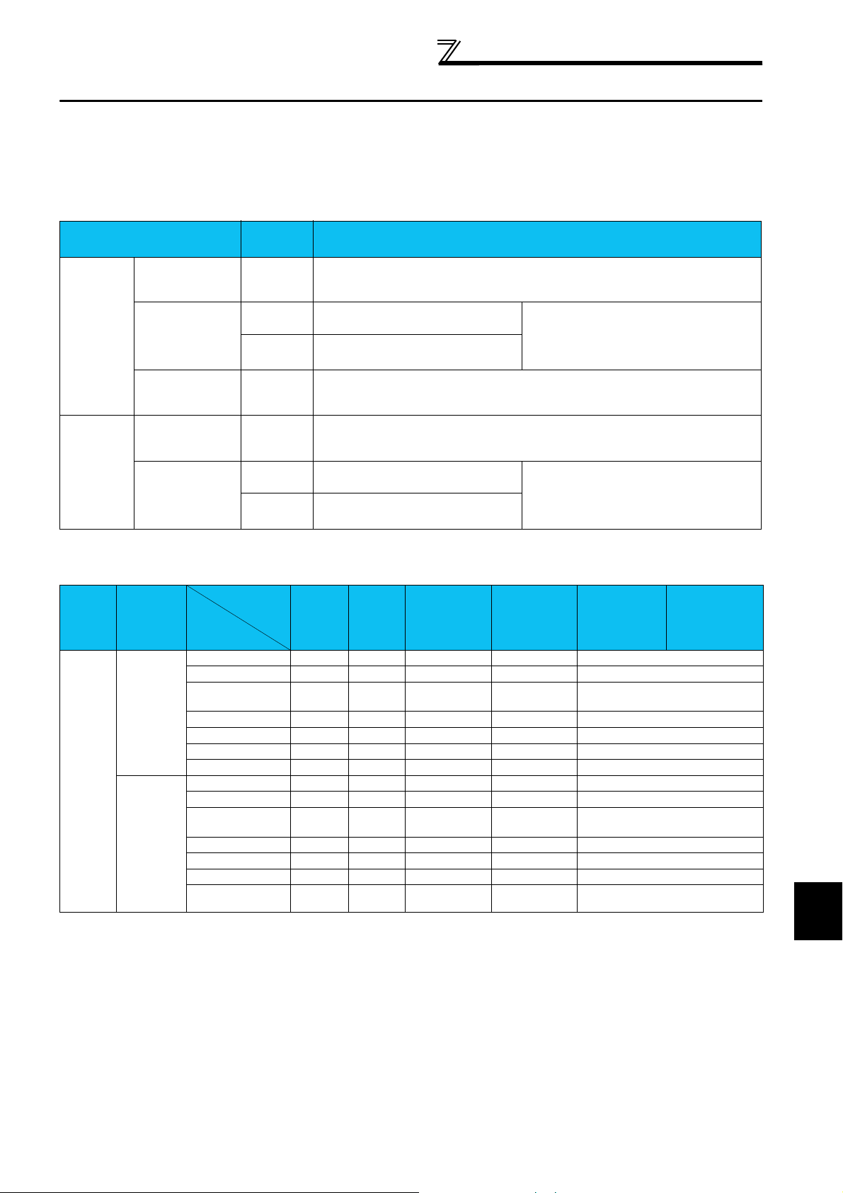
2.5.1 Operation mode setting
For operating the inverter using FR Configurator (parameter change, auto tuning and test operation, etc.), the operation mode
of inverter must be set. Refer to the table, and select an operation mode, which matches to each connecting method. The
selection of operation mode can be made using the tool bar. (Refer to page 18)
Connecting method
PU connector
Direct
connection
with FR
Configurator
and the
Inverter
Connection
via GOT
* When connecting a USB connector, set "3" in Pr.551 PU mode control source selection. The change for the setting value of Pr.551 becomes valid when turning on
the power next time or resetting the inverter.
(RS-485
connector)
RS-485 terminal
USB connector
(FR-A700
series only)
PU connector
(RS-485
connector)
RS-485 terminal
Operation
mode*
PU
PU
LINK Pr. 551 PU mode control source selection
PU
PU
PU
LINK Pr. 551 PU mode control source selection
Pr. 122 PU communication check time interval
Pr. 123 PU communication waiting time setting
Pr. 551 PU mode control source selection
(Factory setting)
Pr. 548 USB communication check time interval
Pr. 551 PU mode control source selection
Pr. 123 PU communication waiting time setting
Pr. 551 PU mode control source selection
Pr. 551 PU mode control source selection
(Factory setting)
Parameter setting
≠ 0 (Factory setting = 9999)
= 9999 (Factory setting)
= 2
= 1
= 3
= 2 (Factory setting)
= 2
= 1
Pr. 336 RS-485 communication check time
≠ 0
interval
Pr. 337 RS-485 communication waiting time
= 9999 (Factory setting)
setting
≠ 0 (Factory setting = 9999)
= 0
Pr. 336 RS-485 communication check time
≠ 0
interval
Pr. 337 RS-485 communication waiting time
= 0
setting
Controllability through communcation
Operation
Location
Control by RS-485 communication from PU connector
Condition
(Pr. 551
Setting)
2
(PU
connector)
Except for 2
Operation
Mode
Item
Run command (start)
Run command (stop)
Running frequency
setting
Monitor {{ { { {
Parameter write { *4 × *5 { *4 { *4 × *5
Parameter read {{ { { {
Inverter reset {{ { { {
Run command (start)
Run command (stop)
Running frequency
setting
Monitor {{ { { {
Parameter write ×
Parameter read {{ { { {
Inverter reset {{ { { {
PU
Operation
{ ×× { ×
{ *3 *3 { *3
{ × { ××
*3 *3 *3 *3 *3
External
Operation
×× × × ×
×× × × ×
*5 × *5 × *5 × *5 × *5
External/PU
Combined
Operation Mode
1
Pr. 79
= 3)
(
External/PU
Combined
Operation
Mode 2
(Pr. 79 = 4)
NET Operation
(when RS-485
terminals are
used)
*6
NET Operation
(when
communication
option is used)
*7
2
21
FUNCTIONS
Page 26

Operation Mode Setting of the Inverter
Operation
Location
RS-485 terminals
Control by communication from
Operation from the USB connector*8
Condition
(Pr. 551
Setting)
1
(RS-485
terminals)
Except for 1
3 (USB
connector)
Except for 3
Operation
Mode
PU
Operation
External
Operation
Item
Run command(start,
stop)
Running frequency
setting
Monitor {{ { { {
Parameter write { *4 × *5 { *4 { *4 × *5
Parameter read {{ { { {
Inverter reset {{ { { {
Run command
(start, stop)
Running frequency
setting
Monitor {{ { { { {
Parameter write × *5 × *5 × *5 × *5 { *4 × *5
Parameter read {{ { { { {
Inverter reset ×× × × {
Run command
(start, stop)
Running frequency
setting
Monitor {{ { { {
Parameter write { *4 × *5 × *5 × *5 × *5
Parameter read {{ { { {
Inverter reset {{ { { {
Run command
(start, stop)
Running frequency
setting
Monitor {{ { { {
Parameter write × *5 × *5 × *5 × *5 × *5
Parameter read {{ { { {
Inverter reset {{ { { {
{ ×× { ×
{ × { ××
×× × × { *1 ×
×× × × { *1 ×
{ ×× { ×
{ × { ××
×× × × ×
×× × × ×
External/PU
Combined
Operation Mode
1
Pr. 79
= 3)
(
External/PU
Combined
Operation
Mode 2
(Pr. 79 = 4)
NET Operation
(when RS-485
terminals are
used)
*6
*2 ×
NET Operation
(when
communication
option is used)
*7
{: Enabled, ×: Disabled, : Some are enabled
*1 As set in Pr. 338 Communication operation command source and Pr. 339 Communication speed command source. (Refer to the inverter Instruction Manual
(applied)
*2 At occurrence of RS-485 communication error, the inverter cannot be reset from the computer.
*3 Enabled only when stopped by the PU. At a PU stop, PS is displayed on the operation panel. As set in Pr. 75 Reset selection/disconnected PU
detection/PU stop selection. (Refer to the inverter
*4 Some parameters may be write-disabled according to the Pr. 77 Parameter write selection setting and operating status. (Refer to the inverter
)
Instruction Manual (applied))
Instruction Manual (applied))
*5 Some parameters are write-enabled independently of the operation mode and command source presence/absence. When Pr. 77 = 2, write is
enabled. (Refer to the inverter
*6 When Pr. 550 NET mode operation command source selection = 1 (RS-485 terminals valid) or Pr. 550 NET mode operation command source selection =
9999 and the communication option is not fitted.
*7 When Pr. 550 NET mode operation command source selection = 0 (communication option valid) or Pr. 550 NET mode operation command source selection
= 9999 and the communication option is fitted.
*8 FR-A700 series only.
Instruction Manual (applied)) Parameter clear is disabled.
2.5.2 Communication device setting of personal computer
Make a setting for the communicating method of personal computer and inverter. Select [Communication setting] in the
[Setting] menu of the FR Configurator menu bar, and then select either "RS-232C" or "USB" from the connecting methods on
the communication setting screen.
For details, refer to page 25.
22
Page 27

FR Configurator Setting [Setting]
2.6 FR Configurator Setting [Setting]
2.6.1 System setting
The system setting is displayed when starting FR Configurator.
This section describes the setting for the station number, model, capacity and plug-in option of inverter to be connected. The
inverter can be set from 0 to 31 stations.
The connected inverter system can be also read all at once.
POINT
After adding or changing the inverter model or capacity, make sure to press the button.
A
B
C
D
23
2
FUNCTIONS
Page 28

FR Configurator Setting [Setting]
No. Name
System setting Sets the environment of inverter from 00 to 31 stations.
A
Select a model and capacity of inverter. Set a type of plug-in option when using a plug-in option.
By double-clicking on the line of station number to be set, the "VFD Structure" panel is displayed.
Set model, capacity and option, and press the [OK] button to complete the setting. With the same
procedures, set all the inverter stations to be connected.
[New] button By clicking the [New] button, the edited system setting and communication setting are initialized
B
(cleared), and a new system is set.
[System Read] button Before pressing the [System Read] button, change the system to the [online] mode by pressing the
C
[ONLINE] button. In the online mode, the system is in the status communicating with the inverter. By
clicking the [System Read] button, the models, capacities and options of all stations (0 to 31 stations)
are read, and connected (communicable) stations are displayed.
Automatically confirmed after the read.
When the system setting has been already registered, the verification is performed. When the
verification result is different from the read data, displays the result of checking, and select to change
the settings or not.
[Confirmed] button The data set the system setting can be confirmed. When the setting of the system configuration is
D
changed manually, make sure to confirm using the [Confirmed] button.
Function and description
CAUTION
• When clicking the [Cancel] button during [System Read], the verification is performed with the system setting up to the point.
• 75K or more of FR-F740-CH is displayed as "FR-F740-CHT" in the [Model] field.
REMARKS
Shortcut key on the [System setting] screen
Menu name Shortcut key*
Open Ctrl + O
Save As Ctrl + A
Print Ctrl + P
* "+" indicates that keys should be pressed at the same time.
Button name Shortcut key*
EXT Alt + X
PU Alt + U
LINK Alt + L
ONLINE/OFFLINE Alt + O
24
Page 29

FR Configurator Setting [Setting]
2.6.2 Communication settings
FR Configurator can control the inverter by communication using RS-232C port or USB port of personal computer.
Communication setting must be set same as the inverter.
When you start this software first, the initial screen appears, then displays the system setting screen. Choose the
[Communication settings] command on the [Settings] menu. The screen then shows the following dialog box, where various
communication settings can be made.
Communication settings will be described below.
POINT
The communication setting is set to the initial value of inverter.
Confirm the communication ports (1 to 9) and communication device (RS-232C/USB) of personal computer.
A
B
C
D
E
No. Name
Communication
A
port type
Communication
B
port number
Baud Rate 19200 Set the communication speed.
C
Data Length 8 Set the data bit length.
D
Parity Check Even Specify the parity bit.
E
Stop Bit 2 Set the stop bit length.
F
Delimiter CR Specify the delimiter at the data trailer.
G
Initial
value
RS-232C
Selects a communication device from either RS-232C or USB. (USB communication is available
for FR-A700 series only.)
1 Selects a communication port of personal computer.
The communication port can be checked by the following procedure.
(1) Click [Start], point to [All Programs]*, point to
[Accessories], point to [System Tools], and
then click [System Information].
* [Programs] for other than Windows XP
(2) Select [Serial]* in [Port] folder of
[Component] in the left pane.
* [Serial] is not displayed for other than Windows
2000 and XP.
(3) Check the [COM] number of "Communication
port" displayed in the right pane.
Example: "1" for "Communication port (COM1)"
(4) Set the confirmed value to the communication port of B.
F
H
I
Function and description
G
O
J
K
L
M
N
2
FUNCTIONS
25
Page 30

FR Configurator Setting [Setting]
No. Name
Initial
Function and description
value
Interrogate Time 1 Sets an interval for sending data (display and error check of the operation mode) to the inverter.
H
The value must be set 2s shorter than the communication check time interval (Pr.122, Pr.336 or
Pr.548). If it is set longer than the setting value of communication check time interval (Pr.122, Pr.
366 or Pr. 548), the inverter will come to an alarm stop.
CAUTION
If the value of Interrogate Time is set shorter, the menu or buttons of each window may
be slow to respond depending on operating model and communication speed.
Time Out* 1000 Sets the time for a personal computer to receive a response from an inverter after sending a data
I
to the inverter from the personal computer. If there is no response after the set time is passed,
"Time out" error will be displayed.
[OK] button Recognizes the setting value on the communication screen and returns to the system setting
J
screen.
[Cancel] button Cancels the communication settings and returns to the system setting screen.
K
[Reflect Default] button Used to omit the setting of the values specified in communication settings from the next time
L
onward.
[Default Read] button
M
[Initial Value] button Used to return the communication setting to the initial value.
N
GOT Transparent
O
communication
Used to read the default values. The value is as set with the [Reflect Default] button.
Check when using FA transparent function.
* When connecting with FA transparent function, set the time-out value in 500ms increments (Example: 500 / 1000 / 1500 /... / 30000).
CAUTION
When using FA transparent communication, communication error (Time Out) may occur when FR Configurator starts communication during Time
Out occurrence in GOT (when GOT is monitoring the inverter which is not connected).
In that case, set the Time Out value more than the following.
Time Out value of GOT[s] x (Retry count of GOT + 1) x 3 x1000[ms] (500ms increments)
If the value above is more than 30[s], make adjustment to "Time Out value" and "Retry count" of GOT so that the value above is less than 30[s].
2.6.3 Environmental Setting
You can specify the place for saving data (directory) and default system.
A
B
C
D
No. Name
Default Data Directory
A
System block read is done at start-up
B
When the parameter is read it is
C
distinguished automatically
Default Sys File
D
Set the folder (directory) displayed first in a data saving screen, "Save with file name", or a
opening file screen,"Open file".
Once the data is saved in a different folder, the same folder where the data is saved and opened
will be displayed when saving the data again.
Turn on the check box to execute automatically [System Read] when starting of FR Configurator. If
the default system file is registered, system block read is not performed automatically at the
startup.
Turn on the check box to hide the parameters read-disabled for parameter batch-read or batchverify from the error panel. (Refer to page 29)
Registers the system file (*.MEL) which is automatically opened when starting FR Configurator. If
the default system file is registered, system block read is not performed automatically at the
startup.
There is no default system file registered at the installation.
Function and description
26
Page 31

Parameter Setting [Parameter]
2.7 Parameter Setting [Parameter]
When system settings are completed, parameter menu can be selected.
Select the [All List Format], [Functional List Format], [Individual List Format], or [Basic Settings] command in the [Parameter]
menu to select the corresponding format, and set parameters. Any parameter setting is changed by first entering new data in
the Updated Val column and then pressing the [Write] or [Blk Write] button. The new data is then displayed in the Present
Setting column. The Present setting column shows the current setting value of the inverter.
Using [I/O terminals Allocation] allows to change or assign the functions of the inverter I/O terminals by selecting from the list.
Using [Convert Function], the parameters of the conventional model inverter can be automatically converted to those of FR-
A700/F700 series.
The communication settings of the inverter must be set before setting parameters. (Refer to page 21)
Saving a file
By selecting [Save] in the [File] menu, a list can be saved.
• MEL file (.mel) ................................... A file saved in MEL format can be opened with FR Configurator afterward.
• PRM file (.prm)..................................A file saved in PRM format can be opened with FR Configurator afterward.
• TXT/CSV file (.txt/.csv)...................... When saved in TXT/CSV format, the file is saved in a text format.
• XLS file (.xls).....................................When saved in XLS format, the file is saved in Microsoft Excel format.
The file can be opened with Microsoft Excel.
27
2
FUNCTIONS
Page 32

Parameter Setting [Parameter]
2.7.1 Displaying all parameters [All List Format]
By selecting the [All List Format] command in the [Parameter] menu or clicking of the tool button, all parameters of the
inverter are displayed as a list. When changing any parameter setting, enter a new value in the parameter column to be
changed, and press the key to set it.
A
B
C
D
EF GH IJ K
REMARKS
By pressing the [F1] key (function key), the explanation (HELP) of selected parameter can be displayed.
No. Name Function and description
Pr Jmp Displays a selected parameter number.
A
Input the parameter number and press key to jump to the designated parameter column.
Setting Range Displays the setting range for a selected parameter.
B
Parameter display area Displays a parameter list.
C
After entering data in the Updated Val Column, the parameter setting value can be changed by
pressing the [Write] or [Blk Write] button. After the parameter writing, the new data is displayed in
the Present Setting column.
If the parameter setting value has been changed from the initial value, the NO. column is displayed
in green.
Word Search Letters inputted in Word Search field is searched among the parameter name. (The sensitivity of
D
one byte character set or 2 byte character set is ignored.)
28
Page 33

Parameter Setting [Parameter]
No. Name Function and description
Change List Displays parameters of which Present Setting value has changed from the Factory Setting as a list.
E
Pr Init Clears (initializes) the parameters of the inverter. (The communication parameters are not
F
initialized.)
Choose the clearing method from "Parameter Clear" or "All Clear" on the following panel and click
the [OK] button to execute clear.
Blk Read Reads all parameters of the selected inverter station number.
G
Read Reads the data of the parameter numbers selected on the screen.
H
Blk Check Batch-checks the parameters of the inverter against those of the personal computer.
I
Blk Write Writes new parameter values to the inverter.
J
(When there are no values in the Updated Val field, the screen for selecting whether the present
settings will be written or not appears. Perform operation following the screen.)
Write Writes the data of the parameter numbers selected on the screen.
K
CAUTION
• If an error occurred during "block read", "block check" or "block write", the parameter list appears on the panel. Double-clicking the error
number in the displayed list shows the details of the error definition on the panel.
[When the parameter is read it is distinguished automatically]
Turning on this check box automatically judges the read-disabled parameters and hides them from the Read Error panel from the next read.
• Changing the Pr. 21 setting automatically switches the minimum setting increments of the acceleration/deceleration time-related
parameters (Pr. 7, Pr. 8, Pr. 16, Pr. 44, Pr. 45, Pr. 110, P r. 111, Pr. 264, Pr. 265).
(Increments are 0.1s when Pr. 21=0, 0.01s when Pr. 21=1).
The acceleration deceleration time-related parameters differ according to the inverter. Refer to the inverter Instruction Manual (applied) for
details.
• When the setting of Pr. 37, Pr. 71, Pr. 81, Pr. 144, Pr. 450, Pr. 505 or Pr. 811 has been changed, the setting value (setting increments) of
related parameters may be changed.
If the setting value is changed, perform [Blk Read] to reflect the setting value of the inverter in parameter display area.
Refer to the inverter Instruction Manual (applied) for details of the parameters.
2
FUNCTIONS
29
Page 34

Parameter Setting [Parameter]
(1) FM/CA/AM calibration
The full scale of terminal FM/CA, terminal AM can be calibrated.
The dedicated adjustment screen is used for terminal FM/CA/AM calibration (Pr. 900, Pr. 901).
Press the [Click] button in the parameter list to show the FM/CA/AM terminal adjustment panel.
FM/CA/AM calibration is enabled during the ONLINE mode only.
<Calibration method>
1) Set to the ONLINE mode.
2) Set the monitor with using Pr. 54 FM/CA terminal function selection (Pr. 158 AM terminal function selection).
3) Press the [Click] button in Pr. 900/Pr. 901 row to show the FM/CA/AM terminal adjustment panel.
4) Input the running frequency in the full-scale state, and press [Selected].
5) Press [FWD]/[REV] to start the inverter.
6) Calibrate the scale of the meter in the full-scale state with the / button.
7) Press [Fin.[Stop]] button after adjustment to write the calibration value to the inverter.
To cancel the calibration, press the [Cancel] button.
30
Page 35

Parameter Setting [Parameter]
(2) Calibration of frequency (torque) setting voltage (current)
The dedicated adjustment screen is used for the calibration of frequency setting voltage (current) bias/gain (Pr. 902 to Pr. 905,
Pr. 917 to Pr. 920, Pr. 932, Pr. 933).
Press the [Click] button in the parameter list to show the frequency setting voltage (current) bias/gain setting panel.
The frequency setting voltage (current) bias/gain setting is enabled during the ONLINE mode only.
<Setting method>
1) Set to the ONLINE mode.
2) Press the [Click] button in Pr. 902 to Pr. 905, Pr. 917 to Pr. 920, Pr. 932, Pr. 933 row to show the Parameter (Terminal 2(4)
frequency setting bias/gain (speed/torque/flux) ) setting panel.
3) Choose the Adjustment method from 3 Adjustment method check button.
(a) Without Voltage/Current
Check "Without Voltage/Current" and input setting frequency or torque command value.
(b) With Voltage/Current
Check "With Voltage/Current", input setting frequency or torque command value, and then adjust the external
potentiometer.
(c) Set Any Point without Voltage/Current
Check "Set Any Point without Voltage/Current" and input the setting frequency or the torque command, and the setting
voltage (current).
2
4) Press [OK] button to write the calibration value to the inverter. To cancel the calibration, press the [Cancel] button.
31
FUNCTIONS
Page 36

Parameter Setting [Parameter]
(3) CA terminal calibration (FR-A700-EC/CH, FR-F700-EC/NA/CH)
The dedicated adjustment screen is used for the calibration of the Current output bias/gain signal/current (Pr. 930, Pr. 931).
Press the [Click] button in the parameter list to show the Current output bias/gain signal/current setting panel.
The Current output bias/gain signal/current setting is enabled during the ONLINE mode only.
<Setting method>
1) Set to the ONLINE mode.
2) Press the [Click] button in Pr. 930, Pr. 931 Current output bias/gain signal/current panel.
3) Choose the Adjustment method from 2 Adjustment method check button.
(a) Set the output signal value
Check "Set the output signal value" and input setting signal value.
(b) Set the current value
Check "Set the current value", input Setting signal value and Setting current value.
4) Press [OK] button to write the calibration value to the inverter. To cancel the calibration, press the [Cancel] button.
32
Page 37

Parameter Setting [Parameter]
2.7.2 Displaying the parameters function-by-function [Functional List Format]
By selecting the [Functional List Format] command in the [Parameter] menu, the parameters are displayed as a functional list.
Click the function name tab to display the parameter related to the function name.
For parameter setting and changing, values may only be written in the online mode.
When changing any parameter setting, enter a new value in the Updated Val column and press the key to register it.
The function list differs according to the inverter.
(1) FR-A700 series
Function Description
Basic function Displays the parameters related to the basic function.
F setting Displays the parameters related to frequency.
Acc/Dec Displays the parameters related to acceleration/deceleration.
V/F Displays the parameters related to V/F characteristic.
Protection Displays the parameters related to the protective function.
Operation mode Displays the parameters related to the operation mode.
Monitor Displays the parameters related to the monitoring function.
Brake Displays the parameters related to frequency, time and others at braking.
Terminal Displays the parameters related to the control circuit terminals.
Additional func. Displays the parameters related to the additional function.
Maintenance Displays the parameters related to the maintenance of the inverter.
M.F. vector Displays the parameters related to the advanced magnetic flux vector control.
Vector Displays the parameters related to the vector control.
Calibration Displays the parameters for the calibration of the FM and AM terminals, and the bias/gain setting of the
frequency (torque) setting voltage and the frequency (torque) setting current.
Communication Displays the parameters related to the communication operation.
Option Displays the parameters related to the options.
(2) FR-F700 series
Function Description
Motor,Torque Displays the parameters related to motor and torque.
F Settings Displays the parameters related to frequency.
Acc/Dec Displays the parameters related to acceleration/deceleration.
Protection Displays the parameters related to the protective function.
Monitor Displays the parameters related to the monitoring function.
Brake Displays the parameters related to frequency, time and others at braking.
Terminal Alloc Displays the parameters related to the control circuit terminals.
M.F.Vector Displays the parameters related to the simple Magnetic flux vector control (M.F.Vector).
Intelligent Displays the parameters related to the intelligent mode in which the inverter performs operation after setting
appropriate parameters automatically.
Calibration Displays the parameters for the calibration of the FM and AM terminals, and the bias/gain setting of the
frequency setting voltage and the frequency setting current.
Option Displays the parameters related to the options.
Sp Running Displays the parameters related to the special running used after selecting the communication related settings,
etc. in advance.
2
FUNCTIONS
33
Page 38

Parameter Setting [Parameter]
2.7.3 Registering a parameter to the user group [Individual List Format]
By using the [Individual List Format] command on the [Parameter] menu, two different user groups ("User Group 1", "User
Group 2") can be selected. For these user groups, a total of 32 parameters from among all parameters can be registered.
Click the [Edit Reg.] button. The following panel appears.
C
A
D
No. Name Function and description
Parameter List Displays a parameter list.
A
Individual List Displays parameters to be registered to the user groups.
B
Add Select the items to be registered in the "Parameter List (P)" and press the [Add>>>] button
C
to register them to the "Individual List (K
Delete Select the items to be deleted in the "Individual List (K)" and press the [<<<Delete] button to
D
delete them.
)".
B
After selecting the parameters, pressing the [OK] button completes the user setting and displays the individually selected list
in the following panel. To save the individual list, select the [Save] command from the [File] menu and save it to the system
file.
34
Page 39

Parameter Setting [Parameter]
2.7.4 Parameter automatic settings [Basic Settings]
Selecting the [Basic Settings] command in the [Parameter] menu displays the following screen.
By entering the items shown on the screen, parameters can be set without being aware of the parameter numbers.
C
A
No. Name Function and description
Area for entering the specifications Enter the specification of each item. 60Hz is the maximum setting for operation speed. The
A
illustration shown right on the screen changes according to the specifications entered.
[Click] button Clicking this button displays a window to choose each specifications. Make a selection and
B
click the [OK] button.
Confirmed After entering the specifications of all
C
items, press the [Confirmed] button to
register them. Pressing the
[Confirmed] button displays the panel
on the right.
By pressing the [OK] button, the parameters are set automatically and the new values of the
parameters that may be set automatically are displayed and the following panel appears.
To write the new parameter values to the inverter, press the [Blk Write] button.
B
2
CAUTION
Only V/F Control can be selected in [VFD running system] field when LD or SLD is selected.
35
FUNCTIONS
Page 40

Parameter Setting [Parameter]
2.7.5 Allocating functions to I/O terminals of the inverter [I/O Terminal Allocation]
Selecting the [I/O Terminals Allocation] command on the [Parameter] menu or the tool button selects the I/O terminals
from the list and allows to change or assign the functions of the inverter I/O terminals to them.
B
A
C
E
F
No. Name Function and description
Inverter input terminal function
A
selection
Inverter output terminal function
B
selection
FR-A7AR terminal function
C
selection
FR-A7AY terminal function
D
selection
Monitor/Allocation
E
Selects the signal name from the list and assigns the function to the corresponding input
terminal.
Selects the signal name from the list and assigns the function to the corresponding output
terminal.
Checking the check box sets to negative logic.
Selects the signal name from the list and assigns the function to the output terminal of the
corresponding plug-in option (FR-A7AR).
(When the plug-in option settings have not yet been made by system settings, the setting
cannot be changed.)
Selects the signal name from the list and assigns the function to the output terminal of the
corresponding plug-in option (FR-A7AY).
Checking the check box sets to negative logic.
(When the plug-in option settings have not yet been made by system settings, the setting
cannot be changed.)
When monitoring the signal, click to change to "I/O Terminal Monitor"
screen. Refer to page 44 for "I/O Terminal Monitor".
D
Click to return to "I/O Terminal Allocation" screen and the signal monitoring
can not be made.
36
Page 41

Parameter Setting [Parameter]
No. Name Function and description
Allocation/Monitor start
F
Clicking lists the parameters, and clicking OK writes the parameter setting
values to the inverter.
When the terminal monitor screen appears by clicking , the button becomes
. Clicking the button starts monitoring.
REMARKS
After displaying and checking the parameter list allocated by clicking the "Allocation" button, write the parameters to the inverter.
• Since the parameter cannot be read when Pr.160 0, display the Pr.160 setting change check screen, and click OK to display the
parameter list.
2
For details of I/O terminals functions, refer to the inverter manual.
FUNCTIONS
37
Page 42

Parameter Setting [Parameter]
2.7.6 Converting parameters automatically at the replacement of the conventional model [Convert Function]
By selecting the [Convert Function] command in the [Parameter] menu, the parameters of the conventional model inverter can
be automatically converted to those of FR-A700/F700 series of the same model type.
Source inverter Target inverter
FR-A520, FR-A520L, FR-V520, FR-V520L FR-A720
FR-A540, FR-A540L, FR-A540L-G, FR-V540, FR-V540L FR-A740
FR-F520, FR-F520L FR-F720
FR-F540, FR-F540L, FR-F540L-G, FR-F540L-S FR-F740
CAUTION
If the model type of the source inverter and the target inverter is different (Example: converting NA to EC, etc.), convert can not be made.
C
A
B
D
E
F
G
H
[Source inverter setting section]
No. Name Function and description
Source model selection setting Turning on the checkbox to select the model and the capacity from the list.
A
Source model selection Selects the model of source inverter from the list in the combo box.
B
Source capacity selection Selects the capacity of source inverter from the list in the combo box.
C
Parameter file conversion setting Turning on the checkbox makes the parameter file input field valid. Input the storage place
D
for the parameter file (PRM file).
Connected inverter selection
E
[Fixation] button
F
Source model/capacity display Displays the model and capacity of the read parameter.
G
Source parameter data list Lists the data of the read parameter. The setting value can be changed.
H
Turning on the check box makes the station number selection available. Specify the station
number of source inverter.
Clicking after making the source inverter setting, and then the target inverter
setting can be made.
I
J
K
N
L
M
38
Page 43

Parameter Setting [Parameter]
[Target inverter setting section]
No. Name Function and description
Target model selection Selects the model of target inverter from the list in the combo box.
I
[Start Conversion] button Clicking here starts the conversion.
J
[Save Data] button Clicking the [Save Data] button displays the [Save as] dialogue, and the parameter data is
K
saved with specifying a file.
The format of the file is Parameter file (PRM file) only.
Target model/capacity display Displays the inverter model and capacity of the converted parameter.
L
Target parameter data list Displays the converted parameter list. The setting value can be changed.
M
The number of parameters of which setting has been made are displayed in green.
[Common section]
No. Name Function and description
Simultaneous scroll of the list of
N
parameters
Checked: When either of the source or target parameter lists is scrolled, the other list is
also scrolled.
Not checked: When either of the source or target parameter lists is scrolled, the other list
does not scroll.
CAUTION
Do not change the setting of the following parameters in the Source parameter data list. Increments or setting value may not be
converted correctly.
(If the parameter setting is already changed when reading into the Source parameter data list, converting can be made correctly.)
Pr. 21, Pr. 37, Pr. 71, Pr. 81, Pr. 144, Pr. 450, Pr. 505, Pr. 811
(Refer to the inverter instruction manual for details of the parameters.)
39
2
FUNCTIONS
Page 44

Parameter Setting [Parameter]
Conversion procedure by selecting a model from a list
(1) Check "Select the model from the list" in "Set VFD from
which conversion is made" section and select the model and
capacity of the source inverter.
(2) Click .
When it is fixed, the parameters of selected model and
capacity are displayed as a list.
(3) When the parameter setting of the utilized source inverter
has been changed, input the changed value in the Set Value
column.
(4) Select the model of target inverter.
(Only models convertible with FR Configurator are
selectable)
(5) Click to display the parameter conversion result
as a list.
Input a new value in the Set Value column to change the
parameter setting value.
(6) Click to save the conversion result in the
parameter file (PRM).
(7) Display the All List Format or the Functional List Format, and
select the target inverter.
Displayed in
green when the
setting value is
changed.
When changing
the Pr.1 setting
value to "60Hz "
(8) Open the saved parameter file (PRM). Press the [ONLINE]
button to display
and click .
The parameter setting value is written in the inverter and
conversion is completed.
(9) For parameters completed in error, set them manually again
if required.
40
Page 45

Conversion procedure from parameter file
(1) Check "Convert from the parameter file" in "Set VFD from
which conversion is made" section and select the parameter
file (PRM) of source inverter saved with inverter setup
software (FR-SW0-SETUP/FR-SE1-SETUP).
(2) Click .
When it is fixed, the parameters of selected parameter file
are displayed as a list.
Input a new value in the Set Value column to change the
parameter setting value.
(3) Select the model of target inverter.
(Only models convertible with FR Configurator are
selectable)
Parameter Setting [Parameter]
Click to select the file.
(4) Click to display the parameter conversion result as a list.
Input a new value in the Set Value column to change the parameter setting value.
(5) Click to save the conversion result in the
parameter file (PRM).
(6) Display the All List Format or the Functional List Format, and
select the target inverter.
(7) Open the saved parameter file (PRM). Press the [ONLINE]
button to display
The parameter setting value is written in the inverter and
conversion is completed.
(8) For parameters completed in error, set them manually again
if required.
and click .
2
41
FUNCTIONS
Page 46

Parameter Setting [Parameter]
Conversion procedure by selecting an inverter connected.
(1) Press the [ONLINE] button to display .
(2) Check "Select the connected VFD" and select the station
number from a list.
(3) Clicking reads the parameters of inverter
connected and displays the parameters as a list.
Input a new value in the Set Value column to change the
parameter setting value.
REMARKS
When is selected, change it to .
(4) Select the model of target inverter setting.
(Only models convertible with FR Configurator are
selectable)
(5) Click to display the parameter conversion result as a list.
Input a new value in the Set Value column to change the parameter setting value.
(6) Click to save the conversion result in the
parameter file (PRM).
(7) Display the All List Format or the Functional List Format,
and select the target inverter.
(8) Open the saved parameter file (PRM). Press the [ONLINE]
button to display
The parameter setting value is written in the inverter and
conversion is completed.
(9) For parameters completed in error, set them manually
again if required.
and click .
42
Page 47

Monitoring Inverter Status [Monitor]
2.8 Monitoring Inverter Status [Monitor]
Selecting the [Data Display], [I/O Terminal Monitor], [Oscilloscopes], or [Status Monitor] command in the [Monitor] menu
allows you to select the corresponding monitor item.
CAUTION
Using Monitor/Oscilloscopes function with FA transparent function may not exhibit the best performance, and may reduce
the response level.
When quick response is required, directly connect the inverter with FR Configurator and not connect via GOT.
2.8.1 Displaying monitor data on analog meter [Data Display]
Data Display shows up to four different signals as meters in real time. The meter displays handle only data which can be
indicated by meter deflections.
Selecting the [Data Display] command in the [Monitor] menu or selecting the tool button
Max Val.
Present Val.
E
E
shows the following screen:
A
B
C
D
FG
The meter scales are automatically adjusted. After the parameters are batch-read, they are set to the optimum values.
No. Name Function and description
Node
A
Monitor item
B
Meter display Shows monitor values on the analog meters.
C
Meter full-scale
D
Max Val/Present Val
E
Hold Clicking the [Hold] button holds the data being monitored.
F
Start/Stop
G
Station number of the inverter which to be monitored can be selected.
Monitor items can be selected.
The present value is indicated by the black pointer and the maximum value by the red
pointer.
Shows the full-scale value of the meter display. It can be changed by entering a new value.
Maximum value and present value can be checked in numerical value.
The data can be also saved in this state.
Click this button during the hold to cancel the hold.
After switching to , click the [Start] button to start monitoring.
Click this button during the monitoring to stop monitoring.
43
2
FUNCTIONS
Page 48

Monitoring Inverter Status [Monitor]
2.8.2 Monitoring the status of I/O terminal [I/O Terminal Monitor]
Selecting the [I/O Terminal Monitor] command in the [Monitor] menu and selecting from the list allows you to monitor the
status of the inverter I/O terminal. Also, terminal functions can be assigned.
B
A
C
E
F
G
No. Name Function and description
Inverter input
A
terminal monitor
Inverter output
B
terminal monitor
FR-A7AR
C
terminal monitor
FR-A7AY
D
terminal monitor
FR-A7AX
E
terminal monitor
Allocation /
F
Monitor
Monitor start /
G
Monitor stop
Monitors the input terminal status. The status is displayed as ON/OFF beside the terminal name.
Click to assign the function to the corresponding input terminal after selecting the signal name from
the list.
The terminal whose signal has been changed from the initial value is displayed in green.
Monitors the output terminal status. The status is displayed as ON/OFF beside the terminal name.
Click to assign the function to the corresponding output terminal after selecting the signal name from
the list.
Checking the check box sets to negative logic.
The terminal whose signal has been changed from the initial value is displayed in green.
Monitors the FR-A7AR terminal status. The status is displayed as ON/OFF beside the terminal name.
Click to assign the function to the output terminal of the corresponding plug-in option (FR-A7AR) after
selecting the signal name from the list.
(When the plug-in option settings have not yet been made by system settings, the setting cannot be changed.)
The terminal whose signal has been changed from the initial value is displayed in green.
Monitors the FR-A7AY terminal status. The status is displayed as ON/OFF beside the terminal name. Click
to assign the function to the output terminal of the corresponding plug-in option (FR-A7AY) after
selecting the signal name from the list.
Checking the check box sets to negative logic.
(When the plug-in option settings have not yet been made by system settings, the setting cannot be changed.)
The terminal whose signal has been changed from the initial value is displayed in green.
Monitor the FR-A7AX termianl status. The terminal is displayed in yellow when the signal is ON.
When changing the signal, click to change to "I/O Terminal Allocation" screen. Refer to page 36 for "I/
O Terminal Allocation". Click to return to "I/O Terminal Monitor" screen and the signal monitoring can
not be made.
Click to start monitoring. The status of signal is displayed as ON/OFF beside the terminal name.
During the monitoring, the button becomes , and clicking this stops monitoring.
D
44
Page 49

Monitoring Inverter Status [Monitor]
2.8.3 Monitoring by waveform [Oscilloscopes]
Various signals such as output frequency or output current can be monitored by waveform like an oscilloscope.
Selecting the [Oscilloscopes] command in the [Monitor] menu or selecting the tool button shows the following screen.
ABC D
O
O
N
M
L
E
F
G
H
I
J
K
No. Name Function and description
Analog data display Displays the station number set on the measurement conditions screen and the name of analog data.
A
Up to three signals from CH1 to CH3 can be displayed.
Can be read from the saved data (gpi files).
Digital data display Displays the station number set on the measurement conditions screen and the name of digital data.
B
Up to 4 signals from CH4 to CH7 can be displayed.
Move button ( / ) moves the graph display position.
The saved data (gpi files) can also be read.
Trigger data display • Trigger source display:
C
Displays CH set on the measurement conditions screen when inside trigger is selected. Displays “Alarm”
when the alarm trigger is selected.
The initial status displays “Not sel.” since “No trigger” is selected.
• Display of trigger level:
When the analog data (CH1 to CH3) are selected by the inside trigger on the measurement condition
screen, the set startup/shutdown level is displayed.
• Display of trigger condition startup ( ) /shutdown ( ):
When the inside trigger is selected on the measurement condition screen, the set trigger condition
(startup/shutdown) is displayed.
Screen copy
D
Overwriting Overwriting can be performed during sampling stop.
E
WAVE
F
Copies the graph picture on the clipboard to paste to other applications.
When the past history display switching is executed, the waveform data of the selected history turns into the
selected color and the already displayed waveform data the gray line.
Overwriting can be performed 8 times including waveform data.
Sets the measurement conditions. (Refer to measurement condition setting, page 47.)
2
FUNCTIONS
45
Page 50

Monitoring Inverter Status [Monitor]
No. Name Function and description
Trigger mode Selects the trigger mode.
G
Single .............. Displays one waveform by one shot.
Repeat............. Repeats single shots to display up to eight waveforms. (Since up to eight histories are
displayed, the oldest data is deleted when the ninth data is obtained.)
Collection of
H
waveform data
Cursor Displays the cursor to check the numerical value on the cursor or to check the maximum and minimum
I
Gray display
J
Waveform data
K
display
Setting of horizontal
L
axis scale
Y-axis scale
M
optimization
Setting of vertical
N
axis scale
Position move of
O
vertical axis 0
Clicking starts sampling data and displaying graphs.
Clicking stops sampling.
values of the graph between cursors. (Refer to Cursor function, page 49.)
Displays the background as white and the graph lines as black.
Displays waveform data as graphs.
Sets the horizontal axis scale values.
Used to change the scale automatically so that the waveform of each channel is contained within the screen.
Analog data is displayed at about 80% of the graph display.
Sets the vertical axis scale values. CH1 to CH3 can be set individually.
The setting is performed by selecting from the list or directly inputting into the input column.
The list displays five analog data, 1/10, 1/20, 1/100, 1/200, and 1/500 of the maximum value.
Offset can be also set.
The position of 0 in the vertical axis scale can be moved.
46
Page 51

Measurement condition setting
Sets the condition of measurement start.
Click to display the measurement condition setting screen.
AB C
Monitoring Inverter Status [Monitor]
D
E
FG H
No. Name Function and description
Station number
A
selection
Data item selection
B
Graph color
C
Sampling Interval
D
Time of Sampling
E
No trigger
F
Inside trigger
G
Selects the inverter station number to be measured.
Up to 3CH for analog and up to 4CH for digital can be selected.
Selects the data item displayed as a graph.
Selects the color of waveform displayed as a graph.
Sets the interval of data measurement.
Sets the time of data measurement.
Selecting "No trigger" and clicking starts data sampling and displaying graphs.
Clicking stops sampling.
Selecting the inside trigger starts measuring the data when the setting condition is met.
• Source CH setting
Selects the CH to be measured.
• Level value setting
Set the level value of trigger.
Selecting the analog data from CH1 to CH3 makes the level setting column valid.
• Condition setting
Digital data:
...Measurement starts when the signal starts up.
...Measurement starts when the signal shuts down.
Analog data:
...Measurement starts when the level value is exceeded.
2
Alarm trigger
H
...Measurement starts when the level value is underrun.
• Position setting
Select what % before the trigger position to start data sampling.
The set trigger position is displayed with a character of 'T' above the graph.
When the inverter outputs the alarm signal after clicking , the measurement is started.
Select the station number and the position.
47
FUNCTIONS
Page 52

Monitoring Inverter Status [Monitor]
REMARKS
Setting range and setting increments of "Sampling Interval" and "Time of Sampling"
"Sampling Interval" and "Time of Sampling" depend on Communication Port and Baud rate. Refer to the following table for
lower limit of "Sampling Interval".
Communication
Port
RS-232C
USB - 50
Refer to the following table for maximum value, minimum value, and the Setting Increments of "Sampling Interval" and
"Time of Sampling" when the measurement conditions are actually set.
Maximum value Minimum value Setting Increments
Sampling
Interval
Time of
Sampling
*If the alarm trigger is set, the alarm trigger is also added to the measuring items.
Sampling Interval × 8192 Sampling Interval × 2 Sampling Interval
Baud rate
[bps]
300 2500
600 1300
1200 700
2400 350
4800 250
9600 150
19200 100
38400 100
60000
Lower limit of
"Sampling Interval"
[ms]
"Lower limit of Sampling Interval"
(the table above) × "the number of
the measuring items"*
50
[Unit: ms]
Example: When connecting with RS-232 port, Baud rate is 19200bps, and monitoring "Output Frequency", "Output Current", and "Output
Voltage".
The lower limit of "Sampling Interval" = 100[ms]
The maximum value of "Sampling Interval" = 60000[ms]
The minimum value of "Sampling Interval" = 100 × 3 = 300[ms]
The setting increments of "Sampling Interval" = 50[ms]
The maximum value of "Time of Sampling" = 300 × 8192 = 2457600[ms]
The minimum value of "Time of Sampling" = 300 × 2 = 600[ms]
The setting increments of "Time of Sampling" = 100[ms]
48
Page 53

Monitoring Inverter Status [Monitor]
Cursor function
Numerical values of waveform on the cursor, the effctive value, the maximum value, and the minimum value between two
points can be displayed.
Click to display the measurement condition setting screen.
When horizontal axis cursor display is selected
DE
A
B
C
FG
When vertical axis cursor display is selected
D
A
GHG
HG
No. Name Function and description
Cursor selection
A
Cursor position Displays the position (time) of cursor A and B in horizontal axis.
B
Effective value, maximum value,
C
minimum value display
Analog channel selection
D
Measurement value display Displays the measurement value of the waveform on cursor A and B, or the difference
E
Close
F
Cursor A, B Cursor.
G
Cursor synchronization selection
H
Selects whether the cursor is entered in the vertical axis or the horizontal axis.
Displays, also, the difference (time) between B and A.
Displays the maximum value, the minimum value and the effective value of the waveform
between A and B.
Selects the channel (station) performed by cursor measurement.
between A and B.
Close cursor display.
Dragging or inputting numerical values into the cursor position can move the cursor.
When is displayed, cursor A and B move synchronously.
When is displayed, cursor A and B move individually .
2
FUNCTIONS
49
Page 54

Monitoring Inverter Status [Monitor]
Oscilloscope measurement procedure example (monitoring output frequency, RUN signal and SU signal)
When measuring without trigger
(1) Clicking to display the Measurement Conditions setting screen.
(2) Select "Output Frequency" from the CH1 list,
"RUN" from CH4, and "SU" from CH5.
Set the sampling interval and the sampling time.
Check "No trigger" for the trigger setting.
After setting, click [OK] and return to the
oscilloscope screen.
(3) Clicking starts measuring.
(4) Measuring stops by clicking or after the set
sampling time.
(5) The graph is adjustable for the better view.
(6) Data can be saved as a GPI file.
Adjusts the horizontal scale.
Input by selecting from the list or input directly.
Optimizes the vertical axis scale.
The adjustment to about 80%
of the oscilloscope screen can be made.
50
Page 55

Monitoring Inverter Status [Monitor]
Oscilloscope measurement procedure example (monitoring output frequency, RUN signal and SU signal)
When measuring by inside trigger setting (Example: RUN signal startup)
(1) Clicking to display the Measurement Conditions
setting screen.
(2) Select "Output Frequency" from the CH1 list, "RUN" from
CH4, and "SU" from CH5.
Set the sampling interval and the sampling time.
Set the trigger setting.
Check the Inside Trigger, select "4" for the source CH, click
, and then set "10%" for the position.
After setting, click [OK] and return to the oscilloscope screen.
(3) When is clicked, the screen displays "Waiting for Pre-
trigger." and retrieve the data before trigger occurrence. After
the retrieval of the data, the screen displays " Waiting for
trigger, start the motion." and becomes the trigger waiting
condition.
(4) When the trigger condition is met (RUN signal startup), the
measurement is automatically started.
REMARKS
For this example, the sampling time is set to "20000ms" and the position
"10%", and therefore the startup of the RUN signal within 2000ms after
clicking is ignored, and the measurement is not started.
(5) Measuring stops by clicking or after the set sampling
time.
The data of 2000ms before the RUN signal startup and of
18000ms after the startup are displayed.
(6) The graph is adjustable for the better view.
2
(7) Data can be saved as a GPI file.
51
Adjusts the horizontal scale.
Input by selecting from the list or input directly.
Optimizes the vertical axis scale.
The adjustment to about 80%
of the oscilloscope screen can be made.
FUNCTIONS
Page 56

Monitoring Inverter Status [Monitor]
Oscilloscope measurement procedure example (monitoring output frequency, RUN signal and SU signal)
When measuring by the alarm trigger setting
(1) Clicking to display the Measurement conditions
setting screen.
(2) Select "Output Frequency" from the CH1 list, "RUN" from
CH4, and "SU" from CH5.
Set the sampling interval and the sampling time.
Set the trigger setting.
Check the Alarm Trigger, click [OK] after setting "90%" for
the position, and then return to the oscilloscope screen.
(3) When is clicked, the screen displays "Waiting for Pre-
trigger." and retrieve the data before trigger occurrence. After
the retrieval of the data, the screen displays " Waiting for
trigger, start the motion." and becomes the trigger waiting
condition.
(4) When the inverter alarm occurs, the measurement is
automatically started.
REMARKS
For this example, the sampling time is set to "20000ms" and the position
"90%", and therefore the measurement is not started when the alarm
occurs within 18000ms after clicking .
(5) Measuring stops by clicking or after the set sampling
time.
The data of 18000ms before the alarm occurrence and of
2000ms after the occurrence are displayed.
(6) The graph is adjustable for the better view.
(7) Data can be saved as a GPI file.
Adjusts the horizontal scale.
Input by selecting from the list or input directly.
Optimizes the vertical axis scale.
The adjustment to about 80%
of the oscilloscope screen can be made.
52
Page 57

Monitoring Inverter Status [Monitor]
2.8.4 Listing the inverter status of all stations [Status Monitor]
By selecting the [Status Monitor] command in the [Monitor] menu, the status of all stations added in the system setting (page
20) can be listed.
The operation status, operation mode and warning/error of each station can be checked using the list display.
A
B
C
No. Name Function and description
Operating status Operation....... ..During inverter operation
A
Stop.................. During inverter stop
Off Line.............Inverter unconnected
Operation Mode [EXT]: During external operation
B
[PU]: During PU operation
[LNK]: During network operation
[EXT JOG]: During external JOG
[PU JOG]: During PU JOG
[PU+EXT]: During PU/external combined operation
Warning/Major fault Displays when a warning or alarm occurs.
C
Displayed in red when the inverter stopped at the alarm occurrence.
Displayed in orange in the case of a warning.
2
FUNCTIONS
53
Page 58

Inverter Failure Check [Diagnosis]
2.9 Inverter Failure Check [Diagnosis]
2.9.1 Checking main circuit status [VFD Status]
Selecting the [VFD Status] command in the [Diagnosis] menu displays the following screen.
Displays the output current, output voltage, DC bus voltage, Regenerative brake duty, Electronic thermal relay function load
factor, Power on Time and Running Time data of all inverter stations specified in the system settings in real time. The data can
also be locked by pressing the [Hold] button. The values displayed can be switched between absolute value indication and %
indication.
CAUTION
This command can be chosen in the online mode only.
54
Page 59

Inverter Failure Check [Diagnosis]
2.9.2 Listing the occurred alarm [Alarm History]
Alarm History displays the history of eight past alarms of the inverter station connected and selected.
Selecting the [Alarm History] command in the [Diagnosis] menu displays the following screen.
A
C
B
D
No. Name Function and description
Latest Alarm Lists the history of eight past alarms of the selected inverter.
A
Running data before alarm was set
B
off.
Alarm Explanation Clicking the alarm column in the Latest Alarm list shows the explanation of that alarm.
C
VFD Reset Clicking the [VFD Reset] button resets the chosen station inverter.
D
Alarm Clear Clicking the [Alarm Clear] button clears the alarm history of the chosen station inverter.
E
Block Read
F
Displays the operation data just before alarm occurrence.The four data, output frequency,
output current, output voltage and energization time, are displayed.
Press the [ONLINE] button to show and then click the [Block Read] button to
display the alarm history of the selected inverter specified in the system settings.
E
F
2
55
FUNCTIONS
Page 60

Inverter Failure Check [Diagnosis]
2.9.3 Check of inverter part replacement indication [Life check]
The following screen displays the replacement necessity of each part with deterioration degree of Main circuit capacitor,
Control circuit capacitor, Inrush current limit circuit and Cooling fan.
Select the [Life check] command in the [Diagnosis] menu to display the following screen.
ABC D
No. Name Function and description
Items Displays items to be diagnosed.
A
Main circuit
capacitor
Control circuit
capacitor
Inrush current limit
circuit
Cooling fan Detects the cooling fan speed.
Energization time Displays inverter cumulative energization time after factory shipment.
Life display Displays the life of each item in %.
B
Replacement required Displays replacement necessity of each part.
C
If items exceed the indication of replacement, the check box is checked, and the item line is displayed in
red.
Indication of time for
D
replacement
Rereading Reads the updated status from inverter to update the display.
E
Explains the indication of replacement timing.
Measured the main circuit capacitor capacitance at factory shipment as 100 %.
When the capacitance reduces below 85 %, the replacement indication is
displayed.
Click the [Measuring method] button to display the help of Pr.259.
In the operating status, the control circuit capacitor life is calculated from the
energization time and temperature, and deterioration degree is displayed in %.
When capacitance reduces below 10 %, the replacement indication is displayed.
The number of contact (relay, contactor, thyristor) ON times is counted, and it is
counted down from 100% (1 million times) every 1%(10,000 times).
When 10 % (900,000 times) is reached, the replacement indication is displayed.
When the cooling fan speed reduces below 50%, the replacement indication is
displayed.
E
56
Page 61

Inverter Failure Check [Diagnosis]
2.9.4 Estimating the cause of faults [Trouble shoot]
The diagnosis items appear. When you choose the corresponding item, the panel appears. Enter data in accordance with the
display. The estimated cause, etc. is shown as a result.
For diagnosing the running status, the online mode must be selected.
Select the [Trouble shoot] command in the [Diagnosis] menu to display the following screen.
[Alarm occurrence in online mode]
If an inverter alarm has occurred in the online mode, the following panel appears:
Clicking the [Yes] button shows the alarm history. (Refer to page 55)
Clicking the [Help] button shows the alarm help detail.
CAUTION
The above alarm panel appears only once in the online mode.
Once you have closed the alarm panel, it will not appear even during alarm occurrence. By changing the online mode to the offline, then
to the online again, however, the panel will appear again if an alarm has occurred.
2
57
FUNCTIONS
Page 62

Test Running
2.10 Test Running
2.10.1 Test Running
Selecting the [Test Running] command from the [Test Running] menu or the tool button displays the following screen.
CAUTION
This command can be chosen in the online mode only.
Operation procedure
(1) Set the station number of the inverter to be run and the operation mode (PU or LNK (Link) operation).
Set the PU or LNK (Link) operation by the connection method of the inverter and personal computer. (Refer to page 21)
(2) Enter the running frequency and press the key to set.
(3) Click the [JOG FWD] (Shift+F5) or [JOG REV] (Shift+F6) button. The motor rotates while the button is being pressed.
The output frequency, output voltage and output current are monitored on the screen.
58
Page 63

Test Running
2.10.2 Maximize the motor performance [Auto Tuning]
Offline Auto Tuning
When operating with the advanced magnetic flux vector control or the real sensorless vector control, measure the motor
constants automatically (Offline auto tuning) to operate with the optimum operating characteristics even in the case of the
constants of each motor is different, using other manufacturer's motor, the long wiring, etc.
Selecting the [Auto Tuning] command from the [Test Running] menu or the tool button enables auto tuning.
The auto tuning parameters must be set in advance. If they have not been set, the following screen appears:
(1) Set the station number of the inverter to be run and the operation mode (PU or LNK (Link) operation).
(2) Confirmation of the auto tuning parameters
Clicking the [Check] button displays the auto tuning parameters on the screen in a dialog box.
After entering all parameter set values, click the [Blk Write] button to write the new parameter values to the inverter.
59
2
FUNCTIONS
Page 64

Test Running
(3) Click the [FWD] or [REV] button
The progress display and monitor screen display indicate the auto tuning status.
When Pr. 96 = "101", the motor is rotated. The motor stops on completion of auto tuning. If the auto tuning has failed,
follow the dialog box instructions.
CAUTION
1. In the offline mode, test running and auto tuning cannot be performed.
2. Before starting test running, check and adjust the parameters. Not doing so may cause some machines to perform unexpected
operation.
3. Provide safety backup devices such as emergency brakes to ensure that the machinery and equipment are not put in hazardous
conditions if the inverters become faulty.
4. Auto tuning is not available for the FR-F700 series. (Can be displayed on the screen.)
5. When PLC function is valid, Auto Tuning cannot be executed.
(Auto Tuning cannot be executed, when Auto Tuning display is activated during PLC function. Disable the PLC function, and then
close and open again the Auto Tuning display or activate the other display once to perform the Auto Tuning.)
60
Page 65

Advanced Function
2.11 Advanced Function
2.11.1 Machine Analyzer (Vector Control only)
Machine Analyzer reads and analyzes the torque and speed data when the inverter oscillates the motor at random torque for
about 0.5 to 4s.
This allows measurement of the response frequency characteristic of speed relative to the motor torque of the machine so
that you can grasp the frequency at which the mechanical system has the resonance point.
CAUTION
1. The Machine Analyzer function is available only for the system that can perform PLG vector control (FR-A7AP required).
2. Machine Analyzer will not work in the following cases.
• Inverter running
• When the second motor is selected (Pr. 450 "9999")
• When the control mode is other than the vector control mode (Pr. 800 "0 to 5")
• When Modbus-RTU communication is selected (Pr. 549 = "1")
• When PLC function is valid (Pr. 414 = "1") (NA/EC only)
(Machine Analyzer cannot be executed, when Machine Analyzer display is activated during PLC function. Disable the PLC function,
and then close and open again the Machine Analyzer display or activate the other display once to perform the Machine Analyzer.)
Choosing the [Machine analyzer] command in the [Advanced (Z
)] menu displays the following screen.
Before starting Machine Analyzer operation, set the oscillation conditions and oscillation mode.
A
B
C
D
E
F
Machine analyzer screen
Various buttons, status indications
No. Name
Waveform data Frequency characteristic measurement results are displayed in the Bode diagram (gain,
A
phase).
Start
B
Stml Condition
C
Stml Mode
D
Resonance point, Anti-Resonance
E
point
Y-axis Scale Optimization
F
Start the Machine Analyzer.
Set the oscillation conditions for Machine Analyzer.
Set the oscillation mode for Machine Analyzer.
Used to directly enter and specify the resonance point and Anti-Resonance point when they
cannot be detected automatically.
Used to change the scale automatically so that the waveform is contained within the screen.
Function and description
61
2
FUNCTIONS
Page 66

Advanced Function
Starting Machine Analyzer operation
(1)Set Stml condition.
" % of rated Torque"................Set the maximum oscillation torque for oscillating the
motor under a random torque command.
(Setting range: 1 to 100%)
"Stroke"...................................Set the rotation range permitted for oscillation,
beginning at the motor position when Machine Analyzer
is started.
If this range is exceeded, Machine Analyzer is stopped
immediately, and the motor is coasted in the vertical
shaft mode or is coasted after deceleration in the
normal mode.(Setting range: 1 to 1000)
REMARKS
• If a measurement result varies, accurate measurement may not have been made.
• Accurate measurement may not be made in a mechanical system whose oscillation torque is too small or whose
friction is large.
In such a case, increase the oscillation torque and restart Machine Analyzer.
• If the oscillation torque is too large relative to the load inertia moment, an overcurrent or similar alarm may occur.
At that time, reduce the oscillation torque and restart Machine Analyzer.
• Starting oscillation automatically switches to the torque control mode and shifts the position. Before starting operation
after oscillation, therefore, always make a home position return.
(2)Select the Stml mode
"Normal mode".......................The inverter operates in the torque control mode and
oscillates the motor randomly.
"Vertical Axis Mode".................A servo lock is placed in the speed control mode,
preventing a fall.
Gain setting must have been made to ensure that
stable servo lock operation will be performed.
REMARKS
In "Vertical Axis Mode"
• The accuracy of 100Hz or less on the low frequency side may become poor.
• The measurement accuracy becomes poor if the position loop gain (Pr. 422) is set too high.
CAUTION
When the machine is a vertical axis, always perform this function in the "Vertical Axis Mode" since a fall may occur.
62
Page 67

Advanced Function
(3)Press the button to display the message to confirm that the operation is at a stop.
Check that the operation status is at a stop, and click [OK].
REMARKS
" Stml Condition "..............................The following screen appears if either or both "% of rated Torque" and "Stroke" are
set outside the setting ranges.
Click the [OK] button to return to the Machine Analyzer setting screen.
The following screen appears when the "Vertical Axis Mode" is selected.
Click the [Cancel] button to return to the Machine Analyzer setting screen.
Click the [OK] button to display the Machine Analyzer Operation start screen.
CAUTION
1. When Machine Analyzer is executed in the vertical shaft mode, a servo lock is first placed, the "Operation ready 2" signal is output,
and then the motor is started in 0.5 seconds.
2. When an electromagnetic brake is used, assign the "Operation ready 2" signal to any of the output terminals and modify the circuit to
open the electromagnetic brake using this signal.
If this is not done, a machine drop or an overcurrent or similar alarm may occur.
(For details of Pr. 190 to Pr. 196 "output terminal function selection", refer to the Instruction Manual (applied) of the inverter.)
(4)Click the [OK] button in the Machine Analyzer Operation screen to start the operation.
Machine Analyzer Operation screen
Click the [Cancel] button to return to the Machine Analyzer screen.
2
63
FUNCTIONS
Page 68

Advanced Function
(5)When Machine Analyzer is started, the following screen appears so that you can check the Machine Analyzer progress
conditions.
Guideline of oscillation time
Step Oscillation Time
Step1 About 0.5s
Step2 About 1s
Step3 About 5s
Analysis About 15s
Click the [Cancel] button to stop the Machine Analyzer Operation, and return to the Machine Analyzer screen.
REMARKS
During oscillation, oscillation can be stopped with the [Cancel] button, MRS signal (output stop signal) or the parameter
unit [STOP] key.
The following screen appears if the motor rotation stroke exceeds the permissible range or the motor speed exceeds
3000r/min during oscillation.
Click the [OK] button to return to the Machine Analyzer setting screen.
• If the motor rotation stroke exceeds the permissible range
• If the motor speed exceeds 3000r/min
(6)On completion of Machine Analyzer, the frequency characteristics are displayed on the Machine analyzer screen.
64
Page 69

Advanced Function
(7) The frequency characteristics measured by Machine analyzer are displayed in Bode diagram.
For the waveform data, you can change the vertical axis scale and/or move the resonance point and anti-resonance
point cursors.
2)
1)
2)
1) Setting of the vertical axis scale
Click the [ ] to display the drop-down list.
The unit of the vertical axis scale can be selected from the list.
Click the " Y-axis scale optimization" button to automatically change the scale to put the waveform within the screen.
2) Moving the position of zero in the vertical axis
Click the [ ]/[ ] button to move the position of zero.
3) Resonance point, anti-resonance point cursors
The resonance point (red cursor) and anti-resonance point (yellow cursor) are normally detected automatically , but
depending on the characteristic, they may not be detected automatically.
In such a case, move the cursors to the normal positions by directly writing the resonance point and anti-resonance
point frequency.
3)
65
2
FUNCTIONS
Page 70

Help
2.12 Help
2.12.1 Help contents
Selecting the [Help] command in the [Help] menu or the tool button displays the help of FR Configurator.
Pressing F1 key can display the help of the currently selected function of the FR Configurator.
Pressing F1 key when the parameter is selected in All List Format, Functional List Format, or Individual List Format displays
the help of the selected parameter.
1. About VFD Setup S/W
Explains the functions and use of VFD setup software.
2. Applicable VFD
Displays a list of the inverters with which the inverter setup software is compatible
3. VFD Parameter List
Explains the functions for each parameter of inverter.
4. VFD Alarm List
Explains inverter alarms.
5. NAK Error List
Explains the errors displayed in the setup software, e.g. NAK error.
66
Page 71

Help
2.12.2 Product information
Selecting the [Product Information] command in the [Help] menu displays the copyright, the product name, the model name,
the version information and the license set for installation and other data on the following screen:
67
2
FUNCTIONS
Page 72

MEMO
68
Page 73

TROUBLE INDICATIONS
3
This chapter explains the "trouble indications".
Always read the instructions before using this software.
3.1 Error codes..............................................................70
69
1
2
3
4
Page 74

Error codes
3.1 Error codes
3.1.1 Error code lists
When any error occurs, the corresponding error code is output to the error code display column (indicated by D of the screen
on page18).
(1) Communication error (inverter side)
Error Code (HEX) Error Name Definition
0(00H) Computer NAK error
1(01H) Parity error The parity check result does not match the specified parity.
2(02H) Sumcheck error
3(03H) Protocol error
4(04H) Framing error The stop bit length differs from the initial setting.
5(05H) Overrun error
7(07H) Character error The character received is invalid (other than 0 to 9, A to F, control code).
(2) Inverter error
Error Code (HEX) Error Name Definition
17(11H)
18(12H) Operation mode error The present operation mode is not allowed to perform. Change the operation modes.
19(13H) Running The inverter is running.
20(14H)
22(16H) No parameters There are no parameters or related parameters have not been set.
23(17H) No options The preset option is not connected to the inverter.
24(18H) Narrow error
26(1AH) Instruction code error A non-existing instruction code was sent to the inverter.
33(21H)
34(22H) With STF Mode change etc. cannot be made since the forward rotation command is entered.
35(23H) With STR Mode change etc. cannot be made since the reverse rotation command is entered.
36(24H)
37(25H) Pr. 75 specified Since Pr. 75 is specified, inverter reset cannot be executed.
258(102H)
Outside parameter
range
Parameter write inhibit
Running in present
mode
Operation mode
specified
Other communication
errors
The number of errors consecutively detected in communication data from the computer is
greater than the permissible number of retries.
The sum check code in the computer does not match that of the data received by the inverter.
Data received by the inverter is in wrong protocol or data receiving is not completed within
the predetermined time.
New data has been sent by the computer before the inverter completes receiving the
present data.
Data outside the setting range was specified for the running frequency (running speed),
parameter write or like.
Parameter write is inhibited.
There is no difference of analog value settings between
Pr. 917 and Pr. 918, Pr. 919 and Pr. 920, and Pr. 932 and Pr. 933
Mode change etc. cannot be made since the inverter is running in the present operation
mode.
Cannot be executed in the present operation mode.
The malformed data is included in the data received on the inverter.
Pr. 902 and Pr. 903, Pr. 904 and Pr. 905,
.
(3) Communication error (personal computer side)
Error Code (HEX) Error Name Definition
2000 Normal termination Communication terminated without fault.
2001 Time-out occurrence Communication with the inverter cannot be made.
2002 Send data error occurrence Send data error
2003 Checksum error The sum check code value of the data received by the computer is invalid.
2004 Receive data error Data from the inverter is invalid.
2005 NAK receive NAK data has been received.
2006 Line offline The present line is offline.
2007 Unconnected This station number is not yet connected.
2008
Station number duplicated
error
There are multiple inverters with the same station number (Pr.547) by USB
communication.
3.1.2 Panel-displayed errors
Display Definition
Program setting environment is invalid. Redo setup again.
Data directory is invalid. After starting, make environmental setting.
The following file is not found. The program is terminated. The user file is not in the specified storage area (directory).
Time-out occurred. Check the wiring and communication settings.
There is no program file read from the EXE file.
The program storage area (directory) is different.
The data storage area (directory) setting is invalid.
Communication stopped for some reason in the online mode.
After the time-out occurred at USB connection, remove and insert the
USB cable or reset the inverter before restarting a communication.
70
Page 75

4
This chapter explains the use of the supplementary software.
Always read the instructions before using this software.
4.1 Supplementary Software .........................................72
APPENDICES
71
1
2
3
4
Page 76

Supplementary Software
4.1 Supplementary Software
4.1.1 Introduction
The parameter file edit software (hereafter "PrEdit") is specifically designed to make changes/additions of the models
supported by the FR Configurator and additions/deletions/changes of the display parameters. Please acknowledge that the
PrEdit is not supported.
The PrEdit is installed in the "invsup2e" folder.
4.1.2 Parameter files (ine)
(1) What are parameter files (ine)?
Parameter files are text files which consist of information on the models compatible with the FR Configurator and the
parameter information of those models. Installing the FR Configurator into the personal computer also installs the
following files into the "files" folder at where the FR Configurator is installed.
Parameter File Name
JPN NA CH / CHT EC
fra72na.ine
(02150 or less)
fra72lna.ine
(02880 or more)
fra74na.ine
(01100 or less)
fra74lna.ine
(01440 or more)
frf72na.ine
(02330 or less)
frf72lna.ine
(03160 or more)
frf74na.ine
(01160 or less)
frf74lna.ine
(01800 or more)
fra74cht.ine
(55K or less)
fra74lcht.ine
(75K or more)
frf74ch.ine
frf74cht1.ine
(55K or less)
frf74lcht.ine
(S75K or more)
fra74ec.ine
(01800 or less)
fra74lec.ine
(02160 or more)
frf74ec.ine
(01160 or less)
frf74lec.ine
(01800 or more)
FR-A720
FR-A740
FR-F720
FR-F740
fra720.ine
(55K or less)
fra720l.ine
(75K or more)
fra740.ine
(55K or less)
fra740l.ine
(75K or more)
frf720.ine
(55K or less)
frf720l.ine
(75K or more)
frf740.ine
(55K or less)
frf740l.ine
(75K or more)
(2) Parameter file structure
The parameter file consists of a machine information part and a parameter information part. The machine information
part is used to choose a model on the system setting screen and the parameter information part is used to chiefly display
the parameter screen.
[Machine information part]
• Model name (such as FR-A720)
• Model type code (NA, EC, CH...)
• Power supply capacity (100V class: 1, 200V class: 2, 400V class: 4)
• Model code
Model Model code
FR-A700 series &HA7
FR-F700 series &HF7
• Allowable capacity (0.1K, 0.2K, 0.4K...)
• Rated current value (0.8A, 1.5A, 3A...)
• Connectable option (A7AX, A7AY...)
• Number of parameters
[Parameter information part]
• Help context ID (number for help display)
• Parameter number
• Name
• Unit (Hz, r/min, V, A...)
• Step (1, 0.1, 0.01, 0.001)
• Factory setting
• Function-based list code (parameter displayed on the Functional List Format screen)
• Setting range check flag (0: checked, 1: not checked)
• Setting range
72
Page 77

Supplementary Software
4.1.3 Use of PrEdit (Parameter file edit software)
This software is a edit software only for FR Configurator parameter file. This software cannot be used for other applications.
By editing and saving the file, it can be displayed on the parameter screen (All list Format, Functional List Format, etc.) as a
FR Configurator parameter file. You can make an updated inverter version, a special or another inverters compatible with FR
Configurator.
BC
A
No. Name Function and description
Pr
A
Name Write the parameter name.
B
Setting
C
range
Range
D
check
Write the parameter number. Set the parameter numbers in the ascending order and do not write the same parameter number.
Enter the parameter setting range and use "," and "-" for separation.
Example: 0 to 6, 9999 0-6, 9999
Choose whether the FR Configurator range check is valid or not. By checking this column, a range check is not made in
the FR Configurator.
D
E
No. Name Function and description
Minimum Choose the minimum setting increment from among "1", "0.1", "0.01" and "0.001" in the combo box.
E
Unit Write the parameter unit. This column may be left blank for parameters which do not have units.
F
Factory setting Write the value set at the factory.
G
Help ID Write the help ID. Used to display help relating to the chosen parameter. When adding a parameter, you cannot
H
Function list Enter the hexadecimal code as the function class for display on the Functional List Format screen. Selecting
I
Condition count Shows the number of conditions set in parameter read condition editing.
J
add its help and therefore set "0".
"Functional List Code" in the [Edit] menu shows the functional list code edit panel.
FG H
JI
APPENDICES
4
73
Page 78

Supplementary Software
REMARKS
The number of parameters and the number of setting ranges need not be entered as they are set automatically.
Functions
(1) File
•Open
Opens the parameter file (Tool button available)
•Close
Closes the currently open file.
•Save
Overwrites the currently open file. (Tool button available)
•Save As
Shows the file saving combo box and saves the file with a new name.
•Print
Prints the open file. (Tool button available)
•Exit
Exits from the software.
(2) Edit (may also be displayed with the right button of the mouse)
•Cut
Cuts the currently chosen range and pastes it to the clipboard. (Tool button available)
•Copy
Copies the currently chosen range and pastes it to the clipboard. (Tool button available)
•Paste
Pastes the data of the clipboard. (The clipboard data from another application may not be pasted correctly.) (Tool
button available)
•Add & Paste
Inserts the data cut or copied on a line basis. (Tool button available)
•Add
Inserts a blank line to above the currently chosen line. (Tool button available)
•Delete
Deletes the currently chosen line. (Tool button available)
•Functional list code
Shows the functional code list of the currently chosen parameter.
Clicking the item to be displayed in the Functional List Format and pressing the [OK] button automatically shows the
functional list code.
Functional List Code Edit Panel
74
Page 79

Supplementary Software
•Parameter Read Condition
When performing Block Read or Block Check by FR Configurator, no error indication will be displayed by setting the
parameter reading conditions, even if the parameter setting of inverter and FR Configurator do not match.
(Refer to page 28 for Block Read and Block Check of the parameters.)
BCD
A
No. Name Function and description
Parameter Condition Set the read disable conditions by other parameters.
A
When adding a condition, press the [Add] button and add one row. Enter the parameter number that
will be the read disable condition into the Pr. item, = (equal) or <> (not equal) as the condition, and
the parameter setting into the Cond1 item. When the setting has a range, enter the range into Cond1
and Cond2. To delete the condition, choose the item to be deleted and press the [Delete] button.
Example) When Pr. 160=9999 is in the read-disabled condition
Operation Mode Condition Set the read disable conditions for the operation mode.
B
When adding a condition, press the [Add] button and add one row. Choose = (equal) or <> (not
equal) as the condition, and select the mode disabled for read from Op mode.
To delete the condition, choose the item to be deleted and press the [Delete] button.
Example) When the reading is diabled in the external mode
Option Condition Set the read disable conditions for option fitting.
C
When adding a condition, press the [Add] button and add one row. Choose = (equal) or <> (not
equal) as the condition, and enter the option name into the Option item. The option name to be
entered is the one set in the model information panel of the FR Configurator.
To delete the condition, choose the item to be deleted and press the [Delete] button.
Example) When the reading is disabled without FR-A7AX
Condition Count Display the number of conditons set already. Pressing the [OK] button automatically set the number
D
of the read disabled conditons.
REMARKS
Refer to the inverter instruction manual for the parameter reading conditions of the inverter.
75
APPENDICES
4
Page 80

Supplementary Software
•Machine Information
Shows the edit panel for model information of parameter file. (Tool button available)
You can edit the Inverter Type, Voltage Code, Machine Code, VFD capacity, Rated current and compatible Pulg in
options.
Machine Information Edit Panel
(3) Display
•Display column setting
Choose whether the display column (refer to the input items) is to be displayed or not.
•Tool bar
Choose whether the toolbar is to be displayed or not.
•Status bar
Choose whether the status bar is to be displayed or not.
•Font
Choose the font of the display list. The set font is also displayed after the next startup.
(4) Window
•Cascade display
Displays the displayed windows one over another.
•Tile display
Displays the displayed windows side by side.
(5) Help
•
Contents
Shows the contents of help.
•About PrEdit
Shows the version information panel.
(6) Parameter count
Shows the number of parameters currently being displayed. Line insertion or deletion automatically changes the number
of parameters.
(7) Parameter No.
Shows the parameter number currently being chosen. After entering the parameter number, pressing the return key
displays the entered parameter number at the front of the list.
(8) Automatic cell width adjustment
Double-click the item name (Pr., name, range check ...) in the list to adjust the cell width to the maximum width of the
column.
(9) Mouse right-click
Press the right button of the mouse to show the edit menu.
(10) Tool button function display
Placing the mouse on the tool button shows the button function details on the status bar.
(11) By relating the PrEdit with the parameter file, you can open the PrEdit from the parameter file.
CAUTION
Before editing the parameter file, always make a backup copy of the file.
76
Page 81

Revision
*The manual number is given on the bottom left of the back cover.
Print Date *Manual Number Revision
May, 2006 IB(NA)-0600242ENG-A First edition
 Loading...