

Mitsubishi FR-S520E-0.1K-NA, FR-S520E-0.75K-NA, FR-S520E-0.2K-NA, FR-S520E-0.4K-NA, FR-S520E-1.5K-NA Instruction Manual
...
FR-S520E-0.1K to 3.7K-NA
FR-S540E-0.4K to 3.7K-NA
FR-S510WE-0.1K to 0.75K-NA
1
2
3
FR-S500E-NA
TRANSISTORIZED INVERTER INSTRUCTION MANUAL (BASIC)
TRANSISTORIZED INVERTER
FR-S500
INSTRUCTION MANUAL (BASIC)
CONTENTS
CONNECTION OF PERIPHERAL DEVICES ............................................. 2
1.1 Basic configuration ...................................................................................... 2
INSTALLATION METHOD.......................................................................... 5
2.1 Installation of the inverter............................................................................. 5
SPECIFICATIONS OF WIRING AND TERMINALS ................................... 6
3.1 Terminal connection diagram ...................................................................... 6
3.2 Main circuit................................................................................................... 7
3.3 Control circuit............................................................................................. 11
DRIVE THE MOTOR ................................................................................. 18
4.1 Step of operation ....................................................................................... 18
4.2 Run and operation ..................................................................................... 19
4.3 Operation by the start command from the operation panel (PU operation
mode)........................................................................................................ 21
Thank you for choosing this Mitsubishi transistorized inverter.
If this is the first time for you to use the FR-S500 series, please read through this instruction manual (basic)
carefully and use the inverter safely.
If you are going to use the inverter for higher-level applications, the FR-S500 instruction manual (detailed)
[IB(NA)-0600209ENG] is separately available from where you purchased the inverter or a Mitsubishi sales
representative.
1
2
3
4
This instruction manual (basic) provides handling information and precautions for use
of the equipment.
Please forward this instruction manual (basic) to the end user.
This section is specifically about safety matters
Do not attempt to install, operate, maintain or inspect the inverter until you have read
through this instruction manual (basic) and appended documents carefully and can
use the equipment correctly. Do not use the inverter until you have a full knowledge
of the equipment, safety information and instructions.
In this instruction manual (basic), the safety instruction levels are classified into
"WARNING" and "CAUTION".
WARNING
CAUTION
Note that even the level may lead to a serious consequence
according to conditions. Please follow the instructions of both levels because they are
important to personnel safety.
Assumes that incorrect handling may cause hazardous
conditions, resulting in death or severe injury.
Assumes that incorrect handling may cause hazardous
conditions, resulting in medium or slight injury, or may cause
physical damage only.
CAUTION
1. Electric Shock Prevention
WARNING
z While power is on or when the inverter is running, do not open the front cover. You
may get an electric shock.
z Do not run the inverter with the front cover or wiring cover removed. Otherwise,
you may access the exposed high-voltage terminals or the charging part of the
circuitry and get an electric shock. Also, the inverter's ability to withstand
earthquakes will deteriorate.
z Even if power is off, do not remove the front cover except for wiring or periodic
inspection. You may access the charged inverter circuits and get an electric shock.
z Before starting wiring or inspection, check to make sure that the 3-digit LED inverter
monitor is off, wait for at least 10 minutes after the power supply has been switched
off, and check to make sure that there are no residual voltage using a tester or the
like.
z This inverter must be grounded. Grounding must conform to the requirements of
national and local safety regulations and electrical codes. (JIS, NEC section 250,
IEC 536 class 1 and other applicable standards)
z Any person who is involved in the wiring or inspection of this equipment should be
fully competent to do the work.
z Always install the inverter before wiring. Otherwise, you may get an electric shock
or be injured.
z Perform setting dial and key operations with dry hands to prevent an electric
shock.
z Do not subject the cables to scratches, excessive stress, heavy loads or pinching.
Otherwise, you may get an electric shock.
z Do not change the cooling fan while power is on. It is dangerous to change the
cooling fan while power is on.
z When you have removed the front cover, do not touch the connector above the 3-
digit monitor LED display. Otherwise, you get an electrick shock.
A-1
2. Fire Prevention
CAUTION
z Install the inverter on an incombustible wall without holes, etc. Installing the inverter
directly on or near a combustible surface could lead to a fire.
z If the inverter has become faulty, switch off the inverter power. A continuous flow of
large current could cause a fire.
z Do not connect a resistor directly to the DC terminals P, N. This could cause a fire.
3. Injury Prevention
CAUTION
z Apply only the voltage specified in the instruction manual to each terminal to
prevent damage, etc.
z Always connect to the correct terminal to prevent damage, etc.
z Always make sure that polarity is correct to prevent damage, etc.
z While power is on or for some time after power-off, do not touch the inverter as it is
hot and you may get burnt.
4. Additional Instructions
Also note the following points to prevent an accidental failure, injury, electric shock,
etc.
(1) Transportation and installation
CAUTION
z When carrying products, use correct lifting gear to prevent injury.
z Do not stack the inverter boxes higher than the number recommended.
z Ensure that installation position and material can withstand the weight of the
inverter. Install according to the information in the instruction manual.
z Do not install or operate if the inverter is damaged or has parts missing.
z When carrying the inverter, do not hold it by the front cover or setting dial; it may
fall off or fail.
z Do not stand or rest heavy objects on the inverter.
z Check the inverter mounting orientation is correct.
z Prevent other conductive bodies as screws and metal fragments or other
flammable substance as oil from entering the inverter.
z As the inverter is a precision instrument, do not drop or subject it to impact.
z Use the inverter under the following environmental conditions: This could cause
the inverter damage.
Ambient
Temperature
Ambient humidity 90%RH maximum (non-condensing)
Storage
temperature
Atmosphere
Environment
Altitude/
vibration
-10°C to +50°C (14°F to 122°F) (non-freezing)
-20°C to +65°C (-4°F to 149°F) *
Indoors (free from corrosive gas, flammable gas, oil mist,
dust and dirt)
2
Max.1000m (3280.80 feet) above sea level 5.9m/s
(conforming to JIS C 60068-2-6)
or less
*Temperatures applicable for a short time, e.g. in transit.
A-2
(2) Wiring
CAUTION
z Do not fit capacitive equipment such as power factor correction capacitor, radio
noise filter (option FR-BIF(-H)) or surge suppressor to the output of the inverter.
z The connection orientation of the output cables U, V, W to the motor will affect the
direction of rotation of the motor.
(3) Trial run
CAUTION
z Check all parameters, and ensure that the machine will not be damaged by a
sudden start-up.
2
z When the load GD
output current may vary when the output frequency is in the 20Hz to 30Hz range.
If this is a problem, set the Pr.72 "PWM frequency selection" to 6kHz or higher.
(When setting the PWM to a higher frequency, check for noise or leakage current
problem and take countermeasures against it.)
(4) Operation
is small (at the motor GD or smaller) for 400V from 1.5K to 3.7K, the
WARNING
z When you have chosen the retry function, stay away from the equipment as it will
restart suddenly after an alarm stop.
z Since the [STOP] key is valid only when functions are set (refer to page 55),
provide a circuit and switch to make an emergency stop (power off, mechanical
brake operation for emergency stop, etc) separately.
z Make sure that the start signal is off before resetting the inverter alarm. A failure to
do so may restart the motor suddenly.
z The load used should be a three-phase induction motor only. Connection of any
other electrical equipment to the inverter output may damage the equipment.
z Do not modify the equipment.
z Do not perform parts removal which is not instructed in this manual. Doing so may
lead to fault or damage of the inverter.
A-3
CAUTION
z The electronic thermal relay function does not guarantee protection of the motor
from overheating.
z Do not use a magnetic contactor on the inverter input for frequent starting/stopping
of the inverter.
z Use a noise filter to reduce the effect of electromagnetic interference. Otherwise
nearby electronic equipment may be affected.
z Take measures to suppress harmonics. Otherwise power supply harmonics from
the inverter may heat/damage the power capacitor and generator.
z When a 400V class motor is inverter-driven, please use an insulation-enhanced
motor or measures taken to suppress surge voltages. Surge voltages attributable to
the wiring constants may occur at the motor terminals, deteriorating the insulation of
the motor.
z When parameter clear or all clear is performed, reset the required parameters
before starting operations. Each parameter returns to the factory setting.
z The inverter can be easily set for high-speed operation. Before changing its
setting, fully examine the performances of the motor and machine.
z In addition to the inverter's holding function, install a holding device to ensure safety.
z Before running an inverter which had been stored for a long period, always
perform inspection and test operation.
(5) Emergency stop
CAUTION
z Provide a safety backup such as an emergency brake which will prevent the
machine and equipment from hazardous conditions if the inverter fails.
z When the breaker on the inverter primary side trips, check for the wiring fault (short
circuit), damage to internal parts of the inverter, etc. Identify the cause of the trip,
then remove the cause and power on the breaker.
z When any protective function is activated, take the appropriate corrective action,
then reset the inverter, and resume operation.
(6) Maintenance, inspection and parts replacement
CAUTION
z Do not carry out a megger (insulation resistance) test on the control circuit of the
inverter.
(7) Disposing of the inverter
CAUTION
z Treat as industrial waste.
(8) General instructions
Many of the diagrams and drawings in this instruction manual (basic) show the inverter
without a cover, or partially open. Never operate the inverter in this manner. Always replace
the cover and follow this instruction manual (basic) when operating the inverter.
A-4
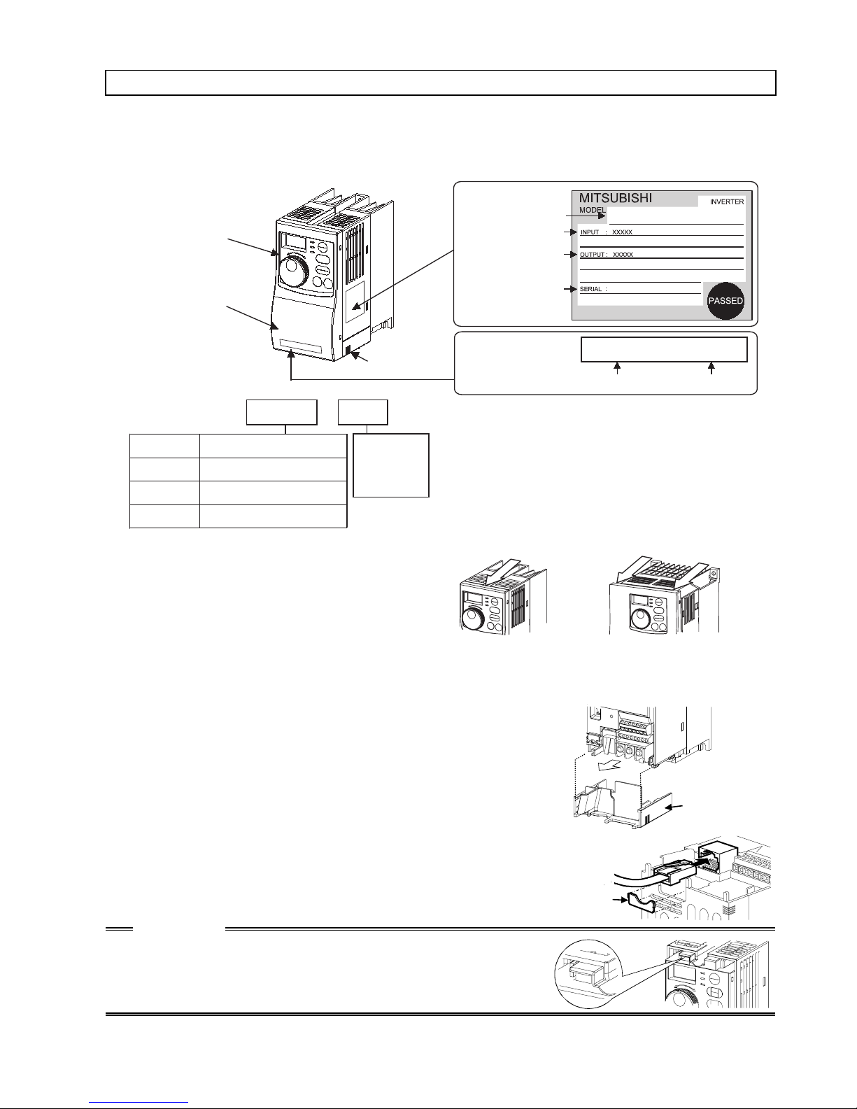
Product Checking and Parts Identification
A
A
Unpack the inverter and check the capacity plate on the front cover and the rating
plate on the inverter side face to ensure that the product agrees with your order and
the inverter is intact.
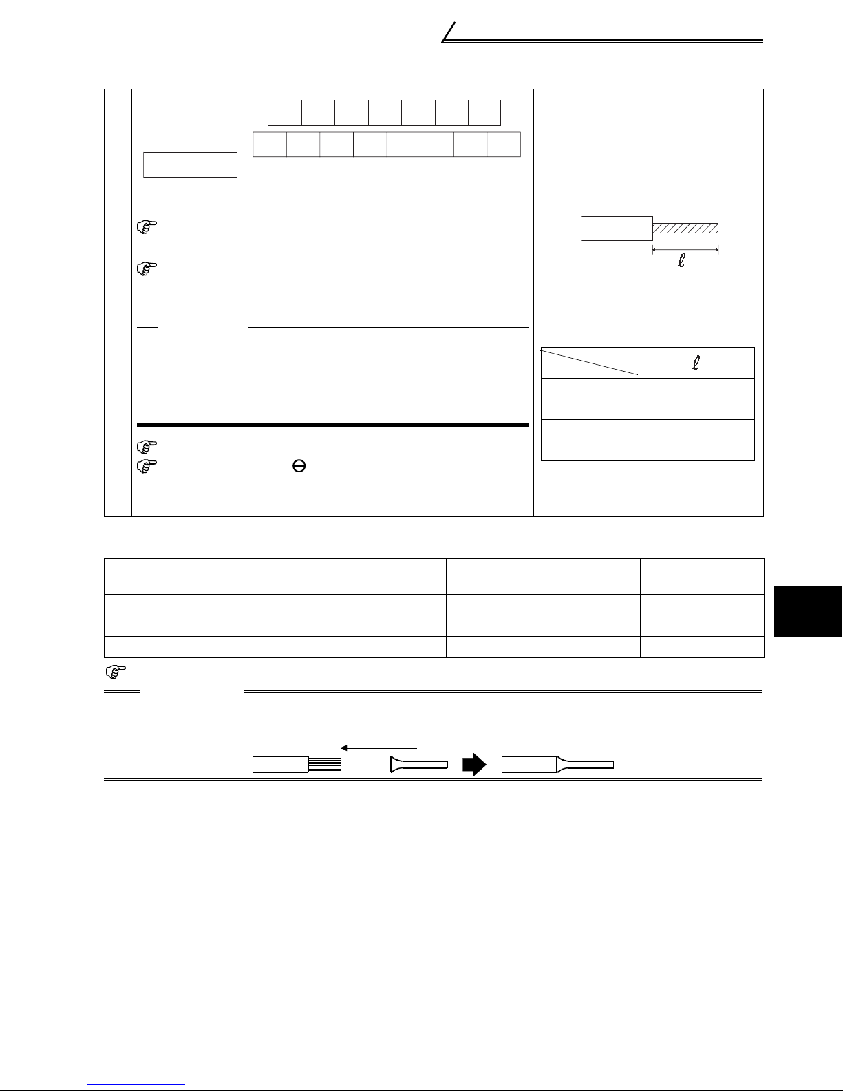
Parts and name plate
Operation panel
Front cover
Wiring cover
Inverter type
Symbol
S520E
S540E
S510WE
FR
Three-phase 200V class
Three-phase 400V class
Single-phase 100V class
S520E
-
Voltage class
0.1
- K - NA
Inverter
capacity
"kW"
z Removal and reinstallation of the
front cover
Remove the front cover by pulling it
toward you in the direction of arrow.
To reinstall, match the cover to the
inverter front and install it straight.
Rating plate
Inverter type
Input rating
Output rating
Serial number
Capacity plate
Inverter type Serial number
FR-S520E-0.1K to 0.75K-NA
FR-S510WE-0.1K to 0.4K-NA
FR-S520E-0.1K-NA XXXXXX
FR-S520E-0.1K-NA
FR-S520E-1.5K to 3.7K-N
FR-S540E-0.4K to 3.7K-N
FR-S510WE-0.75K-NA
z Removal and reinstallation of the wiring cover
The cover can be removed easily by pulling it toward
you.
To reinstall, fit the cover to the inverter along the guides.
z RS-485 communication connector
When using the RS-485 connector to wire the cable, you
can cut off the tab of the wiring cover to wire it. (Cutting off
the tab will provide protective structure IP10.)
CAUTION
The connector above the operation panel is for
manufacturer use. Do not touch it as doing so may
cause an electric shock.
Wiring cover
Tab
1
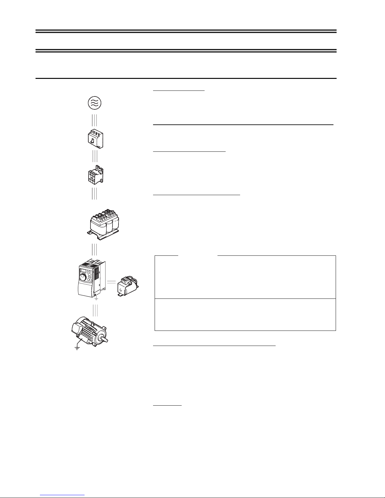
Basic configuration
1. CONNECTION OF PERIPHERAL DEVICES
1.1 Basic configuration
Power supply
Use within the permissible power supply
specifications of the inverter. (Refer to page 76.)
No-fuse breaker or earth leakage circuit breaker
The breaker must be selected carefully since an in-
(NFB)
or (ELB)
(MC)
AC reactor
(FR-HAL
/FR-BAL)
rush current flows in the inverter at power on.
Magnetic contactor
Install for your safety. Do not use this magnetic
contactor to start and stop the inverter. Doing so will
cause the inverter life to be shorten. (Refer to page
17.)
Installation of a reactor
A reactor must be used when the power harmonics
measure is taken, power factor is to be improved or
the inverter is installed near a large supply system
(500kVA or more and wiring distance within 10 m
(32.8 feet)).
Make the selection carefully.
Inverter
(FR-S500E)
Ground
Motor
Ground
DC reactor
(FR-HEL
/FR-BEL)
Inverter
The life of the inverter is influenced by ambient
temperature. Check the ambient temperature.
Epecially when mounting the inverter inside an
enclosure, take cautions of the ambient
temperature. (Refer to page 80.)
Wrong wiring might lead to damage of the inverter.
The control signal wires must be kept fully away
from the main circuit to protect them from noise.
(Refer to page 6.)
Devices connected to the output
Do not install a power factor correction capacitor,
surge suppressor or radio noise filter on the output
side of the inverter.
When installing a no-fuse breaker on the output side
of the inverter, contact each manufacturer for
selection of the no-fuse breaker.
Ground
To prevent an electric shock, always ground the
motor and inverter.
For reduction of induction noise from the power line
of the inverter, it is recommended to wire the ground
cable by returning it to the ground terminal of the
inverter.
(For details of noise reduction techniques, refer to
the instruction manual (detailed).)
2

Basic configuration
Selection of peripheral devices (selection changes with the power input
specifications of the inverter)
1) Three-phase 200V power input
Motor
Output
(kW
(HP))
0.1
(1/8)
0.2
(1/4)
0.4
(1/2)
0.75
(1)
1.5
(2)
2.2
(3)
3.7
(5)
Applied Inverter
Type
FR-S520E-0.1K-NA
FR-S520E-0.2K-NA
FR-S520E-0.4K-NA
FR-S520E-0.75K-NA
FR-S520E-1.5K-NA
FR-S520E-2.2K-NA
FR-S520E-3.7K-NA
No-fuse Breaker
(NFB *1, 4) or
Earth Leakage
Circuit Breaker
(ELB) (*2, 4)
30AF/5A S-N10 0.4 (*3) 0.4 (*3)
30AF/5A S-N10 0.4 (*3) 0.4 (*3)
30AF/5A S-N10 0.4 0.4
30AF/10A S-N10 0.75 0.75
30AF/15A S-N10 1.5 1.5
30AF/20A S-N10 2.2 2.2
30AF/30A
Magnetic
Contactor
(MC)
(Refer to
page 17)
S-N20,
S-N21
AC Reactor
FR-HALFR-BAL-
K
K
3.7 3.7
DC Reactor
FR-HELFR-BEL-
K
K
1
2) Three-phase 400V power input
Motor
Output
(kW
(HP))
0.4
(1/2)
0.75
(1)
1.5
(2)
2.2
(3)
3.7
(5)
Applied Inverter
Type
FR-S540E-0.4K-NA
FR-S540E-0.75K-NA
FR-S540E-1.5K-NA
FR-S540E-2.2K-NA
FR-S540E-3.7K-NA
No-fuse Breaker
(NFB *1, 4) or
Earth Leakage
Circuit Breaker
(ELB) (*2, 4)
30AF/5A S-N10 H0.4 H0.4
30AF/5A S-N10 H0.75 H0.75
30AF/10A S-N10 H1.5 H1.5
30AF/15A S-N10 H2.2 H2.2
30AF/20A
Magnetic
Contactor
(MC)
(Refer to
page 17)
S-N20,
S-N21
AC Reactor
FR-HAL-K
FR-BAL-K
H3.7 H3.7
DC Reactor
FR-HEL-K
FR-BEL-K
CONNECTION OF PERIPHERAL DEVICES
3

Basic configuration
3) Single-phase 100V power input
Motor
Output
(kW
(HP))
Applied Inverter
Type
(NFB *1, 4) or
Earth Leakage
Circuit Breaker
(ELB) (*2, 4)
No-fuse Breaker
0.1
(1/8)
0.2
(1/4)
0.4
(1/2)
0.75
(1)
FR-S510WE-0.1K-NA
FR-S510WE-0.2K-NA
FR-S510WE-0.4K-NA
FR-S510WE-0.75K-NA
30AF/10A S-N10 0.75
30AF/15A S-N10 1.5
30AF/20A
30AF/30A
*1. •Select the NFB according to the inverter power supply
capacity.
• Install one NFB per inverter.
Magnetic
Contactor
(MC)
(Refer to
page 17)
S-N20,
S-N21
S-N20,
S-N21
AC Reactor(*3)
FR-HALFR-BAL-
K
K
2.2
3.7
NFB
NFB INV
DC Reactor (*5)
FR-HELFR-BEL-
K
K
INV
*2. For installations in the United States or Canada, the circuit breaker must be inverse
time or instantaneous trip type.
*3. The power factor may be slightly lower.
*4. When the breaker on the inverter primary side trips, check for the wiring fault (short
circuit), damage to internal parts of the inverter, etc. Identify the cause of the trip,
then remove the cause and power on the breaker.
*5. The single-phase 100V power input model does not allow the DC reactor to be fitted.
IM
IM
4
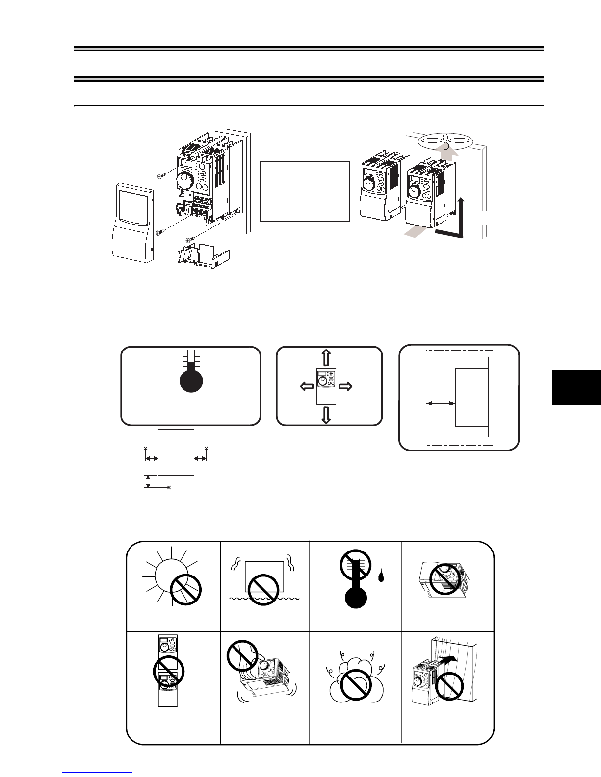
2. INSTALLATION METHOD
g
2.1 Installation of the inverter
Enclosure surface mounting Encasing multiple inverters
Fix the front
cover and wiring
cover after
removing them.
Leave enough clearances
and provide coolin
z Install the inverter under the following conditions.
measures.
Installation of the inverter
Vertical
When containing two or more
inverters, install them in parallel
and provide cooling measures.
Temperature: -10°C to 50°C
(14°F to 122°F)
Humidity: 90%RH maximum
5cm
5cm
(1.97inches)
Ambient temperature
and humidity
Measurement
position
Inverter
Measurement position
5cm
(1.97inches)(1.97inches)
Clearances (front)
1cm
(0.39inch)
or more
10cm
(3.94inches)
or more
These clearances are also
necessary for changing the
cooling fan. (
more is provided with a
cooling fan.
10cm
(3.94inches)
or more
1cm
(0.39inch)
or more
The 1.5K or
)
Clearances (side)
5cm
(1.97inches)
or more
Inverter
z Inverter consists of precision mechanical and electronic parts. Never install or
handle it in any of the following conditions as doing so could cause an operation
fault or failure.
Direct sunlight
Vibration
(5.9m/s
2
or more)
High temperature,
high humidity
Horizontal placement
2
INSTALLATION METHOD
Vertical mounting
(when mounted
inside enclosure)
Transportation
by holding front
cover or dial
Oil mist, flammable
gas, corrosive gas,
fluff, dust, etc.
5
Mounting to
combustible material
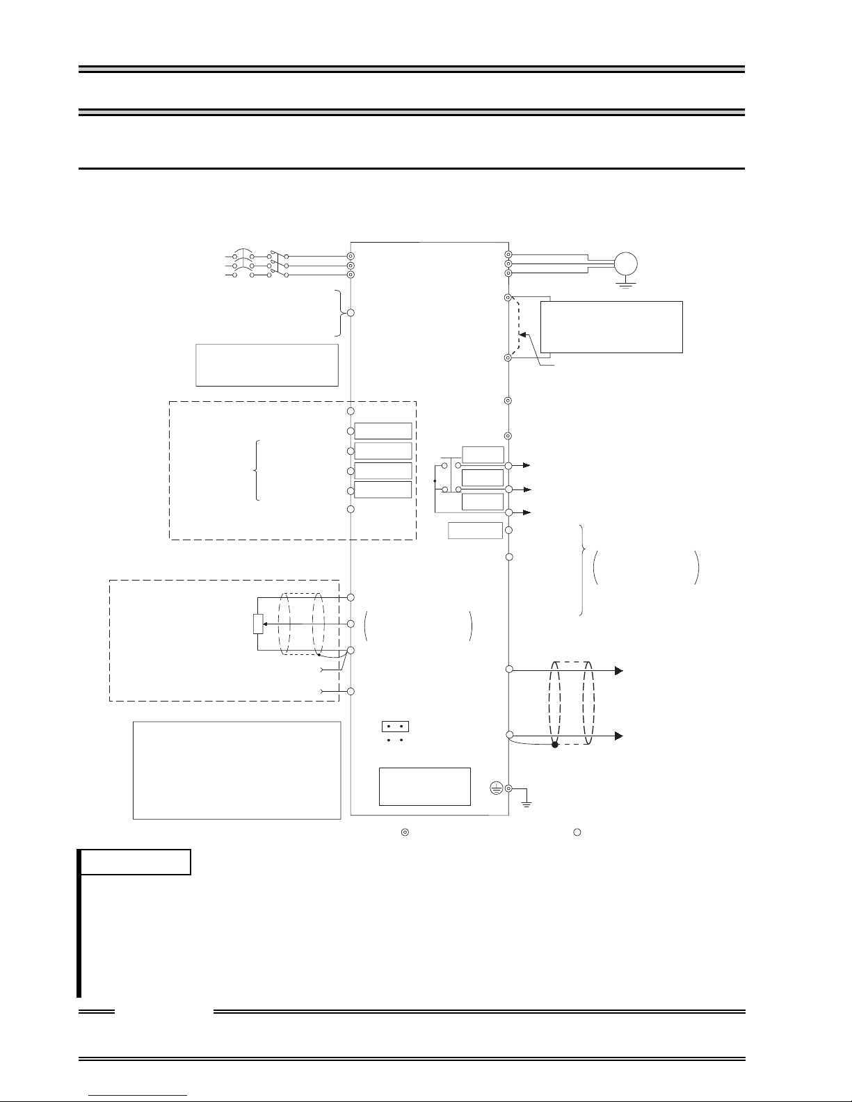
Terminal connection diagram
3. SPECIFICATIONS OF WIRING AND TERMINALS
3.1 Terminal connection diagram
z Three-phase 200V power input
z Three-phase 400V power input
NFB MC
Three-phase AC
power supply
External transistor common
24VDC power supply
Contact input common (source)
Take care not to short
terminals PC-SD.
Forward rotation start
Control input
signals
(No voltage
input allowed)
Frequency setting signals (Analog)
Frequency setting
potentiometer
1/2W1kΩ
Reverse rotation start
Multi-speed
selection
Contact input common
3
*4
1
Current input(-)
4 to 20mADC(+)
When using the current input as
the frequency setting signal, set
"4" in any of Pr. 60 to Pr. 63 (input
terminal function selection), assign
AU (current input selection) to any
of terminals RH, RM, RL and STR
and turn on the AU signal.
High speed
Middle speed
Low speed
2
Inverter
R/L1
S/L2
T/L3
PC
STF
STR
*5
*5
RH
*5
RM
RL
*5
SD
10
(+5V)
0 to 5VDC
2
0 to 10VDC
5
(Common)
4
(4 to 20mADC)
SINK
*3
SOURCE
RS-485
Connector
*1
*2
*6
*6
*6
*6
RUN
Selected
U
V
W
P1
P/+
N/-
PR
A
B
C
SE
AM
Running
Open
collector
output
common
5
Motor
IM
Ground
DC reactor
(FR-HEL/BEL: Option)
Jumper:
jumper when DC reactor
is connected.
Alarm output
Remove this
Operation status
output
Open collector
outputs
(+)
Analog signal
output
(0 to 5VDC)
(-)
Ground
REMARKS
*1. The N/- terminal is not provided for the FR-S520E-0.1K to 0.75K-NA.
*2. The PR terminal is provided for the FR-S520E-0.4K to 3.7K-NA. (not used)
*3. You can switch the position of sink and source logic. (Refer to page 15.)
*4. When the setting potentiometer is used frequently, use a 2W1kΩ potentiometer.
*5. The terminal functions change with input terminal function selection (Pr. 60 to Pr. 63). (Refer to page 54.)
(RES, RL, RM, RH, RT, AU, STOP, MRS, OH, REX, JOG, X14, X16, (STR) signal selection)
*6. The terminal function changes according to the setting of output terminal function selection (Pr. 64, Pr. 65).
(Refer to page 54.) (RUN, SU, OL, FU, RY, Y12, Y13, FDN, FUP, RL, Y93, Y95, LF, ABC signal selection)
CAUTION
To prevent a malfunction due to noise, keep the signal cables more than 10cm away
from the power cables.
Control circuit terminalMain circuit terminal
6

z Single-phase 100V power input
Main circuit
NFB
Power
supply
MC
R/L1
S/L
Motor
U
2
V
W
IM
Ground
REMARKS
•To ensure safety, connect the power input to the inverter via a magnetic contactor and earth leakage
circuit breaker or no-fuse breaker, and use the magnetic contactor to switch power on-off.
•The output is three-phase 200V.
3.2 Main circuit
3.2.1 Explanation of main circuit terminals
Term inal
Symbol
R/L1, S/L2,
T/L3 (*1)
Terminal Name Description
AC power input
Connect to the commercial power supply.
U, V, W Inverter output
PR (*2)
P/+, N/−
P/+, P1
Brake unit
connection
DC reactor
connection
Ground
*1. When using single-phase power input, terminals are R/L1 and S/L2.
*2. The PR terminal is provided for the FR-S520E-0.4K to 3.7K-NA.
Connect a three-phase squirrel-cage motor.
Do not use PR terminal.
Connect the brake unit (BU), power regeneration
common converter (FR-CV) or high power factor
converter (FR-HC). (The N/- terminal is not provided for
the FR-S520E-0.1K to 0.75K-NA.)
Remove the jumper across terminals P - P1 and connect
the optional DC reactor (FR-HEL(-H)/FR-BEL(-H)).
(The single-phase 100V power input model cannot be
connected.)
For grounding the inverter chassis. Must be grounded.
3
SPECIFICATIONS OF WIRING AND TERMINALS
7
Main circuit
r
r
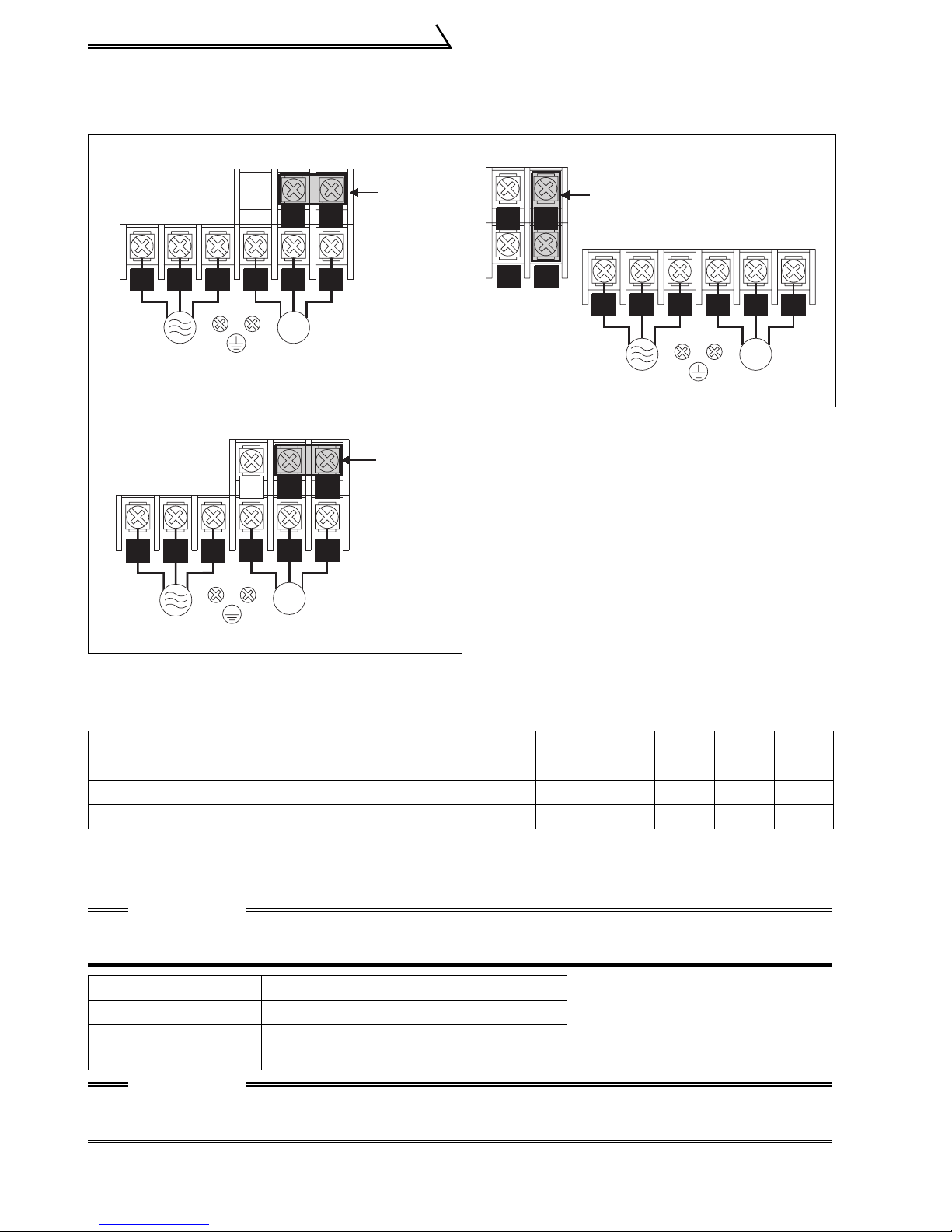
3.2.2 Terminal block layout
1) Three-phase 200V power input
• FR-S520E-0.1K, 0.2K-NA • FR-S520E-1.5K, 2.2K, 3.7K-NA
P/+
P1
R/L1 S/L2 T/L3
Power supply
U V W
IM
Motor
• FR-S520E-0.4K, 0.75K-NA
P1
IM
P/+
R/L1 S/L2
T/L3
Power supply
PR
U V W
Motor
Jumpe
Jumpe
N/-
PR
P/+
P1
Jumper
R/L1 S/L2 T/L3
Power supply
U V W
IM
Motor
<When single-phase power is applied to three-phase power input inverter
(FR-S520E-0.1K to 3.7K-NA only)>
•Reduce the output current.
FR-S520E- K-NA inverter 0.1 0.2 0.4 0.75 1.5 2.2 3.7
Rated output current (A) 0.4 0.8 1.5 2.5 4.0 5.0 7.0
Power supply capacity (kVA) 0.4 0.8 1.5 2.5 4.5 5.5 9.0
AC input current (A) 1.1 2.4 4.5 6.4 11.2 12.9 17.4
•Set m9 (Pr. 637) "current detection filter".
Setting "801" in the manufacturer setting parameter C8 enables you to set the m9
parameter.
CAUTION
Parameters other than m9 can also be made to be displayed, but never alter these
since they are manufacturer setting parameters.
m9 Setting Description
0 Single-phase power input
- - -
(Factory setting)
Three-phase power input
CAUTION
Always return the C8 parameter to 0 (factory setting) after you have finished the
setting of m9.
8
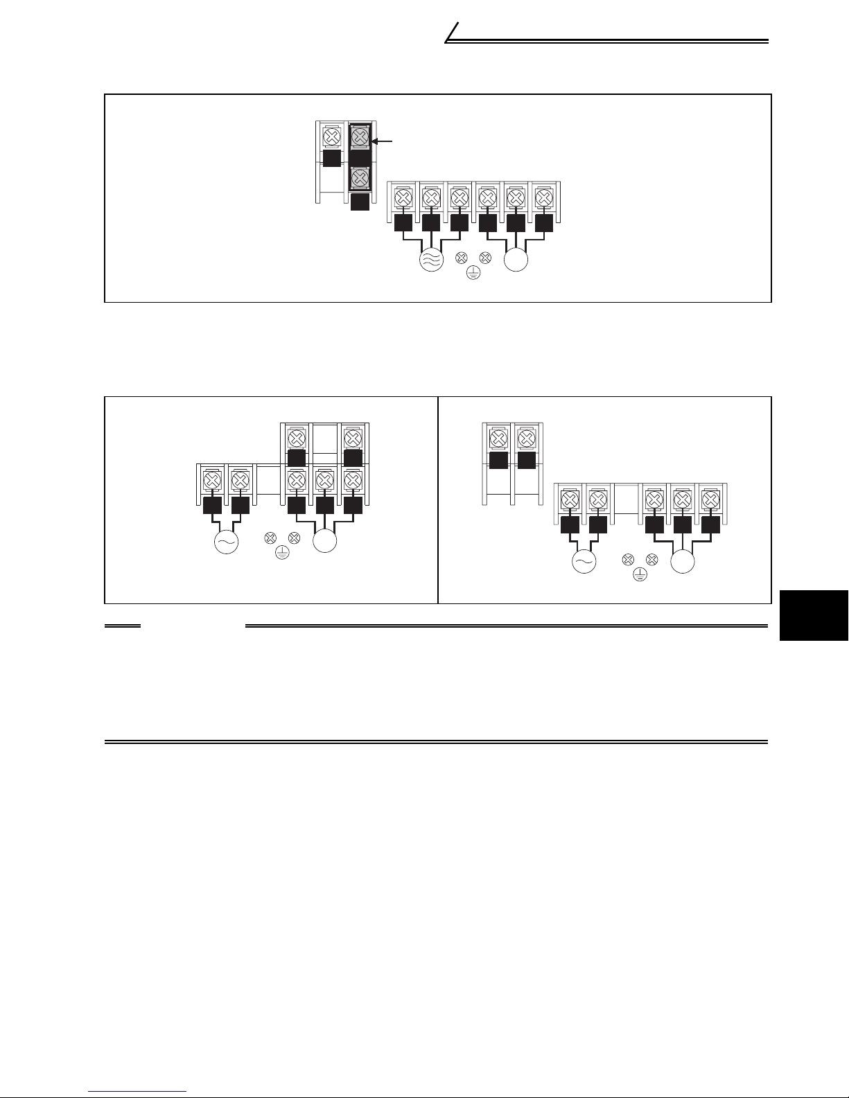
2) Three-phase 400V power input
Main circuit
• FR-S540E-0.4K, 0.75K, 1.5K, 2.2K, 3.7K
-NA
Jumper
P/+
N/-
P1
R/L1 S/L2 T/L3
Power supply
U V W
IM
Motor
3) Single-phase 100V power input
• FR-S510WE-0.1K, 0.2K, 0.4K-NA • FR-S510WE-0.75K-NA
R/L1 S/L2
Power supply
P/+N/-
U V W
IM
Motor
N/-
P/+
R/L1 S/L2
Power supply
U V W
IM
Motor
CAUTION
•Make sure the power cables are connected to the R/L1, S/L2, T/L3 of the inverter.
Never connect the power cable to the U, V, W of the inverter. (Phase need not be
matched)
•Connect the motor to U, V, W. At this time, turning on the forward rotation switch
(signal) rotates the motor in the counterclockwise direction when viewed from the
motor shaft.
3
SPECIFICATIONS OF WIRING AND TERMINALS
9
Main circuit
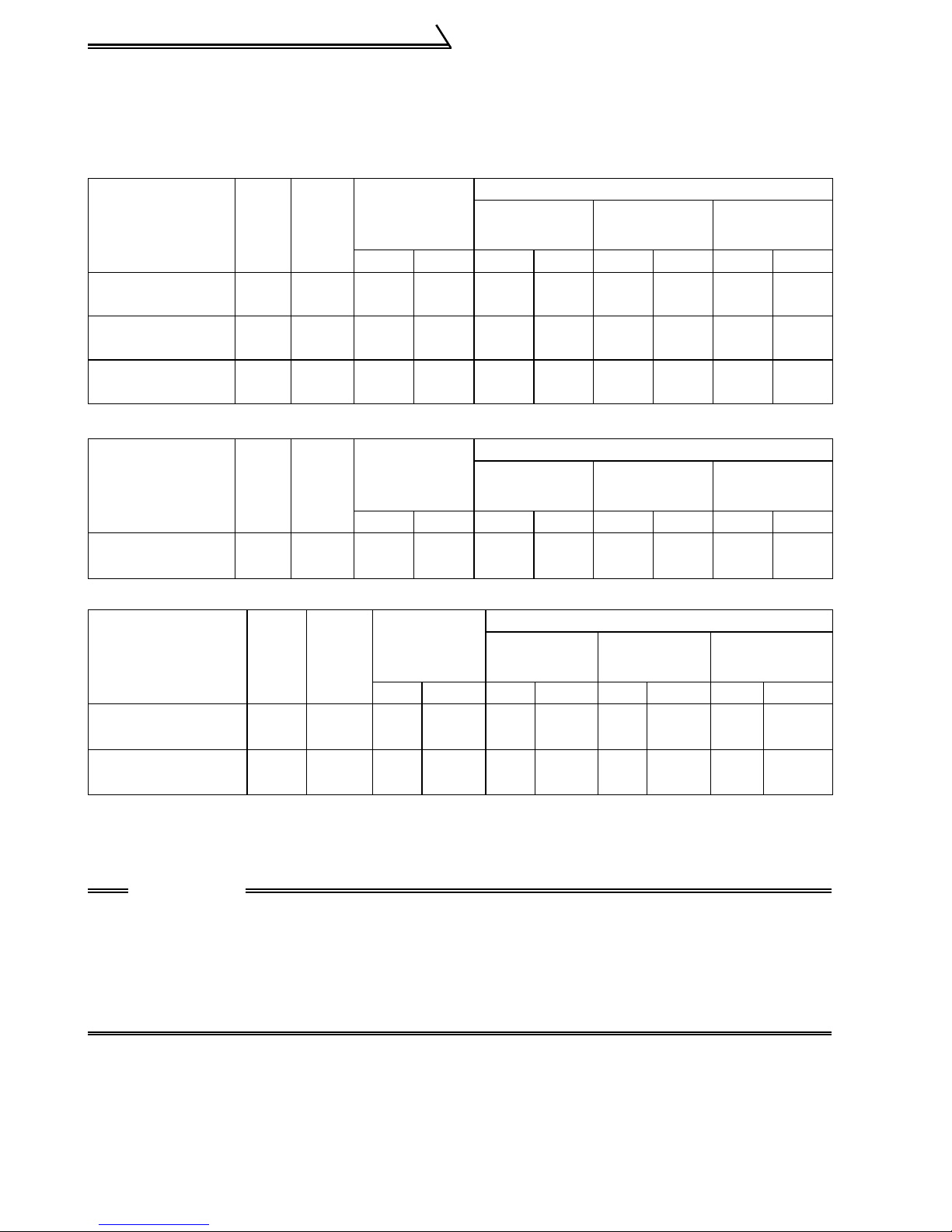
3.2.3 Cables, wiring length, and crimping terminals
The following table indicates a selection example for the wiring length of 20m (65.62
feet).
1) Three-phase 200V power input
Cable Size
AWG
R, S, T
U, V, W
Cable Size
AWG
PVC cable
(mm
R, S, T
U, V, W
PVC cable
(mm
2
)
2
)
Applied Inverter
FR-S520E-0.1K
to 0.75K-NA
FR-S520E-
1.5K, 2.2K-NA
FR-S520E-
3.7K-NA
Ter-
minal
Screw
size
M3.5 1.2 2-3.5 2-3.5 2 2 14 14 2.5 2.5
M4 1.5 2-4 2-4 2 2 14 14 2.5 2.5
M4 1.5 5.5-4 5.5-4 3.5 3.5 12 12 4 2.5
Tightening
Torque
⋅
m
N
Crimping
R, S, T U, V, W
2) Three-phase 400V power input
Applied Inverter
FR-S540E-0.4K
to 3.7K-NA
Ter-
minal
Screw
size
M4 1.5 2-4 2-4 2 2 14 14 2.5 2.5
Tightening
Torque
⋅
m
N
Crimping
R, S, T U, V, W R, S, T U, V, W R, S, T U, V, W R, S, T U, V, W
Termi nal
Termi nal
HIV cable
(mm
R, S, T
HIV cable
(mm2)
2
)
U, V, W
3) Single-phase 100V power input
Cable Size
AWG
PVC cable
2
(mm
)
Applied Inverter
FR-S510WE-
0.1K
to 0.4K-NA
FR-S510WE-0.75KNA
Termi -
nal
Screw
size
M3.5 1.2 2-3.5 2-3.5 2 2 14 14 2.5 2.5
M4 1.5 5.5-4 2-4 3.5 2 12 14 4 2.5
Tightening
Torqu e
⋅
m
N
Crimping
Terminal
HIV cable
2
(mm
)
R, S U, V, W R, S U, V, W R, S U, V, W R, S U, V, W
z Wiring length
100m (328.08 feet) maximum. (50m (164.04 feet) maximum for the FR-S540E-
0.4K-NA.)
CAUTION
•When the wiring length of the 0.1K and 0.2K of the three-phase 200V and
single-phase 100V class and the 0.4K and 0.75K of the three-phase 400V class
is 30m (98.43 feet) or more, set the carrier frequency to 1kHz.
•When automatic torque boost is selected in Pr. 98 "automatic torque boost
selection (motor capacity)", the wiring length should be 30m (98.43 feet)
maximum. (Refer to page 57.)
10
3.3 Control circuit
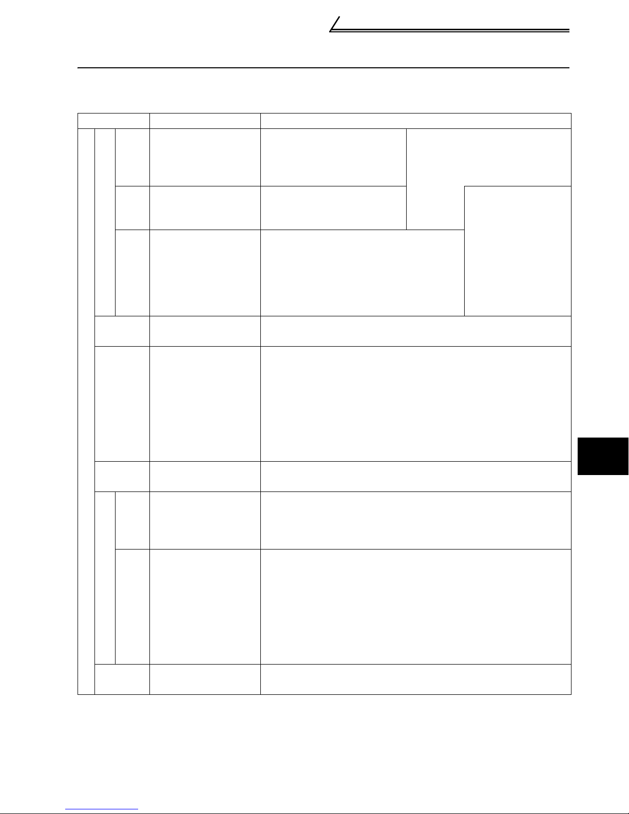
3.3.1 Explanation of control circuit terminals
Symbol Terminal Name Definition
When the STF and STR
signals are turned on
simultaneously, the stop
command is given.
Input signals
STF
STR
RH
Contact input
RM
RL
SD
(*1)
PC
(*1)
10
Frequency setting
5
Forward rotation
start
Reverse rotation
start
Multi-speed
selection
Contact input
common (sink)
External
transistor
common, 24VDC
power supply,
contact input
common (source)
Frequency setting
power supply
Frequency setting
2
(voltage signal)
Frequency setting
4
(current signal)
Frequency setting
input common
Turn on the STF signal to
start forward rotation and
turn it off to stop.
Turn on the STR signal to
start reverse rotation and
turn it off to stop.
Turn on the RH, RM and RL signals in
appropriate combinations to select
multiple speeds.
The priorities of the speed commands
are in order of jog, multi-speed setting
(RH, RM, RL, REX) and AU.
Common to the contact input terminals (STF, STR, RH, RM,
RL). (*6)
When connecting the transistor output (open collector output),
such as a programmable controller (PLC), connect the positive
external power supply for transistor output to this terminal to
prevent a malfunction caused by undesirable currents.
This terminal can be used as a 24VDC, 0.1A power output
across terminals PC-SD.
When source logic has been selected, this terminal serves
as a contact input common.
5VDC, Permissible load current 10mA.
Inputting 0 to 5VDC (or 0 to 10V) provides the maximum output
frequency at 5V (10V) and makes input and output proportional.
Switch between 5V and 10V using Pr. 73 "0-5V, 0-10V selection".
Input resistance 10kΩ. Maximum permissible input voltage 20V
Input 4 to 20mADC. It is factory set at 0Hz for 4mA and at
60Hz for 20mA.
Maximum permissible input current 30mA. Input resistance
approximately 250Ω.
Turn ON signal AU for current input.
Turning the AU signal on makes voltage input invalid. Use any of
Pr. 60 to Pr. 63 (input terminal function selection) to set the AU
signal.
Common terminal for the frequency setting signals
(terminal 2, 4) and indicator connection (terminal AM). (*6)
Control circuit
The terminal
functions change
with input terminal
function selection
(Pr. 60 to Pr.63).
(*3)
3
SPECIFICATIONS OF WIRING AND TERMINALS
11

Control circuit
Symbol Terminal Name Definition
Changeover contact output indicates
that the inverter protective function has
Output signals
A
B
C
RUN
Open collector
SE
AM
Indicator
Alarm output
Inverter
running
Open collector
common
Analog signal
output
activated and the output stopped.
230VAC 0.3A, 30VDC 0.3A. Alarm:
discontinuity across B-C (continuity
across A-C), Normal: continuity across
B-C (discontinuity across A-C).(*5)
Switched low when the inverter output
frequency is equal to or higher than the
starting frequency (factory set to 0.5Hz
variable). Switched high during stop or
DC injection brake operation. (*2)
Permissible load 24VDC 0.1A (a
voltage drop is 3.4V maximum when
the signal is on)
Common terminal for inverter running terminal RUN.
The output signal across terminals AM-5 is factory set to about
5VDC at 60Hz and is proportional to the corresponding output
frequency.
Frequency permissible load current 1mA
Output signal 0 to 5VDC
The function of the
terminals changes
according to the
output terminal
function selection
(Pr. 64, Pr.65).
(*4)
(*6)
Using the parameter unit connection cable (FR-CB201 to
205), the parameter unit (FR-PU04) can be connected.
Communication operation can be performed using RS-485.
For details of RS-485 communication, refer to the
separately available instruction manual (detailed).
——
RS-485
connector
Communication
*1. Do not connect terminals SD and PC each other or to the ground.
For sink logic (factory setting), terminal SD acts as the common terminal of contact input.
For source logic, terminal PC acts as the common terminal of contact input. (Refer to the
separately available instruction manual (detailed) for switching method.)
*2. Low indicates that the open collector output transistor is on (conducts). High indicates
that the transistor is off (does not conduct).
*3. RL, RM, RH, RT, AU, STOP, MRS, OH, REX, JOG, RES, X14, X16, (STR) signal
selection (Refer to page 54.)
*4. RUN, SU, OL, FU, RY, Y12, Y13, FDN, FUP, RL, Y93, Y95, LF, ABC signal selection
(Refer to page 54.)
*5. To be compliant with the European Directive (Low Voltage Directive), the operating
capacity of relay outputs (A, B, C) should be 30VDC 0.3A.
*6. Terminals SD, SE and 5 are isolated from each other. Do not ground.
12
Control circuit
3.3.2 Arrangement and wiring of control circuit terminals
PC
SE RUN 10 2 5 4
SD
AB
SD STF STR RM RH
C
RL AM
Loosen the terminal screw and insert the cable into the
terminal.
Cable stripping size
Screw size: M3 (A, B, C terminals),
M2 (other than the above)
Tightening torque: 0.5N•m to 0.6N•m (A, B, C terminals)
0.22N•m to 0.25N•m (other than the
above)
CAUTION
Wire the stripped cable after
twisting it to prevent it from
becoming loose.
In addition, do not solder it. *
Undertightening can cause cable
disconnection or malfunction. Overtightening
can cause a short circuit or malfunction due
to damage to the screw or unit.
Cable size: 0.3mm
Screwdriver: Small flat-blade screwdriver
Control circuit terminal block
2
to 0.75mm
2
ABC
terminals
Other than
the above
Tip thickness: 0.4mm (0.02 inch)
Tip width: 2.5mm (0.10 inch)
*Information on bar terminals
Introduced products (as of August, 2005): Phoenix Contact Co.,Ltd.
Terminal Screw Size
M3 (A, B, C terminal)
M2 (Other than the above) Al 0.5-6WH A 0.5-6 0.3 to 0.5
Bar Terminal Model
(With Insulation Sleeve)
Al 0.5-6WH A 0.5-6 0.3 to 0.5
Al 0.75-6GY A 0.75-6 0.5 to 0.75
Bar Terminal Model
(Without Insulation Sleeve)
6mm
(0.24 inch)
5mm
(0.20 inch)
Wire Size (mm2)
3
Bar terminal crimping tool: CRIMPFOX ZA3 (Phoenix Contact Co., Ltd.)
CAUTION
When using the bar terminal (without insulation sleeve), use care so that the
twisted wires do not come out.
SPECIFICATIONS OF WIRING AND TERMINALS
13

Control circuit
3.3.3 Connection to RS-485 connector
(1) When connecting the parameter unit
Use the optional FR-CB2 . When the parameter unit (FR-PU04) is used,
operation from the operation panel is not accepted. ( is valid)
(2) RS-485 communication
Using the RS-485 connector, you can perform communication operation from a
personal computer etc. By connecting the RS-485 connector to computers such
as personal computer and FA with a communication cable, you can run/monitor
the inverter and read/write parameter values using a user program. For further
details, refer to the instruction manual (detailed).
· Conforming standard: EIA-485 (RS-485)
· Transmission format: Multi-drop link
· Communication speed: Maximum 19200 bps
· Overall extension: 500m (1640.42 feet)
CAUTION
Do not plug the connector to a computer LAN board, fax modem socket, telephone modular connector etc. As they are different in electrical specifications,
the inverter may be damaged.
STOP
RESET
14
Control circuit
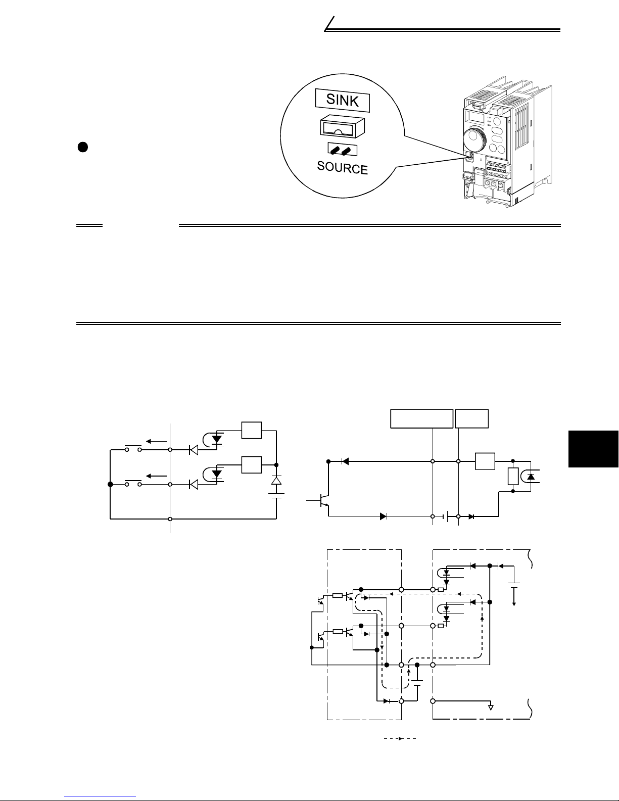
3.3.4 Changing the control logic
The input signals are set to sink
logic.
To change the control logic, the
jumper connector under the setting
dial must be moved to the other
position.
Change the jumper connector
position using tweezers, a pair of
long-nose pliers etc.
Change the jumper connector
position before switching power on.
CAUTION
•Make sure that the front cover is installed securely.
•The front cover is fitted with the capacity plate and the inverter unit with the
rating plate. Since these plates have the same serial numbers, always replace
the removed cover onto the original inverter.
•The sink-source logic change-over jumper connector must be fitted in only
one of those positions. If it is fitted in both positions at the same time, the
inverter may be damaged.
1) Sink logic type
• In this logic, a signal switches on when a current flows from the corresponding signal
input terminal.
Terminal SD is common to the contact input signals. Terminal SE is common to the
open collector output signals.
Power supply
STF
STR
SD
• Connecting a positive terminal of the
R
R
external power supply for transistor
output to terminal PC prevents a
malfunction caused by an undesirable
current. (Do not connect terminal SD
AY40
transistor
output module
1
2
RUN
SE
STF
STR
AX40Inverter
1
R
R
9
24VDC
Inverter
24VDC
(SD)
of the inverter with terminal 0V of the
external power supply. When using
terminals PC-SD as a 24VDC power
supply, do not install an external
power supply in parallel with the
inverter. Doing so may cause a
9
9
10
24VDC SD
PC
malfunction in the inverter due to an
undesirable current.)
Current flow
3
SPECIFICATIONS OF WIRING AND TERMINALS
15
Control circuit
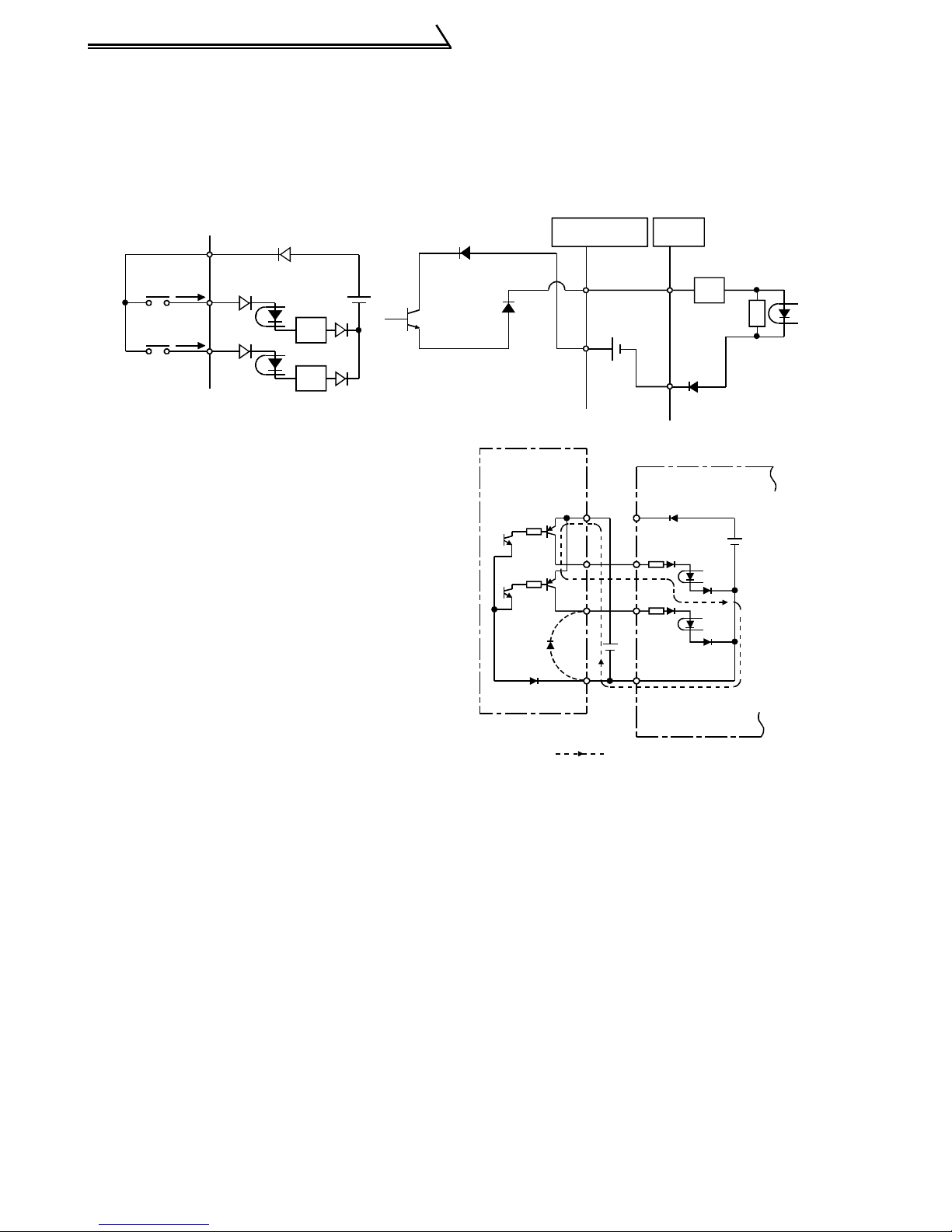
2) Source logic type
• In this logic, a signal switches on when a current flows into the corresponding signal
input terminal.
Terminal PC is common to the contact input signals. For the open collector output
signals, terminal SE is a positive external power supply terminal.
PC
Power
supply
STF
STR
R
R
• Connecting the 0V terminal of the
external power supply for transistor
output to terminal SD prevents a
malfunction caused by an undesirable
current.
AY80
transistor
output module
10
Inverter
RUN
SE
24VDC
9
1
2
PC
STF
STR
24VDC
SD
AX80
1
R
R
9
Inverter
24VDC
(SD)
Current flow
16
Control circuit
r
3.3.5 Power-off and magnetic contactor (MC)
(1) Inverter input side magnetic contactor (MC)
On the inverter's input side, it is recommended to provide an MC for the following
purposes. (Refer to page 3 for selection)
1) To release the inverter from the power supply when the inverter protective function
is activated or the drive becomes faulty (e.g. emergency stop operation)
2) To prevent any accident due to an automatic restart at restoration of power after an
inverter stop made by a power failure
3) To rest the inverter for an extended period of time
The control power supply for inverter is always running and consumes a little power.
When stopping the inverter for an extended period of time, powering off the inverter
will save power slightly.
4) To separate the inverter from the power supply to ensure safe maintenance and
inspection work
The inverter's input side MC is used for the above purpose, select class JEM1038AC3 for the inverter input side current when making an emergency stop during
normal operation.
REMARKS
The MC may be switched on/off to start/stop the inverter. However, since repeated inrush
currents at power on will shorten the life of the converter circuit (switching life is about 100,000
times), frequent starts and stops must be avoided. Turn on/off the inverter start controlling
terminals (STF, STR) to run/stop the inverter.
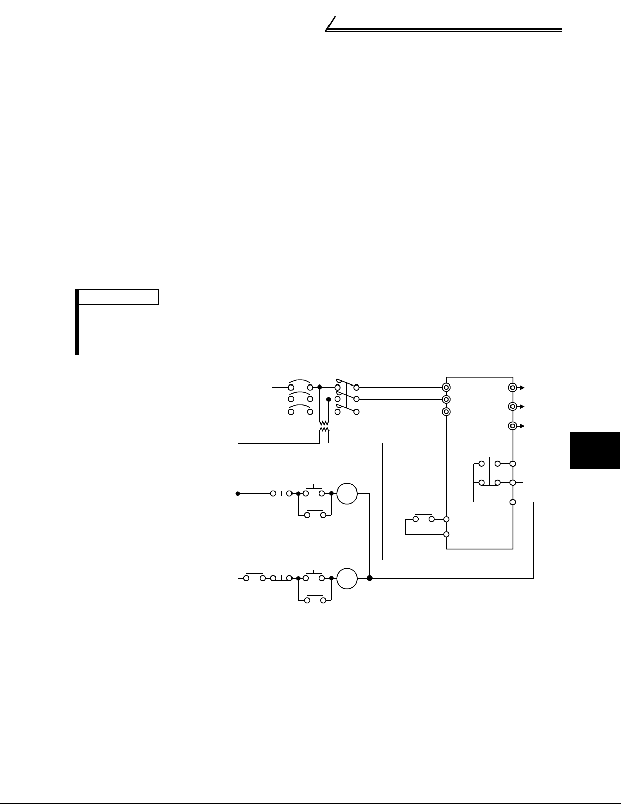
As shown on the right,
always use the start signal
(ON or OFF across
terminals STF or STR-SD)
to make a start or stop.
*1. When the power supply
is 400V class, install a
step-down transformer.
Power
supply
Operation ready
NFB
OFF
Start/Stop
ON
MC
MC
T (*1)
MC
RA
R/L1
S/L2
T/L3
Inverter
STF(STR)
SD
U
V
W
To
moto
A
B
C
3
(2) Handling of output side magnetic contactor
In principle, do not provide a magnetic contactor between the inverter and motor and
switch it from off to on during operation. If it is switched on during inverter operation, a
large inrush current may flow, stopping the inverter due to overcurrent shut-off. When
an MC is provided for switching to the commercial power supply, for example, switch it
on/off after the inverter and motor have stopped.
MC
Operation
OFF
RA
Inverter Start/Stop Circuit Example
RA
17
SPECIFICATIONS OF WIRING AND TERMINALS
Step of operation
Step of operation
p
4. DRIVE THE MOTOR
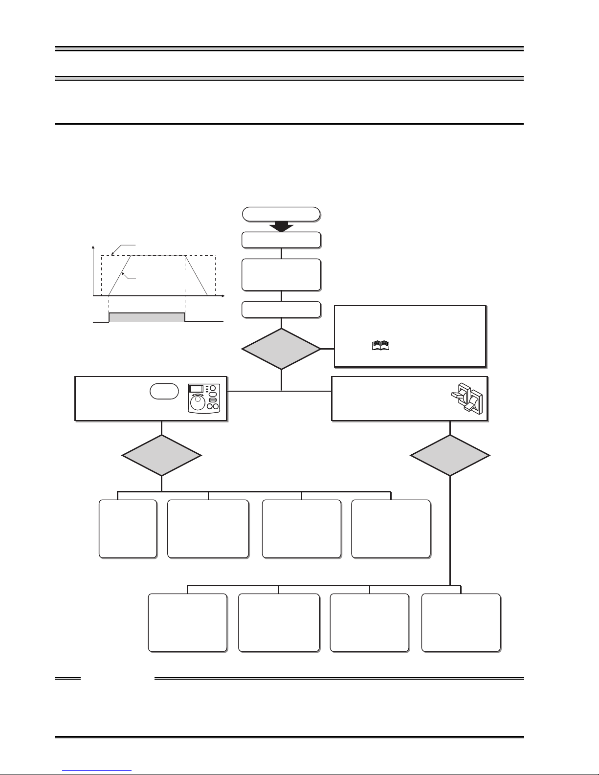
4.1 Step of operation
The inverter needs frequency command and start command. Turning the start
command on start the motor rotating and the motor speed is determined by the
frequency command.
Refer to the flow chart below to perform setting.
Step of operation
o
(Hz)
Frequency
Start
command
Start command with
on the operation panel (PU)
Set from the
operation
panel.
Frequency command
Inverter output
frequency
ON
How to
give a frequency
command?
(PU)
Time
(S)
RUN
-+
Change frequency
with ON/OFF switches
connected to terminals
(multi-speed setting)
(External)
Installation/mounting
Wiring of the power
supply and motor
System examination
How
to give a start
command?
Perform frequency
setting by a voltage
output device
(Connection across
terminals 2-5)
(External)
{Refer to page 5}
{Refer to page 8}
Start command using the RS-485
connector of the inverter
(Communication)
Refer to Instruction Manual
(detailed)
Connect a switch, relay, etc.
to the control circuit
terminal block of the inverter
to give a start command. (External)
Perform frequency
setting by a current
output device
(Connection across
terminals 4-5)
(External)
{Refer to page 21} {Refer to page 23} {Refer to page 25} {Refer to page 26}
How to
give a frequency
command?
Set from the
operation panel
(PU)
{Refer to page 28} {Refer to page 30} {Refer to page 32} {Refer to page 34}
CAUTION
Check the following items before powering on the inverter.
•Check that the inverter is installed correctly in a correct place. (Refer to page 5)
•Check that wiring is correct. (Refer to page 6)
•Check that no load is connected to the motor.
Change of frequency
with ON/OFF switches
connected to terminals
(multi-speed setting)
(External)
18
Perform frequency
setting by a voltage
output device
(Connection across
terminals 2-5)
(External)
Perform frequency
setting by a current
output device
(Connection across
Terminals 4-5)
(External)
4.2 Run and operation
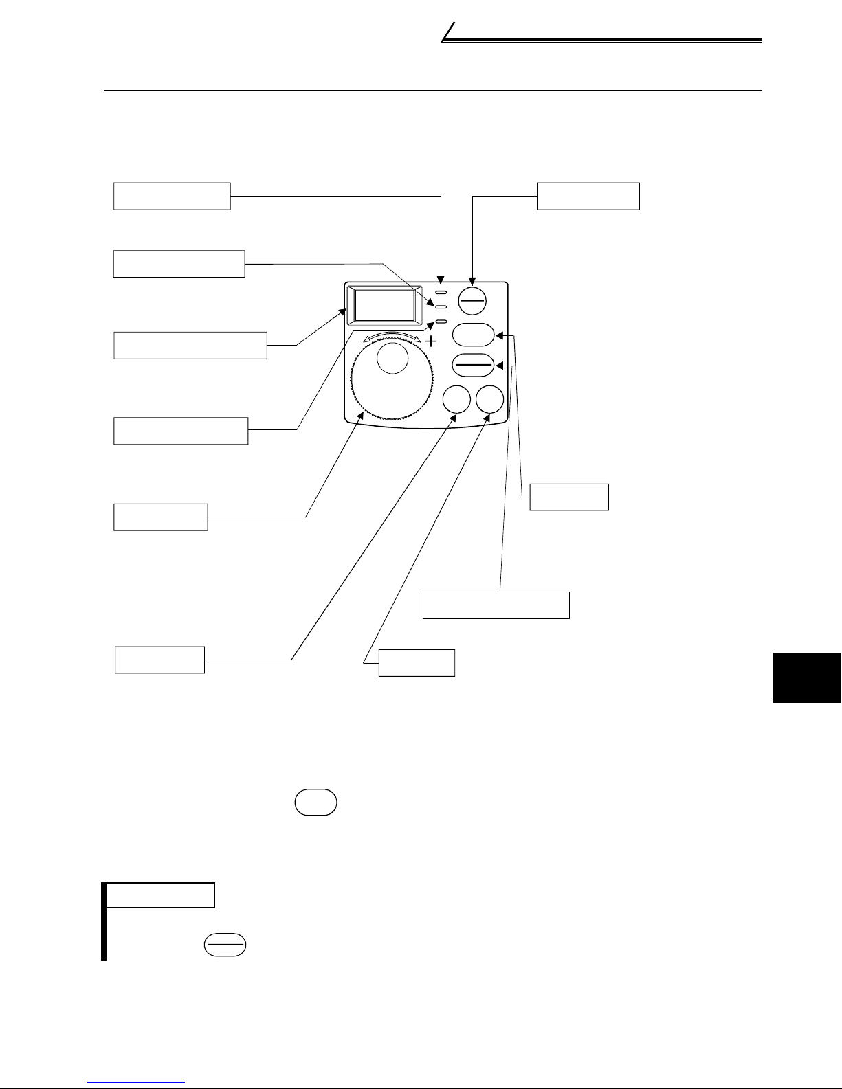
4.2.1 Parts of the operation panel
The operation panel cannot be removed from the inverter.
Run and operation
RUN indication
Turns on/flickers* to indicate operation.
PU indication **
Lit to indicate the PU
operation mode.
3-digit monitor LED
Shows the frequency,
parameter number, etc.
EXT indication **
Lit to indicate the external
operation mode.
Setting dial
(Setting dial: Mistubishi inverter's dial)
Used to change the frequency
setting and parameter values.
This dial cannot be removed.
PU/EXT Key
Used to switch between the
PU and external operation
mode.When using the external
RUN
PU
EXT
PU
EXT
RUN
operation mode (operation
using the separately
connected frequency setting
potentiometer and start
signal), press this key to
STOP
RESET
light up the EXT indication.
(Change the Pr. 79 value to
MODE SET
use the combined mode.)
PU: PU operation mode
EXT: External operation mode
RUN Key
Used to give the forward
rotation operation command.
Use Pr. 17 to set reverse
operation.
STOP/RESET Key
Used to stop operation or reset an alarm.
MODE Key
Used to change the setting mode.
SET Key
Used to define each setting.
* RUN indication
On: Indicates that forward rotation operation is being performed.
Slow flickering (1.4s cycle): Indicates reverse rotation
Fast flickering (0.2s cycle): Indicates that operation is not being performed
but the was pressed or the start command was given.
RUN
** PU/EXT indication
Flickers slowly in the computer link operation mode.
REMARKS
•When the parameter unit (FR-PU04) is used, operation from the operation panel is not
accepted. ( is valid)
STOP
RESET
4
DRIVE THE MOTOR
19
Run and operation
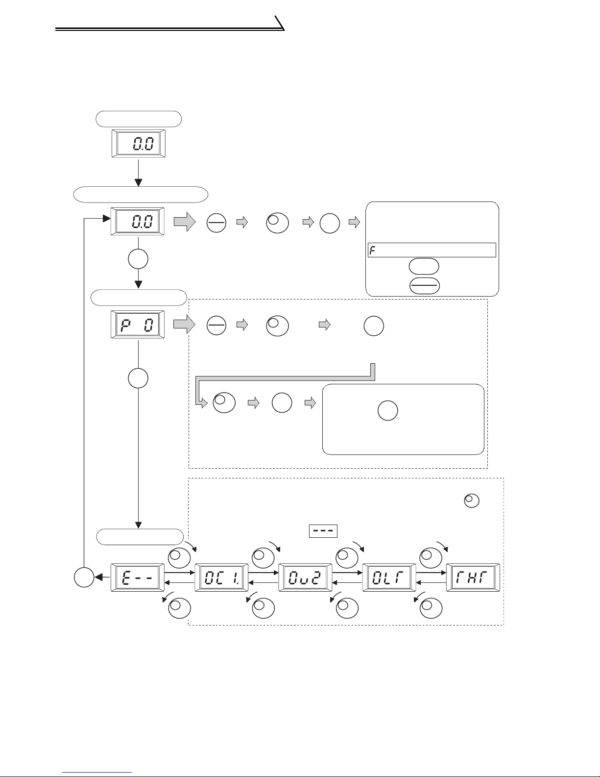
4.2.2 Basic operation
The following explains the outline of operation. (factory setting)
<Basic operation> (factory setting)
At powering on
Monitor/frequency setting
Return
Press
MODE
MODE
key.
Parameter setting
[Parameter setting change]
Press
MODE
MODE
key.
Turn the
setting dial
to change
value.
[Operation panel is used for operation]
PU
EXT
Press
PU/EXT
key.
Turn the
setting dial
to match
SET
Press
SET key
frequency.
PU
EXT
Press
PU/EXT
key.
Turn the setting
dial to match
frequency.
SET
After setting is completed,
SET
Press SET key to
show present setting.
press the once to show
Press SET
key to
complete
alarm history, or twice to
show frequency setting screen.
setting.
Frequency setting has
been written and
completed!!
and frequency flickers.
Press to start.
Press to stop.
MODE
RUN
STOP
RESET
[Operation for displaying alarm history]
Four past alarms can be displayed with the setting dial .
(The latest alarm is ended by ".".)
Alarm history
MODE
When no alarm exists, is displayed.
Press MODE key.
20
Operation by the start command from the operation panel
(PU operation mode)
4.3 Operation by the start command from the operation panel (PU operation mode)
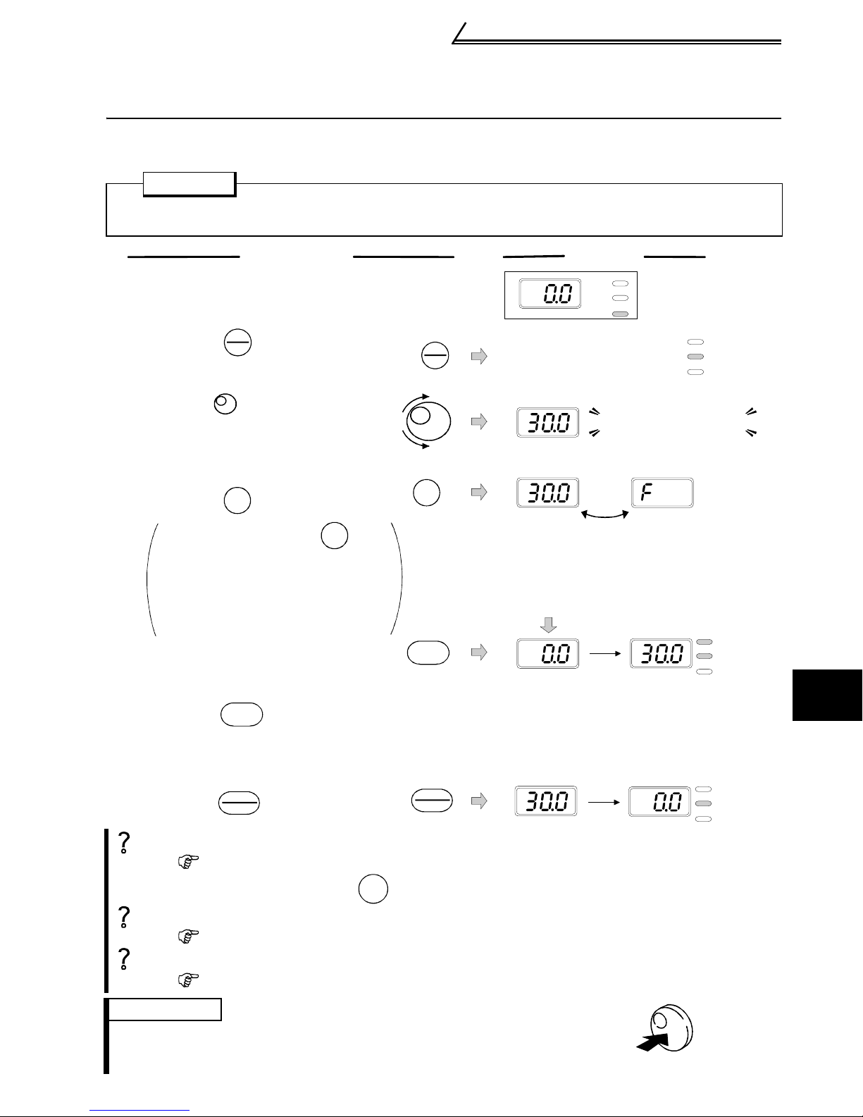
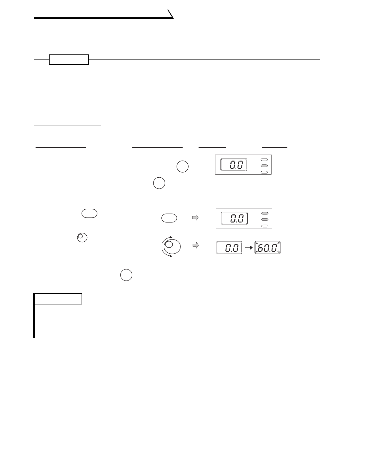
4.3.1 Setting the frequency to perform operation
(example: performing operation at 30Hz)
POINT
•Set "0" (setting dial frequency setting mode) in Pr. 53 "frequency setting
operation selection".
Operation
Screen at power-on
1.
The monitor display appears.
2.
Press the
to choose the PU
operation mode.
Turn the to show
3.
the frequency you want to set.
Flickers for about 5s.
While the value is flickering,
4.
press the to set the
frequency.
If you do not press the ,
the value flickers for about 5s and
the display then returns to 0.0
(monitor display). At this time,
return to "step 3" and set the
frequency again.
5.
After the value flickered for about
3s, the display returns to 0.0
(monitor display).
Press the to start operation.
To change the set frequency, perform
6.
the operation in above steps 3 and 4.
(Starting from the previously set frequency.)
Press the to stop.
7.
PU
EXT
SET
RUN
STOP
RESET
SET
PU
EXT
SET
RUN
STOP
RESET
Display
RUN
PU
EXT
RUN
PU indication is lit.
Flickers for about 5s.
Flicker...Frequency setting complete!!
3s later
PU
EXT
RUN
PU
EXT
RUN
PU
EXT
4
Operation cannot be performed at the set frequency ... Why?
Did you carry out step 4 within 5s after step 3?
(Did you press the within 5s after turning the setting dial?)
Setting of higher than 60Hz cannot be made ... Why?
Check to see if the Pr. 1 "maximum frequency" setting is 60Hz.
The frequency does not change by turning the setting dial ... Why?
Check to see if the operation mode selected is the external operation mode.
REMARKS
Pressing the setting dial shows the set frequency.
•The setting dial can also be used like a potentiometer to perform operation. (Refer to page 22.)
DRIVE THE MOTOR
SET
21
Operation by the start command from the operation panel
(PU operation mode)
4.3.2 Using the setting dial like a potentiometer to perform
operation
POINT
•Set "1" (extended function parameter valid) in Pr. 30 "extended function
display selection".
•Set "1" (setting dial potentiometer mode) in Pr. 53 "frequency setting
operation selection".
Operation example Changing the frequency from 0Hz to 60Hz during operation
Operation
Mode/monitor check.
1.
Choose monitor/frequency monitor.
The inverter must be in the
PU operation mode.
Pr. 30 must be set to "1".
Pr. 53 must be set to "1".
Press the to start
2.
RUN
the inverter.
Turn the clockwise
3.
(Press the .)
PU
EXT
( )
RUN
MODE
Display
RUN
PU
EXT
RUN
PU
EXT
until "60.0" appears.
The flickering frequency is
the set frequency.
You need not press the .
SET
Flickers for 3s.
REMARKS
•If flickering "60.0" turns to "0.0", the Pr. 53 "frequency setting operation selection" setting may
not be "1".
•Independently of whether the inverter is running or at a stop, the frequency can be set by
merely turning the dial.
22
Operation by the start command from the operation panel
(PU operation mode)
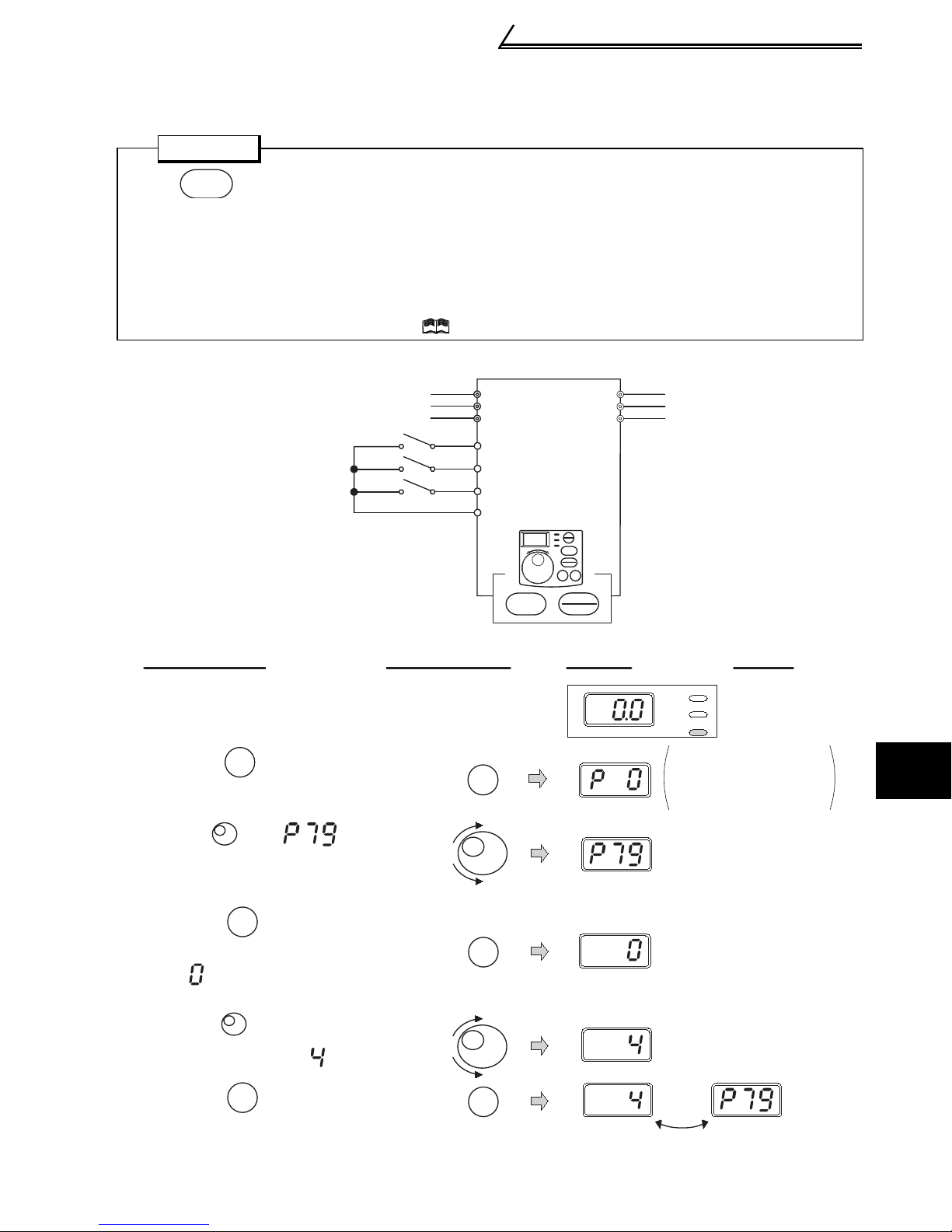
4.3.3 Use switchs to give a start command and a frequency
command (multi-speed setting)
POINT
•Use to give a start command.
RUN
•Pr. 79 "Operation mode selection" must be set to "4" (external/PU combined
operation mode 2)
•The factory setting of the terminal RH, RM, RL, are 60Hz, 30Hz, and 10Hz.
(Refer to page 44 to change frequency using Pr. 4, Pr. 5 and Pr. 6.)
•Operation at 15-speed can be performed by turning on two (or three) terminals simultaneously. (Refer to Instruction Manual (detailed).)
Inverter
Three-phase
AC power supply
High speed
Middle speed
Low speed
R
S
T
RH
RM
RL
SD
Operation
panel
㧗㧙
RUN
、
STOP
RESET
U
V
W
Motor
Operation
Screen at powering on
1.
The monitor display appears.
2.
Press to choose the
parameter setting mode.
Turn until (Pr.79)
3.
appears.
Press to read the currently
4.
set value.
" "(factory setting) appears.
Turn to change it to the
5.
setting value of " ".
Press to set.
6.
MODE
SET
SET
MODE
SET
SET
Display
RUN
PU
EXT
The parameter
number read
previously appears.
4
DRIVE THE MOTOR
Flicker
23
・・・
Parameter setting complete!!
 Loading...