

Mitsubishi FR-S520SE-0.1K, FR-S540E Series, FR-S520SE-0.4K, FR-S520SE Series, FR-S520SE-0.75K Instruction Manual
...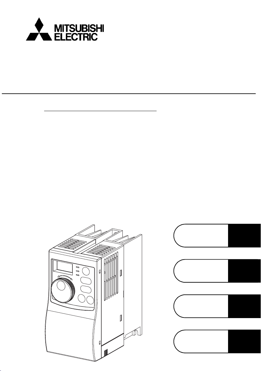
TRANSISTORIZED INVERTER
FR-S500
INSTRUCTION MANUAL (Detailed)
SIMPLE INVERTER
FR-S520E-0.1K to 3.7K (-C)
FR-S540E-0.4K to 3.7K
FR-S520SE-0.1K to 1.5K
FR-S510WE-0.1K to 0.75K
WIRING
FUNCTIONS
PROTECTIVE
FUNCTIONS
SPECIFICATIONS
Chapter 1
Chapter 2
Chapter 3
Chapter 4
Thank you for choosing this Mitsubishi Transistorized inverter.
This instruction manual (detailed) provides instructions for advanced use of the FRS500 series inverters.
Incorrect handling might cause an unexpected fault. Before using the inverter, always
read this instruction manual and the instruction manual (basic) [IB-0600151E] packed
with the product carefully to use the equipment to its optimum.
This section is specifically about safety matters
Do not attempt to install, operate, maintain or inspect the inverter until you have read
through this instruction manual (basic) and appended documents carefully and can
use the equipment correctly. Do not use the inverter until you have a full knowledge
of the equipment, safety information and instructions.
In this instruction manual (detailed), the safety instruction levels are classified into
"WARNING" and "CAUTION".
WARNING
CAUTION
Assumes that incorrect handling may cause hazardous
conditions, resulting in death or severe injury.
Assumes that incorrect handling may cause hazardous
conditions, resulting in medium or slight injury, or may cause
physical damage only.
Note that even the level may lead to a serious consequence
according to conditions. Please follow the instructions of both levels because they are
important to personnel safety.
CAUTION
1. Electric Shock Prevention
WARNING
z While power is on or when the inverter is running, do not open the front cover. You
may get an electric shock.
z Do not run the inverter with the front cover or wiring cover removed. Otherwise,
you may access the exposed high-voltage terminals or the charging part of the
circuitry and get an electric shock. Also, the inverter's ability to withstand
earthquakes will deteriorate.
z Even if power is off, do not remove the front cover except for wiring or periodic
inspection. You may access the charged inverter circuits and get an electric shock.
z Before starting wiring or inspection, check to make sure that the 3-digit LED inverter
monitor is off, wait for at least 10 minutes after the power supply has been switched
off, and check to make sure that there are no residual voltage using a tester or the
like.
z This inverter must be earthed (grounded). Earthing (grounding) must conform to
the requirements of national and local safety regulations and electrical codes.
(NEC section 250, IEC 536 class 1 and other applicable standards)
z Any person who is involved in the wiring or inspection of this equipment should be
fully competent to do the work.
z Always install the inverter before wiring. Otherwise, you may get an electric shock
or be injured.
z Perform setting dial and key operations with dry hands to prevent an electric
shock.
z Do not subject the cables to scratches, excessive stress, heavy loads or pinching.
Otherwise, you may get an electric shock.
z Do not change the cooling fan while power is on. It is dangerous to change the
cooling fan while power is on.
z When you have removed the front cover, do not touch the connector above the 3-
digit monitor LED display. Otherwise, you get an electrick shock.
A-1
2. Fire Prevention
CAUTION
z Install the inverter and brake resistor on an incombustible wall without holes, etc.
Installing the inverter and brake resistor directly on or near a combustible surface could
lead to a fire.
z If the inverter has become faulty, switch off the inverter power. A continuous flow of
large current could cause a fire.
z When using a brake resistor, make up a sequence that will turn off power when an
alarm signal is output. Otherwise, the brake resistor may excessively overheat due
to damage of the brake transistor and such, causing a fire.
z
Do not connect the resistor directly to the DC terminals P and N. This could cause a fire.
3. Injury Prevention
CAUTION
z Apply only the voltage specified in the instruction manual to each terminal to
prevent damage, etc.
z Always connect to the correct terminal to prevent damage, etc.
z Always make sure that polarity is correct to prevent damage, etc.
z While power is on or for some time after power-off, do not touch the inverter as it is
hot and you may get burnt.
4. Additional Instructions
Also note the following points to prevent an accidental failure, injury, electric shock,
etc.
(1) Transportation and installation
CAUTION
z When carrying products, use correct lifting gear to prevent injury.
z Do not stack the inverter boxes higher than the number recommended.
z Ensure that installation position and material can withstand the weight of the
inverter. Install according to the information in the instruction manual.
z Do not install or operate if the inverter is damaged or has parts missing.
z When carrying the inverter, do not hold it by the front cover or setting dial; it may
fall off or fail.
z Do not stand or rest heavy objects on the inverter.
z Check the inverter mounting orientation is correct.
z Prevent other conductive bodies as screws and metal fragments or other
flammable substance as oil from entering the inverter.
z As the inverter is a precision instrument, do not drop or subject it to impact.
z Use the inverter under the following environmental conditions: This could cause
the inverter damage.
Ambient
Temperature
Ambient humidity 90%RH maximum (non-condensing)
Storage
temperature
Atmosphere
Environment
Altitude/
vibration
*Temperatures applicable for a short time, e.g. in transit.
-10°C to +50°C (non-freezing)
(-10°C to +40°C for totally enclosed structure feature)
-20°C to +65°C *
Indoors (free from corrosive gas, flammable gas, oil mist,
dust and dirt)
Max.1000m above sea level 5.9m/s
2
or less
A-2

(2) Wiring
CAUTION
z Do not fit capacitive equipment such as power factor correction capacitor,
capacitor type filter (option FR-BIF(-H)) or surge suppressor to the output of the
inverter.
z The connection orientation of the output cables U, V, W to the motor will affect the
direction of rotation of the motor.
(3) Trial run
CAUTION
z Check all parameters, and ensure that the machine will not be damaged by a
sudden start-up.
z When the load GD
output current may vary when the output frequency is in the 20Hz to 30Hz range.
If this is a problem, set the Pr.72 "PWM frequency selection" to 6kHz or higher.
(When setting the PWM to a higher frequency, check for noise or leakage current
problem and take countermeasures against it.)
(4) Operation
2
is small (at the motor GD or smaller) for 400V from 1.5K to 3.7K, the
WARNING
z When you have chosen the retry function, stay away from the equipment as it will
restart suddenly after an alarm stop.
z Since the [STOP] key is valid only when functions are set (refer to page 115),
provide a circuit and switch separately to make an emergency stop (power off,
mechanical brake operation for emergency stop, etc).
z Make sure that the start signal is off before resetting the inverter alarm. A failure to
do so may restart the motor suddenly.
z The load used should be a three-phase induction motor only. Connection of any
other electrical equipment to the inverter output may damage the equipment.
z Do not modify the equipment.
z Do not perform parts removal which is not instructed in this manual. Doing so may
lead to fault or damage of the inverter.
A-3
CAUTION
z The electronic thermal relay function does not guarantee protection of the motor
from overheating.
z Do not use a magnetic contactor on the inverter input for frequent starting/stopping
of the inverter.
z Use a noise filter to reduce the effect of electromagnetic interference. Otherwise
nearby electronic equipment may be affected.
z Take measures to suppress harmonics. Otherwise power supply harmonics from
the inverter may heat/damage the power capacitor and generator.
z When a 400V class motor is inverter-driven, please use an insulation-enhanced
motor or measures taken to suppress surge voltages. Surge voltages attributable to
the wiring constants may occur at the motor terminals, deteriorating the insulation of
the motor.
z When parameter clear or all clear is performed, reset the required parameters
before starting operations. Each parameter returns to the factory setting.
z The inverter can be easily set for high-speed operation. Before changing its
setting, fully examine the performances of the motor and machine.
z In addition to the inverter's holding function, install a holding device to ensure safety.
z Before running an inverter which had been stored for a long period, always
perform inspection and test operation.
(5) Emergency stop
CAUTION
z Provide a safety backup such as an emergency brake which will prevent the
machine and equipment from hazardous conditions if the inverter fails.
z When the breaker on the inverter primary side trips, check for the wiring fault (short
circuit), damage to internal parts of the inverter, etc. Identify the cause of the trip,
then remove the cause and power on the breaker.
z When any protective function is activated, take the appropriate corrective action,
then reset the inverter, and resume operation.
(6) Maintenance, inspection and parts replacement
CAUTION
z Do not carry out a megger (insulation resistance) test on the control circuit of the
inverter.
(7) Disposing of the inverter
CAUTION
z Treat as industrial waste.
(8) General instructions
Many of the diagrams and drawings in this instruction manual (detailed) show the inverter
without a cover, or partially open. Never operate the inverter in this manner. Always replace
the cover and follow this instruction manual (detailed) when operating the inverter.
A-4

CONTENTS
1. WIRING 1
1.1 Standard connection diagram and terminal specifications ..2
1.1.1 Standard connection diagram ....................................................................... 2
1.1.2 Explanation of main circuit terminals............................................................. 3
1.2 Main circuit terminals ...............................................................6
1.2.1 Terminal block layout ....................................................................................6
1.2.2 Cables, wiring length, and crimping terminals............................................... 8
1.2.3 Wiring instructions .........................................................................................9
1.2.4 Selection of peripheral devices ...................................................................10
1.2.5 Leakage current and installation of earth (ground) leakage circuit breaker 12
1.2.6 Power-off and magnetic contactor (MC)...................................................... 16
1.2.7 Regarding the installation of the reactor......................................................17
1.2.8 Regarding noise and the installation of a noise filter...................................18
1.2.9 Earthing (Grounding) precautions ............................................................... 19
1.2.10 Power supply harmonics ............................................................................. 20
1.2.11 Harmonic suppression guideline ................................................................. 21
1.2.12 Inverter-driven 400V class motor ................................................................ 25
1.3 How to use the control circuit terminals ...............................26
1.3.1 Terminal block layout ..................................................................................26
1.3.2 Wiring instructions .......................................................................................26
1.3.3 Changing the control logic........................................................................... 27
CONTENTS
1.4 Input terminals.........................................................................29
1.4.1 Run (start) and stop (STF, STR, STOP) .....................................................29
1.4.2 Connection of frequency setting potentiometer and
output frequency meter (10, 2, 5, 4, AU)..................................................... 32
1.4.3 External frequency selection (REX, RH, RM, RL)....................................... 33
1.4.4 Indicator connection and adjustment (FM)..................................................35
1.4.5 Control circuit common terminals (SD, 5, SE).............................................37
1.4.6 Signal inputs by contactless switches ......................................................... 37
1.5 How to use the input signals
(assigned terminals RL, RM, RH, STR)..................................38
1.5.1 Multi-speed setting (RL, RM, RH, REX signals):
Pr. 60 to Pr. 63 setting "0, 1, 2, 8"
Remote setting (RL, RM, RH signals):
Pr. 60 to Pr. 63 setting "0, 1, 2" ................................................................... 38
1.5.2 Second function selection (RT signal): Pr. 60 to Pr. 63 setting "3" ............. 38
I

1.5.3 Current input selection "AU signal": Pr. 60 to Pr. 63 setting "4".................. 38
1.5.4 Start self-holding selection (STOP signal): Pr. 60 to Pr. 63 setting "5"....... 39
1.5.5 Output shut-off (MRS signal): Pr. 60 to Pr. 63 setting "6" ........................... 39
1.5.6 External thermal relay input: Pr. 60 to Pr. 63 setting "7" ............................. 40
1.5.7 Jog operation (JOG signal): Pr. 60 to Pr. 63 setting "9".............................. 40
1.5.8 Reset signal: Pr. 60 to Pr. 63 setting "10"................................................... 41
1.5.9 PID control valid terminal: Pr. 60 to Pr. 63 setting "14"............................... 42
1.5.10 PU operation/external operation switchover: Pr. 60 to Pr. 63 setting "16" .. 42
1.6 Connection to the stand-alone option .................................. 43
1.6.1 Connection of the dedicated external brake resistor (option) (FR-S520E-0.4K
to 3.7K only)................................................................................................ 43
1.6.2 Connection of the brake unit (BU type)....................................................... 44
1.6.3 Connection of the high power factor converter (FR-HC)............................. 45
1.6.4 Connection of the power regeneration common converter (FR-CV)........... 46
1.7 Handling of the RS-485 connector ........................................ 47
1.7.1 Connection of the parameter unit (FR-PU04) ............................................. 47
1.7.2 Wiring of RS-485 communication ............................................................... 48
1.8 Design information ................................................................. 51
1.9 Failsafe of the system which uses the inverter....................52
2. FUNCTIONS 55
2.1 Function (Parameter) list........................................................56
2.2 List of parameters classified by purpose of use..................69
2.3 Explanation of functions (parameters) ................................. 71
2.3.1 Torque boost (Pr. 0 , Pr. 46 ) ...................................................................... 71
2.3.2 Maximum and minimum frequency (Pr. 1 , Pr. 2 ) ...................................... 72
2.3.3 Base frequency, base frequency voltage (Pr.3 , Pr.19 , Pr.47 ).................. 73
2.3.4 Multi-speed operation (Pr. 4, Pr. 5, Pr. 6, Pr. 24 to Pr. 27, Pr. 80 to Pr. 87)75
2.3.5 Acceleration/deceleration time (Pr. 7 , Pr. 8 , Pr. 20 , Pr. 44 , Pr. 45 ) ....... 76
2.3.6 Selection and protection of a motor (Pr. 9 , Pr. 71 , H7 ) ............................ 78
2.3.7 DC injection brake (Pr. 10 , Pr. 11 , Pr. 12 ) ............................................... 80
2.3.8 Starting frequency (Pr. 13 )......................................................................... 81
2.3.9 Load pattern selection (Pr. 14 )................................................................... 82
2.3.10 Jog operation (Pr.15 , Pr.16 )...................................................................... 83
2.3.11 RUN key rotation direction selection (Pr.17 ).............................................. 83
2.3.12 Stall prevention function and current limit function (Pr. 21 ) ....................... 84
2.3.13 Stall prevention (Pr. 22 , Pr. 23 , Pr. 28 ) .................................................... 86
II

2.3.14 Acceleration/deceleration pattern (Pr. 29 ).................................................. 88
2.3.15 Extended function display selection (Pr. 30 ) .............................................. 89
2.3.16 Frequency jump (Pr. 31 to Pr. 36 )............................................................. 89
2.3.17 Speed display (Pr. 37 )................................................................................ 90
2.3.18 Biases and gains of the frequency setting voltage (current)
(Pr. 38 , Pr. 39 , C2 to C7 )......................................................................... 91
2.3.19 Start-time earth (ground) fault detection selection (Pr. 40 ) ........................ 95
2.4 Output terminal function ........................................................95
2.4.1 Up-to-frequency sensitivity (Pr. 41 )............................................................ 95
2.4.2 Output frequency detection (Pr. 42 , Pr. 43 )...............................................96
2.5 Current detection function .....................................................97
2.5.1 Output current detection functions (Pr. 48 , Pr. 49 )....................................97
2.5.2 Zero current detection (Pr. 50 , Pr. 51 ).......................................................98
2.6 Display function ......................................................................99
2.6.1 Monitor display (Pr. 52 , Pr. 54 )..................................................................99
2.6.2 Setting dial function selection (Pr. 53 )...................................................... 100
2.6.3 Monitoring reference (Pr. 55 , Pr. 56 )....................................................... 101
2.7 Restart operation function ...................................................101
2.7.1 Restart setting (Pr. 57 , Pr. 58 , H6 ) ......................................................... 101
2.8 Additional function................................................................104
2.8.1 Remote setting function selection (Pr. 59 ) ...............................................104
CONTENTS
2.9 Terminal function selection..................................................108
2.9.1 Input terminal function selection (Pr. 60 , Pr. 61 , Pr. 62 , Pr. 63 )............ 108
2.9.2 Output terminal function selection (Pr. 64 , Pr. 65 ) .................................. 110
2.10 Operation selection function................................................111
2.10.1 Retry function (Pr. 66 , Pr. 67 , Pr. 68 , Pr. 69 ) ........................................111
2.10.2 PWM carrier frequency and long wiring mode (Pr. 70 , Pr. 72 )................113
2.10.3 Voltage input selection (Pr. 73 ) ................................................................ 114
2.10.4 Input filter time constant (Pr. 74 ) .............................................................. 115
2.10.5 Reset selection/PU stop selection (Pr. 75 )............................................... 115
2.10.6 Cooling fan operation selection (Pr. 76 )................................................... 117
2.10.7 Parameter write disable selection (Pr. 77 ) ............................................... 118
2.10.8 Reverse rotation prevention selection (Pr. 78 )......................................... 119
2.10.9 Operation mode selection (Pr. 79 ) ........................................................... 119
2.10.10PID control (Pr. 88 to Pr. 94 )................................................................... 123
2.11 Auxiliary function ..................................................................131
2.11.1 Slip compensation (Pr. 95 , Pr. 96 , Pr. 97 )..............................................131
III

2.11.2 Automatic torque boost selection (Pr. 98 )................................................ 132
2.11.3 Motor primary resistance (Pr. 99 ) ............................................................ 133
2.12 Maintenance function ........................................................... 133
2.12.1 Maintenance output function (H1, H2 ) ..................................................... 133
2.12.2 Current average value monitor signal (H3, H4, H5).......... ......... 134
2.13 Brake parameters (FR-S520E-0.4K to 3.7K only) ............... 137
2.13.1 Regenerative braking operation (b1 , b2 ) ................................................ 137
2.14 Calibration parameters ......................................................... 138
2.14.1 Meter (frequency meter) calibration (C1 )................................................. 138
2.15 Clear parameters................................................................... 141
2.15.1 Parameter clear (CLr ) .............................................................................. 141
2.15.2 Alarm history clear (ECL )......................................................................... 141
2.16 Communication parameters................................................. 142
2.16.1 Communication settings (n1 to n7 , n11 ) ................................................ 144
2.16.2 Operation and speed command source (n8 , n9 ) .................................... 160
2.16.3 Link startup mode selection (n10 )............................................................ 161
2.16.4 EEPROM write selection (n12 ) ................................................................ 163
2.17 Parameter unit (FR-PU04) setting........................................ 164
2.17.1 PU display language selection (n13 ) ....................................................... 164
2.17.2 PU buzzer control (n14 )........................................................................... 164
2.17.3 PU contrast adjustment (n15 ) .................................................................. 165
2.17.4 PU main display screen data selection (n16 )........................................... 165
2.17.5 Disconnected PU detection/PU setting lock selection (n17 ) .................... 166
3. PROTECTIVE FUNCTIONS 169
3.1 Errors (Alarms)...................................................................... 170
3.1.1 Error (alarm) definitions ............................................................................ 171
3.1.2 To know the operating status at the occurrence of alarm
(only when FR-PU04 is used)................................................................... 179
3.1.3 Correspondence between digital and actual characters ........................... 179
3.1.4 Resetting the inverter................................................................................ 179
3.1.5 Checking of the alarm history ................................................................... 180
3.2 Troubleshooting.................................................................... 181
3.2.1 Motor remains stopped ............................................................................. 181
3.2.2 Motor rotates in opposite direction............................................................ 182
3.2.3 Speed greatly differs from the setting ....................................................... 182
IV

3.2.4 Acceleration/deceleration is not smooth....................................................182
3.2.5 Motor current is large ................................................................................ 182
3.2.6 Speed does not increase...........................................................................182
3.2.7 Speed varies during operation .................................................................. 182
3.2.8 Operation mode is not changed properly ..................................................183
3.2.9 Operation panel display is not operating...................................................183
3.2.10 Parameter write cannot be performed....................................................... 183
3.2.11 Motor produces annoying sound............................................................... 183
3.3 Precautions for maintenance and inspection.....................184
3.3.1 Precautions for maintenance and inspection ............................................184
3.3.2 Inspection item .......................................................................................... 184
3.3.3 Periodic inspection ....................................................................................184
3.3.4 Insulation resistance test using megger....................................................185
3.3.5 Pressure test ............................................................................................. 185
3.3.6 Daily and periodic inspection..................................................................... 186
3.3.7 Checking the inverter and converter module.............................................188
3.3.8 Replacement of parts................................................................................189
3.3.9 Measurement of main circuit voltages, currents and powers .................... 192
4. SPECIFICATIONS 195
4.1 Specification list ....................................................................196
4.1.1 Ratings ...................................................................................................... 196
4.1.2 Common specifications............................................................................. 200
CONTENTS
4.2 Outline dimension drawings ................................................202
APPENDIX 205
APPENDIX 1 Parameter instruction code list ...............................206
V

1. WIRING
This chapter explains the basic "wiring" for use of this product. Always
read the instructions before use.
For description of "installation", refer to the instruction manual (basic).
1.1 Standard connection diagram and terminal
specifications .....................................................
1.2 Main circuit terminals ........................................ 6
1.3 How to use the control circuit terminals.......... 26
1.4 Input terminals.................................................... 29
1.5 How to use the input signals (assigned
terminals RL, RM, RH, STR) ..............................
1.6 Connection to the stand-alone option.............. 43
1.7 Handling of the RS-485 connector...................... 47
1.8 Design information............................................. 51
2
38
<Abbreviations>
•PU
Operation panel and parameter unit (FR-PU04)
•Inverter
Mitsubishi transistorized inverter FR-S500 series
•FR-S500
Mitsubishi transistorized inverter FR-S500 series
•Pr.
Parameter number
1
Chapter 1
Chapter 2
Chapter 3
Chapter 4
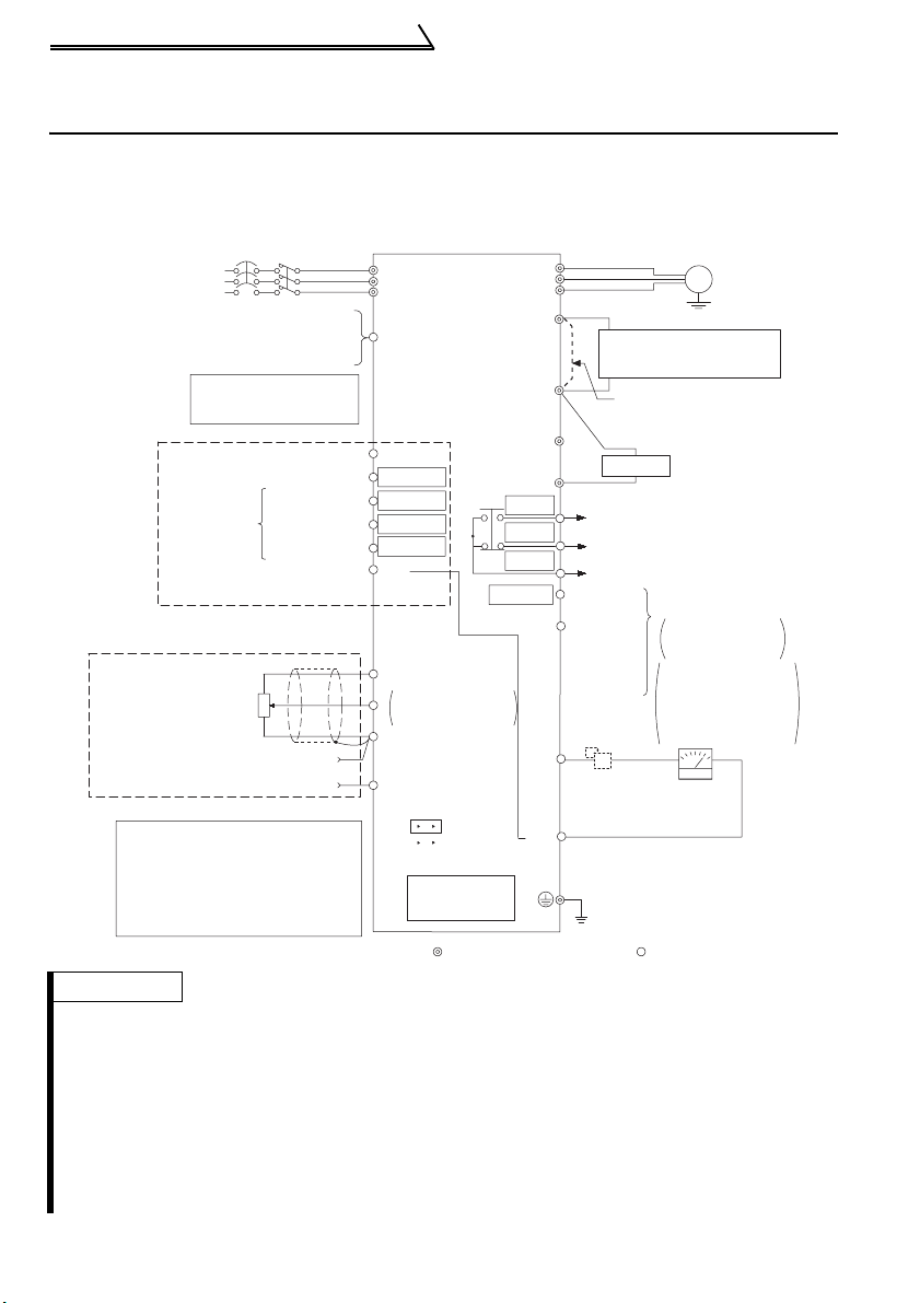
Standard connection diagram and terminal specifications
1.1 Standard connection diagram and terminal specifications
1.1.1 Standard connection diagram
z Three-phase 200V power input
z Three-phase 400V power input
MCCB
Three-phase AC
power supply
External transistor common
24VDC power supply
Contact input common (source)
Take care not to short
terminals PC-SD.
Control input
signals
(No voltage
input allowed)
Frequency setting signals (Analog)
Frequency setting
potentiometer
1/2W1kW
Forward rotation start
Reverse rotation start
Multi-speed
selection
Contact input common
*5
MC
High speed
Middle speed
Low speed
3
2
1
Current input(-)
4 to 20mADC(+)
When using the current input as
the frequency setting signal, set
"4" in any of Pr. 60 to Pr. 63 (input
terminal function selection), assign
AU (current input selection) to any
of terminals RH, RM, RL and STR
and turn on the AU signal.
REMARKS
*1. The N/- terminal is not provided for the FR-S520E-0.1K to 0.75K.
*2. The PR terminal is provided for the FR-S520E-0.4K to 3.7K.
*3. Not needed when the setting dial is used for calibration.
Used when calibration must be made near the frequency meter for such a reason as a remote frequency meter.
However, the frequency meter needle may not deflect to full-scale if the calibration resistor is connected.
In this case, use this resistor and setting dial together.
*4. You can switch the position of sink and source logic. (Refer to page 27.)
*5. When the setting potentiometer is used frequently, use a 2W1kΩ potentiometer.
*6. The terminal functions change with input terminal function selection (Pr. 60 to Pr. 63). (Refer to page 108.)
(RES, RL, RM, RH, RT, AU, STOP, MRS, OH, REX, JOG, X14, X16, (STR) signal selection)
*7. The terminal function changes according to the setting of output terminal function selection (Pr. 64, Pr. 65).
(Refer to page 110.) (RUN, SU, OL, FU, RY, Y12, Y13, FDN, FUP, RL, Y93, Y95, LF, ABC signal selection)
Inverter
R/L1
S/L2
T/L3
PC
STF
STR
*6
*6
RH
*6
RM
RL
*6
SD
10
(+5V)
0 to 5VDC
2
0 to 10VDC
5
(Common)
4
(4 to 20mADC)
SINK
SOURCE
RS-485
Connector
*7
Selected
*4
*1
*2
*7
*7
*7
RUN
W
P1
P/+
N/-
PR
SE
FM
SD
U
V
A
B
C
Motor
DC reactor
(FR-HEL/BEL: Option)
Jumper:
jumper when DC reactor
is connected.
Alarm output
Running
Open
collector
output
common
Calibration
resistor
Remove this
Brake resister
R
Operation status
output
Open collector
outputs
Indicator
1mA full-scale
Analog meter
(Digital indicator)
(+)
*3
Earth (Ground)
Control circuit terminalMain circuit terminal
IM
Earth
(Ground)
(-)
2
Standard connection diagram and terminal specifications
CAUTION
To prevent a malfunction due to noise, keep the signal cables more than 10cm away
from the power cables.
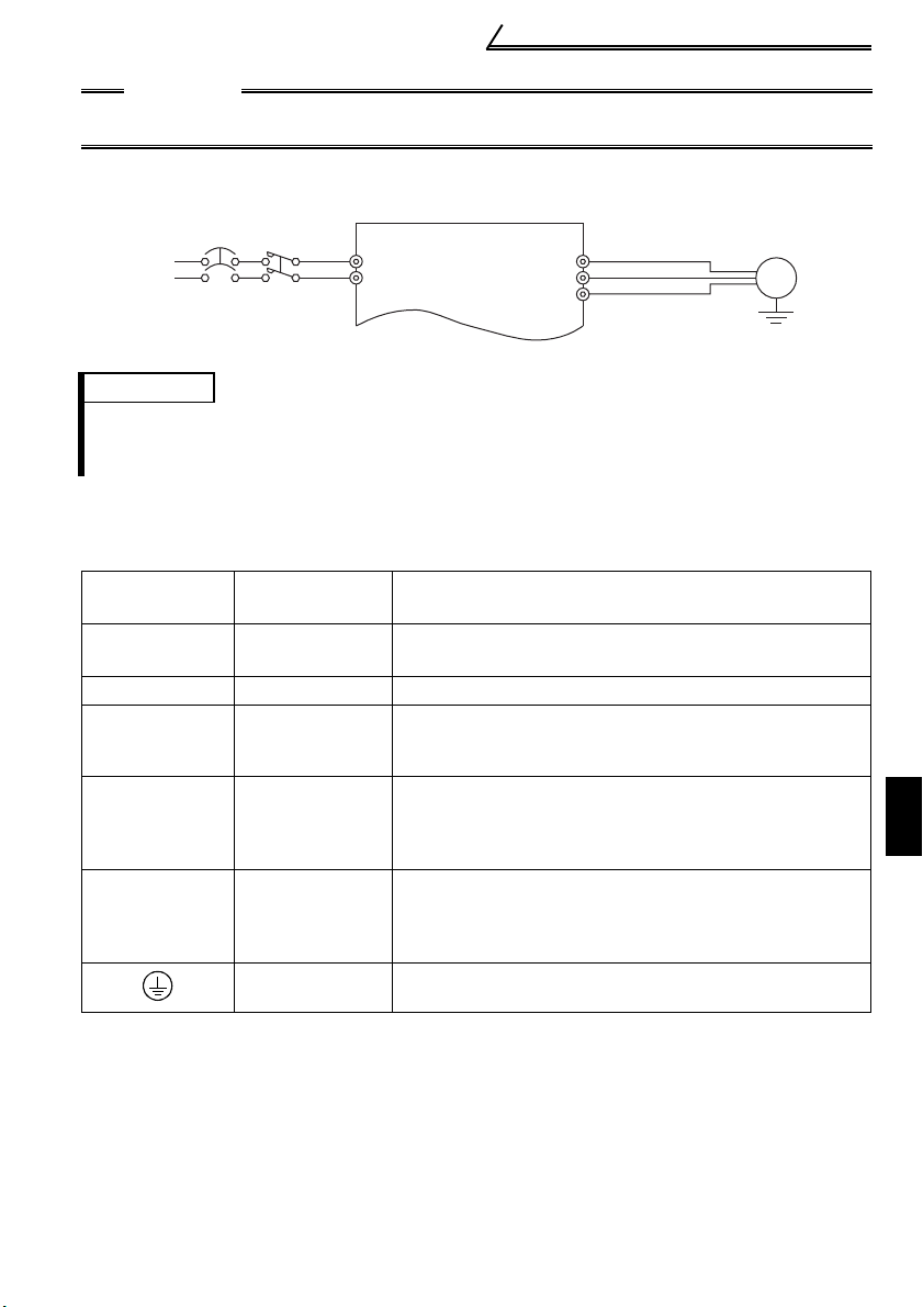
z Single-phase 200V power input
z Single-phase 100V power input
Power
MCCB
supply
MC
R/L1
S/L
U
2
V
W
Motor
IM
Earth (Ground)
REMARKS
•To ensure safety, connect the power input to the inverter via a magnetic contactor and earth leakage
circuit breaker or moulded case circuit breaker, and use the magnetic contactor to switch power on-off.
•The output is three-phase 200V.
1.1.2 Explanation of main circuit terminals
(1) Main circuit
Term inal
Symbol
R/L1, S/L2,
T/L3 (*1)
U, V, W Inverter output
P/+, PR (*2)
P/+, N/−
P/+, P1
*1. When using single-phase power input, terminals are R/L1 and S/L2.
*2. The PR terminal is provided for the FR-S520E-0.4K to 3.7K.
Terminal Name Description
AC power input
Brake resistor
connection
Brake unit
connection
DC reactor
connection
Earth (ground)
Connect to the commercial power supply.
Connect a three-phase squirrel-cage motor.
Connect the optional brake resistor (MRS/MYS type, FRABR) (The brake resistor can be connected to the FRS520E-0.4K to 3.7K only.)
Connect the brake unit (BU), power regeneration
common converter (FR-CV) or high power factor
converter (FR-HC). (The N/- terminal is not provided for
the FR-S520E-0.1K to 0.75K.)
Remove the jumper across terminals P - P1 and connect
the optional DC reactor (FR-HEL(-H)/FR-BEL(-H)).
(The single-phase 100V power input model cannot be
connected.)
For earthing (grounding) the inverter chassis. Must be
earthed (grounded).
1
WIRING
3
Standard connection diagram and terminal specifications
(2) Control circuit
Symbol Terminal Name Definition
Turn on the STF signal to start
forward rotation and turn it off
to stop.
Turn on the STR signal to start
reverse rotation and turn it off
to stop.
Turn on the RH, RM and RL signals in
appropriate combinations to select
multiple speeds.
The priorities of the speed commands
are in order of jog, multi-speed setting
(RH, RM, RL, REX) and AU.
Common terminal for contact input terminal (sink logic) and
terminal FM.
When connecting the transistor output (open collector
output), such as a programmable controller (PLC), when
source logic is selected, connect the external power supply
common for transistor output to this terminal to prevent a
malfunction caused by undesirable currents.
Common output terminal for 24VDC 0.1A power supply (PC
terminal)
Isolated from terminals 5 and SE.
When connecting the transistor output (open collector
output), such as a programmable controller (PLC), when sink
logic is selected, connect the external power supply common
for transistor output to this terminal to prevent a malfunction
caused by undesirable currents.
Common terminal for contact input terminal (source logic)
Can be used as 24VDC 0.1A power supply.
5VDC, Permissible load current 10mA.
Input signals
STF
STR
RH
Contact input
RM
RL
SD
(*1, 6)
PC
(*1)
10
Forward rotation
start
Reverse rotation
start
Multi-speed
selection
Contact input
common (sink)
(initial setting)
External
transistor
common (source)
24VDC power
supply common
External
transistor
common (sink)
(initial setting)
Contact input
common (source)
24VDC power
supply
Frequency setting
power supply
When the STF and STR
signals are turned on
simultaneously, the stop
command is given.
The terminal
functions change
with input terminal
function selection
(Pr. 60 to Pr. 63).
(*3)
4
Standard connection diagram and terminal specifications
Symbol Terminal Name Definition
Frequency setting
2
(voltage signal)
Frequency setting
4
(current signal)
Input signals
Frequency setting
Frequency setting
5
input common
A
BCAlarm output
Inverter
RUN
running
Open collector
Open collector
SE
common
Output signals
FM For meter
Indicator
Inputting 0 to 5VDC (or 0 to 10V) provides the maximum output
frequency at 5V (10V) and makes input and output proportional.
Switch between 5V and 10V using Pr. 73 "0-5V, 0-10V selection".
Input resistance 10kΩ. Maximum permissible input voltage 20V
Input 4 to 20mADC. It is factory set at 0Hz for 4mA and at
60Hz for 20mA.
Maximum permissible input current 30mA. Input resistance
approximately 250Ω.
Turn ON signal AU for current input.
Turning the AU signal on makes voltage input invalid. Use
any of Pr. 60 to Pr. 63 (input terminal function selection) to set
the AU signal.
Frequency setting signal (terminal 2, 4) common terminal.
(*6)
1 changeover contact output indicates
that the inverter protective function has
activated and the output stopped.
230VAC 0.3A, 30VDC 0.3A. Alarm:
discontinuity across B-C (continuity
across A-C), Normal: continuity across BC (discontinuity across A-C).(*5)
Switched low when the inverter output
frequency is equal to or higher than the
starting frequency (factory set to 0.5Hz
variable). Switched high during stop or DC
injection brake operation. (*2) Permissible
load 24VDC 0.1A (a voltage drop is 3.4V
maximum when the signal is on)
Common terminal for inverter running terminal RUN.
The output signal across terminals FM-SD is factory set to
about 1mA at 60Hz and is proportional to the corresponding
output frequency. Since output voltage is pulse waveform, a
digital meter can be connected.
Frequency permissible load current 1mA
Pulse specification 1440 pulses/s at 60Hz
The function of the
terminals changes
according to the
output terminal
function selection
(Pr. 64, Pr. 65).
(*4)
(*6)
1
Using the parameter unit connection cable (FR-CB201 to
205), the parameter unit (FR-PU04) can be connected.
Communication operation can be performed using RS-485.
For details of RS-485 communication, refer to page 48.
——
RS-485
connector
Communication
*1. Do not connect terminals SD and PC each other or to the earth (ground).
For sink logic (factory setting), terminal SD acts as the common terminal of contact input. For
source logic, terminal PC acts as the common terminal of contact input. (Refer to page 27 for
switching method.)
*2. Low indicates that the open collector output transistor is on (conducts). High indicates that the
transistor is off (does not conduct).
*3. RL, RM, RH, RT, AU, STOP, MRS, OH, REX, JOG, RES, X14, X16, (STR) signal selection
(Refer to page 108.)
*4. RUN, SU, OL, FU, RY, Y12, Y13, FDN, FUP, RL, Y93, Y95, LF, ABC signal selection (Refer to
page 110.)
*5. To be compliant with the European Directive (Low Voltage Directive), the operating capacity of
relay outputs (A, B, C) should be 30VDC 0.3A.
*6.
Terminals SD, SE and 5 are isolated from each other. Do not earth (ground).
5
WIRING
Main circuit terminals
r
r
1.2 Main circuit terminals
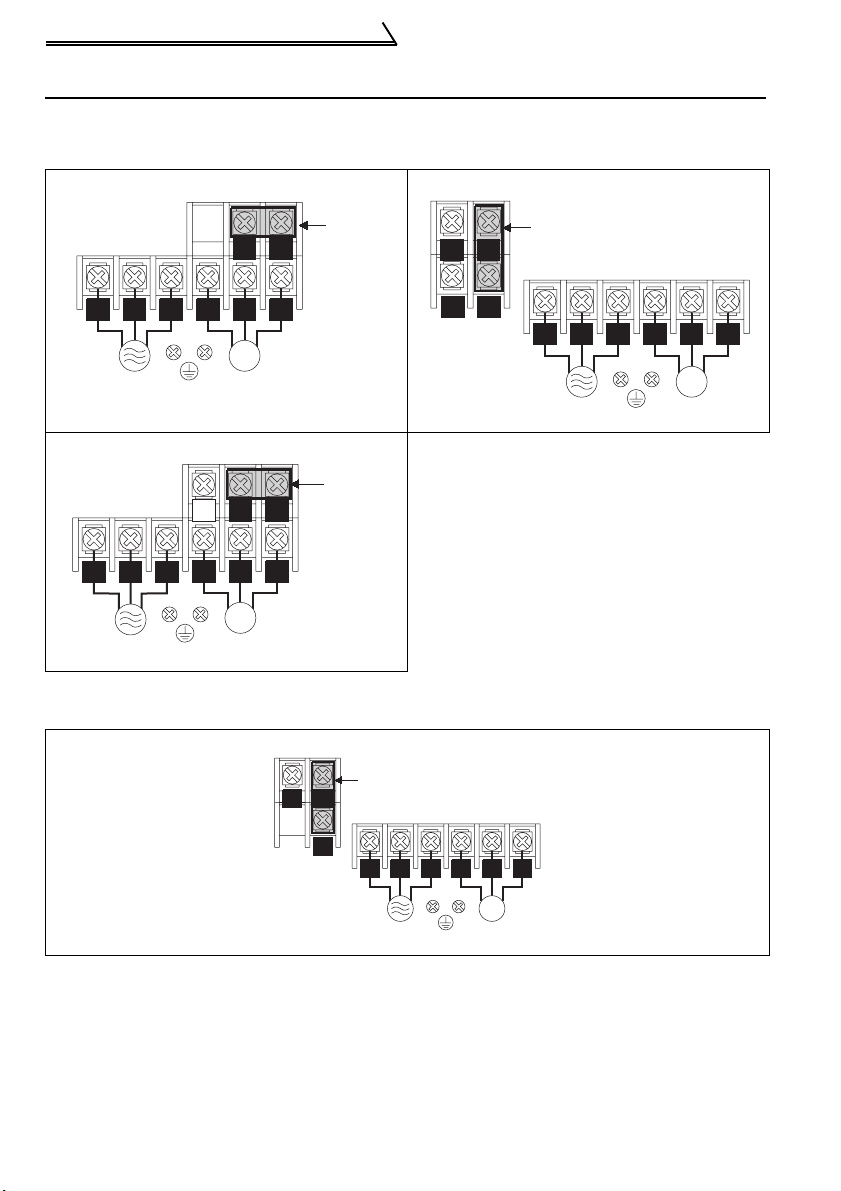
1.2.1 Terminal block layout
1) Three-phase 200V power input
• FR-S520E-0.1K, 0.2K (-C) • FR-S520E-1.5K, 2.2K, 3.7K (-C)
Jumpe
P/+
P1
R/L1 S/L2 T/L3
Power supply
U V W
IM
Motor
• FR-S520E-0.4K, 0.75K (-C)
Jumpe
P1
IM
Motor
P/+
R/L1 S/L2
T/L3
Power supply
PR
U V W
2) Three-phase 400V power input
• FR-S540E-0.4K, 0.75K, 1.5K, 2.2K, 3.7K (-C)
Jumper
P/+
N/-
N/-
PR
P/+
P1
Jumper
R/L1 S/L2 T/L3
Power supply
U V W
IM
Motor
P1
Power supply
R/L1 S/L2 T/L3
6
U V W
IM
Motor
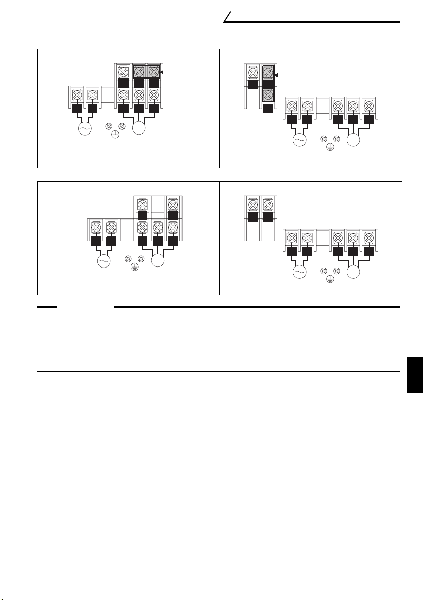
3) Single-phase 200V power input
r
• FR-S520SE-0.1K, 0.2K, 0.4K, 0.75K • FR-S520SE-1.5K
N/-
P1
P/+
N/-
Jumpe
Jumper
P/+
Main circuit terminals
R/L1 S/L2
Power supply
U V W
IM
Motor
P1
R/L1 S/L2
Power supply
U V W
IM
Motor
4) Single-phase 100V power input
• FR-S510WE-0.1K, 0.2K, 0.4K • FR-S510WE-0.75K
R/L1 S/L2
Power supply
P/+N/-
U V W
IM
Motor
N/-
P/+
R/L1 S/L2
Power supply
U V W
IM
Motor
CAUTION
•Make sure the power cables are connected to the R/L1, S/L2, T/L3 of the inverter.
Never connect the power cable to the U, V, W of the inverter. Doing so will damage
the inverter. (Phase need not be matched)
•Connect the motor to U, V, W. At this time, turning on the forward rotation switch
(signal) rotates the motor in the counterclockwise direction when viewed from the
motor shaft.
1
WIRING
7
Main circuit terminals
1.2.2 Cables, wiring length, and crimping terminals
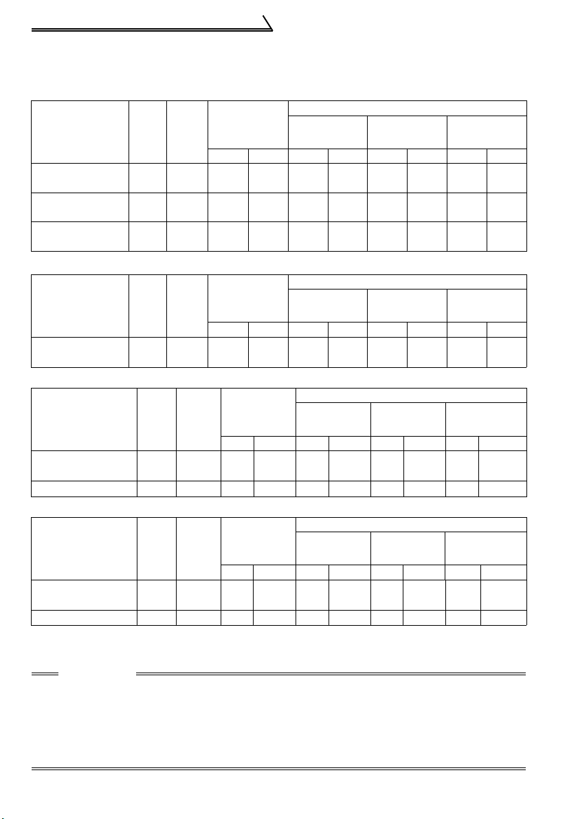
The following table indicates a selection example for the wiring length of 20m.
1) Three-phase 200V power input
2
)
2
)
Cable Size
AWG
R, S, T
U, V, W
Cable Size
AWG
Cable
AWG
Cable Size
AWG
PVC cable
2
(mm
R, S, T
U, V, W
PVC cable
2
(mm
PVC Cable
2
(mm
PVC cable
(mm2)
)
)
)
Ter-
Applied Inverter
FR-S520E-0.1K
to 0.75K (-C)
FR-S520E-
1.5K, 2.2K (-C)
FR-S520E-3.7K
(-C)
Tight-
minal
ening
Screw
Torque
size
N
M3.5 1.2 2-3.5 2-3.5 2 2 14 14 2.5 2.5
M4 1.5 2-4 2-4 2 2 14 14 2.5 2.5
M4 1.5 5.5-4 5.5-4 3.5 3.5 12 12 4 2.5
⋅
m
R, S, T U, V, W
Crimping
Ter minal
HIV cable
(mm2)
R, S, T
U, V, W
2) Three-phase 400V power input
Ter-
Applied Inverter
FR-S540E-0.4K
to 3.7K
Tight-
minal
ening
Screw
Torque
size
N
M4 1.5 2-4 2-4 2 2 14 14 2.5 2.5
Crimping
Ter minal
⋅
m
R, S, T U, V, W R, S, T U, V, W R, S, T U, V, W R, S, T U, V, W
HIV cable
(mm2)
3) Single-phase 200V power input
Applied Inverter
FR-S520SE-0.1K
to 0.75K
FR-S520SE-
1.5K
Termi-
Screw
Tight-
nal
ening
Tor qu e
size
M3.5 1.2 2-3.5 2-3.5 2 2 14 14 2.5 2.5
N
M4 1.5 2-4 2-4 2 2 14 14 2.5 2.5
Crimping
Term inal
⋅
m
R, S U, V, W R, S U, V, W R, S U, V, W R, S U, V, W
HIV cable
(mm
4) Single-phase 100V power input
Applied Inverter
FR-S510WE-
0.1K
to 0.4K
FR-S510WE-0.75K
Termi-
Screw
Tight-
nal
ening
Tor qu e
size
M3.5 1.2 2-3.5 2-3.5 2 2 14 14 2.5 2.5
N
M4 1.5 5.5-4 2-4 3.5 2 12 14 4 2.5
Crimping
Terminal
⋅
m
R, S U, V, W R, S U, V, W R, S U, V, W R, S U, V, W
HIV cable
(mm
z Wiring length
100m maximum. (50m maximum for the FR-S540E-0.4K.)
CAUTION
•When the wiring length of the 0.1K and 0.2K of the three-phase 200V, singlephase 200V, and single-phase 100V class and the 0.4K and 0.75K of the threephase 400V class is 30m or more, set the carrier frequency to 1kHz.
•When automatic torque boost is selected in Pr. 98 "automatic torque boost
selection (motor capacity)", the wiring length should be 30m maximum. (Refer
to page 132.)
8

Main circuit terminals
1.2.3 Wiring instructions
1) Use crimping terminals with insulation sleeve to wire the power supply and motor.
2) Application of power to the output terminals (U, V, W) of the inverter will damage the
inverter. Never perform such wiring.
3) After wiring, wire offcuts must not be left in the inverter.
Wire offcuts can cause an alarm, failure or malfunction. Always keep the inverter
clean.
When drilling mounting holes in an enclosure etc., take care not to allow chips and
other foreign matter to enter the inverter.
4) Use cables of the recommended size to make a voltage drop 2% maximum.
If the wiring distance is long between the inverter and motor, a main circuit cable
voltage drop will cause the motor torque to decrease especially at the output of a
low frequency.
5) For long distance wiring, the fast-response current limit function may be reduced or
the devices connected to the secondary side may malfunction or become faulty
under the influence of a charging current due to the stray capacity of wiring.
Therefore, note the maximum overall wiring length.
6) Electromagnetic wave interference
The input/output (main circuit) of the inverter includes high frequency components,
which may interfere with the communication devices (such as AM radios) used near
the inverter. In this case, install a FR-BIF(-H) optional capacitor type filter (for use
on the input side only) or FR-BSF01 or FR-BLF common mode filter to minimize
interference.
7) Do not install a power capacitor, surge suppressor or capacitor type filter (FR-BIF(H) option) on the output side of the inverter.
This will cause the inverter to trip or the capacitor and surge suppressor to be
damaged. If any of the above devices are connected, remove them. (When using
the FR-BIF(-H) capacitor type filter with a single-phase power supply, connect it to
the input side of the inverter after isolating the T phase securely.)
8) Before starting wiring or other work after the inverter is operated, wait for at least 10
minutes after the power supply has been switched off, and check that there are no
residual voltage using a tester or the like. The capacitor is charged with high
voltage for some time after power off and it is dangerous.
9
1
WIRING
Main circuit terminals
1.2.4 Selection of peripheral devices
Check the inverter type of the inverter you purchased. Appropriate peripheral devices
must be selected according to the capacity.
Refer to the following list and prepare appropriate peripheral devices:
1) Three-phase 200V power input
Moulded Case
Circuit Breaker
Motor
Output
(kW)
Applied Inverter
Typ e
(MCCB *1, 4) or
Earth Leakage
Circuit Breaker
(ELB) (Refer to
page 12) (*2, 4)
0.1 FR-S520E-0.1K(-C)
0.2 FR-S520E-0.2K(-C)
0.4 FR-S520E-0.4K(-C)
30AF/5A S-N10 0.4 (*3) 0.4 (*3)
30AF/5A S-N10 0.4 (*3) 0.4 (*3)
30AF/5A S-N10 0.4 0.4
0.75 FR-S520E-0.75K(-C) 30AF/10A S-N10 0.75 0.75
1.5 FR-S520E-1.5K(-C)
2.2 FR-S520E-2.2K(-C)
3.7 FR-S520E-3.7K(-C)
30AF/15A S-N10 1.5 1.5
30AF/20A S-N10 2.2 2.2
30AF/30A
2) Three-phase 400V power input
Moulded Case
Circuit Breaker
Motor
Output
(kW)
Applied Inverter
Typ e
(MCCB *1, 4) or
Earth Leakage
Circuit Breaker
(ELB) (Refer to
page 12) (*2, 4)
0.4
0.75
1.5
2.2
3.7
FR-S540E-0.4K
FR-S540E-0.75K
FR-S540E-1.5K
FR-S540E-2.2K
FR-S540E-3.7K
30AF/5A S-N10 H0.4 H0.4
30AF/5A S-N10 H0.75 H0.75
30AF/10A S-N10 H1.5 H1.5
30AF/15A S-N10 H2.2 H2.2
30AF/20A
Magnetic
Contactor
(MC)
(Refer to
page 16)
S-N20,
S-N21
Magnetic
Contactor
(MC)
(Refer to
page 16)
S-N20,
S-N21
AC Reactor
FR-HAL-K
FR-BAL-K
(Refer to page
17)
3.7 3.7
AC Reactor
FR-HAL-K
FR-BAL-K
(Refer to page
17)
H3.7 H3.7
DC Reactor
FR-HEL-K
FR-BEL-K
(Refer to page
17)
DC Reactor
FR-HEL-K
FR-BEL-K
(Refer to page
17)
10
3) Single-phase 200V power input
Moulded Case
Circuit Breaker
Motor
Output
(kW)
Applied Inverter
Typ e
(MCCB *1, 4) or
Earth Leakage
Circuit Breaker
(ELB) (Refer to
page 12) (*2, 4)
0.1 FR-S520SE-0.1K
0.2
FR-S520SE-0.2K
0.4
FR-S520SE-0.4K
0.75
FR-S520SE-0.75K
1.5
FR-S520SE-1.5K
30AF/5A S-N10 0.4 0.4
30AF/10A S-N10 0.4 0.4
30AF/10A
30AF/15A
30AF/20A
4) Single-phase 100V power input
Moulded Case
Circuit Breaker
Motor
Output
(kW)
Applied Inverter
Type
(MCCB *1, 4) or
Earth Leakage
Circuit Breaker
(ELB) (Refer to
page 12) (*2, 4)
0.1
0.2
0.4
0.75
FR-S510WE-0.1K
FR-S510WE-0.2K
FR-S510WE-0.4K
FR-S510WE-0.75K
30AF/10A S-N10 0.75 ⎯
30AF/15A S-N10 1.5 ⎯
30AF/20A
30AF/30A
Magnetic
Contactor
(MC)
(Refer to
page 16)
S-N20,
S-N21
S-N20,
S-N21
S-N20,
S-N21
Magnetic
Contactor
(MC)
(Refer to
page 16)
S-N20,
S-N21
S-N20,
S-N21
Main circuit terminals
AC Reactor
(*3)
FR-HAL-K
FR-BAL-K
(Refer to page
17)
0.75 0.75
1.5 1.5
2.2 2.2
AC Reactor
(*3)
FR-HAL-K
FR-BAL-K
(Refer to page
17)
2.2 ⎯
3.7 ⎯
DC Reactor
(*3)
FR-HEL-K
FR-BEL-K
(Refer to page
17)
DC Reactor
(*5)
FR-HEL-K
FR-BEL-K
(Refer to page
17)
1
INV
INV
IM
IM
*1. • Select the MCCB according to the power supply capacity.
• Install one MCCB per inverter.
MCCB
MCCB
*2. For installations in the United States or Canada, the circuit breaker must be inverse
time or instantaneous trip type.
*3. The power factor may be slightly lower.
*4. When the breaker on the inverter primary side trips, check for the wiring fault (short
circuit), damage to internal parts of the inverter, etc. Identify the cause of the trip,
then remove the cause and power on the breaker.
*5. The single-phase 100V power input model is not compatible with the DC reactor.
11
WIRING

Main circuit terminals
1.2.5 Leakage current and installation of earth (ground) leakage circuit breaker
Due to static capacitances existing in the inverter I/O wiring and motor, leakage
currents flow through them. Since their values depend on the static capacitances,
carrier frequency, etc., take the following countermeasures.
(1) To-earth (ground) leakage currents
Leakage currents may flow not only into the inverter's own line but also into the
other line through the earth (ground) cable, etc.
These leakage currents may operate earth (ground) leakage circuit breakers and
earth (ground) leakage relays unnecessarily.
Countermeasures
• If the carrier frequency setting is high, decrease the carrier frequency (Pr. 72) of the
inverter.
Note that motor noise increases. Selection of Soft-PWM control (Pr. 70) will make it
unoffending. (Factory setting)
• By using earth leakage circuit breakers designed for harmonic and surge
suppression in the inverter's own line and other line, operation can be performed
with the carrier frequency kept high (with low noise).
12
Main circuit terminals
(2) Line-to-line leakage currents
Harmonics of
leakage currents
flowing in static
capacities between
Power
supply
MCCB
Inverter
the inverter output
cables may operate
the external thermal
Line-to-Line Leakage Current Path
relay unnecessarily.
Countermeasures
• Use the electronic thermal relay function of the inverter.
• Decrease the carrier frequency. Note that motor noise increases. Selection of
Soft-PWM (Pr. 70) makes it unoffending.
To ensure that the motor is protected against line-to-line leakage currents, it is
recommended to use a temperature sensor to directly detect motor temperature.
Installation and selection of moulded case circuit breaker
Install a moulded case circuit breaker (MCCB) on the power receiving side to
protect the wiring of the inverter primary side. Select the MCCB according to the
power supply side power factor (which depends on the power supply voltage, output
frequency and load). Especially for a completely electromagnetic MCCB, one of a
slightly large capacity must be selected since its operation characteristic varies with
harmonic currents. (Check it in the data of the corresponding breaker.) As an earth
(ground) leakage breaker, use the Mitsubishi earth (ground) leakage breaker
designed for harmonics and surge suppression. (Refer to page 10 for the
recommended models.)
Thermal relay
Line static
capacitances
Motor
IM
CAUTION
•Select the MCCB according to the inverter power supply capacity.
•Install one MCCB per inverter.
13
1
WIRING

Main circuit terminals
)
(3) Selecting the rated sensitivity current for the earth leakage circuit
breaker
When using the earth leakage circuit breaker with the inverter circuit, select its rated
sensitivity current as follows, independently of the PWM carrier frequency:
• Breaker for harmonic and surge
Rated sensitivity current:
I
Δn ≥ 10 × (lg1+Ign+lg2+lgm)
• Standard breaker
Rated sensitivity current:
I
Δn ≥ 10 × {lg1+lgn+3 × (lg2+lgm)}
lg1, lg2 : Leakage currents of cable
path during commercial
power supply operation
lgn* : Leakage current of noise
filter on inverter input side
lgm : Leakage current of motor
during commercial power
supply operation
* Note the leakage current value of the
noise filter installed on the inverter
input side.
<Example>
2mm ×5m
NV
Noise
Example of leakage
current per 1km in cable
path during commercial
power supply operation
when the CV cable is
routed in metal conduit
(200V 60Hz)
120
100
80
60
40
20
0
2 3.5 8 142238 80
Leakage current (mA)
22
2mm ×70m
filter
Inverter
5.5 3060100
Cable size (mm)
3
200V
IM
1.5kW
Leakage current
example of three-phase
induction motor
during commercial
power supply
operation
(200V 60Hz)
2.0
1.0
0.7
0.5
0.3
0.2
150
2
0.1
Leakage current (mA)
Motor capacity (kW
1.5 3 .7
2.2
7.5 15 2 21137
5.5 18.5
55
45
30
Ig1 Ign Ig2 Igm
Leakage current (Ig1) (mA)
Breaker for Harmonic and
Surge
20 ×
1000m
5m
Standard Breaker
= 0.10
Leakage current (Ign) (mA) 0 (without noise filter)
Leakage current (Ig2) (mA)
Motor leakage
current (Igm) (mA)
20 ×
70m
1000m
0.16
= 1.40
Total leakage current (mA) 1.66 4.78
Rated sensitivity current
(mA) (≥ Ig × 10)
30 100
14

Main circuit terminals
CAUTION
•The earth (ground) leakage circuit breaker should be installed to the primary
(power supply) side of the inverter.
•In the connection neutral point earthed (grounded) system, the sensitivity
current becomes worse for earth (ground) faults on the inverter secondary
side. Earthing (Grounding) must conform to the requirements of national and
local safety regulations and electrical codes. (NEC section 250, IEC 536 class
1 and other applicable standards)
•When the breaker is installed on the secondary side of the inverter, it may be
unnecessarily operated by harmonics if the effective value is less than the
rating. In this case, do not install the breaker since the eddy current and
hysteresis loss increase and the temperature rises.
•General products indicate the following models: BV-C1, BC-V, NVB, NV-L, NVG2N, NV-G3NA, NV-2F, earth (ground) leakage relay (except NV-ZHA), NV with
AA neutral wire open-phase protection
The other models are designed for harmonic and surge suppression: NV-C/
NV-S/MN series, NV30-FA, NV50-FA, BV-C2, earth (ground) leakage alarm
breaker (NF-Z), NV-ZHA, NV-H
15
1
WIRING
Main circuit terminals
r
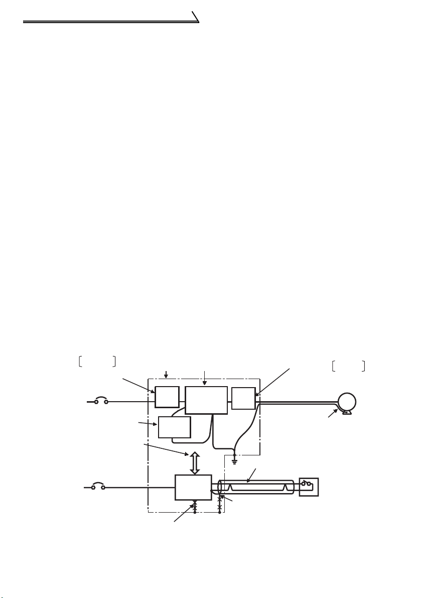
1.2.6 Power-off and magnetic contactor (MC)
(1) Inverter input side magnetic contactor (MC)
On the inverter's input side, it is recommended to provide an MC for the following
purposes. (Refer to page 10 for selection)
1) To release the inverter from the power supply when the inverter protective function
is activated or the drive becomes faulty (e.g. emergency stop operation)
When cycle operation or heavy-duty operation is performed with an optional brake
resistor connected, overheat and burnout of the electrical-discharge resistor can be
prevented if a regenerative brake transistor is damaged due to insufficient heat
capacity of the electrical-discharge resistor and excess regenerative brake duty.
2) To prevent any accident due to an automatic restart at restoration of power after an
inverter stop made by a power failure
3) To rest the inverter for an extended period of time
The control power supply for inverter is always running and consumes a little power.
When stopping the inverter for an extended period of time, powering off the inverter
will save power slightly.
4) To separate the inverter from the power supply to ensure safe maintenance and
inspection work
The inverter's input side MC is used for the above purpose, select class JEM1038AC3 for the inverter input side current when making an emergency stop during
normal operation.
REMARKS
The MC may be switched on/off to start/stop the inverter. However, since repeated inrush
currents at power on will shorten the life of the converter circuit (switching life is about 100,000
times), frequent starts and stops must be avoided. Turn on/off the inverter start controlling
terminals (STF, STR) to run/stop the inverter.
As shown on the right,
always use the start signal
(ON or OFF across
terminals STF or STR-SD)
Power
supply
to make a start or stop.
(Refer to page 29)
*1. When the power supply
is 400V class, install a
step-down transformer.
(2) Handling of output side magnetic contactor
In principle, do not provide a magnetic contactor between the inverter and motor and
switch it from off to on during operation. If it is switched on during inverter operation, a
large inrush current may flow, stopping the inverter due to overcurrent shut-off. When
an MC is provided for switching to the commercial power supply, for example, switch it
on/off after the inverter and motor have stopped.
MCCB
Operation ready
ON
OFF
MC
Start/Stop
MC
Operation
OFF
Inverter Start/Stop Circuit Example
RA
MC
T (*1)
MC
RA
Inverter
W
U
To
V
moto
A
B
C
R/L1
S/L2
T/L3
RA
STF(STR)
SD
16
Main circuit terminals
g
)
1.2.7 Regarding the installation of the reactor
When the inverter is installed near a large-capacity power transformer (500kVA or
more with the wiring length of 10m or less) or the power capacitor is to be switched, an
excessive peak current will flow in the power supply input circuit, damaging the
converter circuit. In such a case, always install the reactor (FR-HEL(-H) /FR-BEL(-H)
or FR-HAL(-H)/FR-BAL(-H)).
•Three-phase power input
FR-HAL(-H)/
FR-BAL(-H)
MCCB
R
Power
supply
S
TZ
•Single phase power input
FR-HAL(-H)/
FR-BAL(-H)
MCCB
R
Power
supply
S
TZ
Inverter
X
R
Y
S
T
P
FR-HEL(-H)/
FR-BEL(-H)(*)
Inverter
X
R
Y
S
P
P1
P1
W
W
1500
U
V
U
V
1000
Power supply equipment
capacity (kVA)
Reactor installation
range
500
010
Wirin
length (m
FR-HEL(-H)/
FR-BEL(-H)(*)
REMARKS
*When connecting the FR-HEL(-H)/FR-BEL(-H), remove the jumper across terminals P-P1.
The wiring length between the FR-HEL(-H)/FR-BEL(-H) and the inverter should be 5m
maximum and as short as possible.
Use the cables which are equal in size to those of the main circuit. (Refer to page 8)
The single-phase 100V power input model does not allow the DC reactor to be fitted.
17
1
WIRING
Main circuit terminals
1.2.8 Regarding noise and the installation of a noise filter
Some noise enters the inverter causing it to malfunction and others are generated by
the inverter causing the malfunction of peripheral devices. Though the inverter is
designed to be insusceptible to noise, it handles low-level signals, so it requires the
following general countermeasures to be taken.
(1) General countermeasures
• Do not run the power cables (I/O cables) and signal cables of the inverter in parallel
with each other and do not bundle them.
• Use twisted shield cables for the detector connecting and control signal cables and
connect the sheathes of the shield cables to terminal SD.
• Earth (Ground) the inverter, motor, etc. at one point.
• Capacitances exist between the inverter's I/O wiring, other cables, earth (ground)
and motor, through which leakage currents flow to cause the earth leakage circuit
breaker, earth (ground) leakage relay and external thermal relay to operate
unnecessarily. To prevent this, take appropriate measures, e.g. set the carrier
frequency in Pr. 72 to a low value, use an earth (ground) leakage circuit breaker
designed for suppression of harmonics and surges, and use the electronic thermal
relay function built in the inverter.
• The input and output of the inverter main circuit include high-degree harmonics,
which may disturb communication devices (AM radios) and sensors used near the
inverter. In this case, install a FR-BIF(-H) optional capacitor type filter (for use on the
input side only) or FR-BSF01 common mode filter to minimize interference.
<Noise reduction examples>
Install filter
on inverter's input side.
Inverter
power supply
Separate inverter and power
line by more than 30cm and
at least 10cm from sensor
circuit.
Control
power supply
FR-BSF01
Install filter FR-BIF
on inverter's input side.
Do not earth (ground)
control box directly.
Do not earth (ground)
control cable.
Control
box
FRBSF01
FR-BIF
Reduce carrier
frequency.
Inverter
Power
supply
for sensor
18
Install filter
on inverter's output side.
FRBSF01
Use 4-core cable for motor
power cable and use one
cable as earth (ground) cable.
Use twisted pair shielded cable.
Do not earth (ground) shield but connect
it to signal common cable.
Sensor
FR-BSF01
IM
Motor
Main circuit terminals
1.2.9 Earthing (Grounding) precautions
z Leakage currents flow in the inverter. To prevent an electric shock, the inverter and
motor must be earthed (grounded). Earthing (Grounding) must conform to the
requirements of national and local safety regulations and electrical codes.
(NEC section 250, IEC 536 class 1 and other applicable standards)
z Use the dedicated earth (ground) terminal to earth (ground) the inverter. (Do not use
the screw in the casing, chassis, etc.)
Use a tinned* crimping terminal to connect the earth (ground) cable. When
tightening the screw, be careful not to damage the threads.
*Plating should not include zinc.
z Use the thickest possible earth (ground) cable. Use the cable whose size is equal to
or greater than that indicated in the following table, and minimize the cable length.
The earthing (grounding) point should be as near as possible to the inverter.
2
Motor Capacity
2.2kW or less 2 (2.5) 2 (2.5)
3.7kW 3.5 (4) 2 (4)
Earth (Ground) Cable Size (Unit: mm
200V class, 100V class 400V class
For use as a product compliant with the Low Voltage Directive, use PVC cable
whose size is indicated within parentheses.
z Earth (Ground) the motor on the inverter side using one wire of the 4-core cable.
)
19
1
WIRING
Main circuit terminals
1.2.10 Power supply harmonics
The inverter may generate power supply harmonics from its converter circuit to affect
the power generator, power capacitor etc. Power supply harmonics are different from
noise and leakage currents in source, frequency band and transmission path. Take the
following countermeasure suppression techniques.
The following table indicates differences between harmonics and noise:
Item Harmonics Noise
Frequency
Environment To-electric channel, power impedance To-space, distance, wiring path
Quantitative
understanding
Generated amount Nearly proportional to load capacity
Affected equipment
immunity
Suppression example Provide reactor. Increase distance.
Suppression technique
Harmonic currents produced
on the power supply side by
the inverter change with such
conditions as whether there
are wiring impedances and a
DC reactor (FR-HEL(-H)/FRBEL(-H) or FR-HAL(-H)/FRBAL(-H)) and the magnitudes
of output frequency and
output current on the load
side.
For the output frequency and output current, we understand that they should be
calculated in the conditions under the rated load at the maximum operating frequency.
CAUTION
The power factor improving capacitor and surge suppressor on the inverter
output side may be overheated or damaged by the high frequency components
of the inverter output. Also, since an excessive current flows in the inverter to
activate overcurrent protection, do not provide a capacitor and surge
suppressor on the inverter output side when the motor is driven by the inverter.
To improve the power factor, insert a reactor on the inverter's primary side or
DC circuit. For full information, refer to page 17.
Normally 40th to 50th degrees or less
(up to 3kHz or less)
Theoretical calculation possible
Specified in standard per equipment
FR-HEL(-H)
/FR-BEL(-H)
MCCB
FR-HAL(-H)
/FR-BAL(-H)
High frequency (several 10kHz
to 1GHz order)
Random occurrence,
quantitative grasping difficult
Change with current variation
ratio (larger as switching speed
increases)
Different depending on maker's
equipment specifications
Motor
IM
Inverter
Do not provide power factor
improving capacitor.
20
 Loading...